US6351381B1 - Heat management system - Google Patents
Heat management systemDownload PDFInfo
- Publication number
- US6351381B1 US6351381B1US09/885,470US88547001AUS6351381B1US 6351381 B1US6351381 B1US 6351381B1US 88547001 AUS88547001 AUS 88547001AUS 6351381 B1US6351381 B1US 6351381B1
- Authority
- US
- United States
- Prior art keywords
- management system
- heat
- electronic systems
- heat management
- heat exchanger
- Prior art date
- Legal status (The legal status is an assumption and is not a legal conclusion. Google has not performed a legal analysis and makes no representation as to the accuracy of the status listed.)
- Expired - Fee Related
Links
Images


Classifications
- F—MECHANICAL ENGINEERING; LIGHTING; HEATING; WEAPONS; BLASTING
- F25—REFRIGERATION OR COOLING; COMBINED HEATING AND REFRIGERATION SYSTEMS; HEAT PUMP SYSTEMS; MANUFACTURE OR STORAGE OF ICE; LIQUEFACTION SOLIDIFICATION OF GASES
- F25D—REFRIGERATORS; COLD ROOMS; ICE-BOXES; COOLING OR FREEZING APPARATUS NOT OTHERWISE PROVIDED FOR
- F25D1/00—Devices using naturally cold air or cold water
- H—ELECTRICITY
- H05—ELECTRIC TECHNIQUES NOT OTHERWISE PROVIDED FOR
- H05K—PRINTED CIRCUITS; CASINGS OR CONSTRUCTIONAL DETAILS OF ELECTRIC APPARATUS; MANUFACTURE OF ASSEMBLAGES OF ELECTRICAL COMPONENTS
- H05K7/00—Constructional details common to different types of electric apparatus
- H05K7/20—Modifications to facilitate cooling, ventilating, or heating
- H05K7/20536—Modifications to facilitate cooling, ventilating, or heating for racks or cabinets of standardised dimensions, e.g. electronic racks for aircraft or telecommunication equipment
- H05K7/20609—Air circulating in closed loop within cabinets wherein heat is removed through air-to-liquid heat-exchanger
- F—MECHANICAL ENGINEERING; LIGHTING; HEATING; WEAPONS; BLASTING
- F28—HEAT EXCHANGE IN GENERAL
- F28D—HEAT-EXCHANGE APPARATUS, NOT PROVIDED FOR IN ANOTHER SUBCLASS, IN WHICH THE HEAT-EXCHANGE MEDIA DO NOT COME INTO DIRECT CONTACT
- F28D15/00—Heat-exchange apparatus with the intermediate heat-transfer medium in closed tubes passing into or through the conduit walls ; Heat-exchange apparatus employing intermediate heat-transfer medium or bodies
- F28D15/02—Heat-exchange apparatus with the intermediate heat-transfer medium in closed tubes passing into or through the conduit walls ; Heat-exchange apparatus employing intermediate heat-transfer medium or bodies in which the medium condenses and evaporates, e.g. heat pipes
- F28D15/0266—Heat-exchange apparatus with the intermediate heat-transfer medium in closed tubes passing into or through the conduit walls ; Heat-exchange apparatus employing intermediate heat-transfer medium or bodies in which the medium condenses and evaporates, e.g. heat pipes with separate evaporating and condensing chambers connected by at least one conduit; Loop-type heat pipes; with multiple or common evaporating or condensing chambers
- F—MECHANICAL ENGINEERING; LIGHTING; HEATING; WEAPONS; BLASTING
- F28—HEAT EXCHANGE IN GENERAL
- F28F—DETAILS OF HEAT-EXCHANGE AND HEAT-TRANSFER APPARATUS, OF GENERAL APPLICATION
- F28F1/00—Tubular elements; Assemblies of tubular elements
- F28F1/10—Tubular elements and assemblies thereof with means for increasing heat-transfer area, e.g. with fins, with projections, with recesses
- F28F1/12—Tubular elements and assemblies thereof with means for increasing heat-transfer area, e.g. with fins, with projections, with recesses the means being only outside the tubular element
- F28F1/14—Tubular elements and assemblies thereof with means for increasing heat-transfer area, e.g. with fins, with projections, with recesses the means being only outside the tubular element and extending longitudinally
- F28F1/22—Tubular elements and assemblies thereof with means for increasing heat-transfer area, e.g. with fins, with projections, with recesses the means being only outside the tubular element and extending longitudinally the means having portions engaging further tubular elements
- F—MECHANICAL ENGINEERING; LIGHTING; HEATING; WEAPONS; BLASTING
- F28—HEAT EXCHANGE IN GENERAL
- F28F—DETAILS OF HEAT-EXCHANGE AND HEAT-TRANSFER APPARATUS, OF GENERAL APPLICATION
- F28F1/00—Tubular elements; Assemblies of tubular elements
- F28F1/10—Tubular elements and assemblies thereof with means for increasing heat-transfer area, e.g. with fins, with projections, with recesses
- F28F1/12—Tubular elements and assemblies thereof with means for increasing heat-transfer area, e.g. with fins, with projections, with recesses the means being only outside the tubular element
- F28F1/24—Tubular elements and assemblies thereof with means for increasing heat-transfer area, e.g. with fins, with projections, with recesses the means being only outside the tubular element and extending transversely
- F28F1/32—Tubular elements and assemblies thereof with means for increasing heat-transfer area, e.g. with fins, with projections, with recesses the means being only outside the tubular element and extending transversely the means having portions engaging further tubular elements
- F—MECHANICAL ENGINEERING; LIGHTING; HEATING; WEAPONS; BLASTING
- F28—HEAT EXCHANGE IN GENERAL
- F28F—DETAILS OF HEAT-EXCHANGE AND HEAT-TRANSFER APPARATUS, OF GENERAL APPLICATION
- F28F2275/00—Fastening; Joining
- F28F2275/12—Fastening; Joining by methods involving deformation of the elements
Definitions
- the present inventionrelates to an apparatus and system for improving heat management in an electronic system, and more particularly to a hybrid heat exchange system in which three heat exchange assemblies work in concert to manage the thermal profile of the electronic system.
- the performance of electronic systemsis limited by temperature.
- Semiconductor device performancedegrades when the internal temperature reaches or exceeds a particular limit. For example, in silicon integrated circuit devices, for each ten degree centigrade rise in junction temperature, the operating lifetime of the semiconductor device is decreased by a factor of at least two. Demands by OEMs for smaller package sizes and increased device densities has resulted in higher power densities, with the concomitant need for efficient heat dissipation becoming extremely important.
- next generation, highly integrated semiconductor deviceshaving relatively high thermal energy generation.
- Such devicesare frequently found in present day and next generation communications equipment e.g., LPA amplifiers, radio based telephony, and other associated electronic systems.
- the manner of cooling these devices and systemshas depended upon many parameters, including the space available for the cooling process, the temperatures to be encountered, the location(s) of high thermal output electronic components, and the ability to distribute or “spread” the thermal energy over sufficient surface area to provide for efficient heat transfer.
- a first heat exchange assemblyincludes at least one cold plate that is thermally interconnected with at least one of the electronic systems and components.
- a channelis defined in the cold plate that supports a tube having an entrance opening, an exit opening, and is arranged to be in confronting relation to a portion of the electronic systems and components so as to form a passageway for a liquid coolant fluid to travel through the channel in thermal communication with the portion of the electronic systems and components.
- a second heat exchange assemblyincludes a condenser arranged in fluid flow communication with the entrance opening and the exit opening of the tube and a plurality of fans arranged in confronting relation to the condenser.
- a third heat exchange assemblyis provided that includes at least one stack of substantially parallel plates arranged in two-plate assemblies. Each two-plate assembly has a closed end and an open end such that a closed end of one two-plate assembly is sandwiched between an open end of two adjacent two-plate assemblies.
- At least two fansare provided, with one fan arranged so as to: (i) blow air onto a portion of the plurality of electronic systems and components, (ii) draw heated air away from a portion of the plurality of electronic systems and components, and (iii) blow the heated air into the open ends of the two-plate assemblies.
- Another fansupplies cooler, ambient air to the adjacent two plate assembly to remove the heat and vent it outside of the cabinet through a side wall.
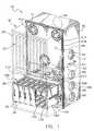
- FIG. 1is a perspective view, partially in phantom, of an electronics cabinet cooled by a heat management system formed in accordance with the present invention
- FIG. 2is a perspective view of a heat management system formed in accordance with the present invention.
- FIG. 3is a perspective view of a portion of a primary heat exchange assembly showing a cold plate exploded away from a housing containing electronic systems to be cooled;
- FIG. 4is a perspective view of a cold plate
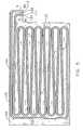
- FIG. 5is a plan view of the cold plate shown in FIG. 4;
- FIG. 6is a cross-sectional view of a portion of the cold plate shown in FIGS. 4 and 5, as taken along line 6 — 6 in FIG. 5;
- FIG. 6 ais a cross-sectional view of a portion of the cold plate shown in FIGS. 4 and 5, as taken along line 6 a — 6 a in FIG. 5, showing a tube positioned within a channel in the cold plate prior to press-fitting;
- FIG. 6 bis a cross-sectional view of a portion of the cold plate shown in FIGS. 4 and 5, as taken along line 6 b — 6 b in FIG. 5, showing the tube positioned within the channel in the cold plate after press-fitting;
- FIG. 7is an exploded and partially broken-away perspective view of a secondary heat exchange assembly formed in accordance with the present invention.
- FIG. 8is a plan view of a condenser used in connection with the secondary heat exchange assembly
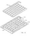
- FIG. 9is a plan view of a tertiary heat exchange assembly formed in accordance with the present invention.
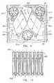
- FIG. 10is a sectional view of an air-to-air heat exchanger, as taken along lines 10 — 10 in FIG. 9 .
- a thermal management system 10 formed in accordance with the present inventioncomprises a primary heat exchange assembly 100 , a secondary heat exchange assembly 200 , and a tertiary heat exchange assembly 300 .
- Secondary and tertiary heat exchange assemblies 200 and 300are housed in a first cabinet 15 which is attached to a portion of a second electronic systems cabinet 18 , e.g., a CDMA systems cabinet (FIG. 1 ).
- Electronic systems cabinet 18houses various heat generating electronic systems and devices, e.g., one or more LPA amplifiers and associated electronics modules 20 and one or more communications control systems and radio units 22 .
- Cabinets 15 and 18comprise generally rectilinear structures that are arranged so as to thermally communicate with one another, via thermal management system 10 . More particularly, cabinet 15 comprises an upper compartment 35 and a lower compartment 37 that house secondary and tertiary heat exchange assemblies 200 and 300 , respectively.
- a hinged panel 39operates to close-off both upper compartment 35 and lower compartment 37 (FIG. 1 ).
- Hinged panel 39includes three openings 41 a , 41 b , and 41 c in a top portion which allow for the only fluid communication between the interior of upper compartment 35 of cabinet 15 and top portion 30 of electronic systems cabinet 18 .
- the walls of cabinet 15 that bound upper compartment 35include side wall openings 44 and a rear wall opening 46 .
- Lower compartment 37is sized and shaped to house secondary heat exchange assembly 200 .
- a plurality of openings 50are defined through the side walls of cabinet 15 so as to provide for flow communication of air into lower compartment 37 and rear wall opening 52 provides for flow communication of air out of lower compartment 37 .
- the compartments of cabinet 15are typically sealed by welding or application of a sealant to maintain separation between them and the ambient environment. In this way, cabinet 15 is sufficiently sealed against dust, water, etc., so as to meet NEMA 4 and NEMA 12 standards. All sealants, gaskets, etc., are selected so as to be compatible with Underwriter Laboratories standard 94 , rating V- 1 or V- 0 .
- primary heat exchange assembly 100is positioned within bottom portion 28 of electronic systems cabinet 18 , and includes a plurality of cold plates 103 , a plurality of tubes 104 , a plurality of coolant transport conduits 106 .
- each cold plate 103is formed from a flat planar sheet of thermally conductive material, such as copper, aluminum, steel or the like.
- a wall 118 of housing 119(that supports electronic components and circuits, e.g., an LPA amplifier) is fastened to a bottom surface 115 of each cold plate 103 , and a flat cover sheet 116 is fastened to surface 117 , via plurality of fasteners 120 , so as to be in close thermal communication with cold plate 103 and tube 104 .
- Fasteners 120extend transversely through cold plate 103 .
- Each cold plate 103includes a channel having a heat absorbing section 122 and a heat transporting section 123 extending through surface 117 and into the interior of the plate.
- Heat absorbing section 122 and heat transporting section 123often have a rectilinear cross-section, but other cross-sectional shapes, i.e., oval, round, polygonal, may also be used with good effect.
- Heat absorbing section 122cuts a serpentine path through surface 117 of cold plate 103
- a heat transporting section 123cuts a path through surface 117 that is peripheral to, and partially circumscribes, heat absorbing section 122 (FIGS. 4 and 5 ).
- Heat absorbing section 122has a width or diameter, and depth that is smaller than the width or diameter and depth of heat transporting section 123 .
- Heat absorbing section 122 and heat transporting section 123are continuous throughout the interior of cold plate 103 , with heat absorbing section 122 defining an entrance port 124 , and heat transporting section 123 defining an exit port 126 at one end of cold plate 103 .
- Each tube 104has a first open end 111 and a second open end 112 , and is preferably formed from a cylinder of malleable and thermally conductive metal, such as copper, aluminum, or the like so as to be compatible with a press-fitting operation during assembly of tube 104 to cold plate 103 .
- Tube 104has an outer diameter that approximately corresponds to the width of, and is larger than the depth of, heat absorbing section 122 . When positioned within heat absorbing section 122 , a portion of tube 104 preferably stands proud of surface 117 . During press-fitting, the top portion of tube 104 , that stands proud of surface 117 , is plastically deformed so as to be substantially flush with surface 117 (FIGS. 6 a and 6 b ).
- tube 104may be securely press-fit into heat absorbing section 122 , and maintained in close thermal communication with cold plate 103 by the inclusion of a thermally conductive epoxy or the like in the bottom of the channel.
- coolant fluid 127e.g., an effective mixture of propylene glycol and water or the like, FIG. 7 ).
- heat transporting section 123has a larger width or diameter than heat absorbing section 122 , it also has a larger width or diameter than tube 104 . Thus only substantially line contact is made between the outer surface of tube 104 and the walls of heat transporting section 123 .
- Tube 104is not press-fit into heat transporting section 123 , but a small amount of non-thermally conductive epoxy may be used to maintain tube 104 within heat transporting section 123 .
- This constructionallows for minimum heat transfer between the portion of coolant fluid 127 that has been heated during its pass through the serpentine portion of heat absorbing section 122 , and cold plate 103 , or the cooler portions of coolant 127 that are entering heat absorbing section 122 .
- coolant fluid 127may be pumped into open end 111 of tube 104 located at entrance port 124 where it circulates throughout the interior of cold plate 103 , tube 104 , and emerges from open end 112 located at exit port 126 .
- the serpentine shape of heat absorbing section 122 and tube 104causes coolant fluid 127 flowing through it to be dispersed across a substantial portion of cold plate 103 , and therethrough to wall 118 of electronics module housing 119 so as to achieve efficient and thorough heat transfer from the enclosed LPA amplifiers or other electronics devices to cold plate 103 and coolant fluid 127 .
- a pair of coolant transport conduits 106are positioned on the outer surface of each cold plate 103 , on the side opposite to the channel, and are shielded by a cover 107 .
- One conduit 106is connected to open end 111 of tube 104 at entrance port 124 and one conduit 106 is connected to open end 112 of tube 104 at exit port 126 .
- Coolant fluid ports 128 , 130are each disposed at an open end of a coolant transport conduit 106 , and are sized and shaped to sealingly interconnect with a distribution manifold 113 , via connectors 129 , 132 , and therethrough to hoses 134 , 135 that together guide the circulation of coolant fluid 127 between tubes 104 in each of cold plates 103 and coolant reservoir 109 .
- the heat removed by primary heat exchange assembly 100is approximately 4,500 watts, with cold plates 103 maintaining 80° C. at the outer surface of each electronics module housing, and with the entire system operating at +50° C. ambient temperature.
- a coolant reservoir 109is normally positioned within lower compartment 37 of cabinet 15 .
- Coolant reservoir 109comprises a tank including an inlet port 133 , an outlet port 137 and a vented lid 139 .
- a float gauge 141may be positioned within coolant reservoir 109 to allow for monitoring of the coolant fluid level (not shown).
- coolant reservoir 109comprises a triangular cross-sectional shape, and holds about twelve liters of coolant 127 .
- Coolant reservoir 109may also include a thermocouple for monitoring coolant temperature.
- Secondary heat exchange assembly 200includes a liquid-to-air heat exchanger 212 , a pumping system 215 , and a plurality of fans 217 .
- Liquid-to-air heat exchanger 212is positioned adjacent to an interior facing wall of coolant reservoir 109 .
- Liquid-to-air heat exchanger 212includes a generally rectangular frame 218 , an input port 221 and an output port 223 that are typically located on a bottom edge of frame 218 .
- Plurality of fans 217are mounted to a supporting bracket 216 located on a side surface of frame 218 of liquid-to-air heat exchanger 212 so as to be positioned adjacent to the interior wall of coolant reservoir 109 .
- Liquid-to-air heat exchanger 212includes a condenser 230 comprising a frame-mount 234 that supports a serpentine tube 236 that traverses the interior portions of a fin stack 238 (FIGS. 7 and 8 ).
- Frame-mount 234is fastened to a side surface of frame 218 in spaced confronting relation to plurality of fans 217 .
- coolant liquid 127 from plurality of cold plates 103may be circulated through condenser 230 so as to be cooled by plurality of fans 217 .
- Outside ambient airis drawn into lower compartment 37 via side wall openings 50 , and the exhaust from fans 217 is directed out of cabinet 15 via rear wall opening 52 .
- heated coolant fluid 127 from plurality of cold plates 103is cooled prior to being deposited in coolant reservoir 109 , via inlet port 133 , and the exhaust heat is transferred from cabinet 15 in an air stream moving outwardly through rear wall opening 52 .
- pumping system 215includes two pumps 240 , check valves 243 , and pressure switch 246 . Any of the well known pumps, valves and pressure switches may be used in constructing pump system 215 with adequate results.
- Pumping system 215is arranged and interconnected between coolant reservoir 109 and plurality of cold plates 103 so as to draw cooled coolant fluid 127 from coolant reservoir 109 and return it to each of cold plates 103 in a circulatory fashion. In this arrangement, only one of the two pumps 240 is running at any given time during the operation of primary and secondary heat exchange assemblies 100 and 200 .
- Pressure switch 246is adapted as a monitor for the system pressure to determine whether at least one pump is operating. If at least one pump is not running, the second pump may be switched on so as to prevent a failure of the system.
- a programmable controller 250(FIG. 2) or other known control system is employed to control and operate pumping system 215 and plurality of fans 217 . More particularly, programmable controller 250 is electrically interconnected to pumping system 215 and plurality of fans 217 , and may be selected from any of the well known prior art programmable controllers capable of continuous use at ambient temperatures of approximately ⁇ 40° C. to +65° C. It will be understood that other types of programmable devices may be used in connection with the present invention as equivalents to the foregoing programmable controller, such as, a general purpose computer, a personal computer, a specially designed computer or equivalent electronic circuit capable of functioning in substantially the same way, with substantially the same result, as the foregoing programmable controller, or the like programmable means. It will also be understood that an appropriate power supply interconnected to a source of electrical energy is required to operate the programmable controller or equivalent means, switches, sensors, valves, pumps and each will be an obvious design choice for those skilled in the art.
- tertiary heat exchange assembly 300is located within upper compartment 35 of cabinet 15 in air-flow isolation from lower compartment 37 and secondary heat exchange assembly 200 .
- Tertiary heat exchange assembly 300includes air-to-air heat exchanger 305 , blower fan 310 , and intake fans 317 .
- air-to-air heat exchanger 305comprises two stacks 320 , each having a plurality of substantially parallel, spaced-apart plates 322 that are supported within upper compartment 35 of cabinet 15 .
- Each plate 322has a generally flat, rectilinear shape, with a diamond shape being preferred in one application.
- Each of plates 322may be formed from a single sheet of metal or other good thermal conductor, and includes means defined along at least two parallel opposing edges for joining adjacent plates to one another so as to form two-plate assemblies 326 .
- An air-to-air heat exchanger 305that has been found to provide adequate results in connection with the present invention is the one manufactured by the HEATEX AB company of Tommarpsväägen 46, SE-231 65 Trelleborg, Sweden, and designated Model RH (Rhombical).
- a first two-plate assemblyallows air to flow between its plates, but not to enter further into the interior of cabinet 15 .
- a second adjacent two-plate assemblyallows air to flow between its plates, but not to exit the interior of cabinet 15 .
- outside ambient airis circulated through air-to-air heat exchanger 305 by fans 17 located in side wall openings 44
- air from the interior of cabinet 15is circulated through air-to-air heat exchanger 305 via fans 317 located in openings 41 a and 41 b of wall 39 , and reintroduced into electronics cabinet 18 via blower 310 located in opening 41 c .
- This arrangementprevents the exchange of outside ambient air with air disposed within the lower compartment 37 of cabinet 15 .
- Tertiary heat exchange assembly 300operates in such a way that a maximum 15° C. temperature rise inside the enclosure is experienced during a +50° C. ambient temperature.
Landscapes
- Engineering & Computer Science (AREA)
- Physics & Mathematics (AREA)
- Thermal Sciences (AREA)
- Mechanical Engineering (AREA)
- General Engineering & Computer Science (AREA)
- Geometry (AREA)
- Life Sciences & Earth Sciences (AREA)
- Sustainable Development (AREA)
- Aviation & Aerospace Engineering (AREA)
- Microelectronics & Electronic Packaging (AREA)
- Chemical & Material Sciences (AREA)
- Combustion & Propulsion (AREA)
- Cooling Or The Like Of Electrical Apparatus (AREA)
Abstract
Description
Claims (27)
Priority Applications (4)
| Application Number | Priority Date | Filing Date | Title |
|---|---|---|---|
| US09/885,470US6351381B1 (en) | 2001-06-20 | 2001-06-20 | Heat management system |
| KR1020010062187AKR20020096816A (en) | 2001-06-20 | 2001-10-09 | Heat management system |
| PCT/US2002/003643WO2003001861A1 (en) | 2001-06-20 | 2002-02-08 | Heat management system |
| CN02105553ACN1392768A (en) | 2001-06-20 | 2002-04-17 | Heat control system |
Applications Claiming Priority (1)
| Application Number | Priority Date | Filing Date | Title |
|---|---|---|---|
| US09/885,470US6351381B1 (en) | 2001-06-20 | 2001-06-20 | Heat management system |
Publications (1)
| Publication Number | Publication Date |
|---|---|
| US6351381B1true US6351381B1 (en) | 2002-02-26 |
Family
ID=25386970
Family Applications (1)
| Application Number | Title | Priority Date | Filing Date |
|---|---|---|---|
| US09/885,470Expired - Fee RelatedUS6351381B1 (en) | 2001-06-20 | 2001-06-20 | Heat management system |
Country Status (4)
| Country | Link |
|---|---|
| US (1) | US6351381B1 (en) |
| KR (1) | KR20020096816A (en) |
| CN (1) | CN1392768A (en) |
| WO (1) | WO2003001861A1 (en) |
Cited By (105)
| Publication number | Priority date | Publication date | Assignee | Title |
|---|---|---|---|---|
| US20030051860A1 (en)* | 2001-09-20 | 2003-03-20 | Intel Corporation | Computer system having a chassis-level capillary pump loop transferring heat to a frame-level thermal interface component |
| US20030128516A1 (en)* | 2002-01-04 | 2003-07-10 | Faneuf Barrett M. | Frame-level thermal interface component for transfer of heat from an electronic component of a computer system |
| US20030128525A1 (en)* | 2002-01-04 | 2003-07-10 | Berry William E. | Computer system which locks a server unit subassembly in a selected position in a support frame |
| US20030128508A1 (en)* | 2002-01-04 | 2003-07-10 | Faneuf Barrett M. | Computer system having a plurality of server units transferring heat to a fluid flowing through a frame-level fluid-channeling structure |
| US6643132B2 (en) | 2002-01-04 | 2003-11-04 | Intel Corporation | Chassis-level thermal interface component for transfer of heat from an electronic component of a computer system |
| US20030230399A1 (en)* | 2002-06-14 | 2003-12-18 | Hurlbert Kathryn M. | Apparatus and method for extracting heat from a device |
| US20040017655A1 (en)* | 2002-07-23 | 2004-01-29 | Silicon Graphics, Inc. | Method and rack for exchanging air with modular bricks in a computer system |
| US20040017654A1 (en)* | 2002-07-23 | 2004-01-29 | Silicon Graphics, Inc. | External fan and method for exchanging air with modular bricks in a computer system |
| US20040027803A1 (en)* | 2002-08-07 | 2004-02-12 | Tsai Chung Yen | High efficiency heat dissipated power supply |
| US6693797B2 (en) | 2002-01-04 | 2004-02-17 | Intel Corporation | Computer system having a chassis-level thermal interface component and a frame-level thermal interface component that are thermally engageable with and disengageable from one another |
| US20040100767A1 (en)* | 2002-11-25 | 2004-05-27 | Lockheed Martin Corporation | Rugged modular pc 104 chassis with blind mate connector and forced convection cooling capabilities |
| US6749012B2 (en)* | 2002-04-30 | 2004-06-15 | Intel Corporation | Liquid cooling system for processors |
| US20040125561A1 (en)* | 2002-12-27 | 2004-07-01 | Gwin Paul J | Sealed and pressurized liquid cooling system for microprocessor |
| US6775137B2 (en) | 2002-11-25 | 2004-08-10 | International Business Machines Corporation | Method and apparatus for combined air and liquid cooling of stacked electronics components |
| US20040252453A1 (en)* | 2003-06-11 | 2004-12-16 | Hewlett-Packard Development Company, L.P. | Computer cooling system and method |
| US20050133214A1 (en)* | 2003-12-19 | 2005-06-23 | Teradyne, Inc. | Modular rackmount chiller |
| US20050133200A1 (en)* | 2003-12-17 | 2005-06-23 | Malone Christopher G. | One or more heat exchanger components in major part operably locatable outside computer chassis |
| US20050133231A1 (en)* | 2003-12-19 | 2005-06-23 | James Conerton | Apparatus and method for storing electronics |
| US20050141196A1 (en)* | 2003-12-17 | 2005-06-30 | Takaaki Yamatani | Liquid cooling system and electronic equipment using the same |
| US20050180105A1 (en)* | 2004-02-16 | 2005-08-18 | Hitoshi Matsushima | Redundant liquid cooling system and electronic apparatus having the same therein |
| US20050225936A1 (en)* | 2002-03-28 | 2005-10-13 | Tony Day | Cooling of a data centre |
| US20050223730A1 (en)* | 2004-04-12 | 2005-10-13 | York International Corporation | Electronic component cooling system for an air-cooled chiller |
| US20050231910A1 (en)* | 2004-04-19 | 2005-10-20 | Hewlett-Packard Development Company, L.P. | Liquid loop with multiple heat exchangers for efficient space utilization |
| US20050231913A1 (en)* | 2004-04-19 | 2005-10-20 | Hewlett-Packard Development Company, L.P. | External liquid loop heat exchanger for an electronic system |
| US20050241812A1 (en)* | 2004-04-29 | 2005-11-03 | Hewlett-Packard Development Company, L.P. | Multiple-pass heat exchanger with gaps between fins of adjacent tube segments |
| US20060007657A1 (en)* | 2004-07-07 | 2006-01-12 | Teradyne, Inc. | Thermally enhanced pressure regulation of electronics cooling systems |
| US6987673B1 (en)* | 2003-09-09 | 2006-01-17 | Emc Corporation | Techniques for cooling a set of circuit boards within a rack mount cabinet |
| US20060059936A1 (en)* | 2004-09-17 | 2006-03-23 | Radke Robert E | Systems and methods for providing cooling in compressed air storage power supply systems |
| US20060067047A1 (en)* | 2004-09-30 | 2006-03-30 | Pfahnl Andreas C | Modular liquid cooling of electronic assemblies |
| DE202005005452U1 (en)* | 2005-04-06 | 2006-08-17 | Getriebebau Nord Gmbh & Co. Kg | Gear cooler e.g. for cooling gear, has housing wall having exterior surface and inner surface with cooling agent line provided, being in connection with only exterior surface of housing wall |
| US7219714B1 (en)* | 2005-08-04 | 2007-05-22 | Sun Microsystems, Inc. | Multiple component field-replaceable active integrated liquid pump heat sink module for thermal management of electronic components |
| US20070158053A1 (en)* | 2003-06-07 | 2007-07-12 | Michael Nicolai | Cooling plant for one or more switch cabinets |
| US7262964B1 (en) | 2005-04-27 | 2007-08-28 | Hewlett-Packard Development Company, L.P. | Airflow control baffle |
| US20070211429A1 (en)* | 2006-03-09 | 2007-09-13 | Kabushiki Kaisha Toshiba | Housing apparatus for heat generating device |
| US20070211428A1 (en)* | 2006-03-08 | 2007-09-13 | Cray Inc. | Multi-stage air movers for cooling computer systems and for other uses |
| US20080082219A1 (en)* | 2006-09-29 | 2008-04-03 | Belady Christian L | Heat sink system management |
| US20080174962A1 (en)* | 2007-01-24 | 2008-07-24 | Christian Belady | System and method for cooling an electronic component |
| US20090052132A1 (en)* | 2007-06-12 | 2009-02-26 | Fernandez Pedro A | Heat Exchanger for Outdoor Enclosures |
| US20090117843A1 (en)* | 2007-11-02 | 2009-05-07 | Ice Qube, Inc. | Cooling apparatus and method |
| US20090154091A1 (en)* | 2007-12-17 | 2009-06-18 | Yatskov Alexander I | Cooling systems and heat exchangers for cooling computer components |
| US20090190301A1 (en)* | 2008-01-24 | 2009-07-30 | Alpha Networks Inc. | Server device |
| US20090201644A1 (en)* | 2008-02-11 | 2009-08-13 | Kelley Douglas P | Systems and associated methods for cooling computer components |
| US20090244826A1 (en)* | 2008-04-01 | 2009-10-01 | Doll Wade J | Airflow management apparatus for computer cabinets and associated methods |
| US20100097752A1 (en)* | 2008-10-17 | 2010-04-22 | Doll Wade J | Airflow intake systems and associated methods for use with computer cabinets |
| US20100097751A1 (en)* | 2008-10-17 | 2010-04-22 | Doll Wade J | Air conditioning systems for computer systems and associated methods |
| US20100149754A1 (en)* | 2007-03-14 | 2010-06-17 | Zonit Structured Solutions, Llc | Air-based cooling for data center rack |
| US20100313590A1 (en)* | 2009-06-10 | 2010-12-16 | International Business Machines Corporation | Liquid-cooled cooling apparatus, electronics rack and methods of fabrication thereof |
| US20110073279A1 (en)* | 2009-09-29 | 2011-03-31 | Hong Fu Jin Precision Industry (Shenzhen) Co., Ltd | Electrical control cabinet |
| US20110088600A1 (en)* | 2009-10-16 | 2011-04-21 | Macrae Allan J | Eddy-free high velocity cooler |
| US8472181B2 (en) | 2010-04-20 | 2013-06-25 | Cray Inc. | Computer cabinets having progressive air velocity cooling systems and associated methods of manufacture and use |
| US20130189916A1 (en)* | 2012-01-20 | 2013-07-25 | Delta Electronics, Inc. | Rack system and ventilation apparatus thereof |
| US8540557B1 (en)* | 2004-08-02 | 2013-09-24 | Bard Manufacturing Company | Wall curb for air treatment system |
| US20130294027A1 (en)* | 2012-05-07 | 2013-11-07 | Abb Oy | Electronics compartment |
| US20140049146A1 (en)* | 2011-09-23 | 2014-02-20 | Cloud Dynamics Inc. | Data center equipment cabinet system |
| US8730674B2 (en) | 2011-12-12 | 2014-05-20 | Toyota Motor Engineering & Manufacturing North America, Inc. | Magnetic fluid cooling devices and power electronics assemblies |
| US20140345834A1 (en)* | 2010-08-20 | 2014-11-27 | Manufacturing Resources International, Inc. | System for thermally controlling an electronic display with reduced noise emissions |
| US20140352929A1 (en)* | 2013-05-31 | 2014-12-04 | The Boeing Company | Dual-Function Food Tray Support Tubes for a Galley Cart |
| US9429341B2 (en)* | 2012-01-20 | 2016-08-30 | Berg Companies, Inc. | Expandable shelter HVAC systems |
| CN106102365A (en)* | 2016-05-27 | 2016-11-09 | 东莞市联洲知识产权运营管理有限公司 | A high cooling box |
| US9693485B2 (en) | 2012-12-03 | 2017-06-27 | Nec Corporation | Cooling system for electronic device storing apparatus and cooling system for electronic device storing building |
| US9797588B2 (en) | 2008-03-03 | 2017-10-24 | Manufacturing Resources International, Inc. | Expanded heat sink for electronic displays |
| US9801305B2 (en) | 2008-03-03 | 2017-10-24 | Manufacturing Resources International, Inc. | Heat exchanger for an electronic display |
| US9835893B2 (en) | 2008-03-03 | 2017-12-05 | Manufacturing Resources International, Inc. | Heat exchanger for back to back electronics displays |
| US9894800B2 (en) | 2008-03-03 | 2018-02-13 | Manufacturing Resources International, Inc. | Constricted convection cooling system for an electronic display |
| US10080316B2 (en) | 2009-11-13 | 2018-09-18 | Manufacturing Resources International, Inc. | Electronic display assembly having thermal cooling plate and optional convective air cooling loop |
| US10088702B2 (en) | 2013-07-08 | 2018-10-02 | Manufacturing Resources International, Inc. | Figure eight closed loop cooling system for electronic display |
| US10194564B2 (en) | 2014-04-30 | 2019-01-29 | Manufacturing Resources International, Inc. | Back to back electronic display assembly |
| US10212845B2 (en) | 2014-03-11 | 2019-02-19 | Manufacturing Resources International, Inc. | Hybrid rear cover and mounting bracket for electronic display |
| US10278311B2 (en) | 2015-02-17 | 2019-04-30 | Manufacturing Resources International, Inc. | Perimeter ventilation system |
| CN109845052A (en)* | 2016-08-31 | 2019-06-04 | 恩耐公司 | Laser cooling system |
| US10314212B2 (en) | 2008-12-18 | 2019-06-04 | Manufacturing Resources International, Inc. | System for cooling an electronic image assembly with circulating gas and ambient gas |
| US10398066B2 (en) | 2017-04-27 | 2019-08-27 | Manufacturing Resources International, Inc. | System and method for preventing display bowing |
| US10420257B2 (en) | 2008-03-26 | 2019-09-17 | Manufacturing Resources International, Inc. | System and method for maintaining a consistent temperature gradient across an electronic display |
| US10485113B2 (en) | 2017-04-27 | 2019-11-19 | Manufacturing Resources International, Inc. | Field serviceable and replaceable display |
| US10524384B2 (en) | 2013-03-15 | 2019-12-31 | Manufacturing Resources International, Inc. | Cooling assembly for an electronic display |
| US10524397B2 (en) | 2013-03-15 | 2019-12-31 | Manufacturing Resources International, Inc. | Heat exchanger assembly for an electronic display |
| US10559965B2 (en) | 2017-09-21 | 2020-02-11 | Manufacturing Resources International, Inc. | Display assembly having multiple charging ports |
| US10660245B2 (en) | 2012-10-16 | 2020-05-19 | Manufacturing Resources International, Inc. | Back pan cooling assembly for electronic display |
| US20200191042A1 (en)* | 2018-12-13 | 2020-06-18 | General Electric Company | Liquid driven thermal module and thermal management system |
| WO2020125543A1 (en)* | 2018-12-18 | 2020-06-25 | 山东中车风电有限公司 | Temperature control system of high-power converter of wind turbine generator set |
| US10784645B2 (en) | 2018-03-12 | 2020-09-22 | Nlight, Inc. | Fiber laser having variably wound optical fiber |
| US10795413B1 (en) | 2019-04-03 | 2020-10-06 | Manufacturing Resources International, Inc. | Electronic display assembly with a channel for ambient air in an access panel |
| US10820445B2 (en) | 2016-03-04 | 2020-10-27 | Manufacturing Resources International, Inc. | Cooling system for double sided display assembly |
| US10827656B2 (en) | 2008-12-18 | 2020-11-03 | Manufacturing Resources International, Inc. | System for cooling an electronic image assembly with circulating gas and ambient gas |
| US11019735B2 (en) | 2018-07-30 | 2021-05-25 | Manufacturing Resources International, Inc. | Housing assembly for an integrated display unit |
| CN113228839A (en)* | 2018-12-26 | 2021-08-06 | Lg伊诺特有限公司 | Power conversion device |
| US11096317B2 (en) | 2019-02-26 | 2021-08-17 | Manufacturing Resources International, Inc. | Display assembly with loopback cooling |
| US20210378137A1 (en)* | 2020-05-29 | 2021-12-02 | Ovh | Uninterruptible power supply having a liquid cooling device |
| US11470749B2 (en) | 2020-10-23 | 2022-10-11 | Manufacturing Resources International, Inc. | Forced air cooling for display assemblies using centrifugal fans |
| US11470740B2 (en) | 2020-05-29 | 2022-10-11 | Ovh | Uninterruptible power supply having a liquid cooling device |
| US11477923B2 (en) | 2020-10-02 | 2022-10-18 | Manufacturing Resources International, Inc. | Field customizable airflow system for a communications box |
| US11744054B2 (en) | 2021-08-23 | 2023-08-29 | Manufacturing Resources International, Inc. | Fan unit for providing improved airflow within display assemblies |
| US11762231B2 (en) | 2021-08-23 | 2023-09-19 | Manufacturing Resources International, Inc. | Display assemblies inducing turbulent flow |
| US11778757B2 (en) | 2020-10-23 | 2023-10-03 | Manufacturing Resources International, Inc. | Display assemblies incorporating electric vehicle charging equipment |
| US11919393B2 (en) | 2021-08-23 | 2024-03-05 | Manufacturing Resources International, Inc. | Display assemblies inducing relatively turbulent flow and integrating electric vehicle charging equipment |
| US11966263B2 (en) | 2021-07-28 | 2024-04-23 | Manufacturing Resources International, Inc. | Display assemblies for providing compressive forces at electronic display layers |
| US11968813B2 (en) | 2021-11-23 | 2024-04-23 | Manufacturing Resources International, Inc. | Display assembly with divided interior space |
| US12010813B2 (en) | 2022-07-22 | 2024-06-11 | Manufacturing Resources International, Inc. | Self-contained electronic display assembly, mounting structure and methods for the same |
| US12035486B1 (en) | 2022-07-25 | 2024-07-09 | Manufacturing Resources International, Inc. | Electronic display assembly with fabric panel communications box |
| US12072561B2 (en) | 2022-07-22 | 2024-08-27 | Manufacturing Resources International, Inc. | Self-contained electronic display assembly, mounting structure and methods for the same |
| US12127383B2 (en) | 2007-11-16 | 2024-10-22 | Manufacturing Resources International, Inc. | Electronic display assembly with thermal management |
| US12402287B2 (en) | 2020-05-29 | 2025-08-26 | Ovh | Uninterruptible power supply having a liquid cooling device |
| US12408312B2 (en) | 2021-07-28 | 2025-09-02 | Manufacturing Resources International, Inc. | Display assemblies with vents |
| US12424512B2 (en) | 2019-10-09 | 2025-09-23 | Danfoss Silicon Power Gmbh | Cooling system comprising a serpentine passageway |
| US12443067B2 (en) | 2023-07-14 | 2025-10-14 | Manufacturing Resources International, Inc. | Display assemblies inducing turbulent flow |
Families Citing this family (8)
| Publication number | Priority date | Publication date | Assignee | Title |
|---|---|---|---|---|
| DE202004016492U1 (en)* | 2004-10-25 | 2004-12-30 | Knürr AG | Equipment and network cabinet, especially server cabinet, has flow compatible inserts arranged to reduce flow resistance in feed air channel and/or waste air channel |
| DE102005005296B3 (en)* | 2005-02-04 | 2006-05-18 | Knürr AG | Cooling unit for electronic modules used in server, comprises a supply of cool air, an air-liquid heat exchanger, and ventilators |
| CN110849172A (en)* | 2012-12-03 | 2020-02-28 | 通用电气医疗集团生物科学公司 | Temperature control surface and support structure |
| WO2014192823A1 (en) | 2013-05-28 | 2014-12-04 | 東洋エンジニアリング株式会社 | Urea synthesis method |
| IL255877B (en) | 2017-11-23 | 2019-12-31 | Dulberg Sharon | Device for extraction of water from air, and dehumidifying with high energy efficiency and methods for manufacturing thereof |
| CN108748407A (en)* | 2018-06-06 | 2018-11-06 | 芜湖优诺信息科技有限公司 | A kind of timber cools down cutter device automatically |
| CN108748421A (en)* | 2018-06-06 | 2018-11-06 | 芜湖优诺信息科技有限公司 | A kind of timber cutter device using ice block cooling |
| CN118819251B (en)* | 2024-07-04 | 2025-04-11 | 广东派沃新能源科技有限公司 | A server immersion liquid cooling control system and method |
Citations (33)
| Publication number | Priority date | Publication date | Assignee | Title |
|---|---|---|---|---|
| US2522365A (en) | 1949-01-07 | 1950-09-12 | Edward S Greene | Extrusion machine cylinder |
| GB758524A (en) | 1952-08-27 | 1956-10-03 | Siemens Ag | Improvements in or relating to dry-rectifiers with liquid cooling arrangements |
| GB826625A (en) | 1956-12-04 | 1960-01-13 | Porter & Co Salford Ltd T | Improvements relating to heat exchange apparatus |
| US3275921A (en) | 1963-04-03 | 1966-09-27 | Westinghouse Electric Corp | Semiconductor rectifier assembly |
| US3643131A (en) | 1969-05-10 | 1972-02-15 | Siemens Ag | Electrical device having liquid-cooled clamped disc cells |
| US4185369A (en) | 1978-03-22 | 1980-01-29 | General Electric Company | Method of manufacture of cooled turbine or compressor buckets |
| US4187711A (en) | 1977-04-25 | 1980-02-12 | Wakefield Engineering, Inc. | Method and apparatus for producing a high fin density extruded heat dissipator |
| JPS56137035A (en) | 1980-03-28 | 1981-10-26 | Nippon Alum Mfg Co Ltd:The | Heat exchanger unit and manufacture thereof |
| GB2079655A (en) | 1980-07-07 | 1982-01-27 | Connell John O | Heat exchanger panel |
| US4378626A (en) | 1981-06-10 | 1983-04-05 | United Technologies Corporation | Cooled mirror construction by chemical vapor deposition |
| US4508163A (en) | 1983-01-18 | 1985-04-02 | Aavid Engineering, Inc. | Heat sinks for integrated circuit modules |
| US4509839A (en) | 1983-06-16 | 1985-04-09 | Imc Magnetics Corp. | Heat dissipator for semiconductor devices |
| US4544942A (en) | 1982-02-22 | 1985-10-01 | Aavid Engineering, Inc. | Heat sinks with staked solderable studs |
| EP0157370A2 (en) | 1984-04-03 | 1985-10-09 | Norsk Hydro A/S | Heat exchanger panel and method of maufacture |
| JPS6151861A (en) | 1984-08-22 | 1986-03-14 | Hitachi Ltd | Package for semiconductor element |
| JPS63221655A (en) | 1987-03-10 | 1988-09-14 | Fujitsu Ltd | Element cooling method |
| JPS63262861A (en) | 1987-04-21 | 1988-10-31 | Toshiba Corp | Cooling body for semiconductor devices |
| JPH01286349A (en) | 1988-05-12 | 1989-11-17 | Nec Corp | Cooling device of integrated circuit |
| US4933746A (en) | 1988-09-12 | 1990-06-12 | Aavid Engineering, Inc. | Three-legged clip |
| JPH02240951A (en) | 1989-03-14 | 1990-09-25 | Mitsubishi Electric Corp | Semiconductor device |
| CH677293A5 (en) | 1989-01-16 | 1991-04-30 | Asea Brown Boveri | Power semiconductor heat sink - has meandering flow path containing insulating hose filled with cooling fluid |
| JPH03142026A (en) | 1989-10-27 | 1991-06-17 | Nippon Alum Mfg Co Ltd | Pipe on sheet type heat exchanger and manufacture thereof |
| US5040096A (en) | 1990-06-07 | 1991-08-13 | Aavid Engineering, Inc. | High force clip |
| US5154792A (en) | 1990-12-28 | 1992-10-13 | Basf Corporation | Bonding method employing urethane adhesives having good heat transfer properties |
| US5454428A (en) | 1993-11-22 | 1995-10-03 | Radiant Engineering, Inc. | Hydronic radiant heat distribution panel and system |
| US5655381A (en)* | 1995-01-23 | 1997-08-12 | Otto Pfannenberg Elektro-Spezialgeratebau Gmbh | Cooling device for cooling components and batteries in a switch cabinet |
| US5829516A (en) | 1993-12-15 | 1998-11-03 | Aavid Thermal Products, Inc. | Liquid cooled heat sink for cooling electronic components |
| US5934368A (en)* | 1994-09-20 | 1999-08-10 | Hitachi, Ltd. | Air-cooled electronic apparatus with condensation prevention |
| US5963425A (en)* | 1997-07-16 | 1999-10-05 | International Business Machines Corporation | Combined air and refrigeration cooling for computer systems |
| US5970731A (en)* | 1997-11-21 | 1999-10-26 | International Business Machines Corporation | Modular refrigeration system |
| US6167621B1 (en) | 1998-10-30 | 2001-01-02 | International Business Machines Corporation | Center feed parallel flow cold plate dual refrigeration systems |
| US6173759B1 (en) | 1996-06-07 | 2001-01-16 | International Business Machines Corporation | Method of cooling electronic devices using a tube in plate heat sink |
| JP3142026B2 (en) | 1992-08-28 | 2001-03-07 | 財団法人鉄道総合技術研究所 | Insulated high strength bolted joints for magnetic levitation railway guideway structures |
Family Cites Families (3)
| Publication number | Priority date | Publication date | Assignee | Title |
|---|---|---|---|---|
| DE3045326C2 (en)* | 1980-12-02 | 1982-10-21 | Autz & Hermann, 6900 Heidelberg | Heat exchanger used for dust-free cooling of a switch cabinet |
| US5812372A (en)* | 1996-06-07 | 1998-09-22 | International Business Machines Corporation | Tube in plate heat sink |
| US6034872A (en)* | 1997-07-16 | 2000-03-07 | International Business Machines Corporation | Cooling computer systems |
- 2001
- 2001-06-20USUS09/885,470patent/US6351381B1/ennot_activeExpired - Fee Related
- 2001-10-09KRKR1020010062187Apatent/KR20020096816A/ennot_activeWithdrawn
- 2002
- 2002-02-08WOPCT/US2002/003643patent/WO2003001861A1/ennot_activeApplication Discontinuation
- 2002-04-17CNCN02105553Apatent/CN1392768A/enactivePending
Patent Citations (33)
| Publication number | Priority date | Publication date | Assignee | Title |
|---|---|---|---|---|
| US2522365A (en) | 1949-01-07 | 1950-09-12 | Edward S Greene | Extrusion machine cylinder |
| GB758524A (en) | 1952-08-27 | 1956-10-03 | Siemens Ag | Improvements in or relating to dry-rectifiers with liquid cooling arrangements |
| GB826625A (en) | 1956-12-04 | 1960-01-13 | Porter & Co Salford Ltd T | Improvements relating to heat exchange apparatus |
| US3275921A (en) | 1963-04-03 | 1966-09-27 | Westinghouse Electric Corp | Semiconductor rectifier assembly |
| US3643131A (en) | 1969-05-10 | 1972-02-15 | Siemens Ag | Electrical device having liquid-cooled clamped disc cells |
| US4187711A (en) | 1977-04-25 | 1980-02-12 | Wakefield Engineering, Inc. | Method and apparatus for producing a high fin density extruded heat dissipator |
| US4185369A (en) | 1978-03-22 | 1980-01-29 | General Electric Company | Method of manufacture of cooled turbine or compressor buckets |
| JPS56137035A (en) | 1980-03-28 | 1981-10-26 | Nippon Alum Mfg Co Ltd:The | Heat exchanger unit and manufacture thereof |
| GB2079655A (en) | 1980-07-07 | 1982-01-27 | Connell John O | Heat exchanger panel |
| US4378626A (en) | 1981-06-10 | 1983-04-05 | United Technologies Corporation | Cooled mirror construction by chemical vapor deposition |
| US4544942A (en) | 1982-02-22 | 1985-10-01 | Aavid Engineering, Inc. | Heat sinks with staked solderable studs |
| US4508163A (en) | 1983-01-18 | 1985-04-02 | Aavid Engineering, Inc. | Heat sinks for integrated circuit modules |
| US4509839A (en) | 1983-06-16 | 1985-04-09 | Imc Magnetics Corp. | Heat dissipator for semiconductor devices |
| EP0157370A2 (en) | 1984-04-03 | 1985-10-09 | Norsk Hydro A/S | Heat exchanger panel and method of maufacture |
| JPS6151861A (en) | 1984-08-22 | 1986-03-14 | Hitachi Ltd | Package for semiconductor element |
| JPS63221655A (en) | 1987-03-10 | 1988-09-14 | Fujitsu Ltd | Element cooling method |
| JPS63262861A (en) | 1987-04-21 | 1988-10-31 | Toshiba Corp | Cooling body for semiconductor devices |
| JPH01286349A (en) | 1988-05-12 | 1989-11-17 | Nec Corp | Cooling device of integrated circuit |
| US4933746A (en) | 1988-09-12 | 1990-06-12 | Aavid Engineering, Inc. | Three-legged clip |
| CH677293A5 (en) | 1989-01-16 | 1991-04-30 | Asea Brown Boveri | Power semiconductor heat sink - has meandering flow path containing insulating hose filled with cooling fluid |
| JPH02240951A (en) | 1989-03-14 | 1990-09-25 | Mitsubishi Electric Corp | Semiconductor device |
| JPH03142026A (en) | 1989-10-27 | 1991-06-17 | Nippon Alum Mfg Co Ltd | Pipe on sheet type heat exchanger and manufacture thereof |
| US5040096A (en) | 1990-06-07 | 1991-08-13 | Aavid Engineering, Inc. | High force clip |
| US5154792A (en) | 1990-12-28 | 1992-10-13 | Basf Corporation | Bonding method employing urethane adhesives having good heat transfer properties |
| JP3142026B2 (en) | 1992-08-28 | 2001-03-07 | 財団法人鉄道総合技術研究所 | Insulated high strength bolted joints for magnetic levitation railway guideway structures |
| US5454428A (en) | 1993-11-22 | 1995-10-03 | Radiant Engineering, Inc. | Hydronic radiant heat distribution panel and system |
| US5829516A (en) | 1993-12-15 | 1998-11-03 | Aavid Thermal Products, Inc. | Liquid cooled heat sink for cooling electronic components |
| US5934368A (en)* | 1994-09-20 | 1999-08-10 | Hitachi, Ltd. | Air-cooled electronic apparatus with condensation prevention |
| US5655381A (en)* | 1995-01-23 | 1997-08-12 | Otto Pfannenberg Elektro-Spezialgeratebau Gmbh | Cooling device for cooling components and batteries in a switch cabinet |
| US6173759B1 (en) | 1996-06-07 | 2001-01-16 | International Business Machines Corporation | Method of cooling electronic devices using a tube in plate heat sink |
| US5963425A (en)* | 1997-07-16 | 1999-10-05 | International Business Machines Corporation | Combined air and refrigeration cooling for computer systems |
| US5970731A (en)* | 1997-11-21 | 1999-10-26 | International Business Machines Corporation | Modular refrigeration system |
| US6167621B1 (en) | 1998-10-30 | 2001-01-02 | International Business Machines Corporation | Center feed parallel flow cold plate dual refrigeration systems |
Non-Patent Citations (1)
| Title |
|---|
| HEATEX AB, Heat Exchanger, Model R, Oct. 22, 2001, Product data sheet and technical data, 5 World Wide Web pages , http://www.heatex.com/modelrht.html. |
Cited By (228)
| Publication number | Priority date | Publication date | Assignee | Title |
|---|---|---|---|---|
| US20030051860A1 (en)* | 2001-09-20 | 2003-03-20 | Intel Corporation | Computer system having a chassis-level capillary pump loop transferring heat to a frame-level thermal interface component |
| US20040050533A1 (en)* | 2001-09-20 | 2004-03-18 | Intel Corporation | Modular capillary pumped loop cooling system |
| US6776221B2 (en)* | 2001-09-20 | 2004-08-17 | Intel Corporation | Computer system having a chassis-level capillary pump loop transferring heat to a frame-level thermal interface component |
| US7770630B2 (en) | 2001-09-20 | 2010-08-10 | Intel Corporation | Modular capillary pumped loop cooling system |
| US20030051859A1 (en)* | 2001-09-20 | 2003-03-20 | Chesser Jason B. | Modular capillary pumped loop cooling system |
| US20040040695A1 (en)* | 2001-09-20 | 2004-03-04 | Intel Corporation | Modular capillary pumped loop cooling system |
| US6981543B2 (en) | 2001-09-20 | 2006-01-03 | Intel Corporation | Modular capillary pumped loop cooling system |
| US7133283B2 (en) | 2002-01-04 | 2006-11-07 | Intel Corporation | Frame-level thermal interface component for transfer of heat from an electronic component of a computer system |
| US7233491B2 (en) | 2002-01-04 | 2007-06-19 | Intel Corporation | Frame-level thermal interface component for transfer of heat from an electronic component of a computer system |
| US20060193114A1 (en)* | 2002-01-04 | 2006-08-31 | Faneuf Barrett M | Frame-level thermal interface component for transfer of heat from an electronic component of a computer system |
| US6693797B2 (en) | 2002-01-04 | 2004-02-17 | Intel Corporation | Computer system having a chassis-level thermal interface component and a frame-level thermal interface component that are thermally engageable with and disengageable from one another |
| US6700785B2 (en) | 2002-01-04 | 2004-03-02 | Intel Corporation | Computer system which locks a server unit subassembly in a selected position in a support frame |
| US6643132B2 (en) | 2002-01-04 | 2003-11-04 | Intel Corporation | Chassis-level thermal interface component for transfer of heat from an electronic component of a computer system |
| US20030128508A1 (en)* | 2002-01-04 | 2003-07-10 | Faneuf Barrett M. | Computer system having a plurality of server units transferring heat to a fluid flowing through a frame-level fluid-channeling structure |
| US20030128525A1 (en)* | 2002-01-04 | 2003-07-10 | Berry William E. | Computer system which locks a server unit subassembly in a selected position in a support frame |
| US20030128516A1 (en)* | 2002-01-04 | 2003-07-10 | Faneuf Barrett M. | Frame-level thermal interface component for transfer of heat from an electronic component of a computer system |
| US6836407B2 (en)* | 2002-01-04 | 2004-12-28 | Intel Corporation | Computer system having a plurality of server units transferring heat to a fluid flowing through a frame-level fluid-channeling structure |
| US20050225936A1 (en)* | 2002-03-28 | 2005-10-13 | Tony Day | Cooling of a data centre |
| US7867070B2 (en)* | 2002-03-28 | 2011-01-11 | American Power Conversion Corporation | Data center cooling |
| US20070213000A1 (en)* | 2002-03-28 | 2007-09-13 | American Power Conversion | Data Center Cooling |
| US7534167B2 (en) | 2002-03-28 | 2009-05-19 | American Power Conversion Corporation | Data center cooling |
| US20090173473A1 (en)* | 2002-03-28 | 2009-07-09 | American Power Conversion Corporation | Data center cooling |
| US20110094714A1 (en)* | 2002-03-28 | 2011-04-28 | American Power Conversion Corporation | Data center cooling |
| US9392733B2 (en) | 2002-03-28 | 2016-07-12 | Schneider Electric It Corporation | Data center cooling |
| US8157626B2 (en) | 2002-03-28 | 2012-04-17 | American Power Conversion Corporation | Data center cooling |
| US7878889B2 (en) | 2002-03-28 | 2011-02-01 | American Power Conversion Corporation | Data center cooling |
| US6749012B2 (en)* | 2002-04-30 | 2004-06-15 | Intel Corporation | Liquid cooling system for processors |
| US20030230399A1 (en)* | 2002-06-14 | 2003-12-18 | Hurlbert Kathryn M. | Apparatus and method for extracting heat from a device |
| US8584738B2 (en)* | 2002-06-14 | 2013-11-19 | Lockheed Martin Corporation | Apparatus and method for extracting heat from a device |
| US7088581B2 (en)* | 2002-07-23 | 2006-08-08 | Silicon Graphics, Inc. | External fan and method for exchanging air with modular bricks in a computer system |
| US6882531B2 (en)* | 2002-07-23 | 2005-04-19 | Silicon Graphics, Inc. | Method and rack for exchanging air with modular bricks in a computer system |
| US20040017655A1 (en)* | 2002-07-23 | 2004-01-29 | Silicon Graphics, Inc. | Method and rack for exchanging air with modular bricks in a computer system |
| US20040017654A1 (en)* | 2002-07-23 | 2004-01-29 | Silicon Graphics, Inc. | External fan and method for exchanging air with modular bricks in a computer system |
| US20040027803A1 (en)* | 2002-08-07 | 2004-02-12 | Tsai Chung Yen | High efficiency heat dissipated power supply |
| US6735078B2 (en)* | 2002-08-07 | 2004-05-11 | Chung Yen Tsai | High efficiency heat dissipated power supply |
| US6760220B2 (en)* | 2002-11-25 | 2004-07-06 | Lockheed Martin Corporation | Rugged modular PC 104 chassis with blind mate connector and forced convection cooling capabilities |
| WO2004049105A3 (en)* | 2002-11-25 | 2004-09-16 | Lockheed Corp | Rugged modular pc104 chassis with blind mate connector and forced convection cooling capabilities |
| US20040100767A1 (en)* | 2002-11-25 | 2004-05-27 | Lockheed Martin Corporation | Rugged modular pc 104 chassis with blind mate connector and forced convection cooling capabilities |
| US6775137B2 (en) | 2002-11-25 | 2004-08-10 | International Business Machines Corporation | Method and apparatus for combined air and liquid cooling of stacked electronics components |
| US20040125561A1 (en)* | 2002-12-27 | 2004-07-01 | Gwin Paul J | Sealed and pressurized liquid cooling system for microprocessor |
| US6809928B2 (en)* | 2002-12-27 | 2004-10-26 | Intel Corporation | Sealed and pressurized liquid cooling system for microprocessor |
| US20070158053A1 (en)* | 2003-06-07 | 2007-07-12 | Michael Nicolai | Cooling plant for one or more switch cabinets |
| US20100226073A1 (en)* | 2003-06-07 | 2010-09-09 | Rittal Gmbh & Co. Kg | Cooling plant for one or more switch cabinets |
| US7079387B2 (en) | 2003-06-11 | 2006-07-18 | Hewlett-Packard Development Company, L.P. | Computer cooling system and method |
| US20040252453A1 (en)* | 2003-06-11 | 2004-12-16 | Hewlett-Packard Development Company, L.P. | Computer cooling system and method |
| US6987673B1 (en)* | 2003-09-09 | 2006-01-17 | Emc Corporation | Techniques for cooling a set of circuit boards within a rack mount cabinet |
| US7333334B2 (en)* | 2003-12-17 | 2008-02-19 | Hitachi, Ltd. | Liquid cooling system and electronic equipment using the same |
| US7273088B2 (en)* | 2003-12-17 | 2007-09-25 | Hewlett-Packard Development Company, L.P. | One or more heat exchanger components in major part operably locatable outside computer chassis |
| US20050141196A1 (en)* | 2003-12-17 | 2005-06-30 | Takaaki Yamatani | Liquid cooling system and electronic equipment using the same |
| US20050133200A1 (en)* | 2003-12-17 | 2005-06-23 | Malone Christopher G. | One or more heat exchanger components in major part operably locatable outside computer chassis |
| US20050133231A1 (en)* | 2003-12-19 | 2005-06-23 | James Conerton | Apparatus and method for storing electronics |
| US7484552B2 (en)* | 2003-12-19 | 2009-02-03 | Amphenol Corporation | Modular rackmount chiller |
| US20050133214A1 (en)* | 2003-12-19 | 2005-06-23 | Teradyne, Inc. | Modular rackmount chiller |
| US7149084B2 (en)* | 2004-02-16 | 2006-12-12 | Hitachi, Ltd. | Redundant liquid cooling system and electronic apparatus having the same therein |
| US20050180105A1 (en)* | 2004-02-16 | 2005-08-18 | Hitoshi Matsushima | Redundant liquid cooling system and electronic apparatus having the same therein |
| US7003971B2 (en) | 2004-04-12 | 2006-02-28 | York International Corporation | Electronic component cooling system for an air-cooled chiller |
| US20050223730A1 (en)* | 2004-04-12 | 2005-10-13 | York International Corporation | Electronic component cooling system for an air-cooled chiller |
| US7002799B2 (en) | 2004-04-19 | 2006-02-21 | Hewlett-Packard Development Company, L.P. | External liquid loop heat exchanger for an electronic system |
| US7280358B2 (en) | 2004-04-19 | 2007-10-09 | Hewlett-Packard Development Company, L.P. | Liquid loop with multiple heat exchangers for efficient space utilization |
| US20050231913A1 (en)* | 2004-04-19 | 2005-10-20 | Hewlett-Packard Development Company, L.P. | External liquid loop heat exchanger for an electronic system |
| US20050231910A1 (en)* | 2004-04-19 | 2005-10-20 | Hewlett-Packard Development Company, L.P. | Liquid loop with multiple heat exchangers for efficient space utilization |
| US6997247B2 (en) | 2004-04-29 | 2006-02-14 | Hewlett-Packard Development Company, L.P. | Multiple-pass heat exchanger with gaps between fins of adjacent tube segments |
| US20050241812A1 (en)* | 2004-04-29 | 2005-11-03 | Hewlett-Packard Development Company, L.P. | Multiple-pass heat exchanger with gaps between fins of adjacent tube segments |
| US7257000B2 (en) | 2004-07-07 | 2007-08-14 | Amphenol Corporation | Thermally enhanced pressure regulation of electronics cooling system |
| US20060007657A1 (en)* | 2004-07-07 | 2006-01-12 | Teradyne, Inc. | Thermally enhanced pressure regulation of electronics cooling systems |
| US8540557B1 (en)* | 2004-08-02 | 2013-09-24 | Bard Manufacturing Company | Wall curb for air treatment system |
| US9004995B1 (en) | 2004-08-02 | 2015-04-14 | Bard Manufacturing Company | Wall curb for air treatment system |
| US20060059936A1 (en)* | 2004-09-17 | 2006-03-23 | Radke Robert E | Systems and methods for providing cooling in compressed air storage power supply systems |
| US20060067047A1 (en)* | 2004-09-30 | 2006-03-30 | Pfahnl Andreas C | Modular liquid cooling of electronic assemblies |
| US7355852B2 (en) | 2004-09-30 | 2008-04-08 | Amphenol Corporation | Modular liquid cooling of electronic assemblies |
| DE202005005452U1 (en)* | 2005-04-06 | 2006-08-17 | Getriebebau Nord Gmbh & Co. Kg | Gear cooler e.g. for cooling gear, has housing wall having exterior surface and inner surface with cooling agent line provided, being in connection with only exterior surface of housing wall |
| US7262964B1 (en) | 2005-04-27 | 2007-08-28 | Hewlett-Packard Development Company, L.P. | Airflow control baffle |
| US7219714B1 (en)* | 2005-08-04 | 2007-05-22 | Sun Microsystems, Inc. | Multiple component field-replaceable active integrated liquid pump heat sink module for thermal management of electronic components |
| US20070211428A1 (en)* | 2006-03-08 | 2007-09-13 | Cray Inc. | Multi-stage air movers for cooling computer systems and for other uses |
| US7630198B2 (en) | 2006-03-08 | 2009-12-08 | Cray Inc. | Multi-stage air movers for cooling computer systems and for other uses |
| US20070211429A1 (en)* | 2006-03-09 | 2007-09-13 | Kabushiki Kaisha Toshiba | Housing apparatus for heat generating device |
| US8096861B2 (en) | 2006-03-09 | 2012-01-17 | Kabushiki Kaisha Toshiba | Housing apparatus for heat generating device |
| US20080082219A1 (en)* | 2006-09-29 | 2008-04-03 | Belady Christian L | Heat sink system management |
| US7551440B2 (en)* | 2007-01-24 | 2009-06-23 | Hewlett-Packard Development Company, L.P. | System and method for cooling an electronic component |
| US20080174962A1 (en)* | 2007-01-24 | 2008-07-24 | Christian Belady | System and method for cooling an electronic component |
| US20100149754A1 (en)* | 2007-03-14 | 2010-06-17 | Zonit Structured Solutions, Llc | Air-based cooling for data center rack |
| US9618270B2 (en) | 2007-03-14 | 2017-04-11 | Zonit Structured Solutions, Llc | Air-based cooling for data center rack |
| US8453471B2 (en)* | 2007-03-14 | 2013-06-04 | Zonit Structured Solutions, Llc | Air-based cooling for data center rack |
| US8590602B2 (en)* | 2007-06-12 | 2013-11-26 | Asymblix, Llc | Heat exchanger for outdoor enclosures |
| US20090052132A1 (en)* | 2007-06-12 | 2009-02-26 | Fernandez Pedro A | Heat Exchanger for Outdoor Enclosures |
| US8070569B2 (en) | 2007-11-02 | 2011-12-06 | Ice Qube, Inc. | Cooling apparatus and method |
| US20090117843A1 (en)* | 2007-11-02 | 2009-05-07 | Ice Qube, Inc. | Cooling apparatus and method |
| US12127383B2 (en) | 2007-11-16 | 2024-10-22 | Manufacturing Resources International, Inc. | Electronic display assembly with thermal management |
| US12185512B2 (en) | 2007-11-16 | 2024-12-31 | Manufacturing Resources International, Inc. | Electronic display assembly with thermal management |
| US12207453B1 (en) | 2007-11-16 | 2025-01-21 | Manufacturing Resources International, Inc. | Electronic display assembly with thermal management |
| US12207452B2 (en) | 2007-11-16 | 2025-01-21 | Manufacturing Resources International, Inc. | Electronic display assembly with thermal management |
| US9288935B2 (en) | 2007-12-17 | 2016-03-15 | Cray Inc. | Cooling systems and heat exchangers for cooling computer components |
| US20100317279A1 (en)* | 2007-12-17 | 2010-12-16 | Yatskov Alexander I | Cooling systems and heat exchangers for cooling computer components |
| US10082845B2 (en) | 2007-12-17 | 2018-09-25 | Cray, Inc. | Cooling systems and heat exchangers for cooling computer components |
| US9596789B2 (en) | 2007-12-17 | 2017-03-14 | Cray Inc. | Cooling systems and heat exchangers for cooling computer components |
| US20090154091A1 (en)* | 2007-12-17 | 2009-06-18 | Yatskov Alexander I | Cooling systems and heat exchangers for cooling computer components |
| US8820395B2 (en) | 2007-12-17 | 2014-09-02 | Cray Inc. | Cooling systems and heat exchangers for cooling computer components |
| US7804690B2 (en)* | 2008-01-24 | 2010-09-28 | Alpha Networks Inc. | Server device |
| US20090190301A1 (en)* | 2008-01-24 | 2009-07-30 | Alpha Networks Inc. | Server device |
| US10588246B2 (en) | 2008-02-11 | 2020-03-10 | Cray, Inc. | Systems and associated methods for controllably cooling computer components |
| US8170724B2 (en) | 2008-02-11 | 2012-05-01 | Cray Inc. | Systems and associated methods for controllably cooling computer components |
| US9420729B2 (en) | 2008-02-11 | 2016-08-16 | Cray Inc. | Systems and associated methods for controllably cooling computer components |
| US20090201644A1 (en)* | 2008-02-11 | 2009-08-13 | Kelley Douglas P | Systems and associated methods for cooling computer components |
| US9801305B2 (en) | 2008-03-03 | 2017-10-24 | Manufacturing Resources International, Inc. | Heat exchanger for an electronic display |
| US11540418B2 (en) | 2008-03-03 | 2022-12-27 | Manufacturing Resources International, Inc. | Electronic display with cooling |
| US9797588B2 (en) | 2008-03-03 | 2017-10-24 | Manufacturing Resources International, Inc. | Expanded heat sink for electronic displays |
| US10721836B2 (en) | 2008-03-03 | 2020-07-21 | Manufacturing Resources International, Inc. | Electronic display with cooling |
| US9894800B2 (en) | 2008-03-03 | 2018-02-13 | Manufacturing Resources International, Inc. | Constricted convection cooling system for an electronic display |
| US12207437B2 (en) | 2008-03-03 | 2025-01-21 | Manufacturing Resources International, Inc. | Electronic display with cooling |
| US12108562B2 (en) | 2008-03-03 | 2024-10-01 | Manufacturing Resources International, Inc. | Electronic display with cooling |
| US11013142B2 (en) | 2008-03-03 | 2021-05-18 | Manufacturing Resources International, Inc. | Electronic display with cooling |
| US10506738B2 (en) | 2008-03-03 | 2019-12-10 | Manufacturing Resources International, Inc. | Constricted convection cooling for an electronic display |
| US12274022B2 (en) | 2008-03-03 | 2025-04-08 | Manufacturing Resources International, Inc. | Electronic display with cooling |
| US11596081B2 (en) | 2008-03-03 | 2023-02-28 | Manufacturing Resources International, Inc. | Electronic display with cooling |
| US9835893B2 (en) | 2008-03-03 | 2017-12-05 | Manufacturing Resources International, Inc. | Heat exchanger for back to back electronics displays |
| US10506740B2 (en) | 2008-03-03 | 2019-12-10 | Manufacturing Resources International, Inc. | Electronic display with cooling |
| US12207438B2 (en) | 2008-03-03 | 2025-01-21 | Manufacturing Resources International, Inc. | Electronic display with cooling |
| US10420257B2 (en) | 2008-03-26 | 2019-09-17 | Manufacturing Resources International, Inc. | System and method for maintaining a consistent temperature gradient across an electronic display |
| US7898799B2 (en) | 2008-04-01 | 2011-03-01 | Cray Inc. | Airflow management apparatus for computer cabinets and associated methods |
| US20090244826A1 (en)* | 2008-04-01 | 2009-10-01 | Doll Wade J | Airflow management apparatus for computer cabinets and associated methods |
| US20100097751A1 (en)* | 2008-10-17 | 2010-04-22 | Doll Wade J | Air conditioning systems for computer systems and associated methods |
| US8081459B2 (en) | 2008-10-17 | 2011-12-20 | Cray Inc. | Air conditioning systems for computer systems and associated methods |
| US8537539B2 (en) | 2008-10-17 | 2013-09-17 | Cray Inc. | Air conditioning systems for computer systems and associated methods |
| US7903403B2 (en) | 2008-10-17 | 2011-03-08 | Cray Inc. | Airflow intake systems and associated methods for use with computer cabinets |
| US20100097752A1 (en)* | 2008-10-17 | 2010-04-22 | Doll Wade J | Airflow intake systems and associated methods for use with computer cabinets |
| US10827656B2 (en) | 2008-12-18 | 2020-11-03 | Manufacturing Resources International, Inc. | System for cooling an electronic image assembly with circulating gas and ambient gas |
| US10314212B2 (en) | 2008-12-18 | 2019-06-04 | Manufacturing Resources International, Inc. | System for cooling an electronic image assembly with circulating gas and ambient gas |
| US11191193B2 (en) | 2008-12-18 | 2021-11-30 | Manufacturing Resources International, Inc. | System for cooling an electronic image assembly with circulating gas and ambient gas |
| US7978472B2 (en)* | 2009-06-10 | 2011-07-12 | International Business Machines Corporation | Liquid-cooled cooling apparatus, electronics rack and methods of fabrication thereof |
| US20100313590A1 (en)* | 2009-06-10 | 2010-12-16 | International Business Machines Corporation | Liquid-cooled cooling apparatus, electronics rack and methods of fabrication thereof |
| US8248797B2 (en)* | 2009-09-29 | 2012-08-21 | Hong Fu Jin Precision Industry (Shenzhen) Co., Ltd. | Electrical control cabinet |
| US20110073279A1 (en)* | 2009-09-29 | 2011-03-31 | Hong Fu Jin Precision Industry (Shenzhen) Co., Ltd | Electrical control cabinet |
| US20110088600A1 (en)* | 2009-10-16 | 2011-04-21 | Macrae Allan J | Eddy-free high velocity cooler |
| US8268233B2 (en)* | 2009-10-16 | 2012-09-18 | Macrae Allan J | Eddy-free high velocity cooler |
| US10736245B2 (en) | 2009-11-13 | 2020-08-04 | Manufacturing Resources International, Inc. | Electronic display assembly with combined conductive and convective cooling |
| US10080316B2 (en) | 2009-11-13 | 2018-09-18 | Manufacturing Resources International, Inc. | Electronic display assembly having thermal cooling plate and optional convective air cooling loop |
| US9310856B2 (en) | 2010-04-20 | 2016-04-12 | Cray Inc. | Computer cabinets having progressive air velocity cooling systems and associated methods of manufacture and use |
| US8472181B2 (en) | 2010-04-20 | 2013-06-25 | Cray Inc. | Computer cabinets having progressive air velocity cooling systems and associated methods of manufacture and use |
| US20140345834A1 (en)* | 2010-08-20 | 2014-11-27 | Manufacturing Resources International, Inc. | System for thermally controlling an electronic display with reduced noise emissions |
| US9451733B2 (en)* | 2010-08-20 | 2016-09-20 | Manufacturing Resources International, Inc. | System for thermally controlling an electronic display with reduced noise emissions |
| US20140049146A1 (en)* | 2011-09-23 | 2014-02-20 | Cloud Dynamics Inc. | Data center equipment cabinet system |
| US8730674B2 (en) | 2011-12-12 | 2014-05-20 | Toyota Motor Engineering & Manufacturing North America, Inc. | Magnetic fluid cooling devices and power electronics assemblies |
| US20130189916A1 (en)* | 2012-01-20 | 2013-07-25 | Delta Electronics, Inc. | Rack system and ventilation apparatus thereof |
| US9429341B2 (en)* | 2012-01-20 | 2016-08-30 | Berg Companies, Inc. | Expandable shelter HVAC systems |
| US9167730B2 (en)* | 2012-05-07 | 2015-10-20 | Abb Technology Oy | Electronics compartment |
| US20130294027A1 (en)* | 2012-05-07 | 2013-11-07 | Abb Oy | Electronics compartment |
| US10660245B2 (en) | 2012-10-16 | 2020-05-19 | Manufacturing Resources International, Inc. | Back pan cooling assembly for electronic display |
| US9693485B2 (en) | 2012-12-03 | 2017-06-27 | Nec Corporation | Cooling system for electronic device storing apparatus and cooling system for electronic device storing building |
| US10524384B2 (en) | 2013-03-15 | 2019-12-31 | Manufacturing Resources International, Inc. | Cooling assembly for an electronic display |
| US10524397B2 (en) | 2013-03-15 | 2019-12-31 | Manufacturing Resources International, Inc. | Heat exchanger assembly for an electronic display |
| US20140352929A1 (en)* | 2013-05-31 | 2014-12-04 | The Boeing Company | Dual-Function Food Tray Support Tubes for a Galley Cart |
| US9386845B2 (en)* | 2013-05-31 | 2016-07-12 | The Boeing Company | Dual-function food tray support tubes for a galley cart |
| US10088702B2 (en) | 2013-07-08 | 2018-10-02 | Manufacturing Resources International, Inc. | Figure eight closed loop cooling system for electronic display |
| US10359659B2 (en) | 2013-07-08 | 2019-07-23 | Manufactruing Resources Internatonal, Inc. | Cooling system for electronic display |
| US10212845B2 (en) | 2014-03-11 | 2019-02-19 | Manufacturing Resources International, Inc. | Hybrid rear cover and mounting bracket for electronic display |
| US10973156B2 (en) | 2014-04-30 | 2021-04-06 | Manufacturing Resources International, Inc. | Dual electronic display assembly |
| US10194564B2 (en) | 2014-04-30 | 2019-01-29 | Manufacturing Resources International, Inc. | Back to back electronic display assembly |
| US10687446B2 (en) | 2014-04-30 | 2020-06-16 | Manufacturing Resources International, Inc. | Back to back electronic display assembly |
| US10278311B2 (en) | 2015-02-17 | 2019-04-30 | Manufacturing Resources International, Inc. | Perimeter ventilation system |
| US10548247B2 (en) | 2015-02-17 | 2020-01-28 | Manufacturing Resources International, Inc. | Perimeter ventilation system |
| US10820445B2 (en) | 2016-03-04 | 2020-10-27 | Manufacturing Resources International, Inc. | Cooling system for double sided display assembly |
| US11744036B2 (en) | 2016-03-04 | 2023-08-29 | Manufacturing Resources International, Inc. | Cooling system for double sided display assembly |
| CN106102365B (en)* | 2016-05-27 | 2018-08-17 | 东莞市联洲知识产权运营管理有限公司 | High-cooling plug-in box |
| CN106102365A (en)* | 2016-05-27 | 2016-11-09 | 东莞市联洲知识产权运营管理有限公司 | A high cooling box |
| US11025034B2 (en)* | 2016-08-31 | 2021-06-01 | Nlight, Inc. | Laser cooling system |
| CN109845052A (en)* | 2016-08-31 | 2019-06-04 | 恩耐公司 | Laser cooling system |
| US10925174B2 (en) | 2017-04-27 | 2021-02-16 | Manufacturing Resources International, Inc. | Field serviceable and replaceable assembly |
| US10757844B2 (en) | 2017-04-27 | 2020-08-25 | Manufacturing Resources International, Inc. | System and method for reducing or combating display bowing |
| US10716224B2 (en) | 2017-04-27 | 2020-07-14 | Manufacturing Resources International, Inc. | Field serviceable and replaceable assembly |
| US11032923B2 (en) | 2017-04-27 | 2021-06-08 | Manufacturing Resources International, Inc. | Field serviceable display assembly |
| US10624218B2 (en) | 2017-04-27 | 2020-04-14 | Manufacturing Resources International, Inc. | Field serviceable and replaceable display assembly |
| US10499516B2 (en) | 2017-04-27 | 2019-12-03 | Manufacturing Resources International, Inc. | Field serviceable and replaceable assembly |
| US10485113B2 (en) | 2017-04-27 | 2019-11-19 | Manufacturing Resources International, Inc. | Field serviceable and replaceable display |
| US11934054B2 (en) | 2017-04-27 | 2024-03-19 | Manufacturing Resources International, Inc. | Field serviceable and replaceable assembly |
| US11822171B2 (en) | 2017-04-27 | 2023-11-21 | Manufacturing Resources International, Inc. | Field serviceable and replaceable assembly |
| US10398066B2 (en) | 2017-04-27 | 2019-08-27 | Manufacturing Resources International, Inc. | System and method for preventing display bowing |
| US10559965B2 (en) | 2017-09-21 | 2020-02-11 | Manufacturing Resources International, Inc. | Display assembly having multiple charging ports |
| US10784645B2 (en) | 2018-03-12 | 2020-09-22 | Nlight, Inc. | Fiber laser having variably wound optical fiber |
| US12004311B2 (en) | 2018-07-30 | 2024-06-04 | Manufacturing Resources International, Inc. | Housing assembly for an integrated display unit |
| US11889636B2 (en) | 2018-07-30 | 2024-01-30 | Manufacturing Resources International, Inc. | Housing assembly for an integrated display unit |
| US11019735B2 (en) | 2018-07-30 | 2021-05-25 | Manufacturing Resources International, Inc. | Housing assembly for an integrated display unit |
| US20200191042A1 (en)* | 2018-12-13 | 2020-06-18 | General Electric Company | Liquid driven thermal module and thermal management system |
| US10746084B2 (en)* | 2018-12-13 | 2020-08-18 | General Electric Company | Liquid driven thermal module and thermal management system |
| WO2020125543A1 (en)* | 2018-12-18 | 2020-06-25 | 山东中车风电有限公司 | Temperature control system of high-power converter of wind turbine generator set |
| CN113228839A (en)* | 2018-12-26 | 2021-08-06 | Lg伊诺特有限公司 | Power conversion device |
| CN113228839B (en)* | 2018-12-26 | 2024-02-09 | Lg伊诺特有限公司 | Power conversion device |
| US11910580B2 (en) | 2018-12-26 | 2024-02-20 | Lg Innotek Co., Ltd. | Power conversion device |
| EP3905867A4 (en)* | 2018-12-26 | 2022-09-14 | LG Innotek Co., Ltd. | POWER CONVERSION DEVICE |
| US11096317B2 (en) | 2019-02-26 | 2021-08-17 | Manufacturing Resources International, Inc. | Display assembly with loopback cooling |
| US12096607B1 (en) | 2019-02-26 | 2024-09-17 | Manufacturing Resources International, Inc. | Display assembly with loopback cooling |
| US11617287B2 (en) | 2019-02-26 | 2023-03-28 | Manufacturing Resources International, Inc. | Display assembly with loopback cooling |
| US12010824B2 (en) | 2019-02-26 | 2024-06-11 | Manufacturing Resources International, Inc. | Display assembly with loopback cooling |
| US10795413B1 (en) | 2019-04-03 | 2020-10-06 | Manufacturing Resources International, Inc. | Electronic display assembly with a channel for ambient air in an access panel |
| US11989059B2 (en) | 2019-04-03 | 2024-05-21 | Manufacturing Resources International, Inc. | Electronic display assembly with a channel for ambient air in an access panel |
| US12271229B2 (en) | 2019-04-03 | 2025-04-08 | Manufacturing Resources International, Inc. | Electronic display assembly with a channel for ambient air in an access panel |
| US11507141B2 (en) | 2019-04-03 | 2022-11-22 | Manufacturing Resources International, Inc. | Electronic display assembly with a channel for ambient air in an access panel |
| US12424512B2 (en) | 2019-10-09 | 2025-09-23 | Danfoss Silicon Power Gmbh | Cooling system comprising a serpentine passageway |
| US20210378137A1 (en)* | 2020-05-29 | 2021-12-02 | Ovh | Uninterruptible power supply having a liquid cooling device |
| US12402287B2 (en) | 2020-05-29 | 2025-08-26 | Ovh | Uninterruptible power supply having a liquid cooling device |
| US11612077B2 (en)* | 2020-05-29 | 2023-03-21 | Ovh | Uninterruptible power supply having a liquid cooling device |
| US11470740B2 (en) | 2020-05-29 | 2022-10-11 | Ovh | Uninterruptible power supply having a liquid cooling device |
| US12052850B2 (en) | 2020-10-02 | 2024-07-30 | Manufacturing Resources International, Inc. | Field customizable airflow system for a communications box |
| US11477923B2 (en) | 2020-10-02 | 2022-10-18 | Manufacturing Resources International, Inc. | Field customizable airflow system for a communications box |
| US12200877B2 (en) | 2020-10-23 | 2025-01-14 | Manufacturing Resources International, Inc. | Display assemblies incorporating electric vehicle charging equipment |
| US12004310B2 (en) | 2020-10-23 | 2024-06-04 | Manufacturing Resources International, Inc. | Display assemblies incorporating electric vehicle charging equipment |
| US11470749B2 (en) | 2020-10-23 | 2022-10-11 | Manufacturing Resources International, Inc. | Forced air cooling for display assemblies using centrifugal fans |
| US11778757B2 (en) | 2020-10-23 | 2023-10-03 | Manufacturing Resources International, Inc. | Display assemblies incorporating electric vehicle charging equipment |
| US12022624B2 (en) | 2020-10-23 | 2024-06-25 | Manufacturing Resources International, Inc. | Display assemblies incorporating electric vehicle charging equipment |
| US12408312B2 (en) | 2021-07-28 | 2025-09-02 | Manufacturing Resources International, Inc. | Display assemblies with vents |
| US11966263B2 (en) | 2021-07-28 | 2024-04-23 | Manufacturing Resources International, Inc. | Display assemblies for providing compressive forces at electronic display layers |
| US12153479B2 (en) | 2021-07-28 | 2024-11-26 | Manufacturing Resources International, Inc. | Display assemblies for providing compressive forces at electronic display layers |
| US12314093B2 (en) | 2021-07-28 | 2025-05-27 | Manufacturing Resources International, Inc. | Display assemblies for providing compressive forces at electronic display layers |
| US11744054B2 (en) | 2021-08-23 | 2023-08-29 | Manufacturing Resources International, Inc. | Fan unit for providing improved airflow within display assemblies |
| US12317461B2 (en) | 2021-08-23 | 2025-05-27 | Manufacturing Resources International, Inc. | Fan unit for providing improved airflow within display assemblies |
| US11919393B2 (en) | 2021-08-23 | 2024-03-05 | Manufacturing Resources International, Inc. | Display assemblies inducing relatively turbulent flow and integrating electric vehicle charging equipment |
| US11762231B2 (en) | 2021-08-23 | 2023-09-19 | Manufacturing Resources International, Inc. | Display assemblies inducing turbulent flow |
| US12185513B2 (en) | 2021-11-23 | 2024-12-31 | Manufacturing Resources International, Inc. | Display assembly with divided interior space |
| US11968813B2 (en) | 2021-11-23 | 2024-04-23 | Manufacturing Resources International, Inc. | Display assembly with divided interior space |
| US12089382B2 (en) | 2021-11-23 | 2024-09-10 | Manufacturing Resources International, Inc. | Display assembly with divided interior space |
| US12193187B2 (en) | 2022-07-22 | 2025-01-07 | Manufacturing Resources International, Inc. | Self-contained electronic display assembly, mounting structure and methods for the same |
| US12010813B2 (en) | 2022-07-22 | 2024-06-11 | Manufacturing Resources International, Inc. | Self-contained electronic display assembly, mounting structure and methods for the same |
| US12222592B2 (en) | 2022-07-22 | 2025-02-11 | Manufacturing Resources International, Inc. | Self-contained electronic display assembly, mounting structure and methods for the same |
| US12072561B2 (en) | 2022-07-22 | 2024-08-27 | Manufacturing Resources International, Inc. | Self-contained electronic display assembly, mounting structure and methods for the same |
| US12197058B2 (en) | 2022-07-22 | 2025-01-14 | Manufacturing Resources International, Inc. | Self-contained electronic display assembly, mounting structure and methods for the same |
| US12393069B2 (en) | 2022-07-22 | 2025-08-19 | Manufacturing Resources International, Inc. | Self-contained electronic display assembly, mounting structure and methods for the same |
| US12035486B1 (en) | 2022-07-25 | 2024-07-09 | Manufacturing Resources International, Inc. | Electronic display assembly with fabric panel communications box |
| US12108546B1 (en) | 2022-07-25 | 2024-10-01 | Manufacturing Resources International, Inc. | Electronic display assembly with fabric panel communications box |
| US12443067B2 (en) | 2023-07-14 | 2025-10-14 | Manufacturing Resources International, Inc. | Display assemblies inducing turbulent flow |
Also Published As
| Publication number | Publication date |
|---|---|
| WO2003001861A1 (en) | 2003-01-03 |
| CN1392768A (en) | 2003-01-22 |
| KR20020096816A (en) | 2002-12-31 |
Similar Documents
| Publication | Publication Date | Title |
|---|---|---|
| US6351381B1 (en) | Heat management system | |
| US20250257952A1 (en) | Gas cooled condensers for loop heat pipe like enclosure cooling | |
| US20090086432A1 (en) | Docking station with closed loop airlfow path for facilitating cooling of an electronics rack | |
| US8472182B2 (en) | Apparatus and method for facilitating dissipation of heat from a liquid-cooled electronics rack | |
| US9314886B2 (en) | Multi-rack, door-mounted heat exchanger | |
| US8605437B2 (en) | Cooling apparatus and electronic equipment | |
| US7885070B2 (en) | Apparatus and method for immersion-cooling of an electronic system utilizing coolant jet impingement and coolant wash flow | |
| US7426111B2 (en) | Communication apparatus and rack structure | |
| US8929080B2 (en) | Immersion-cooling of selected electronic component(s) mounted to printed circuit board | |
| US20090086428A1 (en) | Docking station with hybrid air and liquid cooling of an electronics rack | |
| US7983040B2 (en) | Apparatus and method for facilitating pumped immersion-cooling of an electronic subsystem | |
| US8072752B2 (en) | Electrical cabinet with two cooling channels | |
| CN103931279B (en) | Cooling unit for cooling rack-mounted servers and data center equipped with the cooling unit | |
| US9832909B2 (en) | Electronic equipment cooling device and power converter having electronic equipment cooling device | |
| US20090262495A1 (en) | High efficiency heat removal system for rack mounted computer equipment | |
| US20080112128A1 (en) | Cooling Methods and Apparatus | |
| US9192077B2 (en) | Baffle for air flow redirection | |
| KR20170084113A (en) | Method and arrangement for air-conditioning a cold aisle | |
| JP2020154360A (en) | Server cooling apparatus, server system and server cooling method | |
| KR20050098419A (en) | Telecomunication system box for repeater | |
| CN222015998U (en) | An efficient heat dissipation intelligent device | |
| CN220272574U (en) | A chemical composition power box | |
| KR200355052Y1 (en) | Telecomunication system box for repeater | |
| JPH0195599A (en) | Control panel | |
| AU2011204979A1 (en) | Cooling methods and apparatus |
Legal Events
| Date | Code | Title | Description |
|---|---|---|---|
| AS | Assignment | Owner name:THERMAL CORP., DELAWARE Free format text:ASSIGNMENT OF ASSIGNORS INTEREST;ASSIGNORS:BILSKI, W. JOHN;NISSLEY, MATTHEW D.;MALLETT, ERIK L.;REEL/FRAME:011927/0315;SIGNING DATES FROM 20010604 TO 20010608 | |
| FPAY | Fee payment | Year of fee payment:4 | |
| FEPP | Fee payment procedure | Free format text:PAYER NUMBER DE-ASSIGNED (ORIGINAL EVENT CODE: RMPN); ENTITY STATUS OF PATENT OWNER: SMALL ENTITY | |
| FEPP | Fee payment procedure | Free format text:PAYOR NUMBER ASSIGNED (ORIGINAL EVENT CODE: ASPN); ENTITY STATUS OF PATENT OWNER: SMALL ENTITY | |
| AS | Assignment | Owner name:NATIONAL PENN BANK, PENNSYLVANIA Free format text:SECURITY AGREEMENT;ASSIGNORS:THERMAL CORP.;FSBO VENTURE ACQUISITIONS, INC.;REEL/FRAME:021398/0300 Effective date:20080430 Owner name:NATIONAL PENN BANK,PENNSYLVANIA Free format text:SECURITY AGREEMENT;ASSIGNORS:THERMAL CORP.;FSBO VENTURE ACQUISITIONS, INC.;REEL/FRAME:021398/0300 Effective date:20080430 | |
| FEPP | Fee payment procedure | Free format text:PAT HOLDER CLAIMS SMALL ENTITY STATUS, ENTITY STATUS SET TO SMALL (ORIGINAL EVENT CODE: LTOS); ENTITY STATUS OF PATENT OWNER: SMALL ENTITY | |
| FPAY | Fee payment | Year of fee payment:8 | |
| AS | Assignment | Owner name:SOVEREIGN BANK, PENNSYLVANIA Free format text:SECURITY AGREEMENT;ASSIGNORS:THERMACORE, INC.;THERMAL CORP.;REEL/FRAME:026039/0865 Effective date:20101230 | |
| REMI | Maintenance fee reminder mailed | ||
| LAPS | Lapse for failure to pay maintenance fees | ||
| STCH | Information on status: patent discontinuation | Free format text:PATENT EXPIRED DUE TO NONPAYMENT OF MAINTENANCE FEES UNDER 37 CFR 1.362 | |
| FP | Lapsed due to failure to pay maintenance fee | Effective date:20140226 | |
| AS | Assignment | Owner name:THERMACORE, INC., PENNSYLVANIA Free format text:RELEASE OF SECURITY INTEREST RECORDED AT REEL/FRAME 026039/0865;ASSIGNOR:SANTANDER BANK, N.A. F/K/A SOVEREIGN BANK;REEL/FRAME:040508/0649 Effective date:20161013 Owner name:THERMAL CORP., NEW HAMPSHIRE Free format text:RELEASE OF SECURITY INTEREST RECORDED AT REEL/FRAME 026039/0865;ASSIGNOR:SANTANDER BANK, N.A. F/K/A SOVEREIGN BANK;REEL/FRAME:040508/0649 Effective date:20161013 Owner name:THERMACORE, INC. F/K/A FSBO VENTURE ACQUISITIONS, Free format text:RELEASE OF SECURITY INTEREST RECORDED AT REEL/FRAME 021398/0300;ASSIGNOR:NATIONAL PENN BANK;REEL/FRAME:040508/0620 Effective date:20101230 Owner name:THERMAL CORP., NEW HAMPSHIRE Free format text:RELEASE OF SECURITY INTEREST RECORDED AT REEL/FRAME 021398/0300;ASSIGNOR:NATIONAL PENN BANK;REEL/FRAME:040508/0620 Effective date:20101230 |