US6351028B1 - Multiple die stack apparatus employing T-shaped interposer elements - Google Patents
Multiple die stack apparatus employing T-shaped interposer elementsDownload PDFInfo
- Publication number
- US6351028B1 US6351028B1US09/247,009US24700999AUS6351028B1US 6351028 B1US6351028 B1US 6351028B1US 24700999 AUS24700999 AUS 24700999AUS 6351028 B1US6351028 B1US 6351028B1
- Authority
- US
- United States
- Prior art keywords
- semiconductor device
- length
- width
- semiconductor
- interposer
- Prior art date
- Legal status (The legal status is an assumption and is not a legal conclusion. Google has not performed a legal analysis and makes no representation as to the accuracy of the status listed.)
- Expired - Lifetime
Links
Images


Classifications
- H—ELECTRICITY
- H01—ELECTRIC ELEMENTS
- H01L—SEMICONDUCTOR DEVICES NOT COVERED BY CLASS H10
- H01L25/00—Assemblies consisting of a plurality of semiconductor or other solid state devices
- H01L25/18—Assemblies consisting of a plurality of semiconductor or other solid state devices the devices being of the types provided for in two or more different main groups of the same subclass of H10B, H10D, H10F, H10H, H10K or H10N
- H—ELECTRICITY
- H01—ELECTRIC ELEMENTS
- H01L—SEMICONDUCTOR DEVICES NOT COVERED BY CLASS H10
- H01L23/00—Details of semiconductor or other solid state devices
- H01L23/28—Encapsulations, e.g. encapsulating layers, coatings, e.g. for protection
- H01L23/31—Encapsulations, e.g. encapsulating layers, coatings, e.g. for protection characterised by the arrangement or shape
- H01L23/3157—Partial encapsulation or coating
- H01L23/3185—Partial encapsulation or coating the coating covering also the sidewalls of the semiconductor body
- H—ELECTRICITY
- H01—ELECTRIC ELEMENTS
- H01L—SEMICONDUCTOR DEVICES NOT COVERED BY CLASS H10
- H01L25/00—Assemblies consisting of a plurality of semiconductor or other solid state devices
- H01L25/03—Assemblies consisting of a plurality of semiconductor or other solid state devices all the devices being of a type provided for in a single subclass of subclasses H10B, H10D, H10F, H10H, H10K or H10N, e.g. assemblies of rectifier diodes
- H01L25/04—Assemblies consisting of a plurality of semiconductor or other solid state devices all the devices being of a type provided for in a single subclass of subclasses H10B, H10D, H10F, H10H, H10K or H10N, e.g. assemblies of rectifier diodes the devices not having separate containers
- H01L25/065—Assemblies consisting of a plurality of semiconductor or other solid state devices all the devices being of a type provided for in a single subclass of subclasses H10B, H10D, H10F, H10H, H10K or H10N, e.g. assemblies of rectifier diodes the devices not having separate containers the devices being of a type provided for in group H10D89/00
- H01L25/0652—Assemblies consisting of a plurality of semiconductor or other solid state devices all the devices being of a type provided for in a single subclass of subclasses H10B, H10D, H10F, H10H, H10K or H10N, e.g. assemblies of rectifier diodes the devices not having separate containers the devices being of a type provided for in group H10D89/00 the devices being arranged next and on each other, i.e. mixed assemblies
- H—ELECTRICITY
- H01—ELECTRIC ELEMENTS
- H01L—SEMICONDUCTOR DEVICES NOT COVERED BY CLASS H10
- H01L25/00—Assemblies consisting of a plurality of semiconductor or other solid state devices
- H01L25/03—Assemblies consisting of a plurality of semiconductor or other solid state devices all the devices being of a type provided for in a single subclass of subclasses H10B, H10D, H10F, H10H, H10K or H10N, e.g. assemblies of rectifier diodes
- H01L25/04—Assemblies consisting of a plurality of semiconductor or other solid state devices all the devices being of a type provided for in a single subclass of subclasses H10B, H10D, H10F, H10H, H10K or H10N, e.g. assemblies of rectifier diodes the devices not having separate containers
- H01L25/065—Assemblies consisting of a plurality of semiconductor or other solid state devices all the devices being of a type provided for in a single subclass of subclasses H10B, H10D, H10F, H10H, H10K or H10N, e.g. assemblies of rectifier diodes the devices not having separate containers the devices being of a type provided for in group H10D89/00
- H01L25/0657—Stacked arrangements of devices
- H—ELECTRICITY
- H01—ELECTRIC ELEMENTS
- H01L—SEMICONDUCTOR DEVICES NOT COVERED BY CLASS H10
- H01L2224/00—Indexing scheme for arrangements for connecting or disconnecting semiconductor or solid-state bodies and methods related thereto as covered by H01L24/00
- H01L2224/01—Means for bonding being attached to, or being formed on, the surface to be connected, e.g. chip-to-package, die-attach, "first-level" interconnects; Manufacturing methods related thereto
- H01L2224/02—Bonding areas; Manufacturing methods related thereto
- H01L2224/04—Structure, shape, material or disposition of the bonding areas prior to the connecting process
- H01L2224/05—Structure, shape, material or disposition of the bonding areas prior to the connecting process of an individual bonding area
- H01L2224/0554—External layer
- H01L2224/05599—Material
- H—ELECTRICITY
- H01—ELECTRIC ELEMENTS
- H01L—SEMICONDUCTOR DEVICES NOT COVERED BY CLASS H10
- H01L2224/00—Indexing scheme for arrangements for connecting or disconnecting semiconductor or solid-state bodies and methods related thereto as covered by H01L24/00
- H01L2224/01—Means for bonding being attached to, or being formed on, the surface to be connected, e.g. chip-to-package, die-attach, "first-level" interconnects; Manufacturing methods related thereto
- H01L2224/26—Layer connectors, e.g. plate connectors, solder or adhesive layers; Manufacturing methods related thereto
- H01L2224/31—Structure, shape, material or disposition of the layer connectors after the connecting process
- H01L2224/32—Structure, shape, material or disposition of the layer connectors after the connecting process of an individual layer connector
- H01L2224/321—Disposition
- H01L2224/32135—Disposition the layer connector connecting between different semiconductor or solid-state bodies, i.e. chip-to-chip
- H01L2224/32145—Disposition the layer connector connecting between different semiconductor or solid-state bodies, i.e. chip-to-chip the bodies being stacked
- H—ELECTRICITY
- H01—ELECTRIC ELEMENTS
- H01L—SEMICONDUCTOR DEVICES NOT COVERED BY CLASS H10
- H01L2224/00—Indexing scheme for arrangements for connecting or disconnecting semiconductor or solid-state bodies and methods related thereto as covered by H01L24/00
- H01L2224/01—Means for bonding being attached to, or being formed on, the surface to be connected, e.g. chip-to-package, die-attach, "first-level" interconnects; Manufacturing methods related thereto
- H01L2224/26—Layer connectors, e.g. plate connectors, solder or adhesive layers; Manufacturing methods related thereto
- H01L2224/31—Structure, shape, material or disposition of the layer connectors after the connecting process
- H01L2224/32—Structure, shape, material or disposition of the layer connectors after the connecting process of an individual layer connector
- H01L2224/321—Disposition
- H01L2224/32151—Disposition the layer connector connecting between a semiconductor or solid-state body and an item not being a semiconductor or solid-state body, e.g. chip-to-substrate, chip-to-passive
- H01L2224/32221—Disposition the layer connector connecting between a semiconductor or solid-state body and an item not being a semiconductor or solid-state body, e.g. chip-to-substrate, chip-to-passive the body and the item being stacked
- H01L2224/32225—Disposition the layer connector connecting between a semiconductor or solid-state body and an item not being a semiconductor or solid-state body, e.g. chip-to-substrate, chip-to-passive the body and the item being stacked the item being non-metallic, e.g. insulating substrate with or without metallisation
- H—ELECTRICITY
- H01—ELECTRIC ELEMENTS
- H01L—SEMICONDUCTOR DEVICES NOT COVERED BY CLASS H10
- H01L2224/00—Indexing scheme for arrangements for connecting or disconnecting semiconductor or solid-state bodies and methods related thereto as covered by H01L24/00
- H01L2224/01—Means for bonding being attached to, or being formed on, the surface to be connected, e.g. chip-to-package, die-attach, "first-level" interconnects; Manufacturing methods related thereto
- H01L2224/42—Wire connectors; Manufacturing methods related thereto
- H01L2224/44—Structure, shape, material or disposition of the wire connectors prior to the connecting process
- H01L2224/45—Structure, shape, material or disposition of the wire connectors prior to the connecting process of an individual wire connector
- H01L2224/45001—Core members of the connector
- H01L2224/45099—Material
- H—ELECTRICITY
- H01—ELECTRIC ELEMENTS
- H01L—SEMICONDUCTOR DEVICES NOT COVERED BY CLASS H10
- H01L2224/00—Indexing scheme for arrangements for connecting or disconnecting semiconductor or solid-state bodies and methods related thereto as covered by H01L24/00
- H01L2224/01—Means for bonding being attached to, or being formed on, the surface to be connected, e.g. chip-to-package, die-attach, "first-level" interconnects; Manufacturing methods related thereto
- H01L2224/42—Wire connectors; Manufacturing methods related thereto
- H01L2224/47—Structure, shape, material or disposition of the wire connectors after the connecting process
- H01L2224/48—Structure, shape, material or disposition of the wire connectors after the connecting process of an individual wire connector
- H01L2224/4805—Shape
- H01L2224/4809—Loop shape
- H01L2224/48091—Arched
- H—ELECTRICITY
- H01—ELECTRIC ELEMENTS
- H01L—SEMICONDUCTOR DEVICES NOT COVERED BY CLASS H10
- H01L2224/00—Indexing scheme for arrangements for connecting or disconnecting semiconductor or solid-state bodies and methods related thereto as covered by H01L24/00
- H01L2224/01—Means for bonding being attached to, or being formed on, the surface to be connected, e.g. chip-to-package, die-attach, "first-level" interconnects; Manufacturing methods related thereto
- H01L2224/42—Wire connectors; Manufacturing methods related thereto
- H01L2224/47—Structure, shape, material or disposition of the wire connectors after the connecting process
- H01L2224/48—Structure, shape, material or disposition of the wire connectors after the connecting process of an individual wire connector
- H01L2224/481—Disposition
- H01L2224/48135—Connecting between different semiconductor or solid-state bodies, i.e. chip-to-chip
- H01L2224/48137—Connecting between different semiconductor or solid-state bodies, i.e. chip-to-chip the bodies being arranged next to each other, e.g. on a common substrate
- H—ELECTRICITY
- H01—ELECTRIC ELEMENTS
- H01L—SEMICONDUCTOR DEVICES NOT COVERED BY CLASS H10
- H01L2224/00—Indexing scheme for arrangements for connecting or disconnecting semiconductor or solid-state bodies and methods related thereto as covered by H01L24/00
- H01L2224/01—Means for bonding being attached to, or being formed on, the surface to be connected, e.g. chip-to-package, die-attach, "first-level" interconnects; Manufacturing methods related thereto
- H01L2224/42—Wire connectors; Manufacturing methods related thereto
- H01L2224/47—Structure, shape, material or disposition of the wire connectors after the connecting process
- H01L2224/48—Structure, shape, material or disposition of the wire connectors after the connecting process of an individual wire connector
- H01L2224/481—Disposition
- H01L2224/48135—Connecting between different semiconductor or solid-state bodies, i.e. chip-to-chip
- H01L2224/48145—Connecting between different semiconductor or solid-state bodies, i.e. chip-to-chip the bodies being stacked
- H—ELECTRICITY
- H01—ELECTRIC ELEMENTS
- H01L—SEMICONDUCTOR DEVICES NOT COVERED BY CLASS H10
- H01L2224/00—Indexing scheme for arrangements for connecting or disconnecting semiconductor or solid-state bodies and methods related thereto as covered by H01L24/00
- H01L2224/01—Means for bonding being attached to, or being formed on, the surface to be connected, e.g. chip-to-package, die-attach, "first-level" interconnects; Manufacturing methods related thereto
- H01L2224/42—Wire connectors; Manufacturing methods related thereto
- H01L2224/47—Structure, shape, material or disposition of the wire connectors after the connecting process
- H01L2224/48—Structure, shape, material or disposition of the wire connectors after the connecting process of an individual wire connector
- H01L2224/481—Disposition
- H01L2224/48151—Connecting between a semiconductor or solid-state body and an item not being a semiconductor or solid-state body, e.g. chip-to-substrate, chip-to-passive
- H01L2224/48221—Connecting between a semiconductor or solid-state body and an item not being a semiconductor or solid-state body, e.g. chip-to-substrate, chip-to-passive the body and the item being stacked
- H01L2224/48225—Connecting between a semiconductor or solid-state body and an item not being a semiconductor or solid-state body, e.g. chip-to-substrate, chip-to-passive the body and the item being stacked the item being non-metallic, e.g. insulating substrate with or without metallisation
- H01L2224/48227—Connecting between a semiconductor or solid-state body and an item not being a semiconductor or solid-state body, e.g. chip-to-substrate, chip-to-passive the body and the item being stacked the item being non-metallic, e.g. insulating substrate with or without metallisation connecting the wire to a bond pad of the item
- H—ELECTRICITY
- H01—ELECTRIC ELEMENTS
- H01L—SEMICONDUCTOR DEVICES NOT COVERED BY CLASS H10
- H01L2224/00—Indexing scheme for arrangements for connecting or disconnecting semiconductor or solid-state bodies and methods related thereto as covered by H01L24/00
- H01L2224/73—Means for bonding being of different types provided for in two or more of groups H01L2224/10, H01L2224/18, H01L2224/26, H01L2224/34, H01L2224/42, H01L2224/50, H01L2224/63, H01L2224/71
- H01L2224/732—Location after the connecting process
- H01L2224/73251—Location after the connecting process on different surfaces
- H01L2224/73265—Layer and wire connectors
- H—ELECTRICITY
- H01—ELECTRIC ELEMENTS
- H01L—SEMICONDUCTOR DEVICES NOT COVERED BY CLASS H10
- H01L2224/00—Indexing scheme for arrangements for connecting or disconnecting semiconductor or solid-state bodies and methods related thereto as covered by H01L24/00
- H01L2224/80—Methods for connecting semiconductor or other solid state bodies using means for bonding being attached to, or being formed on, the surface to be connected
- H01L2224/85—Methods for connecting semiconductor or other solid state bodies using means for bonding being attached to, or being formed on, the surface to be connected using a wire connector
- H01L2224/8538—Bonding interfaces outside the semiconductor or solid-state body
- H01L2224/85399—Material
- H—ELECTRICITY
- H01—ELECTRIC ELEMENTS
- H01L—SEMICONDUCTOR DEVICES NOT COVERED BY CLASS H10
- H01L2225/00—Details relating to assemblies covered by the group H01L25/00 but not provided for in its subgroups
- H01L2225/03—All the devices being of a type provided for in the same main group of the same subclass of class H10, e.g. assemblies of rectifier diodes
- H01L2225/04—All the devices being of a type provided for in the same main group of the same subclass of class H10, e.g. assemblies of rectifier diodes the devices not having separate containers
- H01L2225/065—All the devices being of a type provided for in the same main group of the same subclass of class H10
- H01L2225/06503—Stacked arrangements of devices
- H01L2225/06506—Wire or wire-like electrical connections between devices
- H—ELECTRICITY
- H01—ELECTRIC ELEMENTS
- H01L—SEMICONDUCTOR DEVICES NOT COVERED BY CLASS H10
- H01L2225/00—Details relating to assemblies covered by the group H01L25/00 but not provided for in its subgroups
- H01L2225/03—All the devices being of a type provided for in the same main group of the same subclass of class H10, e.g. assemblies of rectifier diodes
- H01L2225/04—All the devices being of a type provided for in the same main group of the same subclass of class H10, e.g. assemblies of rectifier diodes the devices not having separate containers
- H01L2225/065—All the devices being of a type provided for in the same main group of the same subclass of class H10
- H01L2225/06503—Stacked arrangements of devices
- H01L2225/0651—Wire or wire-like electrical connections from device to substrate
- H—ELECTRICITY
- H01—ELECTRIC ELEMENTS
- H01L—SEMICONDUCTOR DEVICES NOT COVERED BY CLASS H10
- H01L2225/00—Details relating to assemblies covered by the group H01L25/00 but not provided for in its subgroups
- H01L2225/03—All the devices being of a type provided for in the same main group of the same subclass of class H10, e.g. assemblies of rectifier diodes
- H01L2225/04—All the devices being of a type provided for in the same main group of the same subclass of class H10, e.g. assemblies of rectifier diodes the devices not having separate containers
- H01L2225/065—All the devices being of a type provided for in the same main group of the same subclass of class H10
- H01L2225/06503—Stacked arrangements of devices
- H01L2225/06524—Electrical connections formed on device or on substrate, e.g. a deposited or grown layer
- H—ELECTRICITY
- H01—ELECTRIC ELEMENTS
- H01L—SEMICONDUCTOR DEVICES NOT COVERED BY CLASS H10
- H01L2225/00—Details relating to assemblies covered by the group H01L25/00 but not provided for in its subgroups
- H01L2225/03—All the devices being of a type provided for in the same main group of the same subclass of class H10, e.g. assemblies of rectifier diodes
- H01L2225/04—All the devices being of a type provided for in the same main group of the same subclass of class H10, e.g. assemblies of rectifier diodes the devices not having separate containers
- H01L2225/065—All the devices being of a type provided for in the same main group of the same subclass of class H10
- H01L2225/06503—Stacked arrangements of devices
- H01L2225/06551—Conductive connections on the side of the device
- H—ELECTRICITY
- H01—ELECTRIC ELEMENTS
- H01L—SEMICONDUCTOR DEVICES NOT COVERED BY CLASS H10
- H01L2225/00—Details relating to assemblies covered by the group H01L25/00 but not provided for in its subgroups
- H01L2225/03—All the devices being of a type provided for in the same main group of the same subclass of class H10, e.g. assemblies of rectifier diodes
- H01L2225/04—All the devices being of a type provided for in the same main group of the same subclass of class H10, e.g. assemblies of rectifier diodes the devices not having separate containers
- H01L2225/065—All the devices being of a type provided for in the same main group of the same subclass of class H10
- H01L2225/06503—Stacked arrangements of devices
- H01L2225/06555—Geometry of the stack, e.g. form of the devices, geometry to facilitate stacking
- H—ELECTRICITY
- H01—ELECTRIC ELEMENTS
- H01L—SEMICONDUCTOR DEVICES NOT COVERED BY CLASS H10
- H01L2225/00—Details relating to assemblies covered by the group H01L25/00 but not provided for in its subgroups
- H01L2225/03—All the devices being of a type provided for in the same main group of the same subclass of class H10, e.g. assemblies of rectifier diodes
- H01L2225/04—All the devices being of a type provided for in the same main group of the same subclass of class H10, e.g. assemblies of rectifier diodes the devices not having separate containers
- H01L2225/065—All the devices being of a type provided for in the same main group of the same subclass of class H10
- H01L2225/06503—Stacked arrangements of devices
- H01L2225/06572—Auxiliary carrier between devices, the carrier having an electrical connection structure
- H—ELECTRICITY
- H01—ELECTRIC ELEMENTS
- H01L—SEMICONDUCTOR DEVICES NOT COVERED BY CLASS H10
- H01L2225/00—Details relating to assemblies covered by the group H01L25/00 but not provided for in its subgroups
- H01L2225/03—All the devices being of a type provided for in the same main group of the same subclass of class H10, e.g. assemblies of rectifier diodes
- H01L2225/04—All the devices being of a type provided for in the same main group of the same subclass of class H10, e.g. assemblies of rectifier diodes the devices not having separate containers
- H01L2225/065—All the devices being of a type provided for in the same main group of the same subclass of class H10
- H01L2225/06503—Stacked arrangements of devices
- H01L2225/06575—Auxiliary carrier between devices, the carrier having no electrical connection structure
- H—ELECTRICITY
- H01—ELECTRIC ELEMENTS
- H01L—SEMICONDUCTOR DEVICES NOT COVERED BY CLASS H10
- H01L2225/00—Details relating to assemblies covered by the group H01L25/00 but not provided for in its subgroups
- H01L2225/03—All the devices being of a type provided for in the same main group of the same subclass of class H10, e.g. assemblies of rectifier diodes
- H01L2225/04—All the devices being of a type provided for in the same main group of the same subclass of class H10, e.g. assemblies of rectifier diodes the devices not having separate containers
- H01L2225/065—All the devices being of a type provided for in the same main group of the same subclass of class H10
- H01L2225/06503—Stacked arrangements of devices
- H01L2225/06582—Housing for the assembly, e.g. chip scale package [CSP]
- H—ELECTRICITY
- H01—ELECTRIC ELEMENTS
- H01L—SEMICONDUCTOR DEVICES NOT COVERED BY CLASS H10
- H01L2225/00—Details relating to assemblies covered by the group H01L25/00 but not provided for in its subgroups
- H01L2225/03—All the devices being of a type provided for in the same main group of the same subclass of class H10, e.g. assemblies of rectifier diodes
- H01L2225/04—All the devices being of a type provided for in the same main group of the same subclass of class H10, e.g. assemblies of rectifier diodes the devices not having separate containers
- H01L2225/065—All the devices being of a type provided for in the same main group of the same subclass of class H10
- H01L2225/06503—Stacked arrangements of devices
- H01L2225/06589—Thermal management, e.g. cooling
- H—ELECTRICITY
- H01—ELECTRIC ELEMENTS
- H01L—SEMICONDUCTOR DEVICES NOT COVERED BY CLASS H10
- H01L24/00—Arrangements for connecting or disconnecting semiconductor or solid-state bodies; Methods or apparatus related thereto
- H01L24/01—Means for bonding being attached to, or being formed on, the surface to be connected, e.g. chip-to-package, die-attach, "first-level" interconnects; Manufacturing methods related thereto
- H01L24/42—Wire connectors; Manufacturing methods related thereto
- H01L24/47—Structure, shape, material or disposition of the wire connectors after the connecting process
- H01L24/48—Structure, shape, material or disposition of the wire connectors after the connecting process of an individual wire connector
- H—ELECTRICITY
- H01—ELECTRIC ELEMENTS
- H01L—SEMICONDUCTOR DEVICES NOT COVERED BY CLASS H10
- H01L24/00—Arrangements for connecting or disconnecting semiconductor or solid-state bodies; Methods or apparatus related thereto
- H01L24/73—Means for bonding being of different types provided for in two or more of groups H01L24/10, H01L24/18, H01L24/26, H01L24/34, H01L24/42, H01L24/50, H01L24/63, H01L24/71
- H—ELECTRICITY
- H01—ELECTRIC ELEMENTS
- H01L—SEMICONDUCTOR DEVICES NOT COVERED BY CLASS H10
- H01L2924/00—Indexing scheme for arrangements or methods for connecting or disconnecting semiconductor or solid-state bodies as covered by H01L24/00
- H01L2924/0001—Technical content checked by a classifier
- H01L2924/00014—Technical content checked by a classifier the subject-matter covered by the group, the symbol of which is combined with the symbol of this group, being disclosed without further technical details
- H—ELECTRICITY
- H01—ELECTRIC ELEMENTS
- H01L—SEMICONDUCTOR DEVICES NOT COVERED BY CLASS H10
- H01L2924/00—Indexing scheme for arrangements or methods for connecting or disconnecting semiconductor or solid-state bodies as covered by H01L24/00
- H01L2924/10—Details of semiconductor or other solid state devices to be connected
- H01L2924/1015—Shape
- H01L2924/10155—Shape being other than a cuboid
- H01L2924/10158—Shape being other than a cuboid at the passive surface
- H—ELECTRICITY
- H01—ELECTRIC ELEMENTS
- H01L—SEMICONDUCTOR DEVICES NOT COVERED BY CLASS H10
- H01L2924/00—Indexing scheme for arrangements or methods for connecting or disconnecting semiconductor or solid-state bodies as covered by H01L24/00
- H01L2924/10—Details of semiconductor or other solid state devices to be connected
- H01L2924/11—Device type
- H01L2924/14—Integrated circuits
Definitions
- the present inventionrelates generally to the packaging of integrated circuit devices by interposing a plurality of integrated circuit devices within a common package for increased semiconductor device density. More particularly, the present invention relates to multiple integrated circuit devices in a stacked configuration that uses a spacing element allowing increased semiconductor device density and allowing better thermal conductivity for dissipating heat for semiconductor memory devices, semiconductor processor type devices, or any desired type integrated circuit semiconductor device.
- Integrated circuit semiconductor deviceshave been known since shortly after the development of the electronic transistor device.
- the goals in designing and manufacturing semiconductor deviceshave been to make the devices smaller, more complex, with higher densities, and to include additional features.
- One method that improves the features and the densities of the semiconductor devicesis to shrink the line sizes used in the lithographic process step in fabricating semiconductor devices. For example, each one-half reduction in line width of the circuits of the semiconductor device corresponds to a four-fold increase in chip density for the same size device.
- increasing density simply through improved lithographic techniquesis limited because of physical limits and the cost factor of scaling down the dimensions of the semiconductor device.
- alternative solutions to increase semiconductor device densityhave been pursued.
- One such alternativehas been the stacking of multiple semiconductor devices.
- conventional stacking of semiconductor devicescan lead to excessive local heating of the stacked semiconductor devices as well as lead to restraints on how the heat may be removed from the stacked semiconductor devices.
- the device 2includes substrate 4 , upon which a plurality of semiconductor devices 6 is stacked. Each semiconductor device 6 is connected to another semiconductor device and to substrate 4 via bonding elements 8 , which are then encased in a suitable type of resin material 10 forming a package.
- the semiconductor devices 6are designed such that an overhanging flange is provided by cutting the edges of a semiconductor device at approximately a 30 to 35-degree angle and inverting the device for the bonding connection. This allows the semiconductor devices 6 to stack one on top of another in a uniform and tight arrangement.
- the cubic designhas several disadvantages that make it unsuitable for all types of semiconductor device packaging design.
- One disadvantageis that the cubic stacking of the semiconductor devices one on top of another causes stack stresses or bending, or both. Additionally, because of stack stressing or bending, there is a limit to the number of semiconductor devices that can be stacked one on top of another. Also, if the adhesive of the stack weakens and comes loose, the semiconductor device will shift, which can result in the breaking of the bonds between the various devices 6 and the substrate 4 . Furthermore, the stacking of the semiconductor devices generates thermal and mechanical problems where the semiconductor devices generate heat that cannot be easily dissipated when they are stacked one upon another.
- the '675 patentdiscloses a packaging assembly for a plurality of semiconductor devices that provides for stacking of the semiconductor devices.
- the packaging assemblyuses angularly offset pad-to-pad via structures that are configured to allow three-dimensional stacking of the semiconductor devices.
- the electrical connectionis provided to a via structure where multiple identical tubes are provided in which a semiconductor device is mounted and then one tube is mounted on top of another tube.
- the angularly off-set via padsare provided through the stack tube structure for connection.
- One disadvantage with the angularly offset pad via structureis that the tubes must be precisely manufactured so that the vias are lined up properly. Further, the semiconductor devices must be set within strict tolerances for the tubes to stack one on top of another so the vias can be aligned properly as well.
- the '745 patentdiscloses a stacked semiconductor device carrier assembly and a method for packaging interconnecting semiconductor devices.
- the carriersare constructed from a metal substrate onto which the semiconductor device attaches.
- the semiconductor deviceis wired bonded to the conductor pattern on the substrate and each conductor is routed to the edge of the substrate where it is connected to a half circle of metallized through hole.
- the '745 patentdiscloses a tube like design with half circle vias for allowing interconnection to the stack of multiple semiconductor devices.
- a multiple stacked arrangement of semiconductor devices and associated methods of stackingthat reduce stack stresses or bending of the semiconductor devices, that allow easier reworking of the wiring interconnecting bond pads of the semiconductor devices, that protect the bond pads of each semiconductor device from the other devices, and that effectively remove heat from the semiconductor devices are needed.
- the present inventionis directed to the packaging of integrated circuit devices by interposing a plurality of integrated circuit devices within a common package for increased semiconductor device density.
- the present inventionrelates to multiple integrated circuit devices in a stacked configuration that uses a spacing element for allowing increased device density and the removal of thermal energy from semiconductor devices and the methods for the stacking thereof.
- FIG. 1is a cross-sectional view of a prior art cubic semiconductor device package
- FIG. 2is a cross-sectional diagram of an embodiment of the T-interposer devices of the present invention used for the stacking of multiple semiconductor devices according to the present invention
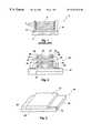
- FIG. 3is a perspective view of an embodiment of a single T-interposer of the present invention.
- FIG. 4is a cross-sectional view of multiple semiconductor devices mounted to an embodiment of a T-interposer according to the present invention
- FIG. 5is a cross-sectional diagram of another embodiment of T-interposers having differing dimensions of the present invention.
- FIG. 6is a perspective view of an embodiment of an inverted T-interposer of the present invention.
- FIG. 7is a cross-sectional view of a multiple semiconductor devices (die) package that has a sealant about the interconnections;
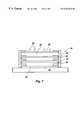
- FIG. 8is a cross-sectional view of another embodiment of the T-interposer of the present invention in a stacked configuration
- FIG. 9is a cross-sectional view of another embodiment of the T-interposer of the present invention in a stacked configuration.
- FIG. 10is a block diagram of an electronic system incorporating the semiconductor device of FIG. 2 and present invention.
- FIG. 2Illustrated in a cross-sectional diagram in drawing FIG. 2 is a multi-stacked semiconductor device structure utilizing a T-interposer device having a T-shape in cross-section of the present invention.
- Multiple stack unit 20comprises a substrate 22 , a first semiconductor device 24 disposed on substrate 22 , a first T-interposer 26 disposed on the first semiconductor device 24 , and multiple semiconductor devices 24 disposed on multiple T-interposers 26 .
- Each semiconductor device 24includes a plurality of bond pads 28 thereon.
- Each T-interposer 26includes a substantially vertical stem 27 having substantially vertical edges and T-bar cross portions or members 29 having substantially horizontal edges or surfaces with respect to the vertical edges of the stem 27 , the upper surface 29 ′ of the T-bar members 29 extending across the stem 27 to form a substantially horizontal surface with respect to the vertical upon which to mount one or more semiconductor devices 24 .
- the flange (horizontal) edges or surfaces of each T-interposer 26are offset so that a portion of the active surface 25 of each semiconductor device 24 attaches to the base of the stem 27 of an adjacent T-interposer 26 while bond pads 28 of each semiconductor device 24 are exposed for wire bonding to substrate 22 or another semiconductor device 24 or the circuit of another T-interposer 26 .
- Each semiconductor device 24is subsequently stacked one on top of another in a horizontal plane with a T-interposer 26 disposed between each semiconductor device 24 .
- Each semiconductor device 24may be bonded either to the T-interposer 26 , another semiconductor device 24 , or to substrate 22 or both.
- the T-interposer 26is placed on an individual semiconductor device 24 as other semiconductor devices 24 are stacked one on top of another, each stacked device 24 being located in a separate substantially horizontal plane. This provides for access and protection to bond pads 28 of the semiconductor devices 24 .
- the T-interposer 26can be made of a variety of materials, including those materials having a coefficient of thermal expansion (CTE) matching or similar to the semiconductor device(s) 24 , such as silicon, ceramic, alloy 42 , etc.
- CTEcoefficient of thermal expansion
- the material for the T-interposer 26may be selected for thermal energy insulation effects to prevent thermal energy from being transferred from one semiconductor device 24 connected to the T-interposer to another semiconductor device 24 connected to the T-interposer.
- the interconnection between semiconductor devices 24 or interposers 26 or substrates 22 , or both,uses conductor traces, tape, wire bonding, conductive paste, or conductive adhesives, or any other type of suitable semiconductor interconnection technique known to one skilled in the art.
- the T-interposer 26allows bond pads 28 of the semiconductor device 24 to be exposed, so no additional rerouting steps are required to reroute a bond pad 28 to the edges. This is advantageous over the prior art structures, such as the cubic design shown in drawing FIG. 1, in that the shell case or the interconnection requires additional processing in those materials and time.
- the flanged edges forming the stem 27 of T-interposer 26allow direct connection to the bond pads 28 and contact to all four sides of semiconductor devices 24 . This allows increased interconnect density between a substrate and a plurality of semiconductor devices.
- the first semiconductor device 24which is mounted to substrate 22 , can be a microprocessor while the second semiconductor device 24 , located above T-interposer 26 mounted to the first semiconductor device 24 located on the substrate 22 , can be a semiconductor memory device, which allows for mixing and matching of the semiconductor devices such as memory devices and processing devices and control logic devices for a complete, integrated semiconductor device package.
- T-interposer 26can be manufactured to match the same CTE of the semiconductor device 24 or the semiconductor device substrate 22 used for each of semiconductor devices 24 , or both. This allows T-interposer 26 to serve as a thermal or heat dissipation device between each semiconductor device 24 while allowing for greater heat dissipation than would otherwise be possible were the semiconductor devices 24 stacked directly upon each other. Further, T-interposer 26 provides electrical insulation between each semiconductor device 24 that would not be otherwise possible were the semiconductor devices to be stacked one upon another such as in the prior art described in drawing FIG. 1 .
- the T-interposer 26may be comprised of two different materials to provide both thermal conductivity from one semiconductor device and thermal insulation with respect to a second semiconductor device.
- the stem 27may be of a thermally conductive material while the T-members 29 are formed of a thermally insulative material, the stem 27 may be joined to the T-member(s) 29 by any suitable means, such as adhesive bonding, etc.
- the T-interposer 26 of the present inventionprovides for much greater bonding edge relief for different types of connection devices with respect to the bond pad location on the active surface of the semiconductor device 24 than that shown in the prior art device illustrated in drawing FIG. 1 and greater insulation capacity for the bond pads 28 of the semiconductor devices 24 with the T-interposer 26 in place.
- a top T-interposer 26is further provided for capping the device to protect and promote heat transfer from the last semiconductor device 24 forming the multi-stack unit 20 .
- an electrical bonding interconnect element 30is manufactured into T-interposer 26 to provide subsequent connection should the bond pads 28 on active surface 25 of the semiconductor device 24 be mounted or connected to the T-shaped interposer 26 for electrical interconnection.
- T-interposer 26is mounted to a substrate 36 .
- Substrate 36includes bonding pads/circuits 28 thereon.
- Semiconductor device 38can be a processor type semiconductor device while semiconductor device 40 can be a memory type semiconductor device.
- Semiconductor device 38 and semiconductor device 40are interconnected via bond pads 28 and further connected to pads or circuits 28 on substrate 36 .
- the bonding wire from one pad or circuit 28can connect directly to the device structure to which the substrate 36 is to be permanently mounted. This can be the actual circuit board, such as a mother board used in a computer system. Of course, other direct connection options will be readily apparent to one skilled in the art.
- FIG. 5illustrated is a cross-sectional diagram of an arrangement of multiple semiconductor device 24 similar to that illustrated in drawing FIG. 4 .
- the present invention illustrated in drawing FIG. 5further adds multiple stacking upon a particular semiconductor device 24 .
- Multiple T-interposers 26are provided and are of similar sizes.
- semiconductor device 24can be directly connected to T-interposer 26 below bond pad 28 thereon.
- substrate 36mounts directly to mother board substrate 22 where additional bond pads are provided in substrates 22 and 36 .
- T-interposer 126of the present invention, which is similar to the embodiment of the T-interposer 26 illustrated in drawing FIG. 3 .
- the T-interposer 126includes additional recessed sections all around. The entire recessed periphery allows semiconductor devices that have connection pads around the entire perimeter of the device to be exposed for connection. In this manner, greater inter-connectivity is achieved with the ability to connect very dense interconnected circuit devices to other semiconductor devices. Additionally, ball weld spots 128 are provided as well and allow direct electrical and mechanical connection of any subsequent semiconductor devices.
- the stem 127 of the T-interposer 126includes T-members 129 therearound and substantially horizontal surface 129 ′ located thereabove as described herein before with respect to T-interposer 26 .
- FIG. 7illustrated is a cross-sectional view of a multiple stack unit 20 that is completely sealed or packaged.
- a substrate 22is provided upon which a first semiconductor device 24 is mounted with an T-interposer 26 mounted to the first semiconductor device 24 .
- a final cap or top T-interposer 26is further provided on top of the entire stack unit 20 .
- an epoxy interconnect 50is provided for sealing and/or packaging and electrically isolating the bonding performed between the multiple semiconductor devices 24 .
- the top of the unit 20may include a heat sink 52 of suitable type material which may include one or more fins 54 (shown in dashed lines) for additional thermal control of the heat from the unit 20 .
- one T-member 29has a greater length or extends farther than the opposing T-member 29 of the T-interposer 26 to provide greater bonding edge relief for different types of connection devices with respect to the bond pad location on the active surface of the semiconductor device 24 than the bonding edge relief provided by the T-member 29 on the other side of the T-interposer 26 .
- the T-interposer 26is not centrally located on a portion of the active surface of the semiconductor device 40 but, rather, is located off-center on a portion of the active surface of the semiconductor device 40 .
- Such a T-interposer 26allows for the accommodation of differing sizes and shapes of semiconductor devices 40 and bond pad arrangements thereon for interconnection to the circuits 58 of substrate 36 .
- the T-interposer 26includes a plurality of stems 27 and T-members 29 to form the same, each stem 27 located on a portion of the active surface of a semiconductor device 40 which is, in turn, located on a substrate 36 having circuits 58 located thereon connected by wires 56 while wires 62 electrically connect the semiconductor devices 40 located on surface 29 ′ of the T-interposer 26 to the circuits 60 located thereon.
- the T-interposer 26helps to increase the density of the semiconductor devices 40 located on the substrate 36 while providing thermal control of the heat generated from the semiconductor devices 40 located on the substrate 36 and on the surface 29 ′ of the T-interposer 26 .
- Each T-interposer 26can be manufactured in various manners; ideally, the T-interposer 26 consists of a unitary element that is milled or machined from a single piece. The side edges for producing the “T” effect are milled away to preserve the integral strength of the unitary piece. This design prevents fractures occurring in seams of the T-interposer where the top “T” portion is epoxied to the bottom as a separate element. If desired, T-interposer 26 can be made from separate pieces, one having a smaller width than the other, if the epoxy or adhesive used to connect the two elements is of sufficient strength to prevent fracturing or separation, or the strain and load placed on the seams were greatly reduced so as to minimize the possibility of fracturing.
- the use of the T-interposer 26 for stacking bare dieshas several advantages over prior art solutions.
- One advantageis that it reduces stack stresses or bending.
- the T-interposerallows easier reworking of any bond interconnect when necessary.
- there is no stress problems inherit in stacking semiconductor devices upon other devicesas any number of devices can be stacked with T-interposer 26 used in separating device from device, thus allowing for greater device densities for memory devices and other type semiconductor devices.
- several types of interconnect methodsare possible with the T-interposer, such as wire bonding, ball bonding, flip chip bonding, etc. Additional advantages include the bond pads of each semiconductor device being protected from one another in the device stack. Thermal and mechanical properties are improved because of the use of the T-interposer. The improved thermal and mechanical properties also allow for increased semiconductor device density for memory chips and SIMM type devices.
- semiconductor devicesmay comprise an integrated circuit die employed for storing or processing digital information, including, for example, a Dynamic Random Access Memory (DRAM) integrated circuit die, a Static Random Access Memory (SRAM) integrated circuit die, a Synchronous Graphics Random Access Memory (SGRAM) integrated circuit die, a Programmable Read-Only Memory (PROM) integrated circuit die, an Electrically Erasable PROM (EEPROM) integrated circuit die, a flash memory die and a microprocessor die, and that the present invention includes such devices within its scope.
- DRAMDynamic Random Access Memory
- SRAMStatic Random Access Memory
- SGRAMSynchronous Graphics Random Access Memory
- PROMProgrammable Read-Only Memory
- EEPROMElectrically Erasable PROM
- the jumper padsmay be round, oblong, hemispherical or variously shaped and sized so long as the jumper pads provide enough surface area to accept attachment of one or more wire bonds thereto.
- the bond padsmay be positioned at any location on the active surface of the die.
- an electronic system 130includes an input device 132 and an output device 134 coupled to a processor device 136 which, in turn, is coupled to a memory device 138 incorporating the exemplary integrated circuit die 12 of drawing FIG. 2 .
Landscapes
- Engineering & Computer Science (AREA)
- Microelectronics & Electronic Packaging (AREA)
- Power Engineering (AREA)
- Physics & Mathematics (AREA)
- Condensed Matter Physics & Semiconductors (AREA)
- General Physics & Mathematics (AREA)
- Computer Hardware Design (AREA)
- Cooling Or The Like Of Semiconductors Or Solid State Devices (AREA)
- Wire Bonding (AREA)
Abstract
Description
Claims (82)
Priority Applications (7)
| Application Number | Priority Date | Filing Date | Title |
|---|---|---|---|
| US09/247,009US6351028B1 (en) | 1999-02-08 | 1999-02-08 | Multiple die stack apparatus employing T-shaped interposer elements |
| US09/989,341US6730543B2 (en) | 1999-02-08 | 2001-11-20 | Methods for multiple die stack apparatus employing |
| US09/989,326US6911723B2 (en) | 1999-02-08 | 2001-11-20 | Multiple die stack apparatus employing T-shaped interposer elements |
| US10/933,843US7064006B2 (en) | 1999-02-08 | 2004-09-02 | Multiple die stack apparatus employing T-shaped interposer elements |
| US11/302,005US7282793B2 (en) | 1999-02-08 | 2005-12-13 | Multiple die stack apparatus employing T-shaped interposer elements |
| US11/302,304US7282794B2 (en) | 1999-02-08 | 2005-12-13 | Multiple die stack apparatus employing t-shaped interposer elements |
| US11/840,815US7518227B2 (en) | 1999-02-08 | 2007-08-17 | Multiple die stack apparatus employing T-shaped interposer elements |
Applications Claiming Priority (1)
| Application Number | Priority Date | Filing Date | Title |
|---|---|---|---|
| US09/247,009US6351028B1 (en) | 1999-02-08 | 1999-02-08 | Multiple die stack apparatus employing T-shaped interposer elements |
Related Child Applications (2)
| Application Number | Title | Priority Date | Filing Date |
|---|---|---|---|
| US09/989,326ContinuationUS6911723B2 (en) | 1999-02-08 | 2001-11-20 | Multiple die stack apparatus employing T-shaped interposer elements |
| US09/989,341DivisionUS6730543B2 (en) | 1999-02-08 | 2001-11-20 | Methods for multiple die stack apparatus employing |
Publications (1)
| Publication Number | Publication Date |
|---|---|
| US6351028B1true US6351028B1 (en) | 2002-02-26 |
Family
ID=22933157
Family Applications (7)
| Application Number | Title | Priority Date | Filing Date |
|---|---|---|---|
| US09/247,009Expired - LifetimeUS6351028B1 (en) | 1999-02-08 | 1999-02-08 | Multiple die stack apparatus employing T-shaped interposer elements |
| US09/989,326Expired - LifetimeUS6911723B2 (en) | 1999-02-08 | 2001-11-20 | Multiple die stack apparatus employing T-shaped interposer elements |
| US09/989,341Expired - Fee RelatedUS6730543B2 (en) | 1999-02-08 | 2001-11-20 | Methods for multiple die stack apparatus employing |
| US10/933,843Expired - LifetimeUS7064006B2 (en) | 1999-02-08 | 2004-09-02 | Multiple die stack apparatus employing T-shaped interposer elements |
| US11/302,304Expired - Fee RelatedUS7282794B2 (en) | 1999-02-08 | 2005-12-13 | Multiple die stack apparatus employing t-shaped interposer elements |
| US11/302,005Expired - Fee RelatedUS7282793B2 (en) | 1999-02-08 | 2005-12-13 | Multiple die stack apparatus employing T-shaped interposer elements |
| US11/840,815Expired - Fee RelatedUS7518227B2 (en) | 1999-02-08 | 2007-08-17 | Multiple die stack apparatus employing T-shaped interposer elements |
Family Applications After (6)
| Application Number | Title | Priority Date | Filing Date |
|---|---|---|---|
| US09/989,326Expired - LifetimeUS6911723B2 (en) | 1999-02-08 | 2001-11-20 | Multiple die stack apparatus employing T-shaped interposer elements |
| US09/989,341Expired - Fee RelatedUS6730543B2 (en) | 1999-02-08 | 2001-11-20 | Methods for multiple die stack apparatus employing |
| US10/933,843Expired - LifetimeUS7064006B2 (en) | 1999-02-08 | 2004-09-02 | Multiple die stack apparatus employing T-shaped interposer elements |
| US11/302,304Expired - Fee RelatedUS7282794B2 (en) | 1999-02-08 | 2005-12-13 | Multiple die stack apparatus employing t-shaped interposer elements |
| US11/302,005Expired - Fee RelatedUS7282793B2 (en) | 1999-02-08 | 2005-12-13 | Multiple die stack apparatus employing T-shaped interposer elements |
| US11/840,815Expired - Fee RelatedUS7518227B2 (en) | 1999-02-08 | 2007-08-17 | Multiple die stack apparatus employing T-shaped interposer elements |
Country Status (1)
| Country | Link |
|---|---|
| US (7) | US6351028B1 (en) |
Cited By (91)
| Publication number | Priority date | Publication date | Assignee | Title |
|---|---|---|---|---|
| US20010055838A1 (en)* | 2000-04-28 | 2001-12-27 | Matrix Semiconductor Inc. | Nonvolatile memory on SOI and compound semiconductor substrates and method of fabrication |
| US20020028541A1 (en)* | 2000-08-14 | 2002-03-07 | Lee Thomas H. | Dense arrays and charge storage devices, and methods for making same |
| US20020116668A1 (en)* | 2001-02-20 | 2002-08-22 | Matrix Semiconductor, Inc. | Memory card with enhanced testability and methods of making and using the same |
| US20020125580A1 (en)* | 2001-03-01 | 2002-09-12 | Advanced Semiconductor Engineering, Inc. | Stacked semiconductor chip package |
| US6483736B2 (en)* | 1998-11-16 | 2002-11-19 | Matrix Semiconductor, Inc. | Vertically stacked field programmable nonvolatile memory and method of fabrication |
| US6503776B2 (en)* | 2001-01-05 | 2003-01-07 | Advanced Semiconductor Engineering, Inc. | Method for fabricating stacked chip package |
| US20030030074A1 (en)* | 2001-08-13 | 2003-02-13 | Walker Andrew J | TFT mask ROM and method for making same |
| US6525953B1 (en) | 2001-08-13 | 2003-02-25 | Matrix Semiconductor, Inc. | Vertically-stacked, field-programmable, nonvolatile memory and method of fabrication |
| US20030038357A1 (en)* | 2001-08-24 | 2003-02-27 | Derderian James M. | Spacer for semiconductor devices, semiconductor devices and assemblies including the spacer, and methods |
| US6555902B2 (en)* | 2000-07-17 | 2003-04-29 | Siliconware Precision Industries Co., Ltd. | Multiple stacked-chip packaging structure |
| US20030111737A1 (en)* | 2001-06-07 | 2003-06-19 | Mitsuaki Katagiri | Semiconductor device and a method of manufacturing the same |
| US6593624B2 (en) | 2001-09-25 | 2003-07-15 | Matrix Semiconductor, Inc. | Thin film transistors with vertically offset drain regions |
| US20030148597A1 (en)* | 2002-01-09 | 2003-08-07 | Tan Hock Chuan | Stacked die in die BGA package |
| US20030173643A1 (en)* | 2002-03-13 | 2003-09-18 | Matrix Semiconductor, Inc. | Silicide-silicon oxide-semiconductor antifuse device and method of making |
| US6624485B2 (en) | 2001-11-05 | 2003-09-23 | Matrix Semiconductor, Inc. | Three-dimensional, mask-programmed read only memory |
| US20030189259A1 (en)* | 2002-04-05 | 2003-10-09 | Nec Electronics Corporation | Semiconductor device and method for manufacturing the same |
| US20030197261A1 (en)* | 2002-04-20 | 2003-10-23 | Samsung Electronics Co., Ltd. | Memory card |
| US6710455B2 (en)* | 2001-08-30 | 2004-03-23 | Infineon Technologies Ag | Electronic component with at least two stacked semiconductor chips and method for fabricating the electronic component |
| US6731011B2 (en) | 2002-02-19 | 2004-05-04 | Matrix Semiconductor, Inc. | Memory module having interconnected and stacked integrated circuits |
| US6737675B2 (en) | 2002-06-27 | 2004-05-18 | Matrix Semiconductor, Inc. | High density 3D rail stack arrays |
| US20040113250A1 (en)* | 2002-12-12 | 2004-06-17 | Khandros Igor Y. | Integrated circuit assembly |
| US6759745B2 (en)* | 2001-09-13 | 2004-07-06 | Texas Instruments Incorporated | Semiconductor device and manufacturing method thereof |
| US6777797B2 (en)* | 2002-06-27 | 2004-08-17 | Oki Electric Industry. Co., Ltd. | Stacked multi-chip package, process for fabrication of chip structuring package, and process for wire-bonding |
| US20040184250A1 (en)* | 2003-03-21 | 2004-09-23 | Advanced Semiconductor Engineering, Inc. | Multi-chips stacked package |
| US20040207001A1 (en)* | 2001-03-28 | 2004-10-21 | Matrix Semiconductor, Inc. | Two mask floating gate EEPROM and method of making |
| US20040214372A1 (en)* | 2003-04-07 | 2004-10-28 | Walter Moden | Method for fabricating image sensor semiconductor package |
| US20040232488A1 (en)* | 2003-05-21 | 2004-11-25 | Micron Technology, Inc. | Silicon oxycarbide substrates for bonded silicon on insulator |
| US20040232487A1 (en)* | 2003-05-21 | 2004-11-25 | Micron Technology, Inc. | Ultra-thin semiconductors bonded on glass substrates |
| US20040241907A1 (en)* | 2003-05-30 | 2004-12-02 | Tomoko Higashino | Method of manufacturing a semiconductor device |
| US6836002B2 (en)* | 2000-03-09 | 2004-12-28 | Sharp Kabushiki Kaisha | Semiconductor device |
| US6843421B2 (en) | 2001-08-13 | 2005-01-18 | Matrix Semiconductor, Inc. | Molded memory module and method of making the module absent a substrate support |
| US20050026395A1 (en)* | 2002-01-16 | 2005-02-03 | Micron Technology, Inc. | Fabrication of stacked microelectronic devices |
| US20050029619A1 (en)* | 2003-08-05 | 2005-02-10 | Micron Technology, Inc. | Strained Si/SiGe/SOI islands and processes of making same |
| US20050074966A1 (en)* | 1999-09-02 | 2005-04-07 | Micron Technology, Inc. | Local multilayered metallization |
| US20050104206A1 (en)* | 2003-11-13 | 2005-05-19 | Jeong-Hyeon Cho | Mounting structure in integrated circuit module |
| US20050156303A1 (en)* | 2004-01-21 | 2005-07-21 | Kai-Chiang Wu | Structure of gold fingers |
| US20050161797A1 (en)* | 2001-10-03 | 2005-07-28 | Formfactor, Inc. | Multiple die interconnect system |
| US6933597B1 (en)* | 2002-07-09 | 2005-08-23 | National Semiconductor Corporation | Spacer with passive components for use in multi-chip modules |
| US20050196941A1 (en)* | 2004-03-02 | 2005-09-08 | Chippac, Inc. | DBG system and method with adhesive layer severing |
| US20050200003A1 (en)* | 2004-01-13 | 2005-09-15 | Ki-Myung Yoon | Multi-chip package |
| US20050208700A1 (en)* | 2004-03-19 | 2005-09-22 | Chippac, Inc. | Die to substrate attach using printed adhesive |
| US20050208701A1 (en)* | 2004-03-02 | 2005-09-22 | Chippac, Inc. | Semiconductor chip packaging method with individually placed film adhesive pieces |
| US20050218479A1 (en)* | 2004-04-01 | 2005-10-06 | Chippac, Inc. | Spacer die structure and method for attaching |
| US20050224959A1 (en)* | 2004-04-01 | 2005-10-13 | Chippac, Inc | Die with discrete spacers and die spacing method |
| US20050224919A1 (en)* | 2004-04-01 | 2005-10-13 | Chippac, Inc | Spacer die structure and method for attaching |
| US20050230800A1 (en)* | 2004-04-16 | 2005-10-20 | St Assembly Test Services Ltd. | Thermally enhanced stacked die package and fabrication method |
| US20050258545A1 (en)* | 2004-05-24 | 2005-11-24 | Chippac, Inc. | Multiple die package with adhesive/spacer structure and insulated die surface |
| US20050258527A1 (en)* | 2004-05-24 | 2005-11-24 | Chippac, Inc. | Adhesive/spacer island structure for multiple die package |
| US20050269676A1 (en)* | 2004-05-24 | 2005-12-08 | Chippac, Inc | Adhesive/spacer island structure for stacking over wire bonded die |
| US20060051896A1 (en)* | 2004-09-09 | 2006-03-09 | Meadows Paul M | Stacking circuit elements |
| US20060071315A1 (en)* | 2001-03-09 | 2006-04-06 | Oh Kwang S | Method of forming a stacked semiconductor package |
| US20060076690A1 (en)* | 2004-09-27 | 2006-04-13 | Formfactor, Inc. | Stacked Die Module |
| US7037756B1 (en) | 2001-08-30 | 2006-05-02 | Micron Technology, Inc. | Stacked microelectronic devices and methods of fabricating same |
| US20060157866A1 (en)* | 2005-01-20 | 2006-07-20 | Le Thoai T | Signal redistribution using bridge layer for multichip module |
| US20060170088A1 (en)* | 2005-02-01 | 2006-08-03 | Taiwan Semiconductor Manufacturing Company, Ltd. | Spacer Structures for Semiconductor Package Devices |
| US20060175697A1 (en)* | 2005-02-02 | 2006-08-10 | Tetsuya Kurosawa | Semiconductor device having semiconductor chips stacked and mounted thereon and manufacturing method thereof |
| US20070018296A1 (en)* | 2004-05-24 | 2007-01-25 | Chippac, Inc | Stacked Semiconductor Package having Adhesive/Spacer Structure and Insulation |
| US20070040260A1 (en)* | 2005-08-18 | 2007-02-22 | Ralf Otremba | Power semiconductor device comprising a semiconductor chip stack and method for producing the same |
| US20070108621A1 (en)* | 2005-08-10 | 2007-05-17 | Stats Chippac Ltd. | Integrated circuit package system with arched pedestal |
| US20070132080A1 (en)* | 2003-10-20 | 2007-06-14 | Moriyoshi Nakashima | Semiconductor chip mounted interposer, semiconductor device, semiconductor chip interposer fabrication method, bare chip mounted interposer, and interposer sheet |
| US20070178666A1 (en)* | 2006-01-31 | 2007-08-02 | Stats Chippac Ltd. | Integrated circuit system with waferscale spacer system |
| US20070176275A1 (en)* | 2006-01-27 | 2007-08-02 | Singleton Laurence E | Stack of semiconductor chips |
| US20080237824A1 (en)* | 2006-02-17 | 2008-10-02 | Amkor Technology, Inc. | Stacked electronic component package having single-sided film spacer |
| US20080303133A1 (en)* | 2007-06-07 | 2008-12-11 | Henry Descalzo Bathan | Integrated circuit package system with contoured die |
| US20090014857A1 (en)* | 2007-07-13 | 2009-01-15 | Erich Hufgard | Semiconductor wafer structure |
| US20090032969A1 (en)* | 2007-07-30 | 2009-02-05 | Camillo Pilla | Arrangement of Integrated Circuit Dice and Method for Fabricating Same |
| US20090065948A1 (en)* | 2007-09-06 | 2009-03-12 | Micron Technology, Inc. | Package structure for multiple die stack |
| US20090091042A1 (en)* | 2007-10-04 | 2009-04-09 | Byung Tai Do | Integrated circuit package system including die having relieved active region |
| US20090096110A1 (en)* | 2007-10-12 | 2009-04-16 | Kabushiki Kaisha Toshiba | Method for manufacturing a stacked semiconductor package, and stacked semiconductor package |
| US20090227069A1 (en)* | 2008-03-06 | 2009-09-10 | Commissariat A L'energie Atomique | Method and device for fabricating an assembly of at least two microelectronic chips |
| US20090256243A1 (en)* | 2002-03-25 | 2009-10-15 | Micron Technology, Inc. | Low k interconnect dielectric using surface transformation |
| US7633144B1 (en) | 2006-05-24 | 2009-12-15 | Amkor Technology, Inc. | Semiconductor package |
| US20090321950A1 (en)* | 2008-06-30 | 2009-12-31 | Hem Takiar | Stacked semiconductor package with localized cavities for wire bonding |
| US20090325342A1 (en)* | 2008-06-30 | 2009-12-31 | Hem Takiar | Method of fabricating stacked semiconductor package with localized cavities for wire bonding |
| US7675180B1 (en)* | 2006-02-17 | 2010-03-09 | Amkor Technology, Inc. | Stacked electronic component package having film-on-wire spacer |
| US20100246144A1 (en)* | 2006-01-25 | 2010-09-30 | Nec Corporation | Electronic device package, module, and electronic device |
| US20110095407A1 (en)* | 2008-10-20 | 2011-04-28 | Micron Technology, Inc. | Stackable semiconductor assemblies and methods of manufacturing such assemblies |
| US20110175206A1 (en)* | 2007-08-28 | 2011-07-21 | Micron Technology, Inc. | Semiconductor assemblies and methods of manufacturing such assemblies |
| US8575719B2 (en) | 2000-04-28 | 2013-11-05 | Sandisk 3D Llc | Silicon nitride antifuse for use in diode-antifuse memory arrays |
| WO2014041107A1 (en)* | 2012-09-17 | 2014-03-20 | Commissariat A L'energie Atomique Et Aux Energies Alternatives | Cap for a chip device having a groove, device provided with said cap, assembly consisting of the device and a wire element, and manufacturing method thereof |
| US9478495B1 (en) | 2015-10-26 | 2016-10-25 | Sandisk Technologies Llc | Three dimensional memory device containing aluminum source contact via structure and method of making thereof |
| US9627395B2 (en) | 2015-02-11 | 2017-04-18 | Sandisk Technologies Llc | Enhanced channel mobility three-dimensional memory structure and method of making thereof |
| US20170133349A1 (en)* | 2015-11-11 | 2017-05-11 | Freescale Semiconductor, Inc. | Method of packaging integrated circuit die and device |
| US9768098B2 (en)* | 2014-12-23 | 2017-09-19 | Texas Instruments Incorporated | Packaged semiconductor device having stacked attached chips overhanging the assembly pad |
| US20170301598A1 (en)* | 2005-08-19 | 2017-10-19 | Micron Technology, Inc. | Microelectronic devices, stacked microelectronic devices, and methods for manufacturing microelectronic devices |
| US20200133907A1 (en)* | 2018-10-31 | 2020-04-30 | Dell Products L.P. | Interposer systems for information handling systems |
| US11309301B2 (en) | 2020-05-28 | 2022-04-19 | Sandisk Technologies Llc | Stacked die assembly including double-sided inter-die bonding connections and methods of forming the same |
| US11335671B2 (en)* | 2020-05-28 | 2022-05-17 | Sandisk Technologies Llc | Stacked die assembly including double-sided inter-die bonding connections and methods of forming the same |
| US11452209B2 (en)* | 2020-01-10 | 2022-09-20 | Tdk Corporation | Electronic component and its manufacturing method |
| US11545303B2 (en)* | 2020-01-16 | 2023-01-03 | Tdk Corporation | Electronic component and its manufacturing method |
| US12015005B2 (en) | 2021-06-25 | 2024-06-18 | Samsung Electronics Co., Ltd. | Semiconductor package including non-conductive film and method for forming the same |
Families Citing this family (55)
| Publication number | Priority date | Publication date | Assignee | Title |
|---|---|---|---|---|
| US6351028B1 (en)* | 1999-02-08 | 2002-02-26 | Micron Technology, Inc. | Multiple die stack apparatus employing T-shaped interposer elements |
| JP3913481B2 (en)* | 2001-01-24 | 2007-05-09 | シャープ株式会社 | Semiconductor device and manufacturing method of semiconductor device |
| US6586825B1 (en)* | 2001-04-26 | 2003-07-01 | Lsi Logic Corporation | Dual chip in package with a wire bonded die mounted to a substrate |
| US7021520B2 (en)* | 2001-12-05 | 2006-04-04 | Micron Technology, Inc. | Stacked chip connection using stand off stitch bonding |
| US8089142B2 (en)* | 2002-02-13 | 2012-01-03 | Micron Technology, Inc. | Methods and apparatus for a stacked-die interposer |
| US6861288B2 (en)* | 2003-01-23 | 2005-03-01 | St Assembly Test Services, Ltd. | Stacked semiconductor packages and method for the fabrication thereof |
| JP3846437B2 (en)* | 2003-03-17 | 2006-11-15 | 株式会社日立製作所 | Automotive control unit |
| US7242101B2 (en)* | 2004-07-19 | 2007-07-10 | St Assembly Test Services Ltd. | Integrated circuit die with pedestal |
| US7215031B2 (en)* | 2004-11-10 | 2007-05-08 | Oki Electric Industry Co., Ltd. | Multi chip package |
| KR100593703B1 (en)* | 2004-12-10 | 2006-06-30 | 삼성전자주식회사 | Semiconductor chip stack package with dummy chips for reinforcing protrusion wire bonding structure |
| US7067927B1 (en)* | 2005-01-31 | 2006-06-27 | National Semiconductor Corporation | Die with integral pedestal having insulated walls |
| US7446396B2 (en)* | 2005-02-10 | 2008-11-04 | Stats Chippac Ltd. | Stacked integrated circuit leadframe package system |
| US7163839B2 (en)* | 2005-04-27 | 2007-01-16 | Spansion Llc | Multi-chip module and method of manufacture |
| KR100653605B1 (en)* | 2005-11-15 | 2006-12-06 | 삼성전자주식회사 | Semiconductor chip package having a metal core heat sink and a semiconductor module comprising the same |
| US20070126085A1 (en)* | 2005-12-02 | 2007-06-07 | Nec Electronics Corporation | Semiconductor device and method of manufacturing the same |
| US20070263425A1 (en)* | 2006-02-08 | 2007-11-15 | Qimonda Ag | Memory arrangement |
| US7498667B2 (en)* | 2006-04-18 | 2009-03-03 | Stats Chippac Ltd. | Stacked integrated circuit package-in-package system |
| SG136822A1 (en)* | 2006-04-19 | 2007-11-29 | Micron Technology Inc | Integrated circuit devices with stacked package interposers |
| US7420206B2 (en)* | 2006-07-12 | 2008-09-02 | Genusion Inc. | Interposer, semiconductor chip mounted sub-board, and semiconductor package |
| JP5006640B2 (en)* | 2006-12-22 | 2012-08-22 | 新光電気工業株式会社 | Manufacturing method of semiconductor device |
| US7508070B2 (en)* | 2007-01-13 | 2009-03-24 | Cheng-Lien Chiang | Two dimensional stacking using interposers |
| CN101467251A (en)* | 2007-06-01 | 2009-06-24 | 松下电器产业株式会社 | Semiconductor device |
| JP2009026884A (en)* | 2007-07-18 | 2009-02-05 | Elpida Memory Inc | Circuit module and electric component |
| SG149725A1 (en)* | 2007-07-24 | 2009-02-27 | Micron Technology Inc | Thin semiconductor die packages and associated systems and methods |
| SG149724A1 (en)* | 2007-07-24 | 2009-02-27 | Micron Technology Inc | Semicoductor dies with recesses, associated leadframes, and associated systems and methods |
| KR20090022433A (en)* | 2007-08-30 | 2009-03-04 | 삼성전자주식회사 | Semiconductor package |
| KR101413220B1 (en)* | 2007-10-02 | 2014-06-30 | 삼성전자주식회사 | Semiconductor package having interposer and method for manufacturing semiconductor package |
| US8536692B2 (en)* | 2007-12-12 | 2013-09-17 | Stats Chippac Ltd. | Mountable integrated circuit package system with mountable integrated circuit die |
| US7985628B2 (en)* | 2007-12-12 | 2011-07-26 | Stats Chippac Ltd. | Integrated circuit package system with interconnect lock |
| US7781261B2 (en)* | 2007-12-12 | 2010-08-24 | Stats Chippac Ltd. | Integrated circuit package system with offset stacking and anti-flash structure |
| US8084849B2 (en)* | 2007-12-12 | 2011-12-27 | Stats Chippac Ltd. | Integrated circuit package system with offset stacking |
| US20090243069A1 (en)* | 2008-03-26 | 2009-10-01 | Zigmund Ramirez Camacho | Integrated circuit package system with redistribution |
| US7821107B2 (en)* | 2008-04-22 | 2010-10-26 | Micron Technology, Inc. | Die stacking with an annular via having a recessed socket |
| US9293385B2 (en)* | 2008-07-30 | 2016-03-22 | Stats Chippac Ltd. | RDL patterning with package on package system |
| KR20100056247A (en)* | 2008-11-19 | 2010-05-27 | 삼성전자주식회사 | Semiconductor package having adhesive layer |
| US7943428B2 (en)* | 2008-12-24 | 2011-05-17 | International Business Machines Corporation | Bonded semiconductor substrate including a cooling mechanism |
| US7863106B2 (en)* | 2008-12-24 | 2011-01-04 | International Business Machines Corporation | Silicon interposer testing for three dimensional chip stack |
| US8222726B2 (en)* | 2010-03-29 | 2012-07-17 | Advanced Semiconductor Engineering, Inc. | Semiconductor device package having a jumper chip and method of fabricating the same |
| US8466563B2 (en) | 2010-05-19 | 2013-06-18 | The Johns Hopkins University | Apparatus and methods for 3-D stacking of thinned die |
| KR20110138945A (en)* | 2010-06-22 | 2011-12-28 | 하나 마이크론(주) | Stacked Semiconductor Packages |
| JP2013529850A (en)* | 2010-07-05 | 2013-07-22 | モサイド・テクノロジーズ・インコーポレーテッド | Multi-chip package with thermal frame and assembly method |
| US8687378B2 (en)* | 2011-10-17 | 2014-04-01 | Murata Manufacturing Co., Ltd. | High-frequency module |
| US8905632B2 (en) | 2011-11-29 | 2014-12-09 | Cisco Technology, Inc. | Interposer configuration with thermally isolated regions for temperature-sensitive opto-electronic components |
| JP2014533895A (en)* | 2011-11-29 | 2014-12-15 | コンバーサント・インテレクチュアル・プロパティ・マネジメント・インコーポレイテッドConversant Intellectual Property Management Inc. | Interposer for stacked semiconductor devices |
| US20130157414A1 (en)* | 2011-12-20 | 2013-06-20 | Nxp B. V. | Stacked-die package and method therefor |
| US20140326856A1 (en)* | 2013-05-06 | 2014-11-06 | Omnivision Technologies, Inc. | Integrated circuit stack with low profile contacts |
| JP6560496B2 (en)* | 2015-01-26 | 2019-08-14 | 株式会社ジェイデバイス | Semiconductor device |
| US10090259B2 (en)* | 2015-12-26 | 2018-10-02 | Intel Corporation | Non-rectangular electronic device components |
| KR102442622B1 (en)* | 2017-08-03 | 2022-09-13 | 삼성전자주식회사 | Semiconductor device package |
| CN107579048A (en)* | 2017-09-27 | 2018-01-12 | 江苏长电科技股份有限公司 | A structure and process method for improving multi-chip stacking |
| JP2020021908A (en)* | 2018-08-03 | 2020-02-06 | キオクシア株式会社 | Semiconductor device and method for manufacturing the same |
| US10797035B1 (en) | 2019-04-02 | 2020-10-06 | Sandisk Technologies Llc | Bonded assembly containing side bonding structures and methods of manufacturing the same |
| US11721657B2 (en) | 2019-06-14 | 2023-08-08 | Stmicroelectronics Pte Ltd | Wafer level chip scale package having varying thicknesses |
| KR20220081036A (en)* | 2020-12-08 | 2022-06-15 | 삼성전자주식회사 | Semiconductor package and method of manufacturing the semiconductor package |
| CN116960091A (en)* | 2023-08-08 | 2023-10-27 | 惠州佰维存储科技有限公司 | Chip structure, chip manufacturing method and solid state disk |
Citations (8)
| Publication number | Priority date | Publication date | Assignee | Title |
|---|---|---|---|---|
| JPS63128736A (en)* | 1986-11-19 | 1988-06-01 | Olympus Optical Co Ltd | Semiconductor element |
| US5434745A (en) | 1994-07-26 | 1995-07-18 | White Microelectronics Div. Of Bowmar Instrument Corp. | Stacked silicon die carrier assembly |
| US5515241A (en) | 1992-12-30 | 1996-05-07 | Interconnect Systems, Inc. | Space-saving assemblies for connecting integrated circuits to circuit boards |
| US5569956A (en) | 1995-08-31 | 1996-10-29 | National Semiconductor Corporation | Interposer connecting leadframe and integrated circuit |
| US5585675A (en) | 1994-05-11 | 1996-12-17 | Harris Corporation | Semiconductor die packaging tub having angularly offset pad-to-pad via structure configured to allow three-dimensional stacking and electrical interconnections among multiple identical tubs |
| US5904497A (en)* | 1997-08-22 | 1999-05-18 | Micron Technology, Inc. | Method and apparatus for semiconductor assembly which includes testing of chips and replacement of bad chips prior to final assembly |
| US6005778A (en)* | 1995-06-15 | 1999-12-21 | Honeywell Inc. | Chip stacking and capacitor mounting arrangement including spacers |
| US6028365A (en)* | 1998-03-30 | 2000-02-22 | Micron Technology, Inc. | Integrated circuit package and method of fabrication |
Family Cites Families (8)
| Publication number | Priority date | Publication date | Assignee | Title |
|---|---|---|---|---|
| US5258648A (en)* | 1991-06-27 | 1993-11-02 | Motorola, Inc. | Composite flip chip semiconductor device with an interposer having test contacts formed along its periphery |
| US5790384A (en)* | 1997-06-26 | 1998-08-04 | International Business Machines Corporation | Bare die multiple dies for direct attach |
| US6777965B1 (en)* | 1998-07-28 | 2004-08-17 | Micron Technology, Inc. | Interposer for electrically coupling a semiconductive device to an electrical apparatus |
| US6351028B1 (en)* | 1999-02-08 | 2002-02-26 | Micron Technology, Inc. | Multiple die stack apparatus employing T-shaped interposer elements |
| KR20010056618A (en)* | 1999-12-16 | 2001-07-04 | 프랑크 제이. 마르쿠치 | Semiconductor package |
| TWI278947B (en) | 2004-01-13 | 2007-04-11 | Samsung Electronics Co Ltd | A multi-chip package, a semiconductor device used therein and manufacturing method thereof |
| JP4434778B2 (en) | 2004-02-25 | 2010-03-17 | Necエレクトロニクス株式会社 | Semiconductor device |
| TWI265617B (en)* | 2005-01-11 | 2006-11-01 | Siliconware Precision Industries Co Ltd | Lead-frame-based semiconductor package with lead frame and lead frame thereof |
- 1999
- 1999-02-08USUS09/247,009patent/US6351028B1/ennot_activeExpired - Lifetime
- 2001
- 2001-11-20USUS09/989,326patent/US6911723B2/ennot_activeExpired - Lifetime
- 2001-11-20USUS09/989,341patent/US6730543B2/ennot_activeExpired - Fee Related
- 2004
- 2004-09-02USUS10/933,843patent/US7064006B2/ennot_activeExpired - Lifetime
- 2005
- 2005-12-13USUS11/302,304patent/US7282794B2/ennot_activeExpired - Fee Related
- 2005-12-13USUS11/302,005patent/US7282793B2/ennot_activeExpired - Fee Related
- 2007
- 2007-08-17USUS11/840,815patent/US7518227B2/ennot_activeExpired - Fee Related
Patent Citations (8)
| Publication number | Priority date | Publication date | Assignee | Title |
|---|---|---|---|---|
| JPS63128736A (en)* | 1986-11-19 | 1988-06-01 | Olympus Optical Co Ltd | Semiconductor element |
| US5515241A (en) | 1992-12-30 | 1996-05-07 | Interconnect Systems, Inc. | Space-saving assemblies for connecting integrated circuits to circuit boards |
| US5585675A (en) | 1994-05-11 | 1996-12-17 | Harris Corporation | Semiconductor die packaging tub having angularly offset pad-to-pad via structure configured to allow three-dimensional stacking and electrical interconnections among multiple identical tubs |
| US5434745A (en) | 1994-07-26 | 1995-07-18 | White Microelectronics Div. Of Bowmar Instrument Corp. | Stacked silicon die carrier assembly |
| US6005778A (en)* | 1995-06-15 | 1999-12-21 | Honeywell Inc. | Chip stacking and capacitor mounting arrangement including spacers |
| US5569956A (en) | 1995-08-31 | 1996-10-29 | National Semiconductor Corporation | Interposer connecting leadframe and integrated circuit |
| US5904497A (en)* | 1997-08-22 | 1999-05-18 | Micron Technology, Inc. | Method and apparatus for semiconductor assembly which includes testing of chips and replacement of bad chips prior to final assembly |
| US6028365A (en)* | 1998-03-30 | 2000-02-22 | Micron Technology, Inc. | Integrated circuit package and method of fabrication |
Cited By (256)
| Publication number | Priority date | Publication date | Assignee | Title |
|---|---|---|---|---|
| US7265000B2 (en) | 1998-11-16 | 2007-09-04 | Sandisk 3D Llc | Vertically stacked field programmable nonvolatile memory and method of fabrication |
| US9214243B2 (en) | 1998-11-16 | 2015-12-15 | Sandisk 3D Llc | Three-dimensional nonvolatile memory and method of fabrication |
| US8503215B2 (en) | 1998-11-16 | 2013-08-06 | Sandisk 3D Llc | Vertically stacked field programmable nonvolatile memory and method of fabrication |
| US20110019467A1 (en)* | 1998-11-16 | 2011-01-27 | Johnson Mark G | Vertically stacked field programmable nonvolatile memory and method of fabrication |
| US6483736B2 (en)* | 1998-11-16 | 2002-11-19 | Matrix Semiconductor, Inc. | Vertically stacked field programmable nonvolatile memory and method of fabrication |
| US8897056B2 (en) | 1998-11-16 | 2014-11-25 | Sandisk 3D Llc | Pillar-shaped nonvolatile memory and method of fabrication |
| US20030016553A1 (en)* | 1998-11-16 | 2003-01-23 | Vivek Subramanian | Vertically stacked field programmable nonvolatile memory and method of fabrication |
| US7319053B2 (en) | 1998-11-16 | 2008-01-15 | Sandisk 3D Llc | Vertically stacked field programmable nonvolatile memory and method of fabrication |
| US7283403B2 (en) | 1998-11-16 | 2007-10-16 | Sandisk 3D Llc | Memory device and method for simultaneously programming and/or reading memory cells on different levels |
| US7978492B2 (en) | 1998-11-16 | 2011-07-12 | Sandisk 3D Llc | Integrated circuit incorporating decoders disposed beneath memory arrays |
| US20050063220A1 (en)* | 1998-11-16 | 2005-03-24 | Johnson Mark G. | Memory device and method for simultaneously programming and/or reading memory cells on different levels |
| US7816189B2 (en) | 1998-11-16 | 2010-10-19 | Sandisk 3D Llc | Vertically stacked field programmable nonvolatile memory and method of fabrication |
| US8208282B2 (en) | 1998-11-16 | 2012-06-26 | Sandisk 3D Llc | Vertically stacked field programmable nonvolatile memory and method of fabrication |
| US20100171152A1 (en)* | 1998-11-16 | 2010-07-08 | Johnson Mark G | Integrated circuit incorporating decoders disposed beneath memory arrays |
| US7190602B2 (en) | 1998-11-16 | 2007-03-13 | Sandisk 3D Llc | Integrated circuit incorporating three-dimensional memory array with dual opposing decoder arrangement |
| US6780711B2 (en) | 1998-11-16 | 2004-08-24 | Matrix Semiconductor, Inc | Vertically stacked field programmable nonvolatile memory and method of fabrication |
| US7160761B2 (en) | 1998-11-16 | 2007-01-09 | Sandisk 3D Llc | Vertically stacked field programmable nonvolatile memory and method of fabrication |
| US7157314B2 (en) | 1998-11-16 | 2007-01-02 | Sandisk Corporation | Vertically stacked field programmable nonvolatile memory and method of fabrication |
| US7388289B1 (en)* | 1999-09-02 | 2008-06-17 | Micron Technology, Inc. | Local multilayered metallization |
| US20060199387A1 (en)* | 1999-09-02 | 2006-09-07 | Micron Technology, Inc. | Local multilayered metallization |
| US7375026B2 (en) | 1999-09-02 | 2008-05-20 | Micron Technology, Inc. | Local multilayered metallization |
| US20050074966A1 (en)* | 1999-09-02 | 2005-04-07 | Micron Technology, Inc. | Local multilayered metallization |
| US6836002B2 (en)* | 2000-03-09 | 2004-12-28 | Sharp Kabushiki Kaisha | Semiconductor device |
| US8575719B2 (en) | 2000-04-28 | 2013-11-05 | Sandisk 3D Llc | Silicon nitride antifuse for use in diode-antifuse memory arrays |
| US20010055838A1 (en)* | 2000-04-28 | 2001-12-27 | Matrix Semiconductor Inc. | Nonvolatile memory on SOI and compound semiconductor substrates and method of fabrication |
| US6888750B2 (en) | 2000-04-28 | 2005-05-03 | Matrix Semiconductor, Inc. | Nonvolatile memory on SOI and compound semiconductor substrates and method of fabrication |
| US6555902B2 (en)* | 2000-07-17 | 2003-04-29 | Siliconware Precision Industries Co., Ltd. | Multiple stacked-chip packaging structure |
| US9559110B2 (en) | 2000-08-14 | 2017-01-31 | Sandisk Technologies Llc | Dense arrays and charge storage devices |
| US10008511B2 (en) | 2000-08-14 | 2018-06-26 | Sandisk Technologies Llc | Dense arrays and charge storage devices |
| US20020028541A1 (en)* | 2000-08-14 | 2002-03-07 | Lee Thomas H. | Dense arrays and charge storage devices, and methods for making same |
| US7129538B2 (en) | 2000-08-14 | 2006-10-31 | Sandisk 3D Llc | Dense arrays and charge storage devices |
| US8823076B2 (en) | 2000-08-14 | 2014-09-02 | Sandisk 3D Llc | Dense arrays and charge storage devices |
| US20040214379A1 (en)* | 2000-08-14 | 2004-10-28 | Matrix Semiconductor, Inc. | Rail stack array of charge storage devices and method of making same |
| US10644021B2 (en) | 2000-08-14 | 2020-05-05 | Sandisk Technologies Llc | Dense arrays and charge storage devices |
| US9171857B2 (en) | 2000-08-14 | 2015-10-27 | Sandisk 3D Llc | Dense arrays and charge storage devices |
| US6992349B2 (en) | 2000-08-14 | 2006-01-31 | Matrix Semiconductor, Inc. | Rail stack array of charge storage devices and method of making same |
| US7825455B2 (en) | 2000-08-14 | 2010-11-02 | Sandisk 3D Llc | Three terminal nonvolatile memory device with vertical gated diode |
| US8853765B2 (en) | 2000-08-14 | 2014-10-07 | Sandisk 3D Llc | Dense arrays and charge storage devices |
| US6881994B2 (en) | 2000-08-14 | 2005-04-19 | Matrix Semiconductor, Inc. | Monolithic three dimensional array of charge storage devices containing a planarized surface |
| US8981457B2 (en) | 2000-08-14 | 2015-03-17 | Sandisk 3D Llc | Dense arrays and charge storage devices |
| US6503776B2 (en)* | 2001-01-05 | 2003-01-07 | Advanced Semiconductor Engineering, Inc. | Method for fabricating stacked chip package |
| US7352199B2 (en) | 2001-02-20 | 2008-04-01 | Sandisk Corporation | Memory card with enhanced testability and methods of making and using the same |
| US20020116668A1 (en)* | 2001-02-20 | 2002-08-22 | Matrix Semiconductor, Inc. | Memory card with enhanced testability and methods of making and using the same |
| US20020125580A1 (en)* | 2001-03-01 | 2002-09-12 | Advanced Semiconductor Engineering, Inc. | Stacked semiconductor chip package |
| US7023079B2 (en)* | 2001-03-01 | 2006-04-04 | Advanced Semiconductor Engineering, Inc. | Stacked semiconductor chip package |
| US8143727B2 (en) | 2001-03-09 | 2012-03-27 | Amkor Technology, Inc. | Adhesive on wire stacked semiconductor package |
| US20110089564A1 (en)* | 2001-03-09 | 2011-04-21 | Amkor Technology, Inc. | Adhesive on wire stacked semiconductor package |
| US20090134507A1 (en)* | 2001-03-09 | 2009-05-28 | Amkor Technology, Inc. | Adhesive on wire stacked semiconductor package |
| US7863723B2 (en) | 2001-03-09 | 2011-01-04 | Amkor Technology, Inc. | Adhesive on wire stacked semiconductor package |
| US20060071315A1 (en)* | 2001-03-09 | 2006-04-06 | Oh Kwang S | Method of forming a stacked semiconductor package |
| US20040207001A1 (en)* | 2001-03-28 | 2004-10-21 | Matrix Semiconductor, Inc. | Two mask floating gate EEPROM and method of making |
| US6897514B2 (en) | 2001-03-28 | 2005-05-24 | Matrix Semiconductor, Inc. | Two mask floating gate EEPROM and method of making |
| US7615436B2 (en) | 2001-03-28 | 2009-11-10 | Sandisk 3D Llc | Two mask floating gate EEPROM and method of making |
| US20030111737A1 (en)* | 2001-06-07 | 2003-06-19 | Mitsuaki Katagiri | Semiconductor device and a method of manufacturing the same |
| KR100856609B1 (en)* | 2001-06-07 | 2008-09-03 | 가부시키가이샤 히타치세이사쿠쇼 | A semiconductor device and a method of manufacturing the same |
| US6841881B2 (en)* | 2001-06-07 | 2005-01-11 | Renesas Technology Corp. | Semiconductor device and a method of manufacturing the same |
| US6828174B2 (en) | 2001-06-07 | 2004-12-07 | Renesas Technology Corp. | Semiconductor device and a method of manufacturing the same |
| US20060249735A1 (en)* | 2001-08-13 | 2006-11-09 | Sandisk Corporation | TFT mask ROM and method for making same |
| US6525953B1 (en) | 2001-08-13 | 2003-02-25 | Matrix Semiconductor, Inc. | Vertically-stacked, field-programmable, nonvolatile memory and method of fabrication |
| US6841813B2 (en) | 2001-08-13 | 2005-01-11 | Matrix Semiconductor, Inc. | TFT mask ROM and method for making same |
| US7525137B2 (en) | 2001-08-13 | 2009-04-28 | Sandisk Corporation | TFT mask ROM and method for making same |
| US7250646B2 (en) | 2001-08-13 | 2007-07-31 | Sandisk 3D, Llc. | TFT mask ROM and method for making same |
| US6843421B2 (en) | 2001-08-13 | 2005-01-18 | Matrix Semiconductor, Inc. | Molded memory module and method of making the module absent a substrate support |
| US6689644B2 (en) | 2001-08-13 | 2004-02-10 | Matrix Semiconductor, Inc. | Vertically-stacked, field-programmable, nonvolatile memory and method of fabrication |
| US20030030074A1 (en)* | 2001-08-13 | 2003-02-13 | Walker Andrew J | TFT mask ROM and method for making same |
| US20050070060A1 (en)* | 2001-08-13 | 2005-03-31 | Matrix Semiconductor, Inc. | TFT mask ROM and method for making same |
| US7518223B2 (en)* | 2001-08-24 | 2009-04-14 | Micron Technology, Inc. | Semiconductor devices and semiconductor device assemblies including a nonconfluent spacer layer |
| US20030038357A1 (en)* | 2001-08-24 | 2003-02-27 | Derderian James M. | Spacer for semiconductor devices, semiconductor devices and assemblies including the spacer, and methods |
| US20030038355A1 (en)* | 2001-08-24 | 2003-02-27 | Derderian James M. | Semiconductor devices and semiconductor device assemblies including a nonconfluent spacer layer |
| US20060035408A1 (en)* | 2001-08-24 | 2006-02-16 | Derderian James M | Methods for designing spacers for use in stacking semiconductor devices or semiconductor device components |
| US7037756B1 (en) | 2001-08-30 | 2006-05-02 | Micron Technology, Inc. | Stacked microelectronic devices and methods of fabricating same |
| US6710455B2 (en)* | 2001-08-30 | 2004-03-23 | Infineon Technologies Ag | Electronic component with at least two stacked semiconductor chips and method for fabricating the electronic component |
| US6759745B2 (en)* | 2001-09-13 | 2004-07-06 | Texas Instruments Incorporated | Semiconductor device and manufacturing method thereof |
| US6593624B2 (en) | 2001-09-25 | 2003-07-15 | Matrix Semiconductor, Inc. | Thin film transistors with vertically offset drain regions |
| US7681309B2 (en) | 2001-10-03 | 2010-03-23 | Formfactor, Inc. | Method for interconnecting an integrated circuit multiple die assembly |
| US20050161797A1 (en)* | 2001-10-03 | 2005-07-28 | Formfactor, Inc. | Multiple die interconnect system |
| US6624485B2 (en) | 2001-11-05 | 2003-09-23 | Matrix Semiconductor, Inc. | Three-dimensional, mask-programmed read only memory |
| US20030148597A1 (en)* | 2002-01-09 | 2003-08-07 | Tan Hock Chuan | Stacked die in die BGA package |
| US20060292745A1 (en)* | 2002-01-09 | 2006-12-28 | Micron Technology, Inc. | Stacked die in die BGA package |
| US20030162325A1 (en)* | 2002-01-09 | 2003-08-28 | Micron Technology, Inc. | Stacked die in die BGA package |
| US20080136045A1 (en)* | 2002-01-09 | 2008-06-12 | Micron Technology, Inc. | Stacked die in die BGA package |
| US7799610B2 (en) | 2002-01-09 | 2010-09-21 | Micron Technology, Inc. | Method of fabricating a stacked die having a recess in a die BGA package |
| US7344969B2 (en) | 2002-01-09 | 2008-03-18 | Micron Technology, Inc. | Stacked die in die BGA package |
| US7332820B2 (en) | 2002-01-09 | 2008-02-19 | Micron Technology, Inc. | Stacked die in die BGA package |
| US7332819B2 (en)* | 2002-01-09 | 2008-02-19 | Micron Technology, Inc. | Stacked die in die BGA package |
| US20030207516A1 (en)* | 2002-01-09 | 2003-11-06 | Micron Technology, Inc. | Stacked die in die BGA package |
| US7358117B2 (en)* | 2002-01-09 | 2008-04-15 | Micron Technology, Inc. | Stacked die in die BGA package |
| US7371608B2 (en)* | 2002-01-09 | 2008-05-13 | Micron Technology, Inc. | Method of fabricating a stacked die having a recess in a die BGA package |
| US8373277B2 (en) | 2002-01-09 | 2013-02-12 | Micron Technology, Inc. | Stacked die in die BGA package |
| US20080096316A1 (en)* | 2002-01-09 | 2008-04-24 | Micron Technology, Inc. | Stacked Die in Die BGA Package |
| US20060292743A1 (en)* | 2002-01-09 | 2006-12-28 | Micron Technolgoy, Inc. | Stacked die in die BGA package |
| US20060292746A1 (en)* | 2002-01-09 | 2006-12-28 | Micron Technology, Inc. | Stacked die in die BGA package |
| US20080032449A1 (en)* | 2002-01-09 | 2008-02-07 | Micron Technology, Inc. | Stacked Die in Die BGA Package |
| US7282390B2 (en) | 2002-01-09 | 2007-10-16 | Micron Technology, Inc. | Stacked die-in-die BGA package with die having a recess |
| US7282392B2 (en) | 2002-01-09 | 2007-10-16 | Micron Technology, Inc. | Method of fabricating a stacked die in die BGA package |
| US7575953B2 (en) | 2002-01-09 | 2009-08-18 | Micron Technology, Inc. | Stacked die with a recess in a die BGA package |
| US7309623B2 (en) | 2002-01-09 | 2007-12-18 | Micron Technology, Inc. | Method of fabricating a stacked die in die BGA package |
| US20060216864A1 (en)* | 2002-01-09 | 2006-09-28 | Micron Technology, Inc. | Stacked die in die BGA package |
| US20060159947A1 (en)* | 2002-01-16 | 2006-07-20 | Micron Technology, Inc. | Fabrication of stacked microelectronic devices |
| US7037751B2 (en) | 2002-01-16 | 2006-05-02 | Micron Technology, Inc. | Fabrication of stacked microelectronic devices |
| US6896760B1 (en)* | 2002-01-16 | 2005-05-24 | Micron Technology, Inc. | Fabrication of stacked microelectronic devices |
| US20050026395A1 (en)* | 2002-01-16 | 2005-02-03 | Micron Technology, Inc. | Fabrication of stacked microelectronic devices |
| US20050026415A1 (en)* | 2002-01-16 | 2005-02-03 | Micron Technology, Inc. | Fabrication of stacked microelectronic devices |
| US20060172510A1 (en)* | 2002-01-16 | 2006-08-03 | Micron Technology, Inc. | Fabrication of stacked microelectronic devices |
| US7022418B2 (en) | 2002-01-16 | 2006-04-04 | Micron Technology, Inc. | Fabrication of stacked microelectronic devices |
| US6731011B2 (en) | 2002-02-19 | 2004-05-04 | Matrix Semiconductor, Inc. | Memory module having interconnected and stacked integrated circuits |
| US7005730B2 (en) | 2002-02-19 | 2006-02-28 | Matrix Semiconductor, Inc. | Memory module having interconnected and stacked integrated circuits |
| US20060118927A1 (en)* | 2002-02-19 | 2006-06-08 | Matrix Semiconductor, Inc. | Memory module having interconnected and stacked integrated circuits |
| US7432599B2 (en) | 2002-02-19 | 2008-10-07 | Sandisk 3D Llc | Memory module having interconnected and stacked integrated circuits |
| US20030173643A1 (en)* | 2002-03-13 | 2003-09-18 | Matrix Semiconductor, Inc. | Silicide-silicon oxide-semiconductor antifuse device and method of making |
| US6853049B2 (en) | 2002-03-13 | 2005-02-08 | Matrix Semiconductor, Inc. | Silicide-silicon oxide-semiconductor antifuse device and method of making |
| US7329565B2 (en) | 2002-03-13 | 2008-02-12 | Sanddisk 3D Llc | Silicide-silicon oxide-semiconductor antifuse device and method of making |
| US7655509B2 (en) | 2002-03-13 | 2010-02-02 | Sandisk 3D Llc | Silicide-silicon oxide-semiconductor antifuse device and method of making |
| US20050112804A1 (en)* | 2002-03-13 | 2005-05-26 | Matrix Semiconductor, Inc. | Silicide-silicon oxide-semiconductor antifuse device and method of making |
| US7915095B2 (en) | 2002-03-13 | 2011-03-29 | Sandisk 3D Llc | Silicide-silicon oxide-semiconductor antifuse device and method of making |
| US20080009105A1 (en)* | 2002-03-13 | 2008-01-10 | Sandisk 3D Llc | Silicide-silicon oxide-semiconductor antifuse device and method of making |
| US20090256243A1 (en)* | 2002-03-25 | 2009-10-15 | Micron Technology, Inc. | Low k interconnect dielectric using surface transformation |
| US6930396B2 (en)* | 2002-04-05 | 2005-08-16 | Nec Electronics Corporation | Semiconductor device and method for manufacturing the same |
| US20030189259A1 (en)* | 2002-04-05 | 2003-10-09 | Nec Electronics Corporation | Semiconductor device and method for manufacturing the same |
| US6943438B2 (en)* | 2002-04-20 | 2005-09-13 | Samsung Electronics Co., Ltd. | Memory card having a control chip |
| US20030197261A1 (en)* | 2002-04-20 | 2003-10-23 | Samsung Electronics Co., Ltd. | Memory card |
| US6777797B2 (en)* | 2002-06-27 | 2004-08-17 | Oki Electric Industry. Co., Ltd. | Stacked multi-chip package, process for fabrication of chip structuring package, and process for wire-bonding |
| US20050006746A1 (en)* | 2002-06-27 | 2005-01-13 | Yoshimi Egawa | Fabrication method for stacked multi-chip package |
| US6940109B2 (en) | 2002-06-27 | 2005-09-06 | Matrix Semiconductor, Inc. | High density 3d rail stack arrays and method of making |
| US6737675B2 (en) | 2002-06-27 | 2004-05-18 | Matrix Semiconductor, Inc. | High density 3D rail stack arrays |
| US7179685B2 (en)* | 2002-06-27 | 2007-02-20 | Oki Electric Industry Co., Ltd. | Fabrication method for stacked multi-chip package |
| US6933597B1 (en)* | 2002-07-09 | 2005-08-23 | National Semiconductor Corporation | Spacer with passive components for use in multi-chip modules |
| US20040113250A1 (en)* | 2002-12-12 | 2004-06-17 | Khandros Igor Y. | Integrated circuit assembly |
| US7550842B2 (en)* | 2002-12-12 | 2009-06-23 | Formfactor, Inc. | Integrated circuit assembly |
| US7215016B2 (en)* | 2003-03-21 | 2007-05-08 | Advanced Semiconductor Engineering, Inc. | Multi-chips stacked package |
| US20070176278A1 (en)* | 2003-03-21 | 2007-08-02 | Advanced Semiconductor Engineering, Inc. | Multi-chips stacked package |
| US20040184250A1 (en)* | 2003-03-21 | 2004-09-23 | Advanced Semiconductor Engineering, Inc. | Multi-chips stacked package |
| US20050003579A1 (en)* | 2003-04-07 | 2005-01-06 | Walter Moden | Imaging system |
| US20040214372A1 (en)* | 2003-04-07 | 2004-10-28 | Walter Moden | Method for fabricating image sensor semiconductor package |
| US7215015B2 (en) | 2003-04-07 | 2007-05-08 | Micron Technology, Inc. | Imaging system |
| US6969632B2 (en) | 2003-04-07 | 2005-11-29 | Micron Technology, Inc. | Method for fabricating image sensor semiconductor package |
| US7271445B2 (en) | 2003-05-21 | 2007-09-18 | Micron Technology, Inc. | Ultra-thin semiconductors bonded on glass substrates |
| US20060263994A1 (en)* | 2003-05-21 | 2006-11-23 | Micron Technology, Inc. | Semiconductors bonded on glass substrates |
| US7273788B2 (en) | 2003-05-21 | 2007-09-25 | Micron Technology, Inc. | Ultra-thin semiconductors bonded on glass substrates |
| US20060001094A1 (en)* | 2003-05-21 | 2006-01-05 | Micron Technology, Inc. | Semiconductor on insulator structure |
| US20040232488A1 (en)* | 2003-05-21 | 2004-11-25 | Micron Technology, Inc. | Silicon oxycarbide substrates for bonded silicon on insulator |
| US20040232487A1 (en)* | 2003-05-21 | 2004-11-25 | Micron Technology, Inc. | Ultra-thin semiconductors bonded on glass substrates |
| US7504310B2 (en) | 2003-05-21 | 2009-03-17 | Micron Technology, Inc. | Semiconductors bonded on glass substrates |
| US7008854B2 (en) | 2003-05-21 | 2006-03-07 | Micron Technology, Inc. | Silicon oxycarbide substrates for bonded silicon on insulator |
| US7528463B2 (en) | 2003-05-21 | 2009-05-05 | Micron Technolgy, Inc. | Semiconductor on insulator structure |
| US20040241907A1 (en)* | 2003-05-30 | 2004-12-02 | Tomoko Higashino | Method of manufacturing a semiconductor device |
| CN101312162B (en)* | 2003-05-30 | 2010-06-02 | 株式会社瑞萨科技 | A method of manufacturing a semiconductor device |
| CN100414703C (en)* | 2003-05-30 | 2008-08-27 | 株式会社瑞萨科技 | Method for manufacturing semiconductor device |
| US7148081B2 (en)* | 2003-05-30 | 2006-12-12 | Renesas Technology Corp. | Method of manufacturing a semiconductor device |
| US20050029619A1 (en)* | 2003-08-05 | 2005-02-10 | Micron Technology, Inc. | Strained Si/SiGe/SOI islands and processes of making same |
| US7153753B2 (en) | 2003-08-05 | 2006-12-26 | Micron Technology, Inc. | Strained Si/SiGe/SOI islands and processes of making same |
| US20050087842A1 (en)* | 2003-08-05 | 2005-04-28 | Micron Technology, Inc. | Strained Si/SiGe/SOI islands and processes of making same |
| US7262428B2 (en) | 2003-08-05 | 2007-08-28 | Micron Technology, Inc. | Strained Si/SiGe/SOI islands and processes of making same |
| US7723835B2 (en) | 2003-10-20 | 2010-05-25 | Genusion, Inc. | Semiconductor device package structure |
| US20070132080A1 (en)* | 2003-10-20 | 2007-06-14 | Moriyoshi Nakashima | Semiconductor chip mounted interposer, semiconductor device, semiconductor chip interposer fabrication method, bare chip mounted interposer, and interposer sheet |
| US20090065922A1 (en)* | 2003-10-20 | 2009-03-12 | Genusion Inc. | Semiconductor device package structure |
| US20050104206A1 (en)* | 2003-11-13 | 2005-05-19 | Jeong-Hyeon Cho | Mounting structure in integrated circuit module |
| US7227258B2 (en)* | 2003-11-13 | 2007-06-05 | Samsung Electronics Co., Ltd. | Mounting structure in integrated circuit module |
| US20050200003A1 (en)* | 2004-01-13 | 2005-09-15 | Ki-Myung Yoon | Multi-chip package |
| US6937477B2 (en)* | 2004-01-21 | 2005-08-30 | Global Advanced Packaging Technology H.K. Limited | Structure of gold fingers |
| US20050156303A1 (en)* | 2004-01-21 | 2005-07-21 | Kai-Chiang Wu | Structure of gold fingers |
| US20060189101A1 (en)* | 2004-03-02 | 2006-08-24 | Chippac, Inc | DBG system and method with adhesive layer severing |
| US7074695B2 (en) | 2004-03-02 | 2006-07-11 | Chippac, Inc. | DBG system and method with adhesive layer severing |
| US20050208701A1 (en)* | 2004-03-02 | 2005-09-22 | Chippac, Inc. | Semiconductor chip packaging method with individually placed film adhesive pieces |
| US7420263B2 (en) | 2004-03-02 | 2008-09-02 | Chippac, Inc. | DBG system and method with adhesive layer severing |
| US7306971B2 (en) | 2004-03-02 | 2007-12-11 | Chippac Inc. | Semiconductor chip packaging method with individually placed film adhesive pieces |
| US20050196941A1 (en)* | 2004-03-02 | 2005-09-08 | Chippac, Inc. | DBG system and method with adhesive layer severing |
| US20050208700A1 (en)* | 2004-03-19 | 2005-09-22 | Chippac, Inc. | Die to substrate attach using printed adhesive |
| US20050218479A1 (en)* | 2004-04-01 | 2005-10-06 | Chippac, Inc. | Spacer die structure and method for attaching |
| US20050224959A1 (en)* | 2004-04-01 | 2005-10-13 | Chippac, Inc | Die with discrete spacers and die spacing method |
| US20050224919A1 (en)* | 2004-04-01 | 2005-10-13 | Chippac, Inc | Spacer die structure and method for attaching |
| US20060292831A1 (en)* | 2004-04-01 | 2006-12-28 | Chippac, Inc. | Spacer Die Structure and Method for Attaching |
| US7190058B2 (en) | 2004-04-01 | 2007-03-13 | Chippac, Inc. | Spacer die structure and method for attaching |
| US7678611B2 (en) | 2004-04-01 | 2010-03-16 | Chippac, Inc. | Spacer die structure and method for attaching |
| US20050230800A1 (en)* | 2004-04-16 | 2005-10-20 | St Assembly Test Services Ltd. | Thermally enhanced stacked die package and fabrication method |
| US7205651B2 (en)* | 2004-04-16 | 2007-04-17 | St Assembly Test Services Ltd. | Thermally enhanced stacked die package and fabrication method |
| US20070148821A1 (en)* | 2004-04-16 | 2007-06-28 | Byung Tai Do | Thermally enhanced stacked die package and fabrication method |
| US8623704B2 (en) | 2004-05-24 | 2014-01-07 | Chippac, Inc. | Adhesive/spacer island structure for multiple die package |
| US20050269676A1 (en)* | 2004-05-24 | 2005-12-08 | Chippac, Inc | Adhesive/spacer island structure for stacking over wire bonded die |
| US8552551B2 (en) | 2004-05-24 | 2013-10-08 | Chippac, Inc. | Adhesive/spacer island structure for stacking over wire bonded die |
| US20070015314A1 (en)* | 2004-05-24 | 2007-01-18 | Chippac, Inc | Adhesive/Spacer Island Structure for Multiple Die Package |
| US20070018296A1 (en)* | 2004-05-24 | 2007-01-25 | Chippac, Inc | Stacked Semiconductor Package having Adhesive/Spacer Structure and Insulation |
| US8030134B2 (en) | 2004-05-24 | 2011-10-04 | Chippac, Inc. | Stacked semiconductor package having adhesive/spacer structure and insulation |
| US20050258545A1 (en)* | 2004-05-24 | 2005-11-24 | Chippac, Inc. | Multiple die package with adhesive/spacer structure and insulated die surface |
| US20050258527A1 (en)* | 2004-05-24 | 2005-11-24 | Chippac, Inc. | Adhesive/spacer island structure for multiple die package |
| US7211510B2 (en) | 2004-09-09 | 2007-05-01 | Advanced Bionics Corporation | Stacking circuit elements |
| US20060051896A1 (en)* | 2004-09-09 | 2006-03-09 | Meadows Paul M | Stacking circuit elements |
| US8324725B2 (en) | 2004-09-27 | 2012-12-04 | Formfactor, Inc. | Stacked die module |
| US20060076690A1 (en)* | 2004-09-27 | 2006-04-13 | Formfactor, Inc. | Stacked Die Module |
| US20060157866A1 (en)* | 2005-01-20 | 2006-07-20 | Le Thoai T | Signal redistribution using bridge layer for multichip module |
| US20060170088A1 (en)* | 2005-02-01 | 2006-08-03 | Taiwan Semiconductor Manufacturing Company, Ltd. | Spacer Structures for Semiconductor Package Devices |
| US20060175697A1 (en)* | 2005-02-02 | 2006-08-10 | Tetsuya Kurosawa | Semiconductor device having semiconductor chips stacked and mounted thereon and manufacturing method thereof |
| US7675153B2 (en) | 2005-02-02 | 2010-03-09 | Kabushiki Kaisha Toshiba | Semiconductor device having semiconductor chips stacked and mounted thereon and manufacturing method thereof |
| US7892890B2 (en) | 2005-02-02 | 2011-02-22 | Kabushiki Kaisha Toshiba | Semiconductor device having semiconductor chips stacked and mounted thereon and manufacturing method thereof |
| US20100112755A1 (en)* | 2005-02-02 | 2010-05-06 | Kabushiki Kaisha Toshiba | Semiconductor device having semiconductor chips stacked and mounted thereon and manufacturing method thereof |
| US7687919B2 (en) | 2005-08-10 | 2010-03-30 | Stats Chippac Ltd. | Integrated circuit package system with arched pedestal |
| US20070108621A1 (en)* | 2005-08-10 | 2007-05-17 | Stats Chippac Ltd. | Integrated circuit package system with arched pedestal |
| US7898080B2 (en)* | 2005-08-18 | 2011-03-01 | Infineon Technologies Ag | Power semiconductor device comprising a semiconductor chip stack and method for producing the same |
| US20070040260A1 (en)* | 2005-08-18 | 2007-02-22 | Ralf Otremba | Power semiconductor device comprising a semiconductor chip stack and method for producing the same |
| US10431513B2 (en)* | 2005-08-19 | 2019-10-01 | Micron Technology, Inc. | Microelectronic devices, stacked microelectronic devices, and methods for manufacturing microelectronic devices |
| US11239128B2 (en) | 2005-08-19 | 2022-02-01 | Micron Technology, Inc. | Microelectronic devices, stacked microelectronic devices, and methods for manufacturing microelectronic devices |
| US20170301598A1 (en)* | 2005-08-19 | 2017-10-19 | Micron Technology, Inc. | Microelectronic devices, stacked microelectronic devices, and methods for manufacturing microelectronic devices |
| US20100246144A1 (en)* | 2006-01-25 | 2010-09-30 | Nec Corporation | Electronic device package, module, and electronic device |
| US8411450B2 (en)* | 2006-01-25 | 2013-04-02 | Nec Corporation | Electronic device package, module, and electronic device |
| US20070176275A1 (en)* | 2006-01-27 | 2007-08-02 | Singleton Laurence E | Stack of semiconductor chips |
| US7667333B2 (en)* | 2006-01-27 | 2010-02-23 | Infineon Technologies Ag | Stack of semiconductor chips |
| US20070178666A1 (en)* | 2006-01-31 | 2007-08-02 | Stats Chippac Ltd. | Integrated circuit system with waferscale spacer system |
| US20080237824A1 (en)* | 2006-02-17 | 2008-10-02 | Amkor Technology, Inc. | Stacked electronic component package having single-sided film spacer |
| US8072083B1 (en) | 2006-02-17 | 2011-12-06 | Amkor Technology, Inc. | Stacked electronic component package having film-on-wire spacer |
| US7675180B1 (en)* | 2006-02-17 | 2010-03-09 | Amkor Technology, Inc. | Stacked electronic component package having film-on-wire spacer |
| US7633144B1 (en) | 2006-05-24 | 2009-12-15 | Amkor Technology, Inc. | Semiconductor package |
| US8129849B1 (en) | 2006-05-24 | 2012-03-06 | Amkor Technology, Inc. | Method of making semiconductor package with adhering portion |
| US20080303133A1 (en)* | 2007-06-07 | 2008-12-11 | Henry Descalzo Bathan | Integrated circuit package system with contoured die |
| US7723840B2 (en) | 2007-06-07 | 2010-05-25 | Stats Chippac Ltd. | Integrated circuit package system with contoured die |
| US8198713B2 (en)* | 2007-07-13 | 2012-06-12 | Infineon Technologies Ag | Semiconductor wafer structure |
| US20090014857A1 (en)* | 2007-07-13 | 2009-01-15 | Erich Hufgard | Semiconductor wafer structure |
| US7880309B2 (en)* | 2007-07-30 | 2011-02-01 | Qimonda Ag | Arrangement of stacked integrated circuit dice having a direct electrical connection |
| US20090032969A1 (en)* | 2007-07-30 | 2009-02-05 | Camillo Pilla | Arrangement of Integrated Circuit Dice and Method for Fabricating Same |
| US8362594B2 (en) | 2007-08-28 | 2013-01-29 | Micron Technology, Inc. | Semiconductor assemblies and methods of manufacturing such assemblies including trench and channel intersects with through-hole in the mold material |
| US20110175206A1 (en)* | 2007-08-28 | 2011-07-21 | Micron Technology, Inc. | Semiconductor assemblies and methods of manufacturing such assemblies |
| US20090065948A1 (en)* | 2007-09-06 | 2009-03-12 | Micron Technology, Inc. | Package structure for multiple die stack |
| US7906853B2 (en) | 2007-09-06 | 2011-03-15 | Micron Technology, Inc. | Package structure for multiple die stack |
| US20090091042A1 (en)* | 2007-10-04 | 2009-04-09 | Byung Tai Do | Integrated circuit package system including die having relieved active region |
| US8143102B2 (en)* | 2007-10-04 | 2012-03-27 | Stats Chippac Ltd. | Integrated circuit package system including die having relieved active region |
| US7932162B2 (en)* | 2007-10-12 | 2011-04-26 | Kabushiki Kaisha Toshiba | Method for manufacturing a stacked semiconductor package, and stacked semiconductor package |
| US20110163459A1 (en)* | 2007-10-12 | 2011-07-07 | Kabushiki Kaisha Toshiba | Method for manufacturing a stacked semiconductor package, and stacked semiconductor package |
| US20090096110A1 (en)* | 2007-10-12 | 2009-04-16 | Kabushiki Kaisha Toshiba | Method for manufacturing a stacked semiconductor package, and stacked semiconductor package |
| US20090227069A1 (en)* | 2008-03-06 | 2009-09-10 | Commissariat A L'energie Atomique | Method and device for fabricating an assembly of at least two microelectronic chips |
| US8012795B2 (en)* | 2008-03-06 | 2011-09-06 | Commissariat à l'Energie Atomique | Method and device for fabricating an assembly of at least two microelectronic chips |
| CN101527269B (en)* | 2008-03-06 | 2012-07-25 | 原子能委员会 | Method and apparatus for making assembly with at least two microelectronic chips |
| US8470640B2 (en) | 2008-06-30 | 2013-06-25 | Sandisk Technologies Inc. | Method of fabricating stacked semiconductor package with localized cavities for wire bonding |
| US8294251B2 (en)* | 2008-06-30 | 2012-10-23 | Sandisk Technologies Inc. | Stacked semiconductor package with localized cavities for wire bonding |
| US20090321950A1 (en)* | 2008-06-30 | 2009-12-31 | Hem Takiar | Stacked semiconductor package with localized cavities for wire bonding |
| US20090325342A1 (en)* | 2008-06-30 | 2009-12-31 | Hem Takiar | Method of fabricating stacked semiconductor package with localized cavities for wire bonding |
| US20110095407A1 (en)* | 2008-10-20 | 2011-04-28 | Micron Technology, Inc. | Stackable semiconductor assemblies and methods of manufacturing such assemblies |
| US8288874B2 (en)* | 2008-10-20 | 2012-10-16 | Micron Technology, Inc. | Stackable semiconductor assemblies and methods of manufacturing such assemblies |
| US8669657B2 (en) | 2008-10-20 | 2014-03-11 | Micron Technology, Inc. | Stackable semiconductor assemblies and methods of manufacturing such assemblies |
| US8518747B2 (en) | 2008-10-20 | 2013-08-27 | Micron Technology, Inc. | Stackable semiconductor assemblies and methods of manufacturing such assemblies |
| FR2995721A1 (en)* | 2012-09-17 | 2014-03-21 | Commissariat Energie Atomique | HOOD FOR GROOVING DEVICE AND CHIP, DEVICE EQUIPPED WITH THE HOOD, ASSEMBLING THE DEVICE WITH A WIRED ELEMENT AND METHOD OF MANUFACTURE |
| US9888573B2 (en) | 2012-09-17 | 2018-02-06 | Commissariat A L'energie Atomique Et Aux Energies Alternatives | Cap for a chip device having a groove, device provided with said cap, assembly consisting of the device and a wire element, and manufacturing method thereof |
| WO2014041107A1 (en)* | 2012-09-17 | 2014-03-20 | Commissariat A L'energie Atomique Et Aux Energies Alternatives | Cap for a chip device having a groove, device provided with said cap, assembly consisting of the device and a wire element, and manufacturing method thereof |
| JP2019033266A (en)* | 2012-09-17 | 2019-02-28 | コミッサリア ア レネルジー アトミーク エ オ エナジーズ アルタナティブス | Cap for device with groove and chip, device equipped with cap, assembly of device and wiring element, and manufacturing method thereof |
| US9768098B2 (en)* | 2014-12-23 | 2017-09-19 | Texas Instruments Incorporated | Packaged semiconductor device having stacked attached chips overhanging the assembly pad |
| US9627395B2 (en) | 2015-02-11 | 2017-04-18 | Sandisk Technologies Llc | Enhanced channel mobility three-dimensional memory structure and method of making thereof |
| US9478495B1 (en) | 2015-10-26 | 2016-10-25 | Sandisk Technologies Llc | Three dimensional memory device containing aluminum source contact via structure and method of making thereof |
| US20170133349A1 (en)* | 2015-11-11 | 2017-05-11 | Freescale Semiconductor, Inc. | Method of packaging integrated circuit die and device |
| US10083912B2 (en)* | 2015-11-11 | 2018-09-25 | Nxp Usa, Inc. | Method of packaging integrated circuit die and device |
| CN106672888A (en)* | 2015-11-11 | 2017-05-17 | 飞思卡尔半导体公司 | Method and device for encapsulating integrated circuit cores |
| CN106672888B (en)* | 2015-11-11 | 2022-03-11 | 恩智浦美国有限公司 | Method and device for packaging integrated circuit tube core |
| US20200133907A1 (en)* | 2018-10-31 | 2020-04-30 | Dell Products L.P. | Interposer systems for information handling systems |
| US10747702B2 (en)* | 2018-10-31 | 2020-08-18 | Dell Products L.P. | Interposer systems for information handling systems |
| US11452209B2 (en)* | 2020-01-10 | 2022-09-20 | Tdk Corporation | Electronic component and its manufacturing method |
| US11545303B2 (en)* | 2020-01-16 | 2023-01-03 | Tdk Corporation | Electronic component and its manufacturing method |
| US11309301B2 (en) | 2020-05-28 | 2022-04-19 | Sandisk Technologies Llc | Stacked die assembly including double-sided inter-die bonding connections and methods of forming the same |
| US11335671B2 (en)* | 2020-05-28 | 2022-05-17 | Sandisk Technologies Llc | Stacked die assembly including double-sided inter-die bonding connections and methods of forming the same |
| US12015005B2 (en) | 2021-06-25 | 2024-06-18 | Samsung Electronics Co., Ltd. | Semiconductor package including non-conductive film and method for forming the same |
Also Published As
| Publication number | Publication date |
|---|---|
| US7282794B2 (en) | 2007-10-16 |
| US7518227B2 (en) | 2009-04-14 |
| US20070278648A1 (en) | 2007-12-06 |
| US6730543B2 (en) | 2004-05-04 |
| US20060091520A1 (en) | 2006-05-04 |
| US20060091519A1 (en) | 2006-05-04 |
| US20020030262A1 (en) | 2002-03-14 |
| US7064006B2 (en) | 2006-06-20 |
| US20020030263A1 (en) | 2002-03-14 |
| US7282793B2 (en) | 2007-10-16 |
| US6911723B2 (en) | 2005-06-28 |
| US20050012196A1 (en) | 2005-01-20 |
Similar Documents
| Publication | Publication Date | Title |
|---|---|---|
| US6351028B1 (en) | Multiple die stack apparatus employing T-shaped interposer elements | |
| US12191224B2 (en) | Semiconductor package and manufacturing method thereof | |
| KR101277429B1 (en) | Stacked Die BGA or LGA Component Assembly | |
| CN101369566B (en) | Semiconductor package via electrode and semiconductor package suitable for stacked semiconductor package | |
| US5506753A (en) | Method and apparatus for a stress relieved electronic module | |
| US7598617B2 (en) | Stack package utilizing through vias and re-distribution lines | |
| US6414391B1 (en) | Module assembly for stacked BGA packages with a common bus bar in the assembly | |
| US6476474B1 (en) | Dual-die package structure and method for fabricating the same | |
| US6673650B2 (en) | Multi chip semiconductor package and method of construction | |
| JPH0613541A (en) | Three-dimensional multichip semiconductor device which can be laminated and manufacture thereof | |
| JP2002280516A (en) | Semiconductor module | |
| JP2008159758A (en) | System in package | |
| US9917073B2 (en) | Reconstituted wafer-level package dram with conductive interconnects formed in encapsulant at periphery of the package | |
| US6034425A (en) | Flat multiple-chip module micro ball grid array packaging | |
| TW200411865A (en) | Thermal- enhance MCM package | |
| JPH01235264A (en) | Semiconductor integrated circuit device | |
| US20040238924A1 (en) | Semiconductor package | |
| TWI345293B (en) | Semiconductor package-on-package (pop) device avoiding crack at solder joints of micro-contacts during semiconductor stacking |
Legal Events
| Date | Code | Title | Description |
|---|---|---|---|
| AS | Assignment | Owner name:MICRON TECHNOLOGY, INC., IDAHO Free format text:ASSIGNMENT OF ASSIGNORS INTEREST;ASSIGNOR:AKRAM, SALMAN;REEL/FRAME:009766/0354 Effective date:19990204 | |
| STCF | Information on status: patent grant | Free format text:PATENTED CASE | |
| FPAY | Fee payment | Year of fee payment:4 | |
| CC | Certificate of correction | ||
| FEPP | Fee payment procedure | Free format text:PAYOR NUMBER ASSIGNED (ORIGINAL EVENT CODE: ASPN); ENTITY STATUS OF PATENT OWNER: LARGE ENTITY | |
| FPAY | Fee payment | Year of fee payment:8 | |
| FPAY | Fee payment | Year of fee payment:12 | |
| AS | Assignment | Owner name:U.S. BANK NATIONAL ASSOCIATION, AS COLLATERAL AGENT, CALIFORNIA Free format text:SECURITY INTEREST;ASSIGNOR:MICRON TECHNOLOGY, INC.;REEL/FRAME:038669/0001 Effective date:20160426 Owner name:U.S. BANK NATIONAL ASSOCIATION, AS COLLATERAL AGEN Free format text:SECURITY INTEREST;ASSIGNOR:MICRON TECHNOLOGY, INC.;REEL/FRAME:038669/0001 Effective date:20160426 | |
| AS | Assignment | Owner name:MORGAN STANLEY SENIOR FUNDING, INC., AS COLLATERAL AGENT, MARYLAND Free format text:PATENT SECURITY AGREEMENT;ASSIGNOR:MICRON TECHNOLOGY, INC.;REEL/FRAME:038954/0001 Effective date:20160426 Owner name:MORGAN STANLEY SENIOR FUNDING, INC., AS COLLATERAL Free format text:PATENT SECURITY AGREEMENT;ASSIGNOR:MICRON TECHNOLOGY, INC.;REEL/FRAME:038954/0001 Effective date:20160426 | |
| AS | Assignment | Owner name:U.S. BANK NATIONAL ASSOCIATION, AS COLLATERAL AGENT, CALIFORNIA Free format text:CORRECTIVE ASSIGNMENT TO CORRECT THE REPLACE ERRONEOUSLY FILED PATENT #7358718 WITH THE CORRECT PATENT #7358178 PREVIOUSLY RECORDED ON REEL 038669 FRAME 0001. ASSIGNOR(S) HEREBY CONFIRMS THE SECURITY INTEREST;ASSIGNOR:MICRON TECHNOLOGY, INC.;REEL/FRAME:043079/0001 Effective date:20160426 Owner name:U.S. BANK NATIONAL ASSOCIATION, AS COLLATERAL AGEN Free format text:CORRECTIVE ASSIGNMENT TO CORRECT THE REPLACE ERRONEOUSLY FILED PATENT #7358718 WITH THE CORRECT PATENT #7358178 PREVIOUSLY RECORDED ON REEL 038669 FRAME 0001. ASSIGNOR(S) HEREBY CONFIRMS THE SECURITY INTEREST;ASSIGNOR:MICRON TECHNOLOGY, INC.;REEL/FRAME:043079/0001 Effective date:20160426 | |
| AS | Assignment | Owner name:JPMORGAN CHASE BANK, N.A., AS COLLATERAL AGENT, ILLINOIS Free format text:SECURITY INTEREST;ASSIGNORS:MICRON TECHNOLOGY, INC.;MICRON SEMICONDUCTOR PRODUCTS, INC.;REEL/FRAME:047540/0001 Effective date:20180703 Owner name:JPMORGAN CHASE BANK, N.A., AS COLLATERAL AGENT, IL Free format text:SECURITY INTEREST;ASSIGNORS:MICRON TECHNOLOGY, INC.;MICRON SEMICONDUCTOR PRODUCTS, INC.;REEL/FRAME:047540/0001 Effective date:20180703 | |
| AS | Assignment | Owner name:MICRON TECHNOLOGY, INC., IDAHO Free format text:RELEASE BY SECURED PARTY;ASSIGNOR:U.S. BANK NATIONAL ASSOCIATION, AS COLLATERAL AGENT;REEL/FRAME:047243/0001 Effective date:20180629 | |
| AS | Assignment | Owner name:MICRON TECHNOLOGY, INC., IDAHO Free format text:RELEASE BY SECURED PARTY;ASSIGNOR:MORGAN STANLEY SENIOR FUNDING, INC., AS COLLATERAL AGENT;REEL/FRAME:050937/0001 Effective date:20190731 | |
| AS | Assignment | Owner name:MICRON TECHNOLOGY, INC., IDAHO Free format text:RELEASE BY SECURED PARTY;ASSIGNOR:JPMORGAN CHASE BANK, N.A., AS COLLATERAL AGENT;REEL/FRAME:051028/0001 Effective date:20190731 Owner name:MICRON SEMICONDUCTOR PRODUCTS, INC., IDAHO Free format text:RELEASE BY SECURED PARTY;ASSIGNOR:JPMORGAN CHASE BANK, N.A., AS COLLATERAL AGENT;REEL/FRAME:051028/0001 Effective date:20190731 |