US6350283B1 - Bone hemi-lumbar interbody spinal implant having an asymmetrical leading end and method of installation thereof - Google Patents
Bone hemi-lumbar interbody spinal implant having an asymmetrical leading end and method of installation thereofDownload PDFInfo
- Publication number
- US6350283B1 US6350283B1US09/553,000US55300000AUS6350283B1US 6350283 B1US6350283 B1US 6350283B1US 55300000 AUS55300000 AUS 55300000AUS 6350283 B1US6350283 B1US 6350283B1
- Authority
- US
- United States
- Prior art keywords
- implant
- leading end
- bone
- vertebral bodies
- distance
- Prior art date
- Legal status (The legal status is an assumption and is not a legal conclusion. Google has not performed a legal analysis and makes no representation as to the accuracy of the status listed.)
- Expired - Lifetime
Links
Images


Classifications
- A—HUMAN NECESSITIES
- A61—MEDICAL OR VETERINARY SCIENCE; HYGIENE
- A61F—FILTERS IMPLANTABLE INTO BLOOD VESSELS; PROSTHESES; DEVICES PROVIDING PATENCY TO, OR PREVENTING COLLAPSING OF, TUBULAR STRUCTURES OF THE BODY, e.g. STENTS; ORTHOPAEDIC, NURSING OR CONTRACEPTIVE DEVICES; FOMENTATION; TREATMENT OR PROTECTION OF EYES OR EARS; BANDAGES, DRESSINGS OR ABSORBENT PADS; FIRST-AID KITS
- A61F2/00—Filters implantable into blood vessels; Prostheses, i.e. artificial substitutes or replacements for parts of the body; Appliances for connecting them with the body; Devices providing patency to, or preventing collapsing of, tubular structures of the body, e.g. stents
- A61F2/02—Prostheses implantable into the body
- A61F2/30—Joints
- A61F2/44—Joints for the spine, e.g. vertebrae, spinal discs
- A61F2/4455—Joints for the spine, e.g. vertebrae, spinal discs for the fusion of spinal bodies, e.g. intervertebral fusion of adjacent spinal bodies, e.g. fusion cages
- A61F2/446—Joints for the spine, e.g. vertebrae, spinal discs for the fusion of spinal bodies, e.g. intervertebral fusion of adjacent spinal bodies, e.g. fusion cages having a circular or elliptical cross-section substantially parallel to the axis of the spine, e.g. cylinders or frustocones
- A—HUMAN NECESSITIES
- A61—MEDICAL OR VETERINARY SCIENCE; HYGIENE
- A61F—FILTERS IMPLANTABLE INTO BLOOD VESSELS; PROSTHESES; DEVICES PROVIDING PATENCY TO, OR PREVENTING COLLAPSING OF, TUBULAR STRUCTURES OF THE BODY, e.g. STENTS; ORTHOPAEDIC, NURSING OR CONTRACEPTIVE DEVICES; FOMENTATION; TREATMENT OR PROTECTION OF EYES OR EARS; BANDAGES, DRESSINGS OR ABSORBENT PADS; FIRST-AID KITS
- A61F2/00—Filters implantable into blood vessels; Prostheses, i.e. artificial substitutes or replacements for parts of the body; Appliances for connecting them with the body; Devices providing patency to, or preventing collapsing of, tubular structures of the body, e.g. stents
- A61F2/02—Prostheses implantable into the body
- A61F2/30—Joints
- A61F2/44—Joints for the spine, e.g. vertebrae, spinal discs
- A61F2/4455—Joints for the spine, e.g. vertebrae, spinal discs for the fusion of spinal bodies, e.g. intervertebral fusion of adjacent spinal bodies, e.g. fusion cages
- C—CHEMISTRY; METALLURGY
- C10—PETROLEUM, GAS OR COKE INDUSTRIES; TECHNICAL GASES CONTAINING CARBON MONOXIDE; FUELS; LUBRICANTS; PEAT
- C10G—CRACKING HYDROCARBON OILS; PRODUCTION OF LIQUID HYDROCARBON MIXTURES, e.g. BY DESTRUCTIVE HYDROGENATION, OLIGOMERISATION, POLYMERISATION; RECOVERY OF HYDROCARBON OILS FROM OIL-SHALE, OIL-SAND, OR GASES; REFINING MIXTURES MAINLY CONSISTING OF HYDROCARBONS; REFORMING OF NAPHTHA; MINERAL WAXES
- C10G1/00—Production of liquid hydrocarbon mixtures from oil-shale, oil-sand, or non-melting solid carbonaceous or similar materials, e.g. wood, coal
- C10G1/002—Production of liquid hydrocarbon mixtures from oil-shale, oil-sand, or non-melting solid carbonaceous or similar materials, e.g. wood, coal in combination with oil conversion- or refining processes
- C—CHEMISTRY; METALLURGY
- C10—PETROLEUM, GAS OR COKE INDUSTRIES; TECHNICAL GASES CONTAINING CARBON MONOXIDE; FUELS; LUBRICANTS; PEAT
- C10G—CRACKING HYDROCARBON OILS; PRODUCTION OF LIQUID HYDROCARBON MIXTURES, e.g. BY DESTRUCTIVE HYDROGENATION, OLIGOMERISATION, POLYMERISATION; RECOVERY OF HYDROCARBON OILS FROM OIL-SHALE, OIL-SAND, OR GASES; REFINING MIXTURES MAINLY CONSISTING OF HYDROCARBONS; REFORMING OF NAPHTHA; MINERAL WAXES
- C10G1/00—Production of liquid hydrocarbon mixtures from oil-shale, oil-sand, or non-melting solid carbonaceous or similar materials, e.g. wood, coal
- C10G1/08—Production of liquid hydrocarbon mixtures from oil-shale, oil-sand, or non-melting solid carbonaceous or similar materials, e.g. wood, coal with moving catalysts
- C10G1/083—Production of liquid hydrocarbon mixtures from oil-shale, oil-sand, or non-melting solid carbonaceous or similar materials, e.g. wood, coal with moving catalysts in the presence of a solvent
- C—CHEMISTRY; METALLURGY
- C10—PETROLEUM, GAS OR COKE INDUSTRIES; TECHNICAL GASES CONTAINING CARBON MONOXIDE; FUELS; LUBRICANTS; PEAT
- C10G—CRACKING HYDROCARBON OILS; PRODUCTION OF LIQUID HYDROCARBON MIXTURES, e.g. BY DESTRUCTIVE HYDROGENATION, OLIGOMERISATION, POLYMERISATION; RECOVERY OF HYDROCARBON OILS FROM OIL-SHALE, OIL-SAND, OR GASES; REFINING MIXTURES MAINLY CONSISTING OF HYDROCARBONS; REFORMING OF NAPHTHA; MINERAL WAXES
- C10G47/00—Cracking of hydrocarbon oils, in the presence of hydrogen or hydrogen- generating compounds, to obtain lower boiling fractions
- C10G47/02—Cracking of hydrocarbon oils, in the presence of hydrogen or hydrogen- generating compounds, to obtain lower boiling fractions characterised by the catalyst used
- C10G47/04—Oxides
- C—CHEMISTRY; METALLURGY
- C10—PETROLEUM, GAS OR COKE INDUSTRIES; TECHNICAL GASES CONTAINING CARBON MONOXIDE; FUELS; LUBRICANTS; PEAT
- C10G—CRACKING HYDROCARBON OILS; PRODUCTION OF LIQUID HYDROCARBON MIXTURES, e.g. BY DESTRUCTIVE HYDROGENATION, OLIGOMERISATION, POLYMERISATION; RECOVERY OF HYDROCARBON OILS FROM OIL-SHALE, OIL-SAND, OR GASES; REFINING MIXTURES MAINLY CONSISTING OF HYDROCARBONS; REFORMING OF NAPHTHA; MINERAL WAXES
- C10G47/00—Cracking of hydrocarbon oils, in the presence of hydrogen or hydrogen- generating compounds, to obtain lower boiling fractions
- C10G47/02—Cracking of hydrocarbon oils, in the presence of hydrogen or hydrogen- generating compounds, to obtain lower boiling fractions characterised by the catalyst used
- C10G47/10—Cracking of hydrocarbon oils, in the presence of hydrogen or hydrogen- generating compounds, to obtain lower boiling fractions characterised by the catalyst used with catalysts deposited on a carrier
- C10G47/12—Inorganic carriers
- C—CHEMISTRY; METALLURGY
- C10—PETROLEUM, GAS OR COKE INDUSTRIES; TECHNICAL GASES CONTAINING CARBON MONOXIDE; FUELS; LUBRICANTS; PEAT
- C10G—CRACKING HYDROCARBON OILS; PRODUCTION OF LIQUID HYDROCARBON MIXTURES, e.g. BY DESTRUCTIVE HYDROGENATION, OLIGOMERISATION, POLYMERISATION; RECOVERY OF HYDROCARBON OILS FROM OIL-SHALE, OIL-SAND, OR GASES; REFINING MIXTURES MAINLY CONSISTING OF HYDROCARBONS; REFORMING OF NAPHTHA; MINERAL WAXES
- C10G65/00—Treatment of hydrocarbon oils by two or more hydrotreatment processes only
- C10G65/02—Treatment of hydrocarbon oils by two or more hydrotreatment processes only plural serial stages only
- C10G65/10—Treatment of hydrocarbon oils by two or more hydrotreatment processes only plural serial stages only including only cracking steps
- A—HUMAN NECESSITIES
- A61—MEDICAL OR VETERINARY SCIENCE; HYGIENE
- A61F—FILTERS IMPLANTABLE INTO BLOOD VESSELS; PROSTHESES; DEVICES PROVIDING PATENCY TO, OR PREVENTING COLLAPSING OF, TUBULAR STRUCTURES OF THE BODY, e.g. STENTS; ORTHOPAEDIC, NURSING OR CONTRACEPTIVE DEVICES; FOMENTATION; TREATMENT OR PROTECTION OF EYES OR EARS; BANDAGES, DRESSINGS OR ABSORBENT PADS; FIRST-AID KITS
- A61F2/00—Filters implantable into blood vessels; Prostheses, i.e. artificial substitutes or replacements for parts of the body; Appliances for connecting them with the body; Devices providing patency to, or preventing collapsing of, tubular structures of the body, e.g. stents
- A61F2/02—Prostheses implantable into the body
- A61F2/28—Bones
- A—HUMAN NECESSITIES
- A61—MEDICAL OR VETERINARY SCIENCE; HYGIENE
- A61F—FILTERS IMPLANTABLE INTO BLOOD VESSELS; PROSTHESES; DEVICES PROVIDING PATENCY TO, OR PREVENTING COLLAPSING OF, TUBULAR STRUCTURES OF THE BODY, e.g. STENTS; ORTHOPAEDIC, NURSING OR CONTRACEPTIVE DEVICES; FOMENTATION; TREATMENT OR PROTECTION OF EYES OR EARS; BANDAGES, DRESSINGS OR ABSORBENT PADS; FIRST-AID KITS
- A61F2/00—Filters implantable into blood vessels; Prostheses, i.e. artificial substitutes or replacements for parts of the body; Appliances for connecting them with the body; Devices providing patency to, or preventing collapsing of, tubular structures of the body, e.g. stents
- A61F2/02—Prostheses implantable into the body
- A61F2/30—Joints
- A61F2/44—Joints for the spine, e.g. vertebrae, spinal discs
- A61F2/442—Intervertebral or spinal discs, e.g. resilient
- A—HUMAN NECESSITIES
- A61—MEDICAL OR VETERINARY SCIENCE; HYGIENE
- A61F—FILTERS IMPLANTABLE INTO BLOOD VESSELS; PROSTHESES; DEVICES PROVIDING PATENCY TO, OR PREVENTING COLLAPSING OF, TUBULAR STRUCTURES OF THE BODY, e.g. STENTS; ORTHOPAEDIC, NURSING OR CONTRACEPTIVE DEVICES; FOMENTATION; TREATMENT OR PROTECTION OF EYES OR EARS; BANDAGES, DRESSINGS OR ABSORBENT PADS; FIRST-AID KITS
- A61F2/00—Filters implantable into blood vessels; Prostheses, i.e. artificial substitutes or replacements for parts of the body; Appliances for connecting them with the body; Devices providing patency to, or preventing collapsing of, tubular structures of the body, e.g. stents
- A61F2/02—Prostheses implantable into the body
- A61F2/28—Bones
- A61F2002/2817—Bone stimulation by chemical reactions or by osteogenic or biological products for enhancing ossification, e.g. by bone morphogenetic or morphogenic proteins [BMP] or by transforming growth factors [TGF]
- A—HUMAN NECESSITIES
- A61—MEDICAL OR VETERINARY SCIENCE; HYGIENE
- A61F—FILTERS IMPLANTABLE INTO BLOOD VESSELS; PROSTHESES; DEVICES PROVIDING PATENCY TO, OR PREVENTING COLLAPSING OF, TUBULAR STRUCTURES OF THE BODY, e.g. STENTS; ORTHOPAEDIC, NURSING OR CONTRACEPTIVE DEVICES; FOMENTATION; TREATMENT OR PROTECTION OF EYES OR EARS; BANDAGES, DRESSINGS OR ABSORBENT PADS; FIRST-AID KITS
- A61F2/00—Filters implantable into blood vessels; Prostheses, i.e. artificial substitutes or replacements for parts of the body; Appliances for connecting them with the body; Devices providing patency to, or preventing collapsing of, tubular structures of the body, e.g. stents
- A61F2/02—Prostheses implantable into the body
- A61F2/30—Joints
- A61F2002/30001—Additional features of subject-matter classified in A61F2/28, A61F2/30 and subgroups thereof
- A61F2002/30003—Material related properties of the prosthesis or of a coating on the prosthesis
- A61F2002/3006—Properties of materials and coating materials
- A61F2002/30062—(bio)absorbable, biodegradable, bioerodable, (bio)resorbable, resorptive
- A—HUMAN NECESSITIES
- A61—MEDICAL OR VETERINARY SCIENCE; HYGIENE
- A61F—FILTERS IMPLANTABLE INTO BLOOD VESSELS; PROSTHESES; DEVICES PROVIDING PATENCY TO, OR PREVENTING COLLAPSING OF, TUBULAR STRUCTURES OF THE BODY, e.g. STENTS; ORTHOPAEDIC, NURSING OR CONTRACEPTIVE DEVICES; FOMENTATION; TREATMENT OR PROTECTION OF EYES OR EARS; BANDAGES, DRESSINGS OR ABSORBENT PADS; FIRST-AID KITS
- A61F2/00—Filters implantable into blood vessels; Prostheses, i.e. artificial substitutes or replacements for parts of the body; Appliances for connecting them with the body; Devices providing patency to, or preventing collapsing of, tubular structures of the body, e.g. stents
- A61F2/02—Prostheses implantable into the body
- A61F2/30—Joints
- A61F2002/30001—Additional features of subject-matter classified in A61F2/28, A61F2/30 and subgroups thereof
- A61F2002/30316—The prosthesis having different structural features at different locations within the same prosthesis; Connections between prosthetic parts; Special structural features of bone or joint prostheses not otherwise provided for
- A61F2002/30535—Special structural features of bone or joint prostheses not otherwise provided for
- A61F2002/30593—Special structural features of bone or joint prostheses not otherwise provided for hollow
- A—HUMAN NECESSITIES
- A61—MEDICAL OR VETERINARY SCIENCE; HYGIENE
- A61F—FILTERS IMPLANTABLE INTO BLOOD VESSELS; PROSTHESES; DEVICES PROVIDING PATENCY TO, OR PREVENTING COLLAPSING OF, TUBULAR STRUCTURES OF THE BODY, e.g. STENTS; ORTHOPAEDIC, NURSING OR CONTRACEPTIVE DEVICES; FOMENTATION; TREATMENT OR PROTECTION OF EYES OR EARS; BANDAGES, DRESSINGS OR ABSORBENT PADS; FIRST-AID KITS
- A61F2/00—Filters implantable into blood vessels; Prostheses, i.e. artificial substitutes or replacements for parts of the body; Appliances for connecting them with the body; Devices providing patency to, or preventing collapsing of, tubular structures of the body, e.g. stents
- A61F2/02—Prostheses implantable into the body
- A61F2/30—Joints
- A61F2/30767—Special external or bone-contacting surface, e.g. coating for improving bone ingrowth
- A61F2/30771—Special external or bone-contacting surface, e.g. coating for improving bone ingrowth applied in original prostheses, e.g. holes or grooves
- A61F2002/30772—Apertures or holes, e.g. of circular cross section
- A61F2002/30777—Oblong apertures
- A—HUMAN NECESSITIES
- A61—MEDICAL OR VETERINARY SCIENCE; HYGIENE
- A61F—FILTERS IMPLANTABLE INTO BLOOD VESSELS; PROSTHESES; DEVICES PROVIDING PATENCY TO, OR PREVENTING COLLAPSING OF, TUBULAR STRUCTURES OF THE BODY, e.g. STENTS; ORTHOPAEDIC, NURSING OR CONTRACEPTIVE DEVICES; FOMENTATION; TREATMENT OR PROTECTION OF EYES OR EARS; BANDAGES, DRESSINGS OR ABSORBENT PADS; FIRST-AID KITS
- A61F2/00—Filters implantable into blood vessels; Prostheses, i.e. artificial substitutes or replacements for parts of the body; Appliances for connecting them with the body; Devices providing patency to, or preventing collapsing of, tubular structures of the body, e.g. stents
- A61F2/02—Prostheses implantable into the body
- A61F2/30—Joints
- A61F2/30767—Special external or bone-contacting surface, e.g. coating for improving bone ingrowth
- A61F2/30771—Special external or bone-contacting surface, e.g. coating for improving bone ingrowth applied in original prostheses, e.g. holes or grooves
- A61F2002/30772—Apertures or holes, e.g. of circular cross section
- A61F2002/30784—Plurality of holes
- A61F2002/30785—Plurality of holes parallel
- A—HUMAN NECESSITIES
- A61—MEDICAL OR VETERINARY SCIENCE; HYGIENE
- A61F—FILTERS IMPLANTABLE INTO BLOOD VESSELS; PROSTHESES; DEVICES PROVIDING PATENCY TO, OR PREVENTING COLLAPSING OF, TUBULAR STRUCTURES OF THE BODY, e.g. STENTS; ORTHOPAEDIC, NURSING OR CONTRACEPTIVE DEVICES; FOMENTATION; TREATMENT OR PROTECTION OF EYES OR EARS; BANDAGES, DRESSINGS OR ABSORBENT PADS; FIRST-AID KITS
- A61F2/00—Filters implantable into blood vessels; Prostheses, i.e. artificial substitutes or replacements for parts of the body; Appliances for connecting them with the body; Devices providing patency to, or preventing collapsing of, tubular structures of the body, e.g. stents
- A61F2/02—Prostheses implantable into the body
- A61F2/30—Joints
- A61F2/30767—Special external or bone-contacting surface, e.g. coating for improving bone ingrowth
- A61F2/30771—Special external or bone-contacting surface, e.g. coating for improving bone ingrowth applied in original prostheses, e.g. holes or grooves
- A61F2002/30904—Special external or bone-contacting surface, e.g. coating for improving bone ingrowth applied in original prostheses, e.g. holes or grooves serrated profile, i.e. saw-toothed
- A—HUMAN NECESSITIES
- A61—MEDICAL OR VETERINARY SCIENCE; HYGIENE
- A61F—FILTERS IMPLANTABLE INTO BLOOD VESSELS; PROSTHESES; DEVICES PROVIDING PATENCY TO, OR PREVENTING COLLAPSING OF, TUBULAR STRUCTURES OF THE BODY, e.g. STENTS; ORTHOPAEDIC, NURSING OR CONTRACEPTIVE DEVICES; FOMENTATION; TREATMENT OR PROTECTION OF EYES OR EARS; BANDAGES, DRESSINGS OR ABSORBENT PADS; FIRST-AID KITS
- A61F2/00—Filters implantable into blood vessels; Prostheses, i.e. artificial substitutes or replacements for parts of the body; Appliances for connecting them with the body; Devices providing patency to, or preventing collapsing of, tubular structures of the body, e.g. stents
- A61F2/02—Prostheses implantable into the body
- A61F2/30—Joints
- A61F2/44—Joints for the spine, e.g. vertebrae, spinal discs
- A61F2002/448—Joints for the spine, e.g. vertebrae, spinal discs comprising multiple adjacent spinal implants within the same intervertebral space or within the same vertebra, e.g. comprising two adjacent spinal implants
- A—HUMAN NECESSITIES
- A61—MEDICAL OR VETERINARY SCIENCE; HYGIENE
- A61F—FILTERS IMPLANTABLE INTO BLOOD VESSELS; PROSTHESES; DEVICES PROVIDING PATENCY TO, OR PREVENTING COLLAPSING OF, TUBULAR STRUCTURES OF THE BODY, e.g. STENTS; ORTHOPAEDIC, NURSING OR CONTRACEPTIVE DEVICES; FOMENTATION; TREATMENT OR PROTECTION OF EYES OR EARS; BANDAGES, DRESSINGS OR ABSORBENT PADS; FIRST-AID KITS
- A61F2210/00—Particular material properties of prostheses classified in groups A61F2/00 - A61F2/26 or A61F2/82 or A61F9/00 or A61F11/00 or subgroups thereof
- A61F2210/0004—Particular material properties of prostheses classified in groups A61F2/00 - A61F2/26 or A61F2/82 or A61F9/00 or A61F11/00 or subgroups thereof bioabsorbable
- A—HUMAN NECESSITIES
- A61—MEDICAL OR VETERINARY SCIENCE; HYGIENE
- A61F—FILTERS IMPLANTABLE INTO BLOOD VESSELS; PROSTHESES; DEVICES PROVIDING PATENCY TO, OR PREVENTING COLLAPSING OF, TUBULAR STRUCTURES OF THE BODY, e.g. STENTS; ORTHOPAEDIC, NURSING OR CONTRACEPTIVE DEVICES; FOMENTATION; TREATMENT OR PROTECTION OF EYES OR EARS; BANDAGES, DRESSINGS OR ABSORBENT PADS; FIRST-AID KITS
- A61F2310/00—Prostheses classified in A61F2/28 or A61F2/30 - A61F2/44 being constructed from or coated with a particular material
- A61F2310/00005—The prosthesis being constructed from a particular material
- A61F2310/00011—Metals or alloys
- A61F2310/00023—Titanium or titanium-based alloys, e.g. Ti-Ni alloys
- A—HUMAN NECESSITIES
- A61—MEDICAL OR VETERINARY SCIENCE; HYGIENE
- A61F—FILTERS IMPLANTABLE INTO BLOOD VESSELS; PROSTHESES; DEVICES PROVIDING PATENCY TO, OR PREVENTING COLLAPSING OF, TUBULAR STRUCTURES OF THE BODY, e.g. STENTS; ORTHOPAEDIC, NURSING OR CONTRACEPTIVE DEVICES; FOMENTATION; TREATMENT OR PROTECTION OF EYES OR EARS; BANDAGES, DRESSINGS OR ABSORBENT PADS; FIRST-AID KITS
- A61F2310/00—Prostheses classified in A61F2/28 or A61F2/30 - A61F2/44 being constructed from or coated with a particular material
- A61F2310/00005—The prosthesis being constructed from a particular material
- A61F2310/00011—Metals or alloys
- A61F2310/00029—Cobalt-based alloys, e.g. Co-Cr alloys or Vitallium
- A—HUMAN NECESSITIES
- A61—MEDICAL OR VETERINARY SCIENCE; HYGIENE
- A61F—FILTERS IMPLANTABLE INTO BLOOD VESSELS; PROSTHESES; DEVICES PROVIDING PATENCY TO, OR PREVENTING COLLAPSING OF, TUBULAR STRUCTURES OF THE BODY, e.g. STENTS; ORTHOPAEDIC, NURSING OR CONTRACEPTIVE DEVICES; FOMENTATION; TREATMENT OR PROTECTION OF EYES OR EARS; BANDAGES, DRESSINGS OR ABSORBENT PADS; FIRST-AID KITS
- A61F2310/00—Prostheses classified in A61F2/28 or A61F2/30 - A61F2/44 being constructed from or coated with a particular material
- A61F2310/00005—The prosthesis being constructed from a particular material
- A61F2310/00011—Metals or alloys
- A61F2310/00035—Other metals or alloys
- A61F2310/00131—Tantalum or Ta-based alloys
- A—HUMAN NECESSITIES
- A61—MEDICAL OR VETERINARY SCIENCE; HYGIENE
- A61F—FILTERS IMPLANTABLE INTO BLOOD VESSELS; PROSTHESES; DEVICES PROVIDING PATENCY TO, OR PREVENTING COLLAPSING OF, TUBULAR STRUCTURES OF THE BODY, e.g. STENTS; ORTHOPAEDIC, NURSING OR CONTRACEPTIVE DEVICES; FOMENTATION; TREATMENT OR PROTECTION OF EYES OR EARS; BANDAGES, DRESSINGS OR ABSORBENT PADS; FIRST-AID KITS
- A61F2310/00—Prostheses classified in A61F2/28 or A61F2/30 - A61F2/44 being constructed from or coated with a particular material
- A61F2310/00005—The prosthesis being constructed from a particular material
- A61F2310/00179—Ceramics or ceramic-like structures
- A—HUMAN NECESSITIES
- A61—MEDICAL OR VETERINARY SCIENCE; HYGIENE
- A61F—FILTERS IMPLANTABLE INTO BLOOD VESSELS; PROSTHESES; DEVICES PROVIDING PATENCY TO, OR PREVENTING COLLAPSING OF, TUBULAR STRUCTURES OF THE BODY, e.g. STENTS; ORTHOPAEDIC, NURSING OR CONTRACEPTIVE DEVICES; FOMENTATION; TREATMENT OR PROTECTION OF EYES OR EARS; BANDAGES, DRESSINGS OR ABSORBENT PADS; FIRST-AID KITS
- A61F2310/00—Prostheses classified in A61F2/28 or A61F2/30 - A61F2/44 being constructed from or coated with a particular material
- A61F2310/00005—The prosthesis being constructed from a particular material
- A61F2310/00359—Bone or bony tissue
Definitions
- the present inventionrelates generally to interbody spinal implants preferably adapted for placement in pairs side by side to either side of the midline with or without a space therebetween into a space created across the height of a disc space and between two adjacent vertebral bodies, after the removal of damaged spinal disc material, for the purpose of correcting spinal disease at that interspace.
- the spinal implantscomprise of cortical bone either in a form such as a material that may naturally be available from a body; or as a composite material of cortical bone in particles or spindles, and the like in a resorbable plastic, ceramic, or other so long as it is structurally suitable for the intended purpose.
- the implantsare adapted such that fusion occurs at least in part through the implants themselves.
- Surgical interbody spinal fusiongenerally refers to the methods for achieving a bridge of bone tissue in continuity between adjacent vertebral bodies and across the disc space to thereby substantially eliminate relative motion between the adjacent vertebral bodies.
- the term “disc space”refers to the space between adjacent vertebral bodies normally occupied by a spinal disc.
- Implants having arcuate opposed portionsare adapted to be implanted across and beyond the height of the restored disc space, generally into a bore formed across the height of a disc space.
- Some disadvantages associated with implants having arcuate opposed portionsinclude: 1) the creation of a bore into the adjacent vertebral bodies to form the implantation space results in a loss of the best structural bone of the vertebral endplate; 2) the implant needs to have a larger cross section to fill the prepared implantation site which may be more difficult to install, especially from a posterior approach; and 3) the width of the implant is generally related to the height of the implant, so if the implant is for example a cylinder, then the width of the implant may be a limiting factor as to the height of the implant and therefore its possible usefulness.
- Implants having non-arcuate upper and lower opposed portionsmay be impacted into a space resembling the restored disc space and need only be placed against a “decorticated endplate”.
- a decorticated endplateis prepared by a surgeon to provide access to the underlying vascular bone.
- Human vertebral bodieshave a hard outer shell of compacted dense cancellous bone (sometimes referred to as the cortex) and a relatively softer, inner mass of cancellous bone.
- a region of bonereferred to herein as the “subchondral zone”.
- the outer shell of compact bone (the boney endplate) adjacent to the spinal disc and the underlying subchondral zoneare together herein referred to as the boney “end plate region” and, for the purposes of this application, is hereby so defined.
- a circumferential ring of dense boneextends around the perimeter of the endplate region and is the mature boney successor of the “apophyseal growth ring”.
- This circumferential ringis formed of very dense bone and for the purposes of this application will be referred to as the “apophyseal rim”.
- the “apophyseal rim area”includes the apophyseal rim and additionally includes the dense bone immediately adjacent thereto.
- the spinal disc that normally resides between the adjacent vertebral bodiesmaintains the spacing between those vertebral bodies and, in a healthy spine, allows for the normal relative motion between the vertebral bodies.
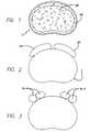
- FIG. 1 of the attached drawingsshows a cross-sectional top plan view of a vertebral body V in the lumbar spine to illustrate the dense bone of the apophyseal rim AR present proximate the perimeter of the vertebral body V about the endplate region and an inner mass of cancellous bone CB.
- the structure of the vertebral bodyhas been compared to a core of wet balsa wood encased in a laminate of white oak.
- the apophyseal rim ARis the best structural bone and is peripherally disposed in the endplate of the vertebral body.
- FIG. 2is a top plan view of a fourth level lumbar vertebral body V shown in relationship anteriorly with the aorta and vena cava (collectively referred to as the “great vessels” GV).
- FIG. 3is a top plan view of a first sacral level vertebral body V shown in relationship anteriorly with the iliac arteries and veins referred to by the designation “IA-V”. Because of the location of these fragile blood vessels along the anterior aspect of the lumbar vertebrae, no hardware should protrude from between the vertebral bodies and into the great vessels GV and iliac arteries and veins IA-V.
- Fusion implantspreferably have a structure designed to promote fusion of the adjacent vertebral bodies by allowing for the growth of bone through the implant from vertebral body to adjacent vertebral body.
- This type of implantis intended to remain indefinitely within the patient's spine unless made of a resorbable or bioresorbable material such as bone that can be biologically replaced in the body over time such that it need not be removed as it is replaced over time will no longer be there.
- Implantsmay be sized to have a width generally as great as the nucleus portion of the disc or as wide as the area between the limit lines LL as shown in FIG. 4 . There are at least two circumstances where the use of such a wide implant is not desirable.
- the use of a pair of implants each having a width less than one half the width of the disc space to be fusedis preferred.
- the first circumstanceis where the implants are for insertion into the lumbar spine from a posterior approach. Because of the presence of the dural sac within the spinal canal, the insertion of a full width implant in a neurologically intact patient could not be performed from a posterior approach.
- the second circumstanceis where the implants are for endoscopic, such as laproscopic, insertion regardless of the approach as it is highly desirable to minimize the ultimate size cross-sectionally of the path of insertion.
- the ability to achieve spinal fusionis inter alia directly related to the vascular surface area of contact over which the fusion can occur, the quality and the quantity of the fusion mass, and the stability of the construct.
- the overall size of interbody spinal fusion implantsis limited, however, by the shape of the implants relative to the natural anatomy of the human spine. For example, if such implants were to protrude from the spine they might cause injury to one or more of the proximate vital structures including the large blood vessels or neurological structures.
- FIG. 4shows a top plan view of the endplate region of a vertebral body V with the outline of a related art implant A and implant 100 of one embodiment of the present invention installed, one on each side of the centerline of the vertebral body V.
- the length and width of related art implant Ais limited by its configuration and the vascular structures anteriorly (in this example) adjacent to the implantation space.
- the presence of limiting corners LC on the implantprecludes the surgeon from utilizing an implant of this configuration having both the optimal width and length because the implant would markedly protrude from the spine.
- an interbody spinal fusion implanthaving opposed portions for placement toward adjacent vertebral bodies that is capable of fitting within the outer boundaries of the vertebral bodies between which the implant is to be inserted and to maximize the surface area of contact of the implant and vertebral bone.
- the implantshould achieve this purpose without interfering with the great vessels or neurological structures adjacent to the vertebrae into which the implant is to be implanted.
- an implantthat is adapted for placement more fully on the dense cortical bone proximate the perimeter of the vertebral bodies at the implant's leading end.
- the present inventionrelates to a spinal implant formed or manufactured prior to surgery and provided fully formed to the surgeon for use in interbody fusion formed of bone.
- the implantis of a width preferably sized to be used in pairs to generally replace all or a great portion of all of the width of the nucleus portion of the disc. To that end, the width of the implant is less than half of the width of the disc space.
- the implantgenerally has parallel side walls and is used where it is desirable to insert an implant of enhanced length without the leading lateral wall protruding from the spine.
- the interbody spinal implant of the present inventionis for placement between adjacent vertebral bodies of a human spine across the height of the disc space between those adjacent vertebral bodies.
- the implantpreferably does not extend beyond the outer dimensions of the two vertebral bodies adjacent that disc space and preferably maximizes the area of contact of the implant with the vertebral bone.
- the implanthas a leading end configured to conform to the anatomic contour of at least a portion of the anterior, posterior, or lateral aspects of the vertebral bodies depending on the intended direction of insertion of the implant, so as to not protrude beyond the curved contours thereof.
- the implanthas an asymmetrical leading end modified to allow for enhanced implant length without the corner of the leading end protruding out of the disc space.
- the phrase “asymmetrical leading end”is defined as the leading end of the implant lacking symmetry from side-to-side along the transverse axis of the implant when the leading end is viewed from a top elevation.
- the configuration of the leading end of the implant of the present inventionallows for the safe use of an implant of maximum length for the implantation space into which it is installed.
- Benefits derived from a longer length implantinclude, but are not limited to, providing a greater surface area for contacting the vertebral bodies and for carrying bone growth promoting materials at the implant surface, increasing the load bearing support area, increased stability, increased internal volume for holding fusion promoting material, and the ability to have a portion of the implant rest upon the apophyseal rim, the best structural bone of the vertebral endplate region.
- These fusion promoting and bone growth promoting materialsmay be bone, bone products, bone morphogenetic proteins, mineralizing proteins, genetic materials coding for the production of bone, or any other suitable material.
- the spinal implant of the present inventionmay also include a trailing end opposite the leading end that is configured to conform to the anatomic contour of the anterior, posterior, or lateral aspects of the vertebral bodies, depending on the direction of insertion, so as not to protrude beyond the curved contours thereof.
- the present inventioncan benefit interbody spinal fusion implants having spaced apart non-arcuate opposed surfaces adapted to contact and support opposed adjacent vertebral bodies as well as implants having spaced apart arcuate opposed surfaces adapted to penetrably engage opposed vertebral bodies.
- arcuaterefers to the curved configuration of the opposed upper and lower portions of the implant transverse to the longitudinal axis of the implant along at least a portion of the implant's length.
- an implant adapted for insertion from the posterior approach of the spine, and for achieving better, safe filling of the posterior to anterior depth of the disc space between two adjacent vertebral bodies, and for the possibility of having the leading end of the implant supported by the structurally superior more peripheral bone including the apophyseal rim and the bone adjacent to itincludes opposed portions adapted to be oriented toward the bone of the adjacent vertebral bodies, a leading end for inserting into the spine, and an opposite trailing end that may be adapted to cooperatively engage a driver.
- the implantmay receive a portion of the driver through the trailing end to cooperatively engage the implant from within and/or at the implant trailing end.
- the leading end of this embodiment of the implant of the present inventionis generally configured to conform to the natural anatomical curvature of the perimeter of the anterior aspect of the vertebral bodies, so that when the implant is fully inserted and properly seated within and across the disc space the implant contacts and supports a greater surface area of the vertebral bone in contact with the implant to provide all the previously identified advantages.
- the implant of the present inventionis configured to be able to be seated upon the more densely compacted bone about the periphery of the vertebral endplates for supporting the load through the implant when installed in or across the height of the intervertebral space.
- the present invention implantsmay have an interior facing medial side wall adapted for placement medially within the disc space with the side wall intact and substantially in the same plane and an exterior facing lateral side wall opposite to the medial side wall and adapted for placement laterally.
- the implants of the present inventionalso have a mid-longitudinal axis between the medial and lateral side walls wherein the mid-longitudinal axis at the leading end extends forward further than the lateral side wall of the leading end while the medial side wall is not equal in length to the lateral side wall, but is greater in length.
- an implant for insertion from the anterior approach of the spine and for achieving better filling of the anterior to posterior depth of the disc spacehas a leading end generally configured to better conform to the natural anatomical curvature of the perimeter of the posterior aspect of the vertebral bodies and does not protrude laterally.
- the implanthas a trailing end that is either asymmetric or symmetric from side-to-side along the transverse axis of the implant.
- the trailing endmay be adapted to conform to the anatomical contours of the anterior or posterior aspects of the vertebral bodies.
- an implant for insertion from the posterior or anterior approach of the spinehas a leading end that is generally configured to better conform to the natural anatomical curvature of at least one of the perimeter of the anterior and posterior aspects, respectively, of the vertebral bodies and a trailing end that is generally configured to conform to the natural anatomical curvature of the opposite one of the posterior and anterior aspects, respectively, of the vertebral bodies depending on the intended direction of insertion and that does not protrude laterally from the vertebral bodies.
- an implant in accordance with the present invention for insertion from a translateral approach to the spine and across the transverse width of the vertebral bodieshas a leading end that is generally configured to better conform to the natural anatomical curvature of the perimeter of at least one of the lateral aspects, respectively, of the vertebral bodies.
- the implantalso may have a trailing end that is generally configured to conform to the natural anatomical curvature of the opposite one of the lateral aspects, respectively, of the vertebral bodies depending on the intended direction of insertion.
- the implant of the present inventionis better able to sit upon the dense compacted bone about the perimeter of the vertebral bodies of the vertebral endplate region for supporting the load through the implant when installed in the intervertebral space.
- the spinal fusion implants of the present inventionhas at least one opening therethrough from the upper vertebral body contacting surface through to the lower vertebral body contacting surface to permit for the growth of bone in continuity from adjacent vertebral body to adjacent vertebral body through the implant for fusion across the disc space.
- the implantpreferably includes protrusions or surface roughenings for engaging the bone of the vertebral bodies adjacent to the implant.
- the material of the implantis bone that is either in a naturally occurring state, or a composite material made of bone particles.
- the implantcan be manufactured from a piece of bone obtained from a major long bone or other suitable source and can include bone dowels and diaphyseal bone rings, for example.
- the implantscan be manufactured from a composite of bone made up of cortical fibers, bone filaments, or bone particles, as examples, and at least a second substance preferably bioresorbable such as a plastic or ceramic suitable for the intended purpose.
- the composite materialcould be machineable, or moldable, into the desired shape.
- Boneoffers the advantages of an appropriate modulus of elasticity and strength for the prescribed use, the capacity to be bioactive, including being osteoconductive, osteoinductive, osteogenic, and to more generally provide a good substrate for the formation of new bone as fusion occurs. Further, the bone material being bioabsorable is replaced by the patient's own bone over time preventing stress shielding and leading to the eventual elimination of any foreign body from the implantation site.
- the implantsmay further include other osteogenic materials such as bone morphogenetic proteins, or other chemical compounds, or genetic material coding for the production of bone, the purpose of which is to induce or otherwise encourage the formation of bone or fusion.
- the implantsare of a composite material, they could comprise of a bioresorbable material including, but not limited to various ceramics or plastics. Suitable plastics may include those comprising lactides, galactides, glycolide, capronlactone, trimethylene carbonate, dioxanone, in various polymers and/or combinations.
- the implantsmay be adapted to receive fusion promoting substances within them such as cancellous bone, bone derived products, or others.
- implant of the present inventionas described herein are applicable to various embodiments of the present invention including implants having non-arcuate or arcuate upper and lower opposed portions adapted to be oriented toward the bone of the adjacent vertebral bodies.
- FIG. 1is a top plan view of a horizontal cross-section through a boney endplate region of a vertebral body.
- FIGS. 2-3are top plan views of the fourth lumbar and first sacral vertebral bodies, respectively, in relationship to the blood vessels located anteriorly thereto.
- FIG. 4is a top plan view of an endplate region of a vertebral body with a prior art implant on the left side of the center line and an implant in accordance with one embodiment of the present invention on the right side of the centerline inserted from the posterior aspect of the spine.
- FIG. 5is a side perspective view of the outline of an implant in accordance with one embodiment of the present invention.
- FIG. 6is a partial enlarged fragmentary view along line 6 - 6 of FIG. 5 .
- FIG. 7is a top plan view of a lumbar vertebral body in relationship to the blood vessels located proximate thereto and an implant in accordance with one embodiment of the present invention inserted from the posterior aspect of the vertebral body.
- FIG. 8is a top plan view of a lumbar vertebral body in relationship to the blood vessels located proximate thereto and an implant in accordance with one embodiment of the present invention inserted from the anterior aspect of the vertebral body.
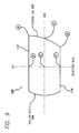
- FIG. 9is a top plan view of an implant in accordance with one embodiment of the present invention illustrating the mid-longitudinal axis and a plane bisecting the mid-longitudinal axis along the length of the implant.
- FIG. 10is a top plan view of a lumbar vertebral body in relationship to the blood vessels located proximate thereto and an implant having arcuate upper and lower opposed portions in accordance with an embodiment of the present invention inserted from the posterior aspect of the vertebral body.
- FIG. 11is a trailing end view of a spinal implant shown in FIG. 10 .
- FIG. 4shows an embodiment of the present invention comprising an interbody spinal implant generally referred by the numeral 100 , inserted in the direction of arrow P from the posterior aspect of a vertebral body V on one side of the centerline M in the lumbar spine.
- the implantcan be made of bone that is either in a naturally occurring state, or can be made of a composite material comprising bone particles.
- the implantcan be manufactured from a piece of bone obtained from a major long bone or other suitable source and can include bone dowels and diaphyseal bone rings, for example.
- the implantscan be manufactured from a composite of bone made up of cortical fibers, bone filaments, bone particles, as examples.
- the compositemay also include a material which may or may not be bioactive and/or bioresorbable such as a plastic, ceramic, or other. Once formed, the bone composite implant could be machineable, or moldable, into the desired shape.
- the implantsmay further include other osteogenic materials such as bone morphogenetic proteins, or other chemical compounds, or genetic material coding for the production of bone, the purpose of which is to induce or otherwise encourage the formation of bone or fusion.
- the implantscould comprise a bioresorbable material including, but not limited to cortical bone, plastics and composite plastics. Suitable plastics may include those comprising lactides, galactides, glycolide, capronlactone, trimethylene carbonate, dioxanone in various polymers and/or combinations.
- Implant 100has a leading end 102 for insertion into the disc space and an opposite trailing end 104 .
- leading end 102is configured to not extend beyond the outer dimensions of the two vertebral bodies adjacent the disc space proximate leading end 102 after implant 100 is installed, to maximize the area of contact of the implant with the vertebral bone.
- Leading end 102could be described as being generally configured to generally conform to at least a portion of the natural anatomical curvature of the aspect of the vertebral bodies adjacent the disc space proximate leading end 102 after implant 100 is installed. The general configuration of leading end 102 is further described in connection with FIG. 9 below.
- leading end 102 ais adapted to conform to at least a portion of the anterior aspect of the vertebral body V.
- leading end 102 bis adapted to conform to at least a portion of the posterior aspect of vertebral body V.
- Trailing end 104may be symmetrical or asymmetrical from side-to-side along the transverse axis of the implant and can conform to at least a portion of the natural curvature of the aspect of vertebral body V opposite to leading end 102 . Trailing end 104 may or may not be configured to conform to the aspect of vertebral body V proximate trailing end 104 after implant 100 is installed. Trailing end 104 need only have a configuration suitable for its intended use in the spine.
- implant 100has opposed portions 106 and 108 that are adapted to contact and support adjacent vertebral bodies when inserted across the intervertebral space.
- opposed portions 106 , 108have a non-arcuate configuration transverse to the longitudinal axis of implant 100 along at least a portion of the length of implant 100 .
- Opposed portions 106 , 108are spaced apart and connected by an interior side wall 112 and an exterior side wall 114 opposite interior side wall 112 .
- Interior side wall 112is the portion of implant 100 adapted to be placed toward another implant when implant 100 is inserted in pairs into the disc space between the adjacent vertebral bodies to be fused.
- Interior side wall 112is not the internal surface of a hollow interior of implant 100 .
- Exterior side wall 114is adapted to be placed into the disc space nearer to the perimeter of the vertebral bodies than interior side wall 112 .
- Side walls 112 , 114are preferably continuous from leading end to trailing end.
- Sidewalls 112 , 114may also include at least one opening for permitting for the growth of bone therethrough.
- each of the opposed portions 106 108have at least one opening 110 in communication with one another to permit for the growth of bone in continuity from adjacent vertebral body to adjacent vertebral body and through implant 100 .
- Opening 110is preferably a through-hole with a maximum cross-sectional dimension greater than 0.5 mm between interior side wall 112 and exterior side wall 114 passing completely through the implant and is preferably adapted to hold bone growth promoting material for permitting for the growth of bone from vertebral body to vertebral body through the implant.
- the perimeter of the through-holeis preferably continuous and uninterrupted.
- Implant 100may further be hollow or at least in part hollow. Implant 100 may also include surface roughenings on for example, at least a portion of opposed portions 106 , 108 for engaging the bone of the adjacent vertebral bodies.
- implant 100has a mid-longitudinal axis MLA along its length.
- Mid-longitudinal axis MLAis bisected by a plane BPP perpendicular to and bisecting the length of implant 100 along the mid-longitudinal axis MLA.
- Implant 100has a first distance as measured from point C at leading end 102 to bisecting perpendicular plane BPP at point E that is greater than a second distance as measured from bisecting perpendicular plane BPP at point F to the junction of leading end 102 and exterior side wall 114 at point B.
- Implant 100has a third distance as measured from point A at the junction of leading end 102 and interior side wall 112 to bisecting perpendicular plane BPP at point D that is greater than the second distance as measured from at point F to point B. While in the preferred embodiment as shown in FIG. 9, the third distance from points A to D is illustrated as being longer than the first distance from points C to E, the third distance can be equal to or less than the first distance. In a preferred embodiment, the first distance measured from points C to E is greater than the second distance measured from points B to F; the third distance measured from points A to D can be less than the first distance measured from points C to E; and the third distance measured from points A to D does not equal the second distance measured from points B to F.
- implant 100when implant 100 is inserted between two adjacent vertebral bodies, implant 100 is contained completely within the vertebral bodies so as not to protrude from the spine. Specifically, the most lateral aspect of the implanted implant at the leading end has been relieved, foreshortened, or contoured so as to allow the remainder of the implant to be safely enlarged so as to be larger overall than the prior implants without the leading end lateral wall protruding from the disc space. Although overall enlargement of the implant is a preferred feature of one embodiment of the present invention, it is not a requisite element of the invention.
- FIG. 10While a preferred embodiment of the present invention has been illustrated and described herein in the form of an implant having non-arcuate upper and lower portions along a portion of the length of the implant, another preferred embodiment of the present invention as best shown in FIG. 10 includes an implant having arcuate upper and lower portions along at least a portion of the length of the implant. All of the features described in association with the non-arcuate embodiments are equally applicable to the arcuate embodiments of the present invention.
- FIGS. 10-11show two interbody spinal implants generally referred to by the numeral 200 , inserted in the direction of arrow P from the posterior aspect of a vertebral body V, one on either side of the centerline M in the lumbar spine.
- Implant 200is non-threaded and is configured for linear insertion into the disc space in a direction along the mid-longitudinal axis of implant 200 .
- Implant 200has a leading end 202 for insertion into the disc space and an opposite trailing end 204 .
- leading end 202is configured to not extend beyond the outer dimensions of the two vertebral bodies adjacent the disc space proximate leading end 202 after implant 200 is installed, to maximize the area of contact of the implant with the vertebral bone.
- Leading end 202could be described as being generally configured to generally conform to at least a portion of the natural anatomical curvature of the aspect of the vertebral bodies adjacent the disc space proximate leading end 202 after implant 200 is installed. In a preferred embodiment, less than half of asymmetric leading end 202 is along a line perpendicular to the mid-longitudinal axis of the implant in a plane dividing the implant into an upper half and a lower half.
- more than half of the leading endcan be a contour that goes from the exterior side wall toward the mid-longitudinal axis of the implant in the plane dividing the implant into an upper half and a lower half.
- the leading endincludes a curve that extends from the exterior side wall beyond the mid-longitudinal axis of the implant.
- the more pronounced curve of the leading end of the implant of the present invention as compared to the chamfer of related art implantsadvantageously provides for closer placement of the implant's leading end to the perimeter of the vertebral body, without the limiting corner protruding therefrom, to more fully utilize the dense cortical bone in the perimeter of the vertebral bodies.
- the configuration of the implant of the present inventionprovides the use of an implant having a longer overall length as measured from leading end to trailing end for a better fill of the disc space.
- Implant 200has opposed portions 206 and 208 that are arcuate transverse to the longitudinal axis of implant 200 along at least a portion of the length of implant 200 and are adapted to contact and support adjacent vertebral bodies when inserted across the intervertebral space and into the vertebral bodies.
- Implant 200can further include protrusions or surface roughenings such as ratchetings 220 for enhancing stability. Surface roughenings may also include ridges, knurling and the like.
- the present inventionis not limited to use in the lumbar spine and is useful throughout the spine.
- use in the cervical spineby way of example, in addition to various blood vessels the esophagus and trachea also should be avoided.
- the implant of the present inventionpreferably includes non-arcuate opposed surface portions that are either generally parallel to one another along the length of the implant or in angular relationship to each other such that the opposed surfaces are closer to each other proximate one end of the implant than at the longitudinally opposite other.
- the spinal implant of the present inventionallows for a variable surface, or any other configuration and relationship of the opposed surfaces.
- Implant 100may be adapted to cooperatively engage a driver instrument for installation of the implant into the recipient site.
- trailing end 104may be configured to complementary engage an instrument for driving implant 100 .
- the teaching of having the implant leading end be arcuate or truncated along one side (the lateral leading end) or from side to side so as to eliminate the length limiting lateral leading corner LC or the side wall or lateral aspect junction to the implant leading endis of such benefit that minor differences do not detract from its utility.
- the range of describable curvaturesmay be varied proportionately with the size of the implants as well as their intended location within the spine and direction of insertion to be most appropriate and is easily determinable by those of ordinary skill in the art.
- the arc of radius of the curvature of the leading end of the implantshould be from 10-30 mm to be of greatest benefit, though it could be greater or less, and still be beneficial.
- the arc of radiusis preferably 8-20 mm.
Landscapes
- Chemical & Material Sciences (AREA)
- Engineering & Computer Science (AREA)
- Health & Medical Sciences (AREA)
- Oil, Petroleum & Natural Gas (AREA)
- Biomedical Technology (AREA)
- Organic Chemistry (AREA)
- General Chemical & Material Sciences (AREA)
- Chemical Kinetics & Catalysis (AREA)
- Neurology (AREA)
- Orthopedic Medicine & Surgery (AREA)
- Life Sciences & Earth Sciences (AREA)
- Cardiology (AREA)
- General Health & Medical Sciences (AREA)
- Public Health (AREA)
- Veterinary Medicine (AREA)
- Wood Science & Technology (AREA)
- Animal Behavior & Ethology (AREA)
- Vascular Medicine (AREA)
- Heart & Thoracic Surgery (AREA)
- Transplantation (AREA)
- Oral & Maxillofacial Surgery (AREA)
- Inorganic Chemistry (AREA)
- Prostheses (AREA)
Abstract
Description
1. Field of the Invention
The present invention relates generally to interbody spinal implants preferably adapted for placement in pairs side by side to either side of the midline with or without a space therebetween into a space created across the height of a disc space and between two adjacent vertebral bodies, after the removal of damaged spinal disc material, for the purpose of correcting spinal disease at that interspace. The spinal implants comprise of cortical bone either in a form such as a material that may naturally be available from a body; or as a composite material of cortical bone in particles or spindles, and the like in a resorbable plastic, ceramic, or other so long as it is structurally suitable for the intended purpose. The implants are adapted such that fusion occurs at least in part through the implants themselves.
2. Description of the Related Art
Surgical interbody spinal fusion generally refers to the methods for achieving a bridge of bone tissue in continuity between adjacent vertebral bodies and across the disc space to thereby substantially eliminate relative motion between the adjacent vertebral bodies. The term “disc space” refers to the space between adjacent vertebral bodies normally occupied by a spinal disc.
Spinal implants can have opposed upper and lower surfaces that are arcuate or non-arcuate transverse to the longitudinal axis of the implant along at least a portion of the length of the implant. Implants having arcuate opposed portions are adapted to be implanted across and beyond the height of the restored disc space, generally into a bore formed across the height of a disc space. Some of the advantages offered by implants with arcuate opposed portions include: 1) the installation of the implant into vascular bone made possible by the creation of a bore into the bone of the adjacent vertebral bodies; 2) the implant's geometric shape is easy to manufacturer 3) the implant can include external threads to facilitate insertion into the implantation space; and 4) the implant provides more surface area to contact the adjacent vertebral bodies, than would a flat surface. Some disadvantages associated with implants having arcuate opposed portions include: 1) the creation of a bore into the adjacent vertebral bodies to form the implantation space results in a loss of the best structural bone of the vertebral endplate; 2) the implant needs to have a larger cross section to fill the prepared implantation site which may be more difficult to install, especially from a posterior approach; and 3) the width of the implant is generally related to the height of the implant, so if the implant is for example a cylinder, then the width of the implant may be a limiting factor as to the height of the implant and therefore its possible usefulness.
Implants having non-arcuate upper and lower opposed portions may be impacted into a space resembling the restored disc space and need only be placed against a “decorticated endplate”. A decorticated endplate is prepared by a surgeon to provide access to the underlying vascular bone. Some of the advantages provided by implants having non-arcuate opposed portions include: 1) preserving the best bone in the endplate region; 2) the height of the implant is independent of its width; 3) the implant can be of a geometric shape and the opposed upper and lower surfaces can be flat; 4) the implant can be installed as modular unit; and 5) the implant can provide a broad surface contact. Some of the disadvantages provided by implants having non-arcuate opposed portions include: 1) the implants cannot be threaded in and must be impacted into the installation space; and 2) the recipient site may be more difficult to prepare.
Human vertebral bodies have a hard outer shell of compacted dense cancellous bone (sometimes referred to as the cortex) and a relatively softer, inner mass of cancellous bone. Just below the cortex adjacent the disc is a region of bone referred to herein as the “subchondral zone”. The outer shell of compact bone (the boney endplate) adjacent to the spinal disc and the underlying subchondral zone are together herein referred to as the boney “end plate region” and, for the purposes of this application, is hereby so defined. A circumferential ring of dense bone extends around the perimeter of the endplate region and is the mature boney successor of the “apophyseal growth ring”. This circumferential ring is formed of very dense bone and for the purposes of this application will be referred to as the “apophyseal rim”. For purposes of this application, the “apophyseal rim area” includes the apophyseal rim and additionally includes the dense bone immediately adjacent thereto. The spinal disc that normally resides between the adjacent vertebral bodies maintains the spacing between those vertebral bodies and, in a healthy spine, allows for the normal relative motion between the vertebral bodies.
FIG. 1 of the attached drawings shows a cross-sectional top plan view of a vertebral body V in the lumbar spine to illustrate the dense bone of the apophyseal rim AR present proximate the perimeter of the vertebral body V about the endplate region and an inner mass of cancellous bone CB. The structure of the vertebral body has been compared to a core of wet balsa wood encased in a laminate of white oak. The apophyseal rim AR is the best structural bone and is peripherally disposed in the endplate of the vertebral body.
FIG. 2 is a top plan view of a fourth level lumbar vertebral body V shown in relationship anteriorly with the aorta and vena cava (collectively referred to as the “great vessels” GV). FIG. 3 is a top plan view of a first sacral level vertebral body V shown in relationship anteriorly with the iliac arteries and veins referred to by the designation “IA-V”. Because of the location of these fragile blood vessels along the anterior aspect of the lumbar vertebrae, no hardware should protrude from between the vertebral bodies and into the great vessels GV and iliac arteries and veins IA-V.
Fusion implants preferably have a structure designed to promote fusion of the adjacent vertebral bodies by allowing for the growth of bone through the implant from vertebral body to adjacent vertebral body. This type of implant is intended to remain indefinitely within the patient's spine unless made of a resorbable or bioresorbable material such as bone that can be biologically replaced in the body over time such that it need not be removed as it is replaced over time will no longer be there. Implants may be sized to have a width generally as great as the nucleus portion of the disc or as wide as the area between the limit lines LL as shown in FIG.4. There are at least two circumstances where the use of such a wide implant is not desirable. Under these circumstances, the use of a pair of implants each having a width less than one half the width of the disc space to be fused is preferred. The first circumstance is where the implants are for insertion into the lumbar spine from a posterior approach. Because of the presence of the dural sac within the spinal canal, the insertion of a full width implant in a neurologically intact patient could not be performed from a posterior approach. The second circumstance is where the implants are for endoscopic, such as laproscopic, insertion regardless of the approach as it is highly desirable to minimize the ultimate size cross-sectionally of the path of insertion.
The ability to achieve spinal fusion is inter alia directly related to the vascular surface area of contact over which the fusion can occur, the quality and the quantity of the fusion mass, and the stability of the construct. The overall size of interbody spinal fusion implants is limited, however, by the shape of the implants relative to the natural anatomy of the human spine. For example, if such implants were to protrude from the spine they might cause injury to one or more of the proximate vital structures including the large blood vessels or neurological structures.
FIG. 4 shows a top plan view of the endplate region of a vertebral body V with the outline of a related art implant A andimplant 100 of one embodiment of the present invention installed, one on each side of the centerline of the vertebral body V. The length and width of related art implant A is limited by its configuration and the vascular structures anteriorly (in this example) adjacent to the implantation space. The presence of limiting corners LC on the implant precludes the surgeon from utilizing an implant of this configuration having both the optimal width and length because the implant would markedly protrude from the spine.
Related art implants also fail to maximally sit over the best structural bone, which is located peripherally in the apophyseal rim of the vertebral body and is formed of the cortex and dense subchondral bone. The configurations of previous implants do not allow for maximizing both the vital surface area over which fusion could occur and the area available to bear the considerable loads present across the spine. Previous implant configurations do not allow for the full utilization of the apophyseal rim bone and the bone adjacent to it, located proximate the perimeter of the vertebral body to support the implants at their leading ends and to maximize the overall support area and area of contact for the implants. The full utilization of this dense peripheral bone would be ideal.
Therefore, there is a need for an interbody spinal fusion implant having opposed portions for placement toward adjacent vertebral bodies that is capable of fitting within the outer boundaries of the vertebral bodies between which the implant is to be inserted and to maximize the surface area of contact of the implant and vertebral bone. The implant should achieve this purpose without interfering with the great vessels or neurological structures adjacent to the vertebrae into which the implant is to be implanted. There exists a further need for an implant that is adapted for placement more fully on the dense cortical bone proximate the perimeter of the vertebral bodies at the implant's leading end.
The present invention relates to a spinal implant formed or manufactured prior to surgery and provided fully formed to the surgeon for use in interbody fusion formed of bone. The implant is of a width preferably sized to be used in pairs to generally replace all or a great portion of all of the width of the nucleus portion of the disc. To that end, the width of the implant is less than half of the width of the disc space. Preferably, the implant generally has parallel side walls and is used where it is desirable to insert an implant of enhanced length without the leading lateral wall protruding from the spine.
The interbody spinal implant of the present invention is for placement between adjacent vertebral bodies of a human spine across the height of the disc space between those adjacent vertebral bodies. The implant preferably does not extend beyond the outer dimensions of the two vertebral bodies adjacent that disc space and preferably maximizes the area of contact of the implant with the vertebral bone. In a preferred embodiment, the implant has a leading end configured to conform to the anatomic contour of at least a portion of the anterior, posterior, or lateral aspects of the vertebral bodies depending on the intended direction of insertion of the implant, so as to not protrude beyond the curved contours thereof. The implant has an asymmetrical leading end modified to allow for enhanced implant length without the corner of the leading end protruding out of the disc space. As used herein, the phrase “asymmetrical leading end” is defined as the leading end of the implant lacking symmetry from side-to-side along the transverse axis of the implant when the leading end is viewed from a top elevation.
The configuration of the leading end of the implant of the present invention allows for the safe use of an implant of maximum length for the implantation space into which it is installed. Benefits derived from a longer length implant include, but are not limited to, providing a greater surface area for contacting the vertebral bodies and for carrying bone growth promoting materials at the implant surface, increasing the load bearing support area, increased stability, increased internal volume for holding fusion promoting material, and the ability to have a portion of the implant rest upon the apophyseal rim, the best structural bone of the vertebral endplate region. These fusion promoting and bone growth promoting materials may be bone, bone products, bone morphogenetic proteins, mineralizing proteins, genetic materials coding for the production of bone, or any other suitable material.
The spinal implant of the present invention may also include a trailing end opposite the leading end that is configured to conform to the anatomic contour of the anterior, posterior, or lateral aspects of the vertebral bodies, depending on the direction of insertion, so as not to protrude beyond the curved contours thereof. The present invention can benefit interbody spinal fusion implants having spaced apart non-arcuate opposed surfaces adapted to contact and support opposed adjacent vertebral bodies as well as implants having spaced apart arcuate opposed surfaces adapted to penetrably engage opposed vertebral bodies. As used herein, the term “arcuate” refers to the curved configuration of the opposed upper and lower portions of the implant transverse to the longitudinal axis of the implant along at least a portion of the implant's length.
In one embodiment of the present invention, an implant adapted for insertion from the posterior approach of the spine, and for achieving better, safe filling of the posterior to anterior depth of the disc space between two adjacent vertebral bodies, and for the possibility of having the leading end of the implant supported by the structurally superior more peripheral bone including the apophyseal rim and the bone adjacent to it, includes opposed portions adapted to be oriented toward the bone of the adjacent vertebral bodies, a leading end for inserting into the spine, and an opposite trailing end that may be adapted to cooperatively engage a driver. In the alternative, the implant may receive a portion of the driver through the trailing end to cooperatively engage the implant from within and/or at the implant trailing end. The leading end of this embodiment of the implant of the present invention is generally configured to conform to the natural anatomical curvature of the perimeter of the anterior aspect of the vertebral bodies, so that when the implant is fully inserted and properly seated within and across the disc space the implant contacts and supports a greater surface area of the vertebral bone in contact with the implant to provide all the previously identified advantages. Moreover, at the election of the surgeon, the implant of the present invention is configured to be able to be seated upon the more densely compacted bone about the periphery of the vertebral endplates for supporting the load through the implant when installed in or across the height of the intervertebral space.
Related art bone ring implants where the implant is a circle, oval, or oblong have trailing ends that are either modified to be squared-off, or unmodified so as to remain a portion of a circle, an oval, or an oblong and have a medial side wall that is incomplete due to a portion of the medullary canal interrupting the side wall. The present invention implants may have an interior facing medial side wall adapted for placement medially within the disc space with the side wall intact and substantially in the same plane and an exterior facing lateral side wall opposite to the medial side wall and adapted for placement laterally. The implants of the present invention also have a mid-longitudinal axis between the medial and lateral side walls wherein the mid-longitudinal axis at the leading end extends forward further than the lateral side wall of the leading end while the medial side wall is not equal in length to the lateral side wall, but is greater in length.
In another embodiment of the present invention, an implant for insertion from the anterior approach of the spine and for achieving better filling of the anterior to posterior depth of the disc space has a leading end generally configured to better conform to the natural anatomical curvature of the perimeter of the posterior aspect of the vertebral bodies and does not protrude laterally.
In yet another embodiment of the present invention, the implant has a trailing end that is either asymmetric or symmetric from side-to-side along the transverse axis of the implant. The trailing end may be adapted to conform to the anatomical contours of the anterior or posterior aspects of the vertebral bodies. For example, an implant for insertion from the posterior or anterior approach of the spine has a leading end that is generally configured to better conform to the natural anatomical curvature of at least one of the perimeter of the anterior and posterior aspects, respectively, of the vertebral bodies and a trailing end that is generally configured to conform to the natural anatomical curvature of the opposite one of the posterior and anterior aspects, respectively, of the vertebral bodies depending on the intended direction of insertion and that does not protrude laterally from the vertebral bodies. When the implant is fully seated and properly inserted within and across the disc space, the surface area of the vertebral bone in contact with the implant is more fully utilized.
As another example, an implant in accordance with the present invention for insertion from a translateral approach to the spine and across the transverse width of the vertebral bodies has a leading end that is generally configured to better conform to the natural anatomical curvature of the perimeter of at least one of the lateral aspects, respectively, of the vertebral bodies. The implant also may have a trailing end that is generally configured to conform to the natural anatomical curvature of the opposite one of the lateral aspects, respectively, of the vertebral bodies depending on the intended direction of insertion. Implants for insertion from a translateral approach and methods for inserting implants from a translateral approach are disclosed in Applicant's U.S. Pat. Nos. 5,860,973 and 5,772,661, respectively, incorporated by reference herein.
The implant of the present invention is better able to sit upon the dense compacted bone about the perimeter of the vertebral bodies of the vertebral endplate region for supporting the load through the implant when installed in the intervertebral space. The spinal fusion implants of the present invention has at least one opening therethrough from the upper vertebral body contacting surface through to the lower vertebral body contacting surface to permit for the growth of bone in continuity from adjacent vertebral body to adjacent vertebral body through the implant for fusion across the disc space.
For any of the embodiments of the present invention described herein, the implant preferably includes protrusions or surface roughenings for engaging the bone of the vertebral bodies adjacent to the implant. In a preferred embodiment, the material of the implant is bone that is either in a naturally occurring state, or a composite material made of bone particles. In a naturally occurring state, the implant can be manufactured from a piece of bone obtained from a major long bone or other suitable source and can include bone dowels and diaphyseal bone rings, for example. Alternatively, the implants can be manufactured from a composite of bone made up of cortical fibers, bone filaments, or bone particles, as examples, and at least a second substance preferably bioresorbable such as a plastic or ceramic suitable for the intended purpose. The composite material could be machineable, or moldable, into the desired shape.
Bone offers the advantages of an appropriate modulus of elasticity and strength for the prescribed use, the capacity to be bioactive, including being osteoconductive, osteoinductive, osteogenic, and to more generally provide a good substrate for the formation of new bone as fusion occurs. Further, the bone material being bioabsorable is replaced by the patient's own bone over time preventing stress shielding and leading to the eventual elimination of any foreign body from the implantation site.
In addition to bone, the implants may further include other osteogenic materials such as bone morphogenetic proteins, or other chemical compounds, or genetic material coding for the production of bone, the purpose of which is to induce or otherwise encourage the formation of bone or fusion. In addition to bone, where the implants are of a composite material, they could comprise of a bioresorbable material including, but not limited to various ceramics or plastics. Suitable plastics may include those comprising lactides, galactides, glycolide, capronlactone, trimethylene carbonate, dioxanone, in various polymers and/or combinations.
Materials other than bone for use as the base material used to form the implant are specifically excluded from the definition of implant materials for the purpose of this application. The implants may be adapted to receive fusion promoting substances within them such as cancellous bone, bone derived products, or others.
It is appreciated that the features of the implant of the present invention as described herein are applicable to various embodiments of the present invention including implants having non-arcuate or arcuate upper and lower opposed portions adapted to be oriented toward the bone of the adjacent vertebral bodies.
FIG. 1 is a top plan view of a horizontal cross-section through a boney endplate region of a vertebral body.
FIGS. 2-3 are top plan views of the fourth lumbar and first sacral vertebral bodies, respectively, in relationship to the blood vessels located anteriorly thereto.
FIG. 4 is a top plan view of an endplate region of a vertebral body with a prior art implant on the left side of the center line and an implant in accordance with one embodiment of the present invention on the right side of the centerline inserted from the posterior aspect of the spine.
FIG. 5 is a side perspective view of the outline of an implant in accordance with one embodiment of the present invention.
FIG. 6 is a partial enlarged fragmentary view along line6-6 of FIG.5.
FIG. 7 is a top plan view of a lumbar vertebral body in relationship to the blood vessels located proximate thereto and an implant in accordance with one embodiment of the present invention inserted from the posterior aspect of the vertebral body.
FIG. 8 is a top plan view of a lumbar vertebral body in relationship to the blood vessels located proximate thereto and an implant in accordance with one embodiment of the present invention inserted from the anterior aspect of the vertebral body.
FIG. 9 is a top plan view of an implant in accordance with one embodiment of the present invention illustrating the mid-longitudinal axis and a plane bisecting the mid-longitudinal axis along the length of the implant.
FIG. 10 is a top plan view of a lumbar vertebral body in relationship to the blood vessels located proximate thereto and an implant having arcuate upper and lower opposed portions in accordance with an embodiment of the present invention inserted from the posterior aspect of the vertebral body.
FIG. 11 is a trailing end view of a spinal implant shown in FIG.10.
FIG. 4 shows an embodiment of the present invention comprising an interbody spinal implant generally referred by the numeral100, inserted in the direction of arrow P from the posterior aspect of a vertebral body V on one side of the centerline M in the lumbar spine. In a preferred embodiment of the present invention, the implant can be made of bone that is either in a naturally occurring state, or can be made of a composite material comprising bone particles. In a naturally occurring state, the implant can be manufactured from a piece of bone obtained from a major long bone or other suitable source and can include bone dowels and diaphyseal bone rings, for example. Alternatively, the implants can be manufactured from a composite of bone made up of cortical fibers, bone filaments, bone particles, as examples. In addition to bone, the composite may also include a material which may or may not be bioactive and/or bioresorbable such as a plastic, ceramic, or other. Once formed, the bone composite implant could be machineable, or moldable, into the desired shape.
In addition to bone, the implants may further include other osteogenic materials such as bone morphogenetic proteins, or other chemical compounds, or genetic material coding for the production of bone, the purpose of which is to induce or otherwise encourage the formation of bone or fusion. In addition to bone, the implants could comprise a bioresorbable material including, but not limited to cortical bone, plastics and composite plastics. Suitable plastics may include those comprising lactides, galactides, glycolide, capronlactone, trimethylene carbonate, dioxanone in various polymers and/or combinations.
As shown in FIGS. 7 and 8, depending on the direction of insertion, for example, whenimplant 100 is installed in the direction of arrow P from the posterior aspect of the vertebral body V, leadingend 102ais adapted to conform to at least a portion of the anterior aspect of the vertebral body V. Whenimplant 100 is installed in the direction of arrow A from the anterior aspect of vertebral body V, leadingend 102bis adapted to conform to at least a portion of the posterior aspect of vertebral bodyV. Trailing end 104 may be symmetrical or asymmetrical from side-to-side along the transverse axis of the implant and can conform to at least a portion of the natural curvature of the aspect of vertebral body V opposite to leadingend 102. Trailingend 104 may or may not be configured to conform to the aspect of vertebral body V proximate trailingend 104 afterimplant 100 is installed. Trailingend 104 need only have a configuration suitable for its intended use in the spine.
As shown in FIGS. 5 and 6,implant 100 has opposedportions portions implant 100 along at least a portion of the length ofimplant 100.Opposed portions interior side wall 112 and anexterior side wall 114 oppositeinterior side wall 112.Interior side wall 112 is the portion ofimplant 100 adapted to be placed toward another implant whenimplant 100 is inserted in pairs into the disc space between the adjacent vertebral bodies to be fused.Interior side wall 112 is not the internal surface of a hollow interior ofimplant 100.Exterior side wall 114 is adapted to be placed into the disc space nearer to the perimeter of the vertebral bodies thaninterior side wall 112.Side walls Sidewalls
Preferably, each of theopposed portions 106108 have at least oneopening 110 in communication with one another to permit for the growth of bone in continuity from adjacent vertebral body to adjacent vertebral body and throughimplant 100.Opening 110 is preferably a through-hole with a maximum cross-sectional dimension greater than 0.5 mm betweeninterior side wall 112 andexterior side wall 114 passing completely through the implant and is preferably adapted to hold bone growth promoting material for permitting for the growth of bone from vertebral body to vertebral body through the implant. The perimeter of the through-hole is preferably continuous and uninterrupted.Implant 100 may further be hollow or at least in part hollow.Implant 100 may also include surface roughenings on for example, at least a portion ofopposed portions
As illustrated in FIG. 9,implant 100 has a mid-longitudinal axis MLA along its length. Mid-longitudinal axis MLA is bisected by a plane BPP perpendicular to and bisecting the length ofimplant 100 along the mid-longitudinal axis MLA.Implant 100 has a first distance as measured from point C at leadingend 102 to bisecting perpendicular plane BPP at point E that is greater than a second distance as measured from bisecting perpendicular plane BPP at point F to the junction of leadingend 102 andexterior side wall 114 atpoint B. Implant 100 has a third distance as measured from point A at the junction of leadingend 102 andinterior side wall 112 to bisecting perpendicular plane BPP at point D that is greater than the second distance as measured from at point F to point B. While in the preferred embodiment as shown in FIG. 9, the third distance from points A to D is illustrated as being longer than the first distance from points C to E, the third distance can be equal to or less than the first distance. In a preferred embodiment, the first distance measured from points C to E is greater than the second distance measured from points B to F; the third distance measured from points A to D can be less than the first distance measured from points C to E; and the third distance measured from points A to D does not equal the second distance measured from points B to F.
In a preferred embodiment of the present invention, whenimplant 100 is inserted between two adjacent vertebral bodies,implant 100 is contained completely within the vertebral bodies so as not to protrude from the spine. Specifically, the most lateral aspect of the implanted implant at the leading end has been relieved, foreshortened, or contoured so as to allow the remainder of the implant to be safely enlarged so as to be larger overall than the prior implants without the leading end lateral wall protruding from the disc space. Although overall enlargement of the implant is a preferred feature of one embodiment of the present invention, it is not a requisite element of the invention.
While a preferred embodiment of the present invention has been illustrated and described herein in the form of an implant having non-arcuate upper and lower portions along a portion of the length of the implant, another preferred embodiment of the present invention as best shown in FIG. 10 includes an implant having arcuate upper and lower portions along at least a portion of the length of the implant. All of the features described in association with the non-arcuate embodiments are equally applicable to the arcuate embodiments of the present invention.
FIGS. 10-11 show two interbody spinal implants generally referred to by the numeral200, inserted in the direction of arrow P from the posterior aspect of a vertebral body V, one on either side of the centerline M in the lumbar spine.Implant 200 is non-threaded and is configured for linear insertion into the disc space in a direction along the mid-longitudinal axis ofimplant 200.Implant 200 has a leading end202 for insertion into the disc space and an opposite trailing end204. In a preferred embodiment, leading end202 is configured to not extend beyond the outer dimensions of the two vertebral bodies adjacent the disc space proximate leading end202 afterimplant 200 is installed, to maximize the area of contact of the implant with the vertebral bone. Leading end202 could be described as being generally configured to generally conform to at least a portion of the natural anatomical curvature of the aspect of the vertebral bodies adjacent the disc space proximate leading end202 afterimplant 200 is installed. In a preferred embodiment, less than half of asymmetric leading end202 is along a line perpendicular to the mid-longitudinal axis of the implant in a plane dividing the implant into an upper half and a lower half.
In a further preferred embodiment of either arcuate or non-arcuate implants, more than half of the leading end can be a contour that goes from the exterior side wall toward the mid-longitudinal axis of the implant in the plane dividing the implant into an upper half and a lower half. In another preferred embodiment of either arcuate or non-arcuate implants, the leading end includes a curve that extends from the exterior side wall beyond the mid-longitudinal axis of the implant. The more pronounced curve of the leading end of the implant of the present invention as compared to the chamfer of related art implants advantageously provides for closer placement of the implant's leading end to the perimeter of the vertebral body, without the limiting corner protruding therefrom, to more fully utilize the dense cortical bone in the perimeter of the vertebral bodies. The configuration of the implant of the present invention provides the use of an implant having a longer overall length as measured from leading end to trailing end for a better fill of the disc space.
The present invention is not limited to use in the lumbar spine and is useful throughout the spine. In regard to use in the cervical spine, by way of example, in addition to various blood vessels the esophagus and trachea also should be avoided.
Further, the implant of the present invention preferably includes non-arcuate opposed surface portions that are either generally parallel to one another along the length of the implant or in angular relationship to each other such that the opposed surfaces are closer to each other proximate one end of the implant than at the longitudinally opposite other. The spinal implant of the present invention allows for a variable surface, or any other configuration and relationship of the opposed surfaces.
While the exact contour and/or curvature of a particular vertebral body may not be known, the teaching of having the implant leading end be arcuate or truncated along one side (the lateral leading end) or from side to side so as to eliminate the length limiting lateral leading corner LC or the side wall or lateral aspect junction to the implant leading end is of such benefit that minor differences do not detract from its utility. Further, the range of describable curvatures may be varied proportionately with the size of the implants as well as their intended location within the spine and direction of insertion to be most appropriate and is easily determinable by those of ordinary skill in the art.
Generally for use in the lumbar spine, and where the leading end is a portion of a circle, then the arc of radius of the curvature of the leading end of the implant should be from 10-30 mm to be of greatest benefit, though it could be greater or less, and still be beneficial. The same is true for the cervical spine where the arc of radius is preferably 8-20 mm. While particular preferred embodiments of the present invention have been shown and described, it will be obvious to those skilled in the art that changes and modifications may be made without departing from this invention in its broader aspects.
While specific innovative features were presented in reference to specific examples, they are just examples, and it should be understood that various combinations of these innovative features beyond those specifically shown are taught such that they may now be easily alternatively combined and are hereby anticipated and claimed.
Claims (89)
1. An interbody spinal implant for insertion at least in part across a disc space between adjacent vertebral bodies of a human spine, the vertebral bodies having an anterior aspect and a posterior aspect, said implant comprising:
a leading end for insertion first into the disc space, a trailing end opposite said leading end, and therebetween a length along a mid-longitudinal axis of said implant, said leading end being asymmetrical;
opposed portions between said leading and trailing ends adapted to be placed within the disc space to contact and support the adjacent vertebral bodies, said opposed portions being non-arcuate along at least a portion of the length of said implant, said implant being formed of bone;
an interior facing side wall, an exterior facing side wall opposite said interior side wall, and a width therebetween, said width of said implant being less than approximately one-half of the maximum width of the adjacent vertebral bodies into which said implant is adapted to be inserted, said interior and exterior side walls connecting said opposed portions and said leading and trailing ends, said interior side wall adapted to be oriented toward another implant when inserted within the disc space;
at least one through-hole having a maximum cross-sectional dimension greater than 0.5 mm between said interior facing and said exterior facing side walls passing completely through said implant from opposed portion to opposed portion and adapted to hold bone growth promoting material for permitting for the growth of bone from vertebral body to vertebral body through said implant;
a first distance as measured from said leading end to a plane perpendicular to and bisecting the length along the mid-longitudinal axis of said implant that is greater than a second distance as measured from said perpendicular plane to the junction of said leading end and said exterior side wall; and
a third distance as measured from the junction of said leading end and said interior side wall to a plane perpendicular to and bisecting the length along the mid-longitudinal axis of said implant that is greater than said second distance.
2. The implant ofclaim 1 , wherein said first distance is greater than said third distance.
3. The implant ofclaim 1 , wherein said first distance is less than said third distance.
4. The implant ofclaim 1 , wherein said first distance and said third distance are approximately equal.
5. The implant ofclaim 1 , wherein said third distance is substantially greater than said first distance.
6. The implant ofclaim 1 , wherein said leading end is at least in part non-linear.
7. The implant ofclaim 1 , wherein more than half of said leading end is a contour that goes from the exterior side wall toward the mid-longitudinal axis of said implant in a plane dividing said implant into an upper half and a lower half.
8. The implant ofclaim 1 , wherein said leading end includes a curve that extends from said exterior side wall beyond the mid-longitudinal axis of said implant.
9. The implant ofclaim 1 , wherein less than half of said leading end is along a line perpendicular to the mid-longitudinal axis of said implant in a plane dividing said implant into an upper half and a lower half.
10. The implant ofclaim 1 , wherein at least a portion of said leading end is tapered for facilitating insertion of the implant between the two adjacent vertebral bodies.
11. The spinal implant ofclaim 1 , wherein said implant is adapted for insertion from the posterior aspect of the vertebral bodies and said leading end is configured to conform to the anatomic contour of at least a portion of the anterior aspect of the vertebral bodies.
12. The implant ofclaim 1 , wherein said implant is adapted for insertion from the anterior aspect of the vertebral bodies and said leading end is configured to conform to the anatomic contour of at least a portion of the posterior aspect of the vertebral bodies.
13. The implant ofclaim 1 , wherein said implant is adapted for insertion from a first lateral aspect of the vertebral bodies and said leading end is configured to conform to the anatomic contour of at least a portion of a second lateral aspect of the vertebral bodies opposite the first lateral aspect.
14. The implant ofclaim 1 , further comprising at least one protrusion extending from at least one of said opposed portions for engaging at least one of the adjacent vertebral bodies to maintain said implant within the disc space.
15. The implant ofclaim 14 , wherein said protrusion comprises a ridge.
16. The implant ofclaim 1 , further comprising a plurality of surface roughenings for engaging the adjacent vertebral bodies and for maintaining said implant in place, said surface roughenings being present on at least a portion of said opposed portions.
17. The implant ofclaim 1 , wherein said opposed portions have a porous surface.
18. The implant ofclaim 1 , wherein said opposed portions have a bone in growth surface.
19. The implant ofclaim 1 , wherein said implant material is selected from the group including cortical fibers, bone filaments, and bone particles.
20. The implant ofclaim 1 , in combination with a fusion promoting material other than bone.
21. The implant ofclaim 1 , wherein said implant comprises a bone in growth material other than bone.
22. The implant ofclaim 1 , further comprising a material, other than the bone from which said implant is formed, that intrinsically participates in the growth of bone from one of the adjacent vertebral bodies to the other of the adjacent vertebral bodies.
23. The implant ofclaim 1 , wherein said implant is treated with a fusion promoting substance.
24. The implant ofclaim 23 , wherein said fusion promoting substance is bone morphogenetic protein.
25. The implant ofclaim 1 , wherein at least a portion of said implant is bioresorbable.
26. The implant ofclaim 1 , further in combination with bone morphogenetic protein.
27. The implant ofclaim 1 , further in combination with an osteogenic material.
28. The implant ofclaim 27 , wherein said osteogenic material is a material other than bone.
29. The implant ofclaim 27 , wherein said material is genetic material coding for the production of bone.
30. The implant ofclaim 27 , wherein said material is bone morphogenetic protein.
31. The implant ofclaim 1 , further in combination with genetic material coding for production of bone.
32. The implant ofclaim 1 , further comprising a plurality of openings and passages for retaining fusion promoting substance.
33. The implant ofclaim 1 , wherein said implant has a maximum length less than and approximating the posterior to anterior depth of the vertebral body.
34. The implant ofclaim 1 , wherein said trailing end is adapted to conform from side to side to at least a portion of the peripheral contour of at least one of the anterior and posterior aspects of the vertebral bodies adjacent a disc space into which said implant is inserted.
35. The implant ofclaim 1 , wherein at least a portion of said opposed portions are in a diverging relationship to each other from trailing end to leading end for allowing angulation of the adjacent vertebral bodies relative to each other.
36. The implant ofclaim 1 , wherein at least a portion of said opposed portions re generally in a converging relationship to each other from trailing end to leading end or allowing angulation of the adjacent vertebral bodies relative to each other.
37. An interbody spinal implant for linear insertion at least in part across a disc space between adjacent vertebral bodies of a human spine, the vertebral bodies having an anterior aspect and a posterior aspect, said implant comprising:
a leading end for insertion first into the disc space, a trailing end opposite said leading end, and therebetween a length along a mid-longitudinal axis of said implant, said implant being non-threaded and adapted for linear insertion in a direction along the mid-longitudinal axis of said implant, said leading end being asymmetrical, less than half of said asymmetric leading end being along a line perpendicular to the mid-longitudinal axis of said implant in a plane dividing said implant into an upper half and a lower half;
opposed portions between said leading and trailing ends adapted to be placed within the disc space to contact and support the adjacent vertebral bodies, said opposed portions being arcuate along at least a portion of the length of said implant, said implant being formed of bone;
an interior facing side wall, an exterior facing side wall opposite said interior side wall, and a width therebetween, said width of said implant being less than approximately one-half of the maximum width of the adjacent vertebral bodies into which said implant is adapted to be inserted, said interior and exterior side walls connecting said opposed portions and said leading and trailing ends, said interior side wall adapted to be oriented toward another implant when inserted within the disc space;
a first distance as measured from said leading end to a plane perpendicular to and bisecting the length along the mid-longitudinal axis of said implant that is greater than a second distance as measured from said perpendicular plane to the junction of said leading end and said exterior side wall; and
a third distance as measured from the junction of said leading end and said interior side wall to a plane perpendicular to and bisecting the length along the midlongitudinal axis of said implant that is greater than said second distance.
38. The implant ofclaim 37 , wherein said first distance is greater than said third distance.
39. The implant ofclaim 37 , wherein said first distance is less than said third distance.
40. The implant ofclaim 37 , wherein said first distance and said third distance are approximately equal.
41. The implant ofclaim 37 , wherein said third distance is substantially greater than said first distance.
42. The implant ofclaim 37 , wherein said leading end is at least in part nonlinear.
43. The implant ofclaim 37 , wherein more than half of said leading end is a contour that goes from the exterior side wall toward the mid-longitudinal axis of said implant in a plane dividing said implant into an upper half and a lower half.
44. The implant ofclaim 37 , wherein said leading end includes a curve that extends from said exterior side wall beyond the mid-longitudinal axis of said implant.
45. The implant ofclaim 37 , wherein at least a portion of said leading end is tapered for facilitating insertion of the implant between the two adjacent vertebral bodies.
46. The implant ofclaim 37 , wherein said implant is adapted for insertion from the posterior aspect of the vertebral bodies and said leading end is configured to conform to the anatomic contour of at least a portion of the anterior aspect of the vertebral bodies.
47. The spinal implant ofclaim 37 , wherein said implant is adapted for insertion from the anterior aspect of the vertebral bodies and said leading end is configured to conform to the anatomic contour of at least a portion of the posterior aspect of the vertebral bodies.
48. The spinal implant ofclaim 37 , wherein said implant is adapted for insertion from a first lateral aspect of the vertebral bodies and said leading end is configured to conform to the anatomic contour of at least a portion of a second lateral aspect of the vertebral bodies opposite the first lateral aspect.
49. The implant ofclaim 37 , further comprising at least one protrusion extending from at least one of said opposed portions for engaging at least one of the adjacent vertebral bodies to maintain said implant within the disc space.
50. The implant ofclaim 49 wherein said protrusion comprises a ridge.
51. The implant ofclaim 37 , further comprising a plurality of surface roughenings for engaging the adjacent vertebral bodies and for maintaining said implant in place, said surface roughenings being present on at least a portion of said opposed portions.
52. The implant ofclaim 37 , wherein said opposed portions have a porous surface.
53. The implant ofclaim 37 , wherein said implant comprises a material selected from the group including cortical fibers, bone filaments, and bone particles.
54. The implant ofclaim 37 , in combination with a fusion promoting material other than bone.
55. The implant ofclaim 37 , wherein said implant comprises a bone in growth material other than bone.
56. The implant ofclaim 37 , further comprising a material, other than the bone from which said implant is formed, that intrinsically participates in the growth of bone from one of the adjacent vertebral bodies to the other of the adjacent vertebral bodies.
57. The implant ofclaim 37 , wherein said implant is treated with a fusion promoting substance.
58. The implant ofclaim 57 , wherein said fusion promoting substance is bone morphogenetic protein.
59. The implant ofclaim 37 , wherein said opposed portions have a bone in growth surface.
60. The implant ofclaim 37 , wherein at least a portion of said implant is bioresorbable.
61. The implant ofclaim 37 , further in combination with bone morphogenetic protein.
62. The implant ofclaim 37 , further in combination with an osteogenic material.
63. The implant ofclaim 62 , wherein said osteogenic material is a material other than bone.
64. The implant ofclaim 62 , wherein said material is genetic material coding or the production of bone.
65. The implant ofclaim 62 , wherein said material is bone morphogenetic protein.
66. The implant ofclaim 37 , further in combination with genetic material coding for production of bone.
67. The implant ofclaim 37 , wherein said implant has a maximum length less than and approximating the posterior to anterior depth of the vertebral body.
68. The implant ofclaim 37 , wherein the trailing end is adapted to conform from side to side to at least a portion of the peripheral contour of at least one of the anterior and posterior aspects of the vertebral bodies adjacent a disc space into which said implant is inserted.
69. The implant ofclaim 37 , wherein said opposed portions have at least one opening therein, said openings being in communication with one another to permit for the growth of bone from adjacent vertebral body to adjacent vertebral body through said implant.
70. The implant ofclaim 69 , wherein each of said opposed portions comprises an interior surface, said interior surfaces being spaced apart to define a hollow interior in communication with said openings.
71. The implant ofclaim 37 , wherein at least a portion of said opposed portions are in a diverging relationship to each other from trailing end to leading end for allowing angulation of the adjacent vertebral bodies relative to each other.
72. The implant ofclaim 37 , wherein at least a portion of said opposed portions are generally in a converging relationship to each other from trailing end to leading end for allowing angulation of the adjacent vertebral bodies relative to each other.
73. The implant ofclaim 37 , further comprising a plurality of openings and passages for retaining fusion promoting substance.
74. A method for installing an interbody spinal implant into a disc space formed across a spinal disc and into vertebral bodies adjacent the spinal disc and installing an implant therein, said method comprising the steps of:
providing an implant having a leading end for insertion first into the disc space, the leading end being adapted to allow for the seating of the implant on at least one of the anterior and posterior portions of the apophyseal rim bone area without at least a portion of the implant proximate the leading end substantially extending beyond the outer dimensions of the vertebral bodies, a trailing end opposite the leading end, and therebetween a length along a mid-longitudinal axis of the implant, opposed portions between the leading and trailing ends adapted to be placed within the disc space to contact and support the adjacent vertebral bodies, the implant being formed of bone, and having at least one through-hole having a maximum cross-sectional dimension greater than 0.5 mm between said interior facing and said exterior facing side walls passing completely through said implant from opposed portion to opposed portion and adapted to hold bone growth promoting material for permitting for the growth of bone from vertebral body to vertebral body through said implant; and
installing the implant with at least the leading end of the implant positioned in contact with the bone proximate and including at least one of the anterior and posterior portions of the apophyseal rim area of the vertebral bodies.
75. The method ofclaim 74 , wherein the providing step includes the sub-step of providing the implant having an interior facing side wall, an exterior facing side wall opposite the interior side wall, and a width therebetween, the width of the implant being less than approximately one-half of the maximum width of the adjacent vertebral bodies into which the implant is adapted to be inserted, the interior and exterior side walls being between the opposed portions and the leading and trailing ends, the interior side wall being adapted to be oriented toward another implant when inserted within the disc space, the junction of the exterior side wall and the leading end being adapted so as not to substantially extend beyond the outer dimensions of the vertebral bodies when inserted within the disc space.
76. The method ofclaim 75 , wherein the providing step includes the sub-step of providing the implant having a first distance as measured from the leading end to a plane perpendicular to and bisecting the length along the mid-longitudinal axis of the implant that is greater than a second distance as measured from the perpendicular plane to the junction of the leading end and the exterior side wall, and a third distance as measured from the junction of the leading end and the interior side wall to a plane perpendicular to and bisecting the length along the mid-longitudinal axis of the implant that is greater than the second distance.
77. The method ofclaim 76 , wherein the providing step includes the sub-step of providing the implant with the first distance being greater than the third distance.
78. The method ofclaim 76 , wherein the providing step includes the sub-step of providing the implant with the first distance being less than the third distance.
79. The method ofclaim 76 , wherein the providing step includes the sub-step of providing the implant with the first distance and the third distance being approximately equal.
80. The method ofclaim 76 , wherein the providing step includes the sub-step of providing the implant with the third distance being substantially greater than the first distance.
81. The method ofclaim 74 , wherein the providing step includes the sub-step of providing the implant with the leading end being at least in part non-linear.
82. The method ofclaim 74 , wherein the providing step includes the sub-step of providing the implant with less than half of the leading end being along a line perpendicular to the mid-longitudinal axis of the implant in a plane dividing the implant into an upper half and a lower half.
83. The method ofclaim 76 , wherein the providing step includes the sub-step of providing the implant with more than half of the leading end being a contour that goes from the exterior side wall toward the mid-longitudinal axis of the implant in a plane dividing the implant into an upper half and a lower half.
84. The method ofclaim 76 , wherein the providing step includes the sub-step of providing the implant with the leading end having a curve that extends from the exterior side wall beyond the mid-longitudinal axis of the implant.
85. The method ofclaim 74 , wherein the providing step includes the sub-step of providing the implant with the trailing end being adapted to conform from side to side to at least a portion of the peripheral contour of at least one of the anterior and posterior aspects of the vertebral bodies adjacent a disc space into which the implant is inserted.
86. The method ofclaim 74 , wherein the installing step includes the sub-step of inserting the implant from the posterior aspect of the vertebral bodies and the leading end of the implant being configured to conform to the anatomic contour of at least a portion of the anterior aspect of the vertebral bodies.
87. The method ofclaim 74 , wherein the installing step includes the sub-step of inserting the implant from the anterior aspect of the vertebral bodies and the leading end of the implant being configured to conform to the anatomic contour of at least a portion of the posterior aspect of the vertebral bodies.
88. The method ofclaim 74 , wherein the providing step includes the sub-step of providing the implant with the opposed portions being arcuate.
89. The method ofclaim 74 , wherein the providing step includes the sub-step of providing the implant with an overall length sufficient to contact both the area adjacent and including the anterior and posterior portions of the apophyseal rim area.
Priority Applications (6)
| Application Number | Priority Date | Filing Date | Title |
|---|---|---|---|
| US09/553,000US6350283B1 (en) | 2000-04-19 | 2000-04-19 | Bone hemi-lumbar interbody spinal implant having an asymmetrical leading end and method of installation thereof |
| AU2001253350AAU2001253350A1 (en) | 2000-04-19 | 2001-04-19 | Hemi-lumbar interbody spinal implant having an asymmetrical leading end and method for installation thereof |
| PCT/US2001/011723WO2001080784A1 (en) | 2000-04-19 | 2001-04-19 | Hemi-lumbar interbody spinal implant having an asymmetrical leading end and method for installation thereof |
| US09/941,425US6666890B2 (en) | 2000-04-19 | 2001-08-28 | Bone hemi-lumbar interbody spinal implant having an asymmetrical leading end and method of installation thereof |
| US10/736,866US7022137B2 (en) | 2000-04-19 | 2003-12-16 | Bone hemi-lumbar interbody spinal fusion implant having an asymmetrical leading end and method of installation thereof |
| US11/396,727US8292957B2 (en) | 2000-04-19 | 2006-04-03 | Bone hemi-lumbar arcuate interbody spinal fusion implant having an asymmetrical leading end |
Applications Claiming Priority (1)
| Application Number | Priority Date | Filing Date | Title |
|---|---|---|---|
| US09/553,000US6350283B1 (en) | 2000-04-19 | 2000-04-19 | Bone hemi-lumbar interbody spinal implant having an asymmetrical leading end and method of installation thereof |
Related Child Applications (1)
| Application Number | Title | Priority Date | Filing Date |
|---|---|---|---|
| US09/941,425ContinuationUS6666890B2 (en) | 2000-04-19 | 2001-08-28 | Bone hemi-lumbar interbody spinal implant having an asymmetrical leading end and method of installation thereof |
Publications (1)
| Publication Number | Publication Date |
|---|---|
| US6350283B1true US6350283B1 (en) | 2002-02-26 |
Family
ID=24207709
Family Applications (4)
| Application Number | Title | Priority Date | Filing Date |
|---|---|---|---|
| US09/553,000Expired - LifetimeUS6350283B1 (en) | 2000-04-19 | 2000-04-19 | Bone hemi-lumbar interbody spinal implant having an asymmetrical leading end and method of installation thereof |
| US09/941,425Expired - LifetimeUS6666890B2 (en) | 2000-04-19 | 2001-08-28 | Bone hemi-lumbar interbody spinal implant having an asymmetrical leading end and method of installation thereof |
| US10/736,866Expired - LifetimeUS7022137B2 (en) | 2000-04-19 | 2003-12-16 | Bone hemi-lumbar interbody spinal fusion implant having an asymmetrical leading end and method of installation thereof |
| US11/396,727Expired - Fee RelatedUS8292957B2 (en) | 2000-04-19 | 2006-04-03 | Bone hemi-lumbar arcuate interbody spinal fusion implant having an asymmetrical leading end |
Family Applications After (3)
| Application Number | Title | Priority Date | Filing Date |
|---|---|---|---|
| US09/941,425Expired - LifetimeUS6666890B2 (en) | 2000-04-19 | 2001-08-28 | Bone hemi-lumbar interbody spinal implant having an asymmetrical leading end and method of installation thereof |
| US10/736,866Expired - LifetimeUS7022137B2 (en) | 2000-04-19 | 2003-12-16 | Bone hemi-lumbar interbody spinal fusion implant having an asymmetrical leading end and method of installation thereof |
| US11/396,727Expired - Fee RelatedUS8292957B2 (en) | 2000-04-19 | 2006-04-03 | Bone hemi-lumbar arcuate interbody spinal fusion implant having an asymmetrical leading end |
Country Status (1)
| Country | Link |
|---|---|
| US (4) | US6350283B1 (en) |
Cited By (140)
| Publication number | Priority date | Publication date | Assignee | Title |
|---|---|---|---|---|
| US20010010020A1 (en)* | 1999-03-05 | 2001-07-26 | Michelson Gary K. | Interbody spinal fusion implant having an anatomically conformed trailing end |
| US20020116066A1 (en)* | 1996-09-13 | 2002-08-22 | Jean-Luc Chauvin | Expandable osteosynthesis cage |
| US20020161442A1 (en)* | 2001-04-02 | 2002-10-31 | Michelson Gary K. | Hemi-interbody spinal implant manufactured from a major long bone ring or a bone composite |
| US6530955B2 (en)* | 1999-06-08 | 2003-03-11 | Osteotech, Inc. | Ramp-shaped intervertebral implant |
| US20030195628A1 (en)* | 1994-05-06 | 2003-10-16 | Qi-Bin Bao | Method of making an intervertebral disc prosthesis |
| US6666890B2 (en) | 2000-04-19 | 2003-12-23 | Gary K. Michelson | Bone hemi-lumbar interbody spinal implant having an asymmetrical leading end and method of installation thereof |
| US6682564B1 (en)* | 2002-07-02 | 2004-01-27 | Luis Duarte | Intervertebral support device and related methods |
| US20040044409A1 (en)* | 1999-12-30 | 2004-03-04 | Alfaro Arthur A. | Intervertebral implants |
| US6719794B2 (en) | 2001-05-03 | 2004-04-13 | Synthes (U.S.A.) | Intervertebral implant for transforaminal posterior lumbar interbody fusion procedure |
| US20040073309A1 (en)* | 1997-06-03 | 2004-04-15 | Bianchi John R. | Open intervertebral spacer |
| US6749636B2 (en) | 2001-04-02 | 2004-06-15 | Gary K. Michelson | Contoured spinal fusion implants made of bone or a bone composite material |
| US20040122518A1 (en)* | 2002-12-19 | 2004-06-24 | Rhoda William S. | Intervertebral implant |
| US20040138750A1 (en)* | 2002-10-29 | 2004-07-15 | St. Francis Medical Technologies, Inc. | Artificial vertebral disk replacement implant with a spacer and method |
| US20040143270A1 (en)* | 2002-10-29 | 2004-07-22 | St. Francis Medical Technologies, Inc. | Tools for implanting artificial vertebral disk and method |
| US20040199254A1 (en)* | 2001-07-13 | 2004-10-07 | Christian Louis | Vertebral cage device with modular fixation |
| US20040210313A1 (en)* | 1999-05-05 | 2004-10-21 | Michelson Gary K. | Method for inserting nested interbody spinal fusion implants |
| US20050010296A1 (en)* | 2002-10-29 | 2005-01-13 | St. Francis Medical Technologies, Inc. | Artificial vertebral disk replacement implant with crossbar spacer and method |
| US20050085911A1 (en)* | 2003-10-20 | 2005-04-21 | Cervitech, Inc. | Cervical intervertebral prosthesis system |
| US6890355B2 (en) | 2001-04-02 | 2005-05-10 | Gary K. Michelson | Artificial contoured spinal fusion implants made of a material other than bone |
| US20050107880A1 (en)* | 2001-12-05 | 2005-05-19 | Osteotech, Inc. | Spinal intervertebral implant, interconnections for such implant and processes for making |
| US20050113926A1 (en)* | 2003-11-21 | 2005-05-26 | St. Francis Medical Technologies, Inc. | Method of laterally inserting an artificial vertebral disk replacement implant with curved spacer |
| US20050125065A1 (en)* | 2003-11-05 | 2005-06-09 | St. Francis Medical Technologies Inc. | Laterally insertable artificial vertebral disk replacement implant with crossbar spacer |
| US20050143826A1 (en)* | 2003-12-11 | 2005-06-30 | St. Francis Medical Technologies, Inc. | Disk repair structures with anchors |
| US20050143740A1 (en)* | 2000-10-20 | 2005-06-30 | Morris John W. | Implant retaining device |
| US20050154462A1 (en)* | 2003-12-02 | 2005-07-14 | St. Francis Medical Technologies, Inc. | Laterally insertable artificial vertebral disk replacement implant with translating pivot point |
| US20050171606A1 (en)* | 2000-06-13 | 2005-08-04 | Michelson Gary K. | Method for installation of manufactured implants shaped to conform to a prepared implantation space |
| US20050196420A1 (en)* | 2003-12-02 | 2005-09-08 | St. Francis Medical Technologies, Inc. | Bioresorbable interspinous process implant for use with intervertebral disk remediation or replacement implants and procedures |
| US20050203626A1 (en)* | 2004-03-15 | 2005-09-15 | Sdgi Holdings, Inc. | System and method for stabilizing a prosthetic device |
| US20050234455A1 (en)* | 2004-04-19 | 2005-10-20 | Lawrence Binder | Bone fixation plate |
| US20050244455A1 (en)* | 2004-04-20 | 2005-11-03 | Greenawalt Keith E | Surgical prosthesis |
| US6974480B2 (en) | 2001-05-03 | 2005-12-13 | Synthes (Usa) | Intervertebral implant for transforaminal posterior lumbar interbody fusion procedure |
| US20050283237A1 (en)* | 2003-11-24 | 2005-12-22 | St. Francis Medical Technologies, Inc. | Artificial spinal disk replacement device with staggered vertebral body attachments |
| US7018412B2 (en) | 2001-08-20 | 2006-03-28 | Ebi, L.P. | Allograft spinal implant |
| US20060069439A1 (en)* | 2004-09-29 | 2006-03-30 | St. Francis Medical Technologies, Inc. | Artificial vertebral disk replacement implant with translating articulation contact surface and method |
| US20060069440A1 (en)* | 2004-09-29 | 2006-03-30 | Zucherman James F | Multi-piece artificial spinal disk replacement device with selectably positioning articulating element |
| US20060069438A1 (en)* | 2004-09-29 | 2006-03-30 | Zucherman James F | Multi-piece artificial spinal disk replacement device with multi-segmented support plates |
| US20060136059A1 (en)* | 2003-10-07 | 2006-06-22 | Jeffery Thramann | Spinal implant |
| US20060136061A1 (en)* | 2003-04-04 | 2006-06-22 | Theken Disc, Llc | Artificial disc prosthesis |
| US20060167456A1 (en)* | 2004-12-21 | 2006-07-27 | Packaging Service Corporation Of Kentucky | Cervical plate system |
| US7083649B2 (en) | 2002-10-29 | 2006-08-01 | St. Francis Medical Technologies, Inc. | Artificial vertebral disk replacement implant with translating pivot point |
| US20060265065A1 (en)* | 2005-05-06 | 2006-11-23 | Bagga Charanpreet S | Anterior interbody spinal implant |
| US7156875B2 (en) | 2000-04-19 | 2007-01-02 | Warsaw Orthopedic, Inc. | Arcuate artificial hemi-lumbar interbody spinal fusion implant having an asymmetrical leading end |
| US20070016295A1 (en)* | 2000-09-19 | 2007-01-18 | Boyd Lawrence M | Reinforced molded implant formed of cortical bone |
| US7229477B2 (en) | 1999-02-25 | 2007-06-12 | Depuy Acromed, Inc. | Spinal fusion implant |
| US20070149972A1 (en)* | 2003-05-16 | 2007-06-28 | Yoshinobu Iwasaki | Interspinous spacer |
| US7291170B2 (en) | 2000-05-18 | 2007-11-06 | Ldr Medical | Intersomatic cage with unified grafts |
| US20070270951A1 (en)* | 2006-02-15 | 2007-11-22 | Reginald James Davis | Transforaminal intersomatic cage for an intervertebral fusion graft and an instrument for implanting the cage |
| US20070270958A1 (en)* | 2006-04-13 | 2007-11-22 | Sdgi Holdings, Inc. | Vertebral implants including asymmetric endplate contours and methods of use |
| US20080183295A1 (en)* | 2006-11-20 | 2008-07-31 | Joseph Aferzon | Implantable spinal disk |
| US20080188940A1 (en)* | 2007-02-01 | 2008-08-07 | Zimmer Spine, Inc. | Spinal Implant |
| US20080208342A1 (en)* | 2007-02-27 | 2008-08-28 | Zimmer Spine, Inc. | Spinal implant |
| US20080262623A1 (en)* | 2005-05-06 | 2008-10-23 | Titan Spine, Llc | Composite interbody spinal implant having openings of predetermined size and shape |
| US20090099663A1 (en)* | 2006-02-03 | 2009-04-16 | Zimmer Gmbh | Tibia platform implant |
| US20100049326A1 (en)* | 2007-02-12 | 2010-02-25 | Petersen Kenneth C | Joint revision implant |
| USD611147S1 (en) | 2007-02-27 | 2010-03-02 | Zimmer Spine, Inc. | Spinal implant |
| US20100076494A1 (en)* | 2004-04-16 | 2010-03-25 | Kyphon Sarl | Pedicle screw assembly |
| US20100076559A1 (en)* | 2007-05-04 | 2010-03-25 | Titan Spine, Llc | Composite telescoping anterior interbody spinal implant |
| US20110125158A1 (en)* | 2008-05-01 | 2011-05-26 | Ashish Dhar Diwan | Systems, methods and apparatuses for formation and insertion of tissue prostheses |
| US20110184468A1 (en)* | 2010-01-28 | 2011-07-28 | Warsaw Orthopedic, Inc., An Indiana Corporation | Spinous process fusion plate with osteointegration insert |
| US8236034B2 (en) | 2004-04-19 | 2012-08-07 | Globus Medical, Inc. | Bone fixation plate |
| US8313528B1 (en) | 2008-03-27 | 2012-11-20 | Spinelogik, Inc. | Intervertebral fusion device and method of use |
| US8333985B2 (en) | 2004-01-27 | 2012-12-18 | Warsaw Orthopedic, Inc. | Non-glycerol stabilized bone graft |
| US8333804B1 (en) | 2008-03-27 | 2012-12-18 | Spinelogik, Inc. | Intervertebral fusion device and method of use |
| EP2120799A4 (en)* | 2007-03-14 | 2012-12-19 | Synthes Gmbh | Intervertebral implant component with three points of contact |
| US8343219B2 (en) | 2007-06-08 | 2013-01-01 | Ldr Medical | Intersomatic cage, intervertebral prosthesis, anchoring device and implantation instruments |
| US8403991B2 (en) | 2005-05-06 | 2013-03-26 | Titan Spine Llc | Implant with critical ratio of load bearing surface area to central opening area |
| US8435302B2 (en) | 2005-05-06 | 2013-05-07 | Titan Spine, Llc | Instruments and interbody spinal implants enhancing disc space distraction |
| US8480749B2 (en) | 2005-05-06 | 2013-07-09 | Titan Spine, Llc | Friction fit and vertebral endplate-preserving spinal implant |
| US8545568B2 (en) | 2005-05-06 | 2013-10-01 | Titan Spine, Llc | Method of using instruments and interbody spinal implants to enhance distraction |
| US8551176B2 (en) | 2005-05-06 | 2013-10-08 | Titan Spine, Llc | Spinal implant having a passage for enhancing contact between bone graft material and cortical endplate bone |
| US8562685B2 (en) | 2005-05-06 | 2013-10-22 | Titan Spine, Llc | Spinal implant and integration plate for optimizing vertebral endplate contact load-bearing edges |
| US8562684B2 (en) | 2005-05-06 | 2013-10-22 | Titan Spine, Llc | Endplate-preserving spinal implant with an integration plate having a roughened surface topography |
| US8585765B2 (en) | 2005-05-06 | 2013-11-19 | Titan Spine, Llc | Endplate-preserving spinal implant having a raised expulsion-resistant edge |
| US8585767B2 (en) | 2005-05-06 | 2013-11-19 | Titan Spine, Llc | Endplate-preserving spinal implant with an integration plate having durable connectors |
| US8585766B2 (en) | 2005-05-06 | 2013-11-19 | Titan Spine, Llc | Endplate-preserving spinal implant with an integration plate having durable connectors |
| US8591590B2 (en) | 2005-05-06 | 2013-11-26 | Titan Spine, Llc | Spinal implant having a transverse aperture |
| US8617248B2 (en) | 2005-05-06 | 2013-12-31 | Titan Spine, Llc | Spinal implant having variable ratios of the integration surface area to the axial passage area |
| US8758442B2 (en) | 2005-05-06 | 2014-06-24 | Titan Spine, Llc | Composite implants having integration surfaces composed of a regular repeating pattern |
| US8758443B2 (en) | 2005-05-06 | 2014-06-24 | Titan Spine, Llc | Implants with integration surfaces having regular repeating surface patterns |
| US8814939B2 (en) | 2005-05-06 | 2014-08-26 | Titan Spine, Llc | Implants having three distinct surfaces |
| US20140277497A1 (en)* | 2013-03-15 | 2014-09-18 | Globus Medical, Inc. | Interbody Standalone Intervertebral Implant |
| US8961606B2 (en) | 2011-09-16 | 2015-02-24 | Globus Medical, Inc. | Multi-piece intervertebral implants |
| US8992619B2 (en) | 2011-11-01 | 2015-03-31 | Titan Spine, Llc | Microstructured implant surfaces |
| US8992622B2 (en) | 2005-05-06 | 2015-03-31 | Titan Spine, Llc | Interbody spinal implant having a roughened surface topography |
| US9039774B2 (en) | 2012-02-24 | 2015-05-26 | Ldr Medical | Anchoring device and system for an intervertebral implant, intervertebral implant and implantation instrument |
| US9044337B2 (en) | 2009-12-31 | 2015-06-02 | Ldr Medical | Anchoring device and system for an intervertebral implant, intervertebral implant and implantation instrument |
| US9125756B2 (en) | 2005-05-06 | 2015-09-08 | Titan Spine, Llc | Processes for producing regular repeating patterns on surfaces of interbody devices |
| US9149365B2 (en) | 2013-03-05 | 2015-10-06 | Globus Medical, Inc. | Low profile plate |
| US9168147B2 (en) | 2005-05-06 | 2015-10-27 | Titan Spine, Llc | Self-deploying locking screw retention device |
| US9204975B2 (en) | 2011-09-16 | 2015-12-08 | Globus Medical, Inc. | Multi-piece intervertebral implants |
| US9237957B2 (en) | 2011-09-16 | 2016-01-19 | Globus Medical, Inc. | Low profile plate |
| US20160067051A1 (en)* | 2014-09-09 | 2016-03-10 | Warsaw Orthopedic, Inc. | Spinal implant system and method |
| US9314348B2 (en) | 2014-06-04 | 2016-04-19 | Wenzel Spine, Inc. | Bilaterally expanding intervertebral body fusion device |
| US9358122B2 (en) | 2011-01-07 | 2016-06-07 | K2M, Inc. | Interbody spacer |
| US9398960B2 (en) | 2011-09-16 | 2016-07-26 | Globus Medical, Inc. | Multi-piece intervertebral implants |
| US9427324B1 (en) | 2010-02-22 | 2016-08-30 | Spinelogik, Inc. | Intervertebral fusion device and method of use |
| US9463091B2 (en) | 2009-09-17 | 2016-10-11 | Ldr Medical | Intervertebral implant having extendable bone fixation members |
| US9463264B2 (en) | 2014-02-11 | 2016-10-11 | Globus Medical, Inc. | Bone grafts and methods of making and using bone grafts |
| US9486483B2 (en) | 2013-10-18 | 2016-11-08 | Globus Medical, Inc. | Bone grafts including osteogenic stem cells, and methods relating to the same |
| US9498349B2 (en) | 2012-10-09 | 2016-11-22 | Titan Spine, Llc | Expandable spinal implant with expansion wedge and anchor |
| US9539286B2 (en) | 2013-10-18 | 2017-01-10 | Globus Medical, Inc. | Bone grafts including osteogenic stem cells, and methods relating to the same |
| US9539109B2 (en) | 2011-09-16 | 2017-01-10 | Globus Medical, Inc. | Low profile plate |
| US9579421B2 (en) | 2014-02-07 | 2017-02-28 | Globus Medical Inc. | Bone grafts and methods of making and using bone grafts |
| US9597194B2 (en) | 2005-09-23 | 2017-03-21 | Ldr Medical | Intervertebral disc prosthesis |
| US9615935B2 (en) | 2014-01-30 | 2017-04-11 | Titan Spine, Llc | Thermally activated shape memory spring assemblies for implant expansion |
| US9642721B2 (en) | 2012-10-02 | 2017-05-09 | Titan Spine, Llc | Implants with self-deploying anchors |
| US9655745B2 (en) | 2005-05-06 | 2017-05-23 | Titan Spine, Llc | Methods for manufacturing implants having integration surfaces |
| US9675389B2 (en) | 2009-12-07 | 2017-06-13 | Samy Abdou | Devices and methods for minimally invasive spinal stabilization and instrumentation |
| US9681959B2 (en) | 2011-09-16 | 2017-06-20 | Globus Medical, Inc. | Low profile plate |
| US9717511B2 (en) | 2006-07-31 | 2017-08-01 | DePuy Synthes Products, Inc. | Drilling/milling guide and keel cut preparation system |
| US9730802B1 (en) | 2014-01-14 | 2017-08-15 | Nuvasive, Inc. | Spinal fusion implant and related methods |
| US9770340B2 (en) | 2011-09-16 | 2017-09-26 | Globus Medical, Inc. | Multi-piece intervertebral implants |
| US9795492B1 (en)* | 2012-04-30 | 2017-10-24 | Nuvasive, Inc. | Magnetically connectable interbody spinal implant devices |
| US9848995B2 (en) | 2012-03-20 | 2017-12-26 | Titan Spine Llc | Process for fabricating bioactive vertebral endplate bone-contacting surfaces on a spinal implant |
| US9848994B2 (en) | 2011-09-16 | 2017-12-26 | Globus Medical, Inc. | Low profile plate |
| US10016529B2 (en) | 2015-06-10 | 2018-07-10 | Globus Medical, Inc. | Biomaterial compositions, implants, and methods of making the same |
| US10182831B2 (en) | 2003-04-28 | 2019-01-22 | Centinel Spine Llc | Instruments and method for preparing an intervertebral space for receiving an artificial disc implant |
| US10207027B2 (en) | 2012-06-11 | 2019-02-19 | Globus Medical, Inc. | Bioactive bone graft substitutes |
| US10245155B2 (en) | 2011-09-16 | 2019-04-02 | Globus Medical, Inc. | Low profile plate |
| US10271960B2 (en) | 2017-04-05 | 2019-04-30 | Globus Medical, Inc. | Decoupled spacer and plate and method of installing the same |
| US10376385B2 (en) | 2017-04-05 | 2019-08-13 | Globus Medical, Inc. | Decoupled spacer and plate and method of installing the same |
| US10478313B1 (en) | 2014-01-10 | 2019-11-19 | Nuvasive, Inc. | Spinal fusion implant and related methods |
| US10531957B2 (en) | 2015-05-21 | 2020-01-14 | Musculoskeletal Transplant Foundation | Modified demineralized cortical bone fibers |
| US10548740B1 (en) | 2016-10-25 | 2020-02-04 | Samy Abdou | Devices and methods for vertebral bone realignment |
| US10575961B1 (en) | 2011-09-23 | 2020-03-03 | Samy Abdou | Spinal fixation devices and methods of use |
| US10695105B2 (en) | 2012-08-28 | 2020-06-30 | Samy Abdou | Spinal fixation devices and methods of use |
| US10857003B1 (en) | 2015-10-14 | 2020-12-08 | Samy Abdou | Devices and methods for vertebral stabilization |
| US10918498B2 (en) | 2004-11-24 | 2021-02-16 | Samy Abdou | Devices and methods for inter-vertebral orthopedic device placement |
| US10973648B1 (en) | 2016-10-25 | 2021-04-13 | Samy Abdou | Devices and methods for vertebral bone realignment |
| US11006982B2 (en) | 2012-02-22 | 2021-05-18 | Samy Abdou | Spinous process fixation devices and methods of use |
| US11096796B2 (en) | 2005-05-06 | 2021-08-24 | Titan Spine, Llc | Interbody spinal implant having a roughened surface topography on one or more internal surfaces |
| US11173040B2 (en) | 2012-10-22 | 2021-11-16 | Cogent Spine, LLC | Devices and methods for spinal stabilization and instrumentation |
| US11179248B2 (en) | 2018-10-02 | 2021-11-23 | Samy Abdou | Devices and methods for spinal implantation |
| US11219531B2 (en) | 2019-04-10 | 2022-01-11 | Wenzel Spine, Inc. | Rotatable intervertebral spacing implant |
| US11426489B2 (en) | 2015-06-10 | 2022-08-30 | Globus Medical, Inc. | Biomaterial compositions, implants, and methods of making the same |
| US11638652B2 (en)* | 2007-03-07 | 2023-05-02 | Nuvasive, Inc. | Systems and methods for spinal fusion |
| US11717417B2 (en) | 2011-09-16 | 2023-08-08 | Globus Medical Inc. | Low profile plate |
| US11890320B2 (en) | 2015-04-20 | 2024-02-06 | The Board Of Regents Of The University Of Texas System | CLEC11A is a bone growth agent |
| US11896736B2 (en) | 2020-07-13 | 2024-02-13 | Globus Medical, Inc | Biomaterial implants and methods of making the same |
| US11957598B2 (en) | 2004-02-04 | 2024-04-16 | Ldr Medical | Intervertebral disc prosthesis |
Families Citing this family (45)
| Publication number | Priority date | Publication date | Assignee | Title |
|---|---|---|---|---|
| US20020111680A1 (en)* | 2000-06-13 | 2002-08-15 | Michelson Gary K. | Ratcheted bone dowel |
| AU2004212942A1 (en) | 2003-02-14 | 2004-09-02 | Depuy Spine, Inc. | In-situ formed intervertebral fusion device |
| US7537612B2 (en)* | 2003-06-20 | 2009-05-26 | Warsaw Orthopedic, Inc. | Lumbar composite nucleus |
| US20050116400A1 (en)* | 2003-11-14 | 2005-06-02 | White Moreno J. | Non-linear fiber/matrix architecture |
| US7867277B1 (en)* | 2005-07-15 | 2011-01-11 | Nuvasive Inc. | Spinal fusion implant and related methods |
| US8623088B1 (en) | 2005-07-15 | 2014-01-07 | Nuvasive, Inc. | Spinal fusion implant and related methods |
| US8366773B2 (en) | 2005-08-16 | 2013-02-05 | Benvenue Medical, Inc. | Apparatus and method for treating bone |
| WO2008103781A2 (en) | 2007-02-21 | 2008-08-28 | Benvenue Medical, Inc. | Devices for treating the spine |
| AU2006279558B2 (en) | 2005-08-16 | 2012-05-17 | Izi Medical Products, Llc | Spinal tissue distraction devices |
| US7815682B1 (en) | 2005-09-24 | 2010-10-19 | Nuvasive, Inc. | Spinal fusion implant and related methods |
| USD741488S1 (en) | 2006-07-17 | 2015-10-20 | Nuvasive, Inc. | Spinal fusion implant |
| WO2008070863A2 (en) | 2006-12-07 | 2008-06-12 | Interventional Spine, Inc. | Intervertebral implant |
| US8034081B2 (en) | 2007-02-06 | 2011-10-11 | CollabComl, LLC | Interspinous dynamic stabilization implant and method of implanting |
| EP2124778B1 (en) | 2007-02-21 | 2019-09-25 | Benvenue Medical, Inc. | Devices for treating the spine |
| EP1987784B1 (en) | 2007-04-30 | 2011-12-14 | Stryker Trauma GmbH | Device for preparing a non-rotational-symmetric recess in a bone |
| US8900307B2 (en) | 2007-06-26 | 2014-12-02 | DePuy Synthes Products, LLC | Highly lordosed fusion cage |
| EP2237748B1 (en) | 2008-01-17 | 2012-09-05 | Synthes GmbH | An expandable intervertebral implant |
| US8936641B2 (en) | 2008-04-05 | 2015-01-20 | DePuy Synthes Products, LLC | Expandable intervertebral implant |
| US8535327B2 (en) | 2009-03-17 | 2013-09-17 | Benvenue Medical, Inc. | Delivery apparatus for use with implantable medical devices |
| US9526620B2 (en) | 2009-03-30 | 2016-12-27 | DePuy Synthes Products, Inc. | Zero profile spinal fusion cage |
| USD731063S1 (en) | 2009-10-13 | 2015-06-02 | Nuvasive, Inc. | Spinal fusion implant |
| US9393129B2 (en) | 2009-12-10 | 2016-07-19 | DePuy Synthes Products, Inc. | Bellows-like expandable interbody fusion cage |
| US9907560B2 (en) | 2010-06-24 | 2018-03-06 | DePuy Synthes Products, Inc. | Flexible vertebral body shavers |
| US8979860B2 (en) | 2010-06-24 | 2015-03-17 | DePuy Synthes Products. LLC | Enhanced cage insertion device |
| US8623091B2 (en) | 2010-06-29 | 2014-01-07 | DePuy Synthes Products, LLC | Distractible intervertebral implant |
| US9402732B2 (en) | 2010-10-11 | 2016-08-02 | DePuy Synthes Products, Inc. | Expandable interspinous process spacer implant |
| US8814873B2 (en) | 2011-06-24 | 2014-08-26 | Benvenue Medical, Inc. | Devices and methods for treating bone tissue |
| US9283089B2 (en)* | 2012-04-05 | 2016-03-15 | Warsaw Orthopedic, Inc. | Interbody bone implant device |
| US9717601B2 (en) | 2013-02-28 | 2017-08-01 | DePuy Synthes Products, Inc. | Expandable intervertebral implant, system, kit and method |
| US9522070B2 (en) | 2013-03-07 | 2016-12-20 | Interventional Spine, Inc. | Intervertebral implant |
| US10085783B2 (en) | 2013-03-14 | 2018-10-02 | Izi Medical Products, Llc | Devices and methods for treating bone tissue |
| WO2014143894A1 (en) | 2013-03-15 | 2014-09-18 | NuTech Spine, Inc. | Anterior lumbar fusion method and device |
| US11426290B2 (en) | 2015-03-06 | 2022-08-30 | DePuy Synthes Products, Inc. | Expandable intervertebral implant, system, kit and method |
| KR101684345B1 (en)* | 2015-06-08 | 2016-12-08 | 연세대학교 산학협력단 | Replacement device for replacing a centrum and fixing a sacrum implant |
| US11510788B2 (en) | 2016-06-28 | 2022-11-29 | Eit Emerging Implant Technologies Gmbh | Expandable, angularly adjustable intervertebral cages |
| EP3474784A2 (en) | 2016-06-28 | 2019-05-01 | Eit Emerging Implant Technologies GmbH | Expandable and angularly adjustable intervertebral cages with articulating joint |
| US10888433B2 (en) | 2016-12-14 | 2021-01-12 | DePuy Synthes Products, Inc. | Intervertebral implant inserter and related methods |
| US10398563B2 (en) | 2017-05-08 | 2019-09-03 | Medos International Sarl | Expandable cage |
| US11344424B2 (en) | 2017-06-14 | 2022-05-31 | Medos International Sarl | Expandable intervertebral implant and related methods |
| US10940016B2 (en) | 2017-07-05 | 2021-03-09 | Medos International Sarl | Expandable intervertebral fusion cage |
| US11446156B2 (en) | 2018-10-25 | 2022-09-20 | Medos International Sarl | Expandable intervertebral implant, inserter instrument, and related methods |
| US11426286B2 (en) | 2020-03-06 | 2022-08-30 | Eit Emerging Implant Technologies Gmbh | Expandable intervertebral implant |
| US11850160B2 (en) | 2021-03-26 | 2023-12-26 | Medos International Sarl | Expandable lordotic intervertebral fusion cage |
| US11752009B2 (en) | 2021-04-06 | 2023-09-12 | Medos International Sarl | Expandable intervertebral fusion cage |
| US12090064B2 (en) | 2022-03-01 | 2024-09-17 | Medos International Sarl | Stabilization members for expandable intervertebral implants, and related systems and methods |
Citations (75)
| Publication number | Priority date | Publication date | Assignee | Title |
|---|---|---|---|---|
| US2677369A (en) | 1952-03-26 | 1954-05-04 | Fred L Knowles | Apparatus for treatment of the spinal column |
| US3426364A (en) | 1966-08-25 | 1969-02-11 | Colorado State Univ Research F | Prosthetic appliance for replacing one or more natural vertebrae |
| US3848601A (en) | 1972-06-14 | 1974-11-19 | G Ma | Method for interbody fusion of the spine |
| US3867728A (en) | 1971-12-30 | 1975-02-25 | Cutter Lab | Prosthesis for spinal repair |
| US3875595A (en) | 1974-04-15 | 1975-04-08 | Edward C Froning | Intervertebral disc prosthesis and instruments for locating same |
| US3905047A (en) | 1973-06-27 | 1975-09-16 | Posta Jr John J | Implantable ceramic bone prosthesis |
| USD245259S (en) | 1976-01-29 | 1977-08-02 | Zimmer U.S.A. Inc. | Tibial prosthesis |
| US4070514A (en) | 1973-06-05 | 1978-01-24 | The United States Of America As Represented By The United States Department Of Energy | Method of fabricating graphite for use as a skeletal prosthesis and product thereof |
| US4309777A (en) | 1980-11-13 | 1982-01-12 | Patil Arun A | Artificial intervertebral disc |
| JPS5729348A (en) | 1980-06-13 | 1982-02-17 | Deibuitsudo Kuntsu Jiei | Prosthetic tool for intervertebral disk |
| EP0062720A1 (en) | 1981-04-14 | 1982-10-20 | Mobil Oil Corporation | Conversion of heavy petroleum oils |
| EP0077159A1 (en) | 1981-10-14 | 1983-04-20 | Brian Norman Atkins | Vertebrae spreader |
| US4501269A (en) | 1981-12-11 | 1985-02-26 | Washington State University Research Foundation, Inc. | Process for fusing bone joints |
| USRE31865E (en) | 1978-06-21 | 1985-04-16 | Artificial joints, in particular coxo-femoral joints | |
| EP0179695A1 (en) | 1984-09-26 | 1986-04-30 | Pierre Kehr | Vertebral prosthesis, in particular for cervical vertebrae |
| DE3505567A1 (en) | 1984-11-30 | 1986-06-05 | José Manuel Otero Dr. Vigo Pontevedra Vich | Screw-type surgical implant for cervical bones |
| JPS61122859A (en) | 1984-09-04 | 1986-06-10 | カーリン、ブュットナー―ヤンツ | Artificial joint plate |
| US4599086A (en) | 1985-06-07 | 1986-07-08 | Doty James R | Spine stabilization device and method |
| US4636217A (en) | 1985-04-23 | 1987-01-13 | Regents Of The University Of Minnesota | Anterior spinal implant |
| JPS62155846A (en) | 1985-12-27 | 1987-07-10 | 京セラ株式会社 | Lumbar interspinous block |
| US4714469A (en) | 1987-02-26 | 1987-12-22 | Pfizer Hospital Products Group, Inc. | Spinal implant |
| EP0260044A1 (en) | 1986-08-29 | 1988-03-16 | John Anthony Norman Shepperd | Spinal implant |
| US4743256A (en) | 1985-10-04 | 1988-05-10 | Brantigan John W | Surgical prosthetic implant facilitating vertebral interbody fusion and method |
| US4759769A (en) | 1987-02-12 | 1988-07-26 | Health & Research Services Inc. | Artificial spinal disc |
| EP0307241A2 (en) | 1987-09-11 | 1989-03-15 | John W. Brantigan | Surgical prosthetic implant |
| US4820305A (en) | 1986-11-03 | 1989-04-11 | Harms Juergen | Place holder, in particular for a vertebra body |
| US4863477A (en) | 1987-05-12 | 1989-09-05 | Monson Gary L | Synthetic intervertebral disc prosthesis |
| US4877020A (en) | 1984-11-30 | 1989-10-31 | Vich Jose M O | Apparatus for bone graft |
| US4904261A (en) | 1987-08-06 | 1990-02-27 | A. W. Showell (Surgicraft) Limited | Spinal implants |
| US4911718A (en) | 1988-06-10 | 1990-03-27 | University Of Medicine & Dentistry Of N.J. | Functional and biocompatible intervertebral disc spacer |
| US4936848A (en) | 1989-09-22 | 1990-06-26 | Bagby George W | Implant for vertebrae |
| US4955908A (en) | 1987-07-09 | 1990-09-11 | Sulzer Brothers Limited | Metallic intervertebral prosthesis |
| US4961740A (en) | 1988-10-17 | 1990-10-09 | Surgical Dynamics, Inc. | V-thread fusion cage and method of fusing a bone joint |
| US5015255A (en) | 1989-05-10 | 1991-05-14 | Spine-Tech, Inc. | Spinal stabilization method |
| US5015247A (en) | 1988-06-13 | 1991-05-14 | Michelson Gary K | Threaded spinal implant |
| US5047055A (en)* | 1990-12-21 | 1991-09-10 | Pfizer Hospital Products Group, Inc. | Hydrogel intervertebral disc nucleus |
| US5055104A (en) | 1989-11-06 | 1991-10-08 | Surgical Dynamics, Inc. | Surgically implanting threaded fusion cages between adjacent low-back vertebrae by an anterior approach |
| US5059193A (en) | 1989-11-20 | 1991-10-22 | Spine-Tech, Inc. | Expandable spinal implant and surgical method |
| US5071437A (en) | 1989-02-15 | 1991-12-10 | Acromed Corporation | Artificial disc |
| US5122130A (en) | 1988-03-23 | 1992-06-16 | Waldemar Link Gmbh & Co. | Forceps for inserting intervertebral device |
| US5123926A (en) | 1991-02-22 | 1992-06-23 | Madhavan Pisharodi | Artificial spinal prosthesis |
| WO1992014423A1 (en) | 1991-02-22 | 1992-09-03 | Pisharodi Madhavan | Middle expandable intervertebral disk implant and method |
| US5171278A (en) | 1991-02-22 | 1992-12-15 | Madhavan Pisharodi | Middle expandable intervertebral disk implants |
| WO1993001771A1 (en) | 1991-07-22 | 1993-02-04 | Calcitek, Inc. | Spinal disk implant |
| US5192327A (en) | 1991-03-22 | 1993-03-09 | Brantigan John W | Surgical prosthetic implant for vertebrae |
| US5246458A (en) | 1992-10-07 | 1993-09-21 | Graham Donald V | Artificial disk |
| US5258031A (en) | 1992-01-06 | 1993-11-02 | Danek Medical | Intervertebral disk arthroplasty |
| EP0577179A1 (en) | 1992-06-20 | 1994-01-05 | ESKA Implants GmbH & Co. | An implant for fixing adjacent vertebra |
| US5306309A (en) | 1992-05-04 | 1994-04-26 | Calcitek, Inc. | Spinal disk implant and implantation kit |
| EP0599419A2 (en) | 1992-11-26 | 1994-06-01 | ESKA Implants GmbH & Co. | Disk-shaped implant for reinforcing adjacent vertebrae |
| FR2703580A1 (en) | 1993-03-03 | 1994-10-14 | Robert Gilles | Intersomatic cervical cage |
| US5370697A (en) | 1992-04-21 | 1994-12-06 | Sulzer Medizinaltechnik Ag | Artificial intervertebral disk member |
| EP0637440A1 (en) | 1993-08-06 | 1995-02-08 | Advanced Technical Fabrication | Interbody implant for the spine |
| US5397364A (en) | 1993-10-12 | 1995-03-14 | Danek Medical, Inc. | Anterior interbody fusion device |
| WO1995008964A2 (en) | 1993-09-20 | 1995-04-06 | Brantigan John W | Prosthetic implant for intervertebral spinal fusion |
| US5443514A (en) | 1993-10-01 | 1995-08-22 | Acromed Corporation | Method for using spinal implants |
| US5458638A (en) | 1989-07-06 | 1995-10-17 | Spine-Tech, Inc. | Non-threaded spinal implant |
| US5489307A (en) | 1993-02-10 | 1996-02-06 | Spine-Tech, Inc. | Spinal stabilization surgical method |
| WO1996022747A1 (en) | 1995-01-24 | 1996-08-01 | Stryker Corporation | Interbody cavity type implant, and instrumentation and method for positioning same |
| US5571109A (en) | 1993-08-26 | 1996-11-05 | Man Ceramics Gmbh | System for the immobilization of vertebrae |
| US5609636A (en) | 1994-05-23 | 1997-03-11 | Spine-Tech, Inc. | Spinal implant |
| US5645598A (en) | 1996-01-16 | 1997-07-08 | Smith & Nephew, Inc. | Spinal fusion device with porous material |
| US5669909A (en) | 1995-03-27 | 1997-09-23 | Danek Medical, Inc. | Interbody fusion device and method for restoration of normal spinal anatomy |
| US5766252A (en) | 1995-01-24 | 1998-06-16 | Osteonics Corp. | Interbody spinal prosthetic implant and method |
| USD397439S (en) | 1994-07-22 | 1998-08-25 | Tibor Koros | Spinal implant |
| US5800547A (en) | 1994-08-20 | 1998-09-01 | Schafer Micomed Gmbh | Ventral intervertebral implant |
| US5800550A (en) | 1996-03-13 | 1998-09-01 | Sertich; Mario M. | Interbody fusion cage |
| US5814084A (en) | 1996-01-16 | 1998-09-29 | University Of Florida Tissue Bank, Inc. | Diaphysial cortical dowel |
| US5861041A (en) | 1997-04-07 | 1999-01-19 | Arthit Sitiso | Intervertebral disk prosthesis and method of making the same |
| US6033438A (en) | 1997-06-03 | 2000-03-07 | Sdgi Holdings, Inc. | Open intervertebral spacer |
| US6143032A (en)* | 1997-11-12 | 2000-11-07 | Schafer Micomed Gmbh | Intervertebral implant |
| US6179875B1 (en)* | 1998-06-17 | 2001-01-30 | Ulrich Gmbh & Co. Kg | Implant for fusing lumbar vertebrae and method of using same |
| US6241771B1 (en)* | 1997-08-13 | 2001-06-05 | Cambridge Scientific, Inc. | Resorbable interbody spinal fusion devices |
| US6241770B1 (en)* | 1999-03-05 | 2001-06-05 | Gary K. Michelson | Interbody spinal fusion implant having an anatomically conformed trailing end |
| US6245108B1 (en)* | 1999-02-25 | 2001-06-12 | Spineco | Spinal fusion implant |
Family Cites Families (107)
| Publication number | Priority date | Publication date | Assignee | Title |
|---|---|---|---|---|
| US31865A (en)* | 1861-04-02 | Improvement in harrow-frames | ||
| US309777A (en)* | 1884-12-23 | Leaf-holder for books | ||
| US599086A (en)* | 1898-02-15 | Minnow-trap | ||
| US397439A (en)* | 1889-02-05 | patten | ||
| US501269A (en)* | 1893-07-11 | magee | ||
| US245259A (en)* | 1881-08-02 | crompton | ||
| US800550A (en)* | 1904-03-09 | 1905-09-26 | Edward A Commander | Punching-machine. |
| US800547A (en)* | 1905-01-16 | 1905-09-26 | Martin A Ewing | Signal system. |
| US3499921A (en)* | 1959-01-29 | 1970-03-10 | Ethyl Corp | Process for preparing diphenylacetonitrile |
| US5104399A (en) | 1986-12-10 | 1992-04-14 | Endovascular Technologies, Inc. | Artificial graft and implantation method |
| US6923810B1 (en) | 1988-06-13 | 2005-08-02 | Gary Karlin Michelson | Frusto-conical interbody spinal fusion implants |
| US6210412B1 (en)* | 1988-06-13 | 2001-04-03 | Gary Karlin Michelson | Method for inserting frusto-conical interbody spinal fusion implants |
| US5484437A (en)* | 1988-06-13 | 1996-01-16 | Michelson; Gary K. | Apparatus and method of inserting spinal implants |
| US7534254B1 (en)* | 1988-06-13 | 2009-05-19 | Warsaw Orthopedic, Inc. | Threaded frusto-conical interbody spinal fusion implants |
| EP0703757B1 (en)* | 1988-06-13 | 2003-08-27 | Karlin Technology, Inc. | Apparatus for inserting spinal implants |
| US5772661A (en)* | 1988-06-13 | 1998-06-30 | Michelson; Gary Karlin | Methods and instrumentation for the surgical correction of human thoracic and lumbar spinal disease from the antero-lateral aspect of the spine |
| US5609635A (en) | 1988-06-28 | 1997-03-11 | Michelson; Gary K. | Lordotic interbody spinal fusion implants |
| USD425989S (en)* | 1996-07-15 | 2000-05-30 | Sofamor Danek Holdings, Inc. | Artificial spinal fusion implant |
| CA1333209C (en) | 1988-06-28 | 1994-11-29 | Gary Karlin Michelson | Artificial spinal fusion implants |
| DE8912648U1 (en)* | 1989-10-23 | 1990-11-22 | Mecron Medizinische Produkte Gmbh, 1000 Berlin | Vertebral body implant |
| US5290312A (en)* | 1991-09-03 | 1994-03-01 | Alphatec | Artificial vertebral body |
| US5534031A (en) | 1992-01-28 | 1996-07-09 | Asahi Kogaku Kogyo Kabushiki Kaisha | Prosthesis for spanning a space formed upon removal of an intervertebral disk |
| DE4318700C1 (en) | 1993-06-04 | 1994-11-17 | S & G Implants Gmbh | Implant to stiffen neighboring vertebrae |
| US5507813A (en)* | 1993-12-09 | 1996-04-16 | Osteotech, Inc. | Shaped materials derived from elongate bone particles |
| US5423855A (en)* | 1994-02-15 | 1995-06-13 | Sofamor, S.N.C. | Capped locking clamp for manipulation of surgical implants |
| CA2551185C (en) | 1994-03-28 | 2007-10-30 | Sdgi Holdings, Inc. | Apparatus and method for anterior spinal stabilization |
| USD377527S (en)* | 1994-06-03 | 1997-01-21 | Sofamor Danek Group, Inc. | Artificial spinal infusion implant |
| US5906635A (en)* | 1995-01-23 | 1999-05-25 | Maniglia; Anthony J. | Electromagnetic implantable hearing device for improvement of partial and total sensoryneural hearing loss |
| CN1134810A (en)* | 1995-02-17 | 1996-11-06 | 索发默达纳集团股份有限公司 | Improved interbody spinal fusion implants |
| US5860973A (en)* | 1995-02-27 | 1999-01-19 | Michelson; Gary Karlin | Translateral spinal implant |
| US6206922B1 (en)* | 1995-03-27 | 2001-03-27 | Sdgi Holdings, Inc. | Methods and instruments for interbody fusion |
| US5645084A (en) | 1995-06-07 | 1997-07-08 | Danek Medical, Inc. | Method for spinal fusion without decortication |
| US5607424A (en) | 1995-04-10 | 1997-03-04 | Tropiano; Patrick | Domed cage |
| FR2724312B1 (en) | 1995-04-21 | 1997-09-12 | Alby Albert | INTERSOMATIC SPACER |
| US6039762A (en)* | 1995-06-07 | 2000-03-21 | Sdgi Holdings, Inc. | Reinforced bone graft substitutes |
| WO1996039988A2 (en) | 1995-06-07 | 1996-12-19 | Michelson Gary K | Translateral spinal implant |
| US5702449A (en) | 1995-06-07 | 1997-12-30 | Danek Medical, Inc. | Reinforced porous spinal implants |
| US6423095B1 (en) | 1995-10-16 | 2002-07-23 | Sdgi Holdings, Inc. | Intervertebral spacers |
| US5888222A (en)* | 1995-10-16 | 1999-03-30 | Sdgi Holding, Inc. | Intervertebral spacers |
| US5989289A (en) | 1995-10-16 | 1999-11-23 | Sdgi Holdings, Inc. | Bone grafts |
| KR100415064B1 (en)* | 1995-10-20 | 2005-04-06 | 신테스 아게 츄어 | Intervertebral implant |
| DE19544750A1 (en)* | 1995-11-30 | 1997-06-05 | Christoph Rehberg | Implantable device with internal electrode to promote tissue growth |
| FR2742652B1 (en) | 1995-12-21 | 1998-02-27 | Colorado | INTERVERTEBRAL IMPLANT, INTERSOMATIC CAGE TYPE |
| FR2742653B1 (en) | 1995-12-21 | 1998-02-27 | Colorado | INTERSOMATIC VERTEBRAL CAGE |
| US5865845A (en)* | 1996-03-05 | 1999-02-02 | Thalgott; John S. | Prosthetic intervertebral disc |
| US6111164A (en) | 1996-06-21 | 2000-08-29 | Musculoskeletal Transplant Foundation | Bone graft insert |
| US6159214A (en) | 1996-07-31 | 2000-12-12 | Michelson; Gary K. | Milling instrumentation and method for preparing a space between adjacent vertebral bodies |
| FR2754170B1 (en) | 1996-10-03 | 1998-12-24 | Medinov Amp | INTERSOMATIC VERTEBRAL ARTHRODESIS PROSTHESIS |
| WO1998017209A2 (en)* | 1996-10-23 | 1998-04-30 | Sdgi Holdings, Inc. | Spinal spacer |
| US6037519A (en)* | 1997-10-20 | 2000-03-14 | Sdgi Holdings, Inc. | Ceramic fusion implants and compositions |
| US5846484A (en) | 1997-03-20 | 1998-12-08 | Osteotech, Inc. | Pressure flow system and method for treating a fluid permeable workpiece such as a bone |
| FR2761879A1 (en) | 1997-04-11 | 1998-10-16 | Groupe Lepine | Intersomatic cage intervertebral implant |
| AU744371B2 (en)* | 1997-04-25 | 2002-02-21 | Stryker European Holdings I, Llc | Two-part intersomatic implant |
| US5972368A (en) | 1997-06-11 | 1999-10-26 | Sdgi Holdings, Inc. | Bone graft composites and spacers |
| US5904719A (en)* | 1997-07-24 | 1999-05-18 | Techsys Medical, Llc | Interbody fusion device having partial circular section cross-sectional segments |
| US6482584B1 (en) | 1998-11-13 | 2002-11-19 | Regeneration Technologies, Inc. | Cyclic implant perfusion cleaning and passivation process |
| US7048762B1 (en)* | 1997-08-27 | 2006-05-23 | Regeneration Technologies, Inc. | Elongated cortical bone implant |
| US20010031254A1 (en) | 1998-11-13 | 2001-10-18 | Bianchi John R. | Assembled implant |
| US6511509B1 (en)* | 1997-10-20 | 2003-01-28 | Lifenet | Textured bone allograft, method of making and using same |
| US6139579A (en)* | 1997-10-31 | 2000-10-31 | Depuy Motech Acromed, Inc. | Spinal disc |
| US5888226A (en)* | 1997-11-12 | 1999-03-30 | Rogozinski; Chaim | Intervertebral prosthetic disc |
| US5899939A (en)* | 1998-01-21 | 1999-05-04 | Osteotech, Inc. | Bone-derived implant for load-supporting applications |
| AT405367B (en)* | 1998-01-23 | 1999-07-26 | Fuss Franz K Dipl Biomech Dr | Implant |
| US6482233B1 (en) | 1998-01-29 | 2002-11-19 | Synthes(U.S.A.) | Prosthetic interbody spacer |
| US7087082B2 (en) | 1998-08-03 | 2006-08-08 | Synthes (Usa) | Bone implants with central chambers |
| US6123731A (en) | 1998-02-06 | 2000-09-26 | Osteotech, Inc. | Osteoimplant and method for its manufacture |
| US6224631B1 (en)* | 1998-03-20 | 2001-05-01 | Sulzer Spine-Tech Inc. | Intervertebral implant with reduced contact area and method |
| US6083228A (en) | 1998-06-09 | 2000-07-04 | Michelson; Gary K. | Device and method for preparing a space between adjacent vertebrae to receive an insert |
| US6136031A (en) | 1998-06-17 | 2000-10-24 | Surgical Dynamics, Inc. | Artificial intervertebral disc |
| DK1100417T3 (en) | 1998-08-03 | 2004-08-02 | Synthes Ag | Intervertebral allograft spacer |
| JP4156197B2 (en)* | 1998-08-06 | 2008-09-24 | ウォーソー・オーソペディック・インコーポレーテッド | Composite intervertebral spacer |
| EP1123054A4 (en)* | 1998-10-21 | 2006-06-21 | Roger P Jackson | Spinal fusion apparatus and method |
| US6174311B1 (en)* | 1998-10-28 | 2001-01-16 | Sdgi Holdings, Inc. | Interbody fusion grafts and instrumentation |
| US6193757B1 (en)* | 1998-10-29 | 2001-02-27 | Sdgi Holdings, Inc. | Expandable intervertebral spacers |
| US6200347B1 (en)* | 1999-01-05 | 2001-03-13 | Lifenet | Composite bone graft, method of making and using same |
| US6206923B1 (en)* | 1999-01-08 | 2001-03-27 | Sdgi Holdings, Inc. | Flexible implant using partially demineralized bone |
| DE60022620T2 (en)* | 1999-01-11 | 2006-06-22 | SDGI Holdings, Inc., Wilmington | INTERMEDIATE SPACER WITH ACCESSIBLE INTERIOR THROUGH SIDE WALLS |
| US6547823B2 (en)* | 1999-01-22 | 2003-04-15 | Osteotech, Inc. | Intervertebral implant |
| ATE464847T1 (en)* | 1999-01-25 | 2010-05-15 | Warsaw Orthopedic Inc | INSTRUMENT FOR CREATION OF AN INTERVERBEL SPACE FOR ACCOMMODATION OF AN IMPLANT |
| AU761818C (en)* | 1999-02-04 | 2004-05-27 | Warsaw Orthopedic, Inc. | Methods and instrumentation for vertebral interbody fusion |
| CA2361068A1 (en)* | 1999-02-04 | 2000-08-10 | Sdgi Holdings, Inc. | Improved interbody fusion device with anti-rotation features |
| US6294187B1 (en) | 1999-02-23 | 2001-09-25 | Osteotech, Inc. | Load-bearing osteoimplant, method for its manufacture and method of repairing bone using same |
| US6113638A (en) | 1999-02-26 | 2000-09-05 | Williams; Lytton A. | Method and apparatus for intervertebral implant anchorage |
| WO2000054821A1 (en) | 1999-03-16 | 2000-09-21 | Regeneration Technologies, Inc. | Molded implants for orthopedic applications |
| US6342074B1 (en)* | 1999-04-30 | 2002-01-29 | Nathan S. Simpson | Anterior lumbar interbody fusion implant and method for fusing adjacent vertebrae |
| EP1198208B1 (en) | 1999-05-05 | 2013-07-10 | Warsaw Orthopedic, Inc. | Nested interbody spinal fusion implants |
| AU770261B2 (en)* | 1999-06-04 | 2004-02-19 | Warsaw Orthopedic, Inc. | Artificial disc implant |
| US6277149B1 (en) | 1999-06-08 | 2001-08-21 | Osteotech, Inc. | Ramp-shaped intervertebral implant |
| US6231610B1 (en)* | 1999-08-25 | 2001-05-15 | Allegiance Corporation | Anterior cervical column support device |
| FR2799639B1 (en) | 1999-10-18 | 2002-07-19 | Dimso Sa | TOOTHED FACED INTERVERTEBRAL DISC PROSTHESIS |
| US6827740B1 (en) | 1999-12-08 | 2004-12-07 | Gary K. Michelson | Spinal implant surface configuration |
| ATE390100T1 (en) | 2000-02-22 | 2008-04-15 | Warsaw Orthopedic Inc | SPINAL IMPLANT AND INTRODUCTION DEVICE |
| AR027685A1 (en) | 2000-03-22 | 2003-04-09 | Synthes Ag | METHOD AND METHOD FOR CARRYING OUT |
| US6350283B1 (en) | 2000-04-19 | 2002-02-26 | Gary K. Michelson | Bone hemi-lumbar interbody spinal implant having an asymmetrical leading end and method of installation thereof |
| US7462195B1 (en)* | 2000-04-19 | 2008-12-09 | Warsaw Orthopedic, Inc. | Artificial lumbar interbody spinal implant having an asymmetrical leading end |
| EP1284707A4 (en) | 2000-05-30 | 2003-06-25 | Paul S Lin | Implant for placement between cervical vertebrae |
| CA2415061C (en) | 2000-07-03 | 2010-11-02 | Osteotech, Inc. | Osteogenic implants derived from bone |
| US6629998B1 (en) | 2000-08-23 | 2003-10-07 | Chih-I Lin | Intervertebral retrieval device |
| US6572654B1 (en)* | 2000-10-04 | 2003-06-03 | Albert N. Santilli | Intervertebral spacer |
| AU2002225831A1 (en)* | 2000-11-03 | 2002-05-15 | Osteotech, Inc. | Spinal intervertebral implant and method of making |
| US6468311B2 (en) | 2001-01-22 | 2002-10-22 | Sdgi Holdings, Inc. | Modular interbody fusion implant |
| US6562073B2 (en)* | 2001-02-06 | 2003-05-13 | Sdgi Holding, Inc. | Spinal bone implant |
| US20020116064A1 (en)* | 2001-02-21 | 2002-08-22 | Lance Middleton | Apparatus for fusing adjacent bone structures |
| US6749636B2 (en)* | 2001-04-02 | 2004-06-15 | Gary K. Michelson | Contoured spinal fusion implants made of bone or a bone composite material |
| US6989031B2 (en)* | 2001-04-02 | 2006-01-24 | Sdgi Holdings, Inc. | Hemi-interbody spinal implant manufactured from a major long bone ring or a bone composite |
| US6890355B2 (en) | 2001-04-02 | 2005-05-10 | Gary K. Michelson | Artificial contoured spinal fusion implants made of a material other than bone |
| KR100464829B1 (en)* | 2001-10-30 | 2005-01-05 | 주식회사 솔고 바이오메디칼 | Modular intervertebral fusion cage |
- 2000
- 2000-04-19USUS09/553,000patent/US6350283B1/ennot_activeExpired - Lifetime
- 2001
- 2001-08-28USUS09/941,425patent/US6666890B2/ennot_activeExpired - Lifetime
- 2003
- 2003-12-16USUS10/736,866patent/US7022137B2/ennot_activeExpired - Lifetime
- 2006
- 2006-04-03USUS11/396,727patent/US8292957B2/ennot_activeExpired - Fee Related
Patent Citations (88)
| Publication number | Priority date | Publication date | Assignee | Title |
|---|---|---|---|---|
| US2677369A (en) | 1952-03-26 | 1954-05-04 | Fred L Knowles | Apparatus for treatment of the spinal column |
| US3426364A (en) | 1966-08-25 | 1969-02-11 | Colorado State Univ Research F | Prosthetic appliance for replacing one or more natural vertebrae |
| US3867728A (en) | 1971-12-30 | 1975-02-25 | Cutter Lab | Prosthesis for spinal repair |
| US3848601A (en) | 1972-06-14 | 1974-11-19 | G Ma | Method for interbody fusion of the spine |
| US4070514A (en) | 1973-06-05 | 1978-01-24 | The United States Of America As Represented By The United States Department Of Energy | Method of fabricating graphite for use as a skeletal prosthesis and product thereof |
| US3905047A (en) | 1973-06-27 | 1975-09-16 | Posta Jr John J | Implantable ceramic bone prosthesis |
| US3875595A (en) | 1974-04-15 | 1975-04-08 | Edward C Froning | Intervertebral disc prosthesis and instruments for locating same |
| USD245259S (en) | 1976-01-29 | 1977-08-02 | Zimmer U.S.A. Inc. | Tibial prosthesis |
| USRE31865E (en) | 1978-06-21 | 1985-04-16 | Artificial joints, in particular coxo-femoral joints | |
| US4349921A (en) | 1980-06-13 | 1982-09-21 | Kuntz J David | Intervertebral disc prosthesis |
| JPS5729348A (en) | 1980-06-13 | 1982-02-17 | Deibuitsudo Kuntsu Jiei | Prosthetic tool for intervertebral disk |
| US4309777A (en) | 1980-11-13 | 1982-01-12 | Patil Arun A | Artificial intervertebral disc |
| EP0062720A1 (en) | 1981-04-14 | 1982-10-20 | Mobil Oil Corporation | Conversion of heavy petroleum oils |
| EP0077159A1 (en) | 1981-10-14 | 1983-04-20 | Brian Norman Atkins | Vertebrae spreader |
| US4501269A (en) | 1981-12-11 | 1985-02-26 | Washington State University Research Foundation, Inc. | Process for fusing bone joints |
| US4759766A (en) | 1984-09-04 | 1988-07-26 | Humboldt-Universitaet Zu Berlin | Intervertebral disc endoprosthesis |
| JPS61122859A (en) | 1984-09-04 | 1986-06-10 | カーリン、ブュットナー―ヤンツ | Artificial joint plate |
| EP0179695A1 (en) | 1984-09-26 | 1986-04-30 | Pierre Kehr | Vertebral prosthesis, in particular for cervical vertebrae |
| DE3505567A1 (en) | 1984-11-30 | 1986-06-05 | José Manuel Otero Dr. Vigo Pontevedra Vich | Screw-type surgical implant for cervical bones |
| US4877020A (en) | 1984-11-30 | 1989-10-31 | Vich Jose M O | Apparatus for bone graft |
| US4636217A (en) | 1985-04-23 | 1987-01-13 | Regents Of The University Of Minnesota | Anterior spinal implant |
| US4599086A (en) | 1985-06-07 | 1986-07-08 | Doty James R | Spine stabilization device and method |
| US4743256A (en) | 1985-10-04 | 1988-05-10 | Brantigan John W | Surgical prosthetic implant facilitating vertebral interbody fusion and method |
| JPS62155846A (en) | 1985-12-27 | 1987-07-10 | 京セラ株式会社 | Lumbar interspinous block |
| EP0260044A1 (en) | 1986-08-29 | 1988-03-16 | John Anthony Norman Shepperd | Spinal implant |
| US4863476A (en) | 1986-08-29 | 1989-09-05 | Shepperd John A N | Spinal implant |
| US4820305A (en) | 1986-11-03 | 1989-04-11 | Harms Juergen | Place holder, in particular for a vertebra body |
| US4878915A (en) | 1987-01-22 | 1989-11-07 | Brantigan John W | Surgical prosthetic implant facilitating vertebral interbody fusion |
| US4834757A (en) | 1987-01-22 | 1989-05-30 | Brantigan John W | Prosthetic implant |
| US4759769A (en) | 1987-02-12 | 1988-07-26 | Health & Research Services Inc. | Artificial spinal disc |
| US4714469A (en) | 1987-02-26 | 1987-12-22 | Pfizer Hospital Products Group, Inc. | Spinal implant |
| US4863477A (en) | 1987-05-12 | 1989-09-05 | Monson Gary L | Synthetic intervertebral disc prosthesis |
| US4955908A (en) | 1987-07-09 | 1990-09-11 | Sulzer Brothers Limited | Metallic intervertebral prosthesis |
| US4904261A (en) | 1987-08-06 | 1990-02-27 | A. W. Showell (Surgicraft) Limited | Spinal implants |
| EP0307241A2 (en) | 1987-09-11 | 1989-03-15 | John W. Brantigan | Surgical prosthetic implant |
| US5122130A (en) | 1988-03-23 | 1992-06-16 | Waldemar Link Gmbh & Co. | Forceps for inserting intervertebral device |
| US4911718A (en) | 1988-06-10 | 1990-03-27 | University Of Medicine & Dentistry Of N.J. | Functional and biocompatible intervertebral disc spacer |
| US5015247A (en) | 1988-06-13 | 1991-05-14 | Michelson Gary K | Threaded spinal implant |
| US4961740A (en) | 1988-10-17 | 1990-10-09 | Surgical Dynamics, Inc. | V-thread fusion cage and method of fusing a bone joint |
| US4961740B1 (en) | 1988-10-17 | 1997-01-14 | Surgical Dynamics Inc | V-thread fusion cage and method of fusing a bone joint |
| US5026373A (en) | 1988-10-17 | 1991-06-25 | Surgical Dynamics, Inc. | Surgical method and apparatus for fusing adjacent bone structures |
| US5071437A (en) | 1989-02-15 | 1991-12-10 | Acromed Corporation | Artificial disc |
| US5062845A (en) | 1989-05-10 | 1991-11-05 | Spine-Tech, Inc. | Method of making an intervertebral reamer |
| US5015255A (en) | 1989-05-10 | 1991-05-14 | Spine-Tech, Inc. | Spinal stabilization method |
| US5458638A (en) | 1989-07-06 | 1995-10-17 | Spine-Tech, Inc. | Non-threaded spinal implant |
| US5489308A (en) | 1989-07-06 | 1996-02-06 | Spine-Tech, Inc. | Spinal implant |
| US4936848A (en) | 1989-09-22 | 1990-06-26 | Bagby George W | Implant for vertebrae |
| US5055104A (en) | 1989-11-06 | 1991-10-08 | Surgical Dynamics, Inc. | Surgically implanting threaded fusion cages between adjacent low-back vertebrae by an anterior approach |
| US5059193A (en) | 1989-11-20 | 1991-10-22 | Spine-Tech, Inc. | Expandable spinal implant and surgical method |
| US5047055A (en)* | 1990-12-21 | 1991-09-10 | Pfizer Hospital Products Group, Inc. | Hydrogel intervertebral disc nucleus |
| US5123926A (en) | 1991-02-22 | 1992-06-23 | Madhavan Pisharodi | Artificial spinal prosthesis |
| WO1992014423A1 (en) | 1991-02-22 | 1992-09-03 | Pisharodi Madhavan | Middle expandable intervertebral disk implant and method |
| US5171278A (en) | 1991-02-22 | 1992-12-15 | Madhavan Pisharodi | Middle expandable intervertebral disk implants |
| US5192327A (en) | 1991-03-22 | 1993-03-09 | Brantigan John W | Surgical prosthetic implant for vertebrae |
| WO1993001771A1 (en) | 1991-07-22 | 1993-02-04 | Calcitek, Inc. | Spinal disk implant |
| US5258031A (en) | 1992-01-06 | 1993-11-02 | Danek Medical | Intervertebral disk arthroplasty |
| US5370697A (en) | 1992-04-21 | 1994-12-06 | Sulzer Medizinaltechnik Ag | Artificial intervertebral disk member |
| US5306309A (en) | 1992-05-04 | 1994-04-26 | Calcitek, Inc. | Spinal disk implant and implantation kit |
| EP0577179A1 (en) | 1992-06-20 | 1994-01-05 | ESKA Implants GmbH & Co. | An implant for fixing adjacent vertebra |
| US5246458A (en) | 1992-10-07 | 1993-09-21 | Graham Donald V | Artificial disk |
| EP0599419A2 (en) | 1992-11-26 | 1994-06-01 | ESKA Implants GmbH & Co. | Disk-shaped implant for reinforcing adjacent vertebrae |
| US5489307A (en) | 1993-02-10 | 1996-02-06 | Spine-Tech, Inc. | Spinal stabilization surgical method |
| FR2703580A1 (en) | 1993-03-03 | 1994-10-14 | Robert Gilles | Intersomatic cervical cage |
| EP0637440A1 (en) | 1993-08-06 | 1995-02-08 | Advanced Technical Fabrication | Interbody implant for the spine |
| US5683463A (en) | 1993-08-06 | 1997-11-04 | Advanced Technical Fabrication | Intersomatic vertebral column implant |
| US5571109A (en) | 1993-08-26 | 1996-11-05 | Man Ceramics Gmbh | System for the immobilization of vertebrae |
| US5425772A (en) | 1993-09-20 | 1995-06-20 | Brantigan; John W. | Prosthetic implant for intervertebral spinal fusion |
| WO1995008964A2 (en) | 1993-09-20 | 1995-04-06 | Brantigan John W | Prosthetic implant for intervertebral spinal fusion |
| US5443514A (en) | 1993-10-01 | 1995-08-22 | Acromed Corporation | Method for using spinal implants |
| US5397364A (en) | 1993-10-12 | 1995-03-14 | Danek Medical, Inc. | Anterior interbody fusion device |
| US5609636A (en) | 1994-05-23 | 1997-03-11 | Spine-Tech, Inc. | Spinal implant |
| US5658337A (en) | 1994-05-23 | 1997-08-19 | Spine-Tech, Inc. | Intervertebral fusion implant |
| USD397439S (en) | 1994-07-22 | 1998-08-25 | Tibor Koros | Spinal implant |
| US5800547A (en) | 1994-08-20 | 1998-09-01 | Schafer Micomed Gmbh | Ventral intervertebral implant |
| WO1996022747A1 (en) | 1995-01-24 | 1996-08-01 | Stryker Corporation | Interbody cavity type implant, and instrumentation and method for positioning same |
| US5766252A (en) | 1995-01-24 | 1998-06-16 | Osteonics Corp. | Interbody spinal prosthetic implant and method |
| US5669909A (en) | 1995-03-27 | 1997-09-23 | Danek Medical, Inc. | Interbody fusion device and method for restoration of normal spinal anatomy |
| US5782919A (en) | 1995-03-27 | 1998-07-21 | Sdgi Holdings, Inc. | Interbody fusion device and method for restoration of normal spinal anatomy |
| US5645598A (en) | 1996-01-16 | 1997-07-08 | Smith & Nephew, Inc. | Spinal fusion device with porous material |
| US5814084A (en) | 1996-01-16 | 1998-09-29 | University Of Florida Tissue Bank, Inc. | Diaphysial cortical dowel |
| US5800550A (en) | 1996-03-13 | 1998-09-01 | Sertich; Mario M. | Interbody fusion cage |
| US5861041A (en) | 1997-04-07 | 1999-01-19 | Arthit Sitiso | Intervertebral disk prosthesis and method of making the same |
| US6033438A (en) | 1997-06-03 | 2000-03-07 | Sdgi Holdings, Inc. | Open intervertebral spacer |
| US6241771B1 (en)* | 1997-08-13 | 2001-06-05 | Cambridge Scientific, Inc. | Resorbable interbody spinal fusion devices |
| US6143032A (en)* | 1997-11-12 | 2000-11-07 | Schafer Micomed Gmbh | Intervertebral implant |
| US6179875B1 (en)* | 1998-06-17 | 2001-01-30 | Ulrich Gmbh & Co. Kg | Implant for fusing lumbar vertebrae and method of using same |
| US6245108B1 (en)* | 1999-02-25 | 2001-06-12 | Spineco | Spinal fusion implant |
| US6241770B1 (en)* | 1999-03-05 | 2001-06-05 | Gary K. Michelson | Interbody spinal fusion implant having an anatomically conformed trailing end |
Non-Patent Citations (20)
| Title |
|---|
| A picture of a Medtronic, Sofamor Danek Display; titled "Evolving With Your Needs" (Apr. 6, 2000). |
| Bagby, G.W.; Arthrodesis by the Distraction-Compression Method Using a Stainless Steel Implant; Orthopedics, vol. II, No. 6, pp. 931-934 (Jun. 1987). |
| Brochure of University of Florida Tissue Bank; MD-1 and MD-II Custom Machine Cortical Dowels; (Circa 1996). |
| Brochure of University of Florida Tissue Bank; MD-III Threaded Cortical Dowel; ( Circa 1996). |
| Butts, M.K., et al.; Biomechanical Analysis of a New Method for Spinal Interbody Fixation; 1987 Symposium, American Society of Mechanical Engineers, "Advances in Bioengineering", Boston, MA (Dec. 13-18, 1987). |
| Crawley et al.; A Modified Cloward's Technique for Arthrodesis of the Normal Metacarpophalangeal Joint in the Horse; Veterinary Surgery, vol. 17, No. 3, pp. 117-127 (1988). |
| Crock, H.V.; Practice of Spinal Surgery; Springer-Verlag/Wien, New York (1983). |
| DeBowes, R.M., et al.; Study of Bovine . . . Steel Baskets; Transactions of the 29th Annual Meeting; Orthopaedic Research Society, vol. 8, p. 407, Mar. 8-10 (1983). |
| European Opposition Document, Nov. 27, 1995-Opposing EP Patent No. 425-542 B1 to Karlin Technology, Inc. |
| Fusion of the Lumbar Spine; Anterior Monosegmental Fusion L5-S1, Atlas of Spinal Operations, Thieme, pp. 270-274 (1993). |
| Glazer, P.A., et al.; Biomechanical Analysis of Multilevel Fixation Methods in the Lumbar Spine; Spine, vol. 22, No. 2, pp. 171-182 (1997). |
| Itoman, M., et al.; Banked Bone grafting for Bone Defect Repair-Clinical Evaluation of Bone Union and Graft Incorporation; J. Jpn. Orthop. Assoc. 62:461-469 (1988). |
| Laparoscopic Bone Dowel Instruments; Brochure of Sofamor Danek (1995). |
| Laparoscopic Bone Dowel Surgical Technique; Brochure of Sofamor Danek (1995). |
| Lumbar Spine Surgery, Techniques & Complications; History of Lumbar Spine Surgey (1994) pp. 11-15; 27;30; 35-45; 265-268. |
| Muschler, et al.; The Biology of Spinal Fusion; Spinal Fusion Science and Technique, Cotler and Cotler, pp. 9-13. |
| Otero-Vich, Jose M.; Anterior Cervical Interbody Fusion with Threaded Cylindrical Bone; J. Neurosurg 63:750-753 (Nov. 1985). |
| Ray, C.D.; Spinal Interbody Fusions: A Review, Featuring New Generation Techniques; Neurosurgery Quarterly, 7(2):135-156 (1997). |
| Schmitz et al.; Performance of Alloplastic Materials and Design of an Artificial Disc; the Artificial Disc, Brock, Mayer, Weigel; pp. 23-34 (1991). |
| Zindrick, et al.; Lumbar Spine Fusion: Different Types and Indications; The Lumbar Spin, vol. 1, Second Edition, pp. 588-593 (1996). |
Cited By (322)
| Publication number | Priority date | Publication date | Assignee | Title |
|---|---|---|---|---|
| US7766965B2 (en) | 1994-05-06 | 2010-08-03 | Disc Dynamics, Inc. | Method of making an intervertebral disc prosthesis |
| US20070038300A1 (en)* | 1994-05-06 | 2007-02-15 | Disc Dynamics, Inc. | Intervertebral disc prosthesis |
| US7001431B2 (en) | 1994-05-06 | 2006-02-21 | Disc Dynamics, Inc. | Intervertebral disc prosthesis |
| US7077865B2 (en) | 1994-05-06 | 2006-07-18 | Disc Dynamics, Inc. | Method of making an intervertebral disc prosthesis |
| US20030195628A1 (en)* | 1994-05-06 | 2003-10-16 | Qi-Bin Bao | Method of making an intervertebral disc prosthesis |
| US20030220649A1 (en)* | 1994-05-06 | 2003-11-27 | Qi-Bin Bao | Intervertebral disc prosthesis |
| US7713301B2 (en) | 1994-05-06 | 2010-05-11 | Disc Dynamics, Inc. | Intervertebral disc prosthesis |
| US20020116066A1 (en)* | 1996-09-13 | 2002-08-22 | Jean-Luc Chauvin | Expandable osteosynthesis cage |
| US7828848B2 (en) | 1996-09-13 | 2010-11-09 | Wenzel Spine, Inc. | Expandable osteosynthesis cage |
| US20060241774A1 (en)* | 1996-09-13 | 2006-10-26 | David Attali | Apparatus for providing proper vertebral spacing |
| US8435299B2 (en) | 1996-09-13 | 2013-05-07 | Wenzel Spine, Inc. | Expandable osteosynthesis cage |
| US8790407B2 (en) | 1996-09-13 | 2014-07-29 | Liliane Attali | Expandable osteosynthesis cage |
| US20110009972A1 (en)* | 1996-09-13 | 2011-01-13 | Jean-Luc Chauvin | Expandable osteosynthesis cage |
| US8992621B2 (en) | 1996-09-13 | 2015-03-31 | Liliane Attali | Expandable osteosynthesis cage |
| US7678149B2 (en)* | 1997-06-03 | 2010-03-16 | Warsaw Orthopedic, Inc. | Open intervertebral spacer |
| US20040073309A1 (en)* | 1997-06-03 | 2004-04-15 | Bianchi John R. | Open intervertebral spacer |
| US7993406B2 (en) | 1997-06-03 | 2011-08-09 | Warsaw Orthopedic, Inc. | Open intervertebral spacer |
| US20100217396A1 (en)* | 1997-06-03 | 2010-08-26 | Bianchi John R | Open intervertebral spacer |
| US7229477B2 (en) | 1999-02-25 | 2007-06-12 | Depuy Acromed, Inc. | Spinal fusion implant |
| US20010010020A1 (en)* | 1999-03-05 | 2001-07-26 | Michelson Gary K. | Interbody spinal fusion implant having an anatomically conformed trailing end |
| US9078768B2 (en) | 1999-03-05 | 2015-07-14 | Warsaw Orthopedic, Inc. | Arcuate interbody spinal fusion implant having a reduced width and an anatomically conformed trailing end |
| US8882835B2 (en) | 1999-03-05 | 2014-11-11 | Warsaw Orthopedic, Inc. | Interbody spinal fusion implant having an anatomically conformed trailing end |
| US20040064185A1 (en)* | 1999-03-05 | 2004-04-01 | Michelson Gary K. | Interbody spinal fusion implant having a reduced width and an anatomically conformed trailing end |
| US20050216089A1 (en)* | 1999-03-05 | 2005-09-29 | Michelson Gary K | Arcuate interbody spinal fusion implant having a reduced width and an anatomically conformed trailing end |
| US8673004B2 (en) | 1999-03-05 | 2014-03-18 | Warsaw Orthopedic, Inc. | Method for inserting an interbody spinal fusion implant having an anatomically conformed trailing end |
| US20040210313A1 (en)* | 1999-05-05 | 2004-10-21 | Michelson Gary K. | Method for inserting nested interbody spinal fusion implants |
| US20100145463A1 (en)* | 1999-05-05 | 2010-06-10 | Michelson Gary K | Nested interbody spinal fusion implants |
| US8343220B2 (en) | 1999-05-05 | 2013-01-01 | Warsaw Orthopedic, Inc. | Nested interbody spinal fusion implants |
| US6530955B2 (en)* | 1999-06-08 | 2003-03-11 | Osteotech, Inc. | Ramp-shaped intervertebral implant |
| US7662185B2 (en) | 1999-12-30 | 2010-02-16 | Osteotech, Inc. | Intervertebral implants |
| US20040044409A1 (en)* | 1999-12-30 | 2004-03-04 | Alfaro Arthur A. | Intervertebral implants |
| US6666890B2 (en) | 2000-04-19 | 2003-12-23 | Gary K. Michelson | Bone hemi-lumbar interbody spinal implant having an asymmetrical leading end and method of installation thereof |
| US20040172131A1 (en)* | 2000-04-19 | 2004-09-02 | Michelson Gary K. | Bone hemi-lumbar interbody spinal fusion implant having an asymmetrical leading end and method of installation thereof |
| US7387643B2 (en) | 2000-04-19 | 2008-06-17 | Warsaw Orthopedic, Inc. | Method for installation of artificial hemi-lumbar interbody spinal fusion implant having an asymmetrical leading end |
| US7462195B1 (en)* | 2000-04-19 | 2008-12-09 | Warsaw Orthopedic, Inc. | Artificial lumbar interbody spinal implant having an asymmetrical leading end |
| US7022137B2 (en) | 2000-04-19 | 2006-04-04 | Sdgi Holdings, Inc. | Bone hemi-lumbar interbody spinal fusion implant having an asymmetrical leading end and method of installation thereof |
| US8323340B2 (en) | 2000-04-19 | 2012-12-04 | Warsaw Orthopedic, Inc. | Artificial hemi-lumbar interbody spinal implant having an asymmetrical leading end |
| US8292957B2 (en) | 2000-04-19 | 2012-10-23 | Warsaw Orthopedic, Inc. | Bone hemi-lumbar arcuate interbody spinal fusion implant having an asymmetrical leading end |
| US20060235519A1 (en)* | 2000-04-19 | 2006-10-19 | Sdgi Holdings, Inc. | Bone hemi-lumbar arcuate interbody spinal fusion implant having an asymmetrical leading end |
| US8834569B2 (en) | 2000-04-19 | 2014-09-16 | Warsaw Orthopedic, Inc. | Artificial hemi-lumbar interbody spinal fusion cage having an asymmetrical leading end |
| US7156875B2 (en) | 2000-04-19 | 2007-01-02 | Warsaw Orthopedic, Inc. | Arcuate artificial hemi-lumbar interbody spinal fusion implant having an asymmetrical leading end |
| US20090105821A1 (en)* | 2000-04-19 | 2009-04-23 | Michelson Gary K | Artificial hemi-lumbar interbody spinal implant having an asymmetrical leading end |
| US7291170B2 (en) | 2000-05-18 | 2007-11-06 | Ldr Medical | Intersomatic cage with unified grafts |
| US8623087B2 (en) | 2000-05-18 | 2014-01-07 | Ldr Medical | Intersomatic cage with unified grafts |
| US20050171606A1 (en)* | 2000-06-13 | 2005-08-04 | Michelson Gary K. | Method for installation of manufactured implants shaped to conform to a prepared implantation space |
| US8105383B2 (en) | 2000-06-13 | 2012-01-31 | Warsaw Orthopedic, Inc. | Manufactured bone composite implant shaped to conform to a prepared implantation space |
| US20050171607A1 (en)* | 2000-06-13 | 2005-08-04 | Michelson Gary K. | Manufactured bone composite implant shaped to conform to a prepared implantation space |
| US20100042221A1 (en)* | 2000-09-19 | 2010-02-18 | Boyd Lawrence M | Reinforced molded implant formed of cortical bone |
| US7618460B2 (en)* | 2000-09-19 | 2009-11-17 | Warsaw Orthopedic, Inc. | Reinforced molded implant formed of cortical bone |
| US20070016295A1 (en)* | 2000-09-19 | 2007-01-18 | Boyd Lawrence M | Reinforced molded implant formed of cortical bone |
| US20110054614A1 (en)* | 2000-10-20 | 2011-03-03 | Morris John W | Implant retaining device |
| US8672980B2 (en) | 2000-10-20 | 2014-03-18 | Warsaw Orthopedic, Inc. | Implant retaining device |
| US20050143740A1 (en)* | 2000-10-20 | 2005-06-30 | Morris John W. | Implant retaining device |
| US7780708B2 (en)* | 2000-10-20 | 2010-08-24 | Osteotech, Inc. | Implant retaining device |
| US6749636B2 (en) | 2001-04-02 | 2004-06-15 | Gary K. Michelson | Contoured spinal fusion implants made of bone or a bone composite material |
| US7611536B2 (en) | 2001-04-02 | 2009-11-03 | Warsaw Orthopedic, Inc. | Hemi-interbody spinal fusion implants manufactured from a major long bone ring |
| US6989031B2 (en)* | 2001-04-02 | 2006-01-24 | Sdgi Holdings, Inc. | Hemi-interbody spinal implant manufactured from a major long bone ring or a bone composite |
| US7935149B2 (en) | 2001-04-02 | 2011-05-03 | Warsaw Orthopedic, Inc. | Spinal fusion implant with bone screws |
| US7540882B2 (en) | 2001-04-02 | 2009-06-02 | Warsaw Orthopedic, Inc. | Artificial spinal fusion implant with asymmetrical leading end |
| US20060122702A1 (en)* | 2001-04-02 | 2006-06-08 | Michelson Gary K | Hemi-interbody spinal fusion implants manufactured from a major long bone ring |
| US20040230308A1 (en)* | 2001-04-02 | 2004-11-18 | Michelson Gary K. | Contoured cortical bone implants |
| US8926703B2 (en) | 2001-04-02 | 2015-01-06 | Warsaw Orthopedic, Inc. | Spinal fusion implant with bone screws and a bone screw lock |
| US20090270991A1 (en)* | 2001-04-02 | 2009-10-29 | Sdgi Holdings, Inc. | Spinal fusion implant with bone screws |
| US7455692B2 (en) | 2001-04-02 | 2008-11-25 | Warsaw Orthopedic, Inc. | Hemi-artificial contoured spinal fusion implants made of a material other than bone |
| US9463098B2 (en) | 2001-04-02 | 2016-10-11 | Warsaw Orthopedic, Inc. | Spinal fusion implant with bone screws and a bone screw lock |
| US20100030333A1 (en)* | 2001-04-02 | 2010-02-04 | Michelson Gary K | Hemi-interbody spinal fusion implants manufactured from a major long bone ring |
| US7435262B2 (en) | 2001-04-02 | 2008-10-14 | Warsaw Orthopedic, Inc. | Contoured cortical bone implants |
| US6890355B2 (en) | 2001-04-02 | 2005-05-10 | Gary K. Michelson | Artificial contoured spinal fusion implants made of a material other than bone |
| US8137403B2 (en) | 2001-04-02 | 2012-03-20 | Warsaw Orthopedic, Inc. | Hemi-interbody spinal fusion implants manufactured from a major long bone ring |
| US20050187628A1 (en)* | 2001-04-02 | 2005-08-25 | Michelson Gary K. | Artificial spinal fusion implant with asymmetrical leading end |
| US20050187629A1 (en)* | 2001-04-02 | 2005-08-25 | Michelson Gary K. | Hemi-artificial contoured spinal fusion implants made of a material other than bone |
| US20020161442A1 (en)* | 2001-04-02 | 2002-10-31 | Michelson Gary K. | Hemi-interbody spinal implant manufactured from a major long bone ring or a bone composite |
| US20070208423A1 (en)* | 2001-05-03 | 2007-09-06 | Dominique Messerli | Intervertebral Implant for Transforminal Posterior Lumbar Interbody Fusion Procedure |
| US20040167538A1 (en)* | 2001-05-03 | 2004-08-26 | Synthes (U.S.A.) | Method of performing a transforaminal posterior lumbar interbody fusion procedure |
| US8435300B2 (en) | 2001-05-03 | 2013-05-07 | DePuy Synthes Products, LLC | Intervertebral implant for transforaminal posterior lumbar interbody fusion procedure |
| US8690949B2 (en) | 2001-05-03 | 2014-04-08 | DePuy Synthes Products, LLC | Intervertebral implant for transforaminal posterior lumbar interbody fusion procedure |
| US20040172133A1 (en)* | 2001-05-03 | 2004-09-02 | Synthes(U.S.A.) | Intervertebral Implant for transforaminal posterior lumbar interbody fusion procedure |
| US6719794B2 (en) | 2001-05-03 | 2004-04-13 | Synthes (U.S.A.) | Intervertebral implant for transforaminal posterior lumbar interbody fusion procedure |
| USRE46647E1 (en) | 2001-05-03 | 2017-12-26 | DePuy Synthes Products, Inc. | Intervertebral implant for transforaminal posterior lumbar interbody fusion procedure |
| US20060106460A1 (en)* | 2001-05-03 | 2006-05-18 | Synthes (Usa) | Intervertebral implant for transforaminal posterior lumbar interbody fusion procedure |
| US7226483B2 (en) | 2001-05-03 | 2007-06-05 | Synthes (U.S.A.) | Method of performing a transforaminal posterior lumber interbody fusion procedure |
| US7223292B2 (en) | 2001-05-03 | 2007-05-29 | Synthes (U.S.A.) | Intervertebral implant for transforaminal posterior lumbar interbody fusion procedure |
| US6974480B2 (en) | 2001-05-03 | 2005-12-13 | Synthes (Usa) | Intervertebral implant for transforaminal posterior lumbar interbody fusion procedure |
| US20110160864A1 (en)* | 2001-05-03 | 2011-06-30 | Dominique Messerli | Intervertebral implant for transforaminal posterior lumbar interbody fusion procedure |
| US7594931B2 (en) | 2001-07-13 | 2009-09-29 | Ldr Medical | Vertebral cage device with modular fixation |
| US20040199254A1 (en)* | 2001-07-13 | 2004-10-07 | Christian Louis | Vertebral cage device with modular fixation |
| US7018412B2 (en) | 2001-08-20 | 2006-03-28 | Ebi, L.P. | Allograft spinal implant |
| US7726002B2 (en) | 2001-12-05 | 2010-06-01 | Osteotech, Inc. | Processes for making spinal intervertebral implant, interconnections for such implant |
| US20050107880A1 (en)* | 2001-12-05 | 2005-05-19 | Osteotech, Inc. | Spinal intervertebral implant, interconnections for such implant and processes for making |
| US6682564B1 (en)* | 2002-07-02 | 2004-01-27 | Luis Duarte | Intervertebral support device and related methods |
| US7497859B2 (en) | 2002-10-29 | 2009-03-03 | Kyphon Sarl | Tools for implanting an artificial vertebral disk |
| US20040138750A1 (en)* | 2002-10-29 | 2004-07-15 | St. Francis Medical Technologies, Inc. | Artificial vertebral disk replacement implant with a spacer and method |
| US6966929B2 (en) | 2002-10-29 | 2005-11-22 | St. Francis Medical Technologies, Inc. | Artificial vertebral disk replacement implant with a spacer |
| US7083649B2 (en) | 2002-10-29 | 2006-08-01 | St. Francis Medical Technologies, Inc. | Artificial vertebral disk replacement implant with translating pivot point |
| US20040143270A1 (en)* | 2002-10-29 | 2004-07-22 | St. Francis Medical Technologies, Inc. | Tools for implanting artificial vertebral disk and method |
| US7452379B2 (en) | 2002-10-29 | 2008-11-18 | Kyphon Sarl | Artificial vertebral disk replacement implant with crossbar spacer and method |
| US20050010296A1 (en)* | 2002-10-29 | 2005-01-13 | St. Francis Medical Technologies, Inc. | Artificial vertebral disk replacement implant with crossbar spacer and method |
| US7273496B2 (en) | 2002-10-29 | 2007-09-25 | St. Francis Medical Technologies, Inc. | Artificial vertebral disk replacement implant with crossbar spacer and method |
| US20040122518A1 (en)* | 2002-12-19 | 2004-06-24 | Rhoda William S. | Intervertebral implant |
| US7192447B2 (en) | 2002-12-19 | 2007-03-20 | Synthes (Usa) | Intervertebral implant |
| US8597356B2 (en) | 2002-12-19 | 2013-12-03 | DePuy Synthes Products, LLC | Intervertebral implant |
| US9554919B2 (en) | 2002-12-19 | 2017-01-31 | DePuy Synthes Products, Inc. | Intervertebral implant |
| US8231675B2 (en) | 2002-12-19 | 2012-07-31 | Synthes Usa, Llc | Intervertebral implant |
| US9289309B2 (en) | 2002-12-19 | 2016-03-22 | DePuy Synthes Products, Inc. | Intervertebral implant |
| US20080161922A1 (en)* | 2002-12-19 | 2008-07-03 | Rhoda William S | Intervertebral Implant |
| US7771478B2 (en) | 2003-04-04 | 2010-08-10 | Theken Spine, Llc | Artificial disc prosthesis |
| US20060136061A1 (en)* | 2003-04-04 | 2006-06-22 | Theken Disc, Llc | Artificial disc prosthesis |
| US10182831B2 (en) | 2003-04-28 | 2019-01-22 | Centinel Spine Llc | Instruments and method for preparing an intervertebral space for receiving an artificial disc implant |
| US20070149972A1 (en)* | 2003-05-16 | 2007-06-28 | Yoshinobu Iwasaki | Interspinous spacer |
| US7427294B2 (en)* | 2003-10-07 | 2008-09-23 | Lanx, Inc. | Spinal implant |
| US20060136059A1 (en)* | 2003-10-07 | 2006-06-22 | Jeffery Thramann | Spinal implant |
| US8062369B2 (en) | 2003-10-20 | 2011-11-22 | Cervitech, Inc. | Cervical intervertebral prosthesis system |
| US20080269905A1 (en)* | 2003-10-20 | 2008-10-30 | Cervitech, Inc. | Cervical intervertebral prosthesis system |
| US7628813B2 (en)* | 2003-10-20 | 2009-12-08 | Cervitech, Inc. | Cervical intervertebral prosthesis system |
| US20050085911A1 (en)* | 2003-10-20 | 2005-04-21 | Cervitech, Inc. | Cervical intervertebral prosthesis system |
| US20080140208A1 (en)* | 2003-11-05 | 2008-06-12 | Zucherman James F | Method of laterally inserting an artificial vertebral disk replacement implant with crossbar spacer |
| US20050125065A1 (en)* | 2003-11-05 | 2005-06-09 | St. Francis Medical Technologies Inc. | Laterally insertable artificial vertebral disk replacement implant with crossbar spacer |
| US20050283243A1 (en)* | 2003-11-05 | 2005-12-22 | St. Francis Medical Technologies, Inc. | Method of laterally inserting an artificial vertebral disk replacement implant with crossbar spacer |
| US7320707B2 (en) | 2003-11-05 | 2008-01-22 | St. Francis Medical Technologies, Inc. | Method of laterally inserting an artificial vertebral disk replacement implant with crossbar spacer |
| US7520899B2 (en) | 2003-11-05 | 2009-04-21 | Kyphon Sarl | Laterally insertable artificial vertebral disk replacement implant with crossbar spacer |
| US7670377B2 (en) | 2003-11-21 | 2010-03-02 | Kyphon Sarl | Laterally insertable artifical vertebral disk replacement implant with curved spacer |
| US20050113926A1 (en)* | 2003-11-21 | 2005-05-26 | St. Francis Medical Technologies, Inc. | Method of laterally inserting an artificial vertebral disk replacement implant with curved spacer |
| US7691146B2 (en) | 2003-11-21 | 2010-04-06 | Kyphon Sarl | Method of laterally inserting an artificial vertebral disk replacement implant with curved spacer |
| US20050283242A1 (en)* | 2003-11-21 | 2005-12-22 | St. Francis Medical Technologies, Inc. | Laterally insertable artificial vertebral disk replacement implant with curved spacer |
| US20050283237A1 (en)* | 2003-11-24 | 2005-12-22 | St. Francis Medical Technologies, Inc. | Artificial spinal disk replacement device with staggered vertebral body attachments |
| US7481839B2 (en) | 2003-12-02 | 2009-01-27 | Kyphon Sarl | Bioresorbable interspinous process implant for use with intervertebral disk remediation or replacement implants and procedures |
| US20050209603A1 (en)* | 2003-12-02 | 2005-09-22 | St. Francis Medical Technologies, Inc. | Method for remediation of intervertebral disks |
| US20050196420A1 (en)* | 2003-12-02 | 2005-09-08 | St. Francis Medical Technologies, Inc. | Bioresorbable interspinous process implant for use with intervertebral disk remediation or replacement implants and procedures |
| US20050154462A1 (en)* | 2003-12-02 | 2005-07-14 | St. Francis Medical Technologies, Inc. | Laterally insertable artificial vertebral disk replacement implant with translating pivot point |
| US7503935B2 (en) | 2003-12-02 | 2009-03-17 | Kyphon Sarl | Method of laterally inserting an artificial vertebral disk replacement with translating pivot point |
| US20050143826A1 (en)* | 2003-12-11 | 2005-06-30 | St. Francis Medical Technologies, Inc. | Disk repair structures with anchors |
| US8333985B2 (en) | 2004-01-27 | 2012-12-18 | Warsaw Orthopedic, Inc. | Non-glycerol stabilized bone graft |
| US11957598B2 (en) | 2004-02-04 | 2024-04-16 | Ldr Medical | Intervertebral disc prosthesis |
| US7806933B2 (en)* | 2004-03-15 | 2010-10-05 | Warsaw Orthopedic, Inc. | System and method for stabilizing a prosthetic device |
| US20050203626A1 (en)* | 2004-03-15 | 2005-09-15 | Sdgi Holdings, Inc. | System and method for stabilizing a prosthetic device |
| US20100076494A1 (en)* | 2004-04-16 | 2010-03-25 | Kyphon Sarl | Pedicle screw assembly |
| US7963981B2 (en) | 2004-04-19 | 2011-06-21 | Globus Medical, Inc. | Bone fixation plate |
| US9364272B2 (en) | 2004-04-19 | 2016-06-14 | Globus Medical, Inc. | Bone fixation plate |
| US20050234455A1 (en)* | 2004-04-19 | 2005-10-20 | Lawrence Binder | Bone fixation plate |
| US8236034B2 (en) | 2004-04-19 | 2012-08-07 | Globus Medical, Inc. | Bone fixation plate |
| US8460695B2 (en) | 2004-04-20 | 2013-06-11 | Genzyme Corporation | Making a soft tissue prosthesis for repairing a defect of an abdominal wall or a pelvic cavity wall |
| US8323675B2 (en) | 2004-04-20 | 2012-12-04 | Genzyme Corporation | Soft tissue prosthesis for repairing a defect of an abdominal wall or a pelvic cavity wall |
| US20050244455A1 (en)* | 2004-04-20 | 2005-11-03 | Greenawalt Keith E | Surgical prosthesis |
| US20060069439A1 (en)* | 2004-09-29 | 2006-03-30 | St. Francis Medical Technologies, Inc. | Artificial vertebral disk replacement implant with translating articulation contact surface and method |
| US20060069440A1 (en)* | 2004-09-29 | 2006-03-30 | Zucherman James F | Multi-piece artificial spinal disk replacement device with selectably positioning articulating element |
| US20060069438A1 (en)* | 2004-09-29 | 2006-03-30 | Zucherman James F | Multi-piece artificial spinal disk replacement device with multi-segmented support plates |
| US7481840B2 (en) | 2004-09-29 | 2009-01-27 | Kyphon Sarl | Multi-piece artificial spinal disk replacement device with selectably positioning articulating element |
| US7575600B2 (en) | 2004-09-29 | 2009-08-18 | Kyphon Sarl | Artificial vertebral disk replacement implant with translating articulation contact surface and method |
| US10918498B2 (en) | 2004-11-24 | 2021-02-16 | Samy Abdou | Devices and methods for inter-vertebral orthopedic device placement |
| US11992423B2 (en) | 2004-11-24 | 2024-05-28 | Samy Abdou | Devices and methods for inter-vertebral orthopedic device placement |
| US11096799B2 (en) | 2004-11-24 | 2021-08-24 | Samy Abdou | Devices and methods for inter-vertebral orthopedic device placement |
| US20060167456A1 (en)* | 2004-12-21 | 2006-07-27 | Packaging Service Corporation Of Kentucky | Cervical plate system |
| US7736380B2 (en) | 2004-12-21 | 2010-06-15 | Rhausler, Inc. | Cervical plate system |
| US8551176B2 (en) | 2005-05-06 | 2013-10-08 | Titan Spine, Llc | Spinal implant having a passage for enhancing contact between bone graft material and cortical endplate bone |
| US8591590B2 (en) | 2005-05-06 | 2013-11-26 | Titan Spine, Llc | Spinal implant having a transverse aperture |
| US9011546B2 (en) | 2005-05-06 | 2015-04-21 | Titan Spine, Llc | Composite implants having integration surfaces composed of a regular repeating pattern |
| US8992622B2 (en) | 2005-05-06 | 2015-03-31 | Titan Spine, Llc | Interbody spinal implant having a roughened surface topography |
| US9433511B2 (en) | 2005-05-06 | 2016-09-06 | Titan Spine, Llc | Interbody spinal implant having a roughened surface topography |
| US8403991B2 (en) | 2005-05-06 | 2013-03-26 | Titan Spine Llc | Implant with critical ratio of load bearing surface area to central opening area |
| US8262737B2 (en) | 2005-05-06 | 2012-09-11 | Titan Spine, Llc | Composite interbody spinal implant having openings of predetermined size and shape |
| US8435302B2 (en) | 2005-05-06 | 2013-05-07 | Titan Spine, Llc | Instruments and interbody spinal implants enhancing disc space distraction |
| US9125756B2 (en) | 2005-05-06 | 2015-09-08 | Titan Spine, Llc | Processes for producing regular repeating patterns on surfaces of interbody devices |
| US8940053B2 (en) | 2005-05-06 | 2015-01-27 | Titan Spine, Llc | Spinal implant and integration plate for optimizing vertebral endplate contact load-bearing edges |
| US11096796B2 (en) | 2005-05-06 | 2021-08-24 | Titan Spine, Llc | Interbody spinal implant having a roughened surface topography on one or more internal surfaces |
| US9168147B2 (en) | 2005-05-06 | 2015-10-27 | Titan Spine, Llc | Self-deploying locking screw retention device |
| US8480749B2 (en) | 2005-05-06 | 2013-07-09 | Titan Spine, Llc | Friction fit and vertebral endplate-preserving spinal implant |
| US8496710B2 (en) | 2005-05-06 | 2013-07-30 | Titan Spine, Llc | Interbody spinal implant having a roughened surface topography |
| US9327051B2 (en) | 2005-05-06 | 2016-05-03 | Titan Spine, Llc | Implants with integration surfaces having regular repeating surface patterns |
| US8545568B2 (en) | 2005-05-06 | 2013-10-01 | Titan Spine, Llc | Method of using instruments and interbody spinal implants to enhance distraction |
| US8834571B2 (en) | 2005-05-06 | 2014-09-16 | Titan Spine, Llc | Interbody spinal implant having a roughened surface topography |
| US20060265065A1 (en)* | 2005-05-06 | 2006-11-23 | Bagga Charanpreet S | Anterior interbody spinal implant |
| US8562685B2 (en) | 2005-05-06 | 2013-10-22 | Titan Spine, Llc | Spinal implant and integration plate for optimizing vertebral endplate contact load-bearing edges |
| US8562684B2 (en) | 2005-05-06 | 2013-10-22 | Titan Spine, Llc | Endplate-preserving spinal implant with an integration plate having a roughened surface topography |
| US8585765B2 (en) | 2005-05-06 | 2013-11-19 | Titan Spine, Llc | Endplate-preserving spinal implant having a raised expulsion-resistant edge |
| US8585767B2 (en) | 2005-05-06 | 2013-11-19 | Titan Spine, Llc | Endplate-preserving spinal implant with an integration plate having durable connectors |
| US8585766B2 (en) | 2005-05-06 | 2013-11-19 | Titan Spine, Llc | Endplate-preserving spinal implant with an integration plate having durable connectors |
| US7662186B2 (en) | 2005-05-06 | 2010-02-16 | Titan Spine, Llc | Anterior interbody spinal implant |
| US8814939B2 (en) | 2005-05-06 | 2014-08-26 | Titan Spine, Llc | Implants having three distinct surfaces |
| US8617248B2 (en) | 2005-05-06 | 2013-12-31 | Titan Spine, Llc | Spinal implant having variable ratios of the integration surface area to the axial passage area |
| US8758443B2 (en) | 2005-05-06 | 2014-06-24 | Titan Spine, Llc | Implants with integration surfaces having regular repeating surface patterns |
| US20080262623A1 (en)* | 2005-05-06 | 2008-10-23 | Titan Spine, Llc | Composite interbody spinal implant having openings of predetermined size and shape |
| US9655745B2 (en) | 2005-05-06 | 2017-05-23 | Titan Spine, Llc | Methods for manufacturing implants having integration surfaces |
| US8758442B2 (en) | 2005-05-06 | 2014-06-24 | Titan Spine, Llc | Composite implants having integration surfaces composed of a regular repeating pattern |
| US9492291B2 (en) | 2005-08-15 | 2016-11-15 | Kunovus Pty Ltd. | Systems, methods and apparatuses for formation and insertion of tissue prosthesis |
| US11872138B2 (en) | 2005-09-23 | 2024-01-16 | Ldr Medical | Intervertebral disc prosthesis |
| US10492919B2 (en) | 2005-09-23 | 2019-12-03 | Ldr Medical | Intervertebral disc prosthesis |
| US9597194B2 (en) | 2005-09-23 | 2017-03-21 | Ldr Medical | Intervertebral disc prosthesis |
| US20090099663A1 (en)* | 2006-02-03 | 2009-04-16 | Zimmer Gmbh | Tibia platform implant |
| US20090299481A9 (en)* | 2006-02-03 | 2009-12-03 | Zimmer Gmbh | Tibia platform implant |
| US8241359B2 (en) | 2006-02-15 | 2012-08-14 | Ldr Medical | Transforaminal intersomatic cage for an intervertebral fusion graft and an instrument for implanting the cage |
| US10758363B2 (en) | 2006-02-15 | 2020-09-01 | Ldr Medical | Transforaminal intersomatic cage for an intervertebral fusion graft and an instrument for implanting the cage |
| US20090222092A1 (en)* | 2006-02-15 | 2009-09-03 | Reginald James Davis | Transforaminal intersomatic cage for an intervertebral fusion graft and an instrument for implanting the cage |
| US8409288B2 (en) | 2006-02-15 | 2013-04-02 | Ldr Medical | Transforaminal intersomatic cage for an intervertebral fusion graft and an instrument for implanting the cage |
| US20070270951A1 (en)* | 2006-02-15 | 2007-11-22 | Reginald James Davis | Transforaminal intersomatic cage for an intervertebral fusion graft and an instrument for implanting the cage |
| US8747471B2 (en)* | 2006-04-13 | 2014-06-10 | Warsaw Orthopedic, Inc. | Vertebral implants including asymmetric endplate contours and methods of use |
| US20070270958A1 (en)* | 2006-04-13 | 2007-11-22 | Sdgi Holdings, Inc. | Vertebral implants including asymmetric endplate contours and methods of use |
| US9949746B2 (en) | 2006-07-31 | 2018-04-24 | Centinel Spine Llc | Drilling/milling guide and keel cut preparation system |
| US9717511B2 (en) | 2006-07-31 | 2017-08-01 | DePuy Synthes Products, Inc. | Drilling/milling guide and keel cut preparation system |
| US20080183295A1 (en)* | 2006-11-20 | 2008-07-31 | Joseph Aferzon | Implantable spinal disk |
| US10143564B2 (en) | 2006-11-20 | 2018-12-04 | International Spinal Innovations, Llc | Implantable spinal disk |
| US9044336B2 (en) | 2006-11-20 | 2015-06-02 | International Spinal Innovations, Llc | Implantable spinal disk |
| US8262735B2 (en) | 2006-11-20 | 2012-09-11 | International Spinal Innovations, Llc | Implantable spinal disk |
| US8029569B2 (en) | 2006-11-20 | 2011-10-04 | International Spinal Innovations, Llc | Implantable spinal disk |
| WO2008064119A3 (en)* | 2006-11-20 | 2008-12-31 | Joseph Aferzon | Implantable spinal disk |
| USD580551S1 (en) | 2007-02-01 | 2008-11-11 | Zimmer Spine, Inc. | Spinal implant |
| US20080188940A1 (en)* | 2007-02-01 | 2008-08-07 | Zimmer Spine, Inc. | Spinal Implant |
| US8372157B2 (en) | 2007-02-12 | 2013-02-12 | Warsaw Orthopedic, Inc. | Joint revision implant |
| US20100049326A1 (en)* | 2007-02-12 | 2010-02-25 | Petersen Kenneth C | Joint revision implant |
| USD595853S1 (en) | 2007-02-27 | 2009-07-07 | Zimmer Spine, Inc. | Spinal implant |
| USD611147S1 (en) | 2007-02-27 | 2010-03-02 | Zimmer Spine, Inc. | Spinal implant |
| US20080208342A1 (en)* | 2007-02-27 | 2008-08-28 | Zimmer Spine, Inc. | Spinal implant |
| US11638652B2 (en)* | 2007-03-07 | 2023-05-02 | Nuvasive, Inc. | Systems and methods for spinal fusion |
| EP2120799A4 (en)* | 2007-03-14 | 2012-12-19 | Synthes Gmbh | Intervertebral implant component with three points of contact |
| US20100076559A1 (en)* | 2007-05-04 | 2010-03-25 | Titan Spine, Llc | Composite telescoping anterior interbody spinal implant |
| US10751187B2 (en) | 2007-06-08 | 2020-08-25 | Ldr Medical | Intersomatic cage, intervertebral prosthesis, anchoring device and implantation instruments |
| US8343219B2 (en) | 2007-06-08 | 2013-01-01 | Ldr Medical | Intersomatic cage, intervertebral prosthesis, anchoring device and implantation instruments |
| US8460385B1 (en) | 2008-03-27 | 2013-06-11 | Spinelogik, Inc. | Fusion member for insertion between vertebral bodies |
| US9730805B1 (en) | 2008-03-27 | 2017-08-15 | Spinelogik, Inc. | Intervertebral fusion device and method or use |
| US9717600B1 (en) | 2008-03-27 | 2017-08-01 | Spinelogik, Inc. | Bioabsorbable anchoring member for insertion into a vertebral body |
| US8382839B1 (en) | 2008-03-27 | 2013-02-26 | Spinelogik, Inc. | Intervertebral fusion device and method of use |
| US8523945B1 (en) | 2008-03-27 | 2013-09-03 | Spinelogik, Inc. | Method and apparatus for affixing a fusion member to vertebral bodies |
| US9028549B1 (en) | 2008-03-27 | 2015-05-12 | Spinelogik, Inc. | Intervertebral fusion device and method of use |
| US8313528B1 (en) | 2008-03-27 | 2012-11-20 | Spinelogik, Inc. | Intervertebral fusion device and method of use |
| US8333804B1 (en) | 2008-03-27 | 2012-12-18 | Spinelogik, Inc. | Intervertebral fusion device and method of use |
| US8551175B1 (en) | 2008-03-27 | 2013-10-08 | Spinelogik, Inc. | Method and apparatus for retaining a fusion member while delivering the fusion member between two vertebral bodies |
| US20110125158A1 (en)* | 2008-05-01 | 2011-05-26 | Ashish Dhar Diwan | Systems, methods and apparatuses for formation and insertion of tissue prostheses |
| US9463091B2 (en) | 2009-09-17 | 2016-10-11 | Ldr Medical | Intervertebral implant having extendable bone fixation members |
| US11918486B2 (en) | 2009-12-07 | 2024-03-05 | Samy Abdou | Devices and methods for minimally invasive spinal stabilization and instrumentation |
| US10610380B2 (en) | 2009-12-07 | 2020-04-07 | Samy Abdou | Devices and methods for minimally invasive spinal stabilization and instrumentation |
| US10945861B2 (en) | 2009-12-07 | 2021-03-16 | Samy Abdou | Devices and methods for minimally invasive spinal stabilization and instrumentation |
| US10543107B2 (en) | 2009-12-07 | 2020-01-28 | Samy Abdou | Devices and methods for minimally invasive spinal stabilization and instrumentation |
| US9675389B2 (en) | 2009-12-07 | 2017-06-13 | Samy Abdou | Devices and methods for minimally invasive spinal stabilization and instrumentation |
| US10857004B2 (en) | 2009-12-07 | 2020-12-08 | Samy Abdou | Devices and methods for minimally invasive spinal stabilization and instrumentation |
| US9044337B2 (en) | 2009-12-31 | 2015-06-02 | Ldr Medical | Anchoring device and system for an intervertebral implant, intervertebral implant and implantation instrument |
| US10195046B2 (en) | 2009-12-31 | 2019-02-05 | Ldr Medical | Instruments and methods for removing fixation devices from intervertebral implants |
| US10531961B2 (en) | 2009-12-31 | 2020-01-14 | Ldr Medical | Anchoring device and system for an intervertebral implant, intervertebral implant and implantation instrument |
| US11246715B2 (en) | 2009-12-31 | 2022-02-15 | Ldr Medical | Anchoring device and system for an intervertebral implant, intervertebral implant and implantation instrument |
| US9833331B2 (en) | 2009-12-31 | 2017-12-05 | Ldr Medical | Anchoring device and system for an intervertebral implant, intervertebral implant and implantation instrument |
| US20110184468A1 (en)* | 2010-01-28 | 2011-07-28 | Warsaw Orthopedic, Inc., An Indiana Corporation | Spinous process fusion plate with osteointegration insert |
| US9427324B1 (en) | 2010-02-22 | 2016-08-30 | Spinelogik, Inc. | Intervertebral fusion device and method of use |
| US9358122B2 (en) | 2011-01-07 | 2016-06-07 | K2M, Inc. | Interbody spacer |
| US11717417B2 (en) | 2011-09-16 | 2023-08-08 | Globus Medical Inc. | Low profile plate |
| US8961606B2 (en) | 2011-09-16 | 2015-02-24 | Globus Medical, Inc. | Multi-piece intervertebral implants |
| US9398960B2 (en) | 2011-09-16 | 2016-07-26 | Globus Medical, Inc. | Multi-piece intervertebral implants |
| US12303398B2 (en) | 2011-09-16 | 2025-05-20 | Globus Medical Inc. | Low profile plate |
| US9237957B2 (en) | 2011-09-16 | 2016-01-19 | Globus Medical, Inc. | Low profile plate |
| US9848994B2 (en) | 2011-09-16 | 2017-12-26 | Globus Medical, Inc. | Low profile plate |
| US9770340B2 (en) | 2011-09-16 | 2017-09-26 | Globus Medical, Inc. | Multi-piece intervertebral implants |
| US9204975B2 (en) | 2011-09-16 | 2015-12-08 | Globus Medical, Inc. | Multi-piece intervertebral implants |
| US9681959B2 (en) | 2011-09-16 | 2017-06-20 | Globus Medical, Inc. | Low profile plate |
| US9539109B2 (en) | 2011-09-16 | 2017-01-10 | Globus Medical, Inc. | Low profile plate |
| US10245155B2 (en) | 2011-09-16 | 2019-04-02 | Globus Medical, Inc. | Low profile plate |
| US10143568B2 (en) | 2011-09-16 | 2018-12-04 | Globus Medical, Inc. | Low profile plate |
| US9526630B2 (en) | 2011-09-16 | 2016-12-27 | Globus Medical, Inc. | Low profile plate |
| US11324608B2 (en) | 2011-09-23 | 2022-05-10 | Samy Abdou | Spinal fixation devices and methods of use |
| US11517449B2 (en) | 2011-09-23 | 2022-12-06 | Samy Abdou | Spinal fixation devices and methods of use |
| US10575961B1 (en) | 2011-09-23 | 2020-03-03 | Samy Abdou | Spinal fixation devices and methods of use |
| US12167973B2 (en) | 2011-09-23 | 2024-12-17 | Samy Abdou | Spinal fixation devices and methods of use |
| US8992619B2 (en) | 2011-11-01 | 2015-03-31 | Titan Spine, Llc | Microstructured implant surfaces |
| US11006982B2 (en) | 2012-02-22 | 2021-05-18 | Samy Abdou | Spinous process fixation devices and methods of use |
| US11839413B2 (en) | 2012-02-22 | 2023-12-12 | Samy Abdou | Spinous process fixation devices and methods of use |
| US9039774B2 (en) | 2012-02-24 | 2015-05-26 | Ldr Medical | Anchoring device and system for an intervertebral implant, intervertebral implant and implantation instrument |
| US11273056B2 (en) | 2012-02-24 | 2022-03-15 | Ldr Medical | Anchoring device and system for an intervertebral implant, intervertebral implant and implantation instrument |
| US10245156B2 (en) | 2012-02-24 | 2019-04-02 | Ldr Medical | Anchoring device and system for an intervertebral implant, intervertebral implant and implantation instrument |
| US10350083B2 (en) | 2012-02-24 | 2019-07-16 | Ldr Medical | Anchoring device and system for an intervertebral implant, intervertebral implant and implantation instrument |
| US9848995B2 (en) | 2012-03-20 | 2017-12-26 | Titan Spine Llc | Process for fabricating bioactive vertebral endplate bone-contacting surfaces on a spinal implant |
| US9795492B1 (en)* | 2012-04-30 | 2017-10-24 | Nuvasive, Inc. | Magnetically connectable interbody spinal implant devices |
| US10207027B2 (en) | 2012-06-11 | 2019-02-19 | Globus Medical, Inc. | Bioactive bone graft substitutes |
| US10792397B2 (en) | 2012-06-11 | 2020-10-06 | Globus Medical, Inc. | Bioactive bone graft substitutes |
| US10695105B2 (en) | 2012-08-28 | 2020-06-30 | Samy Abdou | Spinal fixation devices and methods of use |
| US11559336B2 (en) | 2012-08-28 | 2023-01-24 | Samy Abdou | Spinal fixation devices and methods of use |
| US9642721B2 (en) | 2012-10-02 | 2017-05-09 | Titan Spine, Llc | Implants with self-deploying anchors |
| US9498349B2 (en) | 2012-10-09 | 2016-11-22 | Titan Spine, Llc | Expandable spinal implant with expansion wedge and anchor |
| US11173040B2 (en) | 2012-10-22 | 2021-11-16 | Cogent Spine, LLC | Devices and methods for spinal stabilization and instrumentation |
| US11918483B2 (en) | 2012-10-22 | 2024-03-05 | Cogent Spine Llc | Devices and methods for spinal stabilization and instrumentation |
| US9364340B2 (en) | 2013-03-05 | 2016-06-14 | Globus Medical, Inc. | Low profile plate |
| US9149365B2 (en) | 2013-03-05 | 2015-10-06 | Globus Medical, Inc. | Low profile plate |
| US10322006B2 (en)* | 2013-03-15 | 2019-06-18 | Globus Medical, Inc. | Interbody standalone intervertebral implant |
| US20140277497A1 (en)* | 2013-03-15 | 2014-09-18 | Globus Medical, Inc. | Interbody Standalone Intervertebral Implant |
| US11116874B2 (en) | 2013-10-18 | 2021-09-14 | Globus Medical, Inc. | Bone grafts including osteogenic stem cells, and methods relating to the same |
| US10022474B2 (en) | 2013-10-18 | 2018-07-17 | Globus Medical, Inc. | Bone grafts including osteogenic stem cells, and methods relating to the same |
| US11771804B2 (en) | 2013-10-18 | 2023-10-03 | Globus Medical, Inc. | Bone grafts including osteogenic stem cells, and methods relating to the same |
| US12161780B2 (en) | 2013-10-18 | 2024-12-10 | Globus Medical, Inc. | Bone grafts including osteogenic stem cells, and methods relating to the same |
| US9539286B2 (en) | 2013-10-18 | 2017-01-10 | Globus Medical, Inc. | Bone grafts including osteogenic stem cells, and methods relating to the same |
| US9486483B2 (en) | 2013-10-18 | 2016-11-08 | Globus Medical, Inc. | Bone grafts including osteogenic stem cells, and methods relating to the same |
| US10478313B1 (en) | 2014-01-10 | 2019-11-19 | Nuvasive, Inc. | Spinal fusion implant and related methods |
| US12127948B2 (en) | 2014-01-14 | 2024-10-29 | Globus Medical Inc. | System for implanting a spinal fusion implant and related methods |
| US10335287B2 (en) | 2014-01-14 | 2019-07-02 | Nuvasive, Inc. | Spinal fusion implant and related methods |
| US11497621B2 (en) | 2014-01-14 | 2022-11-15 | Nuvasive, Inc. | Inserter for implanting a spinal implant |
| US9730802B1 (en) | 2014-01-14 | 2017-08-15 | Nuvasive, Inc. | Spinal fusion implant and related methods |
| US9615935B2 (en) | 2014-01-30 | 2017-04-11 | Titan Spine, Llc | Thermally activated shape memory spring assemblies for implant expansion |
| US9579421B2 (en) | 2014-02-07 | 2017-02-28 | Globus Medical Inc. | Bone grafts and methods of making and using bone grafts |
| US9463264B2 (en) | 2014-02-11 | 2016-10-11 | Globus Medical, Inc. | Bone grafts and methods of making and using bone grafts |
| US9314348B2 (en) | 2014-06-04 | 2016-04-19 | Wenzel Spine, Inc. | Bilaterally expanding intervertebral body fusion device |
| US10945857B2 (en) | 2014-06-04 | 2021-03-16 | Wenzel Spine, Inc. | Bilaterally expanding intervertebral body fusion device |
| US9707095B2 (en) | 2014-06-04 | 2017-07-18 | Wenzel Spine, Inc. | Bilaterally expanding intervertebral body fusion device |
| US10098756B2 (en) | 2014-06-04 | 2018-10-16 | Wenzel Spine, Inc. | Bilaterally expanding intervertebral body fusion device |
| US10117690B2 (en)* | 2014-09-09 | 2018-11-06 | Warsaw Orthopedic, Inc. | Spinal implant system and method |
| US20160067051A1 (en)* | 2014-09-09 | 2016-03-10 | Warsaw Orthopedic, Inc. | Spinal implant system and method |
| US11890320B2 (en) | 2015-04-20 | 2024-02-06 | The Board Of Regents Of The University Of Texas System | CLEC11A is a bone growth agent |
| US12295848B2 (en) | 2015-05-21 | 2025-05-13 | Musculoskeletal Transplant Foundation | Implants including modified demineralized cortical bone fibers and methods of making same |
| US11596517B2 (en) | 2015-05-21 | 2023-03-07 | Musculoskeletal Transplant Foundation | Modified demineralized cortical bone fibers |
| US10531957B2 (en) | 2015-05-21 | 2020-01-14 | Musculoskeletal Transplant Foundation | Modified demineralized cortical bone fibers |
| US11426489B2 (en) | 2015-06-10 | 2022-08-30 | Globus Medical, Inc. | Biomaterial compositions, implants, and methods of making the same |
| US10016529B2 (en) | 2015-06-10 | 2018-07-10 | Globus Medical, Inc. | Biomaterial compositions, implants, and methods of making the same |
| US11246718B2 (en) | 2015-10-14 | 2022-02-15 | Samy Abdou | Devices and methods for vertebral stabilization |
| US10857003B1 (en) | 2015-10-14 | 2020-12-08 | Samy Abdou | Devices and methods for vertebral stabilization |
| US10548740B1 (en) | 2016-10-25 | 2020-02-04 | Samy Abdou | Devices and methods for vertebral bone realignment |
| US11752008B1 (en) | 2016-10-25 | 2023-09-12 | Samy Abdou | Devices and methods for vertebral bone realignment |
| US11259935B1 (en) | 2016-10-25 | 2022-03-01 | Samy Abdou | Devices and methods for vertebral bone realignment |
| US11058548B1 (en) | 2016-10-25 | 2021-07-13 | Samy Abdou | Devices and methods for vertebral bone realignment |
| US10973648B1 (en) | 2016-10-25 | 2021-04-13 | Samy Abdou | Devices and methods for vertebral bone realignment |
| US10744000B1 (en) | 2016-10-25 | 2020-08-18 | Samy Abdou | Devices and methods for vertebral bone realignment |
| US10271960B2 (en) | 2017-04-05 | 2019-04-30 | Globus Medical, Inc. | Decoupled spacer and plate and method of installing the same |
| US10376385B2 (en) | 2017-04-05 | 2019-08-13 | Globus Medical, Inc. | Decoupled spacer and plate and method of installing the same |
| US11452608B2 (en) | 2017-04-05 | 2022-09-27 | Globus Medical, Inc. | Decoupled spacer and plate and method of installing the same |
| US11285015B2 (en) | 2017-04-05 | 2022-03-29 | Globus Medical, Inc. | Decoupled spacer and plate and method of installing the same |
| US11678998B2 (en) | 2017-04-05 | 2023-06-20 | Globus Medical Inc. | Decoupled spacer and plate and method of installing the same |
| US11369489B2 (en) | 2017-04-05 | 2022-06-28 | Globus Medical, Inc. | Decoupled spacer and plate and method of installing the same |
| US11179248B2 (en) | 2018-10-02 | 2021-11-23 | Samy Abdou | Devices and methods for spinal implantation |
| US11219531B2 (en) | 2019-04-10 | 2022-01-11 | Wenzel Spine, Inc. | Rotatable intervertebral spacing implant |
| US11896736B2 (en) | 2020-07-13 | 2024-02-13 | Globus Medical, Inc | Biomaterial implants and methods of making the same |
Also Published As
| Publication number | Publication date |
|---|---|
| US20020052655A1 (en) | 2002-05-02 |
| US7022137B2 (en) | 2006-04-04 |
| US6666890B2 (en) | 2003-12-23 |
| US8292957B2 (en) | 2012-10-23 |
| US20060235519A1 (en) | 2006-10-19 |
| US20040172131A1 (en) | 2004-09-02 |
Similar Documents
| Publication | Publication Date | Title |
|---|---|---|
| US6350283B1 (en) | Bone hemi-lumbar interbody spinal implant having an asymmetrical leading end and method of installation thereof | |
| US7462195B1 (en) | Artificial lumbar interbody spinal implant having an asymmetrical leading end | |
| US8882835B2 (en) | Interbody spinal fusion implant having an anatomically conformed trailing end | |
| US8105383B2 (en) | Manufactured bone composite implant shaped to conform to a prepared implantation space | |
| US6383221B1 (en) | Method for forming an intervertebral implant | |
| US8137403B2 (en) | Hemi-interbody spinal fusion implants manufactured from a major long bone ring | |
| WO2001080784A1 (en) | Hemi-lumbar interbody spinal implant having an asymmetrical leading end and method for installation thereof |
Legal Events
| Date | Code | Title | Description |
|---|---|---|---|
| STCF | Information on status: patent grant | Free format text:PATENTED CASE | |
| CC | Certificate of correction | ||
| AS | Assignment | Owner name:SDGI HOLDINGS, INC.,DELAWARE Free format text:ASSIGNMENT OF ASSIGNORS INTEREST;ASSIGNORS:MICHELSON, GARY KARLIN;KARLIN TECHNOLOGY, INC.;REEL/FRAME:016195/0282 Effective date:20050517 Owner name:SDGI HOLDINGS, INC., DELAWARE Free format text:ASSIGNMENT OF ASSIGNORS INTEREST;ASSIGNORS:MICHELSON, GARY KARLIN;KARLIN TECHNOLOGY, INC.;REEL/FRAME:016195/0282 Effective date:20050517 | |
| FPAY | Fee payment | Year of fee payment:4 | |
| AS | Assignment | Owner name:WARSAW ORTHOPEDIC, INC., INDIANA Free format text:MERGER;ASSIGNOR:SDGI HOLDINGS, INC.;REEL/FRAME:018515/0780 Effective date:20060428 | |
| FPAY | Fee payment | Year of fee payment:8 | |
| FPAY | Fee payment | Year of fee payment:12 |