US6350231B1 - Apparatus and method for forming thin-walled elastic components from an elastomeric material - Google Patents
Apparatus and method for forming thin-walled elastic components from an elastomeric materialDownload PDFInfo
- Publication number
- US6350231B1 US6350231B1US09/235,355US23535599AUS6350231B1US 6350231 B1US6350231 B1US 6350231B1US 23535599 AUS23535599 AUS 23535599AUS 6350231 B1US6350231 B1US 6350231B1
- Authority
- US
- United States
- Prior art keywords
- sheath
- insertion tube
- elastic
- elastomeric material
- sheet
- Prior art date
- Legal status (The legal status is an assumption and is not a legal conclusion. Google has not performed a legal analysis and makes no representation as to the accuracy of the status listed.)
- Expired - Lifetime
Links
- 239000013536elastomeric materialSubstances0.000titleclaimsabstractdescription26
- 238000000034methodMethods0.000titleabstractdescription28
- 238000003780insertionMethods0.000claimsdescription68
- 230000037431insertionEffects0.000claimsdescription68
- 239000012748slip agentSubstances0.000claimsdescription6
- 229920002635polyurethanePolymers0.000claimsdescription3
- 239000004814polyurethaneSubstances0.000claimsdescription3
- 238000003384imaging methodMethods0.000abstractdescription6
- 238000010438heat treatmentMethods0.000abstractdescription4
- 238000003825pressingMethods0.000abstractdescription3
- 239000000463materialSubstances0.000description17
- 238000004519manufacturing processMethods0.000description10
- 238000005452bendingMethods0.000description7
- 230000008901benefitEffects0.000description5
- VYPSYNLAJGMNEJ-UHFFFAOYSA-NSilicium dioxideChemical compoundO=[Si]=OVYPSYNLAJGMNEJ-UHFFFAOYSA-N0.000description4
- 239000013013elastic materialSubstances0.000description4
- 230000014759maintenance of locationEffects0.000description4
- 230000003287optical effectEffects0.000description3
- 229920000642polymerPolymers0.000description3
- 230000001225therapeutic effectEffects0.000description3
- 230000000712assemblyEffects0.000description2
- 238000000429assemblyMethods0.000description2
- 238000002405diagnostic procedureMethods0.000description2
- 238000009434installationMethods0.000description2
- 239000003921oilSubstances0.000description2
- 238000012634optical imagingMethods0.000description2
- 239000000377silicon dioxideSubstances0.000description2
- 238000002560therapeutic procedureMethods0.000description2
- 229920001169thermoplasticPolymers0.000description2
- 239000004416thermosoftening plasticSubstances0.000description2
- 239000001993waxSubstances0.000description2
- NIXOWILDQLNWCW-UHFFFAOYSA-Nacrylic acid groupChemical groupC(C=C)(=O)ONIXOWILDQLNWCW-UHFFFAOYSA-N0.000description1
- 239000000654additiveSubstances0.000description1
- 239000000853adhesiveSubstances0.000description1
- 230000001070adhesive effectEffects0.000description1
- 210000004204blood vesselAnatomy0.000description1
- 210000000621bronchiAnatomy0.000description1
- 238000004140cleaningMethods0.000description1
- 210000001072colonAnatomy0.000description1
- 210000001198duodenumAnatomy0.000description1
- 210000003238esophagusAnatomy0.000description1
- 238000011900installation processMethods0.000description1
- 238000012986modificationMethods0.000description1
- 230000004048modificationEffects0.000description1
- 239000013307optical fiberSubstances0.000description1
- 238000005457optimizationMethods0.000description1
- 210000003200peritoneal cavityAnatomy0.000description1
- 210000003800pharynxAnatomy0.000description1
- 229920000515polycarbonatePolymers0.000description1
- 239000004417polycarbonateSubstances0.000description1
- 229920000728polyesterPolymers0.000description1
- -1polyethylene terephthalatePolymers0.000description1
- 229920000139polyethylene terephthalatePolymers0.000description1
- 239000005020polyethylene terephthalateSubstances0.000description1
- 229920001296polysiloxanePolymers0.000description1
- 230000000717retained effectEffects0.000description1
- 239000010703siliconSubstances0.000description1
- 229910052710siliconInorganic materials0.000description1
- 230000001954sterilising effectEffects0.000description1
- 210000002784stomachAnatomy0.000description1
- 238000002627tracheal intubationMethods0.000description1
Images


Classifications
- B—PERFORMING OPERATIONS; TRANSPORTING
- B29—WORKING OF PLASTICS; WORKING OF SUBSTANCES IN A PLASTIC STATE IN GENERAL
- B29C—SHAPING OR JOINING OF PLASTICS; SHAPING OF MATERIAL IN A PLASTIC STATE, NOT OTHERWISE PROVIDED FOR; AFTER-TREATMENT OF THE SHAPED PRODUCTS, e.g. REPAIRING
- B29C55/00—Shaping by stretching, e.g. drawing through a die; Apparatus therefor
- B29C55/22—Shaping by stretching, e.g. drawing through a die; Apparatus therefor of tubes
- A—HUMAN NECESSITIES
- A61—MEDICAL OR VETERINARY SCIENCE; HYGIENE
- A61B—DIAGNOSIS; SURGERY; IDENTIFICATION
- A61B1/00—Instruments for performing medical examinations of the interior of cavities or tubes of the body by visual or photographical inspection, e.g. endoscopes; Illuminating arrangements therefor
- A61B1/00064—Constructional details of the endoscope body
- A61B1/0011—Manufacturing of endoscope parts
- A—HUMAN NECESSITIES
- A61—MEDICAL OR VETERINARY SCIENCE; HYGIENE
- A61B—DIAGNOSIS; SURGERY; IDENTIFICATION
- A61B1/00—Instruments for performing medical examinations of the interior of cavities or tubes of the body by visual or photographical inspection, e.g. endoscopes; Illuminating arrangements therefor
- A61B1/00142—Instruments for performing medical examinations of the interior of cavities or tubes of the body by visual or photographical inspection, e.g. endoscopes; Illuminating arrangements therefor with means for preventing contamination, e.g. by using a sanitary sheath
- B—PERFORMING OPERATIONS; TRANSPORTING
- B29—WORKING OF PLASTICS; WORKING OF SUBSTANCES IN A PLASTIC STATE IN GENERAL
- B29L—INDEXING SCHEME ASSOCIATED WITH SUBCLASS B29C, RELATING TO PARTICULAR ARTICLES
- B29L2031/00—Other particular articles
- B29L2031/753—Medical equipment; Accessories therefor
- Y—GENERAL TAGGING OF NEW TECHNOLOGICAL DEVELOPMENTS; GENERAL TAGGING OF CROSS-SECTIONAL TECHNOLOGIES SPANNING OVER SEVERAL SECTIONS OF THE IPC; TECHNICAL SUBJECTS COVERED BY FORMER USPC CROSS-REFERENCE ART COLLECTIONS [XRACs] AND DIGESTS
- Y10—TECHNICAL SUBJECTS COVERED BY FORMER USPC
- Y10S—TECHNICAL SUBJECTS COVERED BY FORMER USPC CROSS-REFERENCE ART COLLECTIONS [XRACs] AND DIGESTS
- Y10S600/00—Surgery
- Y10S600/92—Method of making endoscopes
Definitions
- the present inventionis directed toward elongated imaging components and a method of making the components, and, more particularly, toward thin-walled, elastic sheaths for elongated imaging equipment and a method of making the same.
- endoscopeshave been optimized and refined so as to provide upper endoscopes for the examination of the esophagus, stomach, and duodenum, colonoscopes for examining the colon, angioscopes for examining blood vessels, bronchoscopes for examining bronchi, laparoscopes for examining the peritoneal cavity, arthroscopes for examining joints and joint spaces, nasopharygoscopes for examining the nasal passage and pharynx, and intubation scopes for examination of a person's airway.
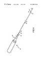
- a conventional endoscope 10shown in FIG. 1, has an insertion tube 12 connected at its proximal end 14 to a handle or control body 16 .
- the insertion tube 12is adapted to be inserted into a patient's body cavity to perform a selected therapeutic or diagnostic procedure.
- the insertion tube 12contains an imaging system 18 having optical fibers or the like extending along the length of the insertion tube and terminating at a viewing window 19 in the insertion tube's distal end 20 .
- the imaging system 18conveys an image from the viewing window 19 to an eyepiece 22 on the control body 16 or to a monitor (not shown), so the user can see into a selected body cavity during an endoscopic procedure.
- the endoscope 10is described in greater detail in U.S. Pat. No. Re 34,110 and U.S. Pat. No. 4,646,722, which are incorporated herein by reference.
- Disposable endoscopic sheath assembliesare used to cover the insertion tube 12 and protect it from contaminating a patient during use. Accordingly, the sheath assemblies alleviate the problem and cost of cleaning and sterilizing the insertion tube 12 between endoscopic procedures.
- the sheaths and endoscopesare usable in medical applications and also in industrial applications, such as visually inspecting difficult to reach areas in an environment that could damage or contaminate the endoscope.
- a sheathed endoscopecan be used in an industrial area wherein the sheath protects the endoscope's insertion tube from adhesive or the like. As seen in FIG.
- a conventional sheath assembly 24shown partially cut away for illustrative purposes, includes a sheath 26 that surrounds the endoscope's insertion tube 12 .
- the sheath assembly 24may also contain one or more working channels 32 that extend along the insertion tube 12 and that are adapted to receive conventional endoscopic accessories therethrough without allowing the endoscope to contaminate the accessories during the endoscopic procedure.
- the sheath 26has a distal end portion 21 that includes an endcap 34 having a transparent window 28 positioned to cover the viewing window 19 at the insertion tube's distal end 20 when the sheath assembly 24 is installed.
- the endcap 34is sealably secured to the sheath's distal end portion 21 .
- the sheath 26 and endcap 34are commonly made from polymeric materials.
- the sheath 26can be made from an inelastic polymer, such as PVC, acrylic, polycarbonate, polyethylene terephthalate or other thermoplastic polyesters, or can be made from an elastomeric material. Both materials presently have advantages and disadvantages.
- the sheath 26can be formed with a thin wall (measuring 0.003 inches or less) and a small diameter (such as 0.5 mm). Inelastic materials tend to be clearer than the elastic materials, and can thus provide better visibility with less distortion.
- U.S. Pat. No. 5,443,781 to Saabteaches a method of forming an inelastic, disposable sheath with an integral, optically transparent window.
- Saabteaches forming the inelastic sheath by heating a sheet or film of optically transparent, inelastic, polymeric material until the material is malleable.
- a mandrel 35is thrust into the heated film 37 causing the film to stretch and to generally conform to the mandrel's shape.
- the heated film 37is formed into an inelastic closed-end sheath 39 having sidewalls 36 , a flange or collar 38 at its open proximal end 40 , and a closed distal end 42 .
- U.S. patent application Ser. No. 08/948,615which is incorporated herein by reference, further teaches a method of forming an inelastic, endoscopic sheath for use on an insertion tube having a complex cross-sectional shape. The process applies a differential pressure to the outside and inside of the sheath during fabrication to conform the sheath to the shape of a mandrel. By selecting a mandrel with the proper complex shape, the end cap can closely receive the corresponding insertion tube.
- Inelastic materialshave a number of disadvantages. Tight-fitting sheaths formed from inelastic materials may overly restrict bending when used with flexible insertion tubes. The insertion tube combined with the tight-fitting, inelastic sheath can only bend over a limited radius. If bent further, the sheath will either buckle, in the case of a thick-walled sheath, or the sheath material will become taught, in the case of a thin-walled sheath, preventing the insertion tube from bending further.
- the sheathis typically either baggy or must contain bending features, such as accordion-like baffles or the like, as taught by Saab, to allow the insertion tube to sufficiently bend. Both baggy sheaths and these additional bending features add to the cross-sectional size of the sheath during use, which may result in additional pain or discomfort to the patient.
- the sheath made from inelastic materialcannot be stretched axially onto the insertion tube.
- the inelastic sheathdoes not provide axial tension in the sheath urging the transparent window of the sheath against and in alignment with the viewing window at the insertion tube's distal end.
- additional featuressuch as connectors or helical coils, are typically built into the sheath. These features add to the complexity and cost of the sheath.
- Conventional elastic sheathshave been developed and used with imaging devices such as endoscopes to overcome the drawbacks associated with the inelastic sheaths described above and to provide additional benefits.
- conventional elastic sheathsare designed so the sheath will easily bend with the insertion tube without substantially affecting the insertion tube's bending characteristics.
- the elastic sheathcan also be stretched axially over the insertion tube to provide axial tension that retains the transparent window on the sheath against and in alignment with the viewing window at the insertion tube's distal end.
- the elastic sheathcan be designed to closely or tightly cover the insertion tube while still being able to bend with the insertion tube, so the elastic sheath does not need additional bending features.
- Elastic materialshowever, also have some disadvantages.
- conventional elastic sheathsare manufactured by extruding elastomeric material, that is, by pushing or forcing the elastomeric material through a die to form the desired structure.
- the extruded elastic sheathshave manufacturing limits that restrict the minimum wall thickness of the sheath. Efforts toward manufacturing such a sheath have typically resulted in the extruded material collapsing or wrinkling during the process. As a result, the extruded elastic sheath must be made with a relatively thick wall (i.e., greater than 0.006 inches). The thicker the sheath wall in a tight-fitting sheath, the greater the resistance to bending.
- elastic sheathscan also be complex and expensive to install onto the insertion tube.
- the elastic materials commonly used to manufacture the sheathhave high friction characteristics. As a result, it can be difficult to insert the insertion tube into the tight-fitting sheath because the insertion tube binds on the inner wall of the sheath.
- One solutionis to make the sheath with a diameter considerably larger than the insertion tube, so the sheath is baggy when installed on the insertion tube. Baggy sheaths, however, are undesirable in many endoscopic procedures because the sheath can be twisted, bunched, or misaligned relative to the insertion tube during the procedure.
- the baggy sheathcan also increase the diameter of the sheathed insertion tube, which can increase pain or discomfort to the patient.
- a tight-fitting sheath and endoscopeare specially designed to mate with a vacuum or inflation chamber (not shown) that radially expands the sheath while the insertion tube is inserted into the sheath. Once the insertion tube is fully inserted into the sheath, the vacuum or inflation pressure is removed and the sheath contracts to a size that fits closely over the insertion tube.
- the equipment needed for this installation processcan significantly increase the cost of endoscopic procedures.
- the present inventionprovides a method capable of forming thin-walled, elastic medical components from a heated, elastomeric sheet.
- the method of one particular embodiment of the inventionmay be used to manufacture small-diameter, thin-walled, elastic components, which has been problematic in the prior art.
- the method of forming a small-diameter, thin-walled elastic componentincludes heating a portion of the elastomeric sheet to a malleable temperature, pressing a distal end of an elongated forming tool on a first side of the elastomeric sheet at a location in the heated portion, stretching the heated portion with the forming tool until an elastic conforming portion is closely conformed to a portion of the forming tool, and removing the forming tool from the conforming portion of the sheet.
- the method of this embodimentcan be used to form an elastic sheath having a thin wall, a small diameter, and a length shorter than the length of the insertion tube so that the elastic sheath may be stretched longitudinally over the insertion tube.
- Embodiments of the present inventionalso provide a non-extruded thin-walled, elastic medical component made by the above-described process.
- FIG. 1is an isometric view of a prior art endoscope and endoscopic sheath assembly.
- FIG. 2is an isometric view of an inelastic film of the prior art being stretched by a mandrel.
- FIG. 3is an isometric view of a thin-walled, elastic sheath formed in accordance with one embodiment of the present invention placed in a relaxed state over an insertion tube of a flexible endoscope.
- FIG. 4is an isometric view of the sheath of FIG. 3 in an installed position stretched axially over the insertion tube of the flexible endoscope.
- FIG. 5is a partial cross-sectional view of the sheath and endoscope of FIG. 3 as viewed along Section 5 — 5 .
- FIG. 6is a partial cross-sectional view of the sheath and endoscope of FIG. 4 as viewed along Section 6 — 6 .
- FIG. 7is an isometric view of a sheet of partially-heated, elastomeric material and a support structure below a forming tool according an embodiment of the method of the present invention before the sheath has been formed.
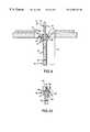
- FIG. 8is an enlarged cross-sectional view of FIG. 7 viewed along Section 8 — 8 after the sheath has been formed.
- FIG. 9is a cross-sectional view of another forming tool, a sheet of elastomeric material and a support structure according to another embodiment of the present invention after the sheath has been partially formed.
- FIG. 10is a partial, cross-sectional view of a proximal portion of the sheath of FIG. 9 after the sheath has been fully formed.
- FIGS. 3-6illustrate a medical device, for example an endoscope 50 having an insertion tube 52 , and a non-extruded, thin-walled, elastic sheath 54 formed in accordance with an embodiment of the invention.
- the elastic sheath 54is shaped and sized so its diameter is slightly larger than the insertion tube's diameter.
- the insertion tube 52can be easily inserted into the elastic sheath 54 until a distal end 56 of the insertion tube 52 just contacts a distal end 58 of the elastic sheath 54 .
- the elastic sheath 54 in FIG. 3is thus in its relaxed state, having a relaxed outside diameter, a relaxed inner diameter, and a relaxed wall thickness.
- the elastic sheath 54has a relaxed wall thickness in the range of up to and including approximately 0.009 inches, and preferably in the range of approximately 0.002 to 0.009 inches, inclusive, and more preferably in the range of approximately 0.002 to 0.006 inches, inclusive.
- FIGS. 4 and 6illustrate the elastic sheath 54 stretched axially over the insertion tube 52 until a proximal end 62 of the elastic sheath 54 aligns with a proximal end 60 of the insertion tube 52 .
- the elastic sheath 54is thus in a stretched, installed position, having a stretched outside diameter, a stretched inner diameter, and a stretched wall thickness.
- the stretched inner diameter, stretched outer diameter, and stretched wall thickness illustrated in FIG. 6are smaller than the similar dimensions relaxed in FIG. 5 .
- the extreme distal end 58 of the elastic sheath 54is sealably connected to an end cap 64 .
- the end cap 64can be integral with the elastic sheath 54 , or can be formed separately from the sheath and sealably attached thereto. In the latter case, the end cap 64 can be formed from a different material than the elastic sheath 54 , such as an inelastic polymer, in order to provide selected optical characteristics that may be different than those of the elastomeric material.
- the end cap 64can be formed from a clear, inelastic polymer to provide better visibility for use with an insertion tube 52 having a viewing window at its distal end 56 .
- the proximal end 62 of the elastic sheath 54terminates in a fitting, such as a collar 66 .
- a fittingsuch as a collar 66 .
- the collar 66can be integral with the sheath 54 or separate from and bonded to the elastic sheath 54 .
- the collar 66is sized and shaped to resiliently engage a headpiece 68 of the endoscope 50 to retain the sheath 54 on the insertion tube 52 during a procedure.
- FIGS. 7 and 8illustrate a method of manufacturing the thin-walled, elastic sheath 54 .
- the methoduses a sheet 70 of elastomeric material, such as a polyurethane, that contains friction-reducing additives or slip agents, such as wax, oil, silicon or silica.
- the sheet 70has an initial thickness of about 0.042 inches, although the thickness of the sheet 70 can vary based on the desired length and thickness of the sheath 54 being formed.
- the sheet 70 of the elastomeric materialis retained on a substantially flat support 72 having a central opening 74 extending therethrough.
- a portion of the elastomeric sheet 70 above the central openingis heated by a conventional heating device to a selected malleable temperature to form a malleable, heated portion 75 of the sheet 70 .
- a forming tool 76is then pressed into the heated portion 75 in a direction substantially normal to the plane of the sheet 70 , illustrated by the direction 1 .
- the forming tool 76has a generally circular cross-section.
- the forming tool 76could also have an oval, polygonal or other suitable cross-sectional shape.
- the elastomeric sheet 70stretches beyond its modulus of elasticity to form an elongated, thin-walled protrusion 78 (FIG. 8 ).
- the protrusion 78will eventually become all or a portion of the sheath 54 , as the excess material from the elastomeric sheet 70 is trimmed from the protrusion 78 .
- the protrusion 78has an open proximal portion 80 , a closed distal portion 82 spaced away from the open proximal portion 80 , and sidewalls 84 extending between the proximal and distal portions.
- the closed distal portion 82 and the sidewalls 84define an interior 86 of the protrusion 78 .
- the interior 86 of a conforming portion 87 at the distal portion 82 of the protrusion 78begins to closely conform to the outer shape of the forming tool.
- the conforming portion 87 of the protrusion 78progressively conforms to more of the length of the forming tool 75 .
- the forming tool 76is moved in the direction I until the length of the conforming portion 87 of the protrusion 78 is at least as long as the desired length of the elastic sheath 54 being formed.
- the elastic sheath 54can be as long as the insertion tube 52 for which it will be used, or it can be shorter than the insertion tube 52 (FIG. 5) to allow the elastic sheath 54 to be stretched axially over the insertion tube when installed.
- the forming tool 76can be stopped when the conforming portion 87 is at the desired length, or it can be moved further if desired to reduce the thickness of the sidewalls 84 .
- the thickness of the sidewalls 84 in one embodimentis in the range of approximately 0.002 to 0.009 inches, inclusive, and preferably in the range of approximately 0.002 to 0.006 inches, inclusive, or can be thinner than 0.002 inches.
- the forming tool 76is removed from the protrusion 78 and the protrusion is cut to separate the elastic sheath 54 from the elastomeric sheet 70 .
- the distal portion 82 of the protrusion 78can be left on what is now the elastic sheath 54 , or it can be removed and replaced with an end cap 64 (FIG. 6 ). If needed during manufacturing, the sheath 54 can then be trimmed at the distal end to the desired length before attaching the end cap.
- the elastomeric material used with the above embodiment of the present inventionis a thermoplastic, elastomeric material, such as polyurethane containing one or more conventional slip agents, such as wax, oil, silicone or silica.
- slip agentsare commonly used in the field of elastomeric materials, and an individual having ordinary skill in such an art will understand how to treat the elastomeric material to provide the desired properties for reduced friction.
- the treated elastomeric materialallows for small diameter, thin-walled elastic medical components that can be easily, inexpensively, and quickly manufactured.
- Embodiments of the present inventionhave a number of advantages over the sheaths of the prior art and the methods of making such sheaths. Because the elastomeric material is allowed to cool on the forming tool, the forming tool prevents the sheath from collapsing and sticking to itself while the elastomeric material is heated and tacky. This is an improvement over traditional extruded sheaths that could collapse during forming. If the sheath collapsed while the elastomeric material was hot and tacky, the sheath could be ruined.
- the elastic sheath 54is made from an elastomeric material treated with slip agents, the sheath can be formed with a relaxed inner diameter only slightly larger than an outside diameter of the insertion tube 52 and still be easily installed.
- the slip agentsallow the insertion tube to be easily inserted into the elastic sheath 54 without the distal end 56 of the insertion tube 52 binding, catching, or excessively distorting the elastic sheath 54 during installation.
- baggy sheathscan be eliminated.
- the need for additional equipment and features previously used to radially expand the tight-fitting, elastic sheath during installationare also eliminated.
- the elastic sheath 54is made from an elastomeric material, the diameter and wall thickness of the elastic sheath 54 decrease as the sheath is stretched axially over the insertion tube. Accordingly, the overall cross-section of the sheathed insertion tube may be minimized, thereby reducing the pain or discomfort experienced by a patient. Stretching the sheath also creates an axial restoring force in the elastomeric material which retains the end cap 64 at the distal end 58 of the elastic sheath 54 in contact and alignment with the distal end 56 of the insertion tube 52 .
- the elastic sheath 54 and the method of making the sheathare discussed herein with reference to an endoscope 50 , the method of the present invention is equally applicable to other medical components.
- the medical component in alternate embodimentscan be a catheter, optical imaging medical equipment, and non-optical imaging medical equipment.
- FIGS. 9 and 10illustrate an alternate embodiment of the method of the present invention.
- the forming tool 176has a tapered annular portion 177 at a point selected to correspond to a proximal end 180 of the elastic sheath 178 .
- the annular portion 177is provided in this embodiment in order to form an integral collar 185 (FIG. 10) at the sheath's proximal end 180 .
- a radially inward forceis applied to the sidewalls 184 to force the sidewalls against an outer surface the annular portion 177 .
- the radially inward forceis applied to the sidewalls 184 by a vacuum source (not shown) attached to a vacuum port 179 in the forming tool 176 .
- a partial vacuumis applied to the interior 186 of the sheath 178 via a number of ports 181 in the forming tool 176 .
- a radially inward forceis applied by pressing on the exterior of the sheath's sidewalls.
- the outer surface 183 of the forming tool's annular portion 177has a plurality of passages 190 into which a portion of the sidewalls 184 is drawn when the radially inward force is applied.
- the passages 190are shaped and sized to form retention members 189 in the proximal end 180 of the sheath 178 that releasably engage the distal end of the endoscope control body (not shown).
- the passages 190are shaped into annular grooves extending about the annular portion 177 .
- the retention members 189are formed into annular inward projections.
- the elastic sheath 178is formed with an integral proximal fitting used for retaining the sheath on the endoscope in the installed position.
- the retention members 189are annular in shape and have rectilinear cross-sections. The retention members 189 , however, can have other shapes and sizes.
- the cooled, elastic sheath 178is then removed from the forming tool 176 and the elastic sheath 178 is trimmed or cut near the proximal end 180 to remove excess material from the sheath 178 .
- the sheath's distal end 182may also be trimmed, and an end cap, such as that illustrated in FIGS. 5 and 6, is adhered or otherwise connected to the distal end 182 .
- the sheath's distal end 182extends over an outer portion 196 of the endcap and is sealably bonded in place.
- the sheath's distal end 182is sealably bonded to the inside of the endcap.
- the sheath 178is then ready for use with an endoscope to perform a selected endoscopic procedure without contaminating the endoscope's insertion tube.
Landscapes
- Life Sciences & Earth Sciences (AREA)
- Health & Medical Sciences (AREA)
- Engineering & Computer Science (AREA)
- Surgery (AREA)
- Heart & Thoracic Surgery (AREA)
- Medical Informatics (AREA)
- Nuclear Medicine, Radiotherapy & Molecular Imaging (AREA)
- Optics & Photonics (AREA)
- Pathology (AREA)
- Radiology & Medical Imaging (AREA)
- Physics & Mathematics (AREA)
- Biomedical Technology (AREA)
- Veterinary Medicine (AREA)
- Biophysics (AREA)
- Molecular Biology (AREA)
- Animal Behavior & Ethology (AREA)
- General Health & Medical Sciences (AREA)
- Public Health (AREA)
- Manufacturing & Machinery (AREA)
- Mechanical Engineering (AREA)
- Endoscopes (AREA)
- Shaping By String And By Release Of Stress In Plastics And The Like (AREA)
- Diaphragms And Bellows (AREA)
- Shaping Of Tube Ends By Bending Or Straightening (AREA)
Abstract
Description
Claims (4)
Priority Applications (9)
| Application Number | Priority Date | Filing Date | Title |
|---|---|---|---|
| US09/235,355US6350231B1 (en) | 1999-01-21 | 1999-01-21 | Apparatus and method for forming thin-walled elastic components from an elastomeric material |
| AT00906562TATE265922T1 (en) | 1999-01-21 | 2000-01-21 | THIN-WALLED ELASTIC COVER MADE OF ELASTOMER MATERIAL |
| EP00906562AEP1148988B1 (en) | 1999-01-21 | 2000-01-21 | Thin-walled elastic sheath from an elastomeric material |
| DE60010430TDE60010430T2 (en) | 1999-01-21 | 2000-01-21 | THIN-WALLED ELASTIC COVER MADE OF ELASTOMERIC MATERIAL |
| AU28220/00AAU765296B2 (en) | 1999-01-21 | 2000-01-21 | Apparatus and method for forming thin-walled elastic components from an elastomeric material |
| PCT/IB2000/000263WO2000042900A2 (en) | 1999-01-21 | 2000-01-21 | Forming thin-walled elastic components from an elastomeric material |
| ES00906562TES2220405T3 (en) | 1999-01-21 | 2000-01-21 | ELASTIC WALL ELASTIC HOSE OF ELASTOMERIC MATERIAL. |
| US09/611,628US6530881B1 (en) | 1999-01-21 | 2000-07-07 | Sheath apparatus for endoscopes and methods for forming same |
| US09/930,712US6733440B2 (en) | 1999-01-21 | 2001-08-14 | Apparatus and method for forming thin-walled elastic components from an elastomeric material |
Applications Claiming Priority (1)
| Application Number | Priority Date | Filing Date | Title |
|---|---|---|---|
| US09/235,355US6350231B1 (en) | 1999-01-21 | 1999-01-21 | Apparatus and method for forming thin-walled elastic components from an elastomeric material |
Related Child Applications (2)
| Application Number | Title | Priority Date | Filing Date |
|---|---|---|---|
| US09/611,628Continuation-In-PartUS6530881B1 (en) | 1999-01-21 | 2000-07-07 | Sheath apparatus for endoscopes and methods for forming same |
| US09/930,712DivisionUS6733440B2 (en) | 1999-01-21 | 2001-08-14 | Apparatus and method for forming thin-walled elastic components from an elastomeric material |
Publications (1)
| Publication Number | Publication Date |
|---|---|
| US6350231B1true US6350231B1 (en) | 2002-02-26 |
Family
ID=22885153
Family Applications (2)
| Application Number | Title | Priority Date | Filing Date |
|---|---|---|---|
| US09/235,355Expired - LifetimeUS6350231B1 (en) | 1999-01-21 | 1999-01-21 | Apparatus and method for forming thin-walled elastic components from an elastomeric material |
| US09/930,712Expired - LifetimeUS6733440B2 (en) | 1999-01-21 | 2001-08-14 | Apparatus and method for forming thin-walled elastic components from an elastomeric material |
Family Applications After (1)
| Application Number | Title | Priority Date | Filing Date |
|---|---|---|---|
| US09/930,712Expired - LifetimeUS6733440B2 (en) | 1999-01-21 | 2001-08-14 | Apparatus and method for forming thin-walled elastic components from an elastomeric material |
Country Status (7)
| Country | Link |
|---|---|
| US (2) | US6350231B1 (en) |
| EP (1) | EP1148988B1 (en) |
| AT (1) | ATE265922T1 (en) |
| AU (1) | AU765296B2 (en) |
| DE (1) | DE60010430T2 (en) |
| ES (1) | ES2220405T3 (en) |
| WO (1) | WO2000042900A2 (en) |
Cited By (53)
| Publication number | Priority date | Publication date | Assignee | Title |
|---|---|---|---|---|
| US20030008083A1 (en)* | 1997-10-10 | 2003-01-09 | Harhen E. Paul | Methods for forming complex-shaped components in a heated polymeric film |
| US20040039250A1 (en)* | 2002-05-28 | 2004-02-26 | David Tholfsen | Guidewire delivery of implantable bronchial isolation devices in accordance with lung treatment |
| US6733440B2 (en)* | 1999-01-21 | 2004-05-11 | Vision Sciences, Inc. | Apparatus and method for forming thin-walled elastic components from an elastomeric material |
| US6761684B1 (en)* | 2000-08-10 | 2004-07-13 | Linvatec Corporation | Endoscope tip protection system |
| US20040243393A1 (en)* | 2003-05-29 | 2004-12-02 | Microsoft Corporation | Semantic object synchronous understanding implemented with speech application language tags |
| US20050107668A1 (en)* | 1999-10-14 | 2005-05-19 | Scimed Life Systems, Inc. | Endoscopic instrument system having reduced backlash control wire action |
| US20050283048A1 (en)* | 2001-10-19 | 2005-12-22 | Visionscope, Llc | Portable imaging system employing a miniature endoscope |
| US20060149127A1 (en)* | 2004-12-30 | 2006-07-06 | Seddiqui Fred R | Disposable multi-lumen catheter with reusable stylet |
| US20070015989A1 (en)* | 2005-07-01 | 2007-01-18 | Avantis Medical Systems, Inc. | Endoscope Image Recognition System and Method |
| US20070142711A1 (en)* | 2005-12-13 | 2007-06-21 | Lex Bayer | Detachable Imaging Device, Endoscope Having A Detachable Imaging Device, And Method of Configuring Such An Endoscope |
| US20070153386A1 (en)* | 2004-08-23 | 2007-07-05 | Olympus Corporation | Observation system |
| US20070167681A1 (en)* | 2001-10-19 | 2007-07-19 | Gill Thomas J | Portable imaging system employing a miniature endoscope |
| US20070177008A1 (en)* | 2005-01-05 | 2007-08-02 | Avantis Medical, Inc. | Endoscope with an imaging catheter assembly and method of configuring an endoscope |
| US20070185384A1 (en)* | 2006-01-23 | 2007-08-09 | Avantis Medical Systems, Inc. | Endoscope |
| US20070270642A1 (en)* | 2006-05-19 | 2007-11-22 | Avantis Medical Systems, Inc. | System and method for producing and improving images |
| US20070293720A1 (en)* | 2005-01-05 | 2007-12-20 | Avantis Medical Systems, Inc. | Endoscope assembly and method of viewing an area inside a cavity |
| US20080021274A1 (en)* | 2005-01-05 | 2008-01-24 | Avantis Medical Systems, Inc. | Endoscopic medical device with locking mechanism and method |
| US20080033450A1 (en)* | 2006-08-04 | 2008-02-07 | Lex Bayer | Surgical Port With Embedded Imaging Device |
| US20080064925A1 (en)* | 2001-10-19 | 2008-03-13 | Gill Thomas J | Portable imaging system employing a miniature endoscope |
| US20080130108A1 (en)* | 2005-01-05 | 2008-06-05 | Avantis Medical Systems, Inc. | Endoscope assembly with a polarizing filter |
| US20080253686A1 (en)* | 2007-04-10 | 2008-10-16 | Avantis Medical Systems, Inc. | Method and Device for Examining or Imaging an Interior Surface of a Cavity |
| US20090213211A1 (en)* | 2007-10-11 | 2009-08-27 | Avantis Medical Systems, Inc. | Method and Device for Reducing the Fixed Pattern Noise of a Digital Image |
| US20090231419A1 (en)* | 2007-02-06 | 2009-09-17 | Avantis Medical Systems, Inc. | Endoscope Assembly and Method of Performing a Medical Procedure |
| US7736301B1 (en)* | 2001-12-18 | 2010-06-15 | Advanced Cardiovascular Systems, Inc. | Rotatable ferrules and interfaces for use with an optical guidewire |
| US20100199448A1 (en)* | 2009-02-06 | 2010-08-12 | Endoclear, Llc | Devices for cleaning endotracheal tubes |
| US20110023885A1 (en)* | 2009-02-06 | 2011-02-03 | Endoclear, Llc | Mechanically-actuated endotracheal tube cleaning device |
| US7942814B2 (en) | 2001-10-19 | 2011-05-17 | Visionscope Technologies Llc | Miniature endoscope with imaging fiber system |
| US20110130834A1 (en)* | 2001-10-11 | 2011-06-02 | Pulmonx Corporation | Bronchial flow control devices and methods of use |
| US20110152617A1 (en)* | 2009-12-22 | 2011-06-23 | Tyco Healthcare Group Lp | Endoscope cover fixing device and fixing system |
| US20110198777A1 (en)* | 2010-02-17 | 2011-08-18 | Der-Lin Liou | Method for manufacturing seamless thin-walled articles with thermoplastic materials |
| EP2386240A2 (en) | 2010-05-12 | 2011-11-16 | Q Park Medical Limited | Sheath for protecting endoscope probe |
| US8287446B2 (en) | 2006-04-18 | 2012-10-16 | Avantis Medical Systems, Inc. | Vibratory device, endoscope having such a device, method for configuring an endoscope, and method of reducing looping of an endoscope |
| US8317689B1 (en) | 1999-09-13 | 2012-11-27 | Visionscope Technologies Llc | Miniature endoscope system |
| US8872906B2 (en) | 2005-01-05 | 2014-10-28 | Avantis Medical Systems, Inc. | Endoscope assembly with a polarizing filter |
| USD731652S1 (en) | 2014-02-19 | 2015-06-09 | Tidi Products, Llc | Dental curing light sleeve |
| WO2015120348A1 (en) | 2014-02-06 | 2015-08-13 | Dentsply International Inc. | Inspection of dental roots and the endodontic cavity space therein |
| US9248266B2 (en) | 2013-12-17 | 2016-02-02 | Biovision Technologies, Llc | Method of performing a sphenopalatine ganglion block procedure |
| US9433468B2 (en) | 2013-10-04 | 2016-09-06 | Tidi Products, Llc | Sheath for a medical or dental instrument |
| US9445714B2 (en) | 2010-03-29 | 2016-09-20 | Endoclear Llc | Endotracheal tube coupling adapters |
| US9516995B2 (en) | 2013-12-17 | 2016-12-13 | Biovision Technologies, Llc | Surgical device for performing a sphenopalatine ganglion block procedure |
| US9694163B2 (en) | 2013-12-17 | 2017-07-04 | Biovision Technologies, Llc | Surgical device for performing a sphenopalatine ganglion block procedure |
| US10004863B2 (en) | 2012-12-04 | 2018-06-26 | Endoclear Llc | Closed suction cleaning devices, systems and methods |
| US10016575B2 (en) | 2014-06-03 | 2018-07-10 | Endoclear Llc | Cleaning devices, systems and methods |
| US10016580B2 (en) | 2013-12-17 | 2018-07-10 | Biovision Technologies, Llc | Methods for treating sinus diseases |
| US10389921B2 (en) | 2015-08-31 | 2019-08-20 | Panasonic Corporation | Endoscope |
| US10456164B2 (en) | 2017-10-02 | 2019-10-29 | URO-1, Inc. | Anti-microbial medical injection assemblies for onabotulinumtoxina delivery and methods of use thereof |
| US10525240B1 (en) | 2018-06-28 | 2020-01-07 | Sandler Scientific LLC | Sino-nasal rinse delivery device with agitation, flow-control and integrated medication management system |
| US10709317B2 (en) | 2018-10-04 | 2020-07-14 | PraesidioDyne, LLC | Clamp assembly for disposable endoscopic sheaths |
| US10722322B2 (en) | 2010-03-29 | 2020-07-28 | Endoclear Llc | Distal airway cleaning devices |
| US11376031B2 (en) | 2015-10-20 | 2022-07-05 | Lumendi Ltd. | Medical instruments for performing minimally-invasive procedures |
| US11446081B2 (en) | 2015-10-20 | 2022-09-20 | Lumedi Ltd. | Medical instruments for performing minimally-invasive procedures |
| US11504104B2 (en) | 2015-10-20 | 2022-11-22 | Lumendi Ltd. | Medical instruments for performing minimally-invasive procedures |
| US12419658B2 (en) | 2015-10-20 | 2025-09-23 | Lumendi AG | Medical instruments for performing minimally-invasive procedures |
Families Citing this family (27)
| Publication number | Priority date | Publication date | Assignee | Title |
|---|---|---|---|---|
| AU2000265350A1 (en)* | 2000-08-10 | 2002-02-25 | Vision Sciences, Inc. | Apparatus and method for forming complex-shaped components in a heated polymericfilm |
| US20020059629A1 (en)* | 2000-08-21 | 2002-05-16 | Markel Steven O. | Detection and recognition of data receiver to facilitate proper transmission of enhanced data |
| US20040199199A1 (en)* | 2003-04-02 | 2004-10-07 | Scimed Life Systems, Inc. | Filter and method of making a filter |
| GB0318740D0 (en)* | 2003-08-09 | 2003-09-10 | Orr Paul | Flexible fibreoptic endoscope |
| WO2005058147A1 (en)* | 2003-12-18 | 2005-06-30 | Patents Exploitation Company B.V. | Flexible protective sheath for an endoscope |
| US20070185383A1 (en)* | 2006-02-08 | 2007-08-09 | Vision-Sciences, Inc. | Tapered endoscopic protective sheath |
| WO2008048967A1 (en)* | 2006-10-16 | 2008-04-24 | University Of Rochester | Tripodal cyclohexane derivatives and their use as carbohydrate receptors |
| DE102007008099B4 (en) | 2007-02-19 | 2021-05-20 | Ingoscope Systems Gmbh | Tube arrangement for an endoscope |
| US20090294313A1 (en)* | 2008-02-08 | 2009-12-03 | Pacey Jack | Single-use medical equipment package cover |
| DE102008059633A1 (en)* | 2008-11-28 | 2010-06-02 | Aesculap Ag | Medical endoscope, has tubular sterile sleeve adjusted in proximal direction by helical spring such that lateral window rests at plane window that is provided at distal end of tubular shaft, where lateral window is connected to plane window |
| KR101493382B1 (en) | 2009-01-14 | 2015-02-13 | 삼성전자 주식회사 | Robot |
| WO2010103501A1 (en)* | 2009-03-09 | 2010-09-16 | Flip Technologies Limited | A device for protecting a catheter |
| US20110118551A1 (en)* | 2009-11-14 | 2011-05-19 | SPI Surgical, Inc. | Collateral soft tissue protection surgical device |
| US8986201B2 (en) | 2009-11-14 | 2015-03-24 | Spiway Llc | Surgical tissue protection sheath |
| US9451981B2 (en) | 2009-11-14 | 2016-09-27 | Spiway Llc | Surgical tissue protection sheath |
| US9011326B2 (en) | 2009-11-14 | 2015-04-21 | Spiway Llc | Soft tissue shield for trans-orbital surgery |
| EP4000497A1 (en) | 2011-02-16 | 2022-05-25 | The General Hospital Corporation | Optical coupler for an endoscope |
| US20140046137A1 (en)* | 2012-08-08 | 2014-02-13 | Ronda Duke Brown | Retractor Cover Apparatus and Associated Methods |
| US11039735B2 (en) | 2013-03-13 | 2021-06-22 | Spiway Llc | Surgical tissue protection sheath |
| US10986984B2 (en) | 2013-03-13 | 2021-04-27 | Spiway Llc | Surgical tissue protection sheath |
| US10588642B2 (en) | 2014-05-15 | 2020-03-17 | Gauthier Biomedical, Inc. | Molding process and products formed thereby |
| US9459442B2 (en) | 2014-09-23 | 2016-10-04 | Scott Miller | Optical coupler for optical imaging visualization device |
| US10548467B2 (en) | 2015-06-02 | 2020-02-04 | GI Scientific, LLC | Conductive optical element |
| WO2017015480A1 (en) | 2015-07-21 | 2017-01-26 | GI Scientific, LLC | Endoscope accessory with angularly adjustable exit portal |
| US20190231177A1 (en)* | 2018-01-31 | 2019-08-01 | UVision360, Inc. | Flexible imaging window |
| US11583313B1 (en) | 2018-12-06 | 2023-02-21 | Spiway Llc | Surgical access sheath and methods of use |
| WO2025000087A1 (en)* | 2023-06-29 | 2025-01-02 | Daxsonics Ultrasound Inc. | Ultrasound endoscope with conformal sheath and methods of assembly therof |
Citations (11)
| Publication number | Priority date | Publication date | Assignee | Title |
|---|---|---|---|---|
| US3794091A (en) | 1971-10-07 | 1974-02-26 | Med General Inc | Sterile sheath for surgical illuminator |
| US3809072A (en) | 1971-10-07 | 1974-05-07 | Med General Inc | Sterile sheath apparatus for fiber optic illuminator with compatible lens |
| US4886049A (en)* | 1988-05-17 | 1989-12-12 | Darras Robert L | Medical instrument cover |
| US5237984A (en)* | 1991-06-24 | 1993-08-24 | Xomed-Treace Inc. | Sheath for endoscope |
| US5337734A (en) | 1992-10-29 | 1994-08-16 | Advanced Polymers, Incorporated | Disposable sheath with optically transparent window formed continuously integral therewith |
| US5419310A (en)* | 1992-11-03 | 1995-05-30 | Vision Sciences, Inc. | Partially inflated protective endoscope sheath |
| US5483951A (en)* | 1994-02-25 | 1996-01-16 | Vision-Sciences, Inc. | Working channels for a disposable sheath for an endoscope |
| US5505686A (en)* | 1994-05-05 | 1996-04-09 | Imagyn Medical, Inc. | Endoscope with protruding member and method of utilizing the same |
| US5643175A (en) | 1992-09-01 | 1997-07-01 | Adair; Edwin L. | Sterilizable endoscope with separable disposable tube assembly |
| US5695454A (en)* | 1994-06-30 | 1997-12-09 | Mourkidou; Sotiria | Cover for a laryngoscope |
| US5718861A (en) | 1993-12-20 | 1998-02-17 | C. R. Bard, Incorporated | Method of forming intra-aortic balloon catheters |
Family Cites Families (22)
| Publication number | Priority date | Publication date | Assignee | Title |
|---|---|---|---|---|
| JPS5216630Y2 (en) | 1971-07-22 | 1977-04-14 | ||
| US4143423A (en) | 1977-10-25 | 1979-03-13 | Sternlieb Jack J | Surgical lubricants |
| US4459255A (en)* | 1982-10-18 | 1984-07-10 | Sheridan David S | Catheter distal end finishing method |
| US4551292A (en)* | 1984-04-05 | 1985-11-05 | Angiomedics, Inc. | Method for making a catheter with a soft, deformable tip |
| US4646722A (en) | 1984-12-10 | 1987-03-03 | Opielab, Inc. | Protective endoscope sheath and method of installing same |
| US4794920A (en) | 1987-07-14 | 1989-01-03 | Robichaud David M | Birth control device |
| US4881553A (en) | 1987-11-20 | 1989-11-21 | Grossman Richard A | Mesh reinforced condom |
| USRE34110E (en) | 1988-04-22 | 1992-10-27 | Opielab, Inc. | Endoscope for use with a disposable sheath |
| US5482053A (en) | 1989-06-06 | 1996-01-09 | Kelly; Patrick D. | Condom lubricants containing zinc as an anti-viral agent |
| US4971071A (en) | 1989-07-14 | 1990-11-20 | Stanley Hochfeld | Conductive condom |
| US5111831A (en) | 1990-02-16 | 1992-05-12 | Foggia David J | Scrotum supporting condom with retention means |
| US5098755A (en) | 1990-11-21 | 1992-03-24 | Tanquary Albert C | Textured thermoplastic elastomeric film, articles comprising same, and method of making such textured thermoplastic elastomeric film and articles |
| US5386817A (en)* | 1991-06-10 | 1995-02-07 | Endomedical Technologies, Inc. | Endoscope sheath and valve system |
| US5881386A (en)* | 1993-12-23 | 1999-03-16 | Maxxim Medical, Inc. | Flexible polyvinyl chloride article and method of making |
| US5429118A (en) | 1994-04-07 | 1995-07-04 | Cook (Canada) Incorporated | Disposable medical scope sheath |
| US5513654A (en) | 1994-06-10 | 1996-05-07 | New Designs Corporation | Slip-resistant contraceptive male condom |
| US5570692A (en) | 1995-05-19 | 1996-11-05 | Hayashi Denki Co. Ltd. | Ultrasonic doppler blood flow detector for hemorrhoid artery ligation |
| GB9610765D0 (en)* | 1996-05-23 | 1996-07-31 | Axon Anthony T R | Improvements in or relating to endoscopes |
| US6306514B1 (en)* | 1996-12-31 | 2001-10-23 | Ansell Healthcare Products Inc. | Slip-coated elastomeric flexible articles and their method of manufacture |
| US6016570A (en)* | 1998-05-11 | 2000-01-25 | Maxxim Medical, Inc. | Powderfree medical glove |
| US6350231B1 (en)* | 1999-01-21 | 2002-02-26 | Vision Sciences, Inc. | Apparatus and method for forming thin-walled elastic components from an elastomeric material |
| US6270484B1 (en) | 1999-02-17 | 2001-08-07 | Inbae Yoon | Safety penetrating instrument with expandible portion and method of penetrating anatomical cavity |
- 1999
- 1999-01-21USUS09/235,355patent/US6350231B1/ennot_activeExpired - Lifetime
- 2000
- 2000-01-21ATAT00906562Tpatent/ATE265922T1/ennot_activeIP Right Cessation
- 2000-01-21EPEP00906562Apatent/EP1148988B1/ennot_activeExpired - Lifetime
- 2000-01-21AUAU28220/00Apatent/AU765296B2/ennot_activeExpired
- 2000-01-21DEDE60010430Tpatent/DE60010430T2/ennot_activeExpired - Lifetime
- 2000-01-21ESES00906562Tpatent/ES2220405T3/ennot_activeExpired - Lifetime
- 2000-01-21WOPCT/IB2000/000263patent/WO2000042900A2/enactiveIP Right Grant
- 2001
- 2001-08-14USUS09/930,712patent/US6733440B2/ennot_activeExpired - Lifetime
Patent Citations (12)
| Publication number | Priority date | Publication date | Assignee | Title |
|---|---|---|---|---|
| US3794091A (en) | 1971-10-07 | 1974-02-26 | Med General Inc | Sterile sheath for surgical illuminator |
| US3809072A (en) | 1971-10-07 | 1974-05-07 | Med General Inc | Sterile sheath apparatus for fiber optic illuminator with compatible lens |
| US4886049A (en)* | 1988-05-17 | 1989-12-12 | Darras Robert L | Medical instrument cover |
| US5237984A (en)* | 1991-06-24 | 1993-08-24 | Xomed-Treace Inc. | Sheath for endoscope |
| US5643175A (en) | 1992-09-01 | 1997-07-01 | Adair; Edwin L. | Sterilizable endoscope with separable disposable tube assembly |
| US5337734A (en) | 1992-10-29 | 1994-08-16 | Advanced Polymers, Incorporated | Disposable sheath with optically transparent window formed continuously integral therewith |
| US5443781A (en) | 1992-10-29 | 1995-08-22 | Saab; Mark A. | Method of preparing disposable sheath with optically transparent windows formed continuously integral therewith |
| US5419310A (en)* | 1992-11-03 | 1995-05-30 | Vision Sciences, Inc. | Partially inflated protective endoscope sheath |
| US5718861A (en) | 1993-12-20 | 1998-02-17 | C. R. Bard, Incorporated | Method of forming intra-aortic balloon catheters |
| US5483951A (en)* | 1994-02-25 | 1996-01-16 | Vision-Sciences, Inc. | Working channels for a disposable sheath for an endoscope |
| US5505686A (en)* | 1994-05-05 | 1996-04-09 | Imagyn Medical, Inc. | Endoscope with protruding member and method of utilizing the same |
| US5695454A (en)* | 1994-06-30 | 1997-12-09 | Mourkidou; Sotiria | Cover for a laryngoscope |
Cited By (105)
| Publication number | Priority date | Publication date | Assignee | Title |
|---|---|---|---|---|
| US7025923B2 (en)* | 1997-10-10 | 2006-04-11 | Vision Sciences, Inc. | Methods for forming complex-shaped components in a heated polymeric film |
| US20030008083A1 (en)* | 1997-10-10 | 2003-01-09 | Harhen E. Paul | Methods for forming complex-shaped components in a heated polymeric film |
| US6733440B2 (en)* | 1999-01-21 | 2004-05-11 | Vision Sciences, Inc. | Apparatus and method for forming thin-walled elastic components from an elastomeric material |
| US8317689B1 (en) | 1999-09-13 | 2012-11-27 | Visionscope Technologies Llc | Miniature endoscope system |
| US8652028B2 (en)* | 1999-10-14 | 2014-02-18 | Boston Scientific Scimed, Inc. | Endoscopic instrument system having reduced backlash control wire action |
| US20050107668A1 (en)* | 1999-10-14 | 2005-05-19 | Scimed Life Systems, Inc. | Endoscopic instrument system having reduced backlash control wire action |
| US6761684B1 (en)* | 2000-08-10 | 2004-07-13 | Linvatec Corporation | Endoscope tip protection system |
| US20110130834A1 (en)* | 2001-10-11 | 2011-06-02 | Pulmonx Corporation | Bronchial flow control devices and methods of use |
| US7942814B2 (en) | 2001-10-19 | 2011-05-17 | Visionscope Technologies Llc | Miniature endoscope with imaging fiber system |
| US20080064925A1 (en)* | 2001-10-19 | 2008-03-13 | Gill Thomas J | Portable imaging system employing a miniature endoscope |
| US20070167681A1 (en)* | 2001-10-19 | 2007-07-19 | Gill Thomas J | Portable imaging system employing a miniature endoscope |
| US8038602B2 (en) | 2001-10-19 | 2011-10-18 | Visionscope Llc | Portable imaging system employing a miniature endoscope |
| US20050283048A1 (en)* | 2001-10-19 | 2005-12-22 | Visionscope, Llc | Portable imaging system employing a miniature endoscope |
| US10595710B2 (en) | 2001-10-19 | 2020-03-24 | Visionscope Technologies Llc | Portable imaging system employing a miniature endoscope |
| US11484189B2 (en) | 2001-10-19 | 2022-11-01 | Visionscope Technologies Llc | Portable imaging system employing a miniature endoscope |
| US7736301B1 (en)* | 2001-12-18 | 2010-06-15 | Advanced Cardiovascular Systems, Inc. | Rotatable ferrules and interfaces for use with an optical guidewire |
| US20050066974A1 (en)* | 2002-05-28 | 2005-03-31 | Antony Fields | Modification of lung region flow dynamics using flow control devices implanted in bronchial wall channels |
| US20040039250A1 (en)* | 2002-05-28 | 2004-02-26 | David Tholfsen | Guidewire delivery of implantable bronchial isolation devices in accordance with lung treatment |
| US20040243393A1 (en)* | 2003-05-29 | 2004-12-02 | Microsoft Corporation | Semantic object synchronous understanding implemented with speech application language tags |
| US20070153386A1 (en)* | 2004-08-23 | 2007-07-05 | Olympus Corporation | Observation system |
| US20060149127A1 (en)* | 2004-12-30 | 2006-07-06 | Seddiqui Fred R | Disposable multi-lumen catheter with reusable stylet |
| US8872906B2 (en) | 2005-01-05 | 2014-10-28 | Avantis Medical Systems, Inc. | Endoscope assembly with a polarizing filter |
| US20080021274A1 (en)* | 2005-01-05 | 2008-01-24 | Avantis Medical Systems, Inc. | Endoscopic medical device with locking mechanism and method |
| US20070177008A1 (en)* | 2005-01-05 | 2007-08-02 | Avantis Medical, Inc. | Endoscope with an imaging catheter assembly and method of configuring an endoscope |
| US8797392B2 (en) | 2005-01-05 | 2014-08-05 | Avantis Medical Sytems, Inc. | Endoscope assembly with a polarizing filter |
| US8289381B2 (en) | 2005-01-05 | 2012-10-16 | Avantis Medical Systems, Inc. | Endoscope with an imaging catheter assembly and method of configuring an endoscope |
| US20080130108A1 (en)* | 2005-01-05 | 2008-06-05 | Avantis Medical Systems, Inc. | Endoscope assembly with a polarizing filter |
| US20070293720A1 (en)* | 2005-01-05 | 2007-12-20 | Avantis Medical Systems, Inc. | Endoscope assembly and method of viewing an area inside a cavity |
| US20070015989A1 (en)* | 2005-07-01 | 2007-01-18 | Avantis Medical Systems, Inc. | Endoscope Image Recognition System and Method |
| US11529044B2 (en) | 2005-12-13 | 2022-12-20 | Psip Llc | Endoscope imaging device |
| US8182422B2 (en) | 2005-12-13 | 2012-05-22 | Avantis Medical Systems, Inc. | Endoscope having detachable imaging device and method of using |
| US20070142711A1 (en)* | 2005-12-13 | 2007-06-21 | Lex Bayer | Detachable Imaging Device, Endoscope Having A Detachable Imaging Device, And Method of Configuring Such An Endoscope |
| US20070185384A1 (en)* | 2006-01-23 | 2007-08-09 | Avantis Medical Systems, Inc. | Endoscope |
| US8235887B2 (en) | 2006-01-23 | 2012-08-07 | Avantis Medical Systems, Inc. | Endoscope assembly with retroscope |
| US10045685B2 (en) | 2006-01-23 | 2018-08-14 | Avantis Medical Systems, Inc. | Endoscope |
| US8287446B2 (en) | 2006-04-18 | 2012-10-16 | Avantis Medical Systems, Inc. | Vibratory device, endoscope having such a device, method for configuring an endoscope, and method of reducing looping of an endoscope |
| US8197399B2 (en) | 2006-05-19 | 2012-06-12 | Avantis Medical Systems, Inc. | System and method for producing and improving images |
| US20070270642A1 (en)* | 2006-05-19 | 2007-11-22 | Avantis Medical Systems, Inc. | System and method for producing and improving images |
| US20070279486A1 (en)* | 2006-05-19 | 2007-12-06 | Avantis Medical Systems, Inc. | Device and method for reducing effects of video artifacts |
| US8587645B2 (en) | 2006-05-19 | 2013-11-19 | Avantis Medical Systems, Inc. | Device and method for reducing effects of video artifacts |
| US8310530B2 (en) | 2006-05-19 | 2012-11-13 | Avantis Medical Systems, Inc. | Device and method for reducing effects of video artifacts |
| US20080033450A1 (en)* | 2006-08-04 | 2008-02-07 | Lex Bayer | Surgical Port With Embedded Imaging Device |
| US7927272B2 (en) | 2006-08-04 | 2011-04-19 | Avantis Medical Systems, Inc. | Surgical port with embedded imaging device |
| US20090231419A1 (en)* | 2007-02-06 | 2009-09-17 | Avantis Medical Systems, Inc. | Endoscope Assembly and Method of Performing a Medical Procedure |
| US10354382B2 (en) | 2007-04-10 | 2019-07-16 | Avantis Medical Systems, Inc. | Method and device for examining or imaging an interior surface of a cavity |
| US9044185B2 (en) | 2007-04-10 | 2015-06-02 | Avantis Medical Systems, Inc. | Method and device for examining or imaging an interior surface of a cavity |
| US9613418B2 (en) | 2007-04-10 | 2017-04-04 | Avantis Medical Systems, Inc. | Method and device for examining or imaging an interior surface of a cavity |
| US20080253686A1 (en)* | 2007-04-10 | 2008-10-16 | Avantis Medical Systems, Inc. | Method and Device for Examining or Imaging an Interior Surface of a Cavity |
| US8064666B2 (en) | 2007-04-10 | 2011-11-22 | Avantis Medical Systems, Inc. | Method and device for examining or imaging an interior surface of a cavity |
| US20090213211A1 (en)* | 2007-10-11 | 2009-08-27 | Avantis Medical Systems, Inc. | Method and Device for Reducing the Fixed Pattern Noise of a Digital Image |
| US8468637B2 (en) | 2009-02-06 | 2013-06-25 | Endoclear Llc | Mechanically-actuated endotracheal tube cleaning device |
| US9962233B2 (en) | 2009-02-06 | 2018-05-08 | Endoclear Llc | Body-inserted tube cleaning |
| US8382908B2 (en) | 2009-02-06 | 2013-02-26 | Endoclear, Llc | Methods for cleaning endotracheal tubes |
| US8534287B2 (en) | 2009-02-06 | 2013-09-17 | Endoclear, Llc | Methods for tracheostomy visualization |
| US8381345B2 (en) | 2009-02-06 | 2013-02-26 | Endoclear, Llc | Devices for cleaning endotracheal tubes |
| US8601633B2 (en) | 2009-02-06 | 2013-12-10 | Endoclear Llc | Cleaning of body-inserted medical tubes |
| US8157919B2 (en) | 2009-02-06 | 2012-04-17 | Endoclear, Llc | Methods for removing debris from medical tubes |
| US20100199448A1 (en)* | 2009-02-06 | 2010-08-12 | Endoclear, Llc | Devices for cleaning endotracheal tubes |
| US20100199999A1 (en)* | 2009-02-06 | 2010-08-12 | Vazales Brad E | Methods for cleaning endotracheal tubes |
| US10682203B2 (en) | 2009-02-06 | 2020-06-16 | Endoclear Llc | Methods of cleaning endotracheal tubes including light treatment |
| US20110023885A1 (en)* | 2009-02-06 | 2011-02-03 | Endoclear, Llc | Mechanically-actuated endotracheal tube cleaning device |
| US9095286B2 (en) | 2009-02-06 | 2015-08-04 | Endoclear Llc | Body-inserted tube cleaning |
| US10441380B2 (en) | 2009-02-06 | 2019-10-15 | Endoclear Llc | Body-inserted tube cleaning |
| US20110023887A1 (en)* | 2009-02-06 | 2011-02-03 | Endoclear, Llc | Methods for tracheostomy visualization |
| US9332891B2 (en) | 2009-02-06 | 2016-05-10 | Endoclear Llc | Tracheostomy visualization |
| US9386907B2 (en) | 2009-02-06 | 2016-07-12 | Endoclear Llc | Visualization systems and methods |
| US9398837B2 (en) | 2009-02-06 | 2016-07-26 | Endoclear Llc | Methods for confirming placement of endotracheal tubes |
| US20110023886A1 (en)* | 2009-02-06 | 2011-02-03 | Endoclear, Llc | Medical tube cleaning apparatus |
| US8458844B2 (en) | 2009-02-06 | 2013-06-11 | Endoclear, Llc | Medical tube cleaning apparatus |
| US9907624B2 (en) | 2009-02-06 | 2018-03-06 | Endoclear Llc | Body-inserted tube cleaning with suction |
| US9855111B2 (en) | 2009-02-06 | 2018-01-02 | Endoclear Llc | Methods of removing biofilm from endotracheal tubes |
| US9579012B2 (en) | 2009-02-06 | 2017-02-28 | Endoclear Llc | Visualized endotracheal tube placement systems |
| US20110023888A1 (en)* | 2009-02-06 | 2011-02-03 | Endoclear, Llc | Methods for removing debris from medical tubes |
| US20110152617A1 (en)* | 2009-12-22 | 2011-06-23 | Tyco Healthcare Group Lp | Endoscope cover fixing device and fixing system |
| US20110198777A1 (en)* | 2010-02-17 | 2011-08-18 | Der-Lin Liou | Method for manufacturing seamless thin-walled articles with thermoplastic materials |
| US9445714B2 (en) | 2010-03-29 | 2016-09-20 | Endoclear Llc | Endotracheal tube coupling adapters |
| US10722322B2 (en) | 2010-03-29 | 2020-07-28 | Endoclear Llc | Distal airway cleaning devices |
| EP2386240A2 (en) | 2010-05-12 | 2011-11-16 | Q Park Medical Limited | Sheath for protecting endoscope probe |
| US11173266B2 (en) | 2012-12-04 | 2021-11-16 | Endoclear Llc | Closed suction cleaning devices, systems and methods |
| US10004863B2 (en) | 2012-12-04 | 2018-06-26 | Endoclear Llc | Closed suction cleaning devices, systems and methods |
| US10821249B2 (en) | 2012-12-04 | 2020-11-03 | Endoclear Llc | Closed suction cleaning devices, systems and methods |
| US9433468B2 (en) | 2013-10-04 | 2016-09-06 | Tidi Products, Llc | Sheath for a medical or dental instrument |
| US11058855B2 (en) | 2013-12-17 | 2021-07-13 | Biovision Technologies, Llc | Surgical device for performing a sphenopalatine ganglion block procedure |
| US9510743B2 (en) | 2013-12-17 | 2016-12-06 | Biovision Technologies, Llc | Stabilized surgical device for performing a sphenopalatine ganglion block procedure |
| US9516995B2 (en) | 2013-12-17 | 2016-12-13 | Biovision Technologies, Llc | Surgical device for performing a sphenopalatine ganglion block procedure |
| US10420459B2 (en) | 2013-12-17 | 2019-09-24 | Biovision Technologies, Llc | Method of performing a sphenopalatine ganglion block procedure |
| US9839347B2 (en) | 2013-12-17 | 2017-12-12 | Biovision Technologies Llc | Method of performing a sphenopalatine ganglion block procedure |
| US9694163B2 (en) | 2013-12-17 | 2017-07-04 | Biovision Technologies, Llc | Surgical device for performing a sphenopalatine ganglion block procedure |
| US9248266B2 (en) | 2013-12-17 | 2016-02-02 | Biovision Technologies, Llc | Method of performing a sphenopalatine ganglion block procedure |
| US10016580B2 (en) | 2013-12-17 | 2018-07-10 | Biovision Technologies, Llc | Methods for treating sinus diseases |
| US10589072B2 (en) | 2013-12-17 | 2020-03-17 | Biovision Technologies, Llc | Methods for treating sinus diseases |
| US10046143B2 (en) | 2013-12-17 | 2018-08-14 | Biovision Technologies Llc | Surgical device for performing a sphenopalatine ganglion block procedure |
| WO2015120348A1 (en) | 2014-02-06 | 2015-08-13 | Dentsply International Inc. | Inspection of dental roots and the endodontic cavity space therein |
| USD731652S1 (en) | 2014-02-19 | 2015-06-09 | Tidi Products, Llc | Dental curing light sleeve |
| US10016575B2 (en) | 2014-06-03 | 2018-07-10 | Endoclear Llc | Cleaning devices, systems and methods |
| US10850062B2 (en) | 2014-06-03 | 2020-12-01 | Endoclear Llc | Cleaning devices, systems and methods |
| US10560612B2 (en) | 2015-08-31 | 2020-02-11 | Panasonic I-Pro Sensing Solutions Co., Ltd. | Endoscope |
| US10389921B2 (en) | 2015-08-31 | 2019-08-20 | Panasonic Corporation | Endoscope |
| US12419658B2 (en) | 2015-10-20 | 2025-09-23 | Lumendi AG | Medical instruments for performing minimally-invasive procedures |
| US11376031B2 (en) | 2015-10-20 | 2022-07-05 | Lumendi Ltd. | Medical instruments for performing minimally-invasive procedures |
| US11446081B2 (en) | 2015-10-20 | 2022-09-20 | Lumedi Ltd. | Medical instruments for performing minimally-invasive procedures |
| US11504104B2 (en) | 2015-10-20 | 2022-11-22 | Lumendi Ltd. | Medical instruments for performing minimally-invasive procedures |
| US10456164B2 (en) | 2017-10-02 | 2019-10-29 | URO-1, Inc. | Anti-microbial medical injection assemblies for onabotulinumtoxina delivery and methods of use thereof |
| US10525240B1 (en) | 2018-06-28 | 2020-01-07 | Sandler Scientific LLC | Sino-nasal rinse delivery device with agitation, flow-control and integrated medication management system |
| US10709317B2 (en) | 2018-10-04 | 2020-07-14 | PraesidioDyne, LLC | Clamp assembly for disposable endoscopic sheaths |
Also Published As
| Publication number | Publication date |
|---|---|
| ES2220405T3 (en) | 2004-12-16 |
| US20020013511A1 (en) | 2002-01-31 |
| AU765296B2 (en) | 2003-09-11 |
| AU2822000A (en) | 2000-08-07 |
| WO2000042900A3 (en) | 2000-11-02 |
| DE60010430T2 (en) | 2004-09-09 |
| EP1148988A2 (en) | 2001-10-31 |
| US6733440B2 (en) | 2004-05-11 |
| DE60010430D1 (en) | 2004-06-09 |
| WO2000042900A2 (en) | 2000-07-27 |
| ATE265922T1 (en) | 2004-05-15 |
| EP1148988B1 (en) | 2004-05-06 |
Similar Documents
| Publication | Publication Date | Title |
|---|---|---|
| US6350231B1 (en) | Apparatus and method for forming thin-walled elastic components from an elastomeric material | |
| US6530881B1 (en) | Sheath apparatus for endoscopes and methods for forming same | |
| US5483951A (en) | Working channels for a disposable sheath for an endoscope | |
| US10307042B2 (en) | Disposable sheath device | |
| US7025923B2 (en) | Methods for forming complex-shaped components in a heated polymeric film | |
| US9498108B1 (en) | Disposable sheath device | |
| US5685822A (en) | Endoscope with sheath retaining device | |
| US6174280B1 (en) | Sheath for protecting and altering the bending characteristics of a flexible endoscope | |
| US5702348A (en) | Disposable endoscopic sheath support and positioning assembly | |
| JP6884144B2 (en) | Mounting device for the top of the endoscope | |
| AU2003270939B2 (en) | Transparent dilation device and method of use | |
| US5025778A (en) | Endoscope with potential channels and method of using the same | |
| AU2016427268B2 (en) | Disposable sheath device | |
| EP1309266B1 (en) | Apparatus and method for forming complex-shaped components in a heated polymeric film | |
| WO2005058147A1 (en) | Flexible protective sheath for an endoscope |
Legal Events
| Date | Code | Title | Description |
|---|---|---|---|
| AS | Assignment | Owner name:VISION-SCIENCES, INC., MASSACHUSETTS Free format text:ASSIGNMENT OF ASSIGNORS INTEREST;ASSIGNORS:AILINGER, ROBERT;MARTONE, STEPHEN;REEL/FRAME:009932/0160 Effective date:19990408 | |
| STCF | Information on status: patent grant | Free format text:PATENTED CASE | |
| FPAY | Fee payment | Year of fee payment:4 | |
| FEPP | Fee payment procedure | Free format text:PAYOR NUMBER ASSIGNED (ORIGINAL EVENT CODE: ASPN); ENTITY STATUS OF PATENT OWNER: LARGE ENTITY | |
| FEPP | Fee payment procedure | Free format text:PAT HOLDER NO LONGER CLAIMS SMALL ENTITY STATUS, ENTITY STATUS SET TO UNDISCOUNTED (ORIGINAL EVENT CODE: STOL); ENTITY STATUS OF PATENT OWNER: LARGE ENTITY | |
| REFU | Refund | Free format text:REFUND - PAYMENT OF MAINTENANCE FEE, 8TH YR, SMALL ENTITY (ORIGINAL EVENT CODE: R2552); ENTITY STATUS OF PATENT OWNER: LARGE ENTITY Free format text:REFUND - 7.5 YR SURCHARGE - LATE PMT W/IN 6 MO, SMALL ENTITY (ORIGINAL EVENT CODE: R2555); ENTITY STATUS OF PATENT OWNER: LARGE ENTITY | |
| REMI | Maintenance fee reminder mailed | ||
| FPAY | Fee payment | Year of fee payment:8 | |
| SULP | Surcharge for late payment | Year of fee payment:7 | |
| FPAY | Fee payment | Year of fee payment:12 | |
| AS | Assignment | Owner name:COGENTIX MEDICAL, INC., MINNESOTA Free format text:CHANGE OF NAME;ASSIGNOR:VISION-SCIENCES, INC.;REEL/FRAME:040168/0531 Effective date:20150331 | |
| AS | Assignment | Owner name:COGENTIX MEDICAL, INC., MINNESOTA Free format text:CORRECTIVE ASSIGNMENT TO CORRECT THE INCORRECT PATENT NO. 6462294 PREVIOUSLY RECORDED AT REEL: 040168 FRAME: 0531. ASSIGNOR(S) HEREBY CONFIRMS THE CHANGE OF NAME;ASSIGNOR:VISION-SCIENCES, INC.;REEL/FRAME:041753/0414 Effective date:20150331 | |
| AS | Assignment | Owner name:JPMORGAN CHASE BANK, N.A., ILLINOIS Free format text:SECURITY INTEREST;ASSIGNORS:COGENTIX MEDICAL, INC.;UROPLASTY LLC;LABORIE MEDICAL TECHNOLOGIES CANADA ULC;REEL/FRAME:045609/0561 Effective date:20180423 | |
| AS | Assignment | Owner name:COGENTIX MEDICAL, INC., MINNESOTA Free format text:RELEASE OF SECURITY INTEREST IN PATENTS;ASSIGNOR:JPMORGAN CHASE BANK, N.A. AS ADMINISTRATIVE AGENT;REEL/FRAME:051906/0518 Effective date:20200212 Owner name:UROPLASTY LLC, MINNESOTA Free format text:RELEASE OF SECURITY INTEREST IN PATENTS;ASSIGNOR:JPMORGAN CHASE BANK, N.A. AS ADMINISTRATIVE AGENT;REEL/FRAME:051906/0518 Effective date:20200212 Owner name:LABORIE MEDICAL TECHNOLOGIES CANADA ULC, CANADA Free format text:RELEASE OF SECURITY INTEREST IN PATENTS;ASSIGNOR:JPMORGAN CHASE BANK, N.A. AS ADMINISTRATIVE AGENT;REEL/FRAME:051906/0518 Effective date:20200212 |