US6350123B1 - Fluid conditioning system - Google Patents
Fluid conditioning systemDownload PDFInfo
- Publication number
- US6350123B1 US6350123B1US09/256,697US25669799AUS6350123B1US 6350123 B1US6350123 B1US 6350123B1US 25669799 AUS25669799 AUS 25669799AUS 6350123 B1US6350123 B1US 6350123B1
- Authority
- US
- United States
- Prior art keywords
- fluid
- electromagnetic energy
- set forth
- configuration
- air
- Prior art date
- Legal status (The legal status is an assumption and is not a legal conclusion. Google has not performed a legal analysis and makes no representation as to the accuracy of the status listed.)
- Expired - Fee Related
Links
- 239000012530fluidSubstances0.000titleclaimsabstractdescription198
- 230000003750conditioning effectEffects0.000titleabstractdescription40
- 239000003795chemical substances by applicationSubstances0.000claimsabstractdescription38
- 239000000796flavoring agentSubstances0.000claimsabstractdescription18
- 150000002978peroxidesChemical class0.000claimsabstractdescription10
- 230000002421anti-septic effectEffects0.000claimsabstractdescription7
- XLYOFNOQVPJJNP-UHFFFAOYSA-NwaterSubstancesOXLYOFNOQVPJJNP-UHFFFAOYSA-N0.000claimsdescription95
- 239000002245particleSubstances0.000claimsdescription57
- 238000000034methodMethods0.000claimsdescription19
- MHAJPDPJQMAIIY-UHFFFAOYSA-NHydrogen peroxideChemical compoundOOMHAJPDPJQMAIIY-UHFFFAOYSA-N0.000claimsdescription14
- 238000010521absorption reactionMethods0.000claimsdescription14
- FAPWRFPIFSIZLT-UHFFFAOYSA-MSodium chlorideChemical compound[Na+].[Cl-]FAPWRFPIFSIZLT-UHFFFAOYSA-M0.000claimsdescription10
- 238000009826distributionMethods0.000claimsdescription10
- AQLJVWUFPCUVLO-UHFFFAOYSA-Nurea hydrogen peroxideChemical compoundOO.NC(N)=OAQLJVWUFPCUVLO-UHFFFAOYSA-N0.000claimsdescription10
- 235000013355food flavoring agentNutrition0.000claimsdescription7
- 239000011780sodium chlorideSubstances0.000claimsdescription7
- 229940078916carbamide peroxideDrugs0.000claimsdescription5
- 239000003599detergentSubstances0.000claimsdescription5
- 239000012141concentrateSubstances0.000claims6
- 230000005670electromagnetic radiationEffects0.000claims2
- 238000005520cutting processMethods0.000abstractdescription39
- 230000001143conditioned effectEffects0.000abstractdescription32
- 238000005553drillingMethods0.000abstractdescription26
- 235000019634flavorsNutrition0.000abstractdescription11
- 239000003814drugSubstances0.000abstractdescription8
- 229940079593drugDrugs0.000abstractdescription7
- 238000004140cleaningMethods0.000abstractdescription5
- 238000003698laser cuttingMethods0.000abstractdescription5
- 239000000049pigmentSubstances0.000abstractdescription5
- 230000008901benefitEffects0.000abstractdescription4
- 238000002483medicationMethods0.000abstractdescription3
- 239000007852tooth bleaching agentSubstances0.000abstractdescription2
- 229940064004antiseptic throat preparationsDrugs0.000abstract1
- 239000000645desinfectantSubstances0.000description18
- 239000003595mistSubstances0.000description16
- 241000894006BacteriaSpecies0.000description9
- 238000001816coolingMethods0.000description7
- 230000003993interactionEffects0.000description6
- 239000000835fiberSubstances0.000description5
- 239000000243solutionSubstances0.000description5
- 239000007921spraySubstances0.000description5
- UCTWMZQNUQWSLP-UHFFFAOYSA-NadrenalineChemical compoundCNCC(O)C1=CC=C(O)C(O)=C1UCTWMZQNUQWSLP-UHFFFAOYSA-N0.000description4
- 239000007788liquidSubstances0.000description4
- 239000000463materialSubstances0.000description4
- 229910052751metalInorganic materials0.000description4
- 239000002184metalSubstances0.000description4
- 239000000203mixtureSubstances0.000description4
- 235000019645odorNutrition0.000description4
- 230000003287optical effectEffects0.000description4
- 239000003570airSubstances0.000description3
- 238000004378air conditioningMethods0.000description3
- 230000003444anaesthetic effectEffects0.000description3
- 239000003242anti bacterial agentSubstances0.000description3
- 230000003110anti-inflammatory effectEffects0.000description3
- 230000000694effectsEffects0.000description3
- 239000002360explosiveSubstances0.000description3
- 230000019612pigmentationEffects0.000description3
- 239000007787solidSubstances0.000description3
- 239000008399tap waterSubstances0.000description3
- 235000020679tap waterNutrition0.000description3
- 235000019640tasteNutrition0.000description3
- UCTWMZQNUQWSLP-VIFPVBQESA-N(R)-adrenalineChemical compoundCNC[C@H](O)C1=CC=C(O)C(O)=C1UCTWMZQNUQWSLP-VIFPVBQESA-N0.000description2
- 229930182837(R)-adrenalineNatural products0.000description2
- 206010052428WoundDiseases0.000description2
- 208000027418Wounds and injuryDiseases0.000description2
- 230000002238attenuated effectEffects0.000description2
- 230000003115biocidal effectEffects0.000description2
- WUKWITHWXAAZEY-UHFFFAOYSA-Lcalcium difluorideChemical compound[F-].[F-].[Ca+2]WUKWITHWXAAZEY-UHFFFAOYSA-L0.000description2
- 229910001634calcium fluorideInorganic materials0.000description2
- 230000008859changeEffects0.000description2
- 238000009833condensationMethods0.000description2
- 230000005494condensationEffects0.000description2
- 230000000249desinfective effectEffects0.000description2
- 238000010586diagramMethods0.000description2
- 229960005139epinephrineDrugs0.000description2
- 239000008369fruit flavorSubstances0.000description2
- 239000007789gasSubstances0.000description2
- YBMRDBCBODYGJE-UHFFFAOYSA-Ngermanium oxideInorganic materialsO=[Ge]=OYBMRDBCBODYGJE-UHFFFAOYSA-N0.000description2
- 230000005484gravityEffects0.000description2
- 235000008216herbsNutrition0.000description2
- 208000015181infectious diseaseDiseases0.000description2
- 208000014674injuryDiseases0.000description2
- 229910052500inorganic mineralInorganic materials0.000description2
- 239000011707mineralSubstances0.000description2
- 235000010755mineralNutrition0.000description2
- 239000008368mint flavorSubstances0.000description2
- 238000002156mixingMethods0.000description2
- 239000002324mouth washSubstances0.000description2
- 229940051866mouthwashDrugs0.000description2
- -1scentsSubstances0.000description2
- 150000003431steroidsChemical class0.000description2
- 239000000126substanceSubstances0.000description2
- 238000001356surgical procedureMethods0.000description2
- 230000008733traumaEffects0.000description2
- 238000011282treatmentMethods0.000description2
- 229940088594vitaminDrugs0.000description2
- 239000011782vitaminSubstances0.000description2
- 229930003231vitaminNatural products0.000description2
- 235000013343vitaminNutrition0.000description2
- 230000002087whitening effectEffects0.000description2
- OMQSJNWFFJOIMO-UHFFFAOYSA-Jzirconium tetrafluorideChemical compoundF[Zr](F)(F)FOMQSJNWFFJOIMO-UHFFFAOYSA-J0.000description2
- ZCYVEMRRCGMTRW-UHFFFAOYSA-N7553-56-2Chemical compound[I]ZCYVEMRRCGMTRW-UHFFFAOYSA-N0.000description1
- VYZAMTAEIAYCRO-UHFFFAOYSA-NChromiumChemical compound[Cr]VYZAMTAEIAYCRO-UHFFFAOYSA-N0.000description1
- 229910052691ErbiumInorganic materials0.000description1
- GYHNNYVSQQEPJS-UHFFFAOYSA-NGalliumChemical compound[Ga]GYHNNYVSQQEPJS-UHFFFAOYSA-N0.000description1
- VYPSYNLAJGMNEJ-UHFFFAOYSA-NSilicium dioxideChemical compoundO=[Si]=OVYPSYNLAJGMNEJ-UHFFFAOYSA-N0.000description1
- 208000002847Surgical WoundDiseases0.000description1
- 239000002386air freshenerSubstances0.000description1
- 229940035674anestheticsDrugs0.000description1
- 229940121363anti-inflammatory agentDrugs0.000description1
- 239000002260anti-inflammatory agentSubstances0.000description1
- 229940088710antibiotic agentDrugs0.000description1
- 235000019568aromasNutrition0.000description1
- CUGMJFZCCDSABL-UHFFFAOYSA-Narsenic(3+);trisulfideChemical compound[S-2].[S-2].[S-2].[As+3].[As+3]CUGMJFZCCDSABL-UHFFFAOYSA-N0.000description1
- 239000003212astringent agentSubstances0.000description1
- 238000000889atomisationMethods0.000description1
- 230000000740bleeding effectEffects0.000description1
- BRPQOXSCLDDYGP-UHFFFAOYSA-Ncalcium oxideChemical compound[O-2].[Ca+2]BRPQOXSCLDDYGP-UHFFFAOYSA-N0.000description1
- 239000000292calcium oxideSubstances0.000description1
- ODINCKMPIJJUCX-UHFFFAOYSA-Ncalcium oxideInorganic materials[Ca]=OODINCKMPIJJUCX-UHFFFAOYSA-N0.000description1
- 229910052804chromiumInorganic materials0.000description1
- 239000011651chromiumSubstances0.000description1
- 230000001427coherent effectEffects0.000description1
- 239000003086colorantSubstances0.000description1
- 239000004020conductorSubstances0.000description1
- 238000011109contaminationMethods0.000description1
- 239000000975dyeSubstances0.000description1
- 230000005611electricityEffects0.000description1
- UYAHIZSMUZPPFV-UHFFFAOYSA-NerbiumChemical compound[Er]UYAHIZSMUZPPFV-UHFFFAOYSA-N0.000description1
- 238000011049fillingMethods0.000description1
- 238000011010flushing procedureMethods0.000description1
- 229910052733galliumInorganic materials0.000description1
- 239000002223garnetSubstances0.000description1
- 239000003193general anesthetic agentSubstances0.000description1
- 239000011521glassSubstances0.000description1
- PNDPGZBMCMUPRI-UHFFFAOYSA-NiodineChemical compoundIIPNDPGZBMCMUPRI-UHFFFAOYSA-N0.000description1
- 239000011630iodineSubstances0.000description1
- 229910052740iodineInorganic materials0.000description1
- 230000000873masking effectEffects0.000description1
- 230000007246mechanismEffects0.000description1
- 238000012986modificationMethods0.000description1
- 230000004048modificationEffects0.000description1
- PVADDRMAFCOOPC-UHFFFAOYSA-NoxogermaniumChemical compound[Ge]=OPVADDRMAFCOOPC-UHFFFAOYSA-N0.000description1
- RVTZCBVAJQQJTK-UHFFFAOYSA-Noxygen(2-);zirconium(4+)Chemical compound[O-2].[O-2].[Zr+4]RVTZCBVAJQQJTK-UHFFFAOYSA-N0.000description1
- 230000000737periodic effectEffects0.000description1
- 150000003839saltsChemical class0.000description1
- 229910052594sapphireInorganic materials0.000description1
- 239000010980sapphireSubstances0.000description1
- 229910052706scandiumInorganic materials0.000description1
- SIXSYDAISGFNSX-UHFFFAOYSA-Nscandium atomChemical compound[Sc]SIXSYDAISGFNSX-UHFFFAOYSA-N0.000description1
- 238000006467substitution reactionMethods0.000description1
- VDNSGQQAZRMTCI-UHFFFAOYSA-NsulfanylidenegermaniumChemical compound[Ge]=SVDNSGQQAZRMTCI-UHFFFAOYSA-N0.000description1
- 239000008400supply waterSubstances0.000description1
- 239000006188syrupSubstances0.000description1
- 235000020357syrupNutrition0.000description1
- 210000001779taste budAnatomy0.000description1
- 229910052727yttriumInorganic materials0.000description1
- VWQVUPCCIRVNHF-UHFFFAOYSA-Nyttrium atomChemical compound[Y]VWQVUPCCIRVNHF-UHFFFAOYSA-N0.000description1
- 229910001928zirconium oxideInorganic materials0.000description1
Images


Classifications
- A—HUMAN NECESSITIES
- A61—MEDICAL OR VETERINARY SCIENCE; HYGIENE
- A61B—DIAGNOSIS; SURGERY; IDENTIFICATION
- A61B18/00—Surgical instruments, devices or methods for transferring non-mechanical forms of energy to or from the body
- A61B18/18—Surgical instruments, devices or methods for transferring non-mechanical forms of energy to or from the body by applying electromagnetic radiation, e.g. microwaves
- A61B18/20—Surgical instruments, devices or methods for transferring non-mechanical forms of energy to or from the body by applying electromagnetic radiation, e.g. microwaves using laser
- A61B18/201—Surgical instruments, devices or methods for transferring non-mechanical forms of energy to or from the body by applying electromagnetic radiation, e.g. microwaves using laser with beam delivery through a hollow tube, e.g. forming an articulated arm ; Hand-pieces therefor
- A—HUMAN NECESSITIES
- A61—MEDICAL OR VETERINARY SCIENCE; HYGIENE
- A61B—DIAGNOSIS; SURGERY; IDENTIFICATION
- A61B18/00—Surgical instruments, devices or methods for transferring non-mechanical forms of energy to or from the body
- A61B18/18—Surgical instruments, devices or methods for transferring non-mechanical forms of energy to or from the body by applying electromagnetic radiation, e.g. microwaves
- A61B18/20—Surgical instruments, devices or methods for transferring non-mechanical forms of energy to or from the body by applying electromagnetic radiation, e.g. microwaves using laser
- A61B18/22—Surgical instruments, devices or methods for transferring non-mechanical forms of energy to or from the body by applying electromagnetic radiation, e.g. microwaves using laser the beam being directed along or through a flexible conduit, e.g. an optical fibre; Couplings or hand-pieces therefor
- A61B18/26—Surgical instruments, devices or methods for transferring non-mechanical forms of energy to or from the body by applying electromagnetic radiation, e.g. microwaves using laser the beam being directed along or through a flexible conduit, e.g. an optical fibre; Couplings or hand-pieces therefor for producing a shock wave, e.g. laser lithotripsy
- A—HUMAN NECESSITIES
- A61—MEDICAL OR VETERINARY SCIENCE; HYGIENE
- A61C—DENTISTRY; APPARATUS OR METHODS FOR ORAL OR DENTAL HYGIENE
- A61C1/00—Dental machines for boring or cutting ; General features of dental machines or apparatus, e.g. hand-piece design
- A61C1/0007—Control devices or systems
- A—HUMAN NECESSITIES
- A61—MEDICAL OR VETERINARY SCIENCE; HYGIENE
- A61C—DENTISTRY; APPARATUS OR METHODS FOR ORAL OR DENTAL HYGIENE
- A61C1/00—Dental machines for boring or cutting ; General features of dental machines or apparatus, e.g. hand-piece design
- A61C1/0046—Dental lasers
- A—HUMAN NECESSITIES
- A61—MEDICAL OR VETERINARY SCIENCE; HYGIENE
- A61C—DENTISTRY; APPARATUS OR METHODS FOR ORAL OR DENTAL HYGIENE
- A61C1/00—Dental machines for boring or cutting ; General features of dental machines or apparatus, e.g. hand-piece design
- A61C1/0061—Air and water supply systems; Valves specially adapted therefor
- A—HUMAN NECESSITIES
- A61—MEDICAL OR VETERINARY SCIENCE; HYGIENE
- A61C—DENTISTRY; APPARATUS OR METHODS FOR ORAL OR DENTAL HYGIENE
- A61C17/00—Devices for cleaning, polishing, rinsing or drying teeth, teeth cavities or prostheses; Saliva removers; Dental appliances for receiving spittle
- A61C17/02—Rinsing or air-blowing devices, e.g. using fluid jets or comprising liquid medication
- A61C17/0202—Hand-pieces
- A—HUMAN NECESSITIES
- A61—MEDICAL OR VETERINARY SCIENCE; HYGIENE
- A61C—DENTISTRY; APPARATUS OR METHODS FOR ORAL OR DENTAL HYGIENE
- A61C17/00—Devices for cleaning, polishing, rinsing or drying teeth, teeth cavities or prostheses; Saliva removers; Dental appliances for receiving spittle
- A61C17/02—Rinsing or air-blowing devices, e.g. using fluid jets or comprising liquid medication
- A61C17/0208—Rinsing or air-blowing devices, e.g. using fluid jets or comprising liquid medication combined with means providing suction
- A—HUMAN NECESSITIES
- A61—MEDICAL OR VETERINARY SCIENCE; HYGIENE
- A61C—DENTISTRY; APPARATUS OR METHODS FOR ORAL OR DENTAL HYGIENE
- A61C17/00—Devices for cleaning, polishing, rinsing or drying teeth, teeth cavities or prostheses; Saliva removers; Dental appliances for receiving spittle
- A61C17/02—Rinsing or air-blowing devices, e.g. using fluid jets or comprising liquid medication
- A61C17/0217—Rinsing or air-blowing devices, e.g. using fluid jets or comprising liquid medication having means for manually controlling the supply of two or more fluids, e.g. water and air
- B—PERFORMING OPERATIONS; TRANSPORTING
- B23—MACHINE TOOLS; METAL-WORKING NOT OTHERWISE PROVIDED FOR
- B23K—SOLDERING OR UNSOLDERING; WELDING; CLADDING OR PLATING BY SOLDERING OR WELDING; CUTTING BY APPLYING HEAT LOCALLY, e.g. FLAME CUTTING; WORKING BY LASER BEAM
- B23K26/00—Working by laser beam, e.g. welding, cutting or boring
- B23K26/14—Working by laser beam, e.g. welding, cutting or boring using a fluid stream, e.g. a jet of gas, in conjunction with the laser beam; Nozzles therefor
- B23K26/144—Working by laser beam, e.g. welding, cutting or boring using a fluid stream, e.g. a jet of gas, in conjunction with the laser beam; Nozzles therefor the fluid stream containing particles, e.g. powder
- B—PERFORMING OPERATIONS; TRANSPORTING
- B23—MACHINE TOOLS; METAL-WORKING NOT OTHERWISE PROVIDED FOR
- B23K—SOLDERING OR UNSOLDERING; WELDING; CLADDING OR PLATING BY SOLDERING OR WELDING; CUTTING BY APPLYING HEAT LOCALLY, e.g. FLAME CUTTING; WORKING BY LASER BEAM
- B23K26/00—Working by laser beam, e.g. welding, cutting or boring
- B23K26/14—Working by laser beam, e.g. welding, cutting or boring using a fluid stream, e.g. a jet of gas, in conjunction with the laser beam; Nozzles therefor
- B23K26/146—Working by laser beam, e.g. welding, cutting or boring using a fluid stream, e.g. a jet of gas, in conjunction with the laser beam; Nozzles therefor the fluid stream containing a liquid
- A—HUMAN NECESSITIES
- A61—MEDICAL OR VETERINARY SCIENCE; HYGIENE
- A61B—DIAGNOSIS; SURGERY; IDENTIFICATION
- A61B17/00—Surgical instruments, devices or methods
- A61B17/16—Instruments for performing osteoclasis; Drills or chisels for bones; Trepans
- A—HUMAN NECESSITIES
- A61—MEDICAL OR VETERINARY SCIENCE; HYGIENE
- A61B—DIAGNOSIS; SURGERY; IDENTIFICATION
- A61B17/00—Surgical instruments, devices or methods
- A61B17/32—Surgical cutting instruments
- A61B17/3203—Fluid jet cutting instruments
- A—HUMAN NECESSITIES
- A61—MEDICAL OR VETERINARY SCIENCE; HYGIENE
- A61B—DIAGNOSIS; SURGERY; IDENTIFICATION
- A61B18/00—Surgical instruments, devices or methods for transferring non-mechanical forms of energy to or from the body
- A61B18/18—Surgical instruments, devices or methods for transferring non-mechanical forms of energy to or from the body by applying electromagnetic radiation, e.g. microwaves
- A61B18/20—Surgical instruments, devices or methods for transferring non-mechanical forms of energy to or from the body by applying electromagnetic radiation, e.g. microwaves using laser
- A—HUMAN NECESSITIES
- A61—MEDICAL OR VETERINARY SCIENCE; HYGIENE
- A61B—DIAGNOSIS; SURGERY; IDENTIFICATION
- A61B17/00—Surgical instruments, devices or methods
- A61B17/22—Implements for squeezing-off ulcers or the like on inner organs of the body; Implements for scraping-out cavities of body organs, e.g. bones; for invasive removal or destruction of calculus using mechanical vibrations; for removing obstructions in blood vessels, not otherwise provided for
- A61B2017/22082—Implements for squeezing-off ulcers or the like on inner organs of the body; Implements for scraping-out cavities of body organs, e.g. bones; for invasive removal or destruction of calculus using mechanical vibrations; for removing obstructions in blood vessels, not otherwise provided for after introduction of a substance
- A61B2017/22085—Implements for squeezing-off ulcers or the like on inner organs of the body; Implements for scraping-out cavities of body organs, e.g. bones; for invasive removal or destruction of calculus using mechanical vibrations; for removing obstructions in blood vessels, not otherwise provided for after introduction of a substance light-absorbing
- A—HUMAN NECESSITIES
- A61—MEDICAL OR VETERINARY SCIENCE; HYGIENE
- A61B—DIAGNOSIS; SURGERY; IDENTIFICATION
- A61B18/00—Surgical instruments, devices or methods for transferring non-mechanical forms of energy to or from the body
- A61B2018/00005—Cooling or heating of the probe or tissue immediately surrounding the probe
- A61B2018/00011—Cooling or heating of the probe or tissue immediately surrounding the probe with fluids
- A61B2018/00017—Cooling or heating of the probe or tissue immediately surrounding the probe with fluids with gas
- A—HUMAN NECESSITIES
- A61—MEDICAL OR VETERINARY SCIENCE; HYGIENE
- A61B—DIAGNOSIS; SURGERY; IDENTIFICATION
- A61B18/00—Surgical instruments, devices or methods for transferring non-mechanical forms of energy to or from the body
- A61B2018/00005—Cooling or heating of the probe or tissue immediately surrounding the probe
- A61B2018/00011—Cooling or heating of the probe or tissue immediately surrounding the probe with fluids
- A61B2018/00029—Cooling or heating of the probe or tissue immediately surrounding the probe with fluids open
- A—HUMAN NECESSITIES
- A61—MEDICAL OR VETERINARY SCIENCE; HYGIENE
- A61B—DIAGNOSIS; SURGERY; IDENTIFICATION
- A61B18/00—Surgical instruments, devices or methods for transferring non-mechanical forms of energy to or from the body
- A61B18/18—Surgical instruments, devices or methods for transferring non-mechanical forms of energy to or from the body by applying electromagnetic radiation, e.g. microwaves
- A61B2018/1807—Surgical instruments, devices or methods for transferring non-mechanical forms of energy to or from the body by applying electromagnetic radiation, e.g. microwaves using light other than laser radiation
- A—HUMAN NECESSITIES
- A61—MEDICAL OR VETERINARY SCIENCE; HYGIENE
- A61B—DIAGNOSIS; SURGERY; IDENTIFICATION
- A61B90/00—Instruments, implements or accessories specially adapted for surgery or diagnosis and not covered by any of the groups A61B1/00 - A61B50/00, e.g. for luxation treatment or for protecting wound edges
- A61B90/08—Accessories or related features not otherwise provided for
- A61B2090/0813—Accessories designed for easy sterilising, i.e. re-usable
- A—HUMAN NECESSITIES
- A61—MEDICAL OR VETERINARY SCIENCE; HYGIENE
- A61B—DIAGNOSIS; SURGERY; IDENTIFICATION
- A61B2218/00—Details of surgical instruments, devices or methods for transferring non-mechanical forms of energy to or from the body
- A61B2218/001—Details of surgical instruments, devices or methods for transferring non-mechanical forms of energy to or from the body having means for irrigation and/or aspiration of substances to and/or from the surgical site
- A61B2218/002—Irrigation
- A61B2218/005—Irrigation using gas or vapor, e.g. for protection or purging
- A—HUMAN NECESSITIES
- A61—MEDICAL OR VETERINARY SCIENCE; HYGIENE
- A61B—DIAGNOSIS; SURGERY; IDENTIFICATION
- A61B2218/00—Details of surgical instruments, devices or methods for transferring non-mechanical forms of energy to or from the body
- A61B2218/001—Details of surgical instruments, devices or methods for transferring non-mechanical forms of energy to or from the body having means for irrigation and/or aspiration of substances to and/or from the surgical site
- A61B2218/007—Aspiration
- A61B2218/008—Aspiration for smoke evacuation
- A—HUMAN NECESSITIES
- A61—MEDICAL OR VETERINARY SCIENCE; HYGIENE
- A61C—DENTISTRY; APPARATUS OR METHODS FOR ORAL OR DENTAL HYGIENE
- A61C2201/00—Material properties
- A61C2201/007—Material properties using shape memory effect
- A—HUMAN NECESSITIES
- A61—MEDICAL OR VETERINARY SCIENCE; HYGIENE
- A61F—FILTERS IMPLANTABLE INTO BLOOD VESSELS; PROSTHESES; DEVICES PROVIDING PATENCY TO, OR PREVENTING COLLAPSING OF, TUBULAR STRUCTURES OF THE BODY, e.g. STENTS; ORTHOPAEDIC, NURSING OR CONTRACEPTIVE DEVICES; FOMENTATION; TREATMENT OR PROTECTION OF EYES OR EARS; BANDAGES, DRESSINGS OR ABSORBENT PADS; FIRST-AID KITS
- A61F2210/00—Particular material properties of prostheses classified in groups A61F2/00 - A61F2/26 or A61F2/82 or A61F9/00 or A61F11/00 or subgroups thereof
- A61F2210/0014—Particular material properties of prostheses classified in groups A61F2/00 - A61F2/26 or A61F2/82 or A61F9/00 or A61F11/00 or subgroups thereof using shape memory or superelastic materials, e.g. nitinol
- A—HUMAN NECESSITIES
- A61—MEDICAL OR VETERINARY SCIENCE; HYGIENE
- A61M—DEVICES FOR INTRODUCING MEDIA INTO, OR ONTO, THE BODY; DEVICES FOR TRANSDUCING BODY MEDIA OR FOR TAKING MEDIA FROM THE BODY; DEVICES FOR PRODUCING OR ENDING SLEEP OR STUPOR
- A61M3/00—Medical syringes, e.g. enemata; Irrigators
- A61M3/02—Enemata; Irrigators
- A61M3/0279—Cannula; Nozzles; Tips; their connection means
- A—HUMAN NECESSITIES
- A61—MEDICAL OR VETERINARY SCIENCE; HYGIENE
- A61N—ELECTROTHERAPY; MAGNETOTHERAPY; RADIATION THERAPY; ULTRASOUND THERAPY
- A61N5/00—Radiation therapy
- A61N5/06—Radiation therapy using light
- A61N2005/0635—Radiation therapy using light characterised by the body area to be irradiated
- A61N2005/0643—Applicators, probes irradiating specific body areas in close proximity
- A61N2005/0644—Handheld applicators
Definitions
- the present inventionrelates generally to medical cutting, irrigating, evacuating, cleaning, and drilling techniques and, more particularly to a system for introducing conditioned fluids into the cutting, irrigating, evacuating, cleaning, and drilling techniques.
- FIG. 1A prior art dental/medical work station 11 is shown in FIG. 1.
- a vacuum line 12 and an air supply line 13supply negative and positive pressures, respectively.
- a water supply line 14 and an electrical outlet 15supply water and power, respectively.
- the vacuum line 12 , the air supply line 13 , the water supply line 14 , and the power source 15are all connected to the dental/medical unit 16 .
- the dental/medical unit 16may comprise a dental seat or an operating table, a sink, an overhead light, and other conventional equipment used in dental and medical procedures.
- the dental/medical unit 16provides water, air, vacuum and/or power to the instruments 17 .
- These instrumentsmay include an electrocauterizer, an electromagnetic energy source, a mechanical drill, a mechanical saw, a canal finder, a syringe, and/or an evacuator.
- the electromagnetic energy sourceis typically a laser coupled with a delivery system.
- the laser 18 a and delivery system 19 aboth shown in phantom, as well as any of the above-mentioned instruments, may be connected directly to the dental/ medical unit 16 .
- the laser 18 b and delivery system 19 bboth shown in phantom, may be connected directly to the water supply 14 , the air supply 13 , and the electric outlet 15 .
- Other instruments 17may be connected directly to any of the vacuum line 12 , the air supply line 13 , the water supply line 14 , and/or the electrical outlet 15 .
- the laser 18 and delivery system 19may typically comprise an electromagnetic cutter for dental use.
- a conventional prior art electromagnetic cutteris shown in FIG. 2 .
- a fiber guide tube 30 , a water line 31 , an air line 32 , and an air knife line 33(which supplies pressurized air) may be fed from the dental/medical unit 16 into the hand-held apparatus 34 .
- a cap 35fits onto the hand-held apparatus 34 and is secured via threads 36 .
- the fiber guide tube 30abuts within a cylindrical metal piece 37 .
- Another cylindrical metal piece 38is a part of the cap 35 .
- the pressurized air from the air knife line 33surrounds and cools the laser as the laser bridges the gap between the two metal cylindrical objects 37 and 38 . Air from the air knife line 33 flows out of the two exhausts 39 and 41 after cooling the interface between elements 37 and 38 .
- Water from the water line 31 and pressurized air from the air line 32are forced into the mixing chamber 43 .
- the air and water mixtureis very turbulent in the mixing chamber 43 , and exits this chamber through a mesh screen with small holes 44 .
- the air and water mixturetravels along the outside of the fiber guide tube 42 , and then leaves the tube 42 and contacts the area of surgery.
- the air and water spray coming from the tip of the fiber guide tube 42helps to cool the target surface being cut and to remove materials cut by the laser.
- Wateris generally used in a variety of laser cutting operations in order to cool the target surface. Additionally, water is used in mechanical drilling operations for cooling the target surface and removing cut or drilled materials therefrom. Many prior art cutting or drilling systems use a combination of air and water, commonly combined to form a light mist, for cooling a target surface and/or removing cut materials from the target surface.
- Compressed gases, pressurized air, and electrical motorsare commonly used to provide the driving force for mechanical cutting instruments, such as drills, in dentistry and medicine.
- the compressed gases and pressurized waterare subsequently ejected into the atmosphere in close proximity to or inside of the patient's mouth and/or nose.
- electrically driven turbineswhen a cooling spray (air and water) is typically ejected into the patient's mouth, as well.
- These ejected fluidscommonly contain vaporous elements of burnt flesh or drilled tissue structure. This odor can be quite uncomfortable for the patient, and can increase trauma experienced by the patient during the drilling or cutting procedure.
- a mechanism for masking the smell and the odor generated from the cutting or drillingmay be advantageous.
- the fluid conditioning system of the present inventionis adaptable to most existing medical and dental cutting, irrigating, evacuating, cleaning, and drilling apparatuses. Flavored fluid is used in place of regular tap water during drilling operations. In the case of a laser surgical operation, electromagnetic energy is focused in a direction of the tissue to be cut, and a fluid router routes flavored fluid in the same direction.
- the flavored fluidmay appeal to the taste buds of the patient undergoing the surgical procedure, and may include any of a variety of flavors, such as a fruit flavor or a mint flavor.
- scented airmay be used to mask the smell of burnt or drilled tissue. The scent may function as an air freshener, even for operations outside of dental applications.
- the fluids used for cooling a surgical site and/or removing tissuemay further include an ionized solution, such as a biocompatible saline solution, and may further include fluids having predetermined densities, specific gravities, pH levels, viscosities, or temperatures, relative to conventional tap water.
- the fluidsmay include a medication, such as an antibiotic, a steroid, an anesthetic, an anti-inflammatory, an antiseptic or disinfectant, adrenaline, epinephrine, or an astringent.
- the fluidmay also include vitamins, herbs, or minerals.
- the fluidmay include a tooth-whitening agent that is adapted to whiten a tooth of a patient.
- the tooth-whitening agentmay comprise, for example, a peroxide, such as hydrogen peroxide, urea peroxide, or carbamide peroxide.
- the tooth-whitening agentmay have a viscosity on an order of 0.1 poise or less.
- any of the above-mentioned conditioning agents to the conventional water of a cutting or drilling operationmay be controlled by a user input.
- a usermay adjust a knob or apply pressure to a foot pedal in order to introduce iodine into the water after a cutting operation has been performed.
- the amount of conditioning applied to the air, water, or mistmay be a function of the position of the foot pedal, for example.
- a mist of atomized particlesis placed into a volume of air above the tissue to be cut, and a source of electromagnetic energy, such as a laser, is focused into the volume of air.
- the electromagnetic energyhas a wavelength, which is substantially absorbed by the atomized particles in the volume air. This absorption of the electromagnetic energy by the atomized particles causes the atomized particles to explode and impart mechanical cutting forces onto the tissue.
- the electromagnetic energy sourcedoes not directly cut the tissue but, rather, the exploded fluid particles are used to cut the tissue. These fluid particles may be conditioned with flavors, scents, ionization, medications, disinfectants, and other agents, as previously mentioned.
- the mechanical cutting efficiencyis proportional (related) to the absorption of the electromagnetic energy by the fluid spray.
- the absorption characteristiccan be modified by changing the fluid composition. For example, introduction of a salt into the water before atomization, resulting in an ionized solution, will exhibit slower cutting properties than does regular water. This slower cutting may be desirable, or the laser power may be increased to compensate for the ionized, atomized fluid particles.
- the atomized fluid particlesmay be pigmented to either enhance or retard absorption of the electromagnetic energy, to thereby additionally control the cutting power of the system. Two sources of fluid may be used, with one of the sources having a pigment and the other not having a pigment.
- Another feature of the present inventionplaces a disinfectant in the air, mist, or water used for dental applications.
- This disinfectantcan be periodically routed through the air, mist, or water lines to disinfect the interior surfaces of these lines. This routing of disinfectant can be performed between patients, daily, or at any other predetermined intervals.
- a mouthwashmay be used, for example, at the end of each procedure to both clean the patient's mouth and clean the air and water tubes.
- the disinfectantwhen disinfectant is routed through the lines during a medical procedure, the disinfectant stays with the water or mist, as the water or mist becomes airborne and settles on surrounding surfaces within the dental operating room. Bacteria growth within the lines, and from the condensation, is significantly attenuated, since the disinfectant retards bacteria growth on the moist surfaces.
- FIG. 1illustrates a conventional dental/medical work station
- FIG. 2is a conventional optical cutter apparatus
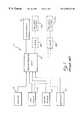
- FIG. 3illustrates a dental/medical work station according to the present invention
- FIG. 4is a schematic block diagram illustrating an electromagnetic cutter using conditioned fluid, according to one embodiment of the present invention.
- FIG. 5 aillustrates one embodiment of the electromagnetic cutter of FIG. 2
- FIG. 5 billustrates another embodiment of the electromagnetic cutter of FIG. 2;
- FIG. 6 aillustrates a mechanical drilling apparatus according to the present invention
- FIG. 6 billustrates a syringe according to the present invention
- FIG. 7illustrates the fluid conditioning system of the present invention
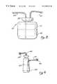
- FIG. 8illustrates one embodiment of the fluid conditioning unit of the present invention.
- FIG. 9illustrates the air conditioning unit of the present invention.
- the dental/medical work station 111 of the present inventionis shown in FIG. 3, with elements similar to those shown in FIG. 1 proceeded by a “1”.
- the dental/medical work station illcomprises a conventional air line 113 and a conventional water line 114 for supplying air and water, respectively.
- a vacuum line 112 and an electrical outlet 115supply negative air pressure and electricity to the dental/medical unit 116 , similarly to the vacuum 12 and electrical 15 lines shown in FIG. 1 .
- the fluid conditioning unit 121may, alternatively, be placed between the dental/medical unit 116 and the instruments 117 , for example.
- the air line 113 and the water line 114are both connected to a fluid conditioning unit 121 .
- a controller 125allows for user inputs, to control whether air from the air line 113 , water from the water line 114 , or both, are conditioned by the fluid conditioning unit 121 .
- a variety of agentsmay be applied to the air or water by the fluid conditioning unit 121 , according to a configuration of the controller 125 , for example, to thereby condition the air or water, before the air or water is output to the dental/medical unit 116 .
- Flavoring agents and related substancesfor example, may be used, such as disclosed in 21 C.F.R. Sections 172.510 and 172.515, the details of which are incorporated herein by reference. Colors, for example, may also be used for conditioning, such as disclosed in 21 C.F.R. Section 73.1 to Section 73.3126.
- the instruments 117may comprise an electrocauterizer, an electromagnetic energy source, a laser, a mechanical drill, a mechanical saw, a canal finder, a syringe, and/or an evacuator. All of these instruments 117 use air from the air line 113 and/or water from the water line 114 , which may or may not be conditioned depending on the configuration of the controller 125 . Any of the instruments 117 may alternatively be connected directly to the fluid conditioning unit 121 or directly to any of the air 113 , water 114 , vacuum 112 , and/or electric 115 lines.
- a laser 118 and delivery system 119is shown in phantom connected to the fluid conditioning unit 121 .
- the laser 118 a and delivery system 119 amay be connected to the dental/medical unit 116 , instead of being grouped with the instruments 117 .
- FIG. 4illustrates one embodiment of a laser 51 directly coupled with, for example, the air 113 , water 114 , and power 115 lines of FIG. 3.
- a separate fluid conditioning systemis used in this embodiment.
- any of these toolsmay instead, or additionally, be connected to the dental/medical unit 116 or the fluid conditioning unit 121 , or both.
- an electromagnetically induced mechanical cutteris used for cutting. Details of this cutter are disclosed in co-pending U.S. Pat. No. 5,741,247 assigned to the assignee of this application.
- the electromagnetic cutter energy source 51is connected directly to the outlet 115 (FIG. 3 ), and is coupled to both a controller 53 and a delivery system 55 .
- the delivery system 55routes and focuses the laser 51 .
- thermal cutting forcesare imparted onto the target 57 .
- the delivery system 55preferably comprises a fiberoptic guide for routing the laser 51 into an interaction zone 59 , located above the target surface 57 .
- the fluid router 60preferably comprises an atomizer for delivering user-specified combinations of atomized fluid particles into the interaction zone 59 .
- the atomized fluid particlesare conditioned, according to the present invention, and may comprise flavors, scents, saline, tooth-whitening agents and other agents, as discussed below.
- a stream or mist of conditioned fluidis supplied by the fluid router 60 .
- the controller 53may control various operating parameters of the laser 51 , the conditioning of the fluid from the fluid router 60 , and the specific characteristics of the fluid from the fluid router 60 .
- FIG. 5 ashows a simple embodiment of the electromagnetically induced mechanical cutter, in which a fiberoptic guide 61 , an air tube 63 , and a fluid tube 65 are placed within a hand-held housing 67 .
- the air tube 63 and water tube 65are preferably connected to either the fluid conditioning unit 121 or the dental/medical unit 116 of FIG. 3 .
- the fluid tube 65is preferably operated under a relatively low pressure, and the air tube 63 is preferably operated under a relatively high pressure.
- either the air from the air tube 63 or the fluid from the fluid tube 65 , or both,are selectively conditioned by the fluid conditioning unit 121 , as controlled by the controller 125 .
- the laser energy from the fiberoptic guide 61focuses onto a combination of air and fluid, from the air tube 63 and the fluid tube 65 , at the interaction zone 59 .
- Atomized fluid particles in the air and fluid mixtureabsorb energy from the laser energy of the fiberoptic tube 61 , and explode. The explosive forces from these atomized fluid particles impart mechanical cutting forces onto the target 57 .
- a conventional optical cutterfocuses laser energy on a target surface at an area A, for example, and the electromagnetically induced mechanical cutter focuses laser energy into an interaction zone B, for example.
- the conventional optical cutteruses the laser energy directly to cut tissue, and the electromagnetically induced mechanical cutter uses the laser energy to expand atomized fluid particles to thus impart mechanical cutting forces onto the target surface.
- the atomized fluid particlesare heated, expanded, and cooled before contacting the target surface.
- FIG. 5 billustrates a preferred embodiment of the electromagnetically induced mechanical cutter.
- the atomizer for generating atomized fluid particlescomprises a nozzle 71 , which may be interchanged with other nozzles (not shown) for obtaining various spatial distributions of the atomized fluid particles, according to the type of cut desired.
- a second nozzle 72shown in phantom lines, may also be used.
- a usercontrols the air and water pressure entering into the nozzle 71 .
- the nozzle 71is thus capable of generating many different user-specified combinations of atomized fluid particles and aerosolized sprays.
- Intense energyis emitted from the fiberoptic guide 23 .
- This intense energyis preferably generated from a coherent source, such as a laser.
- the lasercomprises an erbium, chromium, yttrium, scandium, gallium garnet (Er, Cr:YSGG) solid state laser.
- Er, Cr:YSGGscandium, gallium garnet
- laser systems of different wavelengthssuch as Neodymium yttrium aluminum garnet-Nd:YAG wavelengths may be selected to allow for high absorption by the fluid.
- the delivery system 55 for delivering the electromagnetic energyincludes a fiberoptic energy guide or equivalent which attaches to the laser system and travels to the desired work site.
- Fiberoptics or waveguidesare typically long, thin and lightweight, and are easily manipulated.
- Fiberopticscan be made of calcium fluoride (CaF), calcium oxide (Ca02), zirconium oxide (Zr02), zirconium fluoride (ZrF), sapphire, hollow waveguide, liquid core, TeX glass, quartz silica, germanium sulfide, arsenic sulfide, germanium oxide (Ge02), and other materials.
- Other delivery systemsinclude devices comprising mirrors, lenses and other optical components where the energy travels through a cavity, is directed by various mirrors, and is focused onto the targeted cutting site with specific lenses.
- the preferred embodiment of light delivery for medical applications of the present inventionis through a fiberoptic conductor, because of its light weight, lower cost, and ability to be packaged inside of a handpiece of familiar size and weight to the surgeon, dentist, or clinician.
- Non-fiberoptic systemsmay be used in both industrial applications and medical applications, as well.
- the nozzle 71is employed to create an engineered combination of small particles of the chosen fluid.
- the nozzle 71may comprise several different designs including liquid only, air blast, air assist, swirl, solid cone, etc. When fluid exits the nozzle 71 at a given pressure and rate, it is transformed into particles of user-controllable sizes, velocities, and spatial distributions.
- a mechanical drill 60is shown in FIG. 6 a, comprising a handle 62 , a drill bit 64 , and a water output 66 .
- the mechanical drill 60comprises a motor 68 , which may be electrically driven, or driven by pressurized air.
- the fluidenters the mechanical drill 60 through the first supply line 70 .
- Fluid entering through the first supply line 70passes through the motor 68 , which may comprise a turbine, for example, to thereby provide rotational forces to the drill bit 64 .
- a portion of the fluidwhich may not appeal to a patient's taste and/or smell, may exit around the drill bit 64 , coming into contact with the patient's mouth and/or nose. The majority of the fluid exits back through the first supply line 70 .
- the first supply line 70provides electric power.
- the second supply line 74supplies fluid to the fluid output 66 .
- the water and/or air supplied to the mechanical drill 60may be selectively conditioned by the fluid conditioning unit 121 , according to the configuration of the controller 125 .
- the syringe 76 shown in FIG. 6 bcomprises an air input line 78 and a water input line 80 .
- a user control 82is movable between a first position and a second position. The first position supplies air from the air line 78 to the output tip 84 , and the second position supplies water from the water line 80 to the output tip 84 . Either the air from the air line 78 , the water from the water line 80 , or both, may be selectively conditioned by the fluid conditioning unit 121 , according to the configuration of the controller 125 , for example.
- FIG. 7a portion of the fluid conditioning unit 121 (FIG. 3) is shown.
- This fluid conditioning unit 121is preferably adaptable to existing water lines 114 , for providing conditioned fluid to the dental/medical unit 116 as a substitute for regular tap water in drilling and cutting operations, for example.
- the interface 89connects to an existing water line 114 and feeds water through the fluid-in line 81 and the bypass line 91 .
- the reservoir 83accepts water from the fluid-in line 81 and outputs conditioned fluid to the fluid-out line 85 .
- the fluid-in line 81 , the reservoir 83 , and the fluid-out line 85together comprise a fluid conditioning subunit 87 .
- Conditioned fluidis output from the fluid conditioning subunit 87 into the combination unit 93 .
- the fluidmay be conditioned by conventional means, such as the addition of a tablet, liquid syrup, or a flavor cartridge.
- regular wateris also input into the combination unit 93 .
- a user input 95 into the controller 125determines whether fluid output from the combination unit 93 into the fluid tube 65 comprises only conditioned fluid from the fluidout line 85 , only regular water from the bypass line 91 , or a combination thereof.
- the user input 95comprises a rotatable knob, a pedal, or a foot switch, operable by a user, for determining the proportions of conditioned fluid and regular water. These proportions may be determined according to the pedal or knob position.
- a full-down pedal positioncorresponds to only conditioned fluid from the fluid outline 85 being output into the fluid tube 65
- a full pedal up positioncorresponds to only water from the bypass line 91 being output into the fluid tube 65
- the bypass line 91 , the combination unit 93 , and the user input 95provide versatility, but may be omitted, according to preference.
- a simple embodiment for conditioning fluidwould comprises only the fluid conditioning subunit 87 .
- FIG. 8An alternative embodiment of the fluid conditioning subunit 87 is shown in FIG. 8 .
- the fluid conditioning subunit 187inputs air from air line 113 via an air input line 181 , and outputs conditioned fluid via a fluid output line 185 .
- the fluid output line 185preferably extends vertically down into the reservoir 183 into the fluid 191 located therein.
- the lid 184may be removed and conditioned fluid inserted into the reservoir 183 .
- a solid or liquid form of fluid conditionermay be added to water already in the reservoir 183 .
- the fluidis preferably conditioned, using either a scent fluid drop or a scent tablet (not shown), and may be supplied with fungible cartridges, for example.
- the fluid 191 within the reservoir 183may be conditioned to achieve a desired flavor, such as a fruit flavor or a mint flavor, or may be conditioned to achieve a desired scent, such as an air freshening smell.
- a desired flavorsuch as a fruit flavor or a mint flavor
- a desired scentsuch as an air freshening smell
- the flavoring agent for achieving the desired flavordoes not consist solely of a combination of saline and water and does not consist solely of a combination of detergent and water.
- a conditioned fluid having a scent, a scented mist, or a scented source of airmay be particularly advantageous for implementation in connection with an air conditioning unit, as shown in FIG. 9 and discussed below.
- other conditioning agentsmay be selectively added to a conventional water line, mist line, or air line.
- an ionized solutionsuch as saline water, or a pigmented solution may be added, as discussed below.
- agentsmay be added to change the density, specific gravity, pH, temperature, or viscosity of water and/or air supplied to a drilling or cutting operation.
- These agentsmay include a tooth-whitening agent for whitening a tooth of a patient.
- the tooth-whitening agentmay comprise, for example, a peroxide, such as hydrogen peroxide, urea peroxide, or carbamide peroxide.
- the tooth-whitening agentmay have a viscosity on an order of 0.1 poise or less.
- Medicationssuch as antibiotics, steroids, anesthetics, anti-inflammatories, disinfectants, adrenaline, epinephrine, or astringents may be added to the water and/or air used in a drilling or cutting operation.
- the medicationdoes not consist solely of a combination of saline and water and does not consist soley of a combination of detergent and water.
- an astringentmay be applied to a surgical area, via the water line to reduce bleeding. Vitamins, herbs, or minerals may also be used for conditioning the air or water used in a cutting or drilling procedure.
- An anesthetic or anti-inflammatory applied to a surgical woundmay reduce discomfort to the patient or trauma to the wound, and an antibiotic or disinfectant may prevent infection to the wound.
- the air conditioning subunit shown in FIG. 9is connectible into an existing air line 113 , via interfaces 286 and 289 .
- Conventional airenters the conditioning subunit via the air input line 281 , and exits an air output line 285 .
- the air input line 281preferably extends vertically into the reservoir 283 into a fluid 291 within the reservoir 283 .
- the fluid 291is preferably conditioned, using either a scent fluid drop or a scent tablet (not shown).
- the fluid 291may be conditioned with other agents, as discussed above in the context of conditioning water.
- water in the water line 31 or air in the air line 32 of a conventional laser cutting system(FIG. 2) is conditioned.
- Either the fluid tube 65 or the air tube 63 (FIG. 5 a ) of the electromagnetically induced mechanical cutteris conditioned.
- the air and/or water of a dental drilling, irrigating, suction, or electrocautery systemmay also be conditioned.
- the type of conditioningmay effect the cutting power of an electromagnetic or an electromagnetically induced mechanical cutter.
- these various conditioning agentsfurther provide versatility and programmability to the type of cut resulting from the electromagnetic or electromagnetically induced mechanical cutter. For example, introduction of a saline solution will reduce the speed of cutting. Such a biocompatible saline solution may be used for delicate cutting operations or, alternatively, may be used with a higher laser-power setting to approximate the cutting power achievable with regular water.
- Pigmented fluidsmay also be used with the electromagnetic or the electromagnetically induced mechanical cutter, according to the present invention.
- the electromagnetic energy sourcemay be set for maximum absorption of atomized fluid particles having a certain pigmentation, for example. These pigmented atomized fluid particles may then be used to achieve the mechanical cutting.
- a second water or mist sourcemay be used in the cutting operation, but since this second water or mist is not pigmented, the interaction with the electromagnetic energy source is minimized. As just one example of many, this secondary mist or water source could be flavored.
- the atomized fluid particlesmay be unpigmented, and the electromagnetic or the electromagnetically induced energy source may be set to provide maximum energy absorption for these unpigmented atomized fluid particles.
- a secondary pigmented fluid or mistmay then be introduced into the surgical area, and this secondary mist or water would not interact significantly with the electromagnetic energy source.
- a single source of atomized fluid particlesmay be switchable between pigmentation and non-pigmentation, and the electromagnetic energy source may be set to be absorbed by one of the two pigment states to thereby provide a dimension of controllability as to exactly when cutting is achieved.
- the source of atomized fluid particlesmay comprise a tooth whitening agent that is adapted to whiten a tooth of a patient.
- the tooth-whitening agentmay comprise, for example, a peroxide, such as hydrogen peroxide, urea peroxide, or carbamide peroxide.
- the tooth-whitening agentmay have a viscosity on an order of 0.1 poise or less.
- the source of atomized fluid particlesis switchable by a switching device between a first configuration wherein the atomized fluid particles comprise the tooth-whitening agent and a second configuration wherein the atomized fluid particles do not comprise the tooth-whitening agent.
- the electromagnetic or electromagnetically induced energy sourcemay comprise, for example, a laser that is operable between an on condition and an off condition, independently of the configuration of the switching device.
- the lasercan be operated in either the on or off condition.
- Disinfectantmay be added to an air or water source in order to combat bacteria growth within the air and water lines, and on surfaces within a dental operating room.
- the air and water lines of the dental unit 116may be periodically flushed with a disinfectant selected by the controller 125 and supplied by the fluid conditioning unit 121 .
- An accessory tube disinfecting unit 123may accommodate disinfecting cartridges and perform standardized or preprogrammed periodic flushing operations.
- an appropriate disinfectantmay be used.
- the disinfectantmay be applied at the end of a dental procedure as a mouthwash, for example, or may be applied during a medical or dental procedure.
- the air and water used to cool the tissue being cut or drilled within the patient's mouth, for example,is often vaporized into the air to some degree.
- a conditioned disinfectant solutionwill also be vaporized with air or water, and condensate onto surfaces of the dental equipment within the dental operating room. Any bacteria growth on these moist surfaces is significantly attenuated, as a result of the disinfectant on the surfaces.
Landscapes
- Health & Medical Sciences (AREA)
- Life Sciences & Earth Sciences (AREA)
- Physics & Mathematics (AREA)
- Public Health (AREA)
- Animal Behavior & Ethology (AREA)
- General Health & Medical Sciences (AREA)
- Veterinary Medicine (AREA)
- Optics & Photonics (AREA)
- Engineering & Computer Science (AREA)
- Epidemiology (AREA)
- Dentistry (AREA)
- Surgery (AREA)
- Oral & Maxillofacial Surgery (AREA)
- Otolaryngology (AREA)
- Nuclear Medicine, Radiotherapy & Molecular Imaging (AREA)
- Biomedical Technology (AREA)
- Heart & Thoracic Surgery (AREA)
- Medical Informatics (AREA)
- Molecular Biology (AREA)
- Water Supply & Treatment (AREA)
- Electromagnetism (AREA)
- Plasma & Fusion (AREA)
- Mechanical Engineering (AREA)
- Dental Tools And Instruments Or Auxiliary Dental Instruments (AREA)
Abstract
Description
Claims (40)
Priority Applications (19)
| Application Number | Priority Date | Filing Date | Title |
|---|---|---|---|
| US09/256,697US6350123B1 (en) | 1995-08-31 | 1999-02-24 | Fluid conditioning system |
| US09/822,981US6567582B1 (en) | 1995-08-31 | 2001-03-30 | Fiber tip fluid output device |
| US09/997,550US6561803B1 (en) | 1995-08-31 | 2001-11-27 | Fluid conditioning system |
| US10/177,743US6744790B1 (en) | 1995-08-31 | 2002-06-21 | Device for reduction of thermal lensing |
| US10/404,683US7187822B2 (en) | 1995-08-31 | 2003-04-01 | Fiber tip fluid output device |
| US10/435,325US7320594B1 (en) | 1995-08-31 | 2003-05-09 | Fluid and laser system |
| US11/033,441US7620290B2 (en) | 1995-08-31 | 2005-01-10 | Modified-output fiber optic tips |
| US11/033,044US20050281887A1 (en) | 1995-08-31 | 2005-01-10 | Fluid conditioning system |
| US11/186,409US20070208328A1 (en) | 1995-08-31 | 2005-07-20 | Contra-angel rotating handpiece having tactile-feedback tip ferrule |
| US11/330,388US20060240381A1 (en) | 1995-08-31 | 2006-01-10 | Fluid conditioning system |
| PCT/US2006/000989WO2006074486A2 (en) | 1995-08-31 | 2006-01-10 | Fluid conditioning system |
| US11/644,155US7424199B2 (en) | 1995-08-31 | 2006-12-22 | Fiber tip fluid output device |
| US12/190,690US8023795B2 (en) | 1995-08-31 | 2008-08-13 | Fiber tip fluid output device |
| US12/245,743US8033825B2 (en) | 1995-08-31 | 2008-10-04 | Fluid and pulsed energy output system |
| US12/336,528US20090105707A1 (en) | 1995-08-31 | 2008-12-16 | Drill and flavored fluid particles combination |
| US12/368,276US20090143775A1 (en) | 1995-08-31 | 2009-02-09 | Medical laser having controlled-temperature and sterilized fluid output |
| US12/693,370US20100125291A1 (en) | 1995-08-31 | 2010-01-25 | Drill and flavored fluid particles combination |
| US12/785,762US20100233645A1 (en) | 1997-12-05 | 2010-05-24 | Efficient laser and fluid conditioning and cutting system |
| US13/016,827US20110129789A1 (en) | 1995-08-31 | 2011-01-28 | Drill and flavored fluid particles combination |
Applications Claiming Priority (6)
| Application Number | Priority Date | Filing Date | Title |
|---|---|---|---|
| US08/522,503US5741247A (en) | 1995-08-31 | 1995-08-31 | Atomized fluid particles for electromagnetically induced cutting |
| US08/575,775US5785521A (en) | 1995-08-31 | 1995-12-20 | Fluid conditioning system |
| US98551397A | 1997-12-05 | 1997-12-05 | |
| US99524197A | 1997-12-17 | 1997-12-17 | |
| US09/256,697US6350123B1 (en) | 1995-08-31 | 1999-02-24 | Fluid conditioning system |
| US10/435,325US7320594B1 (en) | 1995-08-31 | 2003-05-09 | Fluid and laser system |
Related Parent Applications (2)
| Application Number | Title | Priority Date | Filing Date |
|---|---|---|---|
| US98551397AContinuation-In-Part | 1995-08-31 | 1997-12-05 | |
| US99524197AContinuation-In-Part | 1995-08-31 | 1997-12-17 |
Related Child Applications (5)
| Application Number | Title | Priority Date | Filing Date |
|---|---|---|---|
| US09/469,571Continuation-In-PartUS6389193B1 (en) | 1995-08-31 | 1999-12-22 | Rotating handpiece |
| US09/822,981Continuation-In-PartUS6567582B1 (en) | 1995-08-31 | 2001-03-30 | Fiber tip fluid output device |
| US09/997,550ContinuationUS6561803B1 (en) | 1995-08-31 | 2001-11-27 | Fluid conditioning system |
| US10/435,325ContinuationUS7320594B1 (en) | 1995-08-31 | 2003-05-09 | Fluid and laser system |
| US11/644,155Continuation-In-PartUS7424199B2 (en) | 1995-08-31 | 2006-12-22 | Fiber tip fluid output device |
Publications (1)
| Publication Number | Publication Date |
|---|---|
| US6350123B1true US6350123B1 (en) | 2002-02-26 |
Family
ID=46276335
Family Applications (2)
| Application Number | Title | Priority Date | Filing Date |
|---|---|---|---|
| US09/256,697Expired - Fee RelatedUS6350123B1 (en) | 1995-08-31 | 1999-02-24 | Fluid conditioning system |
| US09/997,550Expired - Fee RelatedUS6561803B1 (en) | 1995-08-31 | 2001-11-27 | Fluid conditioning system |
Family Applications After (1)
| Application Number | Title | Priority Date | Filing Date |
|---|---|---|---|
| US09/997,550Expired - Fee RelatedUS6561803B1 (en) | 1995-08-31 | 2001-11-27 | Fluid conditioning system |
Country Status (1)
| Country | Link |
|---|---|
| US (2) | US6350123B1 (en) |
Cited By (62)
| Publication number | Priority date | Publication date | Assignee | Title |
|---|---|---|---|---|
| US6533803B2 (en)* | 2000-12-22 | 2003-03-18 | Advanced Medical Applications, Inc. | Wound treatment method and device with combination of ultrasound and laser energy |
| US6561803B1 (en)* | 1995-08-31 | 2003-05-13 | Bioluse Technology | Fluid conditioning system |
| US6620405B2 (en)* | 2001-11-01 | 2003-09-16 | 3M Innovative Properties Company | Delivery of hydrogel compositions as a fine mist |
| WO2004018144A1 (en)* | 2002-08-21 | 2004-03-04 | Koninklijke Philips Electronics N.V. | Method of breaking a brittle substrate |
| US20040092925A1 (en)* | 1995-08-31 | 2004-05-13 | Rizoiu Ioana M. | Methods of using atomized particles for electromagnetically induced cutting |
| US6758844B2 (en)* | 2002-01-24 | 2004-07-06 | Ceramoptec Industries, Inc. | System and method for oral treatments |
| US20040156743A1 (en)* | 2002-08-28 | 2004-08-12 | Eric Bornstein | Near infrared microbial elimination laser system |
| US20040170060A1 (en)* | 2003-02-27 | 2004-09-02 | Renesas Technology Corp. | Semiconductor storage device preventing data change due to accumulative disturbance |
| US20040246336A1 (en)* | 2003-06-04 | 2004-12-09 | Model Software Corporation | Video surveillance system |
| US6860879B2 (en)* | 1998-06-19 | 2005-03-01 | Karl Storz Gmbh & Co. Kg | Use of 5-aminolevulinic acid or a derivate thereof for photodynamic diagnosis and/or photodynamic therapy |
| US20050170310A1 (en)* | 2002-06-10 | 2005-08-04 | Olaf Schafer | Medical tools for dental treatments by means of a laser |
| WO2004086935A3 (en)* | 2003-04-01 | 2005-08-18 | B E D Laser Technologies Ltd | System, apparatus and method for large area tissue ablation |
| WO2005087317A1 (en)* | 2003-08-26 | 2005-09-22 | Eric Bornstein | Near infrared microbial elimination laser system |
| US20050281887A1 (en)* | 1995-08-31 | 2005-12-22 | Rizoiu Ioana M | Fluid conditioning system |
| US20060033963A1 (en)* | 2004-08-10 | 2006-02-16 | Hirobumi Nishida | Image processing device, image processing method, image processing program, and recording medium |
| US20060126680A1 (en)* | 2004-07-27 | 2006-06-15 | Dmitri Boutoussov | Dual pulse-width medical laser |
| US20060142745A1 (en)* | 2004-08-13 | 2006-06-29 | Dmitri Boutoussov | Dual pulse-width medical laser with presets |
| US20060240381A1 (en)* | 1995-08-31 | 2006-10-26 | Biolase Technology, Inc. | Fluid conditioning system |
| US20060241574A1 (en)* | 1995-08-31 | 2006-10-26 | Rizoiu Ioana M | Electromagnetic energy distributions for electromagnetically induced disruptive cutting |
| WO2006125204A2 (en) | 2005-05-18 | 2006-11-23 | Biolase Technology, Inc. | Electromagnetic radiation emitting toothbrush and dentifrice system |
| US20070014322A1 (en)* | 1995-08-31 | 2007-01-18 | Biolase Technology, Inc. | Electromagnetic energy distributions for electromagnetically induced mechanical cutting |
| US20070265604A1 (en)* | 2006-03-03 | 2007-11-15 | Davenport Scott A | Aesthetic treatment for wrinkle reduction and rejuvenation |
| US20080003540A1 (en)* | 2003-12-29 | 2008-01-03 | Fluorinex Active Ltd. | Electrochemically treating teeth |
| US7320594B1 (en)* | 1995-08-31 | 2008-01-22 | Biolase Technology, Inc. | Fluid and laser system |
| US20080032251A1 (en)* | 2006-07-19 | 2008-02-07 | Mau-Song Chou | Laser carious region ablation |
| US20080065057A1 (en)* | 2001-06-21 | 2008-03-13 | Biolase Technology, Inc. | High-efficiency, side-pumped diode laser system |
| US20080069172A1 (en)* | 2006-09-18 | 2008-03-20 | Rizoiu Ioana M | Electromagnetic energy distributions for electromagnetically induced mechanical cutting |
| US20080157690A1 (en)* | 2001-05-02 | 2008-07-03 | Biolase Technology, Inc. | Electromagnetic energy distributions for electromagnetically induced mechanical cutting |
| US20090105790A1 (en)* | 2002-08-28 | 2009-04-23 | Nomir Medical Technologies, Inc. | Near Infrared Microbial Elimination Laser Systems (NIMELS) |
| US20090141752A1 (en)* | 2004-07-27 | 2009-06-04 | Rizoiu Ioana M | Dual pulse-width medical laser with presets |
| US20090143775A1 (en)* | 1995-08-31 | 2009-06-04 | Rizoiu Ioana M | Medical laser having controlled-temperature and sterilized fluid output |
| US20090182397A1 (en)* | 2008-01-16 | 2009-07-16 | Candela Corporation | Fluorescent handpiece |
| US7677888B1 (en)* | 2005-07-05 | 2010-03-16 | Halm Gary V | Combination placement tool and light |
| US20100125291A1 (en)* | 1995-08-31 | 2010-05-20 | Rizoiu Ioana M | Drill and flavored fluid particles combination |
| WO2010062969A1 (en) | 2008-11-29 | 2010-06-03 | Biolase Technology, Inc. | Non-contact handpiece for laser tissue cutting |
| US20100151406A1 (en)* | 2004-01-08 | 2010-06-17 | Dmitri Boutoussov | Fluid conditioning system |
| US20100185188A1 (en)* | 1997-06-12 | 2010-07-22 | Dmitri Boutoussov | Electromagnetically induced treatment devices and methods |
| US20110129789A1 (en)* | 1995-08-31 | 2011-06-02 | Biolase Technology, Inc. | Drill and flavored fluid particles combination |
| CN101076294B (en)* | 2003-03-18 | 2011-08-17 | 塞拉莫普泰克工业公司 | Oral treatment system and device |
| USD648882S1 (en) | 2010-11-02 | 2011-11-15 | Halm Gary V | Combination light and IR detector |
| EP2457546A2 (en) | 2005-04-26 | 2012-05-30 | BioLase Technology, Inc. | Methods for treating eye conditions |
| DE202005022082U1 (en) | 2004-01-08 | 2013-03-14 | Biolase Inc. | Fiber optic tips with modified output |
| US8465532B2 (en) | 2008-01-16 | 2013-06-18 | Morgan Lars Ake Gustavsson | Fluorescent handpiece |
| EP2638876A2 (en) | 2004-08-13 | 2013-09-18 | Biolase, Inc. | Laser handpiece architecture and methods |
| US20140113243A1 (en)* | 2012-10-24 | 2014-04-24 | Biolase, Inc. | Handpiece Assembly for Laser Treatment Device |
| CN104921827A (en)* | 2015-06-19 | 2015-09-23 | 王强 | Oral cavity cleaner |
| US9155905B2 (en) | 2008-01-16 | 2015-10-13 | Morgan Lars Ake Gustavsson | Fluorescent handpiece |
| EP2937055A1 (en) | 2008-10-15 | 2015-10-28 | Biolase, Inc. | Satellite-platformed electromagnetic energy treatment device |
| US9622840B2 (en) | 2010-06-15 | 2017-04-18 | The Procter & Gamble Company | Methods for whitening teeth |
| EP3300683A1 (en)* | 2016-09-30 | 2018-04-04 | Ferton Holding S.A. | A conduit arrangement of a fluid distributor device and a method for cleaning a conduit arrangement of a fluid distributor device |
| US9956150B2 (en)* | 2016-03-11 | 2018-05-01 | John Irving White | Dental cutting lubricant and method of use thereof |
| US10130424B2 (en) | 2014-01-31 | 2018-11-20 | Biolase, Inc. | Multiple beam laser treatment device |
| USD849942S1 (en) | 2017-07-12 | 2019-05-28 | Colgate-Palmolive Company | Illuminated oral care device |
| USD849956S1 (en) | 2017-07-12 | 2019-05-28 | Colgate-Palmolive Company | Oral care device |
| EP3666209A2 (en) | 2010-11-04 | 2020-06-17 | Biolase, Inc. | Initiation sequences for ramping-up pulse power in a medical laser having high-intensity leading subpulses |
| US11684421B2 (en) | 2006-08-24 | 2023-06-27 | Pipstek, Llc | Dental and medical treatments and procedures |
| US11701202B2 (en) | 2013-06-26 | 2023-07-18 | Sonendo, Inc. | Apparatus and methods for filling teeth and root canals |
| USD997355S1 (en) | 2020-10-07 | 2023-08-29 | Sonendo, Inc. | Dental treatment instrument |
| US11918432B2 (en) | 2006-04-20 | 2024-03-05 | Sonendo, Inc. | Apparatus and methods for treating root canals of teeth |
| US12114924B2 (en) | 2006-08-24 | 2024-10-15 | Pipstek, Llc | Treatment system and method |
| US12186151B2 (en) | 2010-10-21 | 2025-01-07 | Sonendo, Inc. | Apparatus, methods, and compositions for endodontic treatments |
| US12268565B2 (en) | 2009-11-13 | 2025-04-08 | Sonendo, Inc. | Liquid jet apparatus and methods for dental treatments |
Families Citing this family (9)
| Publication number | Priority date | Publication date | Assignee | Title |
|---|---|---|---|---|
| US20070190482A1 (en)* | 2003-05-09 | 2007-08-16 | Rizoiu Ioana M | Fluid conditioning system |
| US20060142743A1 (en)* | 2004-07-27 | 2006-06-29 | Rizoiu Ioana M | Medical laser having controlled-temperature and sterilized fluid output |
| WO2006074486A2 (en)* | 1995-08-31 | 2006-07-13 | Biolase Technology, Inc. | Fluid conditioning system |
| US6669685B1 (en)* | 1997-11-06 | 2003-12-30 | Biolase Technology, Inc. | Tissue remover and method |
| US20090298004A1 (en)* | 1997-11-06 | 2009-12-03 | Rizoiu Ioana M | Tunnelling probe |
| US20050239019A1 (en)* | 2004-04-21 | 2005-10-27 | Hall Teena V | Method of applying an antiseptic to an oral appliance |
| EP1842076A4 (en)* | 2005-01-10 | 2014-11-26 | Biolase Inc | Fluid conditioning system |
| DE102005021261A1 (en)* | 2005-05-09 | 2006-11-16 | Teichert, Klaus, Dr. med. | Dental cleaning method and tooth cleaning device with ultrasound |
| WO2008005996A2 (en)* | 2006-07-05 | 2008-01-10 | Stryker Corporation | Medical/surgical lavage system capable of selectively and sequentially discharging either a base solution or a solution which includes a therapeutic agent |
Citations (9)
| Publication number | Priority date | Publication date | Assignee | Title |
|---|---|---|---|---|
| US4983381A (en)* | 1985-12-30 | 1991-01-08 | Futura Medical S.A. | Method and device for producing the whitening of live teeth with pathological and normal colorations |
| US5267856A (en)* | 1991-09-20 | 1993-12-07 | Premier Laser Systems, Inc. | Laser surgical method |
| US5275564A (en)* | 1988-08-25 | 1994-01-04 | American Dental Laser, Inc. | Dental laser assembly |
| US5658148A (en)* | 1995-04-26 | 1997-08-19 | Ceramoptec Industries, Inc. | Dental laser brushing or cleaning device |
| US5713738A (en)* | 1995-12-12 | 1998-02-03 | Britesmile, Inc. | Method for whitening teeth |
| US5741247A (en)* | 1995-08-31 | 1998-04-21 | Biolase Technology, Inc. | Atomized fluid particles for electromagnetically induced cutting |
| US5785521A (en)* | 1995-08-31 | 1998-07-28 | Biolase Technology, Inc. | Fluid conditioning system |
| US5800165A (en)* | 1995-03-28 | 1998-09-01 | Loma Linda University Medical Center | Dental instrument and method of bleaching teeth using a laser |
| US5879159A (en)* | 1996-12-24 | 1999-03-09 | Ion Laser Technology, Inc. | Portable high power arc lamp system and applications therefor |
Family Cites Families (1)
| Publication number | Priority date | Publication date | Assignee | Title |
|---|---|---|---|---|
| US6350123B1 (en)* | 1995-08-31 | 2002-02-26 | Biolase Technology, Inc. | Fluid conditioning system |
- 1999
- 1999-02-24USUS09/256,697patent/US6350123B1/ennot_activeExpired - Fee Related
- 2001
- 2001-11-27USUS09/997,550patent/US6561803B1/ennot_activeExpired - Fee Related
Patent Citations (9)
| Publication number | Priority date | Publication date | Assignee | Title |
|---|---|---|---|---|
| US4983381A (en)* | 1985-12-30 | 1991-01-08 | Futura Medical S.A. | Method and device for producing the whitening of live teeth with pathological and normal colorations |
| US5275564A (en)* | 1988-08-25 | 1994-01-04 | American Dental Laser, Inc. | Dental laser assembly |
| US5267856A (en)* | 1991-09-20 | 1993-12-07 | Premier Laser Systems, Inc. | Laser surgical method |
| US5800165A (en)* | 1995-03-28 | 1998-09-01 | Loma Linda University Medical Center | Dental instrument and method of bleaching teeth using a laser |
| US5658148A (en)* | 1995-04-26 | 1997-08-19 | Ceramoptec Industries, Inc. | Dental laser brushing or cleaning device |
| US5741247A (en)* | 1995-08-31 | 1998-04-21 | Biolase Technology, Inc. | Atomized fluid particles for electromagnetically induced cutting |
| US5785521A (en)* | 1995-08-31 | 1998-07-28 | Biolase Technology, Inc. | Fluid conditioning system |
| US5713738A (en)* | 1995-12-12 | 1998-02-03 | Britesmile, Inc. | Method for whitening teeth |
| US5879159A (en)* | 1996-12-24 | 1999-03-09 | Ion Laser Technology, Inc. | Portable high power arc lamp system and applications therefor |
Cited By (114)
| Publication number | Priority date | Publication date | Assignee | Title |
|---|---|---|---|---|
| US20080151953A1 (en)* | 1995-08-31 | 2008-06-26 | Biolase Technology, Inc. | Electromagnet energy distributions for electromagnetically induced mechanical cutting |
| US20070014322A1 (en)* | 1995-08-31 | 2007-01-18 | Biolase Technology, Inc. | Electromagnetic energy distributions for electromagnetically induced mechanical cutting |
| US6561803B1 (en)* | 1995-08-31 | 2003-05-13 | Bioluse Technology | Fluid conditioning system |
| US20100125291A1 (en)* | 1995-08-31 | 2010-05-20 | Rizoiu Ioana M | Drill and flavored fluid particles combination |
| US20040092925A1 (en)* | 1995-08-31 | 2004-05-13 | Rizoiu Ioana M. | Methods of using atomized particles for electromagnetically induced cutting |
| US20060240381A1 (en)* | 1995-08-31 | 2006-10-26 | Biolase Technology, Inc. | Fluid conditioning system |
| US20090143775A1 (en)* | 1995-08-31 | 2009-06-04 | Rizoiu Ioana M | Medical laser having controlled-temperature and sterilized fluid output |
| US8033825B2 (en) | 1995-08-31 | 2011-10-11 | Biolase Technology, Inc. | Fluid and pulsed energy output system |
| US7320594B1 (en)* | 1995-08-31 | 2008-01-22 | Biolase Technology, Inc. | Fluid and laser system |
| US20050281887A1 (en)* | 1995-08-31 | 2005-12-22 | Rizoiu Ioana M | Fluid conditioning system |
| US20110129789A1 (en)* | 1995-08-31 | 2011-06-02 | Biolase Technology, Inc. | Drill and flavored fluid particles combination |
| US20060241574A1 (en)* | 1995-08-31 | 2006-10-26 | Rizoiu Ioana M | Electromagnetic energy distributions for electromagnetically induced disruptive cutting |
| US7696466B2 (en) | 1995-08-31 | 2010-04-13 | Biolase Technology, Inc. | Electromagnetic energy distributions for electromagnetically induced mechanical cutting |
| US20100185188A1 (en)* | 1997-06-12 | 2010-07-22 | Dmitri Boutoussov | Electromagnetically induced treatment devices and methods |
| US6860879B2 (en)* | 1998-06-19 | 2005-03-01 | Karl Storz Gmbh & Co. Kg | Use of 5-aminolevulinic acid or a derivate thereof for photodynamic diagnosis and/or photodynamic therapy |
| US6533803B2 (en)* | 2000-12-22 | 2003-03-18 | Advanced Medical Applications, Inc. | Wound treatment method and device with combination of ultrasound and laser energy |
| US20080157690A1 (en)* | 2001-05-02 | 2008-07-03 | Biolase Technology, Inc. | Electromagnetic energy distributions for electromagnetically induced mechanical cutting |
| US20080065057A1 (en)* | 2001-06-21 | 2008-03-13 | Biolase Technology, Inc. | High-efficiency, side-pumped diode laser system |
| US6620405B2 (en)* | 2001-11-01 | 2003-09-16 | 3M Innovative Properties Company | Delivery of hydrogel compositions as a fine mist |
| WO2004082499A1 (en)* | 2002-01-24 | 2004-09-30 | Ceramoptec Industries, Inc. | System and method for oral treatments |
| US6758844B2 (en)* | 2002-01-24 | 2004-07-06 | Ceramoptec Industries, Inc. | System and method for oral treatments |
| US20050170310A1 (en)* | 2002-06-10 | 2005-08-04 | Olaf Schafer | Medical tools for dental treatments by means of a laser |
| US7632264B2 (en)* | 2002-06-10 | 2009-12-15 | Olaf Schafer | Medical tools for dental treatments by means of a laser |
| WO2004018144A1 (en)* | 2002-08-21 | 2004-03-04 | Koninklijke Philips Electronics N.V. | Method of breaking a brittle substrate |
| US7713294B2 (en) | 2002-08-28 | 2010-05-11 | Nomir Medical Technologies, Inc. | Near infrared microbial elimination laser systems (NIMEL) |
| US20040156743A1 (en)* | 2002-08-28 | 2004-08-12 | Eric Bornstein | Near infrared microbial elimination laser system |
| US8535359B2 (en) | 2002-08-28 | 2013-09-17 | Nomir Medical Technologies, Inc. | Near infrared microbial elimination laser systems (NIMELS) |
| US20090105790A1 (en)* | 2002-08-28 | 2009-04-23 | Nomir Medical Technologies, Inc. | Near Infrared Microbial Elimination Laser Systems (NIMELS) |
| US20040170060A1 (en)* | 2003-02-27 | 2004-09-02 | Renesas Technology Corp. | Semiconductor storage device preventing data change due to accumulative disturbance |
| CN101076294B (en)* | 2003-03-18 | 2011-08-17 | 塞拉莫普泰克工业公司 | Oral treatment system and device |
| WO2004086935A3 (en)* | 2003-04-01 | 2005-08-18 | B E D Laser Technologies Ltd | System, apparatus and method for large area tissue ablation |
| US20060189965A1 (en)* | 2003-04-01 | 2006-08-24 | Emil Litvak | System,apparatus and method for large area tissue ablation |
| US20080138764A1 (en)* | 2003-05-09 | 2008-06-12 | Rizoiu Ioana M | Fluid and laser system |
| US20040246336A1 (en)* | 2003-06-04 | 2004-12-09 | Model Software Corporation | Video surveillance system |
| WO2005087317A1 (en)* | 2003-08-26 | 2005-09-22 | Eric Bornstein | Near infrared microbial elimination laser system |
| CN100588439C (en)* | 2003-08-26 | 2010-02-10 | 诺米尔医疗技术公司 | Near infrared microbial elimination laser system |
| US7775795B2 (en)* | 2003-12-29 | 2010-08-17 | Fluorinex Active Ltd. | Electrochemically treating teeth |
| US20080003540A1 (en)* | 2003-12-29 | 2008-01-03 | Fluorinex Active Ltd. | Electrochemically treating teeth |
| US20100151406A1 (en)* | 2004-01-08 | 2010-06-17 | Dmitri Boutoussov | Fluid conditioning system |
| DE202005022082U1 (en) | 2004-01-08 | 2013-03-14 | Biolase Inc. | Fiber optic tips with modified output |
| EP2329785A1 (en) | 2004-01-22 | 2011-06-08 | BioLase Technology, Inc. | Electromagnetically induced treatment devices |
| US7970030B2 (en) | 2004-07-27 | 2011-06-28 | Biolase Technology, Inc. | Dual pulse-width medical laser with presets |
| US7957440B2 (en) | 2004-07-27 | 2011-06-07 | Biolase Technology, Inc. | Dual pulse-width medical laser |
| US7630420B2 (en) | 2004-07-27 | 2009-12-08 | Biolase Technology, Inc. | Dual pulse-width medical laser |
| US20060126680A1 (en)* | 2004-07-27 | 2006-06-15 | Dmitri Boutoussov | Dual pulse-width medical laser |
| US20090141752A1 (en)* | 2004-07-27 | 2009-06-04 | Rizoiu Ioana M | Dual pulse-width medical laser with presets |
| US20080212624A1 (en)* | 2004-07-27 | 2008-09-04 | Biolase Technology, Inc. | Dual pulse-width medical laser |
| US20060033963A1 (en)* | 2004-08-10 | 2006-02-16 | Hirobumi Nishida | Image processing device, image processing method, image processing program, and recording medium |
| EP2638876A2 (en) | 2004-08-13 | 2013-09-18 | Biolase, Inc. | Laser handpiece architecture and methods |
| EP2438879A2 (en) | 2004-08-13 | 2012-04-11 | BioLase Technology, Inc. | Dual pulse-width medical laser with presets |
| EP3883072A1 (en) | 2004-08-13 | 2021-09-22 | Biolase, Inc. | Dual pulse-width medical laser with presets |
| US20060142745A1 (en)* | 2004-08-13 | 2006-06-29 | Dmitri Boutoussov | Dual pulse-width medical laser with presets |
| EP2974686A1 (en) | 2004-08-13 | 2016-01-20 | Biolase, Inc. | Dual pulse-width medical laser with presets |
| EP2457546A2 (en) | 2005-04-26 | 2012-05-30 | BioLase Technology, Inc. | Methods for treating eye conditions |
| WO2006125204A2 (en) | 2005-05-18 | 2006-11-23 | Biolase Technology, Inc. | Electromagnetic radiation emitting toothbrush and dentifrice system |
| US7677888B1 (en)* | 2005-07-05 | 2010-03-16 | Halm Gary V | Combination placement tool and light |
| US8656931B2 (en) | 2006-03-03 | 2014-02-25 | Cutera, Inc. | Aesthetic treatment for wrinkle reduction and rejuvenation |
| US7814915B2 (en) | 2006-03-03 | 2010-10-19 | Cutera, Inc. | Aesthetic treatment for wrinkle reduction and rejuvenation |
| US8276592B2 (en) | 2006-03-03 | 2012-10-02 | Cutera, Inc. | Aesthetic treatment for wrinkle reduction and rejuvenation |
| US20110004200A1 (en)* | 2006-03-03 | 2011-01-06 | Cutera, Inc. | Aesthetic treatment for wrinkle reduction and rejuvenation |
| US20070265604A1 (en)* | 2006-03-03 | 2007-11-15 | Davenport Scott A | Aesthetic treatment for wrinkle reduction and rejuvenation |
| US11918432B2 (en) | 2006-04-20 | 2024-03-05 | Sonendo, Inc. | Apparatus and methods for treating root canals of teeth |
| US20080032251A1 (en)* | 2006-07-19 | 2008-02-07 | Mau-Song Chou | Laser carious region ablation |
| US11684421B2 (en) | 2006-08-24 | 2023-06-27 | Pipstek, Llc | Dental and medical treatments and procedures |
| US12114924B2 (en) | 2006-08-24 | 2024-10-15 | Pipstek, Llc | Treatment system and method |
| US12213731B2 (en) | 2006-08-24 | 2025-02-04 | Pipstek, Llc | Dental and medical treatments and procedures |
| US20080069172A1 (en)* | 2006-09-18 | 2008-03-20 | Rizoiu Ioana M | Electromagnetic energy distributions for electromagnetically induced mechanical cutting |
| US7415050B2 (en) | 2006-09-18 | 2008-08-19 | Biolase Technology, Inc. | Electromagnetic energy distributions for electromagnetically induced mechanical cutting |
| US8287578B2 (en) | 2008-01-16 | 2012-10-16 | Morgan Lars Ake Gustavsson | Fluorescent handpiece |
| US8465532B2 (en) | 2008-01-16 | 2013-06-18 | Morgan Lars Ake Gustavsson | Fluorescent handpiece |
| US8518093B2 (en) | 2008-01-16 | 2013-08-27 | Morgan Lars Ake Gustavsson | Fluorescent handpiece |
| US20090182397A1 (en)* | 2008-01-16 | 2009-07-16 | Candela Corporation | Fluorescent handpiece |
| US9452298B2 (en) | 2008-01-16 | 2016-09-27 | Morgan Gustavsson | Fluorescent handpiece |
| US8579951B2 (en) | 2008-01-16 | 2013-11-12 | Morgan Gustavsson | Fluorescent handpiece |
| US8419781B2 (en) | 2008-01-16 | 2013-04-16 | Morgan Gustavsson | Fluorescent handpiece |
| US8105369B2 (en) | 2008-01-16 | 2012-01-31 | Morgan Gustavsson | Fluorescent handpiece |
| US8945105B2 (en) | 2008-01-16 | 2015-02-03 | Morgan Gustavsson | Fluorescent handpiece |
| US9539440B2 (en) | 2008-01-16 | 2017-01-10 | Gustavsson Nevada Holding Llc | Fluorescent handpiece |
| US9155905B2 (en) | 2008-01-16 | 2015-10-13 | Morgan Lars Ake Gustavsson | Fluorescent handpiece |
| US20110238047A1 (en)* | 2008-01-16 | 2011-09-29 | Morgan Lars Ake Gustavsson | Fluorescent handpiece |
| US9192779B2 (en) | 2008-01-16 | 2015-11-24 | Morgan Lars Ake Gustavsson | Fluorescent handpiece |
| US7955367B2 (en)* | 2008-01-16 | 2011-06-07 | Morgan Gustavsson | Fluorescent handpiece |
| EP2937055A1 (en) | 2008-10-15 | 2015-10-28 | Biolase, Inc. | Satellite-platformed electromagnetic energy treatment device |
| WO2010062969A1 (en) | 2008-11-29 | 2010-06-03 | Biolase Technology, Inc. | Non-contact handpiece for laser tissue cutting |
| EP3231385A1 (en) | 2008-11-29 | 2017-10-18 | Biolase, Inc. | Laser cutting device with an emission tip for contactless use |
| US12268565B2 (en) | 2009-11-13 | 2025-04-08 | Sonendo, Inc. | Liquid jet apparatus and methods for dental treatments |
| US20120136383A1 (en)* | 2009-12-04 | 2012-05-31 | Biolase Technology, Inc. | Fluid controller |
| US8485818B2 (en)* | 2009-12-04 | 2013-07-16 | Biolase, Inc. | Fluid controller |
| US9622840B2 (en) | 2010-06-15 | 2017-04-18 | The Procter & Gamble Company | Methods for whitening teeth |
| US9642687B2 (en) | 2010-06-15 | 2017-05-09 | The Procter & Gamble Company | Methods for whitening teeth |
| US11793620B2 (en) | 2010-06-15 | 2023-10-24 | The Procter & Gamble Company | Methods for whitening teeth |
| US12376951B2 (en) | 2010-06-15 | 2025-08-05 | The Procter & Gamble Company | Methods for whitening teeth |
| US10667893B2 (en) | 2010-06-15 | 2020-06-02 | The Procter & Gamble Company | Methods for whitening teeth |
| US12186151B2 (en) | 2010-10-21 | 2025-01-07 | Sonendo, Inc. | Apparatus, methods, and compositions for endodontic treatments |
| USD648882S1 (en) | 2010-11-02 | 2011-11-15 | Halm Gary V | Combination light and IR detector |
| EP3666209A2 (en) | 2010-11-04 | 2020-06-17 | Biolase, Inc. | Initiation sequences for ramping-up pulse power in a medical laser having high-intensity leading subpulses |
| US20140113243A1 (en)* | 2012-10-24 | 2014-04-24 | Biolase, Inc. | Handpiece Assembly for Laser Treatment Device |
| US9867997B2 (en)* | 2012-10-24 | 2018-01-16 | Biolase, Inc. | Handpiece assembly for laser treatment device |
| US11701202B2 (en) | 2013-06-26 | 2023-07-18 | Sonendo, Inc. | Apparatus and methods for filling teeth and root canals |
| US11103309B2 (en) | 2014-01-31 | 2021-08-31 | Biolase, Inc. | Multiple beam laser treatment device |
| US10130424B2 (en) | 2014-01-31 | 2018-11-20 | Biolase, Inc. | Multiple beam laser treatment device |
| CN104921827A (en)* | 2015-06-19 | 2015-09-23 | 王强 | Oral cavity cleaner |
| US9956150B2 (en)* | 2016-03-11 | 2018-05-01 | John Irving White | Dental cutting lubricant and method of use thereof |
| EP3708109A1 (en)* | 2016-09-30 | 2020-09-16 | Ferton Holding S.A. | A conduit arrangement of a fluid distributor and a method for cleaning a conduit arrangement of a fluid distributor device |
| EP3300683A1 (en)* | 2016-09-30 | 2018-04-04 | Ferton Holding S.A. | A conduit arrangement of a fluid distributor device and a method for cleaning a conduit arrangement of a fluid distributor device |
| USD912825S1 (en) | 2017-07-12 | 2021-03-09 | Colgate-Palmolive Company | Illuminated oral care device |
| USD1001290S1 (en) | 2017-07-12 | 2023-10-10 | Colgate-Palmolive Company | Oral care device |
| USD1045091S1 (en) | 2017-07-12 | 2024-10-01 | Colgate-Palmolive Company | Oral care device |
| USD940328S1 (en) | 2017-07-12 | 2022-01-04 | Colgate-Palmolive Company | Oral care device |
| USD935029S1 (en) | 2017-07-12 | 2021-11-02 | Colgate-Palmolive Company | Illuminated oral care device |
| USD908890S1 (en) | 2017-07-12 | 2021-01-26 | Colgate-Palmolive Company | Oral care device |
| USD849956S1 (en) | 2017-07-12 | 2019-05-28 | Colgate-Palmolive Company | Oral care device |
| USD849942S1 (en) | 2017-07-12 | 2019-05-28 | Colgate-Palmolive Company | Illuminated oral care device |
| USD997355S1 (en) | 2020-10-07 | 2023-08-29 | Sonendo, Inc. | Dental treatment instrument |
Also Published As
| Publication number | Publication date |
|---|---|
| US6561803B1 (en) | 2003-05-13 |
Similar Documents
| Publication | Publication Date | Title |
|---|---|---|
| US6350123B1 (en) | Fluid conditioning system | |
| US7320594B1 (en) | Fluid and laser system | |
| US5785521A (en) | Fluid conditioning system | |
| US20070190482A1 (en) | Fluid conditioning system | |
| EP0847319B1 (en) | User programmable combination of atomized particles for electromagnetically induced cutting | |
| EP2506792B1 (en) | Fluid controller | |
| US8033825B2 (en) | Fluid and pulsed energy output system | |
| US6744790B1 (en) | Device for reduction of thermal lensing | |
| US5741247A (en) | Atomized fluid particles for electromagnetically induced cutting | |
| US6254597B1 (en) | Tissue remover and method | |
| EP1748743B1 (en) | Electromagnetically induced treatment devices | |
| US20090298004A1 (en) | Tunnelling probe | |
| US20100125291A1 (en) | Drill and flavored fluid particles combination | |
| US20050281887A1 (en) | Fluid conditioning system | |
| CA2586117C (en) | User programmable combination of atomized particles for electromagnetically induced cutting | |
| WO2006074486A2 (en) | Fluid conditioning system | |
| EP0626229A1 (en) | Solid state laser for removing physiologic tissue | |
| EP1842076A2 (en) | Fluid conditioning system |
Legal Events
| Date | Code | Title | Description |
|---|---|---|---|
| AS | Assignment | Owner name:BIOLASE TECHNOLOGY, INC., CALIFORNIA Free format text:ASSIGNMENT OF ASSIGNORS INTEREST;ASSIGNORS:RIZOIU, IOANA M.;KIMMEL, ANDREW I.;REEL/FRAME:009939/0637;SIGNING DATES FROM 19990324 TO 19990326 | |
| CC | Certificate of correction | ||
| FPAY | Fee payment | Year of fee payment:4 | |
| FPAY | Fee payment | Year of fee payment:8 | |
| AS | Assignment | Owner name:MIDCAP FINANCIAL, LLC, AS AGENT AND AS A LENDER, M Free format text:SECURITY AGREEMENT;ASSIGNOR:BIOLASE TECHNOLOGY, INC.;REEL/FRAME:024900/0550 Effective date:20100527 | |
| AS | Assignment | Owner name:HENRY SCHEIN, INC., NEW YORK Free format text:SECURITY AGREEMENT;ASSIGNORS:BIOLASE TECHNOLOGY, INC.;BL ACQUISITION CORP.;BL ACQUISITION II INC.;REEL/FRAME:025066/0488 Effective date:20100923 | |
| AS | Assignment | Owner name:BIOLASE TECHNOLOGY, INC., CALIFORNIA Free format text:SECURITY AGREEMENT PAYOFF;ASSIGNOR:MIDCAP FINANCIAL, LLC, AGENT AND AS LENDER;REEL/FRAME:026285/0666 Effective date:20110208 | |
| AS | Assignment | Owner name:BL ACQUISTION CORP., CALIFORNIA Free format text:RELEASE BY SECURED PARTY;ASSIGNOR:HENRY SCHEIN, INC.;REEL/FRAME:028184/0218 Effective date:20120412 Owner name:BL ACQUISITION II INC., CALIFORNIA Free format text:RELEASE BY SECURED PARTY;ASSIGNOR:HENRY SCHEIN, INC.;REEL/FRAME:028184/0218 Effective date:20120412 Owner name:BIOLASE TECHNOLOGY, INC., CALIFORNIA Free format text:RELEASE BY SECURED PARTY;ASSIGNOR:HENRY SCHEIN, INC.;REEL/FRAME:028184/0218 Effective date:20120412 | |
| AS | Assignment | Owner name:BIOLASE, INC., CALIFORNIA Free format text:CHANGE OF NAME;ASSIGNOR:BIOLASE TECHNOLOGY, INC.;REEL/FRAME:029328/0096 Effective date:20120511 | |
| REMI | Maintenance fee reminder mailed | ||
| LAPS | Lapse for failure to pay maintenance fees | ||
| STCH | Information on status: patent discontinuation | Free format text:PATENT EXPIRED DUE TO NONPAYMENT OF MAINTENANCE FEES UNDER 37 CFR 1.362 | |
| FP | Lapsed due to failure to pay maintenance fee | Effective date:20140226 | |
| AS | Assignment | Owner name:PACIFIC MERCANTILE BANK, CALIFORNIA Free format text:SECURITY INTEREST;ASSIGNOR:BIOLASE, INC.;REEL/FRAME:050879/0223 Effective date:20191028 |