US6349913B1 - Cup holder having a vertically oriented drawer - Google Patents
Cup holder having a vertically oriented drawerDownload PDFInfo
- Publication number
- US6349913B1 US6349913B1US09/684,709US68470900AUS6349913B1US 6349913 B1US6349913 B1US 6349913B1US 68470900 AUS68470900 AUS 68470900AUS 6349913 B1US6349913 B1US 6349913B1
- Authority
- US
- United States
- Prior art keywords
- drawer
- stabilizing
- holding assembly
- slots
- set forth
- Prior art date
- Legal status (The legal status is an assumption and is not a legal conclusion. Google has not performed a legal analysis and makes no representation as to the accuracy of the status listed.)
- Expired - Fee Related
Links
- 230000000087stabilizing effectEffects0.000claimsabstractdescription65
- 235000013361beverageNutrition0.000description2
- 230000033001locomotionEffects0.000description2
- 230000002452interceptive effectEffects0.000description1
- 238000012986modificationMethods0.000description1
- 230000004048modificationEffects0.000description1
- 230000000414obstructive effectEffects0.000description1
Images


Classifications
- B—PERFORMING OPERATIONS; TRANSPORTING
- B60—VEHICLES IN GENERAL
- B60N—SEATS SPECIALLY ADAPTED FOR VEHICLES; VEHICLE PASSENGER ACCOMMODATION NOT OTHERWISE PROVIDED FOR
- B60N3/00—Arrangements or adaptations of other passenger fittings, not otherwise provided for
- B60N3/10—Arrangements or adaptations of other passenger fittings, not otherwise provided for of receptacles for food or beverages, e.g. refrigerated
- B60N3/102—Arrangements or adaptations of other passenger fittings, not otherwise provided for of receptacles for food or beverages, e.g. refrigerated storable or foldable in a non-use position
- B—PERFORMING OPERATIONS; TRANSPORTING
- B60—VEHICLES IN GENERAL
- B60N—SEATS SPECIALLY ADAPTED FOR VEHICLES; VEHICLE PASSENGER ACCOMMODATION NOT OTHERWISE PROVIDED FOR
- B60N3/00—Arrangements or adaptations of other passenger fittings, not otherwise provided for
- B60N3/10—Arrangements or adaptations of other passenger fittings, not otherwise provided for of receptacles for food or beverages, e.g. refrigerated
- B60N3/105—Arrangements or adaptations of other passenger fittings, not otherwise provided for of receptacles for food or beverages, e.g. refrigerated for receptables of different size or shape
- B60N3/108—Arrangements or adaptations of other passenger fittings, not otherwise provided for of receptacles for food or beverages, e.g. refrigerated for receptables of different size or shape with resilient holding elements
Definitions
- the inventionrelates to a beverage container holder. More specifically, the invention relates to cup holders which are designed for confined spaces for use in a passenger compartment of the motor vehicle.
- cup holdersBeverage container holders, commonly referred to as cup holders, are well-known in the motor vehicle arts. Many different types of such cup holders exist which can be mounted in various locations within the passenger compartment of the motor vehicle. These cup holders are typically movable between a stored or retracted position within a housing and an extended or use position removed from the housing.
- the cup holderhas a support member that acts as a drawer which pivots between a retracted position within its housing and an extended position outside of its housing.
- a container holder or stabilizing armrotates about its axis when it is released from the housing and pivots perpendicularly to the support member so that a cup may be held therein. Because the container holder rotates about its axis directly above the support member, this cup holder can only hold one cup or container at a time. This design is less desirable when multiple cups are needed to be stored.
- U.S. Pat. No. 5,762,307issued to Patmore on Jun. 9, 1998, discloses a cup holder capable of holding two cups side by side at a single time.
- the cup holderincludes a housing from which the cup holder pivots.
- the cup holderhas a support structure and a stabilizing structure.
- the support structure and stabilizing structurepivot through the same space to reach the use or extended position.
- This designis rugged and capable of holding more than one cup at a time.
- This designfails, however, to provide a cup holder which may be stored in a compact manner where access to the cup holder and storage space of the cup holder are limited.
- the cup holderhas a center structure from which the stabilizing arms and supports depend and extend therefrom.
- the center structurerequires a great deal of space to operate. This prevents the cup holder from being secured and stored in places having little space to provide an opening for the release of the cup holder into its extended or use position. Further, the space required to allow this cup holder to pivot from its retracted position to its extended position is great. Therefore, there is a need in the art for a cup holder capable of holding more than one cup at a time while having a small footprint allowing it to be stored in and accessed from a small location.
- a container holding assemblyincluding a housing defining an elongated vertical axis opening.
- a draweris movable between a retracted position within the housing and an extended position outside of the housing.
- the container holding assemblyalso includes a support platform pivotally secured to the drawer. The support platform pivots between a non-supporting position when the drawer is in the retracted position and a supporting position when the drawer is in the extended position.
- the container holding assemblyalso includes a stabilizing arm pivotally secured to the drawer.
- the stabilizing armincludes an inner surface defining an aperture. The stabilizing arm is pivotal between a non-stabilizing position when the drawer is in the retracted position and a stabilizing position when the drawer is in the extended position.
- the support platform and stabilizing armare designed such that the support platform travels through a portion of the aperture when the support platform pivots to and from the supporting position.
- FIG. 1is a perspective view of one embodiment of the invention, in an extended position, located in a passenger compartment, partially cut away, of a motor vehicle;
- FIG. 2is a top view of one embodiment of the invention in the extended position
- FIG. 3is a perspective view of one embodiment of the invention in the extended position
- FIG. 4is a perspective back view of one embodiment of the invention without a housing
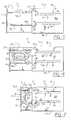
- FIG. 5is a side view of one embodiment of the invention in the extended position
- FIG. 6is a side view of one embodiment of the invention as the drawer is moving from the extended position toward a retracted position;
- FIG. 7is a side view of one embodiment of the invention as the drawer has moved substantially toward the retracted position.
- the inventionis a container or cup holder 10 .
- the cup holder 10includes a housing 12 .
- the housing 12is rectangular in shape.
- the housing 12also includes an opening 14 .
- the housing 12is securable to a structure 16 found inside a passenger compartment 18 of a motor vehicle 20 in any suitable manner.
- the structure 16is an instrument panel. It may be appreciated by those skilled in the art that the structure 16 may be any surface found in the passenger compartment 18 suitable for having a cup holder 10 stored therein.
- cup holder 10there are structures 16 within the passenger compartment 18 which are desirable for securing a cup holder 10 . Some of these locations are, however, compact and provide limited space for storage. The location of the cup holder 10 in the instrument panel 16 as shown in FIG. 1 is one of these locations. Further, these locations may include other objects, i.e., a steering wheel 22 , which may prevent the cup holder 10 from opening by obstructing or occupying the space immediately adjacent the structure 16 .
- a steering wheel 22may prevent the cup holder 10 from opening by obstructing or occupying the space immediately adjacent the structure 16 .
- the opening 14 of the housing 12is an elongated vertical axis opening 14 .
- the opening 14similar to the housing 12 , allows the cup holder 10 to be placed in a location with limited access available.
- the cup holder 10includes a drawer 24 .
- the drawer 24has a front face 26 which closes the vertical axis opening 14 to the housing when the drawer 24 is in its retracted or closed position.
- the front face 26is decorative and may take any shape or contour.
- the drawer 24is movable between a retracted position within the housing 12 and an extended position outside of the housing 12 .
- the drawer 24is in the extended position in FIGS. 1 through 6.
- the cup holder 10may hold two containers or cups (not shown).
- FIG. 7shows the drawer 24 approaching the retracted position.
- At least one support platform 28is pivotally secured to the drawer 24 .
- the support platforms 28 , 30extend between a base end 32 , 34 and the distal end 36 , 38 , respectively.
- the support platforms 28 , 30support the cups when they are being held by the cup holder 10 .
- Each of the support platforms 28 , 30includes a cut out 40 disclosed adjacent the distal ends 36 , 38 thereof.
- the support platforms 28 , 30pivot about the base ends 32 , 34 between a non-supporting position and a supporting position.
- the base ends 32 , 34are each connected to a rod 42 , 44 .
- the rods 42 , 44extend between the front face 26 and through a back plate 46 of the drawer 24 .
- Receptacles 47(one shown in FIGS. 5 through 7) are fixedly secured to the front face 26 to hold the front ends of the rods 42 , 44 thereto.
- Each of the rods 42 , 44include a support pin 48 , 50 .
- the support pins 48 , 50extend out perpendicularly to the longitudinal axis defined by the rods 42 , 44 .
- the orientation of the support pins 48 , 50is forty five degrees (45°) below that of the support platforms 28 , 30 to which their respective rods 42 , 44 are attached. More specifically, with regard to the support platform 28 , the support pin 48 extends out forty five degrees (45°) clockwise with respect to the support platform 28 and the support pin 50 extends out forty five degrees (45°) counterclockwise with respect to the support platform 30 as viewed from FIG. 4 .
- Each of the support pins 48 , 50include a rounded end 52 , 54 , respectively.
- the cup holder 10also includes at least one stabilizing arm 56 .
- the cup holder 10also includes at least one stabilizing arm 56 .
- two stabilizing arms 56 , 58are shown.
- Each of the stabilizing arms 56 , 58include flexible receiving tabs 60 used for receiving a cup therein and preventing the cup from moving and vibrating too much due to the size of the cup and vibrations found in the passenger compartment 18 of the motor vehicle 20 , respectively.
- the stabilizing arms 56 , 58hold the cup being supported by the support platforms 28 , 30 .
- the stabilizing arms 56 , 58are secured to rods 62 , 64 .
- the rods 62 , 64extend between the front face 26 and through the back plate 46 of the drawer 24 .
- Receptacles 66one shown in FIGS.
- each of the rods 62 , 64include a stabilizing pin 68 , 70 extending out therefrom perpendicularly to a longitudinal axis defined by the rods 62 , 64 .
- the stabilizing pins 68 , 70are offset from the stabilizing arms 56 , 58 by forty five degrees (45°). More specifically, the stabilizing pin 68 is forty five degrees (45°) counterclockwise with respect to the stabilizing arm 56 and the stabilizing pin 70 is forty five degrees (45°) clockwise with respect to the stabilizing arm 58 when viewed in FIG. 4 .
- the support pins 48 , 50 and the stabilizing pins 68 , 70are offset from each other by ninety degrees (90°) for each of their respective sides. This is best shown in FIG. 4 .
- the stabilizing pins 68 , 70each include a rounded end 72 , 74 .
- Each of the stabilizing arms 56 , 58define an inner surface 76 , 78 .
- the inner surfaces 76 , 78define an aperture 80 , 82 .
- the stabilizing arms 56 , 58are movable between a non-stabilizing position (FIG. 7) when the drawer 24 is in the retracted position and a stabilizing position (FIG. 5) when the drawer 24 is in the extended position.
- the support positions and non-support positions for the support platforms 28 , 30 and the stabilizing positions and the non-stabilizing positions for the stabilizing armsmay collectively be referred to as the “use positions” and “non-use positions,” respectively.
- a portion of the support platforms 28 , 30travel through a portion of the apertures 80 , 82 , respectively, when the support platforms 28 , 30 pivot to and from the supporting position, shown in FIG. 5 . Therefore, when the drawer 24 is moved from its retracted position to its extended position, the support platforms 28 , 30 pivot downwardly from the non-supporting position to the supporting positions and the stabilizing arms 56 , 58 pivot upwardly from the non-stabilizing positions to the stabilizing positions at the same time.
- the support platforms 28 , 30must pivot through a portion of the apertures 80 , 82 of the stabilizing arms 56 , 58 to prevent the support platforms 28 , 30 and the stabilizing arms 56 , 58 from interfering or colliding due to their respective pivoting motions.
- the support platforms 28 , 30extend through a portion of the apertures 80 , 82 , the longitudinal length of the drawer 24 can be reduced, further allowing the cup holder 10 to be located in confined spaces.
- the housing 12includes a top surface 84 , a bottom surface 86 and at least two vertical side walls 88 , 90 .
- Each of the vertical side walls 88 , 90includes two slots, generally shown at 92 , 94 (only one set of slots 92 , 94 are shown).
- Each of the slots 92 , 94receive a rounded end 54 , 74 from the support pin 48 and stabilizing pin 68 .
- the two slots 92 , 94mirror each other when viewed from an axis extending therebetween.
- the slots 92 , 94include a plurality of stages 96 , 98 , 100 .
- Each of the plurality of stages 96 , 98 , 100create a ramp angle with another of the plurality of stages 96 , 98 , 100 adjoining therewith. More specifically, the middle stage 98 creates a ramp angle with each of the pair of end stages 96 , 100 .
- the rounded ends 52 , 54 , 72 , 74 of the support pins 48 , 50 and the stabilizing pins 68 , 70provide smooth movement through the slots 92 , 94 which, in turn, allows the support platforms 28 , 30 and the stabilizing arms 56 , 58 to smoothly move between the non-use positions and the use positions.
- the middle stage 98is long enough such that the support pins 48 , 50 and the stabilizing pins 68 , 70 rotate through ninety degrees (90°). This allows the support platforms 28 , 30 and stabilizing arms 56 , 58 to rotate through ninety degrees (90°) between their respective use positions and non-use positions.
Landscapes
- Engineering & Computer Science (AREA)
- Physics & Mathematics (AREA)
- Thermal Sciences (AREA)
- Transportation (AREA)
- Mechanical Engineering (AREA)
- Passenger Equipment (AREA)
Abstract
Description
Claims (16)
Priority Applications (8)
| Application Number | Priority Date | Filing Date | Title |
|---|---|---|---|
| US09/684,709US6349913B1 (en) | 2000-10-06 | 2000-10-06 | Cup holder having a vertically oriented drawer |
| MXPA03003012AMXPA03003012A (en) | 2000-10-06 | 2001-10-03 | Cup holder having a vertically oriented drawer. |
| PCT/US2001/031151WO2002028681A1 (en) | 2000-10-06 | 2001-10-03 | Cup holder having a vertically oriented drawer |
| JP2002532086AJP2004510617A (en) | 2000-10-06 | 2001-10-03 | Cup holding assembly |
| AU2001296614AAU2001296614A1 (en) | 2000-10-06 | 2001-10-03 | Cup holder having a vertically oriented drawer |
| CA002425262ACA2425262A1 (en) | 2000-10-06 | 2001-10-03 | Cup holder having a vertically oriented drawer |
| KR1020027017847AKR20030032975A (en) | 2000-10-06 | 2001-10-03 | Cup holder having a vertically oriented drawer |
| EP01977499AEP1322493A1 (en) | 2000-10-06 | 2001-10-03 | Cup holder having a vertically oriented drawer |
Applications Claiming Priority (1)
| Application Number | Priority Date | Filing Date | Title |
|---|---|---|---|
| US09/684,709US6349913B1 (en) | 2000-10-06 | 2000-10-06 | Cup holder having a vertically oriented drawer |
Publications (1)
| Publication Number | Publication Date |
|---|---|
| US6349913B1true US6349913B1 (en) | 2002-02-26 |
Family
ID=24749232
Family Applications (1)
| Application Number | Title | Priority Date | Filing Date |
|---|---|---|---|
| US09/684,709Expired - Fee RelatedUS6349913B1 (en) | 2000-10-06 | 2000-10-06 | Cup holder having a vertically oriented drawer |
Country Status (8)
| Country | Link |
|---|---|
| US (1) | US6349913B1 (en) |
| EP (1) | EP1322493A1 (en) |
| JP (1) | JP2004510617A (en) |
| KR (1) | KR20030032975A (en) |
| AU (1) | AU2001296614A1 (en) |
| CA (1) | CA2425262A1 (en) |
| MX (1) | MXPA03003012A (en) |
| WO (1) | WO2002028681A1 (en) |
Cited By (33)
| Publication number | Priority date | Publication date | Assignee | Title |
|---|---|---|---|---|
| US20030019991A1 (en)* | 2001-07-20 | 2003-01-30 | Saab Automobile Ab | Cup holder arrangement |
| US6520575B1 (en)* | 2001-08-10 | 2003-02-18 | Ts Tech, Co., Ltd. | Vehicle seat having container holder and container holder |
| US20030209643A1 (en)* | 2002-05-07 | 2003-11-13 | Hyundai Mobis | Cup holder for automobile |
| US20030226945A1 (en)* | 2002-06-06 | 2003-12-11 | Thomas Pacher | Holder for a beverage container |
| US6702241B2 (en)* | 2001-05-18 | 2004-03-09 | Nifco Inc. | Cup holder |
| WO2004035347A1 (en)* | 2002-10-11 | 2004-04-29 | Sego Gmbh | Cup or bottle holding device, especially for a motor vehicle |
| WO2004039628A1 (en)* | 2002-10-29 | 2004-05-13 | Trw Automotive Electronics & Components Gmbh & Co. Kg | Drinks holder |
| KR20040049386A (en)* | 2002-12-05 | 2004-06-12 | 현대자동차주식회사 | Cup holder device for automobile |
| US20040118860A1 (en)* | 2002-12-18 | 2004-06-24 | Gunter Leopold | Holder for a beverage container |
| US20040151623A1 (en)* | 1998-04-02 | 2004-08-05 | Kuchar Michael A. | Multi-functional holder article and method of using same |
| US6779769B1 (en) | 2002-08-14 | 2004-08-24 | Lear Corporation | Multi-purpose holder installed in a vehicle |
| US20060006205A1 (en)* | 2004-07-08 | 2006-01-12 | Pei-Hsiu Huang | Automobile interior removable installation frame |
| US20060027617A1 (en)* | 2004-08-04 | 2006-02-09 | Nifco Inc. | Cup holder unit |
| US20060038101A1 (en)* | 2004-08-20 | 2006-02-23 | Adrian Oana | Cup holder assembly with sliding partial ring |
| US20060131913A1 (en)* | 2004-11-04 | 2006-06-22 | Lisa Draxlmaier Gmbh | Storage compartment |
| US20080073927A1 (en)* | 2006-09-22 | 2008-03-27 | Lear Corporation | Vehicle trim component storage compartment and method of making same |
| US20090064401A1 (en)* | 2007-09-11 | 2009-03-12 | Esther Park | Toilet Device With Improved Fragrance Delivery |
| US20100122029A1 (en)* | 2003-12-25 | 2010-05-13 | Hitachi, Ltd. | Memory control device and method for controlling the same |
| US20120032479A1 (en)* | 2010-08-09 | 2012-02-09 | Be Aerospace, Inc. | Deployable in-seat cup holder |
| US8307467B2 (en) | 2007-08-23 | 2012-11-13 | The Clorox Company | Toilet device with indicator |
| FR2988345A1 (en)* | 2012-03-22 | 2013-09-27 | Peugeot Citroen Automobiles Sa | Retractable cup-holding device for use in armrest of seat in vehicle, has guideway defining guide path for guiding cup-holder between retracted position in which cup-holder is hidden, and use position in which cup-holder receives cup |
| TWI484932B (en)* | 2009-02-10 | 2015-05-21 | Cleanup Corp | Storage box |
| TWI488600B (en)* | 2009-02-10 | 2015-06-21 | Cleanup Corp | Storage box |
| US9302629B1 (en)* | 2014-10-29 | 2016-04-05 | Ford Global Technologies, Llc | Integrated tray table for a motor vehicle |
| US9327650B2 (en)* | 2014-07-30 | 2016-05-03 | Toyota Motor Engineering & Manufacturing North America, Inc. | Cup holder assembly with cantilevered support |
| EP3088244A1 (en)* | 2015-04-28 | 2016-11-02 | Volvo Car Corporation | Cup holder |
| US20160362031A1 (en)* | 2015-02-23 | 2016-12-15 | Ford Global Technologies, Llc | Cup holder assemblies |
| US9796316B1 (en)* | 2016-06-03 | 2017-10-24 | GM Global Technology Operations LLC | Adjustable-height cup holder assemblies with shallow cup receptacles for motor vehicles |
| US9969312B2 (en)* | 2016-09-21 | 2018-05-15 | Honda Motor Co., Ltd. | Container holder for motor vehicle |
| US10549672B2 (en)* | 2017-10-12 | 2020-02-04 | Honda Motor Co., Ltd. | Vehicle seat |
| US20200231077A1 (en)* | 2019-01-23 | 2020-07-23 | Faurecia Interior Systems, Inc. | Cupholder assembly |
| CN112140971A (en)* | 2020-08-21 | 2020-12-29 | 东风延锋汽车饰件系统有限公司 | Ashtray Brackets & Cars |
| CN117183866A (en)* | 2023-10-27 | 2023-12-08 | 上海卡图兹科技有限公司 | Rotary cup holder and application thereof |
Families Citing this family (2)
| Publication number | Priority date | Publication date | Assignee | Title |
|---|---|---|---|---|
| JP4614462B2 (en)* | 2007-09-14 | 2011-01-19 | 株式会社サンエイ | Retractable storage |
| CN103072507B (en)* | 2011-10-26 | 2016-03-30 | 比亚迪股份有限公司 | A kind of saucer assembly |
Citations (26)
| Publication number | Priority date | Publication date | Assignee | Title |
|---|---|---|---|---|
| US4733908A (en) | 1985-04-18 | 1988-03-29 | Prince Corporation | Beverage container holder and vehicles |
| US4756572A (en) | 1985-04-18 | 1988-07-12 | Prince Corporation | Beverage container holder for vehicles |
| US4907775A (en) | 1989-02-17 | 1990-03-13 | Chivas Products Limited | Container holder |
| US4955571A (en)* | 1989-11-21 | 1990-09-11 | Chivas Products Limited | Dual action cupholder |
| US4981277A (en)* | 1990-03-12 | 1991-01-01 | Chrysler Corporation | Cup holder |
| US5018633A (en)* | 1990-02-12 | 1991-05-28 | Prince Corporation | Container holder |
| US5171061A (en) | 1990-09-17 | 1992-12-15 | Prince Corporation | Pull-out gear driven container holder |
| US5195711A (en) | 1989-07-14 | 1993-03-23 | Prince Corporation | Multiple container holder |
| US5228611A (en) | 1990-05-11 | 1993-07-20 | Toyoda Gosei Co., Ltd. | Container holder |
| US5284314A (en)* | 1992-10-13 | 1994-02-08 | Davidson Textron Inc. | Modular dual mug and cup holder |
| US5489054A (en)* | 1994-08-17 | 1996-02-06 | Atlantic Automotive Components, Inc. | Extendible vehicle tray method and apparatus |
| US5524958A (en)* | 1995-02-24 | 1996-06-11 | Takata, Inc. | Automotive cup holder |
| US5588697A (en) | 1994-05-23 | 1996-12-31 | Tokyo Seat Corporation | Table means for vehicle |
| US5598999A (en) | 1994-08-19 | 1997-02-04 | Fischerwerke, Artur Fischer Gmbh & Co. Kg | Device for holding two drink containers in central console of motor vehicle |
| US5618018A (en) | 1995-06-07 | 1997-04-08 | Manchester Plastics | Cup holder for confined spaces |
| US5628486A (en)* | 1995-05-30 | 1997-05-13 | Summit Polymers | Concealable beverage container holder |
| US5634621A (en) | 1995-06-07 | 1997-06-03 | Manchester Plastics, Inc. | Three-stage dual cup holder |
| US5671877A (en) | 1995-01-31 | 1997-09-30 | Toyoda Gosei Co., Ltd. | Container holder device |
| US5673891A (en) | 1994-04-28 | 1997-10-07 | Toyoda Gosei Co., Ltd. | Cup holder |
| US5692658A (en) | 1994-12-16 | 1997-12-02 | Fischerwerke, Artur Fischer Gmbh & Co. Kg | Holder for drink containers |
| US5749554A (en)* | 1996-05-20 | 1998-05-12 | General Motors Corporation | Tray assembly |
| US5762307A (en) | 1996-05-23 | 1998-06-09 | Irvin Automotive Products | Retractable automotive cupholder for compact storage in an interior storage compartment |
| US5791616A (en) | 1995-08-03 | 1998-08-11 | Fischerwerke Artur Fischer Gmbh & Co. Kg | Holder for two drink containers, especially for a motor vehicle |
| US5845888A (en)* | 1997-07-17 | 1998-12-08 | Prince Corporation | Retractable container holder |
| US6010047A (en)* | 1998-10-10 | 2000-01-04 | General Motors Corporation | Compact dual arm container holder |
| US6024395A (en)* | 1996-10-21 | 2000-02-15 | Hyundai Motor Company | Retractable cup holder for automobiles |
Family Cites Families (3)
| Publication number | Priority date | Publication date | Assignee | Title |
|---|---|---|---|---|
| DE29823020U1 (en)* | 1998-12-24 | 1999-02-18 | OLHO-TECHNIK Oleff + Hoffmann oHG, 32584 Löhne | Cup or bottle holder |
| DE19908959A1 (en)* | 1999-03-02 | 2000-09-07 | Fischer Artur Werke Gmbh | Holding device for a beverage container in a motor vehicle |
| DE29920997U1 (en)* | 1999-11-30 | 2000-01-27 | OLHO-Technik Oleff & Holtmann oHG, 32584 Löhne | Cup that can be installed in a motor vehicle |
- 2000
- 2000-10-06USUS09/684,709patent/US6349913B1/ennot_activeExpired - Fee Related
- 2001
- 2001-10-03AUAU2001296614Apatent/AU2001296614A1/ennot_activeAbandoned
- 2001-10-03EPEP01977499Apatent/EP1322493A1/ennot_activeWithdrawn
- 2001-10-03JPJP2002532086Apatent/JP2004510617A/enactivePending
- 2001-10-03MXMXPA03003012Apatent/MXPA03003012A/enactiveIP Right Grant
- 2001-10-03KRKR1020027017847Apatent/KR20030032975A/ennot_activeWithdrawn
- 2001-10-03WOPCT/US2001/031151patent/WO2002028681A1/enactiveApplication Filing
- 2001-10-03CACA002425262Apatent/CA2425262A1/ennot_activeAbandoned
Patent Citations (27)
| Publication number | Priority date | Publication date | Assignee | Title |
|---|---|---|---|---|
| US4733908A (en) | 1985-04-18 | 1988-03-29 | Prince Corporation | Beverage container holder and vehicles |
| US4756572A (en) | 1985-04-18 | 1988-07-12 | Prince Corporation | Beverage container holder for vehicles |
| US4907775A (en) | 1989-02-17 | 1990-03-13 | Chivas Products Limited | Container holder |
| US5297767A (en) | 1989-07-14 | 1994-03-29 | Prince Corporation | Multiple container holder |
| US5195711A (en) | 1989-07-14 | 1993-03-23 | Prince Corporation | Multiple container holder |
| US4955571A (en)* | 1989-11-21 | 1990-09-11 | Chivas Products Limited | Dual action cupholder |
| US5018633A (en)* | 1990-02-12 | 1991-05-28 | Prince Corporation | Container holder |
| US4981277A (en)* | 1990-03-12 | 1991-01-01 | Chrysler Corporation | Cup holder |
| US5228611A (en) | 1990-05-11 | 1993-07-20 | Toyoda Gosei Co., Ltd. | Container holder |
| US5171061A (en) | 1990-09-17 | 1992-12-15 | Prince Corporation | Pull-out gear driven container holder |
| US5284314A (en)* | 1992-10-13 | 1994-02-08 | Davidson Textron Inc. | Modular dual mug and cup holder |
| US5673891A (en) | 1994-04-28 | 1997-10-07 | Toyoda Gosei Co., Ltd. | Cup holder |
| US5588697A (en) | 1994-05-23 | 1996-12-31 | Tokyo Seat Corporation | Table means for vehicle |
| US5489054A (en)* | 1994-08-17 | 1996-02-06 | Atlantic Automotive Components, Inc. | Extendible vehicle tray method and apparatus |
| US5598999A (en) | 1994-08-19 | 1997-02-04 | Fischerwerke, Artur Fischer Gmbh & Co. Kg | Device for holding two drink containers in central console of motor vehicle |
| US5692658A (en) | 1994-12-16 | 1997-12-02 | Fischerwerke, Artur Fischer Gmbh & Co. Kg | Holder for drink containers |
| US5671877A (en) | 1995-01-31 | 1997-09-30 | Toyoda Gosei Co., Ltd. | Container holder device |
| US5524958A (en)* | 1995-02-24 | 1996-06-11 | Takata, Inc. | Automotive cup holder |
| US5628486A (en)* | 1995-05-30 | 1997-05-13 | Summit Polymers | Concealable beverage container holder |
| US5634621A (en) | 1995-06-07 | 1997-06-03 | Manchester Plastics, Inc. | Three-stage dual cup holder |
| US5618018A (en) | 1995-06-07 | 1997-04-08 | Manchester Plastics | Cup holder for confined spaces |
| US5791616A (en) | 1995-08-03 | 1998-08-11 | Fischerwerke Artur Fischer Gmbh & Co. Kg | Holder for two drink containers, especially for a motor vehicle |
| US5749554A (en)* | 1996-05-20 | 1998-05-12 | General Motors Corporation | Tray assembly |
| US5762307A (en) | 1996-05-23 | 1998-06-09 | Irvin Automotive Products | Retractable automotive cupholder for compact storage in an interior storage compartment |
| US6024395A (en)* | 1996-10-21 | 2000-02-15 | Hyundai Motor Company | Retractable cup holder for automobiles |
| US5845888A (en)* | 1997-07-17 | 1998-12-08 | Prince Corporation | Retractable container holder |
| US6010047A (en)* | 1998-10-10 | 2000-01-04 | General Motors Corporation | Compact dual arm container holder |
Cited By (44)
| Publication number | Priority date | Publication date | Assignee | Title |
|---|---|---|---|---|
| US20040151623A1 (en)* | 1998-04-02 | 2004-08-05 | Kuchar Michael A. | Multi-functional holder article and method of using same |
| US6702241B2 (en)* | 2001-05-18 | 2004-03-09 | Nifco Inc. | Cup holder |
| US20030019991A1 (en)* | 2001-07-20 | 2003-01-30 | Saab Automobile Ab | Cup holder arrangement |
| US6520575B1 (en)* | 2001-08-10 | 2003-02-18 | Ts Tech, Co., Ltd. | Vehicle seat having container holder and container holder |
| US20030209643A1 (en)* | 2002-05-07 | 2003-11-13 | Hyundai Mobis | Cup holder for automobile |
| US6837470B2 (en)* | 2002-06-06 | 2005-01-04 | Fischer Automotive Systems Gmbh | Holder for a beverage container |
| US20030226945A1 (en)* | 2002-06-06 | 2003-12-11 | Thomas Pacher | Holder for a beverage container |
| US6712325B2 (en)* | 2002-07-05 | 2004-03-30 | Hyundai Mobis | Cup holder for automobile |
| US6779769B1 (en) | 2002-08-14 | 2004-08-24 | Lear Corporation | Multi-purpose holder installed in a vehicle |
| WO2004035347A1 (en)* | 2002-10-11 | 2004-04-29 | Sego Gmbh | Cup or bottle holding device, especially for a motor vehicle |
| WO2004039628A1 (en)* | 2002-10-29 | 2004-05-13 | Trw Automotive Electronics & Components Gmbh & Co. Kg | Drinks holder |
| KR20040049386A (en)* | 2002-12-05 | 2004-06-12 | 현대자동차주식회사 | Cup holder device for automobile |
| US20040118860A1 (en)* | 2002-12-18 | 2004-06-24 | Gunter Leopold | Holder for a beverage container |
| US20100122029A1 (en)* | 2003-12-25 | 2010-05-13 | Hitachi, Ltd. | Memory control device and method for controlling the same |
| US7219940B2 (en)* | 2004-07-08 | 2007-05-22 | Pei-Hsiu Huang | Automobile interior removable installation frame |
| US20060006205A1 (en)* | 2004-07-08 | 2006-01-12 | Pei-Hsiu Huang | Automobile interior removable installation frame |
| US7568601B2 (en)* | 2004-08-04 | 2009-08-04 | Nifco Inc. | Cup holder unit providing stability for holding member |
| US20060027617A1 (en)* | 2004-08-04 | 2006-02-09 | Nifco Inc. | Cup holder unit |
| US20060038101A1 (en)* | 2004-08-20 | 2006-02-23 | Adrian Oana | Cup holder assembly with sliding partial ring |
| US7121517B2 (en)* | 2004-08-20 | 2006-10-17 | General Motors Corporation | Cup holder assembly with sliding partial ring |
| US20060131913A1 (en)* | 2004-11-04 | 2006-06-22 | Lisa Draxlmaier Gmbh | Storage compartment |
| US7494172B2 (en)* | 2004-11-04 | 2009-02-24 | Lisa Dräxlmaier GmbH | Storage compartment |
| US20080073927A1 (en)* | 2006-09-22 | 2008-03-27 | Lear Corporation | Vehicle trim component storage compartment and method of making same |
| US8307467B2 (en) | 2007-08-23 | 2012-11-13 | The Clorox Company | Toilet device with indicator |
| US20090064401A1 (en)* | 2007-09-11 | 2009-03-12 | Esther Park | Toilet Device With Improved Fragrance Delivery |
| US7721358B2 (en)* | 2007-09-11 | 2010-05-25 | The Clorox Company | Toilet device with improved fragrance delivery |
| TWI484932B (en)* | 2009-02-10 | 2015-05-21 | Cleanup Corp | Storage box |
| TWI488600B (en)* | 2009-02-10 | 2015-06-21 | Cleanup Corp | Storage box |
| US20120032479A1 (en)* | 2010-08-09 | 2012-02-09 | Be Aerospace, Inc. | Deployable in-seat cup holder |
| US8540310B2 (en)* | 2010-08-09 | 2013-09-24 | Be Aerospace, Inc. | Deployable in-seat cup holder |
| FR2988345A1 (en)* | 2012-03-22 | 2013-09-27 | Peugeot Citroen Automobiles Sa | Retractable cup-holding device for use in armrest of seat in vehicle, has guideway defining guide path for guiding cup-holder between retracted position in which cup-holder is hidden, and use position in which cup-holder receives cup |
| US9327650B2 (en)* | 2014-07-30 | 2016-05-03 | Toyota Motor Engineering & Manufacturing North America, Inc. | Cup holder assembly with cantilevered support |
| US9302629B1 (en)* | 2014-10-29 | 2016-04-05 | Ford Global Technologies, Llc | Integrated tray table for a motor vehicle |
| US10035444B2 (en)* | 2015-02-23 | 2018-07-31 | Ford Global Technologies, Llc | Cup holder assemblies |
| US20160362031A1 (en)* | 2015-02-23 | 2016-12-15 | Ford Global Technologies, Llc | Cup holder assemblies |
| EP3088244A1 (en)* | 2015-04-28 | 2016-11-02 | Volvo Car Corporation | Cup holder |
| US9796316B1 (en)* | 2016-06-03 | 2017-10-24 | GM Global Technology Operations LLC | Adjustable-height cup holder assemblies with shallow cup receptacles for motor vehicles |
| US9969312B2 (en)* | 2016-09-21 | 2018-05-15 | Honda Motor Co., Ltd. | Container holder for motor vehicle |
| US10549672B2 (en)* | 2017-10-12 | 2020-02-04 | Honda Motor Co., Ltd. | Vehicle seat |
| US20200231077A1 (en)* | 2019-01-23 | 2020-07-23 | Faurecia Interior Systems, Inc. | Cupholder assembly |
| US10899263B2 (en)* | 2019-01-23 | 2021-01-26 | Faurecia Interior Systems, Inc. | Cupholder assembly |
| CN112140971A (en)* | 2020-08-21 | 2020-12-29 | 东风延锋汽车饰件系统有限公司 | Ashtray Brackets & Cars |
| CN112140971B (en)* | 2020-08-21 | 2021-11-02 | 东风延锋汽车饰件系统有限公司 | Ashtray Brackets & Cars |
| CN117183866A (en)* | 2023-10-27 | 2023-12-08 | 上海卡图兹科技有限公司 | Rotary cup holder and application thereof |
Also Published As
| Publication number | Publication date |
|---|---|
| EP1322493A1 (en) | 2003-07-02 |
| WO2002028681A1 (en) | 2002-04-11 |
| KR20030032975A (en) | 2003-04-26 |
| CA2425262A1 (en) | 2002-04-11 |
| AU2001296614A1 (en) | 2002-04-15 |
| MXPA03003012A (en) | 2003-07-14 |
| JP2004510617A (en) | 2004-04-08 |
Similar Documents
| Publication | Publication Date | Title |
|---|---|---|
| US6349913B1 (en) | Cup holder having a vertically oriented drawer | |
| US5618018A (en) | Cup holder for confined spaces | |
| US5800011A (en) | Expandable container holder | |
| KR940008953A (en) | Retractable Vessel Support Assembly for Vehicles | |
| US5762307A (en) | Retractable automotive cupholder for compact storage in an interior storage compartment | |
| US10351067B2 (en) | Mobility device storage apparatus for vehicle | |
| HU216572B (en) | Holder for beverage holders, beverage bottles or the like | |
| US6036152A (en) | Container holder for a motor vehicle | |
| KR930701825A (en) | Tilt box | |
| US6715727B2 (en) | Container holder | |
| US7036785B2 (en) | Cam activated extendable cupholder | |
| US6575542B2 (en) | Withdrawal mechanism and cup-holder unit using the same | |
| JP2003529490A (en) | Holders for beverage containers | |
| JP3272291B2 (en) | Cup holder | |
| JPH0735190U (en) | Package tray support structure for van type vehicle | |
| KR20060029518A (en) | Car Cup Holder | |
| JP3074240B2 (en) | Vehicle cup holder | |
| JPH0971172A (en) | Storage case for vehicle | |
| JPH10278654A (en) | Holding device for beverage vessel | |
| JP2000016138A (en) | Cup holder device | |
| US7513554B2 (en) | Cup holder | |
| KR0175099B1 (en) | Storage cup holder in console box of a motor vehicle | |
| JPH10278651A (en) | Table-equipped car console box | |
| JPH11301334A (en) | Vehicle cup holder | |
| JP2594165Y2 (en) | Console box for vehicles with cup holder mechanism |
Legal Events
| Date | Code | Title | Description |
|---|---|---|---|
| AS | Assignment | Owner name:COLLINS & AIKMAN AUTOMOTIVE INTERIOR SYSTEMS, NA, Free format text:ASSIGNMENT OF ASSIGNORS INTEREST;ASSIGNOR:JANKOWSKI, IRENEUSZ;REEL/FRAME:011207/0671 Effective date:20000905 | |
| AS | Assignment | Owner name:CHASE MANHATTAN BANK, THE, AS COLLATERAL AGENT, TE Free format text:GUARANTEE AND COLLATERAL AGREEMENT;ASSIGNOR:COLLINS & AIKMAN PLASTICS, INC.;REEL/FRAME:011828/0578 Effective date:20010223 | |
| AS | Assignment | Owner name:COLLINS & AIKMAN PLASTICS, INC. (DE CORPORATION), Free format text:TERMINATION AND RELEASE OF SECURITY INTEREST IN PATENTS RECORDED AT REEL 11828 FRAME 0578.;ASSIGNOR:JPMORGAN CHASE BANK (F/K/A THE CHASE MANHATTAN BANK);REEL/FRAME:012506/0522 Effective date:20020110 | |
| AS | Assignment | Owner name:JPMORGAN CHASE BANK, AS COLLATERAL AGENT, TEXAS Free format text:SECURITY AGREEMENT;ASSIGNOR:COLLINS & AIKMAN PLASTICS, INC. (DE CORPORATION);REEL/FRAME:012691/0788 Effective date:20011220 | |
| REMI | Maintenance fee reminder mailed | ||
| LAPS | Lapse for failure to pay maintenance fees | ||
| STCH | Information on status: patent discontinuation | Free format text:PATENT EXPIRED DUE TO NONPAYMENT OF MAINTENANCE FEES UNDER 37 CFR 1.362 | |
| FP | Lapsed due to failure to pay maintenance fee | Effective date:20060226 | |
| AS | Assignment | Owner name:COLLINS & AIKMAN PRODUCTS LLC, MICHIGAN Free format text:NUNC PRO TUNC ASSIGNMENT;ASSIGNOR:COLLINS & AIKMAN PLASTICS LLC;REEL/FRAME:021462/0852 Effective date:20080807 |