US6348955B1 - Tuner with switched analog and digital demodulators - Google Patents
Tuner with switched analog and digital demodulatorsDownload PDFInfo
- Publication number
- US6348955B1 US6348955B1US09/027,688US2768898AUS6348955B1US 6348955 B1US6348955 B1US 6348955B1US 2768898 AUS2768898 AUS 2768898AUS 6348955 B1US6348955 B1US 6348955B1
- Authority
- US
- United States
- Prior art keywords
- signal
- tuner
- switch
- analog
- digital
- Prior art date
- Legal status (The legal status is an assumption and is not a legal conclusion. Google has not performed a legal analysis and makes no representation as to the accuracy of the status listed.)
- Expired - Lifetime
Links
- 238000000034methodMethods0.000claimsdescription3
- 230000008878couplingEffects0.000claims1
- 238000010168coupling processMethods0.000claims1
- 238000005859coupling reactionMethods0.000claims1
- 239000003990capacitorSubstances0.000description10
- 238000006243chemical reactionMethods0.000description3
- 238000010586diagramMethods0.000description2
Images
Classifications
- H—ELECTRICITY
- H04—ELECTRIC COMMUNICATION TECHNIQUE
- H04B—TRANSMISSION
- H04B1/00—Details of transmission systems, not covered by a single one of groups H04B3/00 - H04B13/00; Details of transmission systems not characterised by the medium used for transmission
- H04B1/0003—Software-defined radio [SDR] systems, i.e. systems wherein components typically implemented in hardware, e.g. filters or modulators/demodulators, are implented using software, e.g. by involving an AD or DA conversion stage such that at least part of the signal processing is performed in the digital domain
- H04B1/0007—Software-defined radio [SDR] systems, i.e. systems wherein components typically implemented in hardware, e.g. filters or modulators/demodulators, are implented using software, e.g. by involving an AD or DA conversion stage such that at least part of the signal processing is performed in the digital domain wherein the AD/DA conversion occurs at radiofrequency or intermediate frequency stage
- H—ELECTRICITY
- H04—ELECTRIC COMMUNICATION TECHNIQUE
- H04B—TRANSMISSION
- H04B1/00—Details of transmission systems, not covered by a single one of groups H04B3/00 - H04B13/00; Details of transmission systems not characterised by the medium used for transmission
- H04B1/0003—Software-defined radio [SDR] systems, i.e. systems wherein components typically implemented in hardware, e.g. filters or modulators/demodulators, are implented using software, e.g. by involving an AD or DA conversion stage such that at least part of the signal processing is performed in the digital domain
- H—ELECTRICITY
- H04—ELECTRIC COMMUNICATION TECHNIQUE
- H04B—TRANSMISSION
- H04B1/00—Details of transmission systems, not covered by a single one of groups H04B3/00 - H04B13/00; Details of transmission systems not characterised by the medium used for transmission
- H04B1/06—Receivers
- H04B1/16—Circuits
- H04B1/26—Circuits for superheterodyne receivers
- H04B1/28—Circuits for superheterodyne receivers the receiver comprising at least one semiconductor device having three or more electrodes
- H—ELECTRICITY
- H04—ELECTRIC COMMUNICATION TECHNIQUE
- H04N—PICTORIAL COMMUNICATION, e.g. TELEVISION
- H04N21/00—Selective content distribution, e.g. interactive television or video on demand [VOD]
- H04N21/40—Client devices specifically adapted for the reception of or interaction with content, e.g. set-top-box [STB]; Operations thereof
- H04N21/41—Structure of client; Structure of client peripherals
- H04N21/426—Internal components of the client ; Characteristics thereof
- H04N21/42607—Internal components of the client ; Characteristics thereof for processing the incoming bitstream
- H04N21/4263—Internal components of the client ; Characteristics thereof for processing the incoming bitstream involving specific tuning arrangements, e.g. two tuners
- H04N21/42638—Internal components of the client ; Characteristics thereof for processing the incoming bitstream involving specific tuning arrangements, e.g. two tuners involving a hybrid front-end, e.g. analog and digital tuners
- H—ELECTRICITY
- H04—ELECTRIC COMMUNICATION TECHNIQUE
- H04N—PICTORIAL COMMUNICATION, e.g. TELEVISION
- H04N5/00—Details of television systems
- H04N5/44—Receiver circuitry for the reception of television signals according to analogue transmission standards
- H04N5/46—Receiver circuitry for the reception of television signals according to analogue transmission standards for receiving on more than one standard at will
- H—ELECTRICITY
- H04—ELECTRIC COMMUNICATION TECHNIQUE
- H04N—PICTORIAL COMMUNICATION, e.g. TELEVISION
- H04N5/00—Details of television systems
- H04N5/44—Receiver circuitry for the reception of television signals according to analogue transmission standards
- H04N5/50—Tuning indicators; Automatic tuning control
Definitions
- This inventionrelates generally to television receivers and specifically to television receivers that are capable of receiving both analog and digital signals.
- the recently adopted standards for advanced television broadcastingenvisions the coexistence of both analog and digital television signals for a number of years. It would therefore be desirable for a single television receiver to have the capability of receiving both analog and digital signals.
- a solutionwould be to employ separate “front ends” in the television receiver, one for analog signals and one for digital signals. Such a receiver would minimally include two tuners and two IF demodulators and would not be cost effective.
- the solution of the inventionuses one tuner and switches the IF and AGC signals between the single tuner and separate demodulators.
- RF and IFare used interchangeably in the specification and the claims and the particular frequencies are not to be considered limiting of the invention. It is also recognized that many personal computer manufacturers are including (or contemplate including) additional circuitry in their computers to enable the computer to function as a television receiver. Accordingly, the invention is not limited to television receivers.
- a potential solution to the above problemsis to incorporate an RF splitter between the tuner and the demodulators to permit supplying both demodulators with the IF signal.
- the signal loss in the splitterwould, however, appear to seriously degrade the receiver noise performance.
- Another potential solutionis to amplify the IF signal before splitting it. This technique could seriously degrade the distortion characteristics of the digital receiver in the presence of strong adjacent channel analog signals.
- the inventionis directed to a low cost switching system for supplying the IF output from a single tuner to separate analog and digital demodulators.
- the inventive systemin a first aspect incorporates an RF relay to switch the IF signal between the analog and digital demodulators and to couple the AGC signal back to the tuner.
- the switchingis minimized by multiplexing the very low frequency AGC signal with the high frequency (45 MHz) IF signal. The multiplexing is accomplished by means of separate high frequency and low frequency paths between the tuner and the RF switch, between the RF switch and the analog demodulator and between the RF switch and the digital demodulator.
- a principal object of the inventionis to provide a novel television receiver that is capable of receiving both digital and analog signals.
- Another object of the inventionis to provide a low cost method of processing digital and analog television signals using a single tuner.
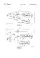
- FIG. 1is a partial block diagram of a television receiver constructed in accordance with a first aspect of the invention.
- FIG. 2is a partial block diagram of a television receiver constructed in accordance with a second aspect of the invention.
- a dashed-line block 10indicates a television receiver that includes a tuner 12 that is capable of receiving both analog and digital television signals and converting them to an IF signal.
- the IF signalis supplied to a first pole 14 a of a two-pole RF switch 14 that is selected for its low noise and loss characteristics for RF signals.
- Pole 14 ais selectively connectable to a pair of terminals A and D, with terminal A being coupled to an analog demodulator 16 and terminal D being coupled to a digital demodulator 18 .
- Switch 14has a second pole 14 b that is selectively connectable between a pair of terminals A′ and D′.
- Analog demodulator 16supplies a sync separator 20 , of conventional design, for separating the sync signals in the demodulated analog signal.
- Sync separator 20is connected to a microprocessor 22 that controls tuner 12 and the operation of switch 14 .
- microprocessor 22causes switch 14 to connect its pole 14 a to terminal A which routes the IF signal from tuner 12 to analog demodulator 16 .
- microprocessorcauses switch 14 to connect its pole 14 a to terminal D to couple the IF signal to digital demodulator 18 .
- the demodulatorsselectively develop an AGC signal, in response to the received IF signal, for controlling the gain of the tuner.
- the developed AGC signal from analog demodulator 16is coupled to terminal A′ of switch 14 and the AGC signal from digital demodulator 18 is coupled to terminal D′ of switch 14 .
- poles 14 a and 14 bcouple the IF signal from tuner 12 to analog demodulator 16 and the AGC signal from analog demodulator 16 to tuner 12 , respectively.
- switch 14is in its digital position
- the IF signal from tuner 12is coupled to digital demodulator 18 via pole 14 a and terminal D and the AGC signal is coupled back to tuner 12 from digital demodulator 18 via terminal D′ and pole 14 b.
- the embodiment of the invention in FIG. 2incorporates an RF switch 42 having a single pole that is movable between terminals A and D. Both the RF signal switching and the AGC signal switching are accomplished by switch 42 . This is achieved by multiplexing the RF signal and the AGC signal and incorporating circuitry for discriminating between the signals based upon their difference in frequency.
- a small capacitor 28couples the IF signal from tuner 12 to switch 42 and a coil 30 couples the AGC signal from switch 42 to tuner 12 .
- the AGC signalis filtered by a filter capacitor 24 that is bypassed to ground by a small capacitor 26 .
- Terminal A of switch 42is coupled through a small capacitor 32 to analog demodulator 16 for supplying the IF signal, and is supplied with the AGC signal from analog demodulator 16 through a coil 34 , the input side of which is bypassed to ground via a small capacitor 36 .
- terminal D of switch 42couples the IF signal to digital demodulator 18 by means of a small capacitor 38 and receives the AGC output of digital demodulator 18 through a coil 40 , the input side of which is bypassed to ground through a small capacitor 40 .
- microprocessor 22controls the operation of switch 42 in accordance with the type of signal (analog or digital) that is received. Specifically, the presence of syncs associated with a demodulated analog signal is communicated to the microprocessor.
- the IF signal (high frequency) pathsare through capacitors 28 , 32 and 38 and the AGC signal (low frequency) paths are through coils 30 , 34 and 40 .
- the bypass capacitors 26 , 36 and 44are provided to remove any high frequencies from the AGC signal. In the actual circuit, all capacitors are 0.001 microfarads and all coils are 10 microhenries in value.
Landscapes
- Engineering & Computer Science (AREA)
- Signal Processing (AREA)
- Multimedia (AREA)
- Computer Networks & Wireless Communication (AREA)
- Circuits Of Receivers In General (AREA)
Abstract
Description
Claims (3)
Priority Applications (2)
| Application Number | Priority Date | Filing Date | Title |
|---|---|---|---|
| US09/027,688US6348955B1 (en) | 1998-02-23 | 1998-02-23 | Tuner with switched analog and digital demodulators |
| US09/152,399US6377316B1 (en) | 1998-02-23 | 1998-09-14 | Tuner with switched analog and digital modulators |
Applications Claiming Priority (1)
| Application Number | Priority Date | Filing Date | Title |
|---|---|---|---|
| US09/027,688US6348955B1 (en) | 1998-02-23 | 1998-02-23 | Tuner with switched analog and digital demodulators |
Related Child Applications (1)
| Application Number | Title | Priority Date | Filing Date |
|---|---|---|---|
| US09/152,399Continuation-In-PartUS6377316B1 (en) | 1998-02-23 | 1998-09-14 | Tuner with switched analog and digital modulators |
Publications (1)
| Publication Number | Publication Date |
|---|---|
| US6348955B1true US6348955B1 (en) | 2002-02-19 |
Family
ID=21839210
Family Applications (1)
| Application Number | Title | Priority Date | Filing Date |
|---|---|---|---|
| US09/027,688Expired - LifetimeUS6348955B1 (en) | 1998-02-23 | 1998-02-23 | Tuner with switched analog and digital demodulators |
Country Status (1)
| Country | Link |
|---|---|
| US (1) | US6348955B1 (en) |
Cited By (45)
| Publication number | Priority date | Publication date | Assignee | Title |
|---|---|---|---|---|
| US20030001970A1 (en)* | 1999-09-27 | 2003-01-02 | General Instrument Corporation | Graphics subsystem bypass method and apparatus |
| US20040004673A1 (en)* | 2002-07-08 | 2004-01-08 | Samsung Electronics Co., Ltd. | Automatic gain control apparatus for video signal and adjusting method thereof |
| US6757029B2 (en)* | 2000-07-19 | 2004-06-29 | Sony Corporation | Television receiving apparatus |
| US20050073610A1 (en)* | 2003-03-10 | 2005-04-07 | Hitachi, Ltd. | Receiver and video display device |
| US20050179820A1 (en)* | 2004-02-17 | 2005-08-18 | Sony Corporation | System and method for TV automatic gain control (AGC) |
| EP1679888A1 (en)* | 2005-01-07 | 2006-07-12 | Samsung Electronics Co, Ltd | Television tuning apparatus for operating in analogue or digital receiving mode |
| US20090265745A1 (en)* | 2008-04-17 | 2009-10-22 | Egan Jr John M | Reversible Faceplate Terminal Adapter Which Changes Signal Flow Direction |
| US20090310026A1 (en)* | 2008-06-17 | 2009-12-17 | Masaki Yamamoto | Automatic gain control circuit |
| US20100017842A1 (en)* | 2008-07-17 | 2010-01-21 | Wells Chad T | Passive-Active Terminal Adapter and Method Having Automatic Return Loss Control |
| US20100045874A1 (en)* | 2005-01-28 | 2010-02-25 | Nxp B.V. | Intermediate frequency processing device for processing both analogue and digital television intermediate frequency signals |
| US20100095344A1 (en)* | 2008-10-13 | 2010-04-15 | Newby Charles F | Ingress Noise Inhibiting Network Interface Device and Method for Cable Television Networks |
| US20100100918A1 (en)* | 2008-10-21 | 2010-04-22 | Egan Jr John M | Multi-Port Entry Adapter, Hub and Method for Interfacing a CATV Network and a MoCA Network |
| US20100100921A1 (en)* | 2008-10-16 | 2010-04-22 | John Mezzalingua Associates, Inc. | Dynamically configurable frequency band selection device between catv distribution system and catv user |
| US20100100922A1 (en)* | 2008-10-16 | 2010-04-22 | John Mezzalingua Associates, Inc. | Downstream output level and/or output level tilt compensation device between catv distribution system and catv user |
| US20100125877A1 (en)* | 2008-10-21 | 2010-05-20 | Wells Chad T | CATV Entry Adapter and Method for Preventing Interference with eMTA Equipment from MoCA Signals |
| US20100146564A1 (en)* | 2008-10-21 | 2010-06-10 | Halik Gregory F | CATV Entry Adapter and Method Utilizing Directional Couplers for MoCA Signal Communication |
| US20100251322A1 (en)* | 2009-03-30 | 2010-09-30 | Raymond Palinkas | Upstream bandwidth conditioning device |
| US20100251323A1 (en)* | 2009-03-30 | 2010-09-30 | Jackson David H | Upstream bandwidth conditioning device |
| US20100251321A1 (en)* | 2009-03-30 | 2010-09-30 | Raymond Palinkas | Upstream bandwidth conditioning device |
| US20100251320A1 (en)* | 2009-03-30 | 2010-09-30 | Shafer Steven K | Automatic return path switching for a signal conditioning device |
| US20100244980A1 (en)* | 2009-03-30 | 2010-09-30 | Olson Thomas A | Method and apparatus for a self-terminating signal path |
| US20100251314A1 (en)* | 2009-03-30 | 2010-09-30 | John Mezzalingua Associates, Inc. | Total bandwidth conditioning device |
| US20100301972A1 (en)* | 2009-05-29 | 2010-12-02 | John Mezzalingua Associates, Inc. | Self-terminating coaxial cable port |
| US20100315942A1 (en)* | 2009-06-15 | 2010-12-16 | John Mezzalingua Associates, Inc. | Device and method for monitoring a communications system |
| US20110072472A1 (en)* | 2009-09-21 | 2011-03-24 | Wells Chad T | Passive Multi-Port Entry Adapter and Method for Preserving Downstream CATV Signal Strength within In-Home Network |
| US20110085452A1 (en)* | 2009-10-09 | 2011-04-14 | John Mezzalingua Associates, Inc. | Upstream bandwidth level measurement device |
| US20110085586A1 (en)* | 2009-10-09 | 2011-04-14 | John Mezzalingua Associates, Inc. | Total bandwidth conditioning device |
| US20110088077A1 (en)* | 2009-10-09 | 2011-04-14 | John Mezzalingua Associates, Inc. | Downstream bandwidth conditioning device |
| US20110085045A1 (en)* | 2009-10-09 | 2011-04-14 | John Mezzalingua Associates, Inc. | Modulation analyzer and level measurement device |
| US20110181371A1 (en)* | 2010-01-26 | 2011-07-28 | John Mezzalingua Associates, Inc. | Band selective isolation bridge for splitter |
| US20110187481A1 (en)* | 2010-02-01 | 2011-08-04 | John Mezzalingua Associates, Inc. | Multipath mitigation circuit for home network |
| US8141122B2 (en) | 2009-03-30 | 2012-03-20 | John Mezzalingua Associates, Inc. | RF terminate/permit system |
| US8213457B2 (en) | 2009-10-09 | 2012-07-03 | John Mezzalingua Associates, Inc. | Upstream bandwidth conditioning device |
| US8218092B1 (en) | 2008-03-03 | 2012-07-10 | Csr Technology Inc. | Apparatus for receiving both analog and digital TV signals |
| US8464301B2 (en) | 2008-10-16 | 2013-06-11 | Ppc Broadband, Inc. | Upstream bandwidth conditioning device between CATV distribution system and CATV user |
| US8479247B2 (en) | 2010-04-14 | 2013-07-02 | Ppc Broadband, Inc. | Upstream bandwidth conditioning device |
| US8561125B2 (en) | 2010-08-30 | 2013-10-15 | Ppc Broadband, Inc. | Home network frequency conditioning device and method |
| US9264012B2 (en) | 2012-06-25 | 2016-02-16 | Ppc Broadband, Inc. | Radio frequency signal splitter |
| US9351051B2 (en) | 2008-10-13 | 2016-05-24 | Ppc Broadband, Inc. | CATV entry adapter and method for distributing CATV and in-home entertainment signals |
| US10021343B2 (en) | 2010-12-21 | 2018-07-10 | Ppc Broadband, Inc. | Method and apparatus for reducing isolation in a home network |
| US10142677B2 (en) | 2008-10-21 | 2018-11-27 | Ppc Broadband, Inc. | Entry device for a CATV network |
| US10212392B2 (en) | 2016-06-30 | 2019-02-19 | Ppc Broadband, Inc. | Passive enhanced MoCA entry device |
| US10389453B2 (en) | 2009-12-15 | 2019-08-20 | Interdigital Madison Patent Holdings | Multiplexed RFAGC for frequency diversity receivers |
| US11076191B2 (en) | 2018-01-19 | 2021-07-27 | Ppc Broadband, Inc. | Systems and methods for extending an in-home splitter network |
| US11910052B2 (en) | 2008-10-21 | 2024-02-20 | Ppc Broadband, Inc. | Entry device for communicating external network signals and in-home network signals |
Citations (8)
| Publication number | Priority date | Publication date | Assignee | Title |
|---|---|---|---|---|
| US5418815A (en)* | 1992-06-12 | 1995-05-23 | Kabushiki Kaisha Toshiba | Receiver adaptively operable for multiple signal transmission systems |
| US5638112A (en)* | 1995-08-07 | 1997-06-10 | Zenith Electronics Corp. | Hybrid analog/digital STB |
| US5774195A (en)* | 1995-01-24 | 1998-06-30 | Kabushiki Kaisha Toshiba | Broadcasting system discriminating television receiver for differentiating between analog and digital telecast signals |
| US5825833A (en)* | 1995-01-31 | 1998-10-20 | Mitsumi Electric Co., Ltd. | Digital and analog reception apparatus |
| US5956098A (en)* | 1994-02-14 | 1999-09-21 | Hitachi, Ltd. | Digital broadcasting receiver |
| US6005640A (en)* | 1996-09-27 | 1999-12-21 | Sarnoff Corporation | Multiple modulation format television signal receiver system |
| US6014178A (en)* | 1995-09-29 | 2000-01-11 | Samsung Electronics Co., Ltd. | Receiver having analog and digital video modes and receiving method thereof |
| US6016170A (en)* | 1995-09-25 | 2000-01-18 | Alps Electric Co., Ltd. | Double conversion television tuner |
- 1998
- 1998-02-23USUS09/027,688patent/US6348955B1/ennot_activeExpired - Lifetime
Patent Citations (8)
| Publication number | Priority date | Publication date | Assignee | Title |
|---|---|---|---|---|
| US5418815A (en)* | 1992-06-12 | 1995-05-23 | Kabushiki Kaisha Toshiba | Receiver adaptively operable for multiple signal transmission systems |
| US5956098A (en)* | 1994-02-14 | 1999-09-21 | Hitachi, Ltd. | Digital broadcasting receiver |
| US5774195A (en)* | 1995-01-24 | 1998-06-30 | Kabushiki Kaisha Toshiba | Broadcasting system discriminating television receiver for differentiating between analog and digital telecast signals |
| US5825833A (en)* | 1995-01-31 | 1998-10-20 | Mitsumi Electric Co., Ltd. | Digital and analog reception apparatus |
| US5638112A (en)* | 1995-08-07 | 1997-06-10 | Zenith Electronics Corp. | Hybrid analog/digital STB |
| US6016170A (en)* | 1995-09-25 | 2000-01-18 | Alps Electric Co., Ltd. | Double conversion television tuner |
| US6014178A (en)* | 1995-09-29 | 2000-01-11 | Samsung Electronics Co., Ltd. | Receiver having analog and digital video modes and receiving method thereof |
| US6005640A (en)* | 1996-09-27 | 1999-12-21 | Sarnoff Corporation | Multiple modulation format television signal receiver system |
Cited By (106)
| Publication number | Priority date | Publication date | Assignee | Title |
|---|---|---|---|---|
| US20030001970A1 (en)* | 1999-09-27 | 2003-01-02 | General Instrument Corporation | Graphics subsystem bypass method and apparatus |
| US7116377B2 (en)* | 1999-09-27 | 2006-10-03 | General Instrument Corporation | Graphics subsystem bypass method and apparatus |
| US6757029B2 (en)* | 2000-07-19 | 2004-06-29 | Sony Corporation | Television receiving apparatus |
| US7081926B2 (en)* | 2002-07-08 | 2006-07-25 | Samsung Electronics Co., Ltd. | Automatic gain control apparatus for video signal and adjusting method thereof |
| US20040004673A1 (en)* | 2002-07-08 | 2004-01-08 | Samsung Electronics Co., Ltd. | Automatic gain control apparatus for video signal and adjusting method thereof |
| US20050073610A1 (en)* | 2003-03-10 | 2005-04-07 | Hitachi, Ltd. | Receiver and video display device |
| US20050179820A1 (en)* | 2004-02-17 | 2005-08-18 | Sony Corporation | System and method for TV automatic gain control (AGC) |
| US7053961B2 (en)* | 2004-02-17 | 2006-05-30 | Sony Corporation | System and method for TV automatic gain control (AGC) |
| US20060152637A1 (en)* | 2005-01-07 | 2006-07-13 | Samsung Electronics Co., Ltd. | Image display apparatus capable of analog/digital tuning with digital television tuner and analog/digital tuning method thereof |
| EP1679888A1 (en)* | 2005-01-07 | 2006-07-12 | Samsung Electronics Co, Ltd | Television tuning apparatus for operating in analogue or digital receiving mode |
| US8614769B2 (en)* | 2005-01-28 | 2013-12-24 | Nxp, B.V. | Intermediate frequency processing device for processing both analogue and digital television intermediate frequency signals |
| US20100045874A1 (en)* | 2005-01-28 | 2010-02-25 | Nxp B.V. | Intermediate frequency processing device for processing both analogue and digital television intermediate frequency signals |
| US8218092B1 (en) | 2008-03-03 | 2012-07-10 | Csr Technology Inc. | Apparatus for receiving both analog and digital TV signals |
| US20090265745A1 (en)* | 2008-04-17 | 2009-10-22 | Egan Jr John M | Reversible Faceplate Terminal Adapter Which Changes Signal Flow Direction |
| US20090310026A1 (en)* | 2008-06-17 | 2009-12-17 | Masaki Yamamoto | Automatic gain control circuit |
| US8130324B2 (en) | 2008-06-17 | 2012-03-06 | Alps Electronic Co., Ltd. | Automatic gain control circuit |
| EP2136470A3 (en)* | 2008-06-17 | 2010-10-13 | Alps Electric Co., Ltd. | Automatic gain control circuit |
| US20100017842A1 (en)* | 2008-07-17 | 2010-01-21 | Wells Chad T | Passive-Active Terminal Adapter and Method Having Automatic Return Loss Control |
| US10257462B2 (en) | 2008-07-17 | 2019-04-09 | Ppc Broadband, Inc. | Adapter for a cable-television network |
| US9363469B2 (en) | 2008-07-17 | 2016-06-07 | Ppc Broadband, Inc. | Passive-active terminal adapter and method having automatic return loss control |
| US9769418B2 (en) | 2008-07-17 | 2017-09-19 | Ppc Broadband, Inc. | Passive-active terminal adapter and method having automatic return loss control |
| US9351051B2 (en) | 2008-10-13 | 2016-05-24 | Ppc Broadband, Inc. | CATV entry adapter and method for distributing CATV and in-home entertainment signals |
| US9647851B2 (en) | 2008-10-13 | 2017-05-09 | Ppc Broadband, Inc. | Ingress noise inhibiting network interface device and method for cable television networks |
| US20100095344A1 (en)* | 2008-10-13 | 2010-04-15 | Newby Charles F | Ingress Noise Inhibiting Network Interface Device and Method for Cable Television Networks |
| US9781472B2 (en) | 2008-10-13 | 2017-10-03 | Ppc Broadband, Inc. | CATV entry adapter and method for distributing CATV and in-home entertainment signals |
| US10045056B2 (en) | 2008-10-13 | 2018-08-07 | Ppc Broadband, Inc. | Ingress noise inhibiting network interface device and method for cable television networks |
| US10154302B2 (en) | 2008-10-13 | 2018-12-11 | Ppc Broadband, Inc. | CATV entry adapter and method for distributing CATV and in-home entertainment signals |
| US10187673B2 (en) | 2008-10-13 | 2019-01-22 | Ppc Broadband, Inc. | Ingress noise inhibiting network interface device and method for cable television networks |
| US8001579B2 (en) | 2008-10-16 | 2011-08-16 | John Mezzalingua Associates, Inc. | Downstream output level and/or output level tilt compensation device between CATV distribution system and CATV user |
| US20100100922A1 (en)* | 2008-10-16 | 2010-04-22 | John Mezzalingua Associates, Inc. | Downstream output level and/or output level tilt compensation device between catv distribution system and catv user |
| US8832767B2 (en) | 2008-10-16 | 2014-09-09 | Ppc Broadband, Inc. | Dynamically configurable frequency band selection device between CATV distribution system and CATV user |
| US10264325B2 (en) | 2008-10-16 | 2019-04-16 | Ppc Broadband, Inc. | System, method and device having teaching and commerce subsystems |
| US8464301B2 (en) | 2008-10-16 | 2013-06-11 | Ppc Broadband, Inc. | Upstream bandwidth conditioning device between CATV distribution system and CATV user |
| US9271026B2 (en) | 2008-10-16 | 2016-02-23 | Ppc Broadband, Inc. | Dynamically configurable frequency band selection device between CATV distribution system and CATV user |
| US20100100921A1 (en)* | 2008-10-16 | 2010-04-22 | John Mezzalingua Associates, Inc. | Dynamically configurable frequency band selection device between catv distribution system and catv user |
| US10924811B2 (en) | 2008-10-16 | 2021-02-16 | Ppc Broadband, Inc. | Compensation device for maintaining a desired signal quality in transmitted signals |
| US10154303B2 (en) | 2008-10-21 | 2018-12-11 | Ppc Broadband, Inc. | Entry adapter that blocks different frequency bands and preserves downstream signal strength |
| US11528526B2 (en) | 2008-10-21 | 2022-12-13 | Ppc Broadband, Inc. | Entry device for communicating external network signals and in-home network signals |
| US10149004B2 (en) | 2008-10-21 | 2018-12-04 | Ppc Broadband, Inc. | Entry device and method for communicating CATV signals and MoCA in-home network signals in an entry device |
| US20100100918A1 (en)* | 2008-10-21 | 2010-04-22 | Egan Jr John M | Multi-Port Entry Adapter, Hub and Method for Interfacing a CATV Network and a MoCA Network |
| US10142677B2 (en) | 2008-10-21 | 2018-11-27 | Ppc Broadband, Inc. | Entry device for a CATV network |
| US20100125877A1 (en)* | 2008-10-21 | 2010-05-20 | Wells Chad T | CATV Entry Adapter and Method for Preventing Interference with eMTA Equipment from MoCA Signals |
| US10419813B2 (en) | 2008-10-21 | 2019-09-17 | Ppc Broadband, Inc. | Passive multi-port entry adapter for preserving downstream CATV signal strength |
| US10917685B2 (en) | 2008-10-21 | 2021-02-09 | Ppc Broadband, Inc. | Entry device for communicating signals between an external network and an in-home network |
| US10284904B2 (en) | 2008-10-21 | 2019-05-07 | Ppc Broadband, Inc. | Entry adapters for conducting can signals and in-home network signals |
| US10154304B2 (en) | 2008-10-21 | 2018-12-11 | Ppc Broadband, Inc. | Methods for controlling CATV signal communication between a CATV network and an in-home network, and preserving downstream CATV signal strength within the in-home network |
| US8286209B2 (en) | 2008-10-21 | 2012-10-09 | John Mezzalingua Associates, Inc. | Multi-port entry adapter, hub and method for interfacing a CATV network and a MoCA network |
| US11910052B2 (en) | 2008-10-21 | 2024-02-20 | Ppc Broadband, Inc. | Entry device for communicating external network signals and in-home network signals |
| US20100146564A1 (en)* | 2008-10-21 | 2010-06-10 | Halik Gregory F | CATV Entry Adapter and Method Utilizing Directional Couplers for MoCA Signal Communication |
| US10341719B2 (en) | 2008-10-21 | 2019-07-02 | Ppc Broadband, Inc. | Entry adapter for communicating external signals to an internal network and communicating client signals in the client network |
| US8429695B2 (en) | 2008-10-21 | 2013-04-23 | Ppc Broadband, Inc. | CATV entry adapter and method utilizing directional couplers for MoCA signal communication |
| US10341718B2 (en) | 2008-10-21 | 2019-07-02 | Ppc Broadband, Inc. | Passive multi-port entry adapter and method for preserving downstream CATV signal strength within in-home network |
| US10284903B2 (en) | 2008-10-21 | 2019-05-07 | Ppc Broadband, Inc. | Entry adapters for frequency band blocking internal network signals |
| US8510782B2 (en) | 2008-10-21 | 2013-08-13 | Ppc Broadband, Inc. | CATV entry adapter and method for preventing interference with eMTA equipment from MoCA Signals |
| US20100251314A1 (en)* | 2009-03-30 | 2010-09-30 | John Mezzalingua Associates, Inc. | Total bandwidth conditioning device |
| US8990881B2 (en) | 2009-03-30 | 2015-03-24 | Ppc Broadband, Inc. | Upstream bandwidth conditioning device |
| US20100251322A1 (en)* | 2009-03-30 | 2010-09-30 | Raymond Palinkas | Upstream bandwidth conditioning device |
| US8584192B2 (en) | 2009-03-30 | 2013-11-12 | Ppc Broadband, Inc. | Upstream bandwidth conditioning device |
| US20100251323A1 (en)* | 2009-03-30 | 2010-09-30 | Jackson David H | Upstream bandwidth conditioning device |
| US20100251321A1 (en)* | 2009-03-30 | 2010-09-30 | Raymond Palinkas | Upstream bandwidth conditioning device |
| US20100251320A1 (en)* | 2009-03-30 | 2010-09-30 | Shafer Steven K | Automatic return path switching for a signal conditioning device |
| US8179814B2 (en) | 2009-03-30 | 2012-05-15 | John Mezzalingua Associates, Inc. | Automatic return path switching for a signal conditioning device |
| US20100244980A1 (en)* | 2009-03-30 | 2010-09-30 | Olson Thomas A | Method and apparatus for a self-terminating signal path |
| US8181211B2 (en) | 2009-03-30 | 2012-05-15 | John Mezzalingua Associates, Inc. | Total bandwidth conditioning device |
| US8082570B2 (en) | 2009-03-30 | 2011-12-20 | John Mezzalingua Associates, Inc. | Method and apparatus for a self-terminating signal path |
| US8141122B2 (en) | 2009-03-30 | 2012-03-20 | John Mezzalingua Associates, Inc. | RF terminate/permit system |
| US8098113B2 (en) | 2009-05-29 | 2012-01-17 | John Mezzalingua Associates, Inc. | Self-terminating coaxial cable port |
| US20100301972A1 (en)* | 2009-05-29 | 2010-12-02 | John Mezzalingua Associates, Inc. | Self-terminating coaxial cable port |
| US20100315942A1 (en)* | 2009-06-15 | 2010-12-16 | John Mezzalingua Associates, Inc. | Device and method for monitoring a communications system |
| US8854947B2 (en) | 2009-06-15 | 2014-10-07 | Ppc Broadband, Inc. | Device and method for monitoring a communications system |
| US20110072472A1 (en)* | 2009-09-21 | 2011-03-24 | Wells Chad T | Passive Multi-Port Entry Adapter and Method for Preserving Downstream CATV Signal Strength within In-Home Network |
| US9167286B2 (en) | 2009-09-21 | 2015-10-20 | Ppc Broadband, Inc. | Passive multi-port entry adapter and method for preserving downstream CATV signal strength within in-home network |
| US9516376B2 (en) | 2009-09-21 | 2016-12-06 | Ppc Broadband, Inc. | Passive multi-port entry adapter and method for preserving downstream CATV signal strength within in-home network |
| US9860591B2 (en) | 2009-09-21 | 2018-01-02 | Ppc Broadband, Inc. | Passive multi-port entry adapter and method for preserving downstream CATV signal strength within in-home network |
| US8356322B2 (en) | 2009-09-21 | 2013-01-15 | John Mezzalingua Associates, Inc. | Passive multi-port entry adapter and method for preserving downstream CATV signal strength within in-home network |
| US8516537B2 (en) | 2009-10-09 | 2013-08-20 | Ppc Broadband, Inc. | Downstream bandwidth conditioning device |
| US8213457B2 (en) | 2009-10-09 | 2012-07-03 | John Mezzalingua Associates, Inc. | Upstream bandwidth conditioning device |
| US8274566B2 (en) | 2009-10-09 | 2012-09-25 | John Mezzalingua Associates, Inc. | Modulation analyzer and level measurement device |
| US8385219B2 (en) | 2009-10-09 | 2013-02-26 | John Mezzalingua Associates, Inc. | Upstream bandwidth level measurement device |
| US20110085586A1 (en)* | 2009-10-09 | 2011-04-14 | John Mezzalingua Associates, Inc. | Total bandwidth conditioning device |
| US20110085045A1 (en)* | 2009-10-09 | 2011-04-14 | John Mezzalingua Associates, Inc. | Modulation analyzer and level measurement device |
| US20110085452A1 (en)* | 2009-10-09 | 2011-04-14 | John Mezzalingua Associates, Inc. | Upstream bandwidth level measurement device |
| US20110088077A1 (en)* | 2009-10-09 | 2011-04-14 | John Mezzalingua Associates, Inc. | Downstream bandwidth conditioning device |
| US10389453B2 (en) | 2009-12-15 | 2019-08-20 | Interdigital Madison Patent Holdings | Multiplexed RFAGC for frequency diversity receivers |
| US8350641B2 (en) | 2010-01-26 | 2013-01-08 | John Mezzalingua Associates, Inc. | Band selective isolation bridge for splitter |
| US20110181371A1 (en)* | 2010-01-26 | 2011-07-28 | John Mezzalingua Associates, Inc. | Band selective isolation bridge for splitter |
| US10284162B2 (en) | 2010-02-01 | 2019-05-07 | Ppc Broadband, Inc. | Multipath mitigation circuit for home network |
| US10790793B2 (en) | 2010-02-01 | 2020-09-29 | Ppc Broadband, Inc. | Filter circuit |
| US20110187481A1 (en)* | 2010-02-01 | 2011-08-04 | John Mezzalingua Associates, Inc. | Multipath mitigation circuit for home network |
| US9306530B2 (en) | 2010-02-01 | 2016-04-05 | Ppc Broadband, Inc. | Multipath mitigation circuit for home network |
| US8487717B2 (en) | 2010-02-01 | 2013-07-16 | Ppc Broadband, Inc. | Multipath mitigation circuit for home network |
| US11444592B2 (en) | 2010-02-01 | 2022-09-13 | Ppc Broadband, Inc. | Filter circuit |
| US9979373B2 (en) | 2010-02-01 | 2018-05-22 | Ppc Broadband, Inc. | Multipath mitigation circuit for home network |
| US8479247B2 (en) | 2010-04-14 | 2013-07-02 | Ppc Broadband, Inc. | Upstream bandwidth conditioning device |
| US8561125B2 (en) | 2010-08-30 | 2013-10-15 | Ppc Broadband, Inc. | Home network frequency conditioning device and method |
| US11070766B2 (en) | 2010-12-21 | 2021-07-20 | Ppc Broadband, Inc. | Method and apparatus for reducing isolation in a home network |
| US10750120B2 (en) | 2010-12-21 | 2020-08-18 | Ppc Broadband, Inc. | Method and apparatus for reducing isolation in a home network |
| US10021343B2 (en) | 2010-12-21 | 2018-07-10 | Ppc Broadband, Inc. | Method and apparatus for reducing isolation in a home network |
| US9929457B2 (en) | 2012-06-25 | 2018-03-27 | Ppc Broadband, Inc. | Radio frequency signal splitter |
| US9641147B2 (en) | 2012-06-25 | 2017-05-02 | Ppc Broadband, Inc. | Radio frequency signal splitter |
| US9264012B2 (en) | 2012-06-25 | 2016-02-16 | Ppc Broadband, Inc. | Radio frequency signal splitter |
| US10582160B2 (en) | 2016-06-30 | 2020-03-03 | Ppc Broadband, Inc. | MoCA entry device |
| US11076129B2 (en) | 2016-06-30 | 2021-07-27 | Ppc Broadband, Inc. | MoCA entry device |
| US11647162B2 (en) | 2016-06-30 | 2023-05-09 | Ppc Broadband, Inc. | MoCA entry device |
| US10212392B2 (en) | 2016-06-30 | 2019-02-19 | Ppc Broadband, Inc. | Passive enhanced MoCA entry device |
| US11076191B2 (en) | 2018-01-19 | 2021-07-27 | Ppc Broadband, Inc. | Systems and methods for extending an in-home splitter network |
Similar Documents
| Publication | Publication Date | Title |
|---|---|---|
| US6348955B1 (en) | Tuner with switched analog and digital demodulators | |
| US6377316B1 (en) | Tuner with switched analog and digital modulators | |
| US5673088A (en) | Multi-broadcast selection apparatus | |
| JP2596488Y2 (en) | Filter circuit | |
| US5835853A (en) | Two band receiver | |
| KR0157485B1 (en) | Variable gain amplifier | |
| US6678011B2 (en) | Fronted circuit | |
| KR20020020790A (en) | GPS receiver | |
| US8614769B2 (en) | Intermediate frequency processing device for processing both analogue and digital television intermediate frequency signals | |
| EP0819355B1 (en) | Multi-standard signal reception | |
| KR20080007722A (en) | Digital Dual Tuner with Output Selection of RF Loop-Through | |
| KR920004944Y1 (en) | Sound multiplex demodulation circuit of 12/nicam common using | |
| KR100246708B1 (en) | Automatic Gain Control Circuit | |
| JP2803683B2 (en) | Diversity receiver | |
| KR100508426B1 (en) | Tuner for enable receving broadcasting of all type | |
| CA1289196C (en) | Fmx stereophonic broadcaster receiver | |
| JPS61230536A (en) | Frequency separation circuit | |
| JP2924230B2 (en) | Multi-system television receiver with built-in audio multiplex receiver | |
| US20020098822A1 (en) | Amplifier circuit arrangement for alternatively processing a digital or an analog signal | |
| KR100335743B1 (en) | Circuit for dividing frequency in receiver | |
| KR970006133Y1 (en) | Pal/ntsc mode converting circuit for satellite communication | |
| JPS63202121A (en) | Switching connecting circuit arrangement | |
| JPH0738819A (en) | Antenna input device of tuner | |
| JP2671164B2 (en) | Video / audio intermediate frequency amplification circuit | |
| JPH0685570B2 (en) | Tuner circuit in a television receiver |
Legal Events
| Date | Code | Title | Description |
|---|---|---|---|
| AS | Assignment | Owner name:ZENITH ELECTRONICS CORPORATION, ILLINOIS Free format text:ASSIGNMENT OF ASSIGNORS INTEREST;ASSIGNOR:TAIT, DAVID S.;REEL/FRAME:009229/0378 Effective date:19980223 | |
| AS | Assignment | Owner name:CITICORP NORTH AMERICA, INC., AS AGENT, NEW YORK Free format text:SECURITY AGREEMENT;ASSIGNOR:ZENITH ELECTRONICS CORPORATION;REEL/FRAME:010470/0414 Effective date:19991109 | |
| AS | Assignment | Owner name:LG ELECTRONICS INC., KOREA, REPUBLIC OF Free format text:SECURITY AGREEMENT;ASSIGNOR:ZENITH ELECTRONICS CORPORATION;REEL/FRAME:010618/0424 Effective date:19991109 | |
| AS | Assignment | Owner name:ZENITH ELECTRONICS CORPORATION, ILLINOIS Free format text:RELEASE OF SECURITY INTEREST;ASSIGNOR:CITICORP NORTH AMERICA, INC.;REEL/FRAME:012188/0204 Effective date:20010822 | |
| FEPP | Fee payment procedure | Free format text:PAYOR NUMBER ASSIGNED (ORIGINAL EVENT CODE: ASPN); ENTITY STATUS OF PATENT OWNER: LARGE ENTITY | |
| STCF | Information on status: patent grant | Free format text:PATENTED CASE | |
| FPAY | Fee payment | Year of fee payment:4 | |
| FEPP | Fee payment procedure | Free format text:PAYER NUMBER DE-ASSIGNED (ORIGINAL EVENT CODE: RMPN); ENTITY STATUS OF PATENT OWNER: LARGE ENTITY Free format text:PAYOR NUMBER ASSIGNED (ORIGINAL EVENT CODE: ASPN); ENTITY STATUS OF PATENT OWNER: LARGE ENTITY | |
| AS | Assignment | Owner name:ZENITH ELECTRONICS LLC, ILLINOIS Free format text:CONVERSION;ASSIGNOR:ZENITH ELECTRONICS CORPORATION;REEL/FRAME:020654/0328 Effective date:20070131 | |
| AS | Assignment | Owner name:LG ELECTRONICS INC., KOREA, REPUBLIC OF Free format text:ASSIGNMENT OF ASSIGNORS INTEREST;ASSIGNOR:ZENITH ELECTRONICS LLC;REEL/FRAME:020794/0890 Effective date:20080415 | |
| FPAY | Fee payment | Year of fee payment:8 | |
| FEPP | Fee payment procedure | Free format text:PAYER NUMBER DE-ASSIGNED (ORIGINAL EVENT CODE: RMPN); ENTITY STATUS OF PATENT OWNER: LARGE ENTITY Free format text:PAYOR NUMBER ASSIGNED (ORIGINAL EVENT CODE: ASPN); ENTITY STATUS OF PATENT OWNER: LARGE ENTITY | |
| FPAY | Fee payment | Year of fee payment:12 |