US6348688B1 - Tandem time-of-flight mass spectrometer with delayed extraction and method for use - Google Patents
Tandem time-of-flight mass spectrometer with delayed extraction and method for useDownload PDFInfo
- Publication number
- US6348688B1 US6348688B1US09/233,703US23370399AUS6348688B1US 6348688 B1US6348688 B1US 6348688B1US 23370399 AUS23370399 AUS 23370399AUS 6348688 B1US6348688 B1US 6348688B1
- Authority
- US
- United States
- Prior art keywords
- ions
- ion
- mass
- mass spectrometer
- timed
- Prior art date
- Legal status (The legal status is an assumption and is not a legal conclusion. Google has not performed a legal analysis and makes no representation as to the accuracy of the status listed.)
- Expired - Lifetime
Links
- 238000000605extractionMethods0.000titleclaimsabstractdescription70
- 230000003111delayed effectEffects0.000titleclaimsabstractdescription21
- 238000000034methodMethods0.000titleclaimsdescription16
- 150000002500ionsChemical class0.000claimsabstractdescription462
- 238000013467fragmentationMethods0.000claimsabstractdescription62
- 238000006062fragmentation reactionMethods0.000claimsabstractdescription62
- 239000012634fragmentSubstances0.000claimsabstractdescription42
- 238000004891communicationMethods0.000claimsabstractdescription19
- 238000001269time-of-flight mass spectrometryMethods0.000claimsabstractdescription8
- 230000007935neutral effectEffects0.000claimsdescription20
- 238000006303photolysis reactionMethods0.000claimsdescription7
- 230000005540biological transmissionEffects0.000claimsdescription5
- 238000010494dissociation reactionMethods0.000claimsdescription5
- 230000005593dissociationsEffects0.000claimsdescription5
- 239000011159matrix materialSubstances0.000claimsdescription4
- 230000005405multipoleEffects0.000claimsdescription4
- 238000004885tandem mass spectrometryMethods0.000claimsdescription4
- 238000000451chemical ionisationMethods0.000claimsdescription3
- 238000003795desorptionMethods0.000claimsdescription3
- 238000002347injectionMethods0.000claimsdescription3
- 239000007924injectionSubstances0.000claimsdescription3
- 239000007788liquidSubstances0.000claimsdescription3
- 239000007787solidSubstances0.000claimsdescription2
- 239000012530fluidSubstances0.000claims5
- 239000000284extractSubstances0.000claims2
- 230000003993interactionEffects0.000claims2
- 230000003213activating effectEffects0.000claims1
- 230000008878couplingEffects0.000claims1
- 238000010168coupling processMethods0.000claims1
- 238000005859coupling reactionMethods0.000claims1
- 239000000523sampleSubstances0.000description25
- 239000007789gasSubstances0.000description23
- 230000005684electric fieldEffects0.000description20
- 230000001133accelerationEffects0.000description13
- 238000010586diagramMethods0.000description13
- 238000010884ion-beam techniqueMethods0.000description9
- 238000001228spectrumMethods0.000description8
- 238000005259measurementMethods0.000description5
- 238000009826distributionMethods0.000description4
- 238000004519manufacturing processMethods0.000description4
- 108090000765processed proteins & peptidesProteins0.000description4
- 230000035945sensitivityEffects0.000description4
- 238000002366time-of-flight methodMethods0.000description4
- 238000004458analytical methodMethods0.000description3
- 238000001514detection methodMethods0.000description3
- XKRFYHLGVUSROY-UHFFFAOYSA-NArgonChemical compound[Ar]XKRFYHLGVUSROY-UHFFFAOYSA-N0.000description2
- IJGRMHOSHXDMSA-UHFFFAOYSA-NAtomic nitrogenChemical compoundN#NIJGRMHOSHXDMSA-UHFFFAOYSA-N0.000description2
- RTZKZFJDLAIYFH-UHFFFAOYSA-NDiethyl etherChemical compoundCCOCCRTZKZFJDLAIYFH-UHFFFAOYSA-N0.000description2
- 108091034117OligonucleotideProteins0.000description2
- JLCPHMBAVCMARE-UHFFFAOYSA-N[3-[[3-[[3-[[3-[[3-[[3-[[3-[[3-[[3-[[3-[[3-[[5-(2-amino-6-oxo-1H-purin-9-yl)-3-[[3-[[3-[[3-[[3-[[3-[[5-(2-amino-6-oxo-1H-purin-9-yl)-3-[[5-(2-amino-6-oxo-1H-purin-9-yl)-3-hydroxyoxolan-2-yl]methoxy-hydroxyphosphoryl]oxyoxolan-2-yl]methoxy-hydroxyphosphoryl]oxy-5-(5-methyl-2,4-dioxopyrimidin-1-yl)oxolan-2-yl]methoxy-hydroxyphosphoryl]oxy-5-(6-aminopurin-9-yl)oxolan-2-yl]methoxy-hydroxyphosphoryl]oxy-5-(6-aminopurin-9-yl)oxolan-2-yl]methoxy-hydroxyphosphoryl]oxy-5-(6-aminopurin-9-yl)oxolan-2-yl]methoxy-hydroxyphosphoryl]oxy-5-(6-aminopurin-9-yl)oxolan-2-yl]methoxy-hydroxyphosphoryl]oxyoxolan-2-yl]methoxy-hydroxyphosphoryl]oxy-5-(5-methyl-2,4-dioxopyrimidin-1-yl)oxolan-2-yl]methoxy-hydroxyphosphoryl]oxy-5-(4-amino-2-oxopyrimidin-1-yl)oxolan-2-yl]methoxy-hydroxyphosphoryl]oxy-5-(5-methyl-2,4-dioxopyrimidin-1-yl)oxolan-2-yl]methoxy-hydroxyphosphoryl]oxy-5-(5-methyl-2,4-dioxopyrimidin-1-yl)oxolan-2-yl]methoxy-hydroxyphosphoryl]oxy-5-(6-aminopurin-9-yl)oxolan-2-yl]methoxy-hydroxyphosphoryl]oxy-5-(6-aminopurin-9-yl)oxolan-2-yl]methoxy-hydroxyphosphoryl]oxy-5-(4-amino-2-oxopyrimidin-1-yl)oxolan-2-yl]methoxy-hydroxyphosphoryl]oxy-5-(4-amino-2-oxopyrimidin-1-yl)oxolan-2-yl]methoxy-hydroxyphosphoryl]oxy-5-(4-amino-2-oxopyrimidin-1-yl)oxolan-2-yl]methoxy-hydroxyphosphoryl]oxy-5-(6-aminopurin-9-yl)oxolan-2-yl]methoxy-hydroxyphosphoryl]oxy-5-(4-amino-2-oxopyrimidin-1-yl)oxolan-2-yl]methyl [5-(6-aminopurin-9-yl)-2-(hydroxymethyl)oxolan-3-yl] hydrogen phosphatePolymersCc1cn(C2CC(OP(O)(=O)OCC3OC(CC3OP(O)(=O)OCC3OC(CC3O)n3cnc4c3nc(N)[nH]c4=O)n3cnc4c3nc(N)[nH]c4=O)C(COP(O)(=O)OC3CC(OC3COP(O)(=O)OC3CC(OC3COP(O)(=O)OC3CC(OC3COP(O)(=O)OC3CC(OC3COP(O)(=O)OC3CC(OC3COP(O)(=O)OC3CC(OC3COP(O)(=O)OC3CC(OC3COP(O)(=O)OC3CC(OC3COP(O)(=O)OC3CC(OC3COP(O)(=O)OC3CC(OC3COP(O)(=O)OC3CC(OC3COP(O)(=O)OC3CC(OC3COP(O)(=O)OC3CC(OC3COP(O)(=O)OC3CC(OC3COP(O)(=O)OC3CC(OC3COP(O)(=O)OC3CC(OC3COP(O)(=O)OC3CC(OC3CO)n3cnc4c(N)ncnc34)n3ccc(N)nc3=O)n3cnc4c(N)ncnc34)n3ccc(N)nc3=O)n3ccc(N)nc3=O)n3ccc(N)nc3=O)n3cnc4c(N)ncnc34)n3cnc4c(N)ncnc34)n3cc(C)c(=O)[nH]c3=O)n3cc(C)c(=O)[nH]c3=O)n3ccc(N)nc3=O)n3cc(C)c(=O)[nH]c3=O)n3cnc4c3nc(N)[nH]c4=O)n3cnc4c(N)ncnc34)n3cnc4c(N)ncnc34)n3cnc4c(N)ncnc34)n3cnc4c(N)ncnc34)O2)c(=O)[nH]c1=OJLCPHMBAVCMARE-UHFFFAOYSA-N0.000description2
- 238000004364calculation methodMethods0.000description2
- 150000001793charged compoundsChemical class0.000description2
- 238000009616inductively coupled plasmaMethods0.000description2
- 238000001819mass spectrumMethods0.000description2
- 238000001840matrix-assisted laser desorption--ionisation time-of-flight mass spectrometryMethods0.000description2
- 239000002245particleSubstances0.000description2
- 230000003094perturbing effectEffects0.000description2
- 102000004196processed proteins & peptidesHuman genes0.000description2
- 238000012163sequencing techniqueMethods0.000description2
- 230000001360synchronised effectEffects0.000description2
- 238000010521absorption reactionMethods0.000description1
- 239000003570airSubstances0.000description1
- 125000003275alpha amino acid groupChemical group0.000description1
- 238000013459approachMethods0.000description1
- 229910052786argonInorganic materials0.000description1
- 239000012472biological sampleSubstances0.000description1
- 230000015572biosynthetic processEffects0.000description1
- 230000015556catabolic processEffects0.000description1
- 238000012937correctionMethods0.000description1
- 230000001934delayEffects0.000description1
- 238000011161developmentMethods0.000description1
- 230000003292diminished effectEffects0.000description1
- 239000006185dispersionSubstances0.000description1
- 239000001307heliumSubstances0.000description1
- 229910052734heliumInorganic materials0.000description1
- SWQJXJOGLNCZEY-UHFFFAOYSA-Nhelium atomChemical compound[He]SWQJXJOGLNCZEY-UHFFFAOYSA-N0.000description1
- 230000000977initiatory effectEffects0.000description1
- 229910052743kryptonInorganic materials0.000description1
- DNNSSWSSYDEUBZ-UHFFFAOYSA-Nkrypton atomChemical compound[Kr]DNNSSWSSYDEUBZ-UHFFFAOYSA-N0.000description1
- 238000001698laser desorption ionisationMethods0.000description1
- 229910052757nitrogenInorganic materials0.000description1
- 229920001542oligosaccharidePolymers0.000description1
- 150000002482oligosaccharidesChemical class0.000description1
- 238000009304pastoral farmingMethods0.000description1
- 230000035515penetrationEffects0.000description1
- 238000005381potential energyMethods0.000description1
- 230000001902propagating effectEffects0.000description1
- 230000005855radiationEffects0.000description1
- 238000000926separation methodMethods0.000description1
- 150000003384small moleculesChemical class0.000description1
- 238000001196time-of-flight mass spectrumMethods0.000description1
- 229910052724xenonInorganic materials0.000description1
- FHNFHKCVQCLJFQ-UHFFFAOYSA-Nxenon atomChemical compound[Xe]FHNFHKCVQCLJFQ-UHFFFAOYSA-N0.000description1
Images


Classifications
- H—ELECTRICITY
- H01—ELECTRIC ELEMENTS
- H01J—ELECTRIC DISCHARGE TUBES OR DISCHARGE LAMPS
- H01J49/00—Particle spectrometers or separator tubes
- H01J49/02—Details
- H01J49/06—Electron- or ion-optical arrangements
- H01J49/061—Ion deflecting means, e.g. ion gates
- H—ELECTRICITY
- H01—ELECTRIC ELEMENTS
- H01J—ELECTRIC DISCHARGE TUBES OR DISCHARGE LAMPS
- H01J49/00—Particle spectrometers or separator tubes
- H01J49/004—Combinations of spectrometers, tandem spectrometers, e.g. MS/MS, MSn
- H—ELECTRICITY
- H01—ELECTRIC ELEMENTS
- H01J—ELECTRIC DISCHARGE TUBES OR DISCHARGE LAMPS
- H01J49/00—Particle spectrometers or separator tubes
- H01J49/26—Mass spectrometers or separator tubes
- H01J49/34—Dynamic spectrometers
- H01J49/40—Time-of-flight spectrometers
Definitions
- the inventionrelates generally to mass spectrometers and specifically to tandem mass spectrometers.
- Mass spectrometersvaporize and ionize a sample and determine the mass-to-charge ratio of the resulting ions.
- One form of mass spectrometerdetermines the mass-to-charge ratio of an ion by measuring the amount of time it takes a given ion to migrate from the ion source, the ionized and vaporized sample, to a detector, under the influence of electric fields. The time it takes for an ion to reach the detector, for electric fields of given strengths, is a direct function of its mass and an inverse function of its charge.
- This form of mass spectrometeris termed a time-of-flight mass spectrometer.
- TOF mass spectrometershave become widely accepted, particularly for the analysis of relatively nonvolatile biomolecules, and other applications requiring high speed, high sensitivity, and/or wide mass range.
- New ionization techniquessuch as matrix-assisted laser desorption/ionization (MALDI) and electrospray (ESI) have greatly extended the mass range of molecules which can be made to produce intact molecular ions in the gas phase, and TOF has unique advantages for these applications.
- MALDImatrix-assisted laser desorption/ionization
- ESIelectrospray
- TOFhas unique advantages for these applications.
- delayed extractionfor example, as described in U.S. Pat. Nos. 5,625,184 and 5,627,360, has made high resolution and precise mass measurement routinely available with MALDI-TOF, and orthogonal injection with pulsed extraction has provided similar performance enhancements for ESI-TOF.
- MS—MStandem mass spectrometers
- a first mass analyzeris used to select a primary ion of interest, for example, a molecular ion of a particular sample, and that ion is caused to fragment by increasing its internal energy, for example, by causing the ion to collide with a neutral molecule.
- the spectrum of fragment ionsis then analyzed by a second mass analyzer, and often the structure of the primary ion can be determined by interpreting the fragmentation pattern.
- MALDI-TOFthe technique known as post-source decay (PSD) can be employed, but the fragmentation spectra are often weak and difficult to interpret. Adding a collision cell where the ions may undergo high energy collisions with neutral molecules enhances the production of low mass fragment ions and produces some additional fragmentation, but the spectra are difficult to interpret.
- fragmentationmay be produced by causing energetic collisions to occur in the interface between the atmospheric pressure electrospray and the evacuated mass spectrometer, but currently there is no means for selecting a particular primary ion.
- tandem mass spectrometryis the triple quadrupole in which the primary ion is selected by the first quadrupole, and the fragment ion spectrum is analyzed by scanning the third quadrupole.
- the second quadrupoleis typically maintained at a sufficiently high pressure and voltage that multiple low energy collisions occur.
- the resulting spectraare generally rather easy to interpret and techniques have been developed, for example, for determining the amino acid sequence of a peptide from such spectra.
- Recently hybrid instrumentshave been described in which the third quadrupole is replaced by a time-of-flight analyzer.
- time-of-flight techniquesboth for selection of a primary ion and for analysis and detection of fragment ions have been described previously.
- a tandem instrument incorporating two linear time-of-flight mass analyzers using surface-induced dissociation (SID)has been used to produce the product ions.
- SIDsurface-induced dissociation
- an ion mirrorwas added to the second mass analyzer.
- U.S. Pat. No. 5,206,508discloses a tandem mass spectrometer system, using either linear or reflecting analyzers, which is capable of obtaining tandem mass spectra for each parent ion without requiring the separation of parent ions of differing mass from each other.
- U.S. Pat. No. 5,202,563discloses a tandem time-of-flight mass spectrometer comprising a grounded vacuum housing, two reflecting-type mass analyzers coupled via a fragmentation chamber, and flight channels electrically floated with respect to the grounded vacuum housing. The application of these devices has generally been confined to relatively small molecules; none appears to provide the sensitivity and resolution required for biological applications, such as sequencing of peptides or oligonucleotides.
- both mass analyzersmust have at least unit mass resolution and good ion transmission over the mass range of interest. Above molecular weight 1000, this requirement is best met by MS—MS systems consisting of two double-focusing magnetic deflection mass spectrometers having high mass range. While these instruments provide the highest mass range and mass accuracy, they are limited in sensitivity, compared to time-of-flight, and are not readily adaptable for use with modern ionization techniques such as MALDI and electrospray. These instruments are also very complex and expensive.
- the inventionrelates to tandem time-of-flight mass spectrometry including: (1) an ion generator; (2) a timed ion selector in communication with the ion generator (3) an ion fragmentation chamber in communication with the ion selector; and (4) an analyzer in communication with the fragmentation chamber.
- the ion generatorcomprises a pulsed ion source in which the ions are accelerated so that their velocities depend on their mass-to-charge ratio.
- the pulsed ion sourcemay comprise a laser desorption ionization or a pulsed electrospray source.
- the ion generatorcomprises a continuous ionization source such as a continuous electrospray, electron impact, inductively coupled plasma, or a chemical ionization source.
- the ionsare injected into a pulsed ion source in a direction substantially orthogonal to the direction of ion travel in the drift space.
- the ionsare converted into a pulsed beam of ions and are accelerated toward the drift space by periodically applying a voltage pulse.
- the timed ion selectorcomprises a field-free drift space coupled to the pulsed ion generator at one end and coupled to a pulsed ion deflector at another end.
- the drift spacemay include a beam guide confining the ion beam near the center of the drift space to increase the ion transmission.
- the pulsed ion deflectorallows only those ions within a selected mass-to-charge ratio range to be transmitted through the ion fragmentation chamber.
- the analyzeris a time-of-flight mass spectrometer and the fragmentation chamber is a collision cell designed to cause fragmentation of ions and to delay extraction.
- the analyzerincludes an ion mirror.
- a feature of the present inventionis the use of the fragmentation chamber not only to produce fragment ions, but also to serve as a delayed extraction ion source for the analysis of the fragment ions by time-of-flight mass spectrometry. This allows high resolution time-of-flight mass spectra of fragment ions to be recorded over their entire mass range in a single acquisition.
- Another feature of the present inventionis the addition of a grid which produces a field free region between the collision cell and the acceleration region. The field free region allows the ions excited by collisions in the collision cell time to complete fragmentation.
- the inventionalso relates to the measurement of fragment mass spectra with high resolution, accuracy and sensitivity.
- the methodincludes the steps of: (1) producing a pulsed source of ions; (2) selecting ions of a specific range of mass-to-charge ratios; (3) fragmenting the ions; and (4) analyzing the fragment ions using delayed extraction time-of-flight mass spectrometry.
- the step of producing a pulsed source of ionsis performed by MALDI.
- the step of fragmenting the ionis performed by colliding the ion with molecules of a gas.
- the step of fragmenting the ionincludes the steps of exciting the ions and then passing the excited ions through a nearly field-free region to allow the excited ions enough time to substantially complete fragmentation.
- a method for high performance tandem mass spectroscopyincludes selection of the primary ions.
- the parameters controlling the pulsed ion generatorare adjusted so that the primary ions of interest are focused to a minimum peak width at the pulsed ion deflector.
- the deflectoris pulsed to allow the selected ion to be transmitted, while all other ions are deflected and are not transmitted.
- the selected ionsmay be decelerated by a predetermined amount.
- the selected ionsenter the collision cell where they are excited by collisions with neutral molecules and dissociate.
- the fragment ions, and any residual selected ionsexit the collision cell into a nearly field-free region between the cell and a grid plate maintained at approximately the same potential as the cell.
- the ion packet at this pointis very similar to that produced initially by MALDI in that all of the ions have nearly the same average velocity with some dispersion in velocity and position.
- An acceleration pulse of a predetermined amplitudeis applied to the grid plate, after a short delay from the time the ions pass through an aperture in the grid plate, the spectrum of the product ions may be recorded and the precise masses determined.
- Theorypredicts that resolution approaching 3000 for primary ion selection should be achievable with minimal loss in transmission efficiency
- the theoretical resolution for the fragment ionsis at least ten times the mass of the fragment, up to mass 2000.
- the inventionis applicable to any pulsed or continuous ionization source such as MALDI and electrospray
- the inventionis particularly useful for providing sequence and structural information on biological samples such as peptides, oligonucleotides, and oligosaccharides.
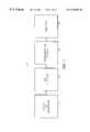
- FIG. 1is a block diagram of an embodiment of the invention
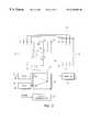
- FIG. 2Ais a schematic diagram of an embodiment of the invention of FIG. 1;
- FIG. 2Bis a graphical representation of the voltages present at each point of the embodiment of the invention shown in FIG. 2A;
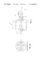
- FIG. 3is a schematic diagram of an embodiment of the fragmentation chamber of FIG. 2;
- FIG. 4is a schematic diagram of an embodiment of the pulsed ion deflector and associated gating potential of FIG. 2;
- FIG. 5is a block diagram of an embodiment of the voltage switching circuits employed in the pulsed ion generator, the timed ion selector, and the timed pulsed extraction referenced in FIG. 2;
- FIG. 6is a graph of the resolution versus mass-to-charge ratio for fragment ions resulting from fragmentation of a hypothetical ion of mass-to-charge ratio 2000 for the embodiment of the invention of FIG. 2;
- FIG. 7is a schematic diagram of an embodiment of an ion guide comprising a stacked plate array that can be positioned in various field free regions of an embodiment of the invention of FIG. 1;
- FIG. 8is a schematic diagram of another embodiment of the invention of FIG. 1;
- FIG. 9is a schematic diagram of an embodiment of a collision cell as the fragmentation chamber for the embodiment of the invention shown in FIG. 8;
- FIG. 9Ais a cross section view of the collision cell in FIG. 9;
- FIG. 10is a schematic diagram of an embodiment of a photodissociation cell as the fragmentation chamber of the embodiment of the invention shown in FIG. 8;
- FIG. 11is a schematic diagram of an embodiment employing collisions of ions with solid or liquid surfaces in the fragmentation chamber of the embodiment of the invention shown in FIG. 8;
- FIG. 12is a schematic diagram of an embodiment of the invention of FIG. 1 wherein a timed ion selector, ion fragmentation chamber and pulsed ion generator are contained within the same vacuum housing.
- a tandem time-of-flight mass spectrometer 10that uses delayed extraction according to the present invention includes: (1) a pulsed ion generator 12 , (2) a timed ion selector 14 in communication with the pulsed ion generator 12 , (3) an ion fragmentor or fragmentation chamber 18 , which is in communication with the timed ion selector 14 , and (4) an ion analyzer 24 .
- a sample to be analyzedis ionized by the pulsed ion generator 12 .
- the ions to be studiedare selected by the timed ion selector 14 , and allowed to pass to the fragmentation chamber 18 .
- the selected ionsare fragmented and allowed to pass to the analyzer 24 .
- the fragmentation chamber 18is designed to function as a delayed extraction source for the analyzer 24 .
- an embodiment of a tandem time-of-flight mass spectrometer 10 using delayed extractionincludes a pulsed ion generator 12 .
- the pulsed ion generatorincludes a laser 27 and a source extraction grid 36 .
- a timed ion selector 14is in communication with the ion generator 12 .
- the ion selector 14comprises a field-free drift tube 16 and a pulsed ion deflector 52 .
- the field-free drift tube 16may include an ion guide as described in connection with FIG. 7 .
- An ion fragmentation chamber 18is in communication with ion selector 14 .
- the ion fragmentation chamber shown in FIG. 2Aincludes a collision cell 44 .
- the fragmentation chamber 18may be any other type of fragmentation chamber known in the art such as a photodissociation chamber or a surface induced dissociation chamber.
- a small aperture 54 at the entrance to the pulsed ion deflector 52allows free passage of the ion beam to the fragmentation chamber 18 , but limits the flow of neutral gas.
- the fragmentation chamber 18is in communication with an ion analyzer 24 .
- a small aperture 58 at the exit of the fragmentation chamber 18allows free passage of the ion beam, but limits the flow of neutral gas.
- a grid plate 53is positioned adjacent to the collision cell 44 and biased to form a field free region 57 .
- the field free region 57may include an ion guide 57 ′ which is shown as a box in FIG. 2 a and which is more fully described in connection with FIG. 7.
- a fragmentor extraction grid 56is positioned adjacent to the grid plate 53 and to an entrance 58 to the analyzer 24 .
- fragmentor extraction grid 56is positioned directly adjacent to the exit aperture, eliminating the grid plate 53 . This embodiment is used for measurements where the fragmentation is substantially completed in the collision cell 44 .
- the analyzer 24includes a second field-free drift tube 16 ′ in communication with an ion mirror 64 .
- the second field-free drift tube 16 ′may include an ion guide as described in connection with FIG. 7.
- a detector 68is positioned to receive the reflected ions.
- the pulsed ion generator 12 and drift tube 16are enclosed in a vacuum housing 20 , which is connected to a vacuum pump (not shown) through a gas outlet 22 .
- the fragmentation chamber 18 and pulsed ion deflector 52are enclosed in vacuum housing 19 , which is connected to a vacuum pump (not shown) through a gas outlet 48 .
- the analyzer 24is enclosed in a vacuum housing 26 , which is connected to a vacuum pump (not shown) through a gas outlet 28 .
- the vacuum pumpmaintains the background pressure of neutral gas in the vacuum housing 20 , 19 , and 26 sufficiently low that collisions of ions with neutral molecules are unlikely to occur.
- a sample 32 to be analyzedis ionized by the pulsed ion generator 12 , which produces a pulse of ions.
- the pulsed ion generator 12employs Matrix Assisted Laser Desorption/Ionization (MALDI).
- MALDIMatrix Assisted Laser Desorption/Ionization
- a laser beam 27 ′impinges upon a sample plate having the sample 32 which has been mixed with a matrix capable of selectively absorbing the wavelength of the incident laser beam 28 .
- the ionsare accelerated by applying an ejection potential between the sample 32 and the source extraction grid 36 and between the source extraction grid 36 and the drift tube 16 .
- the drift tubeis at ground potential.
- the ionstravel through the drift tube with velocities which are nearly proportional to the square root of their charge-to-mass ratio; that is, heavier ions travel more slowly.
- the ionsseparate according to their mass-to-charge ratio with ions of higher mass traveling more slowly than those of lower mass.
- the pulsed ion deflector 52opens for a time window at a predetermined time after ionization. This permits only those ions with the selected mass-to-charge ratios, arriving at the pulsed ion deflector 52 within the predetermined time window during which the pulsed ion deflector 52 is permitting access to the collision cell 44 , to be transmitted. Hence, only predetermined ions, those having the selected mass-to-charge ratio, will be permitted to enter the collision cell 44 by the pulsed ion deflector 52 . Other ions of higher or lower mass are rejected.
- the selected ions entering the collision cell 44collide with the neutral gas entering through inlet 40 .
- the collisionscause the ions to fragment.
- the energy of the collisionsis proportional to a difference in potential between that applied to the sample 32 and the collision cell 44 .
- the pressure of the neutral gas in the collision cell 44is maintained at about 10 ⁇ 3 torr and the pressure in the space surrounding the collision cell 44 is about 10 ⁇ 5 torr.
- Gas diffusing from the collision cell 44 through an ion entrance aperture 46 and ion exit aperture 50is facilitated by a vacuum pump (not shown) connected to a gas outlet 48 .
- a high-speed pulsed valve(not shown) is positioned in gas inlet 40 so as to produce a high pressure pulse of neutral gas during the time when ions arrive at the fragmentation chamber 18 and, for the remainder of the time, the fragmentation chamber 18 is maintained as a vacuum.
- the neutral gasmay be any neutral gas such as helium, air, nitrogen, argon, krypton, or xenon.
- the grid plate 53 and the fragmentor extraction grid 56are biased at substantially the same potential as the collision cell 44 until the fragment ions pass through an aperture 50 ′ in grid plate 53 and enter the nearly field-free region 59 between the grid plate 53 and the extraction grid 56 .
- the potential on grid plate 53is rapidly switched to a high voltage thereby causing the ions to be accelerated.
- the accelerated ionspass through the entrance 58 to the analyzer 24 , into a second field-free drift tube 16 ′, into the ion mirror 64 , and to the detector 68 , which is positioned to receive the reflected ions.
- the time of flight of the ion fragmentsis measured.
- the mass-to-charge ratio of the ion fragmentsis determined from the measured time.
- the mass-to-charge ratiocan be determined with very high resolution by properly choosing the operating parameters so that the fragmentation chamber 18 functions as a delayed extraction source of ion fragments.
- the operating parametersinclude: (1) the delay between the passing of the fragment ions through the aperture 50 ′ in grid plate 53 and the application of the accelerating potential to the grid plate 53 ; and (2) the magnitude of the extraction field between the grid plate 53 and the fragmentor extraction grid 56 .
- grid 53is not used or does not exist. This embodiment is used for measurements where the fragmentation is substantially completed in the collision cell 44 .
- the fragmentor extraction grid 56is biased at substantially the same potential as the collision cell 44 .
- the high voltage connection to the collision cell 44is rapidly switched to a second high voltage supply (not shown) thereby causing the ions to be accelerated.
- the accelerated ionspass through the entrance 58 to the analyzer 24 , into a second field-free drift tube 16 ′, into the ion mirror 64 , and to the detector 68 , which is positioned to receive the reflected ions.
- the time of flight of the ion fragmentsis measured.
- the mass-to-charge ratio of the ion fragmentsis determined from the measured time.
- the mass-to-charge ratiocan be determined with very high resolution by properly choosing the operating parameters so that the fragmentation chamber 18 functions as a delayed extraction source of ion fragments.
- the operating parametersinclude: (1) the predetermined time after the ions exit the collision cell 44 before the high voltage is rapidly switched to the second high voltage; and (2) the magnitude of the extraction field between the collision cell 44 and the fragmentor extraction grid 56 .
- FIG. 2Bdepicts the electric potential experienced by an ion in each portion of the embodiment of the tandem mass spectrometer illustrated in FIG. 2A.
- a voltage 70is applied to the sample 32 and a voltage 71 is applied to extraction grid 36 .
- Voltage 71is approximately equal to voltage 72 .
- a pulse of ionsis formed and emitted into a substantially field-free space 61 between sample 32 and the extraction grid 36 .
- the ionsdepart from the sample 32 with a characteristic velocity distribution which is nearly independent of their mass-to-charge ratio.
- the ionsdrift in the nearly field-free space 61 between the sample 32 and the extraction grid 36 , the ions are distributed in space with the faster ions nearer to the extraction grid 36 and the slower ions nearer to the sample 32 .
- the voltage applied to the sample 32is rapidly switched to higher voltage 72 , thereby establishing an electric field between the sample 32 and the extraction grid 36 .
- the electric field between the sample 32 and the extraction grid 36causes the initially slower ion, which are closest to the sample 32 , to receive a larger acceleration than the initially faster ion.
- the drift tube 16is at a lower potential 73 than the extraction grid 36 and, therefore, a second electric field is established between the extraction grid and the drift tube.
- the voltage 73is at ground potential.
- the ionsare further accelerated by the second electric field.
- the selected focal point 83may be chosen to be at the pulsed ion deflector 52 , at the collision cell 44 , or any other point along the ion trajectory.
- the total time spread at the selected focal point 83 for ions of a specified mass-to-charge ratiois typically about one nanosecond or less. If the selected focal point 83 is chosen to coincide with the location of the pulsed ion deflector 52 , then the pulsed ion deflector 52 gate is opened for a short time interval corresponding to the time of arrival of ions of a selected mass-to-charge ratio and is closed at all other times to reject all other ions.
- the delayed extraction of the present inventionis advantageous because the resolution of ion selection is limited only by properties of the pulsed ion deflector 52 since the time width of the ion packet can be made very small. Thus, high resolution ion selection is possible.
- the pulsed ion deflector 52establishes a transverse electric field that deflect low mass ions until the arrival of ions of a selected mass-to-charge ratio. At which time, the transverse fields are rapidly reduced to zero thereby allowing the selected ions to pass through. After passage of the selected ions, the transverse fields are restored and any higher mass ions are deflected. The selected ions are transmitted undeflected into the fragmentation chamber 18 .
- a voltage 74may be applied to the collision cell 44 to reduce the kinetic energy of the ions before they enter the collision cell 44 through the entrance aperture 46 .
- the energy of the ions in the collision cell 44is determined by their initial potential 81 or 82 relative to voltage 74 plus the kinetic energy associated with their initial velocity.
- the energy with which ions collide with neutral molecules within the collision cell 44can be varied by varying the voltage 74 .
- the voltage 74 applied to the grid plate 53 and the voltage 75 applied to the fragmentor extraction grid 56are equal and, therefore, produce a field-free region between the collision cell 44 and the fragmentor extraction grid 56 .
- the ionsdrift in the field-free region they are distributed in space with the faster ions nearer to the fragmentor extraction grid 56 and the slower ions nearer to the grid plate 53 .
- the voltage applied to the grid plate 53is rapidly switched to a higher voltage 76 thereby establishing an electric field between the grid plate 53 and the fragmentor extraction grid 56 .
- the initially slower ionreceives a larger acceleration than the initially faster ion.
- the grid plate 53 and the collision cell 44are electrically connected so that both are switched simultaneously.
- the voltage applied to the collision cell 44is constant, and only the voltage applied to grid plate 53 is switched.
- the grid plate 53is not used or does not exist. This embodiment is used for measurements where the fragmentation is substantially completed in the collision cell 44 . In this embodiment, there is no field-free region between the collision cell 44 and the fragmentor extraction grid 56 . After a predetermined time delay, the voltage applied to the collision cell 44 is rapidly switched to the higher voltage 76 thereby establishing an electric field between the collision cell 44 and the fragmentor extraction grid 56 . As a result, the initially slower ion receives a larger acceleration than the initially faster ion.
- the ionsare further accelerated in an electric field between the fragmentor extraction grid 56 and the drift tube 16 ′.
- the voltage 77may be at ground potential.
- this focal pointis chosen at or near the entrance 58 to the analyzer 24 .
- the ionstravel through a second field-free region 16 ′ and enter the ion mirror 64 in which the ions are reflected at voltage 79 and eventually strike the detector 68 .
- the voltage 78can be adjusted to refocus the ions, in time, at the detector 68 .
- the fragmentation chamber 18performs as a delayed extraction source for the analyzer 24 and high resolution spectra of fragment ions can be measured.
- FIG. 3is a schematic diagram of an embodiment of the fragmentation chamber 18 of FIG. 2 .
- the collision cell 44includes the gas inlet 40 through which gas is introduced into the collision cell 44 and entrance and exit apertures 46 and 50 , respectively, through which the gas diffuses (arrows D) out from the collision cell 44 .
- These apertures 46 , 50may be covered with highly transparent grids 47 to prevent penetration of external electric fields into the collision cell 44 .
- the gas which diffuses outis drawn off by the vacuum pump attached to the gas outlet 48 (FIG. 2) of the fragmentation chamber 18 .
- uniform electric fieldsare established between the collision cell 44 and entrance aperture 51 to fragmentation chamber 18 , and between fragmentor extraction grid 56 and entrance aperture 58 to the analyzer 24 .
- a high voltage supply 92is connected to extraction grid 56 and resistive voltage divider 53 ′.
- the voltage divider 53 ′is attached to electrically isolated guard rings 55 , which are spaced uniformly in the space between extraction grid 56 and entrance aperture 58 to analyzer 24 , and between the collision cell 44 and the entrance aperture 51 to fragmentation chamber 18 .
- the voltage divider 53 ′is adjusted to provide approximately uniform electric fields in these spaces.
- a high voltage supply 90is electrically connected to the collision cell 44 and is set to voltage 74 (FIG. 2 B).
- the voltage on the grid plate 53is set by a switch 80 which is in electrical communication with high voltage supplies 90 and 91 that are set to voltages 74 and 76 , respectively (FIG. 2 B).
- the switch 80is controlled by a signal from delay generator 87 .
- the delay generator 87provides a control signal to the switch 80 in response to a start signal received from a controller (not shown), which in one embodiment is a digital computer.
- the delayis set so that ions of a selected mass-to-charge ratio pass through the aperture 50 ′ in the grid plate 53 shortly before the switch 80 is activated to switch the high voltage connection to the grid plate 53 from the voltage 74 produced by high voltage supply 90 to the voltage 76 produced by high voltage supply 91
- the pulsed ion deflector 52includes two deflectors in series 100 , 102 located between apertures 51 and 54 covered by highly transparent grids.
- Aperture 54also serves as exit aperture from drift tube 16 and aperture 51 also serves as the entrance aperture 51 to the fragmentation chamber 18 .
- the gridded apertures 51 and 54prevent the fields generated by the deflectors 100 , 102 from propagating beyond the pulsed ion deflector 52 .
- the deflectors 100 , 102are located as close to the plane of the grids over the apertures 51 , 54 as possible without initiating electrical breakdown.
- the deflector 100 closest to the sample 32is operated in a normally closed (NC) or energized configuration in which the electrodes 101 A, 101 B of the deflector 100 have a potential difference between the electrodes.
- the second deflector 102is operated in a normally open (NO) or non-energized configuration in which the electrodes 105 A, 105 B have no voltage difference between them.
- the entrance electrodes 101 A, 101 Bmay be de-energized to open just as the desired ions reach the deflector 100 , while the electrodes 105 A, 105 B of the second deflector 102 are de-energized to close just after the ions of interest pass deflector 102 .
- ions of lower massare rejected by the first deflector 100 and ions of higher mass are rejected by the second deflector 102 .
- Ionsare rejected by deflecting them through a sufficiently large angle to cause them to miss a critical aperture.
- the critical aperturemay coincide with the entrance aperture 46 to the collision cell 44 , to the entrance aperture 58 to the analyzer 24 , or to the detector 68 , whichever subtends the smallest angle of deflection.
- the equations of motion for ions in electric fieldsallows time-of-flight for any ion between any two points along an ion trajectory to be accurately calculated.
- these equationsare particularly tractable, and provided that the voltages, distances, and initial velocities are accurately known, the flight time for any ion between any two points can be accurately calculated.
- the time for an ion to traverse a uniform accelerating fieldis given by the equation:
- v 2is the final velocity after acceleration
- v 1is the initial velocity before acceleration
- tis the time that the ion spends in the field.
- T 2 ⁇ T 1z(V 1 ⁇ V 2 )
- the above equationsprovide exactly the time of flight as a function of mass, charge, potentials, distances, and the initial position and velocity of the ion. If the SI system is used, in which distance is expressed in meters, potentials in volts, masses in kg, charge in coulombs, and time in seconds, then no additional constants are required.
- all of the parametersmay not be known a priori to sufficient accuracy, and it may be necessary in these cases to determine empirically, corrections to the calculated flight times.
- the flight time for an ion of any selected mass-to-charge ratiocan be determined with sufficient accuracy to allow the required time delays between generation of ions in the pulsed ion generator 12 and selection of ions in the timed ion selector 14 or pulsed extraction of ions from the collision cell 44 to be determined accurately.
- a four channel delay generator 162is started by a start pulse 150 which is synchronized with production of ions in the pulsed ion generator 12 .
- the start pulseis generated by detecting a pulse of light from the laser beam 28 .
- a pulse 151is generated by the delay generator 162 , which triggers switch 155 in communication with voltage sources providing voltages 70 and 72 , respectively.
- the switch 155Prior to receiving pulse 151 , the switch 155 is in position 160 connecting the voltage source for voltage 70 to sample 32 . Upon receiving pulse 151 , the switch 155 rapidly moves to position 161 which connects the voltage source for voltage 72 to sample 32 .
- the first delayis chosen so that ions of a selected mass-to-charge ratio produced by the pulsed ion generator 12 are focused in time at a selected point, for example, the pulsed ion deflector 52 .
- pulse 152is generated which triggers switches 156 and 157 .
- switch 156Prior to receiving pulse 152 , switch 156 connects voltage source 120 to deflection plate 101 A, and switch 157 connects voltage source 121 to deflection plate 101 B.
- the switches 156 and 157Upon receiving pulse 152 , the switches 156 and 157 rapidly move to connect both deflection plates 101 A and 101 B to ground.
- switches 158 and 159initially connect electrodes 105 A and 105 B to ground, and in response to delayed pulse 153 , occurring after a third delay period, connect electrodes 105 A and 105 B to voltage sources 122 and 123 , respectively.
- voltage sources 120 and 122supply voltages which are equal and voltage sources 121 and 123 supply voltage sources which are equal in magnitude to the voltage supplied by voltage source 120 but of opposite sign.
- the second delay periodis chosen to correspond to arrival of an ion of selected mass-to-charge ratio at or near the entrance aperture 54 of the pulsed ion deflector 52
- the third delay periodis chosen to correspond to arrival of an ion of selected mass-to-charge ratio at or near the exit aperture 51 of the pulsed ion deflector 52 .
- pulse 154is generated which triggers switch 79 .
- switch 79Prior to receiving pulse 154 , switch 79 connects a voltage source supplying voltage 74 to grid plate 53 , and upon receiving pulse 154 switch 79 rapidly switches to connect voltage source supplying voltage 76 to grid plate 53 .
- the fourth delay periodis chosen to correspond to arrival of an ion of selected mass-to-charge ratio at or near the aperture 50 ′ of grid plate 53 . With proper choice of the fourth delay period, the fragmentation chamber 18 acts as a delayed extraction source for analyzer 24 , and both primary and fragment ions are focused, in time, at the detector 68 .
- Each of the switches 79 , 155 , 156 , 157 , 158 , and 159must be reset to their initial state prior to the next start pulse.
- the time and speed of resetting the switchesis not critical, and it may be accomplished after a fixed delay built into each switch, or a delay pulse from another external delay channel (not shown) may be employed.
- the resolution for fragment ionscan be calculated for any instrumental geometry, such as the embodiment described in FIG. 2, with specified distances, voltages and delay times.
- the plots shown in FIG. 6,correspond to calculations of resolution as a function of fragment mass for an ion of mass-to-charge ratio (m/z) of 2000 produced in the pulsed ion generator 12 with a sample voltage 72 of 20 kilovolts and a collision cell voltage 74 of 19.8 kilovolts corresponding to an ion-neutral collision energy of 200 volts in the laboratory reference frame. (FIGS. 2 A and B).
- the grid plate 53was switched to the higher voltage 76 , which for purposes of this calculation was 25 kilovolts.
- the voltage 75 applied to the fragmentor extraction grid 56was also 19.8 kilovolts so that the region between the extraction grid 56 and the collision cell 44 was field-free.
- the voltage 75 applied to the fragmentor extraction grid 56was 19.9 kilovolts, so that ions emerging from the exit 50 of the collision cell 44 were decelerated by a small amount.
- the latter case 112provides somewhat better resolution at lower fragment mass at the expense of slightly lower theoretical resolution at higher mass.
- some embodiments of this inventioninclude an ion guide 99 positioned in one or more field free regions.
- An ion guidemay be positioned in at least one of the drift tube 16 or 16 ′ or the field free region 57 to increase the transmission of ions.
- ion guidesare known in the art including the wire-in-cylinder type and RF excited multipole lenses consisting of quadrupoles, hexapoles or octupoles.
- One embodiment of the ion guideemploys a stacked ring electrostatic ion guide.
- a stacked ring ion guideincludes a stack of identical plates or rings 108 , 108 ′, each with a central aperture 110 , stacked with uniform space between each pair of rings 108 . Every other ring 108 ′ is connected to a positive voltage supply 109 , and each intervening ring 108 is connected to a negative voltage supply 107 .
- the end plates of the drift tube 16 in which the entrance 106 and exit 54 apertures are locatedare spaced from the ends of stacked ring ion guide, by a distance which is one-half of the distance between the adjacent rings of the guide.
- the ion beamis confined near the axis of the guide.
- FIG. 8is another embodiment of the invention.
- a continuous or a pulsed source of ions 128may be used to supply ions to the pulsed ion generator 12 .
- a beam of ions 129is injected into a field-free space between electrode 130 and extraction grid 36 , and periodically a voltage pulse is applied to electrode 130 to accelerate the ions in a direction orthogonal to that of the initial beam. Ions are further accelerated in a second electric field formed between extraction grid 36 and grid 136 .
- Guard plates 134are connected to a voltage divider (not shown) and may be used to assist in producing a uniform electric field between grids 36 and 136 .
- Ionspass through field-free space 16 and enter fragmentation chamber 18 .
- ionsenter collision cell 44 where they are caused to fragment by collisions with neutral molecules.
- a pulsed ion deflectoris located within the collision cell 44 and the fragmentation chamber 18 functions as a delayed extraction source for analyzer 24 .
- Ions exiting from the fragmentation chamber 18pass through a field-free space 16 ′, are reflected by an ion mirror 64 , re-enter the field-free space 16 ′ and are detected by detector 68 .
- Electrode 130replaces sample 32 (FIG. 2) and pulsed ion deflector 52 is located within collision cell 44 (FIG. 8 ).
- a beam of ions 129 produced in continuous ion source 128enters the space between electrode 130 and extraction grid 36 between points 81 and 82 .
- the voltage 70 on electrode 130is equal to voltage 71 on extraction grid 36
- the electrode 130is switched to voltage 72 to extract ions.
- the voltage difference between 70 and 72is chosen so that ions in the beam are focused, in time, at or near the exit from the collision cell 44 .
- the voltage 71 on extraction grid 36is ground potential
- voltage 73 on drift tube 16 and 16 ′is a voltage opposite in sign to that of ions of interest.
- the energy of the ions in the collision cell 44is determined by their initial potential 81 or 82 relative to voltage 74 plus the kinetic energy associated with their initial velocity.
- the energy with which ions collide with neutral molecules within the collision cell 44can be varied by varying the voltage 74 .
- the voltage 71 and the voltage 74are at ground potential.
- the extraction field between collision cell 44 and fragmentor extraction grid 56is formed by switching voltage 75 , initially at or near ground, to a lower voltage.
- a pulsed ion deflector 52is located within the collision cell 44 . Ions from the pulsed ion generator 12 (FIG. 8) are focused at or near the exit 104 of collision cell 44 . At the time that a pulse of ions with a selected mass-to-charge ratio arrive at or near the entrance 103 to collision cell 44 , pulsed ion deflector 100 is de-energized to allow selected ions to pass undeflected. At the time that the pulse of ions with selected mass-to-charge ratio arrive at or near exit 104 to collision cell 44 , pulsed ion deflector 102 is energized to deflect ions of higher mass, which arrive later at pulsed deflector 102 .
- ions with lower mass-to-charge ratioare deflected by pulsed ion deflector 100 and ions with higher mass-to-charge ratio are deflected by pulsed ion deflector 102 , and ions within the selected mass-to-charge ratio range are transmitted undeflected.
- the voltages applied to the pulsed ion deflectors 100 and 102are adjusted so that deflected ions and any fragments produced within collision cell are not transmitted through a critical aperture, which in this embodiment, is the entrance aperture 58 to the analyzer 24 .
- the beam from the continuous ion source 128is cylindrical in cross section and well collimated so that velocity components in the direction perpendicular to the axis of the beam are very small.
- the pulsed beam 39 generated by the pulsed ion generator 12is relatively wide in the direction of ion travel from the continuous ion source 128 , but is narrow in orthogonal directions. That is, if the beam direction is along the x-axis, then the beam widths orthogonal to this will be narrow.
- the widths of the apertures 36 , 136 , 138 , 103 , 104 , 56 , and 142must be wide enough in the plane defined by directions of the continuous beam 129 and the pulsed beam 32 to allow essentially the entire pulsed beam to be transmitted, but may be narrow in the direction perpendicular to this plane.
- FIG. 9Ashows a cross section through the collision cell 44 , wherein the exit aperture 104 is 25 mm long in the direction parallel to the beam from the continuous ion source 128 , and is 1.5 mm in the direction orthogonal to the plane defined by the beam from the continuous ion source 128 and the pulsed beam 39 .
- the other apertures 36 , 136 , 138 , 103 , 56 , 142may have similar dimensions.
- the initial velocity of the continuous ion beam 129adds vectorially to the velocity imparted by acceleration in the pulsed ion generator 12 .
- the trajectory of the pulsed ion beam 39is at a small angle relative to the direction of acceleration and the slits are offset along their long direction so that the center of the pulsed ion beam 39 passes near the center of each aperture.
- one embodiment of the inventionemploys a photodissociation cell 152 in fragmentation chamber 18 .
- the photodissociation cellis similar to the collision cell 44 , but instead of an inflow of neutral gas through inlet 40 , a pulsed laser beam 150 is directed into the cell through aperture or window 160 and exits from the cell through aperture or window 161 .
- the laser pulseis synchronized with the start pulse and a delay generator (not shown) so that the laser pulse arrives at the center of the photodissociation cell at the same time as the ion pulse of a selected mass-to-charge ratio.
- the wavelength of the laseris chosen so that the ion of interest absorbs energy at this wavelength.
- a quadrupled Nd: YAG laser having a wavelength of the laser light of 266 nmis used.
- an excimer laser having a wavelength of 193 nmis used. Any wavelength of radiation can be employed provided that it is absorbed by the ion of interest.
- the ion of interestis energized by absorption of one or more photons from the pulsed laser beam 150 and is caused to fragment. The fragments are analyzed with the fragmentation chamber 18 acting as a delayed extraction source for analyzer 24 , as described in detail above.
- the photodissociation cell 152is also equipped with pulsed ion deflectors 100 and 102 to prevent ions of mass-to-charge ratios different from the selected ions from being transmitted to the analyzer 24 .
- one embodiment of the inventionemploys a surface-induced dissociation cell 154 in fragmentation chamber 18 .
- ions of interestare selected by pulsed ion deflector 52 and ions of other mass-to-charge ratios are deflected so that they do not enter the surface-induced dissociation cell 154 .
- a potential differenceis applied between electrodes 158 and 156 to deflect selected ions so that they collide with the surface 159 of electrode 156 at a grazing angle of incidence. Ions are energized by collisions with the surface 159 and caused to fragment.
- the surface 159is coated with a high molecular weight, relatively involatile liquid, such as a perfluorinated, ether to facilitate fragmentation or to reduce the probability of charge exchange with the surface.
- a high molecular weight, relatively involatile liquidsuch as a perfluorinated, ether to facilitate fragmentation or to reduce the probability of charge exchange with the surface.
- the fragment ionsare analyzed with the fragmentation chamber 18 acting as delayed extraction source for analyzer 24 .
- the timed ion selector 14 and ion fragmentation chamber 18are enclosed in the same vacuum housing 20 as the pulsed ion generator 12 .
- a pulsed ion extractorcomprising the grid plate 53 and the fragmentor extraction grid 56 is located in vacuum housing 26 enclosing the analyzer 24 .
- a small aperture 58located in the nearly field-free space 57 between the fragmentation chamber 18 and grid plate 53 allows free passage of the ion beam but limits the flow of neutral gas.
- an einzel lensis located between the pulsed ion generator 12 and the timed ion selector 14 to focus ions through aperture 58 .
- vacuum housing 19FIG. 2
- its associated vacuum pumpare not required.
- collision cell 44 within fragmentation chamber 18is connected to ground potential as is the fragmentor extraction grid 56 .
- Grid plate 53is also held initially at ground, and switched to high voltage after ions of interest have reached the nearly field-free space 59 between the grid plate 53 and the fragmentor extraction grid 56 .
Landscapes
- Chemical & Material Sciences (AREA)
- Analytical Chemistry (AREA)
- Other Investigation Or Analysis Of Materials By Electrical Means (AREA)
- Electron Tubes For Measurement (AREA)
Abstract
Description
Claims (37)
Priority Applications (8)
| Application Number | Priority Date | Filing Date | Title |
|---|---|---|---|
| US09/233,703US6348688B1 (en) | 1998-02-06 | 1999-01-19 | Tandem time-of-flight mass spectrometer with delayed extraction and method for use |
| DE69942413TDE69942413D1 (en) | 1998-02-06 | 1999-02-05 | TANDEM FLIGHT-TIME MASS SPECTROMETER WITH DELAYED EXTRACTION AND METHOD |
| PCT/US1999/002599WO1999040610A2 (en) | 1998-02-06 | 1999-02-05 | A tandem time-of-flight mass spectrometer with delayed extraction and method for use |
| EP99906780AEP1060502B1 (en) | 1998-02-06 | 1999-02-05 | A tandem time-of-flight mass spectrometer with delayed extraction and method for use |
| JP2000530930AJP2002503020A (en) | 1998-02-06 | 1999-02-05 | Tandem time-of-flight mass spectrometer with delay drawer and method of use |
| US10/023,203US6770870B2 (en) | 1998-02-06 | 2001-12-17 | Tandem time-of-flight mass spectrometer with delayed extraction and method for use |
| JP2003126506AJP4023738B2 (en) | 1998-02-06 | 2003-05-01 | Tandem time-of-flight mass spectrometer with delayed drawer and method of use |
| US10/910,246US20050116162A1 (en) | 1998-02-06 | 2004-08-02 | Tandem time-of-flight mass spectrometer with delayed extraction and method for use |
Applications Claiming Priority (2)
| Application Number | Priority Date | Filing Date | Title |
|---|---|---|---|
| US2014298A | 1998-02-06 | 1998-02-06 | |
| US09/233,703US6348688B1 (en) | 1998-02-06 | 1999-01-19 | Tandem time-of-flight mass spectrometer with delayed extraction and method for use |
Related Parent Applications (1)
| Application Number | Title | Priority Date | Filing Date |
|---|---|---|---|
| US2014298AContinuation-In-Part | 1998-02-06 | 1998-02-06 |
Related Child Applications (1)
| Application Number | Title | Priority Date | Filing Date |
|---|---|---|---|
| US10/023,203ContinuationUS6770870B2 (en) | 1998-02-06 | 2001-12-17 | Tandem time-of-flight mass spectrometer with delayed extraction and method for use |
Publications (1)
| Publication Number | Publication Date |
|---|---|
| US6348688B1true US6348688B1 (en) | 2002-02-19 |
Family
ID=26693086
Family Applications (3)
| Application Number | Title | Priority Date | Filing Date |
|---|---|---|---|
| US09/233,703Expired - LifetimeUS6348688B1 (en) | 1998-02-06 | 1999-01-19 | Tandem time-of-flight mass spectrometer with delayed extraction and method for use |
| US10/023,203Expired - LifetimeUS6770870B2 (en) | 1998-02-06 | 2001-12-17 | Tandem time-of-flight mass spectrometer with delayed extraction and method for use |
| US10/910,246AbandonedUS20050116162A1 (en) | 1998-02-06 | 2004-08-02 | Tandem time-of-flight mass spectrometer with delayed extraction and method for use |
Family Applications After (2)
| Application Number | Title | Priority Date | Filing Date |
|---|---|---|---|
| US10/023,203Expired - LifetimeUS6770870B2 (en) | 1998-02-06 | 2001-12-17 | Tandem time-of-flight mass spectrometer with delayed extraction and method for use |
| US10/910,246AbandonedUS20050116162A1 (en) | 1998-02-06 | 2004-08-02 | Tandem time-of-flight mass spectrometer with delayed extraction and method for use |
Country Status (4)
| Country | Link |
|---|---|
| US (3) | US6348688B1 (en) |
| EP (1) | EP1060502B1 (en) |
| JP (2) | JP2002503020A (en) |
| WO (1) | WO1999040610A2 (en) |
Cited By (68)
| Publication number | Priority date | Publication date | Assignee | Title |
|---|---|---|---|---|
| US6441369B1 (en)* | 2000-11-15 | 2002-08-27 | Perseptive Biosystems, Inc. | Tandem time-of-flight mass spectrometer with improved mass resolution |
| US20020117616A1 (en)* | 1998-02-06 | 2002-08-29 | Vestal Marvin L. | Tandem time-of-flight mass spectrometer with delayed extraction and method for use |
| US20020145109A1 (en)* | 2001-04-10 | 2002-10-10 | Science & Engineering Services, Inc. | Time-of-flight/ion trap mass spectrometer, a method, and a computer program product to use the same |
| US20030006370A1 (en)* | 2001-06-25 | 2003-01-09 | Bateman Robert Harold | Mass spectrometer |
| US6518568B1 (en)* | 1999-06-11 | 2003-02-11 | Johns Hopkins University | Method and apparatus of mass-correlated pulsed extraction for a time-of-flight mass spectrometer |
| US6534764B1 (en)* | 1999-06-11 | 2003-03-18 | Perseptive Biosystems | Tandem time-of-flight mass spectrometer with damping in collision cell and method for use |
| US6545268B1 (en)* | 2000-04-10 | 2003-04-08 | Perseptive Biosystems | Preparation of ion pulse for time-of-flight and for tandem time-of-flight mass analysis |
| US20030175844A1 (en)* | 2002-03-12 | 2003-09-18 | Nadler Timothy K. | Method and apparatus for the identification and quantification of biomolecules |
| US20030213901A1 (en)* | 2002-03-28 | 2003-11-20 | Covey Thomas R. | Method and system for high-throughput quantitation of small molecules using laser desorption and multiple-reaction-monitoring |
| WO2003086589A3 (en)* | 2002-04-10 | 2003-12-18 | Univ Johns Hopkins | Miniaturized sample scanning mass analyzer |
| US20040021069A1 (en)* | 2002-04-23 | 2004-02-05 | Thermo Electron Corporation | Spectroscopic analyser for surface analysis, and method therefor |
| WO2004019035A2 (en) | 2002-08-22 | 2004-03-04 | Applera Corporation | Method for characterizing biomolecules utilizing a result driven strategy |
| US6707037B2 (en)* | 2001-05-25 | 2004-03-16 | Analytica Of Branford, Inc. | Atmospheric and vacuum pressure MALDI ion source |
| US6723983B2 (en)* | 2001-03-01 | 2004-04-20 | Bruker Daltonik Gmbh | High throughput of laser desorption mass spectra in time-of-flight mass spectrometers |
| US20040149900A1 (en)* | 2001-05-29 | 2004-08-05 | Makarov Alexander Alekseevich | Time of flight mass spectrometer and multiple detector therefor |
| US20040183006A1 (en)* | 2003-03-17 | 2004-09-23 | Reilly James P. | Method and apparatus for controlling position of a laser of a MALDI mass spectrometer |
| US20040183010A1 (en)* | 2003-03-17 | 2004-09-23 | Reilly James P. | Method and apparatus for mass spectrometric analysis of samples |
| US20040183009A1 (en)* | 2003-03-17 | 2004-09-23 | Reilly James P. | MALDI mass spectrometer having a laser steering assembly and method of operating the same |
| US6864479B1 (en) | 1999-09-03 | 2005-03-08 | Thermo Finnigan, Llc | High dynamic range mass spectrometer |
| US20050092916A1 (en)* | 2003-10-31 | 2005-05-05 | Vestal Marvin L. | Ion source and methods for MALDI mass spectrometry |
| US20050153456A1 (en)* | 2003-11-26 | 2005-07-14 | Applera Corporation | Analysis of mass spectral data in the quiet zones |
| GB2413213A (en)* | 2004-04-13 | 2005-10-19 | Kratos Analytical Ltd | An ion selector with a plurality of deflection zones |
| US20050285031A1 (en)* | 2002-03-28 | 2005-12-29 | Mds Sciex Inc. | Method and system for high-throughput quantitation using laser desorption and multiple-reaction-monitoring |
| US20060009915A1 (en)* | 2000-12-26 | 2006-01-12 | Institute Of Systems Biology | Rapid and quantitative proteome analysis and related methods |
| US20060071159A1 (en)* | 2004-10-06 | 2006-04-06 | Yuichiro Hashimoto | Ion-mobility spectrometer and ion-mobility analysis method |
| US20060108521A1 (en)* | 2004-09-20 | 2006-05-25 | Bruker Daltonik Gmbh | Daughter ion spectra with time-of-flight mass spectrometers |
| US20060151690A1 (en)* | 1998-09-16 | 2006-07-13 | Philip Marriott | Means for removing unwanted ions from an ion transport system and mass spectrometer |
| US20060255289A1 (en)* | 2005-05-13 | 2006-11-16 | Cygan Thomas R | Sample handling mechanisms and methods for mass spectometry |
| US20060255256A1 (en)* | 2005-05-13 | 2006-11-16 | Hayden Kevin M | Mass analyzer systems and methods for their operation |
| US20060255259A1 (en)* | 2005-04-20 | 2006-11-16 | Bruker Daltonik Gmbh | Tandem mass spectrometry with feedback control |
| US20060273252A1 (en)* | 2005-05-13 | 2006-12-07 | Mds Inc. | Methods of operating ion optics for mass spectrometry |
| US7405397B2 (en) | 2002-03-28 | 2008-07-29 | Mds Sciex Inc. | Laser desorption ion source with ion guide coupling for ion mass spectroscopy |
| US20080272286A1 (en)* | 2007-05-01 | 2008-11-06 | Vestal Marvin L | Vacuum Housing System for MALDI-TOF Mass Spectrometry |
| US20080272290A1 (en)* | 2007-05-01 | 2008-11-06 | Vestal Marvin L | Reflector TOF With High Resolution and Mass Accuracy for Peptides and Small Molecules |
| US20080272291A1 (en)* | 2007-05-01 | 2008-11-06 | Vestal Marvin L | Tof-tof with high resolution precursor selection and multiplexed ms-ms |
| US20080272289A1 (en)* | 2007-05-01 | 2008-11-06 | Vestal Marvin L | Linear tof geometry for high sensitivity at high mass |
| US20080272293A1 (en)* | 2007-05-01 | 2008-11-06 | Vestal Marvin L | Reversed Geometry MALDI TOF |
| US20080272287A1 (en)* | 2007-05-01 | 2008-11-06 | Vestal Marvin L | High Performance Low Cost MALDI MS-MS |
| WO2008157188A1 (en)* | 2007-06-14 | 2008-12-24 | Quest Diagnostics Investments Incorporated | Mass spectrometry method for measuring vitamin b6 in body fluid |
| US20090065689A1 (en)* | 2002-07-24 | 2009-03-12 | Micromass Uk Ltd | Mass analysis using alternating fragmentation modes |
| US20090194679A1 (en)* | 2008-01-31 | 2009-08-06 | Agilent Technologies, Inc. | Methods and apparatus for reducing noise in mass spectrometry |
| US20090250605A1 (en)* | 2006-07-03 | 2009-10-08 | David Scigocki | Method and system of tandem mass spectrometry without primary mass selection for multicharged ions |
| JP2014225339A (en)* | 2013-05-15 | 2014-12-04 | 株式会社島津製作所 | Time-of-flight mass spectrometer |
| USRE45553E1 (en) | 2002-05-13 | 2015-06-09 | Thermo Fisher Scientific Inc. | Mass spectrometer and mass filters therefor |
| US20150211924A1 (en)* | 2010-11-12 | 2015-07-30 | Industry-Academic Cooperation Foundation Yonsei University | Device for preventing intensity reduction of optical signal, optical emission spectrometer, optical instrument, and mass spectrometer including the same |
| US9984863B2 (en) | 2014-03-31 | 2018-05-29 | Leco Corporation | Multi-reflecting time-of-flight mass spectrometer with axial pulsed converter |
| US10557823B2 (en)* | 2014-10-14 | 2020-02-11 | Smiths Detection-Watford Limited | Ion filter for mass spectrometer |
| US20200258729A1 (en)* | 2015-03-06 | 2020-08-13 | Micromass Uk Limited | Collision Surface for Improved Ionisation |
| US10777397B2 (en) | 2015-03-06 | 2020-09-15 | Micromass Uk Limited | Inlet instrumentation for ion analyser coupled to rapid evaporative ionisation mass spectrometry (“REIMS”) device |
| US10777398B2 (en) | 2015-03-06 | 2020-09-15 | Micromass Uk Limited | Spectrometric analysis |
| US10916415B2 (en) | 2015-03-06 | 2021-02-09 | Micromass Uk Limited | Liquid trap or separator for electrosurgical applications |
| US10978284B2 (en) | 2015-03-06 | 2021-04-13 | Micromass Uk Limited | Imaging guided ambient ionisation mass spectrometry |
| US11022118B2 (en) | 2016-04-27 | 2021-06-01 | Mark W. Wood | Concentric vane compressor |
| US11031222B2 (en) | 2015-03-06 | 2021-06-08 | Micromass Uk Limited | Chemically guided ambient ionisation mass spectrometry |
| US11031223B2 (en) | 2015-09-29 | 2021-06-08 | Micromass Uk Limited | Capacitively coupled REIMS technique and optically transparent counter electrode |
| US11037774B2 (en) | 2015-03-06 | 2021-06-15 | Micromass Uk Limited | Physically guided rapid evaporative ionisation mass spectrometry (“REIMS”) |
| US11139156B2 (en) | 2015-03-06 | 2021-10-05 | Micromass Uk Limited | In vivo endoscopic tissue identification tool |
| US11239066B2 (en) | 2015-03-06 | 2022-02-01 | Micromass Uk Limited | Cell population analysis |
| US11264223B2 (en) | 2015-03-06 | 2022-03-01 | Micromass Uk Limited | Rapid evaporative ionisation mass spectrometry (“REIMS”) and desorption electrospray ionisation mass spectrometry (“DESI-MS”) analysis of swabs and biopsy samples |
| US11270876B2 (en) | 2015-03-06 | 2022-03-08 | Micromass Uk Limited | Ionisation of gaseous samples |
| US11282688B2 (en) | 2015-03-06 | 2022-03-22 | Micromass Uk Limited | Spectrometric analysis of microbes |
| US11289320B2 (en) | 2015-03-06 | 2022-03-29 | Micromass Uk Limited | Tissue analysis by mass spectrometry or ion mobility spectrometry |
| US11339786B2 (en) | 2016-11-07 | 2022-05-24 | Mark W. Wood | Scroll compressor with circular surface terminations |
| US11367605B2 (en) | 2015-03-06 | 2022-06-21 | Micromass Uk Limited | Ambient ionization mass spectrometry imaging platform for direct mapping from bulk tissue |
| US11454611B2 (en) | 2016-04-14 | 2022-09-27 | Micromass Uk Limited | Spectrometric analysis of plants |
| US11480178B2 (en) | 2016-04-27 | 2022-10-25 | Mark W. Wood | Multistage compressor system with intercooler |
| CN115777061A (en)* | 2020-05-27 | 2023-03-10 | 史密斯探测-沃特福特有限公司 | Ion shutter, method of controlling ion shutter, and detection method and apparatus |
| US11686309B2 (en) | 2016-11-07 | 2023-06-27 | Mark W. Wood | Scroll compressor with circular surface terminations |
Families Citing this family (66)
| Publication number | Priority date | Publication date | Assignee | Title |
|---|---|---|---|---|
| KR20020022653A (en) | 1999-04-29 | 2002-03-27 | 사이퍼젠 바이오시스템스, 인코오포레이티드 | Sample holder with hydrophobic coating for gas phase mass spectrometers |
| AU2001243328A1 (en)* | 2000-02-29 | 2001-09-12 | The Texas A And M University System | A periodic field focusing ion mobility spectrometer |
| GB0006046D0 (en) | 2000-03-13 | 2000-05-03 | Univ Warwick | Time of flight mass spectrometry apparatus |
| CA2425434A1 (en)* | 2000-10-11 | 2002-04-18 | Tina Morris | Methods for characterizing molecular interactions using affinity capture tandem mass spectrometry |
| GB2390935A (en) | 2002-07-16 | 2004-01-21 | Anatoli Nicolai Verentchikov | Time-nested mass analysis using a TOF-TOF tandem mass spectrometer |
| US7196324B2 (en) | 2002-07-16 | 2007-03-27 | Leco Corporation | Tandem time of flight mass spectrometer and method of use |
| US6914242B2 (en)* | 2002-12-06 | 2005-07-05 | Agilent Technologies, Inc. | Time of flight ion trap tandem mass spectrometer system |
| US6933497B2 (en)* | 2002-12-20 | 2005-08-23 | Per Septive Biosystems, Inc. | Time-of-flight mass analyzer with multiple flight paths |
| US20060138316A1 (en)* | 2003-01-28 | 2006-06-29 | Robert Seydoux | Time-of-flight mass spectrometer |
| US7825374B2 (en)* | 2003-02-21 | 2010-11-02 | The Johns Hopkins University | Tandem time-of-flight mass spectrometer |
| JP4214925B2 (en)* | 2004-02-26 | 2009-01-28 | 株式会社島津製作所 | Mass spectrometer |
| US7157701B2 (en)* | 2004-05-20 | 2007-01-02 | Mississippi State University Research And Technology Corporation | Compact time-of-flight mass spectrometer |
| GB0427634D0 (en)* | 2004-12-17 | 2005-01-19 | Micromass Ltd | Mass spectrometer |
| JP4688504B2 (en)* | 2005-01-11 | 2011-05-25 | 日本電子株式会社 | Tandem time-of-flight mass spectrometer |
| US7176454B2 (en)* | 2005-02-09 | 2007-02-13 | Applera Corporation | Ion sources for mass spectrometry |
| US20060262295A1 (en)* | 2005-05-20 | 2006-11-23 | Vistec Semiconductor Systems Gmbh | Apparatus and method for inspecting a wafer |
| KR100691404B1 (en) | 2005-09-09 | 2007-03-09 | 한국원자력연구소 | Nonlinear Ion Accelerator and Mass Spectrometry Using the Same |
| US7375569B2 (en)* | 2005-09-21 | 2008-05-20 | Leco Corporation | Last stage synchronizer system |
| JP4997384B2 (en)* | 2005-10-21 | 2012-08-08 | 独立行政法人産業技術総合研究所 | Mass spectrometry method |
| JP4902230B2 (en)* | 2006-03-09 | 2012-03-21 | 株式会社日立ハイテクノロジーズ | Mass spectrometer |
| US7491931B2 (en)* | 2006-05-05 | 2009-02-17 | Applera Corporation | Power supply regulation using a feedback circuit comprising an AC and DC component |
| GB0612503D0 (en) | 2006-06-23 | 2006-08-02 | Micromass Ltd | Mass spectrometer |
| US7534996B2 (en)* | 2006-06-30 | 2009-05-19 | Wayne State University | Velocity imaging tandem mass spectrometer |
| JP2008282571A (en)* | 2007-05-08 | 2008-11-20 | Shimadzu Corp | Time-of-flight mass spectrometer |
| DE102007024857B4 (en)* | 2007-05-29 | 2017-11-02 | Bruker Daltonik Gmbh | Imaging mass spectrometry for small molecules in flat samples |
| JP4994119B2 (en)* | 2007-06-01 | 2012-08-08 | 日本電子株式会社 | Tandem time-of-flight mass spectrometer |
| JP4922900B2 (en)* | 2007-11-13 | 2012-04-25 | 日本電子株式会社 | Vertical acceleration time-of-flight mass spectrometer |
| JP5226292B2 (en)* | 2007-12-25 | 2013-07-03 | 日本電子株式会社 | Tandem time-of-flight mass spectrometry |
| JP5069158B2 (en)* | 2008-03-21 | 2012-11-07 | 日本電子株式会社 | Tandem time-of-flight mass spectrometer |
| JP5220574B2 (en)* | 2008-12-09 | 2013-06-26 | 日本電子株式会社 | Tandem time-of-flight mass spectrometer |
| US8461521B2 (en)* | 2010-12-14 | 2013-06-11 | Virgin Instruments Corporation | Linear time-of-flight mass spectrometry with simultaneous space and velocity focusing |
| US8847155B2 (en) | 2009-08-27 | 2014-09-30 | Virgin Instruments Corporation | Tandem time-of-flight mass spectrometry with simultaneous space and velocity focusing |
| US8674292B2 (en) | 2010-12-14 | 2014-03-18 | Virgin Instruments Corporation | Reflector time-of-flight mass spectrometry with simultaneous space and velocity focusing |
| US8035081B2 (en)* | 2009-09-30 | 2011-10-11 | The United States Of America As Represented By The Administrator Of The National Aeronautics And Space Administration | High precision electric gate for time-of-flight ion mass spectrometers |
| US8399828B2 (en)* | 2009-12-31 | 2013-03-19 | Virgin Instruments Corporation | Merged ion beam tandem TOF-TOF mass spectrometer |
| JP5555582B2 (en)* | 2010-09-22 | 2014-07-23 | 日本電子株式会社 | Tandem time-of-flight mass spectrometry and apparatus |
| GB201110662D0 (en) | 2011-06-23 | 2011-08-10 | Thermo Fisher Scient Bremen | Targeted analysis for tandem mass spectrometry |
| WO2013098599A1 (en)* | 2011-12-29 | 2013-07-04 | Dh Technologies Development Pte. Ltd. | System and method for quantitation in mass spectrometry |
| WO2013171556A1 (en)* | 2012-05-18 | 2013-11-21 | Dh Technologies Development Pte. Ltd. | Modulation of instrument resolution dependant upon the complexity of a previous scan |
| GB2555328B (en) | 2012-06-18 | 2018-08-29 | Leco Corp | Multiplexed mass spectral analysis using non-redundant sampling |
| JP5993677B2 (en)* | 2012-09-14 | 2016-09-14 | 日本電子株式会社 | Time-of-flight mass spectrometer and control method of time-of-flight mass spectrometer |
| WO2014045093A1 (en)* | 2012-09-18 | 2014-03-27 | Dh Technologies Development Pte. Ltd. | Systems and methods for acquiring data for mass spectrometry images |
| JP6084815B2 (en)* | 2012-10-30 | 2017-02-22 | 日本電子株式会社 | Tandem time-of-flight mass spectrometer |
| EP2936545B1 (en)* | 2012-12-20 | 2019-10-30 | DH Technologies Development Pte. Ltd. | Interlacing to improve sampling of data when ramping parameters |
| US8735810B1 (en) | 2013-03-15 | 2014-05-27 | Virgin Instruments Corporation | Time-of-flight mass spectrometer with ion source and ion detector electrically connected |
| WO2015026727A1 (en) | 2013-08-19 | 2015-02-26 | Virgin Instruments Corporation | Ion optical system for maldi-tof mass spectrometer |
| CN108475634B (en)* | 2016-01-15 | 2022-08-12 | 玛特森技术公司 | Variable Pattern Separation Grid for Plasma Chambers |
| GB201613988D0 (en) | 2016-08-16 | 2016-09-28 | Micromass Uk Ltd And Leco Corp | Mass analyser having extended flight path |
| GB2567794B (en) | 2017-05-05 | 2023-03-08 | Micromass Ltd | Multi-reflecting time-of-flight mass spectrometers |
| GB2563571B (en) | 2017-05-26 | 2023-05-24 | Micromass Ltd | Time of flight mass analyser with spatial focussing |
| WO2019030471A1 (en) | 2017-08-06 | 2019-02-14 | Anatoly Verenchikov | Ion guide within pulsed converters |
| EP3662503A1 (en) | 2017-08-06 | 2020-06-10 | Micromass UK Limited | Ion injection into multi-pass mass spectrometers |
| WO2019030473A1 (en) | 2017-08-06 | 2019-02-14 | Anatoly Verenchikov | Fields for multi-reflecting tof ms |
| US11211238B2 (en) | 2017-08-06 | 2021-12-28 | Micromass Uk Limited | Multi-pass mass spectrometer |
| US11817303B2 (en) | 2017-08-06 | 2023-11-14 | Micromass Uk Limited | Accelerator for multi-pass mass spectrometers |
| WO2019030472A1 (en) | 2017-08-06 | 2019-02-14 | Anatoly Verenchikov | Ion mirror for multi-reflecting mass spectrometers |
| EP3662502A1 (en) | 2017-08-06 | 2020-06-10 | Micromass UK Limited | Printed circuit ion mirror with compensation |
| AU2019220546A1 (en)* | 2018-02-13 | 2020-08-27 | Biomerieux, Inc. | Methods for confirming charged-particle generation in an instrument, and related instruments |
| JP6808669B2 (en)* | 2018-03-14 | 2021-01-06 | 日本電子株式会社 | Mass spectrometer |
| GB201806507D0 (en) | 2018-04-20 | 2018-06-06 | Verenchikov Anatoly | Gridless ion mirrors with smooth fields |
| GB201807626D0 (en) | 2018-05-10 | 2018-06-27 | Micromass Ltd | Multi-reflecting time of flight mass analyser |
| GB201807605D0 (en) | 2018-05-10 | 2018-06-27 | Micromass Ltd | Multi-reflecting time of flight mass analyser |
| GB201808530D0 (en) | 2018-05-24 | 2018-07-11 | Verenchikov Anatoly | TOF MS detection system with improved dynamic range |
| GB201810573D0 (en) | 2018-06-28 | 2018-08-15 | Verenchikov Anatoly | Multi-pass mass spectrometer with improved duty cycle |
| GB201901411D0 (en) | 2019-02-01 | 2019-03-20 | Micromass Ltd | Electrode assembly for mass spectrometer |
| GB201903779D0 (en) | 2019-03-20 | 2019-05-01 | Micromass Ltd | Multiplexed time of flight mass spectrometer |
Citations (19)
| Publication number | Priority date | Publication date | Assignee | Title |
|---|---|---|---|---|
| US4731533A (en) | 1986-10-15 | 1988-03-15 | Vestec Corporation | Method and apparatus for dissociating ions by electron impact |
| US5032722A (en) | 1989-06-23 | 1991-07-16 | Bruker Franzen Analytik Gmbh | MS-MS time-of-flight mass spectrometer |
| US5118937A (en) | 1989-08-22 | 1992-06-02 | Finnigan Mat Gmbh | Process and device for the laser desorption of an analyte molecular ions, especially of biomolecules |
| US5144127A (en) | 1991-08-02 | 1992-09-01 | Williams Evan R | Surface induced dissociation with reflectron time-of-flight mass spectrometry |
| US5202563A (en) | 1991-05-16 | 1993-04-13 | The Johns Hopkins University | Tandem time-of-flight mass spectrometer |
| US5206508A (en) | 1990-10-18 | 1993-04-27 | Unisearch Limited | Tandem mass spectrometry systems based on time-of-flight analyzer |
| US5233189A (en) | 1991-03-04 | 1993-08-03 | Hermann Wollnik | Time-of-flight mass spectrometer as the second stage for a tandem mass spectrometer |
| US5464985A (en) | 1993-10-01 | 1995-11-07 | The Johns Hopkins University | Non-linear field reflectron |
| US5625184A (en) | 1995-05-19 | 1997-04-29 | Perseptive Biosystems, Inc. | Time-of-flight mass spectrometry analysis of biomolecules |
| US5654545A (en) | 1995-09-19 | 1997-08-05 | Bruker-Franzen Analytik Gmbh | Mass resolution in time-of-flight mass spectrometers with reflectors |
| US5696375A (en) | 1995-11-17 | 1997-12-09 | Bruker Analytical Instruments, Inc. | Multideflector |
| WO1997048120A1 (en) | 1996-06-10 | 1997-12-18 | Hd Technologies Limited | Time-of-flight mass spectrometer |
| US5734161A (en) | 1995-12-01 | 1998-03-31 | Bruker-Franzen Analytik, Gmbh | Method for time-of-flight mass spectrometry of daughter ions |
| US5744797A (en) | 1995-11-22 | 1998-04-28 | Bruker Analytical Instruments, Inc. | Split-field interface |
| US5753909A (en) | 1995-11-17 | 1998-05-19 | Bruker Analytical Systems, Inc. | High resolution postselector for time-of-flight mass spectrometery |
| US5854484A (en) | 1996-08-01 | 1998-12-29 | Bergmann; Thorald Horst | Collision cell with integrated ion selector for MS/MS-time-of flight mass-spectrometer |
| US5854485A (en) | 1996-08-01 | 1998-12-29 | Bergmann; Thorald Horst | MS/MS time-of-flight mass-spectrometer with collision cell |
| US6011259A (en)* | 1995-08-10 | 2000-01-04 | Analytica Of Branford, Inc. | Multipole ion guide ion trap mass spectrometry with MS/MSN analysis |
| US6040575A (en)* | 1998-01-23 | 2000-03-21 | Analytica Of Branford, Inc. | Mass spectrometry from surfaces |
Family Cites Families (2)
| Publication number | Priority date | Publication date | Assignee | Title |
|---|---|---|---|---|
| US6348688B1 (en)* | 1998-02-06 | 2002-02-19 | Perseptive Biosystems | Tandem time-of-flight mass spectrometer with delayed extraction and method for use |
| JP3662595B2 (en) | 1998-05-13 | 2005-06-22 | 三菱電機株式会社 | Tool surface treatment method and apparatus |
- 1999
- 1999-01-19USUS09/233,703patent/US6348688B1/ennot_activeExpired - Lifetime
- 1999-02-05JPJP2000530930Apatent/JP2002503020A/ennot_activeWithdrawn
- 1999-02-05WOPCT/US1999/002599patent/WO1999040610A2/enactiveApplication Filing
- 1999-02-05EPEP99906780Apatent/EP1060502B1/ennot_activeExpired - Lifetime
- 2001
- 2001-12-17USUS10/023,203patent/US6770870B2/ennot_activeExpired - Lifetime
- 2003
- 2003-05-01JPJP2003126506Apatent/JP4023738B2/ennot_activeExpired - Lifetime
- 2004
- 2004-08-02USUS10/910,246patent/US20050116162A1/ennot_activeAbandoned
Patent Citations (21)
| Publication number | Priority date | Publication date | Assignee | Title |
|---|---|---|---|---|
| US4731533A (en) | 1986-10-15 | 1988-03-15 | Vestec Corporation | Method and apparatus for dissociating ions by electron impact |
| US5032722A (en) | 1989-06-23 | 1991-07-16 | Bruker Franzen Analytik Gmbh | MS-MS time-of-flight mass spectrometer |
| US5118937A (en) | 1989-08-22 | 1992-06-02 | Finnigan Mat Gmbh | Process and device for the laser desorption of an analyte molecular ions, especially of biomolecules |
| US5206508A (en) | 1990-10-18 | 1993-04-27 | Unisearch Limited | Tandem mass spectrometry systems based on time-of-flight analyzer |
| US5233189A (en) | 1991-03-04 | 1993-08-03 | Hermann Wollnik | Time-of-flight mass spectrometer as the second stage for a tandem mass spectrometer |
| US5202563A (en) | 1991-05-16 | 1993-04-13 | The Johns Hopkins University | Tandem time-of-flight mass spectrometer |
| US5144127A (en) | 1991-08-02 | 1992-09-01 | Williams Evan R | Surface induced dissociation with reflectron time-of-flight mass spectrometry |
| US5464985A (en) | 1993-10-01 | 1995-11-07 | The Johns Hopkins University | Non-linear field reflectron |
| US5625184A (en) | 1995-05-19 | 1997-04-29 | Perseptive Biosystems, Inc. | Time-of-flight mass spectrometry analysis of biomolecules |
| US5627369A (en) | 1995-05-19 | 1997-05-06 | Perseptive Biosystems, Inc. | Time-of-flight mass spectrometry analysis of biomolecules |
| US6011259A (en)* | 1995-08-10 | 2000-01-04 | Analytica Of Branford, Inc. | Multipole ion guide ion trap mass spectrometry with MS/MSN analysis |
| US5654545A (en) | 1995-09-19 | 1997-08-05 | Bruker-Franzen Analytik Gmbh | Mass resolution in time-of-flight mass spectrometers with reflectors |
| US5753909A (en) | 1995-11-17 | 1998-05-19 | Bruker Analytical Systems, Inc. | High resolution postselector for time-of-flight mass spectrometery |
| US5696375A (en) | 1995-11-17 | 1997-12-09 | Bruker Analytical Instruments, Inc. | Multideflector |
| US5744797A (en) | 1995-11-22 | 1998-04-28 | Bruker Analytical Instruments, Inc. | Split-field interface |
| US5734161A (en) | 1995-12-01 | 1998-03-31 | Bruker-Franzen Analytik, Gmbh | Method for time-of-flight mass spectrometry of daughter ions |
| WO1997048120A1 (en) | 1996-06-10 | 1997-12-18 | Hd Technologies Limited | Time-of-flight mass spectrometer |
| US5854484A (en) | 1996-08-01 | 1998-12-29 | Bergmann; Thorald Horst | Collision cell with integrated ion selector for MS/MS-time-of flight mass-spectrometer |
| US5854485A (en) | 1996-08-01 | 1998-12-29 | Bergmann; Thorald Horst | MS/MS time-of-flight mass-spectrometer with collision cell |
| US6040575A (en)* | 1998-01-23 | 2000-03-21 | Analytica Of Branford, Inc. | Mass spectrometry from surfaces |
| US6204500B1 (en)* | 1998-01-23 | 2001-03-20 | Analytica Of Branford, Inc. | Mass spectrometry from surfaces |
Non-Patent Citations (4)
| Title |
|---|
| Boesl et al., "Reflectron time-of-flight mass spectrometry and laser excitation for the analysis of neutrals, ionized molecules and secondary fragments", International J. of Mass Spectrometry and Ion Processes, 112: 121-166 (1992). |
| D. Ioanoviciu, "The application of ion optics in time-of-flight mass spectrometry", International J.of Mass Spectrometry and Ion Processes, 131: 43-65 (1994). |
| Jacobson et al., "Applications of Mass Spectrometry to DNA Sequencing", GATA, 8(8): 223-229 (1991). |
| McLuckey et al., "Tandem Mass Spectrometry of Small, Multiply Charged Oligonucleotides", J. Am. Soc. Mass Spectrom, 3: 60-70 (1992). |
Cited By (134)
| Publication number | Priority date | Publication date | Assignee | Title |
|---|---|---|---|---|
| US20050116162A1 (en)* | 1998-02-06 | 2005-06-02 | Vestal Marvin L. | Tandem time-of-flight mass spectrometer with delayed extraction and method for use |
| US20020117616A1 (en)* | 1998-02-06 | 2002-08-29 | Vestal Marvin L. | Tandem time-of-flight mass spectrometer with delayed extraction and method for use |
| US6770870B2 (en)* | 1998-02-06 | 2004-08-03 | Perseptive Biosystems, Inc. | Tandem time-of-flight mass spectrometer with delayed extraction and method for use |
| US7202470B1 (en)* | 1998-09-16 | 2007-04-10 | Thermo Fisher Scientific Inc. | Means for removing unwanted ions from an ion transport system and mass spectrometer |
| US20070096022A2 (en)* | 1998-09-16 | 2007-05-03 | Thermo Elemental | Means for Removing Unwanted Ion From an Ion Transport System and Mass Spectrometer |
| US7230232B2 (en) | 1998-09-16 | 2007-06-12 | Thermo Fisher Scientific (Bremen) Gmbh | Means for removing unwanted ions from an ion transport system and mass spectrometer |
| US20060151690A1 (en)* | 1998-09-16 | 2006-07-13 | Philip Marriott | Means for removing unwanted ions from an ion transport system and mass spectrometer |
| USRE45386E1 (en)* | 1998-09-16 | 2015-02-24 | Thermo Fisher Scientific (Bremen) Gmbh | Means for removing unwanted ions from an ion transport system and mass spectrometer |
| US6518568B1 (en)* | 1999-06-11 | 2003-02-11 | Johns Hopkins University | Method and apparatus of mass-correlated pulsed extraction for a time-of-flight mass spectrometer |
| US6534764B1 (en)* | 1999-06-11 | 2003-03-18 | Perseptive Biosystems | Tandem time-of-flight mass spectrometer with damping in collision cell and method for use |
| US6864479B1 (en) | 1999-09-03 | 2005-03-08 | Thermo Finnigan, Llc | High dynamic range mass spectrometer |
| US6545268B1 (en)* | 2000-04-10 | 2003-04-08 | Perseptive Biosystems | Preparation of ion pulse for time-of-flight and for tandem time-of-flight mass analysis |
| US6441369B1 (en)* | 2000-11-15 | 2002-08-27 | Perseptive Biosystems, Inc. | Tandem time-of-flight mass spectrometer with improved mass resolution |
| US20060009915A1 (en)* | 2000-12-26 | 2006-01-12 | Institute Of Systems Biology | Rapid and quantitative proteome analysis and related methods |
| US8909481B2 (en) | 2000-12-26 | 2014-12-09 | The Institute Of Systems Biology | Method of mass spectrometry for identifying polypeptides |
| US6723983B2 (en)* | 2001-03-01 | 2004-04-20 | Bruker Daltonik Gmbh | High throughput of laser desorption mass spectra in time-of-flight mass spectrometers |
| US20020145109A1 (en)* | 2001-04-10 | 2002-10-10 | Science & Engineering Services, Inc. | Time-of-flight/ion trap mass spectrometer, a method, and a computer program product to use the same |
| US6777671B2 (en)* | 2001-04-10 | 2004-08-17 | Science & Engineering Services, Inc. | Time-of-flight/ion trap mass spectrometer, a method, and a computer program product to use the same |
| US6707037B2 (en)* | 2001-05-25 | 2004-03-16 | Analytica Of Branford, Inc. | Atmospheric and vacuum pressure MALDI ion source |
| US20040149900A1 (en)* | 2001-05-29 | 2004-08-05 | Makarov Alexander Alekseevich | Time of flight mass spectrometer and multiple detector therefor |
| US6940066B2 (en)* | 2001-05-29 | 2005-09-06 | Thermo Finnigan Llc | Time of flight mass spectrometer and multiple detector therefor |
| US20050178958A1 (en)* | 2001-06-25 | 2005-08-18 | Bateman Robert H. | Mass spectrometer |
| US20040195505A1 (en)* | 2001-06-25 | 2004-10-07 | Bateman Robert Harold | Mass spectrometer |
| US20030006370A1 (en)* | 2001-06-25 | 2003-01-09 | Bateman Robert Harold | Mass spectrometer |
| US6960760B2 (en) | 2001-06-25 | 2005-11-01 | Micromass Uk Limited | Mass spectrometer |
| US6903331B2 (en)* | 2001-06-25 | 2005-06-07 | Micromass Uk Limited | Mass spectrometer |
| US20030175844A1 (en)* | 2002-03-12 | 2003-09-18 | Nadler Timothy K. | Method and apparatus for the identification and quantification of biomolecules |
| US7166441B2 (en) | 2002-03-12 | 2007-01-23 | Perseptive Biosystems Inc. | Method and apparatus for the identification and quantification of biomolecules |
| US6930305B2 (en)* | 2002-03-28 | 2005-08-16 | Mds, Inc. | Method and system for high-throughput quantitation of small molecules using laser desorption and multiple-reaction-monitoring |
| US7405397B2 (en) | 2002-03-28 | 2008-07-29 | Mds Sciex Inc. | Laser desorption ion source with ion guide coupling for ion mass spectroscopy |
| US20060151691A1 (en)* | 2002-03-28 | 2006-07-13 | Mds Sciex | Method and system for high-throughput quantitation of small molecules using laser desorption and multiple-reaction-monitoring |
| US20030213901A1 (en)* | 2002-03-28 | 2003-11-20 | Covey Thomas R. | Method and system for high-throughput quantitation of small molecules using laser desorption and multiple-reaction-monitoring |
| US7388194B2 (en) | 2002-03-28 | 2008-06-17 | Mds Sciex Inc. | Method and system for high-throughput quantitation using laser desorption and multiple-reaction-monitoring |
| US20050285031A1 (en)* | 2002-03-28 | 2005-12-29 | Mds Sciex Inc. | Method and system for high-throughput quantitation using laser desorption and multiple-reaction-monitoring |
| WO2003086589A3 (en)* | 2002-04-10 | 2003-12-18 | Univ Johns Hopkins | Miniaturized sample scanning mass analyzer |
| US7015463B2 (en) | 2002-04-10 | 2006-03-21 | The Johns Hopkins University | Miniaturized sample scanning mass analyzer |
| US20040021069A1 (en)* | 2002-04-23 | 2004-02-05 | Thermo Electron Corporation | Spectroscopic analyser for surface analysis, and method therefor |
| USRE45553E1 (en) | 2002-05-13 | 2015-06-09 | Thermo Fisher Scientific Inc. | Mass spectrometer and mass filters therefor |
| US8704164B2 (en) | 2002-07-24 | 2014-04-22 | Micromass Uk Limited | Mass analysis using alternating fragmentation modes |
| US20110215237A1 (en)* | 2002-07-24 | 2011-09-08 | Micromass Uk Limited | Mass Analysis Using Alternating Fragmentation Modes |
| US7943900B2 (en)* | 2002-07-24 | 2011-05-17 | Waters Technologies Corporation | Mass analysis using alternating fragmentation modes |
| US8809768B2 (en) | 2002-07-24 | 2014-08-19 | Micromass Uk Limited | Mass spectrometer with bypass of a fragmentation device |
| US10083825B2 (en) | 2002-07-24 | 2018-09-25 | Micromass Uk Limited | Mass spectrometer with bypass of a fragmentation device |
| US20090065689A1 (en)* | 2002-07-24 | 2009-03-12 | Micromass Uk Ltd | Mass analysis using alternating fragmentation modes |
| US9384951B2 (en) | 2002-07-24 | 2016-07-05 | Micromass Uk Limited | Mass analysis using alternating fragmentation modes |
| US9697995B2 (en) | 2002-07-24 | 2017-07-04 | Micromass Uk Limited | Mass spectrometer with bypass of a fragmentation device |
| US9196466B2 (en) | 2002-07-24 | 2015-11-24 | Micromass Uk Limited | Mass spectrometer with bypass of a fragmentation device |
| WO2004019035A2 (en) | 2002-08-22 | 2004-03-04 | Applera Corporation | Method for characterizing biomolecules utilizing a result driven strategy |
| US6956208B2 (en) | 2003-03-17 | 2005-10-18 | Indiana University Research And Technology Corporation | Method and apparatus for controlling position of a laser of a MALDI mass spectrometer |
| US20040183006A1 (en)* | 2003-03-17 | 2004-09-23 | Reilly James P. | Method and apparatus for controlling position of a laser of a MALDI mass spectrometer |
| US6861647B2 (en) | 2003-03-17 | 2005-03-01 | Indiana University Research And Technology Corporation | Method and apparatus for mass spectrometric analysis of samples |
| US20040183009A1 (en)* | 2003-03-17 | 2004-09-23 | Reilly James P. | MALDI mass spectrometer having a laser steering assembly and method of operating the same |
| US20040183010A1 (en)* | 2003-03-17 | 2004-09-23 | Reilly James P. | Method and apparatus for mass spectrometric analysis of samples |
| EP2360711A2 (en) | 2003-10-31 | 2011-08-24 | Applied Biosystems, LLC | Ion source and methods for maldi mass spectrometry |
| US6953928B2 (en) | 2003-10-31 | 2005-10-11 | Applera Corporation | Ion source and methods for MALDI mass spectrometry |
| US7109480B2 (en) | 2003-10-31 | 2006-09-19 | Applera Corporation | Ion source and methods for MALDI mass spectrometry |
| US20050194544A1 (en)* | 2003-10-31 | 2005-09-08 | Vestal Marvin L. | Ion source and methods for maldi mass spectrometry |
| US20050092916A1 (en)* | 2003-10-31 | 2005-05-05 | Vestal Marvin L. | Ion source and methods for MALDI mass spectrometry |
| US20110236982A1 (en)* | 2003-11-26 | 2011-09-29 | Dh Technologies Development Pte, Ltd. | Analysis of mass spectral data in the quiet zones |
| US20050153456A1 (en)* | 2003-11-26 | 2005-07-14 | Applera Corporation | Analysis of mass spectral data in the quiet zones |
| US7579586B2 (en) | 2004-04-13 | 2009-08-25 | Kratos Analytical Limited | Ion selector |
| GB2413213B (en)* | 2004-04-13 | 2009-03-11 | Kratos Analytical Ltd | Ion selector |
| GB2413213A (en)* | 2004-04-13 | 2005-10-19 | Kratos Analytical Ltd | An ion selector with a plurality of deflection zones |
| US20080230688A1 (en)* | 2004-04-13 | 2008-09-25 | Bowdler Andrew | Ion selector |
| DE102004045534B4 (en)* | 2004-09-20 | 2010-07-22 | Bruker Daltonik Gmbh | Daughter ion spectra with time-of-flight mass spectrometers |
| US20060108521A1 (en)* | 2004-09-20 | 2006-05-25 | Bruker Daltonik Gmbh | Daughter ion spectra with time-of-flight mass spectrometers |
| US7301145B2 (en) | 2004-09-20 | 2007-11-27 | Bruker Daltonik, Gmbh | Daughter ion spectra with time-of-flight mass spectrometers |
| US7265345B2 (en) | 2004-10-06 | 2007-09-04 | Hitachi, Ltd. | Ion-mobility spectrometer and ion-mobility analysis method |
| US7378650B2 (en) | 2004-10-06 | 2008-05-27 | Hitachi, Ltd. | Ion-mobility spectrometer and ion-mobility analysis method |
| EP1646068A3 (en)* | 2004-10-06 | 2006-12-20 | Hitachi Ltd. | Ion-mobility spectrometer and ion-mobility analysis method |
| US20060071159A1 (en)* | 2004-10-06 | 2006-04-06 | Yuichiro Hashimoto | Ion-mobility spectrometer and ion-mobility analysis method |
| US8110793B2 (en)* | 2005-04-20 | 2012-02-07 | Bruker Daltonik Gmbh | Tandem mass spectrometry with feedback control |
| US20060255259A1 (en)* | 2005-04-20 | 2006-11-16 | Bruker Daltonik Gmbh | Tandem mass spectrometry with feedback control |
| US7385186B2 (en) | 2005-05-13 | 2008-06-10 | Applera Corporation | Methods of operating ion optics for mass spectrometry |
| US20060255289A1 (en)* | 2005-05-13 | 2006-11-16 | Cygan Thomas R | Sample handling mechanisms and methods for mass spectometry |
| US20060255256A1 (en)* | 2005-05-13 | 2006-11-16 | Hayden Kevin M | Mass analyzer systems and methods for their operation |
| US7351959B2 (en) | 2005-05-13 | 2008-04-01 | Applera Corporation | Mass analyzer systems and methods for their operation |
| US7405396B2 (en) | 2005-05-13 | 2008-07-29 | Applera Corporation | Sample handling mechanisms and methods for mass spectrometry |
| US20060273252A1 (en)* | 2005-05-13 | 2006-12-07 | Mds Inc. | Methods of operating ion optics for mass spectrometry |
| US8143572B2 (en)* | 2006-07-03 | 2012-03-27 | Physikron | Method and system of tandem mass spectrometry without primary mass selection for multicharged ions |
| US20090250605A1 (en)* | 2006-07-03 | 2009-10-08 | David Scigocki | Method and system of tandem mass spectrometry without primary mass selection for multicharged ions |
| US7564026B2 (en) | 2007-05-01 | 2009-07-21 | Virgin Instruments Corporation | Linear TOF geometry for high sensitivity at high mass |
| US20080272293A1 (en)* | 2007-05-01 | 2008-11-06 | Vestal Marvin L | Reversed Geometry MALDI TOF |
| US20080272286A1 (en)* | 2007-05-01 | 2008-11-06 | Vestal Marvin L | Vacuum Housing System for MALDI-TOF Mass Spectrometry |
| US20080272290A1 (en)* | 2007-05-01 | 2008-11-06 | Vestal Marvin L | Reflector TOF With High Resolution and Mass Accuracy for Peptides and Small Molecules |
| US20080272291A1 (en)* | 2007-05-01 | 2008-11-06 | Vestal Marvin L | Tof-tof with high resolution precursor selection and multiplexed ms-ms |
| US7667195B2 (en) | 2007-05-01 | 2010-02-23 | Virgin Instruments Corporation | High performance low cost MALDI MS-MS |
| US7663100B2 (en) | 2007-05-01 | 2010-02-16 | Virgin Instruments Corporation | Reversed geometry MALDI TOF |
| US7589319B2 (en)* | 2007-05-01 | 2009-09-15 | Virgin Instruments Corporation | Reflector TOF with high resolution and mass accuracy for peptides and small molecules |
| US20080272289A1 (en)* | 2007-05-01 | 2008-11-06 | Vestal Marvin L | Linear tof geometry for high sensitivity at high mass |
| US7564028B2 (en) | 2007-05-01 | 2009-07-21 | Virgin Instruments Corporation | Vacuum housing system for MALDI-TOF mass spectrometry |
| US7838824B2 (en) | 2007-05-01 | 2010-11-23 | Virgin Instruments Corporation | TOF-TOF with high resolution precursor selection and multiplexed MS-MS |
| US20080272287A1 (en)* | 2007-05-01 | 2008-11-06 | Vestal Marvin L | High Performance Low Cost MALDI MS-MS |
| CN101730744A (en)* | 2007-06-14 | 2010-06-09 | 奎斯特诊断投资公司 | Mass Spectrometry for Measuring Vitamin B6 in Body Fluids |
| US11798794B2 (en) | 2007-06-14 | 2023-10-24 | Quest Diagnostics Investments Incorporated | Mass spectrometry method for measuring vitamin B6 in body fluid |
| US12165861B2 (en) | 2007-06-14 | 2024-12-10 | Quest Diagnostics Investments Incorporated | Mass spectrometry method for measuring vitamin B6 in body fluid |
| WO2008157188A1 (en)* | 2007-06-14 | 2008-12-24 | Quest Diagnostics Investments Incorporated | Mass spectrometry method for measuring vitamin b6 in body fluid |
| US9234901B2 (en) | 2007-06-14 | 2016-01-12 | Quest Diagnostics Investments Incorporated | Mass spectrometry method for measuring vitamin B6 in body fluids |
| US8017403B2 (en) | 2007-06-14 | 2011-09-13 | Quest Diagnostics Investments Incorporated | Mass spectrometry method for measuring vitamin B6 in body fluid |
| US20090194679A1 (en)* | 2008-01-31 | 2009-08-06 | Agilent Technologies, Inc. | Methods and apparatus for reducing noise in mass spectrometry |
| CN101498685B (en)* | 2008-01-31 | 2017-07-14 | 安捷伦科技有限公司 | The method and apparatus for reducing the noise in mass spectral analysis |
| EP2086000A3 (en)* | 2008-01-31 | 2010-10-20 | Agilent Technologies, Inc. | Methods and Apparatus for Reducing Noise in Mass Spectrometry |
| US9958322B2 (en)* | 2010-11-12 | 2018-05-01 | Industry-Academic Cooperation Foundation Yonsei University | Device for preventing intensity reduction of optical signal, optical emission spectrometer, optical instrument, and mass spectrometer including the same |
| US20150211924A1 (en)* | 2010-11-12 | 2015-07-30 | Industry-Academic Cooperation Foundation Yonsei University | Device for preventing intensity reduction of optical signal, optical emission spectrometer, optical instrument, and mass spectrometer including the same |
| JP2014225339A (en)* | 2013-05-15 | 2014-12-04 | 株式会社島津製作所 | Time-of-flight mass spectrometer |
| US9984863B2 (en) | 2014-03-31 | 2018-05-29 | Leco Corporation | Multi-reflecting time-of-flight mass spectrometer with axial pulsed converter |
| US10557823B2 (en)* | 2014-10-14 | 2020-02-11 | Smiths Detection-Watford Limited | Ion filter for mass spectrometer |
| US11215582B2 (en)* | 2014-10-14 | 2022-01-04 | Smiths Detection-Watford Liited | Method and apparatus for an ion filter of a mass spectrometer |
| US10916415B2 (en) | 2015-03-06 | 2021-02-09 | Micromass Uk Limited | Liquid trap or separator for electrosurgical applications |
| US10777398B2 (en) | 2015-03-06 | 2020-09-15 | Micromass Uk Limited | Spectrometric analysis |
| US20200258729A1 (en)* | 2015-03-06 | 2020-08-13 | Micromass Uk Limited | Collision Surface for Improved Ionisation |
| US11031222B2 (en) | 2015-03-06 | 2021-06-08 | Micromass Uk Limited | Chemically guided ambient ionisation mass spectrometry |
| US10777397B2 (en) | 2015-03-06 | 2020-09-15 | Micromass Uk Limited | Inlet instrumentation for ion analyser coupled to rapid evaporative ionisation mass spectrometry (“REIMS”) device |
| US11037774B2 (en) | 2015-03-06 | 2021-06-15 | Micromass Uk Limited | Physically guided rapid evaporative ionisation mass spectrometry (“REIMS”) |
| US11094519B2 (en)* | 2015-03-06 | 2021-08-17 | Micromass Uk Limited | Collision surface for improved ionisation |
| US10978284B2 (en) | 2015-03-06 | 2021-04-13 | Micromass Uk Limited | Imaging guided ambient ionisation mass spectrometry |
| US11139156B2 (en) | 2015-03-06 | 2021-10-05 | Micromass Uk Limited | In vivo endoscopic tissue identification tool |
| US11367605B2 (en) | 2015-03-06 | 2022-06-21 | Micromass Uk Limited | Ambient ionization mass spectrometry imaging platform for direct mapping from bulk tissue |
| US11239066B2 (en) | 2015-03-06 | 2022-02-01 | Micromass Uk Limited | Cell population analysis |
| US11264223B2 (en) | 2015-03-06 | 2022-03-01 | Micromass Uk Limited | Rapid evaporative ionisation mass spectrometry (“REIMS”) and desorption electrospray ionisation mass spectrometry (“DESI-MS”) analysis of swabs and biopsy samples |
| US11270876B2 (en) | 2015-03-06 | 2022-03-08 | Micromass Uk Limited | Ionisation of gaseous samples |
| US11282688B2 (en) | 2015-03-06 | 2022-03-22 | Micromass Uk Limited | Spectrometric analysis of microbes |
| US11289320B2 (en) | 2015-03-06 | 2022-03-29 | Micromass Uk Limited | Tissue analysis by mass spectrometry or ion mobility spectrometry |
| US11342170B2 (en)* | 2015-03-06 | 2022-05-24 | Micromass Uk Limited | Collision surface for improved ionisation |
| US11367606B2 (en) | 2015-03-06 | 2022-06-21 | Micromass Uk Limited | Rapid evaporative ionisation mass spectrometry (“REIMS”) and desorption electrospray ionisation mass spectrometry (“DESI-MS”) analysis of swabs and biopsy samples |
| US11133164B2 (en) | 2015-09-29 | 2021-09-28 | Micromass Uk Limited | Capacitively coupled REIMS technique and optically transparent counter electrode |
| US11031223B2 (en) | 2015-09-29 | 2021-06-08 | Micromass Uk Limited | Capacitively coupled REIMS technique and optically transparent counter electrode |
| US11454611B2 (en) | 2016-04-14 | 2022-09-27 | Micromass Uk Limited | Spectrometric analysis of plants |
| US11480178B2 (en) | 2016-04-27 | 2022-10-25 | Mark W. Wood | Multistage compressor system with intercooler |
| US12163518B2 (en) | 2016-04-27 | 2024-12-10 | Mark W. Wood | Multistage compressor system with intercooler |
| US11022118B2 (en) | 2016-04-27 | 2021-06-01 | Mark W. Wood | Concentric vane compressor |
| US11339786B2 (en) | 2016-11-07 | 2022-05-24 | Mark W. Wood | Scroll compressor with circular surface terminations |
| US11686309B2 (en) | 2016-11-07 | 2023-06-27 | Mark W. Wood | Scroll compressor with circular surface terminations |
| CN115777061A (en)* | 2020-05-27 | 2023-03-10 | 史密斯探测-沃特福特有限公司 | Ion shutter, method of controlling ion shutter, and detection method and apparatus |
Also Published As
| Publication number | Publication date |
|---|---|
| JP2002503020A (en) | 2002-01-29 |
| WO1999040610A3 (en) | 1999-10-07 |
| US6770870B2 (en) | 2004-08-03 |
| JP2003346705A (en) | 2003-12-05 |
| EP1060502A2 (en) | 2000-12-20 |
| US20050116162A1 (en) | 2005-06-02 |
| JP4023738B2 (en) | 2007-12-19 |
| EP1060502B1 (en) | 2010-05-26 |
| WO1999040610A2 (en) | 1999-08-12 |
| US20020117616A1 (en) | 2002-08-29 |
Similar Documents
| Publication | Publication Date | Title |
|---|---|---|
| US6348688B1 (en) | Tandem time-of-flight mass spectrometer with delayed extraction and method for use | |
| US6441369B1 (en) | Tandem time-of-flight mass spectrometer with improved mass resolution | |
| US8847155B2 (en) | Tandem time-of-flight mass spectrometry with simultaneous space and velocity focusing | |
| US8395115B2 (en) | Multireflection time-of-flight mass spectrometer | |
| US5814813A (en) | End cap reflection for a time-of-flight mass spectrometer and method of using the same | |
| CN1853255B (en) | Multi-reflecting time-of-flight mass spectrometer and a method of use | |
| US7709789B2 (en) | TOF mass spectrometry with correction for trajectory error | |
| US7564026B2 (en) | Linear TOF geometry for high sensitivity at high mass | |
| US7109480B2 (en) | Ion source and methods for MALDI mass spectrometry | |
| US20100301202A1 (en) | Tandem TOF Mass Spectrometer With High Resolution Precursor Selection And Multiplexed MS-MS | |
| US4851669A (en) | Surface-induced dissociation for mass spectrometry | |
| EP1467398A2 (en) | Mass spectrometer | |
| WO1995033279A1 (en) | Tandem mass spectrometry apparatus | |
| US5661298A (en) | Mass spectrometer | |
| US7075065B2 (en) | Time of flight mass spectrometry apparatus | |
| JP2015514300A (en) | Method and apparatus for acquiring mass spectrometry / mass spectrometry data in parallel | |
| US20110049350A1 (en) | Tandem TOF Mass Spectrometer With Pulsed Accelerator To Reduce Velocity Spread | |
| US5942758A (en) | Shielded lens | |
| GB2361806A (en) | Time of flight mass spectrometry apparatus | |
| GB2406436A (en) | A tandem time-of-flight mass spectrometer |
Legal Events
| Date | Code | Title | Description |
|---|---|---|---|
| AS | Assignment | Owner name:PERSEPTIVE BIOSYSTEMS, INC., MASSACHUSETTS Free format text:ASSIGNMENT OF ASSIGNORS INTEREST;ASSIGNOR:VESTAL, MARVIN L.;REEL/FRAME:010084/0028 Effective date:19990623 | |
| STCF | Information on status: patent grant | Free format text:PATENTED CASE | |
| AS | Assignment | Owner name:MDS INC. (THROUGH ITS MDS SCIEX DIVISION), CANADA Free format text:ASSIGNMENT OF ASSIGNORS INTEREST;ASSIGNOR:PERSPECTIVE BIOSYSTEMS, INC.;REEL/FRAME:015452/0212 Effective date:20041022 | |
| FPAY | Fee payment | Year of fee payment:4 | |
| AS | Assignment | Owner name:BANK OF AMERICA, N.A., AS COLLATERAL AGENT, WASHIN Free format text:SECURITY AGREEMENT;ASSIGNOR:PERSEPTIVE BIOSYSTEMS, INC.;REEL/FRAME:021976/0160 Effective date:20081121 | |
| FPAY | Fee payment | Year of fee payment:8 | |
| AS | Assignment | Owner name:APPLIED BIOSYSTEMS, LLC., CALIFORNIA Free format text:MERGER;ASSIGNOR:PERSEPTIVE BIOSYSTEMS, INC.;REEL/FRAME:023839/0669 Effective date:20090407 | |
| AS | Assignment | Owner name:APPLIED BIOSYSTEMS, LLC,CALIFORNIA Free format text:RELEASE BY SECURED PARTY;ASSIGNOR:BANK OF AMERICA, N.A.;REEL/FRAME:024160/0955 Effective date:20100129 Owner name:APPLIED BIOSYSTEMS, LLC, CALIFORNIA Free format text:RELEASE BY SECURED PARTY;ASSIGNOR:BANK OF AMERICA, N.A.;REEL/FRAME:024160/0955 Effective date:20100129 | |
| FPAY | Fee payment | Year of fee payment:12 | |
| AS | Assignment | Owner name:APPLIED BIOSYSTEMS, INC., CALIFORNIA Free format text:LIEN RELEASE;ASSIGNOR:BANK OF AMERICA, N.A.;REEL/FRAME:030182/0677 Effective date:20100528 | |
| AS | Assignment | Owner name:APPLIED BIOSYSTEMS, LLC, CALIFORNIA Free format text:CORRECTIVE ASSIGNMENT TO CORRECT THE RECEIVING PARTY NAME PREVIOUSLY RECORDED AT REEL: 030182 FRAME: 0719. ASSIGNOR(S) HEREBY CONFIRMS THE RELEASE OF SECURITY INTEREST;ASSIGNOR:BANK OF AMERICA, N.A.;REEL/FRAME:038038/0356 Effective date:20100528 Owner name:APPLIED BIOSYSTEMS, LLC, CALIFORNIA Free format text:CORRECTIVE ASSIGNMENT TO CORRECT THE RECEIVING PARTY NAME PREVIOUSLY RECORDED AT REEL: 030182 FRAME: 0677. ASSIGNOR(S) HEREBY CONFIRMS THE RELEASE OF SECURITY INTEREST;ASSIGNOR:BANK OF AMERICA, N.A.;REEL/FRAME:038038/0356 Effective date:20100528 |