US6348683B1 - Quasi-optical transceiver having an antenna with time varying voltage - Google Patents
Quasi-optical transceiver having an antenna with time varying voltageDownload PDFInfo
- Publication number
- US6348683B1 US6348683B1US09/072,362US7236298AUS6348683B1US 6348683 B1US6348683 B1US 6348683B1US 7236298 AUS7236298 AUS 7236298AUS 6348683 B1US6348683 B1US 6348683B1
- Authority
- US
- United States
- Prior art keywords
- photomixer
- signal
- frequency
- antenna
- response
- Prior art date
- Legal status (The legal status is an assumption and is not a legal conclusion. Google has not performed a legal analysis and makes no representation as to the accuracy of the status listed.)
- Expired - Lifetime
Links
Images


Classifications
- H—ELECTRICITY
- H10—SEMICONDUCTOR DEVICES; ELECTRIC SOLID-STATE DEVICES NOT OTHERWISE PROVIDED FOR
- H10F—INORGANIC SEMICONDUCTOR DEVICES SENSITIVE TO INFRARED RADIATION, LIGHT, ELECTROMAGNETIC RADIATION OF SHORTER WAVELENGTH OR CORPUSCULAR RADIATION
- H10F30/00—Individual radiation-sensitive semiconductor devices in which radiation controls the flow of current through the devices, e.g. photodetectors
- H10F30/20—Individual radiation-sensitive semiconductor devices in which radiation controls the flow of current through the devices, e.g. photodetectors the devices having potential barriers, e.g. phototransistors
- G—PHYSICS
- G01—MEASURING; TESTING
- G01N—INVESTIGATING OR ANALYSING MATERIALS BY DETERMINING THEIR CHEMICAL OR PHYSICAL PROPERTIES
- G01N21/00—Investigating or analysing materials by the use of optical means, i.e. using sub-millimetre waves, infrared, visible or ultraviolet light
- G01N21/17—Systems in which incident light is modified in accordance with the properties of the material investigated
- G01N21/25—Colour; Spectral properties, i.e. comparison of effect of material on the light at two or more different wavelengths or wavelength bands
- G01N21/31—Investigating relative effect of material at wavelengths characteristic of specific elements or molecules, e.g. atomic absorption spectrometry
- G01N21/35—Investigating relative effect of material at wavelengths characteristic of specific elements or molecules, e.g. atomic absorption spectrometry using infrared light
- G01N21/3581—Investigating relative effect of material at wavelengths characteristic of specific elements or molecules, e.g. atomic absorption spectrometry using infrared light using far infrared light; using Terahertz radiation
Definitions
- the inventionrelates generally to the field of high frequency transceivers.
- the inventionrelates to RF and quasi-optical transceivers and to methods of transmitting and receiving RF and quasi-optical radiation for applications that include spectroscopy, imaging, network analysis, radar and communications.
- Photoconductive “Auston” switchesthat convert femtosecond optical pulses into high frequency electrical pulses have been used to generate quasi-optical signals. These switches are constructed from undoped semiconducting materials such as GaAs, InP, and silicon, which are normally insulating. In operation, the semiconductors are irradiated by femtosecond laser pulses which cause electrons and holes to be injected into the conduction and valence bands of the semiconductors thereby making the semiconductors highly conductive.
- the “Auston” switchhas been used in systems to perform high-resolution spectroscopy. These systems, however, are large and expensive and have relatively low power per unit spectral bandwidth.
- Photomixer sourcesare compact solid-state sources that use two single frequency tunable lasers, such as diode lasers, to generate a terahertz difference frequency by photoconductive mixing in a photoconductive material.
- Photomixer sources using low-temperature-grown (LTG) GaAshave been used to generate coherent radiation at frequencies up to 5 THz.
- Photomixer sourceshave been used in conjunction with cryogenic detectors, such as bolometers, to construct local oscillators and high-resolution gas spectrometers. These devices, however, suffer from having to use cryogenic materials.
- cryogenic detectorssuch as bolometers
- Other sourcessuch as backward-wave-oscillators used in conjunction with Schottky mixers or thermal detectors are physically large and expensive.
- Other sourcessuch as molecular gas lasers are discrete frequency sources that are also large and expensive.
- a principal discovery of this inventionis that a high frequency transceiver can be constructed from two photomixers pumped by the same optical sources and that such a transceiver has numerous advantages over the prior art. These advantages include high spectral brightness, frequency agility, continuously tuning, and relative insensitivity to source frequency drift. Another principal discovery of the present invention is that such a transceiver may be used to perform high-resolution spectroscopy with a state-of-the-art signal-to-noise ratio, but with reduced physical size and cost.
- the present inventionfeatures a transceiver for transmitting and receiving high frequency radiation.
- the transceiverincludes a first light source that generates radiation at a first frequency and a second light source that generates radiation at a second frequency.
- the first and the second light sourcehave a difference frequency that is approximately equal to the difference between the first and the second frequencies.
- a transmitterincludes a first photomixer that is optically coupled to the first and the second light source.
- a first antennais electrically coupled to the first photomixer. In operation, the first antenna radiates a signal generated by the first photomixer at the difference frequency.
- a receiverincludes a second antenna positioned to receive the signal radiated by the first antenna.
- the second antennagenerates a time varying voltage in response to the signal.
- a second photomixeris electrically coupled to the second antenna and is optically coupled to the first and the second light source. The second photomixer generates a current signal in response to the time varying voltage generated by the second antenna.
- the transceiver of the present inventionhas numerous applications including spectroscopy, imaging, network analysis, radar and communications.
- the present inventionalso features a real time spectrometer, an imaging system, a network analyzer, a radar and a communications system.
- the present inventionfeatures methods of performing real time spectroscopy, imaging an object, performing network analysis, forming a Doppler radar image and communicating.
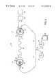
- FIG. 1 ais a schematic diagram of a photomixer transceiver that embodies the invention.
- FIG. 1 billustrates an enlarged schematic diagram of the photomixers and antennas of FIG. 1 a.
- FIG. 2illustrates experimental data for the photomixer transceiver of FIG. 1 .
- FIG. 3illustrates a schematic diagram of a spectrometer that uses the photomixer transceiver that embodies the invention.
- FIG. 4illustrates a schematic diagram of an imaging system that uses the photomixer transceiver that embodies the invention.
- FIG. 5illustrates a schematic diagram of a network analyzer that uses the photomixer transceiver that embodies the invention.
- FIG. 6illustrates a schematic diagram of a communications system that uses the photomixer transceiver that embodies the invention.
- FIG. 1 ais a schematic diagram of a photomixer transceiver 10 comprising a photomixer transmitter 12 and a photomixer receiver 14 that embodies the invention.
- the transceiver 10includes a first 16 and a second source 18 of coherent radiation that generates a first and a second beam of coherent light at a first and a second distinct frequency ⁇ 1 and ⁇ 2 , respectively.
- the first and second beammay be continuous wave (CW) or pulsed.
- the first source 16 and the second source 18include diode lasers that emit near-infrared radiation.
- Each diode lasermay be a distributed-Bragg-reflector (DBR) or distributed feedback (DFB) diode laser.
- DBRdistributed-Bragg-reflector
- DFBdistributed feedback
- the photomixer transceiver 10includes a beam splitter 20 that separates each of the first and the second beams of light into a first 22 and a second optical path 24 that terminate at the photomixer transmitter 12 and the photomixer receiver 14 , respectively.
- the first and the second beam of lightmay be guided through the first 22 and the second optical path 24 by an optical fiber or may be focused along the first 22 and the second optical path 24 by lenses (not shown).
- the photomixer transmitter 12includes a first photomixer 26 that, in one embodiment, includes a low-temperature-grown (LTG) GaAs photoconductive material.
- LTG GaAsis a particularly good photoconductive material for high speed photoconductive correlators because it exhibits very short electron-hole lifetimes ( ⁇ 1 ps), has high electrical breakdown field (>10 6 V/cm), and has high mobility relative to other photoconductors having comparable lifetimes.
- the first photomixer 26includes a photoconductor having an active region that has dimensions of approximately 20 ⁇ 20- ⁇ m.
- the first photomixer 26is optically coupled to the first optical path 22 .
- the first photomixer 26may be coupled to the first optical path 22 by numerous methods known in the art.
- an optical fiberdefines the first optical path and the first photomixer 26 is coupled to the optical fiber by butt coupling.
- the first optical pathis defined by at least one lens (not shown) and the first photomixer 26 is positioned in the first optical path 22 .
- the first photomixer 26is biased with a voltage source 32 that generates a DC or an AC voltage.
- the bias voltagecauses a current to flow through the first photomixer 26 at frequency ⁇ .
- the first photomixer 26may be biased by numerous methods known in the art.
- the first photomixer 26is embedded in a transmission line or waveguide geometry such as a co-planar waveguide and a bias voltage is applied with a bias T.
- the co-planar waveguidemay transition into a 50- ⁇ coaxial line (not shown) that connects the photomixer transmitter 12 to the photomixer receiver 14 .
- the first photomixer 12is connected directly to the voltage source 32 .
- the voltage source 32biases the first photomixer 26 to generate a current having a frequency approximately equal to the difference frequency ⁇ .
- a first antenna 28is electrically coupled to the first photomixer 26 .
- the first antenna 28is shown as a spiral antenna 28 .
- the first antenna 28may be an interdigitated electrode antenna.
- the interdigitated electrode antennais approximately 0.2- ⁇ m wide by approximately 0.4 to 0.6 ⁇ m.
- a dielectric lens 30such as a silicon lens, may be used to focus the transmitted radiation. Numerous other antenna structures, such as planar antennas and horn antennas, that are known in the art, may also be used.
- the first antenna 28radiates a signal corresponding to the current generated by the first photomixer 26 .
- the photomixer transmitter 12can be represented as a transmitter equivalent circuit comprising the series combination of the first photomixer conductance G(t) at the difference frequency ⁇ , the voltage source 32 , and the first antenna impedance.
- the signalpropagates through a medium 34 placed between the photomixer transmitter 12 and the photomixer receiver 14 .
- the photomixer receiver 14includes a second antenna 36 that is positioned to receive the signal radiated by the first antenna 28 .
- a dielectric lens 30may direct the signal radiated by the first antenna 28 to the second antenna 36 , which is shown as a spiral antenna.
- the second antenna 36generates a time varying voltage in response to the signal.
- the second antenna 36may also be an interdigitated electrode antenna, a planar antenna, or a horn antenna.
- a second photomixer 38is electrically coupled to the second antenna 36 and is optically coupled to the second optical path 24 by numerous methods known in the art as described in connection with the first photomixer 26 .
- the second photomixer 38comprises LTG GaAs.
- a conductance (not shown) of the second photomixer 38is modulated at the difference frequency ⁇ in response to the first 16 and the second light source 18 .
- the optical beating of the first and the second light beams by way of path 24periodically raises the photoconductance of the second photomixer 38 such that a current signal is generated in response to the time varying voltage generated by the second antenna 36 .
- an intermediate frequency (IF) amplifier 40is electrically coupled to the second photomixer 38 and amplifies intermediate frequencies generated by the second photomixer 38 .
- an output of the IF amplifiercan be used to measure Doppler shifted signals from a target that reflects a signal transmitted by the photomixer transmitter 12 .
- a transimpedance amplifier 42is electrically coupled to the second photomixer 38 .
- the transimpedance amplifier 42generates a DC voltage in response to the current signal generated by the second photomixer 38 .
- the DC voltage measured by the transimpedance amplifier 42is directly proportional to the radiation incident on the photomixer receiver 14 as described below.
- the photomixer receiver 14 coupled to the transimpedance amplifier 42can be represented as a receiver equivalent circuit comprising the series combination of the second photomixer conductance G(t) at the difference frequency ⁇ , the second antenna impedance, and the transimpedance amplifier 42 .
- the radiation received by the second antenna 36induces a time-varying voltage V(t) across the second antenna impedance.
- the current flowing through the receiver equivalent circuitis approximately V(t)G(t).
- the currentwill have a time-varying term at frequency 2 ⁇ and a DC term that is proportional to V(t).
- the DC term detected by the transimpedance amplifier 42is directly proportional to the radiation incident on the second antenna 36 .
- a processor 44may be in communication with the second photomixer 38 either directly or through the IF amplifier 40 and/or the transimpedance amplifier 42 .
- the processor 44processes the current signal generated by the second photomixer 38 , the IF frequency signal generated by the IF amplifier 40 , and/or the DC voltage signal generated by the transimpedance amplifier 42 .
- RF and quasi-optical transceiversthat require processing of the received signals. These applications include spectroscopy, imaging, network analysis, radar and communications.
- FIG. 1 billustrates an enlarged schematic diagram of the photomixers and antennas of FIG. 1 a .
- the first 28 and second antenna 36are shown as spiral antennas, they may also be interdigitated electrode antennas, planar antennas, or horn antennas.
- the photomixer transceiver 10 of FIG. 1has numerous advantages over the prior art.
- One advantageis that the photomixer transceiver 10 is highly frequency agile and can be continuously tuned. Some applications such as spectroscopy require the transceiver to operate at more than one difference frequency. If the first 16 and the second source 18 comprise diode lasers, the emission wavelength of one of the diode lasers can be temperature tuned.
- photomixer transceiver 10is relatively insensitive to frequency drift occurring in the first 16 and the second source 18 . Any drift in the frequency stability of the first 16 and the second source 18 will change the difference frequency ⁇ and modulate the conductance of both the first 26 and the second photomixer 38 at the same changed difference frequency ⁇ . Therefore, any frequency drift in the transmitted signal is exactly tracked by the frequency drifts in the photomixer receiver 14 .
- the present inventionalso features a method of transmitting and receiving RF and quasi-optical radiation.
- a first and a second light sourcethat generates a first and a second beam of light at a first frequency and a second frequency, respectively is provided.
- the first and second light sourcesmay be pulsed or a CW light source.
- a conductance of a first photomixeris modulated at a difference frequency that is approximately equal to the difference between the first and the second frequencies.
- the modulated conductancegenerates a signal having the difference frequency.
- the signalis transmitted through a medium.
- the signal transmitted through the mediumis received and a time varying voltage is generated in response to the signal.
- a conductance of a second photomixeris modulated at the difference frequency.
- a current signalis generated in response to the time varying signal received by the second antenna and the modulated conductance of the second photomixer.
- a DC voltagemay be detected in response to the current signal generated.
- the present inventionalso features a method of forming a Doppler radar image.
- the first antennaradiates a signal at the difference frequency.
- the signalis reflected off of a moving target object (not shown) where it is Doppler-shifted.
- the resulting Doppler-shifted signalemanates from the target object in the direction of the second antenna.
- the Doppler-shifted signalis received by the second antenna 36 .
- the second photomixer 38generates a current signal in response to the time varying voltage generated by the second antenna 36 .
- the IF amplifier 40amplifies the IF signals in the current signal.
- the processor 44processes the IF signals as radar data.
- the maximum Doppler-shift that can be measuredis determined by the bandwidth of the IF amplifier 40 and by the intrinsic linewidth of the first and the second light source (typically ⁇ 100 kHz for diode lasers).
- FIG. 2illustrates experimental data for the photomixer transceiver of FIG. 1 .
- the first light sourcewas a diode laser emitting radiation at approximately 850 nm.
- the second light sourcewas a tunable diode laser with a center frequency of approximately 852 nm.
- a silicon hyper-hemispherical lenswas used to focus the transmitted radiation onto a spiral antenna.
- the area of the receiver photomixer 38was approximately 64 square microns.
- the signal detected with the spiral antennais plotted as a function of difference frequency. Radiation was detected from approximately 0.1 to 1.0 Terahertz.
- FIG. 3illustrates a schematic diagram of a spectrometer 100 that uses the photomixer transceiver that embodies the invention.
- the transceiver of FIG. 1is adapted for use as a spectrometer.
- a medium 102 to be analyzedis positioned in the path of the signals generated by the photomixer transmitter 12 .
- the medium to be analyzedmay be any medium with at least some transmission in the RF and quasi-optical region.
- the mediummay be a solid, liquid, gas or even a plasma. Gases, however, have sharp and characteristic absorption lines in the quasi-optical region and, therefore are easy to analyze with a quasi-optical spectrometer.
- the signals generated by the photomixer transmitter 12 at the difference frequencypropagate through the medium 102 and are received by the photomixer receiver 14 .
- the difference frequencycan be changed by adjusting the frequency of at least one of the first 16 or second sources 18 with a frequency tuning device 104 such as a temperature controller.
- An analyzer 106samples and measures at least one of amplitude or phase of the current signal generated by the photomixer receiver 14 .
- the analyzer 106determines at least one of the absorption or dispersion characteristics of the medium from the amplitude or phase measurement.
- the analyzer 106may also identify the medium or certain properties of the medium.
- the present inventionalso features a method of performing real time spectroscopy by CW or pulse laser photoconductive sampling.
- the methodincludes providing a first and a second light source that generates a first and a second beam of light at a first and a second frequency, respectively.
- a conductance of a first photomixeris modulated at a difference frequency that is approximately equal to the difference between the first and the second frequencies.
- the modulated conductancegenerates a signal having the difference frequency.
- the signalis transmitted through a medium to be analyzed.
- the signal transmitted through the mediumis received and a time varying voltage is generated in response to the signal.
- a conductance of a second photomixeris modulated at the difference frequency.
- a current signalis generated in response to the time varying signal received by the second antenna and the modulated conductance of the second photomixer.
- At least one of amplitude or phase of the current signalis measured. At least one of the absorption or dispersion characteristics of the medium is determined from the amplitude or phase measurement. The absorption or dispersion characteristics of the medium may be determined by measuring a frequency chirp in the current signal. From the absorption or dispersion characteristics, the presence of a particular medium can be determined. The method may be repeated for different difference frequencies by first changing at least one of the first or the second frequency and then repeating the steps of the method.
- the method of performing real time spectroscopy according to this inventionhas numerous advantages over the prior art.
- One advantageis that the method has high spectral brightness and, therefore, high sensitivity because it uses high brightness diode lasers.
- this methodhas significantly higher spectral brightness ( ⁇ 10 6 times higher) than prior art time-domain sampling methods.
- Another advantageis that a spectrometer using this method would be relatively compact and inexpensive because it uses commercially available diode lasers. In addition, such a spectrometer would operate at room temperature and would not require the use of a cryogenically cooled detector.
- the spectrometer of the present inventionis useful for many applications including real-time trace gas monitoring. Such monitoring is important for the semiconductor fabrication and other manufacturing industries and for numerous military applications. Such monitoring is also important for pollution monitoring.
- the high spectral brightness and simplicity of the spectrometer of the present inventionare important advantages over prior art Fourier transform spectrometers or photoconductive-switch systems that use pulsed lasers.
- FIG. 4illustrates a schematic diagram of an imaging system using the photomixer transceiver that embodies the invention.
- the photomixer transceiver of FIG. 1is adapted for use as an imaging system.
- the signal generated by the photomixer transmitter 12is focused by a first dielectric lens 152 to an object 154 to be imaged.
- the signalcan be focused to the diffraction limit.
- the object 154 to be imagedis typically partially absorbing to quasi-optical radiation. Many materials have frequency dependent absorption and dispersion in the quasi-optical region. Polar liquids, such as water or solvents, are typically highly absorbing in this region. In contrast, most dry, nonmetallic objects such as plastics, paper, cardboard, glass, and many other dielectric materials are highly transparent in the quasi-optical frequency range.
- the signalpropagates through the object 154 to a second dielectric lens 156 .
- the second lens 156focuses the signal onto the second antenna 36 .
- the current signal generated by the second photomixercontains both amplitude and phase information about the object 154 that can be used to create an image of the object 154 .
- An image processor 158processes the amplitude and phase information and generates imaging data.
- the imaging system of the present inventionis useful for inspection. There are many applications in packaging, quality control, and security, where it is important to look through some materials to reveal certain objects. For example, an imaging system of the present invention can be used to scan envelopes for letter bombs or to scan passengers for weapons, explosives or drugs.
- the imaging system of the present inventionis useful for detecting small amounts of water or solvents.
- One exampleis in the food processing industry because moisture in many foods has to be maintained within certain limits.
- Another exampleis in the paper industry.
- the imaging system of the present inventionis also useful for determining the doping profile in semiconductor and superconductor materials.
- the carriers that conduct currents in semiconductors and superconductorsare highly absorbing to quasi-optical frequencies.
- An imaging system according to the present inventionhas a high sensitivity to charge carriers in semiconductor materials.
- the imaging system of the present inventionis also useful for measuring the frequency dependent absorption and the frequency dependent refractive index of a material.
- the absorption coefficient and the dielectric constant of many materialsusually varies significantly.
- Signals transmitted through the materialwill be attenuated according to the material's frequency dependent absorption.
- the signalsmay also be frequency chirped according to the material's frequency dependent refractive index. For example, if the refractive index rises with frequency, low frequencies will travel faster through the material than high frequencies. Therefore, the low frequencies end up at the leading edge of the pulse, while the high frequencies trail behind the leading edge of the pulse.
- the present inventionalso features a method of imaging an object.
- the methodincludes providing a first and a second light source that generates a first and a second beam of light at a first and a second frequency, respectively.
- a conductance of a first photomixeris modulated at a difference frequency that is approximately equal to the difference between the first and the second frequencies in response to the first and the second light beam to generate a signal having the difference frequency.
- the signalis transmitted through an object to be imaged and then received.
- the signalmay be transmitted through a predetermined position on the object.
- a time varying voltageis generated in response to the signal.
- a conductance of a second photomixeris modulated at the difference frequency in response to the first and the second light beam.
- a current signalis generated in response to the signal received and the modulated conductance of the second photomixer.
- the current signalmay be converted to digital data or it may be frequency converted to a lower frequency. At least one of the amplitude or the phase of the current signal is measured and processed to form an image of the object.
- One advantage of the imaging system of the present inventionis that it provides high spectral brightness. Numerous applications, such as imaging the strength of a narrow band signal from a molecular absorption process, require high spectral brightness.
- FIG. 5illustrates a schematic diagram of a network analyzer 180 that uses the photomixer transceiver that embodies the invention.
- the transceiver of FIG. 1is adapted for use as a network analyzer.
- the photomixer transmitter 12 and the photomixer receiver 14are both mounted in co-planar waveguides 182 .
- the co-planar waveguides 182may transition into a 50- ⁇ coaxial transmission line 184 that connects the photomixer transmitter 12 and the photomixer receiver 14 to a device 186 under test.
- Numerous other waveguide structures known in the artcan be used to mount the photomixer transmitter 12 and the photomixer receiver 14 and to connect them to the device 186 under test.
- An isolator 188may be used to eliminate reflections and standing waves in the coaxial transmission line 184 .
- a second photomixer receiver(not shown) is coupled to a reflection port of the device 186 under test and receives signals reflected from the device 186 under test.
- Using the first 14 and the second photomixer receiversallows both transmission and reflection measurements of the device 186 under test without reconfiguring the device.
- an additional photomixer transmitter (not shown) and an additional photomixer receiver (not shown)are included to fully characterize a two port device under test without reconfiguring the device.
- the transfer characteristic of a narrow bandpass filterhas been measured with the network analyzer of FIG. 5 and the results agreed with the transfer characteristic measured using a commercial microwave spectrum analyzer.
- the present inventionalso features a method of network analysis.
- the methodincludes providing a first and a second light source that generates a first and a second beam of light at a first and a second frequency, respectively.
- a conductance of a first photomixeris modulated at a difference frequency that is approximately equal to the difference between the first and the second frequencies in response to the first and the second light beam to generate a signal having the difference frequency.
- the signalis transmitted through or reflected from a network to be analyzed and then received.
- a time varying voltageis generated in response to the signal.
- a conductance of a second photomixeris modulated at the difference frequency in response to the first and the second light beam.
- a current signalis generated in response to the signal received and the modulated conductance of the second photomixer. At least one of the amplitude or the phase of the current signal is measured and processed to determine at least one of a transmission or a reflection parameter of the network such as the scattering parameter.
- FIG. 6illustrates a schematic diagram of a communications system 200 that uses the photomixer transceiver that embodies the invention.
- the transceiver of FIG. 1is adapted to communicate data.
- a modulator 201is coupled to at least one of the first 16 or the second source 18 .
- the modulator 201is used to modulate onto the first and/or the second beam a data stream to be communicated.
- a down converter 202may be used to downconvert the modulated signal received by the photomixer receiver 14 .
- a demodulator 204is used to demodulate the data from the received signal.
- a method of quasi-optical communicationsincludes providing a first and a second light source that generates a first and a second beam of light at a first and a second frequency, respectively.
- the first and the second beam of lightare modulated with data.
- a conductance of a first photomixeris modulated at a difference frequency that is approximately equal to the difference between the first and the second frequencies in response to the first and the second beam of light to generate a modulated signal having the difference frequency.
- the modulated signalis transmitted through a medium which may be a transmission line or which may be free space.
- the modulated signalis received and a time varying voltage is generated in response to the modulated signal.
- a conductance of a second photomixeris modulated at the difference frequency in response to the first and the second light beam.
- a current signalis generated in response to the modulated signal received and the modulated conductance of the second photomixer. The current signal is then downconverted and demodulated.
Landscapes
- Investigating Or Analysing Materials By Optical Means (AREA)
Abstract
Description
Claims (33)
Priority Applications (1)
| Application Number | Priority Date | Filing Date | Title |
|---|---|---|---|
| US09/072,362US6348683B1 (en) | 1998-05-04 | 1998-05-04 | Quasi-optical transceiver having an antenna with time varying voltage |
Applications Claiming Priority (1)
| Application Number | Priority Date | Filing Date | Title |
|---|---|---|---|
| US09/072,362US6348683B1 (en) | 1998-05-04 | 1998-05-04 | Quasi-optical transceiver having an antenna with time varying voltage |
Publications (1)
| Publication Number | Publication Date |
|---|---|
| US6348683B1true US6348683B1 (en) | 2002-02-19 |
Family
ID=22107095
Family Applications (1)
| Application Number | Title | Priority Date | Filing Date |
|---|---|---|---|
| US09/072,362Expired - LifetimeUS6348683B1 (en) | 1998-05-04 | 1998-05-04 | Quasi-optical transceiver having an antenna with time varying voltage |
Country Status (1)
| Country | Link |
|---|---|
| US (1) | US6348683B1 (en) |
Cited By (203)
| Publication number | Priority date | Publication date | Assignee | Title |
|---|---|---|---|---|
| US20040130725A1 (en)* | 2001-07-02 | 2004-07-08 | Takashi Kido | Propagation measuring apparatus and a propagation measuring method |
| WO2005108940A1 (en)* | 2004-05-04 | 2005-11-17 | Loeffler Torsten | Device and method for detecting high-frequency radiation |
| US20050259908A1 (en)* | 2002-06-21 | 2005-11-24 | Silvano Donati | Millimeter wave transmitter using optical heterodyning |
| US20060033392A1 (en)* | 2004-08-12 | 2006-02-16 | Ritchey Jonathan G | Polyphasic multi-coil generator |
| US20060210214A1 (en)* | 2005-03-15 | 2006-09-21 | Uhlhorn Brian L | Integrated volume holographic optical circuit apparatus |
| US20060226348A1 (en)* | 2005-03-31 | 2006-10-12 | Goodrich Corporation | System and method for power ratio determination with common mode suppression through electric field differencing |
| WO2006123163A1 (en)* | 2005-05-18 | 2006-11-23 | The Centre For Integrated Photonics Limited | Method to generate and detect terahertz radiation |
| US20070194253A1 (en)* | 2004-09-30 | 2007-08-23 | Seizi Nishizawa | Infrared light emitting device, infrared light detecting device, time-domain pulsed spectrometer apparatus, and infrared light emitting method |
| US7291839B1 (en)* | 2004-05-03 | 2007-11-06 | Emcore Corporation | Subcentimeter radiation detection and frequency domain spectroscopy |
| GB2438215A (en)* | 2006-05-19 | 2007-11-21 | Teraview Ltd | Terahertz investigation apparatus and method |
| US20080179527A1 (en)* | 2007-01-31 | 2008-07-31 | Demers Joseph R | Pulsed terahertz spectrometer |
| US20080179528A1 (en)* | 2007-01-31 | 2008-07-31 | Emcore Corp. | Pulsed terahertz frequency domain spectrometer with single mode-locked laser and dispersive phase modulator |
| US20090269082A1 (en)* | 2008-04-29 | 2009-10-29 | Textron Systems Corporation | Heterodyne receiver using differential temperature control of laser sources |
| US7616851B1 (en)* | 2008-06-26 | 2009-11-10 | Lockheed Martin Corporation | Tunable wavelength filter device |
| US20090283680A1 (en)* | 2008-05-19 | 2009-11-19 | Emcore Corporation | Terahertz Frequency Domain Spectrometer with Controllable Phase Shift |
| US20100001189A1 (en)* | 2008-04-18 | 2010-01-07 | New Jersey Institute Of Technology | Methods of rapid phase modulation of thz radiation for high speed thz imaging, spectroscopy, and communications devices and systems |
| EP2166325A2 (en) | 2008-09-19 | 2010-03-24 | Goodrich Corporation | System and method for signal extraction by path modulation |
| EP2166324A2 (en) | 2008-09-19 | 2010-03-24 | Goodrich Corporation | System and method for suppressing noise by frequency dither |
| US20100277726A1 (en)* | 2008-04-04 | 2010-11-04 | Emcore Corporation | Terahertz Frequency Domain Spectrometer with Integrated Dual Laser Module |
| US20100314545A1 (en)* | 2008-05-19 | 2010-12-16 | Emcore Corporation | Terahertz Frequency Domain Spectrometer with Frequency Shifting of Source Laser Beam |
| US8003947B1 (en) | 2010-02-25 | 2011-08-23 | Goodrich Corporation | System and method for magnitude and phase retrieval by path modulation |
| US20110208480A1 (en)* | 2010-02-25 | 2011-08-25 | Goodrich Corporation | Apparatus, method and computer-readable storage medium for processing a signal in a spectrometer system |
| US20110235022A1 (en)* | 2010-03-25 | 2011-09-29 | Goodrich Corporation | Apparatus, method and computer-readable storage medium for determining the ring-down time in a spectrometer system |
| US20110233406A1 (en)* | 2010-03-25 | 2011-09-29 | Goodrich Corporation | Multi-channel optical cell |
| DE102010019134A1 (en) | 2010-04-30 | 2011-11-03 | Fraunhofer-Gesellschaft zur Förderung der angewandten Forschung e.V. | Arrangement for generating a signal with adjustable time or phase position |
| US8106563B2 (en) | 2006-06-08 | 2012-01-31 | Exro Technologies Inc. | Polyphasic multi-coil electric device |
| DE102010040356A1 (en) | 2010-09-07 | 2012-03-08 | Universität Zu Köln | THz spectrometer and THz spectroscopy method |
| US20120082199A1 (en)* | 2010-10-05 | 2012-04-05 | Sony Corporation | Antenna measurement system and method |
| US8212445B2 (en) | 2004-08-12 | 2012-07-03 | Exro Technologies Inc. | Polyphasic multi-coil electric device |
| CN102842839A (en)* | 2011-06-24 | 2012-12-26 | 精工爱普生株式会社 | Terahertz wave generating device, camera, imaging device, and measurement device |
| DE102011079948A1 (en)* | 2011-07-27 | 2013-01-31 | Universität Zu Köln | Measuring device for determining difference frequency in THz range, has evaluation arrangement which derives measure of frequency difference by resulting electrical signal, while signal with function of difference frequency is measured |
| US20130292586A1 (en)* | 2010-10-29 | 2013-11-07 | Agency For Science, Technology And Research | THz PHOTOMIXER EMITTER AND METHOD |
| US8805148B2 (en) | 2011-07-14 | 2014-08-12 | International Business Machines Corporation | Generation of terahertz electromagnetic waves in graphene by coherent photon-mixing |
| US9029775B2 (en) | 2008-05-19 | 2015-05-12 | Joseph R. Demers | Terahertz frequency domain spectrometer with phase modulation of source laser beam |
| US9086374B1 (en) | 2014-04-25 | 2015-07-21 | Joseph R. Demers | Terahertz spectrometer with phase modulation and method |
| US9103715B1 (en) | 2013-03-15 | 2015-08-11 | Joseph R. Demers | Terahertz spectrometer phase modulator control using second harmonic nulling |
| US9239264B1 (en) | 2014-09-18 | 2016-01-19 | Joseph R. Demers | Transceiver method and apparatus having phase modulation and common mode phase drift rejection |
| US9279723B2 (en) | 2010-08-19 | 2016-03-08 | Novatrans Group Sa | Terahertz spectroscopy system and method |
| US9335414B2 (en)* | 2014-07-11 | 2016-05-10 | Raytheon Company | Frequency agile LADAR |
| US20160149312A1 (en)* | 2014-11-20 | 2016-05-26 | At&T Intellectual Property I, Lp | Apparatus for converting wireless signals and electromagnetic waves and methods thereof |
| US9400214B1 (en) | 2013-03-15 | 2016-07-26 | Joseph R. Demers | Terahertz frequency domain spectrometer with a single photoconductive element for terahertz signal generation and detection |
| US9404853B1 (en) | 2014-04-25 | 2016-08-02 | Joseph R. Demers | Terahertz spectrometer with phase modulation |
| US9429473B2 (en) | 2014-10-16 | 2016-08-30 | Joseph R. Demers | Terahertz spectrometer and method for reducing photomixing interference pattern |
| US9431564B2 (en)* | 2008-07-29 | 2016-08-30 | Thales Holding Uk Plc | Photoconductive switch |
| DE102015214289B3 (en)* | 2015-07-28 | 2016-09-29 | Fraunhofer-Gesellschaft zur Förderung der angewandten Forschung e.V. | Vector network analyzer |
| US9544006B2 (en) | 2014-11-20 | 2017-01-10 | At&T Intellectual Property I, L.P. | Transmission device with mode division multiplexing and methods for use therewith |
| US9577307B2 (en) | 2014-10-21 | 2017-02-21 | At&T Intellectual Property I, L.P. | Guided-wave transmission device and methods for use therewith |
| US9596001B2 (en) | 2014-10-21 | 2017-03-14 | At&T Intellectual Property I, L.P. | Apparatus for providing communication services and methods thereof |
| US9608692B2 (en) | 2015-06-11 | 2017-03-28 | At&T Intellectual Property I, L.P. | Repeater and methods for use therewith |
| US9608740B2 (en) | 2015-07-15 | 2017-03-28 | At&T Intellectual Property I, L.P. | Method and apparatus for launching a wave mode that mitigates interference |
| US9615269B2 (en) | 2014-10-02 | 2017-04-04 | At&T Intellectual Property I, L.P. | Method and apparatus that provides fault tolerance in a communication network |
| US9628116B2 (en) | 2015-07-14 | 2017-04-18 | At&T Intellectual Property I, L.P. | Apparatus and methods for transmitting wireless signals |
| US9627768B2 (en) | 2014-10-21 | 2017-04-18 | At&T Intellectual Property I, L.P. | Guided-wave transmission device with non-fundamental mode propagation and methods for use therewith |
| US9640850B2 (en) | 2015-06-25 | 2017-05-02 | At&T Intellectual Property I, L.P. | Methods and apparatus for inducing a non-fundamental wave mode on a transmission medium |
| US9653770B2 (en) | 2014-10-21 | 2017-05-16 | At&T Intellectual Property I, L.P. | Guided wave coupler, coupling module and methods for use therewith |
| US9654173B2 (en) | 2014-11-20 | 2017-05-16 | At&T Intellectual Property I, L.P. | Apparatus for powering a communication device and methods thereof |
| US9661505B2 (en) | 2013-11-06 | 2017-05-23 | At&T Intellectual Property I, L.P. | Surface-wave communications and methods thereof |
| US9667317B2 (en) | 2015-06-15 | 2017-05-30 | At&T Intellectual Property I, L.P. | Method and apparatus for providing security using network traffic adjustments |
| US9685992B2 (en) | 2014-10-03 | 2017-06-20 | At&T Intellectual Property I, L.P. | Circuit panel network and methods thereof |
| US9692101B2 (en) | 2014-08-26 | 2017-06-27 | At&T Intellectual Property I, L.P. | Guided wave couplers for coupling electromagnetic waves between a waveguide surface and a surface of a wire |
| US9699785B2 (en) | 2012-12-05 | 2017-07-04 | At&T Intellectual Property I, L.P. | Backhaul link for distributed antenna system |
| US9705610B2 (en) | 2014-10-21 | 2017-07-11 | At&T Intellectual Property I, L.P. | Transmission device with impairment compensation and methods for use therewith |
| US9705561B2 (en) | 2015-04-24 | 2017-07-11 | At&T Intellectual Property I, L.P. | Directional coupling device and methods for use therewith |
| US9712350B2 (en) | 2014-11-20 | 2017-07-18 | At&T Intellectual Property I, L.P. | Transmission device with channel equalization and control and methods for use therewith |
| US9722318B2 (en) | 2015-07-14 | 2017-08-01 | At&T Intellectual Property I, L.P. | Method and apparatus for coupling an antenna to a device |
| US9729197B2 (en) | 2015-10-01 | 2017-08-08 | At&T Intellectual Property I, L.P. | Method and apparatus for communicating network management traffic over a network |
| US9735833B2 (en) | 2015-07-31 | 2017-08-15 | At&T Intellectual Property I, L.P. | Method and apparatus for communications management in a neighborhood network |
| US9742462B2 (en) | 2014-12-04 | 2017-08-22 | At&T Intellectual Property I, L.P. | Transmission medium and communication interfaces and methods for use therewith |
| US9749053B2 (en) | 2015-07-23 | 2017-08-29 | At&T Intellectual Property I, L.P. | Node device, repeater and methods for use therewith |
| US9749013B2 (en) | 2015-03-17 | 2017-08-29 | At&T Intellectual Property I, L.P. | Method and apparatus for reducing attenuation of electromagnetic waves guided by a transmission medium |
| US9748626B2 (en) | 2015-05-14 | 2017-08-29 | At&T Intellectual Property I, L.P. | Plurality of cables having different cross-sectional shapes which are bundled together to form a transmission medium |
| US9762289B2 (en) | 2014-10-14 | 2017-09-12 | At&T Intellectual Property I, L.P. | Method and apparatus for transmitting or receiving signals in a transportation system |
| US9769020B2 (en) | 2014-10-21 | 2017-09-19 | At&T Intellectual Property I, L.P. | Method and apparatus for responding to events affecting communications in a communication network |
| US9769128B2 (en) | 2015-09-28 | 2017-09-19 | At&T Intellectual Property I, L.P. | Method and apparatus for encryption of communications over a network |
| US9768833B2 (en) | 2014-09-15 | 2017-09-19 | At&T Intellectual Property I, L.P. | Method and apparatus for sensing a condition in a transmission medium of electromagnetic waves |
| US9780834B2 (en) | 2014-10-21 | 2017-10-03 | At&T Intellectual Property I, L.P. | Method and apparatus for transmitting electromagnetic waves |
| US9787412B2 (en) | 2015-06-25 | 2017-10-10 | At&T Intellectual Property I, L.P. | Methods and apparatus for inducing a fundamental wave mode on a transmission medium |
| US9793954B2 (en) | 2015-04-28 | 2017-10-17 | At&T Intellectual Property I, L.P. | Magnetic coupling device and methods for use therewith |
| US9794003B2 (en) | 2013-12-10 | 2017-10-17 | At&T Intellectual Property I, L.P. | Quasi-optical coupler |
| US9793955B2 (en) | 2015-04-24 | 2017-10-17 | At&T Intellectual Property I, Lp | Passive electrical coupling device and methods for use therewith |
| US9793951B2 (en) | 2015-07-15 | 2017-10-17 | At&T Intellectual Property I, L.P. | Method and apparatus for launching a wave mode that mitigates interference |
| US9800327B2 (en) | 2014-11-20 | 2017-10-24 | At&T Intellectual Property I, L.P. | Apparatus for controlling operations of a communication device and methods thereof |
| US9820146B2 (en) | 2015-06-12 | 2017-11-14 | At&T Intellectual Property I, L.P. | Method and apparatus for authentication and identity management of communicating devices |
| US9836957B2 (en) | 2015-07-14 | 2017-12-05 | At&T Intellectual Property I, L.P. | Method and apparatus for communicating with premises equipment |
| US9838896B1 (en) | 2016-12-09 | 2017-12-05 | At&T Intellectual Property I, L.P. | Method and apparatus for assessing network coverage |
| US9838078B2 (en) | 2015-07-31 | 2017-12-05 | At&T Intellectual Property I, L.P. | Method and apparatus for exchanging communication signals |
| US9847566B2 (en) | 2015-07-14 | 2017-12-19 | At&T Intellectual Property I, L.P. | Method and apparatus for adjusting a field of a signal to mitigate interference |
| US9847850B2 (en) | 2014-10-14 | 2017-12-19 | At&T Intellectual Property I, L.P. | Method and apparatus for adjusting a mode of communication in a communication network |
| US9853342B2 (en) | 2015-07-14 | 2017-12-26 | At&T Intellectual Property I, L.P. | Dielectric transmission medium connector and methods for use therewith |
| US9860075B1 (en) | 2016-08-26 | 2018-01-02 | At&T Intellectual Property I, L.P. | Method and communication node for broadband distribution |
| US9866276B2 (en) | 2014-10-10 | 2018-01-09 | At&T Intellectual Property I, L.P. | Method and apparatus for arranging communication sessions in a communication system |
| US9866309B2 (en) | 2015-06-03 | 2018-01-09 | At&T Intellectual Property I, Lp | Host node device and methods for use therewith |
| US9865911B2 (en) | 2015-06-25 | 2018-01-09 | At&T Intellectual Property I, L.P. | Waveguide system for slot radiating first electromagnetic waves that are combined into a non-fundamental wave mode second electromagnetic wave on a transmission medium |
| US9871283B2 (en) | 2015-07-23 | 2018-01-16 | At&T Intellectual Property I, Lp | Transmission medium having a dielectric core comprised of plural members connected by a ball and socket configuration |
| US9871282B2 (en) | 2015-05-14 | 2018-01-16 | At&T Intellectual Property I, L.P. | At least one transmission medium having a dielectric surface that is covered at least in part by a second dielectric |
| US9876571B2 (en) | 2015-02-20 | 2018-01-23 | At&T Intellectual Property I, Lp | Guided-wave transmission device with non-fundamental mode propagation and methods for use therewith |
| US9876605B1 (en) | 2016-10-21 | 2018-01-23 | At&T Intellectual Property I, L.P. | Launcher and coupling system to support desired guided wave mode |
| US9876264B2 (en) | 2015-10-02 | 2018-01-23 | At&T Intellectual Property I, Lp | Communication system, guided wave switch and methods for use therewith |
| US9882277B2 (en) | 2015-10-02 | 2018-01-30 | At&T Intellectual Property I, Lp | Communication device and antenna assembly with actuated gimbal mount |
| US9882257B2 (en) | 2015-07-14 | 2018-01-30 | At&T Intellectual Property I, L.P. | Method and apparatus for launching a wave mode that mitigates interference |
| US9887447B2 (en) | 2015-05-14 | 2018-02-06 | At&T Intellectual Property I, L.P. | Transmission medium having multiple cores and methods for use therewith |
| US9893795B1 (en) | 2016-12-07 | 2018-02-13 | At&T Intellectual Property I, Lp | Method and repeater for broadband distribution |
| US9906269B2 (en) | 2014-09-17 | 2018-02-27 | At&T Intellectual Property I, L.P. | Monitoring and mitigating conditions in a communication network |
| US9904535B2 (en) | 2015-09-14 | 2018-02-27 | At&T Intellectual Property I, L.P. | Method and apparatus for distributing software |
| US9911020B1 (en) | 2016-12-08 | 2018-03-06 | At&T Intellectual Property I, L.P. | Method and apparatus for tracking via a radio frequency identification device |
| US9913139B2 (en) | 2015-06-09 | 2018-03-06 | At&T Intellectual Property I, L.P. | Signal fingerprinting for authentication of communicating devices |
| US9912419B1 (en) | 2016-08-24 | 2018-03-06 | At&T Intellectual Property I, L.P. | Method and apparatus for managing a fault in a distributed antenna system |
| US9912382B2 (en) | 2015-06-03 | 2018-03-06 | At&T Intellectual Property I, Lp | Network termination and methods for use therewith |
| US9912027B2 (en) | 2015-07-23 | 2018-03-06 | At&T Intellectual Property I, L.P. | Method and apparatus for exchanging communication signals |
| US9917341B2 (en) | 2015-05-27 | 2018-03-13 | At&T Intellectual Property I, L.P. | Apparatus and method for launching electromagnetic waves and for modifying radial dimensions of the propagating electromagnetic waves |
| US9930668B2 (en) | 2013-05-31 | 2018-03-27 | At&T Intellectual Property I, L.P. | Remote distributed antenna system |
| US9927517B1 (en) | 2016-12-06 | 2018-03-27 | At&T Intellectual Property I, L.P. | Apparatus and methods for sensing rainfall |
| US9948333B2 (en) | 2015-07-23 | 2018-04-17 | At&T Intellectual Property I, L.P. | Method and apparatus for wireless communications to mitigate interference |
| US9948354B2 (en) | 2015-04-28 | 2018-04-17 | At&T Intellectual Property I, L.P. | Magnetic coupling device with reflective plate and methods for use therewith |
| US9967173B2 (en) | 2015-07-31 | 2018-05-08 | At&T Intellectual Property I, L.P. | Method and apparatus for authentication and identity management of communicating devices |
| US9973940B1 (en) | 2017-02-27 | 2018-05-15 | At&T Intellectual Property I, L.P. | Apparatus and methods for dynamic impedance matching of a guided wave launcher |
| US9991580B2 (en) | 2016-10-21 | 2018-06-05 | At&T Intellectual Property I, L.P. | Launcher and coupling system for guided wave mode cancellation |
| US9999038B2 (en) | 2013-05-31 | 2018-06-12 | At&T Intellectual Property I, L.P. | Remote distributed antenna system |
| US9997819B2 (en) | 2015-06-09 | 2018-06-12 | At&T Intellectual Property I, L.P. | Transmission medium and method for facilitating propagation of electromagnetic waves via a core |
| US9998870B1 (en) | 2016-12-08 | 2018-06-12 | At&T Intellectual Property I, L.P. | Method and apparatus for proximity sensing |
| US10009901B2 (en) | 2015-09-16 | 2018-06-26 | At&T Intellectual Property I, L.P. | Method, apparatus, and computer-readable storage medium for managing utilization of wireless resources between base stations |
| US10009065B2 (en) | 2012-12-05 | 2018-06-26 | At&T Intellectual Property I, L.P. | Backhaul link for distributed antenna system |
| US10009067B2 (en) | 2014-12-04 | 2018-06-26 | At&T Intellectual Property I, L.P. | Method and apparatus for configuring a communication interface |
| US10009063B2 (en) | 2015-09-16 | 2018-06-26 | At&T Intellectual Property I, L.P. | Method and apparatus for use with a radio distributed antenna system having an out-of-band reference signal |
| US10020844B2 (en) | 2016-12-06 | 2018-07-10 | T&T Intellectual Property I, L.P. | Method and apparatus for broadcast communication via guided waves |
| US10020587B2 (en) | 2015-07-31 | 2018-07-10 | At&T Intellectual Property I, L.P. | Radial antenna and methods for use therewith |
| US10027397B2 (en) | 2016-12-07 | 2018-07-17 | At&T Intellectual Property I, L.P. | Distributed antenna system and methods for use therewith |
| US10033107B2 (en) | 2015-07-14 | 2018-07-24 | At&T Intellectual Property I, L.P. | Method and apparatus for coupling an antenna to a device |
| US10033108B2 (en) | 2015-07-14 | 2018-07-24 | At&T Intellectual Property I, L.P. | Apparatus and methods for generating an electromagnetic wave having a wave mode that mitigates interference |
| US10044409B2 (en) | 2015-07-14 | 2018-08-07 | At&T Intellectual Property I, L.P. | Transmission medium and methods for use therewith |
| US10069535B2 (en) | 2016-12-08 | 2018-09-04 | At&T Intellectual Property I, L.P. | Apparatus and methods for launching electromagnetic waves having a certain electric field structure |
| US10079661B2 (en) | 2015-09-16 | 2018-09-18 | At&T Intellectual Property I, L.P. | Method and apparatus for use with a radio distributed antenna system having a clock reference |
| US10090594B2 (en) | 2016-11-23 | 2018-10-02 | At&T Intellectual Property I, L.P. | Antenna system having structural configurations for assembly |
| US10090606B2 (en) | 2015-07-15 | 2018-10-02 | At&T Intellectual Property I, L.P. | Antenna system with dielectric array and methods for use therewith |
| US10103422B2 (en) | 2016-12-08 | 2018-10-16 | At&T Intellectual Property I, L.P. | Method and apparatus for mounting network devices |
| US10103801B2 (en) | 2015-06-03 | 2018-10-16 | At&T Intellectual Property I, L.P. | Host node device and methods for use therewith |
| US10135145B2 (en) | 2016-12-06 | 2018-11-20 | At&T Intellectual Property I, L.P. | Apparatus and methods for generating an electromagnetic wave along a transmission medium |
| US10136434B2 (en) | 2015-09-16 | 2018-11-20 | At&T Intellectual Property I, L.P. | Method and apparatus for use with a radio distributed antenna system having an ultra-wideband control channel |
| US10135146B2 (en) | 2016-10-18 | 2018-11-20 | At&T Intellectual Property I, L.P. | Apparatus and methods for launching guided waves via circuits |
| US10135147B2 (en) | 2016-10-18 | 2018-11-20 | At&T Intellectual Property I, L.P. | Apparatus and methods for launching guided waves via an antenna |
| US10142086B2 (en) | 2015-06-11 | 2018-11-27 | At&T Intellectual Property I, L.P. | Repeater and methods for use therewith |
| US10139820B2 (en) | 2016-12-07 | 2018-11-27 | At&T Intellectual Property I, L.P. | Method and apparatus for deploying equipment of a communication system |
| US10144036B2 (en) | 2015-01-30 | 2018-12-04 | At&T Intellectual Property I, L.P. | Method and apparatus for mitigating interference affecting a propagation of electromagnetic waves guided by a transmission medium |
| US10148016B2 (en) | 2015-07-14 | 2018-12-04 | At&T Intellectual Property I, L.P. | Apparatus and methods for communicating utilizing an antenna array |
| US10168695B2 (en) | 2016-12-07 | 2019-01-01 | At&T Intellectual Property I, L.P. | Method and apparatus for controlling an unmanned aircraft |
| US10170840B2 (en) | 2015-07-14 | 2019-01-01 | At&T Intellectual Property I, L.P. | Apparatus and methods for sending or receiving electromagnetic signals |
| US10178445B2 (en) | 2016-11-23 | 2019-01-08 | At&T Intellectual Property I, L.P. | Methods, devices, and systems for load balancing between a plurality of waveguides |
| US10205655B2 (en) | 2015-07-14 | 2019-02-12 | At&T Intellectual Property I, L.P. | Apparatus and methods for communicating utilizing an antenna array and multiple communication paths |
| US10224634B2 (en) | 2016-11-03 | 2019-03-05 | At&T Intellectual Property I, L.P. | Methods and apparatus for adjusting an operational characteristic of an antenna |
| US10225025B2 (en) | 2016-11-03 | 2019-03-05 | At&T Intellectual Property I, L.P. | Method and apparatus for detecting a fault in a communication system |
| US10243784B2 (en) | 2014-11-20 | 2019-03-26 | At&T Intellectual Property I, L.P. | System for generating topology information and methods thereof |
| US10243270B2 (en) | 2016-12-07 | 2019-03-26 | At&T Intellectual Property I, L.P. | Beam adaptive multi-feed dielectric antenna system and methods for use therewith |
| US10264586B2 (en) | 2016-12-09 | 2019-04-16 | At&T Mobility Ii Llc | Cloud-based packet controller and methods for use therewith |
| US10291334B2 (en) | 2016-11-03 | 2019-05-14 | At&T Intellectual Property I, L.P. | System for detecting a fault in a communication system |
| US10291311B2 (en) | 2016-09-09 | 2019-05-14 | At&T Intellectual Property I, L.P. | Method and apparatus for mitigating a fault in a distributed antenna system |
| US10298293B2 (en) | 2017-03-13 | 2019-05-21 | At&T Intellectual Property I, L.P. | Apparatus of communication utilizing wireless network devices |
| US10305190B2 (en) | 2016-12-01 | 2019-05-28 | At&T Intellectual Property I, L.P. | Reflecting dielectric antenna system and methods for use therewith |
| US10312567B2 (en) | 2016-10-26 | 2019-06-04 | At&T Intellectual Property I, L.P. | Launcher with planar strip antenna and methods for use therewith |
| US10320586B2 (en) | 2015-07-14 | 2019-06-11 | At&T Intellectual Property I, L.P. | Apparatus and methods for generating non-interfering electromagnetic waves on an insulated transmission medium |
| US10326494B2 (en) | 2016-12-06 | 2019-06-18 | At&T Intellectual Property I, L.P. | Apparatus for measurement de-embedding and methods for use therewith |
| US10326689B2 (en) | 2016-12-08 | 2019-06-18 | At&T Intellectual Property I, L.P. | Method and system for providing alternative communication paths |
| US10340601B2 (en) | 2016-11-23 | 2019-07-02 | At&T Intellectual Property I, L.P. | Multi-antenna system and methods for use therewith |
| US10340983B2 (en) | 2016-12-09 | 2019-07-02 | At&T Intellectual Property I, L.P. | Method and apparatus for surveying remote sites via guided wave communications |
| US10340573B2 (en) | 2016-10-26 | 2019-07-02 | At&T Intellectual Property I, L.P. | Launcher with cylindrical coupling device and methods for use therewith |
| US10340600B2 (en) | 2016-10-18 | 2019-07-02 | At&T Intellectual Property I, L.P. | Apparatus and methods for launching guided waves via plural waveguide systems |
| US10340603B2 (en) | 2016-11-23 | 2019-07-02 | At&T Intellectual Property I, L.P. | Antenna system having shielded structural configurations for assembly |
| US10341142B2 (en) | 2015-07-14 | 2019-07-02 | At&T Intellectual Property I, L.P. | Apparatus and methods for generating non-interfering electromagnetic waves on an uninsulated conductor |
| US10355367B2 (en) | 2015-10-16 | 2019-07-16 | At&T Intellectual Property I, L.P. | Antenna structure for exchanging wireless signals |
| US10361489B2 (en) | 2016-12-01 | 2019-07-23 | At&T Intellectual Property I, L.P. | Dielectric dish antenna system and methods for use therewith |
| US10359749B2 (en) | 2016-12-07 | 2019-07-23 | At&T Intellectual Property I, L.P. | Method and apparatus for utilities management via guided wave communication |
| US10374316B2 (en) | 2016-10-21 | 2019-08-06 | At&T Intellectual Property I, L.P. | System and dielectric antenna with non-uniform dielectric |
| US10382976B2 (en) | 2016-12-06 | 2019-08-13 | At&T Intellectual Property I, L.P. | Method and apparatus for managing wireless communications based on communication paths and network device positions |
| US10389029B2 (en) | 2016-12-07 | 2019-08-20 | At&T Intellectual Property I, L.P. | Multi-feed dielectric antenna system with core selection and methods for use therewith |
| US10389037B2 (en) | 2016-12-08 | 2019-08-20 | At&T Intellectual Property I, L.P. | Apparatus and methods for selecting sections of an antenna array and use therewith |
| US10411356B2 (en) | 2016-12-08 | 2019-09-10 | At&T Intellectual Property I, L.P. | Apparatus and methods for selectively targeting communication devices with an antenna array |
| US10439675B2 (en) | 2016-12-06 | 2019-10-08 | At&T Intellectual Property I, L.P. | Method and apparatus for repeating guided wave communication signals |
| US10446936B2 (en) | 2016-12-07 | 2019-10-15 | At&T Intellectual Property I, L.P. | Multi-feed dielectric antenna system and methods for use therewith |
| US10498446B2 (en) | 2017-04-20 | 2019-12-03 | Harris Corporation | Electronic system including waveguide with passive optical elements and related methods |
| US10498044B2 (en) | 2016-11-03 | 2019-12-03 | At&T Intellectual Property I, L.P. | Apparatus for configuring a surface of an antenna |
| US10530505B2 (en) | 2016-12-08 | 2020-01-07 | At&T Intellectual Property I, L.P. | Apparatus and methods for launching electromagnetic waves along a transmission medium |
| US10535928B2 (en) | 2016-11-23 | 2020-01-14 | At&T Intellectual Property I, L.P. | Antenna system and methods for use therewith |
| US10547348B2 (en) | 2016-12-07 | 2020-01-28 | At&T Intellectual Property I, L.P. | Method and apparatus for switching transmission mediums in a communication system |
| US10601494B2 (en) | 2016-12-08 | 2020-03-24 | At&T Intellectual Property I, L.P. | Dual-band communication device and method for use therewith |
| US10637149B2 (en) | 2016-12-06 | 2020-04-28 | At&T Intellectual Property I, L.P. | Injection molded dielectric antenna and methods for use therewith |
| US10650940B2 (en) | 2015-05-15 | 2020-05-12 | At&T Intellectual Property I, L.P. | Transmission medium having a conductive material and methods for use therewith |
| US10665942B2 (en) | 2015-10-16 | 2020-05-26 | At&T Intellectual Property I, L.P. | Method and apparatus for adjusting wireless communications |
| US10694379B2 (en) | 2016-12-06 | 2020-06-23 | At&T Intellectual Property I, L.P. | Waveguide system with device-based authentication and methods for use therewith |
| US10727599B2 (en) | 2016-12-06 | 2020-07-28 | At&T Intellectual Property I, L.P. | Launcher with slot antenna and methods for use therewith |
| US10755542B2 (en) | 2016-12-06 | 2020-08-25 | At&T Intellectual Property I, L.P. | Method and apparatus for surveillance via guided wave communication |
| US10777873B2 (en) | 2016-12-08 | 2020-09-15 | At&T Intellectual Property I, L.P. | Method and apparatus for mounting network devices |
| US10784670B2 (en) | 2015-07-23 | 2020-09-22 | At&T Intellectual Property I, L.P. | Antenna support for aligning an antenna |
| US10797781B2 (en) | 2015-06-03 | 2020-10-06 | At&T Intellectual Property I, L.P. | Client node device and methods for use therewith |
| US10811767B2 (en) | 2016-10-21 | 2020-10-20 | At&T Intellectual Property I, L.P. | System and dielectric antenna with convex dielectric radome |
| US10819035B2 (en) | 2016-12-06 | 2020-10-27 | At&T Intellectual Property I, L.P. | Launcher with helical antenna and methods for use therewith |
| US10916969B2 (en) | 2016-12-08 | 2021-02-09 | At&T Intellectual Property I, L.P. | Method and apparatus for providing power using an inductive coupling |
| US10938108B2 (en) | 2016-12-08 | 2021-03-02 | At&T Intellectual Property I, L.P. | Frequency selective multi-feed dielectric antenna system and methods for use therewith |
| US11032819B2 (en) | 2016-09-15 | 2021-06-08 | At&T Intellectual Property I, L.P. | Method and apparatus for use with a radio distributed antenna system having a control channel reference signal |
| US11081996B2 (en) | 2017-05-23 | 2021-08-03 | Dpm Technologies Inc. | Variable coil configuration system control, apparatus and method |
| US11708005B2 (en) | 2021-05-04 | 2023-07-25 | Exro Technologies Inc. | Systems and methods for individual control of a plurality of battery cells |
| US11722026B2 (en) | 2019-04-23 | 2023-08-08 | Dpm Technologies Inc. | Fault tolerant rotating electric machine |
| US11967913B2 (en) | 2021-05-13 | 2024-04-23 | Exro Technologies Inc. | Method and apparatus to drive coils of a multiphase electric machine |
| EP3417299B1 (en)* | 2016-02-18 | 2024-09-04 | Technische Universität Darmstadt | Spectrum analyzer and method for spectral analysis |
| US12176836B2 (en) | 2018-09-05 | 2024-12-24 | Dpm Technologies Inc. | Systems and methods for intelligent energy storage and provisioning using an energy storage control system |
Citations (11)
| Publication number | Priority date | Publication date | Assignee | Title |
|---|---|---|---|---|
| US3506363A (en) | 1965-06-04 | 1970-04-14 | Tetra Tech | Angle measuring and sighting instrument including means to selectively view a compass |
| US3562533A (en) | 1968-05-23 | 1971-02-09 | Philco Ford Corp | Variable polarization optical heterodyne transceiver |
| US3571549A (en) | 1968-05-03 | 1971-03-23 | Philco Ford Corp | Autocollimating optical heterodyne transceiver |
| US3578864A (en) | 1968-09-16 | 1971-05-18 | Bell & Howell Co | Semiconductor stress transducer |
| US3899428A (en) | 1972-03-07 | 1975-08-12 | Bell Telephone Labor Inc | Millimeter wave devices utilizing electrically polarized media |
| US4033882A (en) | 1976-03-18 | 1977-07-05 | Nasa | Wideband heterodyne receiver for laser communication system |
| US5056111A (en) | 1988-08-09 | 1991-10-08 | Ibm Corporation | Integrated terahertz electromagnetic wave system |
| US5119035A (en) | 1989-09-29 | 1992-06-02 | Ab Millimetre | Millimeter and/or submillimeter network vector analyzer |
| US5493719A (en) | 1994-07-01 | 1996-02-20 | The United States Of America As Represented By The Secretary Of The Air Force | Integrated superconductive heterodyne receiver |
| US5493433A (en) | 1994-03-02 | 1996-02-20 | Trustees Of Princeton University | Terahertz optical asymmetric demultiplexer |
| US6144679A (en)* | 1999-01-15 | 2000-11-07 | Science Applications International Corporation | Method and apparatus for providing a coherent terahertz source |
- 1998
- 1998-05-04USUS09/072,362patent/US6348683B1/ennot_activeExpired - Lifetime
Patent Citations (11)
| Publication number | Priority date | Publication date | Assignee | Title |
|---|---|---|---|---|
| US3506363A (en) | 1965-06-04 | 1970-04-14 | Tetra Tech | Angle measuring and sighting instrument including means to selectively view a compass |
| US3571549A (en) | 1968-05-03 | 1971-03-23 | Philco Ford Corp | Autocollimating optical heterodyne transceiver |
| US3562533A (en) | 1968-05-23 | 1971-02-09 | Philco Ford Corp | Variable polarization optical heterodyne transceiver |
| US3578864A (en) | 1968-09-16 | 1971-05-18 | Bell & Howell Co | Semiconductor stress transducer |
| US3899428A (en) | 1972-03-07 | 1975-08-12 | Bell Telephone Labor Inc | Millimeter wave devices utilizing electrically polarized media |
| US4033882A (en) | 1976-03-18 | 1977-07-05 | Nasa | Wideband heterodyne receiver for laser communication system |
| US5056111A (en) | 1988-08-09 | 1991-10-08 | Ibm Corporation | Integrated terahertz electromagnetic wave system |
| US5119035A (en) | 1989-09-29 | 1992-06-02 | Ab Millimetre | Millimeter and/or submillimeter network vector analyzer |
| US5493433A (en) | 1994-03-02 | 1996-02-20 | Trustees Of Princeton University | Terahertz optical asymmetric demultiplexer |
| US5493719A (en) | 1994-07-01 | 1996-02-20 | The United States Of America As Represented By The Secretary Of The Air Force | Integrated superconductive heterodyne receiver |
| US6144679A (en)* | 1999-01-15 | 2000-11-07 | Science Applications International Corporation | Method and apparatus for providing a coherent terahertz source |
Non-Patent Citations (10)
| Title |
|---|
| Brown et al., "Coherent Terahertz Generation using Low-Temperature-Grown GaAs Photomixers," CLEO '95, (JWD3 (Invited)), vol. 15, 1995 Technical Digest Series, Conference Edition, p. 230, 1995. (Month Unkown). |
| D. M. Mittleman et al., "T-Ray Imaging" IEEE J. of Selected Topics in Quantum Electronics, Special Issue on Ultrafast Electronics, Photonics and Optoelectronics (1997) (Month Unknown). |
| McIntosh et al., "Terahertz Photomixing with Diode Lasers in Low-Temperature-Grown GaAs," Appl. Phys. Lett., vol. 67, No. 26, p. 3844-3846, Dec. 25, 1995. |
| Nuss, "Chemistry is Right for T-Ray Imaging," IEEE Circuits and Devices Magazine, vol. 12, No. 2, p. 25-30, Mar. 1996. |
| Pine et al., "A Terahertz Photomixing Spectrometer: Application to SO2 Self Broadening" J. of Molecular Spectroscopy, vol. 175, No. 1, p. 37-47 (1996). (Month Unknown). |
| R. DeMeis, "Terahertz Pulses Create Diffraction-Limited Images" Laser Focus World, p 15, Jul. 1995. |
| R. H. Jacobsen et al., "Real-Time Chemical Recognition of Gas Mixtures Using Optoelectronic Terahertz Waveforms" Proceedings of Ultrafast Electronics and Optoelectronics TOPS 13 (1997) (Month Unknown). |
| S. Anderson, "Researchers Map Real-Time 2-D Terahertz Images" Laser Focus World, pp. 30-31, Jul. 1996. |
| S. Verghese et al., "Highly Tunable Fiber-Coupled Photomixers with Coherent Terahertz Output Power" IEEE Trans. on Microwave Theory & Tech. 45(8):1301-1309 (1997) (Month Unknown). |
| Verghese et al., "Generation and detection of cw terahertz waves using two photomixers," p. 1-12, submitted to APL on Jul. 23, 1998. |
Cited By (299)
| Publication number | Priority date | Publication date | Assignee | Title |
|---|---|---|---|---|
| US20040130725A1 (en)* | 2001-07-02 | 2004-07-08 | Takashi Kido | Propagation measuring apparatus and a propagation measuring method |
| US6873405B2 (en)* | 2001-07-02 | 2005-03-29 | Advantest Corporation | Propagation measuring apparatus and a propagation measuring method |
| US20050259908A1 (en)* | 2002-06-21 | 2005-11-24 | Silvano Donati | Millimeter wave transmitter using optical heterodyning |
| US7542682B2 (en)* | 2002-06-21 | 2009-06-02 | Telecom Italia S.P.A. | Millimeter wave transmitter using optical heterodyning |
| US7291839B1 (en)* | 2004-05-03 | 2007-11-06 | Emcore Corporation | Subcentimeter radiation detection and frequency domain spectroscopy |
| DE102004021869A1 (en)* | 2004-05-04 | 2005-12-01 | Torsten Dr. Löffler | Apparatus and method for detecting high frequency radiation |
| WO2005108940A1 (en)* | 2004-05-04 | 2005-11-17 | Loeffler Torsten | Device and method for detecting high-frequency radiation |
| US8212445B2 (en) | 2004-08-12 | 2012-07-03 | Exro Technologies Inc. | Polyphasic multi-coil electric device |
| US20060033392A1 (en)* | 2004-08-12 | 2006-02-16 | Ritchey Jonathan G | Polyphasic multi-coil generator |
| US9685827B2 (en) | 2004-08-12 | 2017-06-20 | Exro Technologies Inc. | Polyphasic multi-coil electric device |
| US8614529B2 (en) | 2004-08-12 | 2013-12-24 | Exro Technologies, Inc. | Polyphasic multi-coil electric device |
| US7615749B2 (en)* | 2004-09-30 | 2009-11-10 | Japan Science And Technology Agency | Infrared light emitting device, infrared light detecting device, time-domain pulsed spectrometer apparatus, and infrared light emitting method |
| US20070194253A1 (en)* | 2004-09-30 | 2007-08-23 | Seizi Nishizawa | Infrared light emitting device, infrared light detecting device, time-domain pulsed spectrometer apparatus, and infrared light emitting method |
| US20060210214A1 (en)* | 2005-03-15 | 2006-09-21 | Uhlhorn Brian L | Integrated volume holographic optical circuit apparatus |
| US7184622B2 (en) | 2005-03-15 | 2007-02-27 | Lockheed Martin Corporation | Integrated volume holographic optical circuit apparatus |
| US7271594B2 (en) | 2005-03-31 | 2007-09-18 | Goodrich Corporation | System and method for power ratio determination with common mode suppression through electric field differencing |
| US20060226348A1 (en)* | 2005-03-31 | 2006-10-12 | Goodrich Corporation | System and method for power ratio determination with common mode suppression through electric field differencing |
| WO2006123163A1 (en)* | 2005-05-18 | 2006-11-23 | The Centre For Integrated Photonics Limited | Method to generate and detect terahertz radiation |
| WO2007135382A3 (en)* | 2006-05-19 | 2008-01-24 | Teraview Ltd | Temperature tunable distributed feedback diode lasers for the generation of thz-radiation by photomixing |
| US8138477B2 (en) | 2006-05-19 | 2012-03-20 | Teraview Limited | THz investigation apparatus and method |
| GB2438215A (en)* | 2006-05-19 | 2007-11-21 | Teraview Ltd | Terahertz investigation apparatus and method |
| GB2438215B (en)* | 2006-05-19 | 2011-06-08 | Teraview Ltd | A THz investigation apparatus and method |
| US20090200472A1 (en)* | 2006-05-19 | 2009-08-13 | Ian Stephen Gregory | Thz investigation apparatus and method |
| US8106563B2 (en) | 2006-06-08 | 2012-01-31 | Exro Technologies Inc. | Polyphasic multi-coil electric device |
| US9584056B2 (en) | 2006-06-08 | 2017-02-28 | Exro Technologies Inc. | Polyphasic multi-coil generator |
| US7535005B2 (en) | 2007-01-31 | 2009-05-19 | Emcore Corporation | Pulsed terahertz spectrometer |
| US7439511B2 (en) | 2007-01-31 | 2008-10-21 | Emcore Corporation | Pulsed terahertz frequency domain spectrometer with single mode-locked laser and dispersive phase modulator |
| US20080179528A1 (en)* | 2007-01-31 | 2008-07-31 | Emcore Corp. | Pulsed terahertz frequency domain spectrometer with single mode-locked laser and dispersive phase modulator |
| US20080179527A1 (en)* | 2007-01-31 | 2008-07-31 | Demers Joseph R | Pulsed terahertz spectrometer |
| US20100277726A1 (en)* | 2008-04-04 | 2010-11-04 | Emcore Corporation | Terahertz Frequency Domain Spectrometer with Integrated Dual Laser Module |
| US7936453B2 (en) | 2008-04-04 | 2011-05-03 | Emcore Corporation | Terahertz frequency domain spectrometer with integrated dual laser module |
| US20100001189A1 (en)* | 2008-04-18 | 2010-01-07 | New Jersey Institute Of Technology | Methods of rapid phase modulation of thz radiation for high speed thz imaging, spectroscopy, and communications devices and systems |
| WO2009137263A3 (en)* | 2008-04-18 | 2010-01-14 | New Jersey Institute Of Technology | Ultra-miniaturized thz communication device and system |
| US20100067918A1 (en)* | 2008-04-18 | 2010-03-18 | New Jersey Institute Of Technology | Ultra-miniaturized thz communication device and system |
| US7915587B2 (en) | 2008-04-18 | 2011-03-29 | New Jersey Institute Of Technology | Methods of rapid phase modulation of THz radiation for high speed THz imaging, spectroscopy, and communications devices and systems |
| WO2009134523A1 (en)* | 2008-04-29 | 2009-11-05 | Textron Systems Corporation | Heterodyne receiver using differential temperature control of laser sources |
| US20090269082A1 (en)* | 2008-04-29 | 2009-10-29 | Textron Systems Corporation | Heterodyne receiver using differential temperature control of laser sources |
| US8073344B2 (en) | 2008-04-29 | 2011-12-06 | Textron Systems Corporation | Heterodyne receiver using differential temperature control of laser sources |
| US8604433B2 (en) | 2008-05-19 | 2013-12-10 | Emcore Corporation | Terahertz frequency domain spectrometer with frequency shifting of source laser beam |
| US8829440B2 (en)* | 2008-05-19 | 2014-09-09 | Emcore Corporation | Terahertz frequency domain spectrometer with discrete coarse and fine tuning |
| US20130200263A1 (en)* | 2008-05-19 | 2013-08-08 | Emcore Corporation | Terahertz frequency domain spectrometer with discrete coarse and fine tuning |
| US7781736B2 (en)* | 2008-05-19 | 2010-08-24 | Emcore Corporation | Terahertz frequency domain spectrometer with controllable phase shift |
| US20100314545A1 (en)* | 2008-05-19 | 2010-12-16 | Emcore Corporation | Terahertz Frequency Domain Spectrometer with Frequency Shifting of Source Laser Beam |
| US20090283680A1 (en)* | 2008-05-19 | 2009-11-19 | Emcore Corporation | Terahertz Frequency Domain Spectrometer with Controllable Phase Shift |
| US9052238B2 (en) | 2008-05-19 | 2015-06-09 | Emcore Corporation | Terahertz frequency domain spectrometer with heterodyne downconversion |
| US9029775B2 (en) | 2008-05-19 | 2015-05-12 | Joseph R. Demers | Terahertz frequency domain spectrometer with phase modulation of source laser beam |
| US8957377B2 (en) | 2008-05-19 | 2015-02-17 | Emcore Corporation | Method and apparatus for analyzing, identifying or imaging a target |
| US7616851B1 (en)* | 2008-06-26 | 2009-11-10 | Lockheed Martin Corporation | Tunable wavelength filter device |
| US9431564B2 (en)* | 2008-07-29 | 2016-08-30 | Thales Holding Uk Plc | Photoconductive switch |
| US8145064B2 (en)* | 2008-09-19 | 2012-03-27 | Goodrich Corporation | System and method for suppressing noise by frequency dither |
| EP2166325A2 (en) | 2008-09-19 | 2010-03-24 | Goodrich Corporation | System and method for signal extraction by path modulation |
| EP2166324A2 (en) | 2008-09-19 | 2010-03-24 | Goodrich Corporation | System and method for suppressing noise by frequency dither |
| US8027590B2 (en) | 2008-09-19 | 2011-09-27 | Goodrich Corporation | System and method for signal extraction by path modulation |
| US20100074363A1 (en)* | 2008-09-19 | 2010-03-25 | Goodrich Corporation | System and method for suppressing noise by frequency dither |
| US20100074626A1 (en)* | 2008-09-19 | 2010-03-25 | Goodrich Corporation | System and method for signal extraction by path modulation |
| EP2372325A3 (en)* | 2010-02-25 | 2013-01-02 | Goodrich Corporation | System and method for magnitude and phase retrieval by path modulation |
| EP2372325A2 (en) | 2010-02-25 | 2011-10-05 | Goodrich Corporation | System and method for magnitude and phase retrieval by path modulation |
| US20110208480A1 (en)* | 2010-02-25 | 2011-08-25 | Goodrich Corporation | Apparatus, method and computer-readable storage medium for processing a signal in a spectrometer system |
| US20110204235A1 (en)* | 2010-02-25 | 2011-08-25 | Goodrich Corporation | System and method for magnitude and phase retrieval by path modulation |
| EP2372324A2 (en) | 2010-02-25 | 2011-10-05 | Goodrich Corporation | Apparatus, method and computer-readable storage medium for processing a signal in a spectrometer system |
| US8296106B2 (en) | 2010-02-25 | 2012-10-23 | Goodrich Corporation | Apparatus, method and computer-readable storage medium for processing a signal in a spectrometer system |
| US8003947B1 (en) | 2010-02-25 | 2011-08-23 | Goodrich Corporation | System and method for magnitude and phase retrieval by path modulation |
| US8299433B2 (en) | 2010-03-25 | 2012-10-30 | Goodrich Corporation | Multi-channel optical cell |
| US8144323B2 (en) | 2010-03-25 | 2012-03-27 | Goodrich Corporation | Apparatus, method and computer-readable storage medium for determining the ring-down time in a spectrometer system |
| US20110235022A1 (en)* | 2010-03-25 | 2011-09-29 | Goodrich Corporation | Apparatus, method and computer-readable storage medium for determining the ring-down time in a spectrometer system |
| US20110233406A1 (en)* | 2010-03-25 | 2011-09-29 | Goodrich Corporation | Multi-channel optical cell |
| EP2372345A1 (en) | 2010-03-25 | 2011-10-05 | Goodrich Corporation | Apparatus, method and computer-readable storage medium for determining the ring-down time in spectrometer system |
| US8953937B2 (en) | 2010-04-30 | 2015-02-10 | Fraunhofer-Gesellschaft Zur Foerderung Der Angewandten Forschung E.V. | Arrangement for generating a signal having an adjustable time position or phase position |
| DE102010019134B4 (en) | 2010-04-30 | 2019-08-08 | Fraunhofer-Gesellschaft zur Förderung der angewandten Forschung e.V. | THz measuring system and sensor arrangements and their use |
| WO2011134562A1 (en) | 2010-04-30 | 2011-11-03 | Fraunhofer-Gesellschaft zur Förderung der angewandten Forschung e. V. | System for producing a signal having an adjustable time position or phase position |
| DE102010019134A1 (en) | 2010-04-30 | 2011-11-03 | Fraunhofer-Gesellschaft zur Förderung der angewandten Forschung e.V. | Arrangement for generating a signal with adjustable time or phase position |
| US9964442B2 (en) | 2010-08-19 | 2018-05-08 | Novatrans Group Sa | Terahertz spectroscopy system and method |
| US11408768B2 (en) | 2010-08-19 | 2022-08-09 | Novatrans Group Sa | Terahertz spectroscopy system and method |
| US10684170B2 (en) | 2010-08-19 | 2020-06-16 | Novatrans Group Sa | Terahertz spectroscopy system and method |
| US12352623B2 (en) | 2010-08-19 | 2025-07-08 | Novatrans Group Sa | Terahertz spectroscopy system and method |
| US11099069B2 (en) | 2010-08-19 | 2021-08-24 | Novatrans Group Sa | Terahertz spectroscopy system and method |
| US9279723B2 (en) | 2010-08-19 | 2016-03-08 | Novatrans Group Sa | Terahertz spectroscopy system and method |
| DE102010040356A1 (en) | 2010-09-07 | 2012-03-08 | Universität Zu Köln | THz spectrometer and THz spectroscopy method |
| WO2012031917A1 (en) | 2010-09-07 | 2012-03-15 | Universität Zu Köln | Thz spectrometer and thz spectroscopy method |
| CN102565549A (en)* | 2010-10-05 | 2012-07-11 | 索尼公司 | Antenna measurement system and method |
| US8565347B2 (en)* | 2010-10-05 | 2013-10-22 | Sony Corporation | Antenna measurement system and method |
| US20120082199A1 (en)* | 2010-10-05 | 2012-04-05 | Sony Corporation | Antenna measurement system and method |
| US9935355B2 (en)* | 2010-10-29 | 2018-04-03 | Agency For Science, Technology And Research | THz photomixer emitter and method |
| US20130292586A1 (en)* | 2010-10-29 | 2013-11-07 | Agency For Science, Technology And Research | THz PHOTOMIXER EMITTER AND METHOD |
| CN102842839A (en)* | 2011-06-24 | 2012-12-26 | 精工爱普生株式会社 | Terahertz wave generating device, camera, imaging device, and measurement device |
| US20120326036A1 (en)* | 2011-06-24 | 2012-12-27 | Seiko Epson Corporation | Terahertz wave generating device, camera, imaging device, and measurement device |
| US8859970B2 (en)* | 2011-06-24 | 2014-10-14 | Seiko Epson Corporation | Terahertz wave generating device, camera, imaging device, and measurement device |
| US8805148B2 (en) | 2011-07-14 | 2014-08-12 | International Business Machines Corporation | Generation of terahertz electromagnetic waves in graphene by coherent photon-mixing |
| DE102011079948A1 (en)* | 2011-07-27 | 2013-01-31 | Universität Zu Köln | Measuring device for determining difference frequency in THz range, has evaluation arrangement which derives measure of frequency difference by resulting electrical signal, while signal with function of difference frequency is measured |
| US9699785B2 (en) | 2012-12-05 | 2017-07-04 | At&T Intellectual Property I, L.P. | Backhaul link for distributed antenna system |
| US10194437B2 (en) | 2012-12-05 | 2019-01-29 | At&T Intellectual Property I, L.P. | Backhaul link for distributed antenna system |
| US9788326B2 (en) | 2012-12-05 | 2017-10-10 | At&T Intellectual Property I, L.P. | Backhaul link for distributed antenna system |
| US10009065B2 (en) | 2012-12-05 | 2018-06-26 | At&T Intellectual Property I, L.P. | Backhaul link for distributed antenna system |
| US9103715B1 (en) | 2013-03-15 | 2015-08-11 | Joseph R. Demers | Terahertz spectrometer phase modulator control using second harmonic nulling |
| US9400214B1 (en) | 2013-03-15 | 2016-07-26 | Joseph R. Demers | Terahertz frequency domain spectrometer with a single photoconductive element for terahertz signal generation and detection |
| US10051630B2 (en) | 2013-05-31 | 2018-08-14 | At&T Intellectual Property I, L.P. | Remote distributed antenna system |
| US9930668B2 (en) | 2013-05-31 | 2018-03-27 | At&T Intellectual Property I, L.P. | Remote distributed antenna system |
| US9999038B2 (en) | 2013-05-31 | 2018-06-12 | At&T Intellectual Property I, L.P. | Remote distributed antenna system |
| US10091787B2 (en) | 2013-05-31 | 2018-10-02 | At&T Intellectual Property I, L.P. | Remote distributed antenna system |
| US9661505B2 (en) | 2013-11-06 | 2017-05-23 | At&T Intellectual Property I, L.P. | Surface-wave communications and methods thereof |
| US9674711B2 (en) | 2013-11-06 | 2017-06-06 | At&T Intellectual Property I, L.P. | Surface-wave communications and methods thereof |
| US9794003B2 (en) | 2013-12-10 | 2017-10-17 | At&T Intellectual Property I, L.P. | Quasi-optical coupler |
| US9876584B2 (en) | 2013-12-10 | 2018-01-23 | At&T Intellectual Property I, L.P. | Quasi-optical coupler |
| US9086374B1 (en) | 2014-04-25 | 2015-07-21 | Joseph R. Demers | Terahertz spectrometer with phase modulation and method |
| US9404853B1 (en) | 2014-04-25 | 2016-08-02 | Joseph R. Demers | Terahertz spectrometer with phase modulation |
| US9335414B2 (en)* | 2014-07-11 | 2016-05-10 | Raytheon Company | Frequency agile LADAR |
| US10096881B2 (en) | 2014-08-26 | 2018-10-09 | At&T Intellectual Property I, L.P. | Guided wave couplers for coupling electromagnetic waves to an outer surface of a transmission medium |
| US9692101B2 (en) | 2014-08-26 | 2017-06-27 | At&T Intellectual Property I, L.P. | Guided wave couplers for coupling electromagnetic waves between a waveguide surface and a surface of a wire |
| US9768833B2 (en) | 2014-09-15 | 2017-09-19 | At&T Intellectual Property I, L.P. | Method and apparatus for sensing a condition in a transmission medium of electromagnetic waves |
| US10063280B2 (en) | 2014-09-17 | 2018-08-28 | At&T Intellectual Property I, L.P. | Monitoring and mitigating conditions in a communication network |
| US9906269B2 (en) | 2014-09-17 | 2018-02-27 | At&T Intellectual Property I, L.P. | Monitoring and mitigating conditions in a communication network |
| US9239264B1 (en) | 2014-09-18 | 2016-01-19 | Joseph R. Demers | Transceiver method and apparatus having phase modulation and common mode phase drift rejection |
| US9973416B2 (en) | 2014-10-02 | 2018-05-15 | At&T Intellectual Property I, L.P. | Method and apparatus that provides fault tolerance in a communication network |
| US9998932B2 (en) | 2014-10-02 | 2018-06-12 | At&T Intellectual Property I, L.P. | Method and apparatus that provides fault tolerance in a communication network |
| US9615269B2 (en) | 2014-10-02 | 2017-04-04 | At&T Intellectual Property I, L.P. | Method and apparatus that provides fault tolerance in a communication network |
| US9685992B2 (en) | 2014-10-03 | 2017-06-20 | At&T Intellectual Property I, L.P. | Circuit panel network and methods thereof |
| US9866276B2 (en) | 2014-10-10 | 2018-01-09 | At&T Intellectual Property I, L.P. | Method and apparatus for arranging communication sessions in a communication system |
| US9973299B2 (en) | 2014-10-14 | 2018-05-15 | At&T Intellectual Property I, L.P. | Method and apparatus for adjusting a mode of communication in a communication network |
| US9847850B2 (en) | 2014-10-14 | 2017-12-19 | At&T Intellectual Property I, L.P. | Method and apparatus for adjusting a mode of communication in a communication network |
| US9762289B2 (en) | 2014-10-14 | 2017-09-12 | At&T Intellectual Property I, L.P. | Method and apparatus for transmitting or receiving signals in a transportation system |
| US9429473B2 (en) | 2014-10-16 | 2016-08-30 | Joseph R. Demers | Terahertz spectrometer and method for reducing photomixing interference pattern |
| US9705610B2 (en) | 2014-10-21 | 2017-07-11 | At&T Intellectual Property I, L.P. | Transmission device with impairment compensation and methods for use therewith |
| US9596001B2 (en) | 2014-10-21 | 2017-03-14 | At&T Intellectual Property I, L.P. | Apparatus for providing communication services and methods thereof |
| US9769020B2 (en) | 2014-10-21 | 2017-09-19 | At&T Intellectual Property I, L.P. | Method and apparatus for responding to events affecting communications in a communication network |
| US9912033B2 (en) | 2014-10-21 | 2018-03-06 | At&T Intellectual Property I, Lp | Guided wave coupler, coupling module and methods for use therewith |
| US9577306B2 (en) | 2014-10-21 | 2017-02-21 | At&T Intellectual Property I, L.P. | Guided-wave transmission device and methods for use therewith |
| US9780834B2 (en) | 2014-10-21 | 2017-10-03 | At&T Intellectual Property I, L.P. | Method and apparatus for transmitting electromagnetic waves |
| US9577307B2 (en) | 2014-10-21 | 2017-02-21 | At&T Intellectual Property I, L.P. | Guided-wave transmission device and methods for use therewith |
| US9876587B2 (en) | 2014-10-21 | 2018-01-23 | At&T Intellectual Property I, L.P. | Transmission device with impairment compensation and methods for use therewith |
| US9948355B2 (en) | 2014-10-21 | 2018-04-17 | At&T Intellectual Property I, L.P. | Apparatus for providing communication services and methods thereof |
| US9627768B2 (en) | 2014-10-21 | 2017-04-18 | At&T Intellectual Property I, L.P. | Guided-wave transmission device with non-fundamental mode propagation and methods for use therewith |
| US9871558B2 (en) | 2014-10-21 | 2018-01-16 | At&T Intellectual Property I, L.P. | Guided-wave transmission device and methods for use therewith |
| US9954286B2 (en) | 2014-10-21 | 2018-04-24 | At&T Intellectual Property I, L.P. | Guided-wave transmission device with non-fundamental mode propagation and methods for use therewith |
| US9960808B2 (en) | 2014-10-21 | 2018-05-01 | At&T Intellectual Property I, L.P. | Guided-wave transmission device and methods for use therewith |
| US9653770B2 (en) | 2014-10-21 | 2017-05-16 | At&T Intellectual Property I, L.P. | Guided wave coupler, coupling module and methods for use therewith |
| US10243784B2 (en) | 2014-11-20 | 2019-03-26 | At&T Intellectual Property I, L.P. | System for generating topology information and methods thereof |
| US9954287B2 (en)* | 2014-11-20 | 2018-04-24 | At&T Intellectual Property I, L.P. | Apparatus for converting wireless signals and electromagnetic waves and methods thereof |
| US9712350B2 (en) | 2014-11-20 | 2017-07-18 | At&T Intellectual Property I, L.P. | Transmission device with channel equalization and control and methods for use therewith |
| US9749083B2 (en) | 2014-11-20 | 2017-08-29 | At&T Intellectual Property I, L.P. | Transmission device with mode division multiplexing and methods for use therewith |
| US20160149312A1 (en)* | 2014-11-20 | 2016-05-26 | At&T Intellectual Property I, Lp | Apparatus for converting wireless signals and electromagnetic waves and methods thereof |
| US9742521B2 (en) | 2014-11-20 | 2017-08-22 | At&T Intellectual Property I, L.P. | Transmission device with mode division multiplexing and methods for use therewith |
| US9654173B2 (en) | 2014-11-20 | 2017-05-16 | At&T Intellectual Property I, L.P. | Apparatus for powering a communication device and methods thereof |
| US10651564B2 (en) | 2014-11-20 | 2020-05-12 | At&T Intellectual Property I, L.P. | Apparatus for converting wireless signals and electromagnetic waves and methods thereof |
| US9800327B2 (en) | 2014-11-20 | 2017-10-24 | At&T Intellectual Property I, L.P. | Apparatus for controlling operations of a communication device and methods thereof |
| US9544006B2 (en) | 2014-11-20 | 2017-01-10 | At&T Intellectual Property I, L.P. | Transmission device with mode division multiplexing and methods for use therewith |
| US10199741B2 (en) | 2014-11-20 | 2019-02-05 | At&T Intellectual Property I, L.P. | Apparatus for converting wireless signals and electromagnetic waves and methods thereof |
| US9742462B2 (en) | 2014-12-04 | 2017-08-22 | At&T Intellectual Property I, L.P. | Transmission medium and communication interfaces and methods for use therewith |
| US10009067B2 (en) | 2014-12-04 | 2018-06-26 | At&T Intellectual Property I, L.P. | Method and apparatus for configuring a communication interface |
| US10144036B2 (en) | 2015-01-30 | 2018-12-04 | At&T Intellectual Property I, L.P. | Method and apparatus for mitigating interference affecting a propagation of electromagnetic waves guided by a transmission medium |
| US9876571B2 (en) | 2015-02-20 | 2018-01-23 | At&T Intellectual Property I, Lp | Guided-wave transmission device with non-fundamental mode propagation and methods for use therewith |
| US9876570B2 (en) | 2015-02-20 | 2018-01-23 | At&T Intellectual Property I, Lp | Guided-wave transmission device with non-fundamental mode propagation and methods for use therewith |
| US9749013B2 (en) | 2015-03-17 | 2017-08-29 | At&T Intellectual Property I, L.P. | Method and apparatus for reducing attenuation of electromagnetic waves guided by a transmission medium |
| US9831912B2 (en) | 2015-04-24 | 2017-11-28 | At&T Intellectual Property I, Lp | Directional coupling device and methods for use therewith |
| US9793955B2 (en) | 2015-04-24 | 2017-10-17 | At&T Intellectual Property I, Lp | Passive electrical coupling device and methods for use therewith |
| US10224981B2 (en) | 2015-04-24 | 2019-03-05 | At&T Intellectual Property I, Lp | Passive electrical coupling device and methods for use therewith |
| US9705561B2 (en) | 2015-04-24 | 2017-07-11 | At&T Intellectual Property I, L.P. | Directional coupling device and methods for use therewith |
| US9948354B2 (en) | 2015-04-28 | 2018-04-17 | At&T Intellectual Property I, L.P. | Magnetic coupling device with reflective plate and methods for use therewith |
| US9793954B2 (en) | 2015-04-28 | 2017-10-17 | At&T Intellectual Property I, L.P. | Magnetic coupling device and methods for use therewith |
| US9871282B2 (en) | 2015-05-14 | 2018-01-16 | At&T Intellectual Property I, L.P. | At least one transmission medium having a dielectric surface that is covered at least in part by a second dielectric |
| US9748626B2 (en) | 2015-05-14 | 2017-08-29 | At&T Intellectual Property I, L.P. | Plurality of cables having different cross-sectional shapes which are bundled together to form a transmission medium |
| US9887447B2 (en) | 2015-05-14 | 2018-02-06 | At&T Intellectual Property I, L.P. | Transmission medium having multiple cores and methods for use therewith |
| US10650940B2 (en) | 2015-05-15 | 2020-05-12 | At&T Intellectual Property I, L.P. | Transmission medium having a conductive material and methods for use therewith |
| US9917341B2 (en) | 2015-05-27 | 2018-03-13 | At&T Intellectual Property I, L.P. | Apparatus and method for launching electromagnetic waves and for modifying radial dimensions of the propagating electromagnetic waves |
| US9935703B2 (en) | 2015-06-03 | 2018-04-03 | At&T Intellectual Property I, L.P. | Host node device and methods for use therewith |
| US10797781B2 (en) | 2015-06-03 | 2020-10-06 | At&T Intellectual Property I, L.P. | Client node device and methods for use therewith |
| US9967002B2 (en) | 2015-06-03 | 2018-05-08 | At&T Intellectual I, Lp | Network termination and methods for use therewith |
| US10103801B2 (en) | 2015-06-03 | 2018-10-16 | At&T Intellectual Property I, L.P. | Host node device and methods for use therewith |
| US9912382B2 (en) | 2015-06-03 | 2018-03-06 | At&T Intellectual Property I, Lp | Network termination and methods for use therewith |
| US9912381B2 (en) | 2015-06-03 | 2018-03-06 | At&T Intellectual Property I, Lp | Network termination and methods for use therewith |
| US10812174B2 (en) | 2015-06-03 | 2020-10-20 | At&T Intellectual Property I, L.P. | Client node device and methods for use therewith |
| US9866309B2 (en) | 2015-06-03 | 2018-01-09 | At&T Intellectual Property I, Lp | Host node device and methods for use therewith |
| US10050697B2 (en) | 2015-06-03 | 2018-08-14 | At&T Intellectual Property I, L.P. | Host node device and methods for use therewith |
| US9913139B2 (en) | 2015-06-09 | 2018-03-06 | At&T Intellectual Property I, L.P. | Signal fingerprinting for authentication of communicating devices |
| US9997819B2 (en) | 2015-06-09 | 2018-06-12 | At&T Intellectual Property I, L.P. | Transmission medium and method for facilitating propagation of electromagnetic waves via a core |
| US10027398B2 (en) | 2015-06-11 | 2018-07-17 | At&T Intellectual Property I, Lp | Repeater and methods for use therewith |
| US10142010B2 (en) | 2015-06-11 | 2018-11-27 | At&T Intellectual Property I, L.P. | Repeater and methods for use therewith |
| US9608692B2 (en) | 2015-06-11 | 2017-03-28 | At&T Intellectual Property I, L.P. | Repeater and methods for use therewith |
| US10142086B2 (en) | 2015-06-11 | 2018-11-27 | At&T Intellectual Property I, L.P. | Repeater and methods for use therewith |
| US9820146B2 (en) | 2015-06-12 | 2017-11-14 | At&T Intellectual Property I, L.P. | Method and apparatus for authentication and identity management of communicating devices |
| US9667317B2 (en) | 2015-06-15 | 2017-05-30 | At&T Intellectual Property I, L.P. | Method and apparatus for providing security using network traffic adjustments |
| US9865911B2 (en) | 2015-06-25 | 2018-01-09 | At&T Intellectual Property I, L.P. | Waveguide system for slot radiating first electromagnetic waves that are combined into a non-fundamental wave mode second electromagnetic wave on a transmission medium |
| US9640850B2 (en) | 2015-06-25 | 2017-05-02 | At&T Intellectual Property I, L.P. | Methods and apparatus for inducing a non-fundamental wave mode on a transmission medium |
| US9882657B2 (en) | 2015-06-25 | 2018-01-30 | At&T Intellectual Property I, L.P. | Methods and apparatus for inducing a fundamental wave mode on a transmission medium |
| US10069185B2 (en) | 2015-06-25 | 2018-09-04 | At&T Intellectual Property I, L.P. | Methods and apparatus for inducing a non-fundamental wave mode on a transmission medium |
| US9787412B2 (en) | 2015-06-25 | 2017-10-10 | At&T Intellectual Property I, L.P. | Methods and apparatus for inducing a fundamental wave mode on a transmission medium |
| US10205655B2 (en) | 2015-07-14 | 2019-02-12 | At&T Intellectual Property I, L.P. | Apparatus and methods for communicating utilizing an antenna array and multiple communication paths |
| US10341142B2 (en) | 2015-07-14 | 2019-07-02 | At&T Intellectual Property I, L.P. | Apparatus and methods for generating non-interfering electromagnetic waves on an uninsulated conductor |
| US9853342B2 (en) | 2015-07-14 | 2017-12-26 | At&T Intellectual Property I, L.P. | Dielectric transmission medium connector and methods for use therewith |
| US10320586B2 (en) | 2015-07-14 | 2019-06-11 | At&T Intellectual Property I, L.P. | Apparatus and methods for generating non-interfering electromagnetic waves on an insulated transmission medium |
| US9929755B2 (en) | 2015-07-14 | 2018-03-27 | At&T Intellectual Property I, L.P. | Method and apparatus for coupling an antenna to a device |
| US9722318B2 (en) | 2015-07-14 | 2017-08-01 | At&T Intellectual Property I, L.P. | Method and apparatus for coupling an antenna to a device |
| US9882257B2 (en) | 2015-07-14 | 2018-01-30 | At&T Intellectual Property I, L.P. | Method and apparatus for launching a wave mode that mitigates interference |
| US9847566B2 (en) | 2015-07-14 | 2017-12-19 | At&T Intellectual Property I, L.P. | Method and apparatus for adjusting a field of a signal to mitigate interference |
| US9836957B2 (en) | 2015-07-14 | 2017-12-05 | At&T Intellectual Property I, L.P. | Method and apparatus for communicating with premises equipment |
| US10170840B2 (en) | 2015-07-14 | 2019-01-01 | At&T Intellectual Property I, L.P. | Apparatus and methods for sending or receiving electromagnetic signals |
| US9947982B2 (en) | 2015-07-14 | 2018-04-17 | At&T Intellectual Property I, Lp | Dielectric transmission medium connector and methods for use therewith |
| US10044409B2 (en) | 2015-07-14 | 2018-08-07 | At&T Intellectual Property I, L.P. | Transmission medium and methods for use therewith |
| US10148016B2 (en) | 2015-07-14 | 2018-12-04 | At&T Intellectual Property I, L.P. | Apparatus and methods for communicating utilizing an antenna array |
| US10033108B2 (en) | 2015-07-14 | 2018-07-24 | At&T Intellectual Property I, L.P. | Apparatus and methods for generating an electromagnetic wave having a wave mode that mitigates interference |
| US9628116B2 (en) | 2015-07-14 | 2017-04-18 | At&T Intellectual Property I, L.P. | Apparatus and methods for transmitting wireless signals |
| US10033107B2 (en) | 2015-07-14 | 2018-07-24 | At&T Intellectual Property I, L.P. | Method and apparatus for coupling an antenna to a device |
| US9793951B2 (en) | 2015-07-15 | 2017-10-17 | At&T Intellectual Property I, L.P. | Method and apparatus for launching a wave mode that mitigates interference |
| US10090606B2 (en) | 2015-07-15 | 2018-10-02 | At&T Intellectual Property I, L.P. | Antenna system with dielectric array and methods for use therewith |
| US9608740B2 (en) | 2015-07-15 | 2017-03-28 | At&T Intellectual Property I, L.P. | Method and apparatus for launching a wave mode that mitigates interference |
| US9749053B2 (en) | 2015-07-23 | 2017-08-29 | At&T Intellectual Property I, L.P. | Node device, repeater and methods for use therewith |
| US9806818B2 (en) | 2015-07-23 | 2017-10-31 | At&T Intellectual Property I, Lp | Node device, repeater and methods for use therewith |
| US9948333B2 (en) | 2015-07-23 | 2018-04-17 | At&T Intellectual Property I, L.P. | Method and apparatus for wireless communications to mitigate interference |
| US10784670B2 (en) | 2015-07-23 | 2020-09-22 | At&T Intellectual Property I, L.P. | Antenna support for aligning an antenna |
| US9871283B2 (en) | 2015-07-23 | 2018-01-16 | At&T Intellectual Property I, Lp | Transmission medium having a dielectric core comprised of plural members connected by a ball and socket configuration |
| US10074886B2 (en) | 2015-07-23 | 2018-09-11 | At&T Intellectual Property I, L.P. | Dielectric transmission medium comprising a plurality of rigid dielectric members coupled together in a ball and socket configuration |
| US9912027B2 (en) | 2015-07-23 | 2018-03-06 | At&T Intellectual Property I, L.P. | Method and apparatus for exchanging communication signals |
| WO2017017579A1 (en) | 2015-07-28 | 2017-02-02 | Fraunhofer-Gesellschaft zur Förderung der angewandten Forschung e.V. | Vector network analyzer |
| DE102015214289B3 (en)* | 2015-07-28 | 2016-09-29 | Fraunhofer-Gesellschaft zur Förderung der angewandten Forschung e.V. | Vector network analyzer |
| US10088512B2 (en) | 2015-07-28 | 2018-10-02 | Fraunhofer-Gesellschaft zur Förderung der angewandten Forschung e.V. | Vector network analyzer |
| US9735833B2 (en) | 2015-07-31 | 2017-08-15 | At&T Intellectual Property I, L.P. | Method and apparatus for communications management in a neighborhood network |
| US10020587B2 (en) | 2015-07-31 | 2018-07-10 | At&T Intellectual Property I, L.P. | Radial antenna and methods for use therewith |
| US9838078B2 (en) | 2015-07-31 | 2017-12-05 | At&T Intellectual Property I, L.P. | Method and apparatus for exchanging communication signals |
| US9967173B2 (en) | 2015-07-31 | 2018-05-08 | At&T Intellectual Property I, L.P. | Method and apparatus for authentication and identity management of communicating devices |
| US9904535B2 (en) | 2015-09-14 | 2018-02-27 | At&T Intellectual Property I, L.P. | Method and apparatus for distributing software |
| US10009063B2 (en) | 2015-09-16 | 2018-06-26 | At&T Intellectual Property I, L.P. | Method and apparatus for use with a radio distributed antenna system having an out-of-band reference signal |
| US10136434B2 (en) | 2015-09-16 | 2018-11-20 | At&T Intellectual Property I, L.P. | Method and apparatus for use with a radio distributed antenna system having an ultra-wideband control channel |
| US10349418B2 (en) | 2015-09-16 | 2019-07-09 | At&T Intellectual Property I, L.P. | Method and apparatus for managing utilization of wireless resources via use of a reference signal to reduce distortion |
| US10009901B2 (en) | 2015-09-16 | 2018-06-26 | At&T Intellectual Property I, L.P. | Method, apparatus, and computer-readable storage medium for managing utilization of wireless resources between base stations |
| US10079661B2 (en) | 2015-09-16 | 2018-09-18 | At&T Intellectual Property I, L.P. | Method and apparatus for use with a radio distributed antenna system having a clock reference |
| US10225842B2 (en) | 2015-09-16 | 2019-03-05 | At&T Intellectual Property I, L.P. | Method, device and storage medium for communications using a modulated signal and a reference signal |
| US9769128B2 (en) | 2015-09-28 | 2017-09-19 | At&T Intellectual Property I, L.P. | Method and apparatus for encryption of communications over a network |
| US9729197B2 (en) | 2015-10-01 | 2017-08-08 | At&T Intellectual Property I, L.P. | Method and apparatus for communicating network management traffic over a network |
| US9882277B2 (en) | 2015-10-02 | 2018-01-30 | At&T Intellectual Property I, Lp | Communication device and antenna assembly with actuated gimbal mount |
| US9876264B2 (en) | 2015-10-02 | 2018-01-23 | At&T Intellectual Property I, Lp | Communication system, guided wave switch and methods for use therewith |
| US10665942B2 (en) | 2015-10-16 | 2020-05-26 | At&T Intellectual Property I, L.P. | Method and apparatus for adjusting wireless communications |
| US10355367B2 (en) | 2015-10-16 | 2019-07-16 | At&T Intellectual Property I, L.P. | Antenna structure for exchanging wireless signals |
| EP3417299B1 (en)* | 2016-02-18 | 2024-09-04 | Technische Universität Darmstadt | Spectrum analyzer and method for spectral analysis |
| US9912419B1 (en) | 2016-08-24 | 2018-03-06 | At&T Intellectual Property I, L.P. | Method and apparatus for managing a fault in a distributed antenna system |
| US9860075B1 (en) | 2016-08-26 | 2018-01-02 | At&T Intellectual Property I, L.P. | Method and communication node for broadband distribution |
| US10291311B2 (en) | 2016-09-09 | 2019-05-14 | At&T Intellectual Property I, L.P. | Method and apparatus for mitigating a fault in a distributed antenna system |
| US11032819B2 (en) | 2016-09-15 | 2021-06-08 | At&T Intellectual Property I, L.P. | Method and apparatus for use with a radio distributed antenna system having a control channel reference signal |
| US10135147B2 (en) | 2016-10-18 | 2018-11-20 | At&T Intellectual Property I, L.P. | Apparatus and methods for launching guided waves via an antenna |
| US10340600B2 (en) | 2016-10-18 | 2019-07-02 | At&T Intellectual Property I, L.P. | Apparatus and methods for launching guided waves via plural waveguide systems |
| US10135146B2 (en) | 2016-10-18 | 2018-11-20 | At&T Intellectual Property I, L.P. | Apparatus and methods for launching guided waves via circuits |
| US9991580B2 (en) | 2016-10-21 | 2018-06-05 | At&T Intellectual Property I, L.P. | Launcher and coupling system for guided wave mode cancellation |
| US10811767B2 (en) | 2016-10-21 | 2020-10-20 | At&T Intellectual Property I, L.P. | System and dielectric antenna with convex dielectric radome |
| US10374316B2 (en) | 2016-10-21 | 2019-08-06 | At&T Intellectual Property I, L.P. | System and dielectric antenna with non-uniform dielectric |
| US9876605B1 (en) | 2016-10-21 | 2018-01-23 | At&T Intellectual Property I, L.P. | Launcher and coupling system to support desired guided wave mode |
| US10312567B2 (en) | 2016-10-26 | 2019-06-04 | At&T Intellectual Property I, L.P. | Launcher with planar strip antenna and methods for use therewith |
| US10340573B2 (en) | 2016-10-26 | 2019-07-02 | At&T Intellectual Property I, L.P. | Launcher with cylindrical coupling device and methods for use therewith |
| US10498044B2 (en) | 2016-11-03 | 2019-12-03 | At&T Intellectual Property I, L.P. | Apparatus for configuring a surface of an antenna |
| US10291334B2 (en) | 2016-11-03 | 2019-05-14 | At&T Intellectual Property I, L.P. | System for detecting a fault in a communication system |
| US10225025B2 (en) | 2016-11-03 | 2019-03-05 | At&T Intellectual Property I, L.P. | Method and apparatus for detecting a fault in a communication system |
| US10224634B2 (en) | 2016-11-03 | 2019-03-05 | At&T Intellectual Property I, L.P. | Methods and apparatus for adjusting an operational characteristic of an antenna |
| US10178445B2 (en) | 2016-11-23 | 2019-01-08 | At&T Intellectual Property I, L.P. | Methods, devices, and systems for load balancing between a plurality of waveguides |
| US10340601B2 (en) | 2016-11-23 | 2019-07-02 | At&T Intellectual Property I, L.P. | Multi-antenna system and methods for use therewith |
| US10090594B2 (en) | 2016-11-23 | 2018-10-02 | At&T Intellectual Property I, L.P. | Antenna system having structural configurations for assembly |
| US10340603B2 (en) | 2016-11-23 | 2019-07-02 | At&T Intellectual Property I, L.P. | Antenna system having shielded structural configurations for assembly |
| US10535928B2 (en) | 2016-11-23 | 2020-01-14 | At&T Intellectual Property I, L.P. | Antenna system and methods for use therewith |
| US10361489B2 (en) | 2016-12-01 | 2019-07-23 | At&T Intellectual Property I, L.P. | Dielectric dish antenna system and methods for use therewith |
| US10305190B2 (en) | 2016-12-01 | 2019-05-28 | At&T Intellectual Property I, L.P. | Reflecting dielectric antenna system and methods for use therewith |
| US10020844B2 (en) | 2016-12-06 | 2018-07-10 | T&T Intellectual Property I, L.P. | Method and apparatus for broadcast communication via guided waves |
| US10819035B2 (en) | 2016-12-06 | 2020-10-27 | At&T Intellectual Property I, L.P. | Launcher with helical antenna and methods for use therewith |
| US10326494B2 (en) | 2016-12-06 | 2019-06-18 | At&T Intellectual Property I, L.P. | Apparatus for measurement de-embedding and methods for use therewith |
| US10755542B2 (en) | 2016-12-06 | 2020-08-25 | At&T Intellectual Property I, L.P. | Method and apparatus for surveillance via guided wave communication |
| US10727599B2 (en) | 2016-12-06 | 2020-07-28 | At&T Intellectual Property I, L.P. | Launcher with slot antenna and methods for use therewith |
| US10382976B2 (en) | 2016-12-06 | 2019-08-13 | At&T Intellectual Property I, L.P. | Method and apparatus for managing wireless communications based on communication paths and network device positions |
| US10694379B2 (en) | 2016-12-06 | 2020-06-23 | At&T Intellectual Property I, L.P. | Waveguide system with device-based authentication and methods for use therewith |
| US9927517B1 (en) | 2016-12-06 | 2018-03-27 | At&T Intellectual Property I, L.P. | Apparatus and methods for sensing rainfall |
| US10135145B2 (en) | 2016-12-06 | 2018-11-20 | At&T Intellectual Property I, L.P. | Apparatus and methods for generating an electromagnetic wave along a transmission medium |
| US10439675B2 (en) | 2016-12-06 | 2019-10-08 | At&T Intellectual Property I, L.P. | Method and apparatus for repeating guided wave communication signals |
| US10637149B2 (en) | 2016-12-06 | 2020-04-28 | At&T Intellectual Property I, L.P. | Injection molded dielectric antenna and methods for use therewith |
| US10389029B2 (en) | 2016-12-07 | 2019-08-20 | At&T Intellectual Property I, L.P. | Multi-feed dielectric antenna system with core selection and methods for use therewith |
| US10243270B2 (en) | 2016-12-07 | 2019-03-26 | At&T Intellectual Property I, L.P. | Beam adaptive multi-feed dielectric antenna system and methods for use therewith |
| US9893795B1 (en) | 2016-12-07 | 2018-02-13 | At&T Intellectual Property I, Lp | Method and repeater for broadband distribution |
| US10359749B2 (en) | 2016-12-07 | 2019-07-23 | At&T Intellectual Property I, L.P. | Method and apparatus for utilities management via guided wave communication |
| US10547348B2 (en) | 2016-12-07 | 2020-01-28 | At&T Intellectual Property I, L.P. | Method and apparatus for switching transmission mediums in a communication system |
| US10027397B2 (en) | 2016-12-07 | 2018-07-17 | At&T Intellectual Property I, L.P. | Distributed antenna system and methods for use therewith |
| US10446936B2 (en) | 2016-12-07 | 2019-10-15 | At&T Intellectual Property I, L.P. | Multi-feed dielectric antenna system and methods for use therewith |
| US10139820B2 (en) | 2016-12-07 | 2018-11-27 | At&T Intellectual Property I, L.P. | Method and apparatus for deploying equipment of a communication system |
| US10168695B2 (en) | 2016-12-07 | 2019-01-01 | At&T Intellectual Property I, L.P. | Method and apparatus for controlling an unmanned aircraft |
| US10069535B2 (en) | 2016-12-08 | 2018-09-04 | At&T Intellectual Property I, L.P. | Apparatus and methods for launching electromagnetic waves having a certain electric field structure |
| US10916969B2 (en) | 2016-12-08 | 2021-02-09 | At&T Intellectual Property I, L.P. | Method and apparatus for providing power using an inductive coupling |
| US10530505B2 (en) | 2016-12-08 | 2020-01-07 | At&T Intellectual Property I, L.P. | Apparatus and methods for launching electromagnetic waves along a transmission medium |
| US10103422B2 (en) | 2016-12-08 | 2018-10-16 | At&T Intellectual Property I, L.P. | Method and apparatus for mounting network devices |
| US9911020B1 (en) | 2016-12-08 | 2018-03-06 | At&T Intellectual Property I, L.P. | Method and apparatus for tracking via a radio frequency identification device |
| US10777873B2 (en) | 2016-12-08 | 2020-09-15 | At&T Intellectual Property I, L.P. | Method and apparatus for mounting network devices |
| US10411356B2 (en) | 2016-12-08 | 2019-09-10 | At&T Intellectual Property I, L.P. | Apparatus and methods for selectively targeting communication devices with an antenna array |
| US10601494B2 (en) | 2016-12-08 | 2020-03-24 | At&T Intellectual Property I, L.P. | Dual-band communication device and method for use therewith |
| US10326689B2 (en) | 2016-12-08 | 2019-06-18 | At&T Intellectual Property I, L.P. | Method and system for providing alternative communication paths |
| US9998870B1 (en) | 2016-12-08 | 2018-06-12 | At&T Intellectual Property I, L.P. | Method and apparatus for proximity sensing |
| US10938108B2 (en) | 2016-12-08 | 2021-03-02 | At&T Intellectual Property I, L.P. | Frequency selective multi-feed dielectric antenna system and methods for use therewith |
| US10389037B2 (en) | 2016-12-08 | 2019-08-20 | At&T Intellectual Property I, L.P. | Apparatus and methods for selecting sections of an antenna array and use therewith |
| US9838896B1 (en) | 2016-12-09 | 2017-12-05 | At&T Intellectual Property I, L.P. | Method and apparatus for assessing network coverage |
| US10264586B2 (en) | 2016-12-09 | 2019-04-16 | At&T Mobility Ii Llc | Cloud-based packet controller and methods for use therewith |
| US10340983B2 (en) | 2016-12-09 | 2019-07-02 | At&T Intellectual Property I, L.P. | Method and apparatus for surveying remote sites via guided wave communications |
| US9973940B1 (en) | 2017-02-27 | 2018-05-15 | At&T Intellectual Property I, L.P. | Apparatus and methods for dynamic impedance matching of a guided wave launcher |
| US10298293B2 (en) | 2017-03-13 | 2019-05-21 | At&T Intellectual Property I, L.P. | Apparatus of communication utilizing wireless network devices |
| US10498446B2 (en) | 2017-04-20 | 2019-12-03 | Harris Corporation | Electronic system including waveguide with passive optical elements and related methods |
| US11081996B2 (en) | 2017-05-23 | 2021-08-03 | Dpm Technologies Inc. | Variable coil configuration system control, apparatus and method |
| US12176836B2 (en) | 2018-09-05 | 2024-12-24 | Dpm Technologies Inc. | Systems and methods for intelligent energy storage and provisioning using an energy storage control system |
| US11722026B2 (en) | 2019-04-23 | 2023-08-08 | Dpm Technologies Inc. | Fault tolerant rotating electric machine |
| US11708005B2 (en) | 2021-05-04 | 2023-07-25 | Exro Technologies Inc. | Systems and methods for individual control of a plurality of battery cells |
| US11967913B2 (en) | 2021-05-13 | 2024-04-23 | Exro Technologies Inc. | Method and apparatus to drive coils of a multiphase electric machine |
Similar Documents
| Publication | Publication Date | Title |
|---|---|---|
| US6348683B1 (en) | Quasi-optical transceiver having an antenna with time varying voltage | |
| Verghese et al. | Generation and detection of coherent terahertz waves using two photomixers | |
| US7535005B2 (en) | Pulsed terahertz spectrometer | |
| US7936453B2 (en) | Terahertz frequency domain spectrometer with integrated dual laser module | |
| US8829440B2 (en) | Terahertz frequency domain spectrometer with discrete coarse and fine tuning | |
| US7781736B2 (en) | Terahertz frequency domain spectrometer with controllable phase shift | |
| US9029775B2 (en) | Terahertz frequency domain spectrometer with phase modulation of source laser beam | |
| US7291839B1 (en) | Subcentimeter radiation detection and frequency domain spectroscopy | |
| US9400214B1 (en) | Terahertz frequency domain spectrometer with a single photoconductive element for terahertz signal generation and detection | |
| US7259859B2 (en) | Terahertz modulation spectrometer | |
| US20110031400A1 (en) | Method for creating and coherently detecting terahertz radiation | |
| Nellen et al. | Recent progress of continuous-wave terahertz systems for spectroscopy, non-destructive testing, and telecommunication | |
| Ozturk et al. | Comparison of free space measurement using a vector network analyzer and low-cost-type THz-TDS measurement methods between 75 and 325 GHz | |
| WO2006123163A1 (en) | Method to generate and detect terahertz radiation | |
| Tannoury et al. | Photonic THz mixers based on iron-doped InGaAs embedded in a plasmonic microcavity | |
| US8003947B1 (en) | System and method for magnitude and phase retrieval by path modulation | |
| CN209745811U (en) | Broadband tunable terahertz detection device | |
| US9766127B2 (en) | Terahertz detection assembly and methods for use in detecting terahertz radiation | |
| Nagatsuma et al. | Continuous-wave terahertz spectroscopy system based on photodiodes | |
| Chen et al. | Three-band triangular linearly frequency-modulated continuous-wave microwave photonic radar based on the gain-switched DFB laser | |
| JPH09304277A (en) | Optical fiber remote measuring apparatus | |
| US8482739B1 (en) | Heterodyne photomixer spectrometer with receiver photomixer driven at different frequency than source photomixer | |
| Nagatsuma | Photodetectors for microwave photonics | |
| Chanda et al. | Experimental Comparison of Terahertz Time-Domain and Frequency Domain Imaging Schemes at 1 THz | |
| Verghese et al. | Generation and detection of THz waves with photomixers |
Legal Events
| Date | Code | Title | Description |
|---|---|---|---|
| AS | Assignment | Owner name:MASSACHUSETTS INSTITUTE OF TECHNOLOGY, MASSACHUSET Free format text:ASSIGNMENT OF ASSIGNORS INTEREST;ASSIGNORS:VERGHESE, SIMON;MCINTOSH, K. ALEXANDER;REEL/FRAME:009283/0658 Effective date:19980611 | |
| AS | Assignment | Owner name:AIR FORCE, UNITED STATES, MASSACHUSETTS Free format text:CONFIRMATORY LICENSE;ASSIGNOR:MIT-LINCOLN LAB;REEL/FRAME:009979/0055 Effective date:19990422 | |
| STCF | Information on status: patent grant | Free format text:PATENTED CASE | |
| FPAY | Fee payment | Year of fee payment:4 | |
| FEPP | Fee payment procedure | Free format text:PAYOR NUMBER ASSIGNED (ORIGINAL EVENT CODE: ASPN); ENTITY STATUS OF PATENT OWNER: LARGE ENTITY | |
| FEPP | Fee payment procedure | Free format text:PAT HOLDER NO LONGER CLAIMS SMALL ENTITY STATUS, ENTITY STATUS SET TO UNDISCOUNTED (ORIGINAL EVENT CODE: STOL); ENTITY STATUS OF PATENT OWNER: LARGE ENTITY | |
| FPAY | Fee payment | Year of fee payment:8 | |
| SULP | Surcharge for late payment | ||
| FEPP | Fee payment procedure | Free format text:PAYOR NUMBER ASSIGNED (ORIGINAL EVENT CODE: ASPN); ENTITY STATUS OF PATENT OWNER: LARGE ENTITY Free format text:PAYER NUMBER DE-ASSIGNED (ORIGINAL EVENT CODE: RMPN); ENTITY STATUS OF PATENT OWNER: LARGE ENTITY | |
| FPAY | Fee payment | Year of fee payment:12 |