US6348176B1 - Cartridge-based analytical instrument using centrifugal force/pressure for metering/transport of fluids - Google Patents
Cartridge-based analytical instrument using centrifugal force/pressure for metering/transport of fluidsDownload PDFInfo
- Publication number
- US6348176B1 US6348176B1US09/248,737US24873799AUS6348176B1US 6348176 B1US6348176 B1US 6348176B1US 24873799 AUS24873799 AUS 24873799AUS 6348176 B1US6348176 B1US 6348176B1
- Authority
- US
- United States
- Prior art keywords
- cartridge
- analytical
- sample
- actuator
- reagent
- Prior art date
- Legal status (The legal status is an assumption and is not a legal conclusion. Google has not performed a legal analysis and makes no representation as to the accuracy of the status listed.)
- Expired - Fee Related
Links
- 239000012530fluidSubstances0.000titleclaimsabstractdescription24
- 238000012360testing methodMethods0.000claimsabstractdescription61
- 230000007246mechanismEffects0.000claimsabstractdescription44
- 238000012545processingMethods0.000claimsabstractdescription15
- 238000000926separation methodMethods0.000claimsabstractdescription15
- 238000005259measurementMethods0.000claimsabstractdescription11
- 239000000523sampleSubstances0.000claimsdescription88
- 239000003153chemical reaction reagentSubstances0.000claimsdescription52
- 230000005855radiationEffects0.000claimsdescription33
- 230000003287optical effectEffects0.000claimsdescription30
- 230000006835compressionEffects0.000claimsdescription6
- 238000007906compressionMethods0.000claimsdescription6
- 238000007789sealingMethods0.000claimsdescription2
- 230000032258transportEffects0.000description29
- 238000004458analytical methodMethods0.000description13
- 238000000034methodMethods0.000description10
- 238000002834transmittanceMethods0.000description9
- 230000003595spectral effectEffects0.000description7
- 210000004369bloodAnatomy0.000description5
- 239000008280bloodSubstances0.000description5
- 238000005119centrifugationMethods0.000description5
- 238000000840electrochemical analysisMethods0.000description5
- 230000008569processEffects0.000description5
- 210000001124body fluidAnatomy0.000description4
- 239000007787solidSubstances0.000description4
- 238000010438heat treatmentMethods0.000description3
- 239000000126substanceSubstances0.000description3
- 238000013459approachMethods0.000description2
- 210000004027cellAnatomy0.000description2
- 238000001514detection methodMethods0.000description2
- 239000007788liquidSubstances0.000description2
- 238000009428plumbingMethods0.000description2
- 238000009987spinningMethods0.000description2
- 230000006978adaptationEffects0.000description1
- 210000000601blood cellAnatomy0.000description1
- 239000010839body fluidSubstances0.000description1
- 238000005345coagulationMethods0.000description1
- 230000015271coagulationEffects0.000description1
- 238000013461designMethods0.000description1
- 201000010099diseaseDiseases0.000description1
- 208000037265diseases, disorders, signs and symptomsDiseases0.000description1
- 239000003814drugSubstances0.000description1
- 238000000835electrochemical detectionMethods0.000description1
- 230000005518electrochemistryEffects0.000description1
- 230000014392establishment of spindle localizationEffects0.000description1
- 230000003760hair shineEffects0.000description1
- 238000007373indentationMethods0.000description1
- 238000009533lab testMethods0.000description1
- 239000006249magnetic particleSubstances0.000description1
- 239000000463materialSubstances0.000description1
- 238000010339medical testMethods0.000description1
- 238000012986modificationMethods0.000description1
- 230000004048modificationEffects0.000description1
- 230000000474nursing effectEffects0.000description1
- 230000037361pathwayEffects0.000description1
- 230000002028prematureEffects0.000description1
- 238000002798spectrophotometry methodMethods0.000description1
- 238000012956testing procedureMethods0.000description1
- 230000036962time dependentEffects0.000description1
- 210000002700urineAnatomy0.000description1
- 238000001429visible spectrumMethods0.000description1
Images


Classifications
- G—PHYSICS
- G01—MEASURING; TESTING
- G01N—INVESTIGATING OR ANALYSING MATERIALS BY DETERMINING THEIR CHEMICAL OR PHYSICAL PROPERTIES
- G01N35/00—Automatic analysis not limited to methods or materials provided for in any single one of groups G01N1/00 - G01N33/00; Handling materials therefor
- G01N35/00029—Automatic analysis not limited to methods or materials provided for in any single one of groups G01N1/00 - G01N33/00; Handling materials therefor provided with flat sample substrates, e.g. slides
- G—PHYSICS
- G01—MEASURING; TESTING
- G01N—INVESTIGATING OR ANALYSING MATERIALS BY DETERMINING THEIR CHEMICAL OR PHYSICAL PROPERTIES
- G01N35/00—Automatic analysis not limited to methods or materials provided for in any single one of groups G01N1/00 - G01N33/00; Handling materials therefor
- G01N2035/00465—Separating and mixing arrangements
- G01N2035/00495—Centrifuges
- G01N2035/00504—Centrifuges combined with carousels
Definitions
- the present inventionrelates generally to systems and methods which are used to analyze fluids which may or may not contain solid components. More particularly, the present invention relates to instruments and methods which are used in clinical laboratories and other healthcare locations to analyze blood and other bodily fluids.
- Clinical chemistryinvolves the qualitative and quantitative analyses of body fluids, such as blood, urine, spinal fluid and other materials.
- Clinical chemistryencompasses multiple specialty testing areas including coagulation, hematology, immunochemistry, as well as chemistry.
- the test results derived from such analysesare used by physicians and other healthcare professionals to diagnose, monitor and treat diseases.
- the analysis protocols, instrumentation and other equipment utilized in clinical laboratory testingmust be capable of providing accurate and repeatable test results.
- the testing equipment and proceduresshould be versatile enough that they can be used in healthcare locations where relatively few samples are tested as well as in larger clinical laboratories where the number of samples being tested on a daily basis is quite large.
- the instrumentsshould be simple enough to be used by not only highly-skilled laboratory technicians, but also by other healthcare personnel who may only be required to conduct laboratory tests intermittently.
- the instruments and proceduresshould be compact and versatile enough so that they can be utilized in clinical laboratories which analyze thousands of samples daily, while at the same time being adaptable to doctors' offices, home healthcare agencies and nursing homes where the number of tests being conducted is not as great.
- the instrumentsshould be versatile enough to be useful in conducting a wide variety of blood analyses which are presently being routinely utilized.
- the instrumentsshould also be adaptable to conducting blood or other bodily fluid tests which will be developed in the future.
- an analytical instrumentwhich is compact and versatile.
- the instrumentis a “cartridge-based” instrument in that it is designed to receive and process individual self-contained cartridges which are pre-loaded with sample and any required reagents.
- the instrumentalso utilizes centrifugal force and pressure to meter and transport sample and reagents within the cartridge during the analysis process.
- the instrumentis capable of simultaneously analyzing multiple test cartridges.
- the multiple test cartridgesmay be set up to conduct the same or different analytical tests.
- the instrumentis extremely versatile because the cartridges are designed to carry out a wide variety of test protocols.
- the instrumentincludes a cartridge carousel assembly which receives the analytical cartridges.
- the cartridgesare self-contained units which incorporate a sample metering/separation system which is operated by centrifugal force.
- the cartridgealso includes a sample transport system which is operated by externally-applied pressure wherein the sample is transferred to a test element which provides a detectable analytical property of the fluid sample.
- the cartridge carouselis composed of a cartridge rotor plate which includes a center and a plurality of cartridge ports which are located in spaced relation radially outward from the center of the plate. The cartridge ports are shaped to receive and hold the cartridges during testing procedures.
- the cartridge carousel assemblyfurther includes a rotary drive mechanism which rotates the cartridge rotor plate about the center thereof. It is this rotation of the cartridge rotor plate which activates the metering/separation system of the cartridge.
- the analytical instrumentfurther includes a sample transport actuator which is designed to activate the pressure-operated sample transport system of the cartridge either before or after the sample metering/separation system has been actuated by rotation of the cartridge rotor plate.
- the instrumentalso includes a detector which measures one or more detectable analytical properties of the fluid sample which are provided by the test element of the cartridge as part of the analytical process.
- the analytical instrumentincludes a tracking and control unit which tracks and controls the rotary drive mechanism and sample transport actuator to provide coordinated operation of the centrifugal force operated sample metering/separation system and pressure operated sample transport system. This coordinated operation provides delivery of a metered amount of sample fluid to the test element of the cartridge.
- the tracking and control unitincludes a user input interface for receiving data input from the operator of the instrument as well as a central processing unit, a real time processor and a data output interface which provides output of results of the measurements made by the detector.
- the analytical instrument in accordance with the present inventionis well-suited for conducting a wide variety of clinical tests.
- the versatility of the instrumentis only limited by the different types of test cartridges.
- the instrumentis compact and simple to use. Accordingly, it can be used in a wide variety of settings ranging from large clinical laboratories which conduct thousands of tests daily to small hospital laboratories or doctors offices.
- FIG. 1is a perspective view of a preferred exemplary analytical instrument in accordance with the present invention showing the outer housing thereof. Also shown in FIG. 1 are analytical cartridges which are designed to be processed by the instrument.
- FIG. 2is a perspective view of an analytical instrument in accordance with the present invention wherein the housing cover and user interface has been removed.
- FIG. 3is a top view of the preferred exemplary analytical instrument shown in FIG. 2 .
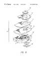
- FIG. 4is a perspective view of the preferred exemplary instrument in which the top portion has been removed to expose the cartridge rotor plate.
- FIG. 5is a view of the rotary drive mechanism and real time processing unit which is located at the bottom of the instrument as shown in FIGS. 2-4.
- FIG. 6is a detailed view of the cartridge rotor plate.
- FIG. 7is a detailed view of the cartridge rotor plate which shows the locking mechanism which holds the cartridge in place during rotation of the cartridge plate as well as the balancing mechanism which ensures that the rotor plate is balanced to ensure non-asymmetric rotation.
- FIG. 8is an exploded view of a preferred exemplary analytical cartridge which includes a test element which is designed to be used with a reflectance detector system.
- FIG. 9is a side view of the reflectance test cartridge shown in FIG. 8 .
- FIG. 10is a bottom view of the reflectance cartridge shown in FIG. 8 .
- FIG. 11is a perspective view of a preferred exemplary test cartridge which includes a pressure-operated reagent transport system and an electrochemical test element.
- FIG. 12is a view of the cartridge shown in FIG. 8 showing a bar code reading strip which is used by the instrument to provide tracking and control of cartridge processing.
- FIG. 13is an exploded view of the electrochemical cartridge shown in FIG. 11 .
- FIG. 14is an exploded view of the electrochemical cartridge of FIG. 11 showing the electrochemical test element.
- FIG. 15is a partially exploded view of an analytical cartridge in accordance with the present invention which includes a cuvette test element which allows transmittance-based detection by the analytical instrument.
- FIG. 16is a detailed view of the cuvette which forms part of the transmittance analytical test cartridge shown in FIG. 15 .
- FIG. 17is a sectional view of FIG. 16 which depicts the pathway of light through the cuvette detector.
- FIG. 18is a bottom view of the upper housing plate which is located on top of the cartridge rotor plate. This figure depicts a septum actuator, vent seal element and actuator mechanism which form part of the sample transport system which contact the cartridges during processing by the instrument. The figure also depicts the actuator mechanisms which actuate the reagent transport system in the cartridge.
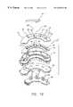
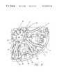
- FIG. 19is an exploded view of the optical detection unit which is located at a position within the analytical instrument below the cartridge rotor plate.
- FIG. 20shows the elements of the electrochemical detection system which are located in the lower housing of the preferred exemplary instrument.
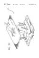
- FIG. 21is a more detailed view of FIG. 20 showing the electrochemical contact pins and actuator assembly.
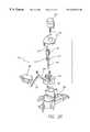
- FIG. 22shows the encoding assembly located in the bottom portion of the instrument which provides tracking and control of the cartridge rotor plate.
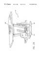
- FIG. 23is a perspective view of the bar code reader which is located in the top portion of the instrument.
- FIG. 24is an alternate perspective view of the bar code reader shown in FIG. 23 with the light-emitting diodes (LED) on one side being exposed.
- LEDlight-emitting diodes
- FIG. 25is a perspective view of the housing plates which surround the cartridge rotor plate.
- the housing platesinclude heating elements which are operated to maintain controlled temperature during processing of the cartridges.
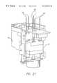
- FIG. 26is an exploded view of the preferred exemplary sample transport actuator system in accordance with the present invention.
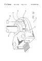
- FIG. 27is a perspective view of the assembled sample transport actuator.
- FIG. 28shows vent actuator block which forms part of the sample transport actuator mechanism.
- FIG. 29shows the preferred exemplary reagent pouch actuator and related actuating mechanism.
- FIG. 30is an exploded view of the reagent pouch actuator assembly shown in FIG. 29 .
- FIG. 31is a perspective view of the cartridge rotor plate wherein the platter caps have been removed to show the cartridge latching mechanism.
- FIG. 32is a detailed view of the sample cartridge ejection mechanism.
- a preferred exemplary analytical instrument in accordance with the present inventionis shown generally at 10 in FIG. 1 .
- the outer housing of the instrumentis shown in more detail in U.S. Pat. No. Design. 424,1956
- the instrumentis designed to receive and process self-contained analytical cartridges such as those shown generally at 12 .
- the cartridges 12include test elements which utilize reflectance, transmittance or electrochemistry.
- the transmittance type analytical cartridgeis shown in FIGS. 8-10 and 12 . This type of cartridge is also described in detail in international application No. PCT/US98/15616. This type of cartridge will also be described briefly below.
- FIGS. 11, 13 and 14The type of analytical cartridge which utilizes an electrochemical test element is shown in FIGS. 11, 13 and 14 . Such electrochemical test cartridges are also described in International patent application No. PCT/US99/0628. The electrochemical cartridge will also be briefly described below. The transmittance type analytical cartridge is shown in FIGS. 15-17. This type of cartridge is also described in detail in International patent application No. PCT/US99/01707.
- the analyzer 10includes an upper housing cover 14 and a lower housing cover 16 .
- a computer input/output pad or screen 18is located in the upper cover 14 to allow the operator of the instrument to view information and input.
- the housing cover 14further includes an inlet port 20 through which the cartridges 12 are inserted into the instrument.
- a central processing unitis located within the upper housing cover 14 .
- a disc inlet 22is provided for allowing the operator to insert floppy disks into the central processing unit to provide software updates as well as transport other data and information into and out of the central processing unit.
- the upper housing cover 14also includes a port and shelf 24 where a paper copy of report results and other data is made available to the operator.
- the analyzeris shown in FIGS. 2-4 with the housing covers and central processing unit removed.
- the instrumentincludes a cartridge carousel assembly shown generally at 26 , a detector assembly located below the cartridge carousel assembly 26 and shown generally at 28 and a tracking and control unit which is located in the bottom of the instrument and is shown generally at 30 .
- the tracking and control system 30includes two circuit boards 29 and 31 which are connected to the central processing unit and a real-time processor to provide overall tracking and control functions for the instrument.
- the cartridge carousel assemblyincludes a cartridge rotor plate 32 , a rotary drive mechanism 34 and sample/reagent actuators 36 .
- a retractable door 35is provided which can be lowered to allow cartridges 12 to be introduced into the rotor plate 32 .
- the rotary drive mechanism 34includes a motor and pulley assembly 38 which drives belt 40 and pulley 42 which is connected to driveshaft 44 .
- the cartridge rotor plate 32is connected to the driveshaft 44 .
- An encoding assembly 46is provided to track the position of the cartridge rotor plate 32 and provide outputs which are part of the tracking and control system which operate motor 38 to provide controlled stopping and rotation of cartridge rotor plate 32 at various times and at various speeds.
- the cartridge rotor plate 32includes a center 48 and a plurality of cartridge ports 50 which are located in spaced relation radially outward from the center 48 .
- the cartridge ports 50are shaped to receive the analytical cartridges which are shown in FIGS. 8-17.
- An exemplary cartridge 12is shown in position within the cartridge rotor plate 32 (see FIG. 6 ).
- the rotor plate 32includes locking tabs 52 which are located on either side of port 50 .
- the locking tabs 52engage the sides of cartridge 12 to lock it in place during centrifugation of the cartridges.
- the rotor plate 32further includes balance weights 54 which are connected to a support yoke 56 .
- the cartridge ports 50are divided into two sections. An outer cartridge dock 58 and an inner balance weight dock 60 .
- the balance weight 54 and yoke assembly 56are pushed via a yoke mounting track into the balance weight dock 60 .
- the movement of the balancing weight 54 and yoke 56 from the cartridge dock 58 into the balance weight dock 60is represented by arrow 62 in FIG. 7 .
- the yoke 56is held in place and guided by top plates 57 .
- the rotor plate 32is shown with the top plates 57 being removed.
- the cartridge 12As the cartridge 12 is moved into dock 58 , it contacts tabs 52 and pushes the tabs 52 outward.
- the tabs 52are connected to arms 53 .
- the arms 53include inner tabs 64 which are spring-biased inward by springs located between the arms at 55 in FIG. 31 . The springs are not shown.
- the tabsOnce the cartridge 12 reaches its final location in dock 58 , the tabs are spring-biased into locking engagement with indentations in the cartridge 12 .
- the inner tabs 64are located so that they do not interfere with movement of the weight 54 into the balance weight dock 60 .
- the balance weight 54 and yoke 56remain within the cartridge dock 58 during rotation of plate 32 .
- This counterbalance systemallows the operator to insert as few as one cartridge into the instrument for analysis or as many as six. An even larger number of cartridges can be inserted into the cartridge rotor plate if the number of ports is increased.
- the balance weight located in the port 50 which is adjacent to the cartridge 12(counterclockwise) is shown located within the balance weight dock 60 . Upon initial rotation, this particular counterweight will slide outward into the cartridge dock 58 to provide balancing of the plate 32 .
- the cartridges 12 which are processed by the analytical instrument of the present inventioncan be of at least three types.
- the first typeis shown at 66 in FIGS. 8-10 and 12 .
- the cartridge 66includes a body 68 , top plate 70 , label 72 and cover 74 .
- the concave curve in the cartridge body sidesmay be eliminated as shown in phantom at 75 in FIG. 10, if desired.
- the cartridgeincludes a sample metering/separation system which is shown at 76 in FIG. 8 .
- the sampleis introduced into the system 76 through sample introduction portion 78 .
- the systemalso includes a vent port 80 which is required for proper operation of the system.
- the system 76is designed to meter out an accurate sample aliquot when the cartridge is subjected to centrifugation.
- the system 76is designed to provide separation of solid components, such as blood cells, from the sample during centrifugation, if desired.
- the cartridge 66also includes a flexible septum 82 which forms an essential part of the cartridge's pressure-operated sample transport system.
- the analytical instrument of the present inventionincludes a sample transport actuator which compresses septum 82 in order to pressurize the system 76 and transport the previously-metered sample to the test element. The two basic steps of the analytical process are centrifugation of the cartridge to achieve metering and separation of the sample followed by pressurization of system via septum 82 to transport the sample to the test element.
- the test element for cartridge 66is reflectance reagent plate 84 which is held in place within the cartridge by retainer 86 . Pressurization of septum 82 transports the sample through system 76 into contact with the reagent plate 84 . The result is a detectable analytical property. This analytical property is measured by the analytical instrument, as will be described in more detail below, by focusing radiation of a selected wavelength onto plate 84 and measuring the amount of radiation which is reflected back to a detector. Both the radiation source and reflectance detector are located below the cartridge rotor plate 32 .
- FIGS. 11, 13 and 14A second type of analytical cartridge is shown at 88 in FIGS. 11, 13 and 14 .
- Cartridge 88is similar to cartridge 66 in that it requires centrifugation followed by pressurization in order to carry out analysis of a given sample. The principal differences are that the cartridge 88 includes a system for transporting reagent to the test element and, instead of using a reflectance test element, cartridge 88 utilizes an electrochemical measuring device.
- the electrochemical analytical cartridge 88includes a body 90 , top plate 92 , cover 94 and flexible septum 96 .
- the cartridge 88also includes a flexible reagent pouch 98 which is compressed and punctured by a reagent transport actuator to transport reagent to the electrochemical detector which is shown at 100 in FIG. 14 .
- cartridge 88also includes a label 104 .
- Both labels 104 on cartridge 88 and label 72 on cartridge 66preferably include a bar code which is shown at 106 in FIG. 12 . This bar code is read by the instrument to provide input of data which is specific to the particular cartridge. This information is used by the tracking and control system of the analytical instrument to coordinate the rotary drive mechanism for the cartridge rotor plate and the actuators which operate against the flexible septums and flexible reagent pouches.
- the electrochemical cartridge 88also includes a sample inlet port 108 and vent port 110 .
- the sample metering and transport systemis shown at 112 in FIG. 13 . This system typically does not include the plumbing required for separation of solid components from the sample because, in general, electrochemical tests do not require separation of solids from the sample. However, the system shown at 112 may be modified to provide sample separation, if desired.
- the cartridge cover 94is opened in order to allow the operator to place a sample into the cartridge through port 108 .
- the coveris then closed as shown in FIG. 12 and the cartridge inserted into one of the ports 50 in cartridge rotor plate 32 .
- the cartridgeis then centrifuged at sufficient speeds and for a sufficient time to meter out an accurate amount of sample within system 112 .
- Septum 82is then actuated to transport sample liquid to the electrochemical detector 100 .
- flexible reagent pouch 92is also compressed. Compression of flexible pouch 98 causes the pouch to be punctured and reagent to be transported to the electrochemical detector 100 .
- the instrumentincludes an electrochemical detector probes, which will be described in further detail below. The probes contact the electrochemical detector 100 to measure the results of electrochemical testing.
- FIGS. 15-17A third type of exemplary cartridge which is processed by the analytical instrument of the present invention is shown in FIGS. 15-17.
- This type of cartridgeis a transmittance-type analytical cartridge which is shown at 114 in FIG. 15 .
- the transmittance cartridge 114includes a cartridge body 116 , top plate 118 , cover 120 and septum 122 .
- the transmittance cartridge 114further includes a cuvette 124 which is held in place by retainer 126 .
- the cuvette 124is a test element which is capable of being exposed to spectral radiation in order to provide spectrophotometric test results.
- the cuvette 124is shown in more detail in FIGS. 16 and 17.
- the cuvette 124includes optical wings 128 and 130 which direct spectral radiation through the cuvette test zone or cell 132 as shown by phantom line 134 in FIG. 17 .
- the analytical instrument of the present inventionincludes a detector system which has a spectral radiation source shown schematically at 136 in FIG. 17 which is located below the cartridge rotor plate 32 .
- the spectral radiation sourcedirects a focused beam of radiation 134 up to wing 130 which in turn directs the beam through the cuvette test zone or test cell 132 to wing 128 and back down to a detector shown schematically in FIG. 17 at 138 .
- FIG. 18A bottom view of the upper portion 140 of the cartridge carousel assembly 26 is shown in FIG. 18 .
- the upper portion 140is also shown in place on instrument 10 in FIG. 2.
- a sample transport actuatoris shown at 144 in FIG. 2 and 141 in FIG. 26 .
- actuator 141includes a septum actuator rod 142 is provided which is movable into contact with the flexible septums on the analytical cartridges to move the septums from a relaxed position to one or more compressed positions to provide transport of metered and/or separated samples to the cartridge test element.
- a vent seal rod 146is also provided which is designed to contact and seal the cartridge vent which is shown at 80 in FIG. 8, 110 in FIG. 11 and not shown on the cartridge in FIG. 15 .
- the sample transport actuator mechanism 141includes a motor 143 , pusher cover 145 , vent block 147 , main pusher block 149 , vent block spring 151 and vent seal rod spring 155 .
- the vent seal rod 146includes a tip 163 .
- the block 149is moved up and down by motor 143 via drive shaft 165 .
- the vent seal rod tip 163extends below the tip of the septum actuator rod 142 .
- the vent seal rod tip 163contacts and seals the cartridge vent prior to the septum actuator rod 142 compressing the flexible septum. It is necessary that the cartridge vent be closed prior to compression of the flexible septum. Otherwise, adequate pressurization of the cartridge may not be achieved to provide desired sample transport.
- the sample transport actuator mechanism 141must also provide for retraction of vent seal rod 146 from its sealing position against the cartridge prior to retraction of the septum actuator rod 142 .
- vent seal rod 146By retracting the vent seal rod 146 first, pressure within the analytical cartridge is released uniformly. This eliminates the possibility of disturbing liquids within the cartridge plumbing due to premature movement of the flexible septum back to the septum's initial relaxed position.
- a wide variety of different possible mechanismsare possible to achieve this condition wherein the vent seal rod provides a seal prior to septum compression and releases the seal prior to septum relaxation.
- a solenoid-operated release systembe used as shown in FIGS. 26 and 27.
- This systememploys a solenoid 148 which operates a push lever 167 which is connected to seal rod 146 by lever spring 169 . Operation of solenoid 148 moves lever 167 which releases the vent seal rod 146 so that it moves upward in vent block 147 . Once the vent seal rod 146 is released, the main pusher block 149 is withdrawn to release the septum rod 142 from contact with the cartridge septum. To reset the vent seal, the vent seal rod 146 is moved to the position shown in FIG. 27, where a reset pin 177 is pushed against reset bar 179 .
- a reagent transport actuatoris shown generally at 183 in FIGS. 18, 29 and 30 .
- the reagent actuator 183includes a reagent pouch actuator rod 150 .
- the reagent actuator rod 150is controlled by actuator motor 152 .
- the rod 150 and actuator motor 152form a reagent actuator mechanism which moves the reagent pouch on the analytical cartridge from a relaxed position to one or more compressed positions.
- a tip 185is placed over the rod 150 .
- the tip 185is connected to a block 187 .
- a spring 189biases the tip 185 away from rod 150 . During compression of the reagent pouch, the spring 189 becomes slightly compressed as the tip 185 is seated against the rod 150 .
- a spike or other element in the cartridgepunctures the reagent cartridge to allow release and pressurized transport of the reagent.
- the spring 189provides a constant pressure bias against the pouch even as it is punctured and releases fluid.
- the reagent actuator rod 150 , septum actuator rod 142 and vent seal rod 146are all shown in their retracted position in FIG. 18 .
- the various rodsare moved into contact with the cartridges as controlled by the tracking and control system of the instrument. The system is coordinated so that the actuator rods only move into contact with a cartridge when the cartridge rotor plate 32 is stationary.
- additional reagent pouch actuators and associated actuator mechanismsmay be included in the instrument to handle cartridges which may have two or more reagent pouches which require simultaneous actuation.
- Ejection of cartridges 12 from rotor plate 32is accomplished by an ejection mechanism which is shown at 153 in FIGS. 18 and 32.
- the mechanism 153includes an ejection arm 154 , guide rod 155 and drive motor 156 .
- the actuator arm 154is shown in a retracted position.
- the actuator arm 154moves in the direction of arrow 157 .
- the ejection actuator arm 154is operated by motor mechanism 156 .
- the actuator arm 154ejects the cartridge 12 by first moving inner tabs 64 outward. Movement of inner tabs 64 outward also moves arms 53 and attached tabs 52 outward to release cartridge 12 .
- the actuator arm 154continues to move outward to move the counter weight 54 to the position shown in FIG. 7 and eject cartridge 12 .
- the tracking and control unit of the instrumentcontrols the ejection mechanism 153 and rotary drive mechanism 34 so that the cartridges are only ejected when they are located at ejection port 159 (see FIGS. 2 and 4 ).
- a magnetic mechanism 161is located adjacent to the ejector 153 .
- the magnet 161is used in combination with magnetic particles which may be included in the cartridges to provide mixing of reagents and samples within the cartridges as they pass by the magnet.
- a preferred exemplary optical detectoris shown at 158 in FIG. 19 .
- the optical detector 158is located directly below the cartridge carousel assembly 26 .
- the optical detector 158includes seven LED's 160 .
- the optical detector 158further includes collimator elements 164 and 166 which direct spectral radiation from the LED upward through the detector as represented by phantom line 168 . The radiation path for only the central LED is shown.
- the collimating elements 164 and 166direct the other LED beams in the same manner.
- the detector 158further includes a beam control plate 170 which includes six slits 172 and one smaller slit 162 .
- the slits 172 and 162further reduce the size of LED beams 168 so that the final radiation beams 168 which contacts the test element of the analytical cartridge has a small cross-sectional area.
- the test element of the analytical cartridgeis shown diagrammatically at 174 in FIG. 19 .
- the slit 162is smaller than the other slits and is designed for use with cartridges that include a cuvette.
- the test elementmay include either a reflectance test element or a transmittance test element (i.e., the cuvette 124 shown in FIGS. 16 and 17 ).
- the optical detector 158further includes a return beam detector plate 176 which includes four optical detector elements 178 .
- the return beam from analytical cartridge 174travels through openings 181 in beam control plate 170 .
- the path of the returning beam of transmitted or reflected spectral radiationis shown in phantom at 180 . Again, for simplicity, the return beam path 180 is shown for only one of the LED's 160 .
- the light-emitting diodes 160each have a different wavelength. For example, moving from right to left in FIG. 19, the light-emitting diodes will have wavelengths of 425 nanometers, 505 nanometers, 570 nanometers, 590 nanometers, 615 nanometers, and 655 nanometers.
- the LED 160 on the far leftis used for cuvette cartridges and preferably emits a wavelength of 570 nm. This range of LED wavelengths is preferred since it provides measurement beams ranging from near-ultraviolet through the visible spectrum to near-infrared wavelengths.
- a wide variety of LED combinationsis possible depending upon the types of tests being conducted.
- the tracking and control unitis programmed, depending upon the particular test cartridge being analyzed, to expose the cartridge to one or more of the LED wavelengths. In this way, a wide variety of spectrophotometric measurements can be made.
- the optical detector 158is arcuate in shape.
- the arcuate shape of the optical detector 158is matched to the arcuate path of the cartridges as they move during rotation of the cartridge rotor plate 32 . In this way, measurements may be taken when the cartridge is stationary or when the cartridge is moved past the detector during rotation of the rotor plate 32 .
- the instrumentmay be programmed so that multiple measurements of the test element 174 may be made as it moves past the optical detector slits 172 . In this way, measurements from one end of the test element to the other can be taken as the test element moves past a particular slit 172 .
- the cartridge test element 174may be held stationary over the optical detector 158 and time-dependent changes in spectral transmittance or reflectance may be measured. It is preferred that the cross-sectional area of slits 172 be substantially less than the cross-sectional area of the optically-accessible portion of the test element 174 present in the analytical cartridge. For example, the cross-sectional area of slit 172 should be at least one-tenth of the cross-sectional area of the optically-accessible portion of test element 174 . Test beams having cross-sectional areas which are on the order of one-hundredth of the cross-sectional area of the optically-accessible portion of the test element are also possible.
- a preferred exemplary electrochemical detectoris shown at 182 in FIGS. 20 and 21.
- the electrochemical detector 182is located directly below the cartridge carousel assembly 26 as shown in FIGS. 2 and 4.
- the electrochemical detector 182includes electrical contact probes 184 which are designed to be moved by actuator mechanism 186 into contact with the electrochemical detector 100 located on the bottom of electrochemical cartridge 88 (FIG. 14 ).
- the instrument tracking and control systemis set up so that the electrical probes 184 are only moved into position by actuator 182 when an electrochemical cartridge is being tested. Further, the instrument is programmed so that the electrical probes 184 are only moved into position when the cartridge is located over the electrochemical detector 182 and is stationary.
- the analytical instrumentwill preferably include a spindle positioning encoder which is shown at 188 in FIG. 22, and more generally at 46 in FIG. 5 .
- the encoderis connected to the circuit boards of the tracking and control unit 30 which are in turn connected with the central processing unit.
- the encoder 188is connected to spindle 44 which in turn is connected to the rotor plate 32 .
- a transparent optical disk 190is provided which has indexing marks 192 which include a home index mark 194 .
- a light source 196 with corresponding optical detector 198are provided to detect passage of the index marks past the optical detector.
- the combined light source and optical detector 196 and 198provides continual input to the real-time processing unit and central processor which allows accurate control of rotation speeds and radial location of cartridges, when they are located within the cartridge rotor plate.
- Other encoder systemsare possible provided that they are capable of providing the same tracking information which is input into the tracking and control system in order to accurately control rotation and positioning the cartridge rotor plate 32 .
- the analytical instrumentincludes a bar code reader which is shown at 200 in FIGS. 2-3 and 23 - 24 .
- the bar code reader 200scans arcuate bar codes 201 on the analytical cartridges to provide input into the tracking and control system regarding the type of cartridge and tests to be run (see FIG. 6 ).
- the bar code reader 200also reads a Z-shaped position calibration label 202 on the rotor plate 32 (FIG. 6 ).
- the bar code reader 200preferably utilizes a 1:1 ratio double-lens camera and a light source such as LED's 204 .
- the bar code readeralso includes a photodiode light detector 206 .
- the alternating light and dark segments of the bar code 201pass before the bar code reader 200 , they are illuminated by the light source 204 and projected onto the photodiode detector chip 206 as a series of light pulses.
- the detector chip 206is preferably a linear array of 128 photodiode elements oriented such that light reflected from each bar code element shines upon about three or more photodiode elements.
- the bar code reader 200is also adapted to scan the Z-shaped position calibration label 202 on the spinning rotor plate 32 .
- the bar code reader 200 in conjunction with the encoder 188provide input into the central processing unit and/or real-time processor which allows the position of the rotor plate to be accurately determined and controlled.
- the cartridge rotor platebe maintained at constant temperature. For many cartridges, test results will vary if the temperature is not kept constant. In addition, some tests must be conducted at elevated temperatures. Accordingly, it is preferred that two heating plates 210 and 212 be located on either side of the cartridge rotor plate 32 as shown in FIG. 25 .
- the heater plates or platensare preferably electrically heated. However, other types of temperature control systems may be used.
- the spinning of the rotor plate at relatively high speedse.g. 1500 rpm) facilitates heating because of the uniform and constant mixing of air and heat generated by the rotor.
Landscapes
- Physics & Mathematics (AREA)
- Health & Medical Sciences (AREA)
- Life Sciences & Earth Sciences (AREA)
- Chemical & Material Sciences (AREA)
- Analytical Chemistry (AREA)
- Biochemistry (AREA)
- General Health & Medical Sciences (AREA)
- General Physics & Mathematics (AREA)
- Immunology (AREA)
- Pathology (AREA)
- Automatic Analysis And Handling Materials Therefor (AREA)
Abstract
Description
Claims (13)
Priority Applications (3)
| Application Number | Priority Date | Filing Date | Title |
|---|---|---|---|
| US09/248,737US6348176B1 (en) | 1999-02-11 | 1999-02-11 | Cartridge-based analytical instrument using centrifugal force/pressure for metering/transport of fluids |
| AU33591/00AAU3359100A (en) | 1999-02-11 | 2000-02-09 | Cartridge-based analytical instrument |
| PCT/US2000/003367WO2000047977A1 (en) | 1999-02-11 | 2000-02-09 | Cartridge-based analytical instrument |
Applications Claiming Priority (1)
| Application Number | Priority Date | Filing Date | Title |
|---|---|---|---|
| US09/248,737US6348176B1 (en) | 1999-02-11 | 1999-02-11 | Cartridge-based analytical instrument using centrifugal force/pressure for metering/transport of fluids |
Publications (1)
| Publication Number | Publication Date |
|---|---|
| US6348176B1true US6348176B1 (en) | 2002-02-19 |
Family
ID=22940455
Family Applications (1)
| Application Number | Title | Priority Date | Filing Date |
|---|---|---|---|
| US09/248,737Expired - Fee RelatedUS6348176B1 (en) | 1999-02-11 | 1999-02-11 | Cartridge-based analytical instrument using centrifugal force/pressure for metering/transport of fluids |
Country Status (1)
| Country | Link |
|---|---|
| US (1) | US6348176B1 (en) |
Cited By (29)
| Publication number | Priority date | Publication date | Assignee | Title |
|---|---|---|---|---|
| US6593143B1 (en)* | 2000-02-29 | 2003-07-15 | Agilent Technologies, Inc. | Centrifuge system with contactless regulation of chemical-sample temperature using eddy currents |
| US20040197233A1 (en)* | 2003-04-02 | 2004-10-07 | Yoshihiro Nagaoka | Chemical analyzer and structure for chemical analysis |
| US20050170515A1 (en)* | 2004-02-04 | 2005-08-04 | Hach Company | Analytical rotor system with an analytical signal path |
| US20050170513A1 (en)* | 2004-02-04 | 2005-08-04 | Hach Company | Analytical rotor system for titration testing |
| US20050169804A1 (en)* | 2004-02-04 | 2005-08-04 | Hach Company | User-configurable analytical rotor system |
| US20050169805A1 (en)* | 2004-02-04 | 2005-08-04 | Hach Company | Analytical rotor system with a sample chamber |
| WO2005077541A1 (en)* | 2004-02-04 | 2005-08-25 | Hach Company | User-configurable analytical rotor system |
| US20050221281A1 (en)* | 2003-01-08 | 2005-10-06 | Ho Winston Z | Self-contained microfluidic biochip and apparatus |
| US20060133958A1 (en)* | 2004-12-22 | 2006-06-22 | Wen-Pin Hsieh | Fluid analytical devices |
| US20060141021A1 (en)* | 2004-12-29 | 2006-06-29 | Industrial Technology Research | Polymeric microspheres and method for preparing the same |
| US20070012683A1 (en)* | 2005-05-06 | 2007-01-18 | Applera Corporation | Device including inductively heatable fluid retainment region, and method |
| US20070117200A1 (en)* | 1997-03-28 | 2007-05-24 | Applera Corporation | Thermal cycler for PCR |
| EP1862792A2 (en) | 2006-05-31 | 2007-12-05 | Ushiodenki Kabushiki Kaisha | Biochemical analysis device |
| US20100184228A1 (en)* | 2007-07-27 | 2010-07-22 | Panasonic Corporation | Device for analysis and analyzing apparatus and method using the device |
| CN102004159A (en)* | 2009-09-01 | 2011-04-06 | 优志旺电机株式会社 | Clinical laboratory test apparatus |
| US20110085950A1 (en)* | 2009-10-08 | 2011-04-14 | Samsung Electronics Co., Ltd. | Centrifugal force based microfluidic system and bio cartridge for the microfluidic system |
| JP2014530358A (en)* | 2011-09-25 | 2014-11-17 | セラノス, インコーポレイテッド | System and method for multiplex analysis |
| US20160139138A1 (en)* | 2007-10-02 | 2016-05-19 | Theranos, Inc. | Modular point-of-care devices, systems, and uses thereof |
| US9464981B2 (en) | 2011-01-21 | 2016-10-11 | Theranos, Inc. | Systems and methods for sample use maximization |
| US9592508B2 (en) | 2011-09-25 | 2017-03-14 | Theranos, Inc. | Systems and methods for fluid handling |
| US9632102B2 (en) | 2011-09-25 | 2017-04-25 | Theranos, Inc. | Systems and methods for multi-purpose analysis |
| US9645143B2 (en) | 2011-09-25 | 2017-05-09 | Theranos, Inc. | Systems and methods for multi-analysis |
| US9664702B2 (en) | 2011-09-25 | 2017-05-30 | Theranos, Inc. | Fluid handling apparatus and configurations |
| US10012664B2 (en) | 2011-09-25 | 2018-07-03 | Theranos Ip Company, Llc | Systems and methods for fluid and component handling |
| US10180248B2 (en) | 2015-09-02 | 2019-01-15 | ProPhotonix Limited | LED lamp with sensing capabilities |
| US10422806B1 (en) | 2013-07-25 | 2019-09-24 | Theranos Ip Company, Llc | Methods for improving assays of biological samples |
| US10920284B2 (en) | 2014-09-04 | 2021-02-16 | Labrador Diagnostics Llc | Pathogen and antimicrobial resistance testing |
| JP2021514705A (en)* | 2018-02-26 | 2021-06-17 | ゼネラル・エレクトリック・カンパニイ | Systems and methods for electrical pulse-based activation of biological samples |
| US11162936B2 (en) | 2011-09-13 | 2021-11-02 | Labrador Diagnostics Llc | Systems and methods for multi-analysis |
Citations (72)
| Publication number | Priority date | Publication date | Assignee | Title |
|---|---|---|---|---|
| US3555284A (en) | 1968-12-18 | 1971-01-12 | Norman G Anderson | Multistation, single channel analytical photometer and method of use |
| US3586484A (en) | 1969-05-23 | 1971-06-22 | Atomic Energy Commission | Multistation analytical photometer and method of use |
| US3684450A (en) | 1970-09-14 | 1972-08-15 | Stanford L Adler | Automatic apparatus and method for determining the packed cell volume of whole blood |
| US4284602A (en)* | 1979-12-10 | 1981-08-18 | Immutron, Inc. | Integrated fluid manipulator |
| US4309384A (en) | 1980-04-04 | 1982-01-05 | Ernest Trod | Chemical analysis cuvette |
| US4390499A (en)* | 1981-08-13 | 1983-06-28 | International Business Machines Corporation | Chemical analysis system including a test package and rotor combination |
| US4412973A (en) | 1980-12-15 | 1983-11-01 | Jean Guigan | Autonomous simultaneous analysis apparatus and a method of using it |
| EP0160282A2 (en) | 1984-05-03 | 1985-11-06 | Abbott Laboratories | Processor card for centrifuge |
| US4676952A (en)* | 1983-04-25 | 1987-06-30 | Boehringer Mannheim Gmbh | Photometric analysis apparatus for a liquid |
| US4690801A (en) | 1986-06-03 | 1987-09-01 | Allelix Inc. | Device for performing enzyme immunoassays |
| US4690899A (en)* | 1984-07-06 | 1987-09-01 | Boehringer Mannheim Gmbh | Process and device for carrying out analytical determinations |
| US4708940A (en) | 1982-03-10 | 1987-11-24 | Hitachi, Ltd. | Method and apparatus for clinical analysis |
| US4740472A (en) | 1985-08-05 | 1988-04-26 | The United States Of America As Represented By The United States Department Of Energy | Method and apparatus for automated processing and aliquoting of whole blood samples for analysis in a centrifugal fast analyzer |
| US4777141A (en) | 1984-11-27 | 1988-10-11 | Fisher Scientific Company | Instrument for measuring coagulation parameters and method of use |
| US4788154A (en) | 1985-12-20 | 1988-11-29 | Jean Guigan | Method and apparatus for obtaining and delivering a predetermined quantity of plasma from a blood sample for analysis purposes |
| US4814144A (en) | 1980-11-25 | 1989-03-21 | Boehringer Mannheim Gmbh | Centrifugal analyzer rotor unit and insert elements |
| US4814282A (en) | 1984-05-03 | 1989-03-21 | Abbott Laboratories | Centrifuge for two-dimensional centrifugation |
| US4837160A (en) | 1983-10-28 | 1989-06-06 | Gamma Biologicals, Inc. | Biological fluid assay system and method |
| US4865810A (en) | 1986-09-25 | 1989-09-12 | Kis Photo Industrie | Centrifuge for performing medical analyses |
| US4883763A (en) | 1984-05-03 | 1989-11-28 | Abbott Laboratories | Sample processor card for centrifuge |
| US4898832A (en) | 1981-09-01 | 1990-02-06 | Boehringer Mannheim Gmbh | Process for carrying out analytical determinations and means for carrying out this process |
| US4902479A (en) | 1983-11-07 | 1990-02-20 | Fisher Scientific Company | Centrifugal analyzer rotor |
| US4937050A (en) | 1983-06-16 | 1990-06-26 | Boehringer Mannheim Gmbh | Apparatus for the evaluation of a test carrier for the analytical determination of components of a body fluid |
| US4940527A (en) | 1987-06-01 | 1990-07-10 | Abbott Laboratories | Two-part test cartridge for centrifuge |
| US4956148A (en) | 1987-04-22 | 1990-09-11 | Abbott Laboratories | Locking rack and disposable sample cartridge |
| US4970053A (en) | 1986-07-11 | 1990-11-13 | Beckman Instruments, Inc. | Reagent cartridge |
| US5001417A (en) | 1987-06-01 | 1991-03-19 | Abbott Laboratories | Apparatus for measuring electrolytes utilizing optical signals related to the concentration of the electrolytes |
| US5035861A (en) | 1987-04-22 | 1991-07-30 | Abbott Laboratories | Locking rack and disposable sample cartridge |
| US5061446A (en) | 1988-07-28 | 1991-10-29 | Jean Guigan | Device for performing biological analyses by immunoenzymatic detection of antibodies or antigens in a serum |
| US5061381A (en) | 1990-06-04 | 1991-10-29 | Abaxis, Inc. | Apparatus and method for separating cells from biological fluids |
| US5077013A (en) | 1988-07-28 | 1991-12-31 | Jean Guigan | Miniature laboratory for performing biological analyses by chemical reaction on a sample of blood |
| US5089417A (en) | 1987-07-01 | 1992-02-18 | Miles Inc. | Fluid separation and processing device |
| US5110552A (en) | 1988-07-28 | 1992-05-05 | Jean Guigan | Apparatus for performing biological analyses by chemical reaction on a serum |
| US5122284A (en) | 1990-06-04 | 1992-06-16 | Abaxis, Inc. | Apparatus and method for optically analyzing biological fluids |
| US5149501A (en) | 1990-01-29 | 1992-09-22 | Cirrus Diagnostics, Inc. | Multichambered container and instrument for performing diagnostic tests |
| US5160702A (en) | 1989-01-17 | 1992-11-03 | Molecular Devices Corporation | Analyzer with improved rotor structure |
| US5171533A (en) | 1989-07-31 | 1992-12-15 | Fine Richard A | Biological assay cassette and method for making same |
| US5186896A (en)* | 1989-06-01 | 1993-02-16 | Behringwerke Aktiengesellschaft | Cuvette rotor |
| US5186844A (en) | 1991-04-01 | 1993-02-16 | Abaxis, Inc. | Apparatus and method for continuous centrifugal blood cell separation |
| US5192506A (en) | 1991-02-14 | 1993-03-09 | P B Diagnostic Systems, Inc. | Incubator port closure for automated assay system |
| US5207634A (en) | 1991-01-23 | 1993-05-04 | Biotope, Inc. | Self-balancing apparatus and method for a centrifuge device |
| US5242606A (en) | 1990-06-04 | 1993-09-07 | Abaxis, Incorporated | Sample metering port for analytical rotor having overflow chamber |
| US5254479A (en) | 1991-12-19 | 1993-10-19 | Eastman Kodak Company | Methods for preventing air injection into a detection chamber supplied with injected liquid |
| US5256376A (en) | 1991-09-12 | 1993-10-26 | Medical Laboratory Automation, Inc. | Agglutination detection apparatus |
| US5290518A (en) | 1992-08-17 | 1994-03-01 | Eastman Kodak Company | Flexible extraction device with burstable sidewall |
| US5296911A (en) | 1992-07-16 | 1994-03-22 | Schiapparelli Biosystems, Inc. | Optical test system for a chemical analyzer |
| US5304348A (en) | 1992-02-11 | 1994-04-19 | Abaxis, Inc. | Reagent container for analytical rotor |
| US5314825A (en) | 1992-07-16 | 1994-05-24 | Schiapparelli Biosystems, Inc. | Chemical analyzer |
| US5320808A (en) | 1988-08-02 | 1994-06-14 | Abbott Laboratories | Reaction cartridge and carousel for biological sample analyzer |
| US5403415A (en) | 1993-11-17 | 1995-04-04 | Abaxis, Inc. | Method and device for ultrasonic welding |
| US5409665A (en) | 1993-09-01 | 1995-04-25 | Abaxis, Inc. | Simultaneous cuvette filling with means to isolate cuvettes |
| US5416026A (en) | 1993-10-04 | 1995-05-16 | I-Stat Corporation | Method for detecting the change in an analyte due to hemolysis in a fluid sample |
| US5427915A (en) | 1989-06-15 | 1995-06-27 | Biocircuits Corporation | Multi-optical detection system |
| US5439645A (en) | 1993-01-25 | 1995-08-08 | Coulter Corporation | Apparatus for automatically, selectively handling multiple, randomly associated hematological samples |
| US5447440A (en) | 1993-10-28 | 1995-09-05 | I-Stat Corporation | Apparatus for assaying viscosity changes in fluid samples and method of conducting same |
| US5449621A (en) | 1989-07-31 | 1995-09-12 | Biotope, Inc. | Method for measuring specific binding assays |
| US5472603A (en) | 1992-04-02 | 1995-12-05 | Abaxis, Inc. | Analytical rotor with dye mixing chamber |
| US5478750A (en) | 1993-03-31 | 1995-12-26 | Abaxis, Inc. | Methods for photometric analysis |
| US5522255A (en)* | 1993-08-31 | 1996-06-04 | Boehringer Mannheim Corporation | Fluid dose, flow and coagulation sensor for medical instrument |
| US5526111A (en)* | 1993-08-31 | 1996-06-11 | Boehringer Mannheim Corporation | Method and apparatus for calculating a coagulation characteristic of a sample of blood a blood fraction or a control |
| US5525304A (en) | 1994-06-24 | 1996-06-11 | Pasteur Sanofi Diagnostics | Apparatus for automated chemical analysis with variable reagents |
| US5578269A (en) | 1993-06-11 | 1996-11-26 | Ortho Diagnostic Systems Inc. | Automated blood analysis system with an integral centrifuge |
| US5589399A (en) | 1994-10-21 | 1996-12-31 | First Medical, Inc. | System and method for plasma separation and measurement |
| US5627041A (en) | 1994-09-02 | 1997-05-06 | Biometric Imaging, Inc. | Disposable cartridge for an assay of a biological sample |
| US5639428A (en) | 1994-07-19 | 1997-06-17 | Becton Dickinson And Company | Method and apparatus for fully automated nucleic acid amplification, nucleic acid assay and immunoassay |
| US5646049A (en) | 1992-03-27 | 1997-07-08 | Abbott Laboratories | Scheduling operation of an automated analytical system |
| US5672317A (en) | 1995-04-19 | 1997-09-30 | Roche Diagnostics Systems, Inc. | Analyzer with fixed position bar code reader |
| US5814279A (en) | 1995-02-03 | 1998-09-29 | Fresenius Ag | Centrifuge having marker elements |
| US5916522A (en)* | 1997-08-07 | 1999-06-29 | Careside, Inc. | Electrochemical analytical cartridge |
| US5919711A (en)* | 1997-08-07 | 1999-07-06 | Careside, Inc. | Analytical cartridge |
| US6002475A (en)* | 1998-01-28 | 1999-12-14 | Careside, Inc. | Spectrophotometric analytical cartridge |
| US6124585A (en)* | 1998-10-27 | 2000-09-26 | Umm Electronics, Inc. | Apparatus for measuring the reflectance of strips having non-uniform color |
- 1999
- 1999-02-11USUS09/248,737patent/US6348176B1/ennot_activeExpired - Fee Related
Patent Citations (74)
| Publication number | Priority date | Publication date | Assignee | Title |
|---|---|---|---|---|
| US3555284A (en) | 1968-12-18 | 1971-01-12 | Norman G Anderson | Multistation, single channel analytical photometer and method of use |
| US3586484A (en) | 1969-05-23 | 1971-06-22 | Atomic Energy Commission | Multistation analytical photometer and method of use |
| US3684450A (en) | 1970-09-14 | 1972-08-15 | Stanford L Adler | Automatic apparatus and method for determining the packed cell volume of whole blood |
| US4284602A (en)* | 1979-12-10 | 1981-08-18 | Immutron, Inc. | Integrated fluid manipulator |
| US4309384A (en) | 1980-04-04 | 1982-01-05 | Ernest Trod | Chemical analysis cuvette |
| US4814144A (en) | 1980-11-25 | 1989-03-21 | Boehringer Mannheim Gmbh | Centrifugal analyzer rotor unit and insert elements |
| US4412973A (en) | 1980-12-15 | 1983-11-01 | Jean Guigan | Autonomous simultaneous analysis apparatus and a method of using it |
| US4390499A (en)* | 1981-08-13 | 1983-06-28 | International Business Machines Corporation | Chemical analysis system including a test package and rotor combination |
| US4898832A (en) | 1981-09-01 | 1990-02-06 | Boehringer Mannheim Gmbh | Process for carrying out analytical determinations and means for carrying out this process |
| US4708940A (en) | 1982-03-10 | 1987-11-24 | Hitachi, Ltd. | Method and apparatus for clinical analysis |
| US4676952A (en)* | 1983-04-25 | 1987-06-30 | Boehringer Mannheim Gmbh | Photometric analysis apparatus for a liquid |
| US4937050A (en) | 1983-06-16 | 1990-06-26 | Boehringer Mannheim Gmbh | Apparatus for the evaluation of a test carrier for the analytical determination of components of a body fluid |
| US4837160A (en) | 1983-10-28 | 1989-06-06 | Gamma Biologicals, Inc. | Biological fluid assay system and method |
| US4902479A (en) | 1983-11-07 | 1990-02-20 | Fisher Scientific Company | Centrifugal analyzer rotor |
| US4814282A (en) | 1984-05-03 | 1989-03-21 | Abbott Laboratories | Centrifuge for two-dimensional centrifugation |
| EP0160282A2 (en) | 1984-05-03 | 1985-11-06 | Abbott Laboratories | Processor card for centrifuge |
| US4883763A (en) | 1984-05-03 | 1989-11-28 | Abbott Laboratories | Sample processor card for centrifuge |
| US4690899A (en)* | 1984-07-06 | 1987-09-01 | Boehringer Mannheim Gmbh | Process and device for carrying out analytical determinations |
| US4777141A (en) | 1984-11-27 | 1988-10-11 | Fisher Scientific Company | Instrument for measuring coagulation parameters and method of use |
| US4740472A (en) | 1985-08-05 | 1988-04-26 | The United States Of America As Represented By The United States Department Of Energy | Method and apparatus for automated processing and aliquoting of whole blood samples for analysis in a centrifugal fast analyzer |
| US4788154A (en) | 1985-12-20 | 1988-11-29 | Jean Guigan | Method and apparatus for obtaining and delivering a predetermined quantity of plasma from a blood sample for analysis purposes |
| US4690801A (en) | 1986-06-03 | 1987-09-01 | Allelix Inc. | Device for performing enzyme immunoassays |
| US4970053A (en) | 1986-07-11 | 1990-11-13 | Beckman Instruments, Inc. | Reagent cartridge |
| US4865810A (en) | 1986-09-25 | 1989-09-12 | Kis Photo Industrie | Centrifuge for performing medical analyses |
| US5035861A (en) | 1987-04-22 | 1991-07-30 | Abbott Laboratories | Locking rack and disposable sample cartridge |
| US4956148A (en) | 1987-04-22 | 1990-09-11 | Abbott Laboratories | Locking rack and disposable sample cartridge |
| US5001417A (en) | 1987-06-01 | 1991-03-19 | Abbott Laboratories | Apparatus for measuring electrolytes utilizing optical signals related to the concentration of the electrolytes |
| US4940527A (en) | 1987-06-01 | 1990-07-10 | Abbott Laboratories | Two-part test cartridge for centrifuge |
| US5089417A (en) | 1987-07-01 | 1992-02-18 | Miles Inc. | Fluid separation and processing device |
| US5061446A (en) | 1988-07-28 | 1991-10-29 | Jean Guigan | Device for performing biological analyses by immunoenzymatic detection of antibodies or antigens in a serum |
| US5077013A (en) | 1988-07-28 | 1991-12-31 | Jean Guigan | Miniature laboratory for performing biological analyses by chemical reaction on a sample of blood |
| US5110552A (en) | 1988-07-28 | 1992-05-05 | Jean Guigan | Apparatus for performing biological analyses by chemical reaction on a serum |
| US5320808A (en) | 1988-08-02 | 1994-06-14 | Abbott Laboratories | Reaction cartridge and carousel for biological sample analyzer |
| US5160702A (en) | 1989-01-17 | 1992-11-03 | Molecular Devices Corporation | Analyzer with improved rotor structure |
| US5186896A (en)* | 1989-06-01 | 1993-02-16 | Behringwerke Aktiengesellschaft | Cuvette rotor |
| US5427915A (en) | 1989-06-15 | 1995-06-27 | Biocircuits Corporation | Multi-optical detection system |
| US5171533A (en) | 1989-07-31 | 1992-12-15 | Fine Richard A | Biological assay cassette and method for making same |
| US5449621A (en) | 1989-07-31 | 1995-09-12 | Biotope, Inc. | Method for measuring specific binding assays |
| US5149501A (en) | 1990-01-29 | 1992-09-22 | Cirrus Diagnostics, Inc. | Multichambered container and instrument for performing diagnostic tests |
| US5061381A (en) | 1990-06-04 | 1991-10-29 | Abaxis, Inc. | Apparatus and method for separating cells from biological fluids |
| US5122284A (en) | 1990-06-04 | 1992-06-16 | Abaxis, Inc. | Apparatus and method for optically analyzing biological fluids |
| US5242606A (en) | 1990-06-04 | 1993-09-07 | Abaxis, Incorporated | Sample metering port for analytical rotor having overflow chamber |
| US5207634A (en) | 1991-01-23 | 1993-05-04 | Biotope, Inc. | Self-balancing apparatus and method for a centrifuge device |
| US5376063A (en) | 1991-01-23 | 1994-12-27 | Boehringer Mannheim Corporation | Self-balancing apparatus and method for a centrifuge device |
| US5192506A (en) | 1991-02-14 | 1993-03-09 | P B Diagnostic Systems, Inc. | Incubator port closure for automated assay system |
| US5186844A (en) | 1991-04-01 | 1993-02-16 | Abaxis, Inc. | Apparatus and method for continuous centrifugal blood cell separation |
| US5256376A (en) | 1991-09-12 | 1993-10-26 | Medical Laboratory Automation, Inc. | Agglutination detection apparatus |
| US5254479A (en) | 1991-12-19 | 1993-10-19 | Eastman Kodak Company | Methods for preventing air injection into a detection chamber supplied with injected liquid |
| US5304348A (en) | 1992-02-11 | 1994-04-19 | Abaxis, Inc. | Reagent container for analytical rotor |
| US5457053A (en) | 1992-02-11 | 1995-10-10 | Abaxis, Inc. | Reagent container for analytical rotor |
| US5646049A (en) | 1992-03-27 | 1997-07-08 | Abbott Laboratories | Scheduling operation of an automated analytical system |
| US5472603A (en) | 1992-04-02 | 1995-12-05 | Abaxis, Inc. | Analytical rotor with dye mixing chamber |
| US5314825A (en) | 1992-07-16 | 1994-05-24 | Schiapparelli Biosystems, Inc. | Chemical analyzer |
| US5296911A (en) | 1992-07-16 | 1994-03-22 | Schiapparelli Biosystems, Inc. | Optical test system for a chemical analyzer |
| US5290518A (en) | 1992-08-17 | 1994-03-01 | Eastman Kodak Company | Flexible extraction device with burstable sidewall |
| US5439645A (en) | 1993-01-25 | 1995-08-08 | Coulter Corporation | Apparatus for automatically, selectively handling multiple, randomly associated hematological samples |
| US5478750A (en) | 1993-03-31 | 1995-12-26 | Abaxis, Inc. | Methods for photometric analysis |
| US5578269A (en) | 1993-06-11 | 1996-11-26 | Ortho Diagnostic Systems Inc. | Automated blood analysis system with an integral centrifuge |
| US5522255A (en)* | 1993-08-31 | 1996-06-04 | Boehringer Mannheim Corporation | Fluid dose, flow and coagulation sensor for medical instrument |
| US5526111A (en)* | 1993-08-31 | 1996-06-11 | Boehringer Mannheim Corporation | Method and apparatus for calculating a coagulation characteristic of a sample of blood a blood fraction or a control |
| US5409665A (en) | 1993-09-01 | 1995-04-25 | Abaxis, Inc. | Simultaneous cuvette filling with means to isolate cuvettes |
| US5416026A (en) | 1993-10-04 | 1995-05-16 | I-Stat Corporation | Method for detecting the change in an analyte due to hemolysis in a fluid sample |
| US5447440A (en) | 1993-10-28 | 1995-09-05 | I-Stat Corporation | Apparatus for assaying viscosity changes in fluid samples and method of conducting same |
| US5403415A (en) | 1993-11-17 | 1995-04-04 | Abaxis, Inc. | Method and device for ultrasonic welding |
| US5525304A (en) | 1994-06-24 | 1996-06-11 | Pasteur Sanofi Diagnostics | Apparatus for automated chemical analysis with variable reagents |
| US5639428A (en) | 1994-07-19 | 1997-06-17 | Becton Dickinson And Company | Method and apparatus for fully automated nucleic acid amplification, nucleic acid assay and immunoassay |
| US5627041A (en) | 1994-09-02 | 1997-05-06 | Biometric Imaging, Inc. | Disposable cartridge for an assay of a biological sample |
| US5589399A (en) | 1994-10-21 | 1996-12-31 | First Medical, Inc. | System and method for plasma separation and measurement |
| US5814279A (en) | 1995-02-03 | 1998-09-29 | Fresenius Ag | Centrifuge having marker elements |
| US5672317A (en) | 1995-04-19 | 1997-09-30 | Roche Diagnostics Systems, Inc. | Analyzer with fixed position bar code reader |
| US5916522A (en)* | 1997-08-07 | 1999-06-29 | Careside, Inc. | Electrochemical analytical cartridge |
| US5919711A (en)* | 1997-08-07 | 1999-07-06 | Careside, Inc. | Analytical cartridge |
| US6002475A (en)* | 1998-01-28 | 1999-12-14 | Careside, Inc. | Spectrophotometric analytical cartridge |
| US6124585A (en)* | 1998-10-27 | 2000-09-26 | Umm Electronics, Inc. | Apparatus for measuring the reflectance of strips having non-uniform color |
Cited By (74)
| Publication number | Priority date | Publication date | Assignee | Title |
|---|---|---|---|---|
| US20080314431A1 (en)* | 1997-03-28 | 2008-12-25 | Applied Biosystems, Inc. | Thermal cycler for PCR |
| US8246243B2 (en) | 1997-03-28 | 2012-08-21 | Applied Biosystems, Llc | Thermal cycler for PCR |
| US8685717B2 (en) | 1997-03-28 | 2014-04-01 | Applied Biosystems, Llc | Thermal cycler for PCR |
| US9044753B2 (en) | 1997-03-28 | 2015-06-02 | Applied Biosystems, Llc | Thermal cycler for PCR |
| US20070113880A1 (en)* | 1997-03-28 | 2007-05-24 | Applera Corporation | Thermal cycler for PCR |
| US20070117200A1 (en)* | 1997-03-28 | 2007-05-24 | Applera Corporation | Thermal cycler for PCR |
| US20100173400A1 (en)* | 1997-03-28 | 2010-07-08 | Life Technologies Corporation | Thermal Cycler for PCR |
| US9776187B2 (en) | 1997-03-28 | 2017-10-03 | Applied Biosystems, Llc | Thermal cycler for PCR |
| US6593143B1 (en)* | 2000-02-29 | 2003-07-15 | Agilent Technologies, Inc. | Centrifuge system with contactless regulation of chemical-sample temperature using eddy currents |
| US20050221281A1 (en)* | 2003-01-08 | 2005-10-06 | Ho Winston Z | Self-contained microfluidic biochip and apparatus |
| EP1464398A3 (en)* | 2003-04-02 | 2005-11-16 | Hitachi High-Technologies Corporation | Chemical analyzer and structure for chemical analysis |
| US20040197233A1 (en)* | 2003-04-02 | 2004-10-07 | Yoshihiro Nagaoka | Chemical analyzer and structure for chemical analysis |
| WO2005077541A1 (en)* | 2004-02-04 | 2005-08-25 | Hach Company | User-configurable analytical rotor system |
| US20050169805A1 (en)* | 2004-02-04 | 2005-08-04 | Hach Company | Analytical rotor system with a sample chamber |
| US20050169804A1 (en)* | 2004-02-04 | 2005-08-04 | Hach Company | User-configurable analytical rotor system |
| US20050170513A1 (en)* | 2004-02-04 | 2005-08-04 | Hach Company | Analytical rotor system for titration testing |
| US20050170515A1 (en)* | 2004-02-04 | 2005-08-04 | Hach Company | Analytical rotor system with an analytical signal path |
| US20060133958A1 (en)* | 2004-12-22 | 2006-06-22 | Wen-Pin Hsieh | Fluid analytical devices |
| US7320776B2 (en) | 2004-12-22 | 2008-01-22 | Industrial Technology Research Institute | Fluid analytical devices |
| US20060141021A1 (en)* | 2004-12-29 | 2006-06-29 | Industrial Technology Research | Polymeric microspheres and method for preparing the same |
| US20070012683A1 (en)* | 2005-05-06 | 2007-01-18 | Applera Corporation | Device including inductively heatable fluid retainment region, and method |
| US7446288B2 (en) | 2005-05-06 | 2008-11-04 | Applied Biosystems Inc. | Device including inductively heatable fluid retainment region, and method |
| EP1862792A2 (en) | 2006-05-31 | 2007-12-05 | Ushiodenki Kabushiki Kaisha | Biochemical analysis device |
| EP1862792A3 (en)* | 2006-05-31 | 2009-12-30 | Ushiodenki Kabushiki Kaisha | Biochemical analysis device |
| US20070280854A1 (en)* | 2006-05-31 | 2007-12-06 | Ushiodenki Kabushiki Kaisha | Biochemical analysis device |
| US20100184228A1 (en)* | 2007-07-27 | 2010-07-22 | Panasonic Corporation | Device for analysis and analyzing apparatus and method using the device |
| US7897398B2 (en)* | 2007-07-27 | 2011-03-01 | Panasonic Corporation | Centrifugal analysis device with improved mixing and method using the device |
| US11366106B2 (en) | 2007-10-02 | 2022-06-21 | Labrador Diagnostics Llc | Modular point-of-care devices, systems, and uses thereof |
| US11092593B2 (en) | 2007-10-02 | 2021-08-17 | Labrador Diagnostics Llc | Modular point-of-care devices, systems, and uses thereof |
| US20160139138A1 (en)* | 2007-10-02 | 2016-05-19 | Theranos, Inc. | Modular point-of-care devices, systems, and uses thereof |
| US10670588B2 (en) | 2007-10-02 | 2020-06-02 | Theranos Ip Company, Llc | Modular point-of-care devices, systems, and uses thereof |
| US9581588B2 (en) | 2007-10-02 | 2017-02-28 | Theranos, Inc. | Modular point-of-care devices, systems, and uses thereof |
| US9588109B2 (en)* | 2007-10-02 | 2017-03-07 | Theranos, Inc. | Modular point-of-care devices, systems, and uses thereof |
| US11199538B2 (en) | 2007-10-02 | 2021-12-14 | Labrador Diagnostics Llc | Modular point-of-care devices, systems, and uses thereof |
| US10634667B2 (en) | 2007-10-02 | 2020-04-28 | Theranos Ip Company, Llc | Modular point-of-care devices, systems, and uses thereof |
| US11143647B2 (en) | 2007-10-02 | 2021-10-12 | Labrador Diagnostics, LLC | Modular point-of-care devices, systems, and uses thereof |
| US11137391B2 (en) | 2007-10-02 | 2021-10-05 | Labrador Diagnostics Llc | Modular point-of-care devices, systems, and uses thereof |
| US11899010B2 (en) | 2007-10-02 | 2024-02-13 | Labrador Diagnostics Llc | Modular point-of-care devices, systems, and uses thereof |
| US11061022B2 (en) | 2007-10-02 | 2021-07-13 | Labrador Diagnostics Llc | Modular point-of-care devices, systems, and uses thereof |
| US10900958B2 (en) | 2007-10-02 | 2021-01-26 | Labrador Diagnostics Llc | Modular point-of-care devices, systems, and uses thereof |
| CN102004159A (en)* | 2009-09-01 | 2011-04-06 | 优志旺电机株式会社 | Clinical laboratory test apparatus |
| US20110085950A1 (en)* | 2009-10-08 | 2011-04-14 | Samsung Electronics Co., Ltd. | Centrifugal force based microfluidic system and bio cartridge for the microfluidic system |
| US11199489B2 (en) | 2011-01-20 | 2021-12-14 | Labrador Diagnostics Llc | Systems and methods for sample use maximization |
| US10876956B2 (en) | 2011-01-21 | 2020-12-29 | Labrador Diagnostics Llc | Systems and methods for sample use maximization |
| US9677993B2 (en) | 2011-01-21 | 2017-06-13 | Theranos, Inc. | Systems and methods for sample use maximization |
| US11644410B2 (en) | 2011-01-21 | 2023-05-09 | Labrador Diagnostics Llc | Systems and methods for sample use maximization |
| US9464981B2 (en) | 2011-01-21 | 2016-10-11 | Theranos, Inc. | Systems and methods for sample use maximization |
| US10557786B2 (en) | 2011-01-21 | 2020-02-11 | Theranos Ip Company, Llc | Systems and methods for sample use maximization |
| US11162936B2 (en) | 2011-09-13 | 2021-11-02 | Labrador Diagnostics Llc | Systems and methods for multi-analysis |
| US9632102B2 (en) | 2011-09-25 | 2017-04-25 | Theranos, Inc. | Systems and methods for multi-purpose analysis |
| US9664702B2 (en) | 2011-09-25 | 2017-05-30 | Theranos, Inc. | Fluid handling apparatus and configurations |
| US10018643B2 (en) | 2011-09-25 | 2018-07-10 | Theranos Ip Company, Llc | Systems and methods for multi-analysis |
| US10012664B2 (en) | 2011-09-25 | 2018-07-03 | Theranos Ip Company, Llc | Systems and methods for fluid and component handling |
| US9952240B2 (en) | 2011-09-25 | 2018-04-24 | Theranos Ip Company, Llc | Systems and methods for multi-analysis |
| US12146891B2 (en) | 2011-09-25 | 2024-11-19 | Labrador Diagnostics Llc | United states systems and methods for fluid and component handling |
| US12085583B2 (en) | 2011-09-25 | 2024-09-10 | Labrador Diagnostics Llc | Systems and methods for multi-analysis |
| US10976330B2 (en) | 2011-09-25 | 2021-04-13 | Labrador Diagnostics Llc | Fluid handling apparatus and configurations |
| US11009516B2 (en) | 2011-09-25 | 2021-05-18 | Labrador Diagnostics Llc | Systems and methods for multi-analysis |
| JP2014530358A (en)* | 2011-09-25 | 2014-11-17 | セラノス, インコーポレイテッド | System and method for multiplex analysis |
| US11054432B2 (en) | 2011-09-25 | 2021-07-06 | Labrador Diagnostics Llc | Systems and methods for multi-purpose analysis |
| US9719990B2 (en) | 2011-09-25 | 2017-08-01 | Theranos, Inc. | Systems and methods for multi-analysis |
| US10557863B2 (en) | 2011-09-25 | 2020-02-11 | Theranos Ip Company, Llc | Systems and methods for multi-analysis |
| US10627418B2 (en) | 2011-09-25 | 2020-04-21 | Theranos Ip Company, Llc | Systems and methods for multi-analysis |
| US9645143B2 (en) | 2011-09-25 | 2017-05-09 | Theranos, Inc. | Systems and methods for multi-analysis |
| US10518265B2 (en) | 2011-09-25 | 2019-12-31 | Theranos Ip Company, Llc | Systems and methods for fluid handling |
| US10371710B2 (en) | 2011-09-25 | 2019-08-06 | Theranos Ip Company, Llc | Systems and methods for fluid and component handling |
| US9592508B2 (en) | 2011-09-25 | 2017-03-14 | Theranos, Inc. | Systems and methods for fluid handling |
| US11524299B2 (en) | 2011-09-25 | 2022-12-13 | Labrador Diagnostics Llc | Systems and methods for fluid handling |
| US9810704B2 (en) | 2013-02-18 | 2017-11-07 | Theranos, Inc. | Systems and methods for multi-analysis |
| US10422806B1 (en) | 2013-07-25 | 2019-09-24 | Theranos Ip Company, Llc | Methods for improving assays of biological samples |
| US12054791B2 (en) | 2014-09-04 | 2024-08-06 | Labrador Diagnostics Llc | Pathogen and antimicrobial resistance testing |
| US10920284B2 (en) | 2014-09-04 | 2021-02-16 | Labrador Diagnostics Llc | Pathogen and antimicrobial resistance testing |
| US10180248B2 (en) | 2015-09-02 | 2019-01-15 | ProPhotonix Limited | LED lamp with sensing capabilities |
| JP2021514705A (en)* | 2018-02-26 | 2021-06-17 | ゼネラル・エレクトリック・カンパニイ | Systems and methods for electrical pulse-based activation of biological samples |
Similar Documents
| Publication | Publication Date | Title |
|---|---|---|
| US6531095B2 (en) | Cartridge-based analytical instrument with optical detector | |
| US6391264B2 (en) | Cartridge-based analytical instrument with rotor balance and cartridge lock/eject system | |
| US6348176B1 (en) | Cartridge-based analytical instrument using centrifugal force/pressure for metering/transport of fluids | |
| CA1175672A (en) | Apparatus for monitoring chemical reactions | |
| US6195158B1 (en) | Apparatus and method for rapid spectrophotometric pre-test screen of specimen for a blood analyzer | |
| CA1335383C (en) | Apparatus and method for providing assay calibration data | |
| JP6005683B2 (en) | Method and apparatus for determining interfering substances and physical dimensions in liquid samples and containers analyzed by a clinical analyzer | |
| US6656428B1 (en) | Automated point of care detection system including complete sample processing capabilities | |
| US5320808A (en) | Reaction cartridge and carousel for biological sample analyzer | |
| US5075077A (en) | Test card for performing assays | |
| US20150293130A1 (en) | Method for testing microfluids by a multichannel system with a multichannel disc | |
| US6797518B1 (en) | Analysis method with sample quality measurement | |
| US6522398B2 (en) | Apparatus for measuring hematocrit | |
| US5846492A (en) | Sample quality measurement and/or analyte measurement in the dispensing tip of an analyzer | |
| US7847946B2 (en) | Verification apparatus and methods for optical inspection machine | |
| EP0732576A1 (en) | Method to determine the sedimentation of blood and relative device | |
| JPS62175649A (en) | Method of measuring luminous intensity, photometer and method of measuring hla type of cell | |
| WO2002044695A1 (en) | Methods and apparatus for detecting and quantifying lymphocytes with optical biodiscs | |
| CA1339722C (en) | Biological sample analyzer | |
| CN102004159A (en) | Clinical laboratory test apparatus | |
| WO2018106495A1 (en) | Multi-test assay systems and methods of using the same | |
| WO1999039182A1 (en) | Spectrophotometric analytical cartridge | |
| JP2008544212A (en) | Compact optical read head for optical diagnostic equipment | |
| WO2000047977A1 (en) | Cartridge-based analytical instrument | |
| AU726717B2 (en) | Improved analyzer throughput featuring through-the-tip-analysis |
Legal Events
| Date | Code | Title | Description |
|---|---|---|---|
| AS | Assignment | Owner name:CARESIDE, INC., CALIFORNIA Free format text:ASSIGNMENT OF ASSIGNORS INTEREST;ASSIGNOR:BOYD, DOUGLAS E.;REEL/FRAME:009962/0624 Effective date:19990511 | |
| AS | Assignment | Owner name:CARESIDE, INC., CALIFORNIA Free format text:ASSIGNMENT OF ASSIGNORS INTEREST;ASSIGNORS:HAMMER, ROGER L.;REID, JR., WILLIAM O.;STORVICK, DAVID;AND OTHERS;REEL/FRAME:010085/0225;SIGNING DATES FROM 19990621 TO 19990630 | |
| AS | Assignment | Owner name:CRESTVIEW CAPITAL FUND, L.P., ILLINOIS Free format text:SECURITY INTEREST;ASSIGNOR:CARESIDE, INC.;REEL/FRAME:012875/0390 Effective date:20010228 | |
| AS | Assignment | Owner name:CARESIDE, INC., CALIFORNIA Free format text:RELEASE OF INTELLECTUAL PROPERTY SECURITY AGREEMENT;ASSIGNOR:CRESTVIEW CAPITAL FUND, L.P.;REEL/FRAME:013417/0985 Effective date:20021001 | |
| AS | Assignment | Owner name:BALOISE PRIVATE EQUITY LIMITED, CAYMAN ISLANDS Free format text:SECURITY INTEREST;ASSIGNOR:VENTURETECH, INC.;REEL/FRAME:013372/0918 Effective date:20020807 Owner name:CARESIDE, INC., CALIFORNIA Free format text:SECURITY INTEREST;ASSIGNOR:VENTURETECH, INC.;REEL/FRAME:013372/0918 Effective date:20020807 Owner name:IRREVOCABLE TRUST OF JAMES E. LINEBERGER U/A, CONN Free format text:SECURITY INTEREST;ASSIGNOR:VENTURETECH, INC.;REEL/FRAME:013372/0918 Effective date:20020807 Owner name:KELLY, EUGENE V., CONNECTICUT Free format text:SECURITY INTEREST;ASSIGNOR:VENTURETECH, INC.;REEL/FRAME:013372/0918 Effective date:20020807 Owner name:L & CO., LLC - DELAWARE LIMITED LIABILITY CORPORAT Free format text:SECURITY INTEREST;ASSIGNOR:VENTURETECH, INC.;REEL/FRAME:013372/0918 Effective date:20020807 Owner name:L & CO., LLC, CONNECTICUT Free format text:SECURITY INTEREST;ASSIGNOR:VENTURETECH, INC.;REEL/FRAME:013372/0918 Effective date:20020807 | |
| AS | Assignment | Owner name:BALOISE PRIVATE EQUITY LIMITED, CAYMAN ISLANDS Free format text:CORRECTIVE ASSIGNMENT TO CORRECT BOTH THE CONVEYING PARTY AND RECEIVING PARTIES NAMES. DOCUMENT PREVIOUSLY RECORDED AT REEL 013372 FRAME 0918;ASSIGNOR:CARESIDE, INC.;REEL/FRAME:013746/0965 Effective date:20020807 Owner name:IRREVOCBLE TRUST OF JAMES E. LINEBERGER, U/A, C/O Free format text:CORRECTIVE ASSIGNMENT TO CORRECT BOTH THE CONVEYING PARTY AND RECEIVING PARTIES NAMES. DOCUMENT PREVIOUSLY RECORDED AT REEL 013372 FRAME 0918;ASSIGNOR:CARESIDE, INC.;REEL/FRAME:013746/0965 Effective date:20020807 Owner name:KELLY, EUGENE V., CONNECTICUT Free format text:CORRECTIVE ASSIGNMENT TO CORRECT BOTH THE CONVEYING PARTY AND RECEIVING PARTIES NAMES. DOCUMENT PREVIOUSLY RECORDED AT REEL 013372 FRAME 0918;ASSIGNOR:CARESIDE, INC.;REEL/FRAME:013746/0965 Effective date:20020807 Owner name:L & CO,. LLC, CONNECTICUT Free format text:CORRECTIVE ASSIGNMENT TO CORRECT BOTH THE CONVEYING PARTY AND RECEIVING PARTIES NAMES. DOCUMENT PREVIOUSLY RECORDED AT REEL 013372 FRAME 0918;ASSIGNOR:CARESIDE, INC.;REEL/FRAME:013746/0965 Effective date:20020807 Owner name:VENTURETECH, INC., VIRGIN ISLANDS, BRITISH Free format text:CORRECTIVE ASSIGNMENT TO CORRECT BOTH THE CONVEYING PARTY AND RECEIVING PARTIES NAMES. DOCUMENT PREVIOUSLY RECORDED AT REEL 013372 FRAME 0918;ASSIGNOR:CARESIDE, INC.;REEL/FRAME:013746/0965 Effective date:20020807 | |
| AS | Assignment | Owner name:PALM FINANCE CORPORATION, CALIFORNIA Free format text:SECURITY AGREEMENT;ASSIGNOR:CARESIDE, INC.;REEL/FRAME:013887/0064 Effective date:20021122 | |
| FEPP | Fee payment procedure | Free format text:PAT HOLDER CLAIMS SMALL ENTITY STATUS, ENTITY STATUS SET TO SMALL (ORIGINAL EVENT CODE: LTOS); ENTITY STATUS OF PATENT OWNER: SMALL ENTITY | |
| FPAY | Fee payment | Year of fee payment:4 | |
| REMI | Maintenance fee reminder mailed | ||
| SULP | Surcharge for late payment | ||
| CC | Certificate of correction | ||
| REMI | Maintenance fee reminder mailed | ||
| LAPS | Lapse for failure to pay maintenance fees | ||
| STCH | Information on status: patent discontinuation | Free format text:PATENT EXPIRED DUE TO NONPAYMENT OF MAINTENANCE FEES UNDER 37 CFR 1.362 | |
| FP | Lapsed due to failure to pay maintenance fee | Effective date:20100219 |