US6348043B1 - Multi-dose infusion pump providing minimal flow between doses - Google Patents
Multi-dose infusion pump providing minimal flow between dosesDownload PDFInfo
- Publication number
- US6348043B1 US6348043B1US09/598,644US59864400AUS6348043B1US 6348043 B1US6348043 B1US 6348043B1US 59864400 AUS59864400 AUS 59864400AUS 6348043 B1US6348043 B1US 6348043B1
- Authority
- US
- United States
- Prior art keywords
- piston
- chamber
- liquid
- resilient member
- infusion pump
- Prior art date
- Legal status (The legal status is an assumption and is not a legal conclusion. Google has not performed a legal analysis and makes no representation as to the accuracy of the status listed.)
- Expired - Lifetime
Links
- 238000001802infusionMethods0.000titleclaimsabstractdescription74
- 239000007788liquidSubstances0.000claimsabstractdescription57
- 230000002093peripheral effectEffects0.000claimsabstractdescription17
- 230000007423decreaseEffects0.000claims4
- 239000012530fluidSubstances0.000abstractdescription27
- 239000003814drugSubstances0.000description23
- 229940079593drugDrugs0.000description23
- 210000003462veinAnatomy0.000description6
- 230000000007visual effectEffects0.000description5
- 239000000463materialSubstances0.000description4
- 239000008280bloodSubstances0.000description3
- 210000004369bloodAnatomy0.000description3
- 230000001276controlling effectEffects0.000description3
- 238000011109contaminationMethods0.000description2
- 230000000994depressogenic effectEffects0.000description2
- 238000000034methodMethods0.000description2
- 206010053567CoagulopathiesDiseases0.000description1
- 241000405070PercophidaeSpecies0.000description1
- 239000003708ampulSubstances0.000description1
- 239000003242anti bacterial agentSubstances0.000description1
- 229940088710antibiotic agentDrugs0.000description1
- 230000035602clottingEffects0.000description1
- 238000004891communicationMethods0.000description1
- 230000000295complement effectEffects0.000description1
- 238000002483medicationMethods0.000description1
- 239000002184metalSubstances0.000description1
- 239000004033plasticSubstances0.000description1
- 229920001296polysiloxanePolymers0.000description1
- 230000001105regulatory effectEffects0.000description1
- 230000000717retained effectEffects0.000description1
- 230000001502supplementing effectEffects0.000description1
Images


Classifications
- A—HUMAN NECESSITIES
- A61—MEDICAL OR VETERINARY SCIENCE; HYGIENE
- A61M—DEVICES FOR INTRODUCING MEDIA INTO, OR ONTO, THE BODY; DEVICES FOR TRANSDUCING BODY MEDIA OR FOR TAKING MEDIA FROM THE BODY; DEVICES FOR PRODUCING OR ENDING SLEEP OR STUPOR
- A61M5/00—Devices for bringing media into the body in a subcutaneous, intra-vascular or intramuscular way; Accessories therefor, e.g. filling or cleaning devices, arm-rests
- A61M5/14—Infusion devices, e.g. infusing by gravity; Blood infusion; Accessories therefor
- A61M5/142—Pressure infusion, e.g. using pumps
- A61M5/145—Pressure infusion, e.g. using pumps using pressurised reservoirs, e.g. pressurised by means of pistons
- A61M5/1452—Pressure infusion, e.g. using pumps using pressurised reservoirs, e.g. pressurised by means of pistons pressurised by means of pistons
- A61M5/1454—Pressure infusion, e.g. using pumps using pressurised reservoirs, e.g. pressurised by means of pistons pressurised by means of pistons spring-actuated, e.g. by a clockwork
- A—HUMAN NECESSITIES
- A61—MEDICAL OR VETERINARY SCIENCE; HYGIENE
- A61M—DEVICES FOR INTRODUCING MEDIA INTO, OR ONTO, THE BODY; DEVICES FOR TRANSDUCING BODY MEDIA OR FOR TAKING MEDIA FROM THE BODY; DEVICES FOR PRODUCING OR ENDING SLEEP OR STUPOR
- A61M39/00—Tubes, tube connectors, tube couplings, valves, access sites or the like, specially adapted for medical use
- A61M39/22—Valves or arrangement of valves
- A61M39/26—Valves closing automatically on disconnecting the line and opening on reconnection thereof
- A—HUMAN NECESSITIES
- A61—MEDICAL OR VETERINARY SCIENCE; HYGIENE
- A61M—DEVICES FOR INTRODUCING MEDIA INTO, OR ONTO, THE BODY; DEVICES FOR TRANSDUCING BODY MEDIA OR FOR TAKING MEDIA FROM THE BODY; DEVICES FOR PRODUCING OR ENDING SLEEP OR STUPOR
- A61M5/00—Devices for bringing media into the body in a subcutaneous, intra-vascular or intramuscular way; Accessories therefor, e.g. filling or cleaning devices, arm-rests
- A61M5/14—Infusion devices, e.g. infusing by gravity; Blood infusion; Accessories therefor
- A61M5/142—Pressure infusion, e.g. using pumps
- A61M5/145—Pressure infusion, e.g. using pumps using pressurised reservoirs, e.g. pressurised by means of pistons
- A61M5/1452—Pressure infusion, e.g. using pumps using pressurised reservoirs, e.g. pressurised by means of pistons pressurised by means of pistons
- A—HUMAN NECESSITIES
- A61—MEDICAL OR VETERINARY SCIENCE; HYGIENE
- A61M—DEVICES FOR INTRODUCING MEDIA INTO, OR ONTO, THE BODY; DEVICES FOR TRANSDUCING BODY MEDIA OR FOR TAKING MEDIA FROM THE BODY; DEVICES FOR PRODUCING OR ENDING SLEEP OR STUPOR
- A61M5/00—Devices for bringing media into the body in a subcutaneous, intra-vascular or intramuscular way; Accessories therefor, e.g. filling or cleaning devices, arm-rests
- A61M5/14—Infusion devices, e.g. infusing by gravity; Blood infusion; Accessories therefor
- A61M5/142—Pressure infusion, e.g. using pumps
- A61M5/145—Pressure infusion, e.g. using pumps using pressurised reservoirs, e.g. pressurised by means of pistons
- A61M2005/14506—Pressure infusion, e.g. using pumps using pressurised reservoirs, e.g. pressurised by means of pistons mechanically driven, e.g. spring or clockwork
- A—HUMAN NECESSITIES
- A61—MEDICAL OR VETERINARY SCIENCE; HYGIENE
- A61M—DEVICES FOR INTRODUCING MEDIA INTO, OR ONTO, THE BODY; DEVICES FOR TRANSDUCING BODY MEDIA OR FOR TAKING MEDIA FROM THE BODY; DEVICES FOR PRODUCING OR ENDING SLEEP OR STUPOR
- A61M5/00—Devices for bringing media into the body in a subcutaneous, intra-vascular or intramuscular way; Accessories therefor, e.g. filling or cleaning devices, arm-rests
- A61M5/14—Infusion devices, e.g. infusing by gravity; Blood infusion; Accessories therefor
- A61M5/142—Pressure infusion, e.g. using pumps
- A61M5/145—Pressure infusion, e.g. using pumps using pressurised reservoirs, e.g. pressurised by means of pistons
- A61M2005/14513—Pressure infusion, e.g. using pumps using pressurised reservoirs, e.g. pressurised by means of pistons with secondary fluid driving or regulating the infusion
- A—HUMAN NECESSITIES
- A61—MEDICAL OR VETERINARY SCIENCE; HYGIENE
- A61M—DEVICES FOR INTRODUCING MEDIA INTO, OR ONTO, THE BODY; DEVICES FOR TRANSDUCING BODY MEDIA OR FOR TAKING MEDIA FROM THE BODY; DEVICES FOR PRODUCING OR ENDING SLEEP OR STUPOR
- A61M39/00—Tubes, tube connectors, tube couplings, valves, access sites or the like, specially adapted for medical use
- A61M39/22—Valves or arrangement of valves
- A61M39/26—Valves closing automatically on disconnecting the line and opening on reconnection thereof
- A61M2039/266—Valves closing automatically on disconnecting the line and opening on reconnection thereof where the valve comprises venting channels, e.g. to insure better connection, to help decreasing the fluid space upon disconnection, or to help the fluid space to remain the same during disconnection
Definitions
- the present inventionrelates generally to the field of infusion pumps. More specifically, the present invention discloses an infusion pump capable of administering a series of dosages of liquid medication.
- Syringe-type infusion pumpsgenerally include a piston or plunger that slides within a housing to dispense medication.
- a valve or flow restrictorregulates the flow rate from the pump.
- the pumpconsists of a fluid chamber and a vacuum chamber. Both chambers are equipped with sliding pistons that are mechanically connected (e.g., by a rod) so that a partial vacuum is created in the vacuum chamber as medication is introduced into the fluid chamber.
- the fluid chambercan be filled either by injecting medication under pressure, or by exerting a force on the fluid chamber piston to simultaneously draw medication into the fluid chamber and create a partial vacuum in the vacuum chamber. After the medication has been loaded into the fluid chamber, the reduced pressure in the vacuum chamber exerts pressure via the pistons and connecting rod that tends to expel medication from the fluid chamber.
- Multi-dose infusion pumpshave been used in the past in the healthcare industry.
- the multi-dose infusion pumps in common usehave substantial shortcomings in terms of complexity, cost, reliability, and ease of use.
- motor-driven infusion pumpscan provide flexibility in terms of regulating a series of dosages to be administered to the patient, but tend to be relatively expensive and are complex to use and maintain.
- Multi-dose infusion pumps, syringes, and related fluid-dispensing devicesthat have been used in the past include the following:
- Drypen et al.disclose a metering syringe with a plunger having a series of stop surfaces spaced along its length that contact a stop on the syringe tube.
- the stop surfaceshalt forward movement of the plunger at predetermined intervals.
- the stop surfacesare angularly displaced about the longitudinal axis of the plunger, so that incremental rotation of the plunger permits the plunger to be advanced to the next stop surface.
- Ishikawadiscloses a medical liquid injector for continuous transfusion that includes a syringe fitted with a piston having a detachable shaft rod, and a cap that can be connected to the proximal end of the syringe.
- the caphas an elastic pressing device (i.e., a spring) for continuously pressing the piston (after the shaft rod has been removed).
- Zdebdiscloses an example of a vacuum-powered infusion pump.
- Wender et al.disclose a hypodermic syringe having a plunger shaft with a series of horizontal locking grooves. These grooves halt forward movement of the plunger within the syringe barrel at predetermined intervals. At each stop, the plunger must be rotated by 180 degrees to proceed to the next stop.
- LeFevre, Gangemi, and Changdisclose examples of spring-powered infusion pumps.
- Borcharddiscloses an apparatus for dispensing a controlled dose of liquid medication that includes a dispenser head which fits over the needle-end of a syringe, and a tube slidably engaged to the dispenser head which encases the piston-end of the syringe. Sliding the tube forward pushes the syringe piston and thereby dispenses liquid from the syringe.
- the amount of liquid dispensedcan be controlled by the pin and slot arrangement between the dispenser head and tube shown in FIGS. 3 a and 3 b of the Borchard patent.
- Raphael et al.disclose a programmed action hypodermic syringe having at least one pin protruding into the bore of the barrel that slidably engages a tracking groove in the plunger.
- Vaillancourtdiscloses an infusion pump powered by an elastomeric bladder.
- French Patent No. 2,561,925discloses a syringe for dispensing a series of doses of medication.
- a pin and slot arrangement between the syringe barrel and pistonlimits the forward motion of the syringe piston and thereby determines the size of each dose.
- the embodiment shown in FIG. 3 of this patentuses a slot with a series of steps. This embodiment: would require that the piston be rotated slightly before dispensing the next dose.
- Oshikubodiscloses a repeating liquid dispenser having a tubular main body, an actuating member slidably disposed in the main body, and a pressure button on the end of the actuating member projecting out of the upper end of the main body.
- a spring-loaded rack and pawl mechanismis used to incrementally dispense a quantity of liquid each time that the actuating member is depressed.
- Sanchezdiscloses a hypodermic syringe for administering a plurality of measured doses that includes a barrel and plunger.
- the size of each doseis controlled by a pin and track mechanism between the barrel and plunger.
- the trackhas a plurality of steps controlling forward motion of the plunger within the barrel.
- Bull et al.disclose an aliquant discharge device having a syringe with a plunger and a side arm in the upper section of the syringe barrel.
- the plungeris withdrawn beyond the side arm and suction draws up a blood sample into the syringe.
- the plungeris then depressed cutting off the vacuum and trapping a known amount of blood in the syringe barrel.
- This blood specimenis then aliquoted by means of metal stops affixed to the upper end of the plunger that abut on a series of steps as shown in FIGS. 3A-3E of Bull et al.
- French Patent No. 1,156,298discloses another example of a hypodermic syringe with a track mechanism having a series of steps for controlling forward motion of the syringe piston.
- Kapelsohndiscloses another example of a syringe with a pin and track mechanism to fix the amount of liquid dispensed.
- Mathisdiscloses a liquid-measuring dispenser with a pin and track mechanism for controlling the amount of liquid dispensed.
- Dawediscloses a syringe having a plunger with a resilient balloon-like diaphragm that stretches to provide a more even pressure as fluid is dispensed.
- the diaphragmalso serves as a visual indicator of over-pressure that might damage the vein.
- Binard et al.disclose a syringe having an external flexible balloon in fluid communication with the fluid chamber of the syringe, or a resilient diaphragm within the fluid chamber.
- the ballooninflates at a predetermined pressure to relieve excessive pressure within the syringe and to provide a visual indicator of over-pressure.
- the diaphragmdeforms at a predetermined pressure to relieve excessive pressure and to provide a visual indicator of over-pressure.
- Leibinsohndiscloses a pressure-indicating syringe with a telescoping or collapsible plunger.
- Webbdiscloses a self-aspirating syringe for use in combination with a cartridge ampoule having a rubber diaphragm at its lower end and a slidable rubber piston at its upper end.
- Rhadiscloses a pressure-sensing syringe having a piece of compressible material attached to the face of the piston to provide a visual indicator of the pressure within the fluid chamber of the syringe.
- the present inventiondiscloses a multi-dose infusion pump having a member (e.g., a resilient diaphragm) extending across the face of the piston that is compressed rearward by pressure within the fluid chamber as the piston moves forward and fluid is dispensed, and then gradually returns to its initial position after forward motion of the piston stops to continue to dispense a small quantity of fluid for a period of time.
- a membere.g., a resilient diaphragm
- This inventionprovides a multi-dose infusion pump that employs a piston sliding within the internal chamber of a pump housing to dispense liquid from a port.
- the peripheral surface of the pistonhas a sequence of steps in a radial pattern spaced at intervals along the longitudinal axis of the chamber.
- a capis rotatably mounted to the pump housing and includes a stop that limits forward movement of the piston by engaging a selected one of the steps on the piston at each rotational position of the cap. This causes a series of predetermined quantities of liquid to be dispensed as the cap is rotated to align the stop with each step in sequence.
- a spring between the cap and pistonurges the piston forward in the chamber to dispense liquid from the port.
- the peripheral surface of the pistoncan also be equipped with a series of guide surfaces that allow the piston to be fully retracted toward the cap without engaging the steps while the cap is in an initial rotational position, and then guide the stop along the steps in a predetermined order as the cap is rotated through a progression of rotational positions.
- the forward face of the pistoncan also be provided with a member (e.g., a resilient diaphragm) that is compressed under fluid pressure as the piston moves forward, and then gradually returns to its initial position after forward motion of the piston stops, thereby continuing to dispense a small quantity of liquid for a period of time between doses.
- a primary object of the present inventionis to provide a multi-dose infusion pump that is inexpensive to produce.
- Another object of the present inventionis to provide a multi-dose infusion pump that can be easily used by a healthcare provider with minimal instruction.
- Another object of the present inventionis to provide an infusion pump capable of providing a minimal continuing flow between doses to help keep the patient's vein open.
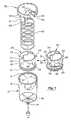
- FIG. 1is an exploded perspective view of the present infusion pump.
- FIG. 2is a vertical cross-sectional view of the assembled infusion pump.
- FIG. 3is a horizontal cross-sectional view of the infusion pump corresponding to FIG. 2 taken along lines 3 — 3 .
- FIG. 4is a detail vertical cross-sectional view corresponding to FIG. 2 taken along lines 4 — 4 showing a stop 52 extending from the cap 50 and contacting one of the steps 26 on the piston 20 .
- FIG. 5is a side elevational view of the piston 20 .
- FIG. 6is a horizontal cross-sectional view of the piston 20 corresponding to FIG. 5 taken along lines 6 — 6 .
- FIG. 7is a horizontal cross-sectional view of the piston corresponding to FIG. 5 taken along lines 7 — 7 .
- FIG. 8is a horizontal cross-sectional view of the piston corresponding to FIG. 5 taken along lines 8 — 8 .
- FIG. 9is a horizontal cross-sectional view of the piston corresponding to FIG. 5 taken along lines 9 — 9 .
- FIG. 10is a vertical cross-sectional view of a second embodiment of the infusion pump employing a piston with a series of guides on the peripheral surface of the piston guiding the stop extending from the cap along the steps on the piston in a predetermined order.
- FIG. 11is a horizontal cross-sectional view of the infusion pump corresponding to FIG. 10 taken along lines 11 — 11 .
- FIG. 12is a detailed vertical cross-sectional view corresponding to FIG. 10 taken along lines 12 — 12 , showing a stop 52 extending from the cap 50 and contacting one of the steps 26 on the piston 20 .
- FIG. 13is a side elevational view of the second embodiment of the piston 20 .
- FIG. 14is a horizontal cross-sectional view of the second embodiment of the piston 20 corresponding to FIG. 13 taken along lines 14 — 14 .
- FIG. 15is a horizontal cross-sectional view of the second embodiment of the piston 20 corresponding to FIG. 13 taken along lines 15 — 15 .
- FIG. 16is a horizontal cross-sectional view of the second embodiment of the piston 20 corresponding to FIG. 13 taken along lines 16 — 16 .
- FIG. 17is a horizontal cross-sectional view of the second embodiment of the piston 20 corresponding to FIG. 13 taken along lines 17 — 17 .
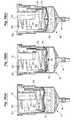
- FIGS. 18 ( a ) through 18 ( c )are three cross-sectional views of an embodiment of the present infusion pump equipped with a resilient member 70 extending across the face of the piston 20 to provide a KVO function.
- FIGS. 19 ( a ) through 19 ( c )are three cross-sectional views of another embodiment of the present infusion pump using a secondary spring 72 to assist the resilient member 70 in producing a KVO flow between doses.
- FIGS. 2 through 4are corresponding cross-sectional views of the assembled infusion pump.
- the infusion pumpincludes a pump housing 10 , which has an internal chamber 12 extending along a longitudinal axis from a proximal opening to a distal port 14 used for dispensing liquid from the chamber 12 .
- a piston 20slidably engages the internal chamber 12 of the pump housing 10 .
- An O-ring 21extending about the periphery of the piston maintains a fluid-tight seal against the wall of the pump housing 10 .
- the piston 20 and pump housing 10together define an enclosed region suitable for containing a quantity of a liquid medication or fluid.
- the chamber 12 of the pump housing 10is typically cylindrical, although other shapes could be readily substituted, provided the piston has a complementary cross-section to maintain a fluid-tight seal.
- Liquidcan be dispensed through the port 14 of the chamber 12 by sliding the piston forward along the longitudinal axis 16 , as illustrated in FIG. 2 .
- the port 14includes a duck-bill valve 15 that prevents liquid from escaping from the chamber 12 while the infusion pump is not in use.
- An infusion connectorcan be inserted through the duck-bill valve 15 , as shown in FIG. 2, to create an opening that allows liquid to flow from the chamber 12 through the connector and tubing leading to the patient.
- FIG. 5is a side elevational view of the piston 20 .
- FIGS. 6 through 9are corresponding horizontal cross-sectional views of the piston 20 at various elevations.
- the piston 20has a peripheral surface 25 above the O-ring 21 with a progression of raised steps 24 , 26 , and 28 spaced at intervals in a radial pattern on the peripheral surface 25 of the piston 20 .
- Two tabs 22extend radially outward from the peripheral surface 25 of the piston 20 to engage corresponding longitudinal slots 17 in the wall of the pump housing 10 , as depicted in FIG. 3 . These tabs 22 guide the piston 20 so that it can slide along the longitudinal axis 16 within the pump housing 10 and also prevent the piston 20 from rotating with respect to the pump housing 10 .
- a cap 50is rotatably mounted over the proximal opening of the pump housing 10 , as shown in FIG. 2 .
- the capcan be equipped with a series of tabs 56 that engage the lip 18 extending around the periphery of the proximal opening of the pump housing 10 , shown in FIGS. 2 and 4.
- the tabs 56initially clip over the lip 18 of the pump housing when the device is being assembled.
- the tabs 56 on the cap 50slide freely relative to the lip 18 on the pump housing 10 . This allows the user to easily rotate the cap 50 with respect to the pump housing 10 about the longitudinal axis 16 .
- the volume of liquid dispensedis determined by the degree of forward motion of the piston 20 . In particular, the volume dispensed is equal to the cross-sectional area of the piston multiplied by the distance that the piston moves in the axial direction.
- the flow ratecan be controlled by a flow restrictor or valve (not shown) in the tubing downstream from the infusion connector attached to the port 14 .
- the cap 50has a number of arms 51 , 53 that extend axially forward between the interior surface of the pump housing 10 and the peripheral surface 25 of the piston 20 .
- the cap 50has two diametrically-opposed arms, although any number of other configurations could be substituted.
- a stop 52 , 54extends radially inward from the distal end of each arm 51 , 53 .
- Each stopengages a selected one of the raised steps 24 , 26 , or 28 at each of a plurality of rotational positions of the cap 50 .
- the selected step 24 , 26 , or 28then limits forward axial movement of the piston 20 within the chamber 12 to dispense a predetermined quantity of liquid.
- a series of visual indicia 55 on the cap 50 and outer surface of the pump housing 10show the proper rotational positions of the cap to align the stops 52 , 54 with each of the steps 24 - 28 .
- the number of sets of steps 24 - 28 on the piston 20typically corresponds to the number of arms 51 , 53 and stops 52 , 54 extending from the cap 50 , so that each stop will engage one set of steps.
- the embodiment shown in the drawingshas two sets of steps 24 - 28 located in a diametrically-opposing arrangement on the peripheral surface 25 of the piston 20 .
- the number of steps 24 - 28 in each setis entirely a matter of design choice determined by the number and quantity of dosages that are desired.
- the present inventionenables a healthcare provider to administer medication to a patient in a series of doses over time from a single infusion pump.
- the healthcare providerdetermines which of the raised steps 24 - 28 will be engaged by the cap stops 52 , 54 as the piston 20 is pushed forward by the spring 40 . This limits the range of forward motion of the piston 20 relative to the cap 50 , and therefore determines the volume of medication to be dispensed for each rotational position of the cap 50 .
- the chamber 12 of the infusion pumpis initially loaded with medication by the manufacturer or a healthcare provider.
- the deviceis assembled with the piston 20 disposed within the pump housing 10 and the spring 40 compressed between the piston 20 and the cap 50 .
- the healthcare providerthen connects tubing with an infuser connector to the distal port 14 of the infusion pump, as illustrated in FIG. 2 .
- Pressurized fluidis fed through the tubing into the fluid chamber 12 with sufficient pressure to open the duck-bill valve 15 and overcome the force of the spring 40 .
- the tubing and infuser connectorare removed and the duck-bills of the duck-bill valve 15 return to their sealed position to retain the fluid within the pump chamber 12 .
- the liquid medicationis retained by the duck-bill valve 15 until the infusion pump is ready for use, at which time, tubing with an infuser connector is connected to the distal port 14 of the infusion pump, and the fluid is allowed to flow from the pump chamber 12 as shown in FIG. 2 .
- the devicecan be filled with a syringe or any other positive-pressure fluid source.
- the healthcare providercan select a first dosage by rotating the cap 50 so that each stop 52 , 54 is axially aligned with the first raised step 28 .
- This first dosagewill then be dispensed through the port 14 as the piston 20 moves forward from its initial, fully-retracted position until the stop 52 , 54 comes into contact with the first raised step 28 on the piston 20 . At that point, the piston 20 is restrained from further forward movement by the stop 52 , 54 and no further liquid is dispensed.
- the healthcare providercan continue with a second dosage by rotating the cap 50 so that each stop 52 , 54 is aligned with the second raised step 26 .
- the second dosageis determined by the incremental distance between the first and second steps 28 and 26 (multiplied by the cross-sectional area of the piston).
- the healthcare providercan continue with a third dosage by rotating the cap 50 so that each stop 52 , 54 is aligned with the third step 24 .
- the third dosageis determined by the incremental distance between the second and third steps 26 and 24 .
- a fourth dosagecan be selected by rotating the cap 50 so that the stop 52 , 54 is not aligned with any of the steps 24 - 28 .
- the stop 52 , 54slides along the longitudinal guide slot 31 without contacting any of the steps 24 - 26 . This allows the piston 20 to move forward until it contacts the distal wall of the chamber 12 and all of the liquid has been dispensed.
- the infusion pumpcan be initially filled with 400 ml of medication.
- the cap 50is initially turned to a first rotational position, which will cause the cap stops 52 , 54 to engage a first set of raised steps 28 after 100 ml have been dispensed.
- the capcan subsequently be rotated to a second rotational position, which will cause the cap stops 52 , 54 to engage a second set of raised steps 26 after a second 100 ml have been dispensed. If desired, this process can be repeated two more times to dispense the remaining 200 ml in two 100 ml increments.
- the infusion pumpwill be used to dispense a series of dosages in a predetermined sequence.
- the healthcare provideralso has the option of using any single step or any progression of steps.
- the healthcare providercan rotate the cap to align the stops 52 , 54 with any of the steps 24 - 28 .
- the healthcare providercan dispense a volume of medication equal to both the first and second dosages by rotating the cap to align the stops 52 , 54 directly with the second step 26 .
- FIGS. 10-17A second embodiment of the infusion pump is shown in FIGS. 10-17 having a series of guides 34 , 35 , and 36 on the peripheral surface 25 of the piston 20 forward of the raised steps 24 - 28 .
- the guides 34 - 36are intended to prevent this by guiding and limiting the path of the cap stops 52 , 54 through each of the rotational positions in proper sequence.
- FIG. 10is a vertical cross-sectional view of a second embodiment of the piston.
- FIGS. 11 and 12are corresponding horizontal and vertical cross-sectional views.
- FIG. 13is a side elevational view of the second embodiment of the piston 20 .
- FIGS. 14-17are corresponding horizontal cross-sectional views at various elevations.
- each cap stop 52 , 54is initially aligned with a longitudinal guide slot 31 (see FIGS. 10 and 13) that allows the piston 20 to be fully retracted within the piston housing 10 as liquid is loaded under pressure into the chamber 12 .
- each cap stop 52 , 54passes over an angled tab 32 in the longitudinal guide slot 31 .
- the angled tab 32allows the piston 20 to be freely retracted, but prevents the cap stop 52 , 54 from being withdrawn via the longitudinal guide slot 31 . This prevents the entire contents of the pump chamber 12 from accidentally being dispensed at one time.
- the healthcare providermust rotate the cap 50 so that the cap stop 52 , 54 slides along a circumferential guide slot 33 (defined by a circumferential guide 34 ) until the stop 52 , 54 is aligned with the first step 28 .
- the piston 20can move forward under pressure from the spring 40 until the stop 52 , 54 comes into contact with the first step 28 .
- the dosage of medication dispensedis proportional to the axial distance between the distal edge of the circumferential guide 34 and the first step 28 .
- the healthcare providercan dispense a second dose by rotating the cap 50 until the edge of the cap stop 52 , 54 contacts the shorter longitudinal guide segment 35 . This ensures that the stop 52 , 54 is in axial alignment with the second step 26 . At his point, the piston 20 moves forward once more until the stop 52 , 54 comes into contact with the second step 26 .
- the healthcare providercan dispense a third dose by the rotating the cap 50 until the edge of the cap stop 52 , 54 contacts the longer longitudinal guide segment 36 . This moves the stop 52 , 54 into axial alignment with the third step 24 . The spring 40 can then move the piston 20 forward until the stop 52 , 54 contacts the third step 24 .
- the healthcare providercan dispense the remaining liquid in the chamber 12 by rotating the cap 50 until the cap stop 52 , 54 slides past the proximal end of the longer longitudinal guide segment 36 and returns to the longitudinal guide slot 31 above the angled tab 32 . This allows the piston to move forward until the pump chamber 12 is completely emptied.
- the number of piston steps 24 - 28 and their spacing along the longitudinal axis of the piston 20can be designed to provide a variety of dose configurations.
- the number of steps 24 - 28determine the maximum number of doses that can be dispensed without reloading the infusion pump.
- a piston with one stepcan be used to dispense up to two doses.
- a piston with two stepscan be used to dispense up to three doses.
- a piston with N stepscan be used to dispense up to N+1 doses.
- the raised steps 24 - 28 and guides 34 - 36could protrude radially inward from the inside peripheral surface of the piston 20 .
- the diameter between the arms 51 , 53 extending forward from the cap 50would be slightly smaller.
- the stops 52 , 54 at the ends of the cap arms 51 , 53would point radially outward, rather than inward as shown in the figures.
- This embodimentwould have the advantage of reducing any risk that the medication might leak and come into contact with the steps 24 - 28 , guides 34 - 36 , or the components of the cap 50 that could result in contamination.
- the placement of the piston steps 24 - 28 and cap stops 52 , 54could be reversed.
- the cap 50can be equipped with a progression of inwardly-protruding steps that engage one or more stops extending outward from the peripheral surface 25 of the piston 20 .
- the raised steps 24 - 28could be replaced with grooves and/or steps that are recessed to varying degrees into the peripheral surface 25 of the piston 20 .
- the cap arms 51 , 53would slide over the peripheral surface 25 of the piston, while the stops 52 , 54 at the ends of the cap arms 51 , 53 track the recessed grooves or steps.
- FIGS. 18 ( a ) through 18 ( c )are three cross-sectional views of an embodiment of the present infusion pump equipped with a resilient member 70 extending across the face of the piston 20 to provide a KVO flow between doses.
- the infusion pumpincludes a pump housing 10 , which has an internal chamber 12 and a port 14 for dispensing liquid from the chamber 12 .
- a piston 20slidably engages the internal chamber 12 of the pump housing 10 to dispense liquid from the chamber 12 through the port 14 .
- a flow restrictor 15e.g., a duck-bill valve
- restricts the flow of liquid from the chamber 12 through the port 14thereby maintaining pressure within the chamber 12 as liquid is dispensed.
- a member 70covers at least a portion of the forward face of the piston 20 .
- the member 70can be a resilient diaphragm having a substantially convex cross-sectional shape, as depicted in FIG. 18 ( c ).
- the resilient member 70can be made of silicone, rubber, plastic, or other suitable flexible materials.
- the resilient member 70covers the entire face of the piston 20 and is secured around the periphery of the piston to define an enclosed, fluid-tight region 74 between the forward face of the piston 20 and resilient member 70 .
- the region behind the resilient member 70can be open to the atmosphere. For example, this can be accomplished by using a piston having vent openings or an incomplete piston face that allows air pressure equalization between the region behind the resilient member 70 and the region behind the piston.
- the flow restrictor 15restricts the flow from the chamber 12 and increases the pressure within the chamber 12 .
- This increased pressurecauses the resilient member 70 to move rearward from its initial position, compressing the enclosed region 74 behind the resilient member 70 .
- the air trapped in the enclosed regionacts as a spring, supplementing the resisting force provided by the resilient member 70 .
- the resilient member 70can be almost completely flattened against the face of the piston 20 as shown in FIG. 18 ( a ).
- each dosewould result from a significant movement of the piston (i.e., from one step on the piston to the next step).
- the KVO flowis provided by gradual return of the resilient member 70 to its initial position following each dose.
- FIGS. 19 ( a ) through 19 ( c )are three cross-sectional views of another embodiment of the present infusion pump using a secondary spring 72 to assist the resilient member 70 in producing a KVO flow between doses.
- the resiliency and shape of the resilient member 70serves as a kind of spring that returns the resilient member 70 to its initial form.
- the secondary spring 72provides a supplementary force to that of the resilient member 70 .
- the secondary spring 72is also compressed and exerts a resisting force as the resilient member 70 is pressed against the face of the piston 20 by the fluid pressure.
- the secondary spring 72then gradually expands to its initial state once the dose has been administered.
- the resilient member 70has a substantial degree of flexibility and elasticity in the preferred embodiment of the present invention, primarily for reasons of simplicity and cost.
- a substantially rigid member or face plate backed by a secondary spring 72could be substituted in FIGS. 19 ( a )- 19 ( c ).
- the periphery of the rigid membercan be sealed to the piston by means of a flexible skirt or a bellows arrangement to maintain a fluid tight region behind the rigid member.
Landscapes
- Health & Medical Sciences (AREA)
- Heart & Thoracic Surgery (AREA)
- Hematology (AREA)
- Anesthesiology (AREA)
- Biomedical Technology (AREA)
- Engineering & Computer Science (AREA)
- Life Sciences & Earth Sciences (AREA)
- Animal Behavior & Ethology (AREA)
- General Health & Medical Sciences (AREA)
- Public Health (AREA)
- Veterinary Medicine (AREA)
- Vascular Medicine (AREA)
- Pulmonology (AREA)
- Infusion, Injection, And Reservoir Apparatuses (AREA)
Abstract
Description
| Inventor | Patent No. | Issue Date | ||
| Drypen et al. | 5,318,544 | June 7, 1994 | ||
| Ishikawa | 5,178,609 | Jan. 12, 1993 | ||
| Zdeb | 5,135,500 | Aug. 4, 1992 | ||
| Wender et al. | 5,024,661 | June 18, 1991 | ||
| LeFevre | 4,997,420 | March 5, 1991 | ||
| Chang | 4,991,742 | Feb. 12, 1991 | ||
| Gangemi | 4,966,585 | Oct. 30, 1990 | ||
| Borchard | 4,962,868 | Oct. 16, 1990 | ||
| Raphael et al. | 4,832,694 | May 23, 1989 | ||
| Vaillancourt | 4,813,937 | Mar. 21, 1989 | ||
| France | 2,561,925 | Oct. 4, 1985 |
| Oshikubo | 4,467,942 | Aug. 28, 1984 | |
| Sanchez | 4,050,459 | Sep. 27, 1977 | |
| Bull et al. | 3,492,876 | Feb. 3, 1970 |
| France | 1,156,298 | May 14, 1958 |
| Kapelsohn | 2,792,834 | May 21, 1957 | ||
| Mathis | 2,428,577 | Oct. 7, 1947 | ||
| Inventor | Patent No. | Issue Date | ||
| Racz | 5,722,955 | March 3, 1998 | ||
| Webb | 4,333,456 | June 8, 1982 | ||
| Binard et al. | 4,240,430 | Dec. 23, 1980 | ||
| Binard et al. | 4,074,714 | Feb. 21, 1978 | ||
| Leibinsohn | 4,064,879 | Dec. 27, 1977 | ||
| Binard et al. | 4,030,497 | June 21, 1977 | ||
| Binard et al. | 4,000,741 | Jan. 4, 1977 | ||
| Dawe | 3,998,223 | Dec. 21, 1976 | ||
Claims (18)
Priority Applications (4)
| Application Number | Priority Date | Filing Date | Title |
|---|---|---|---|
| US09/598,644US6348043B1 (en) | 1998-12-29 | 2000-06-21 | Multi-dose infusion pump providing minimal flow between doses |
| PCT/US2001/019776WO2001097876A1 (en) | 2000-06-21 | 2001-06-21 | Multi-dose infusion pump providing minimal flow between doses |
| AU2001271362AAU2001271362A1 (en) | 2000-06-21 | 2001-06-21 | Multi-dose infusion pump providing minimal flow between doses |
| EP01950363AEP1499371B1 (en) | 2000-06-21 | 2001-06-21 | Multi-dose infusion pump providing minimal flow between doses |
Applications Claiming Priority (3)
| Application Number | Priority Date | Filing Date | Title |
|---|---|---|---|
| US11420698P | 1998-12-29 | 1998-12-29 | |
| US09/226,482US6083201A (en) | 1999-01-07 | 1999-01-07 | Multi-dose infusion pump |
| US09/598,644US6348043B1 (en) | 1998-12-29 | 2000-06-21 | Multi-dose infusion pump providing minimal flow between doses |
Related Parent Applications (1)
| Application Number | Title | Priority Date | Filing Date |
|---|---|---|---|
| US09/226,482Continuation-In-PartUS6083201A (en) | 1998-12-29 | 1999-01-07 | Multi-dose infusion pump |
Publications (1)
| Publication Number | Publication Date |
|---|---|
| US6348043B1true US6348043B1 (en) | 2002-02-19 |
Family
ID=24396376
Family Applications (1)
| Application Number | Title | Priority Date | Filing Date |
|---|---|---|---|
| US09/598,644Expired - LifetimeUS6348043B1 (en) | 1998-12-29 | 2000-06-21 | Multi-dose infusion pump providing minimal flow between doses |
Country Status (4)
| Country | Link |
|---|---|
| US (1) | US6348043B1 (en) |
| EP (1) | EP1499371B1 (en) |
| AU (1) | AU2001271362A1 (en) |
| WO (1) | WO2001097876A1 (en) |
Cited By (28)
| Publication number | Priority date | Publication date | Assignee | Title |
|---|---|---|---|---|
| US20030158523A1 (en)* | 1999-04-16 | 2003-08-21 | Birger Hjertman | Injector device and method for its operation |
| WO2004009162A1 (en) | 2002-07-24 | 2004-01-29 | Disetronic Licensing Ag | Infusion pump, method, control program and semiconductor means for the dosed administration of a medicinal liquid |
| US20050159708A1 (en)* | 2002-07-24 | 2005-07-21 | Rudolf Sidler | Infusion pump, control program, semiconductor means and method for the dosed administration of a medicinal liquid |
| US20050187532A1 (en)* | 2004-02-24 | 2005-08-25 | Medex, Inc. | Diaphragm-based reservoir for a closed blood sampling system |
| US20070078380A1 (en)* | 2002-08-12 | 2007-04-05 | Marc Yap | System and method for tension-activated fluid control |
| CN100398163C (en)* | 2004-11-24 | 2008-07-02 | 周冠旻 | Medical low infusion set |
| WO2008059385A3 (en)* | 2006-11-16 | 2008-09-12 | Becton Dickinson France | Device for automatic delivery of successive doses of product |
| US20090088724A1 (en)* | 2007-09-27 | 2009-04-02 | Tyco Healthcare Group Lp | Multiple Stage Fluid Delivery Device and Method of Use |
| US20090157005A1 (en)* | 2003-04-23 | 2009-06-18 | Gonnelli Robert R | Hydraulically actuated pump for long duration medicament administration |
| US20090326475A1 (en)* | 2008-06-30 | 2009-12-31 | Tyco Healthcare Group Lp | Syringe Assembly with Plunger Having a Secondary Dispensing Reservoir |
| US20100106082A1 (en)* | 2008-10-24 | 2010-04-29 | Baxter International Inc. | In situ tubing measurements for infusion pumps |
| WO2010112377A1 (en)* | 2009-03-31 | 2010-10-07 | Sanofi-Aventis Deutschland Gmbh | Improvements in and relating to a medicament delivery devices |
| US7914499B2 (en) | 2006-03-30 | 2011-03-29 | Valeritas, Inc. | Multi-cartridge fluid delivery device |
| WO2011039211A1 (en)* | 2009-09-30 | 2011-04-07 | Sanofi-Aventis Deutschland Gmbh | Button member for operating a drive assembly |
| US20110158823A1 (en)* | 2009-12-31 | 2011-06-30 | Baxter International Inc. | Shuttle pump with controlled geometry |
| US8137083B2 (en) | 2009-03-11 | 2012-03-20 | Baxter International Inc. | Infusion pump actuators, system and method for controlling medical fluid flowrate |
| US20120110960A1 (en)* | 2009-05-27 | 2012-05-10 | Sartorius Stedim Biotech S.A. | Rigid container for a flexible pouch for holding a biopharmaceutical fluid, assembly comprising such a flexible pouch and such a container, and method for using such a container |
| US8567235B2 (en) | 2010-06-29 | 2013-10-29 | Baxter International Inc. | Tube measurement technique using linear actuator and pressure sensor |
| US8673823B2 (en) | 2010-03-18 | 2014-03-18 | Sanofi | Methods and uses relating to the identification of compound involved in pain as well as methods of diagnosing algesia |
| US20150100027A1 (en)* | 2008-08-05 | 2015-04-09 | Antares Pharma, Inc. | Multiple dosage injector |
| US9089636B2 (en) | 2004-07-02 | 2015-07-28 | Valeritas, Inc. | Methods and devices for delivering GLP-1 and uses thereof |
| US20150209570A1 (en)* | 2014-01-24 | 2015-07-30 | Freddie Eng Hwee Lee | Compression element driven fluid delivery apparatus |
| JP2017505203A (en)* | 2014-02-12 | 2017-02-16 | ニュー インジェクション システムズ リミテッド | Syringe assembly |
| US20170143912A1 (en)* | 2014-10-29 | 2017-05-25 | Promised Hangzhou Meditech Co.,Ltd. | Safety pen needle |
| US9839746B2 (en) | 2014-01-24 | 2017-12-12 | Freddie Eng Hwee Lee | Elastic band powered fluid delivery apparatus |
| WO2018031867A1 (en)* | 2016-08-11 | 2018-02-15 | Patrick Kenneth Powell | Vacuum pump |
| US10960132B1 (en)* | 2017-01-31 | 2021-03-30 | Verily Life Sciences Llc | Clutched delivery device |
| US11607490B2 (en)* | 2016-11-01 | 2023-03-21 | Sanofi-Aventis Deutschland Gmbh | Volume measuring arrangement |
Families Citing this family (4)
| Publication number | Priority date | Publication date | Assignee | Title |
|---|---|---|---|---|
| CN102151343B (en)* | 2011-04-30 | 2012-12-12 | 中国人民解放军第三军医大学第三附属医院 | Portable infusion set |
| EP3159029B1 (en)* | 2015-10-20 | 2021-12-15 | Ace Medical Co., Ltd | Liquid injector for continuously injecting fixed quantity of charged liquid |
| EP3787715B1 (en)* | 2018-05-02 | 2023-11-08 | Cequr SA | Devices and methods for providing a bolus dose in a microfluidic circuit of a pump |
| CN115254224B (en)* | 2022-07-29 | 2024-03-19 | 广州国睿科学仪器有限公司 | Extraction assembly for bottle mouth pipettor |
Citations (52)
| Publication number | Priority date | Publication date | Assignee | Title |
|---|---|---|---|---|
| US1123990A (en) | 1914-08-12 | 1915-01-05 | Harry L Calhoun | Syringe. |
| US1476946A (en) | 1922-03-20 | 1923-12-11 | Alfred N Bessesen | Fluid-pressure device |
| US2428577A (en) | 1945-09-06 | 1947-10-07 | Waddy T Mathis | Liquid-measuring dispenser |
| US2605765A (en) | 1947-06-05 | 1952-08-05 | Kollsman Paul | Automatic syringe |
| US2792834A (en) | 1955-09-22 | 1957-05-21 | Scientific Industries | Operating device for syringe or pipet |
| FR1156298A (en) | 1956-09-06 | 1958-05-14 | Seringues Ind Soc D Expl Des | Syringe for hypodermic injections |
| US3492876A (en) | 1968-02-08 | 1970-02-03 | Us Health Education & Welfare | Aliquant discharge device |
| US3565292A (en) | 1969-03-03 | 1971-02-23 | Walter J Jinotti | Blood-profusing apparatus |
| US3863624A (en) | 1973-06-15 | 1975-02-04 | Hans Gram | Vacuum curettage device |
| US3874382A (en)* | 1972-04-04 | 1975-04-01 | Louis Nogier | Sealing piston cap for hypodermic injection syringe |
| US4036232A (en) | 1976-04-19 | 1977-07-19 | Abbott Laboratories | Aspiration device |
| US4050459A (en) | 1975-05-23 | 1977-09-27 | Anacleto Montero Sanchez | Hypodermic syringe |
| US4180067A (en) | 1976-09-28 | 1979-12-25 | Pye (Electronic Products) Limited | Apparatus for delivering fluids with controlled rates of flow |
| US4312347A (en) | 1980-02-25 | 1982-01-26 | Iowa State University Research Foundation, Inc. | Positive pressure drug releasing device |
| US4381006A (en) | 1980-11-10 | 1983-04-26 | Abbott Laboratories | Continuous low flow rate fluid dispenser |
| US4456152A (en) | 1982-05-03 | 1984-06-26 | Young Don H | Measuring and dispensing apparatus |
| US4467942A (en) | 1982-04-29 | 1984-08-28 | Yuuji Oshikubo | Repeating dispenser |
| FR2561925A3 (en) | 1984-03-30 | 1985-10-04 | Novo Industri As | Disposable device for injecting predetermined and successive quantities of a medicine |
| US4561856A (en) | 1983-08-18 | 1985-12-31 | Cochran Ulrich D | Infusion pump |
| US4666430A (en) | 1984-12-05 | 1987-05-19 | I-Flow Corporation | Infusion pump |
| US4676256A (en) | 1986-03-24 | 1987-06-30 | Golden Theodore A | Hypodermic device |
| US4765509A (en) | 1986-10-02 | 1988-08-23 | Adhesive Engineering Company | Pumping system |
| US4773900A (en) | 1986-08-20 | 1988-09-27 | Cochran Ulrich D | Infusion device |
| US4813937A (en) | 1986-05-07 | 1989-03-21 | Vaillancourt Vincent L | Ambulatory disposable infusion delivery system |
| US4832694A (en) | 1988-02-08 | 1989-05-23 | Raphael Iii Julian J | Programmed action hypodermic syringe |
| US4874386A (en) | 1986-12-05 | 1989-10-17 | Sta-Set Corporation | Fluid dispensing device |
| US4962868A (en) | 1988-03-25 | 1990-10-16 | Henning Berlin Gmbh | Apparatus for dispensing a controlled dose of a liquid fluid |
| US4966585A (en) | 1988-05-31 | 1990-10-30 | Gangemi Ronald J | Infusion apparatus |
| US4991742A (en) | 1989-08-01 | 1991-02-12 | Chang Chin Fu | Automatic drip bottle set |
| US4997420A (en) | 1989-12-28 | 1991-03-05 | Lefevre Robert J | Portable drug delivery device including pump with tapered barrel |
| WO1991006338A1 (en) | 1989-10-31 | 1991-05-16 | Prime Medical Products, Inc. | Self-driven pump device |
| WO1991008002A1 (en) | 1989-12-05 | 1991-06-13 | Prime Medical Products, Inc. | Self-driven pump device |
| US5024661A (en) | 1989-08-16 | 1991-06-18 | Empire Research Corporation | Non-reuseable hypodermic syringe |
| US5059174A (en) | 1990-08-23 | 1991-10-22 | Vaillancourt Vincent L | Fluid infusion delivery system |
| WO1991016093A1 (en) | 1990-04-26 | 1991-10-31 | Baxter International Inc. | Vaccum infusion device |
| US5062834A (en) | 1989-02-24 | 1991-11-05 | Product Development (S.G.Z.) Ltd | Device for dispensing a liquid particularly useful for delivering medicaments at a predetermined rate |
| US5078679A (en) | 1990-11-13 | 1992-01-07 | Reese H William | Post-surgical anesthesia at a continuous and progressively decreasing administration rate |
| US5098385A (en) | 1990-04-26 | 1992-03-24 | Baxter International Inc. | Two-way valve for infusion devices |
| US5100389A (en) | 1988-06-21 | 1992-03-31 | Vaillancourt Vincent L | Ambulatory infusion pump |
| US5178610A (en)* | 1990-07-05 | 1993-01-12 | Nissho Corporation | Liquid infusion device |
| US5178609A (en) | 1990-06-19 | 1993-01-12 | Kato Hatsujo Kaisha, Ltd. | Medical liquid injector for continuous transfusion |
| US5290259A (en) | 1993-02-18 | 1994-03-01 | Ultradent Products, Inc. | Double syringe delivery system |
| US5318544A (en) | 1992-10-20 | 1994-06-07 | Kerr Manufacturing Company | Metering syringe |
| US5346476A (en) | 1992-04-29 | 1994-09-13 | Edward E. Elson | Fluid delivery system |
| US5360411A (en) | 1992-10-12 | 1994-11-01 | Opto Tech Co., Ltd. | Liquid medicine injecting device |
| US5411485A (en) | 1993-04-19 | 1995-05-02 | Hyprotek | Catheter access system and method |
| US5454792A (en) | 1993-04-19 | 1995-10-03 | Hyproteck, Inc. | Linear slide valve for CVC access |
| USRE35192E (en) | 1990-11-13 | 1996-03-26 | Phoenix Surgical Products, Inc. | Post-surgical anesthesia at a continuous and progressively decreasing administration rate |
| US5599315A (en) | 1995-12-01 | 1997-02-04 | Charles J. McPhee | Syringe actuation device |
| US5620423A (en)* | 1993-09-23 | 1997-04-15 | Heraeus Kulzer Gmbh | Syringe for the controlled discharge of viscous materials |
| US5735825A (en)* | 1996-03-22 | 1998-04-07 | Merit Medical Systems, Inc. | Syringe plunger tip |
| US5897530A (en)* | 1997-12-24 | 1999-04-27 | Baxter International Inc. | Enclosed ambulatory pump |
Family Cites Families (3)
| Publication number | Priority date | Publication date | Assignee | Title |
|---|---|---|---|---|
| US5462256A (en)* | 1994-05-13 | 1995-10-31 | Abbott Laboratories | Push button flow stop useable with a disposable infusion pumping chamber cassette |
| JP3928248B2 (en) | 1998-02-27 | 2007-06-13 | ニプロ株式会社 | Chemical liquid self-injection tool |
| US5906597A (en)* | 1998-06-09 | 1999-05-25 | I-Flow Corporation | Patient-controlled drug administration device |
- 2000
- 2000-06-21USUS09/598,644patent/US6348043B1/ennot_activeExpired - Lifetime
- 2001
- 2001-06-21EPEP01950363Apatent/EP1499371B1/ennot_activeExpired - Lifetime
- 2001-06-21WOPCT/US2001/019776patent/WO2001097876A1/enactiveApplication Filing
- 2001-06-21AUAU2001271362Apatent/AU2001271362A1/ennot_activeAbandoned
Patent Citations (53)
| Publication number | Priority date | Publication date | Assignee | Title |
|---|---|---|---|---|
| US1123990A (en) | 1914-08-12 | 1915-01-05 | Harry L Calhoun | Syringe. |
| US1476946A (en) | 1922-03-20 | 1923-12-11 | Alfred N Bessesen | Fluid-pressure device |
| US2428577A (en) | 1945-09-06 | 1947-10-07 | Waddy T Mathis | Liquid-measuring dispenser |
| US2605765A (en) | 1947-06-05 | 1952-08-05 | Kollsman Paul | Automatic syringe |
| US2792834A (en) | 1955-09-22 | 1957-05-21 | Scientific Industries | Operating device for syringe or pipet |
| FR1156298A (en) | 1956-09-06 | 1958-05-14 | Seringues Ind Soc D Expl Des | Syringe for hypodermic injections |
| US3492876A (en) | 1968-02-08 | 1970-02-03 | Us Health Education & Welfare | Aliquant discharge device |
| US3565292A (en) | 1969-03-03 | 1971-02-23 | Walter J Jinotti | Blood-profusing apparatus |
| US3874382A (en)* | 1972-04-04 | 1975-04-01 | Louis Nogier | Sealing piston cap for hypodermic injection syringe |
| US3863624A (en) | 1973-06-15 | 1975-02-04 | Hans Gram | Vacuum curettage device |
| US4050459A (en) | 1975-05-23 | 1977-09-27 | Anacleto Montero Sanchez | Hypodermic syringe |
| US4036232A (en) | 1976-04-19 | 1977-07-19 | Abbott Laboratories | Aspiration device |
| US4180067A (en) | 1976-09-28 | 1979-12-25 | Pye (Electronic Products) Limited | Apparatus for delivering fluids with controlled rates of flow |
| US4312347A (en) | 1980-02-25 | 1982-01-26 | Iowa State University Research Foundation, Inc. | Positive pressure drug releasing device |
| US4381006A (en) | 1980-11-10 | 1983-04-26 | Abbott Laboratories | Continuous low flow rate fluid dispenser |
| US4467942A (en) | 1982-04-29 | 1984-08-28 | Yuuji Oshikubo | Repeating dispenser |
| US4456152A (en) | 1982-05-03 | 1984-06-26 | Young Don H | Measuring and dispensing apparatus |
| US4561856A (en) | 1983-08-18 | 1985-12-31 | Cochran Ulrich D | Infusion pump |
| FR2561925A3 (en) | 1984-03-30 | 1985-10-04 | Novo Industri As | Disposable device for injecting predetermined and successive quantities of a medicine |
| US4666430A (en) | 1984-12-05 | 1987-05-19 | I-Flow Corporation | Infusion pump |
| US4676256A (en) | 1986-03-24 | 1987-06-30 | Golden Theodore A | Hypodermic device |
| US4813937A (en) | 1986-05-07 | 1989-03-21 | Vaillancourt Vincent L | Ambulatory disposable infusion delivery system |
| US4773900A (en) | 1986-08-20 | 1988-09-27 | Cochran Ulrich D | Infusion device |
| US4765509A (en) | 1986-10-02 | 1988-08-23 | Adhesive Engineering Company | Pumping system |
| US4874386A (en) | 1986-12-05 | 1989-10-17 | Sta-Set Corporation | Fluid dispensing device |
| US4832694A (en) | 1988-02-08 | 1989-05-23 | Raphael Iii Julian J | Programmed action hypodermic syringe |
| US4962868A (en) | 1988-03-25 | 1990-10-16 | Henning Berlin Gmbh | Apparatus for dispensing a controlled dose of a liquid fluid |
| US4966585A (en) | 1988-05-31 | 1990-10-30 | Gangemi Ronald J | Infusion apparatus |
| US5100389A (en) | 1988-06-21 | 1992-03-31 | Vaillancourt Vincent L | Ambulatory infusion pump |
| US5062834A (en) | 1989-02-24 | 1991-11-05 | Product Development (S.G.Z.) Ltd | Device for dispensing a liquid particularly useful for delivering medicaments at a predetermined rate |
| US4991742A (en) | 1989-08-01 | 1991-02-12 | Chang Chin Fu | Automatic drip bottle set |
| US5024661A (en) | 1989-08-16 | 1991-06-18 | Empire Research Corporation | Non-reuseable hypodermic syringe |
| WO1991006338A1 (en) | 1989-10-31 | 1991-05-16 | Prime Medical Products, Inc. | Self-driven pump device |
| US5135500A (en) | 1989-10-31 | 1992-08-04 | Prime Medical Products, Inc. | Self-driven pump device |
| WO1991008002A1 (en) | 1989-12-05 | 1991-06-13 | Prime Medical Products, Inc. | Self-driven pump device |
| US4997420A (en) | 1989-12-28 | 1991-03-05 | Lefevre Robert J | Portable drug delivery device including pump with tapered barrel |
| WO1991016093A1 (en) | 1990-04-26 | 1991-10-31 | Baxter International Inc. | Vaccum infusion device |
| US5098385A (en) | 1990-04-26 | 1992-03-24 | Baxter International Inc. | Two-way valve for infusion devices |
| US5178609A (en) | 1990-06-19 | 1993-01-12 | Kato Hatsujo Kaisha, Ltd. | Medical liquid injector for continuous transfusion |
| US5178610A (en)* | 1990-07-05 | 1993-01-12 | Nissho Corporation | Liquid infusion device |
| US5059174A (en) | 1990-08-23 | 1991-10-22 | Vaillancourt Vincent L | Fluid infusion delivery system |
| US5078679A (en) | 1990-11-13 | 1992-01-07 | Reese H William | Post-surgical anesthesia at a continuous and progressively decreasing administration rate |
| USRE35192E (en) | 1990-11-13 | 1996-03-26 | Phoenix Surgical Products, Inc. | Post-surgical anesthesia at a continuous and progressively decreasing administration rate |
| US5346476A (en) | 1992-04-29 | 1994-09-13 | Edward E. Elson | Fluid delivery system |
| US5360411A (en) | 1992-10-12 | 1994-11-01 | Opto Tech Co., Ltd. | Liquid medicine injecting device |
| US5318544A (en) | 1992-10-20 | 1994-06-07 | Kerr Manufacturing Company | Metering syringe |
| US5290259A (en) | 1993-02-18 | 1994-03-01 | Ultradent Products, Inc. | Double syringe delivery system |
| US5411485A (en) | 1993-04-19 | 1995-05-02 | Hyprotek | Catheter access system and method |
| US5454792A (en) | 1993-04-19 | 1995-10-03 | Hyproteck, Inc. | Linear slide valve for CVC access |
| US5620423A (en)* | 1993-09-23 | 1997-04-15 | Heraeus Kulzer Gmbh | Syringe for the controlled discharge of viscous materials |
| US5599315A (en) | 1995-12-01 | 1997-02-04 | Charles J. McPhee | Syringe actuation device |
| US5735825A (en)* | 1996-03-22 | 1998-04-07 | Merit Medical Systems, Inc. | Syringe plunger tip |
| US5897530A (en)* | 1997-12-24 | 1999-04-27 | Baxter International Inc. | Enclosed ambulatory pump |
Cited By (65)
| Publication number | Priority date | Publication date | Assignee | Title |
|---|---|---|---|---|
| US20030158523A1 (en)* | 1999-04-16 | 2003-08-21 | Birger Hjertman | Injector device and method for its operation |
| US7396347B2 (en)* | 1999-04-16 | 2008-07-08 | Pfizer Health Ab | Injector device and method for its operation |
| WO2004009162A1 (en) | 2002-07-24 | 2004-01-29 | Disetronic Licensing Ag | Infusion pump, method, control program and semiconductor means for the dosed administration of a medicinal liquid |
| DE10233622A1 (en)* | 2002-07-24 | 2004-02-12 | Disetronic Licensing Ag | Infusion pump, method, control program and semiconductor component for the metered administration of a medical liquid |
| US20050159708A1 (en)* | 2002-07-24 | 2005-07-21 | Rudolf Sidler | Infusion pump, control program, semiconductor means and method for the dosed administration of a medicinal liquid |
| US20050182391A1 (en)* | 2002-07-24 | 2005-08-18 | Gilbert Schiltges | Administering device with an osmotic drive |
| EP2484392A1 (en) | 2002-07-24 | 2012-08-08 | F. Hoffmann-La Roche AG | Infusion pump for the dosed administration of a medicinal liquid |
| US7419484B2 (en) | 2002-07-24 | 2008-09-02 | Disetronic Licensing Ag | Administering device with an osmotic drive |
| US7520871B2 (en) | 2002-08-12 | 2009-04-21 | Lma North America, Inc | System and method for tension-activated fluid control |
| US20070078380A1 (en)* | 2002-08-12 | 2007-04-05 | Marc Yap | System and method for tension-activated fluid control |
| US20090182265A1 (en)* | 2002-08-12 | 2009-07-16 | Lma North America, Inc | Medication infusion system and method |
| US7527608B2 (en) | 2002-08-12 | 2009-05-05 | Lma North America, Inc. | Medication infusion and aspiration system and method |
| US20100217191A1 (en)* | 2003-04-23 | 2010-08-26 | Valeritas, Inc. | Hydraulically actuated pump for fluid administration |
| US10525194B2 (en) | 2003-04-23 | 2020-01-07 | Valeritas, Inc. | Hydraulically actuated pump for fluid administration |
| US20090157005A1 (en)* | 2003-04-23 | 2009-06-18 | Gonnelli Robert R | Hydraulically actuated pump for long duration medicament administration |
| US9072828B2 (en)* | 2003-04-23 | 2015-07-07 | Valeritas, Inc. | Hydraulically actuated pump for long duration medicament administration |
| US9511187B2 (en) | 2003-04-23 | 2016-12-06 | Valeritas, Inc. | Hydraulically actuated pump for fluid administration |
| US11642456B2 (en) | 2003-04-23 | 2023-05-09 | Mannkind Corporation | Hydraulically actuated pump for fluid administration |
| US9125983B2 (en)* | 2003-04-23 | 2015-09-08 | Valeritas, Inc. | Hydraulically actuated pump for fluid administration |
| US8070726B2 (en) | 2003-04-23 | 2011-12-06 | Valeritas, Inc. | Hydraulically actuated pump for long duration medicament administration |
| US20050187532A1 (en)* | 2004-02-24 | 2005-08-25 | Medex, Inc. | Diaphragm-based reservoir for a closed blood sampling system |
| US9089636B2 (en) | 2004-07-02 | 2015-07-28 | Valeritas, Inc. | Methods and devices for delivering GLP-1 and uses thereof |
| US20090182307A1 (en)* | 2004-07-30 | 2009-07-16 | Lma North America, Inc. | System and Method for Tension-Activated Fluid Control |
| CN100398163C (en)* | 2004-11-24 | 2008-07-02 | 周冠旻 | Medical low infusion set |
| US12246159B2 (en) | 2006-03-30 | 2025-03-11 | Mannkind Corporation | Multi-cartridge fluid delivery device |
| US8821443B2 (en) | 2006-03-30 | 2014-09-02 | Valeritas, Inc. | Multi-cartridge fluid delivery device |
| US10493199B2 (en) | 2006-03-30 | 2019-12-03 | Valeritas, Inc. | Multi-cartridge fluid delivery device |
| US7914499B2 (en) | 2006-03-30 | 2011-03-29 | Valeritas, Inc. | Multi-cartridge fluid delivery device |
| US9687599B2 (en) | 2006-03-30 | 2017-06-27 | Valeritas, Inc. | Multi-cartridge fluid delivery device |
| US8361053B2 (en) | 2006-03-30 | 2013-01-29 | Valeritas, Inc. | Multi-cartridge fluid delivery device |
| US20100145275A1 (en)* | 2006-11-16 | 2010-06-10 | Becton Dickinson France S.A.S. | Device for Automatic Delivery of Successive Doses of Product |
| US8568358B2 (en)* | 2006-11-16 | 2013-10-29 | Becton Dickinson France | Device for automatic delivery of successive doses of product |
| WO2008059385A3 (en)* | 2006-11-16 | 2008-09-12 | Becton Dickinson France | Device for automatic delivery of successive doses of product |
| US20090088724A1 (en)* | 2007-09-27 | 2009-04-02 | Tyco Healthcare Group Lp | Multiple Stage Fluid Delivery Device and Method of Use |
| US8506527B2 (en) | 2008-06-30 | 2013-08-13 | Covidien Lp | Syringe assembly with plunger having a secondary dispensing reservoir |
| US8142403B2 (en) | 2008-06-30 | 2012-03-27 | Tyco Healthcare Group Lp | Syringe assembly with plunger having a secondary dispensing reservoir |
| US20090326475A1 (en)* | 2008-06-30 | 2009-12-31 | Tyco Healthcare Group Lp | Syringe Assembly with Plunger Having a Secondary Dispensing Reservoir |
| US9561333B2 (en)* | 2008-08-05 | 2017-02-07 | Antares Pharma, Inc. | Multiple dosage injector |
| US10300212B2 (en) | 2008-08-05 | 2019-05-28 | Antares Pharma, Inc. | Multiple dosage injector |
| US11058824B2 (en)* | 2008-08-05 | 2021-07-13 | Antares Pharma, Inc. | Multiple dosage injector |
| US20150100027A1 (en)* | 2008-08-05 | 2015-04-09 | Antares Pharma, Inc. | Multiple dosage injector |
| US8496613B2 (en) | 2008-10-24 | 2013-07-30 | Baxter International Inc. | In situ tubing measurements for infusion pumps |
| US20100106082A1 (en)* | 2008-10-24 | 2010-04-29 | Baxter International Inc. | In situ tubing measurements for infusion pumps |
| US8105269B2 (en) | 2008-10-24 | 2012-01-31 | Baxter International Inc. | In situ tubing measurements for infusion pumps |
| US8137083B2 (en) | 2009-03-11 | 2012-03-20 | Baxter International Inc. | Infusion pump actuators, system and method for controlling medical fluid flowrate |
| WO2010112377A1 (en)* | 2009-03-31 | 2010-10-07 | Sanofi-Aventis Deutschland Gmbh | Improvements in and relating to a medicament delivery devices |
| US9266657B2 (en)* | 2009-05-27 | 2016-02-23 | Sartorius Stedim Fmt Sas | Rigid container for a flexible pouch for holding a biopharmaceutical fluid, assembly comprising such a flexible pouch and such a container, and method for using such a container |
| US10618716B2 (en) | 2009-05-27 | 2020-04-14 | Sartorius Stedim Fmt Sas | Rigid container for a flexible pouch for holding a biopharmaceutical fluid, assembly comprising such a flexible pouch and such a container, and method for using such a container |
| US20120110960A1 (en)* | 2009-05-27 | 2012-05-10 | Sartorius Stedim Biotech S.A. | Rigid container for a flexible pouch for holding a biopharmaceutical fluid, assembly comprising such a flexible pouch and such a container, and method for using such a container |
| WO2011039211A1 (en)* | 2009-09-30 | 2011-04-07 | Sanofi-Aventis Deutschland Gmbh | Button member for operating a drive assembly |
| US8382447B2 (en) | 2009-12-31 | 2013-02-26 | Baxter International, Inc. | Shuttle pump with controlled geometry |
| US20110158823A1 (en)* | 2009-12-31 | 2011-06-30 | Baxter International Inc. | Shuttle pump with controlled geometry |
| US8673823B2 (en) | 2010-03-18 | 2014-03-18 | Sanofi | Methods and uses relating to the identification of compound involved in pain as well as methods of diagnosing algesia |
| US8567235B2 (en) | 2010-06-29 | 2013-10-29 | Baxter International Inc. | Tube measurement technique using linear actuator and pressure sensor |
| US9839746B2 (en) | 2014-01-24 | 2017-12-12 | Freddie Eng Hwee Lee | Elastic band powered fluid delivery apparatus |
| US9833568B2 (en)* | 2014-01-24 | 2017-12-05 | Freddie Eng Hwee Lee | Compression element driven fluid delivery apparatus |
| US20150209570A1 (en)* | 2014-01-24 | 2015-07-30 | Freddie Eng Hwee Lee | Compression element driven fluid delivery apparatus |
| JP2017505203A (en)* | 2014-02-12 | 2017-02-16 | ニュー インジェクション システムズ リミテッド | Syringe assembly |
| US10022505B2 (en)* | 2014-10-29 | 2018-07-17 | Promisemed Hangzhou Meditech Co., Ltd. | Safety pen needle |
| US20170143912A1 (en)* | 2014-10-29 | 2017-05-25 | Promised Hangzhou Meditech Co.,Ltd. | Safety pen needle |
| US11236742B2 (en) | 2016-08-11 | 2022-02-01 | Stakpac, Llc | Vacuum pump |
| WO2018031867A1 (en)* | 2016-08-11 | 2018-02-15 | Patrick Kenneth Powell | Vacuum pump |
| US11767839B2 (en) | 2016-08-11 | 2023-09-26 | Ag Ip Holding, Llc | Vacuum pump |
| US11607490B2 (en)* | 2016-11-01 | 2023-03-21 | Sanofi-Aventis Deutschland Gmbh | Volume measuring arrangement |
| US10960132B1 (en)* | 2017-01-31 | 2021-03-30 | Verily Life Sciences Llc | Clutched delivery device |
Also Published As
| Publication number | Publication date |
|---|---|
| EP1499371B1 (en) | 2012-08-08 |
| EP1499371A1 (en) | 2005-01-26 |
| WO2001097876A1 (en) | 2001-12-27 |
| EP1499371A4 (en) | 2008-07-09 |
| AU2001271362A1 (en) | 2002-01-02 |
Similar Documents
| Publication | Publication Date | Title |
|---|---|---|
| US6348043B1 (en) | Multi-dose infusion pump providing minimal flow between doses | |
| US6083201A (en) | Multi-dose infusion pump | |
| US11324883B2 (en) | Ambulatory infusion system initialization | |
| US8394061B2 (en) | Drug delivery apparatus | |
| US5304165A (en) | Syringe-filling medication dispenser | |
| US5300041A (en) | Dose setting and repeating syringe | |
| US4381006A (en) | Continuous low flow rate fluid dispenser | |
| US4561856A (en) | Infusion pump | |
| EP1146922A1 (en) | Spring-powered infusion pump | |
| RU2134592C1 (en) | Device for controlled feed of liquids | |
| AU2018334143B2 (en) | Sliding syringe cap for separate filling and delivery | |
| EP3258995B1 (en) | Syringe systems, piston seal systems, stopper systems, and methods of use and assembly | |
| JPH05253295A (en) | Discharge injector with precision | |
| US9833568B2 (en) | Compression element driven fluid delivery apparatus | |
| US20210290842A1 (en) | Pump | |
| CN117279680A (en) | Component and subassembly for a medicament delivery device |
Legal Events
| Date | Code | Title | Description |
|---|---|---|---|
| AS | Assignment | Owner name:MCKINLEY MEDICAL, LLP, COLORADO Free format text:ASSIGNMENT OF ASSIGNORS INTEREST;ASSIGNORS:HAGEN, JEFFREY A.;SKINKLE, DAVID W.;REEL/FRAME:010897/0082;SIGNING DATES FROM 20000606 TO 20000613 | |
| FEPP | Fee payment procedure | Free format text:PAYOR NUMBER ASSIGNED (ORIGINAL EVENT CODE: ASPN); ENTITY STATUS OF PATENT OWNER: LARGE ENTITY | |
| STCF | Information on status: patent grant | Free format text:PATENTED CASE | |
| FPAY | Fee payment | Year of fee payment:4 | |
| AS | Assignment | Owner name:MCKINLEY MEDICAL, LLC, COLORADO Free format text:CERTIFICATE OF CONVERSION;ASSIGNOR:MCKINLEY MEDICAL, LLLP;REEL/FRAME:018075/0218 Effective date:20031230 | |
| AS | Assignment | Owner name:MCKINLEY MEDICAL CORPORATION, COLORADO Free format text:ASSIGNMENT OF ASSIGNORS INTEREST;ASSIGNOR:MCKINLEY MEDICAL, LLC;REEL/FRAME:018171/0715 Effective date:20060823 | |
| AS | Assignment | Owner name:CURLIN MEDICAL INC., NEW YORK Free format text:MERGER;ASSIGNOR:MCKINLEY MEDICAL CORPORATION;REEL/FRAME:018194/0735 Effective date:20060823 | |
| FEPP | Fee payment procedure | Free format text:PAT HOLDER NO LONGER CLAIMS SMALL ENTITY STATUS, ENTITY STATUS SET TO UNDISCOUNTED (ORIGINAL EVENT CODE: STOL); ENTITY STATUS OF PATENT OWNER: LARGE ENTITY | |
| FPAY | Fee payment | Year of fee payment:8 | |
| AS | Assignment | Owner name:HSBC BANK USA, NATIONAL ASSOCIATION, NEW YORK Free format text:NOTICE OF SECURITY INTEREST IN PATENTS AND PATENT APPLICATIONS;ASSIGNOR:CURLIN MEDICAL INC.;REEL/FRAME:026004/0417 Effective date:20110318 | |
| FPAY | Fee payment | Year of fee payment:12 | |
| AS | Assignment | Owner name:CURLIN MEDICAL INC., NEW YORK Free format text:RELEASE BY SECURED PARTY;ASSIGNOR:HSBC BANK USA, NATIONAL ASSOCIATION;REEL/FRAME:040007/0641 Effective date:20161012 |