US6347731B1 - Easily removable pickup truck bed rack - Google Patents
Easily removable pickup truck bed rackDownload PDFInfo
- Publication number
- US6347731B1 US6347731B1US09/630,726US63072600AUS6347731B1US 6347731 B1US6347731 B1US 6347731B1US 63072600 AUS63072600 AUS 63072600AUS 6347731 B1US6347731 B1US 6347731B1
- Authority
- US
- United States
- Prior art keywords
- frame assembly
- rack
- side frame
- members
- leg
- Prior art date
- Legal status (The legal status is an assumption and is not a legal conclusion. Google has not performed a legal analysis and makes no representation as to the accuracy of the status listed.)
- Expired - Fee Related
Links
- 230000000712assemblyEffects0.000claimsabstractdescription22
- 238000000429assemblyMethods0.000claimsabstractdescription22
- 229910000831SteelInorganic materials0.000claimsdescription8
- 239000010959steelSubstances0.000claimsdescription8
- 230000013011matingEffects0.000claimsdescription6
- 239000000463materialSubstances0.000claimsdescription3
- 229910052782aluminiumInorganic materials0.000claimsdescription2
- XAGFODPZIPBFFR-UHFFFAOYSA-NaluminiumChemical compound[Al]XAGFODPZIPBFFR-UHFFFAOYSA-N0.000claimsdescription2
- 238000004873anchoringMethods0.000claims8
- 230000037431insertionEffects0.000claims1
- 238000003780insertionMethods0.000claims1
- 229910052751metalInorganic materials0.000claims1
- 239000002184metalSubstances0.000claims1
- 238000003860storageMethods0.000abstractdescription10
- 238000004519manufacturing processMethods0.000abstractdescription3
- 238000003754machiningMethods0.000abstractdescription2
- 238000000034methodMethods0.000description8
- 238000009434installationMethods0.000description7
- 238000005304joiningMethods0.000description6
- 238000012986modificationMethods0.000description2
- 230000004048modificationEffects0.000description2
- 238000012856packingMethods0.000description2
- 239000004566building materialSubstances0.000description1
- 238000010276constructionMethods0.000description1
- 230000000881depressing effectEffects0.000description1
- 230000014759maintenance of locationEffects0.000description1
- 238000002360preparation methodMethods0.000description1
- 238000010008shearingMethods0.000description1
- 239000002023woodSubstances0.000description1
Images


Classifications
- B—PERFORMING OPERATIONS; TRANSPORTING
- B60—VEHICLES IN GENERAL
- B60R—VEHICLES, VEHICLE FITTINGS, OR VEHICLE PARTS, NOT OTHERWISE PROVIDED FOR
- B60R9/00—Supplementary fittings on vehicle exterior for carrying loads, e.g. luggage, sports gear or the like
Definitions
- This inventionrelates to racks that are used with pickup trucks for carrying material at some elevation above the truck bed.
- a user annoyance and possible problem areais created when a rack installation requires pre-installation of a permanently attached fastening track or sets of large, fixed bases to the top of the truck sides, as some presently available rack configurations do. These items often get in the user's way when loading the truck bed area below the rack, as any pickup truck owner will testify.
- a collapsible truck bed rack intended for pickup trucksis described that is constructed using two identical end frames and two identical side frame members.
- the end frames and side frame membersare joined together by only four levered bolts and by spring-loaded push pin disconnect means for quick and easy installation and removal without need for tools.
- the rackcan be installed or removed in five minutes or less.
- the end frames and side frame membersare collapsible into two or more parts, using spring loaded push pin disconnect means.
- a unique means of arranging and fastening the top four corners of an installed rackis employed to create stiffness in the rack structure while permitting flexibility in rack size without compromising structural stiffness or strength.
- the preferred rack fabrication materialis steel tubing and plates for adequate load carrying strength.
- Four separately located stake pocket anchors that are permanently installed on a pickup truck sidesare used to mount the rack support legs in a manner permitting quick fastening or removal.
- Another objectis to provide a truck bed rack that can be disassembled into a set of compactly arranged bagged parts requiring only a small storage space in a pickup truck.
- a rack advantageis its remarkable rigidity and stiffness combined with flexibility in truck bed size applications.
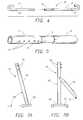
- FIG. 1is a perspective view of a truck bed rack according to the present invention, in the process of being installed on a pickup truck;
- FIG. 2is a view of the rack disassembled components, folded compactly for storage
- FIG. 3shows the rack folded components being fitted in a sack for storage on a truck
- FIG. 4is a side view of a side frame assembly in accordance with the present invention, showing its two mating frame sections separately;
- FIG. 5shows detail of side frame part connection thereof
- FIG. 6is a perspective view of an end frame assembly in accordance with the present invention.
- FIG. 7Ais a front elevation view of a leg member that is part of an end frame assembly
- FIG. 7Bis a side elevation view thereof, particularly showing a pivotable support strut for connection to a side frame assembly;
- FIG. 7Cis a side elevation view of a leg member, particularly showing an alternate pivotable connection to its base;
- FIG. 8is a perspective view of a cross frame assembly, showing its two telescoping frame members separately;
- FIGS. 8A and 8Billustrate the method of joining a cross frame assembly to the top of a leg stanchion, particularly showing the action of spring-loaded pins in holding the parts together;
- FIG. 9is a detailed illustration of connecting one end of a side frame assembly to an end frame assembly
- FIG. 10is a cross-section view of a typical spring-loaded pin configuration which is used for holding all the frame assemblies to each other;
- FIG. 11is an end cross-section view of the method of joining one end of a side frame assembly to an end frame assembly
- FIG. 12is a view-of a frame leg base that is fastened to the side wall of a pickup truck for installation.
- FIG. 13is a cross-section view taken along line 13 — 13 of FIG. 12, particularly showing the leg base portion bolted to an anchor device that is attached in the wall of a pickup truck.
- FIG. 1a truck bed rack 1 , according to the present invention installed on the sides 4 of a pickup truck 6 , except for one side frame assembly 8 .
- This side frame assembly 8would be fastened at each end to the end frame assemblies 10 , using fixed bolt levers 30 attached to the side frame assembly.
- a strut 16 that is mounted on each support stanchionwould then be pivoted and snapped on to the side frame assembly 8 , holding the side frame assembly 8 rigidly in place.
- the four support stanchions that are parts of the two end frame assemblies 10are each fastened at their base to the sides 4 of the truck 6 . This is done by turning a ring-headed screw 34 into a small sized stake pocket anchor 36 that is permanently fixed to the truck sides 4 below the side top surface.
- the completed rack 1is made using steel tubing and steel sheet parts. It is rigid and strong enough to support items such as wood planks, sheets or ladders such as may be found in typical building material supply stores for “do-it-yourself” homeowners as well as for professional building contractors.
- Each side frame assembly 8has looped ends that may be used for carried article retention or securing.
- the rack features that make these short times possibleare:
- FIG. 2shows how the major rack assemblies are further disassembled and arranged for packing.
- the two end frame assemblies 10each have their cross frame assembly 12 removed by depressing connecting end spring-pins.
- the remaining four leg assemblies 14are then stacked together as shown.
- the two side frame assemblies 8are each disconnected into two parts and arranged as shown. This leaves four leg base fastening bolts 34 which may be put into a small plastic bag. The above procedure can be performed very quickly if necessary, again without any tools.
- FIG. 3shows the rack 1 subassemblies being placed in a sack 3 for compact storage in the cab of a pickup truck or other area.
- FIGS. 4 and 5are respectively, an exploded view of the side frame assembly 8 and a detailed view of the frame assembly joining area.
- the side frame assembly 8comprises two mating elements that engage telescopically: a tubular insert member 9 and a tubular receptor member 11 . Both the insert member 9 and receptor member 11 have one end that is curved back in a loop. This looped end is provided to retain articles carried on top of the rack from sliding off the ends. The loops may also be used for tieing articles to an installed rack 1 .
- the insert member 9has a stepped down diameter portion 7 on its end distal to the looped end, sized to fit inside the mating end of the receptor member 11 .
- a spring-loaded push pin 15Located near the end of the stepped down portion 7 is a spring-loaded push pin 15 , that fits in any of five aperture holes 17 in the receptor member 11 wall for joining the two members. This arrangement is primarily for facilitating any adjustment in length that a user may need to make when initially installing a side frame assembly 8 on the end frame assemblies 10 over a truck bed. Normally, a side frame assembly 8 would not be disassembled into two members unless it was intended to pack the assembly parts for storage.
- Another spring-loaded push pin 15is located on the insert and receptor members near to their looped end, for the purpose of fastening to a frame stiffening strut.
- a through holeis also provided in each member, located in its looped end for connecting the side frame assembly 8 by a levered screw bolt 30 to an open corner of an end frame assembly 10 as depicted in FIG. 1 .
- the end frame assembly 10 as depicted in FIG. 6comprises two identical leg members 14 and a cross frame assembly 12 . Pivotably attached to each leg member 14 is a strut 16 that is used to fasten to a side frame assembly 8 for stiffening purposes.
- the strut 16may be arcuate in cross-section medially at extremities.
- a leg member 14is shown in front view in FIG. 7 A and side view in FIG. 7 B.
- Each leg member 14comprises a support stanchion 18 , a leg base member 20 that is joined to the bottom of the stanchion 18 , a strut 16 that is pivotably mounted at one end to the side of the stanchion 18 , an end plug 19 that is located inside the top end of the stanchion 18 , and four spring-loaded push pins 15 as a means for joining a leg member 14 to a cross frame assembly 12 .
- FIG. 7Cdepicts an alternate method of joining a leg member 14 stanchion to a base member 20 , by connecting the lower end of the stanchion to a pivot pin 63 that is secured to a tang 61 projecting above the base member 20 , thereby allowing the stanchion to be pivoted about the base through a small angle.
- the stanchion 18is angled with respect to the horizontal plane of the leg base member 20 by about 75 degrees, so that the leg member 14 , when connected at its top end to a cross frame assembly 12 , will project downward and outward at an angle of about 105 degrees as depicted in FIGS. 1 and 6. This is done to provide strong support for the rack top members and the end frame assembly 10 .
- Two holes 21are cut through the base member 20 for the fastening screws used to fasten the leg members to the top sides of a pickup truck.
- FIG. 8is a perspective view of the two mating parts forming a cross frame assembly 12 .
- the two partsare a tubular end insert member 23 and a tubular end receptor member 25 . Both members are identical in size and construction with the exception of their mating ends.
- the insert member 23 endhas a reduced diameter portion 28 that includes a spring-loaded push pin.
- the receptor member 25 endincludes several holes in its wall, lined up to receive a push pin when the two members are joined. In assembly the insert member 23 and the receptor member 25 engage telescopically, permitting the overall length of the cross frame assembly to be adjusted in length.
- Both members 23 , 25have welded to their distal ends, two paralleled gusset plates 26 .
- Two holes 27are cut in each gusset plate, near its projecting edge as a means of connecting with spring-loaded push pins 15 near the top of each leg stanchion 18 . This connection method is illustrated in FIGS. 8A and 8B.
- FIGS. 9 and 11show a side frame assembly 8 being secured to a corner of an end frame assembly.
- FIG. 11is a cross-section view of the corner connection as in FIG. 9 .
- the top corners of the rackare made rigid by the combined action of the gussets 26 which are welded to the cross frame members, bearing against the angled outward leg members 18 in one direction; the struts 16 bearing outward in a plane 90 degrees to the plane of the gussets 26 and angled upward against the side frame 8 members, and finally the end portions of the side frame 8 which are seated in and screwed tightly down into the open corners that are formed by end frames and leg members.
- the corner membersare thus prevented from moving apart sideways, and the frame corners become absolutely immoveable downwards when the rack is mounted, regardless of applied top down pressure.
- a frame bolt 32incorporates a bolt lever 30 that extends radially therefrom and is used to fasten the side frame assembly 8 to the corner; the bolt 32 being turned into a threaded hole in a tube end piece 19 located just inside the top end of a leg stanchion 18 .
- the bolt 32is preferably axially aligned with the stanchion 18 along its long axis, although an angled entry into the tube end piece 19 as shown is within the ambit of the present invention.
- a strut 16is pivoted on the stanchion 18 , and fastened to the side frame assembly 8 , using strut end holes 17 connected to two spring-loaded push pins 15 as shown in the partial cross-section view of FIG. 10 .
- each bolt 32takes substantially all play out of the adjustable elements such as telescoping tubes and spring loaded pins, creating a shearing action that jams the spring pins into the sides of their holes and producing a remarkably rigid structure.
- FIGS. 12 and 13show how the leg base member 20 is fastened to the side 4 of a pickup truck.
- a base bolt having a ring top portion 34is inserted through a hole in the base member 20 and screwed into a stake pocket anchor device 36 that is permanently attached to the side 4 of the truck.
- the stake pocket anchor 36is a readily available device that is described by U.S. Pat. No. 5,326,203 and which is hereby incorporated herein. This anchor device avoids any need to use a rail or any base fastening device that would permanently project above the sides of a pickup truck as commonly used by many available racks.
- All structural members of the rack excepting gussets, struts and leg bases,are preferably made of steel tubing for strength.
- the gussets, struts and leg basesare made from steel sheet.
- aluminumcould be used for the rack structural elements.
- the fastening boltshowever would still need to be made of steel.
- the rack 1would remain relatively easy and fast to install or disassemble for packing away.
- the rack design as described aboveincorporates an ability to be adjusted to fit several sizes of pickup truck body lengths and widths. It is simple in configuration, using no complex parts requiring special machining, and uses standard available fastening components. It is therefore economical to manufacture and could be made available to small pickup truck owners at a relatively low cost. It is also clear from the above description, that the rack is obviously easy to install, remove and store by any adult without tools or using much manual strength, as has been previously demonstrated by the inventor.
Landscapes
- Engineering & Computer Science (AREA)
- Mechanical Engineering (AREA)
- Assembled Shelves (AREA)
Abstract
Description
Claims (9)
Priority Applications (1)
| Application Number | Priority Date | Filing Date | Title |
|---|---|---|---|
| US09/630,726US6347731B1 (en) | 2000-08-02 | 2000-08-02 | Easily removable pickup truck bed rack |
Applications Claiming Priority (1)
| Application Number | Priority Date | Filing Date | Title |
|---|---|---|---|
| US09/630,726US6347731B1 (en) | 2000-08-02 | 2000-08-02 | Easily removable pickup truck bed rack |
Publications (1)
| Publication Number | Publication Date |
|---|---|
| US6347731B1true US6347731B1 (en) | 2002-02-19 |
Family
ID=24528354
Family Applications (1)
| Application Number | Title | Priority Date | Filing Date |
|---|---|---|---|
| US09/630,726Expired - Fee RelatedUS6347731B1 (en) | 2000-08-02 | 2000-08-02 | Easily removable pickup truck bed rack |
Country Status (1)
| Country | Link |
|---|---|
| US (1) | US6347731B1 (en) |
Cited By (54)
| Publication number | Priority date | Publication date | Assignee | Title |
|---|---|---|---|---|
| US6536640B1 (en)* | 2000-08-07 | 2003-03-25 | Gloria J. Gent | Tote all |
| US6607228B2 (en)* | 2001-12-18 | 2003-08-19 | Markets Direct, Inc. | Storage apparatus for automobiles |
| US6752301B1 (en) | 2002-08-30 | 2004-06-22 | Thomas A. Drolet | Collapsible rack for use in truck beds |
| US20040232718A1 (en)* | 2003-05-20 | 2004-11-25 | Kerns Christopher Lynn | Pickup truck recreational equipment rack |
| US20040262348A1 (en)* | 2003-06-30 | 2004-12-30 | Green Christopher Phillip | Utility rack for pickup trucks |
| US20060033359A1 (en)* | 2004-08-13 | 2006-02-16 | William Taylor | Structurally independent load bearing support system |
| US20080003044A1 (en)* | 2004-01-06 | 2008-01-03 | Brother Kogyo Kabushiki Kaisha | Roll sheet holder and tape printer |
| US7338110B1 (en)* | 2004-03-18 | 2008-03-04 | Donald Eckloff | Rack and shelf system for cargo vehicles |
| US20090026784A1 (en)* | 2003-06-27 | 2009-01-29 | Christopher Phillip Green | Disassemblable truck rack having gusset and improved bedrail mounting system |
| US20090166390A1 (en)* | 2007-10-26 | 2009-07-02 | Joseph Flaherty | Over cab extension kit |
| US7641251B1 (en) | 2007-06-29 | 2010-01-05 | Goorgen Stepanians | Collapsible truck rack and method of use |
| US20100288808A1 (en)* | 2009-05-18 | 2010-11-18 | Tracrac, Inc. | Modular rack system with gussetless joints |
| US7971847B1 (en)* | 2006-03-15 | 2011-07-05 | Azimuth, Inc. | Roof rack and roof rack system for a portable shelter |
| US20120080901A1 (en)* | 2010-10-01 | 2012-04-05 | Jake Izydorek | Vehicular storage system |
| US8162367B2 (en)* | 2010-05-19 | 2012-04-24 | Dale Raymond Kuklok | Rack with retractable drawers for the bed of a pick-up truck |
| US8251423B1 (en)* | 2008-12-12 | 2012-08-28 | Lingle James R | Truck bed handle assembly |
| US20130181023A1 (en)* | 2012-01-12 | 2013-07-18 | Armando Shawanda | Truck bed winch mount device |
| US20130186923A1 (en)* | 2012-01-23 | 2013-07-25 | Heath Gier | Automotive cargo carrying systems |
| US20130300143A1 (en)* | 2012-05-11 | 2013-11-14 | James Dunn | Truck bed payload support and method of use |
| US8668125B2 (en) | 2011-07-28 | 2014-03-11 | Daws Manufacturing Co., Inc. | Vehicle rack system |
| US20150183363A1 (en)* | 2013-12-27 | 2015-07-02 | Jerome Puchkoff | Utility rack and rail system for vehicle |
| US20160059906A1 (en)* | 2014-08-27 | 2016-03-03 | Bernhard Leitner | Modular truck bed rack system and portions thereof |
| US20170355480A1 (en)* | 2015-01-11 | 2017-12-14 | Eco Pack Green Box Usa Llc | Compactly Transportable Collapsible Frame |
| US9914403B1 (en)* | 2015-10-04 | 2018-03-13 | Star Headlight & Latern Co., Inc. | Bracket for freestand mounting an optical warning device to side of a truck bed |
| USD813787S1 (en) | 2016-06-13 | 2018-03-27 | Ronald D. Thomas | Cargo rack |
| AT15694U1 (en)* | 2016-10-20 | 2018-04-15 | Cs Powermetall Christian Stoeckl | Pickup vehicle body with integrated drawers |
| US20180154817A1 (en)* | 2016-07-25 | 2018-06-07 | Kevin M. Chambers | Truck ladder rack |
| US10000114B2 (en) | 2015-01-22 | 2018-06-19 | A.R.E. Accessories | Truck cap with heavy duty mounting rack |
| US10093243B2 (en)* | 2016-11-17 | 2018-10-09 | King Roof Industrial Co., Ltd | Supporting structure and bike-carrying rack including the same |
| US10188890B2 (en) | 2013-12-26 | 2019-01-29 | Icon Health & Fitness, Inc. | Magnetic resistance mechanism in a cable machine |
| US10207650B1 (en)* | 2017-11-21 | 2019-02-19 | Arnold Banegas | Adjustable utility rack for trucks |
| US10252109B2 (en) | 2016-05-13 | 2019-04-09 | Icon Health & Fitness, Inc. | Weight platform treadmill |
| US10279212B2 (en) | 2013-03-14 | 2019-05-07 | Icon Health & Fitness, Inc. | Strength training apparatus with flywheel and related methods |
| US10293211B2 (en) | 2016-03-18 | 2019-05-21 | Icon Health & Fitness, Inc. | Coordinated weight selection |
| US10322662B2 (en)* | 2016-10-03 | 2019-06-18 | Brent Lasley | Kayak transport dolly and storage rack |
| US20190256156A1 (en)* | 2018-02-20 | 2019-08-22 | Dee Zee, Inc. | Adaptable truck bed storage systems |
| US10426989B2 (en) | 2014-06-09 | 2019-10-01 | Icon Health & Fitness, Inc. | Cable system incorporated into a treadmill |
| US10441840B2 (en) | 2016-03-18 | 2019-10-15 | Icon Health & Fitness, Inc. | Collapsible strength exercise machine |
| US10449416B2 (en) | 2015-08-26 | 2019-10-22 | Icon Health & Fitness, Inc. | Strength exercise mechanisms |
| US20190367101A1 (en)* | 2018-06-01 | 2019-12-05 | Yakima Products, Inc. | Truck-mountable cargo rack |
| US10556534B2 (en) | 2016-10-24 | 2020-02-11 | Ford Global Technologies, Llc | Apparatus and method for transporting cargo over a cargo bed |
| US10661114B2 (en) | 2016-11-01 | 2020-05-26 | Icon Health & Fitness, Inc. | Body weight lift mechanism on treadmill |
| US10940360B2 (en) | 2015-08-26 | 2021-03-09 | Icon Health & Fitness, Inc. | Strength exercise mechanisms |
| WO2021055734A1 (en)* | 2019-09-18 | 2021-03-25 | Overkill Motorsports, Inc. | Reconfigurable bed rack system and method |
| US11142132B2 (en)* | 2019-06-21 | 2021-10-12 | Forcome (Zhejiang) Co., Ltd. | Vehicle rack |
| US11214209B2 (en) | 2018-06-13 | 2022-01-04 | Isabrem Ltd. | Rack of unitary one-piece construction |
| USD951850S1 (en) | 2019-10-24 | 2022-05-17 | Overkill Motorsports, Inc. | Truck bed rack |
| US20220348269A1 (en)* | 2021-04-30 | 2022-11-03 | Tomas Horacio Bello Flores | Modular Support Assembly for a Vehicle Bed or Cabin |
| US20230108330A1 (en)* | 2021-10-05 | 2023-04-06 | Trukd, Llc | Modular truck bed rack system and related methods |
| US20230136740A1 (en)* | 2021-10-29 | 2023-05-04 | Extang Corporation | Adjustable vehicle rack |
| US20230173990A1 (en)* | 2021-12-06 | 2023-06-08 | Forcome (Zhejiang) Co., Ltd. | Pickup truck rack |
| US11731564B1 (en) | 2022-02-25 | 2023-08-22 | Paul W. Strawn | Pickup truck rack |
| USD997838S1 (en) | 2020-09-18 | 2023-09-05 | Bernhard Leitner | Truck bed rack support |
| USD1092355S1 (en) | 2022-10-13 | 2025-09-09 | Andrew Cleland | Folding safety handrail |
Citations (10)
| Publication number | Priority date | Publication date | Assignee | Title |
|---|---|---|---|---|
| US4138046A (en)* | 1975-04-04 | 1979-02-06 | Freze William E De | Demountable truck bed load-supporting rack |
| US5037152A (en)* | 1990-10-26 | 1991-08-06 | Pwhh, Inc. | Collapsible truck rack |
| US5108141A (en)* | 1989-11-13 | 1992-04-28 | Anderson Leona F | Demountable rack for trucks with canopies |
| US5143415A (en)* | 1991-05-31 | 1992-09-01 | Jemb Rack Systems, Inc. | Disassemblable, lightweight truck utility rack |
| US5152570A (en)* | 1991-11-04 | 1992-10-06 | Hood Billy J | Retractable cargo rack |
| US5431472A (en)* | 1992-08-25 | 1995-07-11 | Technic Tool Corporation | Convertible pickup side rail apparatus |
| US5439152A (en)* | 1994-05-16 | 1995-08-08 | Campbell; Samuel | Extendable carrier rack for pick-up trucks |
| US5725137A (en)* | 1996-06-17 | 1998-03-10 | Macdonald; Brian | Carrier rack and rack retainer |
| US5836635A (en)* | 1996-05-31 | 1998-11-17 | Dorman; John R. | Knockdown truck rack apparatus and method |
| US5927782A (en)* | 1998-02-25 | 1999-07-27 | Tailgater | Overhead truck rack and corner bracket |
- 2000
- 2000-08-02USUS09/630,726patent/US6347731B1/ennot_activeExpired - Fee Related
Patent Citations (10)
| Publication number | Priority date | Publication date | Assignee | Title |
|---|---|---|---|---|
| US4138046A (en)* | 1975-04-04 | 1979-02-06 | Freze William E De | Demountable truck bed load-supporting rack |
| US5108141A (en)* | 1989-11-13 | 1992-04-28 | Anderson Leona F | Demountable rack for trucks with canopies |
| US5037152A (en)* | 1990-10-26 | 1991-08-06 | Pwhh, Inc. | Collapsible truck rack |
| US5143415A (en)* | 1991-05-31 | 1992-09-01 | Jemb Rack Systems, Inc. | Disassemblable, lightweight truck utility rack |
| US5152570A (en)* | 1991-11-04 | 1992-10-06 | Hood Billy J | Retractable cargo rack |
| US5431472A (en)* | 1992-08-25 | 1995-07-11 | Technic Tool Corporation | Convertible pickup side rail apparatus |
| US5439152A (en)* | 1994-05-16 | 1995-08-08 | Campbell; Samuel | Extendable carrier rack for pick-up trucks |
| US5836635A (en)* | 1996-05-31 | 1998-11-17 | Dorman; John R. | Knockdown truck rack apparatus and method |
| US5725137A (en)* | 1996-06-17 | 1998-03-10 | Macdonald; Brian | Carrier rack and rack retainer |
| US5927782A (en)* | 1998-02-25 | 1999-07-27 | Tailgater | Overhead truck rack and corner bracket |
Cited By (90)
| Publication number | Priority date | Publication date | Assignee | Title |
|---|---|---|---|---|
| US6536640B1 (en)* | 2000-08-07 | 2003-03-25 | Gloria J. Gent | Tote all |
| US6607228B2 (en)* | 2001-12-18 | 2003-08-19 | Markets Direct, Inc. | Storage apparatus for automobiles |
| US20040036321A1 (en)* | 2001-12-18 | 2004-02-26 | Markets Direct, Inc. | Storage apparatus for automobiles |
| US6959955B2 (en)* | 2001-12-18 | 2005-11-01 | Markets Direct, Inc. | Storage apparatus for automobiles |
| US6752301B1 (en) | 2002-08-30 | 2004-06-22 | Thomas A. Drolet | Collapsible rack for use in truck beds |
| US7014236B2 (en)* | 2003-05-20 | 2006-03-21 | Christopher L. Kerns | Pickup truck recreational equipment rack |
| US20040232718A1 (en)* | 2003-05-20 | 2004-11-25 | Kerns Christopher Lynn | Pickup truck recreational equipment rack |
| US20090026784A1 (en)* | 2003-06-27 | 2009-01-29 | Christopher Phillip Green | Disassemblable truck rack having gusset and improved bedrail mounting system |
| US20040262348A1 (en)* | 2003-06-30 | 2004-12-30 | Green Christopher Phillip | Utility rack for pickup trucks |
| US7419075B2 (en)* | 2003-06-30 | 2008-09-02 | Christopher Phillip Green | Utility rack for pickup trucks |
| US20080003044A1 (en)* | 2004-01-06 | 2008-01-03 | Brother Kogyo Kabushiki Kaisha | Roll sheet holder and tape printer |
| US7338110B1 (en)* | 2004-03-18 | 2008-03-04 | Donald Eckloff | Rack and shelf system for cargo vehicles |
| US20060033351A1 (en)* | 2004-08-13 | 2006-02-16 | William Taylor | Structurally independent load bearing support system |
| US7182396B2 (en)* | 2004-08-13 | 2007-02-27 | Jdm Ventures, Llc | Structurally independent load bearing support system |
| US7219952B2 (en)* | 2004-08-13 | 2007-05-22 | Jdm Venture, Llc | Structurally independent load bearing support system |
| US20060033359A1 (en)* | 2004-08-13 | 2006-02-16 | William Taylor | Structurally independent load bearing support system |
| US7971847B1 (en)* | 2006-03-15 | 2011-07-05 | Azimuth, Inc. | Roof rack and roof rack system for a portable shelter |
| US7641251B1 (en) | 2007-06-29 | 2010-01-05 | Goorgen Stepanians | Collapsible truck rack and method of use |
| US20090166390A1 (en)* | 2007-10-26 | 2009-07-02 | Joseph Flaherty | Over cab extension kit |
| US8322582B2 (en)* | 2007-10-26 | 2012-12-04 | Thule Sweden Ab | Over cab extension kit |
| US8251423B1 (en)* | 2008-12-12 | 2012-08-28 | Lingle James R | Truck bed handle assembly |
| US9834258B2 (en) | 2009-05-18 | 2017-12-05 | Thule, Inc. | Modular rack system with gussetless joints |
| US20140305979A1 (en)* | 2009-05-18 | 2014-10-16 | Thule Inc. | Modular rack system with gussetless joints |
| US9981612B2 (en)* | 2009-05-18 | 2018-05-29 | Thule Inc. | Modular rack system with gussetless joints |
| US20100288808A1 (en)* | 2009-05-18 | 2010-11-18 | Tracrac, Inc. | Modular rack system with gussetless joints |
| US9566914B2 (en)* | 2009-05-18 | 2017-02-14 | Thule Inc. | Modular rack system with gussetless joints |
| US10543790B2 (en) | 2009-05-18 | 2020-01-28 | Thule, Inc. | Modular rack system with gussetless joints |
| US8162367B2 (en)* | 2010-05-19 | 2012-04-24 | Dale Raymond Kuklok | Rack with retractable drawers for the bed of a pick-up truck |
| US9016750B2 (en)* | 2010-10-01 | 2015-04-28 | Cap-Pack Truck Products Llc | Vehicular storage system |
| US9902329B2 (en) | 2010-10-01 | 2018-02-27 | Cap-Pack Truck Products Llc | Vehicular storage system |
| US20120080901A1 (en)* | 2010-10-01 | 2012-04-05 | Jake Izydorek | Vehicular storage system |
| US8668125B2 (en) | 2011-07-28 | 2014-03-11 | Daws Manufacturing Co., Inc. | Vehicle rack system |
| US20130181023A1 (en)* | 2012-01-12 | 2013-07-18 | Armando Shawanda | Truck bed winch mount device |
| US8814015B2 (en)* | 2012-01-23 | 2014-08-26 | Heath Gier | Automotive cargo carrying systems |
| US20130186923A1 (en)* | 2012-01-23 | 2013-07-25 | Heath Gier | Automotive cargo carrying systems |
| US20130300143A1 (en)* | 2012-05-11 | 2013-11-14 | James Dunn | Truck bed payload support and method of use |
| US10279212B2 (en) | 2013-03-14 | 2019-05-07 | Icon Health & Fitness, Inc. | Strength training apparatus with flywheel and related methods |
| US10188890B2 (en) | 2013-12-26 | 2019-01-29 | Icon Health & Fitness, Inc. | Magnetic resistance mechanism in a cable machine |
| US9580004B2 (en)* | 2013-12-27 | 2017-02-28 | Jerome Puchkoff | Utility rack and rail system for vehicle |
| EP3086981A4 (en)* | 2013-12-27 | 2018-01-10 | Puchkoff, Jerome | Utility rack and rail system for vehicle |
| US20150183363A1 (en)* | 2013-12-27 | 2015-07-02 | Jerome Puchkoff | Utility rack and rail system for vehicle |
| US10426989B2 (en) | 2014-06-09 | 2019-10-01 | Icon Health & Fitness, Inc. | Cable system incorporated into a treadmill |
| US12420872B2 (en) | 2014-08-27 | 2025-09-23 | Bernhard Leitner | Modular truck bed rack system and portions thereof |
| US11851111B2 (en) | 2014-08-27 | 2023-12-26 | Bernhard Leitner | Modular truck bed rack system and portions thereof |
| US11377160B2 (en) | 2014-08-27 | 2022-07-05 | Bernhard Leitner | Modular truck bed rack system and portions thereof |
| US10793200B2 (en) | 2014-08-27 | 2020-10-06 | Bernhard Leitner | Modular truck bed rack system and portions thereof |
| US9586629B2 (en)* | 2014-08-27 | 2017-03-07 | Bernhard Leitner | Modular truck bed rack system and portions thereof |
| US20160059906A1 (en)* | 2014-08-27 | 2016-03-03 | Bernhard Leitner | Modular truck bed rack system and portions thereof |
| US20170355480A1 (en)* | 2015-01-11 | 2017-12-14 | Eco Pack Green Box Usa Llc | Compactly Transportable Collapsible Frame |
| US10000114B2 (en) | 2015-01-22 | 2018-06-19 | A.R.E. Accessories | Truck cap with heavy duty mounting rack |
| US10449416B2 (en) | 2015-08-26 | 2019-10-22 | Icon Health & Fitness, Inc. | Strength exercise mechanisms |
| US10940360B2 (en) | 2015-08-26 | 2021-03-09 | Icon Health & Fitness, Inc. | Strength exercise mechanisms |
| US9914403B1 (en)* | 2015-10-04 | 2018-03-13 | Star Headlight & Latern Co., Inc. | Bracket for freestand mounting an optical warning device to side of a truck bed |
| US10293211B2 (en) | 2016-03-18 | 2019-05-21 | Icon Health & Fitness, Inc. | Coordinated weight selection |
| US10441840B2 (en) | 2016-03-18 | 2019-10-15 | Icon Health & Fitness, Inc. | Collapsible strength exercise machine |
| US10252109B2 (en) | 2016-05-13 | 2019-04-09 | Icon Health & Fitness, Inc. | Weight platform treadmill |
| USD813787S1 (en) | 2016-06-13 | 2018-03-27 | Ronald D. Thomas | Cargo rack |
| US20180154817A1 (en)* | 2016-07-25 | 2018-06-07 | Kevin M. Chambers | Truck ladder rack |
| US10421385B2 (en)* | 2016-07-25 | 2019-09-24 | Kevin M. Chambers | Truck ladder rack |
| US10322662B2 (en)* | 2016-10-03 | 2019-06-18 | Brent Lasley | Kayak transport dolly and storage rack |
| AT15694U1 (en)* | 2016-10-20 | 2018-04-15 | Cs Powermetall Christian Stoeckl | Pickup vehicle body with integrated drawers |
| US10556534B2 (en) | 2016-10-24 | 2020-02-11 | Ford Global Technologies, Llc | Apparatus and method for transporting cargo over a cargo bed |
| US10661114B2 (en) | 2016-11-01 | 2020-05-26 | Icon Health & Fitness, Inc. | Body weight lift mechanism on treadmill |
| US10093243B2 (en)* | 2016-11-17 | 2018-10-09 | King Roof Industrial Co., Ltd | Supporting structure and bike-carrying rack including the same |
| US10207650B1 (en)* | 2017-11-21 | 2019-02-19 | Arnold Banegas | Adjustable utility rack for trucks |
| CN111741870A (en)* | 2018-02-20 | 2020-10-02 | 迪泽股份有限公司 | Adaptable truck bed storage system |
| US11459038B2 (en) | 2018-02-20 | 2022-10-04 | Dee Zee, Inc. | Adaptable truck bed storage systems |
| US10800465B2 (en)* | 2018-02-20 | 2020-10-13 | Dee Zee, Inc. | Adaptable truck bed storage systems |
| US20190256156A1 (en)* | 2018-02-20 | 2019-08-22 | Dee Zee, Inc. | Adaptable truck bed storage systems |
| AU2023266262B2 (en)* | 2018-06-01 | 2025-07-10 | Yakima Australia Pty Limited | Truck-Mountable Cargo Rack |
| US20190367101A1 (en)* | 2018-06-01 | 2019-12-05 | Yakima Products, Inc. | Truck-mountable cargo rack |
| US20220001938A1 (en)* | 2018-06-01 | 2022-01-06 | Yakima Products, Inc. | Truck-mountable cargo rack |
| US20220017155A1 (en)* | 2018-06-01 | 2022-01-20 | Yakima Products, Inc. | Truck-mountable cargo rack |
| US12128959B2 (en)* | 2018-06-01 | 2024-10-29 | Yakima Products, Inc. | Truck-mountable cargo rack |
| US11072376B2 (en)* | 2018-06-01 | 2021-07-27 | Yakima Products, Inc. | Truck-mountable cargo rack |
| US20190367100A1 (en)* | 2018-06-01 | 2019-12-05 | Yakima Products, Inc. | Truck-mountable cargo rack |
| US11541948B2 (en)* | 2018-06-01 | 2023-01-03 | Yakima Products, Inc. | Truck-mountable cargo rack |
| US11214209B2 (en) | 2018-06-13 | 2022-01-04 | Isabrem Ltd. | Rack of unitary one-piece construction |
| US11142132B2 (en)* | 2019-06-21 | 2021-10-12 | Forcome (Zhejiang) Co., Ltd. | Vehicle rack |
| US11325664B2 (en) | 2019-09-18 | 2022-05-10 | Overkill Motorsports, Inc. | Reconfigurable bed rack system and method |
| WO2021055734A1 (en)* | 2019-09-18 | 2021-03-25 | Overkill Motorsports, Inc. | Reconfigurable bed rack system and method |
| USD951850S1 (en) | 2019-10-24 | 2022-05-17 | Overkill Motorsports, Inc. | Truck bed rack |
| USD997838S1 (en) | 2020-09-18 | 2023-09-05 | Bernhard Leitner | Truck bed rack support |
| US20220348269A1 (en)* | 2021-04-30 | 2022-11-03 | Tomas Horacio Bello Flores | Modular Support Assembly for a Vehicle Bed or Cabin |
| US20230108330A1 (en)* | 2021-10-05 | 2023-04-06 | Trukd, Llc | Modular truck bed rack system and related methods |
| US12311889B2 (en)* | 2021-10-05 | 2025-05-27 | Trukd, Llc | Modular truck bed rack system and related methods |
| US20230136740A1 (en)* | 2021-10-29 | 2023-05-04 | Extang Corporation | Adjustable vehicle rack |
| US20230173990A1 (en)* | 2021-12-06 | 2023-06-08 | Forcome (Zhejiang) Co., Ltd. | Pickup truck rack |
| US11731564B1 (en) | 2022-02-25 | 2023-08-22 | Paul W. Strawn | Pickup truck rack |
| USD1092355S1 (en) | 2022-10-13 | 2025-09-09 | Andrew Cleland | Folding safety handrail |
Similar Documents
| Publication | Publication Date | Title |
|---|---|---|
| US6347731B1 (en) | Easily removable pickup truck bed rack | |
| US6712248B2 (en) | Foldable cargo carrying basket | |
| US6217043B1 (en) | Portable cart and method | |
| US20090056592A1 (en) | Combined cargo carrier and portable table | |
| US6659476B2 (en) | Horse tack cart | |
| US20090026784A1 (en) | Disassemblable truck rack having gusset and improved bedrail mounting system | |
| US6491195B1 (en) | Carrier device | |
| US5143415A (en) | Disassemblable, lightweight truck utility rack | |
| US6662983B2 (en) | Multi-configuration, multi-purpose rack system | |
| US7419075B2 (en) | Utility rack for pickup trucks | |
| US5560666A (en) | Removable rack system | |
| US5516020A (en) | Truck mount bicycle rack | |
| US5443586A (en) | Cargo restraint apparatus for a pick-up truck | |
| US20030222112A1 (en) | Carrier device | |
| US20060207831A1 (en) | Collapsible multi-use cart and tree stand | |
| US10583769B2 (en) | Modular bumper attachment | |
| US6524043B2 (en) | Adjustable cargo gate system | |
| US4565402A (en) | Truck bed support frame unit | |
| US20220227304A1 (en) | Truck Bed System | |
| US20240051471A1 (en) | Collapsible Vehicle Accessory Mount | |
| US9114758B1 (en) | Convertible cargo carrier and cart system | |
| US6270299B1 (en) | Carrier system for securing goods | |
| US20110259931A1 (en) | Auxiliary rack for an ATV | |
| CA2667845A1 (en) | Foldable truck bed extender | |
| US7168575B2 (en) | Ceiling mounted, adjustable motorcycle stabilizer |
Legal Events
| Date | Code | Title | Description |
|---|---|---|---|
| AS | Assignment | Owner name:HILLERICH & BRADSBY CO., KENTUCKY Free format text:MEMORANDUM OF ASSIGNMENT;ASSIGNOR:BURGER, GEORGE;REEL/FRAME:012342/0860 Effective date:20010301 | |
| FPAY | Fee payment | Year of fee payment:4 | |
| AS | Assignment | Owner name:PNC BANK, NATIONAL ASSOCIATION, OHIO Free format text:SECURITY AGREEMENT;ASSIGNOR:HILLERICH & BRADSBY & CO.;REEL/FRAME:022443/0676 Effective date:20081230 Owner name:PNC BANK, NATIONAL ASSOCIATION,OHIO Free format text:SECURITY AGREEMENT;ASSIGNOR:HILLERICH & BRADSBY & CO.;REEL/FRAME:022443/0676 Effective date:20081230 | |
| REMI | Maintenance fee reminder mailed | ||
| LAPS | Lapse for failure to pay maintenance fees | ||
| STCH | Information on status: patent discontinuation | Free format text:PATENT EXPIRED DUE TO NONPAYMENT OF MAINTENANCE FEES UNDER 37 CFR 1.362 | |
| FP | Expired due to failure to pay maintenance fee | Effective date:20100219 | |
| AS | Assignment | Owner name:HILLERICH & BRADSBY CO., KENTUCKY Free format text:REASSINMENT AND RELEASE OF SECURITY INTEREST-PATENTS;ASSIGNOR:PNC BANK, NATIONAL ASSOCIATION;REEL/FRAME:031709/0923 Effective date:20130809 | |
| AS | Assignment | Owner name:WELLS FARGO BANK, NATIONAL ASSOCIATION, NEW YORK Free format text:SECURITY AGREEMENT;ASSIGNOR:HILLERICH & BRADSBY CO.;REEL/FRAME:032817/0181 Effective date:20130809 | |
| AS | Assignment | Owner name:CRYSTAL FINANCIAL SBIC LP, MASSACHUSETTS Free format text:SECURITY INTEREST;ASSIGNOR:HILLERICH & BRADSBY CO.;REEL/FRAME:033258/0602 Effective date:20140627 | |
| AS | Assignment | Owner name:HILLERICH & BRADSBY, CO., KENTUCKY Free format text:RELEASE BY SECURED PARTY;ASSIGNOR:WELLS FARGO BANK, NATIONAL ASSOCIATION;REEL/FRAME:035476/0003 Effective date:20150421 | |
| AS | Assignment | Owner name:HILLERICH & BRADSBY, CO., KENTUCKY Free format text:RELEASE BY SECURED PARTY;ASSIGNOR:CRYSTAL FINANCIAL SBIC LP;REEL/FRAME:035485/0966 Effective date:20150421 |