US6344748B1 - Coaxial cable connector testing methods and apparatus - Google Patents
Coaxial cable connector testing methods and apparatusDownload PDFInfo
- Publication number
- US6344748B1 US6344748B1US09/511,038US51103800AUS6344748B1US 6344748 B1US6344748 B1US 6344748B1US 51103800 AUS51103800 AUS 51103800AUS 6344748 B1US6344748 B1US 6344748B1
- Authority
- US
- United States
- Prior art keywords
- coaxial cable
- circuit
- short
- open
- junctions
- Prior art date
- Legal status (The legal status is an assumption and is not a legal conclusion. Google has not performed a legal analysis and makes no representation as to the accuracy of the status listed.)
- Expired - Lifetime
Links
- 238000012360testing methodMethods0.000titleclaimsdescription83
- 238000000034methodMethods0.000claimsdescription8
- 230000008878couplingEffects0.000claimsdescription7
- 238000010168coupling processMethods0.000claimsdescription7
- 238000005859coupling reactionMethods0.000claimsdescription7
- 230000000007visual effectEffects0.000claimsdescription7
- 230000003213activating effectEffects0.000claimsdescription2
- 238000012544monitoring processMethods0.000claimsdescription2
- 239000004020conductorSubstances0.000abstractdescription11
- 230000001052transient effectEffects0.000description4
- 238000013461designMethods0.000description2
- 239000000463materialSubstances0.000description2
- 239000012528membraneSubstances0.000description2
- WHXSMMKQMYFTQS-UHFFFAOYSA-NLithiumChemical compound[Li]WHXSMMKQMYFTQS-UHFFFAOYSA-N0.000description1
- 239000003990capacitorSubstances0.000description1
- 230000015556catabolic processEffects0.000description1
- 230000001276controlling effectEffects0.000description1
- 230000002596correlated effectEffects0.000description1
- 230000002950deficientEffects0.000description1
- 238000006731degradation reactionMethods0.000description1
- 238000010586diagramMethods0.000description1
- 230000009977dual effectEffects0.000description1
- 238000005516engineering processMethods0.000description1
- 238000009434installationMethods0.000description1
- 229910052744lithiumInorganic materials0.000description1
- 238000012986modificationMethods0.000description1
- 230000004048modificationEffects0.000description1
- 230000010355oscillationEffects0.000description1
Images


Classifications
- G—PHYSICS
- G01—MEASURING; TESTING
- G01R—MEASURING ELECTRIC VARIABLES; MEASURING MAGNETIC VARIABLES
- G01R31/00—Arrangements for testing electric properties; Arrangements for locating electric faults; Arrangements for electrical testing characterised by what is being tested not provided for elsewhere
- G01R31/50—Testing of electric apparatus, lines, cables or components for short-circuits, continuity, leakage current or incorrect line connections
- G01R31/66—Testing of connections, e.g. of plugs or non-disconnectable joints
- G01R31/68—Testing of releasable connections, e.g. of terminals mounted on a printed circuit board
- G01R31/69—Testing of releasable connections, e.g. of terminals mounted on a printed circuit board of terminals at the end of a cable or a wire harness; of plugs; of sockets, e.g. wall sockets or power sockets in appliances
Definitions
- the present inventionrelates to a coaxial cable testing and, more particularly, to a coaxial cable testing methods and apparatus that detect intermittent and continuous opens and shorts at junctions between a coaxial cable and terminating coaxial cable connectors.
- the present inventionis generally applicable to all types of connectors for coaxial cables including bayonet coaxial cable (BNC) connectors, threaded connectors and other currently available coaxial cable connectors and connectors which may become available in the future.
- BNCbayonet coaxial cable
- field installed cables to be testedoften extend over hundreds of feet so that some prior art field testing devices require an installer at each end of the cable, one installer on one end of the cable with the testing device in hand in order to see or hear fault indications and the other installer at the other end of the cable to manipulate the coaxial cable connector on the other end of the cable.
- BERTBit Error Rate Test Set
- U.S. Pat. No. 4,553,085 to Canzanodiscloses a coaxial cable tester device which detects shorts and opens in either the center conductor or the ground conductor of a coaxial cable and indicates the defective conductor.
- U.S. Pat. No. 5,391,991 to Tuttlediscloses a cable shield resistance test set that measures degradation in cable shield without the need to disconnect the cable from the circuit.
- U.S. Pat. No. 5,477,152 to Hayhurstdiscloses a cable testing device that tests continuity and/or short circuits automatically in a cable.
- U.S. Pat. No. 5,565,784 to DeRennediscloses a coaxial cable testing and tracing device that allows the continuity of a plurality of coaxial cables to be tested and to individually locate a coaxial cable.
- the coaxial cable connector tester devicesubstantially departs from the conventional concepts and designs of the prior art, and in doing so provides an apparatus primarily developed for the purpose of testing for intermittent and continuous opens and shorts at the junction of the coaxial cable connector and the coaxial cable.
- the coaxial cable connector testeraccording to the present invention wherein a terminator plug is connected to one connector of a coaxial cable and the connector tester is connected to the other connector.
- the connector testerapplies a voltage to the center conductor of the coaxial cable and a ground to the shield with the voltage at the center conductor being monitored for open and short fault conditions while the cable adjacent first one and then the other connector of the cable are wiggled to test the integrity of the connection of the connectors to the cable.
- the voltage level on the center conductorchanges if either a short or open is present or intermittently occurs during the wiggle operation.
- the voltage on the center conductoris monitored by two comparator circuits with one detecting short faults, short comparator, and the other detecting open faults, open comparator.
- the outputs of the comparator circuitsare combined to generate an OK signal if no faults are detected. If open faults are detected, the signals from the open comparator are clocked into a flip-flop and if short faults are detected, the signals from the short comparator are clocked into a flip-flop. Outputs from the flip-flops are counted by respective open and short fault counters and displayed so that the number of intermittent open and short faults, if any, are displayed up to the capacity of the counter and a display used for the tester, 0-8 for the illustrated embodiment.
- a buzzercan also be used selectively to provide an audible fault signal if desired.
- a power management circuitprovides power to circuitry of the tester as demanded by a user and also monitors a battery so that an indication of low battery power can also be signaled to the user of the tester.
- a tester for junctions between a coaxial cable and coaxial cable connectors connected to the coaxial cable to test for intermittent and continuous open circuit and short circuit faults at the junctionscomprises a cable terminator plug having a characteristic impedance and being coupled to a first end of a coaxial cable whose junctions are to be tested.
- An electronic testing circuit having a coaxial cable connector coupled to a second end of the coaxial cable to be testedcomprises a test circuit coupled to the coaxial cable connector for detecting open and short circuit faults at one or both of the junctions.
- the electronic testing circuitgenerates open fault signals indicating detected open circuit faults, short fault signals indicating detected short faults and a no shorts/no opens signal indicating no detected short or open faults.
- An open counter coupled to the test circuitcounts the open fault signals and a short counter coupled to the test circuit counts the short fault signals.
- a display circuitdisplays the counts accumulated in the open counter and the short counter to indicated to a user the number of each type of fault up to the capacity of the counters and the display.
- the test circuitmay comprise a first comparator coupled to the coaxial cable connector for detecting the open circuit faults and a first storage device responsive to the open circuit faults generates the open fault signals.
- a second comparatoris coupled to the coaxial cable connector for detecting the short circuit faults and a second storage device responsive to the short circuit faults generates the short fault signals.
- Combination circuitryis coupled to the first and second storage devices for generating the no shorts/no opens signal.
- the storage devicesmay comprise flip-flop circuits and the tester may further comprise a battery with the tester being powered by the battery and a power management circuit for controlling power coupled from the battery to the electronic testing circuit. The power management circuit further monitors power of the battery and generates a visual warning displayed by the display circuit if a low power condition exists.
- the power management circuitprovides a first low power warning if the power is detected below a first threshold level and a second lower power warning if the power is detected below a second threshold level.
- the first threshold levelis approximately 2.6 volts
- the second threshold levelis approximately 2.45 volts.
- the power management circuitmay comprise an on switch and an off switch and pressing the on switch sets the open counter to a preset value and sets the short counter to a preset level.
- the preset value for the open counter and the short countercan be equal to zero.
- the display circuitmay be a quad seven segment LCD and may further comprise an audible sounder circuit which generates an audible indication if either the open fault signals or the short fault signals are generated.
- the audible sounder circuitmay comprise a buzzer and may further comprise an on switch and an off switch to turn the buzzer on and off, respectively.
- the electronic testing circuitis accommodated in a tester housing having a window for viewing the display circuit, and including a removable door to insert or remove a power supply battery also accommodated in the tester housing.
- a method for testing junctions between a coaxial cable and coaxial cable connectors connected to the coaxial cable for intermittent and continuous open circuit and short circuit faults at the junctionscomprises coupling a cable terminator plug having a characteristic impedance to a first end of a coaxial cable whose junctions are to be tested.
- An electronic testing circuit having a coaxial cable connectoris coupled to a second end of the coaxial cable to be tested by coupling a test circuit to the coaxial cable connector to detect open and short circuit faults at one or both of the junctions and to generate open fault signals indicating detected open circuit faults, short fault signals indicating detected short faults and a no shorts/no opens signal indicating no detected short or open faults.
- a an open counteris coupled to the test circuit for counting the open fault signals
- a short counteris coupled to the test circuit for counting the short fault signals.
- the counts accumulated in the open counter and the short counterare displayed to the cable installer testing the junctions.
- the methodmay further comprise providing a battery to power testing, monitoring power of the battery, and generating a visual warning displayed by a display circuit if a low power condition exists.
- the step of generating a visual warningmay comprise providing a first low power warning if the power is detected below a first threshold level, and providing a second lower power warning if the power is detected below a second threshold level.
- the methodmay further comprise providing an audible sounder circuit, and activating the audible sounder circuit to generate an audible indication if either the open fault signals or the short fault signals are generated.
- Another object of the present inventionis to provided a relatively inexpensive test set that detects intermittent or continuous opens or shorts at the junction of a coaxial cable connector and coaxial cable.
- Still another object of the present inventionis to provided a test set that detects intermittent or continuous opens or shorts at the junction of a coaxial cable connector and a coaxial cable that is non-bulky and easy to use in the field.
- FIG. 1is a front view of the present invention showing a tester housing attached to one end of a coaxial cable and a terminator plug attached to the other end of the cable.
- FIG. 2is a top view of the tester housing of FIG. 1 with the coaxial cable removed.
- FIG. 3is a schematic diagram of a currently preferred embodiment of a tester constructed in accordance with the principles of the present invention.
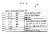
- FIG. 4is a tabulation illustrating examples of display indications in accordance with the principles of the present invention.
- the present inventioncomprises a plurality of components.
- such componentsinclude a coaxial terminator plug 12 , a tester housing 14 , and an electronic testing circuit 16 , see FIGS. 1-3.
- Such componentsare individually configured and correlated with respect to each other to provide the intended function of detecting intermittent or continuous opens or shorts at the junction of a coaxial cable connector and a coaxial cable.
- the coaxial cable connector testing device 10is a portable test instrument which electronically tests for intermittent or continuous short and open circuits to detect a damaged or faulty junction between a coaxial cable connector and a coaxial cable.
- the illustrated hand-held coaxial cable connector testing device 10is about 6 inches long by 3.5 inches wide by 1 inch thick.
- the present inventionemploys digital and analog integrated circuits powered by batteries that are contained in the tester housing 14 .
- the terminator plug 12is used in conjunction with the electronic testing circuit 16 .
- the terminator plug 12has a characteristic impedance of 10 kilo ohms.
- the terminator plug 12is configured to couple with a first coaxial cable connector 18 that is attached to a first end of a coaxial cable 20 .
- the tester housing 14is formed of a rigid impact-resistant plastic however other materials can be used.
- the tester housing 14includes an upper portion 22 that is removably coupled to a lower portion 24 . See FIG. 2 . When the portions are coupled together, a hollow interior is defined there between.
- the upper portion 22has a contoured top wall 26 with integral and rounded side walls 28 and 30 , and a plurality of side grooves 32 and 34 allowing the tester housing 14 to be conveniently held in the palm of a user's hand.
- the lower portion 24is substantially the same in shape as the upper portion 22 but includes a removable door 36 coupled thereto for allowing access to the hollow interior of the tester housing 14 , for example to insert or remove batteries.
- the electronic testing circuit 16is disposed within the tester housing 14 on a circuit broad (not shown).
- the electronic testing circuit 16includes a cable connector 40 .
- the cable connector 40extends from the tester housing 14 and connects to a second coaxial cable connector 42 that is attached to a second end of the coaxial cable 20 as shown in FIG. 1 .
- the connectorscan be coupled using threads, bayonet components or other appropriate connector technology.
- the electronic testing circuit 16includes a test circuit 44 .
- the test circuit 44is coupled to the cable connector 40 .
- the test circuit 44detects faults and generates one of three characteristic signals for the detected fault conditions.
- a first characteristic signal or OPEN-ERRORindicates that an open circuit condition has been detected at the cable connector 40 .
- a second characteristic signal or SHORT-ERRORindicates that a short circuit condition has been detected at the cable connector 40 .
- a third characteristic signal or OKAY-ERRORindicates that the coaxial cable 20 coupled to the cable connector 40 at one end and coupled at the opposite end with the terminator plug 12 has no intermittent or continuous shorts or opens.
- the test circuit 44includes two operational amplifiers 46 and 48 coupled to the cable connector 40 .
- the operational amplifiers 46 and 48are commercially available, for example a LM 339 dual OP AMP integrated circuit was used in a working embodiment of the present invention, and are operated in a comparator mode of operation to generate the above-mentioned three characteristic signals.
- Resistors 50 - 64configure the operational amplifiers 46 and 48 to generate output signals characteristic of the impedance seen at the cable connector 40 .
- the output signals from the operational amplifiers 46 and 48are fed to associated flip-flop circuits 66 and 68 , which are commercially available D flip-flops as illustrated.
- the flip-flop circuits 66 and 68have set and reset output states “1” and “0”, respectively, with the signals generated by the operational amplifiers 46 and 48 entering their associated flip-flop circuit 66 and 68 on the D lead to be clocked into the flip-flop circuits 66 and 68 by a clock signal generated by a clock circuit 70 .
- the flip-flop circuit 66When the flip-flop circuit 66 changes to the set output state “1” it provides a pulse signal that an open fault has been sensed by its associated operational amplifier 46 . Similarly, when the flip-flop 68 changes to the set output state “1” it provides a pulse signal that a short fault has been sensed by its associated operational amplifier 48 .
- the flip-flop circuits 66 and 68are “reset” if the faults are transient such that the inputs to the D-inputs of the flip-flops represent a “0” state which is then clocked into the flip-flops by a clock pulse generated by the clock circuit 70 . For transient faults, the output states of the flip-flop circuits are thus changed from the “0” to “1” state for each fault detected so that transient faults can be counted.
- the clock circuit 70generates clock pulses at an adjustable frequency, for example 70 hz was selected for a working embodiment. For this clock speed, transient errors on the order of 14 milliseconds can be detected and counted.
- the clock circuit 70is formed from a commercially available 555 timer in a known manner with the frequency of clock pulses being adjustable through conventional timer adjustment circuitry consisting of resistors and capacitors (not shown). As shown in FIG. 3, the clock pulses are fed to the flip-flop circuits 66 and 68 as clocking signals, and to both a display 72 and a signal display logic circuit 74 . A discussion of both the display 72 and the signal display logic circuit 74 is provided hereafter.
- Binary counters 76 and 78are also included in the electronic testing circuit 16 .
- the binary counters 76 and 78each comprise a commercially available CD4029 binary counter integrated circuit although other counter circuits can be used in the present invention.
- the input of the binary counters 76 and 78are coupled to the respective set outputs “1” of the flip-flop circuits 66 and 68 .
- the count of the binary counters 76 and 78are advanced one count for each pulse received from their respective flip-flop circuits 66 and 68 .
- the binary counters 76 and 78are reset to a preset level or logical “0” by a signal or logical “1” received on their reset inputs.
- the binary counts of the binary counters 76 and 78are coupled to the signal display logic circuit 74 .
- the binary counts from the binary counters 76 and 78are decoded by the signal display logic circuit 74 and displayed as a decimal number on the display 72 .
- the signal display logic circuit 74is formed of a 4511 IC to decode the binary counts.
- the signal display logic circuit 74also comprises a set of exclusive OR gate circuits, such as commercially available CD4030, in order to generate, in addition to the decimal counts of the binary counters 76 and 78 , display indications 80 tabulated in FIG. 4 . It is to be appreciate that a separate signal line from each flip-flip 66 and 68 is fed directly to an exclusive OR gate of the signal display logic in order to provide a continuous open and continuous short display indications 92 , 94 and 96 when detected.
- the resulting display indications 80 shown on the display 72are based on clock pulses from the clock circuit 70 , the outputs of the counters 76 and 78 , and a power management circuit 82 .
- a discussion of the power management circuit 82is provided later after a further discussion of the output of the signal display logic 74 , which follows.
- the output of the signal display logic circuit 74is fed to the display 72 which is visible to a user through a window 84 , made of clear plastic, provided in the upper portion 22 of the tester housing 14 , see FIG. 1 .
- the display 72is formed of a commercially available quad 7-segment display having three decimal points.
- a “short” seven segment display 86 for displaying detected shorts and an “open” seven segment display 88 for displaying detectedopens both of which can display a single number of “0”,“1”,“2”,“3”,“4”,“5”,“6”,“7”, or “8” based upon receipt of display signals from the signal display logic circuit 74 . If the number of faults detected exceeds eight, the binary counters 76 and 78 are configured to remain at a maximum count of “8” or alternately, the signal display logic circuit 74 is configured to display an “8” for all counts equal to or greater than eight.
- the display of an integer number of “0” in both the short seven segment display 86 and the open seven segment display 88indicates that the coaxial cable connectors 18 and 42 coupled to the coaxial cable 20 have no opens and no shorts.
- -” (representing a +) in the middle two seven segment displays 87 and 89indicates that the coaxial cable connection is good.
- All other display indications 92 - 102 tabulated in FIG. 4, along with the open count or the short count or both, other than a low battery warning 104 and a replace battery warning 106indicate a bad coaxial cable connection.
- the three decimal points 72 A, 72 B, 72 C of the display 72are used to indicate the current test status with the leftmost decimal point 72 A being displayed when a short fault condition is currently being detected, the rightmost decimal point 72 B being displayed when an open fault condition is currently being detected and the middle decimal point 72 C being flashed for indication of a low battery/replace battery warning.
- the electronic testing circuit 16can provide an audible warning by a buzzer circuit 108 with a buzzer 110 .
- the buzzer 110sounds whenever the third characteristic signal or OKAY-ERROR signal passed to the buzzer circuit 108 from the signal generator circuit 44 changes to a fault detect signal.
- a buzzer on switch 112 and a buzzer off switch 113preferably two commercially available membrane switches incorporated into a face cover for the testing device 10 , are provided to give the user the option of turning the buzzer on or off. It is to appreciated that a single buzzer on/off switch could be used if desired.
- a battery 116is disposed within the tester housing 14 for supplying electrical energy to the electronic testing circuit 16 .
- the battery 116is removably accessible through the removable door 36 of the tester housing 14 .
- the battery 116is conventional in design, commercially available, and preferably comprises two AA lithium batteries to provide 3 volts to the electronic testing circuit 16 .
- the above-mentioned power management circuit 82is included in the electronic testing circuit 16 and is coupled to the battery 116 to provide control of power to the electronic testing circuit 16 .
- the power management circuit 82consists of first and second switches 118 and 120 , preferably two commercially available membrane switches incorporated into the face cover for the testing device 10 .
- the first switch 118 of the power management circuit 82is used to turn the electronic testing circuit 16 on and to send a reset signal to the counters 76 and 78 at initialization and every time the first switch 118 is pressed.
- the second switch 120 of the power management circuit 82is used to turn the electronic testing circuit 16 off. It is to appreciated that a single power on/off switch could be used if desired.
- the power management circuit 82monitors the voltage of the battery 116 . If the voltage of the battery 116 drops below a first threshold voltage, preferably 2.6 volts, the power management circuit 82 will send an oscillating low battery signal to the signal display logic mechanism 74 which causes the display 72 to show the low battery warning by flashing the middle decimal point 72 C with the remainder or the display remaining the same. Thus, as shown in FIG. 4, the low battery voltage warning 104 , flashing of the middle decimal point 72 C, is shown with the remainder of the display showing a good coaxial cable connection display. Of course, any other cable connection display can be displayed with the low battery warning indication.
- the low battery signalis preferable provided to the signal display logic circuit 74 at a one second oscillation.
- the power management circuit 82will send a signal to the signal display logic mechanism 74 which causes the display 72 to show the replace battery warning 106 wherein the digit displays are turned off and the middle decimal point 72 C continues to flash.
- a userIn testing for intermittent or continuous short or open circuits at the coaxial cable connector coaxial cable junction, a user will terminate one end of the coaxial cable 20 to be tested with the terminator plug 12 . The user then secures the other end of the coaxial cable 20 to be tested to the cable connector 40 . It is to be appreciated that both ends of the coaxial cable have firmly attached coaxial cable connecters. With the coaxial cable connector testing device 10 turned on, the user wiggles one end of the coaxial cable in all directions for a few moments. After wiggling the coaxial cable 20 at one end, the user then checks the display 72 for one of the display indications 80 . Next, the user wiggles the other end of the coaxial cable 20 in all directions for a few moments and again checks the display 72 . If the coaxial cable 20 is to be re-checked, the user presses the on button once again to reset the coaxial cable connector testing device 10 .
Landscapes
- Physics & Mathematics (AREA)
- General Physics & Mathematics (AREA)
- Testing Of Short-Circuits, Discontinuities, Leakage, Or Incorrect Line Connections (AREA)
Abstract
Description
Claims (19)
Priority Applications (1)
| Application Number | Priority Date | Filing Date | Title |
|---|---|---|---|
| US09/511,038US6344748B1 (en) | 2000-02-23 | 2000-02-23 | Coaxial cable connector testing methods and apparatus |
Applications Claiming Priority (1)
| Application Number | Priority Date | Filing Date | Title |
|---|---|---|---|
| US09/511,038US6344748B1 (en) | 2000-02-23 | 2000-02-23 | Coaxial cable connector testing methods and apparatus |
Publications (1)
| Publication Number | Publication Date |
|---|---|
| US6344748B1true US6344748B1 (en) | 2002-02-05 |
Family
ID=24033203
Family Applications (1)
| Application Number | Title | Priority Date | Filing Date |
|---|---|---|---|
| US09/511,038Expired - LifetimeUS6344748B1 (en) | 2000-02-23 | 2000-02-23 | Coaxial cable connector testing methods and apparatus |
Country Status (1)
| Country | Link |
|---|---|
| US (1) | US6344748B1 (en) |
Cited By (62)
| Publication number | Priority date | Publication date | Assignee | Title |
|---|---|---|---|---|
| USD459255S1 (en) | 2001-10-12 | 2002-06-25 | Joseph Lewis Cochran | Cable pair continuity tester |
| US6538452B2 (en)* | 2001-03-09 | 2003-03-25 | Adc Telecommunications, Inc. | Device for testing coaxial connectors |
| USD474703S1 (en) | 2002-03-04 | 2003-05-20 | Ronald E. Scaglione | Battery tester |
| US6639412B1 (en)* | 2002-01-14 | 2003-10-28 | Michael Lane Truett | Coaxial cable voltage test indicator |
| US6653845B2 (en)* | 2002-02-25 | 2003-11-25 | Daimlerchrysler Corporation | Addressable open connector test circuit |
| US20040245998A1 (en)* | 2003-06-04 | 2004-12-09 | Advanced Test Products, Inc. | Method and apparatus for tracing a line |
| USD515444S1 (en)* | 2005-01-13 | 2006-02-21 | Zts, Inc. | Battery tester |
| US20060107118A1 (en)* | 2004-10-25 | 2006-05-18 | Alperin Joshua N | Apparatus to facilitate functional shock and vibration testing of device connections and related method |
| US7147517B1 (en) | 2005-09-22 | 2006-12-12 | Aines Manufacturing Corp. | Line tone adapter for a cable test system |
| WO2008019446A1 (en)* | 2006-08-18 | 2008-02-21 | Aurora Energy Pty Ltd | Method and apparatus for detecting a fault in a supply line |
| US20080057789A1 (en)* | 2006-09-01 | 2008-03-06 | Hon Hai Precision Industry Co., Ltd. | Connector device having counter thereof |
| US20080059087A1 (en)* | 2006-07-31 | 2008-03-06 | Caterpillar Inc. | Apparatus and method for identifying electrical faults |
| US20080091385A1 (en)* | 2006-10-13 | 2008-04-17 | Hong Fu Jin Precision Industry (Shenzhen) Co., Ltd. | Cable use tracking apparatus |
| USD569285S1 (en)* | 2007-05-08 | 2008-05-20 | Zts, Inc. | Battery tester |
| US20080191704A1 (en)* | 2007-02-08 | 2008-08-14 | Gholami Ghadir R | Method to Improve Isolation of an Open Net Fault in an Interposer Mounted Module |
| US20090115426A1 (en)* | 2007-11-02 | 2009-05-07 | Cooper Technologies Company | Faulted circuit indicator apparatus with transmission line state display and method of use thereof |
| US20090201027A1 (en)* | 2006-07-24 | 2009-08-13 | Newire, Inc. | Electrical safety devices and systems for use with electrical wiring, and methods for using same |
| US20090295589A1 (en)* | 2008-05-30 | 2009-12-03 | Shenzhen Futaihong Precision Industry Co., Ltd. | Connector apparatus |
| USD611851S1 (en)* | 2009-07-09 | 2010-03-16 | Zts, Inc. | Battery tester |
| US20100087086A1 (en)* | 2008-10-06 | 2010-04-08 | Acterna Llc | Female Quick Connect Clip For Coaxial Cable |
| US20100084920A1 (en)* | 2007-11-02 | 2010-04-08 | Cooper Technologies Company | Power Line Energy Harvesting Power Supply |
| US20110063768A1 (en)* | 2006-07-24 | 2011-03-17 | Newire, Inc. | Electrical safety devices and systems for use with electrical wiring, and methods for using same |
| US7930141B2 (en) | 2007-11-02 | 2011-04-19 | Cooper Technologies Company | Communicating faulted circuit indicator apparatus and method of use thereof |
| CN101324537B (en)* | 2007-06-12 | 2012-05-30 | 东京毅力科创株式会社 | Coaxial cable abnormality detection system, coaxial cable abnormality detection method, and processing device provided with coaxial cable abnormality detection system |
| WO2013028265A1 (en)* | 2011-08-22 | 2013-02-28 | Technical Services For Electronics, Inc. | Coax ribbonizing header |
| US8760254B2 (en) | 2010-08-10 | 2014-06-24 | Cooper Technologies Company | Apparatus and method for mounting an overhead monitoring device |
| US8779775B2 (en) | 2006-07-24 | 2014-07-15 | Newire, Inc. | Electrical safety devices and systems for use with electrical wiring, and methods for using same |
| WO2014161003A1 (en)* | 2013-03-29 | 2014-10-02 | WOW Insites LLC | Electronic testing device |
| WO2014159944A1 (en)* | 2013-03-13 | 2014-10-02 | Schumacher Electric Corporation | Interconnect device for detecting vehicle on-board diagnostics power faults |
| US9379556B2 (en) | 2013-03-14 | 2016-06-28 | Cooper Technologies Company | Systems and methods for energy harvesting and current and voltage measurements |
| US9383394B2 (en) | 2007-11-02 | 2016-07-05 | Cooper Technologies Company | Overhead communicating device |
| DE102017201463A1 (en) | 2017-01-30 | 2018-08-02 | Brose Fahrzeugteile Gmbh & Co. Kommanditgesellschaft, Bamberg | Sensor unit for a anti-trap device |
| CN109375042A (en)* | 2018-09-30 | 2019-02-22 | 中广核工程有限公司 | Aviation plug test device |
| US10284632B2 (en) | 2013-03-29 | 2019-05-07 | WOW Insites LLC | Electronic testing device |
| RU2700559C2 (en)* | 2016-09-20 | 2019-09-17 | Федеральное государственное казенное военное образовательное учреждение высшего образования "Пермский военный институт внутренних войск Министерства внутренних дел Российской Федерации" | Computer network diagnostic system |
| WO2019203931A1 (en)* | 2018-04-19 | 2019-10-24 | View, Inc. | Trunk line window controllers |
| US10704322B2 (en) | 2015-09-18 | 2020-07-07 | View, Inc. | Signal distribution networks for optically switchable windows |
| US10747082B2 (en) | 2009-12-22 | 2020-08-18 | View, Inc. | Onboard controller for multistate windows |
| US10768582B2 (en) | 2014-03-05 | 2020-09-08 | View, Inc. | Monitoring sites containing switchable optical devices and controllers |
| US10859887B2 (en) | 2015-09-18 | 2020-12-08 | View, Inc. | Power distribution networks for electrochromic devices |
| CN112485730A (en)* | 2020-11-20 | 2021-03-12 | 江苏海纳智光科技有限公司 | Connection state monitoring device of circuit connector |
| US10949267B2 (en) | 2014-12-08 | 2021-03-16 | View, Inc. | Multiple interacting systems at a site |
| US10989977B2 (en) | 2011-03-16 | 2021-04-27 | View, Inc. | Onboard controller for multistate windows |
| US11016357B2 (en) | 2009-12-22 | 2021-05-25 | View, Inc. | Self-contained EC IGU |
| US11054792B2 (en) | 2012-04-13 | 2021-07-06 | View, Inc. | Monitoring sites containing switchable optical devices and controllers |
| US11150616B2 (en) | 2014-03-05 | 2021-10-19 | View, Inc. | Site monitoring system |
| US11255120B2 (en) | 2012-05-25 | 2022-02-22 | View, Inc. | Tester and electrical connectors for insulated glass units |
| US11294254B2 (en) | 2017-04-26 | 2022-04-05 | View, Inc. | Building network |
| US11320713B2 (en) | 2017-02-16 | 2022-05-03 | View, Inc. | Solar power dynamic glass for heating and cooling buildings |
| US11384596B2 (en) | 2015-09-18 | 2022-07-12 | View, Inc. | Trunk line window controllers |
| US11415639B2 (en)* | 2019-08-23 | 2022-08-16 | Universal Synaptics Corporation | Portable intermittent fault detector |
| US11445025B2 (en) | 2012-04-13 | 2022-09-13 | View, Inc. | Applications for controlling optically switchable devices |
| US11631493B2 (en) | 2020-05-27 | 2023-04-18 | View Operating Corporation | Systems and methods for managing building wellness |
| US11740948B2 (en) | 2014-12-08 | 2023-08-29 | View, Inc. | Multiple interacting systems at a site |
| US11750594B2 (en) | 2020-03-26 | 2023-09-05 | View, Inc. | Access and messaging in a multi client network |
| US11747696B2 (en) | 2017-04-26 | 2023-09-05 | View, Inc. | Tandem vision window and media display |
| US11868103B2 (en) | 2014-03-05 | 2024-01-09 | View, Inc. | Site monitoring system |
| US11892737B2 (en) | 2014-06-30 | 2024-02-06 | View, Inc. | Control methods and systems for networks of optically switchable windows during reduced power availability |
| US12087997B2 (en) | 2019-05-09 | 2024-09-10 | View, Inc. | Antenna systems for controlled coverage in buildings |
| US12147142B2 (en) | 2017-04-26 | 2024-11-19 | View, Inc. | Remote management of a facility |
| US12366111B2 (en) | 2015-09-18 | 2025-07-22 | View Operating Corporation | Trunk line window controllers |
| US12422724B2 (en) | 2017-04-26 | 2025-09-23 | View Operating Corporation | Building network |
Citations (6)
| Publication number | Priority date | Publication date | Assignee | Title |
|---|---|---|---|---|
| US4553085A (en) | 1983-05-13 | 1985-11-12 | Canzano Domenic A | Coaxial cable tester device |
| US5391991A (en) | 1993-09-29 | 1995-02-21 | The United States Of America As Represented By The Secretary Of The Army | Cable shield resistance test set |
| US5477152A (en) | 1993-06-07 | 1995-12-19 | The United States Of America As Represented By The Administrator Of The National Aeronautics And Space Administration | Device for testing continuity and/or short circuits in a cable |
| US5530367A (en)* | 1995-01-06 | 1996-06-25 | Fluke Corporaton | Pulse based cable attenuation measurement system |
| US5565784A (en) | 1995-03-20 | 1996-10-15 | Derenne; Lawrence L. | Coaxial cable testing and tracing device |
| US5667387A (en) | 1995-10-17 | 1997-09-16 | Klemm; Jonathan R. | Telecommunications cables education and testing apparatus |
- 2000
- 2000-02-23USUS09/511,038patent/US6344748B1/ennot_activeExpired - Lifetime
Patent Citations (6)
| Publication number | Priority date | Publication date | Assignee | Title |
|---|---|---|---|---|
| US4553085A (en) | 1983-05-13 | 1985-11-12 | Canzano Domenic A | Coaxial cable tester device |
| US5477152A (en) | 1993-06-07 | 1995-12-19 | The United States Of America As Represented By The Administrator Of The National Aeronautics And Space Administration | Device for testing continuity and/or short circuits in a cable |
| US5391991A (en) | 1993-09-29 | 1995-02-21 | The United States Of America As Represented By The Secretary Of The Army | Cable shield resistance test set |
| US5530367A (en)* | 1995-01-06 | 1996-06-25 | Fluke Corporaton | Pulse based cable attenuation measurement system |
| US5565784A (en) | 1995-03-20 | 1996-10-15 | Derenne; Lawrence L. | Coaxial cable testing and tracing device |
| US5667387A (en) | 1995-10-17 | 1997-09-16 | Klemm; Jonathan R. | Telecommunications cables education and testing apparatus |
Cited By (105)
| Publication number | Priority date | Publication date | Assignee | Title |
|---|---|---|---|---|
| US6538452B2 (en)* | 2001-03-09 | 2003-03-25 | Adc Telecommunications, Inc. | Device for testing coaxial connectors |
| USD459255S1 (en) | 2001-10-12 | 2002-06-25 | Joseph Lewis Cochran | Cable pair continuity tester |
| US6639412B1 (en)* | 2002-01-14 | 2003-10-28 | Michael Lane Truett | Coaxial cable voltage test indicator |
| US6653845B2 (en)* | 2002-02-25 | 2003-11-25 | Daimlerchrysler Corporation | Addressable open connector test circuit |
| US20040070403A1 (en)* | 2002-02-25 | 2004-04-15 | Miesterfeld Frederick O. | Addressable open connector test circuit |
| USD474703S1 (en) | 2002-03-04 | 2003-05-20 | Ronald E. Scaglione | Battery tester |
| US20040245998A1 (en)* | 2003-06-04 | 2004-12-09 | Advanced Test Products, Inc. | Method and apparatus for tracing a line |
| US6940289B2 (en)* | 2003-06-04 | 2005-09-06 | Advanced Test Products, Inc. | Method and apparatus for tracing a line |
| US20060107118A1 (en)* | 2004-10-25 | 2006-05-18 | Alperin Joshua N | Apparatus to facilitate functional shock and vibration testing of device connections and related method |
| US7282925B2 (en)* | 2004-10-25 | 2007-10-16 | Dell Products L.P. | Apparatus to facilitate functional shock and vibration testing of device connections and related method |
| USD515444S1 (en)* | 2005-01-13 | 2006-02-21 | Zts, Inc. | Battery tester |
| US7147517B1 (en) | 2005-09-22 | 2006-12-12 | Aines Manufacturing Corp. | Line tone adapter for a cable test system |
| US20070127627A1 (en)* | 2005-09-22 | 2007-06-07 | Kern Joseph F Jr | Line tone adapter for a cable test system |
| US20090201027A1 (en)* | 2006-07-24 | 2009-08-13 | Newire, Inc. | Electrical safety devices and systems for use with electrical wiring, and methods for using same |
| US20110063768A1 (en)* | 2006-07-24 | 2011-03-17 | Newire, Inc. | Electrical safety devices and systems for use with electrical wiring, and methods for using same |
| US8228071B2 (en)* | 2006-07-24 | 2012-07-24 | Newire, Inc. | Electrical safety devices and systems for use with electrical wiring, and methods for using same |
| US8686738B2 (en) | 2006-07-24 | 2014-04-01 | Newire, Inc. | Electrical safety devices and systems for use with electrical wiring, and methods for using same |
| US8779775B2 (en) | 2006-07-24 | 2014-07-15 | Newire, Inc. | Electrical safety devices and systems for use with electrical wiring, and methods for using same |
| US20080059087A1 (en)* | 2006-07-31 | 2008-03-06 | Caterpillar Inc. | Apparatus and method for identifying electrical faults |
| US7454298B2 (en) | 2006-07-31 | 2008-11-18 | Caterpillar Inc. | Apparatus and method for identifying electrical faults |
| WO2008019446A1 (en)* | 2006-08-18 | 2008-02-21 | Aurora Energy Pty Ltd | Method and apparatus for detecting a fault in a supply line |
| US20100271225A1 (en)* | 2006-08-18 | 2010-10-28 | Aurora Energy Pty Ltd. | Method and apparatus for detecting a fault in a supply line |
| US20080057789A1 (en)* | 2006-09-01 | 2008-03-06 | Hon Hai Precision Industry Co., Ltd. | Connector device having counter thereof |
| US7591670B2 (en)* | 2006-09-01 | 2009-09-22 | Hong Fu Jin Precision Industry (Shenzhen) Co., Ltd. | Connector device having counter thereof |
| US20080091385A1 (en)* | 2006-10-13 | 2008-04-17 | Hong Fu Jin Precision Industry (Shenzhen) Co., Ltd. | Cable use tracking apparatus |
| US20080191704A1 (en)* | 2007-02-08 | 2008-08-14 | Gholami Ghadir R | Method to Improve Isolation of an Open Net Fault in an Interposer Mounted Module |
| US7788552B2 (en)* | 2007-02-08 | 2010-08-31 | International Business Machines Corporation | Method to improve isolation of an open net fault in an interposer mounted module |
| USD569285S1 (en)* | 2007-05-08 | 2008-05-20 | Zts, Inc. | Battery tester |
| CN101324537B (en)* | 2007-06-12 | 2012-05-30 | 东京毅力科创株式会社 | Coaxial cable abnormality detection system, coaxial cable abnormality detection method, and processing device provided with coaxial cable abnormality detection system |
| US7930141B2 (en) | 2007-11-02 | 2011-04-19 | Cooper Technologies Company | Communicating faulted circuit indicator apparatus and method of use thereof |
| US8594956B2 (en) | 2007-11-02 | 2013-11-26 | Cooper Technologies Company | Power line energy harvesting power supply |
| US8067946B2 (en)* | 2007-11-02 | 2011-11-29 | Cooper Technologies Company | Method for repairing a transmission line in an electrical power distribution system |
| US20100084920A1 (en)* | 2007-11-02 | 2010-04-08 | Cooper Technologies Company | Power Line Energy Harvesting Power Supply |
| US20090115426A1 (en)* | 2007-11-02 | 2009-05-07 | Cooper Technologies Company | Faulted circuit indicator apparatus with transmission line state display and method of use thereof |
| US9383394B2 (en) | 2007-11-02 | 2016-07-05 | Cooper Technologies Company | Overhead communicating device |
| US20090295589A1 (en)* | 2008-05-30 | 2009-12-03 | Shenzhen Futaihong Precision Industry Co., Ltd. | Connector apparatus |
| US20100087086A1 (en)* | 2008-10-06 | 2010-04-08 | Acterna Llc | Female Quick Connect Clip For Coaxial Cable |
| USD611851S1 (en)* | 2009-07-09 | 2010-03-16 | Zts, Inc. | Battery tester |
| US10747082B2 (en) | 2009-12-22 | 2020-08-18 | View, Inc. | Onboard controller for multistate windows |
| US11754902B2 (en) | 2009-12-22 | 2023-09-12 | View, Inc. | Self-contained EC IGU |
| US11016357B2 (en) | 2009-12-22 | 2021-05-25 | View, Inc. | Self-contained EC IGU |
| US9368275B2 (en) | 2010-08-10 | 2016-06-14 | Cooper Technologies Company | Adjustable overhead conductor monitoring device |
| US8760254B2 (en) | 2010-08-10 | 2014-06-24 | Cooper Technologies Company | Apparatus and method for mounting an overhead monitoring device |
| US8760151B2 (en) | 2010-08-10 | 2014-06-24 | Cooper Technologies Company | Ajustable overhead conductor monitoring device |
| US9000875B2 (en) | 2010-08-10 | 2015-04-07 | Cooper Technologies Company | Apparatus and method for mounting an overhead device |
| US11681197B2 (en) | 2011-03-16 | 2023-06-20 | View, Inc. | Onboard controller for multistate windows |
| US10989977B2 (en) | 2011-03-16 | 2021-04-27 | View, Inc. | Onboard controller for multistate windows |
| US11073800B2 (en) | 2011-03-16 | 2021-07-27 | View, Inc. | Monitoring sites containing switchable optical devices and controllers |
| US12078906B2 (en) | 2011-03-16 | 2024-09-03 | View, Inc. | Onboard controller for multistate windows |
| WO2013028265A1 (en)* | 2011-08-22 | 2013-02-28 | Technical Services For Electronics, Inc. | Coax ribbonizing header |
| US8766619B2 (en) | 2011-08-22 | 2014-07-01 | Technical Services For Electronics, Inc. | Coax ribbonizing header |
| US11054792B2 (en) | 2012-04-13 | 2021-07-06 | View, Inc. | Monitoring sites containing switchable optical devices and controllers |
| US11445025B2 (en) | 2012-04-13 | 2022-09-13 | View, Inc. | Applications for controlling optically switchable devices |
| US11687045B2 (en) | 2012-04-13 | 2023-06-27 | View, Inc. | Monitoring sites containing switchable optical devices and controllers |
| US11255120B2 (en) | 2012-05-25 | 2022-02-22 | View, Inc. | Tester and electrical connectors for insulated glass units |
| US10451664B2 (en) | 2013-03-13 | 2019-10-22 | Schumacher Electric Corporation | Interconnect device for detecting whether a vehicle on-board diagnostics (OBD) data port includes circuitry which prevents back feeding of power through the OBD data port |
| US9570942B2 (en) | 2013-03-13 | 2017-02-14 | Schumacher Electric Corporation | Interconnect device for detecting whether a vehicle on-board diagnostics (OBD) data port includes circuitry which prevents back feeding of power through the OBD data port |
| US9281684B2 (en) | 2013-03-13 | 2016-03-08 | Schumacher Electric Corporation | Interconnect device for detecting whether a vehicle on-board diagnostics (OBD) data port includes circuitry which prevents back feeding of power through the OBD data port |
| WO2014159944A1 (en)* | 2013-03-13 | 2014-10-02 | Schumacher Electric Corporation | Interconnect device for detecting vehicle on-board diagnostics power faults |
| US9379556B2 (en) | 2013-03-14 | 2016-06-28 | Cooper Technologies Company | Systems and methods for energy harvesting and current and voltage measurements |
| US10284632B2 (en) | 2013-03-29 | 2019-05-07 | WOW Insites LLC | Electronic testing device |
| US9400301B2 (en) | 2013-03-29 | 2016-07-26 | WOW Insites LLC | Electronic testing device |
| WO2014161003A1 (en)* | 2013-03-29 | 2014-10-02 | WOW Insites LLC | Electronic testing device |
| US11579571B2 (en) | 2014-03-05 | 2023-02-14 | View, Inc. | Monitoring sites containing switchable optical devices and controllers |
| US10859983B2 (en) | 2014-03-05 | 2020-12-08 | View, Inc. | Monitoring sites containing switchable optical devices and controllers |
| US10768582B2 (en) | 2014-03-05 | 2020-09-08 | View, Inc. | Monitoring sites containing switchable optical devices and controllers |
| US11868103B2 (en) | 2014-03-05 | 2024-01-09 | View, Inc. | Site monitoring system |
| US12164273B2 (en) | 2014-03-05 | 2024-12-10 | View, Inc. | Site monitoring system |
| US11150616B2 (en) | 2014-03-05 | 2021-10-19 | View, Inc. | Site monitoring system |
| US12130597B2 (en) | 2014-03-05 | 2024-10-29 | View, Inc. | Monitoring sites containing switchable optical devices and controllers |
| US11733660B2 (en) | 2014-03-05 | 2023-08-22 | View, Inc. | Monitoring sites containing switchable optical devices and controllers |
| US11892737B2 (en) | 2014-06-30 | 2024-02-06 | View, Inc. | Control methods and systems for networks of optically switchable windows during reduced power availability |
| US11948015B2 (en) | 2014-12-08 | 2024-04-02 | View, Inc. | Multiple interacting systems at a site |
| US12260269B2 (en) | 2014-12-08 | 2025-03-25 | View Operating Corporation | Multiple interacting systems at a site |
| US10956231B2 (en) | 2014-12-08 | 2021-03-23 | View, Inc. | Multiple interacting systems at a site |
| US11740948B2 (en) | 2014-12-08 | 2023-08-29 | View, Inc. | Multiple interacting systems at a site |
| US11436061B2 (en) | 2014-12-08 | 2022-09-06 | View, Inc. | Multiple interacting systems at a site |
| US10949267B2 (en) | 2014-12-08 | 2021-03-16 | View, Inc. | Multiple interacting systems at a site |
| US11384596B2 (en) | 2015-09-18 | 2022-07-12 | View, Inc. | Trunk line window controllers |
| US10704322B2 (en) | 2015-09-18 | 2020-07-07 | View, Inc. | Signal distribution networks for optically switchable windows |
| US12055834B2 (en) | 2015-09-18 | 2024-08-06 | View, Inc. | Power distribution networks for electrochromic devices |
| US12366111B2 (en) | 2015-09-18 | 2025-07-22 | View Operating Corporation | Trunk line window controllers |
| US11566468B2 (en) | 2015-09-18 | 2023-01-31 | View, Inc. | Power distribution and communications systems for electrochromic devices |
| US10859887B2 (en) | 2015-09-18 | 2020-12-08 | View, Inc. | Power distribution networks for electrochromic devices |
| RU2700559C2 (en)* | 2016-09-20 | 2019-09-17 | Федеральное государственное казенное военное образовательное учреждение высшего образования "Пермский военный институт внутренних войск Министерства внутренних дел Российской Федерации" | Computer network diagnostic system |
| DE102017201463A1 (en) | 2017-01-30 | 2018-08-02 | Brose Fahrzeugteile Gmbh & Co. Kommanditgesellschaft, Bamberg | Sensor unit for a anti-trap device |
| US11656521B2 (en) | 2017-02-16 | 2023-05-23 | View, Inc. | Solar power dynamic glass for heating and cooling buildings |
| US12248225B2 (en) | 2017-02-16 | 2025-03-11 | View Operating Corporation | Solar power dynamic glass for heating and cooling buildings |
| US11947234B2 (en) | 2017-02-16 | 2024-04-02 | View, Inc. | Solar power dynamic glass for heating and cooling buildings |
| US11320713B2 (en) | 2017-02-16 | 2022-05-03 | View, Inc. | Solar power dynamic glass for heating and cooling buildings |
| US11747696B2 (en) | 2017-04-26 | 2023-09-05 | View, Inc. | Tandem vision window and media display |
| US11300849B2 (en) | 2017-04-26 | 2022-04-12 | View, Inc. | Tintable window system computing platform used for personal computing |
| US11294254B2 (en) | 2017-04-26 | 2022-04-05 | View, Inc. | Building network |
| US12147142B2 (en) | 2017-04-26 | 2024-11-19 | View, Inc. | Remote management of a facility |
| US12422724B2 (en) | 2017-04-26 | 2025-09-23 | View Operating Corporation | Building network |
| EP3781971A4 (en)* | 2018-04-19 | 2022-01-12 | View, Inc. | Trunk line window controllers |
| WO2019203931A1 (en)* | 2018-04-19 | 2019-10-24 | View, Inc. | Trunk line window controllers |
| CN109375042A (en)* | 2018-09-30 | 2019-02-22 | 中广核工程有限公司 | Aviation plug test device |
| US12087997B2 (en) | 2019-05-09 | 2024-09-10 | View, Inc. | Antenna systems for controlled coverage in buildings |
| US11415639B2 (en)* | 2019-08-23 | 2022-08-16 | Universal Synaptics Corporation | Portable intermittent fault detector |
| US11882111B2 (en) | 2020-03-26 | 2024-01-23 | View, Inc. | Access and messaging in a multi client network |
| US11750594B2 (en) | 2020-03-26 | 2023-09-05 | View, Inc. | Access and messaging in a multi client network |
| US12206660B2 (en) | 2020-03-26 | 2025-01-21 | View, Inc. | Access and messaging in a multi client network |
| US11631493B2 (en) | 2020-05-27 | 2023-04-18 | View Operating Corporation | Systems and methods for managing building wellness |
| CN112485730A (en)* | 2020-11-20 | 2021-03-12 | 江苏海纳智光科技有限公司 | Connection state monitoring device of circuit connector |
Similar Documents
| Publication | Publication Date | Title |
|---|---|---|
| US6344748B1 (en) | Coaxial cable connector testing methods and apparatus | |
| US5565784A (en) | Coaxial cable testing and tracing device | |
| US6812685B2 (en) | Auto-selecting, auto-ranging contact/noncontact voltage and continuity tester | |
| US5420512A (en) | Electronic cable testing system | |
| HU189723B (en) | Logic measuring instrument | |
| CN213069792U (en) | Power consumption monitoring device | |
| US4385272A (en) | Cable checker utilizing logic circuitry | |
| CN201075500Y (en) | Multi-functional power supply plug-in line board | |
| US7164273B2 (en) | Power source monitor | |
| US5153511A (en) | Test lead socket indicating device for a volt-ohm-milliameter | |
| EP0503183B1 (en) | Instrument with continuity capture feature | |
| WO1992010895A1 (en) | Lan measurement apparatus | |
| CN219039310U (en) | Battery testing device | |
| CN217213101U (en) | Safety detection circuit of power supply system | |
| US4941115A (en) | Hand-held tester for communications ports of a data processor | |
| CN214703944U (en) | Voltage sampling detection device | |
| CN213239421U (en) | Distribution drawer once inserts tension tester | |
| CN213149073U (en) | Voltage monitoring device | |
| CN211718411U (en) | Testing device and socket tester | |
| CN210923828U (en) | Portable steel sheet ground resistance test fixture | |
| CN212111736U (en) | A device for monitoring the grounding state of PE grounding wire | |
| CN205679681U (en) | A kind of portable digital voltmeter | |
| CN220137333U (en) | Voltage measurement system of button cell | |
| CN114895223A (en) | Automatic testing circuit board for conductivity of multi-port wire rod | |
| CN218412683U (en) | Residual current test device |
Legal Events
| Date | Code | Title | Description |
|---|---|---|---|
| AS | Assignment | Owner name:LUCENT TECHNOLOGIES INC., NEW JERSEY Free format text:ASSIGNMENT OF ASSIGNORS INTEREST;ASSIGNOR:GANNON, JOSEPH R.;REEL/FRAME:010643/0764 Effective date:20000217 | |
| STCF | Information on status: patent grant | Free format text:PATENTED CASE | |
| CC | Certificate of correction | ||
| FPAY | Fee payment | Year of fee payment:4 | |
| FEPP | Fee payment procedure | Free format text:PAYOR NUMBER ASSIGNED (ORIGINAL EVENT CODE: ASPN); ENTITY STATUS OF PATENT OWNER: LARGE ENTITY | |
| FPAY | Fee payment | Year of fee payment:8 | |
| FPAY | Fee payment | Year of fee payment:12 | |
| AS | Assignment | Owner name:PROVENANCE ASSET GROUP LLC, CONNECTICUT Free format text:ASSIGNMENT OF ASSIGNORS INTEREST;ASSIGNORS:NOKIA TECHNOLOGIES OY;NOKIA SOLUTIONS AND NETWORKS BV;ALCATEL LUCENT SAS;REEL/FRAME:043877/0001 Effective date:20170912 Owner name:NOKIA USA INC., CALIFORNIA Free format text:SECURITY INTEREST;ASSIGNORS:PROVENANCE ASSET GROUP HOLDINGS, LLC;PROVENANCE ASSET GROUP LLC;REEL/FRAME:043879/0001 Effective date:20170913 Owner name:CORTLAND CAPITAL MARKET SERVICES, LLC, ILLINOIS Free format text:SECURITY INTEREST;ASSIGNORS:PROVENANCE ASSET GROUP HOLDINGS, LLC;PROVENANCE ASSET GROUP, LLC;REEL/FRAME:043967/0001 Effective date:20170913 | |
| AS | Assignment | Owner name:ALCATEL-LUCENT USA INC., NEW JERSEY Free format text:CHANGE OF NAME;ASSIGNOR:LUCENT TECHNOLOGIES INC.;REEL/FRAME:049887/0613 Effective date:20081101 | |
| AS | Assignment | Owner name:NOKIA US HOLDINGS INC., NEW JERSEY Free format text:ASSIGNMENT AND ASSUMPTION AGREEMENT;ASSIGNOR:NOKIA USA INC.;REEL/FRAME:048370/0682 Effective date:20181220 | |
| AS | Assignment | Owner name:PROVENANCE ASSET GROUP LLC, CONNECTICUT Free format text:RELEASE BY SECURED PARTY;ASSIGNOR:CORTLAND CAPITAL MARKETS SERVICES LLC;REEL/FRAME:058983/0104 Effective date:20211101 Owner name:PROVENANCE ASSET GROUP HOLDINGS LLC, CONNECTICUT Free format text:RELEASE BY SECURED PARTY;ASSIGNOR:CORTLAND CAPITAL MARKETS SERVICES LLC;REEL/FRAME:058983/0104 Effective date:20211101 Owner name:PROVENANCE ASSET GROUP LLC, CONNECTICUT Free format text:RELEASE BY SECURED PARTY;ASSIGNOR:NOKIA US HOLDINGS INC.;REEL/FRAME:058363/0723 Effective date:20211129 Owner name:PROVENANCE ASSET GROUP HOLDINGS LLC, CONNECTICUT Free format text:RELEASE BY SECURED PARTY;ASSIGNOR:NOKIA US HOLDINGS INC.;REEL/FRAME:058363/0723 Effective date:20211129 | |
| AS | Assignment | Owner name:RPX CORPORATION, CALIFORNIA Free format text:ASSIGNMENT OF ASSIGNORS INTEREST;ASSIGNOR:PROVENANCE ASSET GROUP LLC;REEL/FRAME:059352/0001 Effective date:20211129 |