US6344057B1 - Adjustable vertebral body replacement - Google Patents
Adjustable vertebral body replacementDownload PDFInfo
- Publication number
- US6344057B1 US6344057B1US09/073,081US7308198AUS6344057B1US 6344057 B1US6344057 B1US 6344057B1US 7308198 AUS7308198 AUS 7308198AUS 6344057 B1US6344057 B1US 6344057B1
- Authority
- US
- United States
- Prior art keywords
- end cap
- vertebrae
- implant
- endplates
- replacement
- Prior art date
- Legal status (The legal status is an assumption and is not a legal conclusion. Google has not performed a legal analysis and makes no representation as to the accuracy of the status listed.)
- Expired - Fee Related, expires
Links
Images


Classifications
- A—HUMAN NECESSITIES
- A61—MEDICAL OR VETERINARY SCIENCE; HYGIENE
- A61F—FILTERS IMPLANTABLE INTO BLOOD VESSELS; PROSTHESES; DEVICES PROVIDING PATENCY TO, OR PREVENTING COLLAPSING OF, TUBULAR STRUCTURES OF THE BODY, e.g. STENTS; ORTHOPAEDIC, NURSING OR CONTRACEPTIVE DEVICES; FOMENTATION; TREATMENT OR PROTECTION OF EYES OR EARS; BANDAGES, DRESSINGS OR ABSORBENT PADS; FIRST-AID KITS
- A61F2/00—Filters implantable into blood vessels; Prostheses, i.e. artificial substitutes or replacements for parts of the body; Appliances for connecting them with the body; Devices providing patency to, or preventing collapsing of, tubular structures of the body, e.g. stents
- A61F2/02—Prostheses implantable into the body
- A61F2/30—Joints
- A61F2/30721—Accessories
- A61F2/30744—End caps, e.g. for closing an endoprosthetic cavity
- A—HUMAN NECESSITIES
- A61—MEDICAL OR VETERINARY SCIENCE; HYGIENE
- A61B—DIAGNOSIS; SURGERY; IDENTIFICATION
- A61B17/00—Surgical instruments, devices or methods
- A61B17/56—Surgical instruments or methods for treatment of bones or joints; Devices specially adapted therefor
- A61B17/58—Surgical instruments or methods for treatment of bones or joints; Devices specially adapted therefor for osteosynthesis, e.g. bone plates, screws or setting implements
- A61B17/68—Internal fixation devices, including fasteners and spinal fixators, even if a part thereof projects from the skin
- A61B17/70—Spinal positioners or stabilisers, e.g. stabilisers comprising fluid filler in an implant
- A61B17/7059—Cortical plates
Definitions
- the present inventionconcerns an implant for replacement of one or more vertebral bodies and their adjacent disks. More particularly, the vertebral body replacement is particularly well suited for implantation through an anterior approach.
- spinal deformityinvolves a prolapse of the vertebral column towards the front of the body, often caused by the destruction of the vertebral body itself. This destruction can be in the form of a trauma type injury, such as a fracture or burst injury to the vertebral body, or a non-traumatic deformity caused by a tumor or a degeneration of the bone in the vertebral body.
- Treatment of a kyphosis in the thoracic or lumbar spineappears now to be best achieved through an anterior approach, particularly in order to avoid some of the more severe complications associated with support or replacement of a damaged vertebral body.
- a high degree of anterior reconstruction of the spineis required, most frequently involving total removal of the damaged vertebral body.
- partial or total ablation of the vertebral body and the two adjacent vertebral disksis carried out. The remaining space is then distracted to manipulate the spine to its correct orientation.
- the spaceis filled with a polymerizable paste or a bone graft which is frequently modeled to give it the shape of the destroyed vertebral body.
- autologous bonesuch as that extracted from the ilium, is used to bridge the space.
- the polymerizable pastecan include a PMMA bone cement.
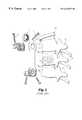
- FIGS. 1 and 2A known osteosynthesis device is depicted in U.S. Pat. No. 5,108,395 to Jean-Marie Laurain, the disclosure of which is incorporated herein by reference.
- This systemis illustrated in FIGS. 1 and 2 of the present application.
- a damaged vertebra V 3includes a destroyed vertebral body C 3 .
- An interior implant 1is provided for bridging between the two intact vertebrae V 2 and V 4 to permit removal of the damaged vertebra V 3 and its adjacent disks D 2 and D 3 .
- the anterior implant 1includes a pair of clamps 2 which are engaged to the intact vertebral bodies by way of a number of spikes 3 .
- the implant 1also includes a plate 6 which is configured to span between the intact vertebrae and is strong enough to support the loads generated in the spinal column at that location.
- Each clamp 2includes a threaded post 12 projecting therefrom which is configured to pass through a corresponding opening 14 at each end of the plate 6 .
- a nut 7is adapted to engage the threaded post 12 to fix the plate 6 to each of the clamps 2 .
- the surface of the clamps 2include serrations 15 which mate with corresponding serrations 16 at each end of the plate 6 , thereby permitting differing angular orientations of the plate relative to each of the clamps.
- An opening 9is provided through the threaded post 12 of the clamps to receive another bone screw 5 for firm fixation of the clamp with the healthy vertebral bodies V 2 and V 4 .
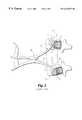
- the notches 18 in each of the clamps 2are configured to receive the tips of a forceps 19 which is used to provide a distraction force between the two vertebrae V 2 and V 4 .
- the forceps 19are used to distract and permit room for placement of a bone graft G.
- the anterior plate 6can be attached to each of the clamps 2 in the manner previously described. Once the plate is in position, the distraction forceps 19 is removed and the nut 7 tightened to form a rigid construct.
- the anterior construct shown in the '395 patent and in FIGS. 1 and 2 of this applicationis one system for providing anterior fixation with the use of autologous or allogenic bone graft material.
- Other implantshave been devised which rely upon an additional element interposed between the adjacent vertebra, in lieu of or in addition to the traditional bone graft material.
- One such deviceis shown in the patent to Harms et al. U.S. Pat. No. 4,820,305, which is sold as the “Harms Cage” by the Biedermann-Motech Company.
- This devicecontemplates a hollow cylindrical mesh which is inserted in the gap between adjacent vertebra, with bone graft material being disposed inside the hollow interior of the mesh.
- the patent to BrantiganU.S. Pat. No. 5,192,327, shows a device similar to the “Harms Cage” which is composed of a number of hollow oval-shaped implants within which bone graft material is disposed.
- European Patent No. 0 179 695 to Kehrshows a rigid inert body having a number of passageways extending between the intact vertebrae into which bone growth material can be implanted.
- the device shown in the Kehr European patentincludes a plate spanning between the vertebrae having holes for receiving bone screws therethrough.
- FIG. 1Another variety of implant devices particularly suited for replacement of vertebral bodies include components of generally solid construction which completely occupy the empty vertebral space. These devices are represented by the patents to Kapp et al., U.S. Pat. No. 4,554,914; Doty, U.S. Pat. No. 4,599,086; Ogilvie et al., U.S. Pat. No. 4,636,217; and Downey, U.S. Pat. No. 5,147,404. Each of these devices is provided with a spike or similar mechanism for engaging the endplates of the intact vertebrae to maintain the implant in position. A similar construction is followed in the U.S. Pat. No. 5,062,850 to MacMillan et al., although this device includes open space between support columns of the axially fixed vertebral body prosthesis.
- the implant devicerequires separate distraction of the intact vertebrae prior to insertion of the device.
- the following patentsshow vertebral prosthesis which include some feature for expansion of the device in situ.
- the Main et al., U.S. Pat. No. 4,932,975, and Barber U.S. Pat. No. 5,236,460show prostheses that telescope through the admission of a hydraulic fluid.
- the patents of Rezaian, U.S. Pat. No. 4,401,112; Wu, U.S. Pat. No. 4,553,273 and Daher, U.S. Pat. No. 4,657,550show devices that expand in situ the manipulation of a threaded component.
- the Rezaian patentshows a turnbuckle construct of this type with the addition of a spiked plate engaged in the opposite intact vertebrae to strengthen the construct.
- each of the above-mentioned vertebral body replacementssuffer from one or more disadvantages. For instance, some of the devices do not provide means for osteosynthesis between the intact vertebrae. These devices lack features that can either permit bone ingrowth or facilitate placement of bone graft between adjacent healthy vertebrae. It is recognized that a more permanent and stable correction of a kyphotic condition occurs with fusion of a bony mass in place of the replaced vertebra. Thus, any vertebral body replacement should accommodate this aspect.
- vertebral prosthesisoffer no means for adjusting the size of the implant to accommodate the specific vertebral anatomy. Further, other of the devices do not contemplate some auxiliary fixation to help provide a stable construct. Each of these needs, and many others, are met by the vertebral body replacement according to the present invention.
- the present inventioncontemplates a vertebral replacement implant and assembly for fixation of the implant in the space left by a removed vertebra between two intact vertebrae.
- the implantincludes a thin-walled cylindrical body sized to occupy a substantial portion of the space between the intact vertebrae.
- the cylindrical bodyis hollow with a plurality of apertures through the wall of the body in communication with the interior, to permit bone ingrowth once the implant is implanted.
- the opposite ends of the cylindrical bodycarries continuous threads, preferably on the outer surface of the body.
- the inventive implantfurther contemplates a pair of endplates having a surface directed against a corresponding one of the intact vertebrae when the prosthesis is implanted.
- the endplateseach include a cylindrical portion extending from the end surface, which portion includes threads for mating with the threaded ends of the cylindrical body.
- the threads of the endplatesare internal to the cylindrical portion.
- the endplatesare themselves hollow to provide communication between the hollow interior of the cylindrical body and the adjacent intact vertebrae.
- the inventioncontemplates the addition of an end cap to the implant to close the end surface of the endplates against the adjacent vertebrae in order to provide additional support for weak vertebrae.
- the end capis formed with a porous material such as porous tantalum provided under the name HEDROCEL® by Implex Corporation.
- the end capmay also include a positioning surface to align the end cap in the endplate opening.
- the end capincludes an anchor projecting into the hollow interior of the implant to resist dislodgment.
- the means for fixingincludes spikes which are integrally attached or threadedly engaged to the endplate.
- the means for fixing the implantincludes blades integrally attached to the endplate.
- the means for fixingincludes apertures in the threaded portion of the endplates which are threaded to accept a set screw.
- a set screwPreferably, two set screws are threaded into two such apertures in the endplates to apply a clamping pressure against the cylindrical body engaged with the endplate.
- the means for fixingcontemplates a crimpable cylindrical portion of the endplates.
- the cylindrical portionincludes an annular ring, dissected by a crimping notch. The application of a crimping force around the annular ring reduces the notch, and thereby reduces the circumference of the cylindrical portion so it is tightly engaged about the cylindrical body threaded therein.
- the longitudinal membermay be a plate or a rod that is fixed in a known manner to the adjacent intact vertebrae.
- the longitudinal membercan be used to assist in the distraction of the intact vertebrae for insertion of the vertebral replacement implant.
- the means for connectingincludes a clamp configured to clamp onto the longitudinal member.
- the clampsupports a screw directed towards the replacement implant when it is interposed between the intact vertebrae.
- the cylindrical body of the implantincludes a number of apertures threaded to receive the connecting screw.
- the clampis preferably slidable along the length of the longitudinal implant to facilitate alignment of the screw with the number of threaded apertures of the cylindrical body.
- the clampincludes a spherical seat, and the screw includes a spherical head to permit varying angular orientations of the screw relative to the longitudinal member.
- the means for connectingincludes an arm extending from a flange of the endplates.
- the free end of the armdefines an opening through which the longitudinal member extends.
- a set screwintersects the opening to provide fixation of the longitudinal member to the arm of the endplates.
- One object of the present inventionis to provide a vertebral body replacement implant configured to support the space left by removal of a damaged or diseased vertebra.
- One objectiveis to provide an implant that can be easily adjusted to vary the overall length of the implant dependent upon the vertebral level into which the implant is interposed.
- a further objective of the inventive implantis to permit this length adjustment yet provide means for fixing the components to prevent disengagement or unthreading.
- a further objectis achieved by the present invention by the provision of means for connecting the vertebral replacement implant to a longitudinal member extending along the length of the spine between the adjacent intact vertebrae.
- the longitudinal membercan be used for distracting the space left by the removed vertebra to facilitate insertion of the replacement implant.
- Yet another objectis to provide an implant that can house bone growth material to facilitate fusion of the instrumented level and promote vascularization between adjacent intact vertebrae and the bone growth material in the implant.
- vertebral body replacement of the present inventionprovides a strong implant to support the spinal loads while awaiting fusion of bone growth material between the intact vertebrae.
- a further benefitis that the implant can be more easily adjusted to accommodate spaces at different vertebral levels.
- the implantprovides a means for fixation to the existing intact vertebrae when the implant is implanted to prevent disengagement.
- FIG. 1is an exploded perspective view of a spinal osteosynthesis implant according to the prior art U.S. Pat. No. 5,108,395.
- FIG. 2is a view showing a portion of the view of FIG. 1 with the addition of an instrument for permitting positioning of a graft between the vertebrae carrying the clamps associated with the prior device of the '395 patent.
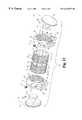
- FIG. 3is an exploded perspective view of a vertebral body replacement assembly in accordance with one embodiment of the present invention.
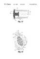
- FIG. 4is an end elevational view of an endplate used in connection with the vertebral body replacement assembly shown in FIG. 3 .
- FIG. 5is a side elevational view of an endplate used with the vertebral body replacement assembly of FIG. 3 .
- FIG. 6is a perspective exploded view showing a component of the clamp assembly used with the vertebral body replacement assembly shown in FIG. 3 .
- FIG. 7is a side elevational view of a vertebral body replacement assembly in accordance with another embodiment of the invention, particularly for use with an elongated rod spanning the vertebral sections.
- FIG. 8is an end elevational view of the vertebral body replacement assembly shown in FIG. 7, with the assembly shown in position on a intact vertebra.
- FIG. 9is a side elevational view of the assembly shown in FIG. 7 as engaged to an elongated rod.
- FIG. 10is a perspective view of the endplate used with the vertebral body replacement assembly shown in FIG. 7 .
- FIG. 11is an end elevational view of one specific endplate used in connection with the vertebral body replacement assembly shown in FIG. 3 in the thoracic spine.
- FIG. 12is a perspective view of a porous end cap used with the endplate shown in FIGS. 10 and 11.
- FIG. 13is a side elevational view of the porous end cap embedded in the implant.
- FIG. 14is a perspective view of the vertebral body replacement endplate with blades in lieu of spikes as shown in FIGS. 3 and 7.
- the assembly 20generally includes a threaded cylindrical body 21 , threaded endplates 22 and end caps 23 .
- a set screw 24is also provided as one embodiment of a means for fixing each of the endplates 22 to a corresponding end of the cylindrical body 21 .
- the set screw 24is a breakable locking screw in which the head of the screw shears off when the tightening torque limit is reached. Such a locking screw is disclosed in co-pending French patent application No. 94 10 377, filed on Aug. 29, 1994.
- the threaded cylindrical body 21is formed from a cylindrical wall 25 which defines a hollow cavity 26 therein.
- the cavityis configured to receive bone osteosynthesis material, which may be in the form of autogenous or allograph material.
- the cylindrical wall 25is provided with a plurality of apertures 28 in communication with the cavity 26 . These apertures provide a path for bone or tissue ingrowth to further enhance the stability of the implant.
- the cylindrical wall 25includes a second plurality of threaded apertures 29 generally in the middle of the implant, which are configured to engage the support assembly 55 as described in more detail herein.
- the opposite ends of the cylindrical wall 25are formed into external threads 32 .
- the threads 32extend from each opposite end over most of the total length of the threaded cylindrical body 21 and are configured to engage the threaded endplates 22 .
- Each endplateincludes a flange 35 , which preferably assumes a shape to cover a substantial load-bearing area of the endplates of the adjacent intact vertebral bodies.
- a cylinder 37is integrally formed with flange 35 to extend toward the threaded cylindrical body 21 when the endplates 22 are placed within the excised vertebral space.
- the cylinder 37 of each endplateincludes a number of threaded openings 39 adapted to receive a set screw 24 therein.
- the cylinder 37 and flange 35 of the endplates 22define a bore 40 therethrough.
- the inside surface of the bore 40is provided with internal threads 41 which are configured to mate with the external threads 32 of the cylindrical body 21 .
- the threads 41extend along at least the entire length of the cylinder 37 and preferably into the flange 35 .
- FIGS. 4 and 5Further details of the endplates 22 can be seen in FIGS. 4 and 5.
- the cylinder 37is integrally formed with the flange 35 to define a lordosis angle 43 .
- This angleis intended to permit use of the vertebral body replacement assembly 20 to replace a damaged vertebra, such as vertebra V 3 shown in FIG. 1, and still maintain the normal lordotic curvature of the spine at that level.
- the end face 36 of the flange 35is provided with vascularization apertures 45 extending through the flange. These apertures 45 are intended to provide an avenue for vascularization of the space between the adjacent vertebrae.
- the end face 36can be provided with four spikes, such as spikes 91 shown in the embodiment of FIG. 7 .
- spikes 120(FIG. 3) can be provided that include a threaded stem 121 to be engaged in threaded apertures 46 defined in end face 36 .
- spikes 91 and 120are replaced by a plurality of blades 130 as shown in FIG. 14 .
- the bladesare preferably integrally attached to end face 36 .
- Each bladeis wedge-shaped with flat surfaces 131 engaged to end face 36 and with a cutting edge 132 projecting outwardly to penetrate an adjacent vertebral surface.
- Blades 130provide for easier insertion of the implant between two adjacent intact vertebrae. Blades 130 also enhance the stability of the interface between the vertebrae by securing the implant to the intact vertebrae when the implant is inserted.
- the end faceis further provided with a mounting slot 47 passing across the flange 35 and spanning along a chord of the internal bore 40 . Within each mounting slot is an aperture 48 passing therethrough.
- the cylinder 37 of the endplate 22is provided with a mounting notch 49 that is aligned with each aperture 48 in the mounting slot 47 .
- This slot 47 , aperture 48 and notch 49are configured to support an end cap 23 , as herein described.
- the end cap 23includes a generally rectangular support bar 50 which is mounted to span across a chord of the flat circular plate 52 of the end cap. At each end of the support bar 50 is an outwardly projecting lug 51 .
- Each lug 51is sized to be received within a corresponding aperture 48 , while the support bar 50 is itself configured to fit within the mounting slot 47 in the flange 35 . Further, each lug 51 slides conveniently into a corresponding mounting notch 49 in the cylinder 37 . In this manner, the end cap 23 is held in position, particularly when the replacement body assembly is disposed between the adjacent intact vertebrae V 2 and V 4 .
- the end cap 23provides additional support for the implant between the adjacent intact vertebrae.
- the end capcan be eliminated if bone growth between the adjacent vertebrae and through the replacement body is preferred.
- the plate 52 of each end cap 23can be perforated to permit bone ingrowth between the vertebral endplates and the bone growth material disposed within the threaded cylindrical body 21 .
- the endplatesare shown solid to provide the maximum load bearing capability for loads along the length of the vertebral column.
- end cap 140is formed of a porous material such as a porous tantalum provided under the name HEDROCEL® by Implex Corporation.
- the HEDROCEL® materialincludes an open cell structure formed by chemical vapor deposition of tantalum onto a reticulated carbon foam substrate.
- the porous end cap 140includes a plurality of internally interconnected interstices, which can permit tissue or bone growth entirely through the end cap.
- a structureis created that is lightweight, strong and porous. The structure also mimics the natural cancellous bone and allows bone ingrowth between the intact vertebrae and the bone growth material disposed within the implant.
- the HEDROCEL® materialalso provides the necessary strength to support vertebral loads.
- Other porous materialmay also be used for end cap 140 provided they have the necessary strength and allow ingrowth between the intact vertebrae and the bone growth material in the implant. The material can preferably be fully integrated into the resulting bone growth.
- End cap 140includes contact surface 141 (FIG. 12) for contacting the intact vertebra when the implant is placed in the space left by one or more removed vertebrae.
- the contact surface 141is slightly convex to conform to the slight concavity of the vertebral endplates.
- End cap 140can further be provided with positioning surface 142 to align the end cap within bore 40 of end face 36 as shown in FIG. 12 .
- the end cap 140can include an anchor 143 projecting from the interior face of the end cap. As shown in FIG. 13, anchor 143 can be embedded in bone growth material 144 to provide stability to the end cap when anchor 143 is placed in bore 40 as the implant is inserted in the space left by one or more removed vertebrae. Anchor 143 also resists dislodgment of the end cap from the device 20 prior to implantation.
- end cap 140includes a stem 145 projecting away from contact surface 141 .
- Anchor 143can be integrally attached to stem 145 .
- stem 145can have a diameter approximately one-half of the diameter of anchor 143 .
- Anchor 143can have a diameter approximately one-half of the diameter of thread cylindrical body 21 . This allows anchor 143 to be inserted into device 20 without total displacement of bone growth material 144 from the interior of end plate 22 .
- Other structures which secure end cap 40 to end plate 22are also contemplated.
- One embodimentcan include a stem that is tapered with the larger end of the stem disposed within the implant.
- Another embodimentmay contemplate a stem with outward protrusions into the bone growth material. These embodiments could be configured to achieve the same desired result as the specific embodiment.
- the threads 32 on the cylindrical replacement bodyare external threads, while the threads 40 in the endplates are internal.
- the cylinder 37 of the endplatescan carry external threads and the cylindrical replacement body carry internal threads in the cavity 26 .
- the inner diameter of the cylindrical bodywould naturally be slightly greater than the outer diameter of the cylinder of the endplates.
- the cylindrical wall forming the implant 21can be relatively thin, when compared against replacement bodies of the prior art.
- the wallis one (1) mm. thick. Since the primary load endured by the implant will be axial compression, rather than bending, a thin-walled cylinder is appropriate and even desirable.
- the implant 21include a large number of apertures 28 , 29 to promote tissue ingrowth and vascularization, thereby enhancing the stability of the construct after fusion has occurred.
- the total area of the plurality of aperturesis at least twenty five percent (25%) of the surface area of the cylindrical body 21 .
- the damaged vertebrasuch as vertebra V 3 shown in FIG. 1
- the clamps 2 of the interior implant 1 shown in FIGS. 1 and 2are engaged to the intact vertebral bodies in the manner shown in FIG. 2 .
- the forceps 19can be used to distract the intact vertebrae to permit implantation of a vertebral body replacement assembly 20 .
- the optimum vertebral heightis determined and the threaded cylindrical body 21 and threaded endplates 22 are fitted together to achieve that proper height. Specifically, each of the end caps can be threaded onto the threaded cylindrical body 21 until the desired height is attained.
- the bottom edge 44 of the flange 35 of each of the endplatesbe generally oriented in the same way between the two threaded endplates 22 . This orientation is important because the replacement assembly 20 will be disposed between the two intact vertebrae, bearing against the endplates of those vertebrae.
- the flanges 35and particularly the end face 36 , assume the shape of the vertebral body against which the endplates bear and are sized to occupy as much area of the intact vertebral body end plate as possible.
- the configuration of the flange 35 shown in FIG. 4is applicable to the thoraco-lumbar vertebrae.
- a smaller, more rounded, configurationcan be provided for implantation at the thoracic level, such as the flange 35 ′ shown in FIG. 11 .
- the flange 35 ′is also shown as including a relief radius 38 to increase the clearance between the flange and the dural space housing the spinal cord. This relief radius 38 is preferably included in all three shapes of the endplate flanges.
- the external threads 32 on the threaded cylindrical body 21are cut in opposite directions so that the endplates can be drawn together or apart by rotating only the cylinder.
- the threads 32 at each of the endsengage the internal threads 41 of each of the end caps 23 in the right direction to draw the end caps together.
- the handedness of the threads 32can be the same at each end so that it is necessary to individually thread each end cap in opposite directions onto the cylindrical body 21 .
- the disadvantage of this arrangementis that it is more difficult to adjust the height of the total assembly 20 while maintaining the proper orientation of each of the lower edges 44 of the end face 36 .
- An advantageis that in situ the assembly is unable to unthread itself.
- the set screws 24are threaded into an appropriate one of the threaded openings 39 in the cylinder 37 of the endplates 22 , in order that the set screw 24 extend into contact with the threaded cylindrical body 21 .
- the set screws 24(which can be the breakable locking screws mentioned above) exert a clamping pressure against the body 21 to hold it in place.
- the set screws 24provide a means for fixing the components together and prevent rotation of the cylindrical body 21 with respect to either of the endplates 22 .
- two set screwsare used at each endplate 23 to firmly fix the associated ends of the threaded cylindrical body 21 .
- the apertures 28 in the threaded bodyhave a smaller diameter than the set screws 24 .
- bone graft materialcan then be inserted into the bore 40 of the endplates and cavity 26 of the cylindrical body 21 .
- the endplates 23are placed in position with the lugs 51 extending through apertures 48 , and with support bar 50 passing through mounting slot 47 in each endplate.
- the replacement assembly 20can then be disposed between the distracted vertebrae V 2 and V 4 .
- a support assembly 55may be provided.
- this support assembly 55is configured to mate with the clamps 2 used with the anterior implant system of the prior art shown in FIGS. 1 and 2.
- the support assembly 55can also be used with other anterior plates, such as the Z-PLATE ATL* sold by Danek Medical, Inc., or rod systems such as the CD Hopf System of Sofamor, S.N.C.
- the support assemblyincludes a stabilization plate 57 , which can be configured substantially similar to the plate 6 shown in FIG. 1, including the serrations on the bottom face of the ends of the plate.
- Means for connecting the vertebral replacement body assembly 20 to the plate 57includes a clamp assembly 59 is provided which firmly grips the plate 57 to support a locking screw 69 .
- the clamp assembly 59includes a pair of clamp halves 60 which are preferably in the shape of a C to grip and support the plate 57 .
- Each of the clamp halves 60include an aperture (not shown) which receives a threaded rod 63 of an adjustment plate 62 .
- a nut 64is threaded on the rod 63 to draw the clamp halves 60 together about the stabilization plate 57 .
- the adjustment plate 62includes the threaded rod 63 extending from a face 65 of the plate 62 .
- the plate 62also includes an aperture 67 therethrough having a spherical seat surface 68 into which a corresponding spherical head 70 of the locking screw 69 is received.
- the locking screw 69includes a hex recess 71 in its head to accept a driving tool.
- the locking screw 69also includes a threaded shank 73 which is adapted to engage one of the threaded apertures 29 in the threaded cylindrical body 21 .
- a guide nub 75is provided having a smaller diameter than the threaded shank 73 .
- the locking screw 69preferably includes smooth shank 74 between the head 70 of the screw and the threaded shank 73 .
- the clamp halves 60can be tentatively attached but not clamped to the stabilization plate 57 .
- the stabilization plate 57can then be engaged to the clamps 2 in each of the intact vertebral bodies and fixed in place by a corresponding nut, such as nut 7 shown in FIG. 1 .
- the distraction forceps 19can be removed so that the full load of the spinal column can be borne by the replacement assembly 20 .
- the clamp halves 60can be adjusted along the length of the plate 57 so that the locking screw 69 is aligned with an appropriate one of the threaded apertures 29 in the threaded cylindrical body 21 .
- the spherical contact between the head 70 of the locking screw 69 and the spherical seat 68 of the adjustment plate 62allows the locking screw to assume whatever angle is necessary to engage a threaded aperture 29 .
- the locking screw 69can then be easily threaded into one of the apertures 29 until it is locked between the adjustment plate 62 and the threaded cylindrical body 21 .
- the clamp halves 60can be fully clamped onto the plate 57 by tightening the nut 64 on the threaded rod 63 .
- a vertebral body replacement assembly 80is configured for connection to an elongated distraction or compression rod.
- the assembly 80includes opposite endplates 83 which are configured to threadedly engage a cylindrical body 21 .
- This cylindrical body 21is substantially identical in all respects to the cylindrical body 21 described with respect to FIG. 3 ).
- the endplates 83include a flange 85 and a cylinder 87 projecting therefrom.
- the cylinder 87includes a threaded bore 88 which is threaded to accept the external threads 32 of the cylindrical body 21 .
- the endplate 83includes a plurality of vascularization apertures 89 formed through the flange 85 .
- the end face 86 of the flange 85includes a number of spikes 91 or blades 130 projecting therefrom. The spikes or blades are configured to penetrate the end plate of the adjacent vertebral bodies to help maintain the position of the implant in situ.
- the endplates 83include an arm 94 projecting from the flange 85 , which is a component of a means for connecting the implant to a longitudinal member, such as rod 105 .
- a rod bore 95is defined adjacent the free end 94 a of the arm 94 , with a set screw bore 96 intersecting the rod bore 95 from the free end of the arm 94 .
- a set screw 98is provided which is engaged within the set screw bore 96 to clamp a rod passing therethrough.
- FIGS. 8 and 9The manner of using the replacement assembly 80 in this embodiment is shown in FIGS. 8 and 9.
- the endplates 83are engaged in the appropriate vertebrae by way of spikes 91 or blades 130 .
- the platesare configured to define an angle 115 to correspond to the proper spinal anatomy at the particular vertebral level.
- a distraction plate 107is mounted into each of the intact vertebrae by way of bone screw 108 .
- the plate 107includes a collar 109 integrally formed thereon through which a distraction rod 105 passes.
- the distraction rodalso extends through each of the rod bores 95 in the arms 94 of the endplates 83 .
- the set screws 98fix the endplates in position. Distraction of the adjacent vertebrae can be achieved by an appropriately formed instrument that can engage the collars 109 of each of the distraction plates 107 mounted into the respective vertebrae.
- a set screw(not shown) can be provided to fix the rod 105 within each collar 109 .
- the endplates 83and particularly the cylinder 87 of the endplates, is provided with a means for fixing in the form of a crimping channel 100 around the diameter of the cylinder.
- a crimping notch 101is provided in the channel 100 .
- this crimping notchis a gap in the outer circumference of the channel 100 .
- This crimping notchprovides a gap which can be closed by an appropriate crimping tool gripping the entire circumference of the crimping channel 100 .
Landscapes
- Health & Medical Sciences (AREA)
- Orthopedic Medicine & Surgery (AREA)
- Cardiology (AREA)
- Oral & Maxillofacial Surgery (AREA)
- Transplantation (AREA)
- Engineering & Computer Science (AREA)
- Biomedical Technology (AREA)
- Heart & Thoracic Surgery (AREA)
- Vascular Medicine (AREA)
- Life Sciences & Earth Sciences (AREA)
- Animal Behavior & Ethology (AREA)
- General Health & Medical Sciences (AREA)
- Public Health (AREA)
- Veterinary Medicine (AREA)
- Prostheses (AREA)
Abstract
Description
Claims (23)
Priority Applications (22)
| Application Number | Priority Date | Filing Date | Title |
|---|---|---|---|
| CA002207336ACA2207336A1 (en) | 1994-12-09 | 1995-12-01 | Adjustable vertebral body replacement |
| ES04025962TES2259169T3 (en) | 1994-12-09 | 1995-12-01 | REPLACEMENT OF ADJUSTABLE VERTEBRAL BODY. |
| JP51767296AJP3732228B2 (en) | 1994-12-09 | 1995-12-01 | Adjustable vertebral body replacement |
| DE69534978TDE69534978T2 (en) | 1994-12-09 | 1995-12-01 | Adjustable vertebral body replacement |
| AT04025962TATE324846T1 (en) | 1994-12-09 | 1995-12-01 | ADJUSTABLE VERTEBRATE REPLACEMENT |
| ES95942527TES2238684T3 (en) | 1994-12-09 | 1995-12-01 | SUBSTITUTION OF ADJUSTABLE VERTEBRAL BODY. |
| PCT/US1995/015654WO1996017564A1 (en) | 1994-12-09 | 1995-12-01 | Adjustable vertebral body replacement |
| EP04025962AEP1512385B1 (en) | 1994-12-09 | 1995-12-01 | Adjustable vertebral body replacement |
| EP95942527AEP0797418B1 (en) | 1994-12-09 | 1995-12-01 | Adjustable vertebral body replacement |
| DE69534042TDE69534042T2 (en) | 1994-12-09 | 1995-12-01 | ADJUSTABLE ANGLE BODY SET |
| AT95942527TATE289786T1 (en) | 1994-12-09 | 1995-12-01 | ADJUSTABLE VERTEBRATE REPLACEMENT |
| AU43725/96AAU4372596A (en) | 1994-12-09 | 1995-12-01 | Adjustable vertebral body replacement |
| ZA9510445AZA9510445B (en) | 1994-12-09 | 1995-12-08 | Adjustable vertebral body replacement |
| US08/647,272US5702453A (en) | 1994-12-09 | 1996-05-13 | Adjustable vertebral body replacement |
| US09/073,081US6344057B1 (en) | 1994-11-22 | 1998-05-05 | Adjustable vertebral body replacement |
| DE69916261TDE69916261T2 (en) | 1994-12-09 | 1999-04-29 | ADJUSTABLE ANGLE BODY SET |
| PT99921520TPT1077659E (en) | 1994-12-09 | 1999-04-29 | ADJUSTABLE REPLACEMENT DEVICE FOR VERTEBRATIC BODIES |
| EP99921520AEP1077659B1 (en) | 1994-12-09 | 1999-04-29 | Adjustable vertebral body replacement |
| ES99921520TES2217752T3 (en) | 1994-12-09 | 1999-04-29 | ADJUSTABLE DEVICE FOR VERTEBRAL BODY REPLACEMENT. |
| AT99921520TATE263525T1 (en) | 1994-12-09 | 1999-04-29 | ADJUSTABLE VERTEBRATE REPLACEMENT |
| PCT/US1999/009271WO1999056675A1 (en) | 1994-12-09 | 1999-04-29 | Adjustable vertebral body replacement |
| AU38711/99AAU3871199A (en) | 1994-12-09 | 1999-04-29 | Adjustable vertebral body replacement |
Applications Claiming Priority (4)
| Application Number | Priority Date | Filing Date | Title |
|---|---|---|---|
| US08/343,566US5453454A (en) | 1992-06-04 | 1993-05-26 | Production of foam boards of high compressive strength from styrene polymers |
| US08/647,272US5702453A (en) | 1994-12-09 | 1996-05-13 | Adjustable vertebral body replacement |
| US08/814,115US5776198A (en) | 1994-12-09 | 1997-03-10 | Adjustable vertebral body replacement |
| US09/073,081US6344057B1 (en) | 1994-11-22 | 1998-05-05 | Adjustable vertebral body replacement |
Related Parent Applications (1)
| Application Number | Title | Priority Date | Filing Date |
|---|---|---|---|
| US08/814,115Continuation-In-PartUS5776198A (en) | 1994-11-22 | 1997-03-10 | Adjustable vertebral body replacement |
Publications (1)
| Publication Number | Publication Date |
|---|---|
| US6344057B1true US6344057B1 (en) | 2002-02-05 |
Family
ID=27407569
Family Applications (1)
| Application Number | Title | Priority Date | Filing Date |
|---|---|---|---|
| US09/073,081Expired - Fee RelatedUS6344057B1 (en) | 1994-11-22 | 1998-05-05 | Adjustable vertebral body replacement |
Country Status (1)
| Country | Link |
|---|---|
| US (1) | US6344057B1 (en) |
Cited By (189)
| Publication number | Priority date | Publication date | Assignee | Title |
|---|---|---|---|---|
| US20020123807A1 (en)* | 1999-10-20 | 2002-09-05 | Cauthen Joseph C. | Spinal disc annulus reconstruction method and spinal disc annulus stent |
| US20020128712A1 (en)* | 2001-03-09 | 2002-09-12 | Michelson Gary K. | Expansion constraining member adapted for use with an expandable interbody spinal fusion implant |
| US20030153976A1 (en)* | 1999-10-20 | 2003-08-14 | Cauthen Joseph C. | Spinal disc annulus reconstruction method and spinal disc annulus stent |
| US20030174929A1 (en)* | 2002-03-15 | 2003-09-18 | Rodgers Murray Steven | Self-shadowing MEM structures |
| US20030181983A1 (en)* | 1999-10-20 | 2003-09-25 | Cauthen Joseph C. | Spinal disc annulus reconstruction method and spinal disc annulus stent |
| US20030191535A1 (en)* | 2002-04-05 | 2003-10-09 | Michael Castro | Apparatus for fusing adjacent bone structures |
| US20040010316A1 (en)* | 2002-03-30 | 2004-01-15 | Lytton William | Intervertebral device and method of use |
| US20040059271A1 (en)* | 2002-09-23 | 2004-03-25 | Sdgi Holdings, Inc. | Expansion tool for adjustable spinal implant |
| US6719796B2 (en)* | 1999-07-26 | 2004-04-13 | Advanced Prosthetic Technologies, Inc. | Spinal surgical prosthesis |
| US20040122518A1 (en)* | 2002-12-19 | 2004-06-24 | Rhoda William S. | Intervertebral implant |
| US20040172020A1 (en)* | 2001-04-06 | 2004-09-02 | Jacques Beaurain | Spinal osteosynthesis device and preparation method |
| US20040176842A1 (en)* | 1998-06-17 | 2004-09-09 | Howmedica Osteonics Corp. | Artificial intervertebral disc |
| US20040243240A1 (en)* | 2001-05-04 | 2004-12-02 | Jacques Beaurain | Intervertebral disc prosthesis and fitting tools |
| US20040254577A1 (en)* | 2001-10-18 | 2004-12-16 | Joel Delecrin | Progressive approach osteosynthesis device and preassembly method |
| US20050010215A1 (en)* | 2001-10-18 | 2005-01-13 | Joel Delecrin | Plate for osteosynthesis device and preassembling method |
| US20050027362A1 (en)* | 1999-02-26 | 2005-02-03 | Williams Lytton A. | Method and apparatus for intervertebral implant anchorage |
| US20050065611A1 (en)* | 2001-11-06 | 2005-03-24 | Jean Huppert | Osseous achoring device for a prosthesis |
| US20050070911A1 (en)* | 2003-09-29 | 2005-03-31 | Scimed Life Systems, Inc. | Apparatus and methods for reducing compression bone fractures using high strength ribbed members |
| US20050085910A1 (en)* | 2003-10-16 | 2005-04-21 | Sweeney Patrick J. | Vertebral prosthesis |
| US20050107788A1 (en)* | 2001-12-12 | 2005-05-19 | Jacques Beaurain | Implant for osseous anchoring with polyaxial head |
| US20050125986A1 (en)* | 2003-12-16 | 2005-06-16 | Stryker Spine | Apparatus and method for cutting spinal implants |
| US20050187634A1 (en)* | 2003-03-20 | 2005-08-25 | Berry Bret M. | Height adjustable vertebral body and disc space replacement devices |
| US20050197706A1 (en)* | 2004-02-04 | 2005-09-08 | Ldr Medical, Inc. | Intervertebral disc prosthesis |
| US20060015184A1 (en)* | 2004-01-30 | 2006-01-19 | John Winterbottom | Stacking implants for spinal fusion |
| US20060064167A1 (en)* | 2004-09-23 | 2006-03-23 | Cervitech, Inc. | Prosthesis for partial replacement of a vertebral body |
| US20060074490A1 (en)* | 2004-10-01 | 2006-04-06 | Sweeney Patrick J | Vertebral prosthesis and spinal fixation system |
| US20060136063A1 (en)* | 2004-12-22 | 2006-06-22 | Ldr Medical | Intervertebral disc prosthesis |
| US20060167553A1 (en)* | 1999-10-20 | 2006-07-27 | Anulex Technologies, Inc. | Spinal disc annulus reconstruction method and deformable spinal disc annulus stent |
| US20060195095A1 (en)* | 2003-03-24 | 2006-08-31 | Theken Surgical, Llc | Spinal implant adjustment |
| US20060241762A1 (en)* | 2003-12-11 | 2006-10-26 | Deltacor Gmbh | Height-adjustable spinal implant and operating instrument for the implant |
| US20060241770A1 (en)* | 2005-04-21 | 2006-10-26 | Rhoda William S | Expandable vertebral prosthesis |
| US20060293755A1 (en)* | 2005-05-19 | 2006-12-28 | Aesculap Ag & Co.Kg | Vertebral body replacement implant |
| US20070016217A1 (en)* | 2005-06-29 | 2007-01-18 | Ldr Medical | Instrumentation and methods for inserting an intervertebral disc prosthesis |
| US20070028710A1 (en)* | 2003-05-14 | 2007-02-08 | Kilian Kraus | Height-adjustable implant to be inserted between vertebral bodies and corresponding handling tool |
| US20070061013A1 (en)* | 1999-10-20 | 2007-03-15 | Cauthen Iii Joseph C | Methods and devices for spinal disc annulus reconstruction and repair |
| US20070073311A1 (en)* | 2005-09-26 | 2007-03-29 | Williams Lytton A | System and method for intervertebral implant delivery and removal |
| US20070100348A1 (en)* | 1999-10-20 | 2007-05-03 | Cauthen Joseph C Iii | Apparatus and methods for the treatment of the intervertebral disc |
| US20070106316A1 (en)* | 2005-10-10 | 2007-05-10 | University Of South Florida | Dural Knife with Foot Plate |
| US20070129805A1 (en)* | 2005-12-01 | 2007-06-07 | Braddock Danny H Jr | End device for a vertebral implant |
| US20070156245A1 (en)* | 1999-10-20 | 2007-07-05 | Cauthen Joseph C Iii | Method and apparatus for the treatment of the intervertebral disc annulus |
| US20070162130A1 (en)* | 2005-11-30 | 2007-07-12 | Ralph Rashbaum | Intervertebral disc prosthesis and instrumentation for insertion of the prosthesis between the vertebrae |
| US20070168039A1 (en)* | 2006-01-13 | 2007-07-19 | Sdgi Holdings, Inc. | Materials, devices and methods for treating multiple spinal regions including vertebral body and endplate regions |
| US20070173821A1 (en)* | 2006-01-13 | 2007-07-26 | Sdgi Holdings, Inc. | Materials, devices, and methods for treating multiple spinal regions including the posterior and spinous process regions |
| US20070173820A1 (en)* | 2006-01-13 | 2007-07-26 | Sdgi Holdings, Inc. | Materials, devices, and methods for treating multiple spinal regions including the anterior region |
| US20070185497A1 (en)* | 1999-10-20 | 2007-08-09 | Cauthen Joseph C | Method and apparatus for the treatment of the intervertebral disc annulus |
| US20070213718A1 (en)* | 2006-02-14 | 2007-09-13 | Sdgi Holdings, Inc. | Treatment of the vertebral column |
| US20070213717A1 (en)* | 2006-02-14 | 2007-09-13 | Sdgi Holdings, Inc. | Biological fusion in the vertebral column |
| US20070213823A1 (en)* | 2006-02-14 | 2007-09-13 | Sdgi Holdings, Inc. | Treatment of the vertebral column |
| US20070227547A1 (en)* | 2006-02-14 | 2007-10-04 | Sdgi Holdings, Inc. | Treatment of the vertebral column |
| US7285134B2 (en) | 2003-10-22 | 2007-10-23 | Warsaw Orthopedic, Inc. | Vertebral body replacement implant |
| US20070250171A1 (en)* | 2006-04-24 | 2007-10-25 | Sdgi Holdings, Inc. | Expandable intervertebral devices and methods of use |
| US20070255408A1 (en)* | 2006-04-27 | 2007-11-01 | Sdgi Holdings, Inc. | Stabilized, adjustable expandable implant and method |
| US20070255413A1 (en)* | 2006-04-27 | 2007-11-01 | Sdgi Holdings, Inc. | Expandable intervertebral spacers and methods of use |
| US20070255407A1 (en)* | 2006-04-27 | 2007-11-01 | Sdgi Holdings, Inc. | Self-contained expandable implant and method |
| US20070255409A1 (en)* | 2006-04-27 | 2007-11-01 | Sdgi Holdings, Inc. | Expandable implant, instrument, and method |
| US20070255415A1 (en)* | 2006-05-01 | 2007-11-01 | Sdgi Holdings, Inc. | Expandable intervertebral spacers and methods of use |
| US20070255410A1 (en)* | 2006-04-27 | 2007-11-01 | Sdgi Holdings, Inc. | Centrally driven expandable implant and method |
| US20070270960A1 (en)* | 2006-04-24 | 2007-11-22 | Sdgi Holdings, Inc. | Extendable anchor in a vertebral implant and methods of use |
| US20070270964A1 (en)* | 2006-04-27 | 2007-11-22 | Sdgi Holdings, Inc. | Expandable vertebral implant and methods of use |
| US20080009946A1 (en)* | 2006-06-20 | 2008-01-10 | Stephane Douget | Distractible intervertebral implant |
| US7320708B1 (en) | 2002-11-13 | 2008-01-22 | Sdgi Holdings, Inc. | Cervical interbody device |
| US20080021555A1 (en)* | 2006-07-19 | 2008-01-24 | John White | Expandable vertebral body implants and methods of use |
| US20080058808A1 (en)* | 2006-06-14 | 2008-03-06 | Spartek Medical, Inc. | Implant system and method to treat degenerative disorders of the spine |
| US20080103601A1 (en)* | 1999-07-26 | 2008-05-01 | Ladislau Biro | Corpectomy vertebral body replacement implant system |
| US20080114457A1 (en)* | 2006-11-14 | 2008-05-15 | Warsaw Orthopedic, Inc. | Methods and devices for connecting implants and devices |
| US20080161926A1 (en)* | 2006-10-16 | 2008-07-03 | Warsaw Orthopedic, Inc. | Implants with Helical Supports and Methods of Use for Spacing Vertebral Members |
| US20080167726A1 (en)* | 2007-01-08 | 2008-07-10 | Warsaw Orthopedic, Inc. | Expandable containment devices and methods |
| US20080167720A1 (en)* | 2007-01-08 | 2008-07-10 | Warsaw Orthopedic, Inc. | Expandable vertebral body replacement device |
| US20080200984A1 (en)* | 2007-02-16 | 2008-08-21 | Ldr Medical | Intervertebral Disc Prosthesis Insertion Assemblies |
| US20080306516A1 (en)* | 2007-06-05 | 2008-12-11 | Spartek Medical, Inc. | Multi-dimensional horizontal rod for a dynamic stabilization and motion preservation spinal implantation system and method |
| US20080306545A1 (en)* | 2007-06-05 | 2008-12-11 | Spartek Medical, Inc. | Deflection rod system for a dynamic stabilization and motion preservation spinal implantation system and method |
| US7494508B2 (en) | 2004-04-28 | 2009-02-24 | Ldr Medical | Intervertebral disc prosthesis |
| US20090105832A1 (en)* | 2007-06-08 | 2009-04-23 | Ldr Medical | Intersomatic cage, intervertebral prosthesis, anchoring device and implantation instruments |
| US20090112324A1 (en)* | 2007-10-30 | 2009-04-30 | Biospine, Llc | Vertebral body replacement device and method for use to maintain a space between two vertebral bodies within a spine |
| US20090112325A1 (en)* | 2007-10-30 | 2009-04-30 | Biospine, Llc | Footplate member and a method for use in a vertebral body replacement device |
| US20090118834A1 (en)* | 2007-04-01 | 2009-05-07 | Spinal Kinetics, Inc. | Expandable Prosthetic Intervertebral Discs That Are Implantable By Minimally Invasive Surgical Techniques |
| US7544208B1 (en) | 2004-05-03 | 2009-06-09 | Theken Spine, Llc | Adjustable corpectomy apparatus |
| US20090149955A1 (en)* | 2004-11-20 | 2009-06-11 | Dajue Wang | Spinal prostheses |
| US20090164017A1 (en)* | 2007-12-19 | 2009-06-25 | Robert Sommerich | Expandable Corpectomy Spinal Fusion Cage |
| US20090164018A1 (en)* | 2007-12-19 | 2009-06-25 | Robert Sommerich | Instruments For Expandable Corpectomy Spinal Fusion Cage |
| US20090187248A1 (en)* | 2008-01-18 | 2009-07-23 | Warsaw Orthopedic, Inc. | Lordotic expanding vertebral body spacer |
| US20090204219A1 (en)* | 2002-11-05 | 2009-08-13 | Jacques Beaurain | Intervertebral Disc Prosthesis |
| US20090222100A1 (en)* | 2008-02-28 | 2009-09-03 | Stryker Spine | Tool for implanting expandable intervertebral implant |
| US20100030273A1 (en)* | 2008-02-26 | 2010-02-04 | Spartek Medical, Inc. | Versatile polyaxial connector assembly and method for dynamic stabilization of the spine |
| US20100030271A1 (en)* | 2008-02-26 | 2010-02-04 | Spartek Medical, Inc. | Modular in-line deflection rod and bone anchor system and method for dynamic stabilization of the spine |
| US20100030279A1 (en)* | 2008-02-26 | 2010-02-04 | Spartek Medical, Inc. | Load-sharing bone anchor having a deflectable post and axial spring and method for dynamic stabilization of the spine |
| US20100030274A1 (en)* | 2007-06-05 | 2010-02-04 | Spartek Medical, Inc. | Dynamic spinal rod and method for dynamic stabilization of the spine |
| US20100030267A1 (en)* | 2007-06-05 | 2010-02-04 | Spartek Medical, Inc. | Surgical tool and method for implantation of a dynamic bone anchor |
| US20100030224A1 (en)* | 2008-02-26 | 2010-02-04 | Spartek Medical, Inc. | Surgical tool and method for connecting a dynamic bone anchor and dynamic vertical rod |
| US20100030270A1 (en)* | 2007-06-05 | 2010-02-04 | Spartek Medical, Inc. | Dynamic spinal rod assembly and method for dynamic stabilization of the spine |
| US20100036435A1 (en)* | 2008-02-26 | 2010-02-11 | Spartek Medical, Inc. | Load-sharing bone anchor having a deflectable post and method for dynamic stabilization of the spine |
| US20100036437A1 (en)* | 2008-02-26 | 2010-02-11 | Spartek Medical, Inc. | Load-sharing bone anchor having a deflectable post with a compliant ring and method for stabilization of the spine |
| US20100036436A1 (en)* | 2008-02-26 | 2010-02-11 | Spartek Medical, Inc. | Load-sharing bone anchor having a durable compliant member and method for dynamic stabilization of the spine |
| US20100100100A1 (en)* | 2008-10-16 | 2010-04-22 | Daniel Refai | Surgical instrument and method of use for inserting an implant between two bones |
| US20100131066A1 (en)* | 2004-09-23 | 2010-05-27 | Cervitech, Inc. | Prosthesis for bridging a vertebral body |
| US20100168795A1 (en)* | 2008-02-26 | 2010-07-01 | Spartek Medical, Inc. | Load-sharing bone anchor having a natural center of rotation and method for dynamic stabilization of the spine |
| US20100179658A1 (en)* | 2007-09-24 | 2010-07-15 | University Of South Florida | Vertebral Body Cage |
| US20100179655A1 (en)* | 2009-01-12 | 2010-07-15 | Noah Hansell | Expandable Vertebral Prosthesis |
| US20100211119A1 (en)* | 2009-02-19 | 2010-08-19 | Daniel Refai | Multi-functional surgical instrument and method of use for inserting an implant between two bones |
| US7799081B2 (en) | 2004-09-14 | 2010-09-21 | Aeolin, Llc | System and method for spinal fusion |
| US20100241231A1 (en)* | 2009-02-20 | 2010-09-23 | Marino James F | Intervertebral fixation device |
| US20100280616A1 (en)* | 2009-04-29 | 2010-11-04 | William Frasier | Minimally invasive corpectomy cage and instrument |
| US7842088B2 (en) | 2005-09-23 | 2010-11-30 | Ldr Medical | Intervertebral disc prosthesis |
| US20100324686A1 (en)* | 2009-06-17 | 2010-12-23 | Gerner Leonie | Implant |
| US7906132B2 (en) | 2002-09-17 | 2011-03-15 | Biocer-Entwickslung GmbH | Anti-infectious, biocompatible titanium coating for implants, and method for the production thereof |
| US7935147B2 (en) | 1999-10-20 | 2011-05-03 | Anulex Technologies, Inc. | Method and apparatus for enhanced delivery of treatment device to the intervertebral disc annulus |
| US20110118783A1 (en)* | 2009-11-16 | 2011-05-19 | Spartek Medical, Inc. | Load-sharing bone anchor having a flexible post and method for dynamic stabilization of the spine |
| US7963978B2 (en) | 2007-06-05 | 2011-06-21 | Spartek Medical, Inc. | Method for implanting a deflection rod system and customizing the deflection rod system for a particular patient need for dynamic stabilization and motion preservation spinal implantation system |
| US8021396B2 (en) | 2007-06-05 | 2011-09-20 | Spartek Medical, Inc. | Configurable dynamic spinal rod and method for dynamic stabilization of the spine |
| WO2011130329A1 (en)* | 2010-04-12 | 2011-10-20 | Globus Medical, Inc. | Expandable vertebral implant |
| US8057515B2 (en) | 2008-02-26 | 2011-11-15 | Spartek Medical, Inc. | Load-sharing anchor having a deflectable post and centering spring and method for dynamic stabilization of the spine |
| US8062366B2 (en) | 2007-01-08 | 2011-11-22 | Warsaw Orthopedic, Inc. | Ratcheting expandable corpectomy/vertebrectomy cage |
| US8097024B2 (en) | 2008-02-26 | 2012-01-17 | Spartek Medical, Inc. | Load-sharing bone anchor having a deflectable post and method for stabilization of the spine |
| US8114134B2 (en) | 2007-06-05 | 2012-02-14 | Spartek Medical, Inc. | Spinal prosthesis having a three bar linkage for motion preservation and dynamic stabilization of the spine |
| US8128698B2 (en) | 1999-10-20 | 2012-03-06 | Anulex Technologies, Inc. | Method and apparatus for the treatment of the intervertebral disc annulus |
| US20120083882A1 (en)* | 2010-10-01 | 2012-04-05 | Metal Industries Research&Development Centre | Spinal implant structure and method for manufacturing the same |
| US8163022B2 (en) | 2008-10-14 | 2012-04-24 | Anulex Technologies, Inc. | Method and apparatus for the treatment of the intervertebral disc annulus |
| US20120116457A1 (en)* | 2010-11-06 | 2012-05-10 | Limited Liability Company; | Stabilizer for assisting stabilization of a spinal implant and method of using the stabilizer |
| US8257397B2 (en) | 2009-12-02 | 2012-09-04 | Spartek Medical, Inc. | Low profile spinal prosthesis incorporating a bone anchor having a deflectable post and a compound spinal rod |
| US20120239153A1 (en)* | 2005-05-06 | 2012-09-20 | Titan Spine, Llc. | Endplate-preserving spinal implant having a raised expulsion-resistant edge |
| US20120239154A1 (en)* | 2005-05-06 | 2012-09-20 | Titan Spine, Llc | Endplate-preserving spinal implant with an integration plate having durable connectors |
| US20120245694A1 (en)* | 2005-05-06 | 2012-09-27 | Titan Spine, Llc | Endplate-preserving spinal implant with an integration plate having durable connectors |
| US8282683B2 (en) | 2010-04-12 | 2012-10-09 | Globus Medical, Inc. | Expandable vertebral implant |
| US20120277876A1 (en)* | 2005-05-06 | 2012-11-01 | Titan Spine, Llc | Spinal implant having a passage for enhancing contact between bone graft material and cortical endplate bone |
| US8328871B2 (en) | 2006-11-09 | 2012-12-11 | Warsaw Orthopedic, Inc. | Expanding vertebral body implant |
| US8337536B2 (en) | 2008-02-26 | 2012-12-25 | Spartek Medical, Inc. | Load-sharing bone anchor having a deflectable post with a compliant ring and method for stabilization of the spine |
| US8377140B2 (en) | 2011-01-12 | 2013-02-19 | Ebi, Llc | Expandable spinal implant device |
| US8430916B1 (en) | 2012-02-07 | 2013-04-30 | Spartek Medical, Inc. | Spinal rod connectors, methods of use, and spinal prosthesis incorporating spinal rod connectors |
| US8435302B2 (en) | 2005-05-06 | 2013-05-07 | Titan Spine, Llc | Instruments and interbody spinal implants enhancing disc space distraction |
| US8460319B2 (en) | 2010-01-11 | 2013-06-11 | Anulex Technologies, Inc. | Intervertebral disc annulus repair system and method |
| US8496710B2 (en) | 2005-05-06 | 2013-07-30 | Titan Spine, Llc | Interbody spinal implant having a roughened surface topography |
| CN103239282A (en)* | 2012-02-10 | 2013-08-14 | 北京爱康宜诚医疗器材股份有限公司 | Vertebral body union internal fixation system |
| US8518085B2 (en) | 2010-06-10 | 2013-08-27 | Spartek Medical, Inc. | Adaptive spinal rod and methods for stabilization of the spine |
| US8545568B2 (en) | 2005-05-06 | 2013-10-01 | Titan Spine, Llc | Method of using instruments and interbody spinal implants to enhance distraction |
| US20130268079A1 (en)* | 2010-11-06 | 2013-10-10 | Igip, Llc | Stabilizer For Assisting Stabilization Of A Spinal Implant |
| US8562684B2 (en) | 2005-05-06 | 2013-10-22 | Titan Spine, Llc | Endplate-preserving spinal implant with an integration plate having a roughened surface topography |
| US8562685B2 (en) | 2005-05-06 | 2013-10-22 | Titan Spine, Llc | Spinal implant and integration plate for optimizing vertebral endplate contact load-bearing edges |
| US8591590B2 (en) | 2005-05-06 | 2013-11-26 | Titan Spine, Llc | Spinal implant having a transverse aperture |
| US8591587B2 (en) | 2007-10-30 | 2013-11-26 | Aesculap Implant Systems, Llc | Vertebral body replacement device and method for use to maintain a space between two vertebral bodies within a spine |
| US8591585B2 (en) | 2010-04-12 | 2013-11-26 | Globus Medical, Inc. | Expandable vertebral implant |
| US8617248B2 (en) | 2005-05-06 | 2013-12-31 | Titan Spine, Llc | Spinal implant having variable ratios of the integration surface area to the axial passage area |
| US8740980B2 (en) | 2011-01-27 | 2014-06-03 | Warsaw Orthopedic, Inc. | Expandable medical implant |
| US8758443B2 (en) | 2005-05-06 | 2014-06-24 | Titan Spine, Llc | Implants with integration surfaces having regular repeating surface patterns |
| US8758442B2 (en) | 2005-05-06 | 2014-06-24 | Titan Spine, Llc | Composite implants having integration surfaces composed of a regular repeating pattern |
| US8814939B2 (en) | 2005-05-06 | 2014-08-26 | Titan Spine, Llc | Implants having three distinct surfaces |
| US8845691B2 (en) | 2003-09-01 | 2014-09-30 | Ldr Medical | Osseous anchoring implant with a polyaxial head and method for installing the implant |
| US8870880B2 (en) | 2010-04-12 | 2014-10-28 | Globus Medical, Inc. | Angling inserter tool for expandable vertebral implant |
| US8992622B2 (en) | 2005-05-06 | 2015-03-31 | Titan Spine, Llc | Interbody spinal implant having a roughened surface topography |
| US8992619B2 (en) | 2011-11-01 | 2015-03-31 | Titan Spine, Llc | Microstructured implant surfaces |
| US8992617B2 (en) | 2007-03-13 | 2015-03-31 | DePuy Synthes Products, LLC | Adjustable intervertebral implant |
| US9125756B2 (en) | 2005-05-06 | 2015-09-08 | Titan Spine, Llc | Processes for producing regular repeating patterns on surfaces of interbody devices |
| US9138217B2 (en) | 2009-11-11 | 2015-09-22 | Nu Vasive, Inc. | Surgical access system and related methods |
| US9168147B2 (en) | 2005-05-06 | 2015-10-27 | Titan Spine, Llc | Self-deploying locking screw retention device |
| US9173745B2 (en) | 2009-12-31 | 2015-11-03 | Ldr Medical | Instruments and methods for removing fixation devices from intervertebral implants |
| US9211193B2 (en) | 2013-08-30 | 2015-12-15 | Aesculap Implant Systems, Llc | Prosthesis, system and method |
| US9271842B2 (en) | 2010-04-12 | 2016-03-01 | Globus Medical, Inc. | Expandable trial assembly for expandable vertebral implant |
| US9320610B2 (en) | 2011-08-16 | 2016-04-26 | Stryker European Holdings I, Llc | Expandable implant |
| US9387090B2 (en) | 2009-03-12 | 2016-07-12 | Nuvasive, Inc. | Vertebral body replacement |
| US9498349B2 (en) | 2012-10-09 | 2016-11-22 | Titan Spine, Llc | Expandable spinal implant with expansion wedge and anchor |
| US9566167B2 (en) | 2013-08-22 | 2017-02-14 | K2M, Inc. | Expandable spinal implant |
| US9615935B2 (en) | 2014-01-30 | 2017-04-11 | Titan Spine, Llc | Thermally activated shape memory spring assemblies for implant expansion |
| US9642721B2 (en) | 2012-10-02 | 2017-05-09 | Titan Spine, Llc | Implants with self-deploying anchors |
| US9655745B2 (en) | 2005-05-06 | 2017-05-23 | Titan Spine, Llc | Methods for manufacturing implants having integration surfaces |
| US9675389B2 (en) | 2009-12-07 | 2017-06-13 | Samy Abdou | Devices and methods for minimally invasive spinal stabilization and instrumentation |
| US9687357B2 (en) | 2009-03-12 | 2017-06-27 | Nuvasive, Inc. | Vertebral body replacement |
| US9737294B2 (en) | 2013-01-28 | 2017-08-22 | Cartiva, Inc. | Method and system for orthopedic repair |
| US9808354B2 (en) | 2014-01-17 | 2017-11-07 | Stryker European Holdings I, Llc | Implant insertion tool |
| US9848995B2 (en) | 2012-03-20 | 2017-12-26 | Titan Spine Llc | Process for fabricating bioactive vertebral endplate bone-contacting surfaces on a spinal implant |
| US9968460B2 (en) | 2013-03-15 | 2018-05-15 | Medsmart Innovation Inc. | Dynamic spinal segment replacement |
| US10130489B2 (en) | 2010-04-12 | 2018-11-20 | Globus Medical, Inc. | Expandable vertebral implant |
| US20190000645A1 (en)* | 2014-10-09 | 2019-01-03 | Warsaw Orthopedic, Inc. | Spinal implant system and method |
| US10179012B2 (en) | 2013-01-28 | 2019-01-15 | Cartiva, Inc. | Systems and methods for orthopedic repair |
| US10342675B2 (en) | 2013-03-11 | 2019-07-09 | Stryker European Holdings I, Llc | Expandable implant |
| US10363142B2 (en) | 2014-12-11 | 2019-07-30 | K2M, Inc. | Expandable spinal implants |
| US10441430B2 (en) | 2017-07-24 | 2019-10-15 | K2M, Inc. | Expandable spinal implants |
| US10548740B1 (en) | 2016-10-25 | 2020-02-04 | Samy Abdou | Devices and methods for vertebral bone realignment |
| US10575961B1 (en) | 2011-09-23 | 2020-03-03 | Samy Abdou | Spinal fixation devices and methods of use |
| US10603185B2 (en) | 2004-02-04 | 2020-03-31 | Ldr Medical | Intervertebral disc prosthesis |
| US10695105B2 (en) | 2012-08-28 | 2020-06-30 | Samy Abdou | Spinal fixation devices and methods of use |
| US10857003B1 (en) | 2015-10-14 | 2020-12-08 | Samy Abdou | Devices and methods for vertebral stabilization |
| US10918498B2 (en) | 2004-11-24 | 2021-02-16 | Samy Abdou | Devices and methods for inter-vertebral orthopedic device placement |
| US10973648B1 (en) | 2016-10-25 | 2021-04-13 | Samy Abdou | Devices and methods for vertebral bone realignment |
| US11006982B2 (en) | 2012-02-22 | 2021-05-18 | Samy Abdou | Spinous process fixation devices and methods of use |
| US11096796B2 (en) | 2005-05-06 | 2021-08-24 | Titan Spine, Llc | Interbody spinal implant having a roughened surface topography on one or more internal surfaces |
| US11173040B2 (en) | 2012-10-22 | 2021-11-16 | Cogent Spine, LLC | Devices and methods for spinal stabilization and instrumentation |
| US11179248B2 (en) | 2018-10-02 | 2021-11-23 | Samy Abdou | Devices and methods for spinal implantation |
| US11278424B2 (en)* | 2016-11-28 | 2022-03-22 | Musc Foundaton For Research Development | Expandable vertebral body replacement device and method |
| US11426287B2 (en) | 2010-04-12 | 2022-08-30 | Globus Medical Inc. | Expandable vertebral implant |
| US12295858B2 (en) | 2020-02-24 | 2025-05-13 | Musc Foundation For Research Development | Expandable vertebral body replacement device and method |
Citations (33)
| Publication number | Priority date | Publication date | Assignee | Title |
|---|---|---|---|---|
| US4401112A (en)* | 1980-09-15 | 1983-08-30 | Rezaian Seyed M | Spinal fixator |
| US4553273A (en) | 1983-11-23 | 1985-11-19 | Henry Ford Hospital | Vertebral body prosthesis and spine stabilizing method |
| US4554914A (en) | 1983-10-04 | 1985-11-26 | Kapp John P | Prosthetic vertebral body |
| EP0179695A1 (en) | 1984-09-26 | 1986-04-30 | Pierre Kehr | Vertebral prosthesis, in particular for cervical vertebrae |
| US4599086A (en) | 1985-06-07 | 1986-07-08 | Doty James R | Spine stabilization device and method |
| US4636217A (en) | 1985-04-23 | 1987-01-13 | Regents Of The University Of Minnesota | Anterior spinal implant |
| US4657550A (en) | 1984-12-21 | 1987-04-14 | Daher Youssef H | Buttressing device usable in a vertebral prosthesis |
| US4820305A (en) | 1986-11-03 | 1989-04-11 | Harms Juergen | Place holder, in particular for a vertebra body |
| FR2636227A1 (en)* | 1988-09-09 | 1990-03-16 | Fabrication Materiel Orthopedi | Inter-spinal-body device for holding a normal spacing between two vertebrae |
| US4911718A (en) | 1988-06-10 | 1990-03-27 | University Of Medicine & Dentistry Of N.J. | Functional and biocompatible intervertebral disc spacer |
| US4932975A (en) | 1989-10-16 | 1990-06-12 | Vanderbilt University | Vertebral prosthesis |
| US5019108A (en) | 1990-02-02 | 1991-05-28 | Bertin Kim C | Modular implant |
| US5062850A (en) | 1990-01-16 | 1991-11-05 | University Of Florida | Axially-fixed vertebral body prosthesis and method of fixation |
| US5108395A (en) | 1989-09-18 | 1992-04-28 | Societe De Fabrication De Materiel Orthopedique - Sofamor | Implant for anterior dorsolumbar spinal osteosynthesis, intended for the correction of kyphoses |
| US5147404A (en) | 1987-12-07 | 1992-09-15 | Downey Ernest L | Vertebra prosthesis |
| DE4109941A1 (en) | 1991-03-26 | 1992-10-01 | Reljica Kostic Zlatko Dr | Flexible prosthesis for backbone - comprises flexible spring forming supporting element connected to two fixing elements attached to adjacent vertebrae |
| US5192327A (en) | 1991-03-22 | 1993-03-09 | Brantigan John W | Surgical prosthetic implant for vertebrae |
| US5236460A (en) | 1990-02-12 | 1993-08-17 | Midas Rex Pneumatic Tools, Inc. | Vertebral body prosthesis |
| EP0567424A1 (en) | 1992-04-24 | 1993-10-27 | Bilbao Ortiz de Zarate, José Ramon | Vertebral prosthesis for the substitution of a vertebra in malignant tumour surgery |
| US5282861A (en) | 1992-03-11 | 1994-02-01 | Ultramet | Open cell tantalum structures for cancellous bone implants and cell and tissue receptors |
| US5423816A (en)* | 1993-07-29 | 1995-06-13 | Lin; Chih I. | Intervertebral locking device |
| WO1995020370A1 (en)* | 1994-01-26 | 1995-08-03 | Implex Corporation | Vertebral body prosthetic implant |
| US5458641A (en)* | 1993-09-08 | 1995-10-17 | Ramirez Jimenez; Juan J. | Vertebral body prosthesis |
| WO1996017564A1 (en) | 1994-12-09 | 1996-06-13 | Sofamor Danek Group, Inc. | Adjustable vertebral body replacement |
| DE19509317A1 (en)* | 1995-03-15 | 1996-09-19 | Heinrich Ulrich | Spinal column implant for mounting between vertebrae |
| US5571190A (en) | 1993-08-20 | 1996-11-05 | Heinrich Ulrich | Implant for the replacement of vertebrae and/or stabilization and fixing of the spinal column |
| US5571192A (en) | 1994-07-02 | 1996-11-05 | Heinrich Ulrich | Prosthetic vertebral implant |
| US5645598A (en)* | 1996-01-16 | 1997-07-08 | Smith & Nephew, Inc. | Spinal fusion device with porous material |
| DE19622827A1 (en)* | 1996-06-07 | 1997-12-11 | Ulrich Heinrich | Implant to be inserted between the vertebral body as a placeholder |
| US5702455A (en)* | 1996-07-03 | 1997-12-30 | Saggar; Rahul | Expandable prosthesis for spinal fusion |
| US5702449A (en)* | 1995-06-07 | 1997-12-30 | Danek Medical, Inc. | Reinforced porous spinal implants |
| US5876457A (en)* | 1997-05-20 | 1999-03-02 | George J. Picha | Spinal implant |
| US5989290A (en) | 1995-05-24 | 1999-11-23 | Biedermann; Lutz | Height-adjustable artificial vertebral body |
- 1998
- 1998-05-05USUS09/073,081patent/US6344057B1/ennot_activeExpired - Fee Related
Patent Citations (36)
| Publication number | Priority date | Publication date | Assignee | Title |
|---|---|---|---|---|
| US4401112A (en)* | 1980-09-15 | 1983-08-30 | Rezaian Seyed M | Spinal fixator |
| US4554914A (en) | 1983-10-04 | 1985-11-26 | Kapp John P | Prosthetic vertebral body |
| US4553273A (en) | 1983-11-23 | 1985-11-19 | Henry Ford Hospital | Vertebral body prosthesis and spine stabilizing method |
| EP0179695A1 (en) | 1984-09-26 | 1986-04-30 | Pierre Kehr | Vertebral prosthesis, in particular for cervical vertebrae |
| US4657550A (en) | 1984-12-21 | 1987-04-14 | Daher Youssef H | Buttressing device usable in a vertebral prosthesis |
| US4636217A (en) | 1985-04-23 | 1987-01-13 | Regents Of The University Of Minnesota | Anterior spinal implant |
| US4599086A (en) | 1985-06-07 | 1986-07-08 | Doty James R | Spine stabilization device and method |
| US4820305A (en) | 1986-11-03 | 1989-04-11 | Harms Juergen | Place holder, in particular for a vertebra body |
| US5147404A (en) | 1987-12-07 | 1992-09-15 | Downey Ernest L | Vertebra prosthesis |
| US4911718A (en) | 1988-06-10 | 1990-03-27 | University Of Medicine & Dentistry Of N.J. | Functional and biocompatible intervertebral disc spacer |
| FR2636227A1 (en)* | 1988-09-09 | 1990-03-16 | Fabrication Materiel Orthopedi | Inter-spinal-body device for holding a normal spacing between two vertebrae |
| US5108395A (en) | 1989-09-18 | 1992-04-28 | Societe De Fabrication De Materiel Orthopedique - Sofamor | Implant for anterior dorsolumbar spinal osteosynthesis, intended for the correction of kyphoses |
| US4932975A (en) | 1989-10-16 | 1990-06-12 | Vanderbilt University | Vertebral prosthesis |
| US5062850A (en) | 1990-01-16 | 1991-11-05 | University Of Florida | Axially-fixed vertebral body prosthesis and method of fixation |
| US5019108A (en) | 1990-02-02 | 1991-05-28 | Bertin Kim C | Modular implant |
| US5236460A (en) | 1990-02-12 | 1993-08-17 | Midas Rex Pneumatic Tools, Inc. | Vertebral body prosthesis |
| US5192327A (en) | 1991-03-22 | 1993-03-09 | Brantigan John W | Surgical prosthetic implant for vertebrae |
| DE4109941A1 (en) | 1991-03-26 | 1992-10-01 | Reljica Kostic Zlatko Dr | Flexible prosthesis for backbone - comprises flexible spring forming supporting element connected to two fixing elements attached to adjacent vertebrae |
| US5282861A (en) | 1992-03-11 | 1994-02-01 | Ultramet | Open cell tantalum structures for cancellous bone implants and cell and tissue receptors |
| EP0567424A1 (en) | 1992-04-24 | 1993-10-27 | Bilbao Ortiz de Zarate, José Ramon | Vertebral prosthesis for the substitution of a vertebra in malignant tumour surgery |
| US5423816A (en)* | 1993-07-29 | 1995-06-13 | Lin; Chih I. | Intervertebral locking device |
| US5571190A (en) | 1993-08-20 | 1996-11-05 | Heinrich Ulrich | Implant for the replacement of vertebrae and/or stabilization and fixing of the spinal column |
| US5458641A (en)* | 1993-09-08 | 1995-10-17 | Ramirez Jimenez; Juan J. | Vertebral body prosthesis |
| WO1995020370A1 (en)* | 1994-01-26 | 1995-08-03 | Implex Corporation | Vertebral body prosthetic implant |
| US5571192A (en) | 1994-07-02 | 1996-11-05 | Heinrich Ulrich | Prosthetic vertebral implant |
| US5702453A (en)* | 1994-12-09 | 1997-12-30 | Sofamor Danek Group | Adjustable vertebral body replacement |
| WO1996017564A1 (en) | 1994-12-09 | 1996-06-13 | Sofamor Danek Group, Inc. | Adjustable vertebral body replacement |
| DE19509317A1 (en)* | 1995-03-15 | 1996-09-19 | Heinrich Ulrich | Spinal column implant for mounting between vertebrae |
| US5989290A (en) | 1995-05-24 | 1999-11-23 | Biedermann; Lutz | Height-adjustable artificial vertebral body |
| US5702449A (en)* | 1995-06-07 | 1997-12-30 | Danek Medical, Inc. | Reinforced porous spinal implants |
| US5766253A (en)* | 1996-01-16 | 1998-06-16 | Surgical Dynamics, Inc. | Spinal fusion device |
| US5645598A (en)* | 1996-01-16 | 1997-07-08 | Smith & Nephew, Inc. | Spinal fusion device with porous material |
| DE19622827A1 (en)* | 1996-06-07 | 1997-12-11 | Ulrich Heinrich | Implant to be inserted between the vertebral body as a placeholder |
| US6015436A (en) | 1996-06-07 | 2000-01-18 | Heinrich Ulrich | Implant for filling a space between vertebrae |
| US5702455A (en)* | 1996-07-03 | 1997-12-30 | Saggar; Rahul | Expandable prosthesis for spinal fusion |
| US5876457A (en)* | 1997-05-20 | 1999-03-02 | George J. Picha | Spinal implant |
Non-Patent Citations (3)
| Title |
|---|
| "Lift VB-Vertebral Body" brochure from Sofamor Danek (C)1996. |
| "Lift VB-Vertebral Body" brochure from Sofamor Danek ©1996. |
| Titanium-Mesh-Cylinder, Miami Moss, 1989. |
Cited By (470)
| Publication number | Priority date | Publication date | Assignee | Title |
|---|---|---|---|---|
| US7128762B2 (en)* | 1998-06-17 | 2006-10-31 | Howmedica Osteonics Corp. | Artificial intervertebral disc |
| US20040176842A1 (en)* | 1998-06-17 | 2004-09-09 | Howmedica Osteonics Corp. | Artificial intervertebral disc |
| US20050027362A1 (en)* | 1999-02-26 | 2005-02-03 | Williams Lytton A. | Method and apparatus for intervertebral implant anchorage |
| US6719796B2 (en)* | 1999-07-26 | 2004-04-13 | Advanced Prosthetic Technologies, Inc. | Spinal surgical prosthesis |
| US7824445B2 (en)* | 1999-07-26 | 2010-11-02 | Ladislau Biro | Corpectomy vertebral body replacement implant system |
| US20080103601A1 (en)* | 1999-07-26 | 2008-05-01 | Ladislau Biro | Corpectomy vertebral body replacement implant system |
| US8556977B2 (en) | 1999-10-20 | 2013-10-15 | Anulex Technologies, Inc. | Tissue anchoring system and method |
| US20070185497A1 (en)* | 1999-10-20 | 2007-08-09 | Cauthen Joseph C | Method and apparatus for the treatment of the intervertebral disc annulus |
| US7828850B2 (en) | 1999-10-20 | 2010-11-09 | Anulex Technologies, Inc. | Methods and devices for spinal disc annulus reconstruction and repair |
| US7909879B2 (en) | 1999-10-20 | 2011-03-22 | Anulex Technologies, Inc. | Intervertebral disc annulus stent |
| US20030153976A1 (en)* | 1999-10-20 | 2003-08-14 | Cauthen Joseph C. | Spinal disc annulus reconstruction method and spinal disc annulus stent |
| US7922768B2 (en) | 1999-10-20 | 2011-04-12 | Anulex Technologies, Inc. | Spinal disc annulus reconstruction method and deformable spinal disc annulus stent |
| US7935147B2 (en) | 1999-10-20 | 2011-05-03 | Anulex Technologies, Inc. | Method and apparatus for enhanced delivery of treatment device to the intervertebral disc annulus |
| US8632590B2 (en) | 1999-10-20 | 2014-01-21 | Anulex Technologies, Inc. | Apparatus and methods for the treatment of the intervertebral disc |
| US7951201B2 (en) | 1999-10-20 | 2011-05-31 | Anulex Technologies, Inc. | Method and apparatus for the treatment of the intervertebral disc annulus |
| US20030187508A1 (en)* | 1999-10-20 | 2003-10-02 | Cauthen Joseph C. | Spinal disc annulus reconstruction method and spinal disc annulus stent |
| US7963992B2 (en) | 1999-10-20 | 2011-06-21 | Anulex Technologies, Inc. | Method and apparatus for the treatment of the intervertebral disc annulus |
| US7985257B2 (en) | 1999-10-20 | 2011-07-26 | Anulex Technologies, Inc. | Methods and devices for spinal disc annulus reconstruction and repair |
| US7993405B2 (en) | 1999-10-20 | 2011-08-09 | Anulex Technologies, Inc. | Spinal disc annulus repair system and methods |
| US7749273B2 (en) | 1999-10-20 | 2010-07-06 | Anulex Technologies, Inc. | Method and apparatus for the treatment of the intervertebral disc annulus |
| US20030181983A1 (en)* | 1999-10-20 | 2003-09-25 | Cauthen Joseph C. | Spinal disc annulus reconstruction method and spinal disc annulus stent |
| US20020123807A1 (en)* | 1999-10-20 | 2002-09-05 | Cauthen Joseph C. | Spinal disc annulus reconstruction method and spinal disc annulus stent |
| US8034112B2 (en) | 1999-10-20 | 2011-10-11 | Anulex Technologies, Inc. | Spinal disc annulus reconstruction method and spinal disc annulus stent |
| US8048160B2 (en) | 1999-10-20 | 2011-11-01 | Anulex Technologies, Inc. | Intervertebral disc annulus stent |
| US20070156245A1 (en)* | 1999-10-20 | 2007-07-05 | Cauthen Joseph C Iii | Method and apparatus for the treatment of the intervertebral disc annulus |
| US7615076B2 (en) | 1999-10-20 | 2009-11-10 | Anulex Technologies, Inc. | Method and apparatus for the treatment of the intervertebral disc annulus |
| US9675347B2 (en) | 1999-10-20 | 2017-06-13 | Krt Investors, Inc. | Apparatus for the treatment of tissue |
| US20050149197A1 (en)* | 1999-10-20 | 2005-07-07 | Anulex Technologies, Inc. | Spinal disc annulus repair device |
| US20070100348A1 (en)* | 1999-10-20 | 2007-05-03 | Cauthen Joseph C Iii | Apparatus and methods for the treatment of the intervertebral disc |
| US20070100354A1 (en)* | 1999-10-20 | 2007-05-03 | Cauthen Iii Joseph C | Spinal Disc Annulus Repair System And Methods |
| US20070088438A1 (en)* | 1999-10-20 | 2007-04-19 | Cauthen Iii Joseph C | Spinal disc annulus reconstruction method and deformable spinal disc annulus stent |
| US20070073407A1 (en)* | 1999-10-20 | 2007-03-29 | Cauthen Joseph C Iii | Spinal disc annulus reconstruction method and spinal disc annulus stent |
| US8088165B2 (en) | 1999-10-20 | 2012-01-03 | Anulex Technologies, Inc. | Spinal disc annulus reconstruction method and deformable spinal disc annulus stent |
| US20070061013A1 (en)* | 1999-10-20 | 2007-03-15 | Cauthen Iii Joseph C | Methods and devices for spinal disc annulus reconstruction and repair |
| US20060100711A1 (en)* | 1999-10-20 | 2006-05-11 | Anulex Technologies, Inc. | Intervertebral disc annulus stent |
| US7189235B2 (en) | 1999-10-20 | 2007-03-13 | Anulex Technologies, Inc. | Spinal disc annulus reconstruction method and spinal disc annulus stent |
| US20060129245A1 (en)* | 1999-10-20 | 2006-06-15 | Anulex Technologies, Inc. | Intervertebral disc annulus stent |
| US8128698B2 (en) | 1999-10-20 | 2012-03-06 | Anulex Technologies, Inc. | Method and apparatus for the treatment of the intervertebral disc annulus |
| US20060167553A1 (en)* | 1999-10-20 | 2006-07-27 | Anulex Technologies, Inc. | Spinal disc annulus reconstruction method and deformable spinal disc annulus stent |
| US20060173545A1 (en)* | 1999-10-20 | 2006-08-03 | Anulex Technologies, Inc. | Spinal disc annulus reconstruction method and deformable spinal disc annulus stent |
| US9114025B2 (en) | 1999-10-20 | 2015-08-25 | Krt Investors, Inc. | Methods and devices for spinal disc annulus reconstruction and repair |
| US7670379B2 (en) | 1999-10-20 | 2010-03-02 | Anulex Technologies, Inc. | Spinal disc annulus reconstruction method |
| US20060241773A1 (en)* | 1999-10-20 | 2006-10-26 | Anulex Technologies, Inc. | Spinal disc annulus reconstruction method and spinal disc annulus stent |
| US20090036989A1 (en)* | 1999-10-20 | 2009-02-05 | Anulex Technologies, Inc. | Method and Apparatus for the Treatment of the Intervertebral Disc Annulus |
| US9095442B2 (en) | 1999-10-20 | 2015-08-04 | Krt Investors, Inc. | Method and apparatus for the treatment of the intervertebral disc annulus |
| US20040102848A1 (en)* | 2001-03-09 | 2004-05-27 | Michelson Gary K. | Expandable interbody spinal fusion implant with expansion constraining member and method for use thereof |
| US7326248B2 (en) | 2001-03-09 | 2008-02-05 | Warsaw Orthopedic, Inc. | Expandable interbody spinal fusion implant with expansion constraining member and method for use thereof |
| US20020128712A1 (en)* | 2001-03-09 | 2002-09-12 | Michelson Gary K. | Expansion constraining member adapted for use with an expandable interbody spinal fusion implant |
| US6849093B2 (en)* | 2001-03-09 | 2005-02-01 | Gary K. Michelson | Expansion constraining member adapted for use with an expandable interbody spinal fusion implant and method for use thereof |
| US20040172020A1 (en)* | 2001-04-06 | 2004-09-02 | Jacques Beaurain | Spinal osteosynthesis device and preparation method |
| US7507248B2 (en) | 2001-04-06 | 2009-03-24 | Ldr Medical | Spinal osteosynthesis device and preparation method |
| US20080234686A1 (en)* | 2001-05-04 | 2008-09-25 | Jacques Beaurain | Intervertebral disc prosthesis, surgical methods, and fitting tools |
| US20040243240A1 (en)* | 2001-05-04 | 2004-12-02 | Jacques Beaurain | Intervertebral disc prosthesis and fitting tools |
| US7326250B2 (en) | 2001-05-04 | 2008-02-05 | Ldr Medical | Intervertebral disc prosthesis and fitting tools |
| US9333095B2 (en) | 2001-05-04 | 2016-05-10 | Ldr Medical | Intervertebral disc prosthesis, surgical methods, and fitting tools |
| US8162988B2 (en) | 2001-10-18 | 2012-04-24 | Ldr Medical | Plate for osteosynthesis device and method of preassembling such device |
| US20040254577A1 (en)* | 2001-10-18 | 2004-12-16 | Joel Delecrin | Progressive approach osteosynthesis device and preassembly method |
| US20050010215A1 (en)* | 2001-10-18 | 2005-01-13 | Joel Delecrin | Plate for osteosynthesis device and preassembling method |
| US8221457B2 (en) | 2001-10-18 | 2012-07-17 | Ldr Medical | Progressive approach osteosynthesis device and preassembly method |
| US7056344B2 (en)* | 2001-11-06 | 2006-06-06 | Ldr Medical | Osseous anchoring device for a prosthesis |
| US20050065611A1 (en)* | 2001-11-06 | 2005-03-24 | Jean Huppert | Osseous achoring device for a prosthesis |
| US9326795B2 (en) | 2001-12-12 | 2016-05-03 | Ldr Medical | Implant for osseous anchoring with polyaxial head |
| US20050107788A1 (en)* | 2001-12-12 | 2005-05-19 | Jacques Beaurain | Implant for osseous anchoring with polyaxial head |
| US20030174929A1 (en)* | 2002-03-15 | 2003-09-18 | Rodgers Murray Steven | Self-shadowing MEM structures |
| US8632594B2 (en) | 2002-03-30 | 2014-01-21 | Infinity Orthopaedics Company, Ltd | Intervertebral device and method of use |
| US20040010316A1 (en)* | 2002-03-30 | 2004-01-15 | Lytton William | Intervertebral device and method of use |
| US20070010887A1 (en)* | 2002-03-30 | 2007-01-11 | Williams Lytton A | Intervertebral Device and Method of Use |
| US7717959B2 (en) | 2002-03-30 | 2010-05-18 | Lytton William | Intervertebral device and method of use |
| US20030191535A1 (en)* | 2002-04-05 | 2003-10-09 | Michael Castro | Apparatus for fusing adjacent bone structures |
| US6783547B2 (en)* | 2002-04-05 | 2004-08-31 | Howmedica Corp. | Apparatus for fusing adjacent bone structures |
| US7906132B2 (en) | 2002-09-17 | 2011-03-15 | Biocer-Entwickslung GmbH | Anti-infectious, biocompatible titanium coating for implants, and method for the production thereof |
| WO2004026157A3 (en)* | 2002-09-23 | 2004-04-29 | Sdgi Holdings Inc | Expansion apparatus for adjustable spinal implant |
| US7588573B2 (en) | 2002-09-23 | 2009-09-15 | Warsaw Orthopedic, Inc. | Expansion tool for adjustable spinal implant |
| US7608078B2 (en) | 2002-09-23 | 2009-10-27 | Warsaw Orthopedic, Inc. | Expansion apparatus for adjustable spinal implant |
| US20100016971A1 (en)* | 2002-09-23 | 2010-01-21 | Warsaw Orthopedic, Inc. | Adjustable Spinal Implant |
| US20040059271A1 (en)* | 2002-09-23 | 2004-03-25 | Sdgi Holdings, Inc. | Expansion tool for adjustable spinal implant |
| US8267999B2 (en) | 2002-11-05 | 2012-09-18 | Ldr Medical | Intervertebral disc prosthesis |
| US20090204219A1 (en)* | 2002-11-05 | 2009-08-13 | Jacques Beaurain | Intervertebral Disc Prosthesis |
| US7682396B2 (en) | 2002-11-05 | 2010-03-23 | Ldr Medical | Intervertebral disc prosthesis |
| US7320708B1 (en) | 2002-11-13 | 2008-01-22 | Sdgi Holdings, Inc. | Cervical interbody device |
| US8231675B2 (en) | 2002-12-19 | 2012-07-31 | Synthes Usa, Llc | Intervertebral implant |
| US20080161922A1 (en)* | 2002-12-19 | 2008-07-03 | Rhoda William S | Intervertebral Implant |
| US7192447B2 (en) | 2002-12-19 | 2007-03-20 | Synthes (Usa) | Intervertebral implant |
| US20040122518A1 (en)* | 2002-12-19 | 2004-06-24 | Rhoda William S. | Intervertebral implant |
| US9289309B2 (en) | 2002-12-19 | 2016-03-22 | DePuy Synthes Products, Inc. | Intervertebral implant |
| US9554919B2 (en) | 2002-12-19 | 2017-01-31 | DePuy Synthes Products, Inc. | Intervertebral implant |
| US8597356B2 (en) | 2002-12-19 | 2013-12-03 | DePuy Synthes Products, LLC | Intervertebral implant |
| US7384431B2 (en) | 2003-03-20 | 2008-06-10 | Warsaw Orthopedic, Inc. | Height adjustable vertebral body and disc space replacement devices |
| US20050187634A1 (en)* | 2003-03-20 | 2005-08-25 | Berry Bret M. | Height adjustable vertebral body and disc space replacement devices |
| US20090118765A1 (en)* | 2003-03-24 | 2009-05-07 | Richard Mueller | Expandable Corpectomy Device |
| US20060217712A1 (en)* | 2003-03-24 | 2006-09-28 | Richard Mueller | Spinal implant adjustment device |
| US7918876B2 (en) | 2003-03-24 | 2011-04-05 | Theken Spine, Llc | Spinal implant adjustment device |
| US20060195095A1 (en)* | 2003-03-24 | 2006-08-31 | Theken Surgical, Llc | Spinal implant adjustment |
| US8152851B2 (en) | 2003-03-24 | 2012-04-10 | Theken Spine, Llc | Expandable corpectomy device |
| US20070028710A1 (en)* | 2003-05-14 | 2007-02-08 | Kilian Kraus | Height-adjustable implant to be inserted between vertebral bodies and corresponding handling tool |
| US8568482B2 (en) | 2003-05-14 | 2013-10-29 | Kilian Kraus | Height-adjustable implant to be inserted between vertebral bodies and corresponding handling tool |
| US8845691B2 (en) | 2003-09-01 | 2014-09-30 | Ldr Medical | Osseous anchoring implant with a polyaxial head and method for installing the implant |
| US7513900B2 (en) | 2003-09-29 | 2009-04-07 | Boston Scientific Scimed, Inc. | Apparatus and methods for reducing compression bone fractures using high strength ribbed members |
| US20050070911A1 (en)* | 2003-09-29 | 2005-03-31 | Scimed Life Systems, Inc. | Apparatus and methods for reducing compression bone fractures using high strength ribbed members |
| US20050085910A1 (en)* | 2003-10-16 | 2005-04-21 | Sweeney Patrick J. | Vertebral prosthesis |
| US7819922B2 (en) | 2003-10-16 | 2010-10-26 | Spinal Generations, Llc | Vertebral prosthesis |
| US7285134B2 (en) | 2003-10-22 | 2007-10-23 | Warsaw Orthopedic, Inc. | Vertebral body replacement implant |
| US20060241762A1 (en)* | 2003-12-11 | 2006-10-26 | Deltacor Gmbh | Height-adjustable spinal implant and operating instrument for the implant |
| WO2005058208A3 (en)* | 2003-12-16 | 2005-08-25 | Stryker Spine | Apparatus and method for cutting spinal implants |
| EP1543800A1 (en)* | 2003-12-16 | 2005-06-22 | Stryker Spine | Apparatus and method for cutting spinal implants |
| US20050125986A1 (en)* | 2003-12-16 | 2005-06-16 | Stryker Spine | Apparatus and method for cutting spinal implants |
| US7347130B2 (en) | 2003-12-16 | 2008-03-25 | Stryker Spine | Apparatus and method for cutting spinal implants |
| US20060015184A1 (en)* | 2004-01-30 | 2006-01-19 | John Winterbottom | Stacking implants for spinal fusion |
| US11957598B2 (en) | 2004-02-04 | 2024-04-16 | Ldr Medical | Intervertebral disc prosthesis |
| US20050197706A1 (en)* | 2004-02-04 | 2005-09-08 | Ldr Medical, Inc. | Intervertebral disc prosthesis |
| US10603185B2 (en) | 2004-02-04 | 2020-03-31 | Ldr Medical | Intervertebral disc prosthesis |
| US8858635B2 (en) | 2004-02-04 | 2014-10-14 | Ldr Medical | Intervertebral disc prosthesis |
| US7494508B2 (en) | 2004-04-28 | 2009-02-24 | Ldr Medical | Intervertebral disc prosthesis |
| US20090157188A1 (en)* | 2004-04-28 | 2009-06-18 | Ldr Medical | Intervertebral Disc Prosthesis |
| US8002835B2 (en) | 2004-04-28 | 2011-08-23 | Ldr Medical | Intervertebral disc prosthesis |
| US7544208B1 (en) | 2004-05-03 | 2009-06-09 | Theken Spine, Llc | Adjustable corpectomy apparatus |
| US20100280622A1 (en)* | 2004-09-14 | 2010-11-04 | Aeolin, Llc | System and method for spinal fusion |
| US8562683B2 (en) | 2004-09-14 | 2013-10-22 | Aeolin Llc | System and method for spinal fusion |
| US7799081B2 (en) | 2004-09-14 | 2010-09-21 | Aeolin, Llc | System and method for spinal fusion |
| US20060064167A1 (en)* | 2004-09-23 | 2006-03-23 | Cervitech, Inc. | Prosthesis for partial replacement of a vertebral body |
| US8192493B2 (en) | 2004-09-23 | 2012-06-05 | Cervitech, Inc. | Prosthesis for bridging a vertebral body |
| US8070812B2 (en)* | 2004-09-23 | 2011-12-06 | Cervitech, Inc. | Prosthesis for partial replacement of a vertebral body |
| US8409285B2 (en) | 2004-09-23 | 2013-04-02 | Cervitech, Inc. | Prosthesis for partial replacement of a vertebral body |
| US20100131066A1 (en)* | 2004-09-23 | 2010-05-27 | Cervitech, Inc. | Prosthesis for bridging a vertebral body |
| US9980820B2 (en) | 2004-10-01 | 2018-05-29 | Spinal Generations, Llc | Vertebral prosthesis and spinal fixation system |
| US20060074490A1 (en)* | 2004-10-01 | 2006-04-06 | Sweeney Patrick J | Vertebral prosthesis and spinal fixation system |
| US20110035009A1 (en)* | 2004-10-01 | 2011-02-10 | Spinal Generations, Llc | Vertebral prosthesis and spinal fixation system |
| US7883543B2 (en) | 2004-10-01 | 2011-02-08 | Spinal Generations, Llc | Vertebral prosthesis and spinal fixation system |
| US20090149955A1 (en)* | 2004-11-20 | 2009-06-11 | Dajue Wang | Spinal prostheses |
| US8197543B2 (en)* | 2004-11-20 | 2012-06-12 | Dajue Wang | Spinal prostheses |
| US11096799B2 (en) | 2004-11-24 | 2021-08-24 | Samy Abdou | Devices and methods for inter-vertebral orthopedic device placement |
| US11992423B2 (en) | 2004-11-24 | 2024-05-28 | Samy Abdou | Devices and methods for inter-vertebral orthopedic device placement |
| US10918498B2 (en) | 2004-11-24 | 2021-02-16 | Samy Abdou | Devices and methods for inter-vertebral orthopedic device placement |
| US8257439B2 (en) | 2004-12-22 | 2012-09-04 | Ldr Medical | Intervertebral disc prosthesis |
| US10226355B2 (en) | 2004-12-22 | 2019-03-12 | Ldr Medical | Intervertebral disc prosthesis |
| US7695516B2 (en) | 2004-12-22 | 2010-04-13 | Ldr Medical | Intervertebral disc prosthesis |
| US20060136063A1 (en)* | 2004-12-22 | 2006-06-22 | Ldr Medical | Intervertebral disc prosthesis |
| US20060241770A1 (en)* | 2005-04-21 | 2006-10-26 | Rhoda William S | Expandable vertebral prosthesis |
| US7674296B2 (en) | 2005-04-21 | 2010-03-09 | Globus Medical, Inc. | Expandable vertebral prosthesis |
| US20120239153A1 (en)* | 2005-05-06 | 2012-09-20 | Titan Spine, Llc. | Endplate-preserving spinal implant having a raised expulsion-resistant edge |
| US8992622B2 (en) | 2005-05-06 | 2015-03-31 | Titan Spine, Llc | Interbody spinal implant having a roughened surface topography |
| US9125756B2 (en) | 2005-05-06 | 2015-09-08 | Titan Spine, Llc | Processes for producing regular repeating patterns on surfaces of interbody devices |
| US8435302B2 (en) | 2005-05-06 | 2013-05-07 | Titan Spine, Llc | Instruments and interbody spinal implants enhancing disc space distraction |
| US20120277876A1 (en)* | 2005-05-06 | 2012-11-01 | Titan Spine, Llc | Spinal implant having a passage for enhancing contact between bone graft material and cortical endplate bone |
| US20120245694A1 (en)* | 2005-05-06 | 2012-09-27 | Titan Spine, Llc | Endplate-preserving spinal implant with an integration plate having durable connectors |
| US9011546B2 (en) | 2005-05-06 | 2015-04-21 | Titan Spine, Llc | Composite implants having integration surfaces composed of a regular repeating pattern |
| US8496710B2 (en) | 2005-05-06 | 2013-07-30 | Titan Spine, Llc | Interbody spinal implant having a roughened surface topography |
| US8545568B2 (en) | 2005-05-06 | 2013-10-01 | Titan Spine, Llc | Method of using instruments and interbody spinal implants to enhance distraction |
| US20120239154A1 (en)* | 2005-05-06 | 2012-09-20 | Titan Spine, Llc | Endplate-preserving spinal implant with an integration plate having durable connectors |
| US8551176B2 (en)* | 2005-05-06 | 2013-10-08 | Titan Spine, Llc | Spinal implant having a passage for enhancing contact between bone graft material and cortical endplate bone |
| US11096796B2 (en) | 2005-05-06 | 2021-08-24 | Titan Spine, Llc | Interbody spinal implant having a roughened surface topography on one or more internal surfaces |
| US9327051B2 (en) | 2005-05-06 | 2016-05-03 | Titan Spine, Llc | Implants with integration surfaces having regular repeating surface patterns |
| US9168147B2 (en) | 2005-05-06 | 2015-10-27 | Titan Spine, Llc | Self-deploying locking screw retention device |
| US8562684B2 (en) | 2005-05-06 | 2013-10-22 | Titan Spine, Llc | Endplate-preserving spinal implant with an integration plate having a roughened surface topography |
| US8562685B2 (en) | 2005-05-06 | 2013-10-22 | Titan Spine, Llc | Spinal implant and integration plate for optimizing vertebral endplate contact load-bearing edges |
| US8758442B2 (en) | 2005-05-06 | 2014-06-24 | Titan Spine, Llc | Composite implants having integration surfaces composed of a regular repeating pattern |
| US8585765B2 (en)* | 2005-05-06 | 2013-11-19 | Titan Spine, Llc | Endplate-preserving spinal implant having a raised expulsion-resistant edge |
| US8940053B2 (en) | 2005-05-06 | 2015-01-27 | Titan Spine, Llc | Spinal implant and integration plate for optimizing vertebral endplate contact load-bearing edges |
| US8585767B2 (en)* | 2005-05-06 | 2013-11-19 | Titan Spine, Llc | Endplate-preserving spinal implant with an integration plate having durable connectors |
| US8585766B2 (en)* | 2005-05-06 | 2013-11-19 | Titan Spine, Llc | Endplate-preserving spinal implant with an integration plate having durable connectors |
| US8591590B2 (en) | 2005-05-06 | 2013-11-26 | Titan Spine, Llc | Spinal implant having a transverse aperture |
| US8617248B2 (en) | 2005-05-06 | 2013-12-31 | Titan Spine, Llc | Spinal implant having variable ratios of the integration surface area to the axial passage area |
| US8834571B2 (en) | 2005-05-06 | 2014-09-16 | Titan Spine, Llc | Interbody spinal implant having a roughened surface topography |
| US9433511B2 (en) | 2005-05-06 | 2016-09-06 | Titan Spine, Llc | Interbody spinal implant having a roughened surface topography |
| US9655745B2 (en) | 2005-05-06 | 2017-05-23 | Titan Spine, Llc | Methods for manufacturing implants having integration surfaces |
| US8814939B2 (en) | 2005-05-06 | 2014-08-26 | Titan Spine, Llc | Implants having three distinct surfaces |
| US8758443B2 (en) | 2005-05-06 | 2014-06-24 | Titan Spine, Llc | Implants with integration surfaces having regular repeating surface patterns |
| US7744650B2 (en)* | 2005-05-19 | 2010-06-29 | Aesculap Ag | Vertebral body replacement implant |
| US20060293755A1 (en)* | 2005-05-19 | 2006-12-28 | Aesculap Ag & Co.Kg | Vertebral body replacement implant |
| US10350088B2 (en) | 2005-06-29 | 2019-07-16 | Ldr Medical | Instrumentation and methods for inserting an intervertebral disc prosthesis |
| US8439931B2 (en) | 2005-06-29 | 2013-05-14 | Ldr Medical | Instrumentation and methods for inserting an intervertebral disc prosthesis |
| US7632282B2 (en) | 2005-06-29 | 2009-12-15 | Ldr Medical | Instrumentation and methods for inserting an intervertebral disc prosthesis |
| US20070016217A1 (en)* | 2005-06-29 | 2007-01-18 | Ldr Medical | Instrumentation and methods for inserting an intervertebral disc prosthesis |
| US20090216241A1 (en)* | 2005-06-29 | 2009-08-27 | Ldr Medical | Instrumentation and Methods for Inserting an Intervertebral Disc Prosthesis |
| US11872138B2 (en) | 2005-09-23 | 2024-01-16 | Ldr Medical | Intervertebral disc prosthesis |
| US7842088B2 (en) | 2005-09-23 | 2010-11-30 | Ldr Medical | Intervertebral disc prosthesis |
| US10492919B2 (en) | 2005-09-23 | 2019-12-03 | Ldr Medical | Intervertebral disc prosthesis |
| US8435295B2 (en) | 2005-09-26 | 2013-05-07 | Infinity Orthopaedics Company | System and method for intervertebral implant delivery and removal |
| US20070072475A1 (en)* | 2005-09-26 | 2007-03-29 | Justin Daniel F | Universal spinal disc implant system |
| US20070073311A1 (en)* | 2005-09-26 | 2007-03-29 | Williams Lytton A | System and method for intervertebral implant delivery and removal |
| US20100057205A1 (en)* | 2005-09-26 | 2010-03-04 | Infinity Orthopaedics | Universal Spinal Disc Implant System |
| US7618459B2 (en) | 2005-09-26 | 2009-11-17 | Infinity Orthopedics Ltd. | Universal spinal disc implant system |
| US20070106316A1 (en)* | 2005-10-10 | 2007-05-10 | University Of South Florida | Dural Knife with Foot Plate |
| US9265618B2 (en) | 2005-11-30 | 2016-02-23 | Ldr Medical | Intervertebral disc prosthesis and instrumentation for insertion of the prosthesis between the vertebrae |
| US20070162130A1 (en)* | 2005-11-30 | 2007-07-12 | Ralph Rashbaum | Intervertebral disc prosthesis and instrumentation for insertion of the prosthesis between the vertebrae |
| US20070129805A1 (en)* | 2005-12-01 | 2007-06-07 | Braddock Danny H Jr | End device for a vertebral implant |
| US20070162126A1 (en)* | 2005-12-01 | 2007-07-12 | Sdgi Holdings, Inc. | End device for a vertebral implant |
| US7621953B2 (en) | 2005-12-01 | 2009-11-24 | Warsaw Orthopedic, Inc. | End device for a vertebral implant |
| US7674294B2 (en) | 2005-12-01 | 2010-03-09 | Warsaw Orthopedic, Inc. | End device for a vertebral implant |
| US20070173820A1 (en)* | 2006-01-13 | 2007-07-26 | Sdgi Holdings, Inc. | Materials, devices, and methods for treating multiple spinal regions including the anterior region |
| US20070173821A1 (en)* | 2006-01-13 | 2007-07-26 | Sdgi Holdings, Inc. | Materials, devices, and methods for treating multiple spinal regions including the posterior and spinous process regions |
| US20070168039A1 (en)* | 2006-01-13 | 2007-07-19 | Sdgi Holdings, Inc. | Materials, devices and methods for treating multiple spinal regions including vertebral body and endplate regions |
| US20070213824A1 (en)* | 2006-02-14 | 2007-09-13 | Sdgi Holdings, Inc. | Treatment of the vertebral column |
| US7520888B2 (en) | 2006-02-14 | 2009-04-21 | Warsaw Orthopedic, Inc. | Treatment of the vertebral column |
| US20070227547A1 (en)* | 2006-02-14 | 2007-10-04 | Sdgi Holdings, Inc. | Treatment of the vertebral column |
| US20070213823A1 (en)* | 2006-02-14 | 2007-09-13 | Sdgi Holdings, Inc. | Treatment of the vertebral column |
| US8163018B2 (en) | 2006-02-14 | 2012-04-24 | Warsaw Orthopedic, Inc. | Treatment of the vertebral column |
| US20070213718A1 (en)* | 2006-02-14 | 2007-09-13 | Sdgi Holdings, Inc. | Treatment of the vertebral column |
| US20070213717A1 (en)* | 2006-02-14 | 2007-09-13 | Sdgi Holdings, Inc. | Biological fusion in the vertebral column |
| US20070250171A1 (en)* | 2006-04-24 | 2007-10-25 | Sdgi Holdings, Inc. | Expandable intervertebral devices and methods of use |
| US8657882B2 (en) | 2006-04-24 | 2014-02-25 | Warsaw Orthopedic, Inc. | Expandable intervertebral devices and methods of use |
| US20070270960A1 (en)* | 2006-04-24 | 2007-11-22 | Sdgi Holdings, Inc. | Extendable anchor in a vertebral implant and methods of use |
| US8366779B2 (en) | 2006-04-27 | 2013-02-05 | Warsaw Orthopedic, Inc. | Expandable implant, instrument, and method |
| US20070255408A1 (en)* | 2006-04-27 | 2007-11-01 | Sdgi Holdings, Inc. | Stabilized, adjustable expandable implant and method |
| US20110172779A1 (en)* | 2006-04-27 | 2011-07-14 | Warsaw Orthopedic, Inc. | Expandable Implant, Instrument, and Method |
| US7794501B2 (en) | 2006-04-27 | 2010-09-14 | Wasaw Orthopedic, Inc. | Expandable intervertebral spacers and methods of use |
| US7758648B2 (en) | 2006-04-27 | 2010-07-20 | Warsaw Orthopedic, Inc. | Stabilized, adjustable expandable implant and method |
| US8187331B2 (en) | 2006-04-27 | 2012-05-29 | Warsaw Orthopedic, Inc. | Expandable vertebral implant and methods of use |
| US7879096B2 (en) | 2006-04-27 | 2011-02-01 | Warsaw Orthopedic, Inc. | Centrally driven expandable implant |
| US20070270964A1 (en)* | 2006-04-27 | 2007-11-22 | Sdgi Holdings, Inc. | Expandable vertebral implant and methods of use |
| US8268004B2 (en) | 2006-04-27 | 2012-09-18 | Warsaw Orthopedic, Inc. | Stabilized, adjustable expandable implant and method |
| US20070255407A1 (en)* | 2006-04-27 | 2007-11-01 | Sdgi Holdings, Inc. | Self-contained expandable implant and method |
| US20070255409A1 (en)* | 2006-04-27 | 2007-11-01 | Sdgi Holdings, Inc. | Expandable implant, instrument, and method |
| US20110087328A1 (en)* | 2006-04-27 | 2011-04-14 | Warsaw Orthopedic, Inc. | Centrally driven expandable implant and method |
| US8231681B2 (en) | 2006-04-27 | 2012-07-31 | Warsaw Orthopedic | Self-contained expandable implant and method |
| US20070255413A1 (en)* | 2006-04-27 | 2007-11-01 | Sdgi Holdings, Inc. | Expandable intervertebral spacers and methods of use |
| US20100280614A1 (en)* | 2006-04-27 | 2010-11-04 | Warsaw Orthopedic, Inc. | Stabilized, Adjustable Expandable Implant and Method |
| US20070255410A1 (en)* | 2006-04-27 | 2007-11-01 | Sdgi Holdings, Inc. | Centrally driven expandable implant and method |
| US7981157B2 (en) | 2006-04-27 | 2011-07-19 | Warsaw Orthopedic, Inc. | Self-contained expandable implant and method |
| US7914581B2 (en) | 2006-04-27 | 2011-03-29 | Warsaw Orthopedic, Inc. | Expandable implant, instrument, and method |
| US7708779B2 (en) | 2006-05-01 | 2010-05-04 | Warsaw Orthopedic, Inc. | Expandable intervertebral spacers and methods of use |
| US20070255415A1 (en)* | 2006-05-01 | 2007-11-01 | Sdgi Holdings, Inc. | Expandable intervertebral spacers and methods of use |
| US8579979B2 (en) | 2006-05-01 | 2013-11-12 | Warsaw Orthopedic, Inc. | Expandable intervertebral spacers and methods of use |
| US8043337B2 (en) | 2006-06-14 | 2011-10-25 | Spartek Medical, Inc. | Implant system and method to treat degenerative disorders of the spine |
| US8172882B2 (en) | 2006-06-14 | 2012-05-08 | Spartek Medical, Inc. | Implant system and method to treat degenerative disorders of the spine |
| US20080058808A1 (en)* | 2006-06-14 | 2008-03-06 | Spartek Medical, Inc. | Implant system and method to treat degenerative disorders of the spine |
| US20080009946A1 (en)* | 2006-06-20 | 2008-01-10 | Stephane Douget | Distractible intervertebral implant |
| US7887596B2 (en) | 2006-06-20 | 2011-02-15 | Zimmer Spine S.A.S. | Distractible intervertebral implant |
| US20080021555A1 (en)* | 2006-07-19 | 2008-01-24 | John White | Expandable vertebral body implants and methods of use |
| US7862618B2 (en) | 2006-07-19 | 2011-01-04 | Warsaw Orthopedic, Inc. | Expandable vertebral body implants and methods of use |
| US20080161926A1 (en)* | 2006-10-16 | 2008-07-03 | Warsaw Orthopedic, Inc. | Implants with Helical Supports and Methods of Use for Spacing Vertebral Members |
| US7815683B2 (en) | 2006-10-16 | 2010-10-19 | Warsaw Orthopedic, Inc. | Implants with helical supports and methods of use for spacing vertebral members |
| US8328871B2 (en) | 2006-11-09 | 2012-12-11 | Warsaw Orthopedic, Inc. | Expanding vertebral body implant |
| US20080114457A1 (en)* | 2006-11-14 | 2008-05-15 | Warsaw Orthopedic, Inc. | Methods and devices for connecting implants and devices |
| US8062366B2 (en) | 2007-01-08 | 2011-11-22 | Warsaw Orthopedic, Inc. | Ratcheting expandable corpectomy/vertebrectomy cage |
| US8187328B2 (en) | 2007-01-08 | 2012-05-29 | Warsaw Orthopedic, Inc. | Expandable containment devices and methods |
| US20080167720A1 (en)* | 2007-01-08 | 2008-07-10 | Warsaw Orthopedic, Inc. | Expandable vertebral body replacement device |
| US20080167726A1 (en)* | 2007-01-08 | 2008-07-10 | Warsaw Orthopedic, Inc. | Expandable containment devices and methods |
| US8465546B2 (en) | 2007-02-16 | 2013-06-18 | Ldr Medical | Intervertebral disc prosthesis insertion assemblies |
| US8685100B2 (en) | 2007-02-16 | 2014-04-01 | Ldr Medical | Interveterbral disc prosthesis insertion assemblies |
| US10398574B2 (en) | 2007-02-16 | 2019-09-03 | Ldr Medical | Intervertebral disc prosthesis insertion assemblies |
| US20080200984A1 (en)* | 2007-02-16 | 2008-08-21 | Ldr Medical | Intervertebral Disc Prosthesis Insertion Assemblies |
| US10188528B2 (en) | 2007-02-16 | 2019-01-29 | Ldr Medical | Interveterbral disc prosthesis insertion assemblies |
| US8992617B2 (en) | 2007-03-13 | 2015-03-31 | DePuy Synthes Products, LLC | Adjustable intervertebral implant |
| US20090118834A1 (en)* | 2007-04-01 | 2009-05-07 | Spinal Kinetics, Inc. | Expandable Prosthetic Intervertebral Discs That Are Implantable By Minimally Invasive Surgical Techniques |
| US8092501B2 (en) | 2007-06-05 | 2012-01-10 | Spartek Medical, Inc. | Dynamic spinal rod and method for dynamic stabilization of the spine |
| US8070775B2 (en) | 2007-06-05 | 2011-12-06 | Spartek Medical, Inc. | Deflection rod system for a dynamic stabilization and motion preservation spinal implantation system and method |
| US8002800B2 (en) | 2007-06-05 | 2011-08-23 | Spartek Medical, Inc. | Horizontal rod with a mounting platform for a dynamic stabilization and motion preservation spinal implantation system and method |
| US8142480B2 (en) | 2007-06-05 | 2012-03-27 | Spartek Medical, Inc. | Dynamic stabilization and motion preservation spinal implantation system with horizontal deflection rod and articulating vertical rods |
| US8162987B2 (en) | 2007-06-05 | 2012-04-24 | Spartek Medical, Inc. | Modular spine treatment kit for dynamic stabilization and motion preservation of the spine |
| US7635380B2 (en) | 2007-06-05 | 2009-12-22 | Spartek Medical, Inc. | Bone anchor with a compressor element for receiving a rod for a dynamic stabilization and motion preservation spinal implantation system and method |
| US20100030274A1 (en)* | 2007-06-05 | 2010-02-04 | Spartek Medical, Inc. | Dynamic spinal rod and method for dynamic stabilization of the spine |
| US20100030267A1 (en)* | 2007-06-05 | 2010-02-04 | Spartek Medical, Inc. | Surgical tool and method for implantation of a dynamic bone anchor |
| US8118842B2 (en) | 2007-06-05 | 2012-02-21 | Spartek Medical, Inc. | Multi-level dynamic stabilization and motion preservation spinal implantation system and method |
| US8172881B2 (en) | 2007-06-05 | 2012-05-08 | Spartek Medical, Inc. | Dynamic stabilization and motion preservation spinal implantation system and method with a deflection rod mounted in close proximity to a mounting rod |
| US20100030270A1 (en)* | 2007-06-05 | 2010-02-04 | Spartek Medical, Inc. | Dynamic spinal rod assembly and method for dynamic stabilization of the spine |
| US20080306516A1 (en)* | 2007-06-05 | 2008-12-11 | Spartek Medical, Inc. | Multi-dimensional horizontal rod for a dynamic stabilization and motion preservation spinal implantation system and method |
| US8177815B2 (en) | 2007-06-05 | 2012-05-15 | Spartek Medical, Inc. | Super-elastic deflection rod for a dynamic stabilization and motion preservation spinal implantation system and method |
| US8012175B2 (en) | 2007-06-05 | 2011-09-06 | Spartek Medical, Inc. | Multi-directional deflection profile for a dynamic stabilization and motion preservation spinal implantation system and method |
| US8182515B2 (en) | 2007-06-05 | 2012-05-22 | Spartek Medical, Inc. | Dynamic stabilization and motion preservation spinal implantation system and method |
| US8182516B2 (en) | 2007-06-05 | 2012-05-22 | Spartek Medical, Inc. | Rod capture mechanism for dynamic stabilization and motion preservation spinal implantation system and method |
| US8114134B2 (en) | 2007-06-05 | 2012-02-14 | Spartek Medical, Inc. | Spinal prosthesis having a three bar linkage for motion preservation and dynamic stabilization of the spine |
| US8114130B2 (en) | 2007-06-05 | 2012-02-14 | Spartek Medical, Inc. | Deflection rod system for spine implant with end connectors and method |
| US8109970B2 (en) | 2007-06-05 | 2012-02-07 | Spartek Medical, Inc. | Deflection rod system with a deflection contouring shield for a spine implant and method |
| US8192469B2 (en) | 2007-06-05 | 2012-06-05 | Spartek Medical, Inc. | Dynamic stabilization and motion preservation spinal implantation system and method with a deflection rod |
| US8105359B2 (en) | 2007-06-05 | 2012-01-31 | Spartek Medical, Inc. | Deflection rod system for a dynamic stabilization and motion preservation spinal implantation system and method |
| US8568451B2 (en) | 2007-06-05 | 2013-10-29 | Spartek Medical, Inc. | Bone anchor for receiving a rod for stabilization and motion preservation spinal implantation system and method |
| US8147520B2 (en) | 2007-06-05 | 2012-04-03 | Spartek Medical, Inc. | Horizontally loaded dynamic stabilization and motion preservation spinal implantation system and method |
| US8211150B2 (en) | 2007-06-05 | 2012-07-03 | Spartek Medical, Inc. | Dynamic stabilization and motion preservation spinal implantation system and method |
| US8021396B2 (en) | 2007-06-05 | 2011-09-20 | Spartek Medical, Inc. | Configurable dynamic spinal rod and method for dynamic stabilization of the spine |
| US8105356B2 (en) | 2007-06-05 | 2012-01-31 | Spartek Medical, Inc. | Bone anchor with a curved mounting element for a dynamic stabilization and motion preservation spinal implantation system and method |
| US8048122B2 (en) | 2007-06-05 | 2011-11-01 | Spartek Medical, Inc. | Spine implant with a dual deflection rod system including a deflection limiting sheild associated with a bone screw and method |
| US8083772B2 (en) | 2007-06-05 | 2011-12-27 | Spartek Medical, Inc. | Dynamic spinal rod assembly and method for dynamic stabilization of the spine |
| US8048128B2 (en) | 2007-06-05 | 2011-11-01 | Spartek Medical, Inc. | Revision system and method for a dynamic stabilization and motion preservation spinal implantation system and method |
| US8048115B2 (en) | 2007-06-05 | 2011-11-01 | Spartek Medical, Inc. | Surgical tool and method for implantation of a dynamic bone anchor |
| US20080306544A1 (en)* | 2007-06-05 | 2008-12-11 | Spartek Medical, Inc. | Deflection rod system for a spine implant including an inner rod and an outer shell and method |
| US20080306545A1 (en)* | 2007-06-05 | 2008-12-11 | Spartek Medical, Inc. | Deflection rod system for a dynamic stabilization and motion preservation spinal implantation system and method |
| US20100057139A1 (en)* | 2007-06-05 | 2010-03-04 | Spartek Medical, Inc. | Bone anchor for receiving a rod for stabilization and motion preservation spinal implantation system and method |
| US8080039B2 (en) | 2007-06-05 | 2011-12-20 | Spartek Medical, Inc. | Anchor system for a spine implantation system that can move about three axes |
| US20100057140A1 (en)* | 2007-06-05 | 2010-03-04 | Spartek Medical, Inc. | Bone anchor for receiving a rod for stabilization and motion preservation spinal implantation system and method |
| US8070780B2 (en) | 2007-06-05 | 2011-12-06 | Spartek Medical, Inc. | Bone anchor with a yoke-shaped anchor head for a dynamic stabilization and motion preservation spinal implantation system and method |
| US8070776B2 (en) | 2007-06-05 | 2011-12-06 | Spartek Medical, Inc. | Deflection rod system for use with a vertebral fusion implant for dynamic stabilization and motion preservation spinal implantation system and method |
| US8002803B2 (en) | 2007-06-05 | 2011-08-23 | Spartek Medical, Inc. | Deflection rod system for a spine implant including an inner rod and an outer shell and method |
| US8070774B2 (en) | 2007-06-05 | 2011-12-06 | Spartek Medical, Inc. | Reinforced bone anchor for a dynamic stabilization and motion preservation spinal implantation system and method |
| US20080306548A1 (en)* | 2007-06-05 | 2008-12-11 | Spartek Medical, Inc. | Dynamic stabilization and motion preservation spinal implantation system and method |
| US8298267B2 (en) | 2007-06-05 | 2012-10-30 | Spartek Medical, Inc. | Spine implant with a deflection rod system including a deflection limiting shield associated with a bone screw and method |
| US8066747B2 (en) | 2007-06-05 | 2011-11-29 | Spartek Medical, Inc. | Implantation method for a dynamic stabilization and motion preservation spinal implantation system and method |
| US8317836B2 (en) | 2007-06-05 | 2012-11-27 | Spartek Medical, Inc. | Bone anchor for receiving a rod for stabilization and motion preservation spinal implantation system and method |
| US8048123B2 (en) | 2007-06-05 | 2011-11-01 | Spartek Medical, Inc. | Spine implant with a deflection rod system and connecting linkages and method |
| US8048113B2 (en) | 2007-06-05 | 2011-11-01 | Spartek Medical, Inc. | Deflection rod system with a non-linear deflection to load characteristic for a dynamic stabilization and motion preservation spinal implantation system and method |
| US20080306556A1 (en)* | 2007-06-05 | 2008-12-11 | Spartek Medical, Inc. | Bone anchor with a curved mounting element for a dynamic stabilization and motion preservation spinal implantation system and method |
| US7993372B2 (en) | 2007-06-05 | 2011-08-09 | Spartek Medical, Inc. | Dynamic stabilization and motion preservation spinal implantation system with a shielded deflection rod system and method |
| US8048121B2 (en) | 2007-06-05 | 2011-11-01 | Spartek Medical, Inc. | Spine implant with a defelction rod system anchored to a bone anchor and method |
| US8057514B2 (en) | 2007-06-05 | 2011-11-15 | Spartek Medical, Inc. | Deflection rod system dimensioned for deflection to a load characteristic for dynamic stabilization and motion preservation spinal implantation system and method |
| US7942900B2 (en) | 2007-06-05 | 2011-05-17 | Spartek Medical, Inc. | Shaped horizontal rod for dynamic stabilization and motion preservation spinal implantation system and method |
| US8052722B2 (en) | 2007-06-05 | 2011-11-08 | Spartek Medical, Inc. | Dual deflection rod system for a dynamic stabilization and motion preservation spinal implantation system and method |
| US7963978B2 (en) | 2007-06-05 | 2011-06-21 | Spartek Medical, Inc. | Method for implanting a deflection rod system and customizing the deflection rod system for a particular patient need for dynamic stabilization and motion preservation spinal implantation system |
| US7985243B2 (en) | 2007-06-05 | 2011-07-26 | Spartek Medical, Inc. | Deflection rod system with mount for a dynamic stabilization and motion preservation spinal implantation system and method |
| US8052721B2 (en) | 2007-06-05 | 2011-11-08 | Spartek Medical, Inc. | Multi-dimensional horizontal rod for a dynamic stabilization and motion preservation spinal implantation system and method |
| US20080306528A1 (en)* | 2007-06-05 | 2008-12-11 | Spartek Medical, Inc. | Deflection rod system for spine implant with end connectors and method |
| US20090105832A1 (en)* | 2007-06-08 | 2009-04-23 | Ldr Medical | Intersomatic cage, intervertebral prosthesis, anchoring device and implantation instruments |
| US10751187B2 (en) | 2007-06-08 | 2020-08-25 | Ldr Medical | Intersomatic cage, intervertebral prosthesis, anchoring device and implantation instruments |
| US8343219B2 (en) | 2007-06-08 | 2013-01-01 | Ldr Medical | Intersomatic cage, intervertebral prosthesis, anchoring device and implantation instruments |
| US20100179658A1 (en)* | 2007-09-24 | 2010-07-15 | University Of South Florida | Vertebral Body Cage |
| US8591587B2 (en) | 2007-10-30 | 2013-11-26 | Aesculap Implant Systems, Llc | Vertebral body replacement device and method for use to maintain a space between two vertebral bodies within a spine |
| US20090112324A1 (en)* | 2007-10-30 | 2009-04-30 | Biospine, Llc | Vertebral body replacement device and method for use to maintain a space between two vertebral bodies within a spine |
| US8182537B2 (en) | 2007-10-30 | 2012-05-22 | Aesculap Implant Systems, Llc | Vertebral body replacement device and method for use to maintain a space between two vertebral bodies within a spine |
| US9034046B2 (en) | 2007-10-30 | 2015-05-19 | Aesculap Implant Systems, Llc | Vertebral body replacement device and method for use to maintain a space between two vertebral bodies within a spine |
| US10881527B2 (en) | 2007-10-30 | 2021-01-05 | Aesculap Implant Systems, Llc | Vertebral body replacement device and method for use to maintain a space between two vertebral bodies within a spine |
| US20090112325A1 (en)* | 2007-10-30 | 2009-04-30 | Biospine, Llc | Footplate member and a method for use in a vertebral body replacement device |
| US10201432B2 (en) | 2007-10-30 | 2019-02-12 | Aesculap Implant Systems, Llc | Vertebral body replacement device and method for use to maintain a space between two vertebral bodies within a spine |
| US8690950B2 (en) | 2007-10-30 | 2014-04-08 | Aesculap Implant Systems, Llc | Vertebral body replacement device and method for use to maintain a space between two vertebral bodies within a spine |
| US10806595B2 (en) | 2007-10-30 | 2020-10-20 | Aesculap Implant Systems, Llc | Vertebral body replacement device and method for use to maintain a space between two vertebral bodies within a spine |
| US8241294B2 (en) | 2007-12-19 | 2012-08-14 | Depuy Spine, Inc. | Instruments for expandable corpectomy spinal fusion cage |
| US20090164018A1 (en)* | 2007-12-19 | 2009-06-25 | Robert Sommerich | Instruments For Expandable Corpectomy Spinal Fusion Cage |
| US8241363B2 (en) | 2007-12-19 | 2012-08-14 | Depuy Spine, Inc. | Expandable corpectomy spinal fusion cage |
| US20090164017A1 (en)* | 2007-12-19 | 2009-06-25 | Robert Sommerich | Expandable Corpectomy Spinal Fusion Cage |
| USRE46261E1 (en) | 2007-12-19 | 2017-01-03 | DePuy Synthes Products, Inc. | Instruments for expandable corpectomy spinal fusion cage |
| US8425608B2 (en) | 2008-01-18 | 2013-04-23 | Warsaw Orthopedic, Inc. | Lordotic expanding vertebral body spacer |
| US20090187248A1 (en)* | 2008-01-18 | 2009-07-23 | Warsaw Orthopedic, Inc. | Lordotic expanding vertebral body spacer |
| US8267979B2 (en) | 2008-02-26 | 2012-09-18 | Spartek Medical, Inc. | Load-sharing bone anchor having a deflectable post and axial spring and method for dynamic stabilization of the spine |
| US8211155B2 (en) | 2008-02-26 | 2012-07-03 | Spartek Medical, Inc. | Load-sharing bone anchor having a durable compliant member and method for dynamic stabilization of the spine |
| US8012181B2 (en) | 2008-02-26 | 2011-09-06 | Spartek Medical, Inc. | Modular in-line deflection rod and bone anchor system and method for dynamic stabilization of the spine |
| US8016861B2 (en) | 2008-02-26 | 2011-09-13 | Spartek Medical, Inc. | Versatile polyaxial connector assembly and method for dynamic stabilization of the spine |
| US8048125B2 (en) | 2008-02-26 | 2011-11-01 | Spartek Medical, Inc. | Versatile offset polyaxial connector and method for dynamic stabilization of the spine |
| US8083775B2 (en) | 2008-02-26 | 2011-12-27 | Spartek Medical, Inc. | Load-sharing bone anchor having a natural center of rotation and method for dynamic stabilization of the spine |
| US8097024B2 (en) | 2008-02-26 | 2012-01-17 | Spartek Medical, Inc. | Load-sharing bone anchor having a deflectable post and method for stabilization of the spine |
| US8057515B2 (en) | 2008-02-26 | 2011-11-15 | Spartek Medical, Inc. | Load-sharing anchor having a deflectable post and centering spring and method for dynamic stabilization of the spine |
| US20100030273A1 (en)* | 2008-02-26 | 2010-02-04 | Spartek Medical, Inc. | Versatile polyaxial connector assembly and method for dynamic stabilization of the spine |
| US20100030271A1 (en)* | 2008-02-26 | 2010-02-04 | Spartek Medical, Inc. | Modular in-line deflection rod and bone anchor system and method for dynamic stabilization of the spine |
| US20100036421A1 (en)* | 2008-02-26 | 2010-02-11 | Spartek Medical, Inc. | Load-sharing component having a deflectable post and method for dynamic stabilization of the spine |
| US20100030279A1 (en)* | 2008-02-26 | 2010-02-04 | Spartek Medical, Inc. | Load-sharing bone anchor having a deflectable post and axial spring and method for dynamic stabilization of the spine |
| US20100030224A1 (en)* | 2008-02-26 | 2010-02-04 | Spartek Medical, Inc. | Surgical tool and method for connecting a dynamic bone anchor and dynamic vertical rod |
| US8337536B2 (en) | 2008-02-26 | 2012-12-25 | Spartek Medical, Inc. | Load-sharing bone anchor having a deflectable post with a compliant ring and method for stabilization of the spine |
| US8007518B2 (en) | 2008-02-26 | 2011-08-30 | Spartek Medical, Inc. | Load-sharing component having a deflectable post and method for dynamic stabilization of the spine |
| US20100168795A1 (en)* | 2008-02-26 | 2010-07-01 | Spartek Medical, Inc. | Load-sharing bone anchor having a natural center of rotation and method for dynamic stabilization of the spine |
| US8333792B2 (en) | 2008-02-26 | 2012-12-18 | Spartek Medical, Inc. | Load-sharing bone anchor having a deflectable post and method for dynamic stabilization of the spine |
| US20100036435A1 (en)* | 2008-02-26 | 2010-02-11 | Spartek Medical, Inc. | Load-sharing bone anchor having a deflectable post and method for dynamic stabilization of the spine |
| US20100036436A1 (en)* | 2008-02-26 | 2010-02-11 | Spartek Medical, Inc. | Load-sharing bone anchor having a durable compliant member and method for dynamic stabilization of the spine |
| US20100036426A1 (en)* | 2008-02-26 | 2010-02-11 | Spartek Medical, Inc. | Versatile offset polyaxial connector and method for dynamic stabilization of the spine |
| US8057517B2 (en) | 2008-02-26 | 2011-11-15 | Spartek Medical, Inc. | Load-sharing component having a deflectable post and centering spring and method for dynamic stabilization of the spine |
| US20100036437A1 (en)* | 2008-02-26 | 2010-02-11 | Spartek Medical, Inc. | Load-sharing bone anchor having a deflectable post with a compliant ring and method for stabilization of the spine |
| US8267939B2 (en) | 2008-02-28 | 2012-09-18 | Stryker Spine | Tool for implanting expandable intervertebral implant |
| US20090222100A1 (en)* | 2008-02-28 | 2009-09-03 | Stryker Spine | Tool for implanting expandable intervertebral implant |
| USD626233S1 (en) | 2008-02-28 | 2010-10-26 | Stryker Spine | Expandable intervertebral implant |
| US9782271B2 (en) | 2008-02-28 | 2017-10-10 | Stryker European Holdings I, Llc | Expandable intervertebral implant |
| US8603170B2 (en) | 2008-02-28 | 2013-12-10 | Stryker Spine | Expandable intervertebral implant |
| US9192372B2 (en) | 2008-10-14 | 2015-11-24 | Krt Investors, Inc. | Method for the treatment of tissue |
| US8163022B2 (en) | 2008-10-14 | 2012-04-24 | Anulex Technologies, Inc. | Method and apparatus for the treatment of the intervertebral disc annulus |
| US8454697B2 (en) | 2008-10-14 | 2013-06-04 | Anulex Technologies, Inc. | Method and apparatus for the treatment of tissue |
| US8702719B2 (en)* | 2008-10-16 | 2014-04-22 | Aesculap Implant Systems, Llc | Surgical instrument and method of use for inserting an implant between two bones |
| US20120310293A1 (en)* | 2008-10-16 | 2012-12-06 | Aesculap Implant Systems, Llc. | Surgical instrument and method of use for inserting an implant between two bones |
| US8142441B2 (en) | 2008-10-16 | 2012-03-27 | Aesculap Implant Systems, Llc | Surgical instrument and method of use for inserting an implant between two bones |
| US20100100100A1 (en)* | 2008-10-16 | 2010-04-22 | Daniel Refai | Surgical instrument and method of use for inserting an implant between two bones |
| US8216281B2 (en) | 2008-12-03 | 2012-07-10 | Spartek Medical, Inc. | Low profile spinal prosthesis incorporating a bone anchor having a deflectable post and a compound spinal rod |
| US9962268B2 (en) | 2009-01-12 | 2018-05-08 | Globus Medical, Inc. | Expandable vertebral prosthesis |
| US12220324B2 (en) | 2009-01-12 | 2025-02-11 | Globus Medical, Inc. | Expandable vertebral prosthesis |
| US20100179655A1 (en)* | 2009-01-12 | 2010-07-15 | Noah Hansell | Expandable Vertebral Prosthesis |
| US11399951B2 (en) | 2009-01-12 | 2022-08-02 | Globus Medical, Inc. | Expandable vertebral prosthesis |
| US10314717B2 (en) | 2009-01-12 | 2019-06-11 | Globus Medical, Inc. | Expandable vertebral prosthesis |
| US8721723B2 (en) | 2009-01-12 | 2014-05-13 | Globus Medical, Inc. | Expandable vertebral prosthesis |
| US20100211119A1 (en)* | 2009-02-19 | 2010-08-19 | Daniel Refai | Multi-functional surgical instrument and method of use for inserting an implant between two bones |
| US8142435B2 (en) | 2009-02-19 | 2012-03-27 | Aesculap Implant Systems, Llc | Multi-functional surgical instrument and method of use for inserting an implant between two bones |
| US20100241231A1 (en)* | 2009-02-20 | 2010-09-23 | Marino James F | Intervertebral fixation device |
| US9687357B2 (en) | 2009-03-12 | 2017-06-27 | Nuvasive, Inc. | Vertebral body replacement |
| US9636233B2 (en) | 2009-03-12 | 2017-05-02 | Nuvasive, Inc. | Vertebral body replacement |
| US10390960B2 (en) | 2009-03-12 | 2019-08-27 | Nuvasive, Inc. | Vertebral body replacement |
| US9387090B2 (en) | 2009-03-12 | 2016-07-12 | Nuvasive, Inc. | Vertebral body replacement |
| US11712344B2 (en) | 2009-03-12 | 2023-08-01 | Nuvasive, Inc. | Vertebral body replacement |
| US10413421B2 (en) | 2009-03-12 | 2019-09-17 | Nuvasive, Inc. | Vertebral body replacement |
| US12350169B2 (en) | 2009-03-12 | 2025-07-08 | Nuvasive, Inc. | Vertebral body replacement |
| US11458025B2 (en) | 2009-03-12 | 2022-10-04 | Nuvasive, Inc. | Vertebral body replacement |
| US20100280616A1 (en)* | 2009-04-29 | 2010-11-04 | William Frasier | Minimally invasive corpectomy cage and instrument |
| US8876905B2 (en) | 2009-04-29 | 2014-11-04 | DePuy Synthes Products, LLC | Minimally invasive corpectomy cage and instrument |
| US20100324686A1 (en)* | 2009-06-17 | 2010-12-23 | Gerner Leonie | Implant |
| US8202321B2 (en)* | 2009-06-17 | 2012-06-19 | Ulrich Gmbh & Co. Kg | Implant |
| US9138217B2 (en) | 2009-11-11 | 2015-09-22 | Nu Vasive, Inc. | Surgical access system and related methods |
| US20110118783A1 (en)* | 2009-11-16 | 2011-05-19 | Spartek Medical, Inc. | Load-sharing bone anchor having a flexible post and method for dynamic stabilization of the spine |
| US8394127B2 (en) | 2009-12-02 | 2013-03-12 | Spartek Medical, Inc. | Low profile spinal prosthesis incorporating a bone anchor having a deflectable post and a compound spinal rod |
| US8257397B2 (en) | 2009-12-02 | 2012-09-04 | Spartek Medical, Inc. | Low profile spinal prosthesis incorporating a bone anchor having a deflectable post and a compound spinal rod |
| US8372122B2 (en) | 2009-12-02 | 2013-02-12 | Spartek Medical, Inc. | Low profile spinal prosthesis incorporating a bone anchor having a deflectable post and a compound spinal rod |
| US10945861B2 (en) | 2009-12-07 | 2021-03-16 | Samy Abdou | Devices and methods for minimally invasive spinal stabilization and instrumentation |
| US9675389B2 (en) | 2009-12-07 | 2017-06-13 | Samy Abdou | Devices and methods for minimally invasive spinal stabilization and instrumentation |
| US10857004B2 (en) | 2009-12-07 | 2020-12-08 | Samy Abdou | Devices and methods for minimally invasive spinal stabilization and instrumentation |
| US10610380B2 (en) | 2009-12-07 | 2020-04-07 | Samy Abdou | Devices and methods for minimally invasive spinal stabilization and instrumentation |
| US10543107B2 (en) | 2009-12-07 | 2020-01-28 | Samy Abdou | Devices and methods for minimally invasive spinal stabilization and instrumentation |
| US11918486B2 (en) | 2009-12-07 | 2024-03-05 | Samy Abdou | Devices and methods for minimally invasive spinal stabilization and instrumentation |
| US11246715B2 (en) | 2009-12-31 | 2022-02-15 | Ldr Medical | Anchoring device and system for an intervertebral implant, intervertebral implant and implantation instrument |
| US9173745B2 (en) | 2009-12-31 | 2015-11-03 | Ldr Medical | Instruments and methods for removing fixation devices from intervertebral implants |
| US10531961B2 (en) | 2009-12-31 | 2020-01-14 | Ldr Medical | Anchoring device and system for an intervertebral implant, intervertebral implant and implantation instrument |
| US10195046B2 (en) | 2009-12-31 | 2019-02-05 | Ldr Medical | Instruments and methods for removing fixation devices from intervertebral implants |
| US8460319B2 (en) | 2010-01-11 | 2013-06-11 | Anulex Technologies, Inc. | Intervertebral disc annulus repair system and method |
| US9795372B2 (en) | 2010-01-11 | 2017-10-24 | Krt Investors, Inc. | Intervertebral disc annulus repair system and bone anchor delivery tool |
| US8652153B2 (en) | 2010-01-11 | 2014-02-18 | Anulex Technologies, Inc. | Intervertebral disc annulus repair system and bone anchor delivery tool |
| US11426287B2 (en) | 2010-04-12 | 2022-08-30 | Globus Medical Inc. | Expandable vertebral implant |
| US9913735B2 (en) | 2010-04-12 | 2018-03-13 | Globus Medical, Inc. | Angling inserter tool for expandable vertebral implant |
| US10130489B2 (en) | 2010-04-12 | 2018-11-20 | Globus Medical, Inc. | Expandable vertebral implant |
| US8591585B2 (en) | 2010-04-12 | 2013-11-26 | Globus Medical, Inc. | Expandable vertebral implant |
| US12279971B2 (en) | 2010-04-12 | 2025-04-22 | Globus Medical, Inc. | Angling inserter tool for expandable vertebral implant |
| WO2011130329A1 (en)* | 2010-04-12 | 2011-10-20 | Globus Medical, Inc. | Expandable vertebral implant |
| US9271842B2 (en) | 2010-04-12 | 2016-03-01 | Globus Medical, Inc. | Expandable trial assembly for expandable vertebral implant |
| US9808349B2 (en) | 2010-04-12 | 2017-11-07 | Globus Medical Inc | Expandable vertebral implant |
| US10492928B2 (en) | 2010-04-12 | 2019-12-03 | Globus Medical, Inc. | Angling inserter tool for expandable vertebral implant |
| US9474621B2 (en) | 2010-04-12 | 2016-10-25 | Globus Medical, Inc. | Expandable vertebral implant |
| US9707091B2 (en) | 2010-04-12 | 2017-07-18 | Globus Medical, Inc. | Expandable vertebral implant |
| US8870880B2 (en) | 2010-04-12 | 2014-10-28 | Globus Medical, Inc. | Angling inserter tool for expandable vertebral implant |
| US8282683B2 (en) | 2010-04-12 | 2012-10-09 | Globus Medical, Inc. | Expandable vertebral implant |
| US10369000B2 (en) | 2010-04-12 | 2019-08-06 | Globus Medical, Inc. | Expandable vertebral implant |
| US11298243B2 (en) | 2010-04-12 | 2022-04-12 | Globus Medical, Inc. | Angling inserter tool for expandable vertebral implant |
| US9579211B2 (en) | 2010-04-12 | 2017-02-28 | Globus Medical, Inc. | Expandable vertebral implant |
| US8518085B2 (en) | 2010-06-10 | 2013-08-27 | Spartek Medical, Inc. | Adaptive spinal rod and methods for stabilization of the spine |
| CN102440850A (en)* | 2010-10-01 | 2012-05-09 | 财团法人金属工业研究发展中心 | Spinal implant structure and method of making same |
| US20120083882A1 (en)* | 2010-10-01 | 2012-04-05 | Metal Industries Research&Development Centre | Spinal implant structure and method for manufacturing the same |
| US20120116457A1 (en)* | 2010-11-06 | 2012-05-10 | Limited Liability Company; | Stabilizer for assisting stabilization of a spinal implant and method of using the stabilizer |
| US9084684B2 (en)* | 2010-11-06 | 2015-07-21 | Igip, Llc | Stabilizer for assisting stabilization of a spinal implant |
| US20130268079A1 (en)* | 2010-11-06 | 2013-10-10 | Igip, Llc | Stabilizer For Assisting Stabilization Of A Spinal Implant |
| US8377140B2 (en) | 2011-01-12 | 2013-02-19 | Ebi, Llc | Expandable spinal implant device |
| US9050195B2 (en) | 2011-01-12 | 2015-06-09 | Ebi, Llc | Expandable spinal implant device |
| US8740980B2 (en) | 2011-01-27 | 2014-06-03 | Warsaw Orthopedic, Inc. | Expandable medical implant |
| US8801788B2 (en) | 2011-01-27 | 2014-08-12 | Warsaw Orthopedic, Inc. | Expandable medical implant |
| US10898344B2 (en) | 2011-08-16 | 2021-01-26 | Stryker European Operations Holdings Llc | Expandable implant |
| US9962270B2 (en) | 2011-08-16 | 2018-05-08 | Stryker European Holdings I, Llc | Expandable implant |
| US11648131B2 (en) | 2011-08-16 | 2023-05-16 | Stryker European Operations Holdings Llc | Expandable implant |
| US9320610B2 (en) | 2011-08-16 | 2016-04-26 | Stryker European Holdings I, Llc | Expandable implant |
| US10575961B1 (en) | 2011-09-23 | 2020-03-03 | Samy Abdou | Spinal fixation devices and methods of use |
| US11324608B2 (en) | 2011-09-23 | 2022-05-10 | Samy Abdou | Spinal fixation devices and methods of use |
| US11517449B2 (en) | 2011-09-23 | 2022-12-06 | Samy Abdou | Spinal fixation devices and methods of use |
| US12167973B2 (en) | 2011-09-23 | 2024-12-17 | Samy Abdou | Spinal fixation devices and methods of use |
| US8992619B2 (en) | 2011-11-01 | 2015-03-31 | Titan Spine, Llc | Microstructured implant surfaces |
| US8430916B1 (en) | 2012-02-07 | 2013-04-30 | Spartek Medical, Inc. | Spinal rod connectors, methods of use, and spinal prosthesis incorporating spinal rod connectors |
| CN103239282A (en)* | 2012-02-10 | 2013-08-14 | 北京爱康宜诚医疗器材股份有限公司 | Vertebral body union internal fixation system |
| US11839413B2 (en) | 2012-02-22 | 2023-12-12 | Samy Abdou | Spinous process fixation devices and methods of use |
| US11006982B2 (en) | 2012-02-22 | 2021-05-18 | Samy Abdou | Spinous process fixation devices and methods of use |
| US9848995B2 (en) | 2012-03-20 | 2017-12-26 | Titan Spine Llc | Process for fabricating bioactive vertebral endplate bone-contacting surfaces on a spinal implant |
| US11559336B2 (en) | 2012-08-28 | 2023-01-24 | Samy Abdou | Spinal fixation devices and methods of use |
| US10695105B2 (en) | 2012-08-28 | 2020-06-30 | Samy Abdou | Spinal fixation devices and methods of use |
| US9642721B2 (en) | 2012-10-02 | 2017-05-09 | Titan Spine, Llc | Implants with self-deploying anchors |
| US9498349B2 (en) | 2012-10-09 | 2016-11-22 | Titan Spine, Llc | Expandable spinal implant with expansion wedge and anchor |
| US11173040B2 (en) | 2012-10-22 | 2021-11-16 | Cogent Spine, LLC | Devices and methods for spinal stabilization and instrumentation |
| US11918483B2 (en) | 2012-10-22 | 2024-03-05 | Cogent Spine Llc | Devices and methods for spinal stabilization and instrumentation |
| US9737294B2 (en) | 2013-01-28 | 2017-08-22 | Cartiva, Inc. | Method and system for orthopedic repair |
| US10179012B2 (en) | 2013-01-28 | 2019-01-15 | Cartiva, Inc. | Systems and methods for orthopedic repair |
| US11471199B2 (en) | 2013-01-28 | 2022-10-18 | Cartiva, Inc. | Systems and methods for orthopedic repair |
| US10342675B2 (en) | 2013-03-11 | 2019-07-09 | Stryker European Holdings I, Llc | Expandable implant |
| US9968460B2 (en) | 2013-03-15 | 2018-05-15 | Medsmart Innovation Inc. | Dynamic spinal segment replacement |
| US9566167B2 (en) | 2013-08-22 | 2017-02-14 | K2M, Inc. | Expandable spinal implant |
| US9211193B2 (en) | 2013-08-30 | 2015-12-15 | Aesculap Implant Systems, Llc | Prosthesis, system and method |
| US9808354B2 (en) | 2014-01-17 | 2017-11-07 | Stryker European Holdings I, Llc | Implant insertion tool |
| US10433982B2 (en) | 2014-01-17 | 2019-10-08 | Stryker European Holdings I, Llc | Implant insertion tool |
| US9615935B2 (en) | 2014-01-30 | 2017-04-11 | Titan Spine, Llc | Thermally activated shape memory spring assemblies for implant expansion |
| US20190000645A1 (en)* | 2014-10-09 | 2019-01-03 | Warsaw Orthopedic, Inc. | Spinal implant system and method |
| US12042400B2 (en) | 2014-10-09 | 2024-07-23 | Warsaw Orthopedic, Inc. | Spinal implant system and method |
| US11452612B2 (en)* | 2014-10-09 | 2022-09-27 | Warsaw Orthopedic, Inc. | Spinal implant system and method |
| US11331200B2 (en) | 2014-12-11 | 2022-05-17 | K2M, Inc. | Expandable spinal implants |
| US12257159B2 (en) | 2014-12-11 | 2025-03-25 | K2M, Inc. | Expandable spinal implants |
| US10363142B2 (en) | 2014-12-11 | 2019-07-30 | K2M, Inc. | Expandable spinal implants |
| US10857003B1 (en) | 2015-10-14 | 2020-12-08 | Samy Abdou | Devices and methods for vertebral stabilization |
| US11246718B2 (en) | 2015-10-14 | 2022-02-15 | Samy Abdou | Devices and methods for vertebral stabilization |
| US11752008B1 (en) | 2016-10-25 | 2023-09-12 | Samy Abdou | Devices and methods for vertebral bone realignment |
| US10548740B1 (en) | 2016-10-25 | 2020-02-04 | Samy Abdou | Devices and methods for vertebral bone realignment |
| US10744000B1 (en) | 2016-10-25 | 2020-08-18 | Samy Abdou | Devices and methods for vertebral bone realignment |
| US10973648B1 (en) | 2016-10-25 | 2021-04-13 | Samy Abdou | Devices and methods for vertebral bone realignment |
| US11058548B1 (en) | 2016-10-25 | 2021-07-13 | Samy Abdou | Devices and methods for vertebral bone realignment |
| US11259935B1 (en) | 2016-10-25 | 2022-03-01 | Samy Abdou | Devices and methods for vertebral bone realignment |
| US11278424B2 (en)* | 2016-11-28 | 2022-03-22 | Musc Foundaton For Research Development | Expandable vertebral body replacement device and method |
| US10441430B2 (en) | 2017-07-24 | 2019-10-15 | K2M, Inc. | Expandable spinal implants |
| US12029662B2 (en) | 2017-07-24 | 2024-07-09 | K2M, Inc. | Expandable spinal implants |
| US11291552B2 (en) | 2017-07-24 | 2022-04-05 | K2M, Inc. | Expandable spinal implants |
| US11179248B2 (en) | 2018-10-02 | 2021-11-23 | Samy Abdou | Devices and methods for spinal implantation |
| US12295858B2 (en) | 2020-02-24 | 2025-05-13 | Musc Foundation For Research Development | Expandable vertebral body replacement device and method |
Similar Documents
| Publication | Publication Date | Title |
|---|---|---|
| US6344057B1 (en) | Adjustable vertebral body replacement | |
| EP1077659B1 (en) | Adjustable vertebral body replacement | |
| US5776197A (en) | Adjustable vertebral body replacement | |
| US12133806B2 (en) | Spinal implants | |
| US6942698B1 (en) | Spinal fusion interbody spacer | |
| US8613769B2 (en) | Apparatus and method for supporting vertebral bodies | |
| US7195643B2 (en) | Convex spinal fusion interbody spacer | |
| US7235105B2 (en) | Threaded center line cage with winged end gap | |
| US9259323B2 (en) | End cap and connector for a spinal implant | |
| US7819903B2 (en) | Spinal fixation plate | |
| US20050251258A1 (en) | Vertebral interbody spacer | |
| US20050027359A1 (en) | Spinal interbody fusion device and method | |
| KR20010075238A (en) | Box cage for intervertebral body fusion | |
| US20050065605A1 (en) | Threaded center line cage with funnel shaped profile |
Legal Events
| Date | Code | Title | Description |
|---|---|---|---|
| AS | Assignment | Owner name:SOFAMOR DANEK HOLDINGS, INC., TENNESSEE Free format text:ASSIGNMENT OF ASSIGNORS INTEREST;ASSIGNOR:RABBE, LOUIS MARIE;REEL/FRAME:009361/0083 Effective date:19970925 | |
| AS | Assignment | Owner name:SDGI HOLDINGS, INC., A CORPORATION OF DELAWARE, DE Free format text:ASSIGNMENT OF ASSIGNORS INTEREST;ASSIGNOR:SOFAMOR DANEK HOLDINGS, INC., A CORPORATION OF DELAWARE;REEL/FRAME:009871/0995 Effective date:19990329 | |
| AS | Assignment | Owner name:SDGI HOLDINGS, INC., DELAWARE Free format text:RE-RECORD TO CORRECT SERIAL NUMBER 09703081;ASSIGNOR:BOYD, LAWRENCE M.;REEL/FRAME:010032/0037 Effective date:19981111 | |
| FPAY | Fee payment | Year of fee payment:4 | |
| AS | Assignment | Owner name:WARSAW ORTHOPEDIC, INC., INDIANA Free format text:MERGER;ASSIGNOR:SDGI HOLDINGS, INC.;REEL/FRAME:020309/0218 Effective date:20060428 | |
| FPAY | Fee payment | Year of fee payment:8 | |
| REMI | Maintenance fee reminder mailed | ||
| LAPS | Lapse for failure to pay maintenance fees | ||
| STCH | Information on status: patent discontinuation | Free format text:PATENT EXPIRED DUE TO NONPAYMENT OF MAINTENANCE FEES UNDER 37 CFR 1.362 | |
| FP | Lapsed due to failure to pay maintenance fee | Effective date:20140205 |