US6344044B1 - Apparatus and methods for delivery of intraluminal prosthesis - Google Patents
Apparatus and methods for delivery of intraluminal prosthesisDownload PDFInfo
- Publication number
- US6344044B1 US6344044B1US09/503,618US50361800AUS6344044B1US 6344044 B1US6344044 B1US 6344044B1US 50361800 AUS50361800 AUS 50361800AUS 6344044 B1US6344044 B1US 6344044B1
- Authority
- US
- United States
- Prior art keywords
- prosthesis
- outer shaft
- securing member
- sleeve
- distal area
- Prior art date
- Legal status (The legal status is an assumption and is not a legal conclusion. Google has not performed a legal analysis and makes no representation as to the accuracy of the status listed.)
- Expired - Lifetime
Links
- 238000000034methodMethods0.000titleclaimsabstractdescription27
- 230000033001locomotionEffects0.000claimsdescription9
- 239000002872contrast mediaSubstances0.000claimsdescription5
- 208000027418Wounds and injuryDiseases0.000claimsdescription3
- 208000014674injuryDiseases0.000claimsdescription2
- 230000008878couplingEffects0.000claims4
- 238000010168coupling processMethods0.000claims4
- 238000005859coupling reactionMethods0.000claims4
- 230000006378damageEffects0.000claims1
- 238000004513sizingMethods0.000description9
- 229920001343polytetrafluoroethylenePolymers0.000description4
- 239000004810polytetrafluoroethyleneSubstances0.000description4
- 0C(*1)C1C1CCCC1Chemical compoundC(*1)C1C1CCCC10.000description3
- 230000006835compressionEffects0.000description3
- 238000007906compressionMethods0.000description3
- 239000003550markerSubstances0.000description3
- 230000002792vascularEffects0.000description3
- 239000004677NylonSubstances0.000description2
- 239000004952PolyamideSubstances0.000description2
- 239000004642PolyimideSubstances0.000description2
- 210000004204blood vesselAnatomy0.000description2
- 230000010339dilationEffects0.000description2
- 238000002594fluoroscopyMethods0.000description2
- 238000002513implantationMethods0.000description2
- 239000000463materialSubstances0.000description2
- 230000013011matingEffects0.000description2
- 229920001778nylonPolymers0.000description2
- 229920002647polyamidePolymers0.000description2
- 229920001721polyimidePolymers0.000description2
- -1polytetrafluoroethylenePolymers0.000description2
- 239000004800polyvinyl chlorideSubstances0.000description2
- 229920000915polyvinyl chloridePolymers0.000description2
- 238000003825pressingMethods0.000description2
- 238000003466weldingMethods0.000description2
- 229920002307DextranPolymers0.000description1
- 206010072563Peripheral artery stenosisDiseases0.000description1
- FAPWRFPIFSIZLT-UHFFFAOYSA-MSodium chlorideChemical compound[Na+].[Cl-]FAPWRFPIFSIZLT-UHFFFAOYSA-M0.000description1
- 230000006978adaptationEffects0.000description1
- 230000002491angiogenic effectEffects0.000description1
- 238000002399angioplastyMethods0.000description1
- 230000000844anti-bacterial effectEffects0.000description1
- 230000000712assemblyEffects0.000description1
- 238000000429assemblyMethods0.000description1
- 230000003143atherosclerotic effectEffects0.000description1
- 230000000740bleeding effectEffects0.000description1
- 230000002490cerebral effectEffects0.000description1
- 229940039231contrast mediaDrugs0.000description1
- 238000002788crimpingMethods0.000description1
- 238000002224dissectionMethods0.000description1
- 239000000835fiberSubstances0.000description1
- 239000012530fluidSubstances0.000description1
- 239000003102growth factorSubstances0.000description1
- 239000002184metalSubstances0.000description1
- 238000012544monitoring processMethods0.000description1
- 230000002093peripheral effectEffects0.000description1
- 229920000642polymerPolymers0.000description1
- 208000037803restenosisDiseases0.000description1
- 230000000717retained effectEffects0.000description1
- 230000002784sclerotic effectEffects0.000description1
- 239000011780sodium chlorideSubstances0.000description1
- 229910001220stainless steelInorganic materials0.000description1
- 239000010935stainless steelSubstances0.000description1
- 229920002725thermoplastic elastomerPolymers0.000description1
- 229920001187thermosetting polymerPolymers0.000description1
- 230000008733traumaEffects0.000description1
- 238000012800visualizationMethods0.000description1
Images


Classifications
- A—HUMAN NECESSITIES
- A61—MEDICAL OR VETERINARY SCIENCE; HYGIENE
- A61F—FILTERS IMPLANTABLE INTO BLOOD VESSELS; PROSTHESES; DEVICES PROVIDING PATENCY TO, OR PREVENTING COLLAPSING OF, TUBULAR STRUCTURES OF THE BODY, e.g. STENTS; ORTHOPAEDIC, NURSING OR CONTRACEPTIVE DEVICES; FOMENTATION; TREATMENT OR PROTECTION OF EYES OR EARS; BANDAGES, DRESSINGS OR ABSORBENT PADS; FIRST-AID KITS
- A61F2/00—Filters implantable into blood vessels; Prostheses, i.e. artificial substitutes or replacements for parts of the body; Appliances for connecting them with the body; Devices providing patency to, or preventing collapsing of, tubular structures of the body, e.g. stents
- A61F2/95—Instruments specially adapted for placement or removal of stents or stent-grafts
- A61F2/9517—Instruments specially adapted for placement or removal of stents or stent-grafts handle assemblies therefor
Definitions
- the inventionrelates generally to an apparatus and method for delivering and deploying an expandable prosthesis within a body canal.
- Prostheses for transluminal implantation in body canals, such as blood vessels, for repair or dilationare known in the art. These prostheses may be tubular elements which are non-extendible or extendible (i.e. adapted to extend longitudinally), or they may be self-expanding in the transverse direction or expandable in the transverse direction by a dilation balloon.
- a typical self-expanding stentis disclosed in U.S. Pat. No. 4,655,771 to Wallsten.
- the stenthas a radially and axially flexible, elastic tubular body with a predetermined diameter that is variable under axial movement of the ends and which comprises a plurality of individually rigid but flexible and elastic wire elements defining a radially self-expanding helix. This type of stent is known in the art as a “braided stent.”
- a typical stent delivery devicecomprises a catheter assembly having a tubular sleeve with a self-expandable stent placed in contracted condition within a distal area of the sleeve.
- the sleeveis positioned by means of a guide wire and an introducer.
- the devicefurther includes a means to expose the stent by sliding the sleeve away from the stent.
- the devicecan be directed to the site of implantation where the stent is released from the sleeve and implanted into the body canal.
- a delivery devicethat is capable of partially deploying a stent and thereafter repositioning the partially deployed stent.
- a delivery and deployment apparatusis provided that is capable of partially deploying a stent and thereafter repositioning the stent without having to recapture the stent within a sleeve.
- the system of the present inventionfurther permits the sleeve to be partially withdrawn and the delivery catheter to be repositioned without excessive frictional engagement with the body canal.
- the inventionhas particular applicability with a stent having a high compressive force, since the device of the present invention does not require recompression of the stent and recapture within the sleeve.
- the delivery apparatusactually utilizes the stent's compressive force to its advantage in that the repositioning of the stent relies on the column strength of the partially deployed stent to accurately reposition it.
- the delivery apparatuscomprises an elongated sleeve having a proximal end and a distal area with a distal end.
- a self-expandable prosthesisis placed in contracted condition within the distal area.
- An outer shaftis disposed within the sleeve and movable relative to the sleeve.
- a securing memberis disposed on a distal area of the outer shaft, and a distal area of the prosthesis is secured to the outer shaft by the securing member.
- the delivery apparatusmay further include an inner shaft which is disposed within the outer shaft and movable relative to the outer shaft.
- a tipis disposed at a distal end of the inner shaft and includes at least one side port for bleeding contrast medium adjacent to the atraumatic tip.
- the inner shaftmay further include a lumen for receiving a guide wire.
- the delivery apparatusmay be operated in the following manner.
- the prosthesisis compressed and loaded into the distal area of the sleeve.
- the outer shaftis positioned within the prosthesis and sleeve, and the distal area of the prosthesis is secured to the securing member.
- the inner shaftis passed through the outer shaft until the atraumatic tips abuts against the securing member, thereby lockingly securing the prosthesis.
- the prosthesisWith the prosthesis properly positioned within the body canal, the prosthesis is deployed by causing a longitudinal motion between the sleeve and outer shaft to expose the prosthesis and by releasing the securing member from the distal area of the prosthesis.
- retraction of the sleeveis terminated prior to releasing the prosthesis from the securing member.
- the prosthesisis then repositioned, the sleeve is fully retracted, and the prosthesis is released from the securing member.
- FIG. 1is a side view of a vascular stent which is exemplary of the type of radially compressible tubular prosthesis which may be placed using a delivery apparatus in accordance with the present invention
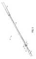
- FIG. 2is a side view of an examplary delivery apparatus in accordance with the present invention for delivering the stent shown in FIG. 1;
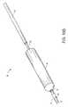
- FIG. 3is a close-up perspective view of the distal area of the delivery apparatus shown in FIG. 2;
- FIG. 4is a further close-up perspective view of the distal area of delivery apparatus shown in FIG. 2;
- FIG. 5is a close-up side view of the hand piece and y-connector of the delivery apparatus shown in FIG. 2;
- FIG. 6is a cross-sectional view of the hand piece shown in FIG. 2 with the lever in a retracted position;
- FIG. 7is a cross-sectional view of the hand piece shown in FIG. 2 with the lever in an extended position;
- FIGS. 8A-8Dillustrate a method of compressing the stent according to the present invention
- FIGS. 9A-9Cillustrate another method of compressing the stent according to the present invention.
- FIGS. 10A-10Fillustrate various stages in the deployment of the stent shown in FIG. 1 .
- the present inventionrelates to a method and apparatus for intraluminal delivery and deployment of an expandable prosthesis at a site within a body canal.
- the apparatusis shown to deploy a self-expandable stent for a blood vessel.
- the principles of the inventionare equally applicable to virtually any expandable prosthesis.
- the apparatusmay be used to deliver a self-expanding or balloon expandable graft, stent-graft or the like. Therefore, the present invention should not be limited to the specific embodiment shown and such principles should be broadly construed.
- the stent 10comprises a wire frame 12 having a flexible tubular shape with rows of interconnected cells 14 , and the ends of the frame 16 , 18 include loops 20 extending longitudinally outward in the distal and proximal direction.
- the wire frame 12is covered by an inner liner 22 and an outer liner 24 , where the inner and outer liner encase or sandwich the frame.
- the liners 22 , 24may be joined together and affixed to the frame 12 by stitching, heat welding, ultrasonic welding or the like.
- the liners 22 , 24are formed from polytetrafluoroethylene (PTFE) and are joined together by a process disclosed and claimed in commonly assigned U.S. Pat. No. 5,928,279, which is incorporated by reference as if fully described herein. It is contemplated that the length of the stent 10 may range from about 20 mm to 500 mm, preferably from 20 to 100 mm, and the relaxed diameter range from about 4 mm to 45 mm, preferably being in the range from about 5 mm to 25 mm.
- PTFEpolytetrafluoroethylene
- Such stents 10are particularly suitable for the treatment of various occlusive conditions such as atherosclerotic or arteriosclerotic iliac artery stenosis and provides mechanical support to compress intimal flaps and dissections against the vessel wall after percutaneous tranluminal angioplasty. Additionally, the stent 10 mechanically supports arterial sclerotic plaque in the vessel passage, which inhibits restenosis and occlusion. The stent 10 may also be used for other applications such as to bridge an aneursym, or in a biliary, coronary, cerebral or any peripheral vascular site.
- a delivery and deployment apparatus 50configured in accordance with the principles of the present invention is illustrated. It is noted that the delivery apparatus 50 may also be used to deliver non self-expanding prostheses such as a balloon expandable stent.
- the delivery apparatus 50comprises a catheter assembly 52 , a connector 54 , and a hand piece 56 .
- a proximal end of the connector 54is coupled to the hand piece 56 by a tube 58 , and the catheter assembly 52 extends outwardly from a proximal end of the connector 54 .
- the catheter assembly 52is about 110 cm in length and includes a tubular sleeve 62 , an outer shaft 64 , and an inner shaft 66 .
- the sleeve 62has a lumen extending from a proximal end to a distal end, and the stent 10 (not shown) is housed within a distal area of the lumen in a compressed state.
- the outer shaft 64is slidably received within the lumen and extends proximally beyond the proximal end of the sleeve 62 .
- the outer shaft 64has a lumen extending from a proximal end to a distal end, and the inner shaft 66 is slidably received within the lumen of the outer shaft 64 .
- the proximal end of the inner shaft 66extends proximally beyond the proximal end of the outer shaft 64 and is fixedly secured to the hand piece 56 .
- the inner shaft 66has a lumen for the passage of a guide wire (not shown) or other devices.
- a securing member 68extends outwardly from the distal end of the outer shaft 64 .
- the securing member 68is shown as a fork-shaped element 70 having a plurality of prongs 72 extending distally.
- Each prong 72engages with one of the distally located loops 20 of the wire frame 12 .
- any arrangement capable of securing the distal area of the stent to the outer shaftmay be used.
- the distal area of the stentmay be secured with retractable pins extending radially outwardly from the outer shaft, wherein the stent is in a secured state with the pins extended and in an unsecured state with the pins retracted.
- the distal end of the inner shaft 66includes an atraumatic tip 74 to prevent trauma to the body canal.
- the atraumatic tip 74has a distal port 76 and at least one side port 78 for the release of a contrast media or other solutions such as saline, lactated ringer, dextran solution, antibacterial, or angiogenic growth factors.
- a distal portion of the atraumatic tip 74is tapered to reduce the likelihood of damaging the tissue of the body canal.
- the distal area of the stent 10is lockingly secured to the securing member 68 by having the prongs 72 engage with the loops 20 and abut against the proximal end of the atraumatic tip 74 .
- the sleeve 62should be strong enough to withstand the expansion force of the stent 10 but must also be flexible to allow intravascular atraumatic maneuvering.
- the sleeve 62may be formed of a high strength thermoplastic elastomer such as nylon, PTFE, polyvinylchloride, PEEKTM, ULTEMTM or PEBAXTM or the like.
- the sleeve 62may be formed of a braided reinforced polymer tubing or a liner reinforced tubing, preferably having fiber of a polyamide such as VECTRANTM, KEVLARTM, SPECTRATM or the like embedded to improve tensile strength without reducing flexibility.
- the outer shaft 64provides high column strength with flexibility and may be helically formed from a tightly wound, high strength material such as reinforced stainless steel wound over polyimide tubing.
- the inner shaft 66may be formed from a polyamide such as ULTEMTM, PEEKTM, polyvinylchloride, nylon or PTFE, or a thermoset plastic such as polyimide.
- one or more marker elements 80may be located at a predetermined position on the sleeve 62 , outer shaft 64 , and/or inner shaft 66 .
- the marker elements 80may be a band of metal or radiopaque material attached to the periphery of the sleeve, whereby correct placement of the catheter assembly 52 prior to deployment of the stent 10 may be checked by fluoroscopy.
- the atraumatic tip 74includes a radiopaque element 82 , thereby giving an indication of the location of the distal end of the stent 10 during fluorscopically guided prostheses placement.
- the connector 54comprises a Y-shaped body 84 having mating threaded connector 86 at the proximal end and a compression nut 88 at the distal end.
- the proximal end of the body 84is fixedly secured to a distal end of the tube 58 by the mating threaded connector 86 .
- the catheter assembly 52is disposed within the tube 58 and Y-shaped body and extends outwardly from the compression nut 88 .
- a three-way stop-cock 92may be connected to an auxiliary port 94 of the body 84 by a luer connector 96 . Fluids such as a contrast medium may be introduced into the body canal through the stop-cock 92 .
- the hand piece 56is shown.
- the force required to withdraw the sleeve 62is substantial, typically in the range of about 5 lbs.
- the hand piece 56is provided with a lever mechanism 96 to provide a mechanical advantage ratio of about ten to one.
- the level mechanism 96is shown in a retracted position in FIG. 6 and in an extended position in FIG. 7 .
- the lever mechanism 96includes the tube 58 , a slider 100 , an arm 102 , and a lever arm 104 .
- the tube 58is secured to the sleeve 62 and is slidable relative to the body of the hand piece 56 .
- a first spring 106is provided to bias the tube 58 towards the distal direction.
- the slider 100engages and disengages with the tube 58 to drive the tube 58 in the longitudinal and proximal direction, and a second spring 108 biases the slider 100 towards the distal direction.
- the lever arm 104is connected to the slider 100 via the arm 102 .
- the stent 10may be incrementally exposed in a precise manner by pressing the lever arm 104 , wherein a single stroke drives the tube 58 and sleeve 62 approximately 3 mm in the proximal direction.
- full deploymentmay require the lever arm 104 to be pressed in the range of about 20-30 times.
- the hand piece 56further includes a release mechanism 110 for releasing the stent 10 from the securing member 68 .
- the release mechanism 110comprises a release knob 112 , a rod 114 , and a release slider 116 .
- the knob 112is fixedly connected to the rod 114
- the rod 114is fixedly connected to the release slider 116
- the release slider 116is fixedly connected to a proximal area of the outer shaft 64 .
- Operation of the delivery apparatus 50is as follows. Before loading the stent 10 within the sleeve 62 , it must be adequately compressed. As shown in FIG. 8A, the outer shaft 64 is secured to the stent 10 by engaging the prongs 72 of the securing member 68 with the loop (not shown) of the wire frame 12 . As shown in FIG. 8B, the stent 10 and outer shaft 64 are placed within an expandable, meshed tube 118 . As shown in FIG.
- the stent 10 , outer shaft 64 and meshed tube 118are drawn into a first sizing 120 tube having an inner diameter less than the outer diameter of the expanded stent 10 , whereby the outer diameter of the stent 10 is reduced to the inner diameter of the sizing tube 120 during the drawing procedure.
- a portion of a second sizing tube 122which has an inner diameter less than the inner diameter of the first sizing tube 120 , is placed within the first sizing tube 120 .
- the meshed tube 118 , stent 10 and outer shaft 64are drawn into the second sizing tube 122 . Additional sizing tubes with incrementally smaller inner diameters may be used to further compress the stent 10 .
- FIGS. 9A-9CAn alternative method to compress the fully expanded stent 10 is shown in FIGS. 9A-9C.
- the outer shaft 64is secured to the stent 10 by engaging the prongs 72 of the securing member 68 with the loops (not shown) of the wire frame 12 .
- the stent 10 and outer shaft 64are placed within the expandable, meshed tube 118 .
- the meshed tube 118 , stent 10 and outer shaft 64are drawn into a conically shaped sizing tube 124 , wherein the inner diameter of a load end 126 is larger that an exit end 128 .
- other meansmay be utilized to compress the stent such as by using pull wires run through the stent loops, or by crimping, folding, or wrapping.
- the compressed stent 10is transferred from the sizing tube 122 or 124 to the distal area of the sleeve 62 by sliding the outer shaft 64 into the lumen of the sleeve 62 .
- the meshed tube 118is removed from the outer shaft 64 .
- the inner shaft 66is passed through the outer shaft 64 until the atraumatic tip 74 abuts against the securing member 68 .
- FIG. 10Aillustrates the distal area of the catheter assembly 52 when in a pre-deployment stage.
- a guide wire(not shown) may be positioned at the occlusion site.
- the catheter assembly 52is passed over the guide wire via the lumen of the inner shaft 66 and directed to the occlusion site. With the catheter assembly 52 properly positioned within the body canal.
- the guide wiremay be retained within the inner shaft 66 until the stent 10 is deployed at the desired location and withdrawn together with the catheter assembly. Alternatively, the guide wire may be withdrawn prior to deployment of the stent 10 so that correct positioning of the stent 10 , while still within the catheter assembly 52 , may be verified by endoscopic or fluoroscopic means or the like.
- the positioning of the catheter assembly 52 within the body canalmay be monitored and verified by locating the one or more marker elements 80 by use of an endoscope or by fluoroscopy.
- the stent 10is then deployed by retracting the sleeve 62 relative to the outer shaft 64 and by retracting the outer shaft relative to the inner shaft 66 .
- the operationis performed by gripping the hand piece 56 and repeatedly pressing the lever arm 104 to incrementally retract the sleeve 62 in the longitudinal and proximal direction, thus exposing the stent 10 .
- FIGS. 10B and 10Cillustrate the stent 10 in a partially exposed state.
- the exposed portion of the stent 10is free to partially expand.
- the positioning of the stent 10 within the body canalis rechecked. If the position is correct, retraction of the sleeve 62 is continued until the stent 10 is clear of the sleeve 62 as shown in FIG. 10 D.
- the release member knob 112is actuated, and the inner shaft 66 and securing member 68 are retracted in the longitudinal and proximal direction. The stent 10 is released from the securing member 68 as shown in FIG.
- the catheter assembly 52is then withdrawn from the stent 10 as shown in FIG. 10 F.
- the monitoringreveals that the stent 10 is not in its proper position, further retraction of the sleeve 62 is terminated.
- the catheter assembly 52may be repositioned as required, and the deployment operation can be completed with the stent 10 in its correct position.
- one of the advantages of the present inventionis that repositioning of the catheter assembly 52 does not require the step of fully compressing the stent 10 by distally driving the sleeve 62 to fully enclose the stent 10 .
- the column strength of the stentactually aids in repositioning.
- the catheter assemblymay comprise only two elongated members.
- the first elongated membermay contain the stent, while the second elongated member has a clamping mechanism at its distal area which does not require an inner shaft to lockingly secure the stent,
- the clamping mechanismmay have retractable pins which lockingly secure the stent. During deployment of the stent, the pins may be retracted from the second elongated member.
- other meansmay be utilized to drive the sleeve, outer shaft, and inner shaft.
- the sleevemay have a first handle at its proximal end, and the outer shaft may have a second handle at its proximal end.
- the sleevemay be retracted by holding the first handle and pulling it in the proximal direction, thus exposing the stent.
- the stentmay be released from the securing member by holding the second handle and pulling it in the proximal direction.
- the sleeve and outer shaftmay be contained within rotatable transfer assemblies similar to a fly, fishing reel. Accordingly, the invention is not limited to the precise embodiment shown in the drawings and described in detail hereinabove.
Landscapes
- Health & Medical Sciences (AREA)
- Engineering & Computer Science (AREA)
- Biomedical Technology (AREA)
- Cardiology (AREA)
- Oral & Maxillofacial Surgery (AREA)
- Transplantation (AREA)
- Heart & Thoracic Surgery (AREA)
- Vascular Medicine (AREA)
- Life Sciences & Earth Sciences (AREA)
- Animal Behavior & Ethology (AREA)
- General Health & Medical Sciences (AREA)
- Public Health (AREA)
- Veterinary Medicine (AREA)
- Media Introduction/Drainage Providing Device (AREA)
- Prostheses (AREA)
- Spectrometry And Color Measurement (AREA)
- Farming Of Fish And Shellfish (AREA)
Abstract
Description
The invention relates generally to an apparatus and method for delivering and deploying an expandable prosthesis within a body canal.
Prostheses for transluminal implantation in body canals, such as blood vessels, for repair or dilation are known in the art. These prostheses may be tubular elements which are non-extendible or extendible (i.e. adapted to extend longitudinally), or they may be self-expanding in the transverse direction or expandable in the transverse direction by a dilation balloon. A typical self-expanding stent is disclosed in U.S. Pat. No. 4,655,771 to Wallsten. The stent has a radially and axially flexible, elastic tubular body with a predetermined diameter that is variable under axial movement of the ends and which comprises a plurality of individually rigid but flexible and elastic wire elements defining a radially self-expanding helix. This type of stent is known in the art as a “braided stent.”
Another stent, which has particular applicability to the present invention is disclosed in U.S. Pat. No. 5,545,211 An et al. This stent has a greater tendency to resist foreshortening. It also has a significantly improved hoop strength which it is believed provides more radial force for maintaining the patency of a vessel lumen. As a consequence, this stent tends to resist compression.
A typical stent delivery device comprises a catheter assembly having a tubular sleeve with a self-expandable stent placed in contracted condition within a distal area of the sleeve. The sleeve is positioned by means of a guide wire and an introducer. The device further includes a means to expose the stent by sliding the sleeve away from the stent. The device can be directed to the site of implantation where the stent is released from the sleeve and implanted into the body canal.
One of the problems related to the placement of self-expanding prostheses such as stents is that they are highly compressed within delivery catheters to permit them to be maneuvered within the vascular system. The compressive forces necessary to reduce the stent have been found to lead to excessive friction between the stent and sleeve during deployment from the delivery catheters. Excessive friction may be particularly noticeable for stents which provide relative large radial forces for maintaining the patency of a body canal, such as the stent disclosed in U.S. Pat. No. 5,545,211. In addition, visualization of a compressed stent within the catheter is problematic, particularly when the stent must be placed near a branching body canal. Currently, hand held devices with pivoting levers have been utilized to provide the necessary forces to deploy the stent. Deployment of the stent at the desired location sometimes involves the process of partially deploying the stent and determining whether the stent is properly located in the vessel. The deployed portion of the stent may expand and impinge against the internal wall of the body canal. If the stent is improperly positioned, the stent may have to be recompressed and recaptured within the sleeve before moving it to a new location because friction between the stent and body canal would otherwise prevent movement of the prosthesis and/or because the body canal may be damaged by sliding the stent against the internal wall of the body canal. In some cases, it may not be possible to recompress and recapture the stent within the sleeve if the stent provide large radial forces for maintaining patency of a body canal.
Thus, there remains a need for a delivery device that is capable of partially deploying a stent and thereafter repositioning the partially deployed stent. There is also a need for repositioning a stent without having to recapture the stent within the sleeve. And, there is a need for partially deploying a stent having a high compressive force and repositioning such a stent.
In accordance with the present invention, a delivery and deployment apparatus is provided that is capable of partially deploying a stent and thereafter repositioning the stent without having to recapture the stent within a sleeve. The system of the present invention further permits the sleeve to be partially withdrawn and the delivery catheter to be repositioned without excessive frictional engagement with the body canal. The invention has particular applicability with a stent having a high compressive force, since the device of the present invention does not require recompression of the stent and recapture within the sleeve. Furthermore, the delivery apparatus actually utilizes the stent's compressive force to its advantage in that the repositioning of the stent relies on the column strength of the partially deployed stent to accurately reposition it.
In accordance with an illustrative embodiment of the present invention, the delivery apparatus comprises an elongated sleeve having a proximal end and a distal area with a distal end. A self-expandable prosthesis is placed in contracted condition within the distal area. An outer shaft is disposed within the sleeve and movable relative to the sleeve. A securing member is disposed on a distal area of the outer shaft, and a distal area of the prosthesis is secured to the outer shaft by the securing member. The delivery apparatus may further include an inner shaft which is disposed within the outer shaft and movable relative to the outer shaft. A tip is disposed at a distal end of the inner shaft and includes at least one side port for bleeding contrast medium adjacent to the atraumatic tip. The inner shaft may further include a lumen for receiving a guide wire.
The delivery apparatus may be operated in the following manner. The prosthesis is compressed and loaded into the distal area of the sleeve. The outer shaft is positioned within the prosthesis and sleeve, and the distal area of the prosthesis is secured to the securing member. Via the distal end of the outer shaft, the inner shaft is passed through the outer shaft until the atraumatic tips abuts against the securing member, thereby lockingly securing the prosthesis. With the prosthesis properly positioned within the body canal, the prosthesis is deployed by causing a longitudinal motion between the sleeve and outer shaft to expose the prosthesis and by releasing the securing member from the distal area of the prosthesis. If the prosthesis requires repositioning, retraction of the sleeve is terminated prior to releasing the prosthesis from the securing member. The prosthesis is then repositioned, the sleeve is fully retracted, and the prosthesis is released from the securing member.
Other objects, features, and advantages of the present invention will become apparent from a consideration of the following detailed description.
FIG. 1 is a side view of a vascular stent which is exemplary of the type of radially compressible tubular prosthesis which may be placed using a delivery apparatus in accordance with the present invention;
FIG. 2 is a side view of an examplary delivery apparatus in accordance with the present invention for delivering the stent shown in FIG. 1;
FIG. 3 is a close-up perspective view of the distal area of the delivery apparatus shown in FIG. 2;
FIG. 4 is a further close-up perspective view of the distal area of delivery apparatus shown in FIG. 2;
FIG. 5 is a close-up side view of the hand piece and y-connector of the delivery apparatus shown in FIG. 2;
FIG. 6 is a cross-sectional view of the hand piece shown in FIG. 2 with the lever in a retracted position;
FIG. 7 is a cross-sectional view of the hand piece shown in FIG. 2 with the lever in an extended position;
FIGS. 8A-8D illustrate a method of compressing the stent according to the present invention;
FIGS. 9A-9C illustrate another method of compressing the stent according to the present invention; and
FIGS. 10A-10F illustrate various stages in the deployment of the stent shown in FIG.1.
The present invention relates to a method and apparatus for intraluminal delivery and deployment of an expandable prosthesis at a site within a body canal. In the particular embodiment shown in the drawings and herein described, the apparatus is shown to deploy a self-expandable stent for a blood vessel. However, it should be understood that the principles of the invention are equally applicable to virtually any expandable prosthesis. For example, the apparatus may be used to deliver a self-expanding or balloon expandable graft, stent-graft or the like. Therefore, the present invention should not be limited to the specific embodiment shown and such principles should be broadly construed.
Referring to FIG. 1, an examplary prosthesis in the form of a self-expandable stent 10 is illustrated. Thestent 10 comprises awire frame 12 having a flexible tubular shape with rows ofinterconnected cells 14, and the ends of theframe 16,18 include loops20 extending longitudinally outward in the distal and proximal direction. Thewire frame 12 is covered by aninner liner 22 and anouter liner 24, where the inner and outer liner encase or sandwich the frame. Theliners frame 12 by stitching, heat welding, ultrasonic welding or the like. In the exemplary embodiment, theliners stent 10 may range from about 20 mm to 500 mm, preferably from 20 to 100 mm, and the relaxed diameter range from about 4 mm to 45 mm, preferably being in the range from about 5 mm to 25 mm.Such stents 10 are particularly suitable for the treatment of various occlusive conditions such as atherosclerotic or arteriosclerotic iliac artery stenosis and provides mechanical support to compress intimal flaps and dissections against the vessel wall after percutaneous tranluminal angioplasty. Additionally, thestent 10 mechanically supports arterial sclerotic plaque in the vessel passage, which inhibits restenosis and occlusion. Thestent 10 may also be used for other applications such as to bridge an aneursym, or in a biliary, coronary, cerebral or any peripheral vascular site.
Referring to FIG. 2, a delivery anddeployment apparatus 50 configured in accordance with the principles of the present invention is illustrated. It is noted that thedelivery apparatus 50 may also be used to deliver non self-expanding prostheses such as a balloon expandable stent. Thedelivery apparatus 50 comprises acatheter assembly 52, aconnector 54, and ahand piece 56. A proximal end of theconnector 54 is coupled to thehand piece 56 by atube 58, and thecatheter assembly 52 extends outwardly from a proximal end of theconnector 54.
Referring to FIGS. 3 and 4, thecatheter assembly 52 is about 110 cm in length and includes atubular sleeve 62, anouter shaft 64, and aninner shaft 66. Thesleeve 62 has a lumen extending from a proximal end to a distal end, and the stent10 (not shown) is housed within a distal area of the lumen in a compressed state. Theouter shaft 64 is slidably received within the lumen and extends proximally beyond the proximal end of thesleeve 62. Theouter shaft 64 has a lumen extending from a proximal end to a distal end, and theinner shaft 66 is slidably received within the lumen of theouter shaft 64. The proximal end of theinner shaft 66 extends proximally beyond the proximal end of theouter shaft 64 and is fixedly secured to thehand piece 56. Theinner shaft 66 has a lumen for the passage of a guide wire (not shown) or other devices. A securingmember 68 extends outwardly from the distal end of theouter shaft 64. In the examplary embodiment, the securingmember 68 is shown as a fork-shapedelement 70 having a plurality ofprongs 72 extending distally. Eachprong 72 engages with one of the distally located loops20 of thewire frame 12. Of course, any arrangement capable of securing the distal area of the stent to the outer shaft may be used. For example, the distal area of the stent may be secured with retractable pins extending radially outwardly from the outer shaft, wherein the stent is in a secured state with the pins extended and in an unsecured state with the pins retracted. The distal end of theinner shaft 66 includes anatraumatic tip 74 to prevent trauma to the body canal. Theatraumatic tip 74 has adistal port 76 and at least oneside port 78 for the release of a contrast media or other solutions such as saline, lactated ringer, dextran solution, antibacterial, or angiogenic growth factors. A distal portion of theatraumatic tip 74 is tapered to reduce the likelihood of damaging the tissue of the body canal. The distal area of thestent 10 is lockingly secured to the securingmember 68 by having theprongs 72 engage with the loops20 and abut against the proximal end of theatraumatic tip 74.
Thesleeve 62 should be strong enough to withstand the expansion force of thestent 10 but must also be flexible to allow intravascular atraumatic maneuvering. Thesleeve 62 may be formed of a high strength thermoplastic elastomer such as nylon, PTFE, polyvinylchloride, PEEK™, ULTEM™ or PEBAX™ or the like. Alternatively, thesleeve 62 may be formed of a braided reinforced polymer tubing or a liner reinforced tubing, preferably having fiber of a polyamide such as VECTRAN™, KEVLAR™, SPECTRA™ or the like embedded to improve tensile strength without reducing flexibility. Theouter shaft 64 provides high column strength with flexibility and may be helically formed from a tightly wound, high strength material such as reinforced stainless steel wound over polyimide tubing. Theinner shaft 66 may be formed from a polyamide such as ULTEM™, PEEK™, polyvinylchloride, nylon or PTFE, or a thermoset plastic such as polyimide.
To facilitate proper placement of thecatheter assembly 52, one or more marker elements80 may be located at a predetermined position on thesleeve 62,outer shaft 64, and/orinner shaft 66. The marker elements80 may be a band of metal or radiopaque material attached to the periphery of the sleeve, whereby correct placement of thecatheter assembly 52 prior to deployment of thestent 10 may be checked by fluoroscopy. Preferably, theatraumatic tip 74 includes a radiopaque element82, thereby giving an indication of the location of the distal end of thestent 10 during fluorscopically guided prostheses placement.
Referring to FIG. 5, theconnector 54 comprises a Y-shapedbody 84 having mating threaded connector86 at the proximal end and a compression nut88 at the distal end. The proximal end of thebody 84 is fixedly secured to a distal end of thetube 58 by the mating threaded connector86. Thecatheter assembly 52 is disposed within thetube 58 and Y-shaped body and extends outwardly from the compression nut88. A three-way stop-cock 92 may be connected to anauxiliary port 94 of thebody 84 by aluer connector 96. Fluids such as a contrast medium may be introduced into the body canal through the stop-cock 92.
Referring back to FIG.5 and FIGS. 6-7, thehand piece 56 is shown. The force required to withdraw thesleeve 62 is substantial, typically in the range of about 5 lbs. For this reason, thehand piece 56 is provided with alever mechanism 96 to provide a mechanical advantage ratio of about ten to one. Thelevel mechanism 96 is shown in a retracted position in FIG.6 and in an extended position in FIG.7. Thelever mechanism 96 includes thetube 58, aslider 100, anarm 102, and alever arm 104. Thetube 58 is secured to thesleeve 62 and is slidable relative to the body of thehand piece 56. Afirst spring 106 is provided to bias thetube 58 towards the distal direction. Theslider 100 engages and disengages with thetube 58 to drive thetube 58 in the longitudinal and proximal direction, and asecond spring 108 biases theslider 100 towards the distal direction. Thelever arm 104 is connected to theslider 100 via thearm 102. Thus, thestent 10 may be incrementally exposed in a precise manner by pressing thelever arm 104, wherein a single stroke drives thetube 58 andsleeve 62 approximately 3 mm in the proximal direction. Depending on the length of thestent 10, full deployment may require thelever arm 104 to be pressed in the range of about 20-30 times.
Referring back to FIGS. 5-7, thehand piece 56 further includes arelease mechanism 110 for releasing thestent 10 from the securingmember 68. Therelease mechanism 110 comprises arelease knob 112, arod 114, and arelease slider 116. Theknob 112 is fixedly connected to therod 114, therod 114 is fixedly connected to therelease slider 116, and therelease slider 116 is fixedly connected to a proximal area of theouter shaft 64. When therelease slider 116 is secured to theouter shaft 64, movement of theknob 112 in the proximal direction causes therod 114,release slider 116, andouter shaft 64 to move in the proximal direction, and thestent 10 is released from the securingmember 68.
Clearly, a wide variety of mechanical linkages are available to move the outer sleeve and outer shaft in the distal and proximal directions. It is particularly advantageous to provide a mechanism which allows manipulation with a single hand, thus allowing the alternate hand to manipulate the outer sleeve relative to the hand piece.
Operation of thedelivery apparatus 50 is as follows. Before loading thestent 10 within thesleeve 62, it must be adequately compressed. As shown in FIG. 8A, theouter shaft 64 is secured to thestent 10 by engaging theprongs 72 of the securingmember 68 with the loop (not shown) of thewire frame 12. As shown in FIG. 8B, thestent 10 andouter shaft 64 are placed within an expandable,meshed tube 118. As shown in FIG. 8C, thestent 10,outer shaft 64 andmeshed tube 118 are drawn into a first sizing120 tube having an inner diameter less than the outer diameter of the expandedstent 10, whereby the outer diameter of thestent 10 is reduced to the inner diameter of the sizingtube 120 during the drawing procedure. As shown in FIG. 8D, a portion of asecond sizing tube 122, which has an inner diameter less than the inner diameter of thefirst sizing tube 120, is placed within thefirst sizing tube 120. Themeshed tube 118,stent 10 andouter shaft 64 are drawn into thesecond sizing tube 122. Additional sizing tubes with incrementally smaller inner diameters may be used to further compress thestent 10.
An alternative method to compress the fully expandedstent 10 is shown in FIGS. 9A-9C. As shown in FIG. 9A, theouter shaft 64 is secured to thestent 10 by engaging theprongs 72 of the securingmember 68 with the loops (not shown) of thewire frame 12. As shown in FIG. 9B, thestent 10 andouter shaft 64 are placed within the expandable,meshed tube 118. As shown in FIG. 9C, themeshed tube 118,stent 10 andouter shaft 64 are drawn into a conically shaped sizingtube 124, wherein the inner diameter of aload end 126 is larger that anexit end 128. It is noted that other means may be utilized to compress the stent such as by using pull wires run through the stent loops, or by crimping, folding, or wrapping.
To prepare thecatheter assembly 52, thecompressed stent 10 is transferred from the sizingtube sleeve 62 by sliding theouter shaft 64 into the lumen of thesleeve 62. Themeshed tube 118 is removed from theouter shaft 64. Via the distal end of theouter shaft 64, theinner shaft 66 is passed through theouter shaft 64 until theatraumatic tip 74 abuts against the securingmember 68. FIG. 10A illustrates the distal area of thecatheter assembly 52 when in a pre-deployment stage.
Assuming an introducer (not shown) has been inserted into the body canal, a guide wire (not shown) may be positioned at the occlusion site. Thecatheter assembly 52 is passed over the guide wire via the lumen of theinner shaft 66 and directed to the occlusion site. With thecatheter assembly 52 properly positioned within the body canal. The guide wire may be retained within theinner shaft 66 until thestent 10 is deployed at the desired location and withdrawn together with the catheter assembly. Alternatively, the guide wire may be withdrawn prior to deployment of thestent 10 so that correct positioning of thestent 10, while still within thecatheter assembly 52, may be verified by endoscopic or fluoroscopic means or the like.
The positioning of thecatheter assembly 52 within the body canal may be monitored and verified by locating the one or more marker elements80 by use of an endoscope or by fluoroscopy. When the correct position for proper placement of thestent 10 is reached and verified, thestent 10 is then deployed by retracting thesleeve 62 relative to theouter shaft 64 and by retracting the outer shaft relative to theinner shaft 66. The operation is performed by gripping thehand piece 56 and repeatedly pressing thelever arm 104 to incrementally retract thesleeve 62 in the longitudinal and proximal direction, thus exposing thestent 10. FIGS. 10B and 10C illustrate thestent 10 in a partially exposed state. At this stage, the exposed portion of thestent 10, with the exception of the distal area, is free to partially expand. Before thestent 10 is completely exposed, the positioning of thestent 10 within the body canal is rechecked. If the position is correct, retraction of thesleeve 62 is continued until thestent 10 is clear of thesleeve 62 as shown in FIG.10D. To release thestent 10 from theouter shaft 64, therelease member knob 112 is actuated, and theinner shaft 66 and securingmember 68 are retracted in the longitudinal and proximal direction. Thestent 10 is released from the securingmember 68 as shown in FIG. 10E, and thecatheter assembly 52 is then withdrawn from thestent 10 as shown in FIG.10F. However, if the monitoring reveals that thestent 10 is not in its proper position, further retraction of thesleeve 62 is terminated. Since the securingmember 68 prevents the stent from being fully expanded, thecatheter assembly 52 may be repositioned as required, and the deployment operation can be completed with thestent 10 in its correct position. As discussed above, one of the advantages of the present invention is that repositioning of thecatheter assembly 52 does not require the step of fully compressing thestent 10 by distally driving thesleeve 62 to fully enclose thestent 10. Furthermore, when deploying a stent with high compressibility, the column strength of the stent actually aids in repositioning.
Although the present invention has been described in detail with regarding the exemplary embodiment and drawings thereof, it should be apparent to those skilled in the art that various adaptations may be accomplished without departing from the spirit and scope of the invention. For example, the catheter assembly may comprise only two elongated members. The first elongated member may contain the stent, while the second elongated member has a clamping mechanism at its distal area which does not require an inner shaft to lockingly secure the stent, For example, the clamping mechanism may have retractable pins which lockingly secure the stent. During deployment of the stent, the pins may be retracted from the second elongated member. Further, other means may be utilized to drive the sleeve, outer shaft, and inner shaft. For example, the sleeve may have a first handle at its proximal end, and the outer shaft may have a second handle at its proximal end. The sleeve may be retracted by holding the first handle and pulling it in the proximal direction, thus exposing the stent. The stent may be released from the securing member by holding the second handle and pulling it in the proximal direction. In another example, the sleeve and outer shaft may be contained within rotatable transfer assemblies similar to a fly, fishing reel. Accordingly, the invention is not limited to the precise embodiment shown in the drawings and described in detail hereinabove.
Claims (4)
1. A method for deploying a prosthesis within a body canal, the method comprising:
providing an outer shaft having a distal area, the distal area having a securing member;
securing a distal area of the prosthesis onto the outer shaft with the securing member;
providing a sleeve having a distal area;
containing the prosthesis within the distal area of the sleeve and positioning the outer shaft within the sleeve;
the process further comprising the steps of:
positioning the prosthesis within the body canal at a desired location; and
deploying the prosthesis at the desired location by causing longitudinal motion between the sleeve and the outer shaft to expose the prosthesis, keeping the distal area of the prosthesis engaged with the securing member while permitting the exposed portion of the prosthesis to be free to partially expand;
wherein the step of providing a hand piece includes having a lever arm coupled to the sleeve;
actuating the lever arm to incrementally and precisely drive the sleeve in a longitudinal and proximal direction such that the sleeve moves in a proximal direction relative to the outer shaft;
fully exposing the prosthesis while maintaining securement to the outer shaft by the securing member; and
releasing the prosthesis from the outer shaft by disengaging the securing member;
while re-positioning the prosthesis within the body canal at a desired location;
fully exposing the prosthesis while maintaining securement to the outer shaft by the securing member; and
releasing the prosthesis from the outer shaft by disengaging the securing member; the method likewise including the steps of:
providing an inner shaft having a distal area, the distal area having a tip;
positioning the inner shaft within the outer shaft in a slidable manner;
wherein the securing member is a fork-shaped element having at least one prong which engages with the distal area of the prosthesis;
lockingly securing the prosthesis onto the securing member by slidingly coupling the inner shaft with the outer shaft so that a distal end of the at least one prong abuts against a proximal end of the tip; and
releasing the prosthesis from the securing member by longitudinally and proximally sliding the inner shaft relative to the outer shaft so that the securing member is slidingly displaced away from the tip.
2. A method for deploying a prosthesis within a body canal, the method comprising:
providing an outer shaft having a distal area, the distal area having a securing member;
securing a distal area of the prosthesis onto the outer shaft with the securing member;
providing a sleeve having a distal area;
containing the prosthesis with the distal area of the sleeve and positioning the outer shaft within the sleeve;
the process further comprising the steps of:
positioning the prosthesis within the body canal at a desired location; and
deploying the prosthesis at the desired location by causing longitudinal motion between the sleeve and the outer shaft to expose the prosthesis, keeping the distal area of the prosthesis engaged with the securing member while permitting the exposed portion of the prosthesis to be free to partially expand;
wherein the step of providing a hand piece includes having a lever arm coupled to the sleeve;
actuating the lever arm to incrementally and precisely drive the sleeve in a longitudinal and proximal direction such that the sleeve moves in a proximal direction relative to the outer shaft;
fully exposing the prosthesis while maintaining securement to the outer shaft by the securing member; and
releasing the prosthesis from the outer shaft by disengaging the securing member;
while re-positioning the prosthesis within the body canal at a desired location;
fully exposing the prosthesis while maintaining securement to the outer shaft by the securing member; and
releasing the prosthesis from the outer shaft by disengaging the securing member; the method likewise including the steps of:
providing an inner shaft having a distal area, the distal area having a tip;
positioning the inner shaft within the outer shaft in a slidable manner;
wherein the securing member is a fork-shaped element having at least one prong which engages with the distal area of the prosthesis;
lockingly securing the prosthesis onto the securing member by slidingly coupling the inner shaft with the outer shaft so that a distal end of the at least one prong abuts against a proximal end of the tip; and
releasing the prosthesis from the securing member by longitudinally and proximally sliding the inner shaft relative to the outer shaft so that the securing member is slidingly displaced away from the tip;
whereby, the process comprises the step of providing the tip with a side port for the release of a contrast medium into the body canal, whereby the contrast agent is released near the prosthesis, and whereby said tip is an atraumatic tip for reducing injury to the body canal.
3. A method for deploying a prosthesis within a body canal, the method comprising:
providing an outer shaft having a distal area, the distal area having a securing member;
securing a distal area of the prosthesis onto the outer shaft with the securing member;
providing a sleeve having a distal area;
containing the prosthesis within the distal area of the sleeve and positioning the outer shaft within the sleeve;
the process further comprising the steps of:
positioning the prosthesis within the body canal at a desired location; and
deploying the prosthesis at the desired location by causing longitudinal motion between the sleeve and the outer shaft to expose the prosthesis, keeping the distal area of the prosthesis engaged with the securing member while permitting the exposed portion of the prosthesis to be free to partially expand;
wherein the step of providing a hand piece includes having a lever arm coupled to the sleeve;
actuating the lever arm to incrementally and precisely drive the sleeve in a longitudinal and proximal direction such that the sleeve moves in a proximal direction relative to the outer shaft;
fully exposing the prosthesis while maintaining securement to the outer shaft by the securing member; and
releasing the prosthesis from the outer shaft by disengaging the securing member;
while re-positioning the prosthesis within the body canal at a desired location;
fully exposing the prosthesis while maintaining securement to the outer shaft by the securing member; and
releasing the prosthesis from the outer shaft by disengaging the securing member; the method likewise including the steps of:
providing an inner shaft having a distal area, the distal area having a tip;
positioning the inner shaft within the outer shaft in a slidable manner;
wherein the securing member is a fork-shaped element having at least one prong which engages with the distal area of the prosthesis;
lockingly securing the prosthesis onto the securing member by slidingly coupling the inner shaft with the outer shaft so that a distal end of the at least one prong abuts against a proximal end of the tip; and
releasing the prosthesis from the securing member by longitudinally and proximally sliding the inner shaft relative to the outer shaft so that the securing member is slidingly displaced away from the tip;
wherein the hand piece further comprises a tube connecting the sleeve to the lever arm, so that actuating the lever drives the tube in a proximal direction and movement of the tube causes the sleeve to be driven in a proximal direction.
4. A method for deploying a prosthesis within a body canal, the method comprising:
providing an outer shaft having a distal area, the distal area having a securing member;
securing a distal area of the prosthesis onto the outer shaft with the securing member;
providing a sleeve having a distal area;
containing the prosthesis within the distal area of the sleeve and positioning the outer shaft within the sleeve;
the process further comprising the steps of:
positioning the prosthesis within the body canal at a desired location; and
deploying the prosthesis at the desired location by causing longitudinal motion between the sleeve and the outer shaft to expose the prosthesis, keeping the distal area of the prosthesis engaged with the securing member while permitting the exposed portion of the prosthesis to be free to partially expand;
wherein the step of providing a hand piece includes having a lever arm coupled to the sleeve;
actuating the lever arm to incrementally and precisely drive the sleeve in a longitudinal and proximal direction such that the sleeve moves in a proximal direction relative to the outer shaft;
fully exposing the prosthesis while maintaining securement to the outer shaft by the securing member; and
releasing the prosthesis from the outer shaft by disengaging the securing member;
while re-positioning the prosthesis within the body canal at a desired location;
fully exposing the prosthesis while maintaining securement to the outer shaft by the securing member; and
releasing the prosthesis from the outer shaft by disengaging the securing member; the method likewise including the steps of:
providing an inner shaft having a distal area, the distal area having a tip;
positioning the inner shaft within the outer shaft in a slidable manner;
wherein the securing member is a fork-shaped element having at least one prong which engages with the distal area of the prosthesis;
lockingly securing the prosthesis onto the securing member by slidingly coupling the inner shaft with the outer shaft so that a distal end of the at least one prong abuts against a proximal end of the tip; and
releasing the prosthesis from the securing member by longitudinally and proximally sliding the inner shaft relative to the outer shaft so that the securing member is slidingly displaced away from the tip;
biasing the tube in a distal direction with a spring, and,
additionally including the step of:
providing the hand piece with a release member to drive the outer shaft in a proximal direction relative to the inner shaft; and
actuating the release member to release the securing member from the prosthesis.
Priority Applications (9)
| Application Number | Priority Date | Filing Date | Title |
|---|---|---|---|
| US09/503,618US6344044B1 (en) | 2000-02-11 | 2000-02-11 | Apparatus and methods for delivery of intraluminal prosthesis |
| DE60110371TDE60110371T2 (en) | 2000-02-11 | 2001-02-10 | DEVICE FOR INTRODUCING AN INTRALUMINARY PROSTHESIS |
| JP2001557500AJP3833536B2 (en) | 2000-02-11 | 2001-02-10 | Device for delivery of endovascular prostheses |
| AU36900/01AAU3690001A (en) | 2000-02-11 | 2001-02-10 | Apparatus and methods for delivery of intraluminal prostheses |
| AT01909115TATE293939T1 (en) | 2000-02-11 | 2001-02-10 | DEVICE FOR INSERTING AN INTRALUMINAL PROSTHESIS |
| PCT/US2001/004409WO2001058387A1 (en) | 2000-02-11 | 2001-02-10 | Apparatus and methods for delivery of intraluminal prostheses |
| EP01909115AEP1253875B1 (en) | 2000-02-11 | 2001-02-10 | Apparatus for delivery of intraluminal prostheses |
| CA002397978ACA2397978C (en) | 2000-02-11 | 2001-02-10 | Apparatus and methods for delivery of intraluminal prostheses |
| US09/827,062US6808529B2 (en) | 2000-02-11 | 2001-04-05 | Apparatus and methods for delivery of intraluminal prostheses |
Applications Claiming Priority (1)
| Application Number | Priority Date | Filing Date | Title |
|---|---|---|---|
| US09/503,618US6344044B1 (en) | 2000-02-11 | 2000-02-11 | Apparatus and methods for delivery of intraluminal prosthesis |
Related Child Applications (1)
| Application Number | Title | Priority Date | Filing Date |
|---|---|---|---|
| US09/827,062DivisionUS6808529B2 (en) | 2000-02-11 | 2001-04-05 | Apparatus and methods for delivery of intraluminal prostheses |
Publications (1)
| Publication Number | Publication Date |
|---|---|
| US6344044B1true US6344044B1 (en) | 2002-02-05 |
Family
ID=24002838
Family Applications (2)
| Application Number | Title | Priority Date | Filing Date |
|---|---|---|---|
| US09/503,618Expired - LifetimeUS6344044B1 (en) | 2000-02-11 | 2000-02-11 | Apparatus and methods for delivery of intraluminal prosthesis |
| US09/827,062Expired - LifetimeUS6808529B2 (en) | 2000-02-11 | 2001-04-05 | Apparatus and methods for delivery of intraluminal prostheses |
Family Applications After (1)
| Application Number | Title | Priority Date | Filing Date |
|---|---|---|---|
| US09/827,062Expired - LifetimeUS6808529B2 (en) | 2000-02-11 | 2001-04-05 | Apparatus and methods for delivery of intraluminal prostheses |
Country Status (8)
| Country | Link |
|---|---|
| US (2) | US6344044B1 (en) |
| EP (1) | EP1253875B1 (en) |
| JP (1) | JP3833536B2 (en) |
| AT (1) | ATE293939T1 (en) |
| AU (1) | AU3690001A (en) |
| CA (1) | CA2397978C (en) |
| DE (1) | DE60110371T2 (en) |
| WO (1) | WO2001058387A1 (en) |
Cited By (72)
| Publication number | Priority date | Publication date | Assignee | Title |
|---|---|---|---|---|
| US20020116048A1 (en)* | 1998-02-09 | 2002-08-22 | Chobotov Michael V. | Endovascular graft |
| US20030004560A1 (en)* | 2001-04-11 | 2003-01-02 | Trivascular, Inc. | Delivery system and method for bifurcated graft |
| US20030120331A1 (en)* | 2001-12-20 | 2003-06-26 | Trivascular, Inc. | Advanced endovascular graft |
| US20030125797A1 (en)* | 2001-12-20 | 2003-07-03 | Trivascular, Inc. | Advanced endovascular graft |
| US20030220681A1 (en)* | 2000-02-02 | 2003-11-27 | Trivascular, Inc. | Delivery system and method for expandable intracorporeal device |
| US6733521B2 (en) | 2001-04-11 | 2004-05-11 | Trivascular, Inc. | Delivery system and method for endovascular graft |
| US20040131808A1 (en)* | 2002-09-26 | 2004-07-08 | Victor Schoenle | Medical device components and processes |
| US20040138734A1 (en)* | 2001-04-11 | 2004-07-15 | Trivascular, Inc. | Delivery system and method for bifurcated graft |
| US20050033220A1 (en)* | 1998-09-10 | 2005-02-10 | Percardia, Inc. | Left ventricular conduit with blood vessel graft |
| US20050049674A1 (en)* | 2003-09-03 | 2005-03-03 | Berra Humberto A. | Stent graft |
| US20050049667A1 (en)* | 2003-09-03 | 2005-03-03 | Bolton Medical, Inc. | Self-aligning stent graft delivery system, kit, and method |
| US20050065590A1 (en)* | 2003-09-24 | 2005-03-24 | Shelso Susan I. | Stent delivery system for self-expanding stent |
| US20050171593A1 (en)* | 2004-01-30 | 2005-08-04 | Trivascular, Inc. | Inflatable porous implants and methods for drug delivery |
| US20050228484A1 (en)* | 2004-03-11 | 2005-10-13 | Trivascular, Inc. | Modular endovascular graft |
| US20060184224A1 (en)* | 2002-09-30 | 2006-08-17 | Board Of Regents, The University Of Texas System | Stent delivery system and method of use |
| US20070005129A1 (en)* | 2000-02-28 | 2007-01-04 | Christoph Damm | Anchoring system for implantable heart valve prostheses |
| US20070100440A1 (en)* | 2005-10-28 | 2007-05-03 | Jen.Cardiotec Gmbh | Device for the implantation and fixation of prosthetic valves |
| US20070135889A1 (en)* | 2003-09-03 | 2007-06-14 | Bolton Medical, Inc. | Lumen repair device with capture structure |
| US20070142906A1 (en)* | 2005-11-04 | 2007-06-21 | Jen. Cardiotec Gmbh | Self-expandable medical instrument for treating defects in a patient's heart |
| US20070198078A1 (en)* | 2003-09-03 | 2007-08-23 | Bolton Medical, Inc. | Delivery system and method for self-centering a Proximal end of a stent graft |
| US20080255661A1 (en)* | 2007-04-13 | 2008-10-16 | Helmut Straubinger | Medical device for treating a heart valve insufficiency or stenosis |
| US20080255660A1 (en)* | 2007-04-13 | 2008-10-16 | Volker Guyenot | Medical device for treating a heart valve insufficiency |
| US20090054968A1 (en)* | 2001-08-03 | 2009-02-26 | Jenavalve Technology Inc. | Implant implantation unit and procedure for implanting the unit |
| US20090099649A1 (en)* | 2007-10-04 | 2009-04-16 | Chobotov Michael V | Modular vascular graft for low profile percutaneous delivery |
| US20090156929A1 (en)* | 2007-12-17 | 2009-06-18 | Abbott Laboratories | Methods for imaging a delivery system |
| US20090171447A1 (en)* | 2005-12-22 | 2009-07-02 | Von Segesser Ludwig K | Stent-valves for valve replacement and associated methods and systems for surgery |
| US20090216313A1 (en)* | 2008-02-26 | 2009-08-27 | Helmut Straubinger | Stent for the positioning and anchoring of a valvular prosthesis |
| US20090216312A1 (en)* | 2008-02-26 | 2009-08-27 | Helmut Straubinger | Stent for the Positioning and Anchoring of a Valvular Prosthesis in an Implantation Site in the Heart of a Patient |
| US20090234443A1 (en)* | 2005-01-20 | 2009-09-17 | Ottma Ruediger | Catheter for the Transvascular Implantation of Prosthetic Heart Valves |
| US20100016943A1 (en)* | 2001-12-20 | 2010-01-21 | Trivascular2, Inc. | Method of delivering advanced endovascular graft |
| US20100030318A1 (en)* | 2003-09-03 | 2010-02-04 | Bolton Medical, Inc. | Dual Capture Device for Stent Graft Delivery System and Method for Capturing a Stent Graft |
| US20100152572A1 (en)* | 2008-12-17 | 2010-06-17 | Abbott Laboratories | Methods for imaging an implant site |
| US20100234932A1 (en)* | 2009-03-13 | 2010-09-16 | Bolton Medical, Inc. | System and method for deploying an endoluminal prosthesis at a surgical site |
| US20100292780A1 (en)* | 2009-05-15 | 2010-11-18 | Helmut Straubinger | Device for compressing a stent as well as system and method for loading a stent into a medical delivery system |
| US20100324647A1 (en)* | 2009-06-23 | 2010-12-23 | Cesar Rincon | Stent-graft securement device |
| US20110034802A1 (en)* | 2009-08-05 | 2011-02-10 | Abbott Laboratories | Systems, methods, and apparatus for imaging an implantable device and methods for manufacturing |
| US20110208290A1 (en)* | 2008-02-26 | 2011-08-25 | Helmut Straubinger | Stent for the positioning and anchoring of a valvular prosthesis in an implantation site in the heart of a patient |
| US20110238147A1 (en)* | 2009-09-22 | 2011-09-29 | Penumbra, Inc. | Manual actuation system for deployment of implant |
| US8066755B2 (en) | 2007-09-26 | 2011-11-29 | Trivascular, Inc. | System and method of pivoted stent deployment |
| US8083789B2 (en) | 2007-11-16 | 2011-12-27 | Trivascular, Inc. | Securement assembly and method for expandable endovascular device |
| US8226701B2 (en) | 2007-09-26 | 2012-07-24 | Trivascular, Inc. | Stent and delivery system for deployment thereof |
| US8328861B2 (en) | 2007-11-16 | 2012-12-11 | Trivascular, Inc. | Delivery system and method for bifurcated graft |
| US8398704B2 (en) | 2008-02-26 | 2013-03-19 | Jenavalve Technology, Inc. | Stent for the positioning and anchoring of a valvular prosthesis in an implantation site in the heart of a patient |
| US8663309B2 (en) | 2007-09-26 | 2014-03-04 | Trivascular, Inc. | Asymmetric stent apparatus and method |
| USRE45130E1 (en) | 2000-02-28 | 2014-09-09 | Jenavalve Technology Gmbh | Device for fastening and anchoring cardiac valve prostheses |
| US8992595B2 (en) | 2012-04-04 | 2015-03-31 | Trivascular, Inc. | Durable stent graft with tapered struts and stable delivery methods and devices |
| US8998970B2 (en) | 2012-04-12 | 2015-04-07 | Bolton Medical, Inc. | Vascular prosthetic delivery device and method of use |
| US9101507B2 (en) | 2011-05-18 | 2015-08-11 | Ralph F. Caselnova | Apparatus and method for proximal-to-distal endoluminal stent deployment |
| US9168130B2 (en) | 2008-02-26 | 2015-10-27 | Jenavalve Technology Gmbh | Stent for the positioning and anchoring of a valvular prosthesis in an implantation site in the heart of a patient |
| US9295551B2 (en) | 2007-04-13 | 2016-03-29 | Jenavalve Technology Gmbh | Methods of implanting an endoprosthesis |
| US9364314B2 (en) | 2008-06-30 | 2016-06-14 | Bolton Medical, Inc. | Abdominal aortic aneurysms: systems and methods of use |
| US9439751B2 (en) | 2013-03-15 | 2016-09-13 | Bolton Medical, Inc. | Hemostasis valve and delivery systems |
| US9498363B2 (en) | 2012-04-06 | 2016-11-22 | Trivascular, Inc. | Delivery catheter for endovascular device |
| US9510947B2 (en) | 2011-10-21 | 2016-12-06 | Jenavalve Technology, Inc. | Catheter system for introducing an expandable heart valve stent into the body of a patient |
| AU2015203704B2 (en)* | 2009-06-23 | 2017-03-02 | Cardinal Health 529, Llc | Endoprosthesis delivery system |
| US9597182B2 (en) | 2010-05-20 | 2017-03-21 | Jenavalve Technology Inc. | Catheter system for introducing an expandable stent into the body of a patient |
| US9744031B2 (en) | 2010-05-25 | 2017-08-29 | Jenavalve Technology, Inc. | Prosthetic heart valve and endoprosthesis comprising a prosthetic heart valve and a stent |
| US9867694B2 (en) | 2013-08-30 | 2018-01-16 | Jenavalve Technology Inc. | Radially collapsible frame for a prosthetic valve and method for manufacturing such a frame |
| US9867699B2 (en) | 2008-02-26 | 2018-01-16 | Jenavalve Technology, Inc. | Endoprosthesis for implantation in the heart of a patient |
| US9878127B2 (en) | 2012-05-16 | 2018-01-30 | Jenavalve Technology, Inc. | Catheter delivery system for heart valve prosthesis |
| US9877857B2 (en) | 2003-09-03 | 2018-01-30 | Bolton Medical, Inc. | Sheath capture device for stent graft delivery system and method for operating same |
| US10695206B2 (en) | 2015-07-30 | 2020-06-30 | Trivascular, Inc. | Endoluminal prosthesis deployment devices and methods |
| US10709555B2 (en) | 2015-05-01 | 2020-07-14 | Jenavalve Technology, Inc. | Device and method with reduced pacemaker rate in heart valve replacement |
| US11065138B2 (en) | 2016-05-13 | 2021-07-20 | Jenavalve Technology, Inc. | Heart valve prosthesis delivery system and method for delivery of heart valve prosthesis with introducer sheath and loading system |
| WO2021231743A1 (en) | 2020-05-13 | 2021-11-18 | Edwards Lifesciences Corporation | Kink-resistant expandable sheath |
| US11197754B2 (en) | 2017-01-27 | 2021-12-14 | Jenavalve Technology, Inc. | Heart valve mimicry |
| US11259945B2 (en) | 2003-09-03 | 2022-03-01 | Bolton Medical, Inc. | Dual capture device for stent graft delivery system and method for capturing a stent graft |
| US11278406B2 (en) | 2010-05-20 | 2022-03-22 | Jenavalve Technology, Inc. | Catheter system for introducing an expandable heart valve stent into the body of a patient, insertion system with a catheter system and medical device for treatment of a heart valve defect |
| US11596537B2 (en) | 2003-09-03 | 2023-03-07 | Bolton Medical, Inc. | Delivery system and method for self-centering a proximal end of a stent graft |
| US12121461B2 (en) | 2015-03-20 | 2024-10-22 | Jenavalve Technology, Inc. | Heart valve prosthesis delivery system and method for delivery of heart valve prosthesis with introducer sheath |
| US12171658B2 (en) | 2022-11-09 | 2024-12-24 | Jenavalve Technology, Inc. | Catheter system for sequential deployment of an expandable implant |
| US12409055B2 (en) | 2020-06-24 | 2025-09-09 | Bolton Medical, Inc. | Anti-backspin component for vascular prosthesis delivery device |
Families Citing this family (161)
| Publication number | Priority date | Publication date | Assignee | Title |
|---|---|---|---|---|
| US7226446B1 (en) | 1999-05-04 | 2007-06-05 | Dinesh Mody | Surgical microwave ablation assembly |
| US6277113B1 (en) | 1999-05-28 | 2001-08-21 | Afx, Inc. | Monopole tip for ablation catheter and methods for using same |
| US6673068B1 (en) | 2000-04-12 | 2004-01-06 | Afx, Inc. | Electrode arrangement for use in a medical instrument |
| US7115523B2 (en)* | 2000-05-22 | 2006-10-03 | Applied Materials, Inc. | Method and apparatus for etching photomasks |
| EP1309289A2 (en) | 2000-08-18 | 2003-05-14 | Atritech, Inc. | Expandable implant devices for filtering blood flow from atrial appendages |
| US20020087151A1 (en) | 2000-12-29 | 2002-07-04 | Afx, Inc. | Tissue ablation apparatus with a sliding ablation instrument and method |
| DE10118944B4 (en) | 2001-04-18 | 2013-01-31 | Merit Medical Systems, Inc. | Removable, essentially cylindrical implants |
| AU2002320456A1 (en)* | 2001-07-26 | 2003-02-17 | Alveolus Inc. | Removable stent and method of using the same |
| DE10148185B4 (en) | 2001-09-28 | 2005-08-11 | Alveolus, Inc. | Instrument for implanting vascular prostheses |
| US20030077310A1 (en)* | 2001-10-22 | 2003-04-24 | Chandrashekhar Pathak | Stent coatings containing HMG-CoA reductase inhibitors |
| US7099717B2 (en) | 2002-01-03 | 2006-08-29 | Afx Inc. | Catheter having improved steering |
| US7192427B2 (en) | 2002-02-19 | 2007-03-20 | Afx, Inc. | Apparatus and method for assessing transmurality of a tissue ablation |
| US6866679B2 (en) | 2002-03-12 | 2005-03-15 | Ev3 Inc. | Everting stent and stent delivery system |
| US20040093056A1 (en)* | 2002-10-26 | 2004-05-13 | Johnson Lianw M. | Medical appliance delivery apparatus and method of use |
| US7527644B2 (en)* | 2002-11-05 | 2009-05-05 | Alveolus Inc. | Stent with geometry determinated functionality and method of making the same |
| US7637942B2 (en)* | 2002-11-05 | 2009-12-29 | Merit Medical Systems, Inc. | Coated stent with geometry determinated functionality and method of making the same |
| US7959671B2 (en)* | 2002-11-05 | 2011-06-14 | Merit Medical Systems, Inc. | Differential covering and coating methods |
| US7875068B2 (en) | 2002-11-05 | 2011-01-25 | Merit Medical Systems, Inc. | Removable biliary stent |
| US7637934B2 (en) | 2003-03-31 | 2009-12-29 | Merit Medical Systems, Inc. | Medical appliance optical delivery and deployment apparatus and method |
| US7604660B2 (en) | 2003-05-01 | 2009-10-20 | Merit Medical Systems, Inc. | Bifurcated medical appliance delivery apparatus and method |
| US20050010138A1 (en)* | 2003-07-11 | 2005-01-13 | Mangiardi Eric K. | Lumen-measuring devices and method |
| AU2004263171B2 (en)* | 2003-08-07 | 2008-12-04 | Merit Medical Systems, Inc. | Therapeutic medical appliance, delivery and method of use |
| US7748389B2 (en)* | 2003-12-23 | 2010-07-06 | Sadra Medical, Inc. | Leaflet engagement elements and methods for use thereof |
| US8287584B2 (en)* | 2005-11-14 | 2012-10-16 | Sadra Medical, Inc. | Medical implant deployment tool |
| US9005273B2 (en)* | 2003-12-23 | 2015-04-14 | Sadra Medical, Inc. | Assessing the location and performance of replacement heart valves |
| US7329279B2 (en)* | 2003-12-23 | 2008-02-12 | Sadra Medical, Inc. | Methods and apparatus for endovascularly replacing a patient's heart valve |
| US7780725B2 (en) | 2004-06-16 | 2010-08-24 | Sadra Medical, Inc. | Everting heart valve |
| US8182528B2 (en) | 2003-12-23 | 2012-05-22 | Sadra Medical, Inc. | Locking heart valve anchor |
| US8603160B2 (en) | 2003-12-23 | 2013-12-10 | Sadra Medical, Inc. | Method of using a retrievable heart valve anchor with a sheath |
| US8828078B2 (en)* | 2003-12-23 | 2014-09-09 | Sadra Medical, Inc. | Methods and apparatus for endovascular heart valve replacement comprising tissue grasping elements |
| US7824442B2 (en)* | 2003-12-23 | 2010-11-02 | Sadra Medical, Inc. | Methods and apparatus for endovascularly replacing a heart valve |
| US8579962B2 (en)* | 2003-12-23 | 2013-11-12 | Sadra Medical, Inc. | Methods and apparatus for performing valvuloplasty |
| US11278398B2 (en) | 2003-12-23 | 2022-03-22 | Boston Scientific Scimed, Inc. | Methods and apparatus for endovascular heart valve replacement comprising tissue grasping elements |
| US8840663B2 (en)* | 2003-12-23 | 2014-09-23 | Sadra Medical, Inc. | Repositionable heart valve method |
| US7381219B2 (en) | 2003-12-23 | 2008-06-03 | Sadra Medical, Inc. | Low profile heart valve and delivery system |
| US7824443B2 (en)* | 2003-12-23 | 2010-11-02 | Sadra Medical, Inc. | Medical implant delivery and deployment tool |
| US9526609B2 (en) | 2003-12-23 | 2016-12-27 | Boston Scientific Scimed, Inc. | Methods and apparatus for endovascularly replacing a patient's heart valve |
| US7445631B2 (en)* | 2003-12-23 | 2008-11-04 | Sadra Medical, Inc. | Methods and apparatus for endovascularly replacing a patient's heart valve |
| US20050137687A1 (en) | 2003-12-23 | 2005-06-23 | Sadra Medical | Heart valve anchor and method |
| EP2529699B1 (en)* | 2003-12-23 | 2014-01-29 | Sadra Medical, Inc. | Repositionable heart valve |
| US20120041550A1 (en) | 2003-12-23 | 2012-02-16 | Sadra Medical, Inc. | Methods and Apparatus for Endovascular Heart Valve Replacement Comprising Tissue Grasping Elements |
| US8343213B2 (en) | 2003-12-23 | 2013-01-01 | Sadra Medical, Inc. | Leaflet engagement elements and methods for use thereof |
| US7959666B2 (en)* | 2003-12-23 | 2011-06-14 | Sadra Medical, Inc. | Methods and apparatus for endovascularly replacing a heart valve |
| US20050137686A1 (en)* | 2003-12-23 | 2005-06-23 | Sadra Medical, A Delaware Corporation | Externally expandable heart valve anchor and method |
| US20050137694A1 (en) | 2003-12-23 | 2005-06-23 | Haug Ulrich R. | Methods and apparatus for endovascularly replacing a patient's heart valve |
| US7962208B2 (en) | 2005-04-25 | 2011-06-14 | Cardiac Pacemakers, Inc. | Method and apparatus for pacing during revascularization |
| US20070118207A1 (en)* | 2005-05-04 | 2007-05-24 | Aga Medical Corporation | System for controlled delivery of stents and grafts |
| US20060253184A1 (en)* | 2005-05-04 | 2006-11-09 | Kurt Amplatz | System for the controlled delivery of stents and grafts |
| WO2007020616A1 (en)* | 2005-08-18 | 2007-02-22 | Salviac Limited | A delivery catheter for embolic protection filter |
| US7712606B2 (en)* | 2005-09-13 | 2010-05-11 | Sadra Medical, Inc. | Two-part package for medical implant |
| US20070083252A1 (en)* | 2005-09-27 | 2007-04-12 | Mcdonald Michael B | Method for placing a stent through a constricted lumen, and medical device |
| US20070073377A1 (en)* | 2005-09-27 | 2007-03-29 | Mcdonald Michael B | Method for placing a stent through a constricted lumen, and medical device |
| US11026822B2 (en) | 2006-01-13 | 2021-06-08 | C. R. Bard, Inc. | Stent delivery system |
| US8808346B2 (en) | 2006-01-13 | 2014-08-19 | C. R. Bard, Inc. | Stent delivery system |
| EP1986568B1 (en) | 2006-02-03 | 2017-04-05 | Covidien LP | Methods and devices for restoring blood flow within blocked vasculature |
| EP1988851A2 (en) | 2006-02-14 | 2008-11-12 | Sadra Medical, Inc. | Systems and methods for delivering a medical implant |
| US20070250151A1 (en) | 2006-04-24 | 2007-10-25 | Scimed Life Systems, Inc. | Endovascular aortic repair delivery system with anchor |
| GB0615658D0 (en) | 2006-08-07 | 2006-09-13 | Angiomed Ag | Hand-held actuator device |
| WO2008101193A2 (en)* | 2007-02-16 | 2008-08-21 | Emory University | Apparatus and methods for treating the aorta |
| US8535334B2 (en)* | 2007-04-17 | 2013-09-17 | Lazarus Effect, Inc. | Complex wire formed devices |
| US10064635B2 (en) | 2007-04-17 | 2018-09-04 | Covidien Lp | Articulating retrieval devices |
| US10076346B2 (en) | 2007-04-17 | 2018-09-18 | Covidien Lp | Complex wire formed devices |
| US11202646B2 (en) | 2007-04-17 | 2021-12-21 | Covidien Lp | Articulating retrieval devices |
| GB0713497D0 (en) | 2007-07-11 | 2007-08-22 | Angiomed Ag | Device for catheter sheath retraction |
| US9149379B2 (en)* | 2007-07-16 | 2015-10-06 | Cook Medical Technologies Llc | Delivery device |
| US8545526B2 (en)* | 2007-12-26 | 2013-10-01 | Lazarus Effect, Inc. | Retrieval systems and methods for use thereof |
| US7566342B2 (en)* | 2007-12-27 | 2009-07-28 | Cook Incorporated | Delivery system for medical device |
| EP3238661B1 (en) | 2008-10-10 | 2019-05-22 | Boston Scientific Scimed, Inc. | Medical devices and delivery systems for delivering medical devices |
| EP2391309B1 (en) | 2008-12-30 | 2018-04-04 | Cook Medical Technologies LLC | Delivery device |
| WO2010091383A2 (en)* | 2009-02-09 | 2010-08-12 | St. Jude Medical | Inflatable minimally invasive system for delivering and securing an annular implant |
| EP2403583B1 (en) | 2009-03-06 | 2016-10-19 | Lazarus Effect, Inc. | Retrieval systems |
| EP2506799A4 (en) | 2009-12-01 | 2014-10-29 | Altura Medical Inc | Modular endograft devices and associated systems and methods |
| EP2525861B1 (en) | 2010-01-22 | 2019-04-03 | Covidien LP | Retrieval systems |
| JP5901538B2 (en)* | 2010-01-29 | 2016-04-13 | クック・メディカル・テクノロジーズ・リミテッド・ライアビリティ・カンパニーCook Medical Technologies Llc | Stent feeding device |
| US9320597B2 (en) | 2010-03-30 | 2016-04-26 | Medtronic, Inc. | Transcatheter prosthetic heart valve delivery system with recapturing feature and method |
| US8998980B2 (en) | 2010-04-09 | 2015-04-07 | Medtronic, Inc. | Transcatheter prosthetic heart valve delivery system with recapturing feature and method |
| WO2012009675A2 (en) | 2010-07-15 | 2012-01-19 | Lazarus Effect, Inc. | Retrieval systems and methods for use thereof |
| AU2011282909B2 (en) | 2010-07-30 | 2013-09-12 | Cook Medical Technologies Llc | Controlled release and recapture prosthetic deployment device |
| AU2011300644B2 (en) | 2010-09-10 | 2015-08-20 | Symetis Sa | Valve replacement devices and a system comprising the valve replacement device and a delivery device therefor |
| WO2012040240A1 (en) | 2010-09-20 | 2012-03-29 | Altura Medical, Inc. | Stent graft delivery systems and associated methods |
| GB201017834D0 (en) | 2010-10-21 | 2010-12-01 | Angiomed Ag | System to deliver a bodily implant |
| EP2688516B1 (en) | 2011-03-21 | 2022-08-17 | Cephea Valve Technologies, Inc. | Disk-based valve apparatus |
| EP2520251A1 (en) | 2011-05-05 | 2012-11-07 | Symetis SA | Method and Apparatus for Compressing Stent-Valves |
| ES2683178T3 (en) | 2011-05-23 | 2018-09-25 | Covidien Lp | Extraction systems |
| US8998976B2 (en) | 2011-07-12 | 2015-04-07 | Boston Scientific Scimed, Inc. | Coupling system for medical devices |
| US9131926B2 (en) | 2011-11-10 | 2015-09-15 | Boston Scientific Scimed, Inc. | Direct connect flush system |
| US8940014B2 (en) | 2011-11-15 | 2015-01-27 | Boston Scientific Scimed, Inc. | Bond between components of a medical device |
| US8951243B2 (en) | 2011-12-03 | 2015-02-10 | Boston Scientific Scimed, Inc. | Medical device handle |
| US9277993B2 (en) | 2011-12-20 | 2016-03-08 | Boston Scientific Scimed, Inc. | Medical device delivery systems |
| US9510945B2 (en) | 2011-12-20 | 2016-12-06 | Boston Scientific Scimed Inc. | Medical device handle |
| WO2013112547A1 (en) | 2012-01-25 | 2013-08-01 | Boston Scientific Scimed, Inc. | Valve assembly with a bioabsorbable gasket and a replaceable valve implant |
| US9072624B2 (en) | 2012-02-23 | 2015-07-07 | Covidien Lp | Luminal stenting |
| US20130226278A1 (en) | 2012-02-23 | 2013-08-29 | Tyco Healthcare Group Lp | Methods and apparatus for luminal stenting |
| US9078659B2 (en) | 2012-04-23 | 2015-07-14 | Covidien Lp | Delivery system with hooks for resheathability |
| US9883941B2 (en) | 2012-06-19 | 2018-02-06 | Boston Scientific Scimed, Inc. | Replacement heart valve |
| US9724222B2 (en) | 2012-07-20 | 2017-08-08 | Covidien Lp | Resheathable stent delivery system |
| CA2881535A1 (en) | 2012-08-10 | 2014-02-13 | Altura Medical, Inc. | Stent delivery systems and associated methods |
| US9308108B2 (en) | 2013-03-13 | 2016-04-12 | Cook Medical Technologies Llc | Controlled release and recapture stent-deployment device |
| WO2014144809A1 (en) | 2013-03-15 | 2014-09-18 | Altura Medical, Inc. | Endograft device delivery systems and associated methods |
| US8870948B1 (en) | 2013-07-17 | 2014-10-28 | Cephea Valve Technologies, Inc. | System and method for cardiac valve repair and replacement |
| US10130500B2 (en) | 2013-07-25 | 2018-11-20 | Covidien Lp | Methods and apparatus for luminal stenting |
| US10045867B2 (en) | 2013-08-27 | 2018-08-14 | Covidien Lp | Delivery of medical devices |
| US9782186B2 (en) | 2013-08-27 | 2017-10-10 | Covidien Lp | Vascular intervention system |
| US9901445B2 (en) | 2014-11-21 | 2018-02-27 | Boston Scientific Scimed, Inc. | Valve locking mechanism |
| WO2016093877A1 (en) | 2014-12-09 | 2016-06-16 | Cephea Valve Technologies, Inc. | Replacement cardiac valves and methods of use and manufacture |
| US10092428B2 (en) | 2014-12-30 | 2018-10-09 | Cook Medical Technologies Llc | Low profile prosthesis delivery device |
| WO2016115375A1 (en) | 2015-01-16 | 2016-07-21 | Boston Scientific Scimed, Inc. | Displacement based lock and release mechanism |
| US10159587B2 (en)* | 2015-01-16 | 2018-12-25 | Boston Scientific Scimed, Inc. | Medical device delivery system with force reduction member |
| US9861477B2 (en) | 2015-01-26 | 2018-01-09 | Boston Scientific Scimed Inc. | Prosthetic heart valve square leaflet-leaflet stitch |
| US9788942B2 (en) | 2015-02-03 | 2017-10-17 | Boston Scientific Scimed Inc. | Prosthetic heart valve having tubular seal |
| WO2016126524A1 (en) | 2015-02-03 | 2016-08-11 | Boston Scientific Scimed, Inc. | Prosthetic heart valve having tubular seal |
| EP3256200A1 (en) | 2015-02-11 | 2017-12-20 | Covidien LP | Expandable tip medical devices and methods |
| US10426617B2 (en) | 2015-03-06 | 2019-10-01 | Boston Scientific Scimed, Inc. | Low profile valve locking mechanism and commissure assembly |
| US10285809B2 (en) | 2015-03-06 | 2019-05-14 | Boston Scientific Scimed Inc. | TAVI anchoring assist device |
| US10080652B2 (en) | 2015-03-13 | 2018-09-25 | Boston Scientific Scimed, Inc. | Prosthetic heart valve having an improved tubular seal |
| EP3294220B1 (en) | 2015-05-14 | 2023-12-06 | Cephea Valve Technologies, Inc. | Cardiac valve delivery devices and systems |
| WO2018136959A1 (en) | 2017-01-23 | 2018-07-26 | Cephea Valve Technologies, Inc. | Replacement mitral valves |
| AU2016262564B2 (en) | 2015-05-14 | 2020-11-05 | Cephea Valve Technologies, Inc. | Replacement mitral valves |
| WO2017004377A1 (en) | 2015-07-02 | 2017-01-05 | Boston Scientific Scimed, Inc. | Adjustable nosecone |
| US10195392B2 (en) | 2015-07-02 | 2019-02-05 | Boston Scientific Scimed, Inc. | Clip-on catheter |
| US10136991B2 (en) | 2015-08-12 | 2018-11-27 | Boston Scientific Scimed Inc. | Replacement heart valve implant |
| US10179041B2 (en) | 2015-08-12 | 2019-01-15 | Boston Scientific Scimed Icn. | Pinless release mechanism |
| US10779940B2 (en) | 2015-09-03 | 2020-09-22 | Boston Scientific Scimed, Inc. | Medical device handle |
| US10342660B2 (en) | 2016-02-02 | 2019-07-09 | Boston Scientific Inc. | Tensioned sheathing aids |
| US10583005B2 (en) | 2016-05-13 | 2020-03-10 | Boston Scientific Scimed, Inc. | Medical device handle |
| US10245136B2 (en) | 2016-05-13 | 2019-04-02 | Boston Scientific Scimed Inc. | Containment vessel with implant sheathing guide |
| US10201416B2 (en) | 2016-05-16 | 2019-02-12 | Boston Scientific Scimed, Inc. | Replacement heart valve implant with invertible leaflets |
| WO2017218877A1 (en) | 2016-06-17 | 2017-12-21 | Cephea Valve Technologies, Inc. | Cardiac valve delivery devices and systems |
| GB2556105B (en)* | 2016-11-21 | 2019-01-02 | Cook Medical Technologies Llc | Implantable medical device with atraumatic tip |
| US10376396B2 (en) | 2017-01-19 | 2019-08-13 | Covidien Lp | Coupling units for medical device delivery systems |
| US10433993B2 (en) | 2017-01-20 | 2019-10-08 | Medtronic Vascular, Inc. | Valve prosthesis having a radially-expandable sleeve integrated thereon for delivery and prevention of paravalvular leakage |
| AU2018203053B2 (en) | 2017-01-23 | 2020-03-05 | Cephea Valve Technologies, Inc. | Replacement mitral valves |
| US10709464B2 (en) | 2017-05-12 | 2020-07-14 | Covidien Lp | Retrieval of material from vessel lumens |
| US11191555B2 (en) | 2017-05-12 | 2021-12-07 | Covidien Lp | Retrieval of material from vessel lumens |
| US11129630B2 (en) | 2017-05-12 | 2021-09-28 | Covidien Lp | Retrieval of material from vessel lumens |
| US10722257B2 (en) | 2017-05-12 | 2020-07-28 | Covidien Lp | Retrieval of material from vessel lumens |
| US11298145B2 (en) | 2017-05-12 | 2022-04-12 | Covidien Lp | Retrieval of material from vessel lumens |
| US10828154B2 (en) | 2017-06-08 | 2020-11-10 | Boston Scientific Scimed, Inc. | Heart valve implant commissure support structure |
| WO2018232044A1 (en) | 2017-06-12 | 2018-12-20 | Covidien Lp | Tools for sheathing treatment devices and associated systems and methods |
| US10478322B2 (en) | 2017-06-19 | 2019-11-19 | Covidien Lp | Retractor device for transforming a retrieval device from a deployed position to a delivery position |
| US10575864B2 (en) | 2017-06-22 | 2020-03-03 | Covidien Lp | Securing element for resheathing an intravascular device and associated systems and methods |
| EP3661458A1 (en) | 2017-08-01 | 2020-06-10 | Boston Scientific Scimed, Inc. | Medical implant locking mechanism |
| US10939996B2 (en) | 2017-08-16 | 2021-03-09 | Boston Scientific Scimed, Inc. | Replacement heart valve commissure assembly |
| EP3740160A2 (en) | 2018-01-19 | 2020-11-25 | Boston Scientific Scimed Inc. | Inductance mode deployment sensors for transcatheter valve system |
| US11246625B2 (en) | 2018-01-19 | 2022-02-15 | Boston Scientific Scimed, Inc. | Medical device delivery system with feedback loop |
| EP3749252A1 (en) | 2018-02-07 | 2020-12-16 | Boston Scientific Scimed, Inc. | Medical device delivery system with alignment feature |
| EP3758651B1 (en) | 2018-02-26 | 2022-12-07 | Boston Scientific Scimed, Inc. | Embedded radiopaque marker in adaptive seal |
| US11071637B2 (en) | 2018-04-12 | 2021-07-27 | Covidien Lp | Medical device delivery |
| US11123209B2 (en) | 2018-04-12 | 2021-09-21 | Covidien Lp | Medical device delivery |
| US11413176B2 (en) | 2018-04-12 | 2022-08-16 | Covidien Lp | Medical device delivery |
| US10786377B2 (en) | 2018-04-12 | 2020-09-29 | Covidien Lp | Medical device delivery |
| CN112399836B (en) | 2018-05-15 | 2024-10-15 | 波士顿科学国际有限公司 | Replacement heart valve commissure assembly |
| US11013340B2 (en) | 2018-05-23 | 2021-05-25 | L&P Property Management Company | Pocketed spring assembly having dimensionally stabilizing substrate |
| US12369722B2 (en) | 2018-05-23 | 2025-07-29 | L&P Property Management Company | Method of disassembling pocketed spring assembly with dimensionally stabilizing substrate |
| US11241310B2 (en) | 2018-06-13 | 2022-02-08 | Boston Scientific Scimed, Inc. | Replacement heart valve delivery device |
| US11241312B2 (en) | 2018-12-10 | 2022-02-08 | Boston Scientific Scimed, Inc. | Medical device delivery system including a resistance member |
| US11439504B2 (en) | 2019-05-10 | 2022-09-13 | Boston Scientific Scimed, Inc. | Replacement heart valve with improved cusp washout and reduced loading |
| US11413174B2 (en) | 2019-06-26 | 2022-08-16 | Covidien Lp | Core assembly for medical device delivery systems |
| US12042413B2 (en) | 2021-04-07 | 2024-07-23 | Covidien Lp | Delivery of medical devices |
| US12109137B2 (en) | 2021-07-30 | 2024-10-08 | Covidien Lp | Medical device delivery |
| US11944558B2 (en) | 2021-08-05 | 2024-04-02 | Covidien Lp | Medical device delivery devices, systems, and methods |
Citations (3)
| Publication number | Priority date | Publication date | Assignee | Title |
|---|---|---|---|---|
| US5261916A (en)* | 1991-12-12 | 1993-11-16 | Target Therapeutics | Detachable pusher-vasoocclusive coil assembly with interlocking ball and keyway coupling |
| US5800455A (en)* | 1993-04-19 | 1998-09-01 | Target Therapeutics, Inc. | Detachable embolic coil assembly |
| US6093194A (en)* | 1998-09-14 | 2000-07-25 | Endocare, Inc. | Insertion device for stents and methods for use |
Family Cites Families (9)
| Publication number | Priority date | Publication date | Assignee | Title |
|---|---|---|---|---|
| SE445884B (en) | 1982-04-30 | 1986-07-28 | Medinvent Sa | DEVICE FOR IMPLANTATION OF A RODFORM PROTECTION |
| US5591172A (en)* | 1991-06-14 | 1997-01-07 | Ams Medinvent S.A. | Transluminal implantation device |
| US5201757A (en)* | 1992-04-03 | 1993-04-13 | Schneider (Usa) Inc. | Medial region deployment of radially self-expanding stents |
| KR970004845Y1 (en) | 1993-09-27 | 1997-05-21 | 주식회사 수호메디테크 | Endoscopic expansion medical equipment |
| US5534007A (en)* | 1995-05-18 | 1996-07-09 | Scimed Life Systems, Inc. | Stent deployment catheter with collapsible sheath |
| US5824037A (en)* | 1995-10-03 | 1998-10-20 | Medtronic, Inc. | Modular intraluminal prostheses construction and methods |
| US5928279A (en) | 1996-07-03 | 1999-07-27 | Baxter International Inc. | Stented, radially expandable, tubular PTFE grafts |
| US5968052A (en)* | 1996-11-27 | 1999-10-19 | Scimed Life Systems Inc. | Pull back stent delivery system with pistol grip retraction handle |
| US6019778A (en)* | 1998-03-13 | 2000-02-01 | Cordis Corporation | Delivery apparatus for a self-expanding stent |
- 2000
- 2000-02-11USUS09/503,618patent/US6344044B1/ennot_activeExpired - Lifetime
- 2001
- 2001-02-10JPJP2001557500Apatent/JP3833536B2/ennot_activeExpired - Lifetime
- 2001-02-10ATAT01909115Tpatent/ATE293939T1/ennot_activeIP Right Cessation
- 2001-02-10AUAU36900/01Apatent/AU3690001A/ennot_activeAbandoned
- 2001-02-10EPEP01909115Apatent/EP1253875B1/ennot_activeExpired - Lifetime
- 2001-02-10CACA002397978Apatent/CA2397978C/ennot_activeExpired - Lifetime
- 2001-02-10WOPCT/US2001/004409patent/WO2001058387A1/enactiveIP Right Grant
- 2001-02-10DEDE60110371Tpatent/DE60110371T2/ennot_activeExpired - Lifetime
- 2001-04-05USUS09/827,062patent/US6808529B2/ennot_activeExpired - Lifetime
Patent Citations (3)
| Publication number | Priority date | Publication date | Assignee | Title |
|---|---|---|---|---|
| US5261916A (en)* | 1991-12-12 | 1993-11-16 | Target Therapeutics | Detachable pusher-vasoocclusive coil assembly with interlocking ball and keyway coupling |
| US5800455A (en)* | 1993-04-19 | 1998-09-01 | Target Therapeutics, Inc. | Detachable embolic coil assembly |
| US6093194A (en)* | 1998-09-14 | 2000-07-25 | Endocare, Inc. | Insertion device for stents and methods for use |
Cited By (237)
| Publication number | Priority date | Publication date | Assignee | Title |
|---|---|---|---|---|
| US8801769B2 (en) | 1998-02-09 | 2014-08-12 | Trivascular, Inc. | Endovascular graft |
| US20020116048A1 (en)* | 1998-02-09 | 2002-08-22 | Chobotov Michael V. | Endovascular graft |
| US10548750B2 (en) | 1998-02-09 | 2020-02-04 | Trivascular, Inc. | Endovascular graft |
| US20100016948A1 (en)* | 1998-02-09 | 2010-01-21 | Trivascular2, Inc. | Endovascular graft |
| US7615071B2 (en) | 1998-02-09 | 2009-11-10 | Trivascular2, Inc. | Endovascular graft |
| US20030216802A1 (en)* | 1998-02-09 | 2003-11-20 | Trivascular, Inc. | Endovascular graft |
| US7081129B2 (en) | 1998-02-09 | 2006-07-25 | Boston Scientific Santa Rosa Corp. | Endovascular graft |
| US9867727B2 (en) | 1998-02-09 | 2018-01-16 | Trivascular, Inc. | Endovascular graft |
| US8361136B2 (en) | 1998-02-09 | 2013-01-29 | Trivascular, Inc. | Endovascular graft |
| US8216174B2 (en) | 1998-09-10 | 2012-07-10 | Jenavalve Technology, Inc. | Methods and conduits for flowing blood from a heart chamber to a blood vessel |
| US7736327B2 (en) | 1998-09-10 | 2010-06-15 | Jenavalve Technology, Inc. | Methods and conduits for flowing blood from a heart chamber to a blood vessel |
| US20050033220A1 (en)* | 1998-09-10 | 2005-02-10 | Percardia, Inc. | Left ventricular conduit with blood vessel graft |
| US8597226B2 (en) | 1998-09-10 | 2013-12-03 | Jenavalve Technology, Inc. | Methods and conduits for flowing blood from a heart chamber to a blood vessel |
| US7704222B2 (en) | 1998-09-10 | 2010-04-27 | Jenavalve Technology, Inc. | Methods and conduits for flowing blood from a heart chamber to a blood vessel |
| US20030220681A1 (en)* | 2000-02-02 | 2003-11-27 | Trivascular, Inc. | Delivery system and method for expandable intracorporeal device |
| US7066951B2 (en) | 2000-02-02 | 2006-06-27 | Trivascular, Inc. | Delivery system and method for expandable intracorporeal device |
| US7338518B2 (en) | 2000-02-02 | 2008-03-04 | Boston Scientific Santa Rosa Corp. | Delivery system and method for expandable intracorporeal device |
| US20060224227A1 (en)* | 2000-02-02 | 2006-10-05 | Trivascular. Inc. | Delivery system and method for expandable intracorporeal device |
| USRE45130E1 (en) | 2000-02-28 | 2014-09-09 | Jenavalve Technology Gmbh | Device for fastening and anchoring cardiac valve prostheses |
| US7896913B2 (en) | 2000-02-28 | 2011-03-01 | Jenavalve Technology, Inc. | Anchoring system for implantable heart valve prostheses |
| US20070005129A1 (en)* | 2000-02-28 | 2007-01-04 | Christoph Damm | Anchoring system for implantable heart valve prostheses |
| US20040138734A1 (en)* | 2001-04-11 | 2004-07-15 | Trivascular, Inc. | Delivery system and method for bifurcated graft |
| US6761733B2 (en) | 2001-04-11 | 2004-07-13 | Trivascular, Inc. | Delivery system and method for bifurcated endovascular graft |
| US6733521B2 (en) | 2001-04-11 | 2004-05-11 | Trivascular, Inc. | Delivery system and method for endovascular graft |
| US20030004560A1 (en)* | 2001-04-11 | 2003-01-02 | Trivascular, Inc. | Delivery system and method for bifurcated graft |
| US8216301B2 (en) | 2001-08-03 | 2012-07-10 | Philipp Bonhoeffer | Implant implantation unit |
| US20090054968A1 (en)* | 2001-08-03 | 2009-02-26 | Jenavalve Technology Inc. | Implant implantation unit and procedure for implanting the unit |
| US8585756B2 (en) | 2001-08-03 | 2013-11-19 | Jenavalve Technology, Inc. | Methods of treating valves |
| US8579965B2 (en) | 2001-08-03 | 2013-11-12 | Jenavalve Technology, Inc. | Methods of implanting an implantation device |
| US20100070027A1 (en)* | 2001-08-03 | 2010-03-18 | Jenavalve Technology Inc. | Implant implantation unit and procedure for implanting the unit |
| US9949824B2 (en) | 2001-08-03 | 2018-04-24 | Jenavalve Technology, Inc. | Devices useful for implantation at a heart valve |
| US8303653B2 (en) | 2001-08-03 | 2012-11-06 | Philipp Bonhoeffer | Implant implantation unit and procedure for implanting the unit |
| US9889002B2 (en) | 2001-08-03 | 2018-02-13 | Jenavalve Technology, Inc. | Devices useful for implantation at a heart valve |
| US11007052B2 (en) | 2001-08-03 | 2021-05-18 | Jenavalve Technology, Inc. | Devices useful for implantation at a heart valve |
| US8206437B2 (en) | 2001-08-03 | 2012-06-26 | Philipp Bonhoeffer | Implant implantation unit and procedure for implanting the unit |
| US8241346B2 (en) | 2001-12-20 | 2012-08-14 | Trivascular, Inc. | Endovascular graft and method of delivery |
| US20030120338A1 (en)* | 2001-12-20 | 2003-06-26 | Chobotov Michael V. | Advanced endovascular graft |
| US8864814B2 (en) | 2001-12-20 | 2014-10-21 | Trivascular, Inc. | Method of delivering advanced endovascular graft and system |
| US20030120331A1 (en)* | 2001-12-20 | 2003-06-26 | Trivascular, Inc. | Advanced endovascular graft |
| US7147660B2 (en) | 2001-12-20 | 2006-12-12 | Boston Scientific Santa Rosa Corp. | Advanced endovascular graft |
| US20100016943A1 (en)* | 2001-12-20 | 2010-01-21 | Trivascular2, Inc. | Method of delivering advanced endovascular graft |
| US7147661B2 (en) | 2001-12-20 | 2006-12-12 | Boston Scientific Santa Rosa Corp. | Radially expandable stent |
| US20030125797A1 (en)* | 2001-12-20 | 2003-07-03 | Trivascular, Inc. | Advanced endovascular graft |
| US7766954B2 (en) | 2001-12-20 | 2010-08-03 | Trivascular2, Inc. | Advanced endovascular graft |
| US20100258984A1 (en)* | 2002-09-26 | 2010-10-14 | Boston Scientific Scimed, Inc. | Medical device components and processes |
| US8973238B2 (en) | 2002-09-26 | 2015-03-10 | Boston Scientific Scimed, Inc. | Medical device components and processes |
| US20040131808A1 (en)* | 2002-09-26 | 2004-07-08 | Victor Schoenle | Medical device components and processes |
| US7744973B2 (en)* | 2002-09-26 | 2010-06-29 | Boston Scientific Scimed, Inc. | Medical device components and processes |
| US9655753B2 (en) | 2002-09-30 | 2017-05-23 | Board Of Regents, The University Of Texas System | Stent delivery system and method of use |
| US20060184224A1 (en)* | 2002-09-30 | 2006-08-17 | Board Of Regents, The University Of Texas System | Stent delivery system and method of use |
| US20070198078A1 (en)* | 2003-09-03 | 2007-08-23 | Bolton Medical, Inc. | Delivery system and method for self-centering a Proximal end of a stent graft |
| US20050049674A1 (en)* | 2003-09-03 | 2005-03-03 | Berra Humberto A. | Stent graft |
| US20100030318A1 (en)* | 2003-09-03 | 2010-02-04 | Bolton Medical, Inc. | Dual Capture Device for Stent Graft Delivery System and Method for Capturing a Stent Graft |
| US7763063B2 (en) | 2003-09-03 | 2010-07-27 | Bolton Medical, Inc. | Self-aligning stent graft delivery system, kit, and method |
| US9320631B2 (en) | 2003-09-03 | 2016-04-26 | Bolton Medical, Inc. | Aligning device for stent graft delivery system |
| US10213291B2 (en) | 2003-09-03 | 2019-02-26 | Bolto Medical, Inc. | Vascular repair devices |
| US8740963B2 (en) | 2003-09-03 | 2014-06-03 | Bolton Medical, Inc. | Methods of implanting a prosthesis and treating an aneurysm |
| US9333104B2 (en) | 2003-09-03 | 2016-05-10 | Bolton Medical, Inc. | Delivery systems for delivering and deploying stent grafts |
| US10182930B2 (en) | 2003-09-03 | 2019-01-22 | Bolton Medical, Inc. | Aligning device for stent graft delivery system |
| US10105250B2 (en) | 2003-09-03 | 2018-10-23 | Bolton Medical, Inc. | Dual capture device for stent graft delivery system and method for capturing a stent graft |
| US20060188408A1 (en)* | 2003-09-03 | 2006-08-24 | Bolton Medical, Inc. | Capture device for stent graft delivery |
| US10646365B2 (en) | 2003-09-03 | 2020-05-12 | Bolton Medical, Inc. | Delivery system and method for self-centering a proximal end of a stent graft |
| US9220617B2 (en) | 2003-09-03 | 2015-12-29 | Bolton Medical, Inc. | Dual capture device for stent graft delivery system and method for capturing a stent graft |
| US9925080B2 (en) | 2003-09-03 | 2018-03-27 | Bolton Medical, Inc. | Methods of implanting a prosthesis |
| US9913743B2 (en) | 2003-09-03 | 2018-03-13 | Bolton Medical, Inc. | Methods of implanting a prosthesis and treating an aneurysm |
| US9907686B2 (en) | 2003-09-03 | 2018-03-06 | Bolton Medical, Inc. | System for implanting a prosthesis |
| US8007605B2 (en) | 2003-09-03 | 2011-08-30 | Bolton Medical, Inc. | Method of forming a non-circular stent |
| US20110218607A1 (en)* | 2003-09-03 | 2011-09-08 | Samuel Arbefeuille | Methods of Self-Aligning Stent Grafts |
| US11813158B2 (en) | 2003-09-03 | 2023-11-14 | Bolton Medical, Inc. | Stent graft delivery device |
| US9198786B2 (en) | 2003-09-03 | 2015-12-01 | Bolton Medical, Inc. | Lumen repair device with capture structure |
| US8062345B2 (en) | 2003-09-03 | 2011-11-22 | Bolton Medical, Inc. | Delivery systems for delivering and deploying stent grafts |
| US8062349B2 (en) | 2003-09-03 | 2011-11-22 | Bolton Medical, Inc. | Method for aligning a stent graft delivery system |
| US9173755B2 (en) | 2003-09-03 | 2015-11-03 | Bolton Medical, Inc. | Vascular repair devices |
| US9877857B2 (en) | 2003-09-03 | 2018-01-30 | Bolton Medical, Inc. | Sheath capture device for stent graft delivery system and method for operating same |
| US8070790B2 (en) | 2003-09-03 | 2011-12-06 | Bolton Medical, Inc. | Capture device for stent graft delivery |
| US10918509B2 (en) | 2003-09-03 | 2021-02-16 | Bolton Medical, Inc. | Aligning device for stent graft delivery system |
| US9408734B2 (en) | 2003-09-03 | 2016-08-09 | Bolton Medical, Inc. | Methods of implanting a prosthesis |
| US11103341B2 (en) | 2003-09-03 | 2021-08-31 | Bolton Medical, Inc. | Stent graft delivery device |
| US10390929B2 (en) | 2003-09-03 | 2019-08-27 | Bolton Medical, Inc. | Methods of self-aligning stent grafts |
| US9408735B2 (en) | 2003-09-03 | 2016-08-09 | Bolton Medical, Inc. | Methods of implanting a prosthesis and treating an aneurysm |
| US20070203566A1 (en)* | 2003-09-03 | 2007-08-30 | Bolton Medical, Inc. | Non-circular stent |
| US20050049667A1 (en)* | 2003-09-03 | 2005-03-03 | Bolton Medical, Inc. | Self-aligning stent graft delivery system, kit, and method |
| US11259945B2 (en) | 2003-09-03 | 2022-03-01 | Bolton Medical, Inc. | Dual capture device for stent graft delivery system and method for capturing a stent graft |
| US8636788B2 (en) | 2003-09-03 | 2014-01-28 | Bolton Medical, Inc. | Methods of implanting a prosthesis |
| US8292943B2 (en) | 2003-09-03 | 2012-10-23 | Bolton Medical, Inc. | Stent graft with longitudinal support member |
| US20070163668A1 (en)* | 2003-09-03 | 2007-07-19 | Bolton Medical, Inc. | Method of forming a non-circular stent |
| US8308790B2 (en) | 2003-09-03 | 2012-11-13 | Bolton Medical, Inc. | Two-part expanding stent graft delivery system |
| US11413173B2 (en) | 2003-09-03 | 2022-08-16 | Bolton Medical, Inc. | Stent graft with a longitudinal support member |
| US20060276872A1 (en)* | 2003-09-03 | 2006-12-07 | Bolton Medical, Inc. | Method for implanting a prosthesis with a two-part expanding delivery system |
| US11596537B2 (en) | 2003-09-03 | 2023-03-07 | Bolton Medical, Inc. | Delivery system and method for self-centering a proximal end of a stent graft |
| US20060129224A1 (en)* | 2003-09-03 | 2006-06-15 | Bolton Medical, Inc. | Two-part expanding stent graft delivery system |
| US8449595B2 (en) | 2003-09-03 | 2013-05-28 | Bolton Medical, Inc. | Delivery systems for delivering and deploying stent grafts |
| US10945827B2 (en) | 2003-09-03 | 2021-03-16 | Bolton Medical, Inc. | Vascular repair devices |
| US9655712B2 (en) | 2003-09-03 | 2017-05-23 | Bolton Medical, Inc. | Vascular repair devices |
| US8500792B2 (en) | 2003-09-03 | 2013-08-06 | Bolton Medical, Inc. | Dual capture device for stent graft delivery system and method for capturing a stent graft |
| US9561124B2 (en) | 2003-09-03 | 2017-02-07 | Bolton Medical, Inc. | Methods of self-aligning stent grafts |
| US20070135818A1 (en)* | 2003-09-03 | 2007-06-14 | Bolton Medical, Inc. | Aligning device for stent graft delivery system |
| US20070135889A1 (en)* | 2003-09-03 | 2007-06-14 | Bolton Medical, Inc. | Lumen repair device with capture structure |
| US20050065590A1 (en)* | 2003-09-24 | 2005-03-24 | Shelso Susan I. | Stent delivery system for self-expanding stent |
| US7867268B2 (en) | 2003-09-24 | 2011-01-11 | Boston Scientific Scimed, Inc. | Stent delivery system for self-expanding stent |
| US20050171593A1 (en)* | 2004-01-30 | 2005-08-04 | Trivascular, Inc. | Inflatable porous implants and methods for drug delivery |
| US8267989B2 (en) | 2004-01-30 | 2012-09-18 | Trivascular, Inc. | Inflatable porous implants and methods for drug delivery |
| US7803178B2 (en) | 2004-01-30 | 2010-09-28 | Trivascular, Inc. | Inflatable porous implants and methods for drug delivery |
| US20050228484A1 (en)* | 2004-03-11 | 2005-10-13 | Trivascular, Inc. | Modular endovascular graft |
| US9788945B2 (en) | 2005-01-20 | 2017-10-17 | Jenavalve Technology, Inc. | Systems for implanting an endoprosthesis |
| US8679174B2 (en) | 2005-01-20 | 2014-03-25 | JenaValve Technology, GmbH | Catheter for the transvascular implantation of prosthetic heart valves |
| US10492906B2 (en) | 2005-01-20 | 2019-12-03 | Jenavalve Technology, Inc. | Catheter system for implantation of prosthetic heart valves |
| US9775705B2 (en) | 2005-01-20 | 2017-10-03 | Jenavalve Technology, Inc. | Methods of implanting an endoprosthesis |
| US20090234443A1 (en)* | 2005-01-20 | 2009-09-17 | Ottma Ruediger | Catheter for the Transvascular Implantation of Prosthetic Heart Valves |
| US11517431B2 (en) | 2005-01-20 | 2022-12-06 | Jenavalve Technology, Inc. | Catheter system for implantation of prosthetic heart valves |
| US8834561B2 (en) | 2005-10-28 | 2014-09-16 | Jenavalve Technology Gmbh | Device for the implantation and fixation of prosthetic valves |
| US11116628B2 (en) | 2005-10-28 | 2021-09-14 | Jenavalve Technology, Inc. | Device for the implantation and fixation of prosthetic valves |
| US20070100440A1 (en)* | 2005-10-28 | 2007-05-03 | Jen.Cardiotec Gmbh | Device for the implantation and fixation of prosthetic valves |
| USRE45790E1 (en) | 2005-10-28 | 2015-11-03 | Jenavalve Technology Gmbh | Device for the implantation and fixation of prosthetic valves |
| US9402717B2 (en) | 2005-10-28 | 2016-08-02 | Jenavalve Technology, Inc. | Device for the implantation and fixation of prosthetic valves |
| USRE45962E1 (en) | 2005-10-28 | 2016-04-05 | Jenavalve Technology Gmbh | Device for the implantation and fixation of prosthetic valves |
| US9044320B2 (en) | 2005-10-28 | 2015-06-02 | Jenavalve Technology Gmbh | Device for the implantation and fixation of prosthetic valves |
| US9855142B2 (en) | 2005-10-28 | 2018-01-02 | JenaValve Technologies, Inc. | Device for the implantation and fixation of prosthetic valves |
| US8551160B2 (en) | 2005-10-28 | 2013-10-08 | Jenavalve Technology, Inc. | Device for the implantation and fixation of prosthetic valves |
| US10363134B2 (en) | 2005-10-28 | 2019-07-30 | Jenavalve Technology, Inc. | Device for the implantation and fixation of prosthetic valves |
| US8092521B2 (en) | 2005-10-28 | 2012-01-10 | Jenavalve Technology, Inc. | Device for the implantation and fixation of prosthetic valves |
| US20070142906A1 (en)* | 2005-11-04 | 2007-06-21 | Jen. Cardiotec Gmbh | Self-expandable medical instrument for treating defects in a patient's heart |
| US8062355B2 (en) | 2005-11-04 | 2011-11-22 | Jenavalve Technology, Inc. | Self-expandable medical instrument for treating defects in a patient's heart |
| US9839515B2 (en) | 2005-12-22 | 2017-12-12 | Symetis, SA | Stent-valves for valve replacement and associated methods and systems for surgery |
| US10314701B2 (en) | 2005-12-22 | 2019-06-11 | Symetis Sa | Stent-valves for valve replacement and associated methods and systems for surgery |
| US20090171447A1 (en)* | 2005-12-22 | 2009-07-02 | Von Segesser Ludwig K | Stent-valves for valve replacement and associated methods and systems for surgery |
| US10299922B2 (en) | 2005-12-22 | 2019-05-28 | Symetis Sa | Stent-valves for valve replacement and associated methods and systems for surgery |
| US10265167B2 (en) | 2005-12-22 | 2019-04-23 | Symetis Sa | Stent-valves for valve replacement and associated methods and systems for surgery |
| US11357624B2 (en) | 2007-04-13 | 2022-06-14 | Jenavalve Technology, Inc. | Medical device for treating a heart valve insufficiency |
| US7896915B2 (en) | 2007-04-13 | 2011-03-01 | Jenavalve Technology, Inc. | Medical device for treating a heart valve insufficiency |
| US10543084B2 (en) | 2007-04-13 | 2020-01-28 | Jenavalve Technology, Inc. | Medical device for treating a heart valve insufficiency |
| US9339386B2 (en) | 2007-04-13 | 2016-05-17 | Jenavalve Technology, Inc. | Medical device for treating a heart valve insufficency |
| US20080255661A1 (en)* | 2007-04-13 | 2008-10-16 | Helmut Straubinger | Medical device for treating a heart valve insufficiency or stenosis |
| US20080255660A1 (en)* | 2007-04-13 | 2008-10-16 | Volker Guyenot | Medical device for treating a heart valve insufficiency |
| US9138315B2 (en) | 2007-04-13 | 2015-09-22 | Jenavalve Technology Gmbh | Medical device for treating a heart valve insufficiency or stenosis |
| US9295551B2 (en) | 2007-04-13 | 2016-03-29 | Jenavalve Technology Gmbh | Methods of implanting an endoprosthesis |
| US20110238159A1 (en)* | 2007-04-13 | 2011-09-29 | Volker Guyenot | Medical device for treating a heart valve insufficiency |
| US7914575B2 (en) | 2007-04-13 | 2011-03-29 | Jenavalve Technology, Inc. | Medical device for treating a heart valve insufficiency |
| US9445896B2 (en) | 2007-04-13 | 2016-09-20 | Jenavalve Technology, Inc. | Methods for treating a heart valve insufficiency or stenosis |
| US8685085B2 (en) | 2007-04-13 | 2014-04-01 | JenaValve Technologies GmbH | Medical device for treating a heart valve insufficiency |
| US9918835B2 (en) | 2007-04-13 | 2018-03-20 | Jenavalve Technology, Inc. | Medical device for treating a heart valve insufficency |
| US8663309B2 (en) | 2007-09-26 | 2014-03-04 | Trivascular, Inc. | Asymmetric stent apparatus and method |
| US8226701B2 (en) | 2007-09-26 | 2012-07-24 | Trivascular, Inc. | Stent and delivery system for deployment thereof |
| US8066755B2 (en) | 2007-09-26 | 2011-11-29 | Trivascular, Inc. | System and method of pivoted stent deployment |
| US12016766B2 (en) | 2007-10-04 | 2024-06-25 | Trivascular, Inc. | Modular vascular graft for low profile percutaneous delivery |
| US10159557B2 (en) | 2007-10-04 | 2018-12-25 | Trivascular, Inc. | Modular vascular graft for low profile percutaneous delivery |
| US10682222B2 (en) | 2007-10-04 | 2020-06-16 | Trivascular, Inc. | Modular vascular graft for low profile percutaneous delivery |
| US20090099649A1 (en)* | 2007-10-04 | 2009-04-16 | Chobotov Michael V | Modular vascular graft for low profile percutaneous delivery |
| US8083789B2 (en) | 2007-11-16 | 2011-12-27 | Trivascular, Inc. | Securement assembly and method for expandable endovascular device |
| US8328861B2 (en) | 2007-11-16 | 2012-12-11 | Trivascular, Inc. | Delivery system and method for bifurcated graft |
| US8556931B2 (en)* | 2007-12-17 | 2013-10-15 | Abbott Laboratories | Methods for imaging a delivery system |
| US20090156929A1 (en)* | 2007-12-17 | 2009-06-18 | Abbott Laboratories | Methods for imaging a delivery system |
| US9867699B2 (en) | 2008-02-26 | 2018-01-16 | Jenavalve Technology, Inc. | Endoprosthesis for implantation in the heart of a patient |
| US10993805B2 (en) | 2008-02-26 | 2021-05-04 | Jenavalve Technology, Inc. | Stent for the positioning and anchoring of a valvular prosthesis in an implantation site in the heart of a patient |
| US9265631B2 (en) | 2008-02-26 | 2016-02-23 | Jenavalve Technology, Inc. | Stent for the positioning and anchoring of a valvular prosthesis in an implantation site in the heart of a patient |
| US10575947B2 (en) | 2008-02-26 | 2020-03-03 | Jenavalve Technology, Inc. | Stent for the positioning and anchoring of a valvular prosthesis in an implantation site in the heart of a patient |
| US8398704B2 (en) | 2008-02-26 | 2013-03-19 | Jenavalve Technology, Inc. | Stent for the positioning and anchoring of a valvular prosthesis in an implantation site in the heart of a patient |
| US8465540B2 (en) | 2008-02-26 | 2013-06-18 | Jenavalve Technology, Inc. | Stent for the positioning and anchoring of a valvular prosthesis |
| US9168130B2 (en) | 2008-02-26 | 2015-10-27 | Jenavalve Technology Gmbh | Stent for the positioning and anchoring of a valvular prosthesis in an implantation site in the heart of a patient |
| US9877828B2 (en) | 2008-02-26 | 2018-01-30 | Jenavalve Technology, Inc. | Stent for the positioning and anchoring of a valvular prosthesis in an implantation site in the heart of a patient |
| US9707075B2 (en) | 2008-02-26 | 2017-07-18 | Jenavalve Technology, Inc. | Endoprosthesis for implantation in the heart of a patient |
| US9439759B2 (en) | 2008-02-26 | 2016-09-13 | Jenavalve Technology, Inc. | Endoprosthesis for implantation in the heart of a patient |
| US20110208290A1 (en)* | 2008-02-26 | 2011-08-25 | Helmut Straubinger | Stent for the positioning and anchoring of a valvular prosthesis in an implantation site in the heart of a patient |
| US10702382B2 (en) | 2008-02-26 | 2020-07-07 | Jenavalve Technology, Inc. | Stent for the positioning and anchoring of a valvular prosthesis in an implantation site in the heart of a patient |
| US8790395B2 (en) | 2008-02-26 | 2014-07-29 | Jenavalve Technology Gmbh | Stent for the positioning and anchoring of a valvular prosthesis in an implantation site in the heart of a patient |
| US11564794B2 (en) | 2008-02-26 | 2023-01-31 | Jenavalve Technology, Inc. | Stent for the positioning and anchoring of a valvular prosthesis in an implantation site in the heart of a patient |
| US11154398B2 (en) | 2008-02-26 | 2021-10-26 | JenaValve Technology. Inc. | Stent for the positioning and anchoring of a valvular prosthesis in an implantation site in the heart of a patient |
| US9987133B2 (en) | 2008-02-26 | 2018-06-05 | Jenavalve Technology, Inc. | Stent for the positioning and anchoring of a valvular prosthesis in an implantation site in the heart of a patient |
| US20090216313A1 (en)* | 2008-02-26 | 2009-08-27 | Helmut Straubinger | Stent for the positioning and anchoring of a valvular prosthesis |
| US8317858B2 (en) | 2008-02-26 | 2012-11-27 | Jenavalve Technology, Inc. | Stent for the positioning and anchoring of a valvular prosthesis in an implantation site in the heart of a patient |
| US12232957B2 (en) | 2008-02-26 | 2025-02-25 | Jenavalve Technology, Inc. | Stent for the positioning and anchoring of a valvular prosthesis in an implantation site in the heart of a patient |
| US10154901B2 (en) | 2008-02-26 | 2018-12-18 | Jenavalve Technology, Inc. | Stent for the positioning and anchoring of a valvular prosthesis in an implantation site in the heart of a patient |
| US9044318B2 (en) | 2008-02-26 | 2015-06-02 | Jenavalve Technology Gmbh | Stent for the positioning and anchoring of a valvular prosthesis |
| US20090216312A1 (en)* | 2008-02-26 | 2009-08-27 | Helmut Straubinger | Stent for the Positioning and Anchoring of a Valvular Prosthesis in an Implantation Site in the Heart of a Patient |
| US10105248B2 (en) | 2008-06-30 | 2018-10-23 | Bolton Medical, Inc. | Abdominal aortic aneurysms: systems and methods of use |
| US10307275B2 (en) | 2008-06-30 | 2019-06-04 | Bolton Medical, Inc. | Abdominal aortic aneurysms: systems and methods of use |
| US10864097B2 (en) | 2008-06-30 | 2020-12-15 | Bolton Medical, Inc. | Abdominal aortic aneurysms: systems and methods of use |
| US11382779B2 (en) | 2008-06-30 | 2022-07-12 | Bolton Medical, Inc. | Abdominal aortic aneurysms: systems and methods of use |
| US9364314B2 (en) | 2008-06-30 | 2016-06-14 | Bolton Medical, Inc. | Abdominal aortic aneurysms: systems and methods of use |
| US20100152572A1 (en)* | 2008-12-17 | 2010-06-17 | Abbott Laboratories | Methods for imaging an implant site |
| US8239004B2 (en) | 2008-12-17 | 2012-08-07 | Abbott Laboratories | Methods for imaging an implant site |
| US20100234932A1 (en)* | 2009-03-13 | 2010-09-16 | Bolton Medical, Inc. | System and method for deploying an endoluminal prosthesis at a surgical site |
| US9101506B2 (en) | 2009-03-13 | 2015-08-11 | Bolton Medical, Inc. | System and method for deploying an endoluminal prosthesis at a surgical site |
| US10898357B2 (en) | 2009-03-13 | 2021-01-26 | Bolton Medical, Inc. | System for deploying an endoluminal prosthesis at a surgical site |
| US9827123B2 (en) | 2009-03-13 | 2017-11-28 | Bolton Medical, Inc. | System for deploying an endoluminal prosthesis at a surgical site |
| US20100292780A1 (en)* | 2009-05-15 | 2010-11-18 | Helmut Straubinger | Device for compressing a stent as well as system and method for loading a stent into a medical delivery system |
| US8468667B2 (en) | 2009-05-15 | 2013-06-25 | Jenavalve Technology, Inc. | Device for compressing a stent |
| AU2010202531B2 (en)* | 2009-06-23 | 2015-08-13 | Cardinal Health 529, Llc | Stent - graft securement device |
| US8771333B2 (en)* | 2009-06-23 | 2014-07-08 | Cordis Corporation | Stent-graft securement device |
| AU2015203704B2 (en)* | 2009-06-23 | 2017-03-02 | Cardinal Health 529, Llc | Endoprosthesis delivery system |
| US9987156B2 (en) | 2009-06-23 | 2018-06-05 | CARDINAL HEALTH SWITZERLAND 515 GmbH | Endoprothesis delivery system |
| US10842658B2 (en) | 2009-06-23 | 2020-11-24 | CARDINAL HEALTH SWITZERLAND 515 GmbH | Endoprothesis delivery system |
| US10716692B2 (en) | 2009-06-23 | 2020-07-21 | CARDINAL HEALTH SWITZERLAND 515 GmbH | Endoprothesis delivery system |
| US20100324647A1 (en)* | 2009-06-23 | 2010-12-23 | Cesar Rincon | Stent-graft securement device |
| US20110034802A1 (en)* | 2009-08-05 | 2011-02-10 | Abbott Laboratories | Systems, methods, and apparatus for imaging an implantable device and methods for manufacturing |
| US8911487B2 (en)* | 2009-09-22 | 2014-12-16 | Penumbra, Inc. | Manual actuation system for deployment of implant |
| US10299947B2 (en) | 2009-09-22 | 2019-05-28 | Penumbra, Inc. | Manual actuation system for deployment of implant |
| US20110238147A1 (en)* | 2009-09-22 | 2011-09-29 | Penumbra, Inc. | Manual actuation system for deployment of implant |
| US9615951B2 (en) | 2009-09-22 | 2017-04-11 | Penumbra, Inc. | Manual actuation system for deployment of implant |
| US10307251B2 (en) | 2010-05-20 | 2019-06-04 | Jenavalve Technology, Inc. | Catheter system for introducing an expandable stent into the body of a patient |
| US10856978B2 (en) | 2010-05-20 | 2020-12-08 | Jenavalve Technology, Inc. | Catheter system |
| US11278406B2 (en) | 2010-05-20 | 2022-03-22 | Jenavalve Technology, Inc. | Catheter system for introducing an expandable heart valve stent into the body of a patient, insertion system with a catheter system and medical device for treatment of a heart valve defect |
| US11147669B2 (en) | 2010-05-20 | 2021-10-19 | Jenavalve Technology, Inc. | Catheter system for introducing an expandable stent into the body of a patient |
| US12414854B2 (en) | 2010-05-20 | 2025-09-16 | Jenavalve Technology, Inc. | Catheter system for introducing an expandable stent into the body of a patient |
| US9597182B2 (en) | 2010-05-20 | 2017-03-21 | Jenavalve Technology Inc. | Catheter system for introducing an expandable stent into the body of a patient |
| US9744031B2 (en) | 2010-05-25 | 2017-08-29 | Jenavalve Technology, Inc. | Prosthetic heart valve and endoprosthesis comprising a prosthetic heart valve and a stent |
| US11589981B2 (en) | 2010-05-25 | 2023-02-28 | Jenavalve Technology, Inc. | Prosthetic heart valve and transcatheter delivered endoprosthesis comprising a prosthetic heart valve and a stent |
| US10603164B2 (en) | 2010-05-25 | 2020-03-31 | Jenavalve Technology, Inc. | Prosthetic heart valve and endoprosthesis comprising a prosthetic heart valve and a stent |
| US9101507B2 (en) | 2011-05-18 | 2015-08-11 | Ralph F. Caselnova | Apparatus and method for proximal-to-distal endoluminal stent deployment |
| US9510947B2 (en) | 2011-10-21 | 2016-12-06 | Jenavalve Technology, Inc. | Catheter system for introducing an expandable heart valve stent into the body of a patient |
| US8992595B2 (en) | 2012-04-04 | 2015-03-31 | Trivascular, Inc. | Durable stent graft with tapered struts and stable delivery methods and devices |
| US9498363B2 (en) | 2012-04-06 | 2016-11-22 | Trivascular, Inc. | Delivery catheter for endovascular device |
| US9554929B2 (en) | 2012-04-12 | 2017-01-31 | Bolton Medical, Inc. | Vascular prosthetic delivery device and method of use |
| US11998469B2 (en) | 2012-04-12 | 2024-06-04 | Bolton Medical, Inc. | Vascular prosthetic delivery device and method of use |
| US10299951B2 (en) | 2012-04-12 | 2019-05-28 | Bolton Medical, Inc. | Vascular prosthetic delivery device and method of use |
| US11351049B2 (en) | 2012-04-12 | 2022-06-07 | Bolton Medical, Inc. | Vascular prosthetic delivery device and method of use |
| US8998970B2 (en) | 2012-04-12 | 2015-04-07 | Bolton Medical, Inc. | Vascular prosthetic delivery device and method of use |
| US9878127B2 (en) | 2012-05-16 | 2018-01-30 | Jenavalve Technology, Inc. | Catheter delivery system for heart valve prosthesis |
| US11666467B2 (en) | 2013-03-15 | 2023-06-06 | Bolton Medical, Inc. | Hemostasis valve and delivery systems |
| US12232992B2 (en) | 2013-03-15 | 2025-02-25 | Bolton Medical, Inc. | Hemostasis valve and delivery systems |
| US10555826B2 (en) | 2013-03-15 | 2020-02-11 | Bolton Medical, Inc. | Hemostasis valve and delivery systems |
| US9439751B2 (en) | 2013-03-15 | 2016-09-13 | Bolton Medical, Inc. | Hemostasis valve and delivery systems |
| US10433954B2 (en) | 2013-08-30 | 2019-10-08 | Jenavalve Technology, Inc. | Radially collapsible frame for a prosthetic valve and method for manufacturing such a frame |
| US11185405B2 (en) | 2013-08-30 | 2021-11-30 | Jenavalve Technology, Inc. | Radially collapsible frame for a prosthetic valve and method for manufacturing such a frame |
| US12318281B2 (en) | 2013-08-30 | 2025-06-03 | Jenavalve Technology, Inc. | Radially collapsible frame for a prosthetic valve and method for manufacturing such a frame |
| US9867694B2 (en) | 2013-08-30 | 2018-01-16 | Jenavalve Technology Inc. | Radially collapsible frame for a prosthetic valve and method for manufacturing such a frame |
| US12121461B2 (en) | 2015-03-20 | 2024-10-22 | Jenavalve Technology, Inc. | Heart valve prosthesis delivery system and method for delivery of heart valve prosthesis with introducer sheath |
| US11337800B2 (en) | 2015-05-01 | 2022-05-24 | Jenavalve Technology, Inc. | Device and method with reduced pacemaker rate in heart valve replacement |
| US12343255B2 (en) | 2015-05-01 | 2025-07-01 | Jenavalve Technology, Inc. | Device and method with reduced pacemaker rate in heart valve replacement |
| US10709555B2 (en) | 2015-05-01 | 2020-07-14 | Jenavalve Technology, Inc. | Device and method with reduced pacemaker rate in heart valve replacement |
| US10695206B2 (en) | 2015-07-30 | 2020-06-30 | Trivascular, Inc. | Endoluminal prosthesis deployment devices and methods |
| US11065138B2 (en) | 2016-05-13 | 2021-07-20 | Jenavalve Technology, Inc. | Heart valve prosthesis delivery system and method for delivery of heart valve prosthesis with introducer sheath and loading system |
| US11197754B2 (en) | 2017-01-27 | 2021-12-14 | Jenavalve Technology, Inc. | Heart valve mimicry |
| US12433745B2 (en) | 2017-01-27 | 2025-10-07 | Jenavalve Technology, Inc. | Heart valve mimicry |
| WO2021231743A1 (en) | 2020-05-13 | 2021-11-18 | Edwards Lifesciences Corporation | Kink-resistant expandable sheath |
| US12409055B2 (en) | 2020-06-24 | 2025-09-09 | Bolton Medical, Inc. | Anti-backspin component for vascular prosthesis delivery device |
| US12171658B2 (en) | 2022-11-09 | 2024-12-24 | Jenavalve Technology, Inc. | Catheter system for sequential deployment of an expandable implant |
Also Published As
| Publication number | Publication date |
|---|---|
| JP3833536B2 (en) | 2006-10-11 |
| EP1253875A1 (en) | 2002-11-06 |
| US20020002396A1 (en) | 2002-01-03 |
| JP2003521996A (en) | 2003-07-22 |
| AU3690001A (en) | 2001-08-20 |
| ATE293939T1 (en) | 2005-05-15 |
| CA2397978A1 (en) | 2001-08-16 |
| EP1253875B1 (en) | 2005-04-27 |
| DE60110371D1 (en) | 2005-06-02 |
| US6808529B2 (en) | 2004-10-26 |
| CA2397978C (en) | 2007-05-08 |
| DE60110371T2 (en) | 2006-02-16 |
| WO2001058387A1 (en) | 2001-08-16 |
Similar Documents
| Publication | Publication Date | Title |
|---|---|---|
| US6344044B1 (en) | Apparatus and methods for delivery of intraluminal prosthesis | |
| US6926732B2 (en) | Stent delivery device and method | |
| JP3184735B2 (en) | Device for introducing a stent or stent-graft | |
| US6786918B1 (en) | Stent delivery system | |
| US7981148B2 (en) | Stent delivery catheter | |
| US6355060B1 (en) | Apparatus and method for deployment release of intraluminal prostheses | |
| US7338518B2 (en) | Delivery system and method for expandable intracorporeal device | |
| US9161850B2 (en) | Introducer for endovascular implants | |
| EP1518516A1 (en) | Disposable delivery device for endoluminal prostheses | |
| US20210196494A1 (en) | Deployment handle for delivery of implants | |
| US20080114435A1 (en) | Flexible delivery system | |
| JPH09512182A (en) | Device and method for deploying a radially expandable stent by mechanical linkage | |
| CA2647106C (en) | Medical grasping device | |
| EP1954220A1 (en) | Apparatus and method for delivering lined intraluminal prostheses | |
| US9486348B2 (en) | Vascular delivery system and method | |
| JP2013532029A (en) | Bifurcated stent insertion system | |
| US20170273812A1 (en) | Wire retention and release mechanisms | |
| CN118649011A (en) | A vascular stent system |
Legal Events
| Date | Code | Title | Description |
|---|---|---|---|
| STCF | Information on status: patent grant | Free format text:PATENTED CASE | |
| FEPP | Fee payment procedure | Free format text:PAYOR NUMBER ASSIGNED (ORIGINAL EVENT CODE: ASPN); ENTITY STATUS OF PATENT OWNER: LARGE ENTITY | |
| FPAY | Fee payment | Year of fee payment:4 | |
| FPAY | Fee payment | Year of fee payment:8 | |
| FPAY | Fee payment | Year of fee payment:12 |