US6344041B1 - Aneurysm closure device assembly - Google Patents
Aneurysm closure device assemblyDownload PDFInfo
- Publication number
- US6344041B1 US6344041B1US09/699,267US69926701AUS6344041B1US 6344041 B1US6344041 B1US 6344041B1US 69926701 AUS69926701 AUS 69926701AUS 6344041 B1US6344041 B1US 6344041B1
- Authority
- US
- United States
- Prior art keywords
- occlusion
- retaining device
- lumen
- retaining
- shape
- Prior art date
- Legal status (The legal status is an assumption and is not a legal conclusion. Google has not performed a legal analysis and makes no representation as to the accuracy of the status listed.)
- Expired - Lifetime
Links
Images


Classifications
- A—HUMAN NECESSITIES
- A61—MEDICAL OR VETERINARY SCIENCE; HYGIENE
- A61F—FILTERS IMPLANTABLE INTO BLOOD VESSELS; PROSTHESES; DEVICES PROVIDING PATENCY TO, OR PREVENTING COLLAPSING OF, TUBULAR STRUCTURES OF THE BODY, e.g. STENTS; ORTHOPAEDIC, NURSING OR CONTRACEPTIVE DEVICES; FOMENTATION; TREATMENT OR PROTECTION OF EYES OR EARS; BANDAGES, DRESSINGS OR ABSORBENT PADS; FIRST-AID KITS
- A61F2/00—Filters implantable into blood vessels; Prostheses, i.e. artificial substitutes or replacements for parts of the body; Appliances for connecting them with the body; Devices providing patency to, or preventing collapsing of, tubular structures of the body, e.g. stents
- A61F2/82—Devices providing patency to, or preventing collapsing of, tubular structures of the body, e.g. stents
- A61F2/86—Stents in a form characterised by the wire-like elements; Stents in the form characterised by a net-like or mesh-like structure
- A61F2/88—Stents in a form characterised by the wire-like elements; Stents in the form characterised by a net-like or mesh-like structure the wire-like elements formed as helical or spiral coils
- A—HUMAN NECESSITIES
- A61—MEDICAL OR VETERINARY SCIENCE; HYGIENE
- A61B—DIAGNOSIS; SURGERY; IDENTIFICATION
- A61B17/00—Surgical instruments, devices or methods
- A61B17/12—Surgical instruments, devices or methods for ligaturing or otherwise compressing tubular parts of the body, e.g. blood vessels or umbilical cord
- A61B17/12022—Occluding by internal devices, e.g. balloons or releasable wires
- A61B17/12099—Occluding by internal devices, e.g. balloons or releasable wires characterised by the location of the occluder
- A61B17/12109—Occluding by internal devices, e.g. balloons or releasable wires characterised by the location of the occluder in a blood vessel
- A61B17/12113—Occluding by internal devices, e.g. balloons or releasable wires characterised by the location of the occluder in a blood vessel within an aneurysm
- A61B17/12118—Occluding by internal devices, e.g. balloons or releasable wires characterised by the location of the occluder in a blood vessel within an aneurysm for positioning in conjunction with a stent
- A—HUMAN NECESSITIES
- A61—MEDICAL OR VETERINARY SCIENCE; HYGIENE
- A61B—DIAGNOSIS; SURGERY; IDENTIFICATION
- A61B17/00—Surgical instruments, devices or methods
- A61B17/12—Surgical instruments, devices or methods for ligaturing or otherwise compressing tubular parts of the body, e.g. blood vessels or umbilical cord
- A61B17/12022—Occluding by internal devices, e.g. balloons or releasable wires
- A61B17/12131—Occluding by internal devices, e.g. balloons or releasable wires characterised by the type of occluding device
- A61B17/1214—Coils or wires
- A61B17/12145—Coils or wires having a pre-set deployed three-dimensional shape
- A—HUMAN NECESSITIES
- A61—MEDICAL OR VETERINARY SCIENCE; HYGIENE
- A61B—DIAGNOSIS; SURGERY; IDENTIFICATION
- A61B17/00—Surgical instruments, devices or methods
- A61B17/12—Surgical instruments, devices or methods for ligaturing or otherwise compressing tubular parts of the body, e.g. blood vessels or umbilical cord
- A61B17/12022—Occluding by internal devices, e.g. balloons or releasable wires
- A61B17/12131—Occluding by internal devices, e.g. balloons or releasable wires characterised by the type of occluding device
- A61B17/1214—Coils or wires
- A61B17/12154—Coils or wires having stretch limiting means
- A—HUMAN NECESSITIES
- A61—MEDICAL OR VETERINARY SCIENCE; HYGIENE
- A61B—DIAGNOSIS; SURGERY; IDENTIFICATION
- A61B17/00—Surgical instruments, devices or methods
- A61B17/12—Surgical instruments, devices or methods for ligaturing or otherwise compressing tubular parts of the body, e.g. blood vessels or umbilical cord
- A61B17/12022—Occluding by internal devices, e.g. balloons or releasable wires
- A61B2017/1205—Introduction devices
- A61B2017/12054—Details concerning the detachment of the occluding device from the introduction device
- A61B2017/12063—Details concerning the detachment of the occluding device from the introduction device electrolytically detachable
- A—HUMAN NECESSITIES
- A61—MEDICAL OR VETERINARY SCIENCE; HYGIENE
- A61F—FILTERS IMPLANTABLE INTO BLOOD VESSELS; PROSTHESES; DEVICES PROVIDING PATENCY TO, OR PREVENTING COLLAPSING OF, TUBULAR STRUCTURES OF THE BODY, e.g. STENTS; ORTHOPAEDIC, NURSING OR CONTRACEPTIVE DEVICES; FOMENTATION; TREATMENT OR PROTECTION OF EYES OR EARS; BANDAGES, DRESSINGS OR ABSORBENT PADS; FIRST-AID KITS
- A61F2/00—Filters implantable into blood vessels; Prostheses, i.e. artificial substitutes or replacements for parts of the body; Appliances for connecting them with the body; Devices providing patency to, or preventing collapsing of, tubular structures of the body, e.g. stents
- A61F2/02—Prostheses implantable into the body
- A61F2/30—Joints
- A61F2002/30001—Additional features of subject-matter classified in A61F2/28, A61F2/30 and subgroups thereof
- A61F2002/30003—Material related properties of the prosthesis or of a coating on the prosthesis
- A61F2002/3006—Properties of materials and coating materials
- A61F2002/30092—Properties of materials and coating materials using shape memory or superelastic materials, e.g. nitinol
- A—HUMAN NECESSITIES
- A61—MEDICAL OR VETERINARY SCIENCE; HYGIENE
- A61F—FILTERS IMPLANTABLE INTO BLOOD VESSELS; PROSTHESES; DEVICES PROVIDING PATENCY TO, OR PREVENTING COLLAPSING OF, TUBULAR STRUCTURES OF THE BODY, e.g. STENTS; ORTHOPAEDIC, NURSING OR CONTRACEPTIVE DEVICES; FOMENTATION; TREATMENT OR PROTECTION OF EYES OR EARS; BANDAGES, DRESSINGS OR ABSORBENT PADS; FIRST-AID KITS
- A61F2210/00—Particular material properties of prostheses classified in groups A61F2/00 - A61F2/26 or A61F2/82 or A61F9/00 or A61F11/00 or subgroups thereof
- A61F2210/0014—Particular material properties of prostheses classified in groups A61F2/00 - A61F2/26 or A61F2/82 or A61F9/00 or A61F11/00 or subgroups thereof using shape memory or superelastic materials, e.g. nitinol
- A—HUMAN NECESSITIES
- A61—MEDICAL OR VETERINARY SCIENCE; HYGIENE
- A61F—FILTERS IMPLANTABLE INTO BLOOD VESSELS; PROSTHESES; DEVICES PROVIDING PATENCY TO, OR PREVENTING COLLAPSING OF, TUBULAR STRUCTURES OF THE BODY, e.g. STENTS; ORTHOPAEDIC, NURSING OR CONTRACEPTIVE DEVICES; FOMENTATION; TREATMENT OR PROTECTION OF EYES OR EARS; BANDAGES, DRESSINGS OR ABSORBENT PADS; FIRST-AID KITS
- A61F2250/00—Special features of prostheses classified in groups A61F2/00 - A61F2/26 or A61F2/82 or A61F9/00 or A61F11/00 or subgroups thereof
- A61F2250/0014—Special features of prostheses classified in groups A61F2/00 - A61F2/26 or A61F2/82 or A61F9/00 or A61F11/00 or subgroups thereof having different values of a given property or geometrical feature, e.g. mechanical property or material property, at different locations within the same prosthesis
- A61F2250/0039—Special features of prostheses classified in groups A61F2/00 - A61F2/26 or A61F2/82 or A61F9/00 or A61F11/00 or subgroups thereof having different values of a given property or geometrical feature, e.g. mechanical property or material property, at different locations within the same prosthesis differing in diameter
- A—HUMAN NECESSITIES
- A61—MEDICAL OR VETERINARY SCIENCE; HYGIENE
- A61F—FILTERS IMPLANTABLE INTO BLOOD VESSELS; PROSTHESES; DEVICES PROVIDING PATENCY TO, OR PREVENTING COLLAPSING OF, TUBULAR STRUCTURES OF THE BODY, e.g. STENTS; ORTHOPAEDIC, NURSING OR CONTRACEPTIVE DEVICES; FOMENTATION; TREATMENT OR PROTECTION OF EYES OR EARS; BANDAGES, DRESSINGS OR ABSORBENT PADS; FIRST-AID KITS
- A61F2310/00—Prostheses classified in A61F2/28 or A61F2/30 - A61F2/44 being constructed from or coated with a particular material
- A61F2310/00005—The prosthesis being constructed from a particular material
- A61F2310/00011—Metals or alloys
- A61F2310/00023—Titanium or titanium-based alloys, e.g. Ti-Ni alloys
Definitions
- This inventionis an implantable medical device assembly for use in surgical procedures.
- the inventionincludes an artificial occlusion kit that uses a retaining device to prevent migration of artificial occlusion implants from an occlusion site, such as an aneurysm, and into an adjacent body space, such as a blood vessel.
- Implantable medical deviceshave been developed for treating various ailments associated with body lumens, such as ailments of body vessel walls or other lumenal walls.
- One category of implantable medical device that has been developed for artificial occlusion of body spacesis the category of “artificial occlusion devices.”
- artificial occlusion devicesare useful in occluding body spaces, other applications include occluding body lumens.
- lumens that have been identified as candidates for treatment with artificial occlusion devicesinclude, for example, the vas deferens or the fallopian tubes.
- artificial occlusion deviceshave been disclosed for medical treatment of the vascular lumens and aneurysms in the walls of such vessels. This treatment is commonly referred to as “artificial vaso-occlusion.”
- Artificial vaso-occlusionis a medical treatment that has involved techniques such as the delivery of various occlusive agents including solidifying suspensions, thrombogenic fluids, or emboli such as hog hair or suspensions of metal particles. Delivery of such agents or emboli normally causes a thrombogenic or other occlusive tissue response. Recent advancements in artificial occlusion of vessels and aneurysms have included the delivery and implantation of metal coils. Implantable metal coils that are useful as artificial occlusion devices in vascular lumens or aneurysms are herein referred to as “vaso-occlusion coils.”
- Vaso-occlusion coilsgenerally are constructed of a wire, usually made of a metal or metal alloy, that is wound into a helix.
- Vaso-occlusion coilsare normally delivered through microcatheters such as the type disclosed in U.S. Pat. No. 4,739,768 to Engelson.
- the microcathetercommonly tracks a guide wire to a point just proximal of or within the desired site for occlusion.
- the coilis advanced through the microcatheter and out the distal end hole so to at least partially fill the selected space and create an occlusion.
- vaso-occlusionresults either from the space-filling mechanism inherent in the coil itself, or from a cellular response to the coil such as a thrombus formation, or both.
- the space-filling mechanism of the vaso-occlusion coilmay be either based upon a pre-determined secondary geometry, or may be based upon random flow characteristics of the coil as it is expelled from a delivery sheath lumen.
- Vaso-occlusion coilshave been disclosed that have a secondary geometry or shape which dictates at least in part their space-filling occlusion mechanism.
- a secondary shapemay include a secondary helical structure which involves the primary coil helix being itself wound into a second helix.
- another benefit to having a secondary coil shapeis that it may allow the coil readily to anchor itself against the walls of a delivery site.
- a vaso-occlusion coil having a secondary shapemay be ejected from a sheath lumen where it was constrained in a stretched condition to have a first outer diameter equal to the sheath lumen inner diameter.
- the coilWhen ejected, the coil passively expands to its secondary shape, often having a larger, second outer diameter to aid in space-filling the body cavity or lumen. This may be an expansion to the coil's relaxed, unrestrained memory state—or at least until the coil encounters a vessel wall against which it exerts a force to complete the anchoring process.
- vaso-occlusion coilhaving a predetermined secondary shape
- Ritchartdescribes a vaso-occlusive wire having a memory imparted thereto by heating the wire at about 800° F. for 24 hours after it is shaped. This memory is effective to return the wire from a stretched, linear condition in which it is advanced through a catheter to a space-filling relaxed condition as the wire is released from the catheter.
- the diameter of the secondary shapeis approximately equal to and may be larger than the vessel in which it is deployed.
- vaso-occlusion coilsIn contrast to vaso-occlusion coils having pre-determined secondary shapes that dictate in part their space-filling mechanism, other vaso-occlusion coils have been disclosed that take on random shapes when expelled from a delivery sheath. This type of vaso-occlusive coil is often referred to as the “liquid coil.”
- This type of vaso-occlusive coilis often referred to as the “liquid coil.”
- One example of such a vaso-occlusive coil which takes on a random occlusive shape when delivered into a body spaceis disclosed in pending U.S. patent application Ser. No. 08/413,970, filed Mar. 30, 1995. This document describes very soft and flexible coils which are flow-injectable through the delivery catheter using, e.g., saline solution.
- vaso-occlusion coilsIn addition to the various types of space-filling mechanisms and geometries of vaso-occlusion coils, other particularized features of coil designs, such as mechanisms for delivering vaso-occlusion coils through delivery catheters and implanting them in a desired occlusion site, have also been described. Examples of categories of vaso-occlusion coils based upon their delivery mechanisms include pushable coils, mechanically detachable coils, and electrolytically detachable coils.
- Pushable coilsare commonly provided in a cartridge and are pushed or “plunged” from the cartridge into a delivery catheter lumen. A pusher rod advances the pushable coil through and out of the delivery catheter lumen and into the site for occlusion.
- mechanically detachable vaso-occlusion coilsare integrated with a pusher rod and mechanically detached from the pusher after exiting a delivery catheter. Examples of such mechanically detachable vaso-occlusion coils are provided in U.S. Pat. No. 5,261,916 to Engelson, or U.S. Pat. No. 5,250,071 to Palermo.
- the electrolytically detachable typeis also integrated with a pusher rod, but is detached from the pusher by applying a direct current that dissolves a sacrificial link between the pusher and the coil.
- Examples of such electrolytically detachable vaso-occlusion coilsare disclosed in U.S. Pat. No. 5,122,136 to Guglielmi, et al, and U.S. Pat. No. 5,354,295 to Guglielmi, et al.
- vaso-occlusion coilis used as a detachable dielectric electrode in a radio-frequency artificial vaso-occlusion system, as disclosed in pending U.S. patent application Ser. No. 08/497,507, filed Jun. 30, 1995.
- a wide variety of clinical abnormalities in body lumensmay be treated with artificial occlusion methods.
- artificial occlusion methodshave been disclosed for treating feeder vessels into tumors, arterio-venous malformations, fistulas, and aneurysms of vessel walls.
- aneurysmspresent particular medical risk due to the dangers of potential rupture of the thinned wall inherent in an aneurysm. Occlusion of aneurysms with vaso-occlusion coils without occluding the adjacent artery is a desirable method of reducing such risk.
- a microcatheteris initially steered into or adjacent the entrance of an aneurysm, aided by a steerable wire.
- the wireis then withdrawn from the microcatheter lumen and replaced by the vaso-occlusion coil.
- the vaso-occlusion coilis advanced through and out of the microcatheter, desirably being completely delivered into the aneurysm. After or during delivery of such a coil into the aneurysm, a portion of the coil might then migrate out of the aneurysm entrance zone and into the feeding vessel. This may cause an undesirable response of occluding the feeding vessel. Also, there is an additional risk that the blood flow may induce movement of the coil farther out of the aneurysm, resulting in a more developed embolus in the good vessel.
- Aneurysmcommonly referred to as a “wide-neck aneurysm,” is known to present particular difficulty in placing and retaining vaso-occlusion coils.
- Wide-neck aneurysmsare herein referred to as aneurysms of vessel walls having a neck or “entrance zone” from the adjacent vessel, which entrance zone has a diameter that either: (1) is at least 80% of the largest diameter of the aneurysm; or (2) is clinically observed to be too wide to effectively retain vaso-occlusion coils that are deployed using conventional techniques.
- catheter distal tip shapesmay be formed on delivery microcatheters to help support the distal tip during deployment of vaso-occlusive agents.
- thismay provide only a partial solution, particularly in the case of wide-neck aneurysms.
- a retaining devicethat is adapted to block an entrance zone to an aneurysm such that occlusion devices may be implanted in and retained within the aneurysm and are prevented from migrating through the entrance zone of the aneurysm and into the adjacent vessel.
- This inventionis a novel artificial occlusion kit, which includes a novel implantable medical device useful for retaining occlusion devices at an occlusion site, and related method for use.
- a particularly useful application of the inventionis in the treatment of wide-neck aneurysms and aneurysms emanating from a curving vessel.
- An artificial occlusion kitfor implanting and retaining an artificial occlusion device in a body space adjacent to and extending from a body lumen in a mammal.
- the artificial occlusion kithas at least one occlusion device adapted for filling at least a portion of the body space, and a retaining device assembly that includes a retaining device.
- the retaining device of the artificial occlusion kitis adapted to be delivered and implanted at a retaining site in the body lumen adjacent to the body space to be occluded.
- This retaining devicehas a first shape that is radially expandable to a diameter that is sufficient to engage the wall of the body lumen at a retaining site adjacent the body space to be occluded.
- the retaining deviceWhen engaged with the body lumen wall, the retaining device forms a lumen having a diameter that is sufficient to allow flow therethrough, and also forms a barrier that prevents occlusion devices that are implanted in the body space from migrating out of the body space and into the adjacent body lumen.
- the first shapeis formed when the retaining device is radially constrained during delivery to the retaining site, and a second shape with an expanded outer diameter is formed when the retaining device is released from radial constraint at the retaining site.
- Either a coaxial delivery sheath or a coaxial delivery wiremay provide this radial constraint.
- the retaining devicemay be balloon expandable from the first shape to the second shape.
- At least one semi-penetrable spaceis provided in the barrier formed at the entrance zone into the body space to be occluded.
- This retaining devicemay be delivered to the retaining site, followed by introduction of at least one occlusion device into the body space to be occluded through the semi-penetrable space.
- the retaining devicemay be a metal wire wound into a primary helix that has a secondary geometry which is also a secondary helix.
- the adjacent windings of the secondary helixmay be the semi-penetrable space provided by the appropriate retaining device variation.
- the semi-penetrable spaceis sized to allow at least one occlusion device, when radially artificially constrained to a first occlusion device outer diameter, to be inserted therethrough. Subsequent release of the radial constraint on the occlusion device allows it to reconfigure to a second outer diameter which prevents migration back through the semi-penetrable space.
- the semi-penetrable space of the retaining deviceis distendable.
- a delivery catheter with a tapered tipmay be provided such that the semi-penetrable space is distendable by forcing the delivery catheter tip therethrough and into the body space to be occluded.
- an introducer wireis provided to distend the semi-penetrable spaces of the retaining device.
- At least one occlusion deviceis introduced into the body space to be occluded either coaxially through the delivery catheter or over the introducer wire. Subsequent withdrawal of the delivery catheter or introducer wire allows the once distended semi-penetrable space to reform to its original shape, forming a barrier against migration of the occlusion devices out of the occlusion site and into the adjacent lumen.
- the retaining deviceis a wire wound into a primary helix over a core member.
- the core memberis a metal, preferably a shape-memory alloy, and most preferably a shape-memory alloy of nickel and titanium.
- the wireis also preferably a metal, most preferably radiopaque.
- Each of the variations discussed hereinmay further include a smaller diameter “leading helix” in the retaining device to assist in the alignment and deployment of the retaining device as it exits the catheter.
- An implantable medical device assemblyhaving the structure described for the retaining device of the novel artificial occlusion kit and which is attached to an elongate pusher via a sacrificial link that is electrolytically dissolvable.
- this implantable medical devicemay take the form of the “wire wound over core member” variation described for the artificial vaso-occlusion kit aspect of the invention.
- This inventionincludes methods for using the apparatus here described.
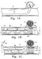
- FIG. 1Ashows a side view of a vessel with an aneurysm in its wall, wherein a vaso-occlusion coil component of an artificial occlusion kit is shown being delivered into the aneurysm.
- FIG. 1Bshows a side view of the vessel and aneurysm of FIG. 1A, wherein a retaining device assembly of the artificial occlusion kit is shown being delivered to a retaining site in the vessel adjacent the aneurysm which is substantially filled with a plurality of vaso-occlusion coils.
- FIG. 1Cshows a side view of the same vessel and aneurysm wherein the retaining device is shown electrolytically detached from a pusher, the retaining device engaging the vessel wall adjacent the entrance zone of the aneurysm, bridging across the entrance zone to form a barrier against vaso-occlusion coil migration into the vessel, and forming a lumen allowing for physiological flow through the vessel.
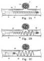
- FIGS. 2A-2Cshow in partial section, a side view of an electrolytically deployed device.
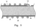
- FIG. 3shows in side view cross-section, a portion of the device shown in FIGS. 2A-2C emphasizing the section of the device employing an electrolytically erodible link.
- FIGS. 4A, 4 B, and 4 Cshow in partial cut-away, cross-section, variations of the shape of retainers made according to this invention.
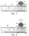
- FIG. 5shows a side view of a vessel having in its wall a wide-neck aneurysm, showing a variation of the artificial occlusion kit where the retaining device has a semi-penetrable space through which an artificial occlusion device is being introduced into an aneurysm.
- FIG. 6shows a side view of a vessel having in its wall a wide-neck aneurysm, showing a variation of the artificial occlusion kit where the retaining device has a distensible semi-penetrable space that is shown distended by a delivery catheter through which vaso-occlusion coils are being introduced into the aneurysm.
- FIG. 7shows a side view of the vessel and wide-neck aneurysm, showing a further variation of the assembly shown in FIG. 5, wherein the distensible semi-penetrable space is shown distended by an introducer wire over which vaso-occlusion coils are being coaxially advanced into the aneurysm.
- FIG. 8shows a perspective view of a further variation of retaining device wherein the retaining device is shown to be constructed of a wire wound into a helix over a core member, the helical wire and core member being formed into a secondary geometry.
- FIGS. 9A and 9Bshow in schematic cross-section anatomically shaped filler coils suitable for use in conjunction with the retention devices made according to this invention.
- the present inventionprovides a novel solution to the problem of vaso-occlusion device migration out of aneurysms or other implantation sites and into the feeding vessels that are not the target of vaso-occlusion.
- a retaining deviceis used in a novel artificial occlusion assembly to prevent migration of one or more occlusion devices from a target occlusion site by forming a barrier at the entrance zone to the target site from a feeding vessel.
- Variations of a novel implantable medical deviceare provided as the retaining device, which novel implantable medical device is included within the scope of the present invention.
- FIGS. 1A-Cshow sequential steps of a novel method of occluding a body space—here an aneurysm of a body lumen wall—using one artificial occlusion kit embodiment of the current invention.
- a retaining deviceis provided in a kit together with at least one vaso-occlusion device, which kit is also shown in use with at least one delivery catheter.
- FIG. 1Ashows the first of a plurality of vaso-occlusion coils is shown as it is being implanted into an aneurysm.
- a retaining device of a retaining device assemblyis shown being delivered to a retaining site in the body lumen adjacent the aneurysm after the aneurysm is substantially occluded with vaso-occlusion coils.
- the retaining deviceis completely implanted at the retaining site and detached from a pusher via electrolytic detachment from a pusher.
- the implanted retaining device shownforms a barrier against migration of the vaso-occlusion coils from the aneurysm and into the body lumen, while maintaining an open conduit for flow through the body lumen.
- FIG. 1Aa cut-away side view of a vessel ( 2 ) having an aneurysm ( 4 ) in its wall is shown.
- Vaso-occlusion coil ( 8 )is shown being delivered into aneurysm ( 4 ) out of the distal end of delivery catheter ( 10 ) in order to occlude the aneurysm ( 4 ).
- Vaso-occlusion coil ( 8 ) for the purposes of this inventionmay be any one of a wide variety of coils that are known in the art for occluding vessels or aneurysms.
- vaso-occlusion coil ( 8 )may be a pushable coil of the type described in U.S. Pat. No. 4,994,069.
- coil ( 8 )may be a mechanically detachable coil such as that described in U.S. Pat. No. 5,261,916 or U.S. Pat. No. 5,250,071.
- coil ( 8 )may be an electrolytically detachable coil such as that described in U.S. Pat. No. 5,122,136 or U.S. Pat. No. 5,354,294.
- vaso-occlusion coil ( 8 )may have a pre-formed secondary shape that is constrained in a stretched orientation when being delivered through delivery catheter ( 10 ) but reconfigures when delivered beyond delivery catheter ( 10 ). Such reconfiguring often includes radial expansion to a relaxed memory state having a desired, pre-determined shaped geometry.
- coil ( 8 )may have highly flexible portions that ball up from random convolutions formed while the coil flows distally during delivery, such as the coils described in pending U.S. patent application Ser. No. 08/413,970, filed Mar. 30, 1995.
- vaso-occlusion coilThe type and geometry of vaso-occlusion coil are normally chosen for the particular delivery mechanism and space-filling characteristics, as may be appropriate for a particular occlusion site.
- the disclosures of the above referenced vaso-occlusion coil documentsare herein incorporated by reference.
- the appropriate design for delivery catheter ( 10 )is defined by the ability to reach the desired occlusion site atraumatically and to efficaciously deliver the vaso-occlusion coil into the site as an occlusion implant.
- a catheterthat may be used in the present invention is described in U.S. Pat. No. Pat. 4,739,768 to Engelson, the disclosure of which is herein incorporated by reference.
- FIG. 1Bshows a retaining device ( 19 ) being delivered through delivery catheter ( 20 ) and into vessel ( 2 ) at the site of aneurysm ( 4 ).
- a plurality of vasoocclusion coils ( 12 )is also shown having been implanted into aneurysm ( 4 ) prior to delivery of the retaining device ( 19 ).
- Retaining device ( 19 )is shown as a distal segment of a retaining device assembly ( 15 ), wherein it is attached at its proximal end to a pusher ( 16 ) which is relatively more stiff than the implantable retaining device ( 19 ).
- Pusher ( 16 )is adapted for advancing the retaining device percutaneously through the delivery catheter ( 20 ), even when in tortuous bends of the vasculature, into remote internal body spaces for occlusion.
- retaining device ( 19 ) and pusher ( 16 )are shown to be coupled or attached via a joint or link ( 17 ).
- retaining device ( 19 ) and pusher ( 16 )can be either electrolytically detachable at link ( 17 ) or mechanically detachable at link ( 17 ).
- link ( 17 )is electrolytically dissolvable when current is applied thereto. Electrolytic detachment mechanisms of the types described in U.S. Pat. No. 5,122,136 or U.S. Pat. No. 5,354,295 may be suitable.
- pusher ( 16 ) and retaining device ( 19 )are mechanically detachably engaged at link ( 17 ).
- the mechanical detachment mechanisms of the types described in U.S. Pat. No. 5,261,916 or U.S. Pat. No. 5,250,071may be suitable.
- the disclosures of these above referenced electrolytically and mechanically detachable coil disclosuresare herein incorporated by reference.
- a retaining device to prevent migration of vaso-occlusion devices from an occlusion siteneed not be limited to use with a “detachable” pusher-retaining device mechanism as is shown in retaining device assembly ( 15 ). It may be equally efficacious, and perhaps even preferred in a given circumstance, to use separate, non-attached retaining device and pusher without the need for a detachable link such as link ( 17 ).
- pusherssuch as the type described in U.S. Pat. No. 4,994,069 to Ritchart et al. may be satisfactory.
- the distal end of the pushercan be advanced axially within a delivery catheter lumen to abut a proximal end of the retaining device, also disposed within the delivery lumen. With the distal pusher end in confronting engagement with the retaining device proximal end, further advancement of the pusher by the user will effectively push the retaining device distally through the lumen, out of the delivery catheter from a distal port thereof, and into a vessel site adjacent a body space where occlusion devices are deployed.
- retaining device ( 19 )has a memory in the form of a pre-determined, shaped, secondary geometry.
- Retaining device ( 19 )is shown to have a first shape with a first outer diameter “A” where it is positioned within delivery catheter ( 20 ).
- the delivery lumen ( 22 )which ends distally in distal delivery port ( 23 ), radially constrains the retaining device such that the first outer diameter is defined by the delivery lumen ( 22 ) inner diameter.
- retaining device ( 19 )When released from a radially constraining condition, retaining device ( 19 ) also forms a second shape with a second outer diameter greater than the first outer diameter “A.” and sufficient to engage the vessel wall.
- retaining device ( 19 )is shown extending beyond the distal delivery port of the delivery lumen ( 22 ) where it is radially artificially unconstrained and expanded to an outer diameter “B” larger than the first diameter “A,” engaging the lumen wall at the retaining site adjacent the aneurysm.
- the completely relaxed, unconstrained second outer diameter of the retaining devicemay be slightly greater than the diameter of the vessel. This may be necessary in order to maintain accurate placement of the retaining device in the vessel lumen at the aneurysm site.
- the purpose of the retaining deviceis merely to form a barrier at the entrance zone of the aneurysm to prevent occlusion coil migration. Unnecessary trauma to the vessel wall, such as from oversizing or coil designs that are too stiff to perform the stated purpose should be avoided.
- Retaining device ( 19 )is shown in FIG. 1B to have a helical geometry.
- retaining device ( 19 )is a metal wire that is wound into a primary helix, shown in FIG. 1B having a primary helix diameter “C”.
- This primary helixis preferably pre-formed into a secondary geometry that, as shown for this embodiment, is also in the form of a secondary helix. Therefore, the first and second shapes and corresponding first and second outer diameters that the retaining device takes when being delivered to and implanted in the vessel, respectively, are defined by the secondary geometry of the retaining device. These shapes are formed about a longitudinal axis, shown in FIG. 1B at “L,” and their respective outer diameters are defined on a radial plane perpendicular to that axis.
- Retaining device ( 19 )is also shown in FIG. 1B to form a lumen ( 30 ).
- lumen ( 30 )is defined by the simple helical shape of the retaining device's secondary geometry and extends along the longitudinal axis “L” of that helix. It is contemplated that first and second shapes other than a simple helix may still fall within the scope of the present invention.
- the purpose of the retaining deviceis to form a barrier at the entrance zone to the body space being artificially occluded by occlusion devices. Occlusion of the body lumen adjacent to the occlusion site is to be avoided in the use of the present invention. It is therefore an important aspect of the present invention that there be a physiologically acceptable through-lumen formed by the retaining device when implanted into the body lumen.
- delivery catheter ( 10 )may be the same catheter as that used for delivering the occlusion devices, such as delivery catheter ( 10 ) in FIG. 1 A.
- the two delivery cathetersmay in certain circumstances have different required characteristics for delivering the occlusion devices and retaining devices, respectively.
- a desired tip shape for delivering the occlusion devices into an aneurysm radially at the vessel wallmay be different than the tip shape appropriate for delivering the retaining device transversely into the vessel lumen adjacent the aneurysm.
- the retaining device and the occluding devicesare characteristically of different designs, since one's function is to substantially space fill and the other's is to form a barrier at the aneurysm and also to keep the vessel lumen open.
- the delivery catheters for the two designsmay require different delivery lumen diameters, material construction, etc. as may be appropriate according to one of ordinary skill.
- a delivery wiremay provide a coaxial rail over which a retaining device may be advanced such as by a pusher located proximally of the retaining device.
- the retaining devicemay have a lumen that coaxially tracks the delivery wire, the delivery wire providing radial constraint on the retaining device to form the first radially constrained shape. Advancing the retaining device distally past the end of the delivery wire releases the radial constraint and allows the retaining device to expand to a second shape.
- a further retaining device variationmay be delivered upon and expanded by a balloon on the distal end of a balloon catheter.
- the retaining deviceis provided for delivery to the retaining site while it is formed in its first shape coaxially engaged over a balloon in a deflated state.
- inflation of the balloonradially expands the retaining device into a second shape having an outer diameter sufficient to engage the vessel wall and which forms a barrier across the entrance zone to an aneurysm.
- Subsequent deflation and withdrawal of the balloonleaves the radially expanded retaining device implanted at the retaining site, which retaining device forms a lumen where the expanded balloon once was.
- FIG. 1Ca particular retaining device variation is shown detached at the retaining site in vessel ( 2 ) that is adjacent to a body space to be occluded, here aneurysm ( 4 ).
- Retaining device ( 19 )is shown having a shape that is expanded along its length to a diameter sufficient to engage the vessel wall at regions adjacent an entrance zone ( 6 ) to aneurysm ( 4 ).
- Retaining device ( 19 )also bridges across entrance zone ( 6 ) and forms a barrier against any of the plurality of vaso-occlusion devices ( 12 ) from migrating out of the aneurysm and into vessel ( 2 ).
- retaining device ( 19 )has been detached from pusher ( 16 ) by means of electrolytic or erosive severing of link ( 17 ).
- electrolytic detachmentmay occur via the systems and methods as described in U.S. Pat. No. 5,122,136; U.S. Pat. No. 5,354,294; or co-pending U.S. patent application Ser. No. 08/499,525, filed on Jul. 7, 1995, as may be apparent to one of ordinary skill in the art. The disclosures of these documents have previously been incorporated by reference.
- the retaining device of the current inventionis not an occlusion device and must provide a through-lumen for flow when implanted into a vessel lumen (in fact the opposite function of the previously disclosed electrolytically detachable occlusion devices).
- power source “E”is electrically coupled to electrolytically severable link ( 17 ).
- An electrode ( 40 )is also shown schematically in FIG. 1C, where it is also shown electrically coupled with power source “E.”
- Electrode ( 40 )may be a skin electrode having a relatively high surface area in contact with the patient when compared to that of link ( 17 ).
- retaining device assembly ( 15 )is disposed within the body such that link ( 17 ) is in patient contact. Since electrode ( 40 ) is in skin contact with the patient, a circuit may be formed wherein direct current from power source “E” may pass through link ( 17 ), quickly dissipate at a low current density through the patient as an electrical conductor, and through electrode ( 40 ) back to power source “E.” This current serves to dissolve link ( 17 ) until retaining device ( 19 ) is detached from pusher ( 16 ).
- Power source “E”may additionally superimpose an alternating current over the direct current signal, which alternating current signal may be sensed by a sensing circuit (not shown) as an indicator of the progression of electrolytic detachment at link ( 17 ). Additionally, a control circuit (not shown) may be used to alter the output power signal or shut the signal off upon the sensing of a critical parameter by the sensing circuit, such as the sensing of a particular change in the alternating current component of the output signal.
- Such monitoring and feedback control of electrolytic detachmentmay employ the apparatus and methods as described in co-pending U.S. patent application Ser. No. 08/205,512 filed Mar. 3, 1994 (previously discussed).
- the electrolytic detachmentallows for minimal engaging structure at the detachable coupling end of the implantable medical device (as compared to mechanically detachable designs which may require clasps, enlarged balls, etc. on the end of the implant coil). It is believed, therefore, that electrolytic dissolution of link ( 17 ) thus provides an optimal solution for implanting an implantable medical device for use as an occlusion coil retaining device.
- FIGS. 2A-2Cdepict a different variation of the artificial occlusion kit.
- a vaso-occlusive coil ( 12 )is maintained in an aneurysm ( 4 ) emanating from an artery ( 2 ) by a retaining device assembly ( 30 ) which is delivered to the site of the aneurysm ( 4 ) by guidewire.
- the retaining device assembly ( 30 )is maintained in a radially compressed fashion by the use of a pair of electrolytic links ( 32 , 33 ). As will be shown below in discussion of FIG. 3 .
- FIG. 2Ashows the retaining device assembly ( 30 ) closely coiled to the body of the core or guidewire ( 31 ).
- the retaining device assembly ( 30 )is of a material or has been treated in such a way that the “normal” or relaxed condition of the retaining device assembly ( 30 ) is as shown in FIG. 2C.
- a single wire deviceis depicted in FIGS. 2A, 2 B and 2 C, but a helically wound coil is certainly suitable as well.
- the retaining device assembly ( 30 )must be either insulated in its entirety from the surrounding fluid (via, e.g., a plastic coating or the like) or of a material which is more noble or higher in the electromotive series than are the links ( 32 ) and ( 33 ) shown in the drawing. Further, the guidewire ( 31 ) distal tip coil ( 34 ) and the like must be insulated as well. As was discussed above in some detail, this detachment link operates via the electrolytic erosion of the bare links found at ( 32 ) and ( 33 ). In the sequence shown in FIGS. 2A, 2 B and 2 C, the link found at ( 33 ) is smaller in diameter than is the link found at ( 32 ).
- link ( 33 )erodes to a point where it breaks earlier than does the link at ( 32 ) simply because of the smaller diameter of link ( 33 ).
- link ( 32 )continues to electrolytically erode as time passes. After the second joint ( 32 ) has broken and the retaining device assembly ( 30 ) has expanded as shown in FIG. 2C, the core wire and its allied parts ( 31 ) are removed.
- FIG. 3shows a portion of the core wire ( 31 ) with the retaining device assembly ( 30 ) closely disposed on its outer surface as would be the case in FIG. 2 A.
- the inner core ( 36 )is covered by an insulating layer ( 37 ) of, e.g., a polytetrafluoroethylene.
- the displayed link ( 33 )is in an electrical contact with the core ( 36 ) and holds the retaining device assembly ( 30 ) in close contact with the core wire assembly ( 31 ). It is this link ( 33 ) which erodes to release the retaining device assembly ( 30 ).
- FIG. 4Ashows a variation of the overall shape of a retaining device assembly ( 38 ) made in keeping with this invention.
- the retaining device assembly ( 38 )has two end regions ( 39 ) which have a diameter when deployed which approximates (or is slightly larger than) the inner diameter of the vessel lumen into which it is placed.
- the retaining device assembly ( 38 )has a center section ( 41 ) which has a smaller overall radius than the two end sections ( 39 ).
- the smaller mid-section ( 41 )has a variety of benefits. For instance, it does not press on the vessel or on the coil ( 12 ) within aneurysm ( 4 ).
- the retaining device assembly ( 38 ) made in this formis easier to move should it be mal-placed in the human body. It has smaller regions in contact with the vessel lumen.
- the shape of the deviceis not particularly critical in many of these variations.
- the shape of retaining device assembly ( 38 )must be sufficiently appropriate for it to maintain the coil ( 12 ) within aneurysm ( 14 ). It must have sufficient radial springiness to allow its shape to be maintained in the lumen of the body vessel described herein.
- FIGS. 4B and 4COne very effective and highly desirable method of preventing the retainer from turning in the vessel lumen during deployment is found in FIGS. 4B and 4C.
- the retaining device assembly( 43 in FIG. 4B and 46 in FIG. 4 C), incorporates a leading or distal helix section which has a deployed diameter which is smaller than the diameter of the vessel lumen.
- the retaining device assembly ( 43 )is first deployed to the right (or distal end) of the Figure.
- the proximal end of the retaining device assemblyhas a diameter ( 44 ) which is equal to or larger than the diameter of the vessel lumen.
- the earlier deployed distal endhas a smaller diameter ( 45 ).
- the smaller diameter distal sectionexits the catheter end and simply forms a tubular cylinder within the lumen of the vessel.
- the distal end of the retainer device assembly ( 43 )conceptually forms an indexing end and aligns the remainder of the retainer device assembly ( 43 ) with the lumen for further deployment.
- the distal diameter ( 45 )should not be appreciably smaller than the lumen diameter ( 44 ) lest the retaining device assembly ( 43 ) begin to block blood flow. We believe that the distal diameter ( 45 ) should be at least 75% of the lumen diameter ( 44 ).
- proximal diameter portion of the retaining device assembly ( 43 )does not completely cover the mouth ( 6 ) of the aneurysm ( 4 ) in the Figures. This is not critical but the is an option in this variation.
- FIG. 4Cshows a similar variation of the invention in which the distal portion of the retaining device assembly ( 46 ) is stepped and has two short sections of respectively smaller diameters ( 48 , 49 ).
- a further artificial occlusion kit embodimentallows for implantation of the retaining device prior to implantation of occlusion devices, an embodiment particularly useful in “wide-neck” aneurysms.
- occlusion devicesmay not be implantable at all into the aneurysm without immediate migration into a flowing vessel prior to insertion of a retaining device at the entrance zone.
- This embodimentsolves this problem by providing semi-penetrable spaces in the retaining device at the entrance zone from the body lumen to the adjacent body space to be occluded.
- the retaining device in the variations of this embodimentmay be a helically wound member, wherein the semi-penetrable space for occlusion device insertion is provided by the space between adjacent windings of the helix.
- the helically wound member that forms the retaining deviceis a metal wire wound into a primary helix which is further wound into a secondary helix. In this mode, windings of the secondary helix form the semi-penetrable space for occlusion device insertion.
- the predetermined, semi-penetrable space ( 60 ) of retaining device ( 69 )is defined by the space between adjacent helical windings ( 58 ) and ( 59 ).
- This semi-penetrable space ( 60 )is equal to or greater in diameter than occlusion device ( 62 ) when it is being introduced into aneurysm ( 54 ).
- semi-penetrable space ( 60 )is less than the diameter of occlusion device ( 62 ) after it is in the aneurysm.
- the spacing provided by the retaining deviceallows the introduction of occlusion devices into the aneurysm but does not allow significant migration of occlusion devices, once implanted, back into the adjacent vessel lumen ( 53 ).
- the occlusion device ( 62 )is radially constrained to a first shape having a first outer diameter when within the delivery lumen of delivery catheter ( 70 ).
- the delivery catheter distal endis abutting the inner surface of the retaining device ( 69 ).
- the occlusion device ( 62 )is then advanced out the distal end of the delivery catheter ( 70 ) and through the space in the retaining device ( 69 ), where it is then radially artificially unconstrained.
- the occlusion device ( 62 )takes on a second shape having a second outer diameter that prevents it from migrating back through the semi-penetrable space and into the body lumen ( 53 ).
- the semi-penetrable spaces of the retaining deviceare distensible. This distensibility enhances the semi-penetrability of the spaces. More specifically, occlusion devices may be introduced through such spaces when an applied force distends open the spaces. Once the occlusion devices are implanted into the occlusion site, however, passive migration of the devices back through the spaces does not provide the requisite force to distend open these spaces—the passive migration is thus prevented.
- a particular occlusion devicemay be used in conjunction with a retaining device, and be of such construction and dimension that it may be advanced unaided through the spaces provided in the retaining device.
- detachable occlusion devicessuch as those described in U.S. Pat. No. 5,122,136 or U.S. Pat. No. 5,354,295 may be constructed with sufficient pushability to be advanced between adjacent coil winds of the retaining device and into the aneurysm sac. They may thereafter be detached within the aneurysm for occlusion.
- FIG. 6Another aspect of this variation is shown in FIG. 6 .
- retaining device ( 119 )is shown implanted into vessel ( 102 ) such that it radially engages the vessel wall adjacent to entrance zone ( 106 ) to wide-neck aneurysm ( 104 ) and bridges across entrance zone ( 106 ).
- the helical shape of retaining device ( 119 )is shown to have a pre-determined spacing which may be spread when adjacent helical windings are forced apart.
- delivery catheter ( 110 )is advanced through the retaining device and into the entrance zone ( 106 ) of the aneurysm ( 104 ).
- delivery catheter ( 110 )has a tip ( 111 ) which is tapered and dimensioned such that adjacent helical windings of retaining device ( 119 ) are forced apart when delivery catheter ( 110 ) is forced radially against the retaining device ( 119 ) from its inner lumen ( 130 ) and toward the entrance zone ( 106 ).
- delivery catheter ( 110 )may, for example, have a pre-shaped bend in the distal delivery catheter region ending in tip ( 111 ). This shape may aid in the advancement of the delivery catheter through the branching vasculature, or may also be sufficiently straightened coaxially over a guidewire to avoid proximal vessel trauma while tracking to the site.
- an introducer wire ( 140 )may be forced through spaces provided in the retaining device, such as between adjacent winds of a helically shaped retaining device as shown in FIG. 7 .
- a delivery cathetersuch as delivery catheter ( 110 ) (shown in FIG. 6) may thereafter be advanced coaxially over the introducer wire ( 140 ) and into the entrance zone of the wide-neck aneurysm.
- delivery catheter ( 120 )is not shown to be advanced into entrance zone ( 106 ) or aneurysm ( 104 ), but rather is advanced merely to abut the inner diameter of the helical windings forming retaining device ( 119 ).
- Vaso-occlusion coil ( 108 )is shown being advanced coaxially over introducer wire ( 140 ) while advancing through delivery catheter ( 120 ), through adjacent windings of helical retaining device ( 119 ), and ultimately off the distal end of introducer wire ( 140 ) and into the sac of aneurysm ( 104 ).
- vaso-occlusion coil ( 108 )may occur, for example, by coaxially advancing a pusher member, located proximally of vaso-occlusion coil ( 108 ), in the distal direction against a proximal end of vaso-occlusion coil.
- introducer wire ( 140 )may also be shapeable such that it is adapted for tracking to the retaining site adjacent the aneurysm, as well as for advancing through the spaces in the retaining device barrier at the aneurysm entrance zone.
- Conventional guidewires of the type known in the artmay perform sufficiently as introducer wire ( 140 ) in a particular case.
- the present inventionfurther contemplates obvious alterations to known wire designs in order to function with the individual features of a particular retaining device design, as may be apparent to one of ordinary skill.
- Such particularized retaining device features that may dictate introducer wire design parameters, for example,may be the diameter and degree of distensibility of the semi-permeable space.
- the implantable medical device that functions as a retaining device in the novel artificial occlusion kithas a particular construction that includes a wire ( 202 ) wound into a primary helix over an inner core member ( 204 ).
- the inner core member ( 204 ) and primary wire helixare also wound into a secondary geometry, and are soldered or welded at both of two ends ( 210 ) and ( 212 ).
- the secured ends ( 210 ) and ( 212 )serve to secure the “wire over core” composite relationship and also provide smooth ends for safety considerations in this implantable device.
- the inner core member ( 204 )is a metal mandrel, and more preferably is a superelastic alloy of nickel-titanium.
- the inner core member ( 204 )is constructed of a nickel-titanium alloy and has an outer diameter from 0.003′′ to 0.006′′.
- the helically wound wire ( 202 ) in this preferred variationmay be a radiopaque metal, such as platinum, gold, or tungsten, and has an outer diameter in the range of 0.001′′ to 0.006′′.
- the coilmay have 0-100% spacing.
- wire ( 202 )is wound at a pitch of 0.001′′ to 0.008′′ with 0-100% spacing. For instance, a coil made with 0.003′′ wire with 0.006′′ pitch has 100% spacing; a coil with 0.003′′ wire and 0.006′′ pitch has 0% spacing.
- wire ( 202 )is secured to the inner core member ( 204 ) using the following process: the coil is secured to the inner core member at least two or several locations, preferably at both ends.
- One method for joining the componentsinvolves resistance welding or a similar such process. Soldering or brazing is similarly useful in joining the metals.
- the inner core member ( 204 )is chosen such as to provide the requisite shape memory and stiffness.
- This inner core membermay not by itself provide optimal radiopacity, since it is not chosen for that purpose.
- the requisite radiopacity of the devicemay instead be provided by the outer wound coil ( 202 ), which might not provide optimal stiffness or material memory if it were only available alone in the device. It is believed that the combined features of this “wire over core” design may optimally adapt prior known implantable coil technologies to meet the particular structural needs of a retaining device in the current invention.
- the elongate retaining devicebe flexible along its length so that it can be implanted into lumens having bends.
- too much flexibilitymay correspond to irregular and random conformations of the coil when implanted in-vivo, which may produce an occlusive effect.
- a primary helical coil wound into a secondary helixwithout more, may be too flexible to effectively engage a vessel wall along the requisite length to form a barrier against occlusion device migration.
- the addition of the mandrel in what would otherwise be the primary helix lumenprovides a stiffening structure that still allows for a certain controlled flexibility of the secondary helical shape.
- prior vaso-occlusion coilsrequire substantial space filling for effective cross-sectional blockage of a body lumen, for example.
- only a minimal portion of the devicemay be required to actually radially engage a vessel wall for primarily the purpose of anchoring the device at the occlusion site.
- This means only a small portion of the coilmay need to reconfigure from a first constrained diameter during delivery to a second diameter at least approximating the lumenal wall diameter when delivered. It may be acceptable, even desirable, for such occlusion coils to have portions not so significantly altered in their cross-sectional diameter when they are delivered at an implantation site, so long as their shape presents an occlusion to flow.
- the present inventive retaining devicemust take on a shape at the retaining site that has sufficient outer diameter along a sufficient length of the device to form an effective barrier across the aneurysm entrance zone at the vessel wall. Impinging into the lumen's cross-section is generally undesirable.
- the reconfiguration to this expanded shape from a first radially constrained shape during deliverymay correspond to a higher degree of requisite material memory than is possible from a simple fine wire wound into the primary and secondary helix shapes as previously disclosed.
- An inner core mandrelmay offer the structure necessary to provide such memory.
- the wire forming the primary helical coreis wound much tighter than a similar wire might be wound to optimally form an occlusion device. It is believed that coil stiffness may be controlled by adjusting the outer diameter of the primary coil helix (e.g. tightness of winding) to which a given wire is wound. It is believed that, by providing one preferred retaining device may comprise a wire wound very tightly into a primary helix that has also a secondary shape.
- One preferred application of this “tightly wound” variationcomprises a platinum wire of 0.005′′ outer diameter wound over a 0.009′′ mandrel.
- common known occlusion coils for occluding aneurysmsis constructed a 0.005′′ wire wound over a 0.011′′ mandrel.
- a wire having an outer diameter of 0.003′′may be wound over a mandrel having an outer diameter of 0.007′′.
- the wireis thereafter annealed in the wound shape to form a primary coil of predetermined dimensions.
- a secondary shapemay then be imparted to the primary coil, which secondary shape may also be a helical coil.
- the ultimate goal of the particular artificial occlusion kits, novel components thereof, and related methods described aboveis to occlude aneurysms having entrance zones or necks that are of such width and geometry that conventional techniques would result in unwanted migration of occlusion devices from the aneurysm and into the adjacent vessel.
- the assemblies, components, and methods of the present inventionthat were conceived of in order to meet this need may provide additional benefits in other medical treatments.
- the inventioncontemplates retaining device designs that meet the general requirements of the novel artificial occlusion kit but vary from the specific variations just described.
- the artificial occlusion kit embodiments and variationshave been described specifically as applied to aneurysms in vessel walls.
- other occlusion sites adjacent to and in fluid communication with body lumensmay present similar concerns as to migration of occlusion devices from an occlusion site and into an adjacent lumen.
- a vessel that branches off of a feeding vesselmay be a body space to be occluded and the feeding vessel at a region adjacent to the branching vessel may be a desired retaining site.
- the present inventioncontemplates use of the apparatus embodiments described in such body spaces and lumens in addition to aneurysm sites in vessels.
- the inventionalso broadly contemplates a retaining device structure that is expandable at a retaining site of a body lumen to form a barrier against migration of at least one occlusion device through an entrance zone between an occlusion site and an adjacent lumen, and that also provides a lumen for flow through the body lumen at the retaining site.
- a retaining device structurethat is expandable at a retaining site of a body lumen to form a barrier against migration of at least one occlusion device through an entrance zone between an occlusion site and an adjacent lumen, and that also provides a lumen for flow through the body lumen at the retaining site.
- Exampleshave been provided in the form of shape memory coils delivered through radially confining delivery sheaths or over delivery wires, in addition to an alternative balloon expandable retaining device embodiment.
- Various specific retaining device designsthat meet the broad requirements provided, beyond the particular variations provided, are within the scope of this invention.
- At least one novel electrolytically detachable implantable medical devicehas been conceived of for use as a retaining device in the artificial occlusion kit.
- This novel implantable medical devicemay have useful medical applications in addition to retaining artificial occlusion devices.
- the scope of this aspect of the invention, while intimately pertaining to an artificial occlusion kit,should not be limited to the kit embodiments described for artificial occlusion.
Landscapes
- Health & Medical Sciences (AREA)
- Life Sciences & Earth Sciences (AREA)
- Surgery (AREA)
- Engineering & Computer Science (AREA)
- Biomedical Technology (AREA)
- Animal Behavior & Ethology (AREA)
- Veterinary Medicine (AREA)
- Vascular Medicine (AREA)
- Public Health (AREA)
- Heart & Thoracic Surgery (AREA)
- General Health & Medical Sciences (AREA)
- Molecular Biology (AREA)
- Medical Informatics (AREA)
- Nuclear Medicine, Radiotherapy & Molecular Imaging (AREA)
- Reproductive Health (AREA)
- Cardiology (AREA)
- Oral & Maxillofacial Surgery (AREA)
- Transplantation (AREA)
- Neurosurgery (AREA)
- Surgical Instruments (AREA)
- Prostheses (AREA)
- Media Introduction/Drainage Providing Device (AREA)
- Materials For Medical Uses (AREA)
Abstract
Description
Claims (11)
Priority Applications (1)
| Application Number | Priority Date | Filing Date | Title |
|---|---|---|---|
| US09/699,267US6344041B1 (en) | 1996-07-26 | 2001-10-26 | Aneurysm closure device assembly |
Applications Claiming Priority (3)
| Application Number | Priority Date | Filing Date | Title |
|---|---|---|---|
| US08/690,183US5980514A (en) | 1996-07-26 | 1996-07-26 | Aneurysm closure device assembly |
| US09/298,357US6168592B1 (en) | 1996-07-26 | 1999-04-23 | Aneurysm closure device assembly |
| US09/699,267US6344041B1 (en) | 1996-07-26 | 2001-10-26 | Aneurysm closure device assembly |
Related Parent Applications (1)
| Application Number | Title | Priority Date | Filing Date |
|---|---|---|---|
| US09/298,357ContinuationUS6168592B1 (en) | 1996-07-26 | 1999-04-23 | Aneurysm closure device assembly |
Publications (1)
| Publication Number | Publication Date |
|---|---|
| US6344041B1true US6344041B1 (en) | 2002-02-05 |
Family
ID=24771444
Family Applications (3)
| Application Number | Title | Priority Date | Filing Date |
|---|---|---|---|
| US08/690,183Expired - LifetimeUS5980514A (en) | 1996-07-26 | 1996-07-26 | Aneurysm closure device assembly |
| US09/298,357Expired - LifetimeUS6168592B1 (en) | 1996-07-26 | 1999-04-23 | Aneurysm closure device assembly |
| US09/699,267Expired - LifetimeUS6344041B1 (en) | 1996-07-26 | 2001-10-26 | Aneurysm closure device assembly |
Family Applications Before (2)
| Application Number | Title | Priority Date | Filing Date |
|---|---|---|---|
| US08/690,183Expired - LifetimeUS5980514A (en) | 1996-07-26 | 1996-07-26 | Aneurysm closure device assembly |
| US09/298,357Expired - LifetimeUS6168592B1 (en) | 1996-07-26 | 1999-04-23 | Aneurysm closure device assembly |
Country Status (11)
| Country | Link |
|---|---|
| US (3) | US5980514A (en) |
| EP (1) | EP0820726B1 (en) |
| JP (2) | JP3205526B2 (en) |
| KR (1) | KR980008179A (en) |
| AT (1) | ATE249171T1 (en) |
| AU (1) | AU709076B2 (en) |
| CA (1) | CA2211512C (en) |
| DE (1) | DE69724712T2 (en) |
| ES (1) | ES2202553T3 (en) |
| NO (1) | NO973373L (en) |
| TW (1) | TW359601B (en) |
Cited By (151)
| Publication number | Priority date | Publication date | Assignee | Title |
|---|---|---|---|---|
| US20020161342A1 (en)* | 2001-03-27 | 2002-10-31 | Patrick Rivelli | Device for multi-modal treatment of vascular lesions |
| US20030181856A1 (en)* | 2002-02-01 | 2003-09-25 | Goldman Robert J. | Multi-function catheter and use thereof |
| US20030187473A1 (en)* | 2002-03-27 | 2003-10-02 | Alejandro Berenstein | Expandable body cavity liner device |
| US20030216807A1 (en)* | 2002-05-16 | 2003-11-20 | Jones Donald K. | Intravascular stent device |
| US20040034378A1 (en)* | 2001-04-10 | 2004-02-19 | Hermann Monstadt | Device for implanting occlusion spirals |
| US20040116959A1 (en)* | 2001-06-18 | 2004-06-17 | Rex Medical | Vein filter |
| US20040133222A1 (en)* | 2003-01-07 | 2004-07-08 | Scimed Life Systems, Inc. | Occlusive cinching devices and methods of use |
| US20040158306A1 (en)* | 2001-06-14 | 2004-08-12 | Vladimir Mitelberg | Intravascular stent device |
| US6783538B2 (en) | 2001-06-18 | 2004-08-31 | Rex Medical, L.P | Removable vein filter |
| US6793665B2 (en) | 2001-06-18 | 2004-09-21 | Rex Medical, L.P. | Multiple access vein filter |
| US20040186464A1 (en)* | 2003-03-20 | 2004-09-23 | Scimed Life Systems, Inc. | Piezoelectric vascular implant release device |
| US20040193179A1 (en)* | 2003-03-26 | 2004-09-30 | Cardiomind, Inc. | Balloon catheter lumen based stent delivery systems |
| US20040199175A1 (en)* | 2003-04-03 | 2004-10-07 | Scimed Life Systems, Inc. | Flexible embolic device delivery system |
| US20050004596A1 (en)* | 2001-06-18 | 2005-01-06 | Mcguckin James F. | Vein filter |
| WO2004045393A3 (en)* | 2002-11-20 | 2005-01-06 | Fogarty Thomas J | Devices and methods for treatment of vascular aneurysms |
| US20050015110A1 (en)* | 2003-07-18 | 2005-01-20 | Fogarty Thomas J. | Embolization device and a method of using the same |
| US20050015111A1 (en)* | 2001-06-18 | 2005-01-20 | Mcguckin James F. | Vein filter |
| US20050021129A1 (en)* | 2000-12-28 | 2005-01-27 | Pelton Brian Lee | Thermoelastic and superelastic Ni-Ti-W alloy |
| US20050021072A1 (en)* | 2003-07-25 | 2005-01-27 | Scimed Life Systems, Inc. | Method and system for delivering an implant utilizing a lumen reducing member |
| US20050165442A1 (en)* | 2004-01-22 | 2005-07-28 | Thinnes John H.Jr. | Vein filter |
| US20050165441A1 (en)* | 2004-01-22 | 2005-07-28 | Mcguckin James F.Jr. | Vein filter |
| US20050195789A1 (en)* | 2004-03-02 | 2005-09-08 | Nokia Corporation | Preventing an incorrect synchronization between a received code-modulated signal and a replica code |
| US20050209675A1 (en)* | 2004-03-02 | 2005-09-22 | Ton Dai T | Corewire actuated delivery system with fixed distal stent-carrying extension |
| US20050209672A1 (en)* | 2004-03-02 | 2005-09-22 | Cardiomind, Inc. | Sliding restraint stent delivery systems |
| US20050209671A1 (en)* | 2004-03-02 | 2005-09-22 | Cardiomind, Inc. | Corewire actuated delivery system with fixed distal stent-carrying extension |
| US20050209670A1 (en)* | 2004-03-02 | 2005-09-22 | Cardiomind, Inc. | Stent delivery system with diameter adaptive restraint |
| US6951571B1 (en) | 2004-09-30 | 2005-10-04 | Rohit Srivastava | Valve implanting device |
| US20050267407A1 (en)* | 2002-02-01 | 2005-12-01 | Vascular Designs, Inc. | Multi-function catheter and use thereof |
| US20060064151A1 (en)* | 2004-09-22 | 2006-03-23 | Guterman Lee R | Cranial aneurysm treatment arrangement |
| US20060085057A1 (en)* | 2004-10-14 | 2006-04-20 | Cardiomind | Delivery guide member based stent anti-jumping technologies |
| US20060111771A1 (en)* | 2003-03-26 | 2006-05-25 | Ton Dai T | Twist-down implant delivery technologies |
| US20060200190A1 (en)* | 2005-03-02 | 2006-09-07 | Lorenzo Juan A | Embolic coil with twisted wire |
| US20060206200A1 (en)* | 2004-05-25 | 2006-09-14 | Chestnut Medical Technologies, Inc. | Flexible vascular occluding device |
| US20060206201A1 (en)* | 2004-05-25 | 2006-09-14 | Chestnut Medical Technologies, Inc. | Flexible vascular occluding device |
| US20060203769A1 (en)* | 2005-03-11 | 2006-09-14 | Saholt Douglas R | Intravascular filter with centering member |
| US20060224175A1 (en)* | 2005-03-29 | 2006-10-05 | Vrba Anthony C | Methods and apparatuses for disposition of a medical device onto an elongate medical device |
| US7153323B1 (en)* | 2000-06-30 | 2006-12-26 | Boston Scientific Scimed, Inc. | Aneurysm liner with multi-segment extender |
| US20070043419A1 (en)* | 2003-03-26 | 2007-02-22 | Cardiomind, Inc. | Implant delivery technologies |
| US20070073379A1 (en)* | 2005-09-29 | 2007-03-29 | Chang Jean C | Stent delivery system |
| US20070073334A1 (en)* | 2005-09-29 | 2007-03-29 | Kamal Ramzipoor | Combined electrolytic and mechanical separation background |
| US20070083226A1 (en)* | 2005-10-12 | 2007-04-12 | Buiser Marcia S | Coil assemblies, components and methods |
| US20070088381A1 (en)* | 2004-09-27 | 2007-04-19 | Mcguckin James F Jr | Vein filter |
| US20070100418A1 (en)* | 2005-11-02 | 2007-05-03 | David Licata | Pass-through restraint electrolytic implant delivery systems |
| US20070213685A1 (en)* | 2004-01-22 | 2007-09-13 | Rex Medical | Method of removing a vein filter |
| US20070292472A1 (en)* | 2006-06-15 | 2007-12-20 | Paul Ram H | Methods, systems and devices for the delivery of endoluminal prostheses |
| US20080125855A1 (en)* | 2002-07-19 | 2008-05-29 | Hans Henkes | Medical implant having a curlable matrix structure |
| US7410482B2 (en) | 1998-09-04 | 2008-08-12 | Boston Scientific-Scimed, Inc. | Detachable aneurysm neck bridge |
| US20080208118A1 (en)* | 2002-02-01 | 2008-08-28 | Vascular Designs, Inc. | Multi-function catheter and use thereof |
| US20080221666A1 (en)* | 2006-12-15 | 2008-09-11 | Cardiomind, Inc. | Stent systems |
| US20080228215A1 (en)* | 2007-03-13 | 2008-09-18 | Micro Therapeutics, Inc. | Implant including a coil and a stretch-resistant member |
| US20080319532A1 (en)* | 2004-09-22 | 2008-12-25 | Ev3, Inc. | Medical Implant |
| US20090105748A1 (en)* | 2002-11-12 | 2009-04-23 | Thomas J. Fogarty | Embolization device and a method of using the same |
| US20090105722A1 (en)* | 2007-10-17 | 2009-04-23 | Mindframe, Inc. | Devices and methods for embolus removal during acute ischemic stroke |
| US20090125053A1 (en)* | 2007-11-12 | 2009-05-14 | Mindframe, Inc. | Aneurysm neck bridging processes with revascularization systems methods and products thereby |
| US20090192455A1 (en)* | 2008-01-07 | 2009-07-30 | David Ferrera | Novel enhanced ptna rapid exchange type of catheter system |
| WO2009103125A1 (en)* | 2008-02-20 | 2009-08-27 | Neustent Pty Ltd | A stent |
| US20090287241A1 (en)* | 2004-05-25 | 2009-11-19 | Chestnut Medical Technologies, Inc. | Methods and apparatus for luminal stenting |
| US20090287292A1 (en)* | 2008-05-13 | 2009-11-19 | Becking Frank P | Braid Implant Delivery Systems |
| US20090292297A1 (en)* | 2008-05-19 | 2009-11-26 | David Ferrere | Devices for Restoring Blood Flow and Embolus Removal During Acute Ischemic Stroke |
| US20100023105A1 (en)* | 2008-07-22 | 2010-01-28 | Micro Therapeutics, Inc. | Vascular remodeling device |
| US20100030200A1 (en)* | 2006-04-17 | 2010-02-04 | Micro Therapeutics, Inc. | System and method for mechanically positioning intravascular implants |
| US20100100106A1 (en)* | 2008-04-11 | 2010-04-22 | Mindframe, Inc. | Monorail neuro-microcatheter for delivery of medical devices to treat stroke, processes and products thereby |
| US20100131002A1 (en)* | 2008-11-24 | 2010-05-27 | Connor Robert A | Stent with a net layer to embolize and aneurysm |
| US20100151216A1 (en)* | 2007-01-08 | 2010-06-17 | High Impact Technology, L.L.C. | Stratified panel structure possessing interleaved, thin-high-density, thick-low-density core-structure stack arrangement |
| US20100160953A1 (en)* | 2008-12-10 | 2010-06-24 | Boston Scientific Scimed, Inc. | Introducer sheath for use with an embolic coil device and methods for making and using the same |
| US20100174309A1 (en)* | 2008-05-19 | 2010-07-08 | Mindframe, Inc. | Recanalization/revascularization and embolus addressing systems including expandable tip neuro-microcatheter |
| US20100256600A1 (en)* | 2009-04-04 | 2010-10-07 | Ferrera David A | Neurovascular otw pta balloon catheter and delivery system |
| US20100312270A1 (en)* | 2004-01-22 | 2010-12-09 | Rex Medical, L.P. | Vein filter |
| US20100318097A1 (en)* | 2007-10-17 | 2010-12-16 | Mindframe, Inc. | Acute stroke revascularization/recanalization systems processes and products thereby |
| US20100331948A1 (en)* | 2009-06-26 | 2010-12-30 | Cardiomind, Inc. | Implant delivery apparatus and methods with electrolytic release |
| US20110046658A1 (en)* | 2008-05-01 | 2011-02-24 | Aneuclose Llc | Aneurysm occlusion device |
| US20110060212A1 (en)* | 2008-02-22 | 2011-03-10 | Micro Therapeutics, Inc. | Methods and apparatus for flow restoration |
| US20110160760A1 (en)* | 2007-10-17 | 2011-06-30 | Mindframe, Inc. | System for providing progressive therapy for thrombus management |
| US20110166588A1 (en)* | 2010-01-04 | 2011-07-07 | Connor Robert A | Aneurysm embolization by rotational accumulation of mass |
| US20110184453A1 (en)* | 2010-01-28 | 2011-07-28 | Micro Therapeutics, Inc. | Vascular remodeling device |
| US20110184452A1 (en)* | 2010-01-28 | 2011-07-28 | Micro Therapeutics, Inc. | Vascular remodeling device |
| USRE42625E1 (en) | 1990-03-13 | 2011-08-16 | The Regents Of The University Of California | Endovascular electrolytically detachable wire and tip for the formation of thrombus in arteries, veins, aneurysms, vascular malformations and arteriovenous fistulas |
| US20110208227A1 (en)* | 2008-04-21 | 2011-08-25 | Becking Frank P | Filamentary Devices For Treatment Of Vascular Defects |
| USRE42662E1 (en) | 1990-03-13 | 2011-08-30 | The Regents Of The University Of California | Endovascular electrolytically detachable wire and tip for the formation of thrombus in arteries, veins, aneurysms, vascular malformations and arteriovenous fistulas |
| USRE42756E1 (en) | 1990-03-13 | 2011-09-27 | The Regents Of The University Of California | Endovascular electrolytically detachable wire and tip for the formation of thrombus in arteries, veins, aneurysms, vascular malformations and arteriovenous fistulas |
| US8062326B2 (en) | 2004-01-22 | 2011-11-22 | Rex Medical, L.P. | Vein filter |
| US8147534B2 (en) | 2005-05-25 | 2012-04-03 | Tyco Healthcare Group Lp | System and method for delivering and deploying an occluding device within a vessel |
| US8162972B2 (en) | 2004-01-22 | 2012-04-24 | Rex Medical, Lp | Vein filter |
| US8267985B2 (en) | 2005-05-25 | 2012-09-18 | Tyco Healthcare Group Lp | System and method for delivering and deploying an occluding device within a vessel |
| US8273101B2 (en) | 2005-05-25 | 2012-09-25 | Tyco Healthcare Group Lp | System and method for delivering and deploying an occluding device within a vessel |
| US20120271409A1 (en)* | 2011-04-25 | 2012-10-25 | Medtronic Vascular, Inc. | Helical Radiopaque Marker |
| WO2012178089A1 (en) | 2011-06-22 | 2012-12-27 | Nfocus Neuromedical, Inc. | Trimmed-end aneurysm embolization devices |
| US8394119B2 (en) | 2006-02-22 | 2013-03-12 | Covidien Lp | Stents having radiopaque mesh |
| US8398701B2 (en) | 2004-05-25 | 2013-03-19 | Covidien Lp | Flexible vascular occluding device |
| US8425548B2 (en) | 2010-07-01 | 2013-04-23 | Aneaclose LLC | Occluding member expansion and then stent expansion for aneurysm treatment |
| US8425537B2 (en)* | 2006-07-31 | 2013-04-23 | Codman & Shurtleff, Inc. | Method of using interventional medical device system having an elongation retarding portion |
| US20130103074A1 (en)* | 2007-12-11 | 2013-04-25 | Cornell University | Method and apparatus for restricting flow through an opening in the side wall of a body lumen, and/or for reinforcing a weakness in the side wall of a body lumen, while still maintaining substantially normal flow through the body lumen |
| WO2013109309A1 (en)* | 2012-01-17 | 2013-07-25 | Novita Therapeutics, Llc | Expandable body device and method of use |
| US8500774B2 (en) | 2004-01-22 | 2013-08-06 | Rex Medical, L.P. | Vein filter |
| US8585713B2 (en) | 2007-10-17 | 2013-11-19 | Covidien Lp | Expandable tip assembly for thrombus management |
| US8777979B2 (en) | 2006-04-17 | 2014-07-15 | Covidien Lp | System and method for mechanically positioning intravascular implants |
| US8801747B2 (en) | 2007-03-13 | 2014-08-12 | Covidien Lp | Implant, a mandrel, and a method of forming an implant |
| US8821528B2 (en) | 2001-06-18 | 2014-09-02 | Rex Medical, L.P. | Removable vein filter |
| US20150032145A1 (en)* | 2007-12-11 | 2015-01-29 | Cornell University | Method and apparatus for restricting flow through an opening in the side wall of a body lumen, and/or for reinforcing a weakness in the side wall of a body lumen, while still maintaining substantially normal flow through the body lumen |
| US8956475B2 (en) | 2007-12-11 | 2015-02-17 | Howard Riina | Method and apparatus for restricting flow through an opening in the side wall of a body lumen, and/or for reinforcing a weakness in the side wall of a body lumen, while still maintaining substantially normal flow through the body lumen |
| US9039749B2 (en) | 2010-10-01 | 2015-05-26 | Covidien Lp | Methods and apparatuses for flow restoration and implanting members in the human body |
| US9060886B2 (en) | 2011-09-29 | 2015-06-23 | Covidien Lp | Vascular remodeling device |
| US9089332B2 (en) | 2011-03-25 | 2015-07-28 | Covidien Lp | Vascular remodeling device |
| US9095342B2 (en) | 2009-11-09 | 2015-08-04 | Covidien Lp | Braid ball embolic device features |
| US9114001B2 (en) | 2012-10-30 | 2015-08-25 | Covidien Lp | Systems for attaining a predetermined porosity of a vascular device |
| US9138232B2 (en) | 2011-05-24 | 2015-09-22 | Aneuclose Llc | Aneurysm occlusion by rotational dispensation of mass |
| US9155647B2 (en) | 2012-07-18 | 2015-10-13 | Covidien Lp | Methods and apparatus for luminal stenting |
| US9157174B2 (en) | 2013-02-05 | 2015-10-13 | Covidien Lp | Vascular device for aneurysm treatment and providing blood flow into a perforator vessel |
| US9174020B2 (en) | 2013-05-08 | 2015-11-03 | Embolx, Inc. | Device and methods for transvascular tumor embolization with integrated flow regulation |
| US9198665B2 (en) | 2004-09-22 | 2015-12-01 | Covidien Lp | Micro-spiral implantation device |
| US9295571B2 (en) | 2013-01-17 | 2016-03-29 | Covidien Lp | Methods and apparatus for luminal stenting |
| US9314248B2 (en) | 2012-11-06 | 2016-04-19 | Covidien Lp | Multi-pivot thrombectomy device |
| US9358140B1 (en) | 2009-11-18 | 2016-06-07 | Aneuclose Llc | Stent with outer member to embolize an aneurysm |
| US9393022B2 (en) | 2011-02-11 | 2016-07-19 | Covidien Lp | Two-stage deployment aneurysm embolization devices |
| US9452070B2 (en) | 2012-10-31 | 2016-09-27 | Covidien Lp | Methods and systems for increasing a density of a region of a vascular device |
| US9463105B2 (en) | 2013-03-14 | 2016-10-11 | Covidien Lp | Methods and apparatus for luminal stenting |
| US9510835B2 (en) | 2005-10-19 | 2016-12-06 | Pulsar Vascular, Inc. | Methods and systems for endovascularly clipping and repairing lumen and tissue defects |
| US9510929B2 (en) | 2004-01-22 | 2016-12-06 | Argon Medical Devices, Inc. | Vein filter |
| US9550046B1 (en) | 2016-02-16 | 2017-01-24 | Embolx, Inc. | Balloon catheter and methods of fabrication and use |
| US9572697B2 (en) | 2011-01-17 | 2017-02-21 | Metactive Medical, Inc. | Blockstent device and methods of use |
| US9579104B2 (en) | 2011-11-30 | 2017-02-28 | Covidien Lp | Positioning and detaching implants |
| US9615831B2 (en) | 2008-09-05 | 2017-04-11 | Pulsar Vascular, Inc. | Systems and methods for supporting or occluding a physiological opening or cavity |
| US9615912B2 (en) | 2003-02-12 | 2017-04-11 | Thomas J. Fogarty | Intravascular implants and methods of using the same |
| US9636117B2 (en) | 2011-10-05 | 2017-05-02 | Pulsar Vascular, Inc. | Devices, systems and methods for enclosing an anatomical opening |
| US9687245B2 (en) | 2012-03-23 | 2017-06-27 | Covidien Lp | Occlusive devices and methods of use |
| US9713475B2 (en) | 2014-04-18 | 2017-07-25 | Covidien Lp | Embolic medical devices |
| US9844383B2 (en) | 2013-05-08 | 2017-12-19 | Embolx, Inc. | Devices and methods for low pressure tumor embolization |
| US9848906B1 (en) | 2017-06-20 | 2017-12-26 | Joe Michael Eskridge | Stent retriever having an expandable fragment guard |
| US9907684B2 (en) | 2013-05-08 | 2018-03-06 | Aneuclose Llc | Method of radially-asymmetric stent expansion |
| US9943427B2 (en) | 2012-11-06 | 2018-04-17 | Covidien Lp | Shaped occluding devices and methods of using the same |
| US10004618B2 (en) | 2004-05-25 | 2018-06-26 | Covidien Lp | Methods and apparatus for luminal stenting |
| US10004510B2 (en) | 2011-06-03 | 2018-06-26 | Pulsar Vascular, Inc. | Systems and methods for enclosing an anatomical opening, including shock absorbing aneurysm devices |
| US10028747B2 (en) | 2008-05-01 | 2018-07-24 | Aneuclose Llc | Coils with a series of proximally-and-distally-connected loops for occluding a cerebral aneurysm |
| US10076399B2 (en) | 2013-09-13 | 2018-09-18 | Covidien Lp | Endovascular device engagement |
| US10076401B2 (en) | 2006-08-29 | 2018-09-18 | Argon Medical Devices, Inc. | Vein filter |
| US10123803B2 (en) | 2007-10-17 | 2018-11-13 | Covidien Lp | Methods of managing neurovascular obstructions |
| US10335153B2 (en) | 2009-09-04 | 2019-07-02 | Pulsar Vascular, Inc. | Systems and methods for enclosing an anatomical opening |
| US10350382B1 (en) | 2018-06-08 | 2019-07-16 | Embolx, Inc. | High torque catheter and methods of manufacture |
| US10478194B2 (en) | 2015-09-23 | 2019-11-19 | Covidien Lp | Occlusive devices |
| US10624647B2 (en) | 2011-06-03 | 2020-04-21 | Pulsar Vascular, Inc. | Aneurysm devices with additional anchoring mechanisms and associated systems and methods |
| US10716573B2 (en) | 2008-05-01 | 2020-07-21 | Aneuclose | Janjua aneurysm net with a resilient neck-bridging portion for occluding a cerebral aneurysm |
| US10722255B2 (en) | 2008-12-23 | 2020-07-28 | Covidien Lp | Systems and methods for removing obstructive matter from body lumens and treating vascular defects |
| US10736758B2 (en) | 2013-03-15 | 2020-08-11 | Covidien | Occlusive device |
| US10893868B2 (en) | 2012-01-20 | 2021-01-19 | Covidien Lp | Aneurysm treatment coils |
| US11033275B2 (en) | 2014-09-17 | 2021-06-15 | Artio Medical, Inc. | Expandable body device and method of use |
| US11337714B2 (en) | 2007-10-17 | 2022-05-24 | Covidien Lp | Restoring blood flow and clot removal during acute ischemic stroke |
| US11464948B2 (en) | 2016-02-16 | 2022-10-11 | Embolx, Inc. | Balloon catheters and methods of manufacture and use |
| US11484318B2 (en) | 2011-01-17 | 2022-11-01 | Artio Medical, Inc. | Expandable body device and method of use |
| US12268824B2 (en) | 2018-07-27 | 2025-04-08 | Embolx, Inc. | Shaped catheter tip for tracking over a guidewire through turns in the vasculature |
| US12303135B2 (en) | 2017-03-24 | 2025-05-20 | Metactive Medical, Inc. | Medical devices comprising detachable balloons and methods of manufacturing and use |
| US12409298B2 (en) | 2019-08-20 | 2025-09-09 | Embolx, Inc. | Catheters and methods of manufacture and use |
Families Citing this family (222)
| Publication number | Priority date | Publication date | Assignee | Title |
|---|---|---|---|---|
| US6638291B1 (en) | 1995-04-20 | 2003-10-28 | Micrus Corporation | Three dimensional, low friction vasoocclusive coil, and method of manufacture |
| US8790363B2 (en) | 1995-04-20 | 2014-07-29 | DePuy Synthes Products, LLC | Three dimensional, low friction vasoocclusive coil, and method of manufacture |
| CN1216929A (en) | 1996-02-02 | 1999-05-19 | 血管转换公司 | Method and apparatus for blocking flow through blood vessels |
| US6190402B1 (en) | 1996-06-21 | 2001-02-20 | Musc Foundation For Research Development | Insitu formable and self-forming intravascular flow modifier (IFM) and IFM assembly for deployment of same |
| US5980514A (en) | 1996-07-26 | 1999-11-09 | Target Therapeutics, Inc. | Aneurysm closure device assembly |
| US6096034A (en)* | 1996-07-26 | 2000-08-01 | Target Therapeutics, Inc. | Aneurysm closure device assembly |
| US5733329A (en)* | 1996-12-30 | 1998-03-31 | Target Therapeutics, Inc. | Vaso-occlusive coil with conical end |
| US5980554A (en)* | 1997-05-05 | 1999-11-09 | Micro Therapeutics, Inc. | Wire frame partial flow obstruction for aneurysm treatment |
| US6063070A (en)* | 1997-08-05 | 2000-05-16 | Target Therapeutics, Inc. | Detachable aneurysm neck bridge (II) |
| WO1999008607A1 (en)* | 1997-08-05 | 1999-02-25 | Boston Scientific Limited | Detachable aneurysm neck bridge |
| US6168570B1 (en) | 1997-12-05 | 2001-01-02 | Micrus Corporation | Micro-strand cable with enhanced radiopacity |
| US6159165A (en) | 1997-12-05 | 2000-12-12 | Micrus Corporation | Three dimensional spherical micro-coils manufactured from radiopaque nickel-titanium microstrand |
| US6036720A (en)* | 1997-12-15 | 2000-03-14 | Target Therapeutics, Inc. | Sheet metal aneurysm neck bridge |
| US6063111A (en)* | 1998-03-31 | 2000-05-16 | Cordis Corporation | Stent aneurysm treatment system and method |
| US6168615B1 (en) | 1998-05-04 | 2001-01-02 | Micrus Corporation | Method and apparatus for occlusion and reinforcement of aneurysms |
| US6139564A (en) | 1998-06-16 | 2000-10-31 | Target Therapeutics Inc. | Minimally occlusive flow disruptor stent for bridging aneurysm necks |
| DK173411B2 (en)* | 1998-06-19 | 2007-04-16 | Coloplast As | Collection bag for human body secretions |
| US5935148A (en)* | 1998-06-24 | 1999-08-10 | Target Therapeutics, Inc. | Detachable, varying flexibility, aneurysm neck bridge |
| US6656218B1 (en)* | 1998-07-24 | 2003-12-02 | Micrus Corporation | Intravascular flow modifier and reinforcement device |
| US6165194A (en) | 1998-07-24 | 2000-12-26 | Micrus Corporation | Intravascular flow modifier and reinforcement device |
| US6093199A (en)* | 1998-08-05 | 2000-07-25 | Endovascular Technologies, Inc. | Intra-luminal device for treatment of body cavities and lumens and method of use |
| EP1109499B1 (en) | 1998-09-04 | 2007-08-15 | Boston Scientific Limited | Detachable aneurysm neck closure patch |
| US6458092B1 (en) | 1998-09-30 | 2002-10-01 | C. R. Bard, Inc. | Vascular inducing implants |
| US6248112B1 (en) | 1998-09-30 | 2001-06-19 | C. R. Bard, Inc. | Implant delivery system |
| US6432126B1 (en) | 1998-09-30 | 2002-08-13 | C.R. Bard, Inc. | Flexible vascular inducing implants |
| AU6288799A (en)* | 1998-10-09 | 2000-05-01 | Cook Incorporated | Vasoocclusion coil device having a core therein |
| US6254612B1 (en)* | 1998-10-22 | 2001-07-03 | Cordis Neurovascular, Inc. | Hydraulic stent deployment system |
| US6692520B1 (en) | 1998-12-15 | 2004-02-17 | C. R. Bard, Inc. | Systems and methods for imbedded intramuscular implants |
| US6383204B1 (en) | 1998-12-15 | 2002-05-07 | Micrus Corporation | Variable stiffness coil for vasoocclusive devices |
| US6203779B1 (en)* | 1999-03-19 | 2001-03-20 | Charlie Ricci | Methods for treating endoleaks during endovascular repair of abdominal aortic aneurysms |
| US6620170B1 (en) | 1999-04-26 | 2003-09-16 | C. R. Bard, Inc. | Devices and methods for treating ischemia by creating a fibrin plug |
| EP1098597A1 (en)* | 1999-05-14 | 2001-05-16 | C.R. Bard, Inc. | Implant anchor systems |
| US6986784B1 (en) | 1999-05-14 | 2006-01-17 | C. R. Bard, Inc. | Implant anchor systems |
| US20020169473A1 (en)* | 1999-06-02 | 2002-11-14 | Concentric Medical, Inc. | Devices and methods for treating vascular malformations |
| US6719805B1 (en) | 1999-06-09 | 2004-04-13 | C. R. Bard, Inc. | Devices and methods for treating tissue |
| US6663607B2 (en)* | 1999-07-12 | 2003-12-16 | Scimed Life Systems, Inc. | Bioactive aneurysm closure device assembly and kit |
| US6277082B1 (en) | 1999-07-22 | 2001-08-21 | C. R. Bard, Inc. | Ischemia detection system |
| US6855160B1 (en) | 1999-08-04 | 2005-02-15 | C. R. Bard, Inc. | Implant and agent delivery device |
| US6709667B1 (en)* | 1999-08-23 | 2004-03-23 | Conceptus, Inc. | Deployment actuation system for intrafallopian contraception |
| US6419675B1 (en)* | 1999-09-03 | 2002-07-16 | Conmed Corporation | Electrosurgical coagulating and cutting instrument |
| US6238403B1 (en) | 1999-10-04 | 2001-05-29 | Microvention, Inc. | Filamentous embolic device with expansible elements |
| US6602261B2 (en) | 1999-10-04 | 2003-08-05 | Microvention, Inc. | Filamentous embolic device with expansile elements |
| US6790218B2 (en)* | 1999-12-23 | 2004-09-14 | Swaminathan Jayaraman | Occlusive coil manufacture and delivery |
| US20050187564A1 (en)* | 1999-12-23 | 2005-08-25 | Swaminathan Jayaraman | Occlusive coil manufacturing and delivery |
| US6632241B1 (en) | 2000-03-22 | 2003-10-14 | Endovascular Technologies, Inc. | Self-expanding, pseudo-braided intravascular device |
| US7232421B1 (en) | 2000-05-12 | 2007-06-19 | C. R. Bard, Inc. | Agent delivery systems |
| US7204847B1 (en) | 2000-07-28 | 2007-04-17 | C. R. Bard, Inc. | Implant anchor systems |
| JP2004505715A (en)* | 2000-08-11 | 2004-02-26 | サイムド ライフ システムズ, インコーポレイテッド | Variable flexibility vaso-occlusive coil |
| US6554849B1 (en)* | 2000-09-11 | 2003-04-29 | Cordis Corporation | Intravascular embolization device |
| EP1318766A2 (en) | 2000-09-21 | 2003-06-18 | Atritech, Inc. | Apparatus for implanting devices in atrial appendages |
| US6605101B1 (en)* | 2000-09-26 | 2003-08-12 | Microvention, Inc. | Microcoil vaso-occlusive device with multi-axis secondary configuration |
| US7029486B2 (en)* | 2000-09-26 | 2006-04-18 | Microvention, Inc. | Microcoil vaso-occlusive device with multi-axis secondary configuration |
| US6589265B1 (en) | 2000-10-31 | 2003-07-08 | Endovascular Technologies, Inc. | Intrasaccular embolic device |
| US6616676B2 (en)* | 2001-04-10 | 2003-09-09 | Scimed Life Systems, Inc. | Devices and methods for removing occlusions in vessels |
| ATE516759T1 (en)* | 2001-05-29 | 2011-08-15 | Microvention Inc | METHOD FOR PRODUCING EXPANDABLE FILAMENTOUS EMBOLIZATION DEVICES |
| US20030100945A1 (en) | 2001-11-23 | 2003-05-29 | Mindguard Ltd. | Implantable intraluminal device and method of using same in treating aneurysms |
| US20030014075A1 (en)* | 2001-07-16 | 2003-01-16 | Microvention, Inc. | Methods, materials and apparatus for deterring or preventing endoleaks following endovascular graft implanation |
| US7011671B2 (en) | 2001-07-18 | 2006-03-14 | Atritech, Inc. | Cardiac implant device tether system and method |
| US8715312B2 (en)* | 2001-07-20 | 2014-05-06 | Microvention, Inc. | Aneurysm treatment device and method of use |
| US7572288B2 (en)* | 2001-07-20 | 2009-08-11 | Microvention, Inc. | Aneurysm treatment device and method of use |
| US8252040B2 (en) | 2001-07-20 | 2012-08-28 | Microvention, Inc. | Aneurysm treatment device and method of use |
| GB0121980D0 (en) | 2001-09-11 | 2001-10-31 | Cathnet Science Holding As | Expandable stent |
| US6811560B2 (en)* | 2001-09-20 | 2004-11-02 | Cordis Neurovascular, Inc. | Stent aneurysm embolization method and device |
| US6802851B2 (en)* | 2001-09-20 | 2004-10-12 | Gordia Neurovascular, Inc. | Stent aneurysm embolization method using collapsible member and embolic coils |
| EP1300120A1 (en)* | 2001-10-08 | 2003-04-09 | Jomed Nv | Stent delivery system |
| DE10155191A1 (en)* | 2001-11-12 | 2003-05-22 | Dendron Gmbh | Medical implant |
| US7351255B2 (en) | 2001-12-03 | 2008-04-01 | Xtent, Inc. | Stent delivery apparatus and method |
| US8080048B2 (en) | 2001-12-03 | 2011-12-20 | Xtent, Inc. | Stent delivery for bifurcated vessels |
| US7309350B2 (en) | 2001-12-03 | 2007-12-18 | Xtent, Inc. | Apparatus and methods for deployment of vascular prostheses |
| US7137993B2 (en) | 2001-12-03 | 2006-11-21 | Xtent, Inc. | Apparatus and methods for delivery of multiple distributed stents |
| US20030135266A1 (en) | 2001-12-03 | 2003-07-17 | Xtent, Inc. | Apparatus and methods for delivery of multiple distributed stents |
| US7892273B2 (en) | 2001-12-03 | 2011-02-22 | Xtent, Inc. | Custom length stent apparatus |
| US20040186551A1 (en) | 2003-01-17 | 2004-09-23 | Xtent, Inc. | Multiple independent nested stent structures and methods for their preparation and deployment |
| US7270668B2 (en)* | 2001-12-03 | 2007-09-18 | Xtent, Inc. | Apparatus and methods for delivering coiled prostheses |
| US7294146B2 (en) | 2001-12-03 | 2007-11-13 | Xtent, Inc. | Apparatus and methods for delivery of variable length stents |
| US7182779B2 (en) | 2001-12-03 | 2007-02-27 | Xtent, Inc. | Apparatus and methods for positioning prostheses for deployment from a catheter |
| US7147656B2 (en) | 2001-12-03 | 2006-12-12 | Xtent, Inc. | Apparatus and methods for delivery of braided prostheses |
| US20030181942A1 (en) | 2002-01-25 | 2003-09-25 | Sutton Gregg S. | Atrial appendage blood filtration systems |
| US6989024B2 (en) | 2002-02-28 | 2006-01-24 | Counter Clockwise, Inc. | Guidewire loaded stent for delivery through a catheter |
| CN101919722A (en) | 2002-07-31 | 2010-12-22 | 微温森公司 | The vascular occluding device of three-part coaxial |
| US20040044391A1 (en)* | 2002-08-29 | 2004-03-04 | Stephen Porter | Device for closure of a vascular defect and method of treating the same |
| EP1542616B1 (en) | 2002-09-20 | 2015-04-22 | Endologix, Inc. | Stent-graft with positioning anchor |
| US20050043585A1 (en)* | 2003-01-03 | 2005-02-24 | Arindam Datta | Reticulated elastomeric matrices, their manufacture and use in implantable devices |
| US6979330B2 (en)* | 2003-03-13 | 2005-12-27 | Boston Scientific Scimed, Inc. | System for indirectly ablating tissue using implanted electrode devices |
| US20040193246A1 (en)* | 2003-03-25 | 2004-09-30 | Microvention, Inc. | Methods and apparatus for treating aneurysms and other vascular defects |
| BRPI0410324A (en) | 2003-05-15 | 2006-05-23 | Biomerix Corp | implantable device, elastomeric matrix production lyophilization processes having a cross-linked structure, polymerization for cross-linked elastomeric matrix preparation and cross-linked composite elastomeric implant preparation, and method for treating an orthopedic disorder |
| US7241308B2 (en) | 2003-06-09 | 2007-07-10 | Xtent, Inc. | Stent deployment systems and methods |
| US20040260384A1 (en)* | 2003-06-17 | 2004-12-23 | Medtronic Ave | Superelastic coiled stent |
| US8043321B2 (en)* | 2003-07-24 | 2011-10-25 | Boston Scientific Scimed, Inc. | Embolic coil |
| US7553324B2 (en) | 2003-10-14 | 2009-06-30 | Xtent, Inc. | Fixed stent delivery devices and methods |
| US7232461B2 (en)* | 2003-10-29 | 2007-06-19 | Cordis Neurovascular, Inc. | Neck covering device for an aneurysm |
| US7403966B2 (en)* | 2003-12-08 | 2008-07-22 | Freescale Semiconductor, Inc. | Hardware for performing an arithmetic function |
| US7326236B2 (en) | 2003-12-23 | 2008-02-05 | Xtent, Inc. | Devices and methods for controlling and indicating the length of an interventional element |
| US7763077B2 (en) | 2003-12-24 | 2010-07-27 | Biomerix Corporation | Repair of spinal annular defects and annulo-nucleoplasty regeneration |
| DE102004003265A1 (en) | 2004-01-21 | 2005-08-11 | Dendron Gmbh | Device for the implantation of electrically isolated occlusion coils |
| US7323006B2 (en) | 2004-03-30 | 2008-01-29 | Xtent, Inc. | Rapid exchange interventional devices and methods |
| US20070190108A1 (en)* | 2004-05-17 | 2007-08-16 | Arindam Datta | High performance reticulated elastomeric matrix preparation, properties, reinforcement, and use in surgical devices, tissue augmentation and/or tissue repair |
| BRMU8400954Y8 (en)* | 2004-05-20 | 2013-02-19 | Language wiper arrangement | |
| US20050288766A1 (en) | 2004-06-28 | 2005-12-29 | Xtent, Inc. | Devices and methods for controlling expandable prostheses during deployment |
| US8317859B2 (en) | 2004-06-28 | 2012-11-27 | J.W. Medical Systems Ltd. | Devices and methods for controlling expandable prostheses during deployment |
| US8048145B2 (en) | 2004-07-22 | 2011-11-01 | Endologix, Inc. | Graft systems having filling structures supported by scaffolds and methods for their use |
| ATE540640T1 (en) | 2004-07-22 | 2012-01-15 | Nellix Inc | SYSTEMS FOR THE TREATMENT OF ENDOVASCULAR ANEURYSMS |
| US8535345B2 (en) | 2004-10-07 | 2013-09-17 | DePuy Synthes Products, LLC | Vasoocclusive coil with biplex windings to improve mechanical properties |
| US8771294B2 (en) | 2004-11-26 | 2014-07-08 | Biomerix Corporation | Aneurysm treatment devices and methods |
| US20060116714A1 (en)* | 2004-11-26 | 2006-06-01 | Ivan Sepetka | Coupling and release devices and methods for their assembly and use |
| US8425550B2 (en)* | 2004-12-01 | 2013-04-23 | Boston Scientific Scimed, Inc. | Embolic coils |
| US20060206199A1 (en)* | 2005-03-12 | 2006-09-14 | Churchwell Stacey D | Aneurysm treatment devices |
| US20060206198A1 (en)* | 2005-03-12 | 2006-09-14 | Churchwell Stacey D | Aneurysm treatment devices and methods |
| US20060222596A1 (en) | 2005-04-01 | 2006-10-05 | Trivascular, Inc. | Non-degradable, low swelling, water soluble radiopaque hydrogel polymer |
| US7402168B2 (en) | 2005-04-11 | 2008-07-22 | Xtent, Inc. | Custom-length stent delivery system with independently operable expansion elements |
| JP2009500121A (en) | 2005-07-07 | 2009-01-08 | ネリックス・インコーポレーテッド | System and method for treatment of an intraluminal aneurysm |
| US20070014831A1 (en)* | 2005-07-12 | 2007-01-18 | Hsing-Wen Sung | Biodegradable occlusive device with moisture memory |
| US8057495B2 (en)* | 2005-09-13 | 2011-11-15 | Cook Medical Technologies Llc | Aneurysm occlusion device |
| US8545530B2 (en) | 2005-10-19 | 2013-10-01 | Pulsar Vascular, Inc. | Implantable aneurysm closure systems and methods |
| US8152839B2 (en) | 2005-12-19 | 2012-04-10 | Boston Scientific Scimed, Inc. | Embolic coils |
| US8101197B2 (en) | 2005-12-19 | 2012-01-24 | Stryker Corporation | Forming coils |
| US20070150041A1 (en)* | 2005-12-22 | 2007-06-28 | Nellix, Inc. | Methods and systems for aneurysm treatment using filling structures |
| WO2007109621A2 (en) | 2006-03-20 | 2007-09-27 | Xtent, Inc. | Apparatus and methods for deployment of linked prosthetic segments |
| US7699884B2 (en) | 2006-03-22 | 2010-04-20 | Cardiomind, Inc. | Method of stenting with minimal diameter guided delivery systems |
| US20070239199A1 (en)* | 2006-03-31 | 2007-10-11 | Swaminathan Jayaraman | Inferior vena cava filter |
| US7790273B2 (en)* | 2006-05-24 | 2010-09-07 | Nellix, Inc. | Material for creating multi-layered films and methods for making the same |
| US7872068B2 (en)* | 2006-05-30 | 2011-01-18 | Incept Llc | Materials formable in situ within a medical device |
| CA2655026C (en) | 2006-06-15 | 2016-08-02 | Microvention, Inc. | Embolization device constructed from expansible polymer |
| US20080269774A1 (en) | 2006-10-26 | 2008-10-30 | Chestnut Medical Technologies, Inc. | Intracorporeal Grasping Device |
| US20100152828A1 (en)* | 2006-11-02 | 2010-06-17 | Pakbaz R Sean | Devices and methods for accessing and treating an aneurysm |
| US8414927B2 (en) | 2006-11-03 | 2013-04-09 | Boston Scientific Scimed, Inc. | Cross-linked polymer particles |
| WO2008057554A1 (en) | 2006-11-08 | 2008-05-15 | Cook Incorporated | Thrombus removal device |
| US20080281350A1 (en)* | 2006-12-13 | 2008-11-13 | Biomerix Corporation | Aneurysm Occlusion Devices |
| US20080199510A1 (en) | 2007-02-20 | 2008-08-21 | Xtent, Inc. | Thermo-mechanically controlled implants and methods of use |
| US20080208214A1 (en)* | 2007-02-26 | 2008-08-28 | Olympus Medical Systems Corp. | Applicator and tissue fastening method through natural orifice |
| US8486132B2 (en) | 2007-03-22 | 2013-07-16 | J.W. Medical Systems Ltd. | Devices and methods for controlling expandable prostheses during deployment |
| US20080255654A1 (en)* | 2007-03-22 | 2008-10-16 | Bay Street Medical | System for delivering a stent |
| US20080300667A1 (en)* | 2007-05-31 | 2008-12-04 | Bay Street Medical | System for delivering a stent |
| WO2009003049A2 (en) | 2007-06-25 | 2008-12-31 | Micro Vention, Inc. | Self-expanding prosthesis |
| CN101686834A (en)* | 2007-07-13 | 2010-03-31 | 波士顿科学医学有限公司 | Hybrid and portable power supplies for electrolytically detaching implantable medical devices |
| JP2010534087A (en)* | 2007-07-20 | 2010-11-04 | ボストン サイエンティフィック サイムド,インコーポレイテッド | Power supply using time-varying signal to separate implantable devices by electrolysis |
| US8870908B2 (en) | 2007-08-17 | 2014-10-28 | DePuy Synthes Products, LLC | Twisted primary coil for vascular therapy |
| WO2009086208A2 (en) | 2007-12-21 | 2009-07-09 | Microvention, Inc. | Hydrogel filaments for biomedical uses |
| US7862538B2 (en)* | 2008-02-04 | 2011-01-04 | Incept Llc | Surgical delivery system for medical sealant |
| EP2242454A1 (en)* | 2008-02-13 | 2010-10-27 | Nellix, Inc. | Graft endoframe having axially variable characteristics |
| WO2009105699A1 (en) | 2008-02-22 | 2009-08-27 | Endologix, Inc. | Design and method of placement of a graft or graft system |
| US9101503B2 (en) | 2008-03-06 | 2015-08-11 | J.W. Medical Systems Ltd. | Apparatus having variable strut length and methods of use |
| EP2278939B1 (en) | 2008-04-25 | 2021-04-14 | Endologix LLC | Stent graft delivery system |
| US8702746B2 (en)* | 2008-04-29 | 2014-04-22 | Cook Medical Technologies Llc | Device and method for occlusion of fluid flow through a body vessel |
| CA2726452A1 (en) | 2008-06-04 | 2009-12-30 | Nellix, Inc. | Docking apparatus and methods of use |
| EP2299931B1 (en)* | 2008-06-04 | 2020-01-08 | Endologix, Inc. | Sealing apparatus |
| US12076258B2 (en) | 2008-09-25 | 2024-09-03 | Advanced Bifurcation Systems Inc. | Selective stent crimping |
| US12324756B2 (en) | 2008-09-25 | 2025-06-10 | Advanced Bifurcation Systems Inc. | System and methods for treating a bifurcation |
| US8828071B2 (en) | 2008-09-25 | 2014-09-09 | Advanced Bifurcation Systems, Inc. | Methods and systems for ostial stenting of a bifurcation |
| US11298252B2 (en) | 2008-09-25 | 2022-04-12 | Advanced Bifurcation Systems Inc. | Stent alignment during treatment of a bifurcation |
| US8821562B2 (en) | 2008-09-25 | 2014-09-02 | Advanced Bifurcation Systems, Inc. | Partially crimped stent |
| JP5635515B2 (en) | 2008-09-25 | 2014-12-03 | アドバンスド バイファケーション システムズ, インコーポレイテッド | Partially crimped stent |
| US8470013B2 (en)* | 2008-10-20 | 2013-06-25 | Imds Corporation | Systems and methods for aneurysm treatment and vessel occlusion |
| US20110054587A1 (en) | 2009-04-28 | 2011-03-03 | Endologix, Inc. | Apparatus and method of placement of a graft or graft system |
| EP2424775B1 (en) | 2009-04-30 | 2016-02-10 | Technip France | Spar mooring line sharing method and system |
| US10639396B2 (en) | 2015-06-11 | 2020-05-05 | Microvention, Inc. | Polymers |
| JP2012525239A (en) | 2009-05-01 | 2012-10-22 | エンドロジックス、インク | Transcutaneous methods and devices for treating dissociation (priority information and incorporation by reference) |
| US10772717B2 (en) | 2009-05-01 | 2020-09-15 | Endologix, Inc. | Percutaneous method and device to treat dissections |
| US20120071911A1 (en)* | 2009-05-20 | 2012-03-22 | University Of Miami | Spherical helix embolic coils for the treatment of cerebral aneurysms |
| EP2451410A1 (en)* | 2009-07-09 | 2012-05-16 | Murray Vascular Pty Limited | A support device for a tubular structure |
| WO2011038291A1 (en)* | 2009-09-24 | 2011-03-31 | Microvention, Inc. | Injectable hydrogel filaments for biomedical uses |
| CN102791183B (en) | 2009-10-26 | 2015-07-08 | 微排放器公司 | Embolization device constructed from expansile polymer |
| US20110276078A1 (en) | 2009-12-30 | 2011-11-10 | Nellix, Inc. | Filling structure for a graft system and methods of use |
| JP4499831B1 (en)* | 2010-01-22 | 2010-07-07 | 規方 田熊 | Aneurysm embolizer |
| CN103037815B (en) | 2010-03-24 | 2015-05-13 | 高级分支系统股份有限公司 | Method and system for treating furcations by temporarily opening side branches |
| AU2011232362B2 (en) | 2010-03-24 | 2015-12-10 | Advanced Bifurcation Systems Inc. | System and methods for treating a bifurcation |
| EP2549951B1 (en) | 2010-03-24 | 2017-05-10 | Advanced Bifurcation Systems, Inc. | Stent alignment during treatment of a bifurcation |
| US8961501B2 (en) | 2010-09-17 | 2015-02-24 | Incept, Llc | Method for applying flowable hydrogels to a cornea |
| US20120109279A1 (en) | 2010-11-02 | 2012-05-03 | Endologix, Inc. | Apparatus and method of placement of a graft or graft system |
| US9393100B2 (en) | 2010-11-17 | 2016-07-19 | Endologix, Inc. | Devices and methods to treat vascular dissections |
| US8801768B2 (en) | 2011-01-21 | 2014-08-12 | Endologix, Inc. | Graft systems having semi-permeable filling structures and methods for their use |
| EP4424283A3 (en) | 2011-02-08 | 2024-12-25 | Advanced Bifurcation Systems Inc. | System and methods for treating a bifurcation with a fully crimped stent |
| WO2012109382A2 (en) | 2011-02-08 | 2012-08-16 | Advanced Bifurcation Systems, Inc. | Multi-stent and multi-balloon apparatus for treating bifurcations and methods of use |
| WO2012112967A1 (en)* | 2011-02-18 | 2012-08-23 | Guided Delivery Systems Inc. | Systems and methods for variable stiffness tethers |
| EP2693980B1 (en) | 2011-04-06 | 2022-07-13 | Endologix LLC | System for endovascular aneurysm treatment |
| US9456823B2 (en) | 2011-04-18 | 2016-10-04 | Terumo Corporation | Embolic devices |
| EP2707077B1 (en) | 2011-05-11 | 2017-10-04 | Microvention, Inc. | Device for occluding a lumen |
| WO2013008204A2 (en) | 2011-07-12 | 2013-01-17 | Maestroheart Sa | System for tissue marking and treatment |
| EP2792322B1 (en) | 2011-08-25 | 2017-10-04 | Covidien LP | Systems and devices for treatment of luminal tissue |
| US8945171B2 (en) | 2011-09-29 | 2015-02-03 | Covidien Lp | Delivery system for implantable devices |
| US8795313B2 (en) | 2011-09-29 | 2014-08-05 | Covidien Lp | Device detachment systems with indicators |
| JP2015500677A (en) | 2011-11-08 | 2015-01-08 | ボストン サイエンティフィック サイムド,インコーポレイテッドBoston Scientific Scimed,Inc. | Handle assembly for left atrial appendage closure device |
| WO2013158781A1 (en) | 2012-04-18 | 2013-10-24 | Microvention, Inc. | Embolic devices |
| EP2846706A1 (en) | 2012-05-10 | 2015-03-18 | Pulsar Vascular, Inc. | Coil-tipped aneurysm devices |
| DE102012010687B4 (en)* | 2012-05-30 | 2021-08-19 | ADMEDES GmbH | A method for producing a body implant, an assembly comprising a guide wire and a body implant, and a medical instrument |
| US9326774B2 (en) | 2012-08-03 | 2016-05-03 | Covidien Lp | Device for implantation of medical devices |
| WO2014058043A1 (en) | 2012-10-12 | 2014-04-17 | 日本発條株式会社 | Member for implanting in living organism, stent, embolization member, blood vessel expansion kit, and aneurysm embolization kit |
| BR112015022688B1 (en) | 2013-03-14 | 2020-10-06 | Endologix, Inc. | METHOD FOR FORMING A MATERIAL IN SITU THROUGH INCREASING THE VOLUME OF AN EXPANDABLE MEMBER OF A MEDICAL DEVICE |
| US10660645B2 (en) | 2013-03-15 | 2020-05-26 | Embo Medical Limited | Embolization systems |
| US9730701B2 (en) | 2014-01-16 | 2017-08-15 | Boston Scientific Scimed, Inc. | Retrieval wire centering device |
| US10124090B2 (en) | 2014-04-03 | 2018-11-13 | Terumo Corporation | Embolic devices |
| WO2015167751A1 (en) | 2014-04-29 | 2015-11-05 | Microvention, Inc. | Polymers |
| US10226533B2 (en) | 2014-04-29 | 2019-03-12 | Microvention, Inc. | Polymer filaments including pharmaceutical agents and delivering same |
| US9808256B2 (en) | 2014-08-08 | 2017-11-07 | Covidien Lp | Electrolytic detachment elements for implant delivery systems |
| US9814466B2 (en) | 2014-08-08 | 2017-11-14 | Covidien Lp | Electrolytic and mechanical detachment for implant delivery systems |
| US9717503B2 (en) | 2015-05-11 | 2017-08-01 | Covidien Lp | Electrolytic detachment for implant delivery systems |
| WO2017004265A1 (en) | 2015-06-30 | 2017-01-05 | Endologix, Inc. | Locking assembly for coupling guidewire to delivery system |
| US10307168B2 (en) | 2015-08-07 | 2019-06-04 | Terumo Corporation | Complex coil and manufacturing techniques |
| CN112890904B (en)* | 2015-09-04 | 2024-10-18 | 得克萨斯农业及机械体系综合大学 | Shape memory polymer vascular occlusion device |
| CN108882941B (en) | 2015-11-13 | 2021-08-24 | 心脏起搏器公司 | Bioabsorbable left atrial appendage closure with endothelialization-promoting surface |
| EP3463109A4 (en) | 2016-05-26 | 2020-01-08 | Nanostructures, Inc. | System and methods for embolized occlusion of neurovascular aneurysms |
| US10828039B2 (en) | 2016-06-27 | 2020-11-10 | Covidien Lp | Electrolytic detachment for implantable devices |
| US10828037B2 (en) | 2016-06-27 | 2020-11-10 | Covidien Lp | Electrolytic detachment with fluid electrical connection |
| US11051822B2 (en) | 2016-06-28 | 2021-07-06 | Covidien Lp | Implant detachment with thermal activation |
| EP3727164B1 (en) | 2017-12-18 | 2024-03-13 | Boston Scientific Scimed, Inc. | Occlusive device with expandable member |
| US11413048B2 (en) | 2018-01-19 | 2022-08-16 | Boston Scientific Scimed, Inc. | Occlusive medical device with delivery system |
| CN111936063B (en) | 2018-01-31 | 2024-08-20 | 纳米结构公司 | Vascular occlusion device utilizing thin film nitinol foil |
| EP4512318A3 (en) | 2018-05-02 | 2025-04-09 | Boston Scientific Scimed, Inc. | Occlusive sealing sensor system |
| US11241239B2 (en) | 2018-05-15 | 2022-02-08 | Boston Scientific Scimed, Inc. | Occlusive medical device with charged polymer coating |
| EP3801300A1 (en) | 2018-06-08 | 2021-04-14 | Boston Scientific Scimed, Inc. | Medical device with occlusive member |
| US11123079B2 (en) | 2018-06-08 | 2021-09-21 | Boston Scientific Scimed, Inc. | Occlusive device with actuatable fixation members |
| US11382635B2 (en) | 2018-07-06 | 2022-07-12 | Boston Scientific Scimed, Inc. | Occlusive medical device |
| WO2020060932A1 (en) | 2018-09-18 | 2020-03-26 | Nanostructures, Inc. | Catheter based methods and devices for obstructive blood flow restriction |
| CN114126540A (en) | 2019-07-17 | 2022-03-01 | 波士顿科学医学有限公司 | Continuously covered left atrial appendage implant |
| EP4563099A3 (en) | 2019-08-30 | 2025-08-06 | Boston Scientific Scimed, Inc. | Left atrial appendage implant with sealing disk |
| WO2021195085A1 (en) | 2020-03-24 | 2021-09-30 | Boston Scientific Scimed, Inc. | Medical system for treating a left atrial appendage |
| JP7627761B2 (en) | 2020-11-30 | 2025-02-06 | ボストン サイエンティフィック サイムド,インコーポレイテッド | Implantable passive mean pressure sensor |
| US12023036B2 (en) | 2020-12-18 | 2024-07-02 | Boston Scientific Scimed, Inc. | Occlusive medical device having sensing capabilities |
| US12383201B2 (en) | 2021-02-03 | 2025-08-12 | Boston Scientific Scimed, Inc. | Medical system for treating a left atrial appendage |
| EP4358872A1 (en) | 2021-06-22 | 2024-05-01 | Boston Scientific Scimed, Inc. | Left atrial appendage implant |
| CN117615720A (en) | 2021-07-08 | 2024-02-27 | 波士顿科学医学有限公司 | Left auricle closing device |
| WO2023038929A1 (en) | 2021-09-08 | 2023-03-16 | Boston Scientific Scimed, Inc. | Occlusive implant with multi-sharpness split tip soft tissue anchors |
Citations (40)
| Publication number | Priority date | Publication date | Assignee | Title |
|---|---|---|---|---|
| US4512338A (en) | 1983-01-25 | 1985-04-23 | Balko Alexander B | Process for restoring patency to body vessels |
| US4739768A (en) | 1986-06-02 | 1988-04-26 | Target Therapeutics | Catheter for guide-wire tracking |
| US4878906A (en) | 1986-03-25 | 1989-11-07 | Servetus Partnership | Endoprosthesis for repairing a damaged vessel |
| US4994069A (en) | 1988-11-02 | 1991-02-19 | Target Therapeutics | Vaso-occlusion coil and method |
| WO1991013592A1 (en) | 1990-03-13 | 1991-09-19 | The Regents Of The University Of California | Endovascular electrolytically detachable guidewire tip |
| US5064435A (en) | 1990-06-28 | 1991-11-12 | Schneider (Usa) Inc. | Self-expanding prosthesis having stable axial length |
| JPH0447414A (en) | 1990-06-13 | 1992-02-17 | Japan Servo Co Ltd | Origin position adjusting method for linear actuator |
| FR2678508A1 (en) | 1991-07-04 | 1993-01-08 | Celsa Lg | Device for reinforcing the vessels of the human body |
| US5201757A (en) | 1992-04-03 | 1993-04-13 | Schneider (Usa) Inc. | Medial region deployment of radially self-expanding stents |
| EP0547530A1 (en) | 1991-12-16 | 1993-06-23 | HENRY FORD HEALTH SYSTEM, d/b/a HENRY FORD HOSPITAL | Intravascular hydrogel implant |
| US5226911A (en) | 1991-10-02 | 1993-07-13 | Target Therapeutics | Vasoocclusion coil with attached fibrous element(s) |
| US5250071A (en) | 1992-09-22 | 1993-10-05 | Target Therapeutics, Inc. | Detachable embolic coil assembly using interlocking clasps and method of use |
| US5261916A (en) | 1991-12-12 | 1993-11-16 | Target Therapeutics | Detachable pusher-vasoocclusive coil assembly with interlocking ball and keyway coupling |
| US5344444A (en) | 1991-07-03 | 1994-09-06 | Industrial Research B.V. | Expandable ring, cylinder or sleeve which can be made non-deformable |
| US5344426A (en) | 1990-04-25 | 1994-09-06 | Advanced Cardiovascular Systems, Inc. | Method and system for stent delivery |
| US5354294A (en) | 1993-05-26 | 1994-10-11 | Xintec Corporation | Combination reflectance fiber optic laser beam angle delivery |
| US5354295A (en) | 1990-03-13 | 1994-10-11 | Target Therapeutics, Inc. | In an endovascular electrolytically detachable wire and tip for the formation of thrombus in arteries, veins, aneurysms, vascular malformations and arteriovenous fistulas |
| US5378239A (en) | 1990-04-12 | 1995-01-03 | Schneider (Usa) Inc. | Radially expandable fixation member constructed of recovery metal |
| US5389106A (en) | 1993-10-29 | 1995-02-14 | Numed, Inc. | Impermeable expandable intravascular stent |
| US5397355A (en) | 1994-07-19 | 1995-03-14 | Stentco, Inc. | Intraluminal stent |
| US5421955A (en) | 1991-10-28 | 1995-06-06 | Advanced Cardiovascular Systems, Inc. | Expandable stents and method for making same |
| US5423885A (en) | 1992-01-31 | 1995-06-13 | Advanced Cardiovascular Systems, Inc. | Stent capable of attachment within a body lumen |
| EP0664104A2 (en) | 1994-01-24 | 1995-07-26 | Micro Therapeutics, Inc. | Balloon catheter for occluding aneurysms or branch vessels |
| US5443496A (en) | 1992-03-19 | 1995-08-22 | Medtronic, Inc. | Intravascular radially expandable stent |
| US5453090A (en) | 1994-03-01 | 1995-09-26 | Cordis Corporation | Method of stent delivery through an elongate softenable sheath |
| WO1995025480A1 (en) | 1994-03-18 | 1995-09-28 | Cook Incorporated | Helical embolization coil |
| US5476505A (en) | 1993-11-18 | 1995-12-19 | Advanced Cardiovascular Systems, Inc. | Coiled stent and delivery system |
| US5522836A (en) | 1994-06-27 | 1996-06-04 | Target Therapeutics, Inc. | Electrolytically severable coil assembly with movable detachment point |
| JPH08506512A (en) | 1994-03-03 | 1996-07-16 | ターゲット セラピュウティクス,インコーポレイテッド | Method and device for detecting separation of intravascular embolization device |
| JPH08187248A (en) | 1995-01-12 | 1996-07-23 | Piolax Inc | Indwelling instrument |
| US5569245A (en) | 1990-03-13 | 1996-10-29 | The Regents Of The University Of California | Detachable endovascular occlusion device activated by alternating electric current |
| US5582619A (en) | 1995-06-30 | 1996-12-10 | Target Therapeutics, Inc. | Stretch resistant vaso-occlusive coils |
| US5607466A (en) | 1992-02-03 | 1997-03-04 | Schneider (Europe) A.G. | Catheter with a stent |
| US5609628A (en) | 1995-04-20 | 1997-03-11 | Keranen; Victor J. | Intravascular graft and catheter |
| US5639277A (en)* | 1995-04-28 | 1997-06-17 | Target Therapeutics, Inc. | Embolic coils with offset helical and twisted helical shapes |
| WO1997048351A1 (en) | 1996-06-21 | 1997-12-24 | Medical University Of South Carolina | In situ formable and self-forming intravascular flow modifier (ifm), catheter and ifm assembly, and method for deployment of same |
| EP0820726A2 (en) | 1996-07-26 | 1998-01-28 | Target Therapeutics, Inc. | Aneurysm closure device assembly |
| US5749919A (en) | 1994-01-10 | 1998-05-12 | Microfil Industries S.A. | Resilient prosthesis for widening a channel, particularly a blood vessel, and method for making same |
| US5951599A (en) | 1997-07-09 | 1999-09-14 | Scimed Life Systems, Inc. | Occlusion system for endovascular treatment of an aneurysm |
| US5957948A (en) | 1995-06-06 | 1999-09-28 | Target Therapeutics, Inc. | Three dimensional in-filling vaso-occlusive coils |
Family Cites Families (3)
| Publication number | Priority date | Publication date | Assignee | Title |
|---|---|---|---|---|
| US497507A (en) | 1893-05-16 | Alexander wurts | ||
| US205512A (en) | 1878-07-02 | Improvement in razor-strops | ||
| US413970A (en) | 1889-10-29 | Retaining device for bottle-stoppers |
- 1996
- 1996-07-26USUS08/690,183patent/US5980514A/ennot_activeExpired - Lifetime
- 1997
- 1997-07-22NONO973373Apatent/NO973373L/enunknown
- 1997-07-23DEDE69724712Tpatent/DE69724712T2/ennot_activeExpired - Lifetime
- 1997-07-23AUAU30125/97Apatent/AU709076B2/ennot_activeCeased
- 1997-07-23TWTW086110482Apatent/TW359601B/enactive
- 1997-07-23ATAT97305516Tpatent/ATE249171T1/ennot_activeIP Right Cessation
- 1997-07-23ESES97305516Tpatent/ES2202553T3/ennot_activeExpired - Lifetime
- 1997-07-23EPEP97305516Apatent/EP0820726B1/ennot_activeExpired - Lifetime
- 1997-07-25KRKR1019970034851Apatent/KR980008179A/ennot_activeCeased
- 1997-07-25CACA002211512Apatent/CA2211512C/ennot_activeExpired - Fee Related
- 1997-07-28JPJP20187897Apatent/JP3205526B2/ennot_activeExpired - Fee Related
- 1999
- 1999-04-23USUS09/298,357patent/US6168592B1/ennot_activeExpired - Lifetime
- 2001
- 2001-01-23JPJP2001015129Apatent/JP2001245892A/ennot_activeWithdrawn
- 2001-10-26USUS09/699,267patent/US6344041B1/ennot_activeExpired - Lifetime
Patent Citations (52)
| Publication number | Priority date | Publication date | Assignee | Title |
|---|---|---|---|---|
| US4512338A (en) | 1983-01-25 | 1985-04-23 | Balko Alexander B | Process for restoring patency to body vessels |
| US4878906A (en) | 1986-03-25 | 1989-11-07 | Servetus Partnership | Endoprosthesis for repairing a damaged vessel |
| US4739768A (en) | 1986-06-02 | 1988-04-26 | Target Therapeutics | Catheter for guide-wire tracking |
| US4739768B1 (en) | 1986-06-02 | 1994-11-15 | Target Therapeutics Inc | Catheter for guide-wire tracking |
| US4739768B2 (en) | 1986-06-02 | 1995-10-24 | Target Therapeutics Inc | Catheter for guide-wire tracking |
| US4994069A (en) | 1988-11-02 | 1991-02-19 | Target Therapeutics | Vaso-occlusion coil and method |
| WO1991013592A1 (en) | 1990-03-13 | 1991-09-19 | The Regents Of The University Of California | Endovascular electrolytically detachable guidewire tip |
| US5122136A (en) | 1990-03-13 | 1992-06-16 | The Regents Of The University Of California | Endovascular electrolytically detachable guidewire tip for the electroformation of thrombus in arteries, veins, aneurysms, vascular malformations and arteriovenous fistulas |
| JPH05500322A (en) | 1990-03-13 | 1993-01-28 | ザ リージェンツ オブ ザ ユニバーシティ オブ カリフォルニア | Intravascular electrolytically separable guidewire tip |
| US5569245A (en) | 1990-03-13 | 1996-10-29 | The Regents Of The University Of California | Detachable endovascular occlusion device activated by alternating electric current |
| US5354295A (en) | 1990-03-13 | 1994-10-11 | Target Therapeutics, Inc. | In an endovascular electrolytically detachable wire and tip for the formation of thrombus in arteries, veins, aneurysms, vascular malformations and arteriovenous fistulas |
| US5378239A (en) | 1990-04-12 | 1995-01-03 | Schneider (Usa) Inc. | Radially expandable fixation member constructed of recovery metal |
| US5344426A (en) | 1990-04-25 | 1994-09-06 | Advanced Cardiovascular Systems, Inc. | Method and system for stent delivery |
| JPH0447414A (en) | 1990-06-13 | 1992-02-17 | Japan Servo Co Ltd | Origin position adjusting method for linear actuator |
| US5064435A (en) | 1990-06-28 | 1991-11-12 | Schneider (Usa) Inc. | Self-expanding prosthesis having stable axial length |
| US5344444A (en) | 1991-07-03 | 1994-09-06 | Industrial Research B.V. | Expandable ring, cylinder or sleeve which can be made non-deformable |
| FR2678508A1 (en) | 1991-07-04 | 1993-01-08 | Celsa Lg | Device for reinforcing the vessels of the human body |
| US5226911A (en) | 1991-10-02 | 1993-07-13 | Target Therapeutics | Vasoocclusion coil with attached fibrous element(s) |
| US5514154A (en) | 1991-10-28 | 1996-05-07 | Advanced Cardiovascular Systems, Inc. | Expandable stents |
| US5421955B1 (en) | 1991-10-28 | 1998-01-20 | Advanced Cardiovascular System | Expandable stents and method for making same |
| US5421955A (en) | 1991-10-28 | 1995-06-06 | Advanced Cardiovascular Systems, Inc. | Expandable stents and method for making same |
| US5261916A (en) | 1991-12-12 | 1993-11-16 | Target Therapeutics | Detachable pusher-vasoocclusive coil assembly with interlocking ball and keyway coupling |
| US5258042A (en) | 1991-12-16 | 1993-11-02 | Henry Ford Health System | Intravascular hydrogel implant |
| JPH0654854A (en) | 1991-12-16 | 1994-03-01 | Henry Ford Health Syst | Hydrogel interplantation matter in vessel |
| EP0547530A1 (en) | 1991-12-16 | 1993-06-23 | HENRY FORD HEALTH SYSTEM, d/b/a HENRY FORD HOSPITAL | Intravascular hydrogel implant |
| US5423885A (en) | 1992-01-31 | 1995-06-13 | Advanced Cardiovascular Systems, Inc. | Stent capable of attachment within a body lumen |
| US5607466A (en) | 1992-02-03 | 1997-03-04 | Schneider (Europe) A.G. | Catheter with a stent |
| JPH07503165A (en) | 1992-02-24 | 1995-04-06 | ザ リージェンツ オブ ザ ユニバーシティ オブ カリフォルニア | A device that creates an occlusion within a blood vessel lumen. |
| US5443496A (en) | 1992-03-19 | 1995-08-22 | Medtronic, Inc. | Intravascular radially expandable stent |
| US5201757A (en) | 1992-04-03 | 1993-04-13 | Schneider (Usa) Inc. | Medial region deployment of radially self-expanding stents |
| US5250071A (en) | 1992-09-22 | 1993-10-05 | Target Therapeutics, Inc. | Detachable embolic coil assembly using interlocking clasps and method of use |
| US5354294A (en) | 1993-05-26 | 1994-10-11 | Xintec Corporation | Combination reflectance fiber optic laser beam angle delivery |
| US5389106A (en) | 1993-10-29 | 1995-02-14 | Numed, Inc. | Impermeable expandable intravascular stent |
| US5476505A (en) | 1993-11-18 | 1995-12-19 | Advanced Cardiovascular Systems, Inc. | Coiled stent and delivery system |
| US5749919A (en) | 1994-01-10 | 1998-05-12 | Microfil Industries S.A. | Resilient prosthesis for widening a channel, particularly a blood vessel, and method for making same |
| JPH0833715A (en) | 1994-01-24 | 1996-02-06 | Micro Therapeutics Inc | Catheter with baloon to plug aneurism or blood vessel |
| EP0664104A2 (en) | 1994-01-24 | 1995-07-26 | Micro Therapeutics, Inc. | Balloon catheter for occluding aneurysms or branch vessels |
| US5795331A (en) | 1994-01-24 | 1998-08-18 | Micro Therapeutics, Inc. | Balloon catheter for occluding aneurysms of branch vessels |
| US5453090A (en) | 1994-03-01 | 1995-09-26 | Cordis Corporation | Method of stent delivery through an elongate softenable sheath |
| US5643254A (en) | 1994-03-03 | 1997-07-01 | Target Therapeutics, Inc. | Endovascular embolic device detachment detection method |
| JPH08506512A (en) | 1994-03-03 | 1996-07-16 | ターゲット セラピュウティクス,インコーポレイテッド | Method and device for detecting separation of intravascular embolization device |
| WO1995025480A1 (en) | 1994-03-18 | 1995-09-28 | Cook Incorporated | Helical embolization coil |
| US5522836A (en) | 1994-06-27 | 1996-06-04 | Target Therapeutics, Inc. | Electrolytically severable coil assembly with movable detachment point |
| US5397355A (en) | 1994-07-19 | 1995-03-14 | Stentco, Inc. | Intraluminal stent |
| JPH08187248A (en) | 1995-01-12 | 1996-07-23 | Piolax Inc | Indwelling instrument |
| US5609628A (en) | 1995-04-20 | 1997-03-11 | Keranen; Victor J. | Intravascular graft and catheter |
| US5639277A (en)* | 1995-04-28 | 1997-06-17 | Target Therapeutics, Inc. | Embolic coils with offset helical and twisted helical shapes |
| US5957948A (en) | 1995-06-06 | 1999-09-28 | Target Therapeutics, Inc. | Three dimensional in-filling vaso-occlusive coils |
| US5582619A (en) | 1995-06-30 | 1996-12-10 | Target Therapeutics, Inc. | Stretch resistant vaso-occlusive coils |
| WO1997048351A1 (en) | 1996-06-21 | 1997-12-24 | Medical University Of South Carolina | In situ formable and self-forming intravascular flow modifier (ifm), catheter and ifm assembly, and method for deployment of same |
| EP0820726A2 (en) | 1996-07-26 | 1998-01-28 | Target Therapeutics, Inc. | Aneurysm closure device assembly |
| US5951599A (en) | 1997-07-09 | 1999-09-14 | Scimed Life Systems, Inc. | Occlusion system for endovascular treatment of an aneurysm |
Cited By (379)
| Publication number | Priority date | Publication date | Assignee | Title |
|---|---|---|---|---|
| USRE42625E1 (en) | 1990-03-13 | 2011-08-16 | The Regents Of The University Of California | Endovascular electrolytically detachable wire and tip for the formation of thrombus in arteries, veins, aneurysms, vascular malformations and arteriovenous fistulas |
| USRE42756E1 (en) | 1990-03-13 | 2011-09-27 | The Regents Of The University Of California | Endovascular electrolytically detachable wire and tip for the formation of thrombus in arteries, veins, aneurysms, vascular malformations and arteriovenous fistulas |
| USRE42662E1 (en) | 1990-03-13 | 2011-08-30 | The Regents Of The University Of California | Endovascular electrolytically detachable wire and tip for the formation of thrombus in arteries, veins, aneurysms, vascular malformations and arteriovenous fistulas |
| US7713264B2 (en) | 1998-09-04 | 2010-05-11 | Boston Scientific Scimed, Inc. | Detachable aneurysm neck bridge |
| US20080281302A1 (en)* | 1998-09-04 | 2008-11-13 | Boston Scientific Scimed, Inc. | Detachable aneurysm neck bridge |
| US8529556B2 (en) | 1998-09-04 | 2013-09-10 | Stryker Corporation | Detachable aneurysm neck bridge |
| US8449532B2 (en) | 1998-09-04 | 2013-05-28 | Stryker Corporation | Detachable aneurysm neck bridge |
| US20100222804A1 (en)* | 1998-09-04 | 2010-09-02 | Boston Scientific Scimed, Inc. | Detachable aneurysm neck bridge |
| US8372062B2 (en) | 1998-09-04 | 2013-02-12 | Stryker Corporation | Detachable aneurysm neck bridge |
| US8267923B2 (en) | 1998-09-04 | 2012-09-18 | Stryker Corporation | Detachable aneurysm neck bridge |
| US7410482B2 (en) | 1998-09-04 | 2008-08-12 | Boston Scientific-Scimed, Inc. | Detachable aneurysm neck bridge |
| US7153323B1 (en)* | 2000-06-30 | 2006-12-26 | Boston Scientific Scimed, Inc. | Aneurysm liner with multi-segment extender |
| US8382819B2 (en) | 2000-12-28 | 2013-02-26 | Abbot Cardiovascular Systems Inc. | Thermoelastic and superelastic Ni-Ti-W alloy |
| US8974517B2 (en) | 2000-12-28 | 2015-03-10 | Abbott Cardiovascular Systems Inc. | Thermoelastic and superelastic NI-TI-W alloy |
| US8702790B2 (en) | 2000-12-28 | 2014-04-22 | Abbott Cardiovascular Systems Inc. | Thermoelastic and superelastic Ni—Ti—W alloy |
| US7658760B2 (en) | 2000-12-28 | 2010-02-09 | Abbott Cardiovascular Systems Inc. | Thermoelastic and superelastic Ni-Ti-W alloy |
| US20050021129A1 (en)* | 2000-12-28 | 2005-01-27 | Pelton Brian Lee | Thermoelastic and superelastic Ni-Ti-W alloy |
| US20020161342A1 (en)* | 2001-03-27 | 2002-10-31 | Patrick Rivelli | Device for multi-modal treatment of vascular lesions |
| US7294137B2 (en) | 2001-03-27 | 2007-11-13 | Boston Scientific Scimed | Device for multi-modal treatment of vascular lesions |
| US20040034378A1 (en)* | 2001-04-10 | 2004-02-19 | Hermann Monstadt | Device for implanting occlusion spirals |
| US6960228B2 (en) | 2001-06-14 | 2005-11-01 | Cordis Neurovascular, Inc. | Intravascular stent device |
| US20050234536A1 (en)* | 2001-06-14 | 2005-10-20 | Vladimir Mitelberg | Intravascular stent device |
| US20040158306A1 (en)* | 2001-06-14 | 2004-08-12 | Vladimir Mitelberg | Intravascular stent device |
| US8282668B2 (en) | 2001-06-18 | 2012-10-09 | Rex Medical, L.P. | Vein filter |
| US8821528B2 (en) | 2001-06-18 | 2014-09-02 | Rex Medical, L.P. | Removable vein filter |
| US20040116959A1 (en)* | 2001-06-18 | 2004-06-17 | Rex Medical | Vein filter |
| US20050015111A1 (en)* | 2001-06-18 | 2005-01-20 | Mcguckin James F. | Vein filter |
| US7179275B2 (en) | 2001-06-18 | 2007-02-20 | Rex Medical, L.P. | Vein filter |
| US7887561B2 (en) | 2001-06-18 | 2011-02-15 | Rex Medical, L.P. | Multiple access vein filter |
| US20050080447A1 (en)* | 2001-06-18 | 2005-04-14 | Rex Medical | Multiple access vein filter |
| US6783538B2 (en) | 2001-06-18 | 2004-08-31 | Rex Medical, L.P | Removable vein filter |
| US6793665B2 (en) | 2001-06-18 | 2004-09-21 | Rex Medical, L.P. | Multiple access vein filter |
| US20050004596A1 (en)* | 2001-06-18 | 2005-01-06 | Mcguckin James F. | Vein filter |
| US8535367B2 (en) | 2001-11-26 | 2013-09-17 | Thomas J. Fogarty | Devices and methods for treatment of vascular aneurysms |
| US8231666B2 (en) | 2001-11-26 | 2012-07-31 | Thomas J. Fogarty | Devices and methods for treatment of vascular aneurysms |
| US8647377B2 (en) | 2001-11-26 | 2014-02-11 | Thomas J. Fogarty | Devices and methods for treatment of vascular aneurysms |
| US10470869B2 (en) | 2001-11-26 | 2019-11-12 | Thomas J. Fogarty | Devices and methods for treatment of vascular aneurysms |
| US8562662B2 (en) | 2001-11-26 | 2013-10-22 | Thomas J. Foarty | Devices and methods for treatment of vascular aneurysms |
| US10470868B2 (en) | 2001-11-26 | 2019-11-12 | Thomas J. Fogarty | Devices and methods for treatment of vascular aneurysms |
| US8936633B2 (en) | 2001-11-26 | 2015-01-20 | Thomas J. Fogarty | Devices and methods for treatment of vascular aneurysms |
| US8231665B2 (en) | 2001-11-26 | 2012-07-31 | Thomas J. Fogarty | Devices and methods for treatment of vascular aneurysms |
| US20060292206A1 (en)* | 2001-11-26 | 2006-12-28 | Kim Steven W | Devices and methods for treatment of vascular aneurysms |
| US9561096B2 (en) | 2001-11-26 | 2017-02-07 | Thomas J. Fogarty | Devices and methods for treatment of vascular aneurysms |
| US9295569B2 (en) | 2001-11-26 | 2016-03-29 | Thomas J. Fogarty | Devices and methods for treatment of vascular aneurysms |
| US20070050008A1 (en)* | 2001-11-26 | 2007-03-01 | Thomas Fogarty | Devices and methods for treatment of vascular aneurysms |
| US9561097B1 (en) | 2001-11-26 | 2017-02-07 | Thomas J. Fogarty | Devices and methods for treatment of abdominal aortic aneurysm |
| US20080208118A1 (en)* | 2002-02-01 | 2008-08-28 | Vascular Designs, Inc. | Multi-function catheter and use thereof |
| US20100114021A1 (en)* | 2002-02-01 | 2010-05-06 | Vascular Designs, Inc. | Multi-function catheter and use thereof |
| US8251948B2 (en) | 2002-02-01 | 2012-08-28 | Vascular Designs, Inc. | Multi-function catheter and use thereof |
| US20050267407A1 (en)* | 2002-02-01 | 2005-12-01 | Vascular Designs, Inc. | Multi-function catheter and use thereof |
| US7645259B2 (en) | 2002-02-01 | 2010-01-12 | Vascular Designs, Inc. | Multi-function catheter and use thereof |
| US8062251B2 (en) | 2002-02-01 | 2011-11-22 | Vascular Designs, Inc. | Multi-function catheter and use thereof |
| US20030181856A1 (en)* | 2002-02-01 | 2003-09-25 | Goldman Robert J. | Multi-function catheter and use thereof |
| US20090182227A1 (en)* | 2002-02-01 | 2009-07-16 | Vascular Designs, Inc. | Multi-function catheter and use thereof |
| US7695488B2 (en) | 2002-03-27 | 2010-04-13 | Boston Scientific Scimed, Inc. | Expandable body cavity liner device |
| US20030187473A1 (en)* | 2002-03-27 | 2003-10-02 | Alejandro Berenstein | Expandable body cavity liner device |
| US20100168781A1 (en)* | 2002-03-27 | 2010-07-01 | Boston Scientific Scimed, Inc. | Expandable body cavity liner device |
| US20030216807A1 (en)* | 2002-05-16 | 2003-11-20 | Jones Donald K. | Intravascular stent device |
| US7195648B2 (en) | 2002-05-16 | 2007-03-27 | Cordis Neurovascular, Inc. | Intravascular stent device |
| US20080125855A1 (en)* | 2002-07-19 | 2008-05-29 | Hans Henkes | Medical implant having a curlable matrix structure |
| US8632584B2 (en) | 2002-07-19 | 2014-01-21 | Dendron Gmbh | Medical implant having a curlable matrix structure and method of use |
| US11426293B2 (en) | 2002-07-19 | 2022-08-30 | Ussc Medical Gmbh | Medical implant |
| US10342683B2 (en) | 2002-07-19 | 2019-07-09 | Ussc Medical Gmbh | Medical implant having a curlable matrix structure and method of use |
| US9005235B2 (en) | 2002-11-12 | 2015-04-14 | Thomas J. Fogarty | Embolization device and a method of using the same |
| US8562636B2 (en) | 2002-11-12 | 2013-10-22 | Thomas J. Fogarty | Embolization device and a method of using the same |
| US10842497B2 (en) | 2002-11-12 | 2020-11-24 | Thomas J. Fogarty | Embolization device and a method of using the same |
| US20090105748A1 (en)* | 2002-11-12 | 2009-04-23 | Thomas J. Fogarty | Embolization device and a method of using the same |
| US10383636B2 (en) | 2002-11-12 | 2019-08-20 | Thomas J. Fogarty | Embolization device and a method of using the same |
| US8262686B2 (en) | 2002-11-12 | 2012-09-11 | Thomas J. Fogarty | Embolization device and a method of using the same |
| US9913651B2 (en) | 2002-11-12 | 2018-03-13 | Thomas J. Fogarty | Embolization device and a method of using the same |
| US9629636B2 (en) | 2002-11-12 | 2017-04-25 | Thomas J. Fogarty | Embolization device and a method of using the same |
| WO2004045393A3 (en)* | 2002-11-20 | 2005-01-06 | Fogarty Thomas J | Devices and methods for treatment of vascular aneurysms |
| US20110118768A1 (en)* | 2003-01-07 | 2011-05-19 | Tri Tran | Occlusive cinching devices and methods of use |
| US20040133222A1 (en)* | 2003-01-07 | 2004-07-08 | Scimed Life Systems, Inc. | Occlusive cinching devices and methods of use |
| US7892248B2 (en) | 2003-01-07 | 2011-02-22 | Stryker Nv Operations Limited | Occlusive cinching devices and methods of use |
| US20070213764A1 (en)* | 2003-01-07 | 2007-09-13 | Boston Scientific Scimed Inc. | Occlusive Cinching Devices and Methods of Use |
| US7229454B2 (en) | 2003-01-07 | 2007-06-12 | Boston Scientific Scimed, Inc. | Occlusive cinching devices and methods of use |
| US9615912B2 (en) | 2003-02-12 | 2017-04-11 | Thomas J. Fogarty | Intravascular implants and methods of using the same |
| US9744026B2 (en) | 2003-02-12 | 2017-08-29 | Thomas J. Fogarty | Intravascular implants and methods of using the same |
| US10959825B2 (en) | 2003-02-12 | 2021-03-30 | Thomas J. Fogarty | Intravascular implants and methods of using the same |
| US20040186464A1 (en)* | 2003-03-20 | 2004-09-23 | Scimed Life Systems, Inc. | Piezoelectric vascular implant release device |
| US8123774B2 (en)* | 2003-03-20 | 2012-02-28 | Boston Scientific Scimed, Inc. | Piezoelectric vascular implant release device |
| US20040193179A1 (en)* | 2003-03-26 | 2004-09-30 | Cardiomind, Inc. | Balloon catheter lumen based stent delivery systems |
| US20040220585A1 (en)* | 2003-03-26 | 2004-11-04 | Cardiomind, Inc. | Implant delivery technologies |
| US7771463B2 (en) | 2003-03-26 | 2010-08-10 | Ton Dai T | Twist-down implant delivery technologies |
| US7785361B2 (en) | 2003-03-26 | 2010-08-31 | Julian Nikolchev | Implant delivery technologies |
| US8016869B2 (en) | 2003-03-26 | 2011-09-13 | Biosensors International Group, Ltd. | Guidewire-less stent delivery methods |
| US20070043419A1 (en)* | 2003-03-26 | 2007-02-22 | Cardiomind, Inc. | Implant delivery technologies |
| US20060111771A1 (en)* | 2003-03-26 | 2006-05-25 | Ton Dai T | Twist-down implant delivery technologies |
| US20100106162A1 (en)* | 2003-04-03 | 2010-04-29 | Boston Scientific Scimed, Inc. | Flexible embolic device delivery system |
| US7651513B2 (en) | 2003-04-03 | 2010-01-26 | Boston Scientific Scimed, Inc. | Flexible embolic device delivery system |
| US20040199175A1 (en)* | 2003-04-03 | 2004-10-07 | Scimed Life Systems, Inc. | Flexible embolic device delivery system |
| US9750504B2 (en) | 2003-07-18 | 2017-09-05 | Thomas J. Fogarty | Embolization device and a method of using the same |
| US20050015110A1 (en)* | 2003-07-18 | 2005-01-20 | Fogarty Thomas J. | Embolization device and a method of using the same |
| US9561037B2 (en) | 2003-07-18 | 2017-02-07 | Thomas J. Fogarty | Embolization device and a method of using the same |
| US20080058724A1 (en)* | 2003-07-25 | 2008-03-06 | Boston Scientific Scimed, Inc. | Method and system for delivering an implant utilizing a lumen reducing member |
| US20050021072A1 (en)* | 2003-07-25 | 2005-01-27 | Scimed Life Systems, Inc. | Method and system for delivering an implant utilizing a lumen reducing member |
| US7309345B2 (en) | 2003-07-25 | 2007-12-18 | Boston Scientific-Scimed, Inc. | Method and system for delivering an implant utilizing a lumen reducing member |
| US8162972B2 (en) | 2004-01-22 | 2012-04-24 | Rex Medical, Lp | Vein filter |
| US20050165442A1 (en)* | 2004-01-22 | 2005-07-28 | Thinnes John H.Jr. | Vein filter |
| US8377093B2 (en) | 2004-01-22 | 2013-02-19 | Rex Medical, L.P. | Method of removing a vein filter |
| US9308075B2 (en) | 2004-01-22 | 2016-04-12 | Argon Medical Devices, Inc. | Vessel filter |
| US10639139B2 (en) | 2004-01-22 | 2020-05-05 | Argon Medical Devices, Inc. | Vein filter |
| US8366736B2 (en) | 2004-01-22 | 2013-02-05 | Rex Medical, L.P. | Vein filter |
| US8696700B2 (en) | 2004-01-22 | 2014-04-15 | Rex Medical L.P. | Vein filter |
| US7704266B2 (en) | 2004-01-22 | 2010-04-27 | Rex Medical, L.P. | Vein filter |
| US20100312270A1 (en)* | 2004-01-22 | 2010-12-09 | Rex Medical, L.P. | Vein filter |
| US8864793B2 (en) | 2004-01-22 | 2014-10-21 | Rex Medical, L.P. | Vein filter |
| US8469990B2 (en) | 2004-01-22 | 2013-06-25 | Rex Medical, L.P. | Vein filter |
| US8500774B2 (en) | 2004-01-22 | 2013-08-06 | Rex Medical, L.P. | Vein filter |
| US9168121B2 (en) | 2004-01-22 | 2015-10-27 | Rex Medical, L.P. | Vein filter |
| US8591541B2 (en) | 2004-01-22 | 2013-11-26 | Rex Medical L.P. | Vein filter |
| US7338512B2 (en) | 2004-01-22 | 2008-03-04 | Rex Medical, L.P. | Vein filter |
| US8211140B2 (en) | 2004-01-22 | 2012-07-03 | Rex Medical, L.P. | Vein filter |
| US8715313B2 (en) | 2004-01-22 | 2014-05-06 | Rex Medical L.P. | Vessel filter |
| US20050165441A1 (en)* | 2004-01-22 | 2005-07-28 | Mcguckin James F.Jr. | Vein filter |
| US8100936B2 (en) | 2004-01-22 | 2012-01-24 | Rex Medical, L.P. | Vein filter |
| US9510929B2 (en) | 2004-01-22 | 2016-12-06 | Argon Medical Devices, Inc. | Vein filter |
| US9526604B2 (en) | 2004-01-22 | 2016-12-27 | Argon Medical Devices, Inc. | Vessel filter |
| US8062326B2 (en) | 2004-01-22 | 2011-11-22 | Rex Medical, L.P. | Vein filter |
| US7976562B2 (en) | 2004-01-22 | 2011-07-12 | Rex Medical, L.P. | Method of removing a vein filter |
| US9763766B2 (en) | 2004-01-22 | 2017-09-19 | Argon Medical Devices, Inc. | Vein filter |
| US20100063535A1 (en)* | 2004-01-22 | 2010-03-11 | Rex Medical, L.P. | Method of removing a vein filter |
| US20070213685A1 (en)* | 2004-01-22 | 2007-09-13 | Rex Medical | Method of removing a vein filter |
| US20050209670A1 (en)* | 2004-03-02 | 2005-09-22 | Cardiomind, Inc. | Stent delivery system with diameter adaptive restraint |
| US7651521B2 (en) | 2004-03-02 | 2010-01-26 | Cardiomind, Inc. | Corewire actuated delivery system with fixed distal stent-carrying extension |
| US20050209672A1 (en)* | 2004-03-02 | 2005-09-22 | Cardiomind, Inc. | Sliding restraint stent delivery systems |
| US20050209675A1 (en)* | 2004-03-02 | 2005-09-22 | Ton Dai T | Corewire actuated delivery system with fixed distal stent-carrying extension |
| US20050195789A1 (en)* | 2004-03-02 | 2005-09-08 | Nokia Corporation | Preventing an incorrect synchronization between a received code-modulated signal and a replica code |
| US20090281611A1 (en)* | 2004-03-02 | 2009-11-12 | Cardiomind, Inc. | Sliding restraint stent delivery systems |
| US20050209671A1 (en)* | 2004-03-02 | 2005-09-22 | Cardiomind, Inc. | Corewire actuated delivery system with fixed distal stent-carrying extension |
| US8623067B2 (en) | 2004-05-25 | 2014-01-07 | Covidien Lp | Methods and apparatus for luminal stenting |
| US8628564B2 (en) | 2004-05-25 | 2014-01-14 | Covidien Lp | Methods and apparatus for luminal stenting |
| US8382825B2 (en) | 2004-05-25 | 2013-02-26 | Covidien Lp | Flexible vascular occluding device |
| US9050205B2 (en) | 2004-05-25 | 2015-06-09 | Covidien Lp | Methods and apparatus for luminal stenting |
| US20110166592A1 (en)* | 2004-05-25 | 2011-07-07 | Chestnut Medical Technologies, Inc. | Flexible vascular occluding device |
| US9801744B2 (en) | 2004-05-25 | 2017-10-31 | Covidien Lp | Methods and apparatus for luminal stenting |
| US10765542B2 (en) | 2004-05-25 | 2020-09-08 | Covidien Lp | Methods and apparatus for luminal stenting |
| US9295568B2 (en) | 2004-05-25 | 2016-03-29 | Covidien Lp | Methods and apparatus for luminal stenting |
| US11771433B2 (en) | 2004-05-25 | 2023-10-03 | Covidien Lp | Flexible vascular occluding device |
| US9855047B2 (en) | 2004-05-25 | 2018-01-02 | Covidien Lp | Flexible vascular occluding device |
| US9393021B2 (en) | 2004-05-25 | 2016-07-19 | Covidien Lp | Flexible vascular occluding device |
| US20090287288A1 (en)* | 2004-05-25 | 2009-11-19 | Chestnut Medical Technologies, Inc. | Methods and apparatus for luminal stenting |
| US12042411B2 (en) | 2004-05-25 | 2024-07-23 | Covidien Lp | Methods and apparatus for luminal stenting |
| US9125659B2 (en) | 2004-05-25 | 2015-09-08 | Covidien Lp | Flexible vascular occluding device |
| US20060206201A1 (en)* | 2004-05-25 | 2006-09-14 | Chestnut Medical Technologies, Inc. | Flexible vascular occluding device |
| US20060206200A1 (en)* | 2004-05-25 | 2006-09-14 | Chestnut Medical Technologies, Inc. | Flexible vascular occluding device |
| US10004618B2 (en) | 2004-05-25 | 2018-06-26 | Covidien Lp | Methods and apparatus for luminal stenting |
| US20090287241A1 (en)* | 2004-05-25 | 2009-11-19 | Chestnut Medical Technologies, Inc. | Methods and apparatus for luminal stenting |
| US8398701B2 (en) | 2004-05-25 | 2013-03-19 | Covidien Lp | Flexible vascular occluding device |
| US8617234B2 (en) | 2004-05-25 | 2013-12-31 | Covidien Lp | Flexible vascular occluding device |
| US10918389B2 (en) | 2004-05-25 | 2021-02-16 | Covidien Lp | Flexible vascular occluding device |
| US20110098814A1 (en)* | 2004-09-22 | 2011-04-28 | Micro Therapeutics, Inc. | Medical implant |
| US9198665B2 (en) | 2004-09-22 | 2015-12-01 | Covidien Lp | Micro-spiral implantation device |
| US20060064151A1 (en)* | 2004-09-22 | 2006-03-23 | Guterman Lee R | Cranial aneurysm treatment arrangement |
| US9050095B2 (en) | 2004-09-22 | 2015-06-09 | Covidien Lp | Medical implant |
| US8372110B2 (en) | 2004-09-22 | 2013-02-12 | Covidien Lp | Medical implant |
| US20080319532A1 (en)* | 2004-09-22 | 2008-12-25 | Ev3, Inc. | Medical Implant |
| US7879064B2 (en) | 2004-09-22 | 2011-02-01 | Micro Therapeutics, Inc. | Medical implant |
| US20070088381A1 (en)* | 2004-09-27 | 2007-04-19 | Mcguckin James F Jr | Vein filter |
| US20110160764A1 (en)* | 2004-09-27 | 2011-06-30 | Mcguckin Jr James F | Vein Filter |
| US8920458B2 (en) | 2004-09-27 | 2014-12-30 | Rex Medical, L.P. | Vein filter |
| US7749246B2 (en) | 2004-09-27 | 2010-07-06 | Rex Medical, L.P. | Vein filter |
| US7909847B2 (en) | 2004-09-27 | 2011-03-22 | Rex Medical, L.P. | Vein filter |
| US6951571B1 (en) | 2004-09-30 | 2005-10-04 | Rohit Srivastava | Valve implanting device |
| US20060085057A1 (en)* | 2004-10-14 | 2006-04-20 | Cardiomind | Delivery guide member based stent anti-jumping technologies |
| US20060200190A1 (en)* | 2005-03-02 | 2006-09-07 | Lorenzo Juan A | Embolic coil with twisted wire |
| US20060203769A1 (en)* | 2005-03-11 | 2006-09-14 | Saholt Douglas R | Intravascular filter with centering member |
| US7998164B2 (en) | 2005-03-11 | 2011-08-16 | Boston Scientific Scimed, Inc. | Intravascular filter with centering member |
| US20060224175A1 (en)* | 2005-03-29 | 2006-10-05 | Vrba Anthony C | Methods and apparatuses for disposition of a medical device onto an elongate medical device |
| US10064747B2 (en) | 2005-05-25 | 2018-09-04 | Covidien Lp | System and method for delivering and deploying an occluding device within a vessel |
| US9198666B2 (en) | 2005-05-25 | 2015-12-01 | Covidien Lp | System and method for delivering and deploying an occluding device within a vessel |
| US9381104B2 (en) | 2005-05-25 | 2016-07-05 | Covidien Lp | System and method for delivering and deploying an occluding device within a vessel |
| US8236042B2 (en) | 2005-05-25 | 2012-08-07 | Tyco Healthcare Group Lp | System and method for delivering and deploying an occluding device within a vessel |
| US8273101B2 (en) | 2005-05-25 | 2012-09-25 | Tyco Healthcare Group Lp | System and method for delivering and deploying an occluding device within a vessel |
| US9204983B2 (en) | 2005-05-25 | 2015-12-08 | Covidien Lp | System and method for delivering and deploying an occluding device within a vessel |
| US8147534B2 (en) | 2005-05-25 | 2012-04-03 | Tyco Healthcare Group Lp | System and method for delivering and deploying an occluding device within a vessel |
| US8257421B2 (en) | 2005-05-25 | 2012-09-04 | Tyco Healthcare Group Lp | System and method for delivering and deploying an occluding device within a vessel |
| US9095343B2 (en) | 2005-05-25 | 2015-08-04 | Covidien Lp | System and method for delivering and deploying an occluding device within a vessel |
| US10322018B2 (en) | 2005-05-25 | 2019-06-18 | Covidien Lp | System and method for delivering and deploying an occluding device within a vessel |
| US8267985B2 (en) | 2005-05-25 | 2012-09-18 | Tyco Healthcare Group Lp | System and method for delivering and deploying an occluding device within a vessel |
| US20070073334A1 (en)* | 2005-09-29 | 2007-03-29 | Kamal Ramzipoor | Combined electrolytic and mechanical separation background |
| US20070073379A1 (en)* | 2005-09-29 | 2007-03-29 | Chang Jean C | Stent delivery system |
| US8007509B2 (en)* | 2005-10-12 | 2011-08-30 | Boston Scientific Scimed, Inc. | Coil assemblies, components and methods |
| US20070083226A1 (en)* | 2005-10-12 | 2007-04-12 | Buiser Marcia S | Coil assemblies, components and methods |
| US10499927B2 (en) | 2005-10-19 | 2019-12-10 | Pulsar Vascular, Inc. | Methods and systems for endovascularly clipping and repairing lumen and tissue defects |
| US9510835B2 (en) | 2005-10-19 | 2016-12-06 | Pulsar Vascular, Inc. | Methods and systems for endovascularly clipping and repairing lumen and tissue defects |
| US20070100415A1 (en)* | 2005-11-02 | 2007-05-03 | David Licata | Indirect-release electrolytic implant delivery systems |
| US20110160835A1 (en)* | 2005-11-02 | 2011-06-30 | Biosensors International Group, Ltd. | Indirect-release electrolytic implant delivery systems |
| US20070100419A1 (en)* | 2005-11-02 | 2007-05-03 | Cardiomind, Inc. | Tubular restraint release approaches for electrolytic implant delivery system |
| US20070100416A1 (en)* | 2005-11-02 | 2007-05-03 | David Licata | Covering electrolytic restraint implant delivery systems |
| US20070100417A1 (en)* | 2005-11-02 | 2007-05-03 | David Licata | Untwisting electrolytic restraint implant delivery system |
| US8579954B2 (en) | 2005-11-02 | 2013-11-12 | Biosensors International Group, Ltd. | Untwisting restraint implant delivery system |
| US8974509B2 (en) | 2005-11-02 | 2015-03-10 | Biosensors International Group, Ltd. | Pass-through restraint electrolytic implant delivery systems |
| US20070100414A1 (en)* | 2005-11-02 | 2007-05-03 | Cardiomind, Inc. | Indirect-release electrolytic implant delivery systems |
| US8900285B2 (en) | 2005-11-02 | 2014-12-02 | Biosensors International Group, Ltd. | Covering electrolytic restraint implant delivery systems |
| US20070100418A1 (en)* | 2005-11-02 | 2007-05-03 | David Licata | Pass-through restraint electrolytic implant delivery systems |
| US8273116B2 (en) | 2005-11-02 | 2012-09-25 | Biosensors International Group, Ltd. | Indirect-release electrolytic implant delivery systems |
| US7862602B2 (en) | 2005-11-02 | 2011-01-04 | Biosensors International Group, Ltd | Indirect-release electrolytic implant delivery systems |
| US11382777B2 (en) | 2006-02-22 | 2022-07-12 | Covidien Lp | Stents having radiopaque mesh |
| US9320590B2 (en) | 2006-02-22 | 2016-04-26 | Covidien Lp | Stents having radiopaque mesh |
| US9610181B2 (en) | 2006-02-22 | 2017-04-04 | Covidien Lp | Stents having radiopaque mesh |
| US8394119B2 (en) | 2006-02-22 | 2013-03-12 | Covidien Lp | Stents having radiopaque mesh |
| US10433988B2 (en) | 2006-02-22 | 2019-10-08 | Covidien Lp | Stents having radiopaque mesh |
| US8777978B2 (en) | 2006-04-17 | 2014-07-15 | Covidien Lp | System and method for mechanically positioning intravascular implants |
| US8795321B2 (en) | 2006-04-17 | 2014-08-05 | Covidien Lp | System and method for mechanically positioning intravascular implants |
| US8795320B2 (en) | 2006-04-17 | 2014-08-05 | Covidien Lp | System and method for mechanically positioning intravascular implants |
| US8777979B2 (en) | 2006-04-17 | 2014-07-15 | Covidien Lp | System and method for mechanically positioning intravascular implants |
| US20100030200A1 (en)* | 2006-04-17 | 2010-02-04 | Micro Therapeutics, Inc. | System and method for mechanically positioning intravascular implants |
| US8864790B2 (en) | 2006-04-17 | 2014-10-21 | Covidien Lp | System and method for mechanically positioning intravascular implants |
| US9980732B2 (en) | 2006-06-15 | 2018-05-29 | Cook Medical Technologies Llc | Methods, systems, and devices for the delivery of endoluminal prostheses |
| US20070292472A1 (en)* | 2006-06-15 | 2007-12-20 | Paul Ram H | Methods, systems and devices for the delivery of endoluminal prostheses |
| US9307995B2 (en) | 2006-06-15 | 2016-04-12 | Cook Medical Technologies Llc | Methods, systems and devices for the delivery of endoluminal prostheses |
| WO2007147127A3 (en)* | 2006-06-15 | 2008-02-21 | Cook Inc | Methods, systems, and devices for the delivery of endoluminal prostheses |
| US8425537B2 (en)* | 2006-07-31 | 2013-04-23 | Codman & Shurtleff, Inc. | Method of using interventional medical device system having an elongation retarding portion |
| US10076401B2 (en) | 2006-08-29 | 2018-09-18 | Argon Medical Devices, Inc. | Vein filter |
| US20080221666A1 (en)* | 2006-12-15 | 2008-09-11 | Cardiomind, Inc. | Stent systems |
| US20100151216A1 (en)* | 2007-01-08 | 2010-06-17 | High Impact Technology, L.L.C. | Stratified panel structure possessing interleaved, thin-high-density, thick-low-density core-structure stack arrangement |
| US20080228215A1 (en)* | 2007-03-13 | 2008-09-18 | Micro Therapeutics, Inc. | Implant including a coil and a stretch-resistant member |
| US8328860B2 (en) | 2007-03-13 | 2012-12-11 | Covidien Lp | Implant including a coil and a stretch-resistant member |
| US9289215B2 (en) | 2007-03-13 | 2016-03-22 | Covidien Lp | Implant including a coil and a stretch-resistant member |
| US8801747B2 (en) | 2007-03-13 | 2014-08-12 | Covidien Lp | Implant, a mandrel, and a method of forming an implant |
| US11337714B2 (en) | 2007-10-17 | 2022-05-24 | Covidien Lp | Restoring blood flow and clot removal during acute ischemic stroke |
| US9220522B2 (en) | 2007-10-17 | 2015-12-29 | Covidien Lp | Embolus removal systems with baskets |
| US10016211B2 (en) | 2007-10-17 | 2018-07-10 | Covidien Lp | Expandable tip assembly for thrombus management |
| US10413310B2 (en) | 2007-10-17 | 2019-09-17 | Covidien Lp | Restoring blood flow and clot removal during acute ischemic stroke |
| US20110238106A1 (en)* | 2007-10-17 | 2011-09-29 | Mindframe, Inc. | Blood flow restoration and thrombus management methods |
| US8066757B2 (en) | 2007-10-17 | 2011-11-29 | Mindframe, Inc. | Blood flow restoration and thrombus management methods |
| US11786254B2 (en) | 2007-10-17 | 2023-10-17 | Covidien Lp | Methods of managing neurovascular obstructions |
| US20110160757A1 (en)* | 2007-10-17 | 2011-06-30 | Mindframe, Inc. | Expandable tip assembly for thrombus management |
| US8070791B2 (en) | 2007-10-17 | 2011-12-06 | Mindframe, Inc. | Multiple layer embolus removal |
| US8197493B2 (en) | 2007-10-17 | 2012-06-12 | Mindframe, Inc. | Method for providing progressive therapy for thrombus management |
| US20110160763A1 (en)* | 2007-10-17 | 2011-06-30 | Mindframe, Inc. | Blood flow restoration and thrombus management methods |
| US10123803B2 (en) | 2007-10-17 | 2018-11-13 | Covidien Lp | Methods of managing neurovascular obstructions |
| US20100318097A1 (en)* | 2007-10-17 | 2010-12-16 | Mindframe, Inc. | Acute stroke revascularization/recanalization systems processes and products thereby |
| US20090105722A1 (en)* | 2007-10-17 | 2009-04-23 | Mindframe, Inc. | Devices and methods for embolus removal during acute ischemic stroke |
| US10835257B2 (en) | 2007-10-17 | 2020-11-17 | Covidien Lp | Methods of managing neurovascular obstructions |
| US9387098B2 (en) | 2007-10-17 | 2016-07-12 | Covidien Lp | Revascularization devices |
| US8945172B2 (en) | 2007-10-17 | 2015-02-03 | Covidien Lp | Devices for restoring blood flow and clot removal during acute ischemic stroke |
| US8585713B2 (en) | 2007-10-17 | 2013-11-19 | Covidien Lp | Expandable tip assembly for thrombus management |
| US20110160760A1 (en)* | 2007-10-17 | 2011-06-30 | Mindframe, Inc. | System for providing progressive therapy for thrombus management |
| US9320532B2 (en) | 2007-10-17 | 2016-04-26 | Covidien Lp | Expandable tip assembly for thrombus management |
| US8574262B2 (en) | 2007-10-17 | 2013-11-05 | Covidien Lp | Revascularization devices |
| US9198687B2 (en) | 2007-10-17 | 2015-12-01 | Covidien Lp | Acute stroke revascularization/recanalization systems processes and products thereby |
| US8945143B2 (en) | 2007-10-17 | 2015-02-03 | Covidien Lp | Expandable tip assembly for thrombus management |
| US8926680B2 (en) | 2007-11-12 | 2015-01-06 | Covidien Lp | Aneurysm neck bridging processes with revascularization systems methods and products thereby |
| US20090125053A1 (en)* | 2007-11-12 | 2009-05-14 | Mindframe, Inc. | Aneurysm neck bridging processes with revascularization systems methods and products thereby |
| US20150032145A1 (en)* | 2007-12-11 | 2015-01-29 | Cornell University | Method and apparatus for restricting flow through an opening in the side wall of a body lumen, and/or for reinforcing a weakness in the side wall of a body lumen, while still maintaining substantially normal flow through the body lumen |
| US20150216534A1 (en)* | 2007-12-11 | 2015-08-06 | Cornell University | Method and apparatus for restricting flow through an opening in the side wall of a body lumen, and/or for reinforcing a weakness in the side wall of a body lumen, while still maintaining substantially normal flow through the body lumen |
| US8968382B2 (en)* | 2007-12-11 | 2015-03-03 | Cornell University | Method and apparatus for restricting flow through an opening in the side wall |
| US20130103074A1 (en)* | 2007-12-11 | 2013-04-25 | Cornell University | Method and apparatus for restricting flow through an opening in the side wall of a body lumen, and/or for reinforcing a weakness in the side wall of a body lumen, while still maintaining substantially normal flow through the body lumen |
| US8956475B2 (en) | 2007-12-11 | 2015-02-17 | Howard Riina | Method and apparatus for restricting flow through an opening in the side wall of a body lumen, and/or for reinforcing a weakness in the side wall of a body lumen, while still maintaining substantially normal flow through the body lumen |
| US9486224B2 (en)* | 2007-12-11 | 2016-11-08 | Cornell University | Method and apparatus for restricting flow through an opening in the side wall of a body lumen, and/or for reinforcing a weakness in the side wall of a body lumen, while still maintaining substantially normal flow through the body lumen |
| US9763665B2 (en)* | 2007-12-11 | 2017-09-19 | Cornell University | Method and apparatus for restricting flow through an opening in the side wall of a body lumen, and/or for reinforcing a weakness in the side wall of a body lumen, while still maintaining substantially normal flow through the body lumen |
| US20090192455A1 (en)* | 2008-01-07 | 2009-07-30 | David Ferrera | Novel enhanced ptna rapid exchange type of catheter system |
| WO2009103125A1 (en)* | 2008-02-20 | 2009-08-27 | Neustent Pty Ltd | A stent |
| US20110046716A1 (en)* | 2008-02-20 | 2011-02-24 | Murray Vascular Pty Limited | Stent |
| US8679142B2 (en) | 2008-02-22 | 2014-03-25 | Covidien Lp | Methods and apparatus for flow restoration |
| US9161766B2 (en) | 2008-02-22 | 2015-10-20 | Covidien Lp | Methods and apparatus for flow restoration |
| US11529156B2 (en) | 2008-02-22 | 2022-12-20 | Covidien Lp | Methods and apparatus for flow restoration |
| US8940003B2 (en) | 2008-02-22 | 2015-01-27 | Covidien Lp | Methods and apparatus for flow restoration |
| US10456151B2 (en) | 2008-02-22 | 2019-10-29 | Covidien Lp | Methods and apparatus for flow restoration |
| US20110060212A1 (en)* | 2008-02-22 | 2011-03-10 | Micro Therapeutics, Inc. | Methods and apparatus for flow restoration |
| US20100100106A1 (en)* | 2008-04-11 | 2010-04-22 | Mindframe, Inc. | Monorail neuro-microcatheter for delivery of medical devices to treat stroke, processes and products thereby |
| US8545514B2 (en) | 2008-04-11 | 2013-10-01 | Covidien Lp | Monorail neuro-microcatheter for delivery of medical devices to treat stroke, processes and products thereby |
| US11844528B2 (en) | 2008-04-21 | 2023-12-19 | Covidien Lp | Multiple layer filamentary devices for treatment of vascular defects |
| US9039726B2 (en) | 2008-04-21 | 2015-05-26 | Covidien Lp | Filamentary devices for treatment of vascular defects |
| US9585669B2 (en) | 2008-04-21 | 2017-03-07 | Covidien Lp | Multiple layer filamentary devices for treatment of vascular defects |
| US8747597B2 (en) | 2008-04-21 | 2014-06-10 | Covidien Lp | Methods for making braid-ball occlusion devices |
| US20110208227A1 (en)* | 2008-04-21 | 2011-08-25 | Becking Frank P | Filamentary Devices For Treatment Of Vascular Defects |
| US10716573B2 (en) | 2008-05-01 | 2020-07-21 | Aneuclose | Janjua aneurysm net with a resilient neck-bridging portion for occluding a cerebral aneurysm |
| US20110046658A1 (en)* | 2008-05-01 | 2011-02-24 | Aneuclose Llc | Aneurysm occlusion device |
| US8974487B2 (en) | 2008-05-01 | 2015-03-10 | Aneuclose Llc | Aneurysm occlusion device |
| US10028747B2 (en) | 2008-05-01 | 2018-07-24 | Aneuclose Llc | Coils with a series of proximally-and-distally-connected loops for occluding a cerebral aneurysm |
| US10610389B2 (en) | 2008-05-13 | 2020-04-07 | Covidien Lp | Braid implant delivery systems |
| US20090287292A1 (en)* | 2008-05-13 | 2009-11-19 | Becking Frank P | Braid Implant Delivery Systems |
| US11707371B2 (en) | 2008-05-13 | 2023-07-25 | Covidien Lp | Braid implant delivery systems |
| US9675482B2 (en) | 2008-05-13 | 2017-06-13 | Covidien Lp | Braid implant delivery systems |
| US8088140B2 (en) | 2008-05-19 | 2012-01-03 | Mindframe, Inc. | Blood flow restorative and embolus removal methods |
| US20090292297A1 (en)* | 2008-05-19 | 2009-11-26 | David Ferrere | Devices for Restoring Blood Flow and Embolus Removal During Acute Ischemic Stroke |
| US20100174309A1 (en)* | 2008-05-19 | 2010-07-08 | Mindframe, Inc. | Recanalization/revascularization and embolus addressing systems including expandable tip neuro-microcatheter |
| US20100023105A1 (en)* | 2008-07-22 | 2010-01-28 | Micro Therapeutics, Inc. | Vascular remodeling device |
| US9179918B2 (en) | 2008-07-22 | 2015-11-10 | Covidien Lp | Vascular remodeling device |
| US9615831B2 (en) | 2008-09-05 | 2017-04-11 | Pulsar Vascular, Inc. | Systems and methods for supporting or occluding a physiological opening or cavity |
| US11185333B2 (en) | 2008-09-05 | 2021-11-30 | Pulsar Vascular, Inc. | Systems and methods for supporting or occluding a physiological opening or cavity |
| US10285709B2 (en) | 2008-09-05 | 2019-05-14 | Pulsar Vascular, Inc. | Systems and methods for supporting or occluding a physiological opening or cavity |
| US20100131002A1 (en)* | 2008-11-24 | 2010-05-27 | Connor Robert A | Stent with a net layer to embolize and aneurysm |
| US8790364B2 (en)* | 2008-12-10 | 2014-07-29 | Boston Scientific Scimed, Inc. | Introducer sheath for use with an embolic coil device and methods for making and using the same |
| US20100160953A1 (en)* | 2008-12-10 | 2010-06-24 | Boston Scientific Scimed, Inc. | Introducer sheath for use with an embolic coil device and methods for making and using the same |
| US9119626B2 (en) | 2008-12-10 | 2015-09-01 | Boston Scientific Scimed, Inc. | Method for assembling introducer sheath with an embolic coil device |
| US10722255B2 (en) | 2008-12-23 | 2020-07-28 | Covidien Lp | Systems and methods for removing obstructive matter from body lumens and treating vascular defects |
| US20100256600A1 (en)* | 2009-04-04 | 2010-10-07 | Ferrera David A | Neurovascular otw pta balloon catheter and delivery system |
| US8636760B2 (en) | 2009-04-20 | 2014-01-28 | Covidien Lp | System and method for delivering and deploying an occluding device within a vessel |
| US20100331948A1 (en)* | 2009-06-26 | 2010-12-30 | Cardiomind, Inc. | Implant delivery apparatus and methods with electrolytic release |
| US8657870B2 (en) | 2009-06-26 | 2014-02-25 | Biosensors International Group, Ltd. | Implant delivery apparatus and methods with electrolytic release |
| US11633189B2 (en) | 2009-09-04 | 2023-04-25 | Pulsar Vascular, Inc. | Systems and methods for enclosing an anatomical opening |
| US10335153B2 (en) | 2009-09-04 | 2019-07-02 | Pulsar Vascular, Inc. | Systems and methods for enclosing an anatomical opening |
| US9095342B2 (en) | 2009-11-09 | 2015-08-04 | Covidien Lp | Braid ball embolic device features |
| US9358140B1 (en) | 2009-11-18 | 2016-06-07 | Aneuclose Llc | Stent with outer member to embolize an aneurysm |
| US20110166588A1 (en)* | 2010-01-04 | 2011-07-07 | Connor Robert A | Aneurysm embolization by rotational accumulation of mass |
| US8906057B2 (en) | 2010-01-04 | 2014-12-09 | Aneuclose Llc | Aneurysm embolization by rotational accumulation of mass |
| US20110184453A1 (en)* | 2010-01-28 | 2011-07-28 | Micro Therapeutics, Inc. | Vascular remodeling device |
| US9468442B2 (en) | 2010-01-28 | 2016-10-18 | Covidien Lp | Vascular remodeling device |
| US20110184452A1 (en)* | 2010-01-28 | 2011-07-28 | Micro Therapeutics, Inc. | Vascular remodeling device |
| US8926681B2 (en) | 2010-01-28 | 2015-01-06 | Covidien Lp | Vascular remodeling device |
| US8425548B2 (en) | 2010-07-01 | 2013-04-23 | Aneaclose LLC | Occluding member expansion and then stent expansion for aneurysm treatment |
| US9039749B2 (en) | 2010-10-01 | 2015-05-26 | Covidien Lp | Methods and apparatuses for flow restoration and implanting members in the human body |
| US10426644B2 (en) | 2010-10-01 | 2019-10-01 | Covidien Lp | Methods and apparatuses for flow restoration and implanting members in the human body |
| US11013516B2 (en) | 2011-01-17 | 2021-05-25 | Artio Medical, Inc. | Expandable body device and method of use |
| US11090176B2 (en) | 2011-01-17 | 2021-08-17 | Artio Medical, Inc. | Detachable metal balloon delivery device and method |
| US9572698B2 (en) | 2011-01-17 | 2017-02-21 | Metactive Medical, Inc. | Ballstent device and methods of use |
| US9572697B2 (en) | 2011-01-17 | 2017-02-21 | Metactive Medical, Inc. | Blockstent device and methods of use |
| US10543115B2 (en) | 2011-01-17 | 2020-01-28 | Metactive Medical, Inc. | Blockstent device and methods of use |
| US11484318B2 (en) | 2011-01-17 | 2022-11-01 | Artio Medical, Inc. | Expandable body device and method of use |
| US10537451B2 (en) | 2011-01-17 | 2020-01-21 | Metactive Medical, Inc. | Ballstent device and methods of use |
| US9393022B2 (en) | 2011-02-11 | 2016-07-19 | Covidien Lp | Two-stage deployment aneurysm embolization devices |
| US11147563B2 (en) | 2011-03-25 | 2021-10-19 | Covidien Lp | Vascular remodeling device |
| US10004511B2 (en) | 2011-03-25 | 2018-06-26 | Covidien Lp | Vascular remodeling device |
| US9089332B2 (en) | 2011-03-25 | 2015-07-28 | Covidien Lp | Vascular remodeling device |
| US20120271409A1 (en)* | 2011-04-25 | 2012-10-25 | Medtronic Vascular, Inc. | Helical Radiopaque Marker |
| US9138232B2 (en) | 2011-05-24 | 2015-09-22 | Aneuclose Llc | Aneurysm occlusion by rotational dispensation of mass |
| US11344311B2 (en) | 2011-06-03 | 2022-05-31 | Pulsar Vascular, Inc. | Aneurysm devices with additional anchoring mechanisms and associated systems and methods |
| US10624647B2 (en) | 2011-06-03 | 2020-04-21 | Pulsar Vascular, Inc. | Aneurysm devices with additional anchoring mechanisms and associated systems and methods |
| US10004510B2 (en) | 2011-06-03 | 2018-06-26 | Pulsar Vascular, Inc. | Systems and methods for enclosing an anatomical opening, including shock absorbing aneurysm devices |
| WO2012178089A1 (en) | 2011-06-22 | 2012-12-27 | Nfocus Neuromedical, Inc. | Trimmed-end aneurysm embolization devices |
| US11654037B2 (en) | 2011-09-29 | 2023-05-23 | Covidien Lp | Vascular remodeling device |
| US10828182B2 (en) | 2011-09-29 | 2020-11-10 | Covidien Lp | Vascular remodeling device |
| US9060886B2 (en) | 2011-09-29 | 2015-06-23 | Covidien Lp | Vascular remodeling device |
| US9636117B2 (en) | 2011-10-05 | 2017-05-02 | Pulsar Vascular, Inc. | Devices, systems and methods for enclosing an anatomical opening |
| US10426487B2 (en) | 2011-10-05 | 2019-10-01 | Pulsar Vascular, Inc. | Devices, systems and methods for enclosing an anatomical opening |
| US11457923B2 (en) | 2011-10-05 | 2022-10-04 | Pulsar Vascular, Inc. | Devices, systems and methods for enclosing an anatomical opening |
| US9579104B2 (en) | 2011-11-30 | 2017-02-28 | Covidien Lp | Positioning and detaching implants |
| WO2013109309A1 (en)* | 2012-01-17 | 2013-07-25 | Novita Therapeutics, Llc | Expandable body device and method of use |
| US10893868B2 (en) | 2012-01-20 | 2021-01-19 | Covidien Lp | Aneurysm treatment coils |
| US9687245B2 (en) | 2012-03-23 | 2017-06-27 | Covidien Lp | Occlusive devices and methods of use |
| US9877856B2 (en) | 2012-07-18 | 2018-01-30 | Covidien Lp | Methods and apparatus for luminal stenting |
| US9155647B2 (en) | 2012-07-18 | 2015-10-13 | Covidien Lp | Methods and apparatus for luminal stenting |
| US9114001B2 (en) | 2012-10-30 | 2015-08-25 | Covidien Lp | Systems for attaining a predetermined porosity of a vascular device |
| US9301831B2 (en) | 2012-10-30 | 2016-04-05 | Covidien Lp | Methods for attaining a predetermined porosity of a vascular device |
| US9907643B2 (en) | 2012-10-30 | 2018-03-06 | Covidien Lp | Systems for attaining a predetermined porosity of a vascular device |
| US10206798B2 (en) | 2012-10-31 | 2019-02-19 | Covidien Lp | Methods and systems for increasing a density of a region of a vascular device |
| US10952878B2 (en) | 2012-10-31 | 2021-03-23 | Covidien Lp | Methods and systems for increasing a density of a region of a vascular device |
| US9452070B2 (en) | 2012-10-31 | 2016-09-27 | Covidien Lp | Methods and systems for increasing a density of a region of a vascular device |
| US12089863B2 (en) | 2012-11-06 | 2024-09-17 | Covidien Lp | Multi-pivot thrombectomy device |
| US9314248B2 (en) | 2012-11-06 | 2016-04-19 | Covidien Lp | Multi-pivot thrombectomy device |
| US9943427B2 (en) | 2012-11-06 | 2018-04-17 | Covidien Lp | Shaped occluding devices and methods of using the same |
| US9924959B2 (en) | 2012-11-06 | 2018-03-27 | Covidien Lp | Multi-pivot thrombectomy device |
| US11406405B2 (en) | 2012-11-06 | 2022-08-09 | Covidien Lp | Multi-pivot thrombectomy device |
| US9295571B2 (en) | 2013-01-17 | 2016-03-29 | Covidien Lp | Methods and apparatus for luminal stenting |
| US9901472B2 (en) | 2013-01-17 | 2018-02-27 | Covidien Lp | Methods and apparatus for luminal stenting |
| US9561122B2 (en) | 2013-02-05 | 2017-02-07 | Covidien Lp | Vascular device for aneurysm treatment and providing blood flow into a perforator vessel |
| US9157174B2 (en) | 2013-02-05 | 2015-10-13 | Covidien Lp | Vascular device for aneurysm treatment and providing blood flow into a perforator vessel |
| US9463105B2 (en) | 2013-03-14 | 2016-10-11 | Covidien Lp | Methods and apparatus for luminal stenting |
| US10736758B2 (en) | 2013-03-15 | 2020-08-11 | Covidien | Occlusive device |
| US12150871B2 (en) | 2013-03-15 | 2024-11-26 | Covidien Lp | Occlusive device |
| US11389309B2 (en) | 2013-03-15 | 2022-07-19 | Covidien Lp | Occlusive device |
| US9844383B2 (en) | 2013-05-08 | 2017-12-19 | Embolx, Inc. | Devices and methods for low pressure tumor embolization |
| US9907684B2 (en) | 2013-05-08 | 2018-03-06 | Aneuclose Llc | Method of radially-asymmetric stent expansion |
| US10667822B2 (en) | 2013-05-08 | 2020-06-02 | Embolx, Inc. | Devices and methods for low pressure tumor embolization |
| US9205226B2 (en) | 2013-05-08 | 2015-12-08 | Embolx, Inc. | Device and methods for transvascular tumor embolization with integrated flow regulation |
| US10130762B2 (en) | 2013-05-08 | 2018-11-20 | Embolx, Inc. | Device and methods for transvascular tumor embolization with integrated flow regulation |
| US11123482B2 (en) | 2013-05-08 | 2021-09-21 | Embolx, Inc. | Device and methods for transvascular tumor embolization |
| US9174020B2 (en) | 2013-05-08 | 2015-11-03 | Embolx, Inc. | Device and methods for transvascular tumor embolization with integrated flow regulation |
| US10076399B2 (en) | 2013-09-13 | 2018-09-18 | Covidien Lp | Endovascular device engagement |
| US11304712B2 (en) | 2013-09-13 | 2022-04-19 | Covidien Lp | Endovascular device engagement |
| US9713475B2 (en) | 2014-04-18 | 2017-07-25 | Covidien Lp | Embolic medical devices |
| US11033275B2 (en) | 2014-09-17 | 2021-06-15 | Artio Medical, Inc. | Expandable body device and method of use |
| US11357510B2 (en) | 2015-09-23 | 2022-06-14 | Covidien Lp | Occlusive devices |
| US10478194B2 (en) | 2015-09-23 | 2019-11-19 | Covidien Lp | Occlusive devices |
| US10786660B2 (en) | 2016-02-16 | 2020-09-29 | Embolx, Inc. | Occlusion balloon catheter and methods of fabrication and use |
| US11464948B2 (en) | 2016-02-16 | 2022-10-11 | Embolx, Inc. | Balloon catheters and methods of manufacture and use |
| US10780252B2 (en) | 2016-02-16 | 2020-09-22 | Embolx, Inc. | Catheter with inflatable balloon |
| US9550046B1 (en) | 2016-02-16 | 2017-01-24 | Embolx, Inc. | Balloon catheter and methods of fabrication and use |
| US12303135B2 (en) | 2017-03-24 | 2025-05-20 | Metactive Medical, Inc. | Medical devices comprising detachable balloons and methods of manufacturing and use |
| US11266435B2 (en) | 2017-06-20 | 2022-03-08 | Joe Michael Eskridge | Stent retriever having an expandable fragment guard |
| US9848906B1 (en) | 2017-06-20 | 2017-12-26 | Joe Michael Eskridge | Stent retriever having an expandable fragment guard |
| US10350382B1 (en) | 2018-06-08 | 2019-07-16 | Embolx, Inc. | High torque catheter and methods of manufacture |
| US12268824B2 (en) | 2018-07-27 | 2025-04-08 | Embolx, Inc. | Shaped catheter tip for tracking over a guidewire through turns in the vasculature |
| US12409298B2 (en) | 2019-08-20 | 2025-09-09 | Embolx, Inc. | Catheters and methods of manufacture and use |
Also Published As
| Publication number | Publication date |
|---|---|
| EP0820726A2 (en) | 1998-01-28 |
| AU709076B2 (en) | 1999-08-19 |
| ATE249171T1 (en) | 2003-09-15 |
| US5980514A (en) | 1999-11-09 |
| CA2211512A1 (en) | 1998-01-26 |
| NO973373L (en) | 1998-01-27 |
| JPH1071154A (en) | 1998-03-17 |
| KR980008179A (en) | 1998-04-30 |
| AU3012597A (en) | 1998-02-05 |
| ES2202553T3 (en) | 2004-04-01 |
| DE69724712T2 (en) | 2004-07-01 |
| JP3205526B2 (en) | 2001-09-04 |
| CA2211512C (en) | 2000-11-28 |
| EP0820726B1 (en) | 2003-09-10 |
| JP2001245892A (en) | 2001-09-11 |
| DE69724712D1 (en) | 2003-10-16 |
| TW359601B (en) | 1999-06-01 |
| NO973373D0 (en) | 1997-07-22 |
| US6168592B1 (en) | 2001-01-02 |
| EP0820726A3 (en) | 1998-04-15 |
Similar Documents
| Publication | Publication Date | Title |
|---|---|---|
| US6344041B1 (en) | Aneurysm closure device assembly | |
| US6096034A (en) | Aneurysm closure device assembly | |
| US20250099107A1 (en) | Micro-macro endovascular occlusion device and methodology | |
| USRE43311E1 (en) | Fast-detaching electrically insulated implant | |
| US6551305B2 (en) | Shape memory segmented detachable coil | |
| US6036720A (en) | Sheet metal aneurysm neck bridge | |
| US5522836A (en) | Electrolytically severable coil assembly with movable detachment point | |
| US5797953A (en) | Helical embolization coil | |
| JP4106178B2 (en) | Quick removal electrical insulation implant | |
| CN113727671A (en) | Micro-macro endovascular occlusion devices and methods | |
| KR20180103065A (en) | Transplantation systems for vascular grafts and vascular grafts using flexible separation zones | |
| JP2007507313A (en) | Platform catheter | |
| AU4739199A (en) | Aneurysm closure device assembly | |
| WO2024035592A1 (en) | Delivery devices for treatment of vascular defects |
Legal Events
| Date | Code | Title | Description |
|---|---|---|---|
| FEPP | Fee payment procedure | Free format text:PAYOR NUMBER ASSIGNED (ORIGINAL EVENT CODE: ASPN); ENTITY STATUS OF PATENT OWNER: LARGE ENTITY | |
| STCF | Information on status: patent grant | Free format text:PATENTED CASE | |
| FPAY | Fee payment | Year of fee payment:4 | |
| FPAY | Fee payment | Year of fee payment:8 | |
| FEPP | Fee payment procedure | Free format text:PAYOR NUMBER ASSIGNED (ORIGINAL EVENT CODE: ASPN); ENTITY STATUS OF PATENT OWNER: LARGE ENTITY Free format text:PAYER NUMBER DE-ASSIGNED (ORIGINAL EVENT CODE: RMPN); ENTITY STATUS OF PATENT OWNER: LARGE ENTITY | |
| AS | Assignment | Owner name:STRYKER NV OPERATIONS LIMITED, IRELAND Free format text:ASSIGNMENT OF ASSIGNORS INTEREST;ASSIGNOR:TARGET THERAPEUTICS, INC.;REEL/FRAME:025957/0313 Effective date:20110103 Owner name:STRYKER CORPORATION, MICHIGAN Free format text:ASSIGNMENT OF ASSIGNORS INTEREST;ASSIGNOR:TARGET THERAPEUTICS, INC.;REEL/FRAME:025957/0313 Effective date:20110103 | |
| FPAY | Fee payment | Year of fee payment:12 | |
| AS | Assignment | Owner name:STRYKER EUROPEAN HOLDINGS I, LLC, MICHIGAN Free format text:NUNC PRO TUNC ASSIGNMENT;ASSIGNOR:STRYKER MEDTECH LIMITED;REEL/FRAME:037153/0241 Effective date:20151013 Owner name:STRYKER MEDTECH LIMITED, MALTA Free format text:NUNC PRO TUNC ASSIGNMENT;ASSIGNOR:STRYKER NV OPERATIONS LIMITED;REEL/FRAME:037153/0034 Effective date:20151013 | |
| AS | Assignment | Owner name:STRYKER EUROPEAN HOLDINGS I, LLC, MICHIGAN Free format text:CORRECTIVE ASSIGNMENT TO CORRECT THE INCORRECT LISTED SERIAL NOS. 09/905,670 AND 07/092,079 PREVIOUSLY RECORDED AT REEL: 037153 FRAME: 0241. ASSIGNOR(S) HEREBY CONFIRMS THE NUNC PRO TUNC ASSIGNMENT EFFECTIVE DATE 9/29/2014;ASSIGNOR:STRYKER MEDTECH LIMITED;REEL/FRAME:038043/0011 Effective date:20151013 Owner name:STRYKER MEDTECH LIMITED, MALTA Free format text:CORRECTIVE ASSIGNMENT TO CORRECT THE INCORRECT SERIAL # 09/905,670 AND 07/092,079 PREVIOUSLY RECORDED AT REEL: 037153 FRAME: 0034. ASSIGNOR(S) HEREBY CONFIRMS THE NUNC PRO TUNC ASSIGNMENT;ASSIGNOR:STRYKER NV OPERATIONS LIMITED;REEL/FRAME:038039/0001 Effective date:20151013 | |
| AS | Assignment | Owner name:STRYKER EUROPEAN OPERATIONS HOLDINGS LLC, MICHIGAN Free format text:CHANGE OF NAME;ASSIGNOR:STRYKER EUROPEAN HOLDINGS III, LLC;REEL/FRAME:052860/0716 Effective date:20190226 Owner name:STRYKER EUROPEAN HOLDINGS III, LLC, DELAWARE Free format text:NUNC PRO TUNC ASSIGNMENT;ASSIGNOR:STRYKER EUROPEAN HOLDINGS I, LLC;REEL/FRAME:052861/0001 Effective date:20200519 |