US6344022B1 - Right ventricular bypass devices and methods of their use during heart surgery - Google Patents
Right ventricular bypass devices and methods of their use during heart surgeryDownload PDFInfo
- Publication number
- US6344022B1 US6344022B1US09/356,446US35644699AUS6344022B1US 6344022 B1US6344022 B1US 6344022B1US 35644699 AUS35644699 AUS 35644699AUS 6344022 B1US6344022 B1US 6344022B1
- Authority
- US
- United States
- Prior art keywords
- shunt
- cannula
- heart
- blood
- pulmonary artery
- Prior art date
- Legal status (The legal status is an assumption and is not a legal conclusion. Google has not performed a legal analysis and makes no representation as to the accuracy of the status listed.)
- Expired - Fee Related
Links
- 238000001356surgical procedureMethods0.000titleclaimsabstractdescription10
- 238000000034methodMethods0.000titleclaimsdescription8
- 230000002861ventricularEffects0.000titleabstractdescription7
- 210000001147pulmonary arteryAnatomy0.000claimsabstractdescription27
- 239000008280bloodSubstances0.000claimsabstractdescription20
- 210000004369bloodAnatomy0.000claimsabstractdescription20
- 210000005245right atriumAnatomy0.000claimsabstractdescription13
- 210000005241right ventricleAnatomy0.000claimsabstractdescription11
- 210000001631vena cava inferiorAnatomy0.000claimsabstractdescription11
- 210000004351coronary vesselAnatomy0.000claimsabstractdescription6
- 230000001746atrial effectEffects0.000claimsabstractdescription5
- 238000005086pumpingMethods0.000claimsdescription9
- 229920000642polymerPolymers0.000claimsdescription5
- 210000002620vena cava superiorAnatomy0.000claimsdescription3
- 230000006835compressionEffects0.000claimsdescription2
- 238000007906compressionMethods0.000claimsdescription2
- 230000002792vascularEffects0.000claims2
- 230000036772blood pressureEffects0.000claims1
- 210000004072lungAnatomy0.000abstractdescription6
- 230000002612cardiopulmonary effectEffects0.000abstractdescription3
- 230000003292diminished effectEffects0.000abstractdescription3
- 239000012530fluidSubstances0.000abstractdescription2
- 230000017531blood circulationEffects0.000description7
- 230000000747cardiac effectEffects0.000description3
- 230000003872anastomosisEffects0.000description1
- 210000000709aortaAnatomy0.000description1
- 230000004872arterial blood pressureEffects0.000description1
- 210000004204blood vesselAnatomy0.000description1
- 238000010276constructionMethods0.000description1
- 210000003748coronary sinusAnatomy0.000description1
- 238000010586diagramMethods0.000description1
- 229940079593drugDrugs0.000description1
- 239000003814drugSubstances0.000description1
- 230000000694effectsEffects0.000description1
- 229920001971elastomerPolymers0.000description1
- 239000000806elastomerSubstances0.000description1
- AQNDDEOPVVGCPG-UHFFFAOYSA-NesmololChemical compoundCOC(=O)CCC1=CC=C(OCC(O)CNC(C)C)C=C1AQNDDEOPVVGCPG-UHFFFAOYSA-N0.000description1
- 229960003745esmololDrugs0.000description1
- 210000002837heart atriumAnatomy0.000description1
- 210000005246left atriumAnatomy0.000description1
- 210000005240left ventricleAnatomy0.000description1
- 239000000463materialSubstances0.000description1
- 230000004088pulmonary circulationEffects0.000description1
- 230000000717retained effectEffects0.000description1
- 210000005247right atrial appendageAnatomy0.000description1
- 210000000591tricuspid valveAnatomy0.000description1
- 238000013022ventingMethods0.000description1
Images
Classifications
- A—HUMAN NECESSITIES
- A61—MEDICAL OR VETERINARY SCIENCE; HYGIENE
- A61M—DEVICES FOR INTRODUCING MEDIA INTO, OR ONTO, THE BODY; DEVICES FOR TRANSDUCING BODY MEDIA OR FOR TAKING MEDIA FROM THE BODY; DEVICES FOR PRODUCING OR ENDING SLEEP OR STUPOR
- A61M1/00—Suction or pumping devices for medical purposes; Devices for carrying-off, for treatment of, or for carrying-over, body-liquids; Drainage systems
- A61M1/36—Other treatment of blood in a by-pass of the natural circulatory system, e.g. temperature adaptation, irradiation ; Extra-corporeal blood circuits
- A61M1/3621—Extra-corporeal blood circuits
- A61M1/3653—Interfaces between patient blood circulation and extra-corporal blood circuit
- A61M1/3655—Arterio-venous shunts or fistulae
- A—HUMAN NECESSITIES
- A61—MEDICAL OR VETERINARY SCIENCE; HYGIENE
- A61M—DEVICES FOR INTRODUCING MEDIA INTO, OR ONTO, THE BODY; DEVICES FOR TRANSDUCING BODY MEDIA OR FOR TAKING MEDIA FROM THE BODY; DEVICES FOR PRODUCING OR ENDING SLEEP OR STUPOR
- A61M1/00—Suction or pumping devices for medical purposes; Devices for carrying-off, for treatment of, or for carrying-over, body-liquids; Drainage systems
- A61M1/36—Other treatment of blood in a by-pass of the natural circulatory system, e.g. temperature adaptation, irradiation ; Extra-corporeal blood circuits
- A61M1/3621—Extra-corporeal blood circuits
- A61M1/3653—Interfaces between patient blood circulation and extra-corporal blood circuit
Definitions
- the present inventionprovides a very simple and inexpensive device and method to maintain the cardiac output even while the inflow to the right side of the heart is kinked or obstructed by compression.
- a passive shunt from the right heart inflow to the pulmonary arteryis created which is opened during the time when the natural right inflow is blocked.
- the preferred embodimentincludes an inflow cannula and a pulmonary artery cannula, and a tube connecting them containing a flow actuated valve to prevent back flow from the pulmonary artery.
- a portion of the tubeis adapted to be clamped to shut off the flow completely.
- the preferred placementis with the inflow cannula in the inferior vena cava and the outflow cannula in the pulmonary artery.
- the inflow cannulamay include side holes adapted to permit blood from the right atrium (originating from the SVC and coronary sinus) to also enter it.
- the shuntis placed and either clamped or left so that pressure from the pulmonary artery closes the valve.
- the patientis then given a sufficient volume of fluid so that his/her right atrial pressure is elevated [above normal] to about 25 mmHg.
- the clampis removed and blood will flow passively through the shunt to bypass the obstruction. This will maintain sufficient blood across the lungs to supply the left heart and maintain the patient's arterial blood pressure.
- Alternative embodiments of the shuntinclude a model with no valve, in which case the surgeon must attend to clamping and un-clamping the shunt as necessary, and another embodiment having two valves and a compressible chamber between them, adapted to be squeezed manually to provide a hand actuated right heart bypass pump.
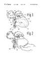
- FIG. 1is a line drawing representing a patient's heart at the time of surgery with a valved right heart bypass device in place.
- the illustrationshows a pivoting leaflet valve which is closed.
- the inferior vena cavais ligated.
- Arrowsindicate blood flow passing from the inferior vena cava, through part of the device, and into the natural right ventricle.
- FIG. 2is a line drawing representing the heart with a right bypass device in place while the heart is manipulated by the surgeon's hand.
- the arrows in the figureindicate the direction of blood flow through the device.
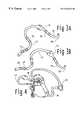
- FIG. 3Ais a line drawing of a similar embodiment of the invention to the one shown in shown in FIG. 2 .
- a flexing polymer leaflet valveis used, and the leaflets are shown open.
- FIG. 3Bis a line drawing of a similar embodiment of the invention to the one shown in shown in FIG. 1 .
- a flexing polymer leaflet valveis used, and the leaflets are shown closed.
- FIG. 4is a diagram of a patient's heart during surgery in which a device of the present invention is used for passive right heart bypass and a centrifugal pump is used for left heart bypass pumping.
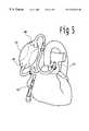
- FIG. 5is a drawing of an embodiment of the invention including a resilient tube which may be squeezed by hand to effect pumping. Dotted lines indicate the tube in a position after it has been squeezed to eject blood.
- the present inventionconstitutes a flexible tube having one end adapted for cannulation of the vena cava and the other end adapted for cannulation of the pulmonary artery.
- a single tubeis sub-optimal because during cannulation air must be vented. Therefore, two tubes and a connector are preferable.
- the devicemay be assembled from components commonly utilized for cardiopulmonary bypass if no internal valve is included.
- FIG. 1shows one highly simplified embodiment.
- the heartincludes the right atrium 2 , the right ventricle 4 , the left atrium 6 , and the left ventricle 8 .
- the shunt 10includes an inflow cannula 12 passed through the right atrium with its tip 13 located in the inferior vena cava.
- the shuntincludes a flexible conduit 14 within which a valve 16 , is contained.
- the conduitis in turn connected to a pulmonary artery cannula 18 with its tip placed in the pulmonary artery 20 .
- the valve 16is adapted to close when the pressure on the pulmonary artery side is higher then the pressure on the right atrial side.
- valve 16opens and blood flows across the shunt as shown by the arrows in FIG. 2 .
- the obstructionis not present, as in FIG. 1, blood flows through the right heart normally.
- FIG. 3Aillustrates the situation with inflow to the right ventricle obstructed so that the blood flow passes through the shunt.
- Two barbed connectors, 23 and 25are provided to attach the two cannula and flexible conduit together, and to permit air venting during surgical placement.
- the inflow cannula 12includes side holes 24 located so that they are positioned within the right atrium during use.
- the valve 16 and theis preferably a simple monocusp or bicusp polymer valve.
- the outflow cannulaincludes a curvature 26 near the point of entry into the pulmonary artery to permit positioning out of the way of surgical access to the heart.
- the inflow cannulaWhen the inflow cannula is placed it is retained and sealed with a umbilical tapes at the right atrium 28 , and also around the inferior vena cava, 30 . Blood flows into the cannula from the IVC through its tip 13 , and from the right atrium via the side holes 24 . When the inflow to the right atrium is not obstructed, as shown in FIG. 3B, the blood from the inferior vena cava flows into the inflow cannula tip and then out through the side holes, permitting it to enter the right ventricle across the tricuspid valve 32 .
- FIG. 4shows the device together with a left ventricular bypass pump 34 placed between the left ventricular apex 36 , and the aorta 38 .
- the shunt and pump togetherpermit the full cardiac output of the patient to be pumped by the assist pump even when the inflow to the right ventricle is obstructed. This permits the heart to be slowed down with drugs such as Esmolol which stills its motion and simplifies coronary artery suturing. It also permits complete arrest of the heart with cold cardioplegia.
- FIG. 5shows a shunt configured to permit temporary pumping by manual massage.
- the deviceincludes an inflow cannula 40 and an outflow cannula 42 , between which is placed a valved pumping chamber 44 .
- This chamberincludes an inflow valve 46 , and an outflow valve 48 .
- the wall of the chamberis constructed of a blood compatible material, preferably an elastomer or other polymer.
- the chambermay be a rather soft walled tube of approximately 50-100 cc volume, or may be a bulb like structure which returns to its full position after being squeezed, like the bulb of a bulb syringe.
- the chamber wallis alternately squeezed and relaxed to actuate it as a pump. Since the period of time while the right ventricular inflow is obstructed by manipulating the heart is usually only about 10-20 minutes, it is practical for the surgeon to manually squeeze the pump at a rate of 30-50 times per minute, which can pump 2-4 L/min of blood at a pressure of about 25-35 mmHg. This can be accomplished without undue fatigue because the pressure in the pulmonary artery is low. Using a manual pump on the left side would also be possible, but since the aortic pressure is higher, its use would be more tiring for the individual squeezing it.
- Cannulationmay be via the inferior vena cava, superior vena cava, right atrial wall, right atrial appendage, right ventricule, main pulmonary artery trunk or via a large branch of the pulmonary artery.
- Cannulation techniquesmay be used including but not limited to fixation of the cannulae in place with ligatures, umbilical tapes, or purse string sutures.
Landscapes
- Health & Medical Sciences (AREA)
- Heart & Thoracic Surgery (AREA)
- Vascular Medicine (AREA)
- Biomedical Technology (AREA)
- Engineering & Computer Science (AREA)
- Anesthesiology (AREA)
- Cardiology (AREA)
- Hematology (AREA)
- Life Sciences & Earth Sciences (AREA)
- Animal Behavior & Ethology (AREA)
- General Health & Medical Sciences (AREA)
- Public Health (AREA)
- Veterinary Medicine (AREA)
- External Artificial Organs (AREA)
Abstract
Description
Surgery for grafting of the coronary arteries has most commonly been done using cardiopulmonary bypass with the heart stopped. Recently, the advantages of avoiding the blood damage caused by the heart lung machine have been recognized, and a number of methods to operate on the coronary arteries without using oxygenators have become more common. The patient's natural heart or some type of heart assist device is used to pump the blood through the body and through the lungs. In some operations, particularly when the heart must be lifted or displaced to gain access to the site of a coronary artery graft anastomosis, the flow through the heart may be diminished due to kinking of the atria or blood vessels directly adjacent to the heart.
In the case of kinking of the inflow to the right side of the heart, blood flow across the lungs will be diminished, which in turn will diminish filling of the left side of the heart which will decrease cardiac output.
The present invention provides a very simple and inexpensive device and method to maintain the cardiac output even while the inflow to the right side of the heart is kinked or obstructed by compression. A passive shunt from the right heart inflow to the pulmonary artery is created which is opened during the time when the natural right inflow is blocked. The preferred embodiment includes an inflow cannula and a pulmonary artery cannula, and a tube connecting them containing a flow actuated valve to prevent back flow from the pulmonary artery. A portion of the tube is adapted to be clamped to shut off the flow completely. The preferred placement is with the inflow cannula in the inferior vena cava and the outflow cannula in the pulmonary artery. The inflow cannula may include side holes adapted to permit blood from the right atrium (originating from the SVC and coronary sinus) to also enter it.
During use, the shunt is placed and either clamped or left so that pressure from the pulmonary artery closes the valve. The patient is then given a sufficient volume of fluid so that his/her right atrial pressure is elevated [above normal] to about 25 mmHg. When the heart is manipulated during surgery and the right inflow is obstructed, the clamp is removed and blood will flow passively through the shunt to bypass the obstruction. This will maintain sufficient blood across the lungs to supply the left heart and maintain the patient's arterial blood pressure.
Alternative embodiments of the shunt include a model with no valve, in which case the surgeon must attend to clamping and un-clamping the shunt as necessary, and another embodiment having two valves and a compressible chamber between them, adapted to be squeezed manually to provide a hand actuated right heart bypass pump.
It is an object of the present invention to provide a device to bypass the right heart during surgical manipulation.
It is a further object of the invention to provide a valved right heart bypass shunt adapted to prevent back flow from the pulmonary artery when the right ventricle is receiving sufficient filling to pump effectively, and automatically act as a shunt when the right heart filling is obstructed.
It is another object of the invention to provide a method to permit surgical manipulation of the heart using a passive right heart bypass shunt.
It is a still further object of the invention to provide a simple, inexpensive right heart bypass pump which is manually actuated by the surgeon during brief periods of use while the natural heart is surgically manipulated.
It is another object of the invention to provide a passive right heart shunt which may be used in conjunction with a left heart assist device so as to maintain the pulmonary circulation even at times when the right heart inflow is obstructed.
FIG. 1 is a line drawing representing a patient's heart at the time of surgery with a valved right heart bypass device in place. The illustration shows a pivoting leaflet valve which is closed. The inferior vena cava is ligated. Arrows indicate blood flow passing from the inferior vena cava, through part of the device, and into the natural right ventricle.
FIG. 2 is a line drawing representing the heart with a right bypass device in place while the heart is manipulated by the surgeon's hand. The arrows in the figure indicate the direction of blood flow through the device.
FIG. 3A is a line drawing of a similar embodiment of the invention to the one shown in shown in FIG.2. In this embodiment, a flexing polymer leaflet valve is used, and the leaflets are shown open.
FIG. 3B is a line drawing of a similar embodiment of the invention to the one shown in shown in FIG.1. In this embodiment, a flexing polymer leaflet valve is used, and the leaflets are shown closed.
FIG. 4 is a diagram of a patient's heart during surgery in which a device of the present invention is used for passive right heart bypass and a centrifugal pump is used for left heart bypass pumping.
FIG. 5 is a drawing of an embodiment of the invention including a resilient tube which may be squeezed by hand to effect pumping. Dotted lines indicate the tube in a position after it has been squeezed to eject blood.
In its most simple form, the present invention constitutes a flexible tube having one end adapted for cannulation of the vena cava and the other end adapted for cannulation of the pulmonary artery. In practice, a single tube is sub-optimal because during cannulation air must be vented. Therefore, two tubes and a connector are preferable. The device may be assembled from components commonly utilized for cardiopulmonary bypass if no internal valve is included. FIG. 1 shows one highly simplified embodiment. The heart includes theright atrium 2, theright ventricle 4, theleft atrium 6, and theleft ventricle 8. Theshunt 10, includes aninflow cannula 12 passed through the right atrium with itstip 13 located in the inferior vena cava. The shunt includes aflexible conduit 14 within which avalve 16, is contained. The conduit is in turn connected to apulmonary artery cannula 18 with its tip placed in thepulmonary artery 20. Thevalve 16 is adapted to close when the pressure on the pulmonary artery side is higher then the pressure on the right atrial side.
During surgery when manipulation of the heart causes obstruction of the flow of blood into the right ventricle (indicated at22 by the X in FIG. 2) thevalve 16 opens and blood flows across the shunt as shown by the arrows in FIG.2. When the obstruction is not present, as in FIG. 1, blood flows through the right heart normally.
The prefered embodiment of the valved shunt is shown in FIG. 3A which illustrates the situation with inflow to the right ventricle obstructed so that the blood flow passes through the shunt. Two barbed connectors,23 and25 are provided to attach the two cannula and flexible conduit together, and to permit air venting during surgical placement. As best seen in FIGS. 1 & 2, theinflow cannula 12 includesside holes 24 located so that they are positioned within the right atrium during use. Thevalve 16 and the is preferably a simple monocusp or bicusp polymer valve. The outflow cannula—includes acurvature 26 near the point of entry into the pulmonary artery to permit positioning out of the way of surgical access to the heart. When the inflow cannula is placed it is retained and sealed with a umbilical tapes at theright atrium 28, and also around the inferior vena cava,30. Blood flows into the cannula from the IVC through itstip 13, and from the right atrium via theside holes 24. When the inflow to the right atrium is not obstructed, as shown in FIG. 3B, the blood from the inferior vena cava flows into the inflow cannula tip and then out through the side holes, permitting it to enter the right ventricle across the tricuspid valve32.
FIG. 4 shows the device together with a leftventricular bypass pump 34 placed between the leftventricular apex 36, and theaorta 38. When used as shown, in conjunction with the left assist pump, the shunt and pump together permit the full cardiac output of the patient to be pumped by the assist pump even when the inflow to the right ventricle is obstructed. This permits the heart to be slowed down with drugs such as Esmolol which stills its motion and simplifies coronary artery suturing. It also permits complete arrest of the heart with cold cardioplegia.
FIG. 5 shows a shunt configured to permit temporary pumping by manual massage. The device includes aninflow cannula 40 and anoutflow cannula 42, between which is placed avalved pumping chamber 44. This chamber includes aninflow valve 46, and anoutflow valve 48. The wall of the chamber is constructed of a blood compatible material, preferably an elastomer or other polymer. The chamber may be a rather soft walled tube of approximately 50-100 cc volume, or may be a bulb like structure which returns to its full position after being squeezed, like the bulb of a bulb syringe. In use, during periods of time when the surgeon needs to increase the flow into the pulmonary artery, the chamber wall is alternately squeezed and relaxed to actuate it as a pump. Since the period of time while the right ventricular inflow is obstructed by manipulating the heart is usually only about 10-20 minutes, it is practical for the surgeon to manually squeeze the pump at a rate of 30-50 times per minute, which can pump 2-4 L/min of blood at a pressure of about 25-35 mmHg. This can be accomplished without undue fatigue because the pressure in the pulmonary artery is low. Using a manual pump on the left side would also be possible, but since the aortic pressure is higher, its use would be more tiring for the individual squeezing it.
The information disclosed in the description of the present invention is intended to be representative of the principles I have described. For example, Various commonly applied methods of canulation and combinations of access sites may be used without departing from the scope of the present invention. Cannulation may be via the inferior vena cava, superior vena cava, right atrial wall, right atrial appendage, right ventricule, main pulmonary artery trunk or via a large branch of the pulmonary artery. A number of commonly applied cannulation techniques may be used including but not limited to fixation of the cannulae in place with ligatures, umbilical tapes, or purse string sutures. It will thus be seen that the objects of the invention set forth above and those made apparent from the preceding description are efficiently obtained and that certain changes may be made in the above articles and constructions without departing from the scope of the invention. It is intended that all matter contained in the above description and shown in the accompanying drawings shall be interpreted as illustrative but not in a limiting sense. It is also understood that the following claims are intended to cover all of the generic and specific features of the invention herein described and all statements of the scope of the invention which, as a matter of language, might be said to fall there between.
Claims (11)
1. A passive right atrium to pulmonary artery shunt, for use during coronary artery bypass surgery comprising;
a. A venous uptake cannula to remove blood from the inferior vena cave, superior vena cava, or right atrium, or from any combination of those vascular structures,
b. A second cannula to introduce blood into the pulmonary artery, and,
c. Means to connect said venous uptake cannula to said pulmonary artery cannula.
2. The passive shunt ofclaim 1 further including a tube interconnecting said inflow cannula and said pulmonary artery cannula having a portion of said tube adapted to be clamped by the surgeon.
3. The passive shunt ofclaim 1 further including valve means to permit flow from said shunt into the pulmonary artery when said valve means are open and to prevent flow from the pulmonary artery into the shunt when said valve means are closed.
4. The passive shunt ofclaim 3 in which said valve means comprise a polymer valve.
5. The passive shunt ofclaim 3 in which said valve means comprise a pivoting leaflet or flow accuated valve.
6. The passive shunt ofclaim 1 in which said venous uptake cannula has one or more side holes positioned such that when said cannula is inserted across the right atrium and into the inferior vena cava, said side holes will reside within the right atrium.
7. A manually actuated right heart bypass pump comprising,
a. A venous uptake cannula to remove blood from the inferior vena cave, superior vena cava, or right atrium, or from any combination of those vascular structures,
b. A second cannula to introduce blood into the pulmonary artery,
c. A manually compressible polymeric pumping chamber interposed between said venous uptake cannula to said pulmonary artery cannula including both inflow valve means and outflow valve means which permit blood to enter said chamber only from said venous uptake cannula means, and to exit said chamber only through said pulmonary artery cannula means.
8. The manually actuated right heart bypass pump ofclaim 7 in which said compressible pumping chamber is a soft walled tube.
9. The manually actuated right heart bypass pump ofclaim 7 in which said compressible pumping chamber includes resilient means to change its shape so as to increase the volume within it when it is manually released after having been manually compressed.
10. A method of sustaining adequate circulatory function during manipulation or retraction of the heart comprising,
a. Creating an alternate path (shunt) for blood to flow around a portion of the anatomic structure conducting blood into the right ventricle which is susceptible to obstruction by kinking or compression during manipulation or surgical retraction of the heart,
b. Increasing the right atrial blood pressure above normal, and,
c. Occluding said shunt with clamping means or valve means during times when the inflow to the right ventricle is not obstructed.
11. The method of sustaining adequate circulatory function during manipulation or retraction of the heart ofclaim 10 , in which said shunt includes manually actuated pumping means and said pumping means are employed during the period of time that the heart is manipulated or retracted.
Priority Applications (1)
| Application Number | Priority Date | Filing Date | Title |
|---|---|---|---|
| US09/356,446US6344022B1 (en) | 1999-07-19 | 1999-07-19 | Right ventricular bypass devices and methods of their use during heart surgery |
Applications Claiming Priority (1)
| Application Number | Priority Date | Filing Date | Title |
|---|---|---|---|
| US09/356,446US6344022B1 (en) | 1999-07-19 | 1999-07-19 | Right ventricular bypass devices and methods of their use during heart surgery |
Publications (1)
| Publication Number | Publication Date |
|---|---|
| US6344022B1true US6344022B1 (en) | 2002-02-05 |
Family
ID=23401453
Family Applications (1)
| Application Number | Title | Priority Date | Filing Date |
|---|---|---|---|
| US09/356,446Expired - Fee RelatedUS6344022B1 (en) | 1999-07-19 | 1999-07-19 | Right ventricular bypass devices and methods of their use during heart surgery |
Country Status (1)
| Country | Link |
|---|---|
| US (1) | US6344022B1 (en) |
Cited By (46)
| Publication number | Priority date | Publication date | Assignee | Title |
|---|---|---|---|---|
| US20020173742A1 (en)* | 2001-04-20 | 2002-11-21 | Gad Keren | Methods and apparatus for reducing localized circulatory system pressure |
| US20030199727A1 (en)* | 2002-04-19 | 2003-10-23 | Burke David J. | Adaptive speed control for blood pump |
| US20040242954A1 (en)* | 2003-05-30 | 2004-12-02 | Moises Calderon | Universal pneumatic ventricular assist device |
| GB2404860A (en)* | 2003-08-11 | 2005-02-16 | Mohie Eldin Omar | Arterial haemodialysis graft |
| US20050148925A1 (en)* | 2001-04-20 | 2005-07-07 | Dan Rottenberg | Device and method for controlling in-vivo pressure |
| US20070156006A1 (en)* | 2005-06-06 | 2007-07-05 | The Cleveland Clinic Foundation And Foster-Miller, Inc. | Blood pump |
| US20090112049A1 (en)* | 2007-10-29 | 2009-04-30 | Saudi Arabian Oil Company | Heart pump apparatus and method for beating heart surgery |
| US20100004501A1 (en)* | 2008-05-05 | 2010-01-07 | Coherex Medical, Inc. | Ventricular assist device and related methods |
| US20110130619A1 (en)* | 2008-05-05 | 2011-06-02 | Coherex Medical, Inc. | Ventricular assist device and related methods |
| US8696611B2 (en) | 2009-05-04 | 2014-04-15 | V-Wave Ltd. | Device and method for regulating pressure in a heart chamber |
| US8771164B2 (en) | 2008-03-28 | 2014-07-08 | Vitalmex Internacional S.A. De C.V. | Fluid pumping ventricular assist device and components with static seal |
| US9034034B2 (en) | 2010-12-22 | 2015-05-19 | V-Wave Ltd. | Devices for reducing left atrial pressure, and methods of making and using same |
| CN105561412A (en)* | 2016-02-02 | 2016-05-11 | 丁以群 | Heart assisting device |
| US9629715B2 (en) | 2011-07-28 | 2017-04-25 | V-Wave Ltd. | Devices for reducing left atrial pressure having biodegradable constriction, and methods of making and using same |
| US9681948B2 (en) | 2006-01-23 | 2017-06-20 | V-Wave Ltd. | Heart anchor device |
| US9713696B2 (en) | 2013-05-21 | 2017-07-25 | V-Wave Ltd. | Apparatus and methods for delivering devices for reducing left atrial pressure |
| US9775936B2 (en) | 2010-10-18 | 2017-10-03 | WorldHeart Corp. | Blood pump with separate mixed-flow and axial-flow impeller stages, components therefor and related methods |
| US10076403B1 (en) | 2009-05-04 | 2018-09-18 | V-Wave Ltd. | Shunt for redistributing atrial blood volume |
| US10111994B2 (en) | 2013-05-14 | 2018-10-30 | Heartware, Inc. | Blood pump with separate mixed-flow and axial-flow impeller stages and multi-stage stators |
| US20200085600A1 (en)* | 2018-09-19 | 2020-03-19 | NXT Biomedical | Methods And Technology For Creating Connections And Shunts Between Vessels And Chambers Of Biologic Structures |
| US10835394B2 (en) | 2016-05-31 | 2020-11-17 | V-Wave, Ltd. | Systems and methods for making encapsulated hourglass shaped stents |
| US10898698B1 (en) | 2020-05-04 | 2021-01-26 | V-Wave Ltd. | Devices with dimensions that can be reduced and increased in vivo, and methods of making and using the same |
| US10925706B2 (en) | 2009-05-04 | 2021-02-23 | V-Wave Ltd. | Shunt for redistributing atrial blood volume |
| US10940296B2 (en) | 2015-05-07 | 2021-03-09 | The Medical Research, Infrastructure and Health Services Fund of the Tel Aviv Medical Center | Temporary interatrial shunts |
| US11109988B2 (en) | 2016-05-31 | 2021-09-07 | V-Wave Ltd. | Systems and methods for making encapsulated hourglass shaped stents |
| US11135054B2 (en) | 2011-07-28 | 2021-10-05 | V-Wave Ltd. | Interatrial shunts having biodegradable material, and methods of making and using same |
| US11234702B1 (en) | 2020-11-13 | 2022-02-01 | V-Wave Ltd. | Interatrial shunt having physiologic sensor |
| US11241572B2 (en) | 2018-09-25 | 2022-02-08 | Tc1 Llc | Adaptive speed control algorithms and controllers for optimizing flow in ventricular assist devices |
| US11291807B2 (en) | 2017-03-03 | 2022-04-05 | V-Wave Ltd. | Asymmetric shunt for redistributing atrial blood volume |
| US11458287B2 (en) | 2018-01-20 | 2022-10-04 | V-Wave Ltd. | Devices with dimensions that can be reduced and increased in vivo, and methods of making and using the same |
| US11612385B2 (en) | 2019-04-03 | 2023-03-28 | V-Wave Ltd. | Systems and methods for delivering implantable devices across an atrial septum |
| US11744589B2 (en) | 2018-01-20 | 2023-09-05 | V-Wave Ltd. | Devices and methods for providing passage between heart chambers |
| US11752314B2 (en) | 2019-02-07 | 2023-09-12 | Nxt Biomedical, Llc | Rivet shunt and method of deployment |
| US11801369B2 (en) | 2020-08-25 | 2023-10-31 | Shifamed Holdings, Llc | Adjustable interatrial shunts and associated systems and methods |
| US11813386B2 (en) | 2022-04-14 | 2023-11-14 | V-Wave Ltd. | Interatrial shunt with expanded neck region |
| US11850138B2 (en) | 2009-05-04 | 2023-12-26 | V-Wave Ltd. | Shunt for redistributing atrial blood volume |
| US11857197B2 (en) | 2020-11-12 | 2024-01-02 | Shifamed Holdings, Llc | Adjustable implantable devices and associated methods |
| US11865282B2 (en) | 2019-05-20 | 2024-01-09 | V-Wave Ltd. | Systems and methods for creating an interatrial shunt |
| US12090290B2 (en) | 2021-03-09 | 2024-09-17 | Shifamed Holdings, Llc | Shape memory actuators for adjustable shunting systems, and associated systems and methods |
| US12151071B2 (en) | 2019-09-09 | 2024-11-26 | Shifamed Holdings, Llc | Adjustable shunts and associated systems and methods |
| US12186176B2 (en) | 2009-05-04 | 2025-01-07 | V-Wave Ltd. | Shunt for redistributing atrial blood volume |
| US12213817B2 (en) | 2020-04-23 | 2025-02-04 | Shifamed Holdings, Llc | Systems and methods for radiographic monitoring of shunts |
| US12226602B2 (en) | 2019-04-03 | 2025-02-18 | V-Wave Ltd. | Systems for delivering implantable devices across an atrial septum |
| US12296122B2 (en) | 2023-10-18 | 2025-05-13 | V-Wave Ltd. | Hybrid devices with dimensions that can be adjusted in vivo and methods of manufacturing thereof |
| US12357792B2 (en) | 2019-01-04 | 2025-07-15 | Shifamed Holdings, Llc | Internal recharging systems and methods of use |
| US12440656B2 (en) | 2021-04-23 | 2025-10-14 | Shifamed Holdings, Llc | Power management for interatrial shunts and associated systems and methods |
Citations (5)
| Publication number | Priority date | Publication date | Assignee | Title |
|---|---|---|---|---|
| US4008710A (en) | 1973-08-11 | 1977-02-22 | Horst Chmiel | Blood pump |
| US5743845A (en) | 1995-01-12 | 1998-04-28 | Runge; Thomas M. | Biventricular pulsatile cardiac support system having a mechanically balanced stroke volume |
| US5984956A (en) | 1997-10-06 | 1999-11-16 | Heartstent Corporation | Transmyocardial implant |
| US6090140A (en) | 1999-02-17 | 2000-07-18 | Shelhigh, Inc. | Extra-anatomic heart valve apparatus |
| US6139487A (en) | 1997-04-02 | 2000-10-31 | Impella Cardiotechnik Ag | Intracardiac pump device |
- 1999
- 1999-07-19USUS09/356,446patent/US6344022B1/ennot_activeExpired - Fee Related
Patent Citations (5)
| Publication number | Priority date | Publication date | Assignee | Title |
|---|---|---|---|---|
| US4008710A (en) | 1973-08-11 | 1977-02-22 | Horst Chmiel | Blood pump |
| US5743845A (en) | 1995-01-12 | 1998-04-28 | Runge; Thomas M. | Biventricular pulsatile cardiac support system having a mechanically balanced stroke volume |
| US6139487A (en) | 1997-04-02 | 2000-10-31 | Impella Cardiotechnik Ag | Intracardiac pump device |
| US5984956A (en) | 1997-10-06 | 1999-11-16 | Heartstent Corporation | Transmyocardial implant |
| US6090140A (en) | 1999-02-17 | 2000-07-18 | Shelhigh, Inc. | Extra-anatomic heart valve apparatus |
Cited By (107)
| Publication number | Priority date | Publication date | Assignee | Title |
|---|---|---|---|---|
| US8235933B2 (en) | 2001-04-20 | 2012-08-07 | V-Wave Ltd. | Methods and apparatus for reducing localized circulatory system pressure |
| US20110218477A1 (en)* | 2001-04-20 | 2011-09-08 | V- Wave Ltd., | Methods and apparatus for reducing localized circulatory system pressure |
| US8091556B2 (en)* | 2001-04-20 | 2012-01-10 | V-Wave Ltd. | Methods and apparatus for reducing localized circulatory system pressure |
| US20050148925A1 (en)* | 2001-04-20 | 2005-07-07 | Dan Rottenberg | Device and method for controlling in-vivo pressure |
| US20110218481A1 (en)* | 2001-04-20 | 2011-09-08 | Dan Rottenberg | Device and method for controlling in-vivo pressure |
| US9943670B2 (en) | 2001-04-20 | 2018-04-17 | V-Wave Ltd. | Methods and apparatus for reducing localized circulatory system pressure |
| US9724499B2 (en) | 2001-04-20 | 2017-08-08 | V-Wave Ltd. | Device and method for controlling in-vivo pressure |
| US10207087B2 (en) | 2001-04-20 | 2019-02-19 | HemoDynamx Technologies, Ltd. | Methods and apparatus for reducing localized circulatory system pressure |
| US20020173742A1 (en)* | 2001-04-20 | 2002-11-21 | Gad Keren | Methods and apparatus for reducing localized circulatory system pressure |
| US8328751B2 (en) | 2001-04-20 | 2012-12-11 | V-Wave Ltd. | Methods and apparatus for reducing localized circulatory system pressure |
| US20030199727A1 (en)* | 2002-04-19 | 2003-10-23 | Burke David J. | Adaptive speed control for blood pump |
| US6991595B2 (en) | 2002-04-19 | 2006-01-31 | Thoratec Corporation | Adaptive speed control for blood pump |
| US7217236B2 (en) | 2003-05-30 | 2007-05-15 | Innovamedica S.A. De C.V. | Universal pneumatic ventricular assist device |
| US20040242954A1 (en)* | 2003-05-30 | 2004-12-02 | Moises Calderon | Universal pneumatic ventricular assist device |
| GB2404860A (en)* | 2003-08-11 | 2005-02-16 | Mohie Eldin Omar | Arterial haemodialysis graft |
| US20070282157A1 (en)* | 2004-02-03 | 2007-12-06 | Atria Medical Inc. | Device And Method For Controlling In-Vivo Pressure |
| US11382747B2 (en) | 2004-02-03 | 2022-07-12 | V-Wave, Ltd. | Device and method for controlling in-vivo pressure |
| US12303390B2 (en) | 2004-02-03 | 2025-05-20 | V-Wave Ltd. | Device and method for controlling in-vivo pressure |
| US8070708B2 (en) | 2004-02-03 | 2011-12-06 | V-Wave Limited | Device and method for controlling in-vivo pressure |
| US10463490B2 (en) | 2004-02-03 | 2019-11-05 | V-Wave Ltd. | Device and method for controlling in-vivo pressure |
| US11266501B2 (en) | 2004-02-03 | 2022-03-08 | V-Wave Ltd. | Device and method for controlling in-vivo pressure |
| US10912645B2 (en) | 2004-02-03 | 2021-02-09 | V-Wave Ltd. | Device and method for controlling in-vivo pressure |
| US8992407B2 (en) | 2005-06-06 | 2015-03-31 | The Cleveland Clinic Foundation | Blood pump |
| US11185678B2 (en) | 2005-06-06 | 2021-11-30 | The Cleveland Clinic Foundation | Blood pump |
| US10369260B2 (en) | 2005-06-06 | 2019-08-06 | The Cleveland Clinic Foundation | Blood pump |
| US8177703B2 (en) | 2005-06-06 | 2012-05-15 | The Cleveland Clinic Foundation | Blood pump |
| US9950101B2 (en) | 2005-06-06 | 2018-04-24 | The Cleveland Clinic Foundation | Blood pump |
| US20070156006A1 (en)* | 2005-06-06 | 2007-07-05 | The Cleveland Clinic Foundation And Foster-Miller, Inc. | Blood pump |
| US10357357B2 (en) | 2006-01-23 | 2019-07-23 | V-Wave Ltd. | Heart anchor device |
| US11253353B2 (en) | 2006-01-23 | 2022-02-22 | V-Wave Ltd. | Heart anchor device |
| US9681948B2 (en) | 2006-01-23 | 2017-06-20 | V-Wave Ltd. | Heart anchor device |
| WO2009058775A3 (en)* | 2007-10-29 | 2009-06-25 | Saudi Arabian Oil Co | Heart pump apparatus and method for beating heart surgery |
| US20090112049A1 (en)* | 2007-10-29 | 2009-04-30 | Saudi Arabian Oil Company | Heart pump apparatus and method for beating heart surgery |
| US8771164B2 (en) | 2008-03-28 | 2014-07-08 | Vitalmex Internacional S.A. De C.V. | Fluid pumping ventricular assist device and components with static seal |
| US8869395B2 (en) | 2008-03-28 | 2014-10-28 | Vitalmex Internacional S.A. De C.V. | Fluid pumping device and components with static seal |
| US9421310B2 (en) | 2008-05-05 | 2016-08-23 | Coherex Medical, Inc. | Ventricular assist device and related methods |
| US8845509B2 (en) | 2008-05-05 | 2014-09-30 | Coherex Medical, Inc. | Ventricular assist device and related methods |
| US20100004501A1 (en)* | 2008-05-05 | 2010-01-07 | Coherex Medical, Inc. | Ventricular assist device and related methods |
| WO2009137530A3 (en)* | 2008-05-05 | 2010-04-22 | Coherex Medical, Inc. | Ventricular assist device and related methods |
| US20110130619A1 (en)* | 2008-05-05 | 2011-06-02 | Coherex Medical, Inc. | Ventricular assist device and related methods |
| US8235885B2 (en) | 2008-05-05 | 2012-08-07 | Coherex Medical, Inc. | Ventricular assist device and related methods |
| US10493191B2 (en) | 2008-05-05 | 2019-12-03 | Coherex Medical, Inc. | Ventricular assist device and related methods |
| US8540616B2 (en) | 2008-05-05 | 2013-09-24 | Coherex Medical, Inc. | Ventricular assist device and related methods |
| US8579791B2 (en) | 2008-05-05 | 2013-11-12 | Coherex Medical, Inc. | Ventricular assist device and related methods |
| US10124100B2 (en) | 2008-05-05 | 2018-11-13 | Coherex Medical, Inc. | Ventricular assist device and related methods |
| US10076403B1 (en) | 2009-05-04 | 2018-09-18 | V-Wave Ltd. | Shunt for redistributing atrial blood volume |
| US9707382B2 (en) | 2009-05-04 | 2017-07-18 | V-Wave Ltd. | Device and method for regulating pressure in a heart chamber |
| US10925706B2 (en) | 2009-05-04 | 2021-02-23 | V-Wave Ltd. | Shunt for redistributing atrial blood volume |
| US12005214B2 (en) | 2009-05-04 | 2024-06-11 | V-Wave Ltd. | Device and method for regulating pressure in a heart chamber |
| US10251740B2 (en) | 2009-05-04 | 2019-04-09 | V-Wave Ltd. | Shunt for redistributing atrial blood volume |
| US10828151B2 (en) | 2009-05-04 | 2020-11-10 | V-Wave Ltd. | Devices for reducing left atrial pressure, and methods of making and using same |
| US8696611B2 (en) | 2009-05-04 | 2014-04-15 | V-Wave Ltd. | Device and method for regulating pressure in a heart chamber |
| US11850138B2 (en) | 2009-05-04 | 2023-12-26 | V-Wave Ltd. | Shunt for redistributing atrial blood volume |
| US12186176B2 (en) | 2009-05-04 | 2025-01-07 | V-Wave Ltd. | Shunt for redistributing atrial blood volume |
| US9980815B2 (en) | 2009-05-04 | 2018-05-29 | V-Wave Ltd. | Devices for reducing left atrial pressure, and methods of making and using same |
| US10639459B2 (en) | 2009-05-04 | 2020-05-05 | V-Wave Ltd. | Device and method for regulating pressure in a heart chamber |
| US10371150B2 (en) | 2010-10-18 | 2019-08-06 | WorldHeart Corp. | Blood pump with separate mixed-flow and axial-flow impeller stages, components therefor and related methods |
| US9775936B2 (en) | 2010-10-18 | 2017-10-03 | WorldHeart Corp. | Blood pump with separate mixed-flow and axial-flow impeller stages, components therefor and related methods |
| US9034034B2 (en) | 2010-12-22 | 2015-05-19 | V-Wave Ltd. | Devices for reducing left atrial pressure, and methods of making and using same |
| US9629715B2 (en) | 2011-07-28 | 2017-04-25 | V-Wave Ltd. | Devices for reducing left atrial pressure having biodegradable constriction, and methods of making and using same |
| US11135054B2 (en) | 2011-07-28 | 2021-10-05 | V-Wave Ltd. | Interatrial shunts having biodegradable material, and methods of making and using same |
| US10368981B2 (en) | 2011-07-28 | 2019-08-06 | V-Wave Ltd. | Devices for reducing left atrial pressure having biodegradable constriction, and methods of making and using same |
| US10434232B2 (en) | 2013-05-14 | 2019-10-08 | Heartware, Inc. | Blood pump with separate mixed-flow and axial-flow impeller stages and multi-stage stators |
| US10111994B2 (en) | 2013-05-14 | 2018-10-30 | Heartware, Inc. | Blood pump with separate mixed-flow and axial-flow impeller stages and multi-stage stators |
| US10478594B2 (en) | 2013-05-21 | 2019-11-19 | V-Wave Ltd. | Apparatus and methods for delivering devices for reducing left atrial pressure |
| US9713696B2 (en) | 2013-05-21 | 2017-07-25 | V-Wave Ltd. | Apparatus and methods for delivering devices for reducing left atrial pressure |
| US11690976B2 (en) | 2013-05-21 | 2023-07-04 | V-Wave Ltd. | Apparatus and methods for delivering devices for reducing left atrial pressure |
| US10940296B2 (en) | 2015-05-07 | 2021-03-09 | The Medical Research, Infrastructure and Health Services Fund of the Tel Aviv Medical Center | Temporary interatrial shunts |
| US12186510B2 (en) | 2015-05-07 | 2025-01-07 | The Medical Research, Infrastructure And Health Services Fund Of The Tel-Aviv Medical Center | Temporary interatrial shunts |
| CN105561412B (en)* | 2016-02-02 | 2018-02-23 | 丁以群 | Heart-assist device |
| CN105561412A (en)* | 2016-02-02 | 2016-05-11 | 丁以群 | Heart assisting device |
| US11304831B2 (en) | 2016-05-31 | 2022-04-19 | V-Wave Ltd. | Systems and methods for making encapsulated hourglass shaped stents |
| US11497631B2 (en) | 2016-05-31 | 2022-11-15 | V-Wave Ltd. | Systems and methods for making encapsulated hourglass shaped stents |
| US11607327B2 (en) | 2016-05-31 | 2023-03-21 | V-Wave Ltd. | Systems and methods for making encapsulated hourglass shaped stents |
| US10835394B2 (en) | 2016-05-31 | 2020-11-17 | V-Wave, Ltd. | Systems and methods for making encapsulated hourglass shaped stents |
| US11109988B2 (en) | 2016-05-31 | 2021-09-07 | V-Wave Ltd. | Systems and methods for making encapsulated hourglass shaped stents |
| US12311134B2 (en) | 2017-03-03 | 2025-05-27 | V-Wave Ltd. | Asymmetric shunt for redistributing atrial blood volume |
| US11291807B2 (en) | 2017-03-03 | 2022-04-05 | V-Wave Ltd. | Asymmetric shunt for redistributing atrial blood volume |
| US11458287B2 (en) | 2018-01-20 | 2022-10-04 | V-Wave Ltd. | Devices with dimensions that can be reduced and increased in vivo, and methods of making and using the same |
| US12349912B2 (en) | 2018-01-20 | 2025-07-08 | V-Wave Ltd. | Devices and methods for providing passage between heart chambers |
| US11744589B2 (en) | 2018-01-20 | 2023-09-05 | V-Wave Ltd. | Devices and methods for providing passage between heart chambers |
| US20200085600A1 (en)* | 2018-09-19 | 2020-03-19 | NXT Biomedical | Methods And Technology For Creating Connections And Shunts Between Vessels And Chambers Of Biologic Structures |
| US20230320877A1 (en)* | 2018-09-19 | 2023-10-12 | Nxt Biomedical, Llc | Methods And Technology For Creating Connections And Shunts Between Vessels And Chambers Of Biologic Structures |
| US11717429B2 (en)* | 2018-09-19 | 2023-08-08 | Nxt Biomedical, Llc | Methods and technology for creating connections and shunts between vessels and chambers of biologic structures |
| US12376978B2 (en)* | 2018-09-19 | 2025-08-05 | Nxt Biomedical, Llc | Methods and technology for creating connections and shunts between vessels and chambers of biologic structures |
| US11241572B2 (en) | 2018-09-25 | 2022-02-08 | Tc1 Llc | Adaptive speed control algorithms and controllers for optimizing flow in ventricular assist devices |
| US11998730B2 (en) | 2018-09-25 | 2024-06-04 | Tc1 Llc | Adaptive speed control algorithms and controllers for optimizing flow in ventricular assist devices |
| US12357792B2 (en) | 2019-01-04 | 2025-07-15 | Shifamed Holdings, Llc | Internal recharging systems and methods of use |
| US11752314B2 (en) | 2019-02-07 | 2023-09-12 | Nxt Biomedical, Llc | Rivet shunt and method of deployment |
| US12083299B2 (en) | 2019-02-07 | 2024-09-10 | Nxt Biomedical, Llc | Rivet shunt and method of deployment |
| US12226602B2 (en) | 2019-04-03 | 2025-02-18 | V-Wave Ltd. | Systems for delivering implantable devices across an atrial septum |
| US11612385B2 (en) | 2019-04-03 | 2023-03-28 | V-Wave Ltd. | Systems and methods for delivering implantable devices across an atrial septum |
| US11865282B2 (en) | 2019-05-20 | 2024-01-09 | V-Wave Ltd. | Systems and methods for creating an interatrial shunt |
| US12343487B2 (en) | 2019-09-09 | 2025-07-01 | Shifamed Holdings, Llc | Adjustable shunts and associated systems and methods |
| US12151071B2 (en) | 2019-09-09 | 2024-11-26 | Shifamed Holdings, Llc | Adjustable shunts and associated systems and methods |
| US12213817B2 (en) | 2020-04-23 | 2025-02-04 | Shifamed Holdings, Llc | Systems and methods for radiographic monitoring of shunts |
| US10898698B1 (en) | 2020-05-04 | 2021-01-26 | V-Wave Ltd. | Devices with dimensions that can be reduced and increased in vivo, and methods of making and using the same |
| US12251529B2 (en) | 2020-05-04 | 2025-03-18 | V-Wave Ltd. | Devices with dimensions that can be reduced and increased in vivo, and methods of making and using the same |
| US12115328B2 (en) | 2020-05-04 | 2024-10-15 | V-Wave Ltd. | Devices with dimensions that can be reduced and increased in vivo, and methods of making and using the same |
| US11801369B2 (en) | 2020-08-25 | 2023-10-31 | Shifamed Holdings, Llc | Adjustable interatrial shunts and associated systems and methods |
| US11857197B2 (en) | 2020-11-12 | 2024-01-02 | Shifamed Holdings, Llc | Adjustable implantable devices and associated methods |
| US11234702B1 (en) | 2020-11-13 | 2022-02-01 | V-Wave Ltd. | Interatrial shunt having physiologic sensor |
| US12369918B2 (en) | 2020-11-13 | 2025-07-29 | V-Wave Ltd. | Interatrial shunt having physiologic sensor |
| US12090290B2 (en) | 2021-03-09 | 2024-09-17 | Shifamed Holdings, Llc | Shape memory actuators for adjustable shunting systems, and associated systems and methods |
| US12440656B2 (en) | 2021-04-23 | 2025-10-14 | Shifamed Holdings, Llc | Power management for interatrial shunts and associated systems and methods |
| US11813386B2 (en) | 2022-04-14 | 2023-11-14 | V-Wave Ltd. | Interatrial shunt with expanded neck region |
| US12296122B2 (en) | 2023-10-18 | 2025-05-13 | V-Wave Ltd. | Hybrid devices with dimensions that can be adjusted in vivo and methods of manufacturing thereof |
Similar Documents
| Publication | Publication Date | Title |
|---|---|---|
| US6344022B1 (en) | Right ventricular bypass devices and methods of their use during heart surgery | |
| US6979423B2 (en) | Cardiopulmonary bypass device and method | |
| US5957879A (en) | Methods and devices for maintaining cardiopulmonary bypass and arresting a patient's heart | |
| US6280432B1 (en) | Clip-on access port and methods of use | |
| US5330451A (en) | Multi purpose perfusion cannula | |
| EP2195043B1 (en) | Intraatrial ventricular assist device | |
| JP2023036928A (en) | self sealing cannula | |
| Arabia et al. | Implantation technique for the CardioWest total artificial heart | |
| WO2009058775A2 (en) | Heart pump apparatus and method for beating heart surgery | |
| EP4021528A1 (en) | Cannula for endovascular blood circuit support, corresponding assembly, method and cannula system | |
| US20050010077A1 (en) | Low flow atrial-arterial shunt for pump-assisted myocardial revascularization without cardiopulmonary bypass | |
| JP2021529054A (en) | Vascular access tube | |
| US6620121B1 (en) | Pulse wave generator for cardiopulmonary bypass and extracorporeal oxygenation apparatus | |
| US10675395B2 (en) | Pulmonary-systemic shunt devices and related methods | |
| Kshettry et al. | Risk of left ventricular assist device as a bridge to heart transplant following postinfarction ventricular septal rupture | |
| Sobieski et al. | Peripheral cardiopulmonary bypass with modified assisted venous drainage and transthoracic aortic crossclamp: optimal management for robotic mitral valve repair | |
| Lenoir et al. | Simplified temporary right ventricular support after implantation of a left ventricular assist device | |
| RU2734136C1 (en) | System and method for selective bilateral perfusion of cerebrum in reconstructive operation on aortic arch performed in conditions of artificial circulation | |
| US20250312136A1 (en) | Graft-Integrated Intravascular Catheter Fixation | |
| US20240424282A1 (en) | Minimally Invasive Single Port Pulsatile Ventricular Assist Device | |
| Gregoric et al. | HeartMate vented-electric left ventricular assist system: technique for intrathoracic or intraperitoneal implantation via a left thoracotomy | |
| JPH02286170A (en) | Exocirculating device | |
| Liotta | Novel Left Ventricular Assist System® II | |
| Johansson et al. | Left heart bypass by means of A transplanted hear!: A preliminary report | |
| Litwak et al. | Concepts and clinical experience with a left ventricular assist device after intracardiac operation |
Legal Events
| Date | Code | Title | Description |
|---|---|---|---|
| FEPP | Fee payment procedure | Free format text:PAYOR NUMBER ASSIGNED (ORIGINAL EVENT CODE: ASPN); ENTITY STATUS OF PATENT OWNER: SMALL ENTITY | |
| FPAY | Fee payment | Year of fee payment:4 | |
| FPAY | Fee payment | Year of fee payment:8 | |
| REMI | Maintenance fee reminder mailed | ||
| LAPS | Lapse for failure to pay maintenance fees | ||
| STCH | Information on status: patent discontinuation | Free format text:PATENT EXPIRED DUE TO NONPAYMENT OF MAINTENANCE FEES UNDER 37 CFR 1.362 | |
| FP | Lapsed due to failure to pay maintenance fee | Effective date:20140205 |