US6343991B1 - Game control with analog pressure sensor - Google Patents
Game control with analog pressure sensorDownload PDFInfo
- Publication number
- US6343991B1 US6343991B1US09/510,572US51057200AUS6343991B1US 6343991 B1US6343991 B1US 6343991B1US 51057200 AUS51057200 AUS 51057200AUS 6343991 B1US6343991 B1US 6343991B1
- Authority
- US
- United States
- Prior art keywords
- pressure
- game control
- game
- hand
- control according
- Prior art date
- Legal status (The legal status is an assumption and is not a legal conclusion. Google has not performed a legal analysis and makes no representation as to the accuracy of the status listed.)
- Expired - Lifetime
Links
Images


Classifications
- A—HUMAN NECESSITIES
- A63—SPORTS; GAMES; AMUSEMENTS
- A63F—CARD, BOARD, OR ROULETTE GAMES; INDOOR GAMES USING SMALL MOVING PLAYING BODIES; VIDEO GAMES; GAMES NOT OTHERWISE PROVIDED FOR
- A63F13/00—Video games, i.e. games using an electronically generated display having two or more dimensions
- A63F13/20—Input arrangements for video game devices
- A63F13/21—Input arrangements for video game devices characterised by their sensors, purposes or types
- A63F13/218—Input arrangements for video game devices characterised by their sensors, purposes or types using pressure sensors, e.g. generating a signal proportional to the pressure applied by the player
- G—PHYSICS
- G06—COMPUTING OR CALCULATING; COUNTING
- G06F—ELECTRIC DIGITAL DATA PROCESSING
- G06F3/00—Input arrangements for transferring data to be processed into a form capable of being handled by the computer; Output arrangements for transferring data from processing unit to output unit, e.g. interface arrangements
- G06F3/01—Input arrangements or combined input and output arrangements for interaction between user and computer
- G06F3/03—Arrangements for converting the position or the displacement of a member into a coded form
- G06F3/033—Pointing devices displaced or positioned by the user, e.g. mice, trackballs, pens or joysticks; Accessories therefor
- G06F3/0338—Pointing devices displaced or positioned by the user, e.g. mice, trackballs, pens or joysticks; Accessories therefor with detection of limited linear or angular displacement of an operating part of the device from a neutral position, e.g. isotonic or isometric joysticks
- G—PHYSICS
- G06—COMPUTING OR CALCULATING; COUNTING
- G06F—ELECTRIC DIGITAL DATA PROCESSING
- G06F3/00—Input arrangements for transferring data to be processed into a form capable of being handled by the computer; Output arrangements for transferring data from processing unit to output unit, e.g. interface arrangements
- G06F3/01—Input arrangements or combined input and output arrangements for interaction between user and computer
- G06F3/048—Interaction techniques based on graphical user interfaces [GUI]
- G06F3/0484—Interaction techniques based on graphical user interfaces [GUI] for the control of specific functions or operations, e.g. selecting or manipulating an object, an image or a displayed text element, setting a parameter value or selecting a range
- G06F3/04847—Interaction techniques to control parameter settings, e.g. interaction with sliders or dials
- G—PHYSICS
- G06—COMPUTING OR CALCULATING; COUNTING
- G06F—ELECTRIC DIGITAL DATA PROCESSING
- G06F3/00—Input arrangements for transferring data to be processed into a form capable of being handled by the computer; Output arrangements for transferring data from processing unit to output unit, e.g. interface arrangements
- G06F3/01—Input arrangements or combined input and output arrangements for interaction between user and computer
- G06F3/048—Interaction techniques based on graphical user interfaces [GUI]
- G06F3/0484—Interaction techniques based on graphical user interfaces [GUI] for the control of specific functions or operations, e.g. selecting or manipulating an object, an image or a displayed text element, setting a parameter value or selecting a range
- G06F3/0485—Scrolling or panning
- H—ELECTRICITY
- H01—ELECTRIC ELEMENTS
- H01H—ELECTRIC SWITCHES; RELAYS; SELECTORS; EMERGENCY PROTECTIVE DEVICES
- H01H13/00—Switches having rectilinearly-movable operating part or parts adapted for pushing or pulling in one direction only, e.g. push-button switch
- H01H13/70—Switches having rectilinearly-movable operating part or parts adapted for pushing or pulling in one direction only, e.g. push-button switch having a plurality of operating members associated with different sets of contacts, e.g. keyboard
- H01H13/702—Switches having rectilinearly-movable operating part or parts adapted for pushing or pulling in one direction only, e.g. push-button switch having a plurality of operating members associated with different sets of contacts, e.g. keyboard with contacts carried by or formed from layers in a multilayer structure, e.g. membrane switches
- H—ELECTRICITY
- H01—ELECTRIC ELEMENTS
- H01H—ELECTRIC SWITCHES; RELAYS; SELECTORS; EMERGENCY PROTECTIVE DEVICES
- H01H13/00—Switches having rectilinearly-movable operating part or parts adapted for pushing or pulling in one direction only, e.g. push-button switch
- H01H13/70—Switches having rectilinearly-movable operating part or parts adapted for pushing or pulling in one direction only, e.g. push-button switch having a plurality of operating members associated with different sets of contacts, e.g. keyboard
- H01H13/78—Switches having rectilinearly-movable operating part or parts adapted for pushing or pulling in one direction only, e.g. push-button switch having a plurality of operating members associated with different sets of contacts, e.g. keyboard characterised by the contacts or the contact sites
- H01H13/785—Switches having rectilinearly-movable operating part or parts adapted for pushing or pulling in one direction only, e.g. push-button switch having a plurality of operating members associated with different sets of contacts, e.g. keyboard characterised by the contacts or the contact sites characterised by the material of the contacts, e.g. conductive polymers
- A—HUMAN NECESSITIES
- A63—SPORTS; GAMES; AMUSEMENTS
- A63F—CARD, BOARD, OR ROULETTE GAMES; INDOOR GAMES USING SMALL MOVING PLAYING BODIES; VIDEO GAMES; GAMES NOT OTHERWISE PROVIDED FOR
- A63F13/00—Video games, i.e. games using an electronically generated display having two or more dimensions
- A63F13/20—Input arrangements for video game devices
- A63F13/24—Constructional details thereof, e.g. game controllers with detachable joystick handles
- A—HUMAN NECESSITIES
- A63—SPORTS; GAMES; AMUSEMENTS
- A63F—CARD, BOARD, OR ROULETTE GAMES; INDOOR GAMES USING SMALL MOVING PLAYING BODIES; VIDEO GAMES; GAMES NOT OTHERWISE PROVIDED FOR
- A63F13/00—Video games, i.e. games using an electronically generated display having two or more dimensions
- A63F13/40—Processing input control signals of video game devices, e.g. signals generated by the player or derived from the environment
- A63F13/42—Processing input control signals of video game devices, e.g. signals generated by the player or derived from the environment by mapping the input signals into game commands, e.g. mapping the displacement of a stylus on a touch screen to the steering angle of a virtual vehicle
- A—HUMAN NECESSITIES
- A63—SPORTS; GAMES; AMUSEMENTS
- A63F—CARD, BOARD, OR ROULETTE GAMES; INDOOR GAMES USING SMALL MOVING PLAYING BODIES; VIDEO GAMES; GAMES NOT OTHERWISE PROVIDED FOR
- A63F2300/00—Features of games using an electronically generated display having two or more dimensions, e.g. on a television screen, showing representations related to the game
- A63F2300/10—Features of games using an electronically generated display having two or more dimensions, e.g. on a television screen, showing representations related to the game characterized by input arrangements for converting player-generated signals into game device control signals
- A63F2300/1043—Features of games using an electronically generated display having two or more dimensions, e.g. on a television screen, showing representations related to the game characterized by input arrangements for converting player-generated signals into game device control signals being characterized by constructional details
- A—HUMAN NECESSITIES
- A63—SPORTS; GAMES; AMUSEMENTS
- A63F—CARD, BOARD, OR ROULETTE GAMES; INDOOR GAMES USING SMALL MOVING PLAYING BODIES; VIDEO GAMES; GAMES NOT OTHERWISE PROVIDED FOR
- A63F2300/00—Features of games using an electronically generated display having two or more dimensions, e.g. on a television screen, showing representations related to the game
- A63F2300/10—Features of games using an electronically generated display having two or more dimensions, e.g. on a television screen, showing representations related to the game characterized by input arrangements for converting player-generated signals into game device control signals
- A63F2300/1056—Features of games using an electronically generated display having two or more dimensions, e.g. on a television screen, showing representations related to the game characterized by input arrangements for converting player-generated signals into game device control signals involving pressure sensitive buttons
- A—HUMAN NECESSITIES
- A63—SPORTS; GAMES; AMUSEMENTS
- A63F—CARD, BOARD, OR ROULETTE GAMES; INDOOR GAMES USING SMALL MOVING PLAYING BODIES; VIDEO GAMES; GAMES NOT OTHERWISE PROVIDED FOR
- A63F2300/00—Features of games using an electronically generated display having two or more dimensions, e.g. on a television screen, showing representations related to the game
- A63F2300/20—Features of games using an electronically generated display having two or more dimensions, e.g. on a television screen, showing representations related to the game characterised by details of the game platform
- A63F2300/203—Image generating hardware
- A—HUMAN NECESSITIES
- A63—SPORTS; GAMES; AMUSEMENTS
- A63F—CARD, BOARD, OR ROULETTE GAMES; INDOOR GAMES USING SMALL MOVING PLAYING BODIES; VIDEO GAMES; GAMES NOT OTHERWISE PROVIDED FOR
- A63F2300/00—Features of games using an electronically generated display having two or more dimensions, e.g. on a television screen, showing representations related to the game
- A63F2300/60—Methods for processing data by generating or executing the game program
- A63F2300/6045—Methods for processing data by generating or executing the game program for mapping control signals received from the input arrangement into game commands
- G—PHYSICS
- G06—COMPUTING OR CALCULATING; COUNTING
- G06F—ELECTRIC DIGITAL DATA PROCESSING
- G06F2200/00—Indexing scheme relating to G06F1/04 - G06F1/32
- G06F2200/16—Indexing scheme relating to G06F1/16 - G06F1/18
- G06F2200/161—Indexing scheme relating to constructional details of the monitor
- G06F2200/1612—Flat panel monitor
- H—ELECTRICITY
- H01—ELECTRIC ELEMENTS
- H01H—ELECTRIC SWITCHES; RELAYS; SELECTORS; EMERGENCY PROTECTIVE DEVICES
- H01H2201/00—Contacts
- H01H2201/022—Material
- H01H2201/032—Conductive polymer; Rubber
- H01H2201/036—Variable resistance
- H—ELECTRICITY
- H01—ELECTRIC ELEMENTS
- H01H—ELECTRIC SWITCHES; RELAYS; SELECTORS; EMERGENCY PROTECTIVE DEVICES
- H01H2215/00—Tactile feedback
- H01H2215/004—Collapsible dome or bubble
- H—ELECTRICITY
- H01—ELECTRIC ELEMENTS
- H01H—ELECTRIC SWITCHES; RELAYS; SELECTORS; EMERGENCY PROTECTIVE DEVICES
- H01H2215/00—Tactile feedback
- H01H2215/004—Collapsible dome or bubble
- H01H2215/006—Only mechanical function
- H—ELECTRICITY
- H01—ELECTRIC ELEMENTS
- H01H—ELECTRIC SWITCHES; RELAYS; SELECTORS; EMERGENCY PROTECTIVE DEVICES
- H01H2229/00—Manufacturing
- H01H2229/044—Injection moulding
- H01H2229/046—Multi-colour or double shot injection moulding
- H—ELECTRICITY
- H01—ELECTRIC ELEMENTS
- H01H—ELECTRIC SWITCHES; RELAYS; SELECTORS; EMERGENCY PROTECTIVE DEVICES
- H01H2229/00—Manufacturing
- H01H2229/044—Injection moulding
- H01H2229/047—Preformed layer in mould
- H—ELECTRICITY
- H01—ELECTRIC ELEMENTS
- H01H—ELECTRIC SWITCHES; RELAYS; SELECTORS; EMERGENCY PROTECTIVE DEVICES
- H01H2231/00—Applications
- H01H2231/008—Video game
- H—ELECTRICITY
- H01—ELECTRIC ELEMENTS
- H01H—ELECTRIC SWITCHES; RELAYS; SELECTORS; EMERGENCY PROTECTIVE DEVICES
- H01H2237/00—Mechanism between key and laykey
- H01H2237/002—Bell crank
Definitions
- the present inventionrelates to controllers of the type used and held by two hands simultaneously to control visual imagery shown on a visual display. More specifically, the present invention pertains to a two hand held controller with analog pressure sensor(s) for controlling video game imagery thereof, and other electronically generated imagery. Methods of use and manufacturing are also disclosed.
- a typical prior art game controlleris shown in U.S. Pat. No. 5,207,426 issued May 4, 1993 to Y. Inoue et al and assigned to Nintendo Co. Ltd.
- the Nintendo controlleris a typical example of a game controller having multiple inputs capable of manipulating multiple-axes, such as with the included cross-shaped rocker key pad, and numerous buttons and depressible surfaces.
- the Nintendo controllerincludes a housing sized to be grasped and held simultaneously by two hands of a human user with thumbs of the grasping hands remaining free of grasping responsibilities; the housing including a right-hand area and a left-hand area, the right-hand area being an area for grasping by the user's right hand, the left-hand area being an area for grasping by the user's left hand; a plurality of depressible surfaces (e.g., buttons and cross-shaped key pad) each at least in-part supported by the housing and each at least in-part exposed on the housing in at least one area for operation by the user's thumbs and fingers.
- depressible surfacese.g., buttons and cross-shaped key pad
- the plurality of depressible surfacesare positioned on the housing to be within reach of the user's thumbs with the user's hands grasping the housing; each depressible surface or member of the plurality of depressible surfaces or members is individually operatively associated with an individual electricity manipulating device (e.g., a simple momentary-On switch to close an opening in a circuit), one electricity manipulating device per each depressible surface of the plurality of depressible surfaces.
- Each electricity manipulating device(momentary-on switch) is contained at least in-part within the housing and capable of electrical output manipulation upon physically applied depressive pressure on the associated depressible surface.
- the switches(electricity manipulating devices) are either On or Off and provide corresponding all or nothing outputs. These simple On/Off switches are not used to provide the user proportional or analog control.
- the controllerhas incorporated in a center portion a proportional joystick having rotary optical encoders to achieve the proportional effect.
- the proportional joystickis applied in an attempt to overcome the significant disadvantages of the four simple On/Off switches located under the typical cross-shaped rocker pad.
- the proportional joystickincludes at least two major disadvantages which are overcome by the present invention. The first disadvantage is cost of manufacture, and the second is confusion of the user.
- the primary emphasis of this disclosureis to teach analog pressure sensor(s) embodiment in a controller having only a single housing structured to be held in the user's two hands simultaneously. Nevertheless, a joystick type of controller can be greatly advantaged by embodiment of analog sensors as described herein.
- the joystick type controllermay be held in two hands simultaneously but it is not a single housing held in two hands. Rather, a joystick includes two housings, a base housing and a handle housing neither of which are designed to be held in two hands simultaneously.
- the joystick type controllermay be greatly advantaged by inclusion of depressible surfaces (buttons and/or triggers) operating analog sensors as described herein. Such embodiments will become apparent to those skilled in the art with a study of this disclosure.
- mouse type controllershave a single housing but the single housing is not designed to be held in two hands simultaneously and therefore such type controllers are not considered relevant to the present invention.
- the present inventionsolves the aforementioned disadvantages and provides significant additional benefits and advantages.
- the present inventioninvolves the use of structures (pressure sensors) having pressure-sensitive variable-conductance material across proximal circuit traces in order to provide variable output.
- Such variable outputis useful for control of action intensity of electronic imagery in proportion to applied physical pressure in the depression of familiar control surfaces of a two hand held game controller.
- Improved methods pertaining to using and manufacturing game controllersare also herein disclosed.
- Applied physical pressureis provided by a user of the present controller depressing a button or like depressible surface (e.g., cross-shaped key pad or finger depressible trigger which is commonly a pivotal member) which applies pressure onto pressure-sensitive variable-conductance material which, dependant upon the applied pressure, alters its conductivity (i.e., resistive or rectifying properties dependant on pressure sensor material utilized) and thereby provides analog electrical output proportional to the applied pressure.
- the analog electrical output of the variable-conductance materialis output to an image generation machine as a signal at least representational of the analog electrical output for controlling electronic imagery.
- Examples of use of the invention (controller) in a game for control of action intensity of the electronic imagerycan be to simply have a simulated character walk with low depressive pressure applied, walk faster with increased depressive pressure applied, and run with a relatively high depressive pressure applied to a single depressible surface depressible individual button of the controller in accordance with the present invention.
- the usercan choose the action intensity of imagery by applying appropriate depressive pressure to depressible surfaces of the depressible individual buttons of the controller.
- a race carcan veer slightly with a low depressive pressure and turn sharply with a high depressive pressure.
- variable depressive pressurecan control variable fire rate of a gun or variable jumping height of a character, etc.
- the present inventionin one embodiment involves a game controller sized and shaped to be grasped and held simultaneously by two hands of a human user with thumbs of the grasping hands remaining substantially free of grasping responsibilities.
- the thumbsare used in depressing a plurality of depressible surfaces, the depressible surfaces each at least in-part exposed on the housing outer surface.
- a plurality of electricity manipulating devicesare contained within the housing in operable association with the plurality of depressible surfaces for manipulating electrical outputs with depression by the thumbs (or fingers) of the plurality of depressible surfaces and physical pressure applied by the depression.
- One or more of the electricity manipulating devicesare analog pressure-sensitive variable-conductance electrical devices (sensors) for varying electrical output proportional to varying physical pressure applied by the user's thumb or fingers.
- the controller of this disclosurewhich can be used and manufactured as herein described, is a controller which the user holds or grasps in both hands simultaneously during operation (depressing of depressible surfaces) of the controller, and the two handed holding provides advantages for certain imagery manipulations which cannot be obtained with single hand held controllers such as a mouse.
- the ability to use and the actual use of two hands simultaneously on a controllerallows what I call “full involvement” of the user, wherein the user can involve both hands in the control of imagery and utilizing, in general terms, the specialized abilities of the differentiated halves of his or her brain.
- the left half of the brain of a usermostly controls the right arm and hand
- the right half of the brainmostly controls the left arm and hand.
- the right hand digitsfor certain types of control functions, such as for example, critical timing of functions such as those associated with firing a simulated gun, or precise timing in jumping of a simulated character of an electronic game.
- the left hand and digitsare used to control functions which are more spatial in nature, such as for aiming functions which might be associated with steering a simulated car, airplane or controlling directional movement of a character such as the running direction of a simulated person.
- the present two hand held controllerallows for placement of depressible control surfaces for certain functions in areas of the controller which are generally most suitable for typical human users.
- a two handed controllerprovides the user the advantageous ability to hold the controller in both hands with the controller in the user's lap or held in front of the user and free of the constraints of needing a desk top or like surface on which to rest the controller.
- An object of the present inventionis to provide a game controller having thumb or finger (digit) depressible pressure-sensitive proportional (i.e. analog) control(s), thus the user can control the action intensity of the game imagery by the degree of pressure exerted on a depressible surface.
- Another object of the present inventionis to provide the above in a structural arrangement familiar to current game controller users, thus no secondary expensive proportional joystick is required when proportional controls are applied to a cross-shaped rocker key pad.
- Another object of the present inventionis to provide an inexpensive to manufacture analog input controller.
- Another object of the present inventionis to provide a game controller in which right hand thumb buttons may also be pressure-sensitive proportional (analog input) control(s).
- Another object of the present inventionis to provide an improved method of using a game controller connected to an image generation machine with visual display, in which a user depresses depressible surfaces using hand digits on a game controller to manipulate imagery on the display, wherein depressing of at least one of the depressible surfaces with varying degrees of pressure manipulates imagery of the display in proportion to the degree of depressive pressure.
- Another object of the present inventionis to provide a method of controlling action intensity of imagery within a visual display of the type associated with an electronic game allowing user manipulation of action of imagery within the visual display by way of depressing a depressible surface onto a pressure-sensitive variable-conductance sensor connected to electronics within a two hand held game controller linked to an image generation machine such as a game console or computer which in turn is linked to the display, and wherein depressing of a depressible surface with varying degrees of pressure varies the conductance of the pressure-sensitive variable-conductance sensor, thereby the action intensity of the imagery can be proportional to the degree of depressive pressure.
- Another object of the present inventionis to provide an improved method of manufacturing a two hand held type game controller including installing pressure-sensitive variable-conductance material for varying electrical output of circuitry in proportion to user applied pressure to a depressible surface.
- FIG. 1shows a traditional prior art game controller commonly referred to as a game pad having a left hand area and a right hand area with the left hand area having a cross-shaped rocker pad depressible in four codependant areas, under each area is an associated On/Off momentary-On switch (electricity manipulating devices), four switches, one under each depressible area.
- the right hand areahas depressible individual buttons located over On/Off momentary-On switches (electricity manipulating devices).
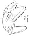
- FIG. 2shows a Nintendo N64 prior art game controller. This controller illustrates the growing need for variable or analog input control in the incorporation of the complex rotary encoder joystick. This controller has typical traditional right hand area depressible buttons and also a typical cross-shaped depressible rocker pad in the left hand area.
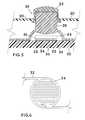
- FIG. 3shows a cross section view of a resilient dome cap mounted over a circuit board having a first and a second circuit trace including pressure-sensitive variable-conductance material in a sensor arrangement in accordance with the present invention.
- FIG. 4shows a top view of first and second conductive traces with finger-like traces laying opposed in proximity with one another.
- FIG. 5shows a cross sectional view of a resilient dome cap operatively associated with pressure-sensitive variable-conductance material atop interdigitated traces on a circuit board in accordance with the present invention.
- FIG. 6shows a top view of first and second interdigitated circuit traces.
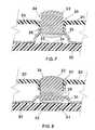
- FIG. 7shows a cross sectional view of a resilient dome cap supporting and operatively associated with pressure-sensitive variable-conductance material above interdigitated traces on a circuit board in accordance with the present invention.
- FIG. 8shows the sensor of FIG. 7 in a depressed or activated state.
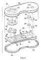
- FIG. 9shows an exploded view of one controller in accordance with the present invention.
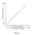
- FIG. 10is a graph illustrating depressive pressure in relation or in proportion to the conductivity of a pressure sensor, which typically corresponds to action intensity of imagery on the game display.
- FIG. 11shows a game controller of a traditional format in accordance with the present invention for example.
- the game controlleris shown connected by wires to an image generation machine (game console or personal computer) which drives a display such as a television or computer monitor.
- image generation machinegame console or personal computer
- the present inventionincludes a game controller which is a two hand held controller sized and shaped to be grasped and held simultaneously by two hands of a human user with thumbs of the grasping hands remaining substantially free of grasping responsibilities so as to be available and useful in depressing a plurality of depressible surfaces 22 each at least in-part exposed on housing 20 to be accessible by the user's digits.
- a game controllerwhich is a two hand held controller sized and shaped to be grasped and held simultaneously by two hands of a human user with thumbs of the grasping hands remaining substantially free of grasping responsibilities so as to be available and useful in depressing a plurality of depressible surfaces 22 each at least in-part exposed on housing 20 to be accessible by the user's digits.
- a plurality of electricity manipulating devices 24are contained (or at least in part contained) within housing 20 in operable association with the plurality of depressible surfaces 22 for manipulating electrical outputs with depression by the user's hand digits (thumbs or fingers) of the plurality of depressible surfaces 22 .
- Electricity manipulating devices 24 in this disclosurecan be any electrical device such as simple Off/On (momentary-On) switches as are commonly used in prior art game controllers, but with the present invention at least one of the electricity manipulating devices 24 is an analog pressure-sensitive variable-conductance sensor 26 for varying electrical output proportional to varying physical pressure applied by the user's thumb or fingers on a depressible surface 22 positioned to apply pressure to pressure-sensitive variable-conductance material 36 of sensor 26 as will be detailed.
- FIG. 3Shown in FIG. 3 is a pressure-sensitive variable-conductance sensor 26 or analog sensor as it may installed by a manufacturer within a game controller in accordance with the present invention.
- Resilient dome cap 28is shown made of rubbery material, such as injection molded silicone rubber, mounted over a circuit board 30 having a first circuit trace 32 and a second circuit trace 34 and including pressure-sensitive variable-conductance material 36 contacting both traces 32 , 34 , and an electrically conductive plate 38 is shown atop pressure-sensitive variable-conductance material 36 .
- An underside portion of depressible surface 22is shown atop dome cap 28 .
- Dome cap 28is a resilient dome providing a return spring lifting depressible surface 22 and provides or serves the purpose in this example of supporting depressible surface 22 raised upward until manually depressed to cause the lower or inner surface of dome cap 28 to press against plate 38 which in turn presses against pressure-sensitive variable-conductance material 36 which, as will be detailed, changes its conductivity with applied pressure to alter the conductance of the electrical path provided thereby between the first and second conductive traces 32 and 34 which are in close proximity to one another yet separated.
- Sensor 26can be used in replacement of a simple momentary-On switch within a game controller wherein a momentary-On switch simply closes the circuit across the first and second traces 32 and 34 while the user presses on depressible surface 22 and the closed circuit outputs a known and fixed output (On or Off, or open or closed), while with the application of sensor 26 depressing of depressible surface 22 provides variable electrical flow across the first and second circuit traces 32 , 34 varying in proportion to the degree of depressive pressure applied by the user's thumb or finger on the top or upper exposed portion of depressible surface 22 .
- Such an arrangementallows a voltage/current to be applied to first circuit trace 32 wherein current flows from first circuit trace 32 through pressure-sensitive variable-conductance material 36 into conductive plate 38 through pressure-sensitive variable-conductance material 36 and into second circuit trace 34 .
- Voltage/currentcan be regulated and varied by way of applied physical pressure such as onto plate 38 to compress material 36 which alters the conductivity of the circuit at least in-part defined by circuit traces 32 and 34 .
- Pressure-sensitive variable-conductance material 36is an important aspect of the present invention. Variable conductance can be achieved with materials having either variable resistive properties or variable rectifying properties.
- variable-conductancemeans either variably resistive or variably rectifying. Material having these qualities can be achieved utilizing various chemical compounds or formulas some of which I will herein detail for example. Additional information regarding such materials can be found in U.S. Pat. No. 3,806,471 issued to R. J. Mitchell on Apr. 23, 1974 describing various feasible pressure-sensitive variable-conductance material formulas which can be utilized in the present invention. While it is generally anticipated that variable resistive type active materials are optimum for use in the pressure sensor(s) in the present invention, variable rectifying materials are also usable.
- An example formula or compound having variable rectifying propertiescan be made of any one of the active materials copper oxide, magnesium silicide, magnesium stannide, cuprous sulfide, (or the like) bound together with a rubbery or elastic type binder having resilient qualities such as silicone adhesive or the like.
- An example formula or compound having variable resistive propertiescan be made of the active material tungsten carbide powder (or other suitable material such as molybdenum disulfide, sponge iron, tin oxide, boron, and carbon powders, etc.) bound together with a rubbery or elastic type binder such as silicone rubber or the like having resilient qualities.
- tungsten carbide powderor other suitable material such as molybdenum disulfide, sponge iron, tin oxide, boron, and carbon powders, etc.
- a rubbery or elastic type bindersuch as silicone rubber or the like having resilient qualities.
- the active materialsmay be in proportion to the binder material typically in a rich ratio such as 80% active material to 20% binder by volume ranging to a ratio 98% to 2% binder, but can be varied widely from these ratios dependant on factors such as voltages to be applied, level or resistance range desired, depressive pressure anticipated, material thickness of applied material 36 , surface contact area between material 36 and conductive traces such as traces 32 and 34 , whether an optional conductive plate such as plate 38 is to be used, binder type, manufacturing technique and specific active material used.
- a preferred method of manufacture for portions of that which is shown in FIG. 3is to create a sheet of pressure-sensitive material 36 adhered to a conductive sheet such as steel, aluminum or copper, for example, by applying a mixture of the still fluid material 36 , before the binder material has cured to the conductive sheet in a thin even layer.
- a hole punchis used to create circular disks of the lamination of the conductive sheet (plate 38 ) adhered to material 36 .
- the disksmay then be secured to the circuit board and in contact with circuit traces 32 and 34 . Securing may be accomplished with the use of adhesives such as the same binder such as silicone rubber or adhesive as used in the formula to make material 36 .
- Depressible surface 22can be a button 40 style depressible member such as shown in FIGS. 9 and 11, or depressible surface 22 can be an end portion of a four-way rocker or four-way key pad 42 as shown in FIGS. 9 and 11.
- depressible surface 22 and electricity manipulating device 24are herein described and shown as separate elements, but they are only necessarily separate in a functional sense (i.e., physical depressing function verses electrical controlling function).
- depressible surface 22 and electricity manipulating device 24may be structured as one part.
- the upper part of dome cap 28 protruding through housing 20could itself be exposed to contact by a hand digit to function as the depressible surface 22 as shown for example in FIGS. 7 and 8.
- FIG. 4shows first and second electrically conductive traces 32 , 34 with finger-like traces laying in proximity with one another which can be the form of the first and second conductive traces 32 , 34 of FIG. 3 .
- the spacings between the conductive finger-like trace elements shown in FIG. 4allow for adhesive which can be used to adhere a layer or disk of pressure-sensitive variable-conductance material 36 to circuit board 30 if so desired by the manufacturer.
- FIG. 5Shown in FIG. 5 is a second pressure-sensitive variable-conductance sensor 26 or analog sensor embodiment as it may be installed by a manufacturer within a game controller useful with the present invention.
- Resilient dome cap 28is mounted over circuit board 30 having first and second circuit traces 32 , 34 and including pressure-sensitive variable-conductance material 36 contacting both traces 32 , 34 .
- Optional plate 44is shown atop pressure-sensitive variable-conductance material 36 .
- An underside portion of depressible surface 22is shown atop dome cap 28 .
- Depressible surface 22is shown in-part supported by housing 20 , which in this example is housing 20 providing lateral support against the side of surface 22 and additionally with surface 22 including a lower flange abutting the underside of housing 20 and thereby being prevented from escaping housing 20 .
- Optional plate 44 in this arrangementcan be a stiff plate utilized as a physical load distributor to distribute compressive loads received from the underside of dome cap 28 with depression of depressible surface 22 across material 36 and not be an electrical conductor, or alternatively it can also be an electrical conductor dependant upon the particular thickness of material 36 and or spaced distance between circuit traces 32 and 34 beneath material 36 . Plate 44 does not have to be applied atop material 36 in all embodiments.
- Circumstances which effect the determination as to whether plate 44 or conductive plate 38 for that matter are used atop material 36include: the particular formula of material 36 ; dimensions of the applied material 36 ; the size, shaped proximity and layout of the circuit traces in contact with material 36 , and manufacturing considerations such as is material 36 directly applied to plate 44 or 38 in an easily handled disk and then adhered to the circuit board 30 , or applied directly to circuit board 30 and traces 32 , 34 such as by application in a fluid mixture (uncured) using a removable mask; or directly injected onto circuit board 30 such as with injection molding; or a pill/disk of material 36 is sliced from a cured cylinder or extrusion of material 36 and the pill/disk adhered to circuit board 30 and/or traces 32 , 34 ; and other manufacturing techniques.
- FIG. 6shows a top view of closely interdigitated circuit traces 32 and 34 in a form as may likely be used in the sensor structures shown in FIGS. 5, 7 and 8 .
- FIGS. 7 and 8Shown in FIGS. 7 and 8 is a third pressure-sensitive variable-conductance sensor 26 formed as a depressible individual button which is an analog sensor embodiment as it may be installed by a manufacturer within a game controller or used by a user of the game controller in accordance with the present invention.
- Rubber dome cap 28is mounted over circuit board 30 having first and second circuit traces 32 , 34 and including pressure-sensitive variable-conductance material 36 on the bottom side of resilient dome cap 28 .
- An upper exposed portion of dome cap 28is exposed exterior of housing 20 so that depression by a thumb or finger of depressible surface 22 causes downward movement or depression of dome cap 28 to bring material 36 into contact with traces 32 and 34 .
- Depressible surface 22is shown in-part supported or laterally stabilized by housing 20 .
- Material 36is not permanently contacting traces 32 and 34 as is shown in FIGS. 3 and 5, but instead is on the underside of dome cap 28 in pill or disk form and raised or held upward above traces 32 , 34 by dome cap 28 until, as indicated in FIG. 8, surface 22 is depressed to push dome cap 28 downward to bring material 36 into contact with traces 32 , 34 which, under pressure, establishes a conductive path across traces 32 , 34 .
- FIGS. 7 and 8is the surface of material 36 which contacts traces 32 and 34 is convexed which in this particular application provides for the apex of the surface to first contact across traces 32 and 34 followed by material 36 which is flexible deforming with additional applied pressure to somewhat flatten-out and contact additional surface area of both traces 32 and 34 .
- This arrangement of relatively lower initial surface area contact followed by additional or a larger surface area contact with further depressioncan provide additional conductivity changes due to not only the inherent conductivity changes brought about by pressure applied to material 36 but also by establishing additional current paths possible by the additional surface contact area.
- Material 36 in FIGS. 7 and 8can be formed with a flat bottom surface and function adequately without the increasing surface area effect provided by the convexed shape shown. Additionally sensors 26 of FIGS. 3, 5 , 7 and 8 will function within the scope of the invention absent the spring return effect of dome cap 28 wherein material 36 shown in FIG. 7 would be resting upon traces 32 and 34 and actuated by depression of surface 22 .
- a carbon-rich conductive pill or diskis located on the underside of a typical dome cap such as dome cap 28 .
- carbon-rich conductive pillsare employed as simple On/Off momentary-On switches wherein the pill is depressed by the user onto and across circuit traces to close the circuit and released to open the circuit.
- the carbon-rich pillis a component of a switch that is only an On/Off switch.
- the prior art carbon-rich conductive pillis commonly used exclusively as an improved On/Off switch with the improvement being that this is considered a bounce-less switch not subjecting the circuitry to rapid on/off oscillations at the time of initial depression.
- Carbon-rich pillsare typically made of granular carbon in high concentrations in a silicone rubber binder producing a resilient conductive material resistant to mechanical bouncing when depressed onto a surface.
- the carbon-rich pillis utilized to advantage in a simple On/Off bounce-less switch.
- Such a carbon-rich pillto my knowledge, has never been used or anticipated to be used for an analog sensor to provide action intensity control of electronic imagery. Neither, to my knowledge, has such a carbon-rich pill ever been used or anticipated to be used for an analog sensor in a two hand held game controller. I have discovered that such a carbon-rich pill or disk can be used, in a novel manner as taught herein, as an analog sensor in a game controller to provide action intensity control of electronic imagery such as that associated with electronic games. However, a narrow range of resistivity change found in a typical prior art carbon-rich pill as a function of depressive pressure exerted makes it not an ideal choice as an analog sensor in a human hand operated controller.
- a carbon-rich pill as a variable resistormay typically have a range of resistance from a high value of approximately 3 thousand ohms to a low value near 10 ohms, which is a narrow range compared to a tungsten carbide based material 36 which may typically have a range from approximately 3 million ohms down to a low of approximately 10 ohms.
- the tungsten carbide based material 36has a range of nearly 3 million ohms, while the carbon-rich pill has a range of nearly 3 thousand ohms, resulting in an improvement of three magnitudes (i.e., one thousand times) in range of the tungsten carbide material 36 over the carbon-rich pill.
- Tungsten carbide having an extreme resistance range as a function of physical depressive pressureallows for greater variation (higher resolution) of physical pressure applied within those levels normal to light use by the thumb or finger of a typical human user.
- the variable resistance range of tungsten carbideis additionally quite stable over a wide temperature range.
- Tungsten carbidealso has excellent wear characteristics and minimal hysteresis. Therefore, tungsten carbide is a preferred active material for use with the present invention.
- material 36can be manufactured and fixed in place with numerous processes not yet detailed, and for example, tungsten carbide can be mixed with un-crosslinked silicone rubber and extruded from a tool or pressed into a cylindrical mold, allowed to crosslink, and then cut or sliced into disks or pills of material 36 which can then be placed in appropriate location to circuit traces 32 , 34 or on dome cap 28 .
- tungsten carbidecan be mixed with un-crosslinked silicone rubber and extruded from a tool or pressed into a cylindrical mold, allowed to crosslink, and then cut or sliced into disks or pills of material 36 which can then be placed in appropriate location to circuit traces 32 , 34 or on dome cap 28 .
- Another processis to mix tungsten carbide or other suitable material with an injection moldable silicone rubber and then inject the material onto any desireable surface such as a membrane surface such as mylar, or circuit board 30 and traces 32 , 34 , or using an injection process for creating dome cap 28 with disks or pills of material 36 thereon, such as could be performed for the dome cap 28 and material 36 arrangement of FIGS. 7 and 8, or dome cap 28 can be a flexible/resilient dome cap and material 36 can be molded either onto the dome cap or onto the circuit board, etc.
- one circuit tracesuch as trace 32 can make electrical contact with a foot of the dome cap and the second trace below the approximate center of the dome cap with material 36 positioned between the second trace and the center of the dome cap such that depression of the dome cap effectively sandwiches material 36 .
- FIG. 9shows an exploded view of a controller in accordance with one embodiment of the present invention. Shown at the top of the view is an upper portion 50 of housing 20 .
- Upper portion 50 of housing 20includes on the right hand side a pair of circular holes 52 for receiving and in-part supporting (retaining) depressible surfaces 22 which in this example are buttons 40 .
- On the left hand side of the housing topis a cross-shaped opening 54 through the housing for in-part receiving and supporting a four-way rocker 42 which is a depressible surface 22 .
- the depressible surfaces when assembled into the housingare in-part exposed on the housing surface for depressing by the digits of the human hands. Shown below the housing upper portion 50 is rocker 42 and buttons 40 .
- circuit board 30Shown beneath the rubber dome caps is circuit board 30 having on its left side an array of circuit traces forming four areas including adjacent circuit traces 32 and 34 in close proximity to one another for operative engagement with material 36 installed by the manufacturer atop each of the four areas which are located such that the four-gang rubber dome cap can be applied over the four locations of material 36 to provide a dome cap over each material 36 location.
- Rocker 42can then be located atop the four-gang rubber dome cap so that one dome cap is located underneath each one of the four arm structures (four codependant areas) of rocker 42 . Each arm of rocker 42 is placed one arm above each of the four locations of material 36 .
- Rocker 42is supported elevated above material 36 by dome caps, and when housing 20 is fully assembled with a lower portion 56 of housing, a flange 58 on the lower outward edge of rocker 42 prevents rocker 42 from completely passing through cross-shaped hole 54 .
- Shown on the right side of circuit board 30are two locations of applied material 36 installed by the manufacturer over separated yet in close proximity to circuit traces 32 and 34 .
- the two individual dome caps 28will be placed one over each material 36 location of the right side of the board 30 , and button 40 positioned onto dome caps 28 , the upper surfaces of buttons 40 positioned through holes 52 and housing 20 and circuit board 30 connected to one another and housing 20 closed with upper portion 50 and lower portion 56 affixed together.
- circuit board 30Also shown on circuit board 30 is circuit traces 32 and 34 connecting to active electronics 46 installed by the manufacturer and electronics 46 having the capacity to output a signal at least representational of the analog electrical output of pressure-sensitive variable-conductance sensor(s) 26 into output cable 48 leading to an image generation machine 60 such as a game console or computer connected to a display (FIG. 11 ).
- Active electronics 46i.e., ASIC or micro-controller integrated circuity, etc.
- ASICapplication-controller integrated circuity, etc.
- circuit traces 32 and 34could simply be connected directly to conductors of cable 48 for outputting a signal at least representational of the analog electrical output of pressure-sensitive variable-conductance sensor(s) 26 through output cable 48 into an image generation machine 60 wherein active electronics 46 may be located.
- FIG. 10shows an idealized graph indicating conductivity of pressure-sensitive variable-conductance sensor such as sensor 26 and the corresponding action intensity of imagery in a game machine as a function of depressive pressure exerted by the thumb or fingers (digit) onto the depressible surfaces of a game controller as herein described.
- the graphshows that with a low depressive pressure, the conductivity is also low (resistivity high), and action intensity of imagery would normally be arranged to be low since the typical user will normally naturally associate low applied pressure with low action intensity.
- As depressive pressure increasesso also increases the conductivity (resistivity lowering) proportionally in a smooth continuous change or analog manner so as to provide a variable electrical output.
- Examples of typical left thumb use of the invention in a gamecan be to simply have a simulated character shown on the display walk with low depressive pressure applied to a depressible surface 22 of sensor 26 , walk faster with increased depressive pressure applied to the depressible surface 22 , and run with a relatively high depressive pressure applied to the same depressible surface 22 , with this being an example of controlling or changing the action intensity of the imagery proportionally with changes in depressive pressure applied to depressible surface 22 of sensor 26 .
- the usercan choose the action intensity of imagery by applying appropriate depressive pressure.
- a race carcan veer slightly with a low depressive pressure applied to surface 22 of sensor 26 and turn sharply with a high depressive pressure applied to the same depressible surface 22 .
- variable depressive pressurecan control variable fire rate of a gun or variable jumping height of a character shown as an image on display 62 .
- the invention in combination with an electronic game console or PC and displaycan be arranged so the action intensity of the imagery is reduced proportionally to increases or increasing depressive pressure applied on depressible surface 22 of sensor 26 wherein a simulated race car shown on the display travels at a high rate with little or no depressive pressure applied to surface 22 , and is slowed proportionally to increased or increasing depressive pressure applied by the user to the depressible surface 22 of sensor 26 , an arrangement wherein the sensor 26 is applied as a braking system.
- FIG. 11shows a game controller of a traditional format in accordance with the present invention for example.
- the game controlleris shown connected by cable 48 to an image generation machine 60 such as a game console or personal computer which drives a display 62 such as a television, computer monitor or head-mount display, etc.
- an image generation machine 60such as a game console or personal computer which drives a display 62 such as a television, computer monitor or head-mount display, etc.
Landscapes
- Engineering & Computer Science (AREA)
- General Engineering & Computer Science (AREA)
- Theoretical Computer Science (AREA)
- Human Computer Interaction (AREA)
- Physics & Mathematics (AREA)
- General Physics & Mathematics (AREA)
- Multimedia (AREA)
- Position Input By Displaying (AREA)
- Switches With Compound Operations (AREA)
- Push-Button Switches (AREA)
Abstract
Description
Claims (74)
Priority Applications (3)
| Application Number | Priority Date | Filing Date | Title |
|---|---|---|---|
| US09/510,572US6343991B1 (en) | 1997-10-01 | 2000-02-22 | Game control with analog pressure sensor |
| US09/729,753US20010008848A1 (en) | 1997-10-01 | 2000-11-30 | Controller with convexed surface analog pressure sensor |
| US09/893,292US7345670B2 (en) | 1992-03-05 | 2001-06-26 | Image controller |
Applications Claiming Priority (2)
| Application Number | Priority Date | Filing Date | Title |
|---|---|---|---|
| US08/942,450US6102802A (en) | 1997-10-01 | 1997-10-01 | Game controller with analog pressure sensor(s) |
| US09/510,572US6343991B1 (en) | 1997-10-01 | 2000-02-22 | Game control with analog pressure sensor |
Related Parent Applications (1)
| Application Number | Title | Priority Date | Filing Date |
|---|---|---|---|
| US08/942,450ContinuationUS6102802A (en) | 1992-03-05 | 1997-10-01 | Game controller with analog pressure sensor(s) |
Related Child Applications (2)
| Application Number | Title | Priority Date | Filing Date |
|---|---|---|---|
| US71055700AContinuation-In-Part | 1992-03-05 | 2000-11-08 | |
| US09/729,753ContinuationUS20010008848A1 (en) | 1997-10-01 | 2000-11-30 | Controller with convexed surface analog pressure sensor |
Publications (1)
| Publication Number | Publication Date |
|---|---|
| US6343991B1true US6343991B1 (en) | 2002-02-05 |
Family
ID=25478082
Family Applications (3)
| Application Number | Title | Priority Date | Filing Date |
|---|---|---|---|
| US09/510,572Expired - LifetimeUS6343991B1 (en) | 1992-03-05 | 2000-02-22 | Game control with analog pressure sensor |
| US09/729,753AbandonedUS20010008848A1 (en) | 1997-10-01 | 2000-11-30 | Controller with convexed surface analog pressure sensor |
| US09/896,680AbandonedUS20020019259A1 (en) | 1997-10-01 | 2001-06-29 | Controller with analog pressure sensor (s) |
Family Applications After (2)
| Application Number | Title | Priority Date | Filing Date |
|---|---|---|---|
| US09/729,753AbandonedUS20010008848A1 (en) | 1997-10-01 | 2000-11-30 | Controller with convexed surface analog pressure sensor |
| US09/896,680AbandonedUS20020019259A1 (en) | 1997-10-01 | 2001-06-29 | Controller with analog pressure sensor (s) |
Country Status (1)
| Country | Link |
|---|---|
| US (3) | US6343991B1 (en) |
Cited By (32)
| Publication number | Priority date | Publication date | Assignee | Title |
|---|---|---|---|---|
| US20020019259A1 (en)* | 1997-10-01 | 2002-02-14 | Armstrong Brad A. | Controller with analog pressure sensor (s) |
| US6524187B2 (en)* | 2000-01-14 | 2003-02-25 | Sony Computer Entertainment Inc. | Computer, method and recording medium for executing games using a pressure-sensitive controller |
| US6530839B2 (en)* | 2000-07-17 | 2003-03-11 | Konami Corporation | Game device, method of controlling game machine, information storage medium, and program distribution device and method |
| US20030064764A1 (en)* | 2001-10-02 | 2003-04-03 | Konami Corporation | Game device, game control method and program |
| US20030193416A1 (en)* | 1999-04-23 | 2003-10-16 | Sony Computer Entertainment Inc. | Operating device |
| US20040160414A1 (en)* | 1996-07-05 | 2004-08-19 | Armstrong Brad A. | Image controller |
| US20050057514A1 (en)* | 2003-09-16 | 2005-03-17 | Microsoft Corporation | Quantitatively force-sensing computer keyboard |
| US20050057515A1 (en)* | 2003-09-16 | 2005-03-17 | Microsoft Corporation | Computer keyboard with quantitatively force-sensing keys |
| US20050057521A1 (en)* | 2003-09-16 | 2005-03-17 | Microsoft Corporation | Method for processing data quantifying force applied to one or more keys of a computer keyboard |
| US20050114142A1 (en)* | 2003-11-20 | 2005-05-26 | Masamichi Asukai | Emotion calculating apparatus and method and mobile communication apparatus |
| US6906700B1 (en) | 1992-03-05 | 2005-06-14 | Anascape | 3D controller with vibration |
| US6923717B2 (en)* | 2001-05-15 | 2005-08-02 | Nintendo Of America Inc. | Adrenaline feature for sports video games |
| US6929547B2 (en)* | 2000-01-14 | 2005-08-16 | Sony Computer Entertainment Inc. | Recording medium, method of using a computer and computer for executing role-playing games |
| US20050231476A1 (en)* | 1996-07-05 | 2005-10-20 | Armstrong Brad A | Image controller |
| US20060022939A1 (en)* | 1992-03-05 | 2006-02-02 | Armstrong Brad A | Image controller |
| US20080000765A1 (en)* | 2006-06-28 | 2008-01-03 | Altek Corporation | Composite switch |
| US20080266254A1 (en)* | 2007-04-24 | 2008-10-30 | Irobot Corporation | Control System for a Remote Vehicle |
| US20100167820A1 (en)* | 2008-12-29 | 2010-07-01 | Houssam Barakat | Human interface device |
| USD646050S1 (en)* | 2008-03-27 | 2011-10-04 | The Timberland Company | Footwear tread |
| US20120152037A1 (en)* | 2010-12-15 | 2012-06-21 | Honeywell International Inc. | Force sensor |
| US8396611B2 (en) | 2006-07-14 | 2013-03-12 | Irobot Corporation | Autonomous behaviors for a remote vehicle |
| US8806964B2 (en) | 2012-03-23 | 2014-08-19 | Honeywell International Inc. | Force sensor |
| US9003899B2 (en) | 2012-03-23 | 2015-04-14 | Honeywell International Inc. | Force sensor |
| US9003897B2 (en) | 2012-05-10 | 2015-04-14 | Honeywell International Inc. | Temperature compensated force sensor |
| US9266022B1 (en) | 2012-08-21 | 2016-02-23 | David Paul Pasqualone | System to pause a game console whenever an object enters an exclusion zone |
| USD845595S1 (en) | 2014-12-19 | 2019-04-16 | Dansko, Llc | Shoe sole |
| US10274627B2 (en) | 2015-10-30 | 2019-04-30 | Ion Geophysical Corporation | Ocean bottom seismic systems |
| USD854172S1 (en)* | 2016-12-31 | 2019-07-16 | Woori Material Inc. | Cast |
| US20200155941A1 (en)* | 2017-09-15 | 2020-05-21 | KABUSHIKI KAISHA SEGA Games doing business as SEGA Game Co., Ltd. | Information processing device and method of causing computer to perform game program |
| US11204365B2 (en) | 2018-09-13 | 2021-12-21 | Ion Geophysical Corporation | Multi-axis, single mass accelerometer |
| US20220305377A1 (en)* | 2021-03-25 | 2022-09-29 | Sony Interactive Entertainment Inc. | Inputting device |
| US11524224B2 (en)* | 2019-11-19 | 2022-12-13 | Sony Interactive Entertainment Inc. | Operating device |
Families Citing this family (21)
| Publication number | Priority date | Publication date | Assignee | Title |
|---|---|---|---|---|
| US6615814B1 (en)* | 1999-03-18 | 2003-09-09 | Npf Limited | Paintball guns |
| US6311682B1 (en) | 1999-01-22 | 2001-11-06 | Npf Limited | Paintball guns |
| US7218313B2 (en) | 2003-10-31 | 2007-05-15 | Zeetoo, Inc. | Human interface system |
| WO2006007561A2 (en)* | 2004-07-01 | 2006-01-19 | Geltabz, Inc. | Joystick cover |
| USD540395S1 (en) | 2005-07-01 | 2007-04-10 | Geltabz, Inc. | Joystick cover |
| DE112007003554A5 (en)* | 2007-04-20 | 2010-04-08 | Siemens Aktiengesellschaft | Switching element and / or control element |
| WO2009036375A1 (en)* | 2007-09-14 | 2009-03-19 | Panasonic Avionics Corporation | Portable user control device and method for vehicle information systems |
| US8727878B2 (en)* | 2008-07-18 | 2014-05-20 | Disney Enterprises, Inc. | Video game controller |
| US8172675B2 (en)* | 2009-03-27 | 2012-05-08 | Microsoft Corporation | Personalization using a hand-pressure signature |
| US9740340B1 (en)* | 2009-07-31 | 2017-08-22 | Amazon Technologies, Inc. | Visually consistent arrays including conductive mesh |
| US8535133B2 (en)* | 2009-11-16 | 2013-09-17 | Broadcom Corporation | Video game with controller sensing player inappropriate activity |
| US8641525B2 (en)* | 2011-06-17 | 2014-02-04 | Ironburg Inventions Ltd. | Controller for video game console |
| US10203768B2 (en)* | 2013-09-20 | 2019-02-12 | Franklin Donald Ruffin | Blind key pad |
| CN107105918B (en)* | 2014-12-24 | 2019-09-27 | 雀巢产品有限公司 | Beverage preparing machine |
| US10124249B2 (en) | 2015-05-01 | 2018-11-13 | Microsoft Technology Licensing, Llc | Game controller with removable controller accessory |
| US9898091B2 (en) | 2015-06-03 | 2018-02-20 | Oculus Vr, Llc | Virtual reality system with head-mounted display, camera and hand-held controllers |
| US10137364B2 (en)* | 2015-06-09 | 2018-11-27 | Microsoft Technology Licensing, Llc | Game controller with removable magnetic button |
| US9870052B2 (en) | 2015-06-11 | 2018-01-16 | Oculus Vr, Llc | Hand-held controller with pressure-sensing switch for virtual-reality systems |
| CN105891706B (en)* | 2016-03-30 | 2018-12-25 | 北京小米移动软件有限公司 | The calibration method and device of distant bar on remote control equipment |
| CN106237612A (en)* | 2016-07-25 | 2016-12-21 | 乐视控股(北京)有限公司 | motion recognition system and method |
| GB2588581B (en)* | 2019-10-14 | 2022-09-21 | Focusrite Audio Engineering Ltd | Button |
Citations (14)
| Publication number | Priority date | Publication date | Assignee | Title |
|---|---|---|---|---|
| US3806471A (en) | 1968-04-29 | 1974-04-23 | R Mitchell | Pressure responsive resistive material |
| US4469330A (en) | 1982-01-07 | 1984-09-04 | Atari, Inc. | Controller unit for video game |
| US4687200A (en) | 1983-08-05 | 1987-08-18 | Nintendo Co., Ltd. | Multi-directional switch |
| JPH0587760A (en) | 1991-03-18 | 1993-04-06 | Toto Ltd | Gas sensor and production thereof |
| US5207426A (en) | 1990-08-09 | 1993-05-04 | Nintendo Co. Ltd. | Controller for a game machine |
| US5459487A (en) | 1992-07-09 | 1995-10-17 | Thrustmaster, Inc. | Video game/flight simulator controller with single analog input to multiple discrete inputs |
| JPH07302159A (en) | 1994-04-28 | 1995-11-14 | Sega Enterp Ltd | Switch device |
| US5510812A (en) | 1994-04-22 | 1996-04-23 | Hasbro, Inc. | Piezoresistive input device |
| US5565891A (en) | 1992-03-05 | 1996-10-15 | Armstrong; Brad A. | Six degrees of freedom graphics controller |
| US5602569A (en) | 1994-04-28 | 1997-02-11 | Nintendo Co., Ltd. | Controller for image processing apparatus |
| US5644113A (en) | 1995-01-03 | 1997-07-01 | Sega Eenterprises, Ltd. | Hand held control key device including multiple switch arrangements |
| US5689285A (en) | 1993-09-13 | 1997-11-18 | Asher; David J. | Joystick with membrane sensor |
| US5764219A (en) | 1992-09-25 | 1998-06-09 | Ibm Corporation | Controller for improved computer pointing devices |
| US5999084A (en) | 1998-06-29 | 1999-12-07 | Armstrong; Brad A. | Variable-conductance sensor |
Family Cites Families (92)
| Publication number | Priority date | Publication date | Assignee | Title |
|---|---|---|---|---|
| FR1366051A (en)* | 1963-05-09 | 1964-07-10 | Telemecanique Electrique | Multi-directional single lever control device, especially for switches with combined movements |
| US3710050A (en)* | 1970-09-14 | 1973-01-09 | A Richards | Electronic pressure sensitive switch |
| JPS5073880U (en)* | 1973-11-09 | 1975-06-28 | ||
| JPS5244612A (en)* | 1975-10-03 | 1977-04-07 | Matsushita Electric Ind Co Ltd | Magnetic recording reproducing device |
| US4246452A (en)* | 1979-01-05 | 1981-01-20 | Mattel, Inc. | Switch apparatus |
| US4314228A (en)* | 1980-04-16 | 1982-02-02 | Eventoff Franklin Neal | Pressure transducer |
| US4315238A (en)* | 1979-09-24 | 1982-02-09 | Eventoff Franklin Neal | Bounceless switch apparatus |
| US4314227A (en)* | 1979-09-24 | 1982-02-02 | Eventoff Franklin Neal | Electronic pressure sensitive transducer apparatus |
| US4323888A (en)* | 1979-12-21 | 1982-04-06 | Megadata Corporation | Keyboard system with variable automatic repeat capability |
| IT1129409B (en)* | 1980-03-07 | 1986-06-04 | Fiat Ricerche | SIX DEGREE TRANSDUCER OF FREEDOM TO CONVERT INTO ELECTRIC SIGNALS THE FORCES AND MOMENTS APPLIED TO A MOBILE BODY PARTICULARLY TO THE MOBILE ARM OF A ROBOT |
| US4313113A (en)* | 1980-03-24 | 1982-01-26 | Xerox Corporation | Cursor control |
| US4369971A (en)* | 1981-01-07 | 1983-01-25 | Mattel, Inc. | Electronic bowling game |
| US4504059A (en)* | 1982-09-30 | 1985-03-12 | Weinrieb Steven W | Support apparatus for video game joystick control unit |
| US4491325A (en)* | 1983-01-26 | 1985-01-01 | Thomas Bersheim | Game control apparatus |
| GB8302094D0 (en)* | 1983-01-26 | 1983-03-02 | Int Computers Ltd | Data display control |
| US4573682A (en)* | 1983-02-24 | 1986-03-04 | Louis J. Conque | Joy stick holder |
| US4733214A (en)* | 1983-05-23 | 1988-03-22 | Andresen Herman J | Multi-directional controller having resiliently biased cam and cam follower for tactile feedback |
| US4514600A (en)* | 1983-11-14 | 1985-04-30 | North American Philips Corporation | Video game hand controller |
| JPH0735908B2 (en)* | 1984-07-11 | 1995-04-19 | シャープ株式会社 | microwave |
| US5103404A (en)* | 1985-12-06 | 1992-04-07 | Tensor Development, Inc. | Feedback for a manipulator |
| US4811608A (en)* | 1985-12-18 | 1989-03-14 | Spatial Systems Pty Limited | Force and torque converter |
| US5591924A (en)* | 1985-12-18 | 1997-01-07 | Spacetec Imc Corporation | Force and torque converter |
| US5706027A (en)* | 1985-12-18 | 1998-01-06 | Spacetec Imc Corporation | Force and torque converter for use in a computer input device |
| US4910503A (en)* | 1987-06-15 | 1990-03-20 | Brodsky Stephen L | Multi-function input device and system |
| US5182796A (en)* | 1988-03-23 | 1993-01-26 | Fuji Xerox Co., Ltd. | Multi-screen setting condition display system |
| US4909514A (en)* | 1988-10-24 | 1990-03-20 | Tano Robert S | Holder for manual video game controller toggle switch mechanisms |
| US5184830A (en)* | 1989-01-10 | 1993-02-09 | Nintendo Company Limited | Compact hand-held video game system |
| US5196782A (en)* | 1989-06-28 | 1993-03-23 | Lutron Electronics Co., Inc. | Touch-operated power control |
| US6040821A (en)* | 1989-09-26 | 2000-03-21 | Incontrol Solutions, Inc. | Cursor tracking |
| US5231386A (en)* | 1990-07-24 | 1993-07-27 | Home Row, Inc. | Keyswitch-integrated pointing assembly |
| US5183998A (en)* | 1990-05-30 | 1993-02-02 | Mr. Coffee Inc. | Apparatus and method for heating water for infusion and the like |
| US5541622A (en)* | 1990-07-24 | 1996-07-30 | Incontrol Solutions, Inc. | Miniature isometric joystick |
| US5103498A (en)* | 1990-08-02 | 1992-04-07 | Tandy Corporation | Intelligent help system |
| US5396235A (en)* | 1990-09-05 | 1995-03-07 | Canon Kabushiki Kaisha | Numeral setting apparatus |
| JPH04176235A (en)* | 1990-11-08 | 1992-06-23 | Nintendo Co Ltd | Communication adaptor for game machine |
| US5200597A (en)* | 1991-02-07 | 1993-04-06 | Psc, Inc. | Digitally controlled system for scanning and reading bar codes |
| US5278557A (en)* | 1991-02-19 | 1994-01-11 | Key Tronic Corporation | Cursor movement control key and electronic computer keyboard for computers having a video display |
| US5714983A (en)* | 1991-02-20 | 1998-02-03 | Sacks; Robert | Interactive computer system with controllable rate repetition of computer actions in response to operator inputs |
| US5286024A (en)* | 1991-03-20 | 1994-02-15 | Atari Games Corporation | System for sensing the position of a joystick |
| US5203563A (en)* | 1991-03-21 | 1993-04-20 | Atari Games Corporation | Shaker control device |
| US5184120A (en)* | 1991-04-04 | 1993-02-02 | Motorola, Inc. | Menu selection using adaptive force sensing resistor |
| US5298919A (en)* | 1991-08-02 | 1994-03-29 | Multipoint Technology Corporation | Multi-dimensional input device |
| AU667688B2 (en)* | 1991-10-04 | 1996-04-04 | Micromed Systems, Inc. | Hand held computer input apparatus and method |
| US6344791B1 (en)* | 1998-07-24 | 2002-02-05 | Brad A. Armstrong | Variable sensor with tactile feedback |
| US6208271B1 (en)* | 1998-09-04 | 2001-03-27 | Brad A. Armstrong | Remote controller with analog button(s) |
| US6343991B1 (en)* | 1997-10-01 | 2002-02-05 | Brad A. Armstrong | Game control with analog pressure sensor |
| US6347997B1 (en)* | 1997-10-01 | 2002-02-19 | Brad A. Armstrong | Analog controls housed with electronic displays |
| US5189355A (en)* | 1992-04-10 | 1993-02-23 | Ampex Corporation | Interactive rotary controller system with tactile feedback |
| US5508719A (en)* | 1992-05-01 | 1996-04-16 | Ast Research, Inc. | Pressure-actuated pointing device |
| US5293158A (en)* | 1992-05-05 | 1994-03-08 | Alps Electric Co., Ltd. | X-Y direction input device |
| US5287089A (en)* | 1992-05-13 | 1994-02-15 | Micro-Integration Corporation | Hand manipulatable computer input device |
| US5889236A (en)* | 1992-06-08 | 1999-03-30 | Synaptics Incorporated | Pressure sensitive scrollbar feature |
| US5861583A (en)* | 1992-06-08 | 1999-01-19 | Synaptics, Incorporated | Object position detector |
| US5880411A (en)* | 1992-06-08 | 1999-03-09 | Synaptics, Incorporated | Object position detector with edge motion feature and gesture recognition |
| US5488204A (en)* | 1992-06-08 | 1996-01-30 | Synaptics, Incorporated | Paintbrush stylus for capacitive touch sensor pad |
| DE69324067T2 (en)* | 1992-06-08 | 1999-07-15 | Synaptics Inc | Object position detector |
| US6028271A (en)* | 1992-06-08 | 2000-02-22 | Synaptics, Inc. | Object position detector with edge motion feature and gesture recognition |
| US5280926A (en)* | 1992-07-14 | 1994-01-25 | Texas Instruments Incorporated | Seal apparatus for pressure responsive electrical switch |
| US5392337A (en)* | 1993-01-04 | 1995-02-21 | At&T Corp. | Arrangement for varying the display time for messages displayable on a telephone terminal |
| US5394168A (en)* | 1993-01-06 | 1995-02-28 | Smith Engineering | Dual-mode hand-held game controller |
| GB2278729A (en)* | 1993-06-04 | 1994-12-07 | Txc Corp | Direction control key assembly |
| US5389757A (en)* | 1993-06-15 | 1995-02-14 | Digital Equipment Corporation | Elastomeric key switch actuator |
| US5386084A (en)* | 1993-07-22 | 1995-01-31 | Ii Morrow Inc. | Electronic device enclosure |
| US5381388A (en)* | 1993-07-28 | 1995-01-10 | Technomarket, L.P. | Digital clock |
| USD355901S (en)* | 1993-08-06 | 1995-02-28 | Logitech, Inc. | Computer mouse |
| US5537212A (en)* | 1993-10-12 | 1996-07-16 | Lazer-Tron Corporation | Method and apparatus for sensing the color of an object |
| US5399823A (en)* | 1993-11-10 | 1995-03-21 | Minimed Inc. | Membrane dome switch with tactile feel regulator shim |
| JP2584201B2 (en)* | 1994-01-14 | 1997-02-26 | インターナショナル・ビジネス・マシーンズ・コーポレイション | Power transducer, computer system and keyboard |
| US5606594A (en)* | 1994-01-27 | 1997-02-25 | Dell Usa, L.P. | Communication accessory and method of telecommunicating for a PDA |
| US5391083A (en)* | 1994-02-25 | 1995-02-21 | R. A. Tool & Die, Inc. | Computer card connector |
| KR100354937B1 (en)* | 1994-04-15 | 2002-12-26 | 코닌클리케 필립스 일렉트로닉스 엔.브이. | Video signal transmission and reception device and method |
| MY118477A (en)* | 1994-04-20 | 2004-11-30 | Sony Corp | Communication terminal apparatus and control method thereof |
| JP3628358B2 (en)* | 1994-05-09 | 2005-03-09 | 株式会社ソニー・コンピュータエンタテインメント | Game console controller |
| GB2295662A (en)* | 1994-11-28 | 1996-06-05 | Wah Leung Chan | Joystick eg for video games |
| TW366674B (en)* | 1995-08-30 | 1999-08-11 | Motorola Inc | Method and apparatus for marking messages in selective call receivers |
| US5615083A (en)* | 1995-12-11 | 1997-03-25 | Gateway 2000, Inc. | Detachable joystick for a portable computer |
| US6351205B1 (en)* | 1996-07-05 | 2002-02-26 | Brad A. Armstrong | Variable-conductance sensor |
| JP3732281B2 (en)* | 1996-08-30 | 2006-01-05 | シチズン時計株式会社 | Multifunction clock |
| US6028531A (en)* | 1996-10-21 | 2000-02-22 | Wanderlich; Ronald E. | Terminal units for a mobile communications system |
| US6177926B1 (en)* | 1996-10-22 | 2001-01-23 | Intermec Ip Corp. | Hand-held computer having input screen and means for preventing inadvertent actuation of keys |
| US5796393A (en)* | 1996-11-08 | 1998-08-18 | Compuserve Incorporated | System for intergrating an on-line service community with a foreign service |
| US5883619A (en)* | 1996-11-12 | 1999-03-16 | Primax Electronics Ltd. | Computer mouse for scrolling a view of an image |
| US6178338B1 (en)* | 1997-04-28 | 2001-01-23 | Sony Corporation | Communication terminal apparatus and method for selecting options using a dial shuttle |
| US6031516A (en)* | 1997-07-03 | 2000-02-29 | Leiper; Thomas W. | Integrated film and filmless image display system |
| US6037954A (en)* | 1997-07-23 | 2000-03-14 | Mcmahon; M. James | Portable hand-held reading device |
| US6532000B2 (en)* | 1997-10-01 | 2003-03-11 | Brad A. Armstrong | Analog controls housed with electronic displays for global positioning systems |
| US6027828A (en)* | 1997-10-16 | 2000-02-22 | Advanced Mobile Solutions, Inc. | Modular stackable battery pack and accessories |
| AU6040999A (en)* | 1998-09-14 | 2000-04-03 | Microsoft Corporation | Input device with forward/backward control |
| US6198472B1 (en)* | 1998-09-16 | 2001-03-06 | International Business Machines Corporation | System integrated 2-dimensional and 3-dimensional input device |
| US6198473B1 (en)* | 1998-10-06 | 2001-03-06 | Brad A. Armstrong | Computer mouse with enhance control button (s) |
| JP2001043012A (en)* | 1999-07-27 | 2001-02-16 | Alps Electric Co Ltd | Signal input device |
| TW575453B (en)* | 2000-01-14 | 2004-02-11 | Sony Computer Entertainment Inc | Computer, method and recording medium for executing games using a pressure-sensitive controller |
- 2000
- 2000-02-22USUS09/510,572patent/US6343991B1/ennot_activeExpired - Lifetime
- 2000-11-30USUS09/729,753patent/US20010008848A1/ennot_activeAbandoned
- 2001
- 2001-06-29USUS09/896,680patent/US20020019259A1/ennot_activeAbandoned
Patent Citations (15)
| Publication number | Priority date | Publication date | Assignee | Title |
|---|---|---|---|---|
| US3806471A (en) | 1968-04-29 | 1974-04-23 | R Mitchell | Pressure responsive resistive material |
| US4469330A (en) | 1982-01-07 | 1984-09-04 | Atari, Inc. | Controller unit for video game |
| US4687200A (en) | 1983-08-05 | 1987-08-18 | Nintendo Co., Ltd. | Multi-directional switch |
| US5207426A (en) | 1990-08-09 | 1993-05-04 | Nintendo Co. Ltd. | Controller for a game machine |
| JPH0587760A (en) | 1991-03-18 | 1993-04-06 | Toto Ltd | Gas sensor and production thereof |
| US5589828A (en) | 1992-03-05 | 1996-12-31 | Armstrong; Brad A. | 6 Degrees of freedom controller with capability of tactile feedback |
| US5565891A (en) | 1992-03-05 | 1996-10-15 | Armstrong; Brad A. | Six degrees of freedom graphics controller |
| US5459487A (en) | 1992-07-09 | 1995-10-17 | Thrustmaster, Inc. | Video game/flight simulator controller with single analog input to multiple discrete inputs |
| US5764219A (en) | 1992-09-25 | 1998-06-09 | Ibm Corporation | Controller for improved computer pointing devices |
| US5689285A (en) | 1993-09-13 | 1997-11-18 | Asher; David J. | Joystick with membrane sensor |
| US5510812A (en) | 1994-04-22 | 1996-04-23 | Hasbro, Inc. | Piezoresistive input device |
| JPH07302159A (en) | 1994-04-28 | 1995-11-14 | Sega Enterp Ltd | Switch device |
| US5602569A (en) | 1994-04-28 | 1997-02-11 | Nintendo Co., Ltd. | Controller for image processing apparatus |
| US5644113A (en) | 1995-01-03 | 1997-07-01 | Sega Eenterprises, Ltd. | Hand held control key device including multiple switch arrangements |
| US5999084A (en) | 1998-06-29 | 1999-12-07 | Armstrong; Brad A. | Variable-conductance sensor |
Cited By (66)
| Publication number | Priority date | Publication date | Assignee | Title |
|---|---|---|---|---|
| US7345670B2 (en) | 1992-03-05 | 2008-03-18 | Anascape | Image controller |
| US20060028438A1 (en)* | 1992-03-05 | 2006-02-09 | Armstrong Brad A | Image controller |
| US20060028441A1 (en)* | 1992-03-05 | 2006-02-09 | Armstrong Brad A | Image controller |
| US20060022941A1 (en)* | 1992-03-05 | 2006-02-02 | Armstrong Brad A | Image controller |
| US20060022939A1 (en)* | 1992-03-05 | 2006-02-02 | Armstrong Brad A | Image controller |
| US6906700B1 (en) | 1992-03-05 | 2005-06-14 | Anascape | 3D controller with vibration |
| US9081426B2 (en) | 1992-03-05 | 2015-07-14 | Anascape, Ltd. | Image controller |
| US20060028434A1 (en)* | 1995-02-23 | 2006-02-09 | Armstrong Brad A | Image controller |
| US20060028439A1 (en)* | 1995-02-23 | 2006-02-09 | Armstrong Brad A | Image controller |
| US20060038777A1 (en)* | 1995-02-23 | 2006-02-23 | Armstrong Brad A | Image controller |
| US20060033709A1 (en)* | 1995-02-23 | 2006-02-16 | Armstrong Brad A | Image controller |
| US20060033708A1 (en)* | 1995-02-23 | 2006-02-16 | Armstrong Brad A | Image controller |
| US20060028440A1 (en)* | 1995-02-23 | 2006-02-09 | Armstrong Brad A | Image controller |
| US20060050056A1 (en)* | 1995-02-23 | 2006-03-09 | Armstrong Brad A | Image controller |
| US20060022940A1 (en)* | 1995-02-23 | 2006-02-02 | Armstrong Brad A | Image controller |
| US20050231476A1 (en)* | 1996-07-05 | 2005-10-20 | Armstrong Brad A | Image controller |
| US20040160414A1 (en)* | 1996-07-05 | 2004-08-19 | Armstrong Brad A. | Image controller |
| US8674932B2 (en) | 1996-07-05 | 2014-03-18 | Anascape, Ltd. | Image controller |
| US20020019259A1 (en)* | 1997-10-01 | 2002-02-14 | Armstrong Brad A. | Controller with analog pressure sensor (s) |
| US20030193416A1 (en)* | 1999-04-23 | 2003-10-16 | Sony Computer Entertainment Inc. | Operating device |
| US6882291B2 (en)* | 1999-04-23 | 2005-04-19 | Sony Computer Entertainment Inc. | Operating device |
| US6929547B2 (en)* | 2000-01-14 | 2005-08-16 | Sony Computer Entertainment Inc. | Recording medium, method of using a computer and computer for executing role-playing games |
| US6524187B2 (en)* | 2000-01-14 | 2003-02-25 | Sony Computer Entertainment Inc. | Computer, method and recording medium for executing games using a pressure-sensitive controller |
| US6530839B2 (en)* | 2000-07-17 | 2003-03-11 | Konami Corporation | Game device, method of controlling game machine, information storage medium, and program distribution device and method |
| US6923717B2 (en)* | 2001-05-15 | 2005-08-02 | Nintendo Of America Inc. | Adrenaline feature for sports video games |
| US20030064764A1 (en)* | 2001-10-02 | 2003-04-03 | Konami Corporation | Game device, game control method and program |
| US7417626B2 (en) | 2003-09-16 | 2008-08-26 | Microsoft Corporation | Method for processing data quantifying force applied to one or more keys of a computer keyboard |
| US7256768B2 (en) | 2003-09-16 | 2007-08-14 | Microsoft Corporation | Computer keyboard with quantitatively force-sensing keys |
| US20050057521A1 (en)* | 2003-09-16 | 2005-03-17 | Microsoft Corporation | Method for processing data quantifying force applied to one or more keys of a computer keyboard |
| US20050057514A1 (en)* | 2003-09-16 | 2005-03-17 | Microsoft Corporation | Quantitatively force-sensing computer keyboard |
| US7123241B2 (en) | 2003-09-16 | 2006-10-17 | Microsoft Corporation | Quantitatively force-sensing computer keyboard |
| US20050057515A1 (en)* | 2003-09-16 | 2005-03-17 | Microsoft Corporation | Computer keyboard with quantitatively force-sensing keys |
| US8648812B2 (en) | 2003-09-16 | 2014-02-11 | Microsoft Corporation | Method for processing data quantifying force applied to one or more keys of a computer keyboard |
| US20070135689A1 (en)* | 2003-11-20 | 2007-06-14 | Sony Corporation | Emotion calculating apparatus and method and mobile communication apparatus |
| US20050114142A1 (en)* | 2003-11-20 | 2005-05-26 | Masamichi Asukai | Emotion calculating apparatus and method and mobile communication apparatus |
| US9791860B2 (en) | 2006-05-12 | 2017-10-17 | Irobot Defense Holdings Inc. | Autonomous behaviors for a remote vehicle |
| US20080000765A1 (en)* | 2006-06-28 | 2008-01-03 | Altek Corporation | Composite switch |
| US7339130B2 (en)* | 2006-06-28 | 2008-03-04 | Altek Corporation | Composite switch |
| US8396611B2 (en) | 2006-07-14 | 2013-03-12 | Irobot Corporation | Autonomous behaviors for a remote vehicle |
| US7843431B2 (en) | 2007-04-24 | 2010-11-30 | Irobot Corporation | Control system for a remote vehicle |
| US8760397B2 (en) | 2007-04-24 | 2014-06-24 | Irobot Corporation | Control system for a remote vehicle |
| US9195256B2 (en) | 2007-04-24 | 2015-11-24 | Irobot Corporation | Control system for a remote vehicle |
| US8350810B2 (en) | 2007-04-24 | 2013-01-08 | Irobot Corporation | Control system for a remote vehicle |
| US8199109B2 (en) | 2007-04-24 | 2012-06-12 | Irobot Corporation | Control system for a remote vehicle |
| US20080266254A1 (en)* | 2007-04-24 | 2008-10-30 | Irobot Corporation | Control System for a Remote Vehicle |
| US20110109549A1 (en)* | 2007-04-24 | 2011-05-12 | Irobot Corporation | Control System for a Remote Vehicle |
| USD646050S1 (en)* | 2008-03-27 | 2011-10-04 | The Timberland Company | Footwear tread |
| US20100167820A1 (en)* | 2008-12-29 | 2010-07-01 | Houssam Barakat | Human interface device |
| US8316725B2 (en)* | 2010-12-15 | 2012-11-27 | Honeywell International Inc. | Force sensor |
| US20120152037A1 (en)* | 2010-12-15 | 2012-06-21 | Honeywell International Inc. | Force sensor |
| US8806964B2 (en) | 2012-03-23 | 2014-08-19 | Honeywell International Inc. | Force sensor |
| US9003899B2 (en) | 2012-03-23 | 2015-04-14 | Honeywell International Inc. | Force sensor |
| US9003897B2 (en) | 2012-05-10 | 2015-04-14 | Honeywell International Inc. | Temperature compensated force sensor |
| US9266022B1 (en) | 2012-08-21 | 2016-02-23 | David Paul Pasqualone | System to pause a game console whenever an object enters an exclusion zone |
| USD845595S1 (en) | 2014-12-19 | 2019-04-16 | Dansko, Llc | Shoe sole |
| US10274627B2 (en) | 2015-10-30 | 2019-04-30 | Ion Geophysical Corporation | Ocean bottom seismic systems |
| US10545254B2 (en) | 2015-10-30 | 2020-01-28 | Ion Geophysical Corporation | Multi-Axis, single mass accelerometer |
| US11561314B2 (en) | 2015-10-30 | 2023-01-24 | TGS-NOPEC Geophysical Corporation | Multi-axis, single mass accelerometer |
| US12019197B2 (en) | 2015-10-30 | 2024-06-25 | Tgs-Nopec Geophysical Company | Multi-axis, single mass accelerometer |
| USD854172S1 (en)* | 2016-12-31 | 2019-07-16 | Woori Material Inc. | Cast |
| US20200155941A1 (en)* | 2017-09-15 | 2020-05-21 | KABUSHIKI KAISHA SEGA Games doing business as SEGA Game Co., Ltd. | Information processing device and method of causing computer to perform game program |
| US11752432B2 (en)* | 2017-09-15 | 2023-09-12 | Sega Corporation | Information processing device and method of causing computer to perform game program |
| US11204365B2 (en) | 2018-09-13 | 2021-12-21 | Ion Geophysical Corporation | Multi-axis, single mass accelerometer |
| US11524224B2 (en)* | 2019-11-19 | 2022-12-13 | Sony Interactive Entertainment Inc. | Operating device |
| US20220305377A1 (en)* | 2021-03-25 | 2022-09-29 | Sony Interactive Entertainment Inc. | Inputting device |
| US12138531B2 (en)* | 2021-03-25 | 2024-11-12 | Sony Interactive Entertainment Inc. | Inputting device |
Also Published As
| Publication number | Publication date |
|---|---|
| US20020019259A1 (en) | 2002-02-14 |
| US20010008848A1 (en) | 2001-07-19 |
Similar Documents
| Publication | Publication Date | Title |
|---|---|---|
| US6343991B1 (en) | Game control with analog pressure sensor | |
| US6102802A (en) | Game controller with analog pressure sensor(s) | |
| US20030083131A1 (en) | Controller with analog pressure sensor (s) | |
| US6344791B1 (en) | Variable sensor with tactile feedback | |
| US6198473B1 (en) | Computer mouse with enhance control button (s) | |
| US6135886A (en) | Variable-conductance sensor with elastomeric dome-cap | |
| US20030201869A1 (en) | Analog sensor(s) with tactile feedback | |
| US20020084986A1 (en) | Computer mouse with specialized button(s) | |
| US6069552A (en) | Directionally sensitive switch | |
| US5912612A (en) | Multi-speed multi-direction analog pointing device | |
| US5999084A (en) | Variable-conductance sensor | |
| US6906700B1 (en) | 3D controller with vibration | |
| US6222525B1 (en) | Image controllers with sheet connected sensors | |
| US20170147094A1 (en) | Image Controller | |
| US20170001110A1 (en) | Image Controller | |
| CN1950132B (en) | Electronic device and game controller | |
| US20080010593A1 (en) | User interface input device | |
| US20100245239A1 (en) | Pressure sensing controller | |
| US20170262080A1 (en) | 6DOF Proportional Controls Housed with Electronic Displays | |
| AU4708800A (en) | Hand-held control with analog pressure sensor(s) | |
| US20020054015A1 (en) | Control device | |
| US9235274B1 (en) | Low-profile or ultra-thin navigation pointing or haptic feedback device | |
| WO2001041171A1 (en) | Variable-conductance sensor with elastomeric dome-cap |
Legal Events
| Date | Code | Title | Description |
|---|---|---|---|
| AS | Assignment | Owner name:ANASCAPE (A NEVADA LIMITED PARTNERSHIP), NEVADA Free format text:ASSIGNMENT OF ASSIGNORS INTEREST;ASSIGNOR:ARMSTRONG, BRAD A.;REEL/FRAME:011347/0375 Effective date:20001201 | |
| FEPP | Fee payment procedure | Free format text:PAT HOLDER NO LONGER CLAIMS SMALL ENTITY STATUS, ENTITY STATUS SET TO UNDISCOUNTED (ORIGINAL EVENT CODE: STOL); ENTITY STATUS OF PATENT OWNER: LARGE ENTITY | |
| REFU | Refund | Free format text:REFUND - SURCHARGE, PETITION TO ACCEPT PYMT AFTER EXP, UNINTENTIONAL (ORIGINAL EVENT CODE: R2551); ENTITY STATUS OF PATENT OWNER: LARGE ENTITY | |
| FPAY | Fee payment | Year of fee payment:4 | |
| AS | Assignment | Owner name:ANASCAPE, LTD., TEXAS Free format text:ASSIGNMENT OF ASSIGNORS INTEREST;ASSIGNOR:TYLER, KELLY;REEL/FRAME:018279/0733 Effective date:20060724 Owner name:ANASCAPE, LTD., TEXAS Free format text:ASSIGNMENT OF ASSIGNORS INTEREST;ASSIGNOR:GP TRUST, BY BRAND ARMSTONG, TRUSTEE;REEL/FRAME:018268/0812 Effective date:20060726 Owner name:ANASCAPE, LTD., TEXAS Free format text:ASSIGNMENT OF ASSIGNORS INTEREST;ASSIGNOR:6-DOF TRUST, BY BRAD ARMSTRONG, TRUSTEE;REEL/FRAME:018268/0865 Effective date:20060726 Owner name:ANASCAPE, LTD., TEXAS Free format text:ASSIGNMENT OF ASSIGNORS INTEREST;ASSIGNOR:ARMSTRONG, BRAD;REEL/FRAME:018239/0713 Effective date:20060726 Owner name:ANASCAPE, LTD., TEXAS Free format text:ASSIGNMENT OF ASSIGNORS INTEREST;ASSIGNORS:GLOBAL DEVICES, A GENERAL PARTNERSHIP;ARMSTRONG, BRAD;BOWMAN, STEVEN;REEL/FRAME:018239/0569 Effective date:20060724 Owner name:ANASCAPE, LTD., TEXAS Free format text:ASSIGNMENT OF ASSIGNORS INTEREST;ASSIGNOR:BOWMAN, STEVEN;REEL/FRAME:018239/0573 Effective date:20060724 | |
| RR | Request for reexamination filed | Effective date:20070215 | |
| REMI | Maintenance fee reminder mailed | ||
| FPAY | Fee payment | Year of fee payment:8 | |
| SULP | Surcharge for late payment | Year of fee payment:7 | |
| REMI | Maintenance fee reminder mailed | ||
| LAPS | Lapse for failure to pay maintenance fees | ||
| REIN | Reinstatement after maintenance fee payment confirmed | ||
| FP | Lapsed due to failure to pay maintenance fee | Effective date:20140205 | |
| FEPP | Fee payment procedure | Free format text:PETITION RELATED TO MAINTENANCE FEES FILED (ORIGINAL EVENT CODE: PMFP); ENTITY STATUS OF PATENT OWNER: LARGE ENTITY Free format text:PETITION RELATED TO MAINTENANCE FEES GRANTED (ORIGINAL EVENT CODE: PMFG); ENTITY STATUS OF PATENT OWNER: LARGE ENTITY | |
| PRDP | Patent reinstated due to the acceptance of a late maintenance fee | Effective date:20150910 | |
| FPAY | Fee payment | Year of fee payment:12 | |
| STCF | Information on status: patent grant | Free format text:PATENTED CASE | |
| SULP | Surcharge for late payment |