US6342885B1 - Method and apparatus for illuminating volume data in a rendering pipeline - Google Patents
Method and apparatus for illuminating volume data in a rendering pipelineDownload PDFInfo
- Publication number
- US6342885B1 US6342885B1US09/315,661US31566199AUS6342885B1US 6342885 B1US6342885 B1US 6342885B1US 31566199 AUS31566199 AUS 31566199AUS 6342885 B1US6342885 B1US 6342885B1
- Authority
- US
- United States
- Prior art keywords
- sample
- specular
- diffuse
- vector
- emissive
- Prior art date
- Legal status (The legal status is an assumption and is not a legal conclusion. Google has not performed a legal analysis and makes no representation as to the accuracy of the status listed.)
- Expired - Lifetime
Links
Images


Classifications
- G—PHYSICS
- G06—COMPUTING OR CALCULATING; COUNTING
- G06T—IMAGE DATA PROCESSING OR GENERATION, IN GENERAL
- G06T15/00—3D [Three Dimensional] image rendering
- G06T15/50—Lighting effects
- G06T15/506—Illumination models
- G—PHYSICS
- G06—COMPUTING OR CALCULATING; COUNTING
- G06T—IMAGE DATA PROCESSING OR GENERATION, IN GENERAL
- G06T15/00—3D [Three Dimensional] image rendering
- G06T15/50—Lighting effects
Definitions
- This inventionrelates generally to volume rendering, and more particularly, to illuminating classified RGBa samples of a volume in an illumination stage of a rendering pipeline.
- volume renderingis often used in computer graphics applications where three-dimensional data need to be visualized.
- the volume datacan be scans of physical or medical objects, or atmospheric, geophysical, or other scientific models where visualization of the data facilitates an understanding of the underlying real-world structures represented by the data.
- Voxelsare usually the fundamental data items used in volume rendering.
- a voxelis a data item that represents a particular three-dimensional portion of the object or model.
- the coordinates (x, y, z) of each voxelmap the voxels to positions within the represented object or model.
- a voxelrepresents some particular intensity value of the object or model.
- intensity valuescan be physical parameters, such as, density, tissue type, elasticity, velocity, to name but a few.
- the voxel valuesare converted to color and opacity (RGBa) values which can be projected onto a two-dimensional image plane for viewing.
- ray-castingA set of imaginary rays are cast through the array of voxels. The rays originate from a viewer's eye or from an image plane. The voxel values are re-sampled to points along the rays, and various techniques are known to convert the sampled values to pixel values. Alternatively, voxel values may be converted directly to RGBa voxels, which are then re-sampled along rays and accumulated to pixel values. In either case, processing may proceed back-to-front, or front-to-back.
- Volume renderingcan be done by software or hardware.
- the hardwareis arranged as a multi-stage pipeline, see U.S. patent application Ser. No. 09/190,643 “Fast Storage and Retrieval of Intermediate Values in a Real-Time Volume Rendering System,” filed by Kappler et al. on Nov. 12, 1998.
- Illuminationis well-known in both art and computer graphics for increasing the realism of an image by adding highlights, reflections, and shadows, thereby appealing to one of the natural capabilities of the human eye to recognize three-dimensional objects.
- a number of prior art illumination techniquesare known in computer graphics, generally involving complex calculations among the directions to each of the light sources, normal vectors to surfaces, and the position of the viewer.
- polygon graphics systemswhere the three-dimensional objects are depicted by partitioning their surfaces into many small triangles, the normal at each point on a surface is easily obtained from the specification of the triangle containing that point.
- the above illumination techniquessuffer from an inability to distinguish object surfaces from noise. Meaningful illumination can only take place when the samples can unequivocally be classified as surface or non-surface samples. Prior illuminators are inadequate because the presence of noise can cause them to assign strong illumination to voxels within homogeneous material. Neither Voorhies nor van Scheltinga suggest, teach or show illumination in a pipelined manner. Furthermore, the above techniques suffer a performance penalty in having to reload the reflectance maps anytime a view on an object changes. They do suggest computing a specular reflection vector on-the-fly, based on the gradient and eye vectors, which would obviate the need to reload the specular reflectance map when the view direction changes.
- the inventionprovides an illumination stage to illuminate samples in a volume rendering pipeline.
- the illumination stageincludes the following units.
- a gradient magnitude modulation unitproduces an opacity, emissive, diffuse and specular modulation factor from a gradient magnitude vector of each sample.
- a reflectance mapping unitproduces a diffuse intensity and a specular intensity from the gradient magnitude vector of each sample and an eye vector of the volume.
- a first arithmetic logic unitcombines an opacity of each sample with the corresponding opacity modulation factor to generate modulated opacities.
- a second arithmetic logic unitcombines an emissive coefficient with the emissive modulation factor of each sample to generate modulated emissive coefficients.
- a third arithmetic logic unitcombines the diffuse intensity with the diffuse modulation factor of each sample to generate modulated diffuse intensities.
- a fourth arithmetic logic unitcombines the specular intensity with the specular modulation factor of each sample to generate modulated specular intensities, and a lighting unit applies the modulated emissive coefficient, modulated diffuse and specular intensities to color components of the samples to illuminate the volume sample.
- FIG. 1is a block diagram of a rendering pipeline that uses the invention
- FIG. 2is a block diagram of an illumination stage of the pipeline according to the invention.
- FIG. 3is a block diagram of a gradient magnitude modulation unit
- FIG. 4is a block diagram of a gradient magnitude range register
- FIG. 5is a block diagram of a gradient magnitude modulation register
- FIG. 6is a graph of a high pass filter function
- FIG. 7is a block diagram of an attenuation function
- FIG. 8 ais a block diagram of a reflectance mapping unit
- FIG. 8 bis a block diagram of a circuit for computing reflection vectors
- FIG. 9is a block diagram of an eye vector register
- FIG. 10illustrates the reflection of an eye and reflection vector about a surface normal
- FIG. 11is a block diagram of a lighting unit of the illumination stage
- FIG. 12is a graph the Newton-Raphson square root approximation
- FIG. 13is a block diagram of a pipelined square root approximation unit
- FIG. 14is a graph comparing approximation results.
- FIG. 1shows a pipeline 100 that uses an illumination stage 200 according to the invention.
- the input to the pipelineis voxels 102 read from a voxel memory 101
- the output of the pipelineis pixels 108 written to a pixel memory 109 .
- the stages of the pipeline 100interpolate 110 the voxels 102 for a particular point of view to produce samples 103 .
- the neighborhood of a voxelis examined, and values are assigned to sample points along rays.
- re-sampling functionsinclude linear, probabilistic, or nearest neighbor interpolation.
- the samples 103have their gradients 104 estimated 120 . Gradients indicate the direction and magnitude of surface normals.
- the samples 103are then classified.
- the classified samplesare illuminated according to the invention using the estimated gradients 104 in stage 200 .
- the illuminated samples 106are composited 140 to pixel values 108 .
- the order of the interpolation, gradient estimation, and classification stagesmay be different.
- the flow of data in the pipeline of FIG. 1makes it possible to achieve considerable parallelism in a semiconductor or hardware implementation. While one group of data are being read from voxel memory 101 , a previously read group is interpolated in the interpolation stages 110 , a group read before that is having gradients estimated and being classified in stages 120 , etc.
- the pipelinereads a fixed number of voxels in each cycle, and these progress through the pipeline stage-by-stage and cycle-by-cycle. Therefore, even though the number of stages and length of time needed for rendering an individual voxel or sample may be large, many voxels are processed at any one time.
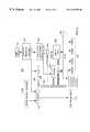
- FIG. 2shows an illumination stage 200 for a hardware rendering pipeline according to the invention.
- the stage 200includes three major units, namely gradient magnitude modulation 300 , reflectance mapping 800 , and lighting 1100 .
- the stage 200also includes four arithmetic logic units (ALUs), i.e., multipliers ( ⁇ circle around ( ⁇ ) ⁇ ) 201 - 204 , and a multiplexer (MUX) 210 .
- ALUsarithmetic logic units
- MUXmultiplexer
- Each input to the stage 200comprises an already classified sample 205 from the previous stage, its corresponding gradient vector (G UVW ) 104 , and an eye vector (E UVW ) 801 representing the direction from the sample point to the eye of the viewer.
- the sample and its associated gradient vectorare received at the rate of one pair per pipeline clock cycle.
- the eye vectoris constant throughout the volume. However, in the case of perspective projection, the eye vector must be adjusted for each ray.
- the illumination stage 200applies specular (s), diffuse (d) and emissive (e) lighting to the classified sample 205 using its associated gradient vector (G UVW ) 104 , and other controls described in detail below.
- the illumination stage 200in pipeline fashion, processes sample and vectors at the rate of one pair per pipeline clock cycle. That is, it comprises a fixed number of processing steps, and data flows through the stage in one direction from beginning to end. There are no loops, feedback, or variation in the number of steps of processing.
- Each of the sub-units of illumination stage 200is likewise organized in pipeline fashion to accept inputs at the rate of one per cycle and to product outputs at the same rate.
- the gradient vector 104is provided as input to the modulation unit 300 , and the reflectance map unit 800 , described below.
- the modulation unitgenerates four gradient magnitude modulation factors GMOM, GMIM e , GMIM d , and GMIM s .
- GMOMis the factor for opacity modulation, and the other three factors modulate color (RGB) intensities for emissive (e), diffuse (d), and specular (s) lighting, respectively. Modulation can be done in a number of different ways under user control.
- GMOMmodulates or attenuates ( 201 ) the alpha (opacity) component 206 of the classified sample 205 , supplied via the mux 210 .
- the mux 210also receives GuvW in the case that the illumination stage is bypassed altogether.
- GMIM eis multiplied in 202 by k e where k e represents the intensity of the emissive lighting, a constant for the entire volume.
- the modulated k eis denoted by Mk e .
- GMIM dis multiplied in 203 by I d to produce a modulated diffuse intensity MI d .
- GMIM sis multiplied in 204 by I s to produce a modulated specular lighting intensity MI s .
- the values I d and I sare provided via the reflectance mapping unit 800 .
- Mk e , MI d , and MI sare inputs to the Lighting unit 1100 , as described in FIG. 11 .
- the main output of the illumination stage 200is an illuminated sample 106 with Red, Green, Blue color components, and an Alpha component.
- the other two outputsare GmRangeValid 107 , and the sign 108 of the dot product of the gradient vector and the eye vector (G UVW ⁇ E UVW ).
- the value GmRangeValidis the result of comparing the computed gradient magnitude squared against a range defined in a range register. This signal can be used downstream in the compositing stage 140 of the pipeline 100 to further modify the resultant image by selectively including or excluding samples from being composited based upon their gradient magnitude.
- the sign of the dot productindicates whether the gradient is front-facing or back-facing.
- This signalcan also be used downstream in the compositing stage to identify a sample as being on a front-facing or back-facing surface. With this information, a simple segmentation of the volume data is possible.
- the outputis also clocked at the rate of one illuminated sample pipeline cycle.
- FIG. 3shows the gradient magnitude modulation unit 300 in greater detail.
- the purpose of the unitis to filter gradients using their magnitudes. Filtering accentuate surfaces, and removes noise.
- the unit 300includes an arithmetic logic unit 310 for taking the dot product of the gradient 104 with itself (G UVW ⁇ G UVW ), thereby obtaining the square of its magnitude
- the output of the squaring circuit 310is supplied to a comparator 320 along with range values from a GradientMagnitudeRange register 400 shown in FIG. 4 .
- the range valuesinclude a minimum and maximum valid magnitude.
- the outputis also truncated by circuit 330 , for example, a shift register, and then supplied to the multiplexer 340 along with
- the output of the mux 340is used to index a gradient magnitude look-up table (GMLUT) 380 , the entries of which are representations of fractional numbers in the range zero to one, inclusive.
- GMLUTgradient magnitude look-up table
- is also provided to a high pass filter (Hi-Pass) filter function 350 .
- Hi-Passhigh pass filter
- a signal selecting a particular modulation modeis provided on line 360 to a multiplexer 370 .
- This signalis derived from a gradient magnitude modulation register (GMM) 500 shown in FIG. 5 .
- the parameter values stored in the register 500 as bitscan be supplied by the user. Possible modes include various combinations of specular, diffuse, emissive, opacity, high pass diffuse, and high pass specular.
- the GMM 500includes fields 501 - 507 stored as 32 bits.
- the various bitscontrol exactly how the user desires to have the modulation performed.
- the grain, base, upper and lower range, and index source field 501 - 504are used in conjunction with the GMLUT 380 .
- the two high pass fields 505 - 506are used by the high pass function 350 .
- Field 505specifies a step value for a high pass filter function.
- Field 506eliminates either specular or diff-use lighting, or both.
- the values in field 507select a complex modulation mode for the mux 370 using the magnitude look-up table 380 .
- GMOM and GMIM ecan have either the GMLUT output or the value 1.0 applied to them based upon the setting of the modulateOpacity and modulateEmissive control bits 0 and 1 , in the notation of the C programming language:
- GMOMmodulateOpacity? GMLUT[
- GMIM emodulateEmissive? GMLUT[
- GMIM d and GMIM scan have any of the four following values:
- GMIM d(modulateDiffuse? GMLUT[
- GMIM s(modulateSpecular? GMLUT[
- the unit 300determines the modulation (attenuation) factors GMOM, GMIM e , GMIM d , and GMIM s 390 according to the selection signal on line 360 and the gradient magnitude of the classified sample 205 .
- the modulation factorscan be applied to lighting parameters (I d , I s , and k e ) and the opacity of the sample.
- ) of the gradient magnitudeis computed in unit 310 by taking the sum of the squares of the components of the gradient vector as follows:
- the gradient vector componentsare in the range of [ ⁇ 4095, . . . , +4095]. Given this range, the range of the computed square of the gradient magnitude is [0, . . . , 50,307,075].
- the GmRangeValid signal 107is set as follows:
- GmRangeValid(
- >GradientMagnitudeRange.Min) && (
- ⁇GradientMagnitudeRange.Max).
- the four modulation factors output by the modulation unit 300are GMOM, GMIM e , GMIM d , and GMIM s 390 . These outputs are in the range of [0.0, . . . 1.0]. As can be seen in FIG. 2 using multiplication logic, GMOM modulates the opacity (alpha) component of the sample, GMIM e modulates k e , and thus emissive lighting, GMIM d modulates I d , and thus diffuse lighting, and GMIM s modulates I s , and thus specular lighting.
- This modulationcan be used for a variety of reasons: minimize or eliminate lighting contributions of non-surfaces; minimize or eliminate lighting contributions of samples with low gradients that might exist due to errors in sampling and/or interpolation or noise errors inherent in the volume data set; apply light to only those samples with gradients in a specific range; and include or exclude samples from being composited (GMOM).
- the modulation factor GMOMcan, for instance, enable compositing of only homogenous regions by eliminating all surfaces or conversely, enable compositing of only surfaces.
- two modulation functionsare provided by the unit 300 , namely a complex function using a gradient magnitude look-up table (GMLUT) 380 , and the high pass filter function 350 .
- GMLUTgradient magnitude look-up table
- the high pass filter functionoperates on the approximated gradient magnitude.
- This step functionproduces a high pass modulation factor of either 0.0 or 1.0 to either side of a step value in the gradient magnitude range as defined by the hiPassStart field 505 of the GMM register 500 , shown in FIG. 5 .
- the following equationrepresents the step function:
- FIG. 6shows an example output 600 for this step function.
- the x-axisdepicts the lower-end of the input gradient's magnitude range [0, . . . , 255], and the y-axis the magnitude of the high pass output.
- the step value hiPassStartis set to 96.
- the outputis 0.0, otherwise, the output is 1.0.
- the GMLUT 380takes either
- the selection through multiplexer 340is controlled by the indexSource field 504 of the GMM register.
- the truncated magnitude squaredis used if the indexSource signal is true, and the magnitude
- the GMLUTis organized as 128 entries (entry0, . . . , entry127). Each entry is eight bits wide and stores a value in the range [0.0, . . . , 1.0].
- the look-upis controlled by the grain, base, upperRangeDefault and lowerRangeDefault fields 501 - 504 of the GMM register 500 . These fields allow the user to specify how the 128 table entries are spread across the table's 13-bit index range.
- the base field 502specifies where in the index range the first entry (entry0) of the table is indexed.
- the grain field 501specifies how far apart the table entries are spread starting at the base entry. In other words, the grain is the size of the incremental value between the entries. If the table is programmed to cover less than the 13-bit index range, then the upper-RangeDefault and lowerRangeDefault fields 503 - 504 specify the GMLUT output value for the uncovered regions above and below, either region can be zero or one.
- FIG. 7shows an example complex attenuation function 700 where the x-axis indicates the gradient index in the range of [0, . . . , 4k ⁇ 1], and the y-axis the GMLUT output value in the range [0.0, . . . , 1.0].
- the baseis 1536
- the grainis 2.
- Interpolationis performed between the two nearest table entries, and an 8-bit repeating fraction result is produced, again representing the range of [0.0, . . . , 1.0].
- the reflectance mapping unit 800includes a diffuse reflectance map 810 , and a specular reflectance map 820 .
- the unitalso includes a reflectance vector circuit 850 for deriving a reflection vector 802 from an eye vector (E UVW ) 801 and the gradient vector 104 (see also FIGS. 8 b and 10 ).
- a mux 840selectively chooses to index the specular reflectance map directly with either the gradient vector or the computed reflection vector 802 .
- the inputs to the unitsare the gradient and eye vectors 104 , 801 , and the outputs are the diffuse and specular intensities (I d , I s ) 803 - 804 .
- the reflectance mapping unit 800determines the specular and diffuse intensities (I s and I d ) for each sample 205 based upon its associated gradient vector 104 and the user-specified eye vector (E UVW ) 801 . As shown, the diff-use map 810 is indexed by the sample's gradient vector 104 , whereas the specular map 820 is typically indexed by either the gradient vector or the computed reflection vector 802 depending on a bypass (bypassRefVec) signal 901 shown in FIG. 9 .
- the maps and the indexing vectorsare all specified in unpermuted (U,V,W) object space but relative to “physical” or “lighting” space.
- the advantage of thisis that the reflectance maps do no have to be recalculated for different view directions. However, gradients estimated from anisotropic or non-orthogonal volume data sets must be corrected to “physical” space for the lighting calculations to work correctly.
- the specular map 820may be indexed directly by the gradient vector 104 , instead of by the reflection vector 802 , by setting a bit in a bypassRefVec field 901 in an EyeVector register 900 to true as shown in FIG. 9 .
- the other fields 902 - 904 of the register 900respectively store the (U, V, W) components of the eye vector.
- FIG. 10shows the relationship between the eye, reflection, and gradient vectors.
- the eye vector 801is defined to be the vector from the point on a “surface” of the volume 1000 to the eye 1001 . Its coordinates are specified in (U, V, W) object space by fields 902 - 904 . Note, this vector is normalized to a length of 1.
- the reflection from a light source 1002 to the eye 1001is dependent upon the gradient vector 104 .
- the reflectance vector circuit 850derives the reflection vector 802 based upon the eye vector 801 specified by the EyeVector register 900 and the gradient vector 104 .
- the gradient vectoris not of unit length, i.e., it is unnormalized.
- scaling unit 851scaling unit 851 , two dot product generators 852 , two multipliers 853 , and adder 854 .
- the circuit 850determines an unnormalized reflection vector Ru as:
- Guis the unnormalized gradient vector
- Ru and Eare the reflection and eye vectors
- ⁇is the “dot product” operator of two vectors. Note, only the direction, and not magnitude, is important for the reflection vector to index the reflectance map.
- each reflectance mapis organized as a table with, for example, 1536 entries.
- the entriesare spread across the six faces of an imaginary cube in 3D, that is 256 entries on each face.
- Each faceincludes four quadrants of 64 entries.
- the index to the mapsare the unnormalized gradient vector or the reflection vector as selected by the mux 840 . Again, magnitude is not important, but direction is.
- the outputsare values, interpolated from four entries of the map, based on the direction of the incoming vector.
- the selection of the face of the cube for accessis based on the maximum vector component, and its sign. For instance, if the vector is (75,0,0) in (u,v,w) space, then the right face of the cube (positive U) would be chosen. Whereas, if the vector is ( ⁇ 75,0,0), then the left face of the cube is chosen. The quadrant of a face is then selected based upon the sign of the other two vector components.
- a cluster of four neighboring table entriesis selected for interpolation to a resultant intensity value.
- This neighborhoodis selected by computing two weights that indicate the angle of deflection of the vector from the center of the cube's face to the outer edges of the face. Given that there are a power-of-two entries in each direction of a face's quadrant and the vector's components are represented by a power-of-two value, these weights can easily be derived by simple bit extraction of the vector's components.
- FIG. 11shows the lighting unit 1100 in greater detail.
- the unitcomprises a number of arithmetic logic units (ALUs) that add ( ⁇ circle around ( ⁇ ) ⁇ ) and multiply ( ⁇ circle around ( ⁇ ) ⁇ ) signals derived by the modulation and mapping units, and clamps.
- the lighting unit 1100applies the diffuse and specular lighting coefficients, k d and k s , the modulated emissive, diffuse, and specular intensities (Mk e , MI d , MI s ), and the specular color (R s , G s , B s ) 1101 to the classified RGBa sample 205 .
- ALUsarithmetic logic units
- Green[((MI d *k d )+Mk e )*Ga sample ]+[(MI s *k s )*G specular *a sample )]
- is derived from a square root approximation of
- the approximationis based on a Newton-Raphson approximation.
- Newton's methodinvolves numerous iterations to find the square-root of an input number. Recall from above the input is:
- this embodimentuses a one step version of the method.
- the Newton-Raphson methodis an iterative algorithm, based on tangents and their midpoints along a specified curve, in this case, the square root curve.
- the methodworks as follows:
- an intelligent guess (g) of the answeris derived based on the input number (n).
- Steps 2 through 4are repeated (iterated) until the error is within acceptable limits.
- FIG. 12graphically shows the Newton-Raphson method for an example number 163 .
- the x-axisindicates the input number
- the y-axisthe square root.
- the curve 1200plots the square root function.
- the input number (163is located between the two power-of-two numbers: 128 (2 7 and 256 (2 8 ).
- the computed square root of the lower bound (128)is chosen for the first guess. This is 11.3137.
- the division result, dividing the input number (163) by the guessed answer 11.3137yields 14.4073. This results in an error of 3.093 (14.4073-11.3137).
- the next guessis computed as follows:
- this methoduses both division and iteration. Division is extremely expensive in circuitry, and iteration inconsistent with a pipelined architecture. The multiplication by 1 ⁇ 2 can be accomplished by a simple shift right of the binary number. There are also a subtraction and possible complement, e.g., another adder, and an addition required for each iteration.
- the Synopsys companyoffers a square root circuit (DW 02 _sqrt: Combinatorial Square Root) in their DesignWare library based on Newton-Raphson, see “www.synopsys.com.” These are non-pipelined devices of which there are two variants with the following typical characteristics: either 300 ns and 9000 gates, or 600 ns and 1100 gates based on a cycle time of approximately 10 nanoseconds. These, of course, reuse the same divider, adder, and subtraction circuits for each of 30-60 iterations, precluding pipeline operation.
- DW 02 _sqrtCombinatorial Square Root
- a preferred implementationis based on Newton-Raphson's method but varies significantly in that it is pipelined.
- the present implementationemploys only one iteration and assumes predefined estimates of the square root at predefined points along the curve 1200 and tangents with pre-defined “slopes” connected, end-to-end, to approximate the square root function.
- predefined estimates of the square rootat predefined points along the curve 1200 and tangents with pre-defined “slopes” connected, end-to-end, to approximate the square root function.
- the inventiontakes advantage of the fact that the square root of a number expressed as a power-of-two (2 n ) is 2 n/2 . So, a first approximation is made by a simple range determination. For a given input find a nearest power-of-two number, and use its square root as the first guess. Now, if the range check is done for odd powers-of-two (i.e., in 2 n , n is odd), the first approximation will be in the middle of a range reducing the largest possible error by half.
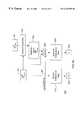
- FIG. 13is a block diagram of a preferred implementation of a square root approximation unit 1300 .
- the unitincludes a combinatorial logic block 1310 labeled “Select Range & Guess,” another block of combinatorial logic 1320 labeled “Divide Input by Guess,” an adder 1330 , and a shifter 1340 .
- the unit 1300takes a number (for example,
- the block 1310determines guess 1311 and shift 1312 .
- the value guessis the nearest square root, expressed as a power-of-two number, of a largest odd power-of-two number less than or equal to input.
- This range testcan be implemented as a simple bit test operation. The range test can begin at 32,768 (hex 0x8000 or 2 15 ) which has a nearest square root of 256 (2 8 ). In other words, because n is odd, the root is “guessed” as 2 (n+1)/2 . The corresponding initial guess is 256, and shift is 8.
- Block 1320divides input by guess. Because guess is a power-of-two, the divide can be done as simple shift (“>>”) operation.
- the adder 1330adds guess to the result of input/guess,
- the shifter 1340implements the final divide by two:
- the divideis simplified to a shift of the input. Then, according to the Newton-Raphson method, the guess is added to the result of dividing the input by the guess by the adder 1330 . The sum is then divided by two in the shifter 1340 to give a close approximation of the square root of the input.
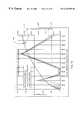
- FIG. 14is a graph 1400 comparing the exact gradient magnitude 1401 with the approximate gradient 1402 , and the error in the approximation 1403 .
- circuit 1300takes 850 gates and has a propagation delay of 5 nanoseconds, compared with 300 Ns and 9000 gates from above.
- the methodcan be improved to provide a better approximation without increasing the number of iterations, but rather by piecewise linear approximation of the square-root function that involves division by a fixed set of numbers that are not powers of two.
- the set of numbersis chosen so that division can still be accomplished by a small number of shifts and adds in a fixed number of steps.
- the divisionis accomplished with an adder and two shifts, which is much more effective than a full divider circuit.
- the effectis to decrease the size of the ranges for the first guess by doubling the number of points at which first “guess” is taken of the square root of the input. This reduces the maximum error shown in FIG. 14 in this modified single-step approximation of the square root.
- n/204 ⁇ (n/256+n/171)>>1(n/256+((n/256+n/128)>>1))>>1
- n/146 ⁇ (n/171+n/128)>>1(((n/256+n/128)>>1)+n/128)>>1
- the starting pointis selected from a range including the input number, and the sloped” tangent to be applied from that point to the next range.
- the choice of guessescan be predetermined to minimize the amount of error between the guess and the actual square root. Specifically, if the input value n lies between g i 2 and g i+1 2 , then the error in the approximation based on the these two guesses will be
- nbelow which g i is a better guess and above which g i+1 is a better guess is the value for which these two errors are equal—i.e., for which
Landscapes
- Engineering & Computer Science (AREA)
- Computer Graphics (AREA)
- Physics & Mathematics (AREA)
- General Physics & Mathematics (AREA)
- Theoretical Computer Science (AREA)
- Image Generation (AREA)
Abstract
Description
Claims (12)
Priority Applications (3)
| Application Number | Priority Date | Filing Date | Title |
|---|---|---|---|
| US09/315,661US6342885B1 (en) | 1998-11-12 | 1999-05-20 | Method and apparatus for illuminating volume data in a rendering pipeline |
| EP00109715AEP1054355A3 (en) | 1999-05-20 | 2000-05-08 | Method and apparatus for illuminating volume data in a rendering pipeline |
| JP2000148875AJP4420531B2 (en) | 1999-05-20 | 2000-05-19 | Irradiation apparatus and irradiation method for irradiating volume data in rendering pipeline |
Applications Claiming Priority (2)
| Application Number | Priority Date | Filing Date | Title |
|---|---|---|---|
| US09/190,643US6525449B1 (en) | 1997-12-04 | 1998-11-12 | Piezoelectric resonator utilizing a harmonic in a thickness-extensional vibration mode |
| US09/315,661US6342885B1 (en) | 1998-11-12 | 1999-05-20 | Method and apparatus for illuminating volume data in a rendering pipeline |
Related Parent Applications (1)
| Application Number | Title | Priority Date | Filing Date |
|---|---|---|---|
| US09/190,643Continuation-In-PartUS6525449B1 (en) | 1997-12-04 | 1998-11-12 | Piezoelectric resonator utilizing a harmonic in a thickness-extensional vibration mode |
Publications (1)
| Publication Number | Publication Date |
|---|---|
| US6342885B1true US6342885B1 (en) | 2002-01-29 |
Family
ID=23225489
Family Applications (1)
| Application Number | Title | Priority Date | Filing Date |
|---|---|---|---|
| US09/315,661Expired - LifetimeUS6342885B1 (en) | 1998-11-12 | 1999-05-20 | Method and apparatus for illuminating volume data in a rendering pipeline |
Country Status (3)
| Country | Link |
|---|---|
| US (1) | US6342885B1 (en) |
| EP (1) | EP1054355A3 (en) |
| JP (1) | JP4420531B2 (en) |
Cited By (40)
| Publication number | Priority date | Publication date | Assignee | Title |
|---|---|---|---|---|
| US20020053246A1 (en)* | 1998-08-05 | 2002-05-09 | Mannesmann Vdo Ag | Combination instrument |
| US6421057B1 (en)* | 1999-07-15 | 2002-07-16 | Terarecon, Inc. | Configurable volume rendering pipeline |
| US6424346B1 (en)* | 1999-07-15 | 2002-07-23 | Tera Recon, Inc. | Method and apparatus for mapping samples in a rendering pipeline |
| US6476810B1 (en)* | 1999-07-15 | 2002-11-05 | Terarecon, Inc. | Method and apparatus for generating a histogram of a volume data set |
| US20030043163A1 (en)* | 2001-08-21 | 2003-03-06 | Day Michael R. | Method for computing the intensity of specularly reflected light |
| US20030055896A1 (en)* | 2001-08-31 | 2003-03-20 | Hui Hu | On-line image processing and communication system |
| US20030086595A1 (en)* | 2001-11-07 | 2003-05-08 | Hui Hu | Display parameter-dependent pre-transmission processing of image data |
| US20030108251A1 (en)* | 2001-12-11 | 2003-06-12 | Samsung Electronics Co., Ltd. | Apparatus generating 3-dimensional image from 2-dimensional image and method thereof |
| US6614431B1 (en) | 2001-01-18 | 2003-09-02 | David J. Collodi | Method and system for improved per-pixel shading in a computer graphics system |
| US6624812B1 (en) | 1997-06-27 | 2003-09-23 | David J. Collodi | Method and apparatus for providing shading in a graphic display system |
| US6654013B1 (en)* | 2000-03-17 | 2003-11-25 | Hewlett-Packard Development Company, Lp. | Apparatus for and method of enhancing shape perception with parametric texture maps |
| US20050090312A1 (en)* | 2003-10-22 | 2005-04-28 | Scott Campbell | System and method for recording and displaying a graphical path in a video game |
| US20050143654A1 (en)* | 2003-11-29 | 2005-06-30 | Karel Zuiderveld | Systems and methods for segmented volume rendering using a programmable graphics pipeline |
| US20060001674A1 (en)* | 2001-10-10 | 2006-01-05 | Sony Computer Entertainment America Inc. | Environment mapping |
| US7071937B1 (en)* | 2000-05-30 | 2006-07-04 | Ccvg, Inc. | Dirt map method and apparatus for graphic display system |
| US20060227137A1 (en)* | 2005-03-29 | 2006-10-12 | Tim Weyrich | Skin reflectance model for representing and rendering faces |
| US20070014486A1 (en)* | 2005-07-13 | 2007-01-18 | Thomas Schiwietz | High speed image reconstruction for k-space trajectory data using graphic processing unit (GPU) |
| US20080231632A1 (en)* | 2007-03-21 | 2008-09-25 | Varian Medical Systems Technologies, Inc. | Accelerated volume image rendering pipeline method and apparatus |
| US20110181776A1 (en)* | 2005-06-22 | 2011-07-28 | Dominic Saul Mallinson | Delay matching in audio/video systems |
| US20110205240A1 (en)* | 2006-05-04 | 2011-08-25 | Richard Marks | Implementing Lighting Control of a User Environment |
| USRE42952E1 (en) | 1999-11-05 | 2011-11-22 | Vital Images, Inc. | Teleradiology systems for rendering and visualizing remotely-located volume data sets |
| US8204272B2 (en) | 2006-05-04 | 2012-06-19 | Sony Computer Entertainment Inc. | Lighting control of a user environment via a display device |
| US8289325B2 (en) | 2004-10-06 | 2012-10-16 | Sony Computer Entertainment America Llc | Multi-pass shading |
| US9342817B2 (en) | 2011-07-07 | 2016-05-17 | Sony Interactive Entertainment LLC | Auto-creating groups for sharing photos |
| US9371489B2 (en) | 2013-03-15 | 2016-06-21 | GreenStract, LLC | Plant-based compositions and uses thereof |
| US20160239998A1 (en)* | 2015-02-16 | 2016-08-18 | Thomson Licensing | Device and method for estimating a glossy part of radiation |
| US9495604B1 (en) | 2013-01-09 | 2016-11-15 | D.R. Systems, Inc. | Intelligent management of computerized advanced processing |
| US9526692B2 (en) | 2013-03-15 | 2016-12-27 | GreenStract, LLC | Plant-based compositions and uses thereof |
| US9672477B1 (en) | 2006-11-22 | 2017-06-06 | D.R. Systems, Inc. | Exam scheduling with customer configured notifications |
| US9684762B2 (en) | 2009-09-28 | 2017-06-20 | D.R. Systems, Inc. | Rules-based approach to rendering medical imaging data |
| US9727938B1 (en) | 2004-11-04 | 2017-08-08 | D.R. Systems, Inc. | Systems and methods for retrieval of medical data |
| US9734576B2 (en) | 2004-11-04 | 2017-08-15 | D.R. Systems, Inc. | Systems and methods for interleaving series of medical images |
| US9836202B1 (en) | 2004-11-04 | 2017-12-05 | D.R. Systems, Inc. | Systems and methods for viewing medical images |
| US10540763B2 (en) | 2004-11-04 | 2020-01-21 | Merge Healthcare Solutions Inc. | Systems and methods for matching, naming, and displaying medical images |
| US10579903B1 (en) | 2011-08-11 | 2020-03-03 | Merge Healthcare Solutions Inc. | Dynamic montage reconstruction |
| US10592688B2 (en) | 2008-11-19 | 2020-03-17 | Merge Healthcare Solutions Inc. | System and method of providing dynamic and customizable medical examination forms |
| US10614615B2 (en) | 2004-11-04 | 2020-04-07 | Merge Healthcare Solutions Inc. | Systems and methods for viewing medical 3D imaging volumes |
| US10786736B2 (en) | 2010-05-11 | 2020-09-29 | Sony Interactive Entertainment LLC | Placement of user information in a game space |
| US10909168B2 (en) | 2015-04-30 | 2021-02-02 | Merge Healthcare Solutions Inc. | Database systems and interactive user interfaces for dynamic interaction with, and review of, digital medical image data |
| CN116472440A (en)* | 2020-10-27 | 2023-07-21 | 杰富意钢铁株式会社 | Surface temperature measurement method, surface temperature measurement device, method for producing hot-dip galvanized steel sheet, and apparatus for producing hot-dip galvanized steel sheet |
Citations (11)
| Publication number | Priority date | Publication date | Assignee | Title |
|---|---|---|---|---|
| US5201035A (en) | 1990-07-09 | 1993-04-06 | The United States Of America As Represented By The Secretary Of The Air Force | Dynamic algorithm selection for volume rendering, isocontour and body extraction within a multiple-instruction, multiple-data multiprocessor |
| US5381518A (en) | 1986-04-14 | 1995-01-10 | Pixar | Method and apparatus for imaging volume data using voxel values |
| US5467459A (en) | 1991-08-13 | 1995-11-14 | Board Of Regents Of The University Of Washington | Imaging and graphics processing system |
| US5594842A (en) | 1994-09-06 | 1997-01-14 | The Research Foundation Of State University Of New York | Apparatus and method for real-time volume visualization |
| US5644689A (en) | 1992-01-13 | 1997-07-01 | Hitachi, Ltd. | Arbitrary viewpoint three-dimensional imaging method using compressed voxel data constructed by a directed search of voxel data representing an image of an object and an arbitrary viewpoint |
| US5734384A (en)* | 1991-11-29 | 1998-03-31 | Picker International, Inc. | Cross-referenced sectioning and reprojection of diagnostic image volumes |
| US5751928A (en)* | 1992-08-26 | 1998-05-12 | Bakalash; Reuven | Parallel computing system for volumetric modeling, data processing and visualization volumetric |
| US5756354A (en)* | 1992-06-24 | 1998-05-26 | B.V.R. Technologies Ltd. | Animating three dimensional images by selectively processing intermediate animation frames |
| US5760781A (en)* | 1994-09-06 | 1998-06-02 | The Research Foundation Of State University Of New York | Apparatus and method for real-time volume visualization |
| US5781194A (en)* | 1996-08-29 | 1998-07-14 | Animatek International, Inc. | Real-time projection of voxel-based object |
| US5831623A (en)* | 1995-08-09 | 1998-11-03 | Mitsubishi Denki Kabushiki Kaisha | Volume rendering apparatus and method |
Family Cites Families (1)
| Publication number | Priority date | Publication date | Assignee | Title |
|---|---|---|---|---|
| JP2651787B2 (en)* | 1993-09-03 | 1997-09-10 | 日本アイ・ビー・エム株式会社 | Interactive volume rendering method and apparatus |
- 1999
- 1999-05-20USUS09/315,661patent/US6342885B1/ennot_activeExpired - Lifetime
- 2000
- 2000-05-08EPEP00109715Apatent/EP1054355A3/ennot_activeWithdrawn
- 2000-05-19JPJP2000148875Apatent/JP4420531B2/ennot_activeExpired - Fee Related
Patent Citations (11)
| Publication number | Priority date | Publication date | Assignee | Title |
|---|---|---|---|---|
| US5381518A (en) | 1986-04-14 | 1995-01-10 | Pixar | Method and apparatus for imaging volume data using voxel values |
| US5201035A (en) | 1990-07-09 | 1993-04-06 | The United States Of America As Represented By The Secretary Of The Air Force | Dynamic algorithm selection for volume rendering, isocontour and body extraction within a multiple-instruction, multiple-data multiprocessor |
| US5467459A (en) | 1991-08-13 | 1995-11-14 | Board Of Regents Of The University Of Washington | Imaging and graphics processing system |
| US5734384A (en)* | 1991-11-29 | 1998-03-31 | Picker International, Inc. | Cross-referenced sectioning and reprojection of diagnostic image volumes |
| US5644689A (en) | 1992-01-13 | 1997-07-01 | Hitachi, Ltd. | Arbitrary viewpoint three-dimensional imaging method using compressed voxel data constructed by a directed search of voxel data representing an image of an object and an arbitrary viewpoint |
| US5756354A (en)* | 1992-06-24 | 1998-05-26 | B.V.R. Technologies Ltd. | Animating three dimensional images by selectively processing intermediate animation frames |
| US5751928A (en)* | 1992-08-26 | 1998-05-12 | Bakalash; Reuven | Parallel computing system for volumetric modeling, data processing and visualization volumetric |
| US5594842A (en) | 1994-09-06 | 1997-01-14 | The Research Foundation Of State University Of New York | Apparatus and method for real-time volume visualization |
| US5760781A (en)* | 1994-09-06 | 1998-06-02 | The Research Foundation Of State University Of New York | Apparatus and method for real-time volume visualization |
| US5831623A (en)* | 1995-08-09 | 1998-11-03 | Mitsubishi Denki Kabushiki Kaisha | Volume rendering apparatus and method |
| US5781194A (en)* | 1996-08-29 | 1998-07-14 | Animatek International, Inc. | Real-time projection of voxel-based object |
Non-Patent Citations (4)
| Title |
|---|
| A. Mammen; "Transparency and Antialiasing Algorithms Implemented with the Virtual Pixel Maps Technique"; IEEE Computer Graphics & Applications, Jul., 1989; pp. 43-55. |
| D. Voorhies et al.; "Virtual Graphics"; Computer Graphics, vol. 22 No. 4, Aug., 1988; pp. 247-253. |
| J. Lichtermann; "Design of a Fast Voxel Processor for Parallel Volume Visualization"; pp. 83-92. |
| R. Drebin et al.; "Volume Rendering"; Computer Graphics, vol. 22 No. 4, Aug., 1988; pp. 65-74. |
Cited By (75)
| Publication number | Priority date | Publication date | Assignee | Title |
|---|---|---|---|---|
| US6624812B1 (en) | 1997-06-27 | 2003-09-23 | David J. Collodi | Method and apparatus for providing shading in a graphic display system |
| US20050168466A1 (en)* | 1997-06-27 | 2005-08-04 | Collodi David J. | Method and apparatus for providing shading in a graphic display system |
| US6833830B2 (en) | 1997-06-27 | 2004-12-21 | David J. Collodi | Method and apparatus for providing shading in a graphic display system |
| US20040056860A1 (en)* | 1997-06-27 | 2004-03-25 | Collodi David J. | Method and apparatus for providing shading in a graphic display system |
| US20020053246A1 (en)* | 1998-08-05 | 2002-05-09 | Mannesmann Vdo Ag | Combination instrument |
| US6421057B1 (en)* | 1999-07-15 | 2002-07-16 | Terarecon, Inc. | Configurable volume rendering pipeline |
| US6424346B1 (en)* | 1999-07-15 | 2002-07-23 | Tera Recon, Inc. | Method and apparatus for mapping samples in a rendering pipeline |
| US6476810B1 (en)* | 1999-07-15 | 2002-11-05 | Terarecon, Inc. | Method and apparatus for generating a histogram of a volume data set |
| USRE42952E1 (en) | 1999-11-05 | 2011-11-22 | Vital Images, Inc. | Teleradiology systems for rendering and visualizing remotely-located volume data sets |
| USRE44336E1 (en) | 1999-11-05 | 2013-07-02 | Vital Images, Inc. | Teleradiology systems for rendering and visualizing remotely-located volume data sets |
| US6654013B1 (en)* | 2000-03-17 | 2003-11-25 | Hewlett-Packard Development Company, Lp. | Apparatus for and method of enhancing shape perception with parametric texture maps |
| US7071937B1 (en)* | 2000-05-30 | 2006-07-04 | Ccvg, Inc. | Dirt map method and apparatus for graphic display system |
| US20040113911A1 (en)* | 2001-01-18 | 2004-06-17 | Collodi David J. | Method and system for improved per-pixel shading in a computer graphics system |
| US6614431B1 (en) | 2001-01-18 | 2003-09-02 | David J. Collodi | Method and system for improved per-pixel shading in a computer graphics system |
| US20030043163A1 (en)* | 2001-08-21 | 2003-03-06 | Day Michael R. | Method for computing the intensity of specularly reflected light |
| US6781594B2 (en)* | 2001-08-21 | 2004-08-24 | Sony Computer Entertainment America Inc. | Method for computing the intensity of specularly reflected light |
| US20050001836A1 (en)* | 2001-08-21 | 2005-01-06 | Day Michael R. | Method for computing the intensity of specularly reflected light |
| US20060214943A1 (en)* | 2001-08-21 | 2006-09-28 | Sony Computer Entertainment America Inc. | Computing the intensity of specularly reflected light |
| US7079138B2 (en) | 2001-08-21 | 2006-07-18 | Sony Computer Entertainment America Inc. | Method for computing the intensity of specularly reflected light |
| US20030055896A1 (en)* | 2001-08-31 | 2003-03-20 | Hui Hu | On-line image processing and communication system |
| US7039723B2 (en) | 2001-08-31 | 2006-05-02 | Hinnovation, Inc. | On-line image processing and communication system |
| US20060001674A1 (en)* | 2001-10-10 | 2006-01-05 | Sony Computer Entertainment America Inc. | Environment mapping |
| US7786993B2 (en) | 2001-10-10 | 2010-08-31 | Sony Computer Entertainment America Llc | Environment mapping |
| US20030086595A1 (en)* | 2001-11-07 | 2003-05-08 | Hui Hu | Display parameter-dependent pre-transmission processing of image data |
| US7319798B2 (en)* | 2001-12-11 | 2008-01-15 | Samsung Electronics Co., Ltd. | Apparatus generating 3-dimensional image from 2-dimensional image and method thereof |
| US20030108251A1 (en)* | 2001-12-11 | 2003-06-12 | Samsung Electronics Co., Ltd. | Apparatus generating 3-dimensional image from 2-dimensional image and method thereof |
| US8133115B2 (en) | 2003-10-22 | 2012-03-13 | Sony Computer Entertainment America Llc | System and method for recording and displaying a graphical path in a video game |
| US20050090312A1 (en)* | 2003-10-22 | 2005-04-28 | Scott Campbell | System and method for recording and displaying a graphical path in a video game |
| US20050143654A1 (en)* | 2003-11-29 | 2005-06-30 | Karel Zuiderveld | Systems and methods for segmented volume rendering using a programmable graphics pipeline |
| US8289325B2 (en) | 2004-10-06 | 2012-10-16 | Sony Computer Entertainment America Llc | Multi-pass shading |
| US10614615B2 (en) | 2004-11-04 | 2020-04-07 | Merge Healthcare Solutions Inc. | Systems and methods for viewing medical 3D imaging volumes |
| US10437444B2 (en) | 2004-11-04 | 2019-10-08 | Merge Healthcare Soltuions Inc. | Systems and methods for viewing medical images |
| US10790057B2 (en) | 2004-11-04 | 2020-09-29 | Merge Healthcare Solutions Inc. | Systems and methods for retrieval of medical data |
| US9727938B1 (en) | 2004-11-04 | 2017-08-08 | D.R. Systems, Inc. | Systems and methods for retrieval of medical data |
| US9734576B2 (en) | 2004-11-04 | 2017-08-15 | D.R. Systems, Inc. | Systems and methods for interleaving series of medical images |
| US11177035B2 (en) | 2004-11-04 | 2021-11-16 | International Business Machines Corporation | Systems and methods for matching, naming, and displaying medical images |
| US9836202B1 (en) | 2004-11-04 | 2017-12-05 | D.R. Systems, Inc. | Systems and methods for viewing medical images |
| US10096111B2 (en) | 2004-11-04 | 2018-10-09 | D.R. Systems, Inc. | Systems and methods for interleaving series of medical images |
| US10540763B2 (en) | 2004-11-04 | 2020-01-21 | Merge Healthcare Solutions Inc. | Systems and methods for matching, naming, and displaying medical images |
| US7319467B2 (en)* | 2005-03-29 | 2008-01-15 | Mitsubishi Electric Research Laboratories, Inc. | Skin reflectance model for representing and rendering faces |
| US20060227137A1 (en)* | 2005-03-29 | 2006-10-12 | Tim Weyrich | Skin reflectance model for representing and rendering faces |
| US8284310B2 (en) | 2005-06-22 | 2012-10-09 | Sony Computer Entertainment America Llc | Delay matching in audio/video systems |
| US20110181776A1 (en)* | 2005-06-22 | 2011-07-28 | Dominic Saul Mallinson | Delay matching in audio/video systems |
| US20070014486A1 (en)* | 2005-07-13 | 2007-01-18 | Thomas Schiwietz | High speed image reconstruction for k-space trajectory data using graphic processing unit (GPU) |
| US7916144B2 (en)* | 2005-07-13 | 2011-03-29 | Siemens Medical Solutions Usa, Inc. | High speed image reconstruction for k-space trajectory data using graphic processing unit (GPU) |
| US8204272B2 (en) | 2006-05-04 | 2012-06-19 | Sony Computer Entertainment Inc. | Lighting control of a user environment via a display device |
| US8243089B2 (en) | 2006-05-04 | 2012-08-14 | Sony Computer Entertainment Inc. | Implementing lighting control of a user environment |
| US20110205240A1 (en)* | 2006-05-04 | 2011-08-25 | Richard Marks | Implementing Lighting Control of a User Environment |
| US9672477B1 (en) | 2006-11-22 | 2017-06-06 | D.R. Systems, Inc. | Exam scheduling with customer configured notifications |
| US10896745B2 (en) | 2006-11-22 | 2021-01-19 | Merge Healthcare Solutions Inc. | Smart placement rules |
| US9754074B1 (en) | 2006-11-22 | 2017-09-05 | D.R. Systems, Inc. | Smart placement rules |
| US20080231632A1 (en)* | 2007-03-21 | 2008-09-25 | Varian Medical Systems Technologies, Inc. | Accelerated volume image rendering pipeline method and apparatus |
| US10592688B2 (en) | 2008-11-19 | 2020-03-17 | Merge Healthcare Solutions Inc. | System and method of providing dynamic and customizable medical examination forms |
| US9934568B2 (en) | 2009-09-28 | 2018-04-03 | D.R. Systems, Inc. | Computer-aided analysis and rendering of medical images using user-defined rules |
| US9684762B2 (en) | 2009-09-28 | 2017-06-20 | D.R. Systems, Inc. | Rules-based approach to rendering medical imaging data |
| US9892341B2 (en) | 2009-09-28 | 2018-02-13 | D.R. Systems, Inc. | Rendering of medical images using user-defined rules |
| US10607341B2 (en) | 2009-09-28 | 2020-03-31 | Merge Healthcare Solutions Inc. | Rules-based processing and presentation of medical images based on image plane |
| US11478706B2 (en) | 2010-05-11 | 2022-10-25 | Sony Interactive Entertainment LLC | Placement of user information in a game space |
| US10786736B2 (en) | 2010-05-11 | 2020-09-29 | Sony Interactive Entertainment LLC | Placement of user information in a game space |
| US9342817B2 (en) | 2011-07-07 | 2016-05-17 | Sony Interactive Entertainment LLC | Auto-creating groups for sharing photos |
| US10579903B1 (en) | 2011-08-11 | 2020-03-03 | Merge Healthcare Solutions Inc. | Dynamic montage reconstruction |
| US10672512B2 (en) | 2013-01-09 | 2020-06-02 | Merge Healthcare Solutions Inc. | Intelligent management of computerized advanced processing |
| US11094416B2 (en) | 2013-01-09 | 2021-08-17 | International Business Machines Corporation | Intelligent management of computerized advanced processing |
| US9495604B1 (en) | 2013-01-09 | 2016-11-15 | D.R. Systems, Inc. | Intelligent management of computerized advanced processing |
| US10665342B2 (en) | 2013-01-09 | 2020-05-26 | Merge Healthcare Solutions Inc. | Intelligent management of computerized advanced processing |
| US9526692B2 (en) | 2013-03-15 | 2016-12-27 | GreenStract, LLC | Plant-based compositions and uses thereof |
| US9624437B2 (en) | 2013-03-15 | 2017-04-18 | GreenStract, LLC | Plant-based compositions and uses thereof |
| US9371489B2 (en) | 2013-03-15 | 2016-06-21 | GreenStract, LLC | Plant-based compositions and uses thereof |
| US10136652B2 (en) | 2013-03-15 | 2018-11-27 | GreenStract, LLC | Plant-based compositions and uses thereof |
| US9388343B2 (en) | 2013-03-15 | 2016-07-12 | GreenStract, LLC | Plant-based compositions and uses thereof |
| US20160239998A1 (en)* | 2015-02-16 | 2016-08-18 | Thomson Licensing | Device and method for estimating a glossy part of radiation |
| US10607404B2 (en)* | 2015-02-16 | 2020-03-31 | Thomson Licensing | Device and method for estimating a glossy part of radiation |
| US10909168B2 (en) | 2015-04-30 | 2021-02-02 | Merge Healthcare Solutions Inc. | Database systems and interactive user interfaces for dynamic interaction with, and review of, digital medical image data |
| US10929508B2 (en) | 2015-04-30 | 2021-02-23 | Merge Healthcare Solutions Inc. | Database systems and interactive user interfaces for dynamic interaction with, and indications of, digital medical image data |
| CN116472440A (en)* | 2020-10-27 | 2023-07-21 | 杰富意钢铁株式会社 | Surface temperature measurement method, surface temperature measurement device, method for producing hot-dip galvanized steel sheet, and apparatus for producing hot-dip galvanized steel sheet |
Also Published As
| Publication number | Publication date |
|---|---|
| JP2000357241A (en) | 2000-12-26 |
| EP1054355A3 (en) | 2002-10-23 |
| JP4420531B2 (en) | 2010-02-24 |
| EP1054355A2 (en) | 2000-11-22 |
Similar Documents
| Publication | Publication Date | Title |
|---|---|---|
| US6342885B1 (en) | Method and apparatus for illuminating volume data in a rendering pipeline | |
| US6356265B1 (en) | Method and apparatus for modulating lighting with gradient magnitudes of volume data in a rendering pipeline | |
| US6426749B1 (en) | Method and apparatus for mapping reflectance while illuminating volume data in a rendering pipeline | |
| US6369816B1 (en) | Method for modulating volume samples using gradient magnitudes and complex functions over a range of values | |
| US6404429B1 (en) | Method for modulating volume samples with gradient magnitude vectors and step functions | |
| US6411296B1 (en) | Method and apparatus for applying modulated lighting to volume data in a rendering pipeline | |
| US6333744B1 (en) | Graphics pipeline including combiner stages | |
| US7362328B2 (en) | Interface and method of interfacing between a parametric modelling unit and a polygon based rendering system | |
| US6421057B1 (en) | Configurable volume rendering pipeline | |
| US6483507B2 (en) | Super-sampling and gradient estimation in a ray-casting volume rendering system | |
| EP1001379A2 (en) | Incrementally calculated cut-plane region for viewing a portion of a volume data set in real-time | |
| EP1183653A1 (en) | A method for forming a perspective rendering from a voxel space | |
| van Scheltinga et al. | Design of an on-chip reflectance map | |
| EP1054358A2 (en) | Method and apparatus for approximating a function | |
| US6191788B1 (en) | Method and apparatus for approximating nonlinear functions in a graphics system | |
| EP1069532A2 (en) | Multi-pass volume rendering pipeline | |
| Rossl et al. | Visualization of volume data with quadratic super splines | |
| US9514566B2 (en) | Image-generated system using beta distribution to provide accurate shadow mapping | |
| Matsumura et al. | Accelerated isosurface polygonization for dynamic volume data using programmable graphics hardware | |
| Bitter et al. | Squeeze: numerical-precision-optimized volume rendering | |
| Feda et al. | A median cut algorithm for efficient sampling of radiosity functions | |
| Knittel | A compact shader for FPGA-based volume rendering accelerators | |
| Bertilsson et al. | Real-Time Global Illumination in Web-Browsers | |
| Morén | Efficient volume rendering on the face centered and body centered cubic grids | |
| Parilov et al. | Per-pixel divisions |
Legal Events
| Date | Code | Title | Description |
|---|---|---|---|
| AS | Assignment | Owner name:MITSUBISHI ELECTRIC INFORMANTION TECHNOLOGY CENTER Free format text:ASSIGNMENT OF ASSIGNORS INTEREST;ASSIGNORS:KNITTEL, JAMES M.;HARDENBERGH, JAN C.;PFISTER, HANSPETER;AND OTHERS;REEL/FRAME:009983/0927;SIGNING DATES FROM 19990502 TO 19990512 | |
| AS | Assignment | Owner name:MITSUBISHI ELECTIC INFORMATION TECHNOLOGY CENTER A Free format text:ASSIGNMENT OF ASSIGNORS INTEREST;ASSIGNOR:MARTIN, DREW R.;REEL/FRAME:010053/0680 Effective date:19990526 | |
| AS | Assignment | Owner name:TERARECON, INC., CALIFORNIA Free format text:ASSIGNMENT OF ASSIGNORS INTEREST;ASSIGNOR:MITSUBISHI ELECTRIC RESEARCH LABORATORIES, INC. FORMERLY KNOWN AS MITSUBISHI ELECTRIC INFORMATION TECHNOLOGY CENTER AMERICA, INC.;REEL/FRAME:011575/0674 Effective date:20010202 | |
| STCF | Information on status: patent grant | Free format text:PATENTED CASE | |
| CC | Certificate of correction | ||
| FEPP | Fee payment procedure | Free format text:PAYOR NUMBER ASSIGNED (ORIGINAL EVENT CODE: ASPN); ENTITY STATUS OF PATENT OWNER: LARGE ENTITY | |
| FPAY | Fee payment | Year of fee payment:4 | |
| FPAY | Fee payment | Year of fee payment:8 | |
| FPAY | Fee payment | Year of fee payment:12 | |
| AS | Assignment | Owner name:OXFORD FINANCE LLC, VIRGINIA Free format text:SECURITY INTEREST;ASSIGNOR:TERARCON, INC.;REEL/FRAME:052115/0187 Effective date:20200302 |