US6342055B1 - Bone fixation system - Google Patents
Bone fixation systemDownload PDFInfo
- Publication number
- US6342055B1 US6342055B1US09/322,545US32254599AUS6342055B1US 6342055 B1US6342055 B1US 6342055B1US 32254599 AUS32254599 AUS 32254599AUS 6342055 B1US6342055 B1US 6342055B1
- Authority
- US
- United States
- Prior art keywords
- bone
- fastener
- fastener receiving
- head portion
- bone fixation
- Prior art date
- Legal status (The legal status is an assumption and is not a legal conclusion. Google has not performed a legal analysis and makes no representation as to the accuracy of the status listed.)
- Expired - Lifetime
Links
- 210000000988bone and boneAnatomy0.000titleclaimsabstractdescription164
- 230000004927fusionEffects0.000claimsabstractdescription36
- 230000007935neutral effectEffects0.000claimsdescription8
- 230000000717retained effectEffects0.000claimsdescription7
- 230000002792vascularEffects0.000claimsdescription6
- 230000013011matingEffects0.000claimsdescription4
- 238000003780insertionMethods0.000claimsdescription3
- 230000037431insertionEffects0.000claimsdescription3
- 239000002131composite materialSubstances0.000description9
- 230000035876healingEffects0.000description7
- 239000000463materialSubstances0.000description7
- 230000002980postoperative effectEffects0.000description6
- 238000003384imaging methodMethods0.000description5
- 238000002595magnetic resonance imagingMethods0.000description4
- 239000004696Poly ether ether ketoneSubstances0.000description3
- 208000020339Spinal injuryDiseases0.000description3
- 229910001069Ti alloyInorganic materials0.000description3
- RTAQQCXQSZGOHL-UHFFFAOYSA-NTitaniumChemical compound[Ti]RTAQQCXQSZGOHL-UHFFFAOYSA-N0.000description3
- 238000005452bendingMethods0.000description3
- 239000007943implantSubstances0.000description3
- VNWKTOKETHGBQD-UHFFFAOYSA-NmethaneChemical compoundCVNWKTOKETHGBQD-UHFFFAOYSA-N0.000description3
- 238000000034methodMethods0.000description3
- 238000012986modificationMethods0.000description3
- 230000004048modificationEffects0.000description3
- 229920002530polyetherether ketonePolymers0.000description3
- 239000011347resinSubstances0.000description3
- 229920005989resinPolymers0.000description3
- 229910052719titaniumInorganic materials0.000description3
- 239000010936titaniumSubstances0.000description3
- 238000011282treatmentMethods0.000description3
- 229920000049Carbon (fiber)Polymers0.000description2
- 206010061363Skeletal injuryDiseases0.000description2
- 208000027418Wounds and injuryDiseases0.000description2
- 230000008901benefitEffects0.000description2
- 239000004917carbon fiberSubstances0.000description2
- 230000006378damageEffects0.000description2
- 230000007423decreaseEffects0.000description2
- 239000003102growth factorSubstances0.000description2
- 208000014674injuryDiseases0.000description2
- 229920000642polymerPolymers0.000description2
- 239000010935stainless steelSubstances0.000description2
- 229910001220stainless steelInorganic materials0.000description2
- 210000001519tissueAnatomy0.000description2
- 208000020307Spinal diseaseDiseases0.000description1
- 238000013459approachMethods0.000description1
- JUPQTSLXMOCDHR-UHFFFAOYSA-Nbenzene-1,4-diol;bis(4-fluorophenyl)methanoneChemical compoundOC1=CC=C(O)C=C1.C1=CC(F)=CC=C1C(=O)C1=CC=C(F)C=C1JUPQTSLXMOCDHR-UHFFFAOYSA-N0.000description1
- 230000008933bodily movementEffects0.000description1
- 230000008468bone growthEffects0.000description1
- 239000004918carbon fiber reinforced polymerSubstances0.000description1
- 230000008859changeEffects0.000description1
- 230000007812deficiencyEffects0.000description1
- 230000001419dependent effectEffects0.000description1
- 238000010438heat treatmentMethods0.000description1
- 238000001746injection mouldingMethods0.000description1
- 238000009434installationMethods0.000description1
- 238000011900installation processMethods0.000description1
- 230000001788irregularEffects0.000description1
- 230000033001locomotionEffects0.000description1
- 230000001045lordotic effectEffects0.000description1
- 238000003754machiningMethods0.000description1
- 239000003550markerSubstances0.000description1
- 238000012856packingMethods0.000description1
- 229920006260polyaryletherketonePolymers0.000description1
- 239000002861polymer materialSubstances0.000description1
- 239000002994raw materialSubstances0.000description1
- 238000007788rougheningMethods0.000description1
- 238000001356surgical procedureMethods0.000description1
- 229920001169thermoplasticPolymers0.000description1
- 239000004416thermosoftening plasticSubstances0.000description1
- 230000008467tissue growthEffects0.000description1
- 238000012546transferMethods0.000description1
- 230000007704transitionEffects0.000description1
Images


Classifications
- A—HUMAN NECESSITIES
- A61—MEDICAL OR VETERINARY SCIENCE; HYGIENE
- A61B—DIAGNOSIS; SURGERY; IDENTIFICATION
- A61B17/00—Surgical instruments, devices or methods
- A61B17/56—Surgical instruments or methods for treatment of bones or joints; Devices specially adapted therefor
- A61B17/58—Surgical instruments or methods for treatment of bones or joints; Devices specially adapted therefor for osteosynthesis, e.g. bone plates, screws or setting implements
- A61B17/68—Internal fixation devices, including fasteners and spinal fixators, even if a part thereof projects from the skin
- A61B17/70—Spinal positioners or stabilisers, e.g. stabilisers comprising fluid filler in an implant
- A61B17/7059—Cortical plates
- A—HUMAN NECESSITIES
- A61—MEDICAL OR VETERINARY SCIENCE; HYGIENE
- A61B—DIAGNOSIS; SURGERY; IDENTIFICATION
- A61B17/00—Surgical instruments, devices or methods
- A61B17/56—Surgical instruments or methods for treatment of bones or joints; Devices specially adapted therefor
- A61B17/58—Surgical instruments or methods for treatment of bones or joints; Devices specially adapted therefor for osteosynthesis, e.g. bone plates, screws or setting implements
- A61B17/68—Internal fixation devices, including fasteners and spinal fixators, even if a part thereof projects from the skin
- A61B17/84—Fasteners therefor or fasteners being internal fixation devices
- A61B17/86—Pins or screws or threaded wires; nuts therefor
- A61B17/8625—Shanks, i.e. parts contacting bone tissue
- A61B17/863—Shanks, i.e. parts contacting bone tissue with thread interrupted or changing its form along shank, other than constant taper
- A—HUMAN NECESSITIES
- A61—MEDICAL OR VETERINARY SCIENCE; HYGIENE
- A61B—DIAGNOSIS; SURGERY; IDENTIFICATION
- A61B17/00—Surgical instruments, devices or methods
- A61B17/56—Surgical instruments or methods for treatment of bones or joints; Devices specially adapted therefor
- A61B17/58—Surgical instruments or methods for treatment of bones or joints; Devices specially adapted therefor for osteosynthesis, e.g. bone plates, screws or setting implements
- A61B17/88—Osteosynthesis instruments; Methods or means for implanting or extracting internal or external fixation devices
- A61B17/8875—Screwdrivers, spanners or wrenches
- A61B17/8886—Screwdrivers, spanners or wrenches holding the screw head
- A—HUMAN NECESSITIES
- A61—MEDICAL OR VETERINARY SCIENCE; HYGIENE
- A61F—FILTERS IMPLANTABLE INTO BLOOD VESSELS; PROSTHESES; DEVICES PROVIDING PATENCY TO, OR PREVENTING COLLAPSING OF, TUBULAR STRUCTURES OF THE BODY, e.g. STENTS; ORTHOPAEDIC, NURSING OR CONTRACEPTIVE DEVICES; FOMENTATION; TREATMENT OR PROTECTION OF EYES OR EARS; BANDAGES, DRESSINGS OR ABSORBENT PADS; FIRST-AID KITS
- A61F2/00—Filters implantable into blood vessels; Prostheses, i.e. artificial substitutes or replacements for parts of the body; Appliances for connecting them with the body; Devices providing patency to, or preventing collapsing of, tubular structures of the body, e.g. stents
- A61F2/02—Prostheses implantable into the body
- A61F2/30—Joints
- A61F2/44—Joints for the spine, e.g. vertebrae, spinal discs
- A—HUMAN NECESSITIES
- A61—MEDICAL OR VETERINARY SCIENCE; HYGIENE
- A61B—DIAGNOSIS; SURGERY; IDENTIFICATION
- A61B17/00—Surgical instruments, devices or methods
- A61B17/56—Surgical instruments or methods for treatment of bones or joints; Devices specially adapted therefor
- A61B17/58—Surgical instruments or methods for treatment of bones or joints; Devices specially adapted therefor for osteosynthesis, e.g. bone plates, screws or setting implements
- A61B17/68—Internal fixation devices, including fasteners and spinal fixators, even if a part thereof projects from the skin
- A61B17/80—Cortical plates, i.e. bone plates; Instruments for holding or positioning cortical plates, or for compressing bones attached to cortical plates
- A61B17/8052—Cortical plates, i.e. bone plates; Instruments for holding or positioning cortical plates, or for compressing bones attached to cortical plates immobilised relative to screws by interlocking form of the heads and plate holes, e.g. conical or threaded
- A—HUMAN NECESSITIES
- A61—MEDICAL OR VETERINARY SCIENCE; HYGIENE
- A61B—DIAGNOSIS; SURGERY; IDENTIFICATION
- A61B17/00—Surgical instruments, devices or methods
- A61B17/56—Surgical instruments or methods for treatment of bones or joints; Devices specially adapted therefor
- A61B17/58—Surgical instruments or methods for treatment of bones or joints; Devices specially adapted therefor for osteosynthesis, e.g. bone plates, screws or setting implements
- A61B17/68—Internal fixation devices, including fasteners and spinal fixators, even if a part thereof projects from the skin
- A61B17/84—Fasteners therefor or fasteners being internal fixation devices
- A61B17/86—Pins or screws or threaded wires; nuts therefor
- A61B17/8605—Heads, i.e. proximal ends projecting from bone
- A—HUMAN NECESSITIES
- A61—MEDICAL OR VETERINARY SCIENCE; HYGIENE
- A61F—FILTERS IMPLANTABLE INTO BLOOD VESSELS; PROSTHESES; DEVICES PROVIDING PATENCY TO, OR PREVENTING COLLAPSING OF, TUBULAR STRUCTURES OF THE BODY, e.g. STENTS; ORTHOPAEDIC, NURSING OR CONTRACEPTIVE DEVICES; FOMENTATION; TREATMENT OR PROTECTION OF EYES OR EARS; BANDAGES, DRESSINGS OR ABSORBENT PADS; FIRST-AID KITS
- A61F2/00—Filters implantable into blood vessels; Prostheses, i.e. artificial substitutes or replacements for parts of the body; Appliances for connecting them with the body; Devices providing patency to, or preventing collapsing of, tubular structures of the body, e.g. stents
- A61F2/02—Prostheses implantable into the body
- A61F2/30—Joints
- A61F2/30767—Special external or bone-contacting surface, e.g. coating for improving bone ingrowth
- A—HUMAN NECESSITIES
- A61—MEDICAL OR VETERINARY SCIENCE; HYGIENE
- A61F—FILTERS IMPLANTABLE INTO BLOOD VESSELS; PROSTHESES; DEVICES PROVIDING PATENCY TO, OR PREVENTING COLLAPSING OF, TUBULAR STRUCTURES OF THE BODY, e.g. STENTS; ORTHOPAEDIC, NURSING OR CONTRACEPTIVE DEVICES; FOMENTATION; TREATMENT OR PROTECTION OF EYES OR EARS; BANDAGES, DRESSINGS OR ABSORBENT PADS; FIRST-AID KITS
- A61F2/00—Filters implantable into blood vessels; Prostheses, i.e. artificial substitutes or replacements for parts of the body; Appliances for connecting them with the body; Devices providing patency to, or preventing collapsing of, tubular structures of the body, e.g. stents
- A61F2/02—Prostheses implantable into the body
- A61F2/30—Joints
- A61F2/3094—Designing or manufacturing processes
- A61F2/30965—Reinforcing the prosthesis by embedding particles or fibres during moulding or dipping
- A—HUMAN NECESSITIES
- A61—MEDICAL OR VETERINARY SCIENCE; HYGIENE
- A61F—FILTERS IMPLANTABLE INTO BLOOD VESSELS; PROSTHESES; DEVICES PROVIDING PATENCY TO, OR PREVENTING COLLAPSING OF, TUBULAR STRUCTURES OF THE BODY, e.g. STENTS; ORTHOPAEDIC, NURSING OR CONTRACEPTIVE DEVICES; FOMENTATION; TREATMENT OR PROTECTION OF EYES OR EARS; BANDAGES, DRESSINGS OR ABSORBENT PADS; FIRST-AID KITS
- A61F2/00—Filters implantable into blood vessels; Prostheses, i.e. artificial substitutes or replacements for parts of the body; Appliances for connecting them with the body; Devices providing patency to, or preventing collapsing of, tubular structures of the body, e.g. stents
- A61F2/02—Prostheses implantable into the body
- A61F2/28—Bones
- A61F2002/2817—Bone stimulation by chemical reactions or by osteogenic or biological products for enhancing ossification, e.g. by bone morphogenetic or morphogenic proteins [BMP] or by transforming growth factors [TGF]
- A—HUMAN NECESSITIES
- A61—MEDICAL OR VETERINARY SCIENCE; HYGIENE
- A61F—FILTERS IMPLANTABLE INTO BLOOD VESSELS; PROSTHESES; DEVICES PROVIDING PATENCY TO, OR PREVENTING COLLAPSING OF, TUBULAR STRUCTURES OF THE BODY, e.g. STENTS; ORTHOPAEDIC, NURSING OR CONTRACEPTIVE DEVICES; FOMENTATION; TREATMENT OR PROTECTION OF EYES OR EARS; BANDAGES, DRESSINGS OR ABSORBENT PADS; FIRST-AID KITS
- A61F2/00—Filters implantable into blood vessels; Prostheses, i.e. artificial substitutes or replacements for parts of the body; Appliances for connecting them with the body; Devices providing patency to, or preventing collapsing of, tubular structures of the body, e.g. stents
- A61F2/02—Prostheses implantable into the body
- A61F2/28—Bones
- A61F2002/2835—Bone graft implants for filling a bony defect or an endoprosthesis cavity, e.g. by synthetic material or biological material
- A—HUMAN NECESSITIES
- A61—MEDICAL OR VETERINARY SCIENCE; HYGIENE
- A61F—FILTERS IMPLANTABLE INTO BLOOD VESSELS; PROSTHESES; DEVICES PROVIDING PATENCY TO, OR PREVENTING COLLAPSING OF, TUBULAR STRUCTURES OF THE BODY, e.g. STENTS; ORTHOPAEDIC, NURSING OR CONTRACEPTIVE DEVICES; FOMENTATION; TREATMENT OR PROTECTION OF EYES OR EARS; BANDAGES, DRESSINGS OR ABSORBENT PADS; FIRST-AID KITS
- A61F2/00—Filters implantable into blood vessels; Prostheses, i.e. artificial substitutes or replacements for parts of the body; Appliances for connecting them with the body; Devices providing patency to, or preventing collapsing of, tubular structures of the body, e.g. stents
- A61F2/02—Prostheses implantable into the body
- A61F2/30—Joints
- A61F2002/30001—Additional features of subject-matter classified in A61F2/28, A61F2/30 and subgroups thereof
- A61F2002/30316—The prosthesis having different structural features at different locations within the same prosthesis; Connections between prosthetic parts; Special structural features of bone or joint prostheses not otherwise provided for
- A61F2002/30535—Special structural features of bone or joint prostheses not otherwise provided for
- A61F2002/30576—Special structural features of bone or joint prostheses not otherwise provided for with extending fixation tabs
- A61F2002/30578—Special structural features of bone or joint prostheses not otherwise provided for with extending fixation tabs having apertures, e.g. for receiving fixation screws
- A—HUMAN NECESSITIES
- A61—MEDICAL OR VETERINARY SCIENCE; HYGIENE
- A61F—FILTERS IMPLANTABLE INTO BLOOD VESSELS; PROSTHESES; DEVICES PROVIDING PATENCY TO, OR PREVENTING COLLAPSING OF, TUBULAR STRUCTURES OF THE BODY, e.g. STENTS; ORTHOPAEDIC, NURSING OR CONTRACEPTIVE DEVICES; FOMENTATION; TREATMENT OR PROTECTION OF EYES OR EARS; BANDAGES, DRESSINGS OR ABSORBENT PADS; FIRST-AID KITS
- A61F2/00—Filters implantable into blood vessels; Prostheses, i.e. artificial substitutes or replacements for parts of the body; Appliances for connecting them with the body; Devices providing patency to, or preventing collapsing of, tubular structures of the body, e.g. stents
- A61F2/02—Prostheses implantable into the body
- A61F2/30—Joints
- A61F2002/30001—Additional features of subject-matter classified in A61F2/28, A61F2/30 and subgroups thereof
- A61F2002/30316—The prosthesis having different structural features at different locations within the same prosthesis; Connections between prosthetic parts; Special structural features of bone or joint prostheses not otherwise provided for
- A61F2002/30535—Special structural features of bone or joint prostheses not otherwise provided for
- A61F2002/30593—Special structural features of bone or joint prostheses not otherwise provided for hollow
- A—HUMAN NECESSITIES
- A61—MEDICAL OR VETERINARY SCIENCE; HYGIENE
- A61F—FILTERS IMPLANTABLE INTO BLOOD VESSELS; PROSTHESES; DEVICES PROVIDING PATENCY TO, OR PREVENTING COLLAPSING OF, TUBULAR STRUCTURES OF THE BODY, e.g. STENTS; ORTHOPAEDIC, NURSING OR CONTRACEPTIVE DEVICES; FOMENTATION; TREATMENT OR PROTECTION OF EYES OR EARS; BANDAGES, DRESSINGS OR ABSORBENT PADS; FIRST-AID KITS
- A61F2/00—Filters implantable into blood vessels; Prostheses, i.e. artificial substitutes or replacements for parts of the body; Appliances for connecting them with the body; Devices providing patency to, or preventing collapsing of, tubular structures of the body, e.g. stents
- A61F2/02—Prostheses implantable into the body
- A61F2/30—Joints
- A61F2/30767—Special external or bone-contacting surface, e.g. coating for improving bone ingrowth
- A61F2/30771—Special external or bone-contacting surface, e.g. coating for improving bone ingrowth applied in original prostheses, e.g. holes or grooves
- A61F2002/30772—Apertures or holes, e.g. of circular cross section
- A61F2002/30784—Plurality of holes
- A61F2002/30785—Plurality of holes parallel
- A—HUMAN NECESSITIES
- A61—MEDICAL OR VETERINARY SCIENCE; HYGIENE
- A61F—FILTERS IMPLANTABLE INTO BLOOD VESSELS; PROSTHESES; DEVICES PROVIDING PATENCY TO, OR PREVENTING COLLAPSING OF, TUBULAR STRUCTURES OF THE BODY, e.g. STENTS; ORTHOPAEDIC, NURSING OR CONTRACEPTIVE DEVICES; FOMENTATION; TREATMENT OR PROTECTION OF EYES OR EARS; BANDAGES, DRESSINGS OR ABSORBENT PADS; FIRST-AID KITS
- A61F2/00—Filters implantable into blood vessels; Prostheses, i.e. artificial substitutes or replacements for parts of the body; Appliances for connecting them with the body; Devices providing patency to, or preventing collapsing of, tubular structures of the body, e.g. stents
- A61F2/02—Prostheses implantable into the body
- A61F2/30—Joints
- A61F2/30767—Special external or bone-contacting surface, e.g. coating for improving bone ingrowth
- A61F2/30771—Special external or bone-contacting surface, e.g. coating for improving bone ingrowth applied in original prostheses, e.g. holes or grooves
- A61F2002/30772—Apertures or holes, e.g. of circular cross section
- A61F2002/30784—Plurality of holes
- A61F2002/30787—Plurality of holes inclined obliquely with respect to each other
Definitions
- the present inventiongenerally relates to a system for fixing the relative positions of one or more bone segments by the use of bone plates and screws, and more specifically to such a system which prevents screw back-out without resort to secondary locking devices.
- bone plate and bone screw fixation systemsfor treating injuries to bones is well established.
- a bone plateis engaged to a bone with the plate over and surrounding the bone injury area.
- the bone plateis affixed to the bone by bone screws or other similar fasteners inserted through holes in the bone plate and into the bone itself. The screws are tightened so that the bone plate holds the bone to be treated in place in order to insure proper healing.
- Early fixation devicestended to be applicable only to long bone injuries with some limited uses for lower lumbar spinal injuries and disorders.
- the use of plate/screw fixation systemsexpanded, however, to include uses for more spinal injuries and fusion of vertebrae including fixation devices for treating cervical vertebrae injuries. While these systems are applicable to spinal injuries, they tend to encounter a variety of problems which lead to less than optimal results. These problems include, amongst others, “backout.”
- Backoutis the exhibited tendency of bone screws, which affix the bone plate to the bone(s), to loosen with respect to both the plate and bone resulting in poor fixation, fusion and ultimately, healing. Essentially, this loosening of the bone screw causes the screw to work itself out of the bone into which it is implanted. This results in the bone plate being poorly fixed in place thus becoming devoid of its fixation capabilities.
- backoutis caused by the stress of bodily movement. While such loosening can be benign if limited in scope, it more often leads to complications such as complete failure of the fixation device or incomplete bone fusion. Backout is particularly prevalent in areas of high bodily stress, such as the spine.
- an instrumentation systemwhich decreases the surgical complexity of anterior cervical instrumentation and eliminates backout while providing enhanced postoperative imaging possibilities and structural integrity. Reducing the complexity of the instrumentation decreases the chance for surgical error, reduces the time required to implant a fixation device, and reduces the cost of the surgery. Providing enhanced postoperative imaging capability increases the surgeon's ability to evaluate the healing progress. Accordingly, a system allowing for easy deployment while eliminating backout, retaining structural integrity and improving imaging capabilities is needed in the art.
- a system for anterior fixation of bones of the cervical spinewhich includes an elongated bone plate sufficient in length to span at least two vertebrae with the plate including one or more holes shaped to accept the head of a mating fastener such as a bone screw.
- one or more of the holes in the deviceare formed by creating an undercut within at least a portion of the hole.
- the undercuthas a spherical concavity configuration, but other geometries can also perform the required functions of the device and eliminate back-out.
- Bone screwsare provided with a head portion whose geometrical configuration allows for engaging of the head portion with the undercut. As the screw is driven through the plate and into the bone, the head portion of the screw will engage the undercut ultimately “snapping” into the undercut which then securely retains the screw and provides sufficient force to prevent postoperative backout.
- a driving instrumentin the event that a screw does need to be removed from the bone and/or plate or be repositioned, a driving instrument is provided that can be used to disengage the snap-fit interface while securely retaining the screw.
- the driving instrumentconsists of a cannulated shaft with at least one prong or flat to engage the screw head, and a draw rod that inserts through the cannulated shaft to thread into the screw head.
- the deviceis held in place, either by other screws that have already been placed, or by holding the bone plate down by some other instrument.
- the screwis then rotated to disengage the thread from the bone.
- the surgeonpulls the screw out of the snap-fit undercut to prevent thread stripping. Since the screw is securely gripped by the draw-rod driving instrument, the surgeon is able to apply sufficient tensile force to pull the head portion of the screw out of the undercut.
- the bone plate of the inventionis made from a composite material with radiolucent properties that allows for clear, undistorted postoperative MRI images to be produced.
- the composite bone platesdo not contribute noise artifacts to the MRI image, and are also invisible to the imaging equipment.
- the bone screws of the present inventionare made from titanium or a titanium alloy to act as clearly visible marker posts which provide the surgeon with postoperative position data.
- stress-controlling ridgesare included on one surface of the bone plate to increase the fatigue life of the device. Without stress-controlling ridges present on the tensile surface of the plate, the highest stress concentrations due to the expected loading conditions occur in the vicinity of the undercut screw holes. This is a result of stress concentrations that can be approximated using fracture mechanics theories.
- the stress-controlling ridgesare located at a distance further from the neutral axis than the most extreme plane of the undercut screw holes. As a result, the bending stress on the plane containing the undercut screw holes is not the highest stress in the bone plate. Instead, the stress-controlling ridges are the highest stress regions of the bone plate. The ridges are produced so that they are continuous and unnotched, thus providing significantly improved fatigue performance compared to devices that do not have such ridges.
- the present inventionalso provides an embodiment in which a fusion cage is incorporated into the bone plate.
- the fusion cagewhich is packed with a tissue graft, is placed in the area between two vertebrae.
- the bone plateis then affixed to the vertebrae in a manner consistent with other embodiments of the invention.
- this embodimentallows for increased bone graft and fusion to occur while retaining the aforementioned properties of the other embodiment of the present invention.
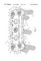
- FIG. 1is a view of the of the fixation system according to an embodiment of the present invention.
- FIGS. 2 a and 2 bare cross-sectional views of a fixation system installed according to a preferred embodiment of the present invention.
- FIG. 3is a view of the fixation system according to an embodiment of the present invention, as installed, as viewed facing the anterior surface.
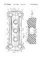
- FIG. 4is a detail view of the bone plate, seen facing the anterior surface.
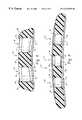
- FIG. 5is a cross-sectional view of the undercut fastener receiving opening and stress controlling ridges according to an embodiment of the present invention, taken along line 5 — 5 of FIG. 4 .
- FIG. 6is a cross-sectional view of a semi-rigid fixation bone screw according to an embodiment of the present invention.
- FIG. 7is a cross-sectional view of a rigid fixation bone screw according to an embodiment of the present invention.
- FIG. 8is a cross-sectional view of the plate, taken along line 8 — 8 of FIG. 4 .
- FIG. 9is a cross-sectional view of the plate, taken along line 9 — 9 of FIG. 4 .
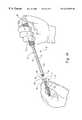
- FIG. 10is a perspective of the draw rod of the driving instrument of the present invention with a bone screw being loaded.
- FIG. 11is a view of the fixation system with fusion cage according to an embodiment of the present invention, as viewed facing the anterior surface.
- FIG. 12is a side view of the fixation system having a fusion cage of the present invention.
- FIG. 13is an axial view of the fixation system having a fusion cage of the present invention.
- FIG. 14is a posterior, isometric view of the fixation system having a fusion cage of the present invention.
- FIG. 15is an anterior, isometric view of the fixation system having a fusion cage of the present invention.
- FIG. 1shows an isometric view of a bone fixation system 10 according to an embodiment of the present invention.
- Bone fixation system 10is generally comprised of a bone plate 12 a plurality of fasteners such as semi-rigid screws 14 and/or a plurality of rigid screws 16 . Fully assembled, semi-rigid screws 14 and/or rigid screws 16 are inserted through fastener receiving openings 18 formed in the bone plate 12 and driven into a bone structure.
- FIGS. 2 a and 2 billustrate the bone fixation system 10 as attached to vertebral bodies V 1 and V 2 .
- bone fixation system 10is configured for fixation to the human cervical spine by means of an anterior approach but it would be known to one skilled in the art that a present invention is readily adaptable to other bone configurations including other spinal locations.
- the bone plate 10is generally comprised of two end portions 20 , 22 , a bridge portion 24 , an anterior surface 26 , a posterior surface 28 , and one or more fastener receiving openings 18 .
- Bone plate 12has a length sufficient to span at least the space between two vertebrae. It should be appreciated, however, that applications for the present invention are considered where the bone plate 12 does not have such length limitation. It should also be appreciated that the length required for bone plate 12 in any particular installation is dependent upon the condition to be corrected which can include any number of vertebrae to be held in a desired spatial relationship relative to each other by the bone plate 12 .
- the bone plate 12is made from radiolucent composite polymer material, but it is contemplated that one of skill in the art would readily appreciate that the bone plate 12 may be made from a radiopaque material.
- Radiolucent composite materials that can be utilizedinclude carbon-fiber reinforced polymer composites from the polyaryletherketone family (i.e.—polyetheretherketone (PEEK), polyetherketoneetherketoneketone (PEKEKK), etc.).
- the composite polymer bone plate materialis composed of approximately 70% polyetheretherketone and 30% chopped carbon fiber with the chopped carbon fiber oriented randomly in order to obtain minimal anisotropic behavior.
- the polymer compositecan be processed to form the bone plate 12 by injection molding the composite into raw material blocks which are then machined into finished parts, such as bone plates. If desired, finished parts may be further processed by bending the parts into other shapes. Since the composite base resin is thermoplastic, parts made from the base resin can be easily deformed when raised above the resin's transition temperature. It is further contemplated that parts may be molded to a near-finished shape in order to reduce and possibly eliminate the required machining.
- the bone plate 12preferably has a stock width, taken along line 8 — 8 of FIG. 4, of approximately 18.75 mm with a stock length that varies from 20.0 mm overall to 94.0 mm overall, in a variety of increments.
- the incremental stock lengths currently availableare: 20, 22, 24, 26, 28, 30, 32, 34, 36, 39, 42, 45, 48, 51, 54, 57, 60, 63, 67, 71, 75, 78, 82, 86, 90, and 94 mm, respectively.
- the lengthsrepresent off-the-shelf stock lengths and do not limit the length of the bone plate 12 in any way. It is contemplated that longer or shorter plates can be readily used as patient need warrants.
- the bone plate 12has radii of curvature in the longitudinal direction for both the anterior and posterior sides of the bone plate 12 as well as having curvature in the transverse direction.
- the transverse direction radius of curvatureis typically only in the posterior surface, but it can be optionally placed in the anterior surface is so desired.
- the stock radii of curvature in the longitudinal directionare approximately 147 mm, 197 mm, and 247 mm, respectively.
- the radius of curvature in the transverse directionis about 40.6 mm.
- the bone plate 12may be optionally contoured through heating and bending to make nearly any form desired. Thus, it should be readily understood that a bone plate can be manufactured having more than one radius of curvature or other bend, etc.
- the fasteners 14 , 16can be produced from radiopaque material, such as commercially pure titanium or titanium alloy. It should be readily appreciated that other combinations of materials also may be used to produce the device, including radiolucent materials such as carbon fiber composites.
- End portions 20 , 22 of bone plate 10include a pair of openings 18 which are dimensioned to receive a fastener namely, semi-rigid screw 14 or rigid screw 16 .
- Each fastener receiving opening 18can be generally circular and have a smaller hole section 30 , an undercut 32 , a larger hole section 34 , and a lead-in chamfer 36 .
- the lead-in chamfer 36 and larger hole section 34are dimensioned to receive a head portion of either semi-rigid screw 14 or rigid screw 16 by means of snap-fitting therein.
- the undercut 32which is preferably spherically concave in configuration, is dimensioned to accommodate and retain the head portion of semi-rigid screw 14 or rigid screw 16 .
- the undercut 32may alternately be located on the head of the fastener.
- the undercut 32can also have virtually any geometrical configuration, including, but not limited to, rectangular, octagonal, hexagonal, triangular, circular, cylindrical, elliptical or any other polygonal.
- the fastener receiving openings 18 in the bone plate 12could have mating protrusions, rather than undercuts. Multiple undercuts or protrusions may also be provided in either or both the fastener or the plate.
- smaller hole section 30is dimensioned to have a diameter greater than semi-rigid screw shank 38 such that semi-rigid screw 14 rotates after a head portion 40 of semi-rigid screw 14 is received and retained by spherical concave undercut 32 .
- smaller hole section 30is dimensioned to have diameter approximately equal to diameter of a rigid screw shank 42 such that rigid screw 16 cannot demonstrate appreciable movement when a head portion 44 of rigid screw 16 is received and retained by spherical concave undercut 32 .
- Smaller hole section 30is dimensioned such that head portion 40 or head portion 44 is prevented from passing through.
- the undercut 32is preferably spherically concave, any number of configurations can be used, including, but not limited to, square, triangular, or irregular.
- the undercut 32simply should have at least a rim portion having a diameter smaller than that of the head portion of the screw such that the head portion elastically deforms when initially engaging the undercut 32 and then snaps into place so that it is held captive within the undercut 32 .
- Producing the device from the above listed materials and in the aforementioned mannerallows the tolerances of the components to be such that the head portion 40 , 44 of a screw 14 , 16 snaps into an undercut portion 32 of the fastener receiving openings 18 of the bone plate 12 with an amount of force appropriate for the surgical arena.
- the force required to engage the snap fitis large enough that the screw head is securely held, but not so large that there is danger of the bone screw stripping the thread in the bone.
- a semi-rigid screw 14is generally comprised of a head portion 40 , a shank 38 , a slot 46 , an internal thread 48 , an external thread 50 and a lead-in minor root taper 52 .
- Head portion 40is generally spherical. Spherical diameter of head portion 40 is generally equal to spherical diameter of spherical concave undercut 32 .
- Shank portion 38has a diameter that is smaller than diameter of smaller hole section 30 .
- External thread 50has a diameter that is smaller than diameter of smaller hole section 30 . If so desired, lead-in minor root taper 52 may be formed at end of external thread 50 .
- Slot portion 46is dimensioned to receive nubs of a driver housing. Internal thread portion 48 mates with an external thread portion of a draw rod.
- Rigid screw 16is comprised of a head portion 44 , a shank 42 , a slot 54 , an internal thread 56 , an external thread 58 and a washout minor root taper 60 .
- Head portion 44is generally spherical. Spherical diameter of head portion 44 is generally equal to the spherical diameter of spherical concave undercut 32 .
- Shank portion 42has a diameter that is generally equal to diameter of smaller hole section 30 .
- External thread 58has a diameter that is smaller than diameter of smaller hole section 30 .
- Washout minor root taper 60may be formed at end of external thread 58 .
- Slot portion 54is dimensioned to receive nubs of a driver housing. Internal thread portion 56 can mate with an external thread portion of a draw rod.
- a cancellous threadis preferred, but not required.
- a cancellous threadis deeply cut with a large pitch in order to allow extra purchase or anchorage in bone structures of poor quality.
- FIG. 10generally illustrates a fastener driver 70 generally comprising driver housing 72 and draw rod 74 .
- Driver housing 72has a cannulated shaft 76 , driver housing handle 78 and nubs 80 while draw rod 74 has external thread 82 , draw rod shaft 84 and draw rod handle 86 .
- Nubs 80are dimensioned to be received into slot portion 46 of semi-rigid screw 14 and into slot portion 54 of rigid screw 16 .
- Cannulated shaft 76is dimensioned to receive draw rod shaft 84 .
- An end of draw rod shafthas an externally threaded portion 82 that mates with internal thread 48 of semi-rigid screws 14 or internal thread 56 of rigid screws 16 .
- the driver 70works by inserting draw rod shaft 84 through cannulated shaft 76 .
- Nubs 80are received by slot 46 or slot 54 .
- Handle 86is rotated to engage external thread 82 with internal threads 48 or internal threads 56 .
- Engaging of external thread 82causes screw 14 or screw 16 to be pulled snugly against driver housing 72 .
- Draw rod shaft 84 and cannulated shaft 76are dimensioned such that tension is generated on the draw rod 74 to hold the screw 14 or the screw 16 firmly in place.
- the fixation system 10is installed by placing plate 12 of appropriate length, across the bone elements to be fixed. Posterior surface 28 contacts the bone elements. Anterior surface 26 faces surgeon. A hole is drilled relatively concentric to one of the fastener receiving openings 18 formed in plate 12 .
- Semi-rigid screw 14 or rigid screw 16is loaded onto driving instrument 70 .
- Driving instrument 70is rotated to engage semi-rigid screw 14 or rigid screw 16 with bone.
- Driving instrument 70is rotated until head 40 or head 44 contacts lead-in chamfer 36 .
- Further rotating driving instrument 70engages head 40 or head 44 to engage spherical concave undercut 32 . Head 40 or head 44 is received and retained in spherical concave undercut 32 .
- Additional semi-rigid screws 14 or rigid screws 16are installed to complete the installation process of the fixation system 10 .
- ridgesare included on the bone plate to reduce stress on the fastener receiving openings 18 and increase the fatigue life of the bone plate.
- Anterior surface 26has stress-controlling ridges 90 situated further from the neutral axis of plate 12 than a recessed surface 92 with anterior surface 26 being relatively convex. It should be appreciated that one could use a single stress-controlling ridge as well as a plurality of the ridges depending on the deployment location of the ridges 90 on the plate. Furthermore, such stress-controlling ridges may be located on the posterior surface as well as the more typical anterior surface deployment.
- posterior surface 28is relatively concave and relatively smooth. It should be further appreciated that several forms of surface modifications are contemplated for posterior surface 28 . Surface modifications contemplated include roughening the surface or making the surface porous to encourage bone ingrowth, as well as adding spikes, teeth, holes for bone ingrowth, or through holes for receiving wires, cables, nails, or sutures. Further contemplated surface modifications include treatments with bone-growth factors or other tissue-growth factors to enhance the healing process.
- FIGS. 11-15an embodiment of the present bone fixation system 100 is provided having a fusion cage 102 incorporated into bone plate 104 .
- Fusion cagesare used to promote fusion of the injured area and speed healing. In the present embodiment, this is accomplished by inserting, packing or impregnating bone graft tissue into a graft receiving area 106 of the fusion cage 102 . After fixing the bone plate 104 to the vertebrae, the bone tissue graft will grow out through the openings or vascular windows 108 of the graft receiving area 106 to ultimately fuse with the healing vertebrae.
- the fusion cage embodiment 100 of the present inventiongenerally comprises a fusion cage 102 , bone plate 104 , a graft receiving area 106 having a plurality of vascular windows 108 therethrough and fastener receiving openings 110 , 112 for receiving bone screws or other such fasteners.
- the bone plate 104 of the fusion cage embodiment 100has an anterior surface 114 , a posterior surface 116 , a caudal end 118 and a cephalad end 120 .
- Fastener holes 110 , 112may have undercuts incorporated therein, and as described previously, are located through the bone plate 104 .
- backoutis greatly reduced, if not eliminated altogether, because loads placed on the device will transfer to and be borne by the graft receiving area 106 which is lodged between the vertebrae.
- Cephalad fastener receiving openings 110are angled so as the cephalad fasteners 122 are inserted through their respective holes 110 and into the bone to be treated, they are driven in the cephalad direction.
- the cephalad fasteners 122are also preferably angled slightly toward an imaginary centerline of the bone plate 104 , so that upon insertion, the cephalad fasteners 122 inserted into the cephalad fastener receiving openings 110 form a triangular wedge construct.
- the cephalad fastener receiving openings 110 and fastenersmay utilize the snap-fit engagement of a head portion of the screw into an undercut located in the screw hole in a manner identical to that previously described.
- the caudal fastener receiving openings 112receive caudal fasteners or bone screws 124 which may “snap-fit” or engage respective undercuts in the caudal screw holes 112 . Note, however, such snap-fit undercuts are not required, but if utilized are implemented as described above.
- the graft receiving area 106 of the fusion cage 102may have one or more vascular windows 108 incorporated therethrough.
- the vascular windows 108have a circular configuration in which the outside edges are counter-sunk as a stress reducing feature.
- the counter-sunk featureis non-critical and that the windows may have any number of configurations. Exemplary, but by no means limiting, configurations include ovals, hexagons, squares and even a single, large window.
- the graft receiving area 106 of the fusion cagemay also have endplate angles 126 , 128 in both the cephalad and caudal directions.
- the angles 126 , 128are designed to rest against the vertebral endplate of a vertebra being treated.
- the angles 126 , 128may be included to maintain lordotic fit between the fusion cage 102 and the vertebral column.
- FIG. 12demonstrates that the angles are approximately 10°, but this angulation may change in either direction in order to improve the fit of the bone plate and may even be negative, depending upon the orientation of the vertebrae being treated.
- the posterior surface 116 of the bone plate 104may have a curvature designed to mirror the vertebral topology.
- Such use of contoured surfaces to mate with vertebral bodiesis further described in U.S. patent application Ser. No. 09/114,996, incorporated by reference herein.
Landscapes
- Health & Medical Sciences (AREA)
- Orthopedic Medicine & Surgery (AREA)
- Life Sciences & Earth Sciences (AREA)
- Surgery (AREA)
- Engineering & Computer Science (AREA)
- Biomedical Technology (AREA)
- General Health & Medical Sciences (AREA)
- Neurology (AREA)
- Veterinary Medicine (AREA)
- Heart & Thoracic Surgery (AREA)
- Public Health (AREA)
- Animal Behavior & Ethology (AREA)
- Molecular Biology (AREA)
- Medical Informatics (AREA)
- Nuclear Medicine, Radiotherapy & Molecular Imaging (AREA)
- Cardiology (AREA)
- Oral & Maxillofacial Surgery (AREA)
- Transplantation (AREA)
- Vascular Medicine (AREA)
- Surgical Instruments (AREA)
Abstract
Description
Claims (24)
Priority Applications (1)
| Application Number | Priority Date | Filing Date | Title |
|---|---|---|---|
| US09/322,545US6342055B1 (en) | 1999-04-29 | 1999-05-28 | Bone fixation system |
Applications Claiming Priority (2)
| Application Number | Priority Date | Filing Date | Title |
|---|---|---|---|
| US13148399P | 1999-04-29 | 1999-04-29 | |
| US09/322,545US6342055B1 (en) | 1999-04-29 | 1999-05-28 | Bone fixation system |
Publications (1)
| Publication Number | Publication Date |
|---|---|
| US6342055B1true US6342055B1 (en) | 2002-01-29 |
Family
ID=26829520
Family Applications (1)
| Application Number | Title | Priority Date | Filing Date |
|---|---|---|---|
| US09/322,545Expired - LifetimeUS6342055B1 (en) | 1999-04-29 | 1999-05-28 | Bone fixation system |
Country Status (1)
| Country | Link |
|---|---|
| US (1) | US6342055B1 (en) |
Cited By (237)
| Publication number | Priority date | Publication date | Assignee | Title |
|---|---|---|---|---|
| US20020147499A1 (en)* | 2001-02-26 | 2002-10-10 | Shea Jeffrey J. | Locking systems for implants |
| US20020183754A1 (en)* | 2001-06-04 | 2002-12-05 | Michelson Gary K. | Anterior cervical plate system having vertebral body engaging anchors, connecting plate, and method for installation thereof |
| US20020183755A1 (en)* | 2001-06-04 | 2002-12-05 | Michelson Gary K. | Dynamic anterior cervical plate system having moveable segments, instrumentation, and method for installation thereof |
| US20020188296A1 (en)* | 2001-06-06 | 2002-12-12 | Michelson Gary K. | Dynamic, modular, multilock anterior cervical plate system having detachably fastened assembleable and moveable segments, instrumentation, and method for installation thereof |
| US20030018335A1 (en)* | 1997-02-11 | 2003-01-23 | Michelson Gary K. | Anterior cervical plate system |
| US20030060828A1 (en)* | 2001-06-06 | 2003-03-27 | Michelson Gary K. | Dynamic multilock anterior cervical plate system having non-detachably fastened and moveable segments, instrumentation, and method for installation thereof |
| US6558423B1 (en) | 1999-05-05 | 2003-05-06 | Gary K. Michelson | Interbody spinal fusion implants with multi-lock for locking opposed screws |
| US20030181911A1 (en)* | 2000-08-31 | 2003-09-25 | Daniele Venturini | External splint device for reducing bone fractures |
| US6626945B2 (en)* | 2000-03-14 | 2003-09-30 | Chondrosite, Llc | Cartilage repair plug |
| US6656181B2 (en)* | 2000-11-22 | 2003-12-02 | Robert A Dixon | Method and device utilizing tapered screw shanks for spinal stabilization |
| US6666870B2 (en)* | 2001-01-05 | 2003-12-23 | Robert A Dixon | Method utilizing chemical bonding to improve the bone screw fixation interface |
| US20040034353A1 (en)* | 1994-03-28 | 2004-02-19 | Michelson Gary Karlin | Apparatus and method for anterior spinal stabilization |
| US6695845B2 (en)* | 2000-10-16 | 2004-02-24 | Robert A Dixon | Method and apparatus utilizing interference fit screw shanks for nonmetallic spinal stabilization |
| US20040039387A1 (en)* | 2002-08-22 | 2004-02-26 | Larry Gause | System for stabilizing a portion of the spine |
| EP1393689A3 (en)* | 1997-02-11 | 2004-03-17 | MICHELSON, Gary Karlin | Anterior cervical plating system and bone screw |
| US6730127B2 (en)* | 2000-07-10 | 2004-05-04 | Gary K. Michelson | Flanged interbody spinal fusion implants |
| US20040102788A1 (en)* | 2002-11-19 | 2004-05-27 | Huebner Randall J. | Guide system for bone-repair devices |
| US20040102778A1 (en)* | 2002-11-19 | 2004-05-27 | Huebner Randall J. | Adjustable bone plates |
| US20040116930A1 (en)* | 2002-06-10 | 2004-06-17 | O'driscoll Shawn W. | Bone plates |
| US20040127904A1 (en)* | 2002-12-31 | 2004-07-01 | Konieczynski David D. | Bone plate and resilient screw system allowing bi-directional assembly |
| US20040127899A1 (en)* | 2002-12-31 | 2004-07-01 | Konieczynski David D. | Bone plate and screw system allowing bi-directional attachment |
| US20040127900A1 (en)* | 2002-12-31 | 2004-07-01 | Konieczynski David D. | Resilient bone plate and screw system allowing bi-directional assembly |
| US20040162622A1 (en)* | 2000-03-14 | 2004-08-19 | Chondosite, Llc | Cartilage repair plug |
| US20040181226A1 (en)* | 2001-06-04 | 2004-09-16 | Michelson Gary K. | Method for installing dynamic, modular, single-lock anterior cervical plate system having assembleable and moveable segments |
| US20040181229A1 (en)* | 2001-06-04 | 2004-09-16 | Michelson Gary K. | Instrumentation for use with dynamic single-lock anterior cervical plate system having non-detachably fastened and moveable segments |
| US20040204717A1 (en)* | 2003-04-09 | 2004-10-14 | Jonathan Fanger | Guide for spinal tools, implants, and devices |
| US20040204710A1 (en)* | 2003-04-09 | 2004-10-14 | Tushar Patel | Drill guide and plate inserter |
| US20040204712A1 (en)* | 2003-04-09 | 2004-10-14 | Eric Kolb | Bone fixation plates |
| US20040210218A1 (en)* | 2001-10-15 | 2004-10-21 | Dixon Robert A. | Vertebral implant for bone fixation or interbody use |
| US20040210217A1 (en)* | 2003-04-21 | 2004-10-21 | Baynham Bret O'neil | Bone fixation plate |
| US20040215195A1 (en)* | 2003-04-25 | 2004-10-28 | Sdgi Holdings, Inc. | Non-metallic orthopedic plate |
| US20040215192A1 (en)* | 2000-03-01 | 2004-10-28 | Justis Jeff R | Superelastic spinal stabilization system and method |
| US20040220572A1 (en)* | 1997-02-11 | 2004-11-04 | Michelson Gary K | Skeletal plating system |
| US20040260291A1 (en)* | 2003-06-20 | 2004-12-23 | Jensen David G. | Bone plates with intraoperatively tapped apertures |
| DE10326643A1 (en)* | 2003-06-11 | 2004-12-30 | Mückter, Helmut, Dr. med. Dipl.-Ing. | Osteosynthesis plate or comparable implant with ball sleeve |
| US20050033298A1 (en)* | 2001-10-31 | 2005-02-10 | Ortho Development Corporation | Cervical plate for stabilizing the human spine |
| US20050049593A1 (en)* | 2003-09-03 | 2005-03-03 | Duong Lan Anh Nguyen | Bone plate with captive clips |
| US20050049595A1 (en)* | 2003-09-03 | 2005-03-03 | Suh Sean S. | Track-plate carriage system |
| US20050059970A1 (en)* | 2003-09-17 | 2005-03-17 | Eric Kolb | Bone fixation systems |
| US20050085819A1 (en)* | 2003-08-28 | 2005-04-21 | Ellis Thomas J. | Bone plates |
| US20050131413A1 (en)* | 2003-06-20 | 2005-06-16 | O'driscoll Shawn W. | Bone plate with interference fit screw |
| US20050149019A1 (en)* | 2003-12-19 | 2005-07-07 | Sasing Jude L. | Transverse connector for rod-based spinal implants |
| US20050171544A1 (en)* | 2004-02-02 | 2005-08-04 | Acumed Llc | Bone plate with toothed aperture |
| US20050177161A1 (en)* | 2004-02-10 | 2005-08-11 | Baynham Bret O. | Static anterior cervical plate |
| US20050216008A1 (en)* | 2004-03-24 | 2005-09-29 | Zwirnmann Ralph F | Bone fixation implants |
| US20050216027A1 (en)* | 2004-03-24 | 2005-09-29 | Suh Sean S | Extraction screwdriver |
| US20050228386A1 (en)* | 2004-04-08 | 2005-10-13 | Tara Ziolo | Bone fixation device |
| US20050234472A1 (en)* | 2004-04-19 | 2005-10-20 | Huebner Randall J | Placement of fasteners into bone |
| US20050234458A1 (en)* | 2004-04-19 | 2005-10-20 | Huebner Randall J | Expanded stabilization of bones |
| US20050240187A1 (en)* | 2004-04-22 | 2005-10-27 | Huebner Randall J | Expanded fixation of bones |
| US20050240185A1 (en)* | 2004-04-23 | 2005-10-27 | Depuy Spine Sarl | Spinal fixation plates and plate extensions |
| WO2005112802A1 (en)* | 2004-05-21 | 2005-12-01 | Synthes (Usa) | Bone plate |
| US6974461B1 (en)* | 1999-09-14 | 2005-12-13 | Dietmar Wolter | Fixation system for bones |
| US20050283152A1 (en)* | 2004-06-17 | 2005-12-22 | Lindemann Gary S | Method and apparatus for retaining screws in a plate |
| US20050288673A1 (en)* | 2003-12-19 | 2005-12-29 | Adrian Catbagan | Low profile anterior thoracic and thoracolumbar plate |
| US20060036250A1 (en)* | 2004-08-12 | 2006-02-16 | Lange Eric C | Antero-lateral plating systems for spinal stabilization |
| US20060036249A1 (en)* | 2004-08-12 | 2006-02-16 | Baynham Bret O | Bone plate with screw lock |
| US20060142771A1 (en)* | 2003-06-11 | 2006-06-29 | Florian Beutter | Bone clamp |
| USD524443S1 (en) | 2005-11-04 | 2006-07-04 | Quantum Orthopedics, Inc. | Interbody fusion device |
| US20060149255A1 (en)* | 2005-01-06 | 2006-07-06 | Doubler Robert L | Spinal implant kit |
| US20060149253A1 (en)* | 2005-01-06 | 2006-07-06 | Doubler Robert L | Spinal plate with internal screw locks |
| US20060161157A1 (en)* | 2004-02-26 | 2006-07-20 | Lawrence Mosca | Bone plate system and methods |
| US20060167456A1 (en)* | 2004-12-21 | 2006-07-27 | Packaging Service Corporation Of Kentucky | Cervical plate system |
| US20060189982A1 (en)* | 2001-03-09 | 2006-08-24 | Robert Lange | Longitudinal implant |
| US20060235533A1 (en)* | 2005-03-17 | 2006-10-19 | Jason Blain | Flanged interbody fusion device with hinge |
| US20060235405A1 (en)* | 2005-03-31 | 2006-10-19 | Hawkes David T | Active compression orthopedic plate system and method for using the same |
| US20060235400A1 (en)* | 2003-08-26 | 2006-10-19 | Rolf Schneider | Bone plate |
| US20060242813A1 (en)* | 2005-04-29 | 2006-11-02 | Fred Molz | Metal injection molding of spinal fixation systems components |
| US20060247638A1 (en)* | 2005-04-29 | 2006-11-02 | Sdgi Holdings, Inc. | Composite spinal fixation systems |
| USD533277S1 (en) | 2005-11-04 | 2006-12-05 | Quantum Orthopedics, Inc. | Interbody fusion device |
| US20060276793A1 (en)* | 2005-05-26 | 2006-12-07 | Amedica Corporation | Bone fixation plate with self-locking screws |
| US20060293668A1 (en)* | 2005-06-10 | 2006-12-28 | Sdgi Holdings, Inc. | Bone screw locking mechanism and method of use |
| US20070016204A1 (en)* | 2005-07-14 | 2007-01-18 | Medical Device Concepts Llc. | Spinal buttress device and method |
| US20070016301A1 (en)* | 2005-07-14 | 2007-01-18 | Medical Device Concepts Llc. | Multi-axial interbody spacer device |
| US20070016190A1 (en)* | 2005-07-14 | 2007-01-18 | Medical Device Concepts Llc | Dynamic spinal stabilization system |
| US20070055249A1 (en)* | 2003-06-20 | 2007-03-08 | Jensen David G | Bone plates with intraoperatively tapped apertures |
| US20070055250A1 (en)* | 2005-07-11 | 2007-03-08 | Kamran Aflatoon | Cervical plates with spacer mechanism |
| US20070055380A1 (en)* | 2005-09-08 | 2007-03-08 | Biomet Manufacturing Corp | Method and apparatus for a glenoid prosthesis |
| US7189237B2 (en) | 2002-11-19 | 2007-03-13 | Acumed Llc | Deformable bone plates |
| US20070073297A1 (en)* | 2005-09-15 | 2007-03-29 | Joseph Reynolds | Implant with integral fastener retention |
| US7204837B2 (en) | 2001-12-14 | 2007-04-17 | Paul Kamaljit S | Spinal plate assembly |
| US20070123879A1 (en)* | 2003-02-05 | 2007-05-31 | Pioneer Laboratories, Inc. | Bone plate system |
| US20070123873A1 (en)* | 2005-10-31 | 2007-05-31 | Czartoski Timothy J | Intramedullary nail with oblique openings |
| US20070123871A1 (en)* | 2003-09-24 | 2007-05-31 | Tae-Ahn Jahng | Method and apparatus for flexible fixation of a spine |
| US20070162016A1 (en)* | 2005-10-25 | 2007-07-12 | Matityahu Amir M | Bone fastening assembly and bushing and screw for use therewith |
| US20070162018A1 (en)* | 2002-07-22 | 2007-07-12 | Jensen David G | Orthopedic systems |
| US20070162019A1 (en)* | 2005-12-21 | 2007-07-12 | Paul Burns | Resorbable anterior cervical plating system with screw retention mechanism |
| US20070173843A1 (en)* | 2005-12-22 | 2007-07-26 | Matityahu Amir M | Drug delivering bone plate and method and targeting device for use therewith |
| US7255699B2 (en) | 2001-12-14 | 2007-08-14 | Paul Kamaljit S | Spinal plate assembly |
| US7278997B1 (en) | 2003-03-07 | 2007-10-09 | Theken Spine, Llc | Instrument guide and implant holder |
| US20070270851A1 (en)* | 2006-04-28 | 2007-11-22 | David Erickson | Radiolucent bone plate systems and methods of use |
| US20070276380A1 (en)* | 2003-09-24 | 2007-11-29 | Tae-Ahn Jahng | Spinal stabilization device |
| US7309340B2 (en) | 2003-06-20 | 2007-12-18 | Medicinelodge, Inc. | Method and apparatus for bone plating |
| US7320708B1 (en) | 2002-11-13 | 2008-01-22 | Sdgi Holdings, Inc. | Cervical interbody device |
| US7341591B2 (en) | 2003-01-30 | 2008-03-11 | Depuy Spine, Inc. | Anterior buttress staple |
| US20080077141A1 (en)* | 2006-09-26 | 2008-03-27 | Bray Robert S | Cervical dynamic stabilization system |
| US20080154310A1 (en)* | 2006-12-21 | 2008-06-26 | Warsaw Orthopedic, Inc. | Reinforced orthopedic plate |
| US20080172095A1 (en)* | 2007-01-11 | 2008-07-17 | Salerni Anthony A | Bone Loss Plate |
| US20080188852A1 (en)* | 2007-02-05 | 2008-08-07 | Matityahu Amir M | Apparatus for Repositioning Portions of Fractured Bone and Method of Using Same |
| US20080208263A1 (en)* | 2007-02-26 | 2008-08-28 | Butler Michael S | Spine plate with configured bone screw bores |
| US20080234677A1 (en)* | 2007-03-21 | 2008-09-25 | The University Of North Carolina At Chapel Hill Anglefix Tech, Llc | Anti-unscrewing and multi-angular fastening apparatuses and methods for surgical bone screw/plate systems |
| US20080234752A1 (en)* | 2007-03-21 | 2008-09-25 | The University Of North Carolina At Chapel Hill | Surgical plate puller devices and methods for use with surgical bone screw/plate systems |
| US20080306550A1 (en)* | 2007-06-07 | 2008-12-11 | Matityahu Amir M | Spine repair assembly |
| US20090012571A1 (en)* | 2007-07-03 | 2009-01-08 | Pioneer Surgical Technology, Inc. | Bone Plate System |
| US20090054930A1 (en)* | 2007-08-20 | 2009-02-26 | Kamran Aflatoon | Anterior cervical staple |
| US20090062862A1 (en)* | 2007-07-03 | 2009-03-05 | Pioneer Surgical Technology, Inc. | Bone Plate System |
| US20090069812A1 (en)* | 2007-06-15 | 2009-03-12 | Acumed Llc | Rib fixation with an intramedullary nail |
| US20090099602A1 (en)* | 2007-09-11 | 2009-04-16 | Kamran Aflatoon | Method of lateral facet approach, decompression and fusion using screws and staples as well as arthroplasty |
| US7537603B2 (en) | 2002-07-22 | 2009-05-26 | Acumed Llc | Bone fusion system |
| US7537604B2 (en) | 2002-11-19 | 2009-05-26 | Acumed Llc | Bone plates with slots |
| US20090171396A1 (en)* | 2003-04-21 | 2009-07-02 | Baynham Matthew G | Bone fixation plate |
| US20090182431A1 (en)* | 2008-01-16 | 2009-07-16 | Butler Michael S | Spinal Interbody Fusion Cages Providing Variable Anterior/Posterior Profiles |
| US20090270927A1 (en)* | 2008-04-25 | 2009-10-29 | Pioneer Surgical Technology, Inc. | Bone Plate System |
| USD603507S1 (en) | 2008-07-03 | 2009-11-03 | Theken Spine, Llc | Cervical plate |
| USD603504S1 (en) | 2008-07-03 | 2009-11-03 | Theken Spine, Llc | Cervical plate |
| USD603506S1 (en) | 2008-07-03 | 2009-11-03 | Theken Spine, Llc | Cervical plate |
| USD603510S1 (en) | 2008-07-03 | 2009-11-03 | Theken Spine, Llc | Cervical plate |
| USD603503S1 (en) | 2008-07-03 | 2009-11-03 | Theken Spine, Llc | Cervical plate |
| USD603508S1 (en) | 2008-07-03 | 2009-11-03 | Theken Spine, Llc | Cervical plate |
| USD603511S1 (en) | 2008-07-03 | 2009-11-03 | Theken Spine, Llc | Cervical plate |
| USD603509S1 (en) | 2008-07-03 | 2009-11-03 | Theken Spine, Llc | Cervical plate |
| USD603505S1 (en) | 2008-07-03 | 2009-11-03 | Theken Spine, Llc | Cervical plate |
| USD603962S1 (en) | 2008-07-03 | 2009-11-10 | Theken Spine, Llc | Cervical plate |
| USD603964S1 (en) | 2008-07-03 | 2009-11-10 | Theken Spine, Llc | Cervical plate |
| USD603963S1 (en) | 2008-07-03 | 2009-11-10 | Theken Spine, Llc | Cervical plate |
| USD603961S1 (en) | 2008-07-03 | 2009-11-10 | Theken Spine, Llc | Cervical plate |
| US20090312803A1 (en)* | 2003-09-29 | 2009-12-17 | Austin Gene E | Bone Plate and Bone Plate Assemblies Including Polyaxial Fasteners |
| US20090326580A1 (en)* | 2008-06-25 | 2009-12-31 | Anderson Mark E | Spinal fixation device |
| US20100016858A1 (en)* | 2008-07-21 | 2010-01-21 | Gerlinde Michel | Carbon Fiber Reinforced Peek Bone Plate With Titanium Fixation Screws |
| US20100063550A1 (en)* | 2008-09-11 | 2010-03-11 | Innovasis, Inc, | Radiolucent screw with radiopaque marker |
| US20100076496A1 (en)* | 2004-01-26 | 2010-03-25 | Alberto Angel Fernandez | Variable Angle Locked Bone Fixation System |
| US20100152783A1 (en)* | 2008-12-11 | 2010-06-17 | Veterinary Implants Direct, Llc | Universal Surgical Plate with 30 Degree Compression Angle |
| US7766911B1 (en) | 2002-07-05 | 2010-08-03 | Theken Spine, Llc | Fixed and variable locking fixation assembly |
| US20100217328A1 (en)* | 2009-02-24 | 2010-08-26 | Osteomed L.P. | Multiple Bone Fusion Plate |
| US20100249935A1 (en)* | 2009-03-30 | 2010-09-30 | Slivka Michael A | Zero Profile Spinal Fusion Cage |
| US20100249937A1 (en)* | 2009-03-27 | 2010-09-30 | Spinal Elements, Inc. | Flanged interbody fusion device |
| US20100274293A1 (en)* | 2009-04-28 | 2010-10-28 | Osteomed L.P. | Bone Plate with a Transfixation Screw Hole |
| US20110004253A1 (en)* | 2003-03-31 | 2011-01-06 | Depuy Spine, Inc. | Spinal fixation plate |
| US20110022173A1 (en)* | 2009-07-24 | 2011-01-27 | Warsaw Orthopedic, Inc. | Implant with an interference fit fastener |
| US7887595B1 (en) | 2005-12-05 | 2011-02-15 | Nuvasive, Inc. | Methods and apparatus for spinal fusion |
| US20110060365A1 (en)* | 2009-09-10 | 2011-03-10 | Innovasis, Inc. | Radiolucent stabilizing rod with radiopaque marker |
| US7909860B2 (en) | 2003-09-03 | 2011-03-22 | Synthes Usa, Llc | Bone plate with captive clips |
| US7909848B2 (en) | 2003-06-27 | 2011-03-22 | Depuy Spine, Inc. | Tissue retractor and guide device |
| US7909829B2 (en) | 2003-06-27 | 2011-03-22 | Depuy Spine, Inc. | Tissue retractor and drill guide |
| US20110071570A1 (en)* | 2009-09-24 | 2011-03-24 | Warsaw Orthopedic, Inc. | Composite vertebral rod system and methods of use |
| US7935123B2 (en) | 2003-04-09 | 2011-05-03 | Depuy Acromed, Inc. | Drill guide with alignment feature |
| US20110106157A1 (en)* | 2009-10-30 | 2011-05-05 | Warsaw Orthropedic, Inc. | Self-Locking Interference Bone Screw for use with Spinal Implant |
| US20110106167A1 (en)* | 2003-09-24 | 2011-05-05 | Tae-Ahn Jahng | Adjustable spinal stabilization system |
| AT508196B1 (en)* | 2009-04-29 | 2011-07-15 | Christian Dipl Ing Maier | FIXING SYSTEM FOR BONE WITH CONVEX DRILLING |
| US20110218570A1 (en)* | 2010-03-08 | 2011-09-08 | Innovasis, Inc. | Radiolucent bone plate with radiopaque marker |
| US20110218574A1 (en)* | 2010-03-03 | 2011-09-08 | Warsaw Orthopedic, Inc. | Dynamic vertebral construct |
| US20110224671A1 (en)* | 2009-09-14 | 2011-09-15 | Kenny Koay | Variable angle compression plate |
| US20110257730A1 (en)* | 2002-10-02 | 2011-10-20 | Boston Scientific Scimed, Inc. | Medical devices and methods of making the same |
| US20110282389A1 (en)* | 2010-05-17 | 2011-11-17 | Omni Surgical dba Spine 360 | Bone fixation plate assembly |
| US8114162B1 (en) | 2006-08-09 | 2012-02-14 | Nuvasive, Inc. | Spinal fusion implant and related methods |
| WO2012116819A1 (en)* | 2011-03-03 | 2012-09-07 | Zimmer, Inc | Bone screw with multiple thread profiles for far cortical locking and flexible engagement to a bone |
| US8328807B2 (en) | 2008-07-09 | 2012-12-11 | Icon Orthopaedic Concepts, Llc | Ankle arthrodesis nail and outrigger assembly |
| US8382807B2 (en) | 2005-07-25 | 2013-02-26 | Smith & Nephew, Inc. | Systems and methods for using polyaxial plates |
| US20130079829A1 (en)* | 2010-06-07 | 2013-03-28 | Carbofix Orthopedics Ltd. | Composite material bone implant |
| US8414584B2 (en) | 2008-07-09 | 2013-04-09 | Icon Orthopaedic Concepts, Llc | Ankle arthrodesis nail and outrigger assembly |
| US20130238028A1 (en)* | 2010-05-19 | 2013-09-12 | Desmond O'Farrell | Implantable vertebral frame systems and related methods for spinal repair |
| US20130274813A1 (en)* | 2001-12-24 | 2013-10-17 | DePuy Synthes Products, LLC | Device for osteosynthesis |
| US8562656B2 (en) | 2010-10-15 | 2013-10-22 | Warsaw Orrthopedic, Inc. | Retaining mechanism |
| US8568417B2 (en) | 2009-12-18 | 2013-10-29 | Charles River Engineering Solutions And Technologies, Llc | Articulating tool and methods of using |
| US8574268B2 (en) | 2004-01-26 | 2013-11-05 | DePuy Synthes Product, LLC | Highly-versatile variable-angle bone plate system |
| US8721643B2 (en) | 2005-08-23 | 2014-05-13 | Smith & Nephew, Inc. | Telemetric orthopaedic implant |
| USD708747S1 (en) | 2006-09-25 | 2014-07-08 | Nuvasive, Inc. | Spinal fusion implant |
| US20140277019A1 (en)* | 2013-03-15 | 2014-09-18 | Neuropace, Inc. | Surgical accessory for use in implanting medical device |
| US8858603B1 (en) | 2010-06-09 | 2014-10-14 | Choice Spine, L.P. | Cervical plate with screw retention clip |
| US8900277B2 (en) | 2004-02-26 | 2014-12-02 | Pioneer Surgical Technology, Inc. | Bone plate system |
| US8940028B2 (en) | 2005-07-25 | 2015-01-27 | Smith & Nephew, Inc. | Systems and methods for using polyaxial plates |
| RU2545424C2 (en)* | 2008-10-15 | 2015-03-27 | Смит Энд Нефью, Инк. | Composite inner retainer |
| US20150105827A1 (en)* | 2001-01-05 | 2015-04-16 | Stryker France | Pedicle screw assembly and methods therefor |
| US9198769B2 (en) | 2011-12-23 | 2015-12-01 | Pioneer Surgical Technology, Inc. | Bone anchor assembly, bone plate system, and method |
| US9237910B2 (en) | 2012-01-26 | 2016-01-19 | Acute Innovations Llc | Clip for rib stabilization |
| US9248028B2 (en) | 2011-09-16 | 2016-02-02 | DePuy Synthes Products, Inc. | Removable, bone-securing cover plate for intervertebral fusion cage |
| CN105455926A (en)* | 2015-12-23 | 2016-04-06 | 马向阳 | Vertebral plate interbody fusion cage |
| US9308034B2 (en) | 2003-05-30 | 2016-04-12 | DePuy Synthes Products, Inc. | Bone plate |
| CN105476704A (en)* | 2015-12-17 | 2016-04-13 | 周建明 | Anterior cervical plate fixation system |
| US9387025B2 (en) | 2012-04-04 | 2016-07-12 | Smith & Nephew, Inc. | Bone screw and self-retaining driver |
| US20160213405A1 (en)* | 2015-01-27 | 2016-07-28 | K2M, Inc. | Vertebral plate systems and methods of use |
| US9526549B2 (en) | 2012-01-16 | 2016-12-27 | Carbofix Orthopedics Ltd. | Bone screw with insert |
| US9572680B2 (en) | 2013-01-25 | 2017-02-21 | K2M, Inc. | Spinal implants, spinal implant kits, and surgical methods |
| US9662225B2 (en) | 2012-03-06 | 2017-05-30 | DePuy Synthes Products, Inc. | Nubbed plate |
| US9687354B2 (en) | 2008-03-26 | 2017-06-27 | DePuy Synthes Products, Inc. | Posterior intervertebral disc inserter and expansion techniques |
| CN106955147A (en)* | 2016-01-11 | 2017-07-18 | 董震 | A kind of orthopaedics lock screw |
| US20170202586A1 (en)* | 2015-12-11 | 2017-07-20 | DePuy Synthes Products, Inc. | Composite implant trial |
| US9775657B2 (en) | 2011-09-30 | 2017-10-03 | Acute Innovations Llc | Bone fixation system with opposed mounting portions |
| US9956015B2 (en) | 2014-07-03 | 2018-05-01 | Acumed Llc | Bone plate with movable joint |
| US10028777B2 (en) | 2009-01-16 | 2018-07-24 | Carbofix Orthopedics Ltd. | Composite material bone implant |
| US10123831B2 (en) | 2015-03-03 | 2018-11-13 | Pioneer Surgical Technology, Inc. | Bone compression device and method |
| US10154867B2 (en) | 2010-06-07 | 2018-12-18 | Carbofix In Orthopedics Llc | Multi-layer composite material bone screw |
| US10172716B1 (en)* | 2016-09-06 | 2019-01-08 | Choice Spine, Llc | Corpectomy spacer and plate |
| US10182921B2 (en) | 2012-11-09 | 2019-01-22 | DePuy Synthes Products, Inc. | Interbody device with opening to allow packing graft and other biologics |
| US10206787B2 (en) | 2006-12-22 | 2019-02-19 | Medos International Sarl | Composite vertebral spacers and instrument |
| CN109480994A (en)* | 2018-12-18 | 2019-03-19 | 北京爱康宜诚医疗器材有限公司 | Orthopaedics pedicle screw |
| USD847336S1 (en)* | 2017-10-31 | 2019-04-30 | Sicage Llc | Parallel surgical guide spacer |
| USD849947S1 (en) | 2017-09-01 | 2019-05-28 | Choice Spine, Llc | Corpectomy spacer |
| USD850616S1 (en) | 2017-10-31 | 2019-06-04 | Sicage Llc | Parallel surgical guide spacer |
| US10335289B2 (en) | 2010-09-23 | 2019-07-02 | DePuy Synthes Products, Inc. | Stand alone intervertebral fusion device |
| US10369015B2 (en) | 2010-09-23 | 2019-08-06 | DePuy Synthes Products, Inc. | Implant inserter having a laterally-extending dovetail engagement feature |
| US10390866B2 (en) | 2011-06-15 | 2019-08-27 | Smith & Nephew, Inc. | Variable angle locking implant |
| US10500062B2 (en) | 2009-12-10 | 2019-12-10 | DePuy Synthes Products, Inc. | Bellows-like expandable interbody fusion cage |
| US10603054B2 (en) | 2017-10-31 | 2020-03-31 | Sicage Llc | Parallel guide for surgical implants |
| US10617458B2 (en) | 2015-12-23 | 2020-04-14 | Carbofix In Orthopedics Llc | Multi-layer composite material bone screw |
| US10624686B2 (en) | 2016-09-08 | 2020-04-21 | DePuy Synthes Products, Inc. | Variable angel bone plate |
| US10758361B2 (en) | 2015-01-27 | 2020-09-01 | Spinal Elements, Inc. | Facet joint implant |
| US10765527B2 (en) | 2017-09-29 | 2020-09-08 | Axiomed, LLC | Artificial disk with sensors |
| US10765461B2 (en) | 2018-06-01 | 2020-09-08 | DePuy Synthes Products, Inc. | Variable angle bone fixation device |
| US10772665B2 (en) | 2018-03-29 | 2020-09-15 | DePuy Synthes Products, Inc. | Locking structures for affixing bone anchors to a bone plate, and related systems and methods |
| US10820930B2 (en) | 2016-09-08 | 2020-11-03 | DePuy Synthes Products, Inc. | Variable angle bone plate |
| US10849764B2 (en) | 2015-01-27 | 2020-12-01 | K2M, Inc. | Interbody spacer |
| US10905476B2 (en) | 2016-09-08 | 2021-02-02 | DePuy Synthes Products, Inc. | Variable angle bone plate |
| US10925651B2 (en) | 2018-12-21 | 2021-02-23 | DePuy Synthes Products, Inc. | Implant having locking holes with collection cavity for shavings |
| US10940016B2 (en) | 2017-07-05 | 2021-03-09 | Medos International Sarl | Expandable intervertebral fusion cage |
| US10993750B2 (en) | 2015-09-18 | 2021-05-04 | Smith & Nephew, Inc. | Bone plate |
| US11013541B2 (en) | 2018-04-30 | 2021-05-25 | DePuy Synthes Products, Inc. | Threaded locking structures for affixing bone anchors to a bone plate, and related systems and methods |
| US11026727B2 (en) | 2018-03-20 | 2021-06-08 | DePuy Synthes Products, Inc. | Bone plate with form-fitting variable-angle locking hole |
| US11076898B2 (en)* | 2015-08-27 | 2021-08-03 | Globus Medical, Inc. | Proximal humeral stabilization system |
| US20220000638A1 (en)* | 2018-02-14 | 2022-01-06 | Titan Spine, Inc. | Modular adjustable corpectomy cage |
| CN114096217A (en)* | 2019-07-03 | 2022-02-25 | 德普伊新特斯产品公司 | Intervertebral implants for quadrupeds |
| US11259851B2 (en) | 2003-08-26 | 2022-03-01 | DePuy Synthes Products, Inc. | Bone plate |
| US11291484B2 (en) | 2004-01-26 | 2022-04-05 | DePuy Synthes Products, Inc. | Highly-versatile variable-angle bone plate system |
| US11344346B2 (en) | 2018-06-29 | 2022-05-31 | Pioneer Surgical Technology, Inc. | Bone plate system |
| US11382769B2 (en) | 2018-09-20 | 2022-07-12 | Spinal Elements, Inc. | Spinal implant device |
| US11478260B2 (en) | 2020-07-17 | 2022-10-25 | Asfora Ip, Llc | Parallel guide for access needle |
| US20220370008A1 (en)* | 2019-09-25 | 2022-11-24 | Medos International Sarl | Multipoint angled fixation implants for multiple screws and related methods |
| US11529241B2 (en) | 2010-09-23 | 2022-12-20 | DePuy Synthes Products, Inc. | Fusion cage with in-line single piece fixation |
| US11877779B2 (en) | 2020-03-26 | 2024-01-23 | Xtant Medical Holdings, Inc. | Bone plate system |
| US11911284B2 (en) | 2020-11-19 | 2024-02-27 | Spinal Elements, Inc. | Curved expandable interbody devices and deployment tools |
| US11974784B2 (en) | 2016-03-17 | 2024-05-07 | Medos International Sàrl | Multipoint fixation implants |
| USD1037845S1 (en)* | 2022-11-08 | 2024-08-06 | Madhu Sudan Saini | Screw |
| US12185980B2 (en) | 2020-02-14 | 2025-01-07 | Medos International Sàrl | Integrated multipoint fixation screw |
| US12256962B2 (en) | 2018-03-20 | 2025-03-25 | Medos International Srl | Multipoint fixation implants and related methods |
| US12279965B2 (en) | 2017-09-08 | 2025-04-22 | Xtant Medical Holdings, Inc. | Intervertebral implants, instruments, and methods |
| US12279969B2 (en) | 2020-12-17 | 2025-04-22 | Spinal Elements, Inc. | Spinal implant device |
| US12285197B2 (en) | 2008-10-10 | 2025-04-29 | Acumed Llc | Bone fixation system with opposed mounting portions |
Citations (7)
| Publication number | Priority date | Publication date | Assignee | Title |
|---|---|---|---|---|
| US4512038A (en)* | 1979-04-27 | 1985-04-23 | University Of Medicine And Dentistry Of New Jersey | Bio-absorbable composite tissue scaffold |
| US5634926A (en)* | 1995-04-25 | 1997-06-03 | Jobe; Richard P. | Surgical bone fixation apparatus |
| US5824088A (en)* | 1994-04-27 | 1998-10-20 | Kirsch; Axel | Cover device for bone voids and method for the manufacture thereof |
| US5876402A (en)* | 1995-04-13 | 1999-03-02 | Errico; Joseph P. | Anterior spinal polyaxial locking screw plate assembly having recessed retaining rings |
| US6017345A (en)* | 1997-05-09 | 2000-01-25 | Spinal Innovations, L.L.C. | Spinal fixation plate |
| US6139550A (en)* | 1997-02-11 | 2000-10-31 | Michelson; Gary K. | Skeletal plating system |
| US6193721B1 (en)* | 1997-02-11 | 2001-02-27 | Gary K. Michelson | Multi-lock anterior cervical plating system |
- 1999
- 1999-05-28USUS09/322,545patent/US6342055B1/ennot_activeExpired - Lifetime
Patent Citations (7)
| Publication number | Priority date | Publication date | Assignee | Title |
|---|---|---|---|---|
| US4512038A (en)* | 1979-04-27 | 1985-04-23 | University Of Medicine And Dentistry Of New Jersey | Bio-absorbable composite tissue scaffold |
| US5824088A (en)* | 1994-04-27 | 1998-10-20 | Kirsch; Axel | Cover device for bone voids and method for the manufacture thereof |
| US5876402A (en)* | 1995-04-13 | 1999-03-02 | Errico; Joseph P. | Anterior spinal polyaxial locking screw plate assembly having recessed retaining rings |
| US5634926A (en)* | 1995-04-25 | 1997-06-03 | Jobe; Richard P. | Surgical bone fixation apparatus |
| US6139550A (en)* | 1997-02-11 | 2000-10-31 | Michelson; Gary K. | Skeletal plating system |
| US6193721B1 (en)* | 1997-02-11 | 2001-02-27 | Gary K. Michelson | Multi-lock anterior cervical plating system |
| US6017345A (en)* | 1997-05-09 | 2000-01-25 | Spinal Innovations, L.L.C. | Spinal fixation plate |
Cited By (559)
| Publication number | Priority date | Publication date | Assignee | Title |
|---|---|---|---|---|
| US20040034353A1 (en)* | 1994-03-28 | 2004-02-19 | Michelson Gary Karlin | Apparatus and method for anterior spinal stabilization |
| US6936051B2 (en) | 1997-02-11 | 2005-08-30 | Gary K. Michelson | Multilock anterior cervical plating system |
| EP1393689A3 (en)* | 1997-02-11 | 2004-03-17 | MICHELSON, Gary Karlin | Anterior cervical plating system and bone screw |
| US8048075B2 (en) | 1997-02-11 | 2011-11-01 | Warsaw Orthopedic, Inc. | Orthopedic implant with locking element |
| US20030018335A1 (en)* | 1997-02-11 | 2003-01-23 | Michelson Gary K. | Anterior cervical plate system |
| US20030045880A1 (en)* | 1997-02-11 | 2003-03-06 | Michelson Gary K. | Anterior cervical plate system |
| US7137984B2 (en) | 1997-02-11 | 2006-11-21 | Warsaw Orthopedic, Inc. | Single-lock anterior cervical plate and method |
| US8641743B2 (en) | 1997-02-11 | 2014-02-04 | Warsaw Orthopedic, Inc. | Orthopedic implant with locking element |
| US20050187552A1 (en)* | 1997-02-11 | 2005-08-25 | Michelson Gary K. | Multilock anterior cervical plating system |
| US20030181912A1 (en)* | 1997-02-11 | 2003-09-25 | Michelson Gary K. | Anterior cervical plating system and bone screw |
| US7704255B2 (en) | 1997-02-11 | 2010-04-27 | Warsaw Orthopedic, Inc. | Threadless multi-lock anterior cervical plating system |
| US20030191471A1 (en)* | 1997-02-11 | 2003-10-09 | Michelson Gary K. | Multilock anterior cervical plating system |
| US20030191472A1 (en)* | 1997-02-11 | 2003-10-09 | Michelson Gary K. | Multilock anterior cervical plating system |
| US20050038436A1 (en)* | 1997-02-11 | 2005-02-17 | Michelson Gary K. | System and method for stabilizing a portion of the spine |
| US6936050B2 (en) | 1997-02-11 | 2005-08-30 | Gary K. Michelson | Multilock anterior cervical plating system |
| US20050059971A1 (en)* | 1997-02-11 | 2005-03-17 | Michelson Gary K. | Plating system having retaining member that permits movement of at least one bone fastener |
| US7625381B2 (en) | 1997-02-11 | 2009-12-01 | Warsaw Orthopedic, Inc. | System and method for stabilizing a portion of the spine |
| US6926718B1 (en) | 1997-02-11 | 2005-08-09 | Gary K. Michelson | Multilock anterior cervical plating system |
| US6969390B2 (en) | 1997-02-11 | 2005-11-29 | Michelson Gary K | Anterior cervical plating system and bone screw |
| US8123788B2 (en) | 1997-02-11 | 2012-02-28 | Warsaw Orthopedic, Inc. | Plating system having retaining member that permits movement of at least one bone fastener |
| US20040236335A1 (en)* | 1997-02-11 | 2004-11-25 | Michelson Gary K. | Plate apparatus for the spine |
| US8262708B2 (en) | 1997-02-11 | 2012-09-11 | Warsaw Orthopedic, Inc. | Single-lock plating system |
| US20040236334A1 (en)* | 1997-02-11 | 2004-11-25 | Michelson Gary K. | Plating apparatus and system having a retaining element |
| US20040122426A1 (en)* | 1997-02-11 | 2004-06-24 | Michelson Gary K. | Bone plate having a portion adapted to overlie a fastener |
| US20040220572A1 (en)* | 1997-02-11 | 2004-11-04 | Michelson Gary K | Skeletal plating system |
| US8480717B2 (en) | 1997-02-11 | 2013-07-09 | Warsaw Orthopedic, Inc. | Orthopedic implant with locking element |
| US7074221B2 (en) | 1997-02-11 | 2006-07-11 | Sdgi Holdings, Inc. | Anterior cervical plate system |
| US6916320B2 (en) | 1997-02-11 | 2005-07-12 | Gary K. Michelson | Anterior cervical plate system |
| US7651497B2 (en) | 1997-02-11 | 2010-01-26 | Warsaw Orthopedic, Inc. | Segmentable plate with locking element |
| US8403986B2 (en) | 1999-05-05 | 2013-03-26 | Warsaw Orthopedic, Inc. | Push-in interbody spinal fusion implant with multi-lock for locking opposed screws and method for use thereof |
| US20060206208A1 (en)* | 1999-05-05 | 2006-09-14 | Sdgi Holdings, Inc. | Push-in interbody spinal fusion implant with multi-lock for locking opposed screws and method for use thereof |
| US8353959B2 (en) | 1999-05-05 | 2013-01-15 | Warsaw Orthopedic, Inc. | Push-in interbody spinal fusion implants for use with self-locking screws |
| US6558423B1 (en) | 1999-05-05 | 2003-05-06 | Gary K. Michelson | Interbody spinal fusion implants with multi-lock for locking opposed screws |
| US6974461B1 (en)* | 1999-09-14 | 2005-12-13 | Dietmar Wolter | Fixation system for bones |
| US20040215192A1 (en)* | 2000-03-01 | 2004-10-28 | Justis Jeff R | Superelastic spinal stabilization system and method |
| US6852125B2 (en)* | 2000-03-14 | 2005-02-08 | Chondrosite, Inc. | Cartilage repair plug |
| US6626945B2 (en)* | 2000-03-14 | 2003-09-30 | Chondrosite, Llc | Cartilage repair plug |
| US20040162622A1 (en)* | 2000-03-14 | 2004-08-19 | Chondosite, Llc | Cartilage repair plug |
| US6730127B2 (en)* | 2000-07-10 | 2004-05-04 | Gary K. Michelson | Flanged interbody spinal fusion implants |
| US8323343B2 (en) | 2000-07-10 | 2012-12-04 | Warsaw Orthopedic, Inc. | Flanged interbody spinal fusion implants |
| US7163561B2 (en) | 2000-07-10 | 2007-01-16 | Warsaw Orthopedic, Inc. | Flanged interbody spinal fusion implants |
| US20070106388A1 (en)* | 2000-07-10 | 2007-05-10 | Sdgi Holdings, Inc. | Flanged interbody spinal fusion implants |
| US8882843B2 (en) | 2000-07-10 | 2014-11-11 | Warsaw Orthopedic, Inc. | Interbody spinal fusion implant having a trailing end with at least one stabilization element |
| US20040210314A1 (en)* | 2000-07-10 | 2004-10-21 | Michelson Gary K. | Flanged interbody spinal fusion implants |
| US20030181911A1 (en)* | 2000-08-31 | 2003-09-25 | Daniele Venturini | External splint device for reducing bone fractures |
| US6695845B2 (en)* | 2000-10-16 | 2004-02-24 | Robert A Dixon | Method and apparatus utilizing interference fit screw shanks for nonmetallic spinal stabilization |
| US6656181B2 (en)* | 2000-11-22 | 2003-12-02 | Robert A Dixon | Method and device utilizing tapered screw shanks for spinal stabilization |
| US20150105827A1 (en)* | 2001-01-05 | 2015-04-16 | Stryker France | Pedicle screw assembly and methods therefor |
| US6666870B2 (en)* | 2001-01-05 | 2003-12-23 | Robert A Dixon | Method utilizing chemical bonding to improve the bone screw fixation interface |
| US20020147499A1 (en)* | 2001-02-26 | 2002-10-10 | Shea Jeffrey J. | Locking systems for implants |
| US20100042163A1 (en)* | 2001-03-09 | 2010-02-18 | Co-Ligne Ag | Longitudinal implant |
| US20060189982A1 (en)* | 2001-03-09 | 2006-08-24 | Robert Lange | Longitudinal implant |
| US8784454B2 (en) | 2001-03-09 | 2014-07-22 | Co-Ligne Ag | Longitudinal implant |
| US8308778B2 (en) | 2001-03-09 | 2012-11-13 | Co-Ligne Ag | Longitudinal implant |
| US20090259226A1 (en)* | 2001-06-04 | 2009-10-15 | Michelson Gary K | Method for installation of dynamic, single-lock anterior cervical plate system having non-detachably fastened and moveable segments |
| US20050027297A1 (en)* | 2001-06-04 | 2005-02-03 | Michelson Gary K. | Dynamic, modular, single-lock anterior cervical plate system having assembleable and moveable segments and instrumentation for installation thereof |
| US7740630B2 (en) | 2001-06-04 | 2010-06-22 | Warsaw Orthopedic, Inc. | Anterior cervical plate system having vertebral body engaging anchors and connecting plate |
| US20040181226A1 (en)* | 2001-06-04 | 2004-09-16 | Michelson Gary K. | Method for installing dynamic, modular, single-lock anterior cervical plate system having assembleable and moveable segments |
| US7186256B2 (en) | 2001-06-04 | 2007-03-06 | Warsaw Orthopedic, Inc. | Dynamic, modular, single-lock anterior cervical plate system having assembleable and movable segments |
| US7985224B2 (en) | 2001-06-04 | 2011-07-26 | Warsaw Orthopedic, Inc. | Method for installation of dynamic, single-lock anterior cervical plate system having non-detachably fastened and moveable segments |
| US20020183754A1 (en)* | 2001-06-04 | 2002-12-05 | Michelson Gary K. | Anterior cervical plate system having vertebral body engaging anchors, connecting plate, and method for installation thereof |
| US20020183755A1 (en)* | 2001-06-04 | 2002-12-05 | Michelson Gary K. | Dynamic anterior cervical plate system having moveable segments, instrumentation, and method for installation thereof |
| US7097645B2 (en) | 2001-06-04 | 2006-08-29 | Sdgi Holdings, Inc. | Dynamic single-lock anterior cervical plate system having non-detachably fastened and moveable segments |
| US20050187554A1 (en)* | 2001-06-04 | 2005-08-25 | Michelson Gary K. | Method for installation of anterior cervical plate system having vertebral body engaging anchors and connecting plate |
| US20050085816A1 (en)* | 2001-06-04 | 2005-04-21 | Michelson Gary K. | Method for installation of dynamic anterior cervical plate system having moveable segments |
| US7118573B2 (en) | 2001-06-04 | 2006-10-10 | Sdgi Holdings, Inc. | Dynamic anterior cervical plate system having moveable segments, instrumentation, and method for installation thereof |
| US7547306B2 (en) | 2001-06-04 | 2009-06-16 | Warsaw Orthopedic, Inc. | Method for installation of dynamic, single-lock anterior cervical plate system having non-detachably fastened and moveable segments |
| US8048076B2 (en) | 2001-06-04 | 2011-11-01 | Warsaw Orthopedic, Inc. | Method for installation of anterior cervical plate system having vertebral body engaging anchors and connecting plate |
| US7824432B2 (en) | 2001-06-04 | 2010-11-02 | Warsaw Orthopedic, Inc. | Method for installation of dynamic anterior cervical plate system having moveable segments |
| US7811285B2 (en) | 2001-06-04 | 2010-10-12 | Warsaw Orthopedic, Inc. | Dynamic, modular, single-lock anterior cervical plate system having assembleable and moveable segments and instrumentation for installation thereof |
| US20050216010A1 (en)* | 2001-06-04 | 2005-09-29 | Michelson Gary K | Method for installation of dynamic, single-lock anterior cervical plate system having non-detachably fastened and moveable segments |
| US20040181229A1 (en)* | 2001-06-04 | 2004-09-16 | Michelson Gary K. | Instrumentation for use with dynamic single-lock anterior cervical plate system having non-detachably fastened and moveable segments |
| US7112202B2 (en) | 2001-06-04 | 2006-09-26 | Warsaw Orthopedic, Inc. | Method for installing dynamic, modular, single-lock anterior cervical plate system having assembleable and moveable segments |
| US7399301B2 (en) | 2001-06-04 | 2008-07-15 | Warsaw Orthopedic, Inc. | Instrumentation for use with dynamic single-lock anterior cervical plate system having non-detachably fastened and moveable segments |
| US20110054528A1 (en)* | 2001-06-04 | 2011-03-03 | Michelson Gary K | Dynamic plate system having moveable segments |
| US8834533B2 (en) | 2001-06-04 | 2014-09-16 | Warsaw Orthopedic, Inc. | Dynamic plate system having moveable segments |
| US8323283B2 (en) | 2001-06-04 | 2012-12-04 | Warsaw Orthopedic, Inc. | Plate system having bone portion engaging anchors and connecting plate |
| US7803157B2 (en) | 2001-06-06 | 2010-09-28 | Warsaw Orthopedic, Inc. | Dynamic, modular, multilock anterior cervical plate system having detachably fastened assembleable and moveable segments and instrumentation for installation thereof |
| US7041105B2 (en) | 2001-06-06 | 2006-05-09 | Sdgi Holdings, Inc. | Dynamic, modular, multilock anterior cervical plate system having detachably fastened assembleable and moveable segments |
| US7621943B2 (en) | 2001-06-06 | 2009-11-24 | Warsaw Orthopedic, Inc. | Method for installing dynamic multilock anterior cervical plate system having detachably fastened and moveable segments |
| US7115130B2 (en) | 2001-06-06 | 2006-10-03 | Warsaw Orthopedic, Inc. | Method for installing dynamic, modular, multilock anterior cervical plate system having detachably fastened assembleable and moveable segments |
| US20050027298A1 (en)* | 2001-06-06 | 2005-02-03 | Michelson Gary K. | Dynamic, modular, multilock anterior cervical plate system having detachably fastened assembleable and moveable segments and instrumentation for installation thereof |
| US20030060828A1 (en)* | 2001-06-06 | 2003-03-27 | Michelson Gary K. | Dynamic multilock anterior cervical plate system having non-detachably fastened and moveable segments, instrumentation, and method for installation thereof |
| US20050216009A1 (en)* | 2001-06-06 | 2005-09-29 | Michelson Gary K | Instrumentation for use with dynamic multilock anterior cervical plate system having non-detachably fastened and moveable segments |
| US20040186476A1 (en)* | 2001-06-06 | 2004-09-23 | Michelson Gary K. | Method for installing dynamic, modular, multilock anterior cervical plate system having detachably fastened assembleable and moveable segments |
| US7044952B2 (en) | 2001-06-06 | 2006-05-16 | Sdgi Holdings, Inc. | Dynamic multilock anterior cervical plate system having non-detachably fastened and moveable segments |
| US20020188296A1 (en)* | 2001-06-06 | 2002-12-12 | Michelson Gary K. | Dynamic, modular, multilock anterior cervical plate system having detachably fastened assembleable and moveable segments, instrumentation, and method for installation thereof |
| US20050192576A1 (en)* | 2001-06-06 | 2005-09-01 | Michelson Gary K. | Method for installing dynamic multilock anterior cervical plate system having detachably fastened and moveable segments |
| US7704250B2 (en) | 2001-06-06 | 2010-04-27 | Warsaw Orthopedic, Inc. | Instrumentation for use with dynamic multilock anterior cervical plate system having non-detachably fastened and moveable segments |
| US20060142765A9 (en)* | 2001-10-15 | 2006-06-29 | Dixon Robert A | Vertebral implant for bone fixation or interbody use |
| US20040210218A1 (en)* | 2001-10-15 | 2004-10-21 | Dixon Robert A. | Vertebral implant for bone fixation or interbody use |
| US20050033298A1 (en)* | 2001-10-31 | 2005-02-10 | Ortho Development Corporation | Cervical plate for stabilizing the human spine |
| US7766947B2 (en) | 2001-10-31 | 2010-08-03 | Ortho Development Corporation | Cervical plate for stabilizing the human spine |
| US7255699B2 (en) | 2001-12-14 | 2007-08-14 | Paul Kamaljit S | Spinal plate assembly |
| US7204837B2 (en) | 2001-12-14 | 2007-04-17 | Paul Kamaljit S | Spinal plate assembly |
| US8221476B2 (en) | 2001-12-14 | 2012-07-17 | Paul Kamaljit S | Spinal plate assembly |
| US8236033B2 (en) | 2001-12-14 | 2012-08-07 | Paul Kamaljit S | Spinal plate assembly |
| US20130274813A1 (en)* | 2001-12-24 | 2013-10-17 | DePuy Synthes Products, LLC | Device for osteosynthesis |
| US20040116930A1 (en)* | 2002-06-10 | 2004-06-17 | O'driscoll Shawn W. | Bone plates |
| US7785327B1 (en) | 2002-07-05 | 2010-08-31 | Theken Spine, Llc | Fixed and variable locking fixation assembly |
| US7780666B1 (en) | 2002-07-05 | 2010-08-24 | Theken Spine, Llc | Fixed and variable locking fixation assembly |
| US7766911B1 (en) | 2002-07-05 | 2010-08-03 | Theken Spine, Llc | Fixed and variable locking fixation assembly |
| US10456180B2 (en) | 2002-07-22 | 2019-10-29 | Acumed Llc | Adjustable bone plates |
| US7717945B2 (en) | 2002-07-22 | 2010-05-18 | Acumed Llc | Orthopedic systems |
| US8425574B2 (en) | 2002-07-22 | 2013-04-23 | Acumed, Llc | Bone fixation with a bone plate attached to a fastener assembly |
| US9308033B2 (en) | 2002-07-22 | 2016-04-12 | Acumed Llc | Adjustable bone plates |
| US20070162018A1 (en)* | 2002-07-22 | 2007-07-12 | Jensen David G | Orthopedic systems |
| US20110137351A1 (en)* | 2002-07-22 | 2011-06-09 | Acumed Llc | Bone fixation with a bone plate attached to a fastener assembly |
| US7537603B2 (en) | 2002-07-22 | 2009-05-26 | Acumed Llc | Bone fusion system |
| US20110106158A1 (en)* | 2002-08-22 | 2011-05-05 | Larry Gause | System for stabilizing a portion of the spine |
| WO2004017837A3 (en)* | 2002-08-22 | 2004-07-08 | Sdgi Holdings Inc | System for stabilizing a portion of the spine |
| US8523920B2 (en) | 2002-08-22 | 2013-09-03 | Warsaw Orthopedic, Inc. | System for stabilizing a portion of the spine |
| US7862597B2 (en) | 2002-08-22 | 2011-01-04 | Warsaw Orthopedic, Inc. | System for stabilizing a portion of the spine |
| US20040039387A1 (en)* | 2002-08-22 | 2004-02-26 | Larry Gause | System for stabilizing a portion of the spine |
| US9180020B2 (en) | 2002-08-22 | 2015-11-10 | Warsaw Orthopedic, Inc. | System for stabilizing a portion of the spine |
| US20110257730A1 (en)* | 2002-10-02 | 2011-10-20 | Boston Scientific Scimed, Inc. | Medical devices and methods of making the same |
| US7320708B1 (en) | 2002-11-13 | 2008-01-22 | Sdgi Holdings, Inc. | Cervical interbody device |
| US7153309B2 (en) | 2002-11-19 | 2006-12-26 | Acumed Llc | Guide system for bone-repair devices |
| US20040102788A1 (en)* | 2002-11-19 | 2004-05-27 | Huebner Randall J. | Guide system for bone-repair devices |
| US7326212B2 (en) | 2002-11-19 | 2008-02-05 | Acumed Llc | Bone plates with reference marks |
| US7090676B2 (en) | 2002-11-19 | 2006-08-15 | Acumed Llc | Adjustable bone plates |
| US20040102778A1 (en)* | 2002-11-19 | 2004-05-27 | Huebner Randall J. | Adjustable bone plates |
| US7704251B2 (en) | 2002-11-19 | 2010-04-27 | Acumed Llc | Adjustable bone plates |
| US7189237B2 (en) | 2002-11-19 | 2007-03-13 | Acumed Llc | Deformable bone plates |
| US7537604B2 (en) | 2002-11-19 | 2009-05-26 | Acumed Llc | Bone plates with slots |
| US20070276405A1 (en)* | 2002-11-19 | 2007-11-29 | Huebner Randall J | Adjustable bone plates |
| US7914561B2 (en) | 2002-12-31 | 2011-03-29 | Depuy Spine, Inc. | Resilient bone plate and screw system allowing bi-directional assembly |
| US20040127900A1 (en)* | 2002-12-31 | 2004-07-01 | Konieczynski David D. | Resilient bone plate and screw system allowing bi-directional assembly |
| US7175624B2 (en) | 2002-12-31 | 2007-02-13 | Depuy Spine, Inc. | Bone plate and screw system allowing bi-directional assembly |
| US7651517B2 (en) | 2002-12-31 | 2010-01-26 | Depuy Acromed, Inc. | Bone plate and resilient screw system allowing bi-directional assembly |
| US9351774B2 (en) | 2002-12-31 | 2016-05-31 | DePuy Synthes Products, Inc. | Resilient bone plate and screw system allowing bi-directional assembly |
| US20040127904A1 (en)* | 2002-12-31 | 2004-07-01 | Konieczynski David D. | Bone plate and resilient screw system allowing bi-directional assembly |
| US7981142B2 (en) | 2002-12-31 | 2011-07-19 | Depuy Spine, Inc. | Bone plate and screw system allowing bi-directional assembly |
| US20040127899A1 (en)* | 2002-12-31 | 2004-07-01 | Konieczynski David D. | Bone plate and screw system allowing bi-directional attachment |
| US7048739B2 (en) | 2002-12-31 | 2006-05-23 | Depuy Spine, Inc. | Bone plate and resilient screw system allowing bi-directional assembly |
| US8747441B2 (en) | 2002-12-31 | 2014-06-10 | Depuy Spine, Inc. | Resilient bone plate and screw system allowing bi-directional assembly |
| US20050273105A1 (en)* | 2002-12-31 | 2005-12-08 | Depuy Spine, Inc. | Bone plate and screw system allowing bi-directional assembly |
| US20060241616A1 (en)* | 2002-12-31 | 2006-10-26 | Depuy Spine, Inc. | Bone Plate and Resilient Screw System Allowing Bi-Directional Assembly |
| US7341591B2 (en) | 2003-01-30 | 2008-03-11 | Depuy Spine, Inc. | Anterior buttress staple |
| US20070123879A1 (en)* | 2003-02-05 | 2007-05-31 | Pioneer Laboratories, Inc. | Bone plate system |
| US8172885B2 (en) | 2003-02-05 | 2012-05-08 | Pioneer Surgical Technology, Inc. | Bone plate system |
| US7278997B1 (en) | 2003-03-07 | 2007-10-09 | Theken Spine, Llc | Instrument guide and implant holder |
| US9039775B2 (en) | 2003-03-31 | 2015-05-26 | DePuy Synthes Products, Inc. | Spinal fixation plates |
| US20110004253A1 (en)* | 2003-03-31 | 2011-01-06 | Depuy Spine, Inc. | Spinal fixation plate |
| US9320549B2 (en) | 2003-03-31 | 2016-04-26 | DePuy Synthes Products, Inc. | Spinal fixation plates |
| US8591588B2 (en)* | 2003-03-31 | 2013-11-26 | DePuy Synthes Products, LLC | Spinal fixation plate |
| US20040204712A1 (en)* | 2003-04-09 | 2004-10-14 | Eric Kolb | Bone fixation plates |
| US20110015685A1 (en)* | 2003-04-09 | 2011-01-20 | Depuy Spine, Inc. | Guide for spinal tools, implants, and devices |
| US7416553B2 (en) | 2003-04-09 | 2008-08-26 | Depuy Acromed, Inc. | Drill guide and plate inserter |
| US8394107B2 (en) | 2003-04-09 | 2013-03-12 | Depuy Spine, Inc. | Guide for spinal tools, implants, and devices |
| US20040204717A1 (en)* | 2003-04-09 | 2004-10-14 | Jonathan Fanger | Guide for spinal tools, implants, and devices |
| US20040204710A1 (en)* | 2003-04-09 | 2004-10-14 | Tushar Patel | Drill guide and plate inserter |
| US7935123B2 (en) | 2003-04-09 | 2011-05-03 | Depuy Acromed, Inc. | Drill guide with alignment feature |
| US7776047B2 (en) | 2003-04-09 | 2010-08-17 | Depuy Spine, Inc. | Guide for spinal tools, implants, and devices |
| US20040210217A1 (en)* | 2003-04-21 | 2004-10-21 | Baynham Bret O'neil | Bone fixation plate |
| US7481829B2 (en) | 2003-04-21 | 2009-01-27 | Atlas Spine, Inc. | Bone fixation plate |
| US8348982B2 (en) | 2003-04-21 | 2013-01-08 | Atlas Spine, Inc. | Bone fixation plate |
| US20090171396A1 (en)* | 2003-04-21 | 2009-07-02 | Baynham Matthew G | Bone fixation plate |
| US20080033437A1 (en)* | 2003-04-25 | 2008-02-07 | Warsaw Orthopedic, Inc. | Non-Metallic Orthopedic Plate |
| US20040215195A1 (en)* | 2003-04-25 | 2004-10-28 | Sdgi Holdings, Inc. | Non-metallic orthopedic plate |
| US8617222B2 (en)* | 2003-04-25 | 2013-12-31 | Warsaw Orthopedic, Inc. | Non-metallic orthopedic plate |
| AU2004233785B2 (en)* | 2003-04-25 | 2010-05-27 | Warsaw Orthopedic, Inc. | Non-metallic orthopedic plate |
| US7169150B2 (en)* | 2003-04-25 | 2007-01-30 | Warsaw Orthopedic, Inc. | Non-metallic orthopedic plate |
| US11419647B2 (en) | 2003-05-30 | 2022-08-23 | DePuy Synthes Products, Inc. | Bone plate |
| US9308034B2 (en) | 2003-05-30 | 2016-04-12 | DePuy Synthes Products, Inc. | Bone plate |
| US10653466B2 (en) | 2003-05-30 | 2020-05-19 | DePuy Synthes Products, Inc. | Bone plate |
| US10231768B2 (en) | 2003-05-30 | 2019-03-19 | DePuy Synthes Products, Inc. | Methods for implanting bone plates |
| US9931148B2 (en) | 2003-05-30 | 2018-04-03 | DePuy Synthes Products, Inc. | Bone plate |
| DE10326643A1 (en)* | 2003-06-11 | 2004-12-30 | Mückter, Helmut, Dr. med. Dipl.-Ing. | Osteosynthesis plate or comparable implant with ball sleeve |
| US20060142771A1 (en)* | 2003-06-11 | 2006-06-29 | Florian Beutter | Bone clamp |
| US7867265B2 (en)* | 2003-06-11 | 2011-01-11 | Synthes Usa, Llc | Bone clamp |
| US20040260291A1 (en)* | 2003-06-20 | 2004-12-23 | Jensen David G. | Bone plates with intraoperatively tapped apertures |
| US20050131413A1 (en)* | 2003-06-20 | 2005-06-16 | O'driscoll Shawn W. | Bone plate with interference fit screw |
| US20070055249A1 (en)* | 2003-06-20 | 2007-03-08 | Jensen David G | Bone plates with intraoperatively tapped apertures |
| US7309340B2 (en) | 2003-06-20 | 2007-12-18 | Medicinelodge, Inc. | Method and apparatus for bone plating |
| US7537596B2 (en) | 2003-06-20 | 2009-05-26 | Acumed Llc | Bone plates with intraoperatively tapped apertures |
| US7909848B2 (en) | 2003-06-27 | 2011-03-22 | Depuy Spine, Inc. | Tissue retractor and guide device |
| US7909829B2 (en) | 2003-06-27 | 2011-03-22 | Depuy Spine, Inc. | Tissue retractor and drill guide |
| US20060235400A1 (en)* | 2003-08-26 | 2006-10-19 | Rolf Schneider | Bone plate |
| US8845698B2 (en) | 2003-08-26 | 2014-09-30 | DePuy Synthes Products, LLC | Bone plate |
| US8852245B2 (en) | 2003-08-26 | 2014-10-07 | DePuy Synthes Products, LLC | Bone plate |
| US8876873B2 (en) | 2003-08-26 | 2014-11-04 | DePuy Synthes Products, LLC | Bone plate |
| US8343196B2 (en) | 2003-08-26 | 2013-01-01 | Synthes Usa, Llc | Bone plate |
| US10342586B2 (en) | 2003-08-26 | 2019-07-09 | DePuy Synthes Products, Inc. | Bone plate |
| US11259851B2 (en) | 2003-08-26 | 2022-03-01 | DePuy Synthes Products, Inc. | Bone plate |
| US9295505B2 (en) | 2003-08-26 | 2016-03-29 | DePuy Synthes Products, Inc. | Bone plate |
| US7695501B2 (en) | 2003-08-28 | 2010-04-13 | Ellis Thomas J | Bone fixation system |
| US8632573B2 (en) | 2003-08-28 | 2014-01-21 | Thomas J. Ellis | Bone fixation system |
| US7635365B2 (en) | 2003-08-28 | 2009-12-22 | Ellis Thomas J | Bone plates |
| US20050085819A1 (en)* | 2003-08-28 | 2005-04-21 | Ellis Thomas J. | Bone plates |
| US10368927B2 (en) | 2003-09-03 | 2019-08-06 | DePuy Synthes Products, Inc. | Bone plate with captive clips |
| US9220548B2 (en) | 2003-09-03 | 2015-12-29 | DePuy Synthes Products, Inc. | Bone plate with captive clips |
| US7909860B2 (en) | 2003-09-03 | 2011-03-22 | Synthes Usa, Llc | Bone plate with captive clips |
| US9414870B2 (en) | 2003-09-03 | 2016-08-16 | DePuy Synthes Products, Inc. | Translatable carriage fixation system |
| US9408646B2 (en) | 2003-09-03 | 2016-08-09 | DePuy Synthes Products, Inc. | Bone plate with captive clips |
| US20050049593A1 (en)* | 2003-09-03 | 2005-03-03 | Duong Lan Anh Nguyen | Bone plate with captive clips |
| US7666185B2 (en) | 2003-09-03 | 2010-02-23 | Synthes Usa, Llc | Translatable carriage fixation system |
| US20100121329A1 (en)* | 2003-09-03 | 2010-05-13 | Ryan Christopher J | Translatable carriage fixation system |
| US20050049595A1 (en)* | 2003-09-03 | 2005-03-03 | Suh Sean S. | Track-plate carriage system |
| US7857839B2 (en) | 2003-09-03 | 2010-12-28 | Synthes Usa, Llc | Bone plate with captive clips |
| US20110137344A1 (en)* | 2003-09-03 | 2011-06-09 | Rathbun David S | Bone plate with captive clips |
| US8262659B2 (en) | 2003-09-03 | 2012-09-11 | Synthes Usa, Llc | Translatable carriage fixation system |
| US20050059970A1 (en)* | 2003-09-17 | 2005-03-17 | Eric Kolb | Bone fixation systems |
| US20070276380A1 (en)* | 2003-09-24 | 2007-11-29 | Tae-Ahn Jahng | Spinal stabilization device |
| US8979900B2 (en) | 2003-09-24 | 2015-03-17 | DePuy Synthes Products, LLC | Spinal stabilization device |
| US20070123871A1 (en)* | 2003-09-24 | 2007-05-31 | Tae-Ahn Jahng | Method and apparatus for flexible fixation of a spine |
| US20110106167A1 (en)* | 2003-09-24 | 2011-05-05 | Tae-Ahn Jahng | Adjustable spinal stabilization system |
| US8968366B2 (en) | 2003-09-24 | 2015-03-03 | DePuy Synthes Products, LLC | Method and apparatus for flexible fixation of a spine |
| US20090312803A1 (en)* | 2003-09-29 | 2009-12-17 | Austin Gene E | Bone Plate and Bone Plate Assemblies Including Polyaxial Fasteners |
| US8992581B2 (en) | 2003-09-29 | 2015-03-31 | Smith & Nephew, Inc. | Bone plate and bone plate assemblies including polyaxial fasteners |
| US8105367B2 (en) | 2003-09-29 | 2012-01-31 | Smith & Nephew, Inc. | Bone plate and bone plate assemblies including polyaxial fasteners |
| US7569069B2 (en) | 2003-12-19 | 2009-08-04 | Orthopaedic International, Inc. | Transverse connector for rod-based spinal implants |
| US8137388B2 (en) | 2003-12-19 | 2012-03-20 | Orthopaedic International, Inc. | Transverse connector for rod-based spinal implants |
| US20090312799A1 (en)* | 2003-12-19 | 2009-12-17 | Sasing Jude L | Transverse connector for rod-based spinal implants |
| US20050288673A1 (en)* | 2003-12-19 | 2005-12-29 | Adrian Catbagan | Low profile anterior thoracic and thoracolumbar plate |
| US7670360B2 (en) | 2003-12-19 | 2010-03-02 | Orthopaedic International, Inc. | Low profile anterior thoracic and thoracolumbar plate |
| US20050149019A1 (en)* | 2003-12-19 | 2005-07-07 | Sasing Jude L. | Transverse connector for rod-based spinal implants |
| US8574268B2 (en) | 2004-01-26 | 2013-11-05 | DePuy Synthes Product, LLC | Highly-versatile variable-angle bone plate system |
| US11291484B2 (en) | 2004-01-26 | 2022-04-05 | DePuy Synthes Products, Inc. | Highly-versatile variable-angle bone plate system |
| US9314284B2 (en) | 2004-01-26 | 2016-04-19 | DePuy Synthes Products, Inc. | Highly-versatile variable-angle bone plate system |
| US9168075B2 (en) | 2004-01-26 | 2015-10-27 | DePuy Synthes Products, Inc. | Variable angle locked bone fixation system |
| US20100076496A1 (en)* | 2004-01-26 | 2010-03-25 | Alberto Angel Fernandez | Variable Angle Locked Bone Fixation System |
| US10335211B2 (en) | 2004-01-26 | 2019-07-02 | DePuy Synthes Products, Inc. | Highly-versatile variable-angle bone plate system |
| US20050171544A1 (en)* | 2004-02-02 | 2005-08-04 | Acumed Llc | Bone plate with toothed aperture |
| US20050177161A1 (en)* | 2004-02-10 | 2005-08-11 | Baynham Bret O. | Static anterior cervical plate |
| US7468069B2 (en) | 2004-02-10 | 2008-12-23 | Atlas Spine, Inc. | Static anterior cervical plate |
| US8900277B2 (en) | 2004-02-26 | 2014-12-02 | Pioneer Surgical Technology, Inc. | Bone plate system |
| US10166051B2 (en) | 2004-02-26 | 2019-01-01 | Pioneer Surgical Technology, Inc. | Bone plate system |
| US7909859B2 (en) | 2004-02-26 | 2011-03-22 | Pioneer Surgical Technology, Inc. | Bone plate system and methods |
| US11129653B2 (en) | 2004-02-26 | 2021-09-28 | Pioneer Surgical Technology, Inc. | Bone plate system |
| US20060161157A1 (en)* | 2004-02-26 | 2006-07-20 | Lawrence Mosca | Bone plate system and methods |
| US7740649B2 (en) | 2004-02-26 | 2010-06-22 | Pioneer Surgical Technology, Inc. | Bone plate system and methods |
| US20050216008A1 (en)* | 2004-03-24 | 2005-09-29 | Zwirnmann Ralph F | Bone fixation implants |
| US20050216027A1 (en)* | 2004-03-24 | 2005-09-29 | Suh Sean S | Extraction screwdriver |
| WO2005099604A3 (en)* | 2004-03-24 | 2006-06-29 | Zwirnmann Ralph Fritz | Bone fixation implants |
| US20050228386A1 (en)* | 2004-04-08 | 2005-10-13 | Tara Ziolo | Bone fixation device |
| US20110196423A1 (en)* | 2004-04-08 | 2011-08-11 | Ebi, L.P. | Bone fixation device |
| US10010357B2 (en) | 2004-04-08 | 2018-07-03 | Zimmer Biomet Spine, Inc. | Bone fixation device |
| US8828064B2 (en) | 2004-04-08 | 2014-09-09 | Ebi, Llc | Bone fixation device |
| US7942913B2 (en)* | 2004-04-08 | 2011-05-17 | Ebi, Llc | Bone fixation device |
| US20050234458A1 (en)* | 2004-04-19 | 2005-10-20 | Huebner Randall J | Expanded stabilization of bones |
| US20050234472A1 (en)* | 2004-04-19 | 2005-10-20 | Huebner Randall J | Placement of fasteners into bone |
| US7578825B2 (en) | 2004-04-19 | 2009-08-25 | Acumed Llc | Placement of fasteners into bone |
| US20050240187A1 (en)* | 2004-04-22 | 2005-10-27 | Huebner Randall J | Expanded fixation of bones |
| US8177819B2 (en) | 2004-04-22 | 2012-05-15 | Acumed Llc | Expanded fixation of bones |
| US8728080B2 (en) | 2004-04-23 | 2014-05-20 | Depuy Spine Sarl | Spinal fixation plates and plate extensions |
| US7572282B2 (en)* | 2004-04-23 | 2009-08-11 | Depuy Spine Sarl | Spinal fixation plates and plate extensions |
| US20050240185A1 (en)* | 2004-04-23 | 2005-10-27 | Depuy Spine Sarl | Spinal fixation plates and plate extensions |
| US20100010541A1 (en)* | 2004-04-23 | 2010-01-14 | Depuy Spine Sarl | Spinal fixation plates and plate extensions |
| CN1988854B (en)* | 2004-05-21 | 2013-06-19 | 芯赛斯公司 | Bone plate |
| EP1761179A4 (en)* | 2004-05-21 | 2009-04-08 | Synthes Gmbh | Bone plate |
| WO2005112802A1 (en)* | 2004-05-21 | 2005-12-01 | Synthes (Usa) | Bone plate |
| JP2008500143A (en)* | 2004-05-21 | 2008-01-10 | ジンテス ゲゼルシャフト ミット ベシュレンクテル ハフツング | Bone plate |
| US7727266B2 (en) | 2004-06-17 | 2010-06-01 | Warsaw Orthopedic, Inc. | Method and apparatus for retaining screws in a plate |
| US20050283152A1 (en)* | 2004-06-17 | 2005-12-22 | Lindemann Gary S | Method and apparatus for retaining screws in a plate |
| US8672984B2 (en) | 2004-06-17 | 2014-03-18 | Warsaw Orthopedic, Inc. | Method and apparatus for retaining screw in a plate |
| US7288095B2 (en) | 2004-08-12 | 2007-10-30 | Atlas Spine, Inc. | Bone plate with screw lock |
| US20060036250A1 (en)* | 2004-08-12 | 2006-02-16 | Lange Eric C | Antero-lateral plating systems for spinal stabilization |
| US20060036249A1 (en)* | 2004-08-12 | 2006-02-16 | Baynham Bret O | Bone plate with screw lock |
| US20060167456A1 (en)* | 2004-12-21 | 2006-07-27 | Packaging Service Corporation Of Kentucky | Cervical plate system |
| US7736380B2 (en) | 2004-12-21 | 2010-06-15 | Rhausler, Inc. | Cervical plate system |
| US7322984B2 (en) | 2005-01-06 | 2008-01-29 | Spinal, Llc | Spinal plate with internal screw locks |
| US20060149255A1 (en)* | 2005-01-06 | 2006-07-06 | Doubler Robert L | Spinal implant kit |
| US7438715B2 (en) | 2005-01-06 | 2008-10-21 | Spinal Llc | Spinal implant kit |
| US20060149253A1 (en)* | 2005-01-06 | 2006-07-06 | Doubler Robert L | Spinal plate with internal screw locks |
| US9314286B2 (en) | 2005-02-15 | 2016-04-19 | Zimmer, Inc. | Bone screw with multiple thread profiles for far cortical locking and flexible engagement to a bone |
| US8740955B2 (en) | 2005-02-15 | 2014-06-03 | Zimmer, Inc. | Bone screw with multiple thread profiles for far cortical locking and flexible engagement to a bone |
| US20060235533A1 (en)* | 2005-03-17 | 2006-10-19 | Jason Blain | Flanged interbody fusion device with hinge |
| US20060235411A1 (en)* | 2005-03-17 | 2006-10-19 | Jason Blain | Orthopedic expansion fastener |
| US8100955B2 (en) | 2005-03-17 | 2012-01-24 | Spinal Elements, Inc. | Orthopedic expansion fastener |
| US9585707B2 (en) | 2005-03-17 | 2017-03-07 | Spinal Elements, Inc. | Flanged interbody fusion device with fastener insert and retaining ring |
| US9936984B2 (en) | 2005-03-17 | 2018-04-10 | Spinal Elements, Inc. | Flanged interbody fusion device with fastener insert and retaining ring |
| US8801794B2 (en) | 2005-03-17 | 2014-08-12 | Spinal Elements, Inc. | Flanged interbody fusion device with fastener insert and retaining ring |
| US20060235518A1 (en)* | 2005-03-17 | 2006-10-19 | Jason Blain | Flanged interbody fusion device with fastener insert and retaining ring |
| US8496691B2 (en) | 2005-03-17 | 2013-07-30 | Spinal Elements, Inc. | Side-biased orthopedic fastener retention |
| US20060235403A1 (en)* | 2005-03-17 | 2006-10-19 | Jason Blain | Flanged interbody fusion device with locking plate |
| US8696721B2 (en) | 2005-03-17 | 2014-04-15 | Spinal Elements, Inc. | Orthopedic expansion fastener |
| US20060235409A1 (en)* | 2005-03-17 | 2006-10-19 | Jason Blain | Flanged interbody fusion device |
| US8470039B2 (en) | 2005-03-17 | 2013-06-25 | Spinal Elements, Inc. | Flanged interbody fusion device with fastener insert and retaining ring |
| US20060235412A1 (en)* | 2005-03-17 | 2006-10-19 | Jason Blain | Side-biased orthopedic fastener retention |
| US9265546B2 (en) | 2005-03-17 | 2016-02-23 | Spinal Elements, Inc. | Side-biased orthopedic fastener retention |
| US8496708B2 (en) | 2005-03-17 | 2013-07-30 | Spinal Elements, Inc. | Flanged interbody fusion device with hinge |
| US7993380B2 (en)* | 2005-03-31 | 2011-08-09 | Alphatel Spine, Inc. | Active compression orthopedic plate system and method for using the same |
| US20060235405A1 (en)* | 2005-03-31 | 2006-10-19 | Hawkes David T | Active compression orthopedic plate system and method for using the same |
| US20060242813A1 (en)* | 2005-04-29 | 2006-11-02 | Fred Molz | Metal injection molding of spinal fixation systems components |
| US20060247638A1 (en)* | 2005-04-29 | 2006-11-02 | Sdgi Holdings, Inc. | Composite spinal fixation systems |
| US20080147120A1 (en)* | 2005-04-29 | 2008-06-19 | Fred Molz | Metal injection molding of spinal fixation systems components |
| US20060276793A1 (en)* | 2005-05-26 | 2006-12-07 | Amedica Corporation | Bone fixation plate with self-locking screws |
| US20060293668A1 (en)* | 2005-06-10 | 2006-12-28 | Sdgi Holdings, Inc. | Bone screw locking mechanism and method of use |
| US20070055250A1 (en)* | 2005-07-11 | 2007-03-08 | Kamran Aflatoon | Cervical plates with spacer mechanism |
| US20070016190A1 (en)* | 2005-07-14 | 2007-01-18 | Medical Device Concepts Llc | Dynamic spinal stabilization system |
| US20070016301A1 (en)* | 2005-07-14 | 2007-01-18 | Medical Device Concepts Llc. | Multi-axial interbody spacer device |
| US20070016204A1 (en)* | 2005-07-14 | 2007-01-18 | Medical Device Concepts Llc. | Spinal buttress device and method |
| US9795424B2 (en) | 2005-07-25 | 2017-10-24 | Smith & Nephew, Inc. | Systems and methods for using polyaxial plates |
| US12343053B2 (en) | 2005-07-25 | 2025-07-01 | Smith & Nephew, Inc. | Systems and methods for using polyaxial plates |
| US10092337B2 (en) | 2005-07-25 | 2018-10-09 | Smith & Nephew, Inc. | Systems and methods for using polyaxial plates |
| US8382807B2 (en) | 2005-07-25 | 2013-02-26 | Smith & Nephew, Inc. | Systems and methods for using polyaxial plates |
| US10736680B2 (en) | 2005-07-25 | 2020-08-11 | Smith & Nephew, Inc. | Systems and methods for using polyaxial plates |
| US11896270B2 (en) | 2005-07-25 | 2024-02-13 | Smith & Nephew, Inc. | Systems and methods for using polyaxial plates |
| US8940028B2 (en) | 2005-07-25 | 2015-01-27 | Smith & Nephew, Inc. | Systems and methods for using polyaxial plates |
| US10327822B2 (en) | 2005-07-25 | 2019-06-25 | Smith & Nephew, Inc. | Systems and methods for using polyaxial plates |
| US8888824B2 (en) | 2005-07-25 | 2014-11-18 | Smith & Nephew, Inc. | Systems and methods for using polyaxial plates |
| US10080598B2 (en) | 2005-07-25 | 2018-09-25 | Smith & Nephew, Inc. | Systems and methods for using polyaxial plates |
| US10292741B2 (en) | 2005-07-25 | 2019-05-21 | Smith & Nephew, Inc. | Systems and methods for using polyaxial plates |
| US8721643B2 (en) | 2005-08-23 | 2014-05-13 | Smith & Nephew, Inc. | Telemetric orthopaedic implant |
| US20070055380A1 (en)* | 2005-09-08 | 2007-03-08 | Biomet Manufacturing Corp | Method and apparatus for a glenoid prosthesis |
| US8062294B2 (en) | 2005-09-15 | 2011-11-22 | Spineform Llc | Implant with integral fastener retention |
| WO2007035582A3 (en)* | 2005-09-15 | 2007-07-12 | Spineform Llc | Implant with integral fastener retention |
| US20070073297A1 (en)* | 2005-09-15 | 2007-03-29 | Joseph Reynolds | Implant with integral fastener retention |
| WO2007050796A3 (en)* | 2005-10-25 | 2007-11-08 | Anthem Orthopaedics Llc | Bone fastening assembly and bushing and screw for use therewith |
| US8617223B2 (en) | 2005-10-25 | 2013-12-31 | Anthem Orthopaedics, Llc | Bone fastening assembly |
| US20110152945A1 (en)* | 2005-10-25 | 2011-06-23 | Anthem Orthopaedics, Llc | Bone fastening assembly |
| US7951179B2 (en) | 2005-10-25 | 2011-05-31 | Anthem Orthopaedics Llc | Bone attachment screw |
| US20070162016A1 (en)* | 2005-10-25 | 2007-07-12 | Matityahu Amir M | Bone fastening assembly and bushing and screw for use therewith |
| US20070123873A1 (en)* | 2005-10-31 | 2007-05-31 | Czartoski Timothy J | Intramedullary nail with oblique openings |
| US10010355B2 (en) | 2005-10-31 | 2018-07-03 | Biomet C.V. | Intramedullary nail with oblique openings |
| US8679121B2 (en) | 2005-10-31 | 2014-03-25 | Biomet C.V. | Intramedullary nail with oblique openings |
| US20090306666A1 (en)* | 2005-10-31 | 2009-12-10 | Czartoski Timothy J | Intramedullary nail with oblique openings |
| USD566276S1 (en) | 2005-11-04 | 2008-04-08 | Spinal Elements, Inc. | Interbody fusion device |
| USD539934S1 (en) | 2005-11-04 | 2007-04-03 | Spinal Elements, Inc. | Interbody fusion device |
| USD541940S1 (en) | 2005-11-04 | 2007-05-01 | Spinal Elements, Inc. | Interbody fusion device |
| USD524443S1 (en) | 2005-11-04 | 2006-07-04 | Quantum Orthopedics, Inc. | Interbody fusion device |
| USD564095S1 (en) | 2005-11-04 | 2008-03-11 | Spinal Elements, Inc. | Interbody fusion device |
| USD533277S1 (en) | 2005-11-04 | 2006-12-05 | Quantum Orthopedics, Inc. | Interbody fusion device |
| US7887595B1 (en) | 2005-12-05 | 2011-02-15 | Nuvasive, Inc. | Methods and apparatus for spinal fusion |
| US20070162019A1 (en)* | 2005-12-21 | 2007-07-12 | Paul Burns | Resorbable anterior cervical plating system with screw retention mechanism |
| US8100952B2 (en) | 2005-12-22 | 2012-01-24 | Anthem Orthopaedics Llc | Drug delivering bone plate and method and targeting device for use therewith |
| US20070173843A1 (en)* | 2005-12-22 | 2007-07-26 | Matityahu Amir M | Drug delivering bone plate and method and targeting device for use therewith |
| WO2007127845A3 (en)* | 2006-04-28 | 2008-03-20 | Warsaw Orthopedic Inc | Radiolucent bone plate systems and methods of use |
| US20070270851A1 (en)* | 2006-04-28 | 2007-11-22 | David Erickson | Radiolucent bone plate systems and methods of use |
| US7998180B2 (en)* | 2006-04-28 | 2011-08-16 | Warsaw Orthopedic, Inc. | Radiolucent bone plate systems and methods of use |
| US8114162B1 (en) | 2006-08-09 | 2012-02-14 | Nuvasive, Inc. | Spinal fusion implant and related methods |
| USD708747S1 (en) | 2006-09-25 | 2014-07-08 | Nuvasive, Inc. | Spinal fusion implant |
| US8317841B2 (en)* | 2006-09-26 | 2012-11-27 | Bray Jr Robert S | Cervical dynamic stabilization system |
| EP1905366A1 (en)* | 2006-09-26 | 2008-04-02 | Robert S. Bray Jr. | Cervical dynamic stabilization system |
| US20080077141A1 (en)* | 2006-09-26 | 2008-03-27 | Bray Robert S | Cervical dynamic stabilization system |
| US20080154310A1 (en)* | 2006-12-21 | 2008-06-26 | Warsaw Orthopedic, Inc. | Reinforced orthopedic plate |
| US10206787B2 (en) | 2006-12-22 | 2019-02-19 | Medos International Sarl | Composite vertebral spacers and instrument |
| US11020237B2 (en) | 2006-12-22 | 2021-06-01 | Medos International Sarl | Composite vertebral spacers and instrument |
| US20080172095A1 (en)* | 2007-01-11 | 2008-07-17 | Salerni Anthony A | Bone Loss Plate |
| US8197520B2 (en)* | 2007-01-11 | 2012-06-12 | Salemi Anthony A | Bone loss plate |
| US8142432B2 (en) | 2007-02-05 | 2012-03-27 | Synthes Usa, Llc | Apparatus for repositioning portions of fractured bone and method of using same |
| US20080188852A1 (en)* | 2007-02-05 | 2008-08-07 | Matityahu Amir M | Apparatus for Repositioning Portions of Fractured Bone and Method of Using Same |
| US8636779B2 (en) | 2007-02-26 | 2014-01-28 | Life Spine, Inc. | Spine plate with configured bone screw bores |
| US20080208263A1 (en)* | 2007-02-26 | 2008-08-28 | Butler Michael S | Spine plate with configured bone screw bores |
| US20080234752A1 (en)* | 2007-03-21 | 2008-09-25 | The University Of North Carolina At Chapel Hill | Surgical plate puller devices and methods for use with surgical bone screw/plate systems |
| US8870931B2 (en)* | 2007-03-21 | 2014-10-28 | The University Of North Carolina At Chapel Hill | Anti-unscrewing and multi-angular fastening apparatuses and methods for surgical bone screw/plate systems |
| US20080234677A1 (en)* | 2007-03-21 | 2008-09-25 | The University Of North Carolina At Chapel Hill Anglefix Tech, Llc | Anti-unscrewing and multi-angular fastening apparatuses and methods for surgical bone screw/plate systems |
| US8764764B2 (en) | 2007-03-21 | 2014-07-01 | The University Of North Carolina At Chapel Hill | Surgical plate puller devices and methods for use with surgical bone screw/plate systems |
| US20080306550A1 (en)* | 2007-06-07 | 2008-12-11 | Matityahu Amir M | Spine repair assembly |
| US9072548B2 (en) | 2007-06-07 | 2015-07-07 | Anthem Orthopaedics Llc | Spine repair assembly |
| US20090069812A1 (en)* | 2007-06-15 | 2009-03-12 | Acumed Llc | Rib fixation with an intramedullary nail |
| US8361126B2 (en) | 2007-07-03 | 2013-01-29 | Pioneer Surgical Technology, Inc. | Bone plate system |
| US20090062862A1 (en)* | 2007-07-03 | 2009-03-05 | Pioneer Surgical Technology, Inc. | Bone Plate System |
| US10226291B2 (en) | 2007-07-03 | 2019-03-12 | Pioneer Surgical Technology, Inc. | Bone plate system |
| US9655665B2 (en) | 2007-07-03 | 2017-05-23 | Pioneer Surgical Technology, Inc. | Bone plate systems |
| US8623019B2 (en) | 2007-07-03 | 2014-01-07 | Pioneer Surgical Technology, Inc. | Bone plate system |
| US9381046B2 (en) | 2007-07-03 | 2016-07-05 | Pioneer Surgical Technology, Inc. | Bone plate system |
| US20090012571A1 (en)* | 2007-07-03 | 2009-01-08 | Pioneer Surgical Technology, Inc. | Bone Plate System |
| US10898247B2 (en) | 2007-07-03 | 2021-01-26 | Pioneer Surgical Technology, Inc. | Bone plate system |
| US8343194B2 (en) | 2007-08-20 | 2013-01-01 | Kamran Aflatoon | Anterior cervical staple |
| US20090054930A1 (en)* | 2007-08-20 | 2009-02-26 | Kamran Aflatoon | Anterior cervical staple |
| US20090099602A1 (en)* | 2007-09-11 | 2009-04-16 | Kamran Aflatoon | Method of lateral facet approach, decompression and fusion using screws and staples as well as arthroplasty |
| US8894651B2 (en) | 2007-09-11 | 2014-11-25 | Kamran Aflatoon | Method of lateral facet approach, decompression and fusion using screws and staples as well as arthroplasty |
| US8486148B2 (en)* | 2008-01-16 | 2013-07-16 | Life Spine, Inc. | Hinged spinal fusion cages |
| US20090182431A1 (en)* | 2008-01-16 | 2009-07-16 | Butler Michael S | Spinal Interbody Fusion Cages Providing Variable Anterior/Posterior Profiles |
| US9687354B2 (en) | 2008-03-26 | 2017-06-27 | DePuy Synthes Products, Inc. | Posterior intervertebral disc inserter and expansion techniques |
| US10206784B2 (en) | 2008-03-26 | 2019-02-19 | DePuy Synthes Products, Inc. | Posterior intervertebral disc inserter and expansion techniques |
| US10888358B2 (en) | 2008-04-25 | 2021-01-12 | Pioneer Surgical Technology, Inc. | Bone plate system |
| US8480716B2 (en) | 2008-04-25 | 2013-07-09 | Pioneer Surgical Technology, Inc. | Bone plate system |
| US10206722B2 (en) | 2008-04-25 | 2019-02-19 | Pioneer Surgical Technology, Inc. | Bone plate system |
| US20090270927A1 (en)* | 2008-04-25 | 2009-10-29 | Pioneer Surgical Technology, Inc. | Bone Plate System |
| US9492211B2 (en) | 2008-04-25 | 2016-11-15 | Pioneer Surgical Technology, Inc. | Bone plate system |
| US20090326580A1 (en)* | 2008-06-25 | 2009-12-31 | Anderson Mark E | Spinal fixation device |
| US8425514B2 (en) | 2008-06-25 | 2013-04-23 | Westmark Medical, Llc. | Spinal fixation device |
| USD603963S1 (en) | 2008-07-03 | 2009-11-10 | Theken Spine, Llc | Cervical plate |
| USD603503S1 (en) | 2008-07-03 | 2009-11-03 | Theken Spine, Llc | Cervical plate |
| USD603510S1 (en) | 2008-07-03 | 2009-11-03 | Theken Spine, Llc | Cervical plate |
| USD603508S1 (en) | 2008-07-03 | 2009-11-03 | Theken Spine, Llc | Cervical plate |
| USD603961S1 (en) | 2008-07-03 | 2009-11-10 | Theken Spine, Llc | Cervical plate |
| USD603507S1 (en) | 2008-07-03 | 2009-11-03 | Theken Spine, Llc | Cervical plate |
| USD603504S1 (en) | 2008-07-03 | 2009-11-03 | Theken Spine, Llc | Cervical plate |
| USD603511S1 (en) | 2008-07-03 | 2009-11-03 | Theken Spine, Llc | Cervical plate |
| USD603964S1 (en) | 2008-07-03 | 2009-11-10 | Theken Spine, Llc | Cervical plate |
| USD603962S1 (en) | 2008-07-03 | 2009-11-10 | Theken Spine, Llc | Cervical plate |
| USD603509S1 (en) | 2008-07-03 | 2009-11-03 | Theken Spine, Llc | Cervical plate |
| USD603506S1 (en) | 2008-07-03 | 2009-11-03 | Theken Spine, Llc | Cervical plate |
| USD603505S1 (en) | 2008-07-03 | 2009-11-03 | Theken Spine, Llc | Cervical plate |
| US8414584B2 (en) | 2008-07-09 | 2013-04-09 | Icon Orthopaedic Concepts, Llc | Ankle arthrodesis nail and outrigger assembly |
| US8328807B2 (en) | 2008-07-09 | 2012-12-11 | Icon Orthopaedic Concepts, Llc | Ankle arthrodesis nail and outrigger assembly |
| US9226783B2 (en) | 2008-07-09 | 2016-01-05 | Icon Orthopaedic Concepts, Llc | Ankle arthrodesis nail and outrigger assembly |
| US20150282851A1 (en)* | 2008-07-21 | 2015-10-08 | Arthrex, Inc. | Carbon fiber reinforced peek bone plate with titanium fixation screws |
| US20100016858A1 (en)* | 2008-07-21 | 2010-01-21 | Gerlinde Michel | Carbon Fiber Reinforced Peek Bone Plate With Titanium Fixation Screws |
| US9072555B2 (en)* | 2008-07-21 | 2015-07-07 | Arthrex, Inc. | Carbon fiber reinforced peek bone plate with titanium fixation screws |
| US9877758B2 (en)* | 2008-07-21 | 2018-01-30 | Arthrex, Inc. | Carbon fiber reinforced PEEK bone plate with titanium fixation screws |
| EP2147647A1 (en)* | 2008-07-21 | 2010-01-27 | Arthrex, Inc. | Carbon fiber reinforced PEEK bone plate with titanium fixation screws |
| EP2510893A1 (en)* | 2008-07-21 | 2012-10-17 | Arthrex, Inc. | Carbon fiber reinforced PEEK bone plate with titanium fixation screws |
| US20110172718A1 (en)* | 2008-09-11 | 2011-07-14 | Innovasis, Inc. | Radiolucent screw with radiopaque marker |
| US20100063550A1 (en)* | 2008-09-11 | 2010-03-11 | Innovasis, Inc, | Radiolucent screw with radiopaque marker |
| US9408649B2 (en) | 2008-09-11 | 2016-08-09 | Innovasis, Inc. | Radiolucent screw with radiopaque marker |
| US10194950B2 (en) | 2008-09-11 | 2019-02-05 | Innovasis, Inc. | Radiolucent screw with radiopaque marker |
| US11083504B2 (en) | 2008-10-10 | 2021-08-10 | Acumed Llc | Bone fixation system with opposed mounting portions |
| US11911083B2 (en) | 2008-10-10 | 2024-02-27 | Acumed Llc | Bone fixation system with opposed mounting portions |
| US12285197B2 (en) | 2008-10-10 | 2025-04-29 | Acumed Llc | Bone fixation system with opposed mounting portions |
| US9808297B2 (en) | 2008-10-10 | 2017-11-07 | Acute Innovations Llc | Bone fixation system with opposed mounting portions |
| US11096726B2 (en) | 2008-10-15 | 2021-08-24 | Smith & Nephew, Inc. | Composite internal fixators |
| US9492210B2 (en) | 2008-10-15 | 2016-11-15 | Smith & Nephew, Inc. | Composite internal fixators |
| RU2545424C2 (en)* | 2008-10-15 | 2015-03-27 | Смит Энд Нефью, Инк. | Composite inner retainer |
| US10357292B2 (en) | 2008-10-15 | 2019-07-23 | Smith & Nephew, Inc. | Composite internal fixators |
| US20100152783A1 (en)* | 2008-12-11 | 2010-06-17 | Veterinary Implants Direct, Llc | Universal Surgical Plate with 30 Degree Compression Angle |
| US10028777B2 (en) | 2009-01-16 | 2018-07-24 | Carbofix Orthopedics Ltd. | Composite material bone implant |
| US8246664B2 (en) | 2009-02-24 | 2012-08-21 | Osteomed Llc | Multiple bone fusion plate |
| US20100217328A1 (en)* | 2009-02-24 | 2010-08-26 | Osteomed L.P. | Multiple Bone Fusion Plate |
| US9220547B2 (en) | 2009-03-27 | 2015-12-29 | Spinal Elements, Inc. | Flanged interbody fusion device |
| US10568664B2 (en) | 2009-03-27 | 2020-02-25 | Spinal Elements, Inc. | Flanged interbody fusion device |
| US20100249937A1 (en)* | 2009-03-27 | 2010-09-30 | Spinal Elements, Inc. | Flanged interbody fusion device |
| US11364057B2 (en) | 2009-03-27 | 2022-06-21 | Spinal Elements, Inc. | Flanged interbody fusion device |
| US9592129B2 (en) | 2009-03-30 | 2017-03-14 | DePuy Synthes Products, Inc. | Zero profile spinal fusion cage |
| US11612491B2 (en) | 2009-03-30 | 2023-03-28 | DePuy Synthes Products, Inc. | Zero profile spinal fusion cage |
| US10624758B2 (en) | 2009-03-30 | 2020-04-21 | DePuy Synthes Products, Inc. | Zero profile spinal fusion cage |
| US12097124B2 (en) | 2009-03-30 | 2024-09-24 | DePuy Synthes Products, Inc. | Zero profile spinal fusion cage |
| US20100249935A1 (en)* | 2009-03-30 | 2010-09-30 | Slivka Michael A | Zero Profile Spinal Fusion Cage |
| US9526620B2 (en) | 2009-03-30 | 2016-12-27 | DePuy Synthes Products, Inc. | Zero profile spinal fusion cage |
| US10245085B2 (en) | 2009-04-28 | 2019-04-02 | Osteomed Llc | Bone plate with a transfixation screw hole |
| US20100274293A1 (en)* | 2009-04-28 | 2010-10-28 | Osteomed L.P. | Bone Plate with a Transfixation Screw Hole |
| US9763716B2 (en) | 2009-04-28 | 2017-09-19 | Osteomed Llc | Bone plate with a transfixation screw hole |
| US8529608B2 (en) | 2009-04-28 | 2013-09-10 | Osteomed Llc | Bone plate with a transfixation screw hole |
| US9351776B2 (en) | 2009-04-28 | 2016-05-31 | Osteomed Llc | Bone plate with a transfixation screw hole |
| AT508196B1 (en)* | 2009-04-29 | 2011-07-15 | Christian Dipl Ing Maier | FIXING SYSTEM FOR BONE WITH CONVEX DRILLING |
| US9433453B2 (en) | 2009-07-24 | 2016-09-06 | Warsaw Orthopedic, Inc. | Implant with an interference fit fastener |
| US20110022173A1 (en)* | 2009-07-24 | 2011-01-27 | Warsaw Orthopedic, Inc. | Implant with an interference fit fastener |
| US9095444B2 (en) | 2009-07-24 | 2015-08-04 | Warsaw Orthopedic, Inc. | Implant with an interference fit fastener |
| US20110060365A1 (en)* | 2009-09-10 | 2011-03-10 | Innovasis, Inc. | Radiolucent stabilizing rod with radiopaque marker |
| US9433439B2 (en) | 2009-09-10 | 2016-09-06 | Innovasis, Inc. | Radiolucent stabilizing rod with radiopaque marker |
| US20110224671A1 (en)* | 2009-09-14 | 2011-09-15 | Kenny Koay | Variable angle compression plate |
| US8758346B2 (en) | 2009-09-14 | 2014-06-24 | DePuy Synthes Products, LLC | Variable angle compression plate |
| US20110071570A1 (en)* | 2009-09-24 | 2011-03-24 | Warsaw Orthopedic, Inc. | Composite vertebral rod system and methods of use |
| US9011494B2 (en) | 2009-09-24 | 2015-04-21 | Warsaw Orthopedic, Inc. | Composite vertebral rod system and methods of use |
| US20110106157A1 (en)* | 2009-10-30 | 2011-05-05 | Warsaw Orthropedic, Inc. | Self-Locking Interference Bone Screw for use with Spinal Implant |
| US10500062B2 (en) | 2009-12-10 | 2019-12-10 | DePuy Synthes Products, Inc. | Bellows-like expandable interbody fusion cage |
| US11607321B2 (en) | 2009-12-10 | 2023-03-21 | DePuy Synthes Products, Inc. | Bellows-like expandable interbody fusion cage |
| US9924986B2 (en) | 2009-12-18 | 2018-03-27 | Charles River Engineering Solutions And Technologies, Llc | Articulating tool and methods of using |
| US11033306B2 (en) | 2009-12-18 | 2021-06-15 | Charles River Engineering Solutions And Technologies, Llc | Articulating tool and methods of using |
| US8568417B2 (en) | 2009-12-18 | 2013-10-29 | Charles River Engineering Solutions And Technologies, Llc | Articulating tool and methods of using |
| US20110218574A1 (en)* | 2010-03-03 | 2011-09-08 | Warsaw Orthopedic, Inc. | Dynamic vertebral construct |
| US20110218570A1 (en)* | 2010-03-08 | 2011-09-08 | Innovasis, Inc. | Radiolucent bone plate with radiopaque marker |
| US8801712B2 (en)* | 2010-03-08 | 2014-08-12 | Innovasis, Inc. | Radiolucent bone plate with radiopaque marker |
| US20110282389A1 (en)* | 2010-05-17 | 2011-11-17 | Omni Surgical dba Spine 360 | Bone fixation plate assembly |
| US20130238028A1 (en)* | 2010-05-19 | 2013-09-12 | Desmond O'Farrell | Implantable vertebral frame systems and related methods for spinal repair |
| US10849668B2 (en) | 2010-06-07 | 2020-12-01 | Carbofix Orthopedics Ltd. | Composite material bone implant |
| US9370388B2 (en)* | 2010-06-07 | 2016-06-21 | Carbofix Orthopedics Ltd. | Composite material bone implant |
| US20160067046A1 (en)* | 2010-06-07 | 2016-03-10 | Carbofix Orthopedics Ltd. | Composite material bone implant |
| US10154867B2 (en) | 2010-06-07 | 2018-12-18 | Carbofix In Orthopedics Llc | Multi-layer composite material bone screw |
| CN105877829A (en)* | 2010-06-07 | 2016-08-24 | 卡波菲克斯整形有限公司 | Composite material bone implant |
| CN105877829B (en)* | 2010-06-07 | 2018-06-22 | 卡波菲克斯整形有限公司 | Composite material bone implant |
| US20130079829A1 (en)* | 2010-06-07 | 2013-03-28 | Carbofix Orthopedics Ltd. | Composite material bone implant |
| US9974586B2 (en)* | 2010-06-07 | 2018-05-22 | Carbofix Orthopedics Ltd. | Composite material bone implant |
| US8858603B1 (en) | 2010-06-09 | 2014-10-14 | Choice Spine, L.P. | Cervical plate with screw retention clip |
| US11382768B2 (en) | 2010-09-23 | 2022-07-12 | DePuy Synthes Products, Inc. | Implant inserter having a laterally-extending dovetail engagement feature |
| US11678996B2 (en) | 2010-09-23 | 2023-06-20 | DePuy Synthes Products, Inc. | Stand alone intervertebral fusion device |
| US10335289B2 (en) | 2010-09-23 | 2019-07-02 | DePuy Synthes Products, Inc. | Stand alone intervertebral fusion device |
| US11529241B2 (en) | 2010-09-23 | 2022-12-20 | DePuy Synthes Products, Inc. | Fusion cage with in-line single piece fixation |
| US12109127B2 (en) | 2010-09-23 | 2024-10-08 | DePuy Synthes Products, Inc. | Implant inserter having a laterally-extending dovetail engagement feature |
| US10369015B2 (en) | 2010-09-23 | 2019-08-06 | DePuy Synthes Products, Inc. | Implant inserter having a laterally-extending dovetail engagement feature |
| US8562656B2 (en) | 2010-10-15 | 2013-10-22 | Warsaw Orrthopedic, Inc. | Retaining mechanism |
| WO2012116819A1 (en)* | 2011-03-03 | 2012-09-07 | Zimmer, Inc | Bone screw with multiple thread profiles for far cortical locking and flexible engagement to a bone |
| US10405901B2 (en) | 2011-06-15 | 2019-09-10 | Smith & Nephew, Inc. | Variable angle locking implant |
| US10448980B2 (en) | 2011-06-15 | 2019-10-22 | Smith & Nephew, Inc. | Variable angle locking implant |
| US12390253B2 (en) | 2011-06-15 | 2025-08-19 | Smith & Nephew, Inc. | Variable angle locking implant |
| US10390866B2 (en) | 2011-06-15 | 2019-08-27 | Smith & Nephew, Inc. | Variable angle locking implant |
| US9248028B2 (en) | 2011-09-16 | 2016-02-02 | DePuy Synthes Products, Inc. | Removable, bone-securing cover plate for intervertebral fusion cage |
| US10159582B2 (en) | 2011-09-16 | 2018-12-25 | DePuy Synthes Products, Inc. | Removable, bone-securing cover plate for intervertebral fusion cage |
| US10813773B2 (en) | 2011-09-16 | 2020-10-27 | DePuy Synthes Products, Inc. | Removable, bone-securing cover plate for intervertebral fusion cage |
| US9775657B2 (en) | 2011-09-30 | 2017-10-03 | Acute Innovations Llc | Bone fixation system with opposed mounting portions |
| US9198769B2 (en) | 2011-12-23 | 2015-12-01 | Pioneer Surgical Technology, Inc. | Bone anchor assembly, bone plate system, and method |
| US10159514B2 (en) | 2011-12-23 | 2018-12-25 | Pioneer Surgical Technology, Inc. | Method of implanting a bone plate |
| US10980575B2 (en) | 2011-12-23 | 2021-04-20 | Pioneer Surgical Technology, Inc. | Instrument for inserting a spinal device |
| US11696786B2 (en) | 2011-12-23 | 2023-07-11 | Pioneer Surgical Technology, Inc. | Instrument for inserting a spinal device |
| US9526549B2 (en) | 2012-01-16 | 2016-12-27 | Carbofix Orthopedics Ltd. | Bone screw with insert |
| US9237910B2 (en) | 2012-01-26 | 2016-01-19 | Acute Innovations Llc | Clip for rib stabilization |
| US9662225B2 (en) | 2012-03-06 | 2017-05-30 | DePuy Synthes Products, Inc. | Nubbed plate |
| US10327915B2 (en) | 2012-03-06 | 2019-06-25 | DePuy Synthes Products, Inc. | Nubbed plate |
| US9872781B2 (en) | 2012-03-06 | 2018-01-23 | DePuy Synthes Products, Inc. | Nubbed plate |
| US11071634B2 (en) | 2012-03-06 | 2021-07-27 | DePuy Synthes Products, Inc. | Nubbed plate |
| US9668877B2 (en) | 2012-03-06 | 2017-06-06 | DePuy Synthes Products, Inc. | Nubbed plate |
| US11844702B2 (en) | 2012-03-06 | 2023-12-19 | DePuy Synthes Products, Inc. | Nubbed plate |
| US9387025B2 (en) | 2012-04-04 | 2016-07-12 | Smith & Nephew, Inc. | Bone screw and self-retaining driver |
| US10292744B2 (en) | 2012-04-04 | 2019-05-21 | Smith & Nephew, Inc. | Bone screw and self-retaining driver |
| US11497616B2 (en) | 2012-11-09 | 2022-11-15 | DePuy Synthes Products, Inc. | Interbody device with opening to allow packing graft and other biologics |
| US10182921B2 (en) | 2012-11-09 | 2019-01-22 | DePuy Synthes Products, Inc. | Interbody device with opening to allow packing graft and other biologics |
| US9572680B2 (en) | 2013-01-25 | 2017-02-21 | K2M, Inc. | Spinal implants, spinal implant kits, and surgical methods |
| US20140277019A1 (en)* | 2013-03-15 | 2014-09-18 | Neuropace, Inc. | Surgical accessory for use in implanting medical device |
| US9956015B2 (en) | 2014-07-03 | 2018-05-01 | Acumed Llc | Bone plate with movable joint |
| US10159515B2 (en) | 2014-07-03 | 2018-12-25 | Acumed Llc | Bone plate with movable joint |
| US11382763B2 (en) | 2015-01-27 | 2022-07-12 | K2M, Inc. | Interbody spacer |
| US20160213405A1 (en)* | 2015-01-27 | 2016-07-28 | K2M, Inc. | Vertebral plate systems and methods of use |
| US11285016B2 (en) | 2015-01-27 | 2022-03-29 | K2M, Inc. | Vertebral plate systems and methods of use |
| US11638651B2 (en) | 2015-01-27 | 2023-05-02 | K2M, Inc. | Spinal implant |
| US10849764B2 (en) | 2015-01-27 | 2020-12-01 | K2M, Inc. | Interbody spacer |
| US10660763B2 (en) | 2015-01-27 | 2020-05-26 | K2M, Inc. | Spinal implant |
| US10758361B2 (en) | 2015-01-27 | 2020-09-01 | Spinal Elements, Inc. | Facet joint implant |
| US10932833B2 (en) | 2015-03-03 | 2021-03-02 | Pioneer Surgical Technology, Inc. | Bone compression device and method |
| US11857231B2 (en) | 2015-03-03 | 2024-01-02 | Pioneer Surgical Technology, Inc. | Bone compression device and method |
| US10123831B2 (en) | 2015-03-03 | 2018-11-13 | Pioneer Surgical Technology, Inc. | Bone compression device and method |
| US11076898B2 (en)* | 2015-08-27 | 2021-08-03 | Globus Medical, Inc. | Proximal humeral stabilization system |
| US11974787B2 (en) | 2015-09-18 | 2024-05-07 | Smith & Nephew, Inc. | Bone plate |
| US11534213B2 (en) | 2015-09-18 | 2022-12-27 | Smith & Nephew, Inc. | Bone plate |
| US10993750B2 (en) | 2015-09-18 | 2021-05-04 | Smith & Nephew, Inc. | Bone plate |
| US20170202586A1 (en)* | 2015-12-11 | 2017-07-20 | DePuy Synthes Products, Inc. | Composite implant trial |
| CN105476704A (en)* | 2015-12-17 | 2016-04-13 | 周建明 | Anterior cervical plate fixation system |
| US10617458B2 (en) | 2015-12-23 | 2020-04-14 | Carbofix In Orthopedics Llc | Multi-layer composite material bone screw |
| CN105455926B (en)* | 2015-12-23 | 2018-01-09 | 马向阳 | Fusion device between a kind of vertebral plate |
| CN105455926A (en)* | 2015-12-23 | 2016-04-06 | 马向阳 | Vertebral plate interbody fusion cage |
| CN106955147A (en)* | 2016-01-11 | 2017-07-18 | 董震 | A kind of orthopaedics lock screw |
| US12376888B2 (en) | 2016-03-17 | 2025-08-05 | Medos International Sàrl | Multipoint fixation implants |
| US11974784B2 (en) | 2016-03-17 | 2024-05-07 | Medos International Sàrl | Multipoint fixation implants |
| US10172716B1 (en)* | 2016-09-06 | 2019-01-08 | Choice Spine, Llc | Corpectomy spacer and plate |
| US10905476B2 (en) | 2016-09-08 | 2021-02-02 | DePuy Synthes Products, Inc. | Variable angle bone plate |
| US10624686B2 (en) | 2016-09-08 | 2020-04-21 | DePuy Synthes Products, Inc. | Variable angel bone plate |
| US10820930B2 (en) | 2016-09-08 | 2020-11-03 | DePuy Synthes Products, Inc. | Variable angle bone plate |
| US11529176B2 (en) | 2016-09-08 | 2022-12-20 | DePuy Synthes Products, Inc. | Variable angle bone plate |
| US10940016B2 (en) | 2017-07-05 | 2021-03-09 | Medos International Sarl | Expandable intervertebral fusion cage |
| USD849947S1 (en) | 2017-09-01 | 2019-05-28 | Choice Spine, Llc | Corpectomy spacer |
| US12279965B2 (en) | 2017-09-08 | 2025-04-22 | Xtant Medical Holdings, Inc. | Intervertebral implants, instruments, and methods |
| US12285340B2 (en) | 2017-09-29 | 2025-04-29 | Axiomed, LLC | Artificial disk with sensors |
| US11504246B2 (en) | 2017-09-29 | 2022-11-22 | Axiomed, LLC | Artificial disk with sensors |
| US10765527B2 (en) | 2017-09-29 | 2020-09-08 | Axiomed, LLC | Artificial disk with sensors |
| US11452532B2 (en) | 2017-10-31 | 2022-09-27 | Asfora Ip, Llc | Parallel guide for surgical implants |
| US10603054B2 (en) | 2017-10-31 | 2020-03-31 | Sicage Llc | Parallel guide for surgical implants |
| USD847336S1 (en)* | 2017-10-31 | 2019-04-30 | Sicage Llc | Parallel surgical guide spacer |
| USD850616S1 (en) | 2017-10-31 | 2019-06-04 | Sicage Llc | Parallel surgical guide spacer |
| USD860450S1 (en) | 2017-10-31 | 2019-09-17 | Sicage Llc | Parallel surgical guide spacer |
| USD875931S1 (en) | 2017-10-31 | 2020-02-18 | Sicage Llc | Parallel surgical guide spacer |
| US11911290B2 (en)* | 2018-02-14 | 2024-02-27 | Titan Spine, Llc | Modular adjustable corpectomy cage |
| US20240189111A1 (en)* | 2018-02-14 | 2024-06-13 | Titan Spine, Inc. | Modular adjustable corpectomy cage |
| US20220000638A1 (en)* | 2018-02-14 | 2022-01-06 | Titan Spine, Inc. | Modular adjustable corpectomy cage |
| US11026727B2 (en) | 2018-03-20 | 2021-06-08 | DePuy Synthes Products, Inc. | Bone plate with form-fitting variable-angle locking hole |
| US12256962B2 (en) | 2018-03-20 | 2025-03-25 | Medos International Srl | Multipoint fixation implants and related methods |
| US10772665B2 (en) | 2018-03-29 | 2020-09-15 | DePuy Synthes Products, Inc. | Locking structures for affixing bone anchors to a bone plate, and related systems and methods |
| US11013541B2 (en) | 2018-04-30 | 2021-05-25 | DePuy Synthes Products, Inc. | Threaded locking structures for affixing bone anchors to a bone plate, and related systems and methods |
| US10765461B2 (en) | 2018-06-01 | 2020-09-08 | DePuy Synthes Products, Inc. | Variable angle bone fixation device |
| US11344346B2 (en) | 2018-06-29 | 2022-05-31 | Pioneer Surgical Technology, Inc. | Bone plate system |
| US11382769B2 (en) | 2018-09-20 | 2022-07-12 | Spinal Elements, Inc. | Spinal implant device |
| US12318311B2 (en) | 2018-09-20 | 2025-06-03 | Spinal Elements, Inc. | Spinal implant device |
| CN109480994A (en)* | 2018-12-18 | 2019-03-19 | 北京爱康宜诚医疗器材有限公司 | Orthopaedics pedicle screw |
| US10925651B2 (en) | 2018-12-21 | 2021-02-23 | DePuy Synthes Products, Inc. | Implant having locking holes with collection cavity for shavings |
| US11596521B2 (en)* | 2019-07-03 | 2023-03-07 | DePuy Synthes Products, Inc. | Intervertebral implant for quadrupeds |
| CN114096217A (en)* | 2019-07-03 | 2022-02-25 | 德普伊新特斯产品公司 | Intervertebral implants for quadrupeds |
| AU2020298844B2 (en)* | 2019-07-03 | 2025-07-10 | DePuy Synthes Products, Inc. | Intervertebral implant for quadrupeds |
| US20220370008A1 (en)* | 2019-09-25 | 2022-11-24 | Medos International Sarl | Multipoint angled fixation implants for multiple screws and related methods |
| US11998248B2 (en)* | 2019-09-25 | 2024-06-04 | Medos International Sårl | Multipoint angled fixation implants for multiple screws and related methods |
| US12185980B2 (en) | 2020-02-14 | 2025-01-07 | Medos International Sàrl | Integrated multipoint fixation screw |
| US11877779B2 (en) | 2020-03-26 | 2024-01-23 | Xtant Medical Holdings, Inc. | Bone plate system |
| US12207828B2 (en) | 2020-07-17 | 2025-01-28 | Asfora Ip, Llc | Parallel guide for access needle |
| US11478260B2 (en) | 2020-07-17 | 2022-10-25 | Asfora Ip, Llc | Parallel guide for access needle |
| US11911284B2 (en) | 2020-11-19 | 2024-02-27 | Spinal Elements, Inc. | Curved expandable interbody devices and deployment tools |
| US12414858B2 (en) | 2020-11-19 | 2025-09-16 | Spinal Elements, Inc. | Curved expandable interbody devices and deployment tools |
| US12279969B2 (en) | 2020-12-17 | 2025-04-22 | Spinal Elements, Inc. | Spinal implant device |
| USD1037845S1 (en)* | 2022-11-08 | 2024-08-06 | Madhu Sudan Saini | Screw |
Similar Documents
| Publication | Publication Date | Title |
|---|---|---|
| US6342055B1 (en) | Bone fixation system | |
| US8979903B2 (en) | Revision fixation plate and method of use | |
| US8460348B2 (en) | Locking bone screw and spinal plate system | |
| US6402756B1 (en) | Longitudinal plate assembly having an adjustable length | |
| US6666867B2 (en) | Longitudinal plate assembly having an adjustable length | |
| CA2681688C (en) | Passive screw locking mechanism | |
| EP1635722B1 (en) | Variable offset spinal fixation system | |
| US7857834B2 (en) | Spinal implant fixation assembly | |
| EP1931268B1 (en) | Polyaxial screw | |
| US20050059970A1 (en) | Bone fixation systems | |
| US6984234B2 (en) | Bone plate stabilization system and method for its use | |
| EP1023873B1 (en) | Spinal fixation system | |
| JP2009502336A (en) | System and method for using a multi-axis plate | |
| JP2010505539A (en) | Port structure for non-rigid bone plate | |
| WO2009073655A1 (en) | Spinal fixation assembly | |
| HK1122714B (en) | Polyaxial screw |
Legal Events
| Date | Code | Title | Description |
|---|---|---|---|
| AS | Assignment | Owner name:THEKEN SURGICAL, OHIO Free format text:ASSIGNMENT OF ASSIGNORS INTEREST;ASSIGNORS:EISERMANN, LUKAS G.;THEKEN, RANDALL R.;REEL/FRAME:010017/0037;SIGNING DATES FROM 19990525 TO 19990528 | |
| STCF | Information on status: patent grant | Free format text:PATENTED CASE | |
| FPAY | Fee payment | Year of fee payment:4 | |
| AS | Assignment | Owner name:THEKEN SPINE, LLC, OHIO Free format text:CHANGE OF NAME;ASSIGNOR:THEKEN SURGICAL, LLC;REEL/FRAME:019166/0475 Effective date:20041104 | |
| FEPP | Fee payment procedure | Free format text:PAT HOLDER NO LONGER CLAIMS SMALL ENTITY STATUS, ENTITY STATUS SET TO UNDISCOUNTED (ORIGINAL EVENT CODE: STOL); ENTITY STATUS OF PATENT OWNER: LARGE ENTITY | |
| FPAY | Fee payment | Year of fee payment:8 | |
| FPAY | Fee payment | Year of fee payment:12 | |
| AS | Assignment | Owner name:WELLS FARGO BANK, NATIONAL ASSOCIATION, CALIFORNIA Free format text:SECURITY INTEREST;ASSIGNORS:SEASPINE HOLDINGS CORPORATION;SEASPINE ORTHOPEDICS CORPORATION;SEASPINE, INC.;AND OTHERS;REEL/FRAME:037393/0895 Effective date:20151224 |