US6342054B1 - Positioning and locking device - Google Patents
Positioning and locking deviceDownload PDFInfo
- Publication number
- US6342054B1 US6342054B1US09/473,588US47358899AUS6342054B1US 6342054 B1US6342054 B1US 6342054B1US 47358899 AUS47358899 AUS 47358899AUS 6342054 B1US6342054 B1US 6342054B1
- Authority
- US
- United States
- Prior art keywords
- jaw
- jaws
- bushing
- spring
- tightening
- Prior art date
- Legal status (The legal status is an assumption and is not a legal conclusion. Google has not performed a legal analysis and makes no representation as to the accuracy of the status listed.)
- Expired - Lifetime
Links
Images


Classifications
- A—HUMAN NECESSITIES
- A61—MEDICAL OR VETERINARY SCIENCE; HYGIENE
- A61B—DIAGNOSIS; SURGERY; IDENTIFICATION
- A61B17/00—Surgical instruments, devices or methods
- A61B17/56—Surgical instruments or methods for treatment of bones or joints; Devices specially adapted therefor
- A61B17/58—Surgical instruments or methods for treatment of bones or joints; Devices specially adapted therefor for osteosynthesis, e.g. bone plates, screws or setting implements
- A61B17/60—Surgical instruments or methods for treatment of bones or joints; Devices specially adapted therefor for osteosynthesis, e.g. bone plates, screws or setting implements for external osteosynthesis, e.g. distractors, contractors
- A61B17/64—Devices extending alongside the bones to be positioned
- A61B17/6466—Devices extending alongside the bones to be positioned with pin-clamps movable along a solid connecting rod
- A—HUMAN NECESSITIES
- A61—MEDICAL OR VETERINARY SCIENCE; HYGIENE
- A61B—DIAGNOSIS; SURGERY; IDENTIFICATION
- A61B17/00—Surgical instruments, devices or methods
- A61B17/56—Surgical instruments or methods for treatment of bones or joints; Devices specially adapted therefor
- A61B17/58—Surgical instruments or methods for treatment of bones or joints; Devices specially adapted therefor for osteosynthesis, e.g. bone plates, screws or setting implements
- A61B17/60—Surgical instruments or methods for treatment of bones or joints; Devices specially adapted therefor for osteosynthesis, e.g. bone plates, screws or setting implements for external osteosynthesis, e.g. distractors, contractors
- A61B17/62—Ring frames, i.e. devices extending around the bones to be positioned
- A—HUMAN NECESSITIES
- A61—MEDICAL OR VETERINARY SCIENCE; HYGIENE
- A61B—DIAGNOSIS; SURGERY; IDENTIFICATION
- A61B17/00—Surgical instruments, devices or methods
- A61B17/56—Surgical instruments or methods for treatment of bones or joints; Devices specially adapted therefor
- A61B17/58—Surgical instruments or methods for treatment of bones or joints; Devices specially adapted therefor for osteosynthesis, e.g. bone plates, screws or setting implements
- A61B17/60—Surgical instruments or methods for treatment of bones or joints; Devices specially adapted therefor for osteosynthesis, e.g. bone plates, screws or setting implements for external osteosynthesis, e.g. distractors, contractors
- A61B17/64—Devices extending alongside the bones to be positioned
- A61B17/6458—Devices extending alongside the bones to be positioned with pin-clamps fixed at ends of connecting element
- A—HUMAN NECESSITIES
- A61—MEDICAL OR VETERINARY SCIENCE; HYGIENE
- A61B—DIAGNOSIS; SURGERY; IDENTIFICATION
- A61B17/00—Surgical instruments, devices or methods
- A61B17/56—Surgical instruments or methods for treatment of bones or joints; Devices specially adapted therefor
- A61B17/58—Surgical instruments or methods for treatment of bones or joints; Devices specially adapted therefor for osteosynthesis, e.g. bone plates, screws or setting implements
- A61B17/60—Surgical instruments or methods for treatment of bones or joints; Devices specially adapted therefor for osteosynthesis, e.g. bone plates, screws or setting implements for external osteosynthesis, e.g. distractors, contractors
- A61B17/64—Devices extending alongside the bones to be positioned
- A61B17/6466—Devices extending alongside the bones to be positioned with pin-clamps movable along a solid connecting rod
- A61B17/6483—Devices extending alongside the bones to be positioned with pin-clamps movable along a solid connecting rod the connecting rod having a non-circular section
- A—HUMAN NECESSITIES
- A61—MEDICAL OR VETERINARY SCIENCE; HYGIENE
- A61B—DIAGNOSIS; SURGERY; IDENTIFICATION
- A61B17/00—Surgical instruments, devices or methods
- A61B17/56—Surgical instruments or methods for treatment of bones or joints; Devices specially adapted therefor
- A61B17/58—Surgical instruments or methods for treatment of bones or joints; Devices specially adapted therefor for osteosynthesis, e.g. bone plates, screws or setting implements
- A61B17/68—Internal fixation devices, including fasteners and spinal fixators, even if a part thereof projects from the skin
- A61B17/70—Spinal positioners or stabilisers, e.g. stabilisers comprising fluid filler in an implant
- A61B17/7001—Screws or hooks combined with longitudinal elements which do not contact vertebrae
- A61B17/7041—Screws or hooks combined with longitudinal elements which do not contact vertebrae with single longitudinal rod offset laterally from single row of screws or hooks
Definitions
- the subject of the present inventionis a device for positioning and locking rods, pins or wires, particularly for an external fixator in the field of orthopaedics. More particularly, it relates to a clamping device used as a support piece in osteosynthesis and osteoplasty to be incorporated into external fixator elements when a bone is fractured.
- U.S. Pat. Nos. 4,784,125 and 5,095,919relate to a hoop element and also an external fixator in which this hoop element is incorporated with the members for fixing pins and wires intended to be used in osteosynthesis and osteoplasty.
- European Patent EP 0 321 472describes an articulation element for the relative positioning of fixing rods or bone pins of an external fixator.
- This articulation elementcomprises a number of pairs of gripping jaws which on the adjacent faces exhibit slots which form a passage intended to accommodate a rod or a pin. The angular position between the said pairs can be locked and there is a tightening element passing through the said pairs of gripping jaws to tightly clamp the rods or pins in a relative position.
- the gripping jaws which form a pairare equipped respectively with a positioning projection and with a cutout of a complementing shape.
- U.S. Pat. No. 5,752,954relates to an articulation device for components of an external fixator.
- This deviceallows for the relative positioning of fixing rods or pins and comprises two pairs of gripping jaws arranged in such a way that an elastic element acts against the gripping jaws and press the adjacent faces of the gripping jaws in order to lock the articulation device.
- the gripping jawsIn their adjacent faces, the gripping jaws have slots which are positioned and arranged in such a way to exhibit an opening allowing a rod or pin to be clamped by pressure.
- the holding and clamping devices known from the prior arthave the disadvantage of not holding themselves in a chosen position when they are attached to rods, bars or pins. The user therefore has to maintain the correct relative positioning of the rods, pins and wires until such time as he performs the tightening or locking operation.
- the object of the present inventionis to overcome this drawback and to provide a device which holds itself in its assembled position, which can be adjusted, until such time as the assembly is tightened or locked.
- the present inventioncorresponds to a device for positioning and locking rods, pins or wires, particularly for an external fixator in the field of orthopaedics.
- the devicecomprises two external jaws and a tightening assembly.
- the tightening assemblyhas a connecting element secured to a tightening member.
- the assemblyallows the jaws to form at least one opening exhibiting at least one cavity in the form of a gripping jaw allowing a hoop, a rod, a pin, bar or a wire to be clipped by pressure against the action of an elastic member which keeps the device in position prior to the locking action which is performed using the tightening member.
- the connecting elementis a bushing which passes through the two jaws and can have placed inside it a retained rod which is designed to be locked with the jaws by the tightening member.
- the elastic memberis a spring in the form of a staple connecting the two jaws, at the opposite side of which is the clipping or gripping zone which has the opposing clamping faces; it may be a single or double spring. The free ends of the staple forming the spring are introduced into orifices in the jaws.
- the elastic memberis an axial tension or coil spring. In both embodiments, the two jaws have assembly notches which position them relative to one another.
- the jaws and the bushinghave devices which prevent one from rotating relative to the other.
- the upper jaw memberhas a conical recess and a cylindrical bore for accommodating the bushing, the lower jaw having a bore which has two opposed flat surfaces to play a part in mating with the bushing, the latter having two opposed flat surfaces in its central part in the direction of its axis which correspond with those of the lower jaw member to make it easier to fit into the said lower jaw face.
- the bushingwhich is cylindrical, has an upper part in the form of a truncated cone with slots in the direction of its axis to allow the rod to be clamped tightly once it has been placed inside it.
- the bushinghas its lower part threaded with a diameter appropriate to that of the tightening nut.
- the connecting elementis a shank passing through a ring connected to a rod, the upper jaw being placed at one of the ends of the shank, around which the lower jaw and the tightening nut are positioned.
- the two jawsexhibit an opening in the form of a gripping jaw with at least one cavity allowing a pin or a wire to be clipped and then clamped within the jaws.
- the two jawshave balls made of a hard material placed alternately between the cavities to assist with locking the wire housed inside it.
- the nutis advantageously produced in the form of a ribbed knob screwed around the lower part of the shank which allows the entire device to be kept assembled.
- a toothed annulusis inserted between the ribbed or knurled knob and the post to set the angular position of the device which will thereafter remain locked once the ribbed knob has been tightened.
- the devicecomprises an axial helical spring between the ring and the toothed annulus.
- the connecting elementis in the form of a bolt, the free end of which is threaded to screw into a bore in the post, the bolt passing through a clamp delimiting at least one gripping jaw in the form of a slot placed transversely with respect to the connecting element, the material placed between the bottom of the slot and the external surface of the clamp acting as a spring.
- the deviceis able to act as a support piece for an external fixator comprising a circular or part circular hoop formed from a bar of specified cross-sections, pins, bars or wires or rods, in which fixator the devices exhibit outer openings allowing the clipping of the hoop, of the pins and of wires and the fixing of the rods or of the said devices by their posts so that by tightening the devices, it is possible to achieve relative positioning thereof prior to locking.
- an external fixatorcomprising a circular or part circular hoop formed from a bar of specified cross-sections, pins, bars or wires or rods, in which fixator the devices exhibit outer openings allowing the clipping of the hoop, of the pins and of wires and the fixing of the rods or of the said devices by their posts so that by tightening the devices, it is possible to achieve relative positioning thereof prior to locking.
- the drawingillustrates, by way of examples, some embodiments of the device with a clipping gripping jaw according to the invention.
- FIG. 1is a perspective view of a first embodiment of the device of the present invention
- FIG. 2is a cross-sectional view through the device of FIG. 1;
- FIG. 3is a section through the device of FIG. 1 with an alternative form of elastic member
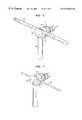
- FIG. 4is a perspective view of another embodiment of the device.
- FIG. 5is a cross-sectional view through the device of FIG. 4;
- FIGS. 6 and 7show the device of FIG. 4 holding respectively a pin and a wire in its gripping jaw
- FIG. 8is a cross-sectional view through the device according to a third embodiment of the invention.
- FIG. 9shows part of an external fixator for osteosynthesis and osteoplasty, in which a series of devices with clipping or gripping jaws of the present invention are shown as support pieces for positioning rods, pins and wires cooperating with a hoop.
- the positioning and locking devicegenerally denoted as 1 is made up of an upper jaw member 2 and a lower jaw member 3 having opened faces which are machined with assembly notches 4 to allow one to be positioned and pivoted against the other, leaving an opening 5 at the opposite end.
- a bushing or hollow shaft 6passes through the two jaws 2 , 3 at right angles, through the opposite end of the jaws with respect to the gripping jaw opening.
- bushing 6at its upper part 7 , has the shape of a cone frustum with slots 8 which start from this upper part 7 and run in the direction of the axis of the bushing to end about halfway down the length thereof.
- the lower part of bushing 6is threaded at 9 and is screwed into a nut 10 which clamps the two jaws 2 , 3 together.
- a spring in the form of a staple 11 a or bent wireis housed inside holes 12 each made in each one of the jaws 2 , 3 also on the opposite side to the opening of the gripping jaw.
- Upper jaw 2has a conical recess in its upper part and a cylindrical bore to accommodate bushing 6 and lower jaw 3 has a bore which has two opposed flat surfaces to play a part in holding bushing 6 in place especially against rotation, these flat surfaces not being depicted in the drawing.
- Bushing 6has a smaller diameter in its threaded lower part 9 and in its central part has two opposed flat surfaces, not shown in the drawing, which engage the flats on lower jaw 3 to prevent bushing 6 from rotating relative to the jaws and allow the nut to be locked.
- a rod 13may be inserted into bushing 6 and locked in position by the clamping action of the conical position of the upper part of bushing 6 which deforms inwardly as nut 10 is tightened pulling the bushing downwardly into the conical recess of upper jaw 2 . This causes upper part 7 of bushing 6 to deform inwardly in the area of slots 8 .
- This rod 13may remain fixed in a concrete assembly position so that one can adjust the relative positions of all the elements of the device prior to the final operation of tightening the assembly.
- FIG. 3shows in section the device of FIGS. 1 and 2 in which the elastic member is now an axial tension spring 11 b which, in its equilibrium portion, keeps the two jaws 2 , 3 assembled, allowing them to open during the clipping operation and holding the device locked until final tightening is performed using the nut 10 .
- the device 11consists of a tie bolt 20 , which at one of its ends has an upper jaw member 21 with balls 22 made of a material which is harder than the piece being clamped, these balls being made, for example, of ceramic or of a hard metal.
- a lower jaw member 31 with other balls 32 made of any material that is harder than the piece to be heldthe two jaw 21 , 31 creating an outer opening 51 with two cavities 52 , 53 ; a spiral spring 40 , a post 61 ending in a ring 62 at one of its ends.
- Ring 62may have teeth arranged therearound for engaging a toothed plate 71 .
- a nut in the form of a ribbed knob 81is threaded onto end 20 a of the bolt 20 .
- FIGS. 6 and 7show how the device 11 clips a pin 16 in its outer cavity 52 or a wire 17 in its inner cavity 53 .
- FIG. 8shows a third embodiment with a nut 82 as its connecting element.
- the part 75is a clamp with sets of gripping jaws with openings 85 , in which pins or wires can be clipped.
- the elastic elementmay be incorporated into the clamp and may be in the form of a thin piece of material located away from the openings and acting as a spring.
- the elastic elementmay be in the form of a narrow slit between adjacent jaw faces terminating in a small through bore 111 adjacent to the bottom of part 75 . As the bolt 82 is tightened in threaded bore 84 of post 161 , the narrow slit is closed with the thin metal of clamp 75 around bores 111 acting as a spring.
- bushing 6which passes through two jaws 2 , 3 is fitted into upper jaw 2 with the aid of the cone frustum shape of its upper part, which rests against the similarly shaped recess of the upper jaw.
- the rod 13is inserted into bushing 6 to finally be tightened using nut 10 .
- This nuthas a large head to make it easier to tighten by hand before being locked using any appropriate tool when the system is in place.
- Device 1 with rod 13 in placeis clipped via its outer opening 5 by lateral pressure onto a hoop or bar 91 and remains in this position by virtue of the action of the spring 11 a , 11 b . It goes without saying that any other form of opening is envisageable without departing from the scope of the present invention, to allow the device to be clipped onto any other part, not depicted.
- the two jaws 21 , 31use lateral pressure to clip a pin 16 or a wire 17 respectively in the outer cavity 52 or inner cavity 53 , against the face of the spring 40 .
- This springis a spiral spring which, pressing against the ribbed knob 81 , presses the lower jaw cheek 31 against the upper jaw cheek 21 ; the balls 22 , 32 positioned in an offset configuration, retain the wire so that this wire cannot escape from the gripping jaw.
- the ribbed knob 81presses the device-pin or device-wire assembly together and once the post 61 ,
- the ribbed knob 81has square head, but it goes without saying that any other shape of head may be used without departing from the scope of the present invention. As in the first embodiment and for the same reason, it has a large head to make it easier to initially tighten it by hand before finally locking it when the system is in place.
- FIG. 9depicts a hoop, bar or ring element 91 , without a complete circle being formed, which forms part of an external fixator 90 .
- the hoop elementhas a section with a web at the center of rectangular overall shape which serves as an element for connecting to two lateral reinforcements of cross section that is symmetrical with respect to an axis perpendicular to the web, allowing the support pieces to be clipped onto the inside or onto the outside of the hoop, as required.
- This figureshows three devices with clipping type gripping jaws according to the first embodiment 1 which are clipped, two to the inside of the hoop, and the third to its outside.
- devices 1are assembled with other devices 11 according to the second embodiment to show how the two embodiments 1, 11 according to the invention can collaborate with each other, post 61 of one of them becoming rod 13 of the other.
- Two pairs of devices 11support two transfixing wires which pass right through a bone (not shown), a third holds a pin 16 which would also be inserted into another part of the bone.
- the combination of these elements, the hoop with pins, wires, rods and devices with clipping gripping jawsmakes it possible to achieve relative positioning of items with respect to each other, tightening it by hand to thereafter lock it permanently while maintaining the relative positions between the various elements.
- the device of FIG. 9may also be assembled using a second hoop 91 .
Landscapes
- Health & Medical Sciences (AREA)
- Orthopedic Medicine & Surgery (AREA)
- Life Sciences & Earth Sciences (AREA)
- Surgery (AREA)
- Biomedical Technology (AREA)
- Engineering & Computer Science (AREA)
- Nuclear Medicine, Radiotherapy & Molecular Imaging (AREA)
- Heart & Thoracic Surgery (AREA)
- Medical Informatics (AREA)
- Molecular Biology (AREA)
- Animal Behavior & Ethology (AREA)
- General Health & Medical Sciences (AREA)
- Public Health (AREA)
- Veterinary Medicine (AREA)
- Surgical Instruments (AREA)
Abstract
Description
Claims (27)
Priority Applications (1)
| Application Number | Priority Date | Filing Date | Title |
|---|---|---|---|
| US10/006,941US20020042613A1 (en) | 1998-12-29 | 2001-12-04 | Positioning and locking device |
Applications Claiming Priority (2)
| Application Number | Priority Date | Filing Date | Title |
|---|---|---|---|
| CH2582/98 | 1998-12-29 | ||
| CH02582/98ACH693164A5 (en) | 1998-12-29 | 1998-12-29 | A locating and locking. |
Related Child Applications (1)
| Application Number | Title | Priority Date | Filing Date |
|---|---|---|---|
| US10/006,941ContinuationUS20020042613A1 (en) | 1998-12-29 | 2001-12-04 | Positioning and locking device |
Publications (1)
| Publication Number | Publication Date |
|---|---|
| US6342054B1true US6342054B1 (en) | 2002-01-29 |
Family
ID=4237039
Family Applications (2)
| Application Number | Title | Priority Date | Filing Date |
|---|---|---|---|
| US09/473,588Expired - LifetimeUS6342054B1 (en) | 1998-12-29 | 1999-12-28 | Positioning and locking device |
| US10/006,941AbandonedUS20020042613A1 (en) | 1998-12-29 | 2001-12-04 | Positioning and locking device |
Family Applications After (1)
| Application Number | Title | Priority Date | Filing Date |
|---|---|---|---|
| US10/006,941AbandonedUS20020042613A1 (en) | 1998-12-29 | 2001-12-04 | Positioning and locking device |
Country Status (6)
| Country | Link |
|---|---|
| US (2) | US6342054B1 (en) |
| EP (1) | EP1016380B1 (en) |
| JP (1) | JP3515032B2 (en) |
| CH (1) | CH693164A5 (en) |
| DE (2) | DE69921590T2 (en) |
| ES (1) | ES2232099T3 (en) |
Cited By (73)
| Publication number | Priority date | Publication date | Assignee | Title |
|---|---|---|---|---|
| US6533785B1 (en)* | 1998-05-07 | 2003-03-18 | Synthes (Usa) | Clamp for an external bone fixation device |
| US20030069580A1 (en)* | 2001-10-09 | 2003-04-10 | Langmaid Michael N. | Adjustable fixator |
| US20030109879A1 (en)* | 1994-12-05 | 2003-06-12 | Orsak James E. | External fixator for distal radius fractures |
| US20030149430A1 (en)* | 2002-02-04 | 2003-08-07 | Joseph Ferrante | Devices, systems, and methods for placing and positioning fixation elements in external fixation systems |
| US6613049B2 (en)* | 2000-02-02 | 2003-09-02 | Robert A. Winquist | Adjustable bone stabilizing frame system |
| US20030191468A1 (en)* | 2000-12-14 | 2003-10-09 | Synthes U.S.A. | Multipin clamp and rod attachment |
| US20040049273A1 (en)* | 1999-10-22 | 2004-03-11 | Archus Orthopedics, Inc. | Facet Arthroplasty devices and methods |
| US20040230201A1 (en)* | 2003-05-14 | 2004-11-18 | Archus Orthopedics Inc. | Prostheses, tools and methods for replacement of natural facet joints with artifical facet joint surfaces |
| US20040230304A1 (en)* | 2003-05-14 | 2004-11-18 | Archus Orthopedics Inc. | Prostheses, tools and methods for replacement of natural facet joints with artifical facet joint surfaces |
| US6896678B2 (en)* | 2000-10-05 | 2005-05-24 | The Jerome Group, Inc. | Ceramic-tipped skull pins |
| US20050119748A1 (en)* | 1999-10-22 | 2005-06-02 | Reiley Mark A. | Prostheses, systems and methods for replacement of natural facet joints with artificial facet joint surfaces |
| US20050131406A1 (en)* | 2003-12-15 | 2005-06-16 | Archus Orthopedics, Inc. | Polyaxial adjustment of facet joint prostheses |
| US20050143818A1 (en)* | 2003-05-14 | 2005-06-30 | Hansen Yuan | Prostheses, tools and methods for replacement of natural facet joints with artifical facet joint surfaces |
| WO2005085658A1 (en)* | 2004-03-10 | 2005-09-15 | Synthes Gmbh | Device for mutual positioning of longitudinal building components |
| WO2005099788A1 (en)* | 2004-04-19 | 2005-10-27 | Synthes Gmbh | Elastic element produced from radiolucent material for a medical device |
| US20050240266A1 (en)* | 2004-04-22 | 2005-10-27 | Kuiper Mark K | Crossbar spinal prosthesis having a modular design and related implantation methods |
| US20050267579A1 (en)* | 1999-10-22 | 2005-12-01 | Reiley Mark A | Implantable device for facet joint replacement |
| US20060039750A1 (en)* | 2004-08-20 | 2006-02-23 | Stryker Trauma S.A. | Clamping and articulation element |
| US20060041311A1 (en)* | 2004-08-18 | 2006-02-23 | Mcleer Thomas J | Devices and methods for treating facet joints |
| US20060052781A1 (en)* | 2004-08-20 | 2006-03-09 | Stryker Trauma S.A. | Clamp for multiple rod-shaped elements |
| US20060052785A1 (en)* | 2004-08-18 | 2006-03-09 | Augostino Teena M | Adjacent level facet arthroplasty devices, spine stabilization systems, and methods |
| US20060079895A1 (en)* | 2004-09-30 | 2006-04-13 | Mcleer Thomas J | Methods and devices for improved bonding of devices to bone |
| US20060085072A1 (en)* | 2004-04-22 | 2006-04-20 | Archus Orthopedics, Inc. | Implantable orthopedic device component selection instrument and methods |
| US20060085075A1 (en)* | 2004-10-04 | 2006-04-20 | Archus Orthopedics, Inc. | Polymeric joint complex and methods of use |
| US20060100707A1 (en)* | 2003-07-08 | 2006-05-11 | David Stinson | Prostheses, tools and methods for replacement of natural facet joints with artificial facet joint surfaces |
| US7048735B2 (en) | 2002-02-04 | 2006-05-23 | Smith & Nephew | External fixation system |
| US20060177263A1 (en)* | 2005-02-09 | 2006-08-10 | Stryker Trauma S.A. | External fixation clamp |
| US20060184180A1 (en)* | 2004-04-22 | 2006-08-17 | Augostino Teena M | Facet Joint Prosthesis Measurement and Implant Tools |
| US20060241598A1 (en)* | 2005-03-07 | 2006-10-26 | Khalili Farid B | Center locking cross-connector with eccentric cam rod engagement |
| US20060255521A1 (en)* | 2003-06-26 | 2006-11-16 | Peter Brunner | Clamp for external fixation |
| US20060287654A1 (en)* | 2006-08-11 | 2006-12-21 | Jeffrey Posnick | Implant securing device and method |
| US20070055234A1 (en)* | 2005-06-10 | 2007-03-08 | Mcgrath William M | External fixation system with provisional brace |
| US20070088358A1 (en)* | 2005-03-22 | 2007-04-19 | Hansen Yuan | Minimally Invasive Spine Restoration Systems, Devices, Methods and Kits |
| US20070093833A1 (en)* | 2004-05-03 | 2007-04-26 | Kuiper Mark K | Crossbar spinal prosthesis having a modular design and related implantation methods |
| US20070161983A1 (en)* | 2005-12-08 | 2007-07-12 | Ebi, L.P. | External fixation system |
| EP1820461A1 (en) | 2006-02-21 | 2007-08-22 | Stryker Trauma SA | Clamping and articulation element |
| US20070233256A1 (en)* | 2006-03-15 | 2007-10-04 | Ohrt John A | Facet and disc arthroplasty system and method |
| US20070255280A1 (en)* | 2003-01-10 | 2007-11-01 | Smith & Nephew, Inc. | External fixation apparatus and method |
| US20070276374A1 (en)* | 2005-03-02 | 2007-11-29 | Richard Broman | Arthroplasty revision system and method |
| EP1862135A1 (en) | 2006-05-29 | 2007-12-05 | Stryker Trauma SA | Clamping element and insert therefor |
| US20080082171A1 (en)* | 2004-04-22 | 2008-04-03 | Kuiper Mark K | Crossbar spinal prosthesis having a modular design and systems for treating spinal pathologies |
| US20080091200A1 (en)* | 2004-04-22 | 2008-04-17 | Kuiper Mark K | Crossbar spinal prosthesis having a modular design and related implantation methods |
| US20080097612A1 (en)* | 1999-10-22 | 2008-04-24 | Reiley Mark A | Facet Arthroplasty Devices and Methods |
| US20080103501A1 (en)* | 2006-08-11 | 2008-05-01 | Ralph Christopher R | Angled Washer Polyaxial Connection for Dynamic Spine Prosthesis |
| US20080177310A1 (en)* | 2000-10-20 | 2008-07-24 | Archus Orthopedics, Inc. | Facet arthroplasty devices and methods |
| US20080269810A1 (en)* | 2007-04-12 | 2008-10-30 | Texas Scottish Rite Hospital For Children | Orthopedic Fastener for Stabilization and Fixation |
| US20090036891A1 (en)* | 2005-08-09 | 2009-02-05 | Zimmer Technology, Inc. | Orthopaedic fixation clamp and method |
| US7758582B2 (en) | 2002-06-14 | 2010-07-20 | Smith & Nephew, Inc. | Device and methods for placing external fixation elements |
| US20110082458A1 (en)* | 2009-10-05 | 2011-04-07 | Stryker Trauma Sa | Dynamic External Fixator And Methods For Use |
| US8221461B2 (en) | 2004-10-25 | 2012-07-17 | Gmedelaware 2 Llc | Crossbar spinal prosthesis having a modular design and systems for treating spinal pathologies |
| US20130158551A1 (en)* | 2006-10-13 | 2013-06-20 | Stryker Trauma Sa | Prevention of re-use of a medical device |
| US8496686B2 (en) | 2005-03-22 | 2013-07-30 | Gmedelaware 2 Llc | Minimally invasive spine restoration systems, devices, methods and kits |
| US8523858B2 (en) | 2005-06-21 | 2013-09-03 | DePuy Synthes Products, LLC | Adjustable fixation clamp and method |
| CN103687558A (en)* | 2011-05-17 | 2014-03-26 | 捷迈有限公司 | External fixation clamping system using a trigger mechanism and stored spring energy |
| US8758343B2 (en) | 2005-04-27 | 2014-06-24 | DePuy Synthes Products, LLC | Bone fixation apparatus |
| US8834467B2 (en) | 2010-08-11 | 2014-09-16 | Stryker Trauma Sa | External fixator system |
| US8940020B2 (en) | 2012-04-06 | 2015-01-27 | DePuy Synthes Products, LLC | Rod connector |
| US8945128B2 (en) | 2010-08-11 | 2015-02-03 | Stryker Trauma Sa | External fixator system |
| US9101398B2 (en) | 2012-08-23 | 2015-08-11 | Stryker Trauma Sa | Bone transport external fixation frame |
| US9339305B2 (en) | 2011-09-19 | 2016-05-17 | DePuy Synthes Products, Inc. | Snap fit rod and fastener system |
| US9393045B2 (en) | 2013-03-15 | 2016-07-19 | Biomet Manufacturing, Llc. | Clamping assembly for external fixation system |
| US9539029B1 (en) | 2015-12-03 | 2017-01-10 | Globus Medical, Inc. | External fixator assembly |
| US9770272B2 (en) | 2012-12-12 | 2017-09-26 | Wright Medical Technology, Inc. | Orthopedic compression/distraction device |
| US9962188B2 (en) | 2013-10-29 | 2018-05-08 | Cardinal Health 247. Inc. | External fixation system and methods of use |
| US10010350B2 (en) | 2016-06-14 | 2018-07-03 | Stryker European Holdings I, Llc | Gear mechanisms for fixation frame struts |
| RU2663636C1 (en)* | 2017-09-25 | 2018-08-07 | федеральное государственное бюджетное учреждение "Российский научный центр "Восстановительная травматология и ортопедия" имени академика Г.А. Илизарова" Министерства здравоохранения Российской Федерации ФГБУ "РНЦ "ВТО" им. акад. Г.А. Илизарова" Минздрава России | Device for external fixation for children for transosseous osteosynthesis |
| RU2679585C2 (en)* | 2014-08-14 | 2019-02-11 | Аутомобили Ламборгини С.П.А. | Device for external orthopedic fixations |
| US10531896B2 (en) | 2015-08-10 | 2020-01-14 | Stryker European Holdings I, Llc | Distraction tube with wire clamp |
| US10874433B2 (en) | 2017-01-30 | 2020-12-29 | Stryker European Holdings I, Llc | Strut attachments for external fixation frame |
| CN113251206A (en)* | 2021-06-11 | 2021-08-13 | 江苏长隆石化装备有限公司 | Anchor ear reset mechanism of emergency release device ERC |
| US11141196B2 (en) | 2010-08-11 | 2021-10-12 | Stryker European Operations Holdings Llc | External fixator system |
| CN115068089A (en)* | 2022-06-30 | 2022-09-20 | 中国人民解放军联勤保障部队第九八九医院 | A wound outer frame composed of an arc-shaped snap ring rod clip and an arc-shaped snap ring rod clip |
| EP4427662A1 (en)* | 2023-03-06 | 2024-09-11 | FUJIFILM Corporation | Puncture device |
Families Citing this family (20)
| Publication number | Priority date | Publication date | Assignee | Title |
|---|---|---|---|---|
| GB2425958A (en)* | 2005-05-10 | 2006-11-15 | Veterinary Innovations Ltd | Collet type pin clamp for an external fracture fixator or distractor |
| US8029505B2 (en)* | 2005-08-25 | 2011-10-04 | Synthes Usa, Llc | External fixation system and method of use |
| ES2246744B1 (en)* | 2005-10-11 | 2006-12-01 | Implantvet, S.L. | ARTICULATION FOR MUTUAL SOLIDARIZATION BETWEEN BARS AND / OR NEEDLES IN AN EXTERNAL FIXING DEVICE FOR THE REDUCTION OF OSE FRACTURES. |
| US7585299B2 (en)* | 2006-02-17 | 2009-09-08 | Warsaw Orthopedic, Inc. | Dorsal adjusting spinal connector assembly |
| US7708736B2 (en)* | 2006-02-22 | 2010-05-04 | Extraortho, Inc. | Articulation apparatus for external fixation device |
| EP2197372B1 (en)* | 2007-09-27 | 2016-04-13 | Zimmer, Inc. | Clamping apparatus for external fixation and stabilization |
| US8187274B2 (en)* | 2008-06-30 | 2012-05-29 | Depuy Products, Inc. | External fixator |
| FR2948551B1 (en)* | 2009-07-31 | 2012-07-13 | Lars | MULTI-PURPOSE SURGICAL INSTRUMENT AND SURGICAL KIT |
| EP2319436B1 (en)* | 2009-11-06 | 2013-02-13 | ORTHOFIX S.r.l. | Clamp for external orthopaedic fixing device |
| EP2399532A1 (en)* | 2010-06-24 | 2011-12-28 | Franz Bentele | Jaw for an external fixator and articulation using such jaws |
| US9138260B2 (en) | 2010-07-01 | 2015-09-22 | Zimmer, Inc. | Multi-locking external fixation clamp |
| WO2012051312A1 (en) | 2010-10-12 | 2012-04-19 | Extraortho, Inc. | Single lock external fixation clamp arrangement |
| WO2012051255A1 (en) | 2010-10-12 | 2012-04-19 | Extraortho, Inc. | External fixation surgical clamp with swivel |
| US8728078B2 (en) | 2010-11-04 | 2014-05-20 | Zimmer, Inc. | Clamping assembly with links |
| WO2012078897A1 (en) | 2010-12-09 | 2012-06-14 | Extraortho, Inc. | Revolving lock for external fixation clamps |
| EP2648633B1 (en) | 2010-12-09 | 2016-05-18 | Zimmer, Inc. | External fixation clamp with cam driven jaw |
| US20130103090A1 (en)* | 2011-10-25 | 2013-04-25 | Warsaw Orthopedic, Inc. | Vertebral rod system and methods of use |
| EP2692303A1 (en)* | 2012-07-30 | 2014-02-05 | Swiss Ortho Trauma SA | Jaw for an external fixator and articulation using such jaws |
| FR3046725B1 (en)* | 2016-01-15 | 2021-09-10 | Gexfix Sa | ORTHOPEDIC FIXATION DEVICE |
| RU2661054C1 (en)* | 2017-03-10 | 2018-07-11 | Игорь Георгиевич Киселев | Polyfunctional monoblock for external designs of transosseous osteosynthesis in mammals (variants) |
Citations (7)
| Publication number | Priority date | Publication date | Assignee | Title |
|---|---|---|---|---|
| WO1988001152A1 (en) | 1986-08-22 | 1988-02-25 | Central Orthopaedics Ltd | A clamping device |
| US4784125A (en) | 1985-01-24 | 1988-11-15 | Jaquet Orthopedie, S. A. | Arcuate element and external fixation device containing same for osteosynthesis and osteoplasty |
| US5047029A (en)* | 1988-06-10 | 1991-09-10 | Synthes (U.S.A.) | Clamp and system for internal fixation |
| EP0704192A1 (en) | 1994-09-27 | 1996-04-03 | Charles James Newson | A bone fixing screw pin |
| WO1997035527A1 (en) | 1996-03-25 | 1997-10-02 | Synthes Ag Chur | Adjustable clamp for bone fixation element |
| EP0813845A1 (en) | 1996-06-20 | 1997-12-29 | Euros | Transverse connector for spinal implant support rods |
| US5752954A (en) | 1994-09-06 | 1998-05-19 | Howmedica International | External fixation device |
- 1998
- 1998-12-29CHCH02582/98Apatent/CH693164A5/ennot_activeIP Right Cessation
- 1999
- 1999-12-17ESES99811168Tpatent/ES2232099T3/ennot_activeExpired - Lifetime
- 1999-12-17EPEP99811168Apatent/EP1016380B1/ennot_activeExpired - Lifetime
- 1999-12-17DEDE69921590Tpatent/DE69921590T2/ennot_activeExpired - Lifetime
- 1999-12-23DEDE29922734Upatent/DE29922734U1/ennot_activeExpired - Lifetime
- 1999-12-27JPJP37171499Apatent/JP3515032B2/ennot_activeExpired - Lifetime
- 1999-12-28USUS09/473,588patent/US6342054B1/ennot_activeExpired - Lifetime
- 2001
- 2001-12-04USUS10/006,941patent/US20020042613A1/ennot_activeAbandoned
Patent Citations (10)
| Publication number | Priority date | Publication date | Assignee | Title |
|---|---|---|---|---|
| US4784125A (en) | 1985-01-24 | 1988-11-15 | Jaquet Orthopedie, S. A. | Arcuate element and external fixation device containing same for osteosynthesis and osteoplasty |
| US5095919A (en) | 1985-01-24 | 1992-03-17 | Jaquet Orthopedie S.A. | Arcuate element and external fixation device |
| WO1988001152A1 (en) | 1986-08-22 | 1988-02-25 | Central Orthopaedics Ltd | A clamping device |
| US5047029A (en)* | 1988-06-10 | 1991-09-10 | Synthes (U.S.A.) | Clamp and system for internal fixation |
| US5752954A (en) | 1994-09-06 | 1998-05-19 | Howmedica International | External fixation device |
| EP0700664B1 (en) | 1994-09-06 | 1999-09-29 | Jaquet Orthopedie S.A. | Articulation for components of an external fixator |
| EP0704192A1 (en) | 1994-09-27 | 1996-04-03 | Charles James Newson | A bone fixing screw pin |
| WO1997035527A1 (en) | 1996-03-25 | 1997-10-02 | Synthes Ag Chur | Adjustable clamp for bone fixation element |
| US5741252A (en) | 1996-03-25 | 1998-04-21 | Synthes U.S.A. | Adjustable clamp for bone fixation element |
| EP0813845A1 (en) | 1996-06-20 | 1997-12-29 | Euros | Transverse connector for spinal implant support rods |
Cited By (191)
| Publication number | Priority date | Publication date | Assignee | Title |
|---|---|---|---|---|
| US6793655B2 (en) | 1994-12-05 | 2004-09-21 | Smith & Nephew, Inc. | External fixator for distal radius fractures |
| US20030109879A1 (en)* | 1994-12-05 | 2003-06-12 | Orsak James E. | External fixator for distal radius fractures |
| US6533785B1 (en)* | 1998-05-07 | 2003-03-18 | Synthes (Usa) | Clamp for an external bone fixation device |
| US7608106B2 (en) | 1999-10-22 | 2009-10-27 | Archus Orthopedics, Inc. | Facet arthroplasty devices and methods |
| US20060009849A1 (en)* | 1999-10-22 | 2006-01-12 | Reiley Mark A | Facet arthroplasty devices and methods |
| US20080097612A1 (en)* | 1999-10-22 | 2008-04-24 | Reiley Mark A | Facet Arthroplasty Devices and Methods |
| US20080097613A1 (en)* | 1999-10-22 | 2008-04-24 | Reiley Mark A | Prostheses, Systems and Methods for Replacement of Natural Facet Joints With Artificial Facet Joint Surfaces |
| US20040049273A1 (en)* | 1999-10-22 | 2004-03-11 | Archus Orthopedics, Inc. | Facet Arthroplasty devices and methods |
| US20040049281A1 (en)* | 1999-10-22 | 2004-03-11 | Archus Orthopedics, Inc. | Facet arthroplasty devices and methods |
| US20080132951A1 (en)* | 1999-10-22 | 2008-06-05 | Reiley Mark A | Prostheses systems and methods for replacement of natural facet joints with artificial facet joint surfaces |
| US20080200953A1 (en)* | 1999-10-22 | 2008-08-21 | Reiley Mark A | Facet Joint Prostheses |
| US20080045954A1 (en)* | 1999-10-22 | 2008-02-21 | Reiley Mark A | Prostheses, systems and methods for replacement of natural facet joints with artificial facet joint surfaces |
| US7691145B2 (en) | 1999-10-22 | 2010-04-06 | Facet Solutions, Inc. | Prostheses, systems and methods for replacement of natural facet joints with artificial facet joint surfaces |
| US7087084B2 (en) | 1999-10-22 | 2006-08-08 | Archus Orthopedics, Inc. | Method for replacing a natural facet joint with a prosthesis having an artificial facet joint structure |
| US20050119748A1 (en)* | 1999-10-22 | 2005-06-02 | Reiley Mark A. | Prostheses, systems and methods for replacement of natural facet joints with artificial facet joint surfaces |
| US8066740B2 (en) | 1999-10-22 | 2011-11-29 | Gmedelaware 2 Llc | Facet joint prostheses |
| US20050137705A1 (en)* | 1999-10-22 | 2005-06-23 | Reiley Mark A. | Facet arthroplasty devices and methods |
| US20050137706A1 (en)* | 1999-10-22 | 2005-06-23 | Reiley Mark A. | Facet arthroplasty devices and methods |
| US8070811B2 (en) | 1999-10-22 | 2011-12-06 | Gmedelaware 2 Llc | Facet arthroplasty devices and methods |
| US20050149190A1 (en)* | 1999-10-22 | 2005-07-07 | Reiley Mark A. | Facet arthroplasty devices and methods |
| US20050234552A1 (en)* | 1999-10-22 | 2005-10-20 | Reiley Mark A | Facet arthroplasty devices and methods |
| US8092532B2 (en) | 1999-10-22 | 2012-01-10 | Gmedelaware 2 Llc | Facet arthroplasty devices and methods |
| US20060009847A1 (en)* | 1999-10-22 | 2006-01-12 | Reiley Mark A | Facet arthroplasty devices and methods |
| US20060009848A1 (en)* | 1999-10-22 | 2006-01-12 | Reiley Mark A | Facet arthroplasty device and methods |
| US20050251256A1 (en)* | 1999-10-22 | 2005-11-10 | Archus Orthopedics, Inc. | Facet arthroplasty devices and methods |
| US20050267579A1 (en)* | 1999-10-22 | 2005-12-01 | Reiley Mark A | Implantable device for facet joint replacement |
| US20050283238A1 (en)* | 1999-10-22 | 2005-12-22 | Reiley Mark A | Facet arthroplasty devices and methods |
| US6613049B2 (en)* | 2000-02-02 | 2003-09-02 | Robert A. Winquist | Adjustable bone stabilizing frame system |
| US6896678B2 (en)* | 2000-10-05 | 2005-05-24 | The Jerome Group, Inc. | Ceramic-tipped skull pins |
| US20080177310A1 (en)* | 2000-10-20 | 2008-07-24 | Archus Orthopedics, Inc. | Facet arthroplasty devices and methods |
| US20030191468A1 (en)* | 2000-12-14 | 2003-10-09 | Synthes U.S.A. | Multipin clamp and rod attachment |
| US8372073B2 (en)* | 2000-12-14 | 2013-02-12 | Sythes USA, LLC | Multi-pin clamp and rod attachment |
| US20030191467A1 (en)* | 2000-12-14 | 2003-10-09 | Hoffmann-Clair Mindy L. | Multipin clamp and rod attachment |
| US7041103B2 (en) | 2000-12-14 | 2006-05-09 | Synthes (Usa) | Multipin clamp and rod attachment |
| US20100160972A1 (en)* | 2000-12-14 | 2010-06-24 | Mindy Lynn Hoffman | Multi-Pin Clamp and Rod Attachmenton |
| US7699848B2 (en) | 2000-12-14 | 2010-04-20 | Synthes Usa, Llc | Multipin clamp and rod attachment |
| US20080097440A1 (en)* | 2001-09-25 | 2008-04-24 | Reiley Mark A | Prostheses, Systems and Methods for Replacement of Natural Facet Joints With Artificial Facet Joint Surfaces |
| US7261713B2 (en) | 2001-10-09 | 2007-08-28 | Synthes (Usa) | Adjustable fixator |
| US8382757B1 (en) | 2001-10-09 | 2013-02-26 | Synthes Usa, Llc | Adjustable fixator |
| US20030069580A1 (en)* | 2001-10-09 | 2003-04-10 | Langmaid Michael N. | Adjustable fixator |
| US20050119656A1 (en)* | 2002-02-04 | 2005-06-02 | Joseph Ferrante | External fixation system |
| US7887537B2 (en) | 2002-02-04 | 2011-02-15 | Smith & Nephew, Inc. | External fixation system |
| US7004943B2 (en) | 2002-02-04 | 2006-02-28 | Smith & Nephew, Inc. | Devices, systems, and methods for placing and positioning fixation elements in external fixation systems |
| US7048735B2 (en) | 2002-02-04 | 2006-05-23 | Smith & Nephew | External fixation system |
| US20030149430A1 (en)* | 2002-02-04 | 2003-08-07 | Joseph Ferrante | Devices, systems, and methods for placing and positioning fixation elements in external fixation systems |
| US7758582B2 (en) | 2002-06-14 | 2010-07-20 | Smith & Nephew, Inc. | Device and methods for placing external fixation elements |
| US20070255280A1 (en)* | 2003-01-10 | 2007-11-01 | Smith & Nephew, Inc. | External fixation apparatus and method |
| US8382755B2 (en) | 2003-01-10 | 2013-02-26 | Smith & Nephew, Inc. | External fixation apparatus and method |
| US7608074B2 (en) | 2003-01-10 | 2009-10-27 | Smith & Nephew, Inc. | External fixation apparatus and method |
| US20040230304A1 (en)* | 2003-05-14 | 2004-11-18 | Archus Orthopedics Inc. | Prostheses, tools and methods for replacement of natural facet joints with artifical facet joint surfaces |
| US20080275505A1 (en)* | 2003-05-14 | 2008-11-06 | Hansen Yuan | Prostheses, Tools and Methods for Replacement of Natural Facet Joints With Artificial Facet Joint Surfaces |
| US20040230201A1 (en)* | 2003-05-14 | 2004-11-18 | Archus Orthopedics Inc. | Prostheses, tools and methods for replacement of natural facet joints with artifical facet joint surfaces |
| US7608104B2 (en) | 2003-05-14 | 2009-10-27 | Archus Orthopedics, Inc. | Prostheses, tools and methods for replacement of natural facet joints with artifical facet joint surfaces |
| US20080125814A1 (en)* | 2003-05-14 | 2008-05-29 | Archus Orthopedics, Inc. | Prostheses, tools and methods for replacement of natural facet joints with artificial facet joint surfaces |
| US20070168029A1 (en)* | 2003-05-14 | 2007-07-19 | Yuan Hansen A | Prostheses, tools and methods for replacement of natural facet joints with artificial facet joint surfaces |
| US8409254B2 (en) | 2003-05-14 | 2013-04-02 | Gmedelaware 2 Llc | Prostheses, tools and methods for replacement of natural facet joints with artificial facet joint surfaces |
| US20060149375A1 (en)* | 2003-05-14 | 2006-07-06 | Yuan Hansen A | Prostheses, Tools And Methods For Replacement Of Natural Facet Joints With Artificial Facet Joint Surfaces |
| US20050143818A1 (en)* | 2003-05-14 | 2005-06-30 | Hansen Yuan | Prostheses, tools and methods for replacement of natural facet joints with artifical facet joint surfaces |
| US9198766B2 (en) | 2003-05-14 | 2015-12-01 | Gmedelaware 2 Llc | Prostheses, tools, and methods for replacement of natural facet joints with artificial facet joint surfaces |
| US20060255521A1 (en)* | 2003-06-26 | 2006-11-16 | Peter Brunner | Clamp for external fixation |
| US9492198B2 (en)* | 2003-06-26 | 2016-11-15 | DePuy Synthes Products, Inc. | Clamp for external fixation |
| US20060265070A1 (en)* | 2003-07-08 | 2006-11-23 | David Stinson | Prostheses and methods for replacement of natural facet joints with artificial facet joint surfaces |
| US20060100707A1 (en)* | 2003-07-08 | 2006-05-11 | David Stinson | Prostheses, tools and methods for replacement of natural facet joints with artificial facet joint surfaces |
| US8231655B2 (en) | 2003-07-08 | 2012-07-31 | Gmedelaware 2 Llc | Prostheses and methods for replacement of natural facet joints with artificial facet joint surfaces |
| US8523907B2 (en) | 2003-07-08 | 2013-09-03 | Gmedelaware 2 Llc | Prostheses, tools and methods for replacement of natural facet joints with artificial facet joint surfaces |
| US20080177332A1 (en)* | 2003-12-15 | 2008-07-24 | Archus Orthopedics, Inc. | Polyaxial adjustment of facet joint prostheses |
| US20050131406A1 (en)* | 2003-12-15 | 2005-06-16 | Archus Orthopedics, Inc. | Polyaxial adjustment of facet joint prostheses |
| US9056016B2 (en) | 2003-12-15 | 2015-06-16 | Gmedelaware 2 Llc | Polyaxial adjustment of facet joint prostheses |
| AU2004316649B2 (en)* | 2004-03-10 | 2008-03-20 | Synthes Gmbh | Device for mutual positioning of longitudinal building components |
| US20080247818A1 (en)* | 2004-03-10 | 2008-10-09 | Marc Oesch | Device For Mutual Positioning of Longitudinal Building Components |
| US10746214B2 (en) | 2004-03-10 | 2020-08-18 | DePuy Synthes Products, Inc. | Device for mutual positioning of longitudinal building components |
| WO2005085658A1 (en)* | 2004-03-10 | 2005-09-15 | Synthes Gmbh | Device for mutual positioning of longitudinal building components |
| US9089368B2 (en) | 2004-03-10 | 2015-07-28 | DePuy Synthes Products, Inc. | Device for mutual positioning of longitudinal building components |
| US20070293860A1 (en)* | 2004-04-19 | 2007-12-20 | Marc Oesch | Elastic Element Produced From Radiolucent Material For A Medical Device |
| CN100475278C (en)* | 2004-04-19 | 2009-04-08 | 斯恩蒂斯有限公司 | Elastic element, medical technical device and bone-fixing device |
| WO2005099788A1 (en)* | 2004-04-19 | 2005-10-27 | Synthes Gmbh | Elastic element produced from radiolucent material for a medical device |
| US20080091205A1 (en)* | 2004-04-22 | 2008-04-17 | Kuiper Mark K | Crossbar Spinal Prosthesis Having a Modular Design and Related Implantation Methods |
| US8425557B2 (en) | 2004-04-22 | 2013-04-23 | Gmedelaware 2 Llc | Crossbar spinal prosthesis having a modular design and related implantation methods |
| US20060085072A1 (en)* | 2004-04-22 | 2006-04-20 | Archus Orthopedics, Inc. | Implantable orthopedic device component selection instrument and methods |
| US7674293B2 (en) | 2004-04-22 | 2010-03-09 | Facet Solutions, Inc. | Crossbar spinal prosthesis having a modular design and related implantation methods |
| US20050240266A1 (en)* | 2004-04-22 | 2005-10-27 | Kuiper Mark K | Crossbar spinal prosthesis having a modular design and related implantation methods |
| US20060184180A1 (en)* | 2004-04-22 | 2006-08-17 | Augostino Teena M | Facet Joint Prosthesis Measurement and Implant Tools |
| US7406775B2 (en) | 2004-04-22 | 2008-08-05 | Archus Orthopedics, Inc. | Implantable orthopedic device component selection instrument and methods |
| US20080091204A1 (en)* | 2004-04-22 | 2008-04-17 | Kuiper Mark K | Crossbar spinal prosthesis having a modular design and related implantation methods |
| US8675930B2 (en) | 2004-04-22 | 2014-03-18 | Gmedelaware 2 Llc | Implantable orthopedic device component selection instrument and methods |
| US20080091200A1 (en)* | 2004-04-22 | 2008-04-17 | Kuiper Mark K | Crossbar spinal prosthesis having a modular design and related implantation methods |
| US20080082171A1 (en)* | 2004-04-22 | 2008-04-03 | Kuiper Mark K | Crossbar spinal prosthesis having a modular design and systems for treating spinal pathologies |
| US8187303B2 (en) | 2004-04-22 | 2012-05-29 | Gmedelaware 2 Llc | Anti-rotation fixation element for spinal prostheses |
| US20080292161A1 (en)* | 2004-04-22 | 2008-11-27 | Funk Michael J | Implantable orthopedic device component selection instrument and methods |
| US8491635B2 (en) | 2004-04-22 | 2013-07-23 | Gmedelaware 2 Llc | Crossbar spinal prosthesis having a modular design and related implantation methods |
| US8496687B2 (en) | 2004-04-22 | 2013-07-30 | Gmedelaware 2 Llc | Crossbar spinal prosthesis having a modular design and related implantation methods |
| US7290347B2 (en) | 2004-04-22 | 2007-11-06 | Archus Orthopedics, Inc. | Facet joint prosthesis measurement and implant tools |
| US20070093833A1 (en)* | 2004-05-03 | 2007-04-26 | Kuiper Mark K | Crossbar spinal prosthesis having a modular design and related implantation methods |
| US20060052785A1 (en)* | 2004-08-18 | 2006-03-09 | Augostino Teena M | Adjacent level facet arthroplasty devices, spine stabilization systems, and methods |
| US20060058791A1 (en)* | 2004-08-18 | 2006-03-16 | Richard Broman | Implantable spinal device revision system |
| US20060041311A1 (en)* | 2004-08-18 | 2006-02-23 | Mcleer Thomas J | Devices and methods for treating facet joints |
| US8398681B2 (en) | 2004-08-18 | 2013-03-19 | Gmedelaware 2 Llc | Adjacent level facet arthroplasty devices, spine stabilization systems, and methods |
| US20060052781A1 (en)* | 2004-08-20 | 2006-03-09 | Stryker Trauma S.A. | Clamp for multiple rod-shaped elements |
| US7241074B2 (en) | 2004-08-20 | 2007-07-10 | Stryker Trauma S.A. | Clamping and articulation element |
| US7618417B2 (en)* | 2004-08-20 | 2009-11-17 | Stryker Trauma S.A. | Clamp for multiple rod shaped elements |
| US20060039750A1 (en)* | 2004-08-20 | 2006-02-23 | Stryker Trauma S.A. | Clamping and articulation element |
| US20060079895A1 (en)* | 2004-09-30 | 2006-04-13 | Mcleer Thomas J | Methods and devices for improved bonding of devices to bone |
| US20090024219A1 (en)* | 2004-10-04 | 2009-01-22 | Archus Orthopedics, Inc. | Polymeric joint complex and methods of use |
| US20080140121A1 (en)* | 2004-10-04 | 2008-06-12 | Archus Orthopedics, Inc. | Polymeric joint complex and methods of use |
| US20080177309A1 (en)* | 2004-10-04 | 2008-07-24 | Archus Orthopedics, Inc. | Polymeric joint complex and methods of use |
| US20060085075A1 (en)* | 2004-10-04 | 2006-04-20 | Archus Orthopedics, Inc. | Polymeric joint complex and methods of use |
| US8221461B2 (en) | 2004-10-25 | 2012-07-17 | Gmedelaware 2 Llc | Crossbar spinal prosthesis having a modular design and systems for treating spinal pathologies |
| US20060177263A1 (en)* | 2005-02-09 | 2006-08-10 | Stryker Trauma S.A. | External fixation clamp |
| US7806623B2 (en) | 2005-02-09 | 2010-10-05 | Stryker Trauma S.A. | External fixation clamp |
| US20090148232A1 (en)* | 2005-02-09 | 2009-06-11 | Stryker Trauma Sa | External fixation clamp |
| US7491008B2 (en) | 2005-02-09 | 2009-02-17 | Stryker Trauma S.A. | External fixation clamp |
| US20070276374A1 (en)* | 2005-03-02 | 2007-11-29 | Richard Broman | Arthroplasty revision system and method |
| US7914556B2 (en) | 2005-03-02 | 2011-03-29 | Gmedelaware 2 Llc | Arthroplasty revision system and method |
| US20060241598A1 (en)* | 2005-03-07 | 2006-10-26 | Khalili Farid B | Center locking cross-connector with eccentric cam rod engagement |
| US20070088358A1 (en)* | 2005-03-22 | 2007-04-19 | Hansen Yuan | Minimally Invasive Spine Restoration Systems, Devices, Methods and Kits |
| US8496686B2 (en) | 2005-03-22 | 2013-07-30 | Gmedelaware 2 Llc | Minimally invasive spine restoration systems, devices, methods and kits |
| US8758343B2 (en) | 2005-04-27 | 2014-06-24 | DePuy Synthes Products, LLC | Bone fixation apparatus |
| US20070055234A1 (en)* | 2005-06-10 | 2007-03-08 | Mcgrath William M | External fixation system with provisional brace |
| US7306601B2 (en)* | 2005-06-10 | 2007-12-11 | Quantum Medical Concepts, Inc. | External fixation system with provisional brace |
| US8523858B2 (en) | 2005-06-21 | 2013-09-03 | DePuy Synthes Products, LLC | Adjustable fixation clamp and method |
| US9545266B2 (en) | 2005-06-21 | 2017-01-17 | DePuy Synthes Products, Inc. | Adjustable fixation clamp and method |
| US20090036891A1 (en)* | 2005-08-09 | 2009-02-05 | Zimmer Technology, Inc. | Orthopaedic fixation clamp and method |
| US20070161983A1 (en)* | 2005-12-08 | 2007-07-12 | Ebi, L.P. | External fixation system |
| US7422593B2 (en) | 2005-12-08 | 2008-09-09 | Ebi, L.P. | External fixation system |
| US8523923B2 (en)* | 2006-02-21 | 2013-09-03 | Stryker Trauma Sa | Clamping and articulation element |
| US8840653B2 (en) | 2006-02-21 | 2014-09-23 | Stryker Trauma Sa | Clamping and articulation element |
| US20070198012A1 (en)* | 2006-02-21 | 2007-08-23 | Stryker Trauma Sa | Clamping and articulation element |
| EP1820461A1 (en) | 2006-02-21 | 2007-08-22 | Stryker Trauma SA | Clamping and articulation element |
| AU2007200480B2 (en)* | 2006-02-21 | 2012-02-02 | Stryker European Operations Holdings Llc | Clamping and articulation element |
| US20070233256A1 (en)* | 2006-03-15 | 2007-10-04 | Ohrt John A | Facet and disc arthroplasty system and method |
| EP1862135A1 (en) | 2006-05-29 | 2007-12-05 | Stryker Trauma SA | Clamping element and insert therefor |
| US8444643B2 (en)* | 2006-05-29 | 2013-05-21 | Stryker Trauma Sa | Clamping element and insert therefor |
| US20090306661A1 (en)* | 2006-05-29 | 2009-12-10 | Stryker Trauma Sa | Clamping Element and Insert Therefor |
| US20080103501A1 (en)* | 2006-08-11 | 2008-05-01 | Ralph Christopher R | Angled Washer Polyaxial Connection for Dynamic Spine Prosthesis |
| US20060287654A1 (en)* | 2006-08-11 | 2006-12-21 | Jeffrey Posnick | Implant securing device and method |
| US8702755B2 (en) | 2006-08-11 | 2014-04-22 | Gmedelaware 2 Llc | Angled washer polyaxial connection for dynamic spine prosthesis |
| US20130158551A1 (en)* | 2006-10-13 | 2013-06-20 | Stryker Trauma Sa | Prevention of re-use of a medical device |
| US9549762B2 (en)* | 2006-10-13 | 2017-01-24 | Stryker European Holdings I, Llc | Prevention of re-use of a medical device |
| US20080269810A1 (en)* | 2007-04-12 | 2008-10-30 | Texas Scottish Rite Hospital For Children | Orthopedic Fastener for Stabilization and Fixation |
| US10603077B2 (en)* | 2007-04-12 | 2020-03-31 | Globus Medical, Inc. | Orthopedic fastener for stabilization and fixation |
| US20110082458A1 (en)* | 2009-10-05 | 2011-04-07 | Stryker Trauma Sa | Dynamic External Fixator And Methods For Use |
| US10149701B2 (en) | 2009-10-05 | 2018-12-11 | Stryker European Holdings I, Llc | Dynamic external fixator and methods for use |
| US8906020B2 (en) | 2009-10-05 | 2014-12-09 | Stryker Trauma Sa | Dynamic external fixator and methods for use |
| US8858555B2 (en) | 2009-10-05 | 2014-10-14 | Stryker Trauma Sa | Dynamic external fixator and methods for use |
| US9351763B2 (en) | 2009-10-05 | 2016-05-31 | Stryker European Holdings I, Llc | Dynamic external fixator and methods for use |
| US9730730B2 (en) | 2010-08-11 | 2017-08-15 | Stryker European Holdings I, Llc | External fixator system |
| US8945128B2 (en) | 2010-08-11 | 2015-02-03 | Stryker Trauma Sa | External fixator system |
| US12035944B2 (en) | 2010-08-11 | 2024-07-16 | Stryker European Operations Holdings Llc | External fixator system |
| US10285734B2 (en) | 2010-08-11 | 2019-05-14 | Stryker European Holdings I, Llc | External fixator system |
| US10080585B2 (en) | 2010-08-11 | 2018-09-25 | Stryker European Holdings I, Llc | External fixator system |
| US11141196B2 (en) | 2010-08-11 | 2021-10-12 | Stryker European Operations Holdings Llc | External fixator system |
| US9220533B2 (en) | 2010-08-11 | 2015-12-29 | Stryker Trauma Sa | External fixator system |
| US10376285B2 (en) | 2010-08-11 | 2019-08-13 | Stryker European Holdings I, Llc | External fixator system |
| US9717527B2 (en) | 2010-08-11 | 2017-08-01 | Stryker European Holdings I, Llc | External fixator system |
| US9839445B2 (en) | 2010-08-11 | 2017-12-12 | Stryker European Holdings I, Llc | External fixator system |
| US8834467B2 (en) | 2010-08-11 | 2014-09-16 | Stryker Trauma Sa | External fixator system |
| CN103687558B (en)* | 2011-05-17 | 2016-05-25 | 捷迈有限公司 | Use the external stability grasping system of trigger mechanism and spring energy-storage |
| US10702308B2 (en)* | 2011-05-17 | 2020-07-07 | Zimmer, Inc. | External fixation clamp using a trigger mechanism and stored spring energy |
| US9888943B2 (en) | 2011-05-17 | 2018-02-13 | Zimmer, Inc. | External fixation clamp using a trigger mechanism and stored spring energy |
| US20180103986A1 (en)* | 2011-05-17 | 2018-04-19 | Zimmer, Inc. | External fixation clamp using a trigger mechanism and stored spring energy |
| CN103687558A (en)* | 2011-05-17 | 2014-03-26 | 捷迈有限公司 | External fixation clamping system using a trigger mechanism and stored spring energy |
| US9339305B2 (en) | 2011-09-19 | 2016-05-17 | DePuy Synthes Products, Inc. | Snap fit rod and fastener system |
| US8940020B2 (en) | 2012-04-06 | 2015-01-27 | DePuy Synthes Products, LLC | Rod connector |
| US9101398B2 (en) | 2012-08-23 | 2015-08-11 | Stryker Trauma Sa | Bone transport external fixation frame |
| US11090086B2 (en) | 2012-08-23 | 2021-08-17 | Stryker European Operations Holdings Llc | Bone transport external fixation frame |
| US9820775B2 (en) | 2012-08-23 | 2017-11-21 | Styker European Holdings I, LLC | Bone transport external fixation frame |
| US11744616B2 (en) | 2012-08-23 | 2023-09-05 | Stryker European Operations Holdings Llc | Bone transport external fixation frame |
| US10405888B2 (en) | 2012-08-23 | 2019-09-10 | Stryker European Holdings I, Llc | Bone transport external fixation frame |
| US10631900B2 (en) | 2012-12-12 | 2020-04-28 | Wright Medical Technology, Inc. | Orthopedic compression/distraction device |
| US9770272B2 (en) | 2012-12-12 | 2017-09-26 | Wright Medical Technology, Inc. | Orthopedic compression/distraction device |
| US9827011B2 (en) | 2013-03-15 | 2017-11-28 | Biomet Manufacturing, Llc | Polyaxial pivot housing for external fixation system |
| US9393045B2 (en) | 2013-03-15 | 2016-07-19 | Biomet Manufacturing, Llc. | Clamping assembly for external fixation system |
| US10299830B2 (en) | 2013-03-15 | 2019-05-28 | Biomet Manufacturing, Llc | Clamping assembly for external fixation system |
| US9463045B2 (en) | 2013-03-15 | 2016-10-11 | Biomet Manufacturing, Llc | Polyaxial pivot housing for external fixation system |
| US9962188B2 (en) | 2013-10-29 | 2018-05-08 | Cardinal Health 247. Inc. | External fixation system and methods of use |
| RU2679585C2 (en)* | 2014-08-14 | 2019-02-11 | Аутомобили Ламборгини С.П.А. | Device for external orthopedic fixations |
| US10531896B2 (en) | 2015-08-10 | 2020-01-14 | Stryker European Holdings I, Llc | Distraction tube with wire clamp |
| US9872707B2 (en) | 2015-12-03 | 2018-01-23 | Globus Medical, Inc. | External fixator assembly |
| US10433874B2 (en) | 2015-12-03 | 2019-10-08 | Globus Medical, Inc. | External fixator assembly |
| US9539029B1 (en) | 2015-12-03 | 2017-01-10 | Globus Medical, Inc. | External fixator assembly |
| US10010350B2 (en) | 2016-06-14 | 2018-07-03 | Stryker European Holdings I, Llc | Gear mechanisms for fixation frame struts |
| US11504160B2 (en) | 2016-06-14 | 2022-11-22 | Stryker European Operations Holdings Llc | Gear mechanisms for fixation frame struts |
| US11974781B2 (en) | 2016-06-14 | 2024-05-07 | Stryker European Operations Holdings Llc | Gear mechanisms for fixation frame struts |
| US12201325B2 (en) | 2016-06-14 | 2025-01-21 | Stryker European Operations Holdings Llc | Gear mechanisms for fixation frame struts |
| US11723690B2 (en) | 2017-01-30 | 2023-08-15 | Stryker European Operations Holdings Llc | Strut attachments for external fixation frame |
| US10874433B2 (en) | 2017-01-30 | 2020-12-29 | Stryker European Holdings I, Llc | Strut attachments for external fixation frame |
| US12369948B2 (en) | 2017-01-30 | 2025-07-29 | Stryker European Operations Holdings Llc | Strut attachments for external fixation frame |
| RU2663636C1 (en)* | 2017-09-25 | 2018-08-07 | федеральное государственное бюджетное учреждение "Российский научный центр "Восстановительная травматология и ортопедия" имени академика Г.А. Илизарова" Министерства здравоохранения Российской Федерации ФГБУ "РНЦ "ВТО" им. акад. Г.А. Илизарова" Минздрава России | Device for external fixation for children for transosseous osteosynthesis |
| CN113251206A (en)* | 2021-06-11 | 2021-08-13 | 江苏长隆石化装备有限公司 | Anchor ear reset mechanism of emergency release device ERC |
| CN115068089A (en)* | 2022-06-30 | 2022-09-20 | 中国人民解放军联勤保障部队第九八九医院 | A wound outer frame composed of an arc-shaped snap ring rod clip and an arc-shaped snap ring rod clip |
| EP4427662A1 (en)* | 2023-03-06 | 2024-09-11 | FUJIFILM Corporation | Puncture device |
Also Published As
| Publication number | Publication date |
|---|---|
| DE69921590D1 (en) | 2004-12-09 |
| JP2000189437A (en) | 2000-07-11 |
| EP1016380B1 (en) | 2004-11-03 |
| US20020042613A1 (en) | 2002-04-11 |
| JP3515032B2 (en) | 2004-04-05 |
| CH693164A5 (en) | 2003-03-27 |
| DE29922734U1 (en) | 2000-03-30 |
| ES2232099T3 (en) | 2005-05-16 |
| EP1016380A1 (en) | 2000-07-05 |
| DE69921590T2 (en) | 2005-10-27 |
Similar Documents
| Publication | Publication Date | Title |
|---|---|---|
| US6342054B1 (en) | Positioning and locking device | |
| US8828060B2 (en) | Element with a shank and a holding element connected to it for connecting to a rod | |
| EP1009311B1 (en) | Surgical cable system | |
| US5752954A (en) | External fixation device | |
| US5122131A (en) | Orthopaedic device for mechanical coupling to a surgical rod | |
| US6682533B1 (en) | Surgical cable system and method | |
| EP1210914B1 (en) | Intervertebral fixing system used in treatments of the spinal column | |
| EP0425783A1 (en) | Pedicle screw clamp | |
| US8114077B2 (en) | Clamping pin | |
| EP2465454B1 (en) | Fixation clamp with thumbwheel | |
| US7931650B2 (en) | Adjustable bone stabilizing frame system | |
| TWI362252B (en) | ||
| US10966772B2 (en) | Cable fixation device, instruments, and methods | |
| US20100004694A1 (en) | Screw assembly | |
| US20120022601A1 (en) | Apparatus for bracing vertebrae | |
| JPH09313501A (en) | Surgical fixing device for bone fracture fixation | |
| JP2010536533A (en) | Loop rod spinal fixation device | |
| EP2019639A1 (en) | Locking device and method, for use in a bone stabilization system, employing a set screw member and deformable saddle member | |
| MX2007007307A (en) | Intervertebral stabilisation system. | |
| WO2016108970A1 (en) | Self-locking cable gripper | |
| HU209061B (en) | External fastener for medicating fractures of bone | |
| JP4451844B2 (en) | Device for fixing stringers and bone anchoring elements | |
| AU743254B2 (en) | Surgical cable system and method | |
| EP3322367A1 (en) | Cable fixation device, instruments, and methods | |
| KR20060059909A (en) | Elastic locking double chin for external fixture |
Legal Events
| Date | Code | Title | Description |
|---|---|---|---|
| AS | Assignment | Owner name:JAQUET ORTHOPEDIE, S.A., SWITZERLAND Free format text:ASSIGNMENT OF ASSIGNORS INTEREST;ASSIGNOR:MATA, JACQUES;REEL/FRAME:010679/0218 Effective date:20000302 | |
| AS | Assignment | Owner name:STRYKER TRAUMA SA, SWITZERLAND Free format text:CHANGE OF NAME;ASSIGNOR:JAQUET ORTHOPEDIE SA, A CORPORATION OF SWITZERLAND;REEL/FRAME:011719/0461 Effective date:19991206 | |
| STCF | Information on status: patent grant | Free format text:PATENTED CASE | |
| AS | Assignment | Owner name:STRYKER TRAUMA SA, SWITZERLAND Free format text:DISSOLUTION DOCUMENT;ASSIGNOR:STRYKER TRAUMA SA;REEL/FRAME:014990/0394 Effective date:20020628 Owner name:STRYKER TRAUMA SA, SWITZERLAND Free format text:MERGER;ASSIGNOR:STRYKER TRAUMA SA;REEL/FRAME:014990/0372 Effective date:20020625 | |
| FPAY | Fee payment | Year of fee payment:4 | |
| FPAY | Fee payment | Year of fee payment:8 | |
| FPAY | Fee payment | Year of fee payment:12 | |
| AS | Assignment | Owner name:STRYKER EUROPEAN HOLDINGS I, LLC, MICHIGAN Free format text:NUNC PRO TUNC ASSIGNMENT;ASSIGNOR:STRYKER EUROPEAN HOLDINGS V, LLC;REEL/FRAME:037153/0168 Effective date:20151008 Owner name:STRYKER EUROPEAN HOLDINGS V, LLC, MICHIGAN Free format text:NUNC PRO TUNC ASSIGNMENT;ASSIGNOR:STRYKER TRAUMA SA;REEL/FRAME:037153/0001 Effective date:20151008 | |
| AS | Assignment | Owner name:STRYKER EUROPEAN OPERATIONS HOLDINGS LLC, MICHIGAN Free format text:CHANGE OF NAME;ASSIGNOR:STRYKER EUROPEAN HOLDINGS III, LLC;REEL/FRAME:052860/0716 Effective date:20190226 Owner name:STRYKER EUROPEAN HOLDINGS III, LLC, DELAWARE Free format text:NUNC PRO TUNC ASSIGNMENT;ASSIGNOR:STRYKER EUROPEAN HOLDINGS I, LLC;REEL/FRAME:052861/0001 Effective date:20200519 |