US6341466B1 - Clip for securing an elongate member to a T-bar of a ceiling grid - Google Patents
Clip for securing an elongate member to a T-bar of a ceiling gridDownload PDFInfo
- Publication number
- US6341466B1 US6341466B1US09/487,960US48796000AUS6341466B1US 6341466 B1US6341466 B1US 6341466B1US 48796000 AUS48796000 AUS 48796000AUS 6341466 B1US6341466 B1US 6341466B1
- Authority
- US
- United States
- Prior art keywords
- clip
- bar
- recess
- elongate member
- extending
- Prior art date
- Legal status (The legal status is an assumption and is not a legal conclusion. Google has not performed a legal analysis and makes no representation as to the accuracy of the status listed.)
- Expired - Lifetime
Links
Images


Classifications
- E—FIXED CONSTRUCTIONS
- E04—BUILDING
- E04B—GENERAL BUILDING CONSTRUCTIONS; WALLS, e.g. PARTITIONS; ROOFS; FLOORS; CEILINGS; INSULATION OR OTHER PROTECTION OF BUILDINGS
- E04B9/00—Ceilings; Construction of ceilings, e.g. false ceilings; Ceiling construction with regard to insulation
- E04B9/06—Ceilings; Construction of ceilings, e.g. false ceilings; Ceiling construction with regard to insulation characterised by constructional features of the supporting construction, e.g. cross section or material of framework members
- E04B9/12—Connections between non-parallel members of the supporting construction
- E04B9/16—Connections between non-parallel members of the supporting construction the members lying in different planes
- E—FIXED CONSTRUCTIONS
- E04—BUILDING
- E04B—GENERAL BUILDING CONSTRUCTIONS; WALLS, e.g. PARTITIONS; ROOFS; FLOORS; CEILINGS; INSULATION OR OTHER PROTECTION OF BUILDINGS
- E04B9/00—Ceilings; Construction of ceilings, e.g. false ceilings; Ceiling construction with regard to insulation
- E04B9/006—Ceilings; Construction of ceilings, e.g. false ceilings; Ceiling construction with regard to insulation with means for hanging lighting fixtures or other appliances to the framework of the ceiling
- F—MECHANICAL ENGINEERING; LIGHTING; HEATING; WEAPONS; BLASTING
- F16—ENGINEERING ELEMENTS AND UNITS; GENERAL MEASURES FOR PRODUCING AND MAINTAINING EFFECTIVE FUNCTIONING OF MACHINES OR INSTALLATIONS; THERMAL INSULATION IN GENERAL
- F16B—DEVICES FOR FASTENING OR SECURING CONSTRUCTIONAL ELEMENTS OR MACHINE PARTS TOGETHER, e.g. NAILS, BOLTS, CIRCLIPS, CLAMPS, CLIPS OR WEDGES; JOINTS OR JOINTING
- F16B2/00—Friction-grip releasable fastenings
- F16B2/20—Clips, i.e. with gripping action effected solely by the inherent resistance to deformation of the material of the fastening
- F16B2/22—Clips, i.e. with gripping action effected solely by the inherent resistance to deformation of the material of the fastening of resilient material, e.g. rubbery material
- F16B2/24—Clips, i.e. with gripping action effected solely by the inherent resistance to deformation of the material of the fastening of resilient material, e.g. rubbery material of metal
- F16B2/241—Clips, i.e. with gripping action effected solely by the inherent resistance to deformation of the material of the fastening of resilient material, e.g. rubbery material of metal of sheet metal
- F—MECHANICAL ENGINEERING; LIGHTING; HEATING; WEAPONS; BLASTING
- F16—ENGINEERING ELEMENTS AND UNITS; GENERAL MEASURES FOR PRODUCING AND MAINTAINING EFFECTIVE FUNCTIONING OF MACHINES OR INSTALLATIONS; THERMAL INSULATION IN GENERAL
- F16B—DEVICES FOR FASTENING OR SECURING CONSTRUCTIONAL ELEMENTS OR MACHINE PARTS TOGETHER, e.g. NAILS, BOLTS, CIRCLIPS, CLAMPS, CLIPS OR WEDGES; JOINTS OR JOINTING
- F16B7/00—Connections of rods or tubes, e.g. of non-circular section, mutually, including resilient connections
- F16B7/04—Clamping or clipping connections
- F16B7/044—Clamping or clipping connections for rods or tubes being in angled relationship
- Y—GENERAL TAGGING OF NEW TECHNOLOGICAL DEVELOPMENTS; GENERAL TAGGING OF CROSS-SECTIONAL TECHNOLOGIES SPANNING OVER SEVERAL SECTIONS OF THE IPC; TECHNICAL SUBJECTS COVERED BY FORMER USPC CROSS-REFERENCE ART COLLECTIONS [XRACs] AND DIGESTS
- Y10—TECHNICAL SUBJECTS COVERED BY FORMER USPC
- Y10S—TECHNICAL SUBJECTS COVERED BY FORMER USPC CROSS-REFERENCE ART COLLECTIONS [XRACs] AND DIGESTS
- Y10S248/00—Supports
- Y10S248/906—Electrical outlet box support
- Y—GENERAL TAGGING OF NEW TECHNOLOGICAL DEVELOPMENTS; GENERAL TAGGING OF CROSS-SECTIONAL TECHNOLOGIES SPANNING OVER SEVERAL SECTIONS OF THE IPC; TECHNICAL SUBJECTS COVERED BY FORMER USPC CROSS-REFERENCE ART COLLECTIONS [XRACs] AND DIGESTS
- Y10—TECHNICAL SUBJECTS COVERED BY FORMER USPC
- Y10T—TECHNICAL SUBJECTS COVERED BY FORMER US CLASSIFICATION
- Y10T24/00—Buckles, buttons, clasps, etc.
- Y10T24/30—Trim molding fastener
- Y10T24/303—Trim molding fastener having laterally extending biasing appendage
- Y—GENERAL TAGGING OF NEW TECHNOLOGICAL DEVELOPMENTS; GENERAL TAGGING OF CROSS-SECTIONAL TECHNOLOGIES SPANNING OVER SEVERAL SECTIONS OF THE IPC; TECHNICAL SUBJECTS COVERED BY FORMER USPC CROSS-REFERENCE ART COLLECTIONS [XRACs] AND DIGESTS
- Y10—TECHNICAL SUBJECTS COVERED BY FORMER USPC
- Y10T—TECHNICAL SUBJECTS COVERED BY FORMER US CLASSIFICATION
- Y10T24/00—Buckles, buttons, clasps, etc.
- Y10T24/30—Trim molding fastener
- Y10T24/304—Resilient metal type
- Y10T24/307—Sheet metal formed
- Y—GENERAL TAGGING OF NEW TECHNOLOGICAL DEVELOPMENTS; GENERAL TAGGING OF CROSS-SECTIONAL TECHNOLOGIES SPANNING OVER SEVERAL SECTIONS OF THE IPC; TECHNICAL SUBJECTS COVERED BY FORMER USPC CROSS-REFERENCE ART COLLECTIONS [XRACs] AND DIGESTS
- Y10—TECHNICAL SUBJECTS COVERED BY FORMER USPC
- Y10T—TECHNICAL SUBJECTS COVERED BY FORMER US CLASSIFICATION
- Y10T24/00—Buckles, buttons, clasps, etc.
- Y10T24/44—Clasp, clip, support-clamp, or required component thereof
- Y10T24/44641—Clasp, clip, support-clamp, or required component thereof having gripping member formed from, biased by, or mounted on resilient member
- Y10T24/44769—Opposed engaging faces on gripping member formed from single piece of resilient material
- Y10T24/44923—Clasp, clip, or support-clamp cut or shaped from a single sheet of resilient, uniformly thick, planar material
- Y—GENERAL TAGGING OF NEW TECHNOLOGICAL DEVELOPMENTS; GENERAL TAGGING OF CROSS-SECTIONAL TECHNOLOGIES SPANNING OVER SEVERAL SECTIONS OF THE IPC; TECHNICAL SUBJECTS COVERED BY FORMER USPC CROSS-REFERENCE ART COLLECTIONS [XRACs] AND DIGESTS
- Y10—TECHNICAL SUBJECTS COVERED BY FORMER USPC
- Y10T—TECHNICAL SUBJECTS COVERED BY FORMER US CLASSIFICATION
- Y10T403/00—Joints and connections
- Y10T403/49—Member deformed in situ
- Y10T403/4941—Deformation occurs simultaneously with action of separate, diverse function, joint component
- Y—GENERAL TAGGING OF NEW TECHNOLOGICAL DEVELOPMENTS; GENERAL TAGGING OF CROSS-SECTIONAL TECHNOLOGIES SPANNING OVER SEVERAL SECTIONS OF THE IPC; TECHNICAL SUBJECTS COVERED BY FORMER USPC CROSS-REFERENCE ART COLLECTIONS [XRACs] AND DIGESTS
- Y10—TECHNICAL SUBJECTS COVERED BY FORMER USPC
- Y10T—TECHNICAL SUBJECTS COVERED BY FORMER US CLASSIFICATION
- Y10T403/00—Joints and connections
- Y10T403/60—Biased catch or latch
- Y10T403/602—Biased catch or latch by separate spring
Definitions
- This inventionrelates generally to devices for mounting elongate members, such as lather's channel, on T-bars of a ceiling grid.
- Lights, speaker boxes, fire alarm boxes and other fixturesare commonly mounted on the T-bars of a ceiling grid. Many of these fixtures are mounted on elongate members, typically lather's channels, which span parallel T-bars of the grid. For example, light fixtures are typically mounted on a pair of spaced apart, generally parallel, lather's channels which are then placed on the ceiling grid with the ends of the channels positioned on parallel T-bars of the grid.
- Various deviceshave been used to secure the lather's channels to the T-bars. The most common method is to use clips of the type which must first be installed on the T-bars at locations estimated to correspond to the spacing between the two channels. The clips have upwardly opening slots or recesses which then receive the channels.
- an improved clip for securing an elongate member to a T-bar of a ceiling gridthe provision of such a clip which can be applied after the elongate member has been positioned on the T-bar; the provision of such a clip which can be used to secure various types of members, including lather's channels and conduit; the provision of such a clip which is easy to install without the use of special tools; the provision of such a clip which is strong and capable of securely holding a member in place against both lateral and longitudinal movement relative to the T-bar; and the provision of such a clip which can be quickly installed, thereby reducing labor time.
- a clip of the inventionis used for securing an elongate member to a horizontal T-bar of a ceiling grid.
- the T-barhas a base, a stem extending up from the base, and a head at the upper end of the stem.
- the elongate memberis adapted to be secured to the T-bar in a generally horizontal position extending at an angle to the T-bar and resting on the head of the T-bar.
- the clipcomprises a body having a downwardly opening recess therein for permitting the body to be placed over the elongate member without removing the member from the T-bar.
- the clipis placed in a seated position in which the member is received in the recess. Clasps depending from the body are configured so that as the body is moved toward its seated position, the clasps assume positions on opposite sides of the stem of the T-bar for clasping the T-bar and securing the clip to the T-bar.
- the clipincorporates a device which is engageable with the elongate member when the body is in the seated position.
- the deviceholds the elongate member against movement of the member in a longitudinal direction with respect to the member.
- the present inventionfurther involves a method of securing an elongate member to a horizontal T-bar of a ceiling grid.
- the methodcomprises the steps of placing the elongate member on the head of the T-bar, and securing the elongate member to the T-bar in a position in which the member extends at an angle relative to the T-bar by using a clip having a body having a downwardly opening recess therein and clasps depending from the body.
- the bodyis placed over the elongate fixture member, without removing the member from the framing, in a seated position in which the member is received in the recess and the clasps extend down on opposite sides of the stem of the T-bar and engage opposite faces of the stem to secure the clip to the T-bar.
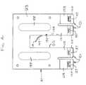
- FIG. 1is a perspective view of a light fixture assembly secured to a ceiling grid by several clips of the present invention
- FIG. 2is an enlarged portion of FIG. 1 showing one of the clips holding a lather's channel on a T-bar of the ceiling grid;
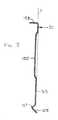
- FIG. 3is a front elevational view of the clip of FIG. 2;
- FIG. 4is a rear elevational view of the clip of FIG. 2;
- FIG. 5is a left side elevational view of the clip shown in FIG. 3;
- FIG. 6is a sectional view taken in the plane of 6 — 6 in FIG. 3;
- FIG. 7is a sectional view taken in the plane of 7 — 7 in FIG. 3;
- FIG. 8is a front view of the clip holding a lather's channel on the T-bar
- FIG. 9is a rear view of the clip holding a lather's channel on the T-bar
- FIG. 10is a left side elevational view of the clip and T-bar shown in FIG. 8;
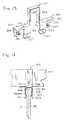
- FIG. 11is a perspective view of a clip with a recess shaped for receiving a tubular member of circular cross section;
- FIG. 12is a side elevational view of the clip of FIG. 11 used to secure a tubular member to a T-bar;
- FIG. 13is a front perspective view of a clip with a recess shaped for receiving a tubular member of rectangular cross section;
- FIG. 14is a side elevational view of the clip of FIG. 13 used to secure a tubular member to a T-bar.
- a clip of the present inventionis indicated in its entirety by the reference numeral 51 .
- the light fixture assembly 53includes a lamp housing 61 , a housing bracket 63 , and two side clamps 65 for mounting the assembly on a pair of elongate members 67 .
- These membersare illustrated as being conventional lather's channels 67 .
- each channel 67comprises a pair of horizontal flanges 71 connected by a vertical web 73 .
- the channel 67is typically formed from sheet metal having a thickness of between 0.030 and 0.090 inches.
- a lather's channel 67typically has a nominal height (i.e., web width) of 1.5 inches and a width (i.e., flange depth) of 0.50-0.625 inches. It will be understood that elongate members other than lather's channels can be used without departing from the scope of this invention.
- the aforementioned grid 55comprises a plurality of framing members, typically in the form of T-bars 81 .
- Each T-bar 81is typically an elongate member formed from metal and shaped like an inverted “T” in cross section.
- the “T” cross-sectional shapeadds rigidity and functionality to the T-bar 81 .
- the T-bar 81has a base 83 constituted by a horizontal flange, a vertical stem 87 extending up from the base 83 , and a head 89 in the form of a hollow bulb at the upper end of the stem.
- T-bars 81are arranged orthogonally to form the grid 55 that acts as a framework for a drop ceiling (not shown).
- Opaque panels situated within the spaces of the T-bar 81 frameworkcomplete the drop ceiling.
- Drop ceilings arranged horizontally, a distance below a true ceilingcreate a space between the drop ceiling and the true ceiling where electrical, plumbing, climate control, and other equipment may be hidden from view.
- Some articles, such as lights, speaker boxes, fire alarm boxes, and other fixturesare preferably not fully hidden from view.
- Those fixturestypically attach to the T-bar 81 framework above the drop ceiling, having only a lower portion of the fixture extending down and through a hole cut in the panel. Therefore, drop ceilings allow fixtures to be selectively revealed or hidden from view.
- the workermust often reposition the conventional clips to a proper location, which requires that the worker either put the fixture assembly down before repositioning the clips or reposition the clips while supporting the weight of the fixture and holding the fixture it its desired location. In either case, the procedure is awkward and inefficient.
- the clip 51 of the present inventionsolves the aforementioned problem because it allows the fixture 53 and lather's channels 67 to be placed as a complete assembly on top of the T-bar 81 ceiling grid 55 and then secured in position without moving the assembly. After the assembly has been properly positioned, the worker installing the fixture 53 simply pushes the clips 51 down over the lather's channels 67 and into engagement with the T-bar 81 , thereby holding the assembly in position. The fixture 53 need not be put down or held in place while adjusting the clips 51 since clip installation occurs after final positioning of the fixture. Thus, the clips 51 increase the efficiency of installation, removing the awkward step of either putting the fixture in a different location while the clips are repositioned or holding the fixture 53 near the T-bars 81 while attempting to adjust the clips during installation.
- a clip 51 of the present inventionhas a generally planar body 93 formed from heat treated sheet metal, preferably sheet steel having a thickness of 0.030-0.034 inches.
- the body 93has a downwardly opening recess 95 , permitting the body to be placed over the lather's channel 67 with the channel received in the recess.
- the preferred recess 95is a rectangular notch, having a width W (FIG. 3) of greater than 0.625 in. for receiving 0.50 in. to 0.625 in. wide lather's channel 67 and a height H (FIG. 3) of greater than 1.5 in. for receiving 1.5 in. tall lather's channel.
- the clip 51is installed over the lather's channel 67 while the channel rests in a seated position on the T-bars 81 , without removing the channel from the T-bars.
- a plurality of claspsdepend from the body 93 of the clip 51 so that as the body is pushed down over the lather's channel 67 toward the seated position shown in FIG. 8, the clasps assume positions on opposite sides of the head 89 and stem 87 of the T-bar 81 for clasping the T-bar and securing the clip to the T-bar.
- FIGS. 1-10A plurality of clasps, generally indicated at 101 , depend from the body 93 of the clip 51 so that as the body is pushed down over the lather's channel 67 toward the seated position shown in FIG. 8, the clasps assume positions on opposite sides of the head 89 and stem 87 of the T-bar 81 for clasping the T-bar and securing the clip to the T-bar.
- each clip 51has four clasps 101 comprising an outer pair of spring legs designated 103 and 105 which extend down from the body 93 adjacent opposite sides of the body for engagement with a first face 107 of the stem 87 of the T-bar 81 , and an inner pair of spring legs designated 113 and 115 which extend down from the body between the outer spring legs immediately adjacent opposite sides of the recess 95 for engagement with a second face 117 of the stem 87 opposite the first face.
- the outer legs 103 , 105are bent to have horizontal shoulders 121 adjacent their upper ends (FIG. 10 ). When fully seated on the T-bar 81 , these shoulders 121 contact the top of the head 89 of the T-bar, inhibiting further downward movement of the clip 51 .
- the lower ends of the outer 103 , 105 and inner spring legs 113 , 115have feet 125 angled laterally outwardly away from the central plane P of the body to guide the spring legs 103 , 105 , 113 , 115 over the head 89 of the T-bar 81 .
- the clasps 101function so that as the body 93 moves toward its seated position against the top of the T-bar 81 , the spring legs 103 , 105 , 113 , 115 assume positions on opposite sides of the stem 87 of the T-bar 81 for clasping the T-bar and securing the clip 51 to the T-bar.
- the spring legsimpart a clamping force upon the T-bar 81 , thereby facilitating retention of the clip 51 on the T-bar.
- the spring legs 103 , 105 , 113 , 115have tabs 127 lanced therefrom that extend upwardly and inwardly from the legs for engagement with the first and second stem faces 107 , 117 .
- tabs 127bite into the stem 87 of the T-bar 81 , further securing the clip 51 to the T-bar. Once the clip 51 is fully seated on the T-bar 81 , the tabs 127 engage the stem 87 below the head 89 , inhibiting the clip from moving upward as the tabs will bite into the head if an upward force is exerted upon the clip.
- the collective clamping force exerted by the spring legs 103 , 105 , 113 , 115 and the tabs 127ensures that the clips 51 do not move with respect to the T-bar 81 or become inadvertently dislodged.
- the body 93further has a device comprising a spring finger 131 for holding the lather's channel 67 against movement of the channel within the clip 51 in a longitudinal direction with respect to the channel.
- the spring finger 131is integrally formed from the body 93 of the clip 51 , being arranged at a right angle to the body and connected at its lower end to the body along a vertical bend line 133 near an edge of the recess 95 .
- a stiffening rib 135 located near the center of the bend 133reinforces the bend.
- the spring finger 131has a free upper end 141 formed with at least one tooth 143 (two are shown in the preferred embodiment) thereon adapted for biting into the vertical web 73 of the lather's channel 67 .
- the spring finger 131has a first transverse bend line 145 spaced in from its upper end 141 , and a second transverse bend line 147 spaced in from the first bend line.
- the upper end portion 141 of the spring finger 131slopes inwardly into the recess 95 from these bend lines 145 , 147 .
- the preferred angle of the spring finger 131 above the first bend line 145is about 60° off vertical as the angle of the spring finger above the second bend line 147 and below the first bend line is about 30° off vertical, the finger thus creating an interference within the projected area of the recess.
- the lather's channelmoves the spring finger 131 outward from a relaxed condition (FIGS. 3-4) to a deflected condition (FIGS. 8-9) in which it exerts a spring force against the channel 67 to hold the channel against the opposite edge of the recess 95 , thereby inhibiting longitudinal movement of the lather's channel.
- the body 93 of the clip 51has a flange 153 along an upper edge thereof extending generally at a right angle to the body.
- the flange 153extends the full width of the clip 51 , providing a horizontal surface for pushing the body 93 down to its seated position over the lather's channel 67 and T-bar 81 .
- the flange 153 surfaceis of an adequate area to allow the clip 51 to be easily pressed down onto the T-bar 81 manually.
- the clip 51 body 93has at least two vertical, oblong stiffening ribs 155 on opposite sides of the recess 95 .
- the stiffening ribs 155strengthen the clip 51 , ensuring that the clip retains its shape, without deformation, during installation and use.
- the ribs 155may be of any number and shape without departing from the scope of the invention.
- FIGS. 11 and 12show a second clip of the present invention, generally designated 201 .
- the body 293 of the clip 201defines a recess 295 which is preferably hemispherical at its upper end 231 for receiving a tubular member of circular cross section 207 .
- the shape of the recess 295closely matches the cross sectional shape of the tubular member 207 , creating a close fit between the tubular member and the clip 201 .
- the close fit of the clip 201helps hold the tubular member 207 in place, minimizing movement of the tubular member within the recess 295 .
- the shape and size of the recess 295may vary to accommodate differently-shaped tubular members without departing from the scope of the invention.
- the clip 201is attachable to a T-bar 81 in a manner similar to the previous embodiment.
- a pair of shoulders 217extend laterally outwardly from the lower lateral edges of the recess 295 , providing a horizontal surface 219 engageable with the head 89 of the T-bar 81 and a bearing surface 221 for pressing the clip 201 over the head of the T-bar.
- FIGS. 13 and 14show a third clip of the present invention, generally designated 301 .
- the body 393 of the clip 301defines a recess 395 which is preferably rectangular for receiving a member of rectangular cross section 307 .
- the shape of the recess 395closely matches the cross sectional shape of the rectangular member 307 , creating a close fit between the member and the clip 301 .
- the close fit of the clip 301helps hold the rectangular member 307 in place, minimizing movement of the member within the recess 395 .
- the clip 301is attachable to a T-bar 81 in a manner similar to the first embodiment.
- a pair of shoulders 317extend laterally outwardly from the lower lateral edges of the recess 395 , providing a horizontal surface 319 engageable with the head 89 of the T-bar 81 and a bearing surface 321 for pressing the clip 301 over the head of the T-bar.
- the clips 51 , 201 , 301 described abovecan be used to conveniently secure an elongate fixture member to a T-bar 81 of a ceiling grid 55 .
- four clips 51can be used to secure the fixture assembly 53 of FIG. 1 to parallel T-bars 81 of a ceiling grid 55 .
- a workerplaces and properly positions multiple lather's channels 67 supporting a fixture 53 across multiple T-bars 81 .
- the workersecures the lather's channel 67 to the T-bar 81 using clips 51 of the present invention.
- the lather's channels 67preferably lie at right angles to the T-bars 81 , although other angles are contemplated as part of the disclosed invention.
- the workersecures the lather's channel 67 to the T-bar 81 by placing the body 93 of each clip 51 over the channel without removing the channel from the T-bar.
- the clip 51is pushed down to its seated position in which the lather's channel 67 is received in recess 95 and the clasps 101 extend down on opposite sides of the T-bar 81 for engaging and securing to opposite sides of the stem 87 .
- multiple clips 51secure multiple pieces of lather's channel 67 to multiple T-bars 81 .
Landscapes
- Engineering & Computer Science (AREA)
- General Engineering & Computer Science (AREA)
- Architecture (AREA)
- Mechanical Engineering (AREA)
- Physics & Mathematics (AREA)
- Electromagnetism (AREA)
- Civil Engineering (AREA)
- Structural Engineering (AREA)
- Clamps And Clips (AREA)
Abstract
Description
Claims (16)
Priority Applications (1)
| Application Number | Priority Date | Filing Date | Title |
|---|---|---|---|
| US09/487,960US6341466B1 (en) | 2000-01-19 | 2000-01-19 | Clip for securing an elongate member to a T-bar of a ceiling grid |
Applications Claiming Priority (1)
| Application Number | Priority Date | Filing Date | Title |
|---|---|---|---|
| US09/487,960US6341466B1 (en) | 2000-01-19 | 2000-01-19 | Clip for securing an elongate member to a T-bar of a ceiling grid |
Publications (1)
| Publication Number | Publication Date |
|---|---|
| US6341466B1true US6341466B1 (en) | 2002-01-29 |
Family
ID=23937805
Family Applications (1)
| Application Number | Title | Priority Date | Filing Date |
|---|---|---|---|
| US09/487,960Expired - LifetimeUS6341466B1 (en) | 2000-01-19 | 2000-01-19 | Clip for securing an elongate member to a T-bar of a ceiling grid |
Country Status (1)
| Country | Link |
|---|---|
| US (1) | US6341466B1 (en) |
Cited By (84)
| Publication number | Priority date | Publication date | Assignee | Title |
|---|---|---|---|---|
| US6523313B2 (en)* | 2001-03-06 | 2003-02-25 | Worthington Armstrong Venture | Main beam connection |
| US20030095135A1 (en)* | 2001-05-02 | 2003-05-22 | Kaasila Sampo J. | Methods, systems, and programming for computer display of images, text, and/or digital content |
| US6591540B1 (en)* | 2001-04-09 | 2003-07-15 | Tony Chargois | Support harness adaptor for fishing reel and rod |
| US20030217521A1 (en)* | 2002-05-24 | 2003-11-27 | Richard B. Richardson | Adjustable anchoring system for a wall |
| US20030226870A1 (en)* | 2002-06-06 | 2003-12-11 | Oetlinger Frank E. | Connection device for interconnecting a grid element to lower frame assembly of a blanking tool |
| US20040050226A1 (en)* | 2002-09-18 | 2004-03-18 | Oetlinger Frank E. | Locator bracket for the lower frame assembly of a blanking tool |
| US6729587B1 (en) | 2002-05-31 | 2004-05-04 | Bellsouth Intellectual Property Corporation | Communication cable support for drop ceiling |
| US6729083B1 (en)* | 2003-03-12 | 2004-05-04 | Jaco Arf, Llc | Adjustable roof support frame |
| US20040177976A1 (en)* | 1999-01-08 | 2004-09-16 | Pnm, Inc. A Massachusetts Corporation | Fire protection sprinkler head support |
| US6811130B1 (en)* | 2003-12-10 | 2004-11-02 | Kofulso Co., Ltd. | Mounting structure for sprinklers |
| US20050211706A1 (en)* | 2004-03-11 | 2005-09-29 | Hendrickson Brian S | Electrical junction assemblies for coupling electrical fixtures to suspending ceiling grids |
| US20050246870A1 (en)* | 2001-06-25 | 2005-11-10 | Termax Corporation | Spring fastener with highly improved removal to insertion ratio |
| US20060192067A1 (en)* | 2005-02-25 | 2006-08-31 | Seung-Il Oh | Mounting structure for sprinklers |
| US20060274522A1 (en)* | 2005-06-06 | 2006-12-07 | Rodney Williams | Light fixture mounting bracket and method |
| US20060283132A1 (en)* | 2005-06-02 | 2006-12-21 | Bankston John D | Paired main tee clip |
| US20070063121A1 (en)* | 2005-09-19 | 2007-03-22 | Seung-Il Oh | Stock bar and T-bar coupling structure for mounting sprinkler |
| US20070075206A1 (en)* | 2005-09-30 | 2007-04-05 | Wright Craig D | Integral nail bar hanger for recessed luminaire |
| US20070266674A1 (en)* | 2006-05-19 | 2007-11-22 | Morey Douglas H | Clamp for use with metal bar joists and beams |
| US20070278042A1 (en)* | 2006-06-01 | 2007-12-06 | Brand Services, Llc | Toeboard clamp system |
| US20070290101A1 (en)* | 2006-06-16 | 2007-12-20 | Witzenmann Gmbh | Sprinkler Mount |
| US20080086850A1 (en)* | 2001-06-25 | 2008-04-17 | Smith Michael W | Continuously adaptive fastener clip |
| US20080224008A1 (en)* | 2007-03-12 | 2008-09-18 | Cordelia Lighting, Inc. | Hanger bar for recessed lighting fixtures |
| US20080224006A1 (en)* | 2007-03-12 | 2008-09-18 | Dana Innovations | Mounting System For Flush Assembly in Walls and Ceilings in Walls And Ceilings |
| US20090124190A1 (en)* | 2005-03-31 | 2009-05-14 | T.C. Airtech, Inc. | Ceiling air deflector insert and method of assembly |
| US20090223027A1 (en)* | 2008-02-07 | 2009-09-10 | Jason Reznar | Deck clip |
| FR2930315A1 (en)* | 2008-04-17 | 2009-10-23 | Lr Etanco Soc Par Actions Simp | C-shaped metallic section elements/furring strips connecting device for e.g. fixing faces to cover acoustic/thermal insulation blankets, has spaces possessing heights equal to thicknesses of edges so that edges are slid in respective spaces |
| USD608619S1 (en)* | 2008-04-22 | 2010-01-26 | Usg Interiors, Inc. | Bridge apparatus useful for ceiling grid systems |
| EP2163799A1 (en)* | 2008-09-13 | 2010-03-17 | Witzenmann GmbH | Holding device for a sprinkler nozzle |
| US20100101167A1 (en)* | 2007-01-10 | 2010-04-29 | Morey Douglas H | Adjustable Hanger Assembly for Use with Metal Bar Joists and Beams |
| US20100110705A1 (en)* | 2007-03-12 | 2010-05-06 | Cordelia Lighting, Inc. | Hanger bar for recessed lighting fixtures |
| US20100134046A1 (en)* | 2008-12-03 | 2010-06-03 | Illumination Management Solutions, Inc. | Led replacement lamp and a method of replacing preexisting luminaires with led lighting assemblies |
| US7735794B1 (en)* | 2005-03-24 | 2010-06-15 | Arlington Industries, Inc. | Adjustable fixture mounting bracket for suspended ceiling |
| US20100172135A1 (en)* | 2006-02-27 | 2010-07-08 | Illumination Management Solutions Inc. | Led device for wide beam generation |
| US20100187370A1 (en)* | 2009-01-29 | 2010-07-29 | Parigoris Ronald J | Accessible control panel for overhead electrical apparatus in a suspended ceiling system |
| US20100192490A1 (en)* | 2009-02-02 | 2010-08-05 | Kyung Kun Chang | Assembly for pipe finishing work |
| US20100208472A1 (en)* | 2004-03-25 | 2010-08-19 | Cooper Technologies Company | Hanger Bar for Recessed Luminaires with Integral Nail |
| US20100238669A1 (en)* | 2007-05-21 | 2010-09-23 | Illumination Management Solutions, Inc. | LED Device for Wide Beam Generation and Method of Making the Same |
| US7814710B2 (en) | 2006-01-26 | 2010-10-19 | Foglia Silvino R | Roof anchoring system |
| US20100270446A1 (en)* | 2009-04-28 | 2010-10-28 | Phillips Bruce G | Universal Adjustable Box Bracket |
| US20110157891A1 (en)* | 2009-11-25 | 2011-06-30 | Davis Matthew A | Systems, Methods, and Devices for Sealing LED Light Sources in a Light Module |
| US20110216544A1 (en)* | 2006-02-27 | 2011-09-08 | Holder Ronald G | LED Device for Wide Beam Generation |
| US8388198B2 (en) | 2010-09-01 | 2013-03-05 | Illumination Management Solutions, Inc. | Device and apparatus for efficient collection and re-direction of emitted radiation |
| US20130099083A1 (en)* | 2011-10-21 | 2013-04-25 | Brainwave Research Corporation | Resilient ceiling support system and apparatus |
| US8454205B2 (en) | 2008-08-14 | 2013-06-04 | Cooper Technologies Company | LED devices for offset wide beam generation |
| US8615947B2 (en)* | 2012-06-05 | 2013-12-31 | Usg Interiors, Llc | Two-piece modular yoke |
| WO2014013455A1 (en)* | 2012-07-17 | 2014-01-23 | Richmart 157 Property Holding Proprietary Limited | Guide rail section |
| US8939418B2 (en) | 2013-04-05 | 2015-01-27 | Cooper Technologies Company | Adjustable hanger bar for luminaires |
| US9052086B2 (en) | 2011-02-28 | 2015-06-09 | Cooper Technologies Company | Method and system for managing light from a light emitting diode |
| US9060607B1 (en)* | 2012-10-17 | 2015-06-23 | Cooper Technologies Company | Hanger bar for recessed light fixture mounting |
| US9068689B2 (en)* | 2010-02-04 | 2015-06-30 | William E. Hickle | Apparatus and system to mount objects in proximity to ceiling structure |
| US9140430B2 (en) | 2011-02-28 | 2015-09-22 | Cooper Technologies Company | Method and system for managing light from a light emitting diode |
| US9200765B1 (en) | 2012-11-20 | 2015-12-01 | Cooper Technologies Company | Method and system for redirecting light emitted from a light emitting diode |
| US9239131B1 (en) | 2015-06-05 | 2016-01-19 | Cooper Technologies Company | Adjustable hanger bars with detachment stop |
| US9341286B1 (en) | 2015-01-29 | 2016-05-17 | Kofulso Co., Ltd. | Sprinkler reducer fixing bracket |
| CN105780997A (en)* | 2016-04-15 | 2016-07-20 | 法狮龙建材科技有限公司 | Suspended ceiling electrical transition structure |
| US9696021B2 (en)* | 2004-03-25 | 2017-07-04 | Cooper Technologies Company | Hanger bar for recessed luminaires |
| US9718076B2 (en) | 2015-01-29 | 2017-08-01 | Kopulso Co. Ltd. | Sprinkler side frame coupling device |
| US9732904B1 (en) | 2015-06-05 | 2017-08-15 | Cooper Technologies Company | Adjustable hanger bar assembly for luminaires |
| US9889327B2 (en) | 2014-06-27 | 2018-02-13 | Flexhead Industries, Inc. | Adjustable bracket and hub for flexible hose support |
| US10012366B2 (en) | 2015-01-19 | 2018-07-03 | John-Paul Belmonte | Pot light assembly |
| US20190331362A1 (en)* | 2018-04-27 | 2019-10-31 | AUPU Home Style Corporation Limited. | Ventilator mounting bracket |
| US20190366139A1 (en)* | 2017-06-08 | 2019-12-05 | Anvil International, Llc | Sprinkler drop bracket for intersecting downlight |
| US10526784B2 (en) | 2016-06-20 | 2020-01-07 | Certainteed Ceilings Corporation | System and apparatus for a yoke structure in a ceiling suspension |
| US10584837B2 (en) | 2016-10-28 | 2020-03-10 | Cordelia Lighting, Inc. | Bar hanger system for recessed fixtures |
| US10610716B2 (en) | 2017-06-08 | 2020-04-07 | Anvil International, Llc | Sprinkler drop bracket for intersecting downlight |
| WO2020072592A1 (en)* | 2018-10-02 | 2020-04-09 | Ver Lighting Llc | A bar hanger assembly with mating telescoping bars |
| CN111997252A (en)* | 2020-08-11 | 2020-11-27 | 中发腾龙建设有限公司 | Indoor suspended ceiling structure and construction method thereof |
| US11342733B2 (en) | 2020-03-09 | 2022-05-24 | Erico International Corporation | Bracket system for mounting electrical boxes |
| US20220162856A1 (en)* | 2019-01-04 | 2022-05-26 | Fusion Optix, Inc. | Configurable linear lighting module for suspended ceiling grid assemblies |
| US20220162853A1 (en)* | 2019-01-04 | 2022-05-26 | Fusion Optix, Inc. | Configurable ceiling grid lighting assembly with t-bar mounted linear support elements |
| US20220228366A1 (en)* | 2019-01-04 | 2022-07-21 | Fusion Optix, Inc. | Ceiling Grid Lighting Assembly with Configured Alignment |
| US11441705B2 (en)* | 2016-10-12 | 2022-09-13 | ASC Engineered Solutions, LLC | Snap to grid bracket for a sprinkler support assembly |
| US20220290432A1 (en)* | 2019-01-04 | 2022-09-15 | Fusion Optix, Inc. | Ceiling Grid Lighting Assembly with Two Linear Lighting Modules and a Configurable, Functional Gap |
| US20220333765A1 (en)* | 2019-01-04 | 2022-10-20 | Fusion Optix, Inc. | Configurable Ceiling Grid Lighting Assembly with T-Bar Mounting |
| US11536025B2 (en)* | 2018-05-01 | 2022-12-27 | Rockwool International A/S | Bridging connectors for suspended ceiling systems |
| US11628323B2 (en) | 2021-04-22 | 2023-04-18 | Kofulso Co., Ltd | Sprinkler reducer fixing bracket |
| US11717712B2 (en) | 2021-04-22 | 2023-08-08 | Kofulso Co., Ltd | Sprinkler support frame coupling device |
| US20230391278A1 (en)* | 2022-06-02 | 2023-12-07 | Autoliv Asp, Inc. | Coupling elements for emblem assemblies |
| AU2018282353B2 (en)* | 2017-12-20 | 2024-04-11 | Woodform Architectural Pty Ltd | Batten Fixing System |
| US20240159052A1 (en)* | 2022-11-11 | 2024-05-16 | ASC Engineered Solutions, LLC | Ceiling frame mounting assembly |
| US20250092668A1 (en)* | 2023-09-20 | 2025-03-20 | Hubbell Incorporated | Bracket for drop ceiling mounting brace |
| US12372200B2 (en) | 2019-06-03 | 2025-07-29 | Erico International Corporation | Mounting bracket for electrical boxes |
| USRE50516E1 (en)* | 2018-03-08 | 2025-08-05 | Usai, Llc | Lighting system for suspended ceiling |
| US12429194B2 (en)* | 2023-09-12 | 2025-09-30 | Leedarson Lighting Co., Ltd. | Suspension grid frame lighting apparatus with flexible bracket |
Citations (24)
| Publication number | Priority date | Publication date | Assignee | Title |
|---|---|---|---|---|
| US977704A (en) | 1909-06-21 | 1910-12-06 | James L Brownlee | Spring-clip for reinforcing-bars. |
| US1611783A (en) | 1924-07-03 | 1926-12-21 | Schirmer Frederick | Rod-fastening clip |
| US1929302A (en) | 1931-10-26 | 1933-10-03 | Boyle Eldridge Roger | Channel clip |
| US2109213A (en) | 1936-10-24 | 1938-02-22 | United Carr Fastener Corp | Clip |
| US2523785A (en) | 1946-08-20 | 1950-09-26 | Sereno Paolo | Resilient clamping device for framework elements |
| US2658247A (en) | 1949-03-10 | 1953-11-10 | Automotive Spring Corp | Snap-in deformable clip holder |
| US2723432A (en) | 1953-05-13 | 1955-11-15 | Tinnerman Products Inc | Clips for cables, conduits and the like |
| US3023470A (en) | 1957-10-11 | 1962-03-06 | Multifastener Spring Division | Screwless cable clip |
| US3055686A (en) | 1960-06-21 | 1962-09-25 | Erico Prod Inc | Clip type fastener |
| US3181826A (en) | 1963-10-14 | 1965-05-04 | Orlan C Kindorf | Friction pipe strap |
| US3187854A (en) | 1959-02-24 | 1965-06-08 | Eastern Prod Corp | Suspended ceiling clip |
| GB1039646A (en)* | 1964-04-17 | 1966-08-17 | George August Tinnerman | Mounting clips |
| US3508730A (en) | 1967-12-20 | 1970-04-28 | Bell Telephone Labor Inc | Cable securing clip |
| US3806994A (en) | 1972-08-04 | 1974-04-30 | P Lankford | Fastening device for reinforcing rods |
| US3816880A (en)* | 1972-12-04 | 1974-06-18 | Prudential Lighting Corp | Multiple detent retaining clip |
| US4114326A (en)* | 1974-03-28 | 1978-09-19 | Eclipse Mfg. Inc. | Fixture hanging assembly |
| US4358216A (en) | 1980-09-02 | 1982-11-09 | Illinois Tool Works Inc. | Resilient retaining clip |
| US4723749A (en)* | 1986-05-19 | 1988-02-09 | Erico International Corporation | Channel clip |
| US4826078A (en) | 1987-11-13 | 1989-05-02 | Imo Delaval Inc. | Wire-to-track-base retainer clip and keeper |
| US4905952A (en)* | 1987-11-12 | 1990-03-06 | Pinquist Tool & Die Co., Inc. | Locking skirt for channel-beam clamp |
| US5038430A (en) | 1990-03-22 | 1991-08-13 | Invacare Corporation | Attaching means for bed cross brace |
| US5509636A (en)* | 1993-08-27 | 1996-04-23 | Cotugno; Joseph A. | Retainer clip for reinforcement of concrete walls |
| US5722509A (en) | 1996-05-14 | 1998-03-03 | Consolidated Rail Corporation | Flange oiler |
| US5971329A (en)* | 1996-11-20 | 1999-10-26 | 3244 Corporation | Conduit support |
- 2000
- 2000-01-19USUS09/487,960patent/US6341466B1/ennot_activeExpired - Lifetime
Patent Citations (24)
| Publication number | Priority date | Publication date | Assignee | Title |
|---|---|---|---|---|
| US977704A (en) | 1909-06-21 | 1910-12-06 | James L Brownlee | Spring-clip for reinforcing-bars. |
| US1611783A (en) | 1924-07-03 | 1926-12-21 | Schirmer Frederick | Rod-fastening clip |
| US1929302A (en) | 1931-10-26 | 1933-10-03 | Boyle Eldridge Roger | Channel clip |
| US2109213A (en) | 1936-10-24 | 1938-02-22 | United Carr Fastener Corp | Clip |
| US2523785A (en) | 1946-08-20 | 1950-09-26 | Sereno Paolo | Resilient clamping device for framework elements |
| US2658247A (en) | 1949-03-10 | 1953-11-10 | Automotive Spring Corp | Snap-in deformable clip holder |
| US2723432A (en) | 1953-05-13 | 1955-11-15 | Tinnerman Products Inc | Clips for cables, conduits and the like |
| US3023470A (en) | 1957-10-11 | 1962-03-06 | Multifastener Spring Division | Screwless cable clip |
| US3187854A (en) | 1959-02-24 | 1965-06-08 | Eastern Prod Corp | Suspended ceiling clip |
| US3055686A (en) | 1960-06-21 | 1962-09-25 | Erico Prod Inc | Clip type fastener |
| US3181826A (en) | 1963-10-14 | 1965-05-04 | Orlan C Kindorf | Friction pipe strap |
| GB1039646A (en)* | 1964-04-17 | 1966-08-17 | George August Tinnerman | Mounting clips |
| US3508730A (en) | 1967-12-20 | 1970-04-28 | Bell Telephone Labor Inc | Cable securing clip |
| US3806994A (en) | 1972-08-04 | 1974-04-30 | P Lankford | Fastening device for reinforcing rods |
| US3816880A (en)* | 1972-12-04 | 1974-06-18 | Prudential Lighting Corp | Multiple detent retaining clip |
| US4114326A (en)* | 1974-03-28 | 1978-09-19 | Eclipse Mfg. Inc. | Fixture hanging assembly |
| US4358216A (en) | 1980-09-02 | 1982-11-09 | Illinois Tool Works Inc. | Resilient retaining clip |
| US4723749A (en)* | 1986-05-19 | 1988-02-09 | Erico International Corporation | Channel clip |
| US4905952A (en)* | 1987-11-12 | 1990-03-06 | Pinquist Tool & Die Co., Inc. | Locking skirt for channel-beam clamp |
| US4826078A (en) | 1987-11-13 | 1989-05-02 | Imo Delaval Inc. | Wire-to-track-base retainer clip and keeper |
| US5038430A (en) | 1990-03-22 | 1991-08-13 | Invacare Corporation | Attaching means for bed cross brace |
| US5509636A (en)* | 1993-08-27 | 1996-04-23 | Cotugno; Joseph A. | Retainer clip for reinforcement of concrete walls |
| US5722509A (en) | 1996-05-14 | 1998-03-03 | Consolidated Rail Corporation | Flange oiler |
| US5971329A (en)* | 1996-11-20 | 1999-10-26 | 3244 Corporation | Conduit support |
Non-Patent Citations (1)
| Title |
|---|
| "Spring Steel Fasterners Product And Application Guide", Published in 1993 by B-Line Systems, Inc., pp. 38, 39, and 47-54. |
Cited By (162)
| Publication number | Priority date | Publication date | Assignee | Title |
|---|---|---|---|---|
| US7032680B2 (en) | 1999-01-08 | 2006-04-25 | Pnm, Inc. | Fire protection sprinkler head support |
| US20040177976A1 (en)* | 1999-01-08 | 2004-09-16 | Pnm, Inc. A Massachusetts Corporation | Fire protection sprinkler head support |
| US6523313B2 (en)* | 2001-03-06 | 2003-02-25 | Worthington Armstrong Venture | Main beam connection |
| US6591540B1 (en)* | 2001-04-09 | 2003-07-15 | Tony Chargois | Support harness adaptor for fishing reel and rod |
| US20030095135A1 (en)* | 2001-05-02 | 2003-05-22 | Kaasila Sampo J. | Methods, systems, and programming for computer display of images, text, and/or digital content |
| US20050246870A1 (en)* | 2001-06-25 | 2005-11-10 | Termax Corporation | Spring fastener with highly improved removal to insertion ratio |
| US7849567B2 (en) | 2001-06-25 | 2010-12-14 | Termax Corporation | Spring fastener with highly improved removal to insertion ratio |
| US8950042B2 (en) | 2001-06-25 | 2015-02-10 | Termax Corporation | Continuously adaptive fastener clip |
| US20080086850A1 (en)* | 2001-06-25 | 2008-04-17 | Smith Michael W | Continuously adaptive fastener clip |
| US20080174151A1 (en)* | 2001-06-25 | 2008-07-24 | Daniel James Dickenson | Spring Fastener with Highly Improved Removal to Insertion Ratio |
| US7428770B2 (en)* | 2001-06-25 | 2008-09-30 | Termax Corporation | Spring fastener with highly improved removal to insertion ratio |
| US20030217521A1 (en)* | 2002-05-24 | 2003-11-27 | Richard B. Richardson | Adjustable anchoring system for a wall |
| US7237368B2 (en)* | 2002-05-24 | 2007-07-03 | Richard B. Richardson | Adjustable anchoring system for a wall |
| US6729587B1 (en) | 2002-05-31 | 2004-05-04 | Bellsouth Intellectual Property Corporation | Communication cable support for drop ceiling |
| US7143916B2 (en)* | 2002-06-06 | 2006-12-05 | Oetlinger Tool Engineering Co., Inc. | Connection device for interconnecting a grid element to lower frame assembly of a blanking tool |
| US20030226870A1 (en)* | 2002-06-06 | 2003-12-11 | Oetlinger Frank E. | Connection device for interconnecting a grid element to lower frame assembly of a blanking tool |
| US6997364B2 (en)* | 2002-09-18 | 2006-02-14 | Blanking Systems, Inc. | Locator bracket for the lower frame assembly of a blanking tool |
| US20040050226A1 (en)* | 2002-09-18 | 2004-03-18 | Oetlinger Frank E. | Locator bracket for the lower frame assembly of a blanking tool |
| US6729083B1 (en)* | 2003-03-12 | 2004-05-04 | Jaco Arf, Llc | Adjustable roof support frame |
| US6811130B1 (en)* | 2003-12-10 | 2004-11-02 | Kofulso Co., Ltd. | Mounting structure for sprinklers |
| US20050211706A1 (en)* | 2004-03-11 | 2005-09-29 | Hendrickson Brian S | Electrical junction assemblies for coupling electrical fixtures to suspending ceiling grids |
| US20080237227A1 (en)* | 2004-03-11 | 2008-10-02 | Hendrickson Brian S | Electrical junction assemblies for coupling electrical fixtures to suspending ceiling grids |
| US7374057B2 (en)* | 2004-03-11 | 2008-05-20 | Finelite | Electrical junction assemblies for coupling electrical fixtures to suspended ceiling grids |
| US20100208472A1 (en)* | 2004-03-25 | 2010-08-19 | Cooper Technologies Company | Hanger Bar for Recessed Luminaires with Integral Nail |
| US9696021B2 (en)* | 2004-03-25 | 2017-07-04 | Cooper Technologies Company | Hanger bar for recessed luminaires |
| US8622361B2 (en) | 2004-03-25 | 2014-01-07 | Cooper Technologies Company | Hanger bar for recessed luminaires with integral nail |
| US9689541B2 (en) | 2004-03-25 | 2017-06-27 | Cooper Technologies Company | Hanger bar for recessed luminaires with integral nail |
| US9004435B2 (en) | 2004-03-25 | 2015-04-14 | Cooper Technologies Company | Hanger bar for recessed luminaires with integral nail |
| US8240630B2 (en)* | 2004-03-25 | 2012-08-14 | Cooper Technologies Company | Hanger bar for recessed luminaires with integral nail |
| US20060192067A1 (en)* | 2005-02-25 | 2006-08-31 | Seung-Il Oh | Mounting structure for sprinklers |
| US7255315B2 (en)* | 2005-02-25 | 2007-08-14 | Kofulso Co., Ltd. | Mounting structure for sprinklers |
| US7735794B1 (en)* | 2005-03-24 | 2010-06-15 | Arlington Industries, Inc. | Adjustable fixture mounting bracket for suspended ceiling |
| US20090124190A1 (en)* | 2005-03-31 | 2009-05-14 | T.C. Airtech, Inc. | Ceiling air deflector insert and method of assembly |
| US8882573B2 (en)* | 2005-03-31 | 2014-11-11 | T.C. Airtech, Inc. | Ceiling air deflector insert and method of assembly |
| US7478787B2 (en)* | 2005-06-02 | 2009-01-20 | Usg Interiors, Inc. | Paired main tee clip |
| US20060283132A1 (en)* | 2005-06-02 | 2006-12-21 | Bankston John D | Paired main tee clip |
| US20060274522A1 (en)* | 2005-06-06 | 2006-12-07 | Rodney Williams | Light fixture mounting bracket and method |
| US20070063121A1 (en)* | 2005-09-19 | 2007-03-22 | Seung-Il Oh | Stock bar and T-bar coupling structure for mounting sprinkler |
| US7264214B2 (en)* | 2005-09-19 | 2007-09-04 | Kofulso Co., Ltd. | Stock bar and T-bar coupling structure for mounting sprinkler |
| US7874539B2 (en)* | 2005-09-30 | 2011-01-25 | Hubbell Incorporated | Integral nail bar hanger for recessed luminaire |
| US20070075206A1 (en)* | 2005-09-30 | 2007-04-05 | Wright Craig D | Integral nail bar hanger for recessed luminaire |
| US7814710B2 (en) | 2006-01-26 | 2010-10-19 | Foglia Silvino R | Roof anchoring system |
| US20110216544A1 (en)* | 2006-02-27 | 2011-09-08 | Holder Ronald G | LED Device for Wide Beam Generation |
| US20110216537A1 (en)* | 2006-02-27 | 2011-09-08 | Holder Ronald G | LED Device for Wide Beam Generation |
| US8905597B2 (en) | 2006-02-27 | 2014-12-09 | Illumination Management Solutions, Inc. | LED device for wide beam generation |
| US20100172135A1 (en)* | 2006-02-27 | 2010-07-08 | Illumination Management Solutions Inc. | Led device for wide beam generation |
| US8511864B2 (en) | 2006-02-27 | 2013-08-20 | Illumination Management Solutions | LED device for wide beam generation |
| US10174908B2 (en) | 2006-02-27 | 2019-01-08 | Eaton Intelligent Power Limited | LED device for wide beam generation |
| US8434912B2 (en) | 2006-02-27 | 2013-05-07 | Illumination Management Solutions, Inc. | LED device for wide beam generation |
| US8414161B2 (en) | 2006-02-27 | 2013-04-09 | Cooper Technologies Company | LED device for wide beam generation |
| US9297520B2 (en) | 2006-02-27 | 2016-03-29 | Illumination Management Solutions, Inc. | LED device for wide beam generation |
| US9388949B2 (en) | 2006-02-27 | 2016-07-12 | Illumination Management Solutions, Inc. | LED device for wide beam generation |
| US8210722B2 (en) | 2006-02-27 | 2012-07-03 | Cooper Technologies Company | LED device for wide beam generation |
| US7673427B2 (en) | 2006-05-19 | 2010-03-09 | Morey Douglas H | Clamp for use with metal bar joists and beams |
| US20070266674A1 (en)* | 2006-05-19 | 2007-11-22 | Morey Douglas H | Clamp for use with metal bar joists and beams |
| US7963367B2 (en)* | 2006-06-01 | 2011-06-21 | Brand Services, Llc | Toeboard clamp system |
| US20070278042A1 (en)* | 2006-06-01 | 2007-12-06 | Brand Services, Llc | Toeboard clamp system |
| US7954771B2 (en)* | 2006-06-16 | 2011-06-07 | Witzenmann Gmbh | Sprinkler mount |
| US20070290101A1 (en)* | 2006-06-16 | 2007-12-20 | Witzenmann Gmbh | Sprinkler Mount |
| US20100101167A1 (en)* | 2007-01-10 | 2010-04-29 | Morey Douglas H | Adjustable Hanger Assembly for Use with Metal Bar Joists and Beams |
| US8776469B2 (en) | 2007-01-10 | 2014-07-15 | Douglas H. Morey | Adjustable hanger assembly for use with metal bar joists and beams |
| US20080224008A1 (en)* | 2007-03-12 | 2008-09-18 | Cordelia Lighting, Inc. | Hanger bar for recessed lighting fixtures |
| US20080224006A1 (en)* | 2007-03-12 | 2008-09-18 | Dana Innovations | Mounting System For Flush Assembly in Walls and Ceilings in Walls And Ceilings |
| US20100110705A1 (en)* | 2007-03-12 | 2010-05-06 | Cordelia Lighting, Inc. | Hanger bar for recessed lighting fixtures |
| US8177176B2 (en) | 2007-03-12 | 2012-05-15 | Cordelia Lighting, Inc. | Hanger bar for recessed lighting fixtures |
| US7810775B2 (en) | 2007-03-12 | 2010-10-12 | Cordelia Lighting, Inc. | Hanger bar for recessed lighting fixtures |
| US20100238669A1 (en)* | 2007-05-21 | 2010-09-23 | Illumination Management Solutions, Inc. | LED Device for Wide Beam Generation and Method of Making the Same |
| US8430538B2 (en) | 2007-05-21 | 2013-04-30 | Illumination Management Solutions, Inc. | LED device for wide beam generation and method of making the same |
| US9482394B2 (en) | 2007-05-21 | 2016-11-01 | Illumination Management Solutions, Inc. | LED device for wide beam generation and method of making the same |
| US8777457B2 (en) | 2007-05-21 | 2014-07-15 | Illumination Management Solutions, Inc. | LED device for wide beam generation and method of making the same |
| US20090223027A1 (en)* | 2008-02-07 | 2009-09-10 | Jason Reznar | Deck clip |
| US8672600B2 (en)* | 2008-02-07 | 2014-03-18 | Tinnerman Palnut Engineered Products, Inc. | Deck clip |
| FR2930315A1 (en)* | 2008-04-17 | 2009-10-23 | Lr Etanco Soc Par Actions Simp | C-shaped metallic section elements/furring strips connecting device for e.g. fixing faces to cover acoustic/thermal insulation blankets, has spaces possessing heights equal to thicknesses of edges so that edges are slid in respective spaces |
| USD608619S1 (en)* | 2008-04-22 | 2010-01-26 | Usg Interiors, Inc. | Bridge apparatus useful for ceiling grid systems |
| US9297517B2 (en) | 2008-08-14 | 2016-03-29 | Cooper Technologies Company | LED devices for offset wide beam generation |
| US10400996B2 (en) | 2008-08-14 | 2019-09-03 | Eaton Intelligent Power Limited | LED devices for offset wide beam generation |
| US8454205B2 (en) | 2008-08-14 | 2013-06-04 | Cooper Technologies Company | LED devices for offset wide beam generation |
| US10222030B2 (en) | 2008-08-14 | 2019-03-05 | Cooper Technologies Company | LED devices for offset wide beam generation |
| US10976027B2 (en) | 2008-08-14 | 2021-04-13 | Signify Holding B.V. | LED devices for offset wide beam generation |
| EP2163799A1 (en)* | 2008-09-13 | 2010-03-17 | Witzenmann GmbH | Holding device for a sprinkler nozzle |
| US8668172B2 (en) | 2008-09-13 | 2014-03-11 | Witzenmann Gmbh | Holding device for a sprinkler nozzle |
| US20100065698A1 (en)* | 2008-09-13 | 2010-03-18 | Witzenmann Gmbh | Holding device for a sprinkler nozzle |
| US8256919B2 (en) | 2008-12-03 | 2012-09-04 | Illumination Management Solutions, Inc. | LED replacement lamp and a method of replacing preexisting luminaires with LED lighting assemblies |
| US8783900B2 (en) | 2008-12-03 | 2014-07-22 | Illumination Management Solutions, Inc. | LED replacement lamp and a method of replacing preexisting luminaires with LED lighting assemblies |
| US20100134046A1 (en)* | 2008-12-03 | 2010-06-03 | Illumination Management Solutions, Inc. | Led replacement lamp and a method of replacing preexisting luminaires with led lighting assemblies |
| US20100187370A1 (en)* | 2009-01-29 | 2010-07-29 | Parigoris Ronald J | Accessible control panel for overhead electrical apparatus in a suspended ceiling system |
| US8578659B2 (en)* | 2009-01-29 | 2013-11-12 | Nexter Power Systems, Inc. | Accessible control panel for overhead electrical apparatus in a suspended ceiling system |
| US20100192490A1 (en)* | 2009-02-02 | 2010-08-05 | Kyung Kun Chang | Assembly for pipe finishing work |
| US8307592B2 (en)* | 2009-02-02 | 2012-11-13 | Kyung Kun Chang | Assembly for pipe finishing work |
| US20100270446A1 (en)* | 2009-04-28 | 2010-10-28 | Phillips Bruce G | Universal Adjustable Box Bracket |
| US9052070B2 (en) | 2009-11-25 | 2015-06-09 | Cooper Technologies Company | Systems, methods, and devices for sealing LED light sources in a light module |
| US20110157891A1 (en)* | 2009-11-25 | 2011-06-30 | Davis Matthew A | Systems, Methods, and Devices for Sealing LED Light Sources in a Light Module |
| US8545049B2 (en) | 2009-11-25 | 2013-10-01 | Cooper Technologies Company | Systems, methods, and devices for sealing LED light sources in a light module |
| US9068689B2 (en)* | 2010-02-04 | 2015-06-30 | William E. Hickle | Apparatus and system to mount objects in proximity to ceiling structure |
| US9109781B2 (en) | 2010-09-01 | 2015-08-18 | Illumination Management Solutions, Inc. | Device and apparatus for efficient collection and re-direction of emitted radiation |
| US8388198B2 (en) | 2010-09-01 | 2013-03-05 | Illumination Management Solutions, Inc. | Device and apparatus for efficient collection and re-direction of emitted radiation |
| US8727573B2 (en) | 2010-09-01 | 2014-05-20 | Cooper Technologies Company | Device and apparatus for efficient collection and re-direction of emitted radiation |
| US9052086B2 (en) | 2011-02-28 | 2015-06-09 | Cooper Technologies Company | Method and system for managing light from a light emitting diode |
| US9574746B2 (en) | 2011-02-28 | 2017-02-21 | Cooper Technologies Company | Method and system for managing light from a light emitting diode |
| US9140430B2 (en) | 2011-02-28 | 2015-09-22 | Cooper Technologies Company | Method and system for managing light from a light emitting diode |
| US9458983B2 (en) | 2011-02-28 | 2016-10-04 | Cooper Technologies Company | Method and system for managing light from a light emitting diode |
| US9435510B2 (en) | 2011-02-28 | 2016-09-06 | Cooper Technologies Company | Method and system for managing light from a light emitting diode |
| US20130099083A1 (en)* | 2011-10-21 | 2013-04-25 | Brainwave Research Corporation | Resilient ceiling support system and apparatus |
| US8615947B2 (en)* | 2012-06-05 | 2013-12-31 | Usg Interiors, Llc | Two-piece modular yoke |
| WO2014013455A1 (en)* | 2012-07-17 | 2014-01-23 | Richmart 157 Property Holding Proprietary Limited | Guide rail section |
| US9060607B1 (en)* | 2012-10-17 | 2015-06-23 | Cooper Technologies Company | Hanger bar for recessed light fixture mounting |
| US9200765B1 (en) | 2012-11-20 | 2015-12-01 | Cooper Technologies Company | Method and system for redirecting light emitted from a light emitting diode |
| US8939418B2 (en) | 2013-04-05 | 2015-01-27 | Cooper Technologies Company | Adjustable hanger bar for luminaires |
| US9739464B2 (en) | 2013-04-05 | 2017-08-22 | Cooper Technologies Company | Plaster frame for luminaires |
| US9303812B2 (en) | 2013-04-05 | 2016-04-05 | Cooper Technologies Company | Adjustable hanger bar for luminaires |
| US10792526B2 (en) | 2014-06-27 | 2020-10-06 | Anvil International, Llc | Adjustable bracket and hub for flexible hose support |
| US10500427B2 (en) | 2014-06-27 | 2019-12-10 | Anvil International, Llc | Adjustable bracket and hub for flexible hose support |
| US9889327B2 (en) | 2014-06-27 | 2018-02-13 | Flexhead Industries, Inc. | Adjustable bracket and hub for flexible hose support |
| US10744357B2 (en) | 2014-06-27 | 2020-08-18 | Anvil International, Llc | Adjustable bracket and hub for flexible hose support |
| US10480761B2 (en)* | 2015-01-19 | 2019-11-19 | John-Paul Belmonte | Pot light assembly |
| US10012366B2 (en) | 2015-01-19 | 2018-07-03 | John-Paul Belmonte | Pot light assembly |
| US20180274763A1 (en)* | 2015-01-19 | 2018-09-27 | John-Paul Belmonte | Pot light assembly |
| US9341286B1 (en) | 2015-01-29 | 2016-05-17 | Kofulso Co., Ltd. | Sprinkler reducer fixing bracket |
| US9718076B2 (en) | 2015-01-29 | 2017-08-01 | Kopulso Co. Ltd. | Sprinkler side frame coupling device |
| US9447917B1 (en) | 2015-06-05 | 2016-09-20 | Cooper Technologies Company | Adjustable hanger bars with detachment stop |
| US9732904B1 (en) | 2015-06-05 | 2017-08-15 | Cooper Technologies Company | Adjustable hanger bar assembly for luminaires |
| US9239131B1 (en) | 2015-06-05 | 2016-01-19 | Cooper Technologies Company | Adjustable hanger bars with detachment stop |
| CN105780997A (en)* | 2016-04-15 | 2016-07-20 | 法狮龙建材科技有限公司 | Suspended ceiling electrical transition structure |
| US10526784B2 (en) | 2016-06-20 | 2020-01-07 | Certainteed Ceilings Corporation | System and apparatus for a yoke structure in a ceiling suspension |
| US11808391B2 (en) | 2016-10-12 | 2023-11-07 | ASC Engineered Solutions, LLC | Method for using a bracket assembly |
| US11906090B2 (en) | 2016-10-12 | 2024-02-20 | ASC Engineered Solutions, LLC | Snap to grid bracket for a sprinlker support assembly |
| US11441705B2 (en)* | 2016-10-12 | 2022-09-13 | ASC Engineered Solutions, LLC | Snap to grid bracket for a sprinkler support assembly |
| US11774007B2 (en) | 2016-10-12 | 2023-10-03 | ASC Engineered Solutions, LLC | Snap to grid bracket for a sprinkler support assembly |
| US11796088B2 (en) | 2016-10-12 | 2023-10-24 | ASC Engineered Solutions, LLC | Snap to grid bracket for a sprinkler support assembly |
| US11802638B2 (en) | 2016-10-12 | 2023-10-31 | Mueller International, Llc | Snap to grid bracket for a sprinkler support assembly |
| US10584837B2 (en) | 2016-10-28 | 2020-03-10 | Cordelia Lighting, Inc. | Bar hanger system for recessed fixtures |
| US10634298B2 (en) | 2016-10-28 | 2020-04-28 | Cordelia Lighting Inc. | Bar hanger system for recessed fixtures |
| US10799739B2 (en) | 2017-06-08 | 2020-10-13 | Anvil International, Llc | Sprinkler drop bracket for intersecting downlight |
| US10898745B2 (en) | 2017-06-08 | 2021-01-26 | Anvil International, Llc | Sprinkler drop bracket for intersecting downlight |
| US10905910B2 (en) | 2017-06-08 | 2021-02-02 | Anvil International, Llc | Sprinkler drop bracket for intersecting downlight |
| US20190366139A1 (en)* | 2017-06-08 | 2019-12-05 | Anvil International, Llc | Sprinkler drop bracket for intersecting downlight |
| US10835772B2 (en)* | 2017-06-08 | 2020-11-17 | Anvil International, Llc | Sprinkler drop bracket for intersecting downlight |
| US10610716B2 (en) | 2017-06-08 | 2020-04-07 | Anvil International, Llc | Sprinkler drop bracket for intersecting downlight |
| AU2018282353B2 (en)* | 2017-12-20 | 2024-04-11 | Woodform Architectural Pty Ltd | Batten Fixing System |
| USRE50516E1 (en)* | 2018-03-08 | 2025-08-05 | Usai, Llc | Lighting system for suspended ceiling |
| US20190331362A1 (en)* | 2018-04-27 | 2019-10-31 | AUPU Home Style Corporation Limited. | Ventilator mounting bracket |
| US10712046B2 (en)* | 2018-04-27 | 2020-07-14 | AUPU Home Style Corporation Limited. | Ventilator mounting bracket |
| US11536025B2 (en)* | 2018-05-01 | 2022-12-27 | Rockwool International A/S | Bridging connectors for suspended ceiling systems |
| WO2020072592A1 (en)* | 2018-10-02 | 2020-04-09 | Ver Lighting Llc | A bar hanger assembly with mating telescoping bars |
| US20220290432A1 (en)* | 2019-01-04 | 2022-09-15 | Fusion Optix, Inc. | Ceiling Grid Lighting Assembly with Two Linear Lighting Modules and a Configurable, Functional Gap |
| US11885130B2 (en)* | 2019-01-04 | 2024-01-30 | Fusion Optix, Inc. | Ceiling grid lighting assembly with configured alignment |
| US12312806B2 (en)* | 2019-01-04 | 2025-05-27 | Fusion Optix, Inc. | Ceiling grid lighting assembly with two linear lighting modules and a configurable, functional gap |
| US20220333765A1 (en)* | 2019-01-04 | 2022-10-20 | Fusion Optix, Inc. | Configurable Ceiling Grid Lighting Assembly with T-Bar Mounting |
| US11396751B2 (en)* | 2019-01-04 | 2022-07-26 | Fusion Optix, Inc. | Ceiling grid lighting assembly with linear lighting modules in parallel arrangement |
| US20220228366A1 (en)* | 2019-01-04 | 2022-07-21 | Fusion Optix, Inc. | Ceiling Grid Lighting Assembly with Configured Alignment |
| US20220162853A1 (en)* | 2019-01-04 | 2022-05-26 | Fusion Optix, Inc. | Configurable ceiling grid lighting assembly with t-bar mounted linear support elements |
| US20220162856A1 (en)* | 2019-01-04 | 2022-05-26 | Fusion Optix, Inc. | Configurable linear lighting module for suspended ceiling grid assemblies |
| US12372200B2 (en) | 2019-06-03 | 2025-07-29 | Erico International Corporation | Mounting bracket for electrical boxes |
| US11342733B2 (en) | 2020-03-09 | 2022-05-24 | Erico International Corporation | Bracket system for mounting electrical boxes |
| CN111997252B (en)* | 2020-08-11 | 2021-08-13 | 中发腾龙建设有限公司 | Indoor suspended ceiling structure and construction method thereof |
| CN111997252A (en)* | 2020-08-11 | 2020-11-27 | 中发腾龙建设有限公司 | Indoor suspended ceiling structure and construction method thereof |
| US11717712B2 (en) | 2021-04-22 | 2023-08-08 | Kofulso Co., Ltd | Sprinkler support frame coupling device |
| US11628323B2 (en) | 2021-04-22 | 2023-04-18 | Kofulso Co., Ltd | Sprinkler reducer fixing bracket |
| US20230391278A1 (en)* | 2022-06-02 | 2023-12-07 | Autoliv Asp, Inc. | Coupling elements for emblem assemblies |
| US20240159052A1 (en)* | 2022-11-11 | 2024-05-16 | ASC Engineered Solutions, LLC | Ceiling frame mounting assembly |
| US12429194B2 (en)* | 2023-09-12 | 2025-09-30 | Leedarson Lighting Co., Ltd. | Suspension grid frame lighting apparatus with flexible bracket |
| US20250092668A1 (en)* | 2023-09-20 | 2025-03-20 | Hubbell Incorporated | Bracket for drop ceiling mounting brace |
Similar Documents
| Publication | Publication Date | Title |
|---|---|---|
| US6341466B1 (en) | Clip for securing an elongate member to a T-bar of a ceiling grid | |
| CA2161856C (en) | Track mounting clip for a track lighting system | |
| US7374308B2 (en) | Linear spring clip for securing lighting reflectors or housings into mounting frames | |
| JP3359021B2 (en) | Bar hanger and mounting clip assembly | |
| US7874539B2 (en) | Integral nail bar hanger for recessed luminaire | |
| US8615947B2 (en) | Two-piece modular yoke | |
| EP0040051B1 (en) | Lighting fixture | |
| US4274615A (en) | Attachment clamp for lighting fixture | |
| US8702047B2 (en) | Electrical box mounting bracket | |
| JP5758404B2 (en) | Shockproof clip | |
| US6971210B2 (en) | Accessible ceiling grid system | |
| US6595479B2 (en) | Electrical fixture mounting assembly | |
| TWI613347B (en) | Grid runner to perimeter trim clip | |
| US4715161A (en) | Suspended ceiling grid clip | |
| EP2951366B1 (en) | Clip for perimeter trim | |
| KR940703958A (en) | Rail fastening clip (FASTENING RAILWAY RAILS) | |
| US4157000A (en) | Mounting device for ceiling members | |
| US10816172B2 (en) | Lighting system for suspended ceiling | |
| US20020066836A1 (en) | Hanger for fire sprinkler pipe | |
| JPH0332007Y2 (en) | ||
| JPH0536707U (en) | lighting equipment | |
| CA2802928A1 (en) | Integral nail bar hanger for recessed luminaire | |
| KR20010020811A (en) | Adjustable two-piece clip for mounting objects on a wall stud | |
| JPH10231598A (en) | Eaves trough fixture | |
| GB2212180A (en) | Clip for supporting a channel section member |
Legal Events
| Date | Code | Title | Description |
|---|---|---|---|
| AS | Assignment | Owner name:SIGMA-ALDRICH, CO., ILLINOIS Free format text:ASSIGNMENT OF ASSIGNORS INTEREST;ASSIGNORS:KEHOE, KENNETH H.;RINDERER, ERIC R.;REEL/FRAME:010522/0567;SIGNING DATES FROM 19991210 TO 20000110 | |
| AS | Assignment | Owner name:COOPER TECHNOLOGIES COMPANY, TEXAS Free format text:ASSIGNMENT OF ASSIGNORS INTEREST;ASSIGNOR:SIGMA ALDRICH COMPANY;REEL/FRAME:010968/0058 Effective date:20000501 | |
| STCF | Information on status: patent grant | Free format text:PATENTED CASE | |
| FPAY | Fee payment | Year of fee payment:4 | |
| FPAY | Fee payment | Year of fee payment:8 | |
| FPAY | Fee payment | Year of fee payment:12 | |
| AS | Assignment | Owner name:EATON INTELLIGENT POWER LIMITED, IRELAND Free format text:ASSIGNMENT OF ASSIGNORS INTEREST;ASSIGNOR:COOPER TECHNOLOGIES COMPANY;REEL/FRAME:048207/0819 Effective date:20171231 | |
| AS | Assignment | Owner name:EATON INTELLIGENT POWER LIMITED, IRELAND Free format text:CORRECTIVE ASSIGNMENT TO CORRECT THE COVER SHEET TO REMOVE APPLICATION NO. 15567271 PREVIOUSLY RECORDED ON REEL 048207 FRAME 0819. ASSIGNOR(S) HEREBY CONFIRMS THE ASSIGNMENT;ASSIGNOR:COOPER TECHNOLOGIES COMPANY;REEL/FRAME:048655/0114 Effective date:20171231 |