US6340994B1 - System and method for using temporal gamma and reverse super-resolution to process images for use in digital display systems - Google Patents
System and method for using temporal gamma and reverse super-resolution to process images for use in digital display systemsDownload PDFInfo
- Publication number
- US6340994B1 US6340994B1US09/277,100US27710099AUS6340994B1US 6340994 B1US6340994 B1US 6340994B1US 27710099 AUS27710099 AUS 27710099AUS 6340994 B1US6340994 B1US 6340994B1
- Authority
- US
- United States
- Prior art keywords
- image
- display
- outputs
- rsr
- frame
- Prior art date
- Legal status (The legal status is an assumption and is not a legal conclusion. Google has not performed a legal analysis and makes no representation as to the accuracy of the status listed.)
- Expired - Lifetime
Links
Images


Classifications
- G—PHYSICS
- G09—EDUCATION; CRYPTOGRAPHY; DISPLAY; ADVERTISING; SEALS
- G09G—ARRANGEMENTS OR CIRCUITS FOR CONTROL OF INDICATING DEVICES USING STATIC MEANS TO PRESENT VARIABLE INFORMATION
- G09G3/00—Control arrangements or circuits, of interest only in connection with visual indicators other than cathode-ray tubes
- G09G3/20—Control arrangements or circuits, of interest only in connection with visual indicators other than cathode-ray tubes for presentation of an assembly of a number of characters, e.g. a page, by composing the assembly by combination of individual elements arranged in a matrix no fixed position being assigned to or needed to be assigned to the individual characters or partial characters
- G—PHYSICS
- G09—EDUCATION; CRYPTOGRAPHY; DISPLAY; ADVERTISING; SEALS
- G09G—ARRANGEMENTS OR CIRCUITS FOR CONTROL OF INDICATING DEVICES USING STATIC MEANS TO PRESENT VARIABLE INFORMATION
- G09G5/00—Control arrangements or circuits for visual indicators common to cathode-ray tube indicators and other visual indicators
- G09G5/02—Control arrangements or circuits for visual indicators common to cathode-ray tube indicators and other visual indicators characterised by the way in which colour is displayed
- H—ELECTRICITY
- H04—ELECTRIC COMMUNICATION TECHNIQUE
- H04N—PICTORIAL COMMUNICATION, e.g. TELEVISION
- H04N19/00—Methods or arrangements for coding, decoding, compressing or decompressing digital video signals
- H04N19/46—Embedding additional information in the video signal during the compression process
- H—ELECTRICITY
- H04—ELECTRIC COMMUNICATION TECHNIQUE
- H04N—PICTORIAL COMMUNICATION, e.g. TELEVISION
- H04N19/00—Methods or arrangements for coding, decoding, compressing or decompressing digital video signals
- H04N19/50—Methods or arrangements for coding, decoding, compressing or decompressing digital video signals using predictive coding
- H04N19/503—Methods or arrangements for coding, decoding, compressing or decompressing digital video signals using predictive coding involving temporal prediction
- H04N19/51—Motion estimation or motion compensation
- H—ELECTRICITY
- H04—ELECTRIC COMMUNICATION TECHNIQUE
- H04N—PICTORIAL COMMUNICATION, e.g. TELEVISION
- H04N19/00—Methods or arrangements for coding, decoding, compressing or decompressing digital video signals
- H04N19/50—Methods or arrangements for coding, decoding, compressing or decompressing digital video signals using predictive coding
- H04N19/59—Methods or arrangements for coding, decoding, compressing or decompressing digital video signals using predictive coding involving spatial sub-sampling or interpolation, e.g. alteration of picture size or resolution
- H—ELECTRICITY
- H04—ELECTRIC COMMUNICATION TECHNIQUE
- H04N—PICTORIAL COMMUNICATION, e.g. TELEVISION
- H04N19/00—Methods or arrangements for coding, decoding, compressing or decompressing digital video signals
- H04N19/60—Methods or arrangements for coding, decoding, compressing or decompressing digital video signals using transform coding
- H04N19/61—Methods or arrangements for coding, decoding, compressing or decompressing digital video signals using transform coding in combination with predictive coding
- H—ELECTRICITY
- H04—ELECTRIC COMMUNICATION TECHNIQUE
- H04N—PICTORIAL COMMUNICATION, e.g. TELEVISION
- H04N19/00—Methods or arrangements for coding, decoding, compressing or decompressing digital video signals
- H04N19/85—Methods or arrangements for coding, decoding, compressing or decompressing digital video signals using pre-processing or post-processing specially adapted for video compression
- H04N19/86—Methods or arrangements for coding, decoding, compressing or decompressing digital video signals using pre-processing or post-processing specially adapted for video compression involving reduction of coding artifacts, e.g. of blockiness
- H—ELECTRICITY
- H04—ELECTRIC COMMUNICATION TECHNIQUE
- H04N—PICTORIAL COMMUNICATION, e.g. TELEVISION
- H04N5/00—Details of television systems
- H04N5/14—Picture signal circuitry for video frequency region
- H—ELECTRICITY
- H04—ELECTRIC COMMUNICATION TECHNIQUE
- H04N—PICTORIAL COMMUNICATION, e.g. TELEVISION
- H04N5/00—Details of television systems
- H04N5/14—Picture signal circuitry for video frequency region
- H04N5/21—Circuitry for suppressing or minimising disturbance, e.g. moiré or halo
- H—ELECTRICITY
- H04—ELECTRIC COMMUNICATION TECHNIQUE
- H04N—PICTORIAL COMMUNICATION, e.g. TELEVISION
- H04N9/00—Details of colour television systems
- H04N9/12—Picture reproducers
- H04N9/31—Projection devices for colour picture display, e.g. using electronic spatial light modulators [ESLM]
- H04N9/3179—Video signal processing therefor
- H04N9/3185—Geometric adjustment, e.g. keystone or convergence
- H—ELECTRICITY
- H04—ELECTRIC COMMUNICATION TECHNIQUE
- H04N—PICTORIAL COMMUNICATION, e.g. TELEVISION
- H04N9/00—Details of colour television systems
- H04N9/64—Circuits for processing colour signals
- G—PHYSICS
- G09—EDUCATION; CRYPTOGRAPHY; DISPLAY; ADVERTISING; SEALS
- G09G—ARRANGEMENTS OR CIRCUITS FOR CONTROL OF INDICATING DEVICES USING STATIC MEANS TO PRESENT VARIABLE INFORMATION
- G09G2320/00—Control of display operating conditions
- G09G2320/02—Improving the quality of display appearance
- G09G2320/0271—Adjustment of the gradation levels within the range of the gradation scale, e.g. by redistribution or clipping
- G09G2320/0276—Adjustment of the gradation levels within the range of the gradation scale, e.g. by redistribution or clipping for the purpose of adaptation to the characteristics of a display device, i.e. gamma correction
- G—PHYSICS
- G09—EDUCATION; CRYPTOGRAPHY; DISPLAY; ADVERTISING; SEALS
- G09G—ARRANGEMENTS OR CIRCUITS FOR CONTROL OF INDICATING DEVICES USING STATIC MEANS TO PRESENT VARIABLE INFORMATION
- G09G2340/00—Aspects of display data processing
- G09G2340/04—Changes in size, position or resolution of an image
- G09G2340/0407—Resolution change, inclusive of the use of different resolutions for different screen areas
- G09G2340/0435—Change or adaptation of the frame rate of the video stream
- H—ELECTRICITY
- H04—ELECTRIC COMMUNICATION TECHNIQUE
- H04N—PICTORIAL COMMUNICATION, e.g. TELEVISION
- H04N5/00—Details of television systems
- H04N5/74—Projection arrangements for image reproduction, e.g. using eidophor
Definitions
- the present inventionrelates generally to digital image display systems and more particularly to using temporal gamma and reverse super-resolution techniques to process images for optimizing appearance quality.
- CRTsCathode Ray Tubes
- Digital image processing productsthat enhance display graphics and video on CRTs have been increasingly available because CRTs can work with many different input and output data formats. Further, CRTs can display moving images with high quality screen brightness and response.
- CRTshave considerable limitations in applications such as portable flat screen displays where size and power are important. Additionally, as direct view CRT display size increases, achieving high quality completely across the display becomes more difficult and expensive.
- LCDsliquid crystal displays
- AMLCDsactive matrix liquid crystal displays
- Si-RLCDssilicon reflective LCDs
- FLCsferroelectric displays
- FEDsfield emission displays
- ELDselectroluminescent displays
- PDsplasma displays
- DMDsdigital mirror displays
- LCDsCompared to traditional CRT displays LCDs have the advantages of being smaller and lighter, consuming less power, and having discrete display elements, which can provide consistent images across the entire display.
- manufacturing LCDsrequires special processing steps to achieve acceptable visual quality.
- large screen direct view LCDsare expensive, and LCDs usually require a display memory.
- CRT-based projection systemsusually require three CRTs and three projection tubes, one for each of the Red (R), Green (G), and Blue (B) color components. Each tube must produce the full resolution display output at an acceptable brightness level, which makes the tubes expensive. Achieving proper tolerances for mechanical components in projection systems, including alignment hardware and lenses, is also expensive. Consequently, manufacturing CRT-based projection systems is costly. Since CRTs are analog, applying digital image processing techniques to CRT-based systems usually requires a frame buffer memory to effectively represent the digital image data.
- Projection display systemsalso use transmissive or reflective LCD “microdisplay” technologies. Achieving the desired full color gamut in LCD-based parallel color projection systems, as in CRT-based projection systems, uses three separate LCD image modulators, one for each of the R, G, and B color components. A single LCD image modulator which produces R, G, and B either through spatial color filters or with sequential color fields at a sufficiently high rate can provide a low cost system.
- FIG. 1shows a prior art projection system 150 that includes a light system 100 , mirrors 102 , 104 , 106 , and 108 , transmissive image modulators 110 , 112 , and 114 , dichroic recombiners 116 and 118 , and a projection lens 120 .
- Light system 100includes an illumination source such as a xenon lamp and a reflector system (not shown) for focusing light.
- Mirrors 102 , 104 , 106 , and 108together with other components (not shown) constitute a separation subsystem that separates the light system 100 output white light beam into color components Red (R), Green (G), and Blue (B).
- the separation subsystemcan also use prisms, including x-cube dichroic prism pairs or polarizing beam splitters.
- Each image modulator 110 , 112 , and 114receives a corresponding separated R, G, or B color component and functions as an active, full resolution, monochrome light valve that, according to the desired output images, modulates light intensities for the respective R, G, or B color component.
- Each image modulator 110 , 112 , and 114can include a buffer memory and associated digital processing unit (not shown).
- a projection systemmay use only one image modulator which is responsible for all three color components, but the three image modulator system 150 provides better chromaticity and is more efficient.
- Dichroic recombiners 116 and 118combine modulated R, G, and B color components to provide color images to projection lens 120 , which focuses and projects images onto a screen (not shown).
- FIG. 1 system 150can use transmissive light valve technology which passes light on axis 1002 through an LCD shutter matrix (not shown).
- system 150can use reflective light valve technology (referred to as reflective displays) which reflects light off of digital display mirror display (DMD) image modulators 110 , 112 , and 114 .
- DMDdigital display mirror display
- LCD-based projection and direct view display systemsboth have different flicker characteristics and exhibit different motion artifacts than CRT-based display systems. Additionally, an intense short pulse depends on the properties of CRT phosphors to excite a CRT pixel whereas a constant external light source is intensity modulated during the frame period of an LCD display. Further, LCDs switch in the finite time it takes to change the state of a pixel. Active matrix thin film transistor (TFT) displays, which have an active transistor controlling each display pixel, still require a switching time related to the LCD material composition and thickness, and the techniques of switching.
- TFTthin film transistor
- LCD-based image modulators110 , 112 , 114 , etc.
- LCD-based image modulators110 , 112 , 114 , etc.
- active matrix display technologies and some plasma display panel technologiesallow random access to the display pixels.
- simpler panelsuse a simpler row by row addressing scheme similar to the raster scan of a CRT.
- some displayshave internal storage to enable output frames to self-refresh based on residual data from the previous output frame.
- Field Emission Displaysmay include thousands of microtips grouped in several tens of mesh cells for each pixel.
- the field emission cathodes in FEDscan directly address sets of row or column electrodes in FEDs, and FEDs have fast response times.
- FEDscan use external mesh addressing for better resolution images, but this requires increased input/output (I/O) bandwidth outside of the FED.
- Opto-mechanical systemscan provide uniform brightness and high chromaticity for high quality displays. Additionally, high quality projection lens systems can provide bright and uniform images. However, component and assembly tolerances in opto-mechanical systems can result in system imperfections including imprecise image modulator alignment and geometric lens distortion.
- Digital image processing systemscan process analog or digital input data and format the data into higher resolution output modes. These processing systems typically perform operations such as de-interlacing, format conversion and line doubling or quadrupling for interlaced analog input data. Some systems include a decompression engine for decompressing compressed digital data, and input data scaling to match the resolution and aspect ratio to the display device. However, these systems do not perform advanced image processing specific to a digital imaging LCD or to the display system. Additionally, these digital image processing systems do not often accommodate digital or compressed digital image data which can include bitstream information for enhanced outputs.
- Image sensing algorithmsfor example in remote sensing and computer vision applications, use special sampling and image warping techniques to correct input sensor distortions and to reconstruct images.
- MPEG-2can be applied to both standard definition (SDTV) and high definition television (HDTV).
- Radial distortionoccurs when an image pixel is displaced from its ideal position along a radial axis of the image. Because an image has the largest field angles in the display corners, the corners exhibit worse radial distortion than other display areas. Radial distortion includes barrel distortion, where image magnification decreases towards the corners, and pin cushion distortion, where the magnification increases towards the corners. Lens related distortions including radial distortion can cause image deformation. Distortion can also result from non-flat screens or earth's magnetic field.
- Image modulators( 110 , 112 , 114 , etc.) have a fixed number of pixels spaced uniformly in a pattern. Projecting an image from an image modulator to a display screen deforms the uniformity of pixel spacing, that is, pixels are not correlated one to one from the image modulator to the display screen. Therefore, some screen display regions have more image modulator pixels than screen pixels while other screen display regions have fewer image modulator pixels than screen pixels.
- Motion artifactsappear where image objects move near the edges of curved screens. Even when a flat screen projection is motion-adaptive filtered, the difference in the distances of objects from the projector causes an apparent motion of moving objects on a curved screen. Additionally, extremely large curved screens can achieve necessary resolution and brightness only with film projectors.
- Multiple camera systemsare commonly used to improve display quality on curved screen displays. For example, two cameras record respective halves of a scene to improve output.
- a layered coding techniquemay include a standard MPEG-2 stream as a base layer and enhancement information as a supplemental layer. Even if the two views are from slightly different angles, the compression ratio for the two camera views combined is less than the total compression ratio would be if each view were captured and compressed independently. Additionally, the second camera can provide a view that may be occluded from the first camera. Systems using additional camera angles for different views can provide additional coded and compressed data for later use. Multiple camera systems can also compensate for the limited focal depth of a single camera and can substitute for the use of a depth finding sensor which senses and records depth information for scenes. Image processing can improve the outputs of multiple camera systems.
- Stereoscopic photographyalso uses multi-camera systems in which a first camera records a left eye view and a second camera records a right eye view. Because camera lenses focus at a certain distance, one camera uses one focal plane for all objects in a scene.
- a multi-camera systemcan use multiple cameras each to capture a different focal plane of a single scene. This effectively increases the focal depth. Digital image processing can further improve focusing for these multi-camera systems.
- Types of three dimensional binocular display systemsinclude anaglyph displays, frame sequence displays, autostereoscopic displays, single and multi-turn helix displays. These normally have multiple camera data channels. Anaglyph systems usually require a user to wear red and green glasses so that each eye perceives a different view. Frame sequencing systems use shutter glasses to separate left and right views. Autostrereoscopic displays use lenticular lenses and holographic optical elements. Single or multi-turn helix displays use multiple semi-transparent display screens which can be seen by multiple observers without special glasses. Multiple camera data channels systems can benefit from image processing.
- the transitions for modulating light intensitiesare not purely digital, and various analog distortions remain.
- the present inventionis directed to an image processing system for enhancing visual quality and improving performance in digital display systems.
- the processing systemuseful for DTV displays and electronic theaters, can receive different types of data inputs including analog, digital, and compressed (or coded) display images. When lower resolution input images are used, the images are converted into higher quality display images using multiframe restoration.
- the processing systemuses known information to provide unique enhancements to the image modulator and to the display system, and thus takes into account system characterization, manufacturing defects, calibration data, environment effects, and user controlled setup information.
- the processing systemalso employs Temporal Gamma Processing (TGP) and Reverse Super-Resolution (RSR) techniques to process images.
- TGPTemporal Gamma Processing
- RSRReverse Super-Resolution
- TGPindependently processes each R, G, or B color component and compensates for modulating transition characteristics to assure that the time related representation of an image is as accurate as possible.
- TGPuses a previous frame value and a known transfer function of the display modulating system to adjust TGP outputs to desired values.
- TGPcan overdrive an LCD image modulator to compensate for the LCD material characteristics so that the desired output value can be quickly achieved.
- RSRperforms a superset of the frame rate conversion process for converting disparate input and output frame rates.
- RSRimproves display quality when intended display images have a higher apparent resolution than can be supported by the number of pixels of the image modulator.
- RSRblock by block, spatially filters one frame in a video sequence having a higher resolution into numerous frames having a higher frame rate and a lower resolution than the original frame.
- RSRwhile sequencing the higher frame rate and lower resolution frames, shifts the pixel matrix of each sequenced frame and uses motion tracking to filter the images and to prevent motion artifacts.
- RSRcan also be used with a moveable image modulator that shifts the pixel matrix by a sub-pixel distance during each sequenced frame refresh, that is, during each high resolution image the frame is sequenced into lower resolution frames and the frames are displayed during the cycle of frame refreshes.
- FIG. 1is a block diagram of a prior art projection display system using three transmissive LCD imaging elements
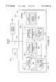
- FIG. 2is a block diagram of an image processing system in accordance with the invention.
- FIG. 3is a block diagram of FIG. 2 DIP 210 ;
- FIG. 4is a block diagram of FIG. 2 DOP 230 ;
- FIG. 5is a block diagram of FIG. 4 Transformation 404 ;
- FIG. 6illustrates the operation of FIG. 4 TGP 412 ;
- FIG. 7illustrates the operation of FIG. 6 TG LUT 608 ;
- FIG. 8shows an image having an 8 ⁇ 8 pixel resolution and a display having a 4 ⁇ 4 pixel resolution
- FIG. 9illustrates reverse super-resolution operating on an image
- FIG. 10is a flowchart illustrating DIP 210 's image processing
- FIG. 11is a flowchart illustrating DOP 230 's image processing.
- the present inventionprovides an image processing system which digitally processes one or more input data for output to a digital image modulator or to a digital memory from which a display device retrieves data.
- FIG. 2shows an image processing system 200 which includes a Display Input Processor (DIP) 210 , a Display Output Processor (DOP) 230 , and a buffer memory 240 , all coupled to a databus 250 .
- System 200also includes an image modulator 245 (comparable to FIG. 1 modulators 110 , 112 , and 114 ) coupled to DOP 230 and to an external display screen 260 .
- DIP 210preferably receives images on line 2050 and reconstructs the images both spatially and temporally.
- DIP 210 outputsare processed by DOP 230 to enhance image visual quality.
- DOP 230 outputs, preferably in frame format,are stored in frame buffer 2400 which is part of buffer memory 240 .
- Buffer memory 240stores data for use by DIP 210 and DOP 230 .
- Frame buffer 2400which stores image data for outputting to image modulator 245 or to a digital memory (not shown), is preferably part of buffer memory 240 , but alternatively can be part of the digital memory, which can in turn be part of buffer memory 240 .
- Image modulator 245can be part of a CRT- or LCD-based direct view system, displaying images that can be in pixel format on display screen 260 . However, if image modulator 245 is part of a projection system then image modulator 245 provides images to be projected and enlarged onto display screen 260 . In a projector system, image modulator 245 is small (inches) and may be either a stationary or a movable element. To increase the apparent resolution of the displayed images, a reverse super-resolution technique in accordance with the invention adjusts the data values written into a stationary image modulator 245 at an increased frame rate.
- the inventionpreferably during each output frame in a cycle, moves image modulator 245 to effectively shift the display pixel matrix a fraction of a pixel in the X and Y directions, preferably at the screen refresh rate.
- System 200processes image data in a high-resolution internal format to preserve detailed image information because such information can be lost in each of the various image processing steps if the internal image format has lower resolution than the output of image modulator 245 .
- System 200can assume that the processed image has four times (doubled vertically and horizontally) better pixel resolution than the (spatial resolution) output of image modulator 245 .
- FIG. 3is a block diagram of FIG. 2 DIP 210 , including image processing modules Analog Input Control 302 , Digital Input Control 304 , Compressed Input Control 312 , and Image Reconstruction (IR) 318 , all connected to a databus 350 .
- DIP 210also includes one or more input data connectors 300 for receiving on line 2050 image data input to system 200 , which can be one or more of analog video, digital video, non-tuned data, graphics data, or compressed data.
- Analog or digital video datamay be in a native video format such as composite video, S-video, or some component YUV/YCrCb.
- Non-tuned datareceiving from a broadcast delivery system that may have many channels on a common carrier, may require a tuner (not shown) included in or separate from DIP 210 so that relevant data can be tuned from the channels.
- Compressed datamay be in MPEG-2 format, which includes video and audio content, the data containing control or video overlay information for DOP 230 .
- Image data on line 2050may be encrypted for security and thus require decryption by DIP 210 .
- DIP 210also receives control data including for example, selected inputs, data types, vertical blanking interval (VBI) data, overlay channel information for the on-screen display (OSD), etc., and provides this control data to DOP 230 .
- VBIvertical blanking interval
- OSDon-screen display
- Each of the image processing modules, Analog Input Control 302 , Digital Input Control 304 , and Compressed Input Control 312preferably receives image data from connector 300 .
- a system microcontroller(not shown) preferably uses user-selected input controls to select image data, which is appropriately processed by each of modules 302 , 304 , and 312 , and then preferably stored in buffer memory 240 .
- the system microcontrolleralso uses the user input commands to control windowing for picture-in-picture displays, OSD information, and other system windowing capabilities.
- DIP 210preferably processes images in RGB formats. However, if applicable, for example, when the UV vectors are the same as the Y vector, DIP 210 processes images in YUV formats. In this example DIP 210 requires three times less processing power and the saved power can be applied to per pixel processing.
- Analog Input Control 302preferably includes an analog-to-digital converter (ADC) 3002 , which samples the analog data inputs and produces digital data outputs.
- ADC 3002samples its input data frequently and precisely enough that the image can be reconstructed from the sampled data points. For example, if an analog input signal is Red, Green, and Blue having data for an 800 ⁇ 600 resolution screen that is being refreshed at 70 Hz, then the data rate for each channel is approximately 50 MHz. Consequently, ADC 3002 , to properly sample the input for image reconstruction, runs at 100 MHz.
- ADC 3002preferably uses Nyquist sampling to determine the appropriate sampling rate.
- Digital Input Control 304preferably includes a synchronization engine 3040 and processes digital data, which may be in a YUV video or a digital RBG format. Since the data is already in digital format, Digital Input Control 304 does not include an analog-to-digital converter. Digital Input Control 304 also uses high-speed digital data transmittal techniques that are described in the Institute of Electrical and Electronics Engineering (IEEE) standard 1394, Low Voltage Differential Signaling (LVDS), and Panel Link. These standards include line termination, voltage control, data formatting, phase lock loops (PLLs), and data recovery to assure that Digital Input Control 304 properly receives the digital data input.
- IEEEInstitute of Electrical and Electronics Engineering
- LVDSLow Voltage Differential Signaling
- PLLsphase lock loops
- Compressed Input Control 312processes compressed data that usually includes audio, video, and system information.
- DIP 210via Compressed Input Control 312 , preferably receives compressed data because transmitting non-compressed high-speed digital data outside of system 200 (FIG. 2) is difficult and can be expensive in the cabling and component design. Further, current high speed digital interfaces are not fast enough to perform all of the panel-related processing in a separate system that requires a cable interface to a high resolution and high quality display system.
- Compressed Input Control 312prior to decompression by decompression engine 3120 , preferably demodulates the compressed digital data.
- a preprocessing systemmay demodulate the data and provide it to Compressed Input Control 312 .
- Compressed Input Control 312performing additional steps such as error correction, assures that it properly receives the data and that the data is not corrupted. If the data is corrupted, Compressed Input Control 312 may conceal the corruption or request that the data be retransmitted.
- Compressed Input Control 312once having correctly received the data, de-multiplexes the data into audio, video, and system streams, and provides the audio streams to an audio subsystem (not shown) for decoding and playback.
- Compressed Input Control 312decompresses an encoded bitstream input, but retains relevant motion vector information for DOP 230 processing.
- Bitstream Engine 3125optimizes reconstruction of MPEG-2 input bitstreams into enhanced video frames in a manner that has not been used in prior art video enhancement products.
- the bitstream informationincludes side information such as picture and sequence header flags, which can be used as control data to optimize presentation for a particular display.
- Lower-layer coded datacan reveal object shapes and other information that can be exploited to provide enhanced spatial and temporal rendering of blocks constituting images.
- Decompression engine 3120 , its decoding engine (not shown), and IR 318can use the bitstream information, for example, to better track, and thereby produce higher quality, moving objects.
- Bitstream Engine 3125to MPEG-2 encode an image frame, uses image blocks (or macroblocks). Since most video frames within a sequence are highly correlated, Bitstream Engine 3125 exploits this correlation to improve rendering. Bitstream Engine 3125 also employs motion estimation techniques for motion compensated prediction as a method of temporal processing across image frames. Bitstream Engine 3125 preferably uses a low-complexity and block-based prediction. Bitstream Engine 3125 can track the flow of video data prescribed by the prediction blocks belonging to the macroblocks within the bitstream, rather than re-estimating motion or creating the macroblocks similarly to a second pass encoding process. Bitstream Engine 3125 tracks the prediction blocks over several frames in which the temporal path of the prediction blocks delineates a coarse trajectory of moving objects.
- the motion vector of the prediction blocksincludes a horizontal component and a vertical component.
- Bitstream Engine 3125preserves the motion vector information for later use in generating DOP 230 output frames in conjunction with motion compensated temporal filtering and reverse super-resolution. The information can also be used for constructing a special block filter for post decompression filtering of the coded input stream so that IR 318 can filter artifacts of block boundary edges.
- Buffer memory 240receives data from Analog Input Control 302 , Digital Input Control 304 , and Compressed Input Control 312 , and provides the data to Image Reconstruction 318 . Buffer memory 240 also stores IR 318 output data.
- IR 318preferably includes a Motion Estimator 3180 and receives image data from Analog Input control 302 , Digital Input Control 304 , Compressed Input Control 312 , or from buffer memory 240 .
- IR 318processes data based on data types. For example, if data in YUV format requires a conversion to the RGB domain, then IR 318 , through either mathematics calculations or a look-up table, converts YUV values to RGB color space. However, IR 318 preferably processes image frames while they are still in the YUV color space and, if required, RGB color space conversion is performed during one of the last image processing steps by DOP 230 .
- YUV datais often sub-sampled, that is, one UV pair may correspond to two or four Y values. Consequently, IR 318 uses the UV values to interpolate and create RGB pixels. If YUV data is interlaced then IR 318 converts the data from field based (sequential half frames) to frame based. IR 318 stores each field in buffer memory 240 , then filters, analyzes, and combines the fields to generate an input image frame. IR 318 , if required, retransmits the processed input frames in analog video format. Nevertheless, IR 318 preferably uses the processed image frames and the motion information created by DIP 210 while the frames and the information are still in their digital format.
- IR 318processes data, such as overlay information, relevant to image modulator 245 (FIG. 2 ), IR 318 provides such data to DOP 230 to later be combined with the image data frames. IR 318 may process multiple input data streams in parallel and provide such data to DOP 230 to later produce a picture-in-picture display of multiple images. IR 318 also does post decompression filtering based on block boundary information included in the input bitstream.
- IR 318preferably uses techniques from, for example, Faroudja Labs and Snell & Willcox and Darim, that can sample and reconstruct input video, which includes composite, S-Video, and Component (Y, Cr, Cb) that may follow one of the industry standards such as Phase Alternative Line (PAL) or the National Television Standards Committee (NTS C).
- IR 318to spatially filter for high quality image frames, preferably uses various techniques for noise reduction, such as recursive, median filter, and time base correction.
- IR 318takes account of multiple input images and then, to enhance the resolution of those images, uses super-resolution techniques that employ data shared by different input frames to restore an image, and thereby to produce each output frame. This cannot be done by independently using one input image at a time.
- the inventionis thus advantageous over prior art systems which use super-resolution techniques for generating high-resolution still images from a video sequence, but not for generating output frames.
- the super-resolution techniques used by the inventiondepend on a high correlation of the data between frames, and require a sub-pixel shift of the input images, typically based on slight movements of objects in the images.
- IR 318in correlating images to restore multiple frames, uses motion vectors provided by Motion Estimator 3180 or preserved from the input bitstream.
- IR 318while generating still frames, can use mathematical equations from, for example, deterministic techniques of Projections On Convex Sets (POCS) and stochastic techniques of Bayesian enhancements.
- POCSProjections On Convex Sets
- Motion Estimator 3180When an image does not include MPEG-2 motion vector bitstream information, Motion Estimator 3180 preferably uses techniques such as optical flow, block matching, or Pel-recursion to estimate motion that tracks the image object motion in time. Motion Estimator 3180 can also use the same motion estimation techniques in conjunction with MPEG-2 motion vector bitstream information. Motion Estimator 3180 compares groups of pixels from one image field to those of subsequent and previous image fields to correlate object motion. Motion Estimator 3180 then records the detected motion relative to the field position so that DOP 230 , together with input frame information and IR 318 motion information, can later generate motion-compensated image frames.
- techniquessuch as optical flow, block matching, or Pel-recursion to estimate motion that tracks the image object motion in time. Motion Estimator 3180 can also use the same motion estimation techniques in conjunction with MPEG-2 motion vector bitstream information. Motion Estimator 3180 compares groups of pixels from one image field to those of subsequent and previous image fields to correlate object motion. Motion Estimator 3180 then records the detected motion relative to the field position so that DOP
- Motion Estimator 3180finds the best match between frames, then codes the mismatches as image “error terms.” For motion compensation, Motion Estimator 3180 masks out motion vectors that do not meet a certain level of matching criteria, and tags the vectors that have a high level of matching so that these vectors can subsequently be used in more refined motion tracking operations, which are performed on smaller image blocks or on individual pixels. Motion Estimator 3180 thus differs from prior art techniques in which video compression systems use the detected motion as one of the steps to compress the number of bits needed to represent a video sequence. Consequently, the invention, via Motion Estimator 3180 , advantageously provides better quality images than prior art techniques.
- Motion Estimator 3180tracks motion on a sub- (or smaller) block basis. For example, instead of on an 8 ⁇ 8 (pixels) block, Motion Estimator 3180 tracks motions on a 2 ⁇ 2 block, which tracks more refined motions. To reduce the need to track refined sub-blocks, Motion Estimator 3180 uses the image error terms to pre-qualify a block, and thus does not perform refined tracking on a block that has motion vectors with a high value for the error terms. Conversely, Motion Estimator 3180 does perform refined tracking on a block with a low value for the error terms.
- IR 318When receiving motion estimation vectors, such as those provided in an MPEG-2 data stream, IR 318 stores them based on the magnitude of the image error terms. IR 318 then uses vectors with high error terms only in compliant MPEG-2 decoding, and vectors with low error terms both in compliant NPEG-2 decoding and in analyzing refined motions for restoring multiple frames. Analyzing refined motions can produce motion vectors for sub-block pixel sizes, which can be used in multiframe restoration to better produce high resolution output frames.
- IR 318preferably separates its output images into video fields or frames, and creates a pointer to the start of each field (or frame). Either the actual field (or frame) data or a pointer to the field (or frame) data may serve as inputs to DOP 230 . Processing input video fields and producing frames that combine fields is useful for de-interlacing video in the image restoration process, which in turn is useful for increasing image resolution and for restoring the vertical detail that was lost during interlacing.
- IR 318 outputs (and DOP 230 outputs), having been reconstructed in accordance with the inventioncan have a higher resolution than can be supported by the number of pixels of image modulator 245 .
- IR 318 outputscan be stored in buffer memory 240 or in a metafile that includes a description of the image both in a spatial RGB frame buffer format and in a semantic description of the image objects, textures, and motions.
- FIG. 4is a block diagram of FIG. 2 DOP 230 , which has a display map memory (DMM) 402 and image processing modules including Geometric Transformation 404 , Post GT Filtering 406 , Color/Spatial Gamma Correction 410 , Temporal Gamma Processing (TGP) 412 , Reverse Super-Resolution 414 , and Display Modulation (DM) 420 , all connected to a databus 450 .
- Databus 450satisfies system bandwidth and concurrency requirements for parallel image processing.
- DOP 230also connects to buffer memory 240 , which stores data frames for use by each of the processing modules 402 , 404 , 406 , 410 , 412 , 414 , and 420 , although each of these modules may include a local memory buffer (not shown).
- DOP 230receives DIP 210 outputs either directly or via buffer memory 240 .
- DOP 230can use pointers (if applicable) to directly access DIP 210 output data.
- DOP 230also receives multiple DIP 210 output images for performing picture-in-picture operations where a single image frame includes more than one processed input video frame.
- DOP 230combines overlay data both from the input coded data and from any on-screen display (OSD) information such as a user menu selection provided by the system microcontroller.
- OSDon-screen display
- DOP 230processes its input images and outputs image data including display coordination for both video and data output, and data and control signals for each R, G, and B image color component.
- Frame buffer 2400(FIG. 2) can store DOP 230 outputs.
- DMM 402stores data corresponding to image modulator 245 (FIG. 2) characteristics at chosen pixel or screen locations. DMM 402 , where applicable, also stores a memory description corresponding to each display pixel or a shared description of groups of display pixels or pixel sectors. Because the description does not change on a frame-by-frame basis, DMM 402 preferably reads the description only once during the display process. DOP 230 then uses the description information to generate image frames. DMM 402 , when reading data, uses a set of control registers (not shown) that provide references to the data blocks.
- DMM 402 datavaries and includes, for illustrative purposes, manufacturing related information, system configuration information, and user data.
- Manufacturing related informationincludes, usually at assembly time, for example, a map of locations of defective or weak pixel display bits, correlation data of ideal radial imperfections and of optically distorted projection, and correlation data for alignment points for image modulator 245 .
- System configuration informationincludes, for example, a registration map having adjustable intensity values for each R, G, and B color component and the color component pixel offset at given locations.
- DMM 402where applicable, preferably uses sensor techniques, such as sonar range finding, infra red range finding, or laser range finding to measure distances from a projector (not shown) to different parts of display screen 260 .
- DMM 402then uses these measurements to mathematically characterize and model a projection display system. DMM 402 thus allows projecting images onto a mathematical approximation of a display screen 260 surface.
- User dataincludes user preference information such as brightness, color balance, and picture sharpness that are input by a user during a setup sequence.
- DMM 402preferably provides data, either directly or through buffer memory 240 , to Geometric Transformation module 404 .
- Geometric Transformation 404redefines the spatial relationship between pixel points of an image to provide to frame buffer 2400 compensated digital images that, when displayed, exhibit the highest possible image quality.
- Geometric transformationalso referred to as warping, includes image scaling, rotation, and translation.
- Geometric Transformation 404resamples data to produce an output image that can readily map onto FIG. 2 image modulator 245 .
- the Geometric Transformation 404 output data pointsdue to scaling or resampling, may not correspond one-to-one data points the image modulator 245 grid. Consequently, DOP 230 includes Post Geometric Transform Filtering 406 to filter the transformed data samples from Geometric Transformation 404 and produce an output pixel value for each data point of image modulator 245 .
- Post Geometric Transform Filtering 406uses spatial filtering methods to smooth the image and to resample, and thus properly space, the data samples.
- Geometric Transformation 404also improves display image characteristics related to image modulator 245 and the display system. For image modulator 245 screen regions that have more image modulator 245 pixels than screen 260 pixels, Geometric Transformation 404 adjusts the pixel values by a spatial filtering to reduce differences in neighboring pixel values. Consequently, the corresponding image (stored in frame buffer 2400 ) is smooth and does not contain artifacts. For screen display regions that have fewer image modulator 245 pixels than screen 260 pixels, Geometric Transformation 404 uses edge enhancement filtering to increase differences between neighboring pixel values to pre-compensate for distortion that will be introduced when image projection spreads out neighboring pixels.
- Geometric Transformation 404preferably uses filtering algorithms, such as nearest neighbor, bilinear, cubic convolution, sync filters, or cubic spline interpolation, to process images and thus produce accurate interpolated image pixel values. Further, where multiframe restoration requires, Geometric Transformation 404 uses time varying multiframe filtering methods including deterministic techniques such as projection onto convex sets (POCS), and stochastic techniques such as Bayesian filtering. Based on the computation complexity, Geometric Transformation 404 chooses an appropriate filtering technique.
- filtering algorithmssuch as nearest neighbor, bilinear, cubic convolution, sync filters, or cubic spline interpolation
- Geometric Transformation 404can improve image deficiencies related to the screen 260 environment. Geometric Transformation 404 performs a spatial projection which warps the image to compensate for a curved display screen 260 as is usually used in front projection theater systems, and subsequently uses bitstream information to improve the image. For example, if it can acquire the depth of moving objects, Geometric Transformation 404 can reduce the distorted motions at the edges of a curved screen 260 . Geometric Transformation 404 constructs an optical flow field of the moving objects along with the object distance information. Geometric Transformation 404 then uses motion adaptive filtering to construct a sequence of output frames that position the objects at the proper spatial coordinates in the time domain.
- Geometric Transformation 404thus, during projection on a curved screen 260 , conveys the proper motion of all objects in a scene. Geometric Transformation 404 also works in conjunction with an optical correction to improve distortions resulting from the different focal distances from a projector (not shown) to different parts of screen 260 . Geometric Transformation 404 uses range finding techniques (discussed above) to construct a model of the screen 260 environment and then uses the information from the model and the optical system to mathematically construct a formula to compensate for image distortions. Geometric Transformation 404 , to correct a warping distortion produced by an optical system, uses the same mathematical basis for a flat screen geometric transformation to apply to a curved screen.
- Geometric Transformation 404uses special processing, similar to the curved screen 260 processing, for various head-mounted displays (HMDs).
- HMDis a display unit combined with a helmet or glasses that a user wears and usually includes two image modulators 245 , one for the right eye and one for the left eye.
- HMDsare useful for a single viewer and, because of their physically smaller area, display high quality images.
- Geometric Transformation 404treats image spatial projection with warping onto a curved screen 260 in the context of 3D graphics.
- Geometric Transformation 404considers a display image frame as a 2D texture and considers a curved surface as a 3D surface.
- Geometric Transformation 404maps the 2D texture onto a surface that is the mathematical inverse of the curved screen 260 .
- Geometric Transformation 404thus pre-corrects the image frame so that, when projected, the mapped image will have filtered out the distortions associated with a curved screen 260 .
- Geometric Transformation 404preferably uses techniques such as anisotropic filtering to assure that the best texture is used in generating output pixels.
- Geometric Transformation 404also preferably uses filtering techniques such as sync filters, Wiener deconvolution, and POCS, and/or other multipass filtering techniques to filter the images off-line and then output the filtered images onto a film recorder. Geometric Transformation 404 preferably allows more computationally intensive image operations to be performed off-line.
- filtering techniquessuch as sync filters, Wiener deconvolution, and POCS, and/or other multipass filtering techniques to filter the images off-line and then output the filtered images onto a film recorder.
- Geometric Transformation 404preferably allows more computationally intensive image operations to be performed off-line.
- Geometric Transformation 404processes video as 3D texture mapping, preferably using systems that accommodate multiple textures in images.
- Geometric Transformation 404can use high quality texturing techniques such as bump mapping and displacement mapping which apply multiple texture maps to an image.
- Geometric Transformation 404modeling the graininess inherent in film, applies multi-surface texturing to give video a more film-like appearance.
- Geometric Transformation 404can allow a user to select the graininess modeling feature as part of the setup procedure similarly to selecting room effects such as “Hall,” “Stadium,” etc., in an audio playback option.
- Geometric Transformation 404can process digital data from a multi-camera system to improve the focus, and thereby provide higher quality images for image modulator 245 .
- Geometric Transformation 404evaluates which of the multiple camera views provides the best focus for an object and then reconstructs the object in proper perspective.
- Geometric Transformation 404then combines the multiple camera views on a regional or object basis to produce output images.
- Geometric Transformation 404can also use multi-camera bitstream information included in the image data to determine the object depth of a scene and to construct a 3D model of the shape and motion pattern of the moving objects. Geometric Transformation 404 then uses the same bitstream information to solve problems related to a curved screen 260 projection to achieve proper object motion completely across the screen 260 .
- Geometric Transformation 404can also improve auto stereoscopic 3D display systems in which multiple camera channels present a binocular display and each of a viewer's eye sees a different monocular view of a scene. Geometric Transformation 404 can construct each of the monocular views in accordance with the focus and motion adaptive filtering techniques described above.
- Color and Spatial Gamma Correction 4 1 0converts YUV to RGB color space and determines the intensity values for each of the R, G, and B color components. Those skilled in the art will recognize that a color space conversion is not necessary if it has been done previously or if the image is otherwise already in the RGB color space.
- Color and Spatial Gamma Correction 410preferably uses a look-up table, in which each of the R, G, and B color components has values corresponding to color intensities, to translate image colors. Each R, G, and B intensity value represents an index into the look-up table, and the table provides the output (or “translated”) value. Color and Spatial Gamma Correction 410 independently processes each R, G, or B color component.
- Color and Spatial Gamma Correction 410maps each color component based both on a combination of individual RGB values and on RGB values of surrounding pixels. For example, if FIG. 2 image modulator 245 requires a certain brightness for an identified area on display screen 260 , then Color and Spatial Gamma Correction 410 may use the RGB values of the pixels in the identified area and of the pixels in the neighboring area. Color and Spatial Gamma Correction 410 uses mathematical calculations, or preferably a color look-up table (CLUT), to provide the RGB values for the desired image outputs. Color and Spatial Gamma Correction 410 prefers using a CLUT to mathematical calculations because a CLUT allows a non-linear mapping of the input RGB values to the translated (output) RGB values.
- CLUTcolor look-up table
- a non-linear mappingenables input colors represented by RGB values to be adjusted (emphasized or de-emphasized) during the mapping process, which is useful for crosstalk suppression and for compensation of shortcomings in a color gamut of image modulator 245 .
- TGP 412assures that the time related representation of an image is as accurate as possible. TGP 412 thus, based on a previous frame value and a known transfer function of the display modulation system, adjusts its output values to provide a desired output value during a desired frame. TGP 412 independently processes each R, G, or B color component and compensates for modulating transition characteristics that, due to the nature of an LCD image modulator 245 , are not purely digital. TGP 412 also overdrives the LCD image modulator 245 to compensate for the LCD material characteristics so that the desired output can be achieved more quickly. Consequently, TGP 412 overcomes the video quality limitation of prior art systems having materials that produce fast-motioned and blurred outputs. TGP 412 can also reduce the cost of the display system because the materials used for image modulation in prior art systems that provide faster image response are usually expensive. TGP 412 is described in detail with reference to FIGS. 6 and 7.
- RSR 414performs a superset of the frame rate conversion process for converting between disparate input and output frame rates, and can improve display quality when intended display images have a higher apparent resolution than can be supported by the number of pixels of image modulator 245 .
- RSR 414simulates higher resolution outputs by sequencing lower resolution images at higher frame rates.
- RSR 414then shifts by the same pixel (or pixel fraction) amount the pixel matrix representing each RSR image block.
- RSR 414shifts the pixel matrix block Y times, once for each RSR frame, and each shift is by the same pixel (or pixel fraction) amount.
- the number of pixel fractions to be shifteddepends on the physical characteristics of the display system and of image modulator 245 . Where a system adjusts the position of the viewed image, the shift fraction corresponds to the physical movement of the viewed displayed image. Where there is no actual movement of the displayed image, the fractional adjustment is based on the physical nature of the display device such as the pixel size relative to the size of image modulator 245 and to the projection characteristics of the system.
- RSR 414then produces each RSR frame with a motion compensated weighted filtered center so that the center of the input image for each RSR frame is maintained such that no motion artifacts are introduced.
- a pixel matrix weighted filtered centeris the center of a pixel matrix taking account of filter weights in a filter transfer function. Filter weights, varying depending on the filter characteristics, are the values (usually of multiplications and additions) which are combined with the input pixel values to produce the filtered image output.
- a filter transfer functionuses filter weights to transform an input image to an output image. Output image pixels, based on a transfer function, can be adjusted to move the corresponding image.
- RSR 414preferably uses image blocks having 8 ⁇ 8 to 256 ⁇ 256 pixels where each block has uniquely processed motion information.
- RSR 414For static images, RSR 414 produces a sequence of frame-rate-adjusted output frames that are based on the difference between the input and the output frame rate. For motion pictures, RSR 414 , at the time of the output frame, portrays the intermediate position of the image and compensates for the image motion. With increased processing, each pixel or sub pixel will have its motion information processed uniquely. RSR 414 is further illustrated with reference to FIGS. 8 and 9.
- Display Modulator (DM) 420preferably receives DOP 230 (processed) output data, and controls sending of that data to image modulator 245 .
- DM 420may include control for timing updates with respect to the display timing.
- DM 420 outputsinclude separate data and control signals for each R, G, and B color component.
- DM 420 outputsfor example, can be on one or two 24-bit digital busses that drive a raster scan.
- DM 420may use voltage or frequency modulation techniques for outputs to drive image modulator 245 .
- DM 420outputs, for a flat panel display, include row and column drivers, and for each active matrix TFT, passive matrix LCD display, or other display type that requires them, includes voltage level specifications. Prior to modulating images, DM 420 determines the simplest way, the frequency, and the values represent the data to be written to image modulator 245 . DM 420 uses TGP 412 and RSR 414 , which include both compensation for the time response associated with image modulator 245 and an algorithm that increases the display update rate (or refresh rate), to increase the perceived resolution of image modulator 245 .
- DM 420stores in buffer memory 240 a copy of the previous data frame that was output to image modulator 245 , and uses this previous frame data as a delta or “difference” buffer to reduce the amount of image updating performed by DM 420 .
- DM 420compares the new data and the previous frame data for a pixel, or a group of pixels, and if the new data is the same as the previous data, DM 420 does not update that pixel, or group of pixels.
- FIG. 5is block diagram of Geometric Transformation 404 of FIG. 4 and includes image processing modules Spatial Transformation 502 , Alignment and Rotation Correction 506 , Focus Correction 508 , Distortion Correction 510 , Resampling 512 , and Multiframe Correlation 514 , all interconnect via a databus 550 .
- These processing modulesalthough they are shown as separate blocks, can be a single programmable processor performing the functions of the various module.
- Spatial Transformation 502redefines the spatial relationship between image pixel points. Spatial Transformation 502 , for example, in an X-Y alignment in a projection system with three image modulators 245 , allows each image modulator 245 to have extra pixel rows and columns. Spatial Transformation 502 then digitally adjusts the image pixels in the X-Y plane and writes the adjusted pixel data to image modulators 245 . For example, if the pixel adjustment is by an integer, Spatial Transformation 502 shifts the old imaging pixel address by the integer number of pixels to adjust. However, if the adjustment is a non-integer then Spatial Transformation 502 resamples the image with a weighted filtering algorithm to acquire new pixel values.
- Spatial Transformation 502also deals with image modulator 245 one-dimensional skew, tangential symmetry, aspect angle, and scale related distortions. Spatial Transformation 502 use resampling and weighted filtering algorithms to correct for such distortions on a pixel line by pixel line basis. Spatial Transformation 502 can perform texture mapping as in a traditional 3 D rendering process.
- Alignment/Rotation Correction 506deals with image modulator 245 two dimensional skew, tangential symmetry, aspect angle, and scale related distortions.
- Alignment/Rotation Correction 506for each R, G, and B color component, uses resampling and weighted filtering to reposition pixels in the both horizontal and vertical directions so that, when output, each color component is positioned in the proper locations across the entire image.
- Alignment/Rotation Correction 506also repositions pixels to rotate display images.
- Alignment/Rotation Correction 506to correct rotational misalignment for three image modulators 245 or geometric distortion from lenses, performs a geometric transformation to pre-compensate the images.
- Focus Correction 508improves non-uniform defocus, including defocus introduced by image modulator 245 optics. Focus Correction 508 , to account for focus problems of display screen 260 , preferably filters the image to pre-compensate the digital data representing the image. If a display screen 260 area has more image modulator 245 pixels than display screen 260 pixels, Focus Correction 508 , on a single frame basis, uses noise filtering techniques to apply linear filters, nonlinear filters, and adaptive filters. Focus Correction 508 additionally uses techniques based on POCS or other adaptive filtering techniques to pre-compensate for anticipated focus blurring.
- Focus Correction 508uses convolution techniques or reverse filtering techniques to perform edge enhancements to pre-compensate for the pixels being spread out and the image being blurred during projection.
- the spatial spread of the image due to the display systemis characterized as the display system Point Spread Function (PSF).
- PSFPoint Spread Function
- Distortion Correction 510corrects image distortion, including keystone effects.
- Distortion Correction 510provides each image with a scan line having a different scale factor to precompensate for projection distance differences.
- Distortion Correction 510starts from the upper portion of the image, filters the image, that is, permits the image to use fewer pixels on image modulator 245 so that, when projected, images on screen 260 will be proportioned properly.
- Distortion Correction 510also corrects for radial distortion introduced by lens systems. In regions where radial distortion increases the pixel density of display screen 260 , Distortion Correction 510 uses a spatial filter to reduce any differences between neighboring pixel values. Consequently, the corresponding image is smooth and does not contain artifacts including high frequency artifacts. For screen display 260 regions that have fewer pixels than display screen 260 pixels, Distortion Correction 510 uses a filtering technique to perform edge enhancements which increase differences between neighboring pixel values. This pre-compensates for the PSF distortion which will be introduced during display where neighboring pixels are spread out. Consequently, the display process smooths out images that would have had sharp edges to have a more uniform appearance. Distortion Correction 510 preferably acquires specific distortion patterns from DMM 402 .
- Resampling 512translates the pixel values from high resolution grids to new pixel values on image modulator 245 grids.
- Multiframe Correlation 514improves multiple frame display quality. For both increased and decreased pixel representations, Multiframe Correlation 514 uses algorithms such as Wiener deconvolution to exploit the temporal correlation between frames. Multiframe Correlation 514 uses multiframe techniques that process more than one input image frame to construct an optical flow field, which is further processed to construct output frames. IR 318 can provide frame inputs to Multiframe Correlation 514 . Alternatively, these frame inputs may be part of the compressed data input to Compressed Input Control 312 . Multiframe Correlation 514 can use Bayesian filtering or POCS techniques to extract multiple frame information and motion vectors showing relationships between frames from a compressed bitstream.
- Multiframe Correlation 514also converts an input frame rate to an output frame rate, for example, from 24 frames per second (fps) to 60 fps.
- Multiframe Correlation 514thus, from the sequence of 24 input frames, generates 60 unique and distinct output frames wherein all moving objects are motion-compensated so that at the time when they are displayed, they are at the proper spatial coordinates.
- Information for generating proper output framesresults from the input frame, motion estimation information, and object motion prediction.
- Motion estimation informationis either part of the MPEG-2 input bitstream or generated by Motion Estimator 3180 during image input processing.
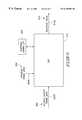
- FIG. 6illustrates the operation of FIG. 4 TGP 412 , which receives desired output frame data 600 on line 6000 and previous frame data 604 on line 6040 , and outputs value 610 on line 6100 .
- lines 6000 , 6040 and 6100are part of databus 450 (FIG. 4 ).
- Desired output frame data 600 , previous frame data 604 , and adjusted output value 610are preferably in R, G, and B color component values.
- Desired output frame 600preferably has been sampled by Resampling 512 (FIG. 5) and is provided from Geometric transformation 404 , Post GT Filtering 406 and Color/Spatial Gamma Correction 410 .
- Previous frame data 604corresponds to the last frame data of desired output frame 600 that was output to image modulator 245 .
- Previous frame data 604is preferably stored in memory buffer 240 because previous frame data 604 cannot be efficiently read from image modulator 245 , which does not provide a reliable or fast read path.
- TGP 412processing each R, G, and B color component independently for each pixel, uses previous frame data 604 to select a look-up table in temporal gamma (TG) look-up table (TG LUT) 608 , and from that selected table uses desired frame data 600 to provide adjusted value 610 .
- TGtemporal gamma
- FIG. 7illustrates the operation of FIG. 6 TG LUT 608 , which includes translation tables 704 - 1 to 704 -N.
- the number of bits representing desired output value 600determines the depth of a table 704 , that is, the number of (Red, Green, or Blue) color component intensities a table 704 can store.
- TGP 412can use a formula or a transfer function in conjunction with a previous frame value 604 to determine the output value 610 . For example, for a pixel at a location x in a pixel matrix, output value 610 J(x) may be determined by
- L(x)is the desired output value 600
- K(x)is previous frame data 604
- function Fdepends of the characteristics of image modulator 245 material.
- FIG. 8 and FIG. 9illustrate the function of RSR 414 operating on a video sequence containing images that have a spatial resolution four times higher than can be supported by the number of pixels of image modulator 245 .
- FIG. 8shows, for example, a video image 800 having an 8 ⁇ 8 pixel resolution and image modulator 245 (FIG. 2) having a 4 ⁇ 4 pixel resolution.
- the video sequence transfer rateis 24 fps.
- RSR 414filters 24 fps frames into 96 (4 ⁇ 24) fps images, and thus uses the higher spatial resolution at a higher temporal display rate, although each frame has a lower spatial resolution.
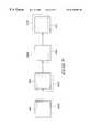
- FIG. 9shows an image frame 900 transitioned into frames 904 , 908 , and 912 .
- RSR 414block by block, spatially filters frames 900 , 904 , 908 , and 912 into transitional frames 9000 , 9040 , 9080 , and 9120 , respectively.
- RSR 414in generating frames 9000 , 9040 , 9080 , and 9120 , keeps the pixel matrix weighted filtered center of each frame 900 , 904 , 908 , and 912 constant or such that motion artifacts are not generated.
- RSR 414then filters frame 900 to frame 9000 , that is, RSR 414 resamples each frame 900 block such that each frame 900 block output pixel matrix is shifted, for example, half a pixel to the bottom and half a pixel to the right.
- RSR 414thus causes the effective center, or the weighted and spatially filtered center, of each pixel in a frame 900 block to shift to the center of what becomes the upper left quadrant of that pixel.
- Spatially filtering each block by blockallows the filter coefficients to more accurately represent the desired block outputs. Combining the block outputs produces the new output frame.
- spatially filtering each frame 900 to frame 9000causes the viewable area of frame 9000 to be one pixel less on each edge than that of frame 900 .
- RSR 414filters frame 904 to frame 9040 (again on a block by block basis). Consequently, the frame 904 output pixel matrix is shifted half a pixel to the left and half a pixel to the bottom (the weighted center of each pixel shifts to that pixel's upper right quadrant).
- RSR 414filters frame 908 to frame 9080
- RSR 414filters frame 912 to frame 9120 .
- the frame 908 output pixel matrixis shifted half a pixel to the left and half a pixel to the top (the weighted center of each pixel shifts to that pixel's lower right quadrant), and the frame 912 output pixel matrix is shifted half a pixel to the right and half a pixel to the top (the weighted center of each pixel shifts to that pixel's lower left quadrant).
- RSR 414can substitute any “pixel fraction” for “half a pixel” in the above discussion.
- the pixel fractionis determined by a system designer considering the projection path from image modulator 245 to display screen 260 and/or the pixel characteristics such as the grid spacing of the pixels versus the physical size of image modulator 245 . In this preferred embodiment, shifting and filtering images and increasing the display rate produces higher resolution display images.
- the inventioninstead of just shifting the pixel matrix, can physically move the viewed images at the display screen refresh rate, by moving either the direct screen display device 260 or image modulator 245 .
- the inventionmoves image modulator 245 .
- the inventionuses any of several techniques including Piezo electronics or micromachines to move modulator 245 .
- the inventionuses Piezo electronics to vibrate image modulator 245 , and thereby shifts modulator 245 in the X and Y directions. Assuming image modulator 245 and the pixel matrix representing an image are both square, Piezo electronics, according to the invention, uses the following equation to move image modulator 245 :
- D mis the distance in inches to move image modulator 245
- D dis the desired distance in a unit of a pixel size to move the image pixel matrix
- Sis the size in inches of an image modulator 245 side
- Image modulator 245while being moved to shift an image pixel matrix, uses data in the four frames 900 , 904 , 908 , and 912 to sample pixels for each image location of an output image, and from the four corresponding locations from the four frames 900 , 904 , 908 , and 912 , produces one location to display.
- Moving image 245is in repeated cycles. Further, during each cycle, image modulator 245 uses a corresponding sample from each of the four frames 900 , 904 , 908 , and 912 .
- the inventioncan use other techniques that allow the illusion of moving modulator 245 without physically moving any parts.
- the inventioncan use more than one LCD mirror to reflect the image through the display projection system where each mirror has a slightly different projection angle.
- the inventionuses the LCD mirrors to create a sequence of projected images with slightly different positions.
- the inventioncan also use lenticular lens, LCD mirror, or multi-layered micro display technologies to move the viewed image without moving image modulator 245 .
- RSR 414produces, for static images, an output which is stable to a viewer because human vision interpolates multiple images to form one continuous image view.
- RSR 414uses motion-adaptive filters, including median filters, that include motion tracking to filter each block constituting each image frame ( 900 , 904 , etc.).
- Motion-adaptive filteringaccounts for positions of moving objects between intermediate frames created by RSR 414 . For example, an object may be moving along an X axis from a position 6 in a frame i to a position 10 in a frame k. If RSR 414 creates an intermediate frame j, then the moving object will be positioned at location 8 in frame j, which is half way between location 6 in frame i and location 10 in frame k.
- RSR 414used in combination with motion-adaptive filtering, weights the RSR frames and compensates for motions between frames.
- RSR 414also uses the block-based motion estimation from the MPEG-2 motion vectors or from Motion Estimator 3180 to track motion in the image.
- RSR 414first identifies the motion blocks of the objects within an image, then allows successive output frames to utilize the image object motion information and to move the center weighting for the corresponding pixels to correlate to the object motion.
- RSR 414also uses multiple input frames or fields to track the trajectory and velocity of moving objects and thereby predicts the object spatial position in a frame. As a result, RSR 414 greatly reduces or even eliminates motion artifacts.
- RSR 414thus can produce images having higher resolution than can be supported by the number of pixels of image modulator 245 , and provide a high resolution system without incurring increased cost as is usually found in prior art high resolution systems.
- RSR 414can extract the motion tracking information directly from the bitstream, which preferably includes the data to discern which blocks contain moving objects and the object movement patterns. Alternatively, RSR 414 can extract the same motion tracking information from post-decoded (or decompressed) frames. RSR 414 then provides the motion tracking information to the filtering algorithms.
- RSR 414can improve FEDs and the class of displays defined as those in which each pixel is made up of a matrix of emitting elements. For example, RSR 414 combines the FED mesh cell configuration and its address control to perform RSR and, from high resolution images, sequences a high resolution output using a FED that has a lower number of addressable pixels. RSR 414 uses the same techniques for generating the spatially filtered RSR frames to determine the sequence of lower resolution images. RSR 414 then, taking advantage of the sub-pixel addressing within a pixel that is unique to the microtips and mesh structure of the FED, writes the sequence of the frames within the FED sub pixel addressing. The resolution of FEDs is defined as the ability to individually address a pixel.
- FEDscan be designed with an internal function to adjust the mesh cell emitter positions for data already stored in the pixels. In this way the position of the image is moved without a new image being loaded into the pixels. Sequentially modulating images within the FED mesh structure constructs a display image that has higher resolution than the addressable resolution of the FED display would otherwise allow.
- FIG. 10is a flowchart illustrating DIP 210 's image processing steps in selecting and reconstructing images.
- DIP 210where applicable, preferably creates a database to store motion information for later use by DOP 230 .
- system 200via connector 300 of DIP 210 , receives input images.
- a microcontrollerpreferably selects one or more input images and provides each image to appropriate image processing modules Analog Input Control 302 , Digital Input Control 304 , and Compressed Input Control 312 .
- Each processing module 302 , 304 , and 312 in step 1012samples, and thereby recovers, the input images.
- Analog Input Control 302may discard unnecessary or repeated input fields.
- Compressed Input Control 312via Bitstream Engine 3125 , analyzes the compressed input streams and selects one or more picture streams for analysis and processing.
- Bitstream Engine 3125records the motion information from the bitstream for use in the image reconstruction steps 1020 , 1024 , and 1028 , and by the DOP 230 .
- Bitstream Engine 3125based on a quality trade-off decision, can select a single picture or decode multiple pictures. This is because system 200 may not have the compute power required to process multiple input streams at full quality. If multiple pictures are to be displayed simultaneously, each picture will only be a portion of the total display output and thus can cause lower visual display quality than if a single picture were used for the full output.
- Bitstream Engine 3125while sampling a compressed stream, may extract multiple picture streams, and, if required, reduce the complexity of the multiple picture streams to be processed.
- each processing module 302 , 304 , and 312preferably formats the images and stores them in buffer 240 .
- Decompression Engine 3120preferably uses the MPEG-2 decompression steps to convert the compressed bitstream into a decompressed and decoded picture.
- Decompression Engine 3120can simultaneously decompress more than one compressed picture stream for multiple picture displays including advanced picture-in-picture displays and multi-camera systems.
- Decompression Engine 3120can decode both layers for use by the Image Reconstruction 318 .
- Image Reconstruction 318 in step 1020spatially filters each image frame to reconstruct 2D images.
- Spatial filteringincludes various techniques for noise reduction so that the filtered image does not include artifacts that were not part of the original image. Filtering is preferably applied across the entire input image based on the data values. However, filtering can use additional information, such as spatial position of the decoded macroblocks, that is provided by the Bitstream Engine 3125 in cases where, for example, the MPEG-2 data has been decompressed by Decompression Engine 3120 . This positional information allows the filter to reduce or eliminate artifacts from boundary edges from the decoded macroblocks while performing the more traditional spatial filtering on the other portions of the image.
- Image Reconstruction 318performs scene analysis on each of the spatially filtered input images.
- Image Reconstruction 318analyzes and arranges the scene data as groups of pixels for use by the Motion Estimator 3180 .
- Image Reconstruction 318can combine the motion vector information, which is usually block based, with the decoded and filtered images to recognize image objects.
- Image Reconstruction 318can apply a filter, such as a sharpening convolution filter, to enhance the image edges.
- Image Reconstruction 318via the enhancement filtering that uses information from the Bitstream Engine 3125 , can enhance input image details without amplifying the compression artifacts.
- Image Reconstruction 318 in step 1028performs temporal analysis, which utilizes multiple scenes to filter the images and to record the object motion information, then performs a super-resolution multiframe restoration. For input data that was interlaced, Image Reconstruction 318 de-interlaces the input fields. Image Reconstruction 318 , using temporal analysis, performs median filtering and reconstructs the spatial resolution of each image based on the information from the neighboring images. Image Reconstruction 318 uses Motion Estimator 3180 to estimate the motion information for objects that were detected during the scene analysis in step 1024 .
- Image Reconstruction 318 in steps 1020 , 1024 , and 1028can utilize additional information from an input stream such as a layered coding including picture-layer flags and coded information for object shape information.
- FIG. 11is a flowchart illustrating DOP 230 's image processing steps.
- DOP 230 in step 1104receives DIP 210 outputs which include both the spatially enhanced image and supplemental information that includes, for example, motion information, other object or block based information, sensor or multi-camera view information, and other information about the images.
- DOP 230combines DIP 210 outputs with the display system information to perform image geometric transformation including spatial transformation, alignment/rotation, focus, and distortion correction.
- Geometric transformationcan improve display deficiencies related to the display environment, such as introduced by image modulator 245 , display screen 260 , and display system optics 120 .
- Geometric transformationcan also produce enhanced output images that correct for special environments such as head-mounted, panoramic, and stereoscopic display systems.
- the spatial filtering techniques of Geometric Transformation 404can use traditional real-time 3D graphics techniques such as texture mapping to achieve the desired image manipulations.
- Multiframe Correlation 514uses motion vector information, either alone, or in combination with the original bitstream input, a Bitstream Engine 3125 enhanced version of the original bitstream, or the Motion Estimator 3180 . Combining the spatial and temporal processing that utilizes the information of multi frames (versus just one frame) allows increasing the image output resolution, which, along with other steps, allows the image output resolution to be higher than the input resolution.
- DOP 230 in step 1112performs frame rate conversion (FRC), which also uses the motion vector information in motion compensated filtering.
- FRCis usually required where the input frame rate is different than the output frame rate.
- FRCuses both the transformed image data and the supplemental information, such as motion vector information, to produce a unique set of motion compensated output frames. These unique output frames temporally adjust the output images to produce smooth and accurate motion portrayal.
- DOP 230can use motion vector information to produce an output image where an object that changes location from one input frame to the next is shown to be fractionally between the two locations for the output frame.
- DOP 230also uses motion compensated filtering for the special display environments such as a panoramic system where the motion portrayal needs to correct for the non-uniform nature of having a curved display screen 260 .
- step 1116DOP 230 , via RSR 414 , performs image RSR, which is a special case of FRC where the output frame sequencing is not only for motion portrayal, but also for increasing the apparent spatial resolution of the display.
- RSRis particularly applicable to display systems where image modulator 245 supports a high refresh rate.
- RSR 414may perform system frame rate conversion.
- Multiframe Correlation 514 of Geometric Transformation 404may generate the RSR frames.
- RSRproduces the highest image quality when the motion compensated filtering is carefully matched to small block sizes or to individual pixels.
- RSR 414utilizes motion vectors for generating output frames.
- DOP 230uses Color/Spatial Gamma Correction 410 and Temporal Gamma Processing 412 to perform gamma correction both spatially and temporally.
- Gamma correctiontranslates each display pixel and assures that the display system achieves the full color gamut.
- Gamma correctionpreferably uses gamma correction tables loaded during system configuration.
- DOP 230uses Display Modulator 420 to control the sending of display images to image modulator 245 .
- Display Modulator 420may sequence or control the output of more than one output image.
- DOP 230 in steps 1112 , 1116 , 1120 , and 1124takes account of manufacturing defects, calibration data, environment effects, and user controlled setup information.
- Each processing step 1112 , 1116 , 1120 , and 1124can also support multiple simultaneous images that are used for a multiple window display or advanced picture-in-picture display. Additional display output information such as on-screen display and overlay information is also merged into the display stream such that it becomes part of the output image.
- DOP 230 in step 1128sends display images and control information to a digital memory or image modulator 245 , which provides images to display screen 260 , either directly or through a projector.
- a digital memory or image modulator 245which provides images to display screen 260 , either directly or through a projector.
- system 200 of the inventioncan be implemented in either hardware or software or some combination of fixed function, configurable logic or programmable hardware.
Landscapes
- Engineering & Computer Science (AREA)
- Multimedia (AREA)
- Signal Processing (AREA)
- Physics & Mathematics (AREA)
- Computer Hardware Design (AREA)
- General Physics & Mathematics (AREA)
- Theoretical Computer Science (AREA)
- Geometry (AREA)
- Control Of Indicators Other Than Cathode Ray Tubes (AREA)
Abstract
Description
Claims (32)
Priority Applications (2)
| Application Number | Priority Date | Filing Date | Title |
|---|---|---|---|
| US09/277,100US6340994B1 (en) | 1998-08-12 | 1999-03-26 | System and method for using temporal gamma and reverse super-resolution to process images for use in digital display systems |
| US10/792,172US7496236B2 (en) | 1998-08-12 | 2004-03-02 | Video coding reconstruction apparatus and methods |
Applications Claiming Priority (2)
| Application Number | Priority Date | Filing Date | Title |
|---|---|---|---|
| US9632298P | 1998-08-12 | 1998-08-12 | |
| US09/277,100US6340994B1 (en) | 1998-08-12 | 1999-03-26 | System and method for using temporal gamma and reverse super-resolution to process images for use in digital display systems |
Related Parent Applications (1)
| Application Number | Title | Priority Date | Filing Date |
|---|---|---|---|
| US09/250,424Continuation-In-PartUS6157396A (en) | 1998-08-12 | 1999-02-16 | System and method for using bitstream information to process images for use in digital display systems |
Related Child Applications (1)
| Application Number | Title | Priority Date | Filing Date |
|---|---|---|---|
| US10/792,172Continuation-In-PartUS7496236B2 (en) | 1998-08-12 | 2004-03-02 | Video coding reconstruction apparatus and methods |
Publications (1)
| Publication Number | Publication Date |
|---|---|
| US6340994B1true US6340994B1 (en) | 2002-01-22 |
Family
ID=26791566
Family Applications (1)
| Application Number | Title | Priority Date | Filing Date |
|---|---|---|---|
| US09/277,100Expired - LifetimeUS6340994B1 (en) | 1998-08-12 | 1999-03-26 | System and method for using temporal gamma and reverse super-resolution to process images for use in digital display systems |
Country Status (1)
| Country | Link |
|---|---|
| US (1) | US6340994B1 (en) |
Cited By (211)
| Publication number | Priority date | Publication date | Assignee | Title |
|---|---|---|---|---|
| US20010026326A1 (en)* | 2000-03-28 | 2001-10-04 | Nec Corporation | Display control method for video display system and video display system |
| US20020063666A1 (en)* | 2000-06-28 | 2002-05-30 | Kang Sin Ho | Apparatus and method for correcting gamma voltage and video data in liquid crystal display |
| US20020071493A1 (en)* | 2000-05-17 | 2002-06-13 | Akira Shirahama | Image processing apparatus, image processing method, and recording medium |
| US20020109693A1 (en)* | 2001-02-15 | 2002-08-15 | Mark Champion | Checkerboard buffer using two-dimensional buffer pages |
| US20020109792A1 (en)* | 2001-02-15 | 2002-08-15 | Mark Champion | Two-dimensional buffer pages using memory bank alternation |
| US20020118454A1 (en)* | 2000-10-13 | 2002-08-29 | John Hey | System for stereoscopic viewing of an image |
| US20020180890A1 (en)* | 2001-05-21 | 2002-12-05 | Milne James R. | Modular digital television architecture |
| US6491400B1 (en)* | 2000-10-24 | 2002-12-10 | Eastman Kodak Company | Correcting for keystone distortion in a digital image displayed by a digital projector |
| WO2002073245A3 (en)* | 2001-03-08 | 2002-12-19 | Ball Semiconductor Inc | High power incoherent light source with laser array |
| US20030001981A1 (en)* | 2001-05-21 | 2003-01-02 | Sony Corporation | Modular digital television architecture |
| US20030058368A1 (en)* | 2001-09-24 | 2003-03-27 | Mark Champion | Image warping using pixel pages |
| US20030063670A1 (en)* | 2001-09-28 | 2003-04-03 | Koichi Masukura | Image data processing method and article of manufacture |
| US20030128179A1 (en)* | 2002-01-07 | 2003-07-10 | Credelle Thomas Lloyd | Color flat panel display sub-pixel arrangements and layouts for sub-pixel rendering with split blue sub-pixels |
| US20030128225A1 (en)* | 2002-01-07 | 2003-07-10 | Credelle Thomas Lloyd | Color flat panel display sub-pixel arrangements and layouts for sub-pixel rendering with increased modulation transfer function response |
| US20030142875A1 (en)* | 1999-02-04 | 2003-07-31 | Goertzen Kenbe D. | Quality priority |
| US6628317B2 (en)* | 2000-02-17 | 2003-09-30 | Fuji Photo Film Co., Ltd. | Optical printer with micromirror device |
| US20030185455A1 (en)* | 1999-02-04 | 2003-10-02 | Goertzen Kenbe D. | Digital image processor |
| US20030206242A1 (en)* | 2000-03-24 | 2003-11-06 | Choi Seung Jong | Device and method for converting format in digital TV receiver |
| US6657603B1 (en)* | 1999-05-28 | 2003-12-02 | Lasergraphics, Inc. | Projector with circulating pixels driven by line-refresh-coordinated digital images |
| US20040017853A1 (en)* | 2002-05-29 | 2004-01-29 | Diego Garrido | Maintaining a plurality of codebooks related to a video signal |
| US20040031060A1 (en)* | 2001-04-12 | 2004-02-12 | Tetsujiro Kondo | Signal processing device, housing rack, and connector |
| EP1391866A1 (en)* | 2002-08-23 | 2004-02-25 | Deutsche Thomson Brandt | Adaptive noise reduction for digital display panels |
| US20040071211A1 (en)* | 1997-04-07 | 2004-04-15 | Kinya Washino | Video production system with mixed frame removal |
| US20040109060A1 (en)* | 2002-10-22 | 2004-06-10 | Hirotaka Ishii | Car-mounted imaging apparatus and driving assistance apparatus for car using the imaging apparatus |
| US6819944B1 (en)* | 1999-05-17 | 2004-11-16 | Nec Corporation | Mobile terminal equipped with adapter for image display and method for handling changes in connection line quality |
| US6829371B1 (en)* | 2000-04-29 | 2004-12-07 | Cognex Corporation | Auto-setup of a video safety curtain system |
| US20040246268A1 (en)* | 2002-05-13 | 2004-12-09 | Hari Nair | Apparatus and method for multi-resolution color mapping for display devices |
| US20040263502A1 (en)* | 2003-04-24 | 2004-12-30 | Dallas James M. | Microdisplay and interface on single chip |
| US20050024368A1 (en)* | 2001-02-15 | 2005-02-03 | Xiping Liu | Two dimensional buffer pages |
| US20050025388A1 (en)* | 2003-07-31 | 2005-02-03 | Niranjan Damera-Venkata | Generating and displaying spatially offset sub-frames |
| WO2005017817A1 (en)* | 2003-08-04 | 2005-02-24 | Grass Valley (U.S.) Inc. | Apparatus and method for reducing noise in an image |
| US20050057572A1 (en)* | 2001-02-15 | 2005-03-17 | Sony Corporation | Checkerboard buffer |
| WO2005038720A1 (en)* | 2003-10-17 | 2005-04-28 | Leapfrog Enterprises, Inc. | Edge smoothing systems and methods |
| US20050088385A1 (en)* | 2003-10-28 | 2005-04-28 | Elliott Candice H.B. | System and method for performing image reconstruction and subpixel rendering to effect scaling for multi-mode display |
| US20050093895A1 (en)* | 2003-10-30 | 2005-05-05 | Niranjan Damera-Venkata | Generating and displaying spatially offset sub-frames on a diamond grid |
| US20050094899A1 (en)* | 2003-10-29 | 2005-05-05 | Changick Kim | Adaptive image upscaling method and apparatus |
| US20050104890A1 (en)* | 2001-02-15 | 2005-05-19 | Sony Corporation | Dynamic buffer pages |
| US20050111760A1 (en)* | 2003-11-26 | 2005-05-26 | Lal Rakesh M. | Resolution adaptive image filtering system and method |
| US6900821B2 (en)* | 2000-02-02 | 2005-05-31 | Quvis, Inc. | System and method for optimizing image resolution using pixelated imaging device |
| US20050117798A1 (en)* | 2003-12-02 | 2005-06-02 | Eastman Kodak Company | Method and apparatus for modifying a portion of an image frame in accordance with colorimetric parameters |
| EP1542161A1 (en)* | 2003-12-10 | 2005-06-15 | Sony Corporation | Image processing method and apparatus, and program |
| US20050129130A1 (en)* | 2003-12-10 | 2005-06-16 | Microsoft Corporation | Color space coding framework |
| US20050171558A1 (en)* | 2003-10-17 | 2005-08-04 | Abovitz Rony A. | Neurosurgery targeting and delivery system for brain structures |
| US20050177662A1 (en)* | 2002-04-04 | 2005-08-11 | Hauke Michael T. | Modular broadcast television products |
| US6942152B1 (en)* | 2004-01-21 | 2005-09-13 | The Code Corporation | Versatile graphical code reader that is configured for efficient decoding |
| US20050225568A1 (en)* | 2004-04-08 | 2005-10-13 | Collins David C | Generating and displaying spatially offset sub-frames |
| US20050225570A1 (en)* | 2004-04-08 | 2005-10-13 | Collins David C | Generating and displaying spatially offset sub-frames |
| US20050225571A1 (en)* | 2004-04-08 | 2005-10-13 | Collins David C | Generating and displaying spatially offset sub-frames |
| US20050275642A1 (en)* | 2004-06-09 | 2005-12-15 | Aufranc Richard E Jr | Generating and displaying spatially offset sub-frames |
| US20050275646A1 (en)* | 2004-06-14 | 2005-12-15 | Hannstar Display Corporation | Driving system and driving method for motion pictures |
| US20060082567A1 (en)* | 2002-08-07 | 2006-04-20 | William Allen | Image display system and method |
| US20060092189A1 (en)* | 2002-08-07 | 2006-05-04 | Allen William J | Image display system and method |
| US20060095472A1 (en)* | 2004-06-07 | 2006-05-04 | Jason Krikorian | Fast-start streaming and buffering of streaming content for personal media player |
| US20060110072A1 (en)* | 2004-11-19 | 2006-05-25 | Nairanjan Domera-Venkata | Generating and displaying spatially offset sub-frames |
| US20060117371A1 (en)* | 2001-03-15 | 2006-06-01 | Digital Display Innovations, Llc | Method for effectively implementing a multi-room television system |
| US20060176407A1 (en)* | 2005-02-08 | 2006-08-10 | Texas Instruments Incorporated | Real-time content based gamma adjustment for digital video display |
| US20060181758A1 (en)* | 2005-02-14 | 2006-08-17 | Willis Thomas E | Spatial light modulator |
| US20060238524A1 (en)* | 2005-04-22 | 2006-10-26 | Kuan-Hong Hsieh | Signal conversion apparatus for display device |
| US20060282855A1 (en)* | 2005-05-05 | 2006-12-14 | Digital Display Innovations, Llc | Multiple remote display system |
| US20070003224A1 (en)* | 2005-06-30 | 2007-01-04 | Jason Krikorian | Screen Management System for Media Player |
| US20070022328A1 (en)* | 2005-06-30 | 2007-01-25 | Raghuveer Tarra | Firmware Update for Consumer Electronic Device |
| US20070035707A1 (en)* | 2005-06-20 | 2007-02-15 | Digital Display Innovations, Llc | Field sequential light source modulation for a digital display system |
| US20070035706A1 (en)* | 2005-06-20 | 2007-02-15 | Digital Display Innovations, Llc | Image and light source modulation for a digital display system |
| US20070046821A1 (en)* | 2005-08-26 | 2007-03-01 | John Mead | Video image processing with remote diagnosis and programmable scripting |
| US20070046820A1 (en)* | 2005-08-26 | 2007-03-01 | John Mead | Video image processing with programmable scripting and remote diagnosis |
| US20070057960A1 (en)* | 2005-09-15 | 2007-03-15 | Kabushiki Kaisha Toshiba | Image display method and apparatus |
| US20070071342A1 (en)* | 2005-09-29 | 2007-03-29 | Brett Bilbrey | Video acquisition with integrated GPU processing |
| US20070071344A1 (en)* | 2005-09-29 | 2007-03-29 | Ouzilevski Alexei V | Video acquisition with integrated GPU processing |
| US20070071343A1 (en)* | 2005-09-29 | 2007-03-29 | Jay Zipnick | Video acquisition with integrated GPU processing |
| US20070091997A1 (en)* | 2003-05-28 | 2007-04-26 | Chad Fogg | Method And Apparatus For Scalable Video Decoder Using An Enhancement Stream |
| US20070097326A1 (en)* | 2005-10-28 | 2007-05-03 | Jung-Yi Yang | Digital rear-projection display apapratus and method for adjusting a displayed image thereof |
| US20070097130A1 (en)* | 2005-11-01 | 2007-05-03 | Digital Display Innovations, Llc | Multi-user terminal services accelerator |
| US20070124474A1 (en)* | 2005-11-30 | 2007-05-31 | Digital Display Innovations, Llc | Multi-user display proxy server |
| US20070211013A1 (en)* | 2006-03-03 | 2007-09-13 | Nec Corporation | Light source apparatus, display apparatus, terminal apparatus, and control method thereof |
| US20070211913A1 (en)* | 2006-03-13 | 2007-09-13 | Konica Minolta Business Technologies, Inc. | Image processing apparatus, image processing method, and computer readable recording medium storing program |
| US20070211000A1 (en)* | 2006-03-08 | 2007-09-13 | Kabushiki Kaisha Toshiba | Image processing apparatus and image display method |
| US20070234213A1 (en)* | 2004-06-07 | 2007-10-04 | Jason Krikorian | Selection and Presentation of Context-Relevant Supplemental Content And Advertising |
| WO2007089803A3 (en)* | 2006-01-31 | 2007-10-11 | Thomson Licensing | Methods and apparatus for edge-based spatio-temporal filtering |
| WO2007132792A1 (en)* | 2006-05-12 | 2007-11-22 | Panasonic Corporation | Image processing apparatus, method and integrated circuit |
| US20070284002A1 (en)* | 2006-06-09 | 2007-12-13 | Hartman Brian T | Fixed cone sleeve valve having cone supported by means downstream of the gate in its closed position |
| US20080024467A1 (en)* | 2006-07-26 | 2008-01-31 | Collins David C | Determining sequence of frames delineated into sub-frames for displaying on display device |
| US20080094419A1 (en)* | 2006-10-24 | 2008-04-24 | Leigh Stan E | Generating and displaying spatially offset sub-frames |
| US20080095468A1 (en)* | 2004-08-30 | 2008-04-24 | Bauhaus-Universitaet Weimar | Method And Device For Representing A Digital Image On A Surface Which Is Non-Trivial In Terms Of Its Geometry And Photometry |
| US20080112489A1 (en)* | 2006-11-09 | 2008-05-15 | Calista Technologies | System and method for effectively encoding and decoding electronic information |
| WO2008086078A1 (en)* | 2007-01-05 | 2008-07-17 | Silicon Optix, Inc. | Color and geometry distortion correction system and method |
| US20080256485A1 (en)* | 2007-04-12 | 2008-10-16 | Jason Gary Krikorian | User Interface for Controlling Video Programs on Mobile Computing Devices |
| US20080288211A1 (en)* | 2005-03-29 | 2008-11-20 | France Telecom | Method and Device for the Evaluation of a Quality of Signal Representing at Least One Stimulus, as Perceived by a Recipient of Said Stimulus |
| US20090213238A1 (en)* | 2008-02-26 | 2009-08-27 | Canon Kabushiki Kaisha | Image capturing apparatus |
| US20100001960A1 (en)* | 2008-07-02 | 2010-01-07 | Sling Media, Inc. | Systems and methods for gestural interaction with user interface objects |
| US7667707B1 (en) | 2005-05-05 | 2010-02-23 | Digital Display Innovations, Llc | Computer system for supporting multiple remote displays |
| US20100045690A1 (en)* | 2007-01-04 | 2010-02-25 | Handschy Mark A | Digital display |
| US20100064332A1 (en)* | 2008-09-08 | 2010-03-11 | Sling Media Inc. | Systems and methods for presenting media content obtained from multiple sources |
| US7720300B1 (en) | 2006-12-05 | 2010-05-18 | Calister Technologies | System and method for effectively performing an adaptive quantization procedure |
| US7725912B2 (en) | 1999-05-26 | 2010-05-25 | Sling Media, Inc. | Method for implementing a remote display system with transcoding |
| US20100253845A1 (en)* | 2009-04-06 | 2010-10-07 | Nec Electronics Corporation | Image processing method and image processing apparatus |
| US20100309336A1 (en)* | 2009-06-05 | 2010-12-09 | Apple Inc. | Skin tone aware color boost for cameras |
| US20110035467A1 (en)* | 2009-08-10 | 2011-02-10 | Sling Media Pvt Ltd | Localization systems and methods |
| US20110035741A1 (en)* | 2009-08-10 | 2011-02-10 | Sling Media Pvt Ltd | Systems and methods for updating firmware over a network |
| US7917932B2 (en) | 2005-06-07 | 2011-03-29 | Sling Media, Inc. | Personal video recorder functionality for placeshifting systems |
| US20110153718A1 (en)* | 2009-12-22 | 2011-06-23 | Sling Media Inc. | Systems and methods for establishing network connections using local mediation services |
| US20110158610A1 (en)* | 2009-12-28 | 2011-06-30 | Sling Media Inc. | Systems and methods for searching media content |
| US7975062B2 (en) | 2004-06-07 | 2011-07-05 | Sling Media, Inc. | Capturing and sharing media content |
| US20110191456A1 (en)* | 2010-02-03 | 2011-08-04 | Sling Media Pvt Ltd | Systems and methods for coordinating data communication between two devices |
| US20110196521A1 (en)* | 2010-02-05 | 2011-08-11 | Sling Media Inc. | Connection priority services for data communication between two devices |
| US20110208506A1 (en)* | 2010-02-24 | 2011-08-25 | Sling Media Inc. | Systems and methods for emulating network-enabled media components |
| US8019883B1 (en) | 2005-05-05 | 2011-09-13 | Digital Display Innovations, Llc | WiFi peripheral mode display system |
| US8060609B2 (en) | 2008-01-04 | 2011-11-15 | Sling Media Inc. | Systems and methods for determining attributes of media items accessed via a personal media broadcaster |
| US20120001945A1 (en)* | 2010-06-29 | 2012-01-05 | Promethean Limited | Fine Object Positioning |
| US8099755B2 (en) | 2004-06-07 | 2012-01-17 | Sling Media Pvt. Ltd. | Systems and methods for controlling the encoding of a media stream |
| US8171148B2 (en) | 2009-04-17 | 2012-05-01 | Sling Media, Inc. | Systems and methods for establishing connections between devices communicating over a network |
| US8200796B1 (en) | 2005-05-05 | 2012-06-12 | Digital Display Innovations, Llc | Graphics display system for multiple remote terminals |
| US20120195518A1 (en)* | 2011-01-28 | 2012-08-02 | Ability Enterprise Co., Ltd. | Image compensation method and system |
| US20120212486A1 (en)* | 2009-11-03 | 2012-08-23 | Koninklijke Philips Electronics N.V. | Autostereoscopic display device |
| US8305301B1 (en) | 2003-02-04 | 2012-11-06 | Imaging Systems Technology | Gamma correction |
| US8314893B2 (en) | 2009-08-28 | 2012-11-20 | Sling Media Pvt. Ltd. | Remote control and method for automatically adjusting the volume output of an audio device |
| US20120320036A1 (en)* | 2011-06-17 | 2012-12-20 | Lg Display Co., Ltd. | Stereoscopic Image Display Device and Driving Method Thereof |
| US8346605B2 (en) | 2004-06-07 | 2013-01-01 | Sling Media, Inc. | Management of shared media content |
| US8350971B2 (en) | 2007-10-23 | 2013-01-08 | Sling Media, Inc. | Systems and methods for controlling media devices |
| US8381310B2 (en) | 2009-08-13 | 2013-02-19 | Sling Media Pvt. Ltd. | Systems, methods, and program applications for selectively restricting the placeshifting of copy protected digital media content |
| US8406431B2 (en) | 2009-07-23 | 2013-03-26 | Sling Media Pvt. Ltd. | Adaptive gain control for digital audio samples in a media stream |
| US8438602B2 (en) | 2009-01-26 | 2013-05-07 | Sling Media Inc. | Systems and methods for linking media content |
| US20130113876A1 (en)* | 2010-09-29 | 2013-05-09 | Huawei Device Co., Ltd. | Method and Device for Multi-Camera Image Correction |
| US8477793B2 (en) | 2007-09-26 | 2013-07-02 | Sling Media, Inc. | Media streaming device with gateway functionality |
| US8532472B2 (en) | 2009-08-10 | 2013-09-10 | Sling Media Pvt Ltd | Methods and apparatus for fast seeking within a media stream buffer |
| US20130307835A1 (en)* | 2012-05-16 | 2013-11-21 | Himax Technologies Limited | Panel control apparatus and operating method thereof |
| US8667279B2 (en) | 2008-07-01 | 2014-03-04 | Sling Media, Inc. | Systems and methods for securely place shifting media content |
| US8667163B2 (en) | 2008-09-08 | 2014-03-04 | Sling Media Inc. | Systems and methods for projecting images from a computer system |
| US8799485B2 (en) | 2009-12-18 | 2014-08-05 | Sling Media, Inc. | Methods and apparatus for establishing network connections using an inter-mediating device |
| US20140267371A1 (en)* | 2013-03-15 | 2014-09-18 | Google Inc. | Gpu-accelerated, two-pass colorspace conversion using multiple simultaneous render targets |
| WO2014149902A1 (en)* | 2013-03-15 | 2014-09-25 | Pelican Imaging Corporation | Systems and methods for providing an array projector |
| US8891010B1 (en)* | 2011-07-29 | 2014-11-18 | Pixelworks, Inc. | Encoding for super resolution playback |
| US9015225B2 (en) | 2009-11-16 | 2015-04-21 | Echostar Technologies L.L.C. | Systems and methods for delivering messages over a network |
| US9160974B2 (en) | 2009-08-26 | 2015-10-13 | Sling Media, Inc. | Systems and methods for transcoding and place shifting media content |
| US9178923B2 (en) | 2009-12-23 | 2015-11-03 | Echostar Technologies L.L.C. | Systems and methods for remotely controlling a media server via a network |
| US9191610B2 (en) | 2008-11-26 | 2015-11-17 | Sling Media Pvt Ltd. | Systems and methods for creating logical media streams for media storage and playback |
| US9247117B2 (en) | 2014-04-07 | 2016-01-26 | Pelican Imaging Corporation | Systems and methods for correcting for warpage of a sensor array in an array camera module by introducing warpage into a focal plane of a lens stack array |
| US20160275684A1 (en)* | 2013-11-14 | 2016-09-22 | Koninklijke Philips N.V. | Registration of medical images |
| US9479737B2 (en) | 2009-08-06 | 2016-10-25 | Echostar Technologies L.L.C. | Systems and methods for event programming via a remote media player |
| US9485496B2 (en) | 2008-05-20 | 2016-11-01 | Pelican Imaging Corporation | Systems and methods for measuring depth using images captured by a camera array including cameras surrounding a central camera |
| US9525838B2 (en) | 2009-08-10 | 2016-12-20 | Sling Media Pvt. Ltd. | Systems and methods for virtual remote control of streamed media |
| US9565479B2 (en) | 2009-08-10 | 2017-02-07 | Sling Media Pvt Ltd. | Methods and apparatus for seeking within a media stream using scene detection |
| TWI570701B (en)* | 2009-12-18 | 2017-02-11 | 半導體能源研究所股份有限公司 | Method of driving liquid crystal display device |
| US9706132B2 (en) | 2012-05-01 | 2017-07-11 | Fotonation Cayman Limited | Camera modules patterned with pi filter groups |
| US9733486B2 (en) | 2013-03-13 | 2017-08-15 | Fotonation Cayman Limited | Systems and methods for controlling aliasing in images captured by an array camera for use in super-resolution processing |
| US9743051B2 (en) | 2013-02-24 | 2017-08-22 | Fotonation Cayman Limited | Thin form factor computational array cameras and modular array cameras |
| US9749547B2 (en) | 2008-05-20 | 2017-08-29 | Fotonation Cayman Limited | Capturing and processing of images using camera array incorperating Bayer cameras having different fields of view |
| US9749568B2 (en) | 2012-11-13 | 2017-08-29 | Fotonation Cayman Limited | Systems and methods for array camera focal plane control |
| US9754422B2 (en) | 2012-02-21 | 2017-09-05 | Fotonation Cayman Limited | Systems and method for performing depth based image editing |
| US20170262996A1 (en)* | 2016-03-11 | 2017-09-14 | Qualcomm Incorporated | Action localization in sequential data with attention proposals from a recurrent network |
| US9774789B2 (en) | 2013-03-08 | 2017-09-26 | Fotonation Cayman Limited | Systems and methods for high dynamic range imaging using array cameras |
| US9794476B2 (en) | 2011-09-19 | 2017-10-17 | Fotonation Cayman Limited | Systems and methods for controlling aliasing in images captured by an array camera for use in super resolution processing using pixel apertures |
| US9800859B2 (en) | 2013-03-15 | 2017-10-24 | Fotonation Cayman Limited | Systems and methods for estimating depth using stereo array cameras |
| US9800856B2 (en) | 2013-03-13 | 2017-10-24 | Fotonation Cayman Limited | Systems and methods for synthesizing images from image data captured by an array camera using restricted depth of field depth maps in which depth estimation precision varies |
| US9807382B2 (en) | 2012-06-28 | 2017-10-31 | Fotonation Cayman Limited | Systems and methods for detecting defective camera arrays and optic arrays |
| US9813617B2 (en) | 2013-11-26 | 2017-11-07 | Fotonation Cayman Limited | Array camera configurations incorporating constituent array cameras and constituent cameras |
| US9811753B2 (en) | 2011-09-28 | 2017-11-07 | Fotonation Cayman Limited | Systems and methods for encoding light field image files |
| US9813616B2 (en) | 2012-08-23 | 2017-11-07 | Fotonation Cayman Limited | Feature based high resolution motion estimation from low resolution images captured using an array source |
| US9858673B2 (en) | 2012-08-21 | 2018-01-02 | Fotonation Cayman Limited | Systems and methods for estimating depth and visibility from a reference viewpoint for pixels in a set of images captured from different viewpoints |
| US9866739B2 (en) | 2011-05-11 | 2018-01-09 | Fotonation Cayman Limited | Systems and methods for transmitting and receiving array camera image data |
| US9888194B2 (en) | 2013-03-13 | 2018-02-06 | Fotonation Cayman Limited | Array camera architecture implementing quantum film image sensors |
| US9898856B2 (en) | 2013-09-27 | 2018-02-20 | Fotonation Cayman Limited | Systems and methods for depth-assisted perspective distortion correction |
| US9924092B2 (en) | 2013-11-07 | 2018-03-20 | Fotonation Cayman Limited | Array cameras incorporating independently aligned lens stacks |
| EP3297279A1 (en)* | 2016-08-29 | 2018-03-21 | Christie Digital Systems USA, Inc. | Device, system and method for content-adaptive resolution-enhancement |
| US20180091767A1 (en)* | 2016-01-04 | 2018-03-29 | Boe Technology Group Co., Ltd. | Method for image processing, method for image playback and relevant apparatus and system |
| US9936148B2 (en) | 2010-05-12 | 2018-04-03 | Fotonation Cayman Limited | Imager array interfaces |
| US9942474B2 (en) | 2015-04-17 | 2018-04-10 | Fotonation Cayman Limited | Systems and methods for performing high speed video capture and depth estimation using array cameras |
| US9955070B2 (en) | 2013-03-15 | 2018-04-24 | Fotonation Cayman Limited | Systems and methods for synthesizing high resolution images using image deconvolution based on motion and depth information |
| US9986224B2 (en) | 2013-03-10 | 2018-05-29 | Fotonation Cayman Limited | System and methods for calibration of an array camera |
| US9998802B2 (en) | 2004-06-07 | 2018-06-12 | Sling Media LLC | Systems and methods for creating variable length clips from a media stream |
| US10009538B2 (en) | 2013-02-21 | 2018-06-26 | Fotonation Cayman Limited | Systems and methods for generating compressed light field representation data using captured light fields, array geometry, and parallax information |
| US10009587B1 (en) | 2017-08-14 | 2018-06-26 | Christie Digital Systems Usa, Inc. | Real-time spatial-based resolution enhancement using shifted superposition |
| US20180220068A1 (en) | 2017-01-31 | 2018-08-02 | Microsoft Technology Licensing, Llc | Foveated camera for video augmented reality and head mounted display |
| US10089740B2 (en) | 2014-03-07 | 2018-10-02 | Fotonation Limited | System and methods for depth regularization and semiautomatic interactive matting using RGB-D images |
| US10091405B2 (en) | 2013-03-14 | 2018-10-02 | Fotonation Cayman Limited | Systems and methods for reducing motion blur in images or video in ultra low light with array cameras |
| US10119808B2 (en) | 2013-11-18 | 2018-11-06 | Fotonation Limited | Systems and methods for estimating depth from projected texture using camera arrays |
| US10122993B2 (en) | 2013-03-15 | 2018-11-06 | Fotonation Limited | Autofocus system for a conventional camera that uses depth information from an array camera |
| US10127682B2 (en) | 2013-03-13 | 2018-11-13 | Fotonation Limited | System and methods for calibration of an array camera |
| US10182216B2 (en) | 2013-03-15 | 2019-01-15 | Fotonation Limited | Extended color processing on pelican array cameras |
| US10250871B2 (en) | 2014-09-29 | 2019-04-02 | Fotonation Limited | Systems and methods for dynamic calibration of array cameras |
| US10261219B2 (en) | 2012-06-30 | 2019-04-16 | Fotonation Limited | Systems and methods for manufacturing camera modules using active alignment of lens stack arrays and sensors |
| US10298932B1 (en)* | 2015-03-25 | 2019-05-21 | Amazon Technologies, Inc. | Compression encoding of images |
| US10306120B2 (en) | 2009-11-20 | 2019-05-28 | Fotonation Limited | Capturing and processing of images captured by camera arrays incorporating cameras with telephoto and conventional lenses to generate depth maps |
| US10354140B2 (en) | 2017-01-31 | 2019-07-16 | Microsoft Technology Licensing, Llc | Video noise reduction for video augmented reality system |
| US10366472B2 (en) | 2010-12-14 | 2019-07-30 | Fotonation Limited | Systems and methods for synthesizing high resolution images using images captured by an array of independently controllable imagers |
| US10390005B2 (en) | 2012-09-28 | 2019-08-20 | Fotonation Limited | Generating images from light fields utilizing virtual viewpoints |
| US10412314B2 (en) | 2013-03-14 | 2019-09-10 | Fotonation Limited | Systems and methods for photometric normalization in array cameras |
| US10482618B2 (en) | 2017-08-21 | 2019-11-19 | Fotonation Limited | Systems and methods for hybrid depth regularization |
| CN110502191A (en)* | 2018-05-17 | 2019-11-26 | 佳能株式会社 | Image processing apparatus and image processing method |
| US10504397B2 (en) | 2017-01-31 | 2019-12-10 | Microsoft Technology Licensing, Llc | Curved narrowband illuminant display for head mounted display |
| US10650779B2 (en)* | 2016-09-07 | 2020-05-12 | Samsung Electronics Co., Ltd. | Image processing apparatus and recording medium |
| US11187909B2 (en) | 2017-01-31 | 2021-11-30 | Microsoft Technology Licensing, Llc | Text rendering by microshifting the display in a head mounted display |
| US11270110B2 (en) | 2019-09-17 | 2022-03-08 | Boston Polarimetrics, Inc. | Systems and methods for surface modeling using polarization cues |
| US11290658B1 (en) | 2021-04-15 | 2022-03-29 | Boston Polarimetrics, Inc. | Systems and methods for camera exposure control |
| US11302012B2 (en) | 2019-11-30 | 2022-04-12 | Boston Polarimetrics, Inc. | Systems and methods for transparent object segmentation using polarization cues |
| US11470303B1 (en) | 2010-06-24 | 2022-10-11 | Steven M. Hoffberg | Two dimensional to three dimensional moving image converter |
| US11525906B2 (en) | 2019-10-07 | 2022-12-13 | Intrinsic Innovation Llc | Systems and methods for augmentation of sensor systems and imaging systems with polarization |
| US11580667B2 (en) | 2020-01-29 | 2023-02-14 | Intrinsic Innovation Llc | Systems and methods for characterizing object pose detection and measurement systems |
| US20230070184A1 (en)* | 2021-08-23 | 2023-03-09 | Samsung Electronics Co., Ltd. | Method for providing image and electronic device supporting the same |
| US11675560B2 (en) | 2005-05-05 | 2023-06-13 | Iii Holdings 1, Llc | Methods and apparatus for mesh networking using wireless devices |
| US11689813B2 (en) | 2021-07-01 | 2023-06-27 | Intrinsic Innovation Llc | Systems and methods for high dynamic range imaging using crossed polarizers |
| US11792538B2 (en) | 2008-05-20 | 2023-10-17 | Adeia Imaging Llc | Capturing and processing of images including occlusions focused on an image sensor by a lens stack array |
| US11797863B2 (en) | 2020-01-30 | 2023-10-24 | Intrinsic Innovation Llc | Systems and methods for synthesizing data for training statistical models on different imaging modalities including polarized images |
| US11953700B2 (en) | 2020-05-27 | 2024-04-09 | Intrinsic Innovation Llc | Multi-aperture polarization optical systems using beam splitters |
| US11954886B2 (en) | 2021-04-15 | 2024-04-09 | Intrinsic Innovation Llc | Systems and methods for six-degree of freedom pose estimation of deformable objects |
| US12020455B2 (en) | 2021-03-10 | 2024-06-25 | Intrinsic Innovation Llc | Systems and methods for high dynamic range image reconstruction |
| US12069227B2 (en) | 2021-03-10 | 2024-08-20 | Intrinsic Innovation Llc | Multi-modal and multi-spectral stereo camera arrays |
| US12067746B2 (en) | 2021-05-07 | 2024-08-20 | Intrinsic Innovation Llc | Systems and methods for using computer vision to pick up small objects |
| US12172310B2 (en) | 2021-06-29 | 2024-12-24 | Intrinsic Innovation Llc | Systems and methods for picking objects using 3-D geometry and segmentation |
| US12175741B2 (en) | 2021-06-22 | 2024-12-24 | Intrinsic Innovation Llc | Systems and methods for a vision guided end effector |
| US12293535B2 (en) | 2021-08-03 | 2025-05-06 | Intrinsic Innovation Llc | Systems and methods for training pose estimators in computer vision |
| US12340538B2 (en) | 2021-06-25 | 2025-06-24 | Intrinsic Innovation Llc | Systems and methods for generating and using visual datasets for training computer vision models |
Citations (13)
| Publication number | Priority date | Publication date | Assignee | Title |
|---|---|---|---|---|
| US4843380A (en) | 1987-07-13 | 1989-06-27 | Megatek Corporation | Anti-aliasing raster scan display system |
| US5092671A (en) | 1990-01-18 | 1992-03-03 | U.S. Philips Corporation | Device for projection television pictures |
| US5369432A (en) | 1992-03-31 | 1994-11-29 | Minnesota Mining And Manufacturing Company | Color calibration for LCD panel |
| US5426471A (en) | 1992-07-03 | 1995-06-20 | Matsushita Electric Industrial Co., Ltd. | Image projection system |
| US5515111A (en) | 1993-01-31 | 1996-05-07 | Age Computational Graphics, Ltd. | Method and system for producing enhanced output signals |
| US5543819A (en) | 1988-07-21 | 1996-08-06 | Proxima Corporation | High resolution display system and method of using same |
| US5559676A (en) | 1995-06-07 | 1996-09-24 | Gessaman; Martin J. | Self-contained drop-in component |
| US5579027A (en) | 1992-01-31 | 1996-11-26 | Canon Kabushiki Kaisha | Method of driving image display apparatus |
| US5633956A (en) | 1992-02-26 | 1997-05-27 | British Broadcasting Corporation | Video image processing |
| US5666164A (en) | 1992-12-10 | 1997-09-09 | Sony Corporation | Image signal converting apparatus |
| US5668569A (en) | 1996-04-05 | 1997-09-16 | Rainbow Displays Inc. | Tiled, flat-panel displays with luminance-correcting capability |
| US5696848A (en) | 1995-03-09 | 1997-12-09 | Eastman Kodak Company | System for creating a high resolution image from a sequence of lower resolution motion images |
| US5754260A (en) | 1992-10-09 | 1998-05-19 | Ag Technology Co., Ltd. | Projection type color liquid crystal optical apparatus |
- 1999
- 1999-03-26USUS09/277,100patent/US6340994B1/ennot_activeExpired - Lifetime
Patent Citations (13)
| Publication number | Priority date | Publication date | Assignee | Title |
|---|---|---|---|---|
| US4843380A (en) | 1987-07-13 | 1989-06-27 | Megatek Corporation | Anti-aliasing raster scan display system |
| US5543819A (en) | 1988-07-21 | 1996-08-06 | Proxima Corporation | High resolution display system and method of using same |
| US5092671A (en) | 1990-01-18 | 1992-03-03 | U.S. Philips Corporation | Device for projection television pictures |
| US5579027A (en) | 1992-01-31 | 1996-11-26 | Canon Kabushiki Kaisha | Method of driving image display apparatus |
| US5633956A (en) | 1992-02-26 | 1997-05-27 | British Broadcasting Corporation | Video image processing |
| US5369432A (en) | 1992-03-31 | 1994-11-29 | Minnesota Mining And Manufacturing Company | Color calibration for LCD panel |
| US5426471A (en) | 1992-07-03 | 1995-06-20 | Matsushita Electric Industrial Co., Ltd. | Image projection system |
| US5754260A (en) | 1992-10-09 | 1998-05-19 | Ag Technology Co., Ltd. | Projection type color liquid crystal optical apparatus |
| US5666164A (en) | 1992-12-10 | 1997-09-09 | Sony Corporation | Image signal converting apparatus |
| US5515111A (en) | 1993-01-31 | 1996-05-07 | Age Computational Graphics, Ltd. | Method and system for producing enhanced output signals |
| US5696848A (en) | 1995-03-09 | 1997-12-09 | Eastman Kodak Company | System for creating a high resolution image from a sequence of lower resolution motion images |
| US5559676A (en) | 1995-06-07 | 1996-09-24 | Gessaman; Martin J. | Self-contained drop-in component |
| US5668569A (en) | 1996-04-05 | 1997-09-16 | Rainbow Displays Inc. | Tiled, flat-panel displays with luminance-correcting capability |
Non-Patent Citations (10)
| Title |
|---|
| Charles McLaughlin , Dave Armitage: Prospects for Microdisplay Based Rear Projection; 1996. |
| D. W. Parker: The Dynamic Performance of CRT and LC Displays; Getting the Best from State-of-the-Art Display Systems; Feb. 21-23, 1995; London, UK; Society for Information Display. |
| Darim: M-Filter Product OVerview; 1997; pp. 1-3. |
| Faroudja Labs: VP401 On Line Product OVerview; Jul. 28, 1998. |
| Faroudja Labs: VS50 On Line Product OVerview; Jul. 28, 1998. |
| Foley, Van Dam, Feiner, Hughes: Computer Graphics Principals and Practice; 1990; pp. 155-165, 564-567, 822-834; Addison Wesley. |
| Patrick Candry: Projection Systems; Display Systems; 1997; pp. 237-256; John Wiley and Sons. |
| Pixelworks: PW364 Image Processor Data Sheet; www.pixelworksinc.com/products/364datasheet. html. |
| Snell & Wilcox: Kudoes NRS30 Online Product Guide; pp. 1-2. |
| Snell & Wilcox: Kudos NRS500 Online Product Guide; pp. 1-2. |
Cited By (433)
| Publication number | Priority date | Publication date | Assignee | Title |
|---|---|---|---|---|
| US20040071211A1 (en)* | 1997-04-07 | 2004-04-15 | Kinya Washino | Video production system with mixed frame removal |
| US20030142875A1 (en)* | 1999-02-04 | 2003-07-31 | Goertzen Kenbe D. | Quality priority |
| US20030185455A1 (en)* | 1999-02-04 | 2003-10-02 | Goertzen Kenbe D. | Digital image processor |
| US6819944B1 (en)* | 1999-05-17 | 2004-11-16 | Nec Corporation | Mobile terminal equipped with adapter for image display and method for handling changes in connection line quality |
| US9781473B2 (en) | 1999-05-26 | 2017-10-03 | Echostar Technologies L.L.C. | Method for effectively implementing a multi-room television system |
| US20100192185A1 (en)* | 1999-05-26 | 2010-07-29 | Sling Media Inc. | Apparatus and method for effectively implementing a wireless television system |
| US20100192184A1 (en)* | 1999-05-26 | 2010-07-29 | Sling Media Inc. | Apparatus and method for effectively implementing a wireless television system |
| US20100192186A1 (en)* | 1999-05-26 | 2010-07-29 | Sling Media Inc. | Apparatus and method for effectively implementing a wireless television system |
| US9491523B2 (en) | 1999-05-26 | 2016-11-08 | Echostar Technologies L.L.C. | Method for effectively implementing a multi-room television system |
| US7992176B2 (en) | 1999-05-26 | 2011-08-02 | Sling Media, Inc. | Apparatus and method for effectively implementing a wireless television system |
| US7725912B2 (en) | 1999-05-26 | 2010-05-25 | Sling Media, Inc. | Method for implementing a remote display system with transcoding |
| US9584757B2 (en) | 1999-05-26 | 2017-02-28 | Sling Media, Inc. | Apparatus and method for effectively implementing a wireless television system |
| US6657603B1 (en)* | 1999-05-28 | 2003-12-02 | Lasergraphics, Inc. | Projector with circulating pixels driven by line-refresh-coordinated digital images |
| US6900821B2 (en)* | 2000-02-02 | 2005-05-31 | Quvis, Inc. | System and method for optimizing image resolution using pixelated imaging device |
| US6628317B2 (en)* | 2000-02-17 | 2003-09-30 | Fuji Photo Film Co., Ltd. | Optical printer with micromirror device |
| US7206025B2 (en)* | 2000-03-24 | 2007-04-17 | Lg Electronics Inc. | Device and method for converting format in digital TV receiver |
| US20030206242A1 (en)* | 2000-03-24 | 2003-11-06 | Choi Seung Jong | Device and method for converting format in digital TV receiver |
| US6900844B2 (en)* | 2000-03-28 | 2005-05-31 | Nec Corporation | Display control method for video display system and video display system |
| US20010026326A1 (en)* | 2000-03-28 | 2001-10-04 | Nec Corporation | Display control method for video display system and video display system |
| US6829371B1 (en)* | 2000-04-29 | 2004-12-07 | Cognex Corporation | Auto-setup of a video safety curtain system |
| US6999129B2 (en)* | 2000-05-17 | 2006-02-14 | Sony Corporation | Image processing apparatus, method, and recording medium for controlling image quality |
| US20020071493A1 (en)* | 2000-05-17 | 2002-06-13 | Akira Shirahama | Image processing apparatus, image processing method, and recording medium |
| US20020063666A1 (en)* | 2000-06-28 | 2002-05-30 | Kang Sin Ho | Apparatus and method for correcting gamma voltage and video data in liquid crystal display |
| US7298352B2 (en)* | 2000-06-28 | 2007-11-20 | Lg.Philips Lcd Co., Ltd. | Apparatus and method for correcting gamma voltage and video data in liquid crystal display |
| US20020118454A1 (en)* | 2000-10-13 | 2002-08-29 | John Hey | System for stereoscopic viewing of an image |
| US6491400B1 (en)* | 2000-10-24 | 2002-12-10 | Eastman Kodak Company | Correcting for keystone distortion in a digital image displayed by a digital projector |
| US7830391B2 (en) | 2001-02-15 | 2010-11-09 | Sony Corporation | Checkerboard buffer using two-dimensional buffer pages |
| US20050057572A1 (en)* | 2001-02-15 | 2005-03-17 | Sony Corporation | Checkerboard buffer |
| US8547384B2 (en) | 2001-02-15 | 2013-10-01 | Sony Corporation | Checkerboard buffer |
| US20080049032A1 (en)* | 2001-02-15 | 2008-02-28 | Sony Corporation | Checkerboard buffer using two-dimensional buffer pages |
| US7038691B2 (en) | 2001-02-15 | 2006-05-02 | Sony Corporation | Two-dimensional buffer pages using memory bank alternation |
| US7573483B2 (en) | 2001-02-15 | 2009-08-11 | Sony Corporation, A Japanese Corporation | Dynamic buffer pages |
| US20050024368A1 (en)* | 2001-02-15 | 2005-02-03 | Xiping Liu | Two dimensional buffer pages |
| US20020109693A1 (en)* | 2001-02-15 | 2002-08-15 | Mark Champion | Checkerboard buffer using two-dimensional buffer pages |
| US7129953B2 (en) | 2001-02-15 | 2006-10-31 | Sony Corporation | Two dimensional buffer pages |
| US20050104890A1 (en)* | 2001-02-15 | 2005-05-19 | Sony Corporation | Dynamic buffer pages |
| US20020109792A1 (en)* | 2001-02-15 | 2002-08-15 | Mark Champion | Two-dimensional buffer pages using memory bank alternation |
| US7379069B2 (en) | 2001-02-15 | 2008-05-27 | Sony Corporation | Checkerboard buffer using two-dimensional buffer pages |
| WO2002073245A3 (en)* | 2001-03-08 | 2002-12-19 | Ball Semiconductor Inc | High power incoherent light source with laser array |
| US8266657B2 (en) | 2001-03-15 | 2012-09-11 | Sling Media Inc. | Method for effectively implementing a multi-room television system |
| US20060117371A1 (en)* | 2001-03-15 | 2006-06-01 | Digital Display Innovations, Llc | Method for effectively implementing a multi-room television system |
| US20040031060A1 (en)* | 2001-04-12 | 2004-02-12 | Tetsujiro Kondo | Signal processing device, housing rack, and connector |
| US7859601B2 (en)* | 2001-04-12 | 2010-12-28 | Sony Corporation | Signal processing device, housing rack, and connector |
| US20030001981A1 (en)* | 2001-05-21 | 2003-01-02 | Sony Corporation | Modular digital television architecture |
| US20020180890A1 (en)* | 2001-05-21 | 2002-12-05 | Milne James R. | Modular digital television architecture |
| US20030058368A1 (en)* | 2001-09-24 | 2003-03-27 | Mark Champion | Image warping using pixel pages |
| US20030063670A1 (en)* | 2001-09-28 | 2003-04-03 | Koichi Masukura | Image data processing method and article of manufacture |
| US7092547B2 (en)* | 2001-09-28 | 2006-08-15 | Kabushiki Kaisha Toshiba | Image data processing method and article of manufacture |
| US8456496B2 (en) | 2002-01-07 | 2013-06-04 | Samsung Display Co., Ltd. | Color flat panel display sub-pixel arrangements and layouts for sub-pixel rendering with split blue sub-pixels |
| US8134583B2 (en) | 2002-01-07 | 2012-03-13 | Samsung Electronics Co., Ltd. | To color flat panel display sub-pixel arrangements and layouts for sub-pixel rendering with split blue sub-pixels |
| US20030128225A1 (en)* | 2002-01-07 | 2003-07-10 | Credelle Thomas Lloyd | Color flat panel display sub-pixel arrangements and layouts for sub-pixel rendering with increased modulation transfer function response |
| US7492379B2 (en) | 2002-01-07 | 2009-02-17 | Samsung Electronics Co., Ltd. | Color flat panel display sub-pixel arrangements and layouts for sub-pixel rendering with increased modulation transfer function response |
| US7417648B2 (en) | 2002-01-07 | 2008-08-26 | Samsung Electronics Co. Ltd., | Color flat panel display sub-pixel arrangements and layouts for sub-pixel rendering with split blue sub-pixels |
| US20030128179A1 (en)* | 2002-01-07 | 2003-07-10 | Credelle Thomas Lloyd | Color flat panel display sub-pixel arrangements and layouts for sub-pixel rendering with split blue sub-pixels |
| US20050177662A1 (en)* | 2002-04-04 | 2005-08-11 | Hauke Michael T. | Modular broadcast television products |
| US6833839B2 (en)* | 2002-05-13 | 2004-12-21 | Genesis Microchip Inc. | Apparatus and method for multi-resolution color mapping for display devices |
| US20040246268A1 (en)* | 2002-05-13 | 2004-12-09 | Hari Nair | Apparatus and method for multi-resolution color mapping for display devices |
| US7154509B2 (en) | 2002-05-13 | 2006-12-26 | Genesis Microchip Inc. | Apparatus and method for multi-resolution color mapping for display devices |
| US7715477B2 (en) | 2002-05-29 | 2010-05-11 | Diego Garrido | Classifying image areas of a video signal |
| US7397858B2 (en) | 2002-05-29 | 2008-07-08 | Innovation Management Sciences, Llc | Maintaining a plurality of codebooks related to a video signal |
| US20040017852A1 (en)* | 2002-05-29 | 2004-01-29 | Diego Garrido | Predictive interpolation of a video signal |
| US20040017853A1 (en)* | 2002-05-29 | 2004-01-29 | Diego Garrido | Maintaining a plurality of codebooks related to a video signal |
| US20040022318A1 (en)* | 2002-05-29 | 2004-02-05 | Diego Garrido | Video interpolation coding |
| US7656950B2 (en) | 2002-05-29 | 2010-02-02 | Diego Garrido | Video interpolation coding |
| US20070230914A1 (en)* | 2002-05-29 | 2007-10-04 | Diego Garrido | Classifying image areas of a video signal |
| US7386049B2 (en) | 2002-05-29 | 2008-06-10 | Innovation Management Sciences, Llc | Predictive interpolation of a video signal |
| US8023561B1 (en) | 2002-05-29 | 2011-09-20 | Innovation Management Sciences | Predictive interpolation of a video signal |
| US20060082567A1 (en)* | 2002-08-07 | 2006-04-20 | William Allen | Image display system and method |
| US20060092189A1 (en)* | 2002-08-07 | 2006-05-04 | Allen William J | Image display system and method |
| US7675510B2 (en) | 2002-08-07 | 2010-03-09 | Hewlett-Packard Development Company, L.P. | Image display system and method |
| US7679613B2 (en) | 2002-08-07 | 2010-03-16 | Hewlett-Packard Development Company, L.P. | Image display system and method |
| US20060125718A1 (en)* | 2002-08-23 | 2006-06-15 | Sebastien Weitbruch | Adaptive noise reduction for digital display panels |
| WO2004019313A1 (en)* | 2002-08-23 | 2004-03-04 | Thomson Licensing S.A | Adaptive noise reduction for digital display panels |
| US7742109B2 (en) | 2002-08-23 | 2010-06-22 | Thomson Licensing | Adaptive noise reduction for digital display panels |
| CN100405426C (en)* | 2002-08-23 | 2008-07-23 | 汤姆森许可贸易公司 | Method and corresponding device for reducing quantization noise |
| EP1391866A1 (en)* | 2002-08-23 | 2004-02-25 | Deutsche Thomson Brandt | Adaptive noise reduction for digital display panels |
| US20040109060A1 (en)* | 2002-10-22 | 2004-06-10 | Hirotaka Ishii | Car-mounted imaging apparatus and driving assistance apparatus for car using the imaging apparatus |
| US7030738B2 (en)* | 2002-10-22 | 2006-04-18 | Omron Corporation | Car-mounted imaging apparatus and driving assistance apparatus for car using the imaging apparatus |
| US8305301B1 (en) | 2003-02-04 | 2012-11-06 | Imaging Systems Technology | Gamma correction |
| WO2004097506A3 (en)* | 2003-04-24 | 2005-07-14 | Displaytech Inc | Microdisplay and interface on a single chip |
| US20100245212A1 (en)* | 2003-04-24 | 2010-09-30 | Dallas James M | Microdisplay and interface on a single chip |
| US8816999B2 (en) | 2003-04-24 | 2014-08-26 | Citizen Finetech Miyota Co., Ltd. | Adjustment of liquid crystal display voltage |
| US20040263502A1 (en)* | 2003-04-24 | 2004-12-30 | Dallas James M. | Microdisplay and interface on single chip |
| US7932875B2 (en) | 2003-04-24 | 2011-04-26 | Micron Technology, Inc. | Microdisplay and interface on a single chip |
| US20080100633A1 (en)* | 2003-04-24 | 2008-05-01 | Dallas James M | Microdisplay and interface on a single chip |
| US7755570B2 (en) | 2003-04-24 | 2010-07-13 | Micron Technology, Inc. | Microdisplay and interface on a single chip |
| US20110227887A1 (en)* | 2003-04-24 | 2011-09-22 | Micron Technology, Inc. | Adjustment of liquid crystal display voltage |
| US7283105B2 (en) | 2003-04-24 | 2007-10-16 | Displaytech, Inc. | Microdisplay and interface on single chip |
| US20070091997A1 (en)* | 2003-05-28 | 2007-04-26 | Chad Fogg | Method And Apparatus For Scalable Video Decoder Using An Enhancement Stream |
| US7289114B2 (en) | 2003-07-31 | 2007-10-30 | Hewlett-Packard Development Company, L.P. | Generating and displaying spatially offset sub-frames |
| US20050025388A1 (en)* | 2003-07-31 | 2005-02-03 | Niranjan Damera-Venkata | Generating and displaying spatially offset sub-frames |
| WO2005017817A1 (en)* | 2003-08-04 | 2005-02-24 | Grass Valley (U.S.) Inc. | Apparatus and method for reducing noise in an image |
| US7706624B2 (en) | 2003-08-04 | 2010-04-27 | Thomson Licensing | Apparatus and method for reducing noise in an image |
| US20060245661A1 (en)* | 2003-08-04 | 2006-11-02 | Beazley Todd M | Apparatus and method for reducing noise in an image |
| US7068286B2 (en)* | 2003-10-17 | 2006-06-27 | Leapfrog Enterprises, Inc. | Edge smoothing systems and methods |
| WO2005038720A1 (en)* | 2003-10-17 | 2005-04-28 | Leapfrog Enterprises, Inc. | Edge smoothing systems and methods |
| US20050171558A1 (en)* | 2003-10-17 | 2005-08-04 | Abovitz Rony A. | Neurosurgery targeting and delivery system for brain structures |
| US20050110799A1 (en)* | 2003-10-17 | 2005-05-26 | Leapfrog Enterprises, Inc. | Edge smoothing systems and methods |
| US20050088385A1 (en)* | 2003-10-28 | 2005-04-28 | Elliott Candice H.B. | System and method for performing image reconstruction and subpixel rendering to effect scaling for multi-mode display |
| US7525526B2 (en)* | 2003-10-28 | 2009-04-28 | Samsung Electronics Co., Ltd. | System and method for performing image reconstruction and subpixel rendering to effect scaling for multi-mode display |
| US20050094899A1 (en)* | 2003-10-29 | 2005-05-05 | Changick Kim | Adaptive image upscaling method and apparatus |
| US20050093895A1 (en)* | 2003-10-30 | 2005-05-05 | Niranjan Damera-Venkata | Generating and displaying spatially offset sub-frames on a diamond grid |
| US7301549B2 (en) | 2003-10-30 | 2007-11-27 | Hewlett-Packard Development Company, L.P. | Generating and displaying spatially offset sub-frames on a diamond grid |
| US7590306B2 (en)* | 2003-11-26 | 2009-09-15 | Ge Medical Systems Global Technology Company, Llc | Resolution adaptive image filtering system and method |
| US20050111760A1 (en)* | 2003-11-26 | 2005-05-26 | Lal Rakesh M. | Resolution adaptive image filtering system and method |
| JP2005160107A (en)* | 2003-11-26 | 2005-06-16 | Ge Medical Systems Global Technology Co Llc | Resolution adaptive image filtering system and method |
| US20050117798A1 (en)* | 2003-12-02 | 2005-06-02 | Eastman Kodak Company | Method and apparatus for modifying a portion of an image frame in accordance with colorimetric parameters |
| US20050129130A1 (en)* | 2003-12-10 | 2005-06-16 | Microsoft Corporation | Color space coding framework |
| US8009934B2 (en) | 2003-12-10 | 2011-08-30 | Sony Corporation | Image processing method and apparatus setting spatial decimation to movement within image regions |
| US20100098352A1 (en)* | 2003-12-10 | 2010-04-22 | Sony Corporation | Image processing method and apparatus, and program |
| US7660487B2 (en)* | 2003-12-10 | 2010-02-09 | Sony Corporation | Image processing method and apparatus with image resolution conversion related to relative movement detection |
| US20050128307A1 (en)* | 2003-12-10 | 2005-06-16 | Sony Corporation | Image processing method and apparatus and, program |
| EP1542161A1 (en)* | 2003-12-10 | 2005-06-15 | Sony Corporation | Image processing method and apparatus, and program |
| US6942152B1 (en)* | 2004-01-21 | 2005-09-13 | The Code Corporation | Versatile graphical code reader that is configured for efficient decoding |
| DE112005000750B4 (en)* | 2004-04-08 | 2009-12-24 | Hewlett-Packard Development Co., L.P., Houston | Create and display spatially offset subframes |
| US20050225568A1 (en)* | 2004-04-08 | 2005-10-13 | Collins David C | Generating and displaying spatially offset sub-frames |
| GB2429365A (en)* | 2004-04-08 | 2007-02-21 | Hewlett Packard Development Co | Generating and displaying spatially offset sub-frames to provide higher resolution image |
| US20050225570A1 (en)* | 2004-04-08 | 2005-10-13 | Collins David C | Generating and displaying spatially offset sub-frames |
| US7660485B2 (en)* | 2004-04-08 | 2010-02-09 | Hewlett-Packard Development Company, L.P. | Generating and displaying spatially offset sub-frames using error values |
| US20050225571A1 (en)* | 2004-04-08 | 2005-10-13 | Collins David C | Generating and displaying spatially offset sub-frames |
| WO2005101368A1 (en)* | 2004-04-08 | 2005-10-27 | Hewlett-Packard Development Company, L.P. | Generating and displaying spatially offset sub-frames to provide higher resolution image |
| US9716910B2 (en) | 2004-06-07 | 2017-07-25 | Sling Media, L.L.C. | Personal video recorder functionality for placeshifting systems |
| US7877776B2 (en) | 2004-06-07 | 2011-01-25 | Sling Media, Inc. | Personal media broadcasting system |
| US7921446B2 (en) | 2004-06-07 | 2011-04-05 | Sling Media, Inc. | Fast-start streaming and buffering of streaming content for personal media player |
| US20110099286A1 (en)* | 2004-06-07 | 2011-04-28 | Sling Media Inc. | Personal media broadcasting system |
| US7975062B2 (en) | 2004-06-07 | 2011-07-05 | Sling Media, Inc. | Capturing and sharing media content |
| US20110170842A1 (en)* | 2004-06-07 | 2011-07-14 | Sling Media Inc. | Personal video recorder functionality for placeshifting systems |
| US7769756B2 (en) | 2004-06-07 | 2010-08-03 | Sling Media, Inc. | Selection and presentation of context-relevant supplemental content and advertising |
| US20110185393A1 (en)* | 2004-06-07 | 2011-07-28 | Sling Media Inc. | Fast-start streaming and buffering of streaming content for personal media player |
| US20110219413A1 (en)* | 2004-06-07 | 2011-09-08 | Sling Media Inc. | Capturing and sharing media content |
| US20070234213A1 (en)* | 2004-06-07 | 2007-10-04 | Jason Krikorian | Selection and Presentation of Context-Relevant Supplemental Content And Advertising |
| US20100191860A1 (en)* | 2004-06-07 | 2010-07-29 | Sling Media Inc. | Personal media broadcasting system with output buffer |
| US8051454B2 (en) | 2004-06-07 | 2011-11-01 | Sling Media, Inc. | Personal media broadcasting system with output buffer |
| US8060909B2 (en) | 2004-06-07 | 2011-11-15 | Sling Media, Inc. | Personal media broadcasting system |
| US8099755B2 (en) | 2004-06-07 | 2012-01-17 | Sling Media Pvt. Ltd. | Systems and methods for controlling the encoding of a media stream |
| US8346605B2 (en) | 2004-06-07 | 2013-01-01 | Sling Media, Inc. | Management of shared media content |
| US8365236B2 (en) | 2004-06-07 | 2013-01-29 | Sling Media, Inc. | Personal media broadcasting system with output buffer |
| US7647614B2 (en) | 2004-06-07 | 2010-01-12 | Sling Media, Inc. | Fast-start streaming and buffering of streaming content for personal media player |
| US8621533B2 (en) | 2004-06-07 | 2013-12-31 | Sling Media, Inc. | Fast-start streaming and buffering of streaming content for personal media player |
| US10123067B2 (en) | 2004-06-07 | 2018-11-06 | Sling Media L.L.C. | Personal video recorder functionality for placeshifting systems |
| US8799969B2 (en) | 2004-06-07 | 2014-08-05 | Sling Media, Inc. | Capturing and sharing media content |
| US8819750B2 (en) | 2004-06-07 | 2014-08-26 | Sling Media, Inc. | Personal media broadcasting system with output buffer |
| US9998802B2 (en) | 2004-06-07 | 2018-06-12 | Sling Media LLC | Systems and methods for creating variable length clips from a media stream |
| US8904455B2 (en) | 2004-06-07 | 2014-12-02 | Sling Media Inc. | Personal video recorder functionality for placeshifting systems |
| US9106723B2 (en) | 2004-06-07 | 2015-08-11 | Sling Media, Inc. | Fast-start streaming and buffering of streaming content for personal media player |
| US20060095471A1 (en)* | 2004-06-07 | 2006-05-04 | Jason Krikorian | Personal media broadcasting system |
| US20060095472A1 (en)* | 2004-06-07 | 2006-05-04 | Jason Krikorian | Fast-start streaming and buffering of streaming content for personal media player |
| US9253241B2 (en) | 2004-06-07 | 2016-02-02 | Sling Media Inc. | Personal media broadcasting system with output buffer |
| US7707614B2 (en) | 2004-06-07 | 2010-04-27 | Sling Media, Inc. | Personal media broadcasting system with output buffer |
| US9356984B2 (en) | 2004-06-07 | 2016-05-31 | Sling Media, Inc. | Capturing and sharing media content |
| US7657118B2 (en)* | 2004-06-09 | 2010-02-02 | Hewlett-Packard Development Company, L.P. | Generating and displaying spatially offset sub-frames using image data converted from a different color space |
| US20050275642A1 (en)* | 2004-06-09 | 2005-12-15 | Aufranc Richard E Jr | Generating and displaying spatially offset sub-frames |
| US20050275646A1 (en)* | 2004-06-14 | 2005-12-15 | Hannstar Display Corporation | Driving system and driving method for motion pictures |
| US7643021B2 (en)* | 2004-06-14 | 2010-01-05 | Hannstar Display Corporation | Driving system and driving method for motion picture display |
| US8195006B2 (en)* | 2004-08-30 | 2012-06-05 | Bauhaus-Universitaet Weimar | Method and device for representing a digital image on a surface which is non-trivial in terms of its geometry and photometry |
| US20080095468A1 (en)* | 2004-08-30 | 2008-04-24 | Bauhaus-Universitaet Weimar | Method And Device For Representing A Digital Image On A Surface Which Is Non-Trivial In Terms Of Its Geometry And Photometry |
| US20060110072A1 (en)* | 2004-11-19 | 2006-05-25 | Nairanjan Domera-Venkata | Generating and displaying spatially offset sub-frames |
| US7676113B2 (en)* | 2004-11-19 | 2010-03-09 | Hewlett-Packard Development Company, L.P. | Generating and displaying spatially offset sub-frames using a sharpening factor |
| US20060176407A1 (en)* | 2005-02-08 | 2006-08-10 | Texas Instruments Incorporated | Real-time content based gamma adjustment for digital video display |
| US7372507B2 (en)* | 2005-02-08 | 2008-05-13 | Texas Instruments Incorporated | Real-time content based gamma adjustment for digital video display |
| US20060181758A1 (en)* | 2005-02-14 | 2006-08-17 | Willis Thomas E | Spatial light modulator |
| US20080288211A1 (en)* | 2005-03-29 | 2008-11-20 | France Telecom | Method and Device for the Evaluation of a Quality of Signal Representing at Least One Stimulus, as Perceived by a Recipient of Said Stimulus |
| US7908120B2 (en)* | 2005-03-29 | 2011-03-15 | France Telecom | Method and device for the evaluation of a quality of a signal |
| US20060238524A1 (en)* | 2005-04-22 | 2006-10-26 | Kuan-Hong Hsieh | Signal conversion apparatus for display device |
| US11132164B2 (en) | 2005-05-05 | 2021-09-28 | Iii Holdings 1, Llc | WiFi remote displays |
| US8019883B1 (en) | 2005-05-05 | 2011-09-13 | Digital Display Innovations, Llc | WiFi peripheral mode display system |
| US8200796B1 (en) | 2005-05-05 | 2012-06-12 | Digital Display Innovations, Llc | Graphics display system for multiple remote terminals |
| US10877716B2 (en) | 2005-05-05 | 2020-12-29 | Iii Holdings 1, Llc | WiFi remote displays |
| US7667707B1 (en) | 2005-05-05 | 2010-02-23 | Digital Display Innovations, Llc | Computer system for supporting multiple remote displays |
| US9344237B2 (en) | 2005-05-05 | 2016-05-17 | Iii Holdings 1, Llc | WiFi remote displays |
| US20060282855A1 (en)* | 2005-05-05 | 2006-12-14 | Digital Display Innovations, Llc | Multiple remote display system |
| US11733958B2 (en) | 2005-05-05 | 2023-08-22 | Iii Holdings 1, Llc | Wireless mesh-enabled system, host device, and method for use therewith |
| US11675560B2 (en) | 2005-05-05 | 2023-06-13 | Iii Holdings 1, Llc | Methods and apparatus for mesh networking using wireless devices |
| US9237300B2 (en) | 2005-06-07 | 2016-01-12 | Sling Media Inc. | Personal video recorder functionality for placeshifting systems |
| US7917932B2 (en) | 2005-06-07 | 2011-03-29 | Sling Media, Inc. | Personal video recorder functionality for placeshifting systems |
| US20070035707A1 (en)* | 2005-06-20 | 2007-02-15 | Digital Display Innovations, Llc | Field sequential light source modulation for a digital display system |
| US7404645B2 (en) | 2005-06-20 | 2008-07-29 | Digital Display Innovations, Llc | Image and light source modulation for a digital display system |
| US20070035706A1 (en)* | 2005-06-20 | 2007-02-15 | Digital Display Innovations, Llc | Image and light source modulation for a digital display system |
| US7364306B2 (en) | 2005-06-20 | 2008-04-29 | Digital Display Innovations, Llc | Field sequential light source modulation for a digital display system |
| US20070022328A1 (en)* | 2005-06-30 | 2007-01-25 | Raghuveer Tarra | Firmware Update for Consumer Electronic Device |
| US20070003224A1 (en)* | 2005-06-30 | 2007-01-04 | Jason Krikorian | Screen Management System for Media Player |
| US7702952B2 (en) | 2005-06-30 | 2010-04-20 | Sling Media, Inc. | Firmware update for consumer electronic device |
| US20100192007A1 (en)* | 2005-06-30 | 2010-07-29 | Sling Media Inc. | Firmware update for consumer electronic device |
| US8041988B2 (en) | 2005-06-30 | 2011-10-18 | Sling Media Inc. | Firmware update for consumer electronic device |
| US20070046821A1 (en)* | 2005-08-26 | 2007-03-01 | John Mead | Video image processing with remote diagnosis and programmable scripting |
| US20070046820A1 (en)* | 2005-08-26 | 2007-03-01 | John Mead | Video image processing with programmable scripting and remote diagnosis |
| US7872668B2 (en)* | 2005-08-26 | 2011-01-18 | Nvidia Corporation | Video image processing with programmable scripting and remote diagnosis |
| US7889233B2 (en)* | 2005-08-26 | 2011-02-15 | Nvidia Corporation | Video image processing with remote diagnosis and programmable scripting |
| US7663651B2 (en)* | 2005-09-15 | 2010-02-16 | Kabushiki Kaisha Toshiba | Image display method and apparatus |
| US20070057960A1 (en)* | 2005-09-15 | 2007-03-15 | Kabushiki Kaisha Toshiba | Image display method and apparatus |
| US8098256B2 (en) | 2005-09-29 | 2012-01-17 | Apple Inc. | Video acquisition with integrated GPU processing |
| US9036939B2 (en) | 2005-09-29 | 2015-05-19 | Apple Inc. | Video acquisition with processing based on ancillary data |
| US7711200B2 (en)* | 2005-09-29 | 2010-05-04 | Apple Inc. | Video acquisition with integrated GPU processing |
| US20070071344A1 (en)* | 2005-09-29 | 2007-03-29 | Ouzilevski Alexei V | Video acquisition with integrated GPU processing |
| US20070071342A1 (en)* | 2005-09-29 | 2007-03-29 | Brett Bilbrey | Video acquisition with integrated GPU processing |
| US8451284B2 (en) | 2005-09-29 | 2013-05-28 | Apple Inc. | Video acquisition with integrated GPU processing |
| US8260079B2 (en)* | 2005-09-29 | 2012-09-04 | Apple Inc. | Video acquisition with processing based on ancillary data |
| US7596280B2 (en) | 2005-09-29 | 2009-09-29 | Apple Inc. | Video acquisition with integrated GPU processing |
| US20070071343A1 (en)* | 2005-09-29 | 2007-03-29 | Jay Zipnick | Video acquisition with integrated GPU processing |
| US20100214448A1 (en)* | 2005-09-29 | 2010-08-26 | Apple Inc., a California corporation | Video Acquisition with Processing Based on Ancillary Data |
| WO2007050399A2 (en) | 2005-10-21 | 2007-05-03 | Digital Display Innovation, Llc | Image and light source modulation for a digital display system |
| US20070097326A1 (en)* | 2005-10-28 | 2007-05-03 | Jung-Yi Yang | Digital rear-projection display apapratus and method for adjusting a displayed image thereof |
| US7899864B2 (en) | 2005-11-01 | 2011-03-01 | Microsoft Corporation | Multi-user terminal services accelerator |
| US20070097130A1 (en)* | 2005-11-01 | 2007-05-03 | Digital Display Innovations, Llc | Multi-user terminal services accelerator |
| US20070124474A1 (en)* | 2005-11-30 | 2007-05-31 | Digital Display Innovations, Llc | Multi-user display proxy server |
| US8112513B2 (en) | 2005-11-30 | 2012-02-07 | Microsoft Corporation | Multi-user display proxy server |
| US8135234B2 (en) | 2006-01-31 | 2012-03-13 | Thomson Licensing | Method and apparatus for edge-based spatio-temporal filtering |
| WO2007089803A3 (en)* | 2006-01-31 | 2007-10-11 | Thomson Licensing | Methods and apparatus for edge-based spatio-temporal filtering |
| US20100220939A1 (en)* | 2006-01-31 | 2010-09-02 | Alexandros Tourapis | Method and Apparatus for Edge-Based Spatio-Temporal Filtering |
| CN101379827B (en)* | 2006-01-31 | 2011-07-06 | 汤姆森许可贸易公司 | Edge-based spatio-temporal filtering method and device |
| US8624822B2 (en)* | 2006-03-03 | 2014-01-07 | Nlt Technologies, Ltd. | Light source apparatus, display apparatus, terminal apparatus, and control method thereof |
| US20070211013A1 (en)* | 2006-03-03 | 2007-09-13 | Nec Corporation | Light source apparatus, display apparatus, terminal apparatus, and control method thereof |
| US20070211000A1 (en)* | 2006-03-08 | 2007-09-13 | Kabushiki Kaisha Toshiba | Image processing apparatus and image display method |
| EP1833042A3 (en)* | 2006-03-08 | 2008-05-14 | Kabushiki Kaisha Toshiba | Image processing apparatus and image display method |
| US20070211913A1 (en)* | 2006-03-13 | 2007-09-13 | Konica Minolta Business Technologies, Inc. | Image processing apparatus, image processing method, and computer readable recording medium storing program |
| US7911656B2 (en)* | 2006-03-13 | 2011-03-22 | Konica Minolta Business Technologies, Inc. | Image processing apparatus, image processing method, and computer readable recording medium storing program |
| WO2007132792A1 (en)* | 2006-05-12 | 2007-11-22 | Panasonic Corporation | Image processing apparatus, method and integrated circuit |
| US20100014579A1 (en)* | 2006-05-12 | 2010-01-21 | Panasonic Corporation | Image processing apparatus, method and integrated circuit |
| US8265138B2 (en) | 2006-05-12 | 2012-09-11 | Panasonic Corporation | Image processing apparatus, method and integrated circuit used in liquid crystal display by processing block velocity of noisy blocks |
| US20070284002A1 (en)* | 2006-06-09 | 2007-12-13 | Hartman Brian T | Fixed cone sleeve valve having cone supported by means downstream of the gate in its closed position |
| US20080024467A1 (en)* | 2006-07-26 | 2008-01-31 | Collins David C | Determining sequence of frames delineated into sub-frames for displaying on display device |
| US20080094419A1 (en)* | 2006-10-24 | 2008-04-24 | Leigh Stan E | Generating and displaying spatially offset sub-frames |
| JP2010507992A (en)* | 2006-10-24 | 2010-03-11 | ヒューレット−パッカード デベロップメント カンパニー エル.ピー. | Generation and display of spatially displaced subframes |
| WO2008060818A3 (en)* | 2006-10-24 | 2008-08-14 | Hewlett Packard Development Co | Generating and displaying spatially offset sub-frames |
| US20080112489A1 (en)* | 2006-11-09 | 2008-05-15 | Calista Technologies | System and method for effectively encoding and decoding electronic information |
| US7460725B2 (en) | 2006-11-09 | 2008-12-02 | Calista Technologies, Inc. | System and method for effectively encoding and decoding electronic information |
| US7720300B1 (en) | 2006-12-05 | 2010-05-18 | Calister Technologies | System and method for effectively performing an adaptive quantization procedure |
| US20100045690A1 (en)* | 2007-01-04 | 2010-02-25 | Handschy Mark A | Digital display |
| US8059142B2 (en) | 2007-01-04 | 2011-11-15 | Micron Technology, Inc. | Digital display |
| WO2008086078A1 (en)* | 2007-01-05 | 2008-07-17 | Silicon Optix, Inc. | Color and geometry distortion correction system and method |
| US20080256485A1 (en)* | 2007-04-12 | 2008-10-16 | Jason Gary Krikorian | User Interface for Controlling Video Programs on Mobile Computing Devices |
| US8477793B2 (en) | 2007-09-26 | 2013-07-02 | Sling Media, Inc. | Media streaming device with gateway functionality |
| US8958019B2 (en) | 2007-10-23 | 2015-02-17 | Sling Media, Inc. | Systems and methods for controlling media devices |
| US8350971B2 (en) | 2007-10-23 | 2013-01-08 | Sling Media, Inc. | Systems and methods for controlling media devices |
| US8060609B2 (en) | 2008-01-04 | 2011-11-15 | Sling Media Inc. | Systems and methods for determining attributes of media items accessed via a personal media broadcaster |
| US8106959B2 (en)* | 2008-02-26 | 2012-01-31 | Canon Kabushiki Kaisha | Image capturing apparatus with aperture correction |
| US20090213238A1 (en)* | 2008-02-26 | 2009-08-27 | Canon Kabushiki Kaisha | Image capturing apparatus |
| US12022207B2 (en) | 2008-05-20 | 2024-06-25 | Adeia Imaging Llc | Capturing and processing of images including occlusions focused on an image sensor by a lens stack array |
| US11792538B2 (en) | 2008-05-20 | 2023-10-17 | Adeia Imaging Llc | Capturing and processing of images including occlusions focused on an image sensor by a lens stack array |
| US10142560B2 (en) | 2008-05-20 | 2018-11-27 | Fotonation Limited | Capturing and processing of images including occlusions focused on an image sensor by a lens stack array |
| US9485496B2 (en) | 2008-05-20 | 2016-11-01 | Pelican Imaging Corporation | Systems and methods for measuring depth using images captured by a camera array including cameras surrounding a central camera |
| US11412158B2 (en) | 2008-05-20 | 2022-08-09 | Fotonation Limited | Capturing and processing of images including occlusions focused on an image sensor by a lens stack array |
| US9576369B2 (en) | 2008-05-20 | 2017-02-21 | Fotonation Cayman Limited | Systems and methods for generating depth maps using images captured by camera arrays incorporating cameras having different fields of view |
| US9712759B2 (en) | 2008-05-20 | 2017-07-18 | Fotonation Cayman Limited | Systems and methods for generating depth maps using a camera arrays incorporating monochrome and color cameras |
| US12041360B2 (en) | 2008-05-20 | 2024-07-16 | Adeia Imaging Llc | Capturing and processing of images including occlusions focused on an image sensor by a lens stack array |
| US9749547B2 (en) | 2008-05-20 | 2017-08-29 | Fotonation Cayman Limited | Capturing and processing of images using camera array incorperating Bayer cameras having different fields of view |
| US10027901B2 (en) | 2008-05-20 | 2018-07-17 | Fotonation Cayman Limited | Systems and methods for generating depth maps using a camera arrays incorporating monochrome and color cameras |
| US9510035B2 (en) | 2008-07-01 | 2016-11-29 | Sling Media, Inc. | Systems and methods for securely streaming media content |
| US8667279B2 (en) | 2008-07-01 | 2014-03-04 | Sling Media, Inc. | Systems and methods for securely place shifting media content |
| US9942587B2 (en) | 2008-07-01 | 2018-04-10 | Sling Media L.L.C. | Systems and methods for securely streaming media content |
| US9143827B2 (en) | 2008-07-01 | 2015-09-22 | Sling Media, Inc. | Systems and methods for securely place shifting media content |
| US20100001960A1 (en)* | 2008-07-02 | 2010-01-07 | Sling Media, Inc. | Systems and methods for gestural interaction with user interface objects |
| US8966658B2 (en) | 2008-08-13 | 2015-02-24 | Sling Media Pvt Ltd | Systems, methods, and program applications for selectively restricting the placeshifting of copy protected digital media content |
| US8667163B2 (en) | 2008-09-08 | 2014-03-04 | Sling Media Inc. | Systems and methods for projecting images from a computer system |
| US9600222B2 (en) | 2008-09-08 | 2017-03-21 | Sling Media Inc. | Systems and methods for projecting images from a computer system |
| US20100064332A1 (en)* | 2008-09-08 | 2010-03-11 | Sling Media Inc. | Systems and methods for presenting media content obtained from multiple sources |
| US9191610B2 (en) | 2008-11-26 | 2015-11-17 | Sling Media Pvt Ltd. | Systems and methods for creating logical media streams for media storage and playback |
| US8438602B2 (en) | 2009-01-26 | 2013-05-07 | Sling Media Inc. | Systems and methods for linking media content |
| US20100253845A1 (en)* | 2009-04-06 | 2010-10-07 | Nec Electronics Corporation | Image processing method and image processing apparatus |
| US9225785B2 (en) | 2009-04-17 | 2015-12-29 | Sling Media, Inc. | Systems and methods for establishing connections between devices communicating over a network |
| US8171148B2 (en) | 2009-04-17 | 2012-05-01 | Sling Media, Inc. | Systems and methods for establishing connections between devices communicating over a network |
| US8311355B2 (en)* | 2009-06-05 | 2012-11-13 | Apple Inc. | Skin tone aware color boost for cameras |
| US20100309336A1 (en)* | 2009-06-05 | 2010-12-09 | Apple Inc. | Skin tone aware color boost for cameras |
| US8406431B2 (en) | 2009-07-23 | 2013-03-26 | Sling Media Pvt. Ltd. | Adaptive gain control for digital audio samples in a media stream |
| US9491538B2 (en) | 2009-07-23 | 2016-11-08 | Sling Media Pvt Ltd. | Adaptive gain control for digital audio samples in a media stream |
| US9479737B2 (en) | 2009-08-06 | 2016-10-25 | Echostar Technologies L.L.C. | Systems and methods for event programming via a remote media player |
| US8799408B2 (en) | 2009-08-10 | 2014-08-05 | Sling Media Pvt Ltd | Localization systems and methods |
| US9565479B2 (en) | 2009-08-10 | 2017-02-07 | Sling Media Pvt Ltd. | Methods and apparatus for seeking within a media stream using scene detection |
| US9525838B2 (en) | 2009-08-10 | 2016-12-20 | Sling Media Pvt. Ltd. | Systems and methods for virtual remote control of streamed media |
| US20110035741A1 (en)* | 2009-08-10 | 2011-02-10 | Sling Media Pvt Ltd | Systems and methods for updating firmware over a network |
| US10620827B2 (en) | 2009-08-10 | 2020-04-14 | Sling Media Pvt Ltd | Systems and methods for virtual remote control of streamed media |
| US20110035467A1 (en)* | 2009-08-10 | 2011-02-10 | Sling Media Pvt Ltd | Localization systems and methods |
| US8966101B2 (en) | 2009-08-10 | 2015-02-24 | Sling Media Pvt Ltd | Systems and methods for updating firmware over a network |
| US8532472B2 (en) | 2009-08-10 | 2013-09-10 | Sling Media Pvt Ltd | Methods and apparatus for fast seeking within a media stream buffer |
| US8381310B2 (en) | 2009-08-13 | 2013-02-19 | Sling Media Pvt. Ltd. | Systems, methods, and program applications for selectively restricting the placeshifting of copy protected digital media content |
| US9160974B2 (en) | 2009-08-26 | 2015-10-13 | Sling Media, Inc. | Systems and methods for transcoding and place shifting media content |
| US10230923B2 (en) | 2009-08-26 | 2019-03-12 | Sling Media LLC | Systems and methods for transcoding and place shifting media content |
| US8314893B2 (en) | 2009-08-28 | 2012-11-20 | Sling Media Pvt. Ltd. | Remote control and method for automatically adjusting the volume output of an audio device |
| US20120212486A1 (en)* | 2009-11-03 | 2012-08-23 | Koninklijke Philips Electronics N.V. | Autostereoscopic display device |
| US10021073B2 (en) | 2009-11-16 | 2018-07-10 | Sling Media L.L.C. | Systems and methods for delivering messages over a network |
| US9015225B2 (en) | 2009-11-16 | 2015-04-21 | Echostar Technologies L.L.C. | Systems and methods for delivering messages over a network |
| US10306120B2 (en) | 2009-11-20 | 2019-05-28 | Fotonation Limited | Capturing and processing of images captured by camera arrays incorporating cameras with telephoto and conventional lenses to generate depth maps |
| US11170726B2 (en) | 2009-12-18 | 2021-11-09 | Semiconductor Energy Laboratory Co., Ltd. | Method for driving liquid crystal display device |
| TWI619109B (en)* | 2009-12-18 | 2018-03-21 | 半導體能源研究所股份有限公司 | Method of driving liquid crystal display device |
| US9898979B2 (en) | 2009-12-18 | 2018-02-20 | Semiconductor Energy Laboratory Co., Ltd. | Method for driving liquid crystal display device |
| US8799485B2 (en) | 2009-12-18 | 2014-08-05 | Sling Media, Inc. | Methods and apparatus for establishing network connections using an inter-mediating device |
| US12387692B2 (en) | 2009-12-18 | 2025-08-12 | Semiconductor Energy Laboratory Co., Ltd. | Method for driving liquid crystal display device |
| US12046211B2 (en) | 2009-12-18 | 2024-07-23 | Semiconductor Energy Laboratory Co., Ltd. | Method for driving liquid crystal display device |
| TWI570701B (en)* | 2009-12-18 | 2017-02-11 | 半導體能源研究所股份有限公司 | Method of driving liquid crystal display device |
| US8626879B2 (en) | 2009-12-22 | 2014-01-07 | Sling Media, Inc. | Systems and methods for establishing network connections using local mediation services |
| US20110153718A1 (en)* | 2009-12-22 | 2011-06-23 | Sling Media Inc. | Systems and methods for establishing network connections using local mediation services |
| US9178923B2 (en) | 2009-12-23 | 2015-11-03 | Echostar Technologies L.L.C. | Systems and methods for remotely controlling a media server via a network |
| US9275054B2 (en) | 2009-12-28 | 2016-03-01 | Sling Media, Inc. | Systems and methods for searching media content |
| US10097899B2 (en) | 2009-12-28 | 2018-10-09 | Sling Media L.L.C. | Systems and methods for searching media content |
| US20110158610A1 (en)* | 2009-12-28 | 2011-06-30 | Sling Media Inc. | Systems and methods for searching media content |
| US20110191456A1 (en)* | 2010-02-03 | 2011-08-04 | Sling Media Pvt Ltd | Systems and methods for coordinating data communication between two devices |
| US8856349B2 (en) | 2010-02-05 | 2014-10-07 | Sling Media Inc. | Connection priority services for data communication between two devices |
| US20110196521A1 (en)* | 2010-02-05 | 2011-08-11 | Sling Media Inc. | Connection priority services for data communication between two devices |
| US20110208506A1 (en)* | 2010-02-24 | 2011-08-25 | Sling Media Inc. | Systems and methods for emulating network-enabled media components |
| US10455168B2 (en) | 2010-05-12 | 2019-10-22 | Fotonation Limited | Imager array interfaces |
| US9936148B2 (en) | 2010-05-12 | 2018-04-03 | Fotonation Cayman Limited | Imager array interfaces |
| US11470303B1 (en) | 2010-06-24 | 2022-10-11 | Steven M. Hoffberg | Two dimensional to three dimensional moving image converter |
| US9367228B2 (en)* | 2010-06-29 | 2016-06-14 | Promethean Limited | Fine object positioning |
| US20120001945A1 (en)* | 2010-06-29 | 2012-01-05 | Promethean Limited | Fine Object Positioning |
| US20130113876A1 (en)* | 2010-09-29 | 2013-05-09 | Huawei Device Co., Ltd. | Method and Device for Multi-Camera Image Correction |
| US9172871B2 (en)* | 2010-09-29 | 2015-10-27 | Huawei Device Co., Ltd. | Method and device for multi-camera image correction |
| US11875475B2 (en) | 2010-12-14 | 2024-01-16 | Adeia Imaging Llc | Systems and methods for synthesizing high resolution images using images captured by an array of independently controllable imagers |
| US10366472B2 (en) | 2010-12-14 | 2019-07-30 | Fotonation Limited | Systems and methods for synthesizing high resolution images using images captured by an array of independently controllable imagers |
| US12243190B2 (en) | 2010-12-14 | 2025-03-04 | Adeia Imaging Llc | Systems and methods for synthesizing high resolution images using images captured by an array of independently controllable imagers |
| US11423513B2 (en) | 2010-12-14 | 2022-08-23 | Fotonation Limited | Systems and methods for synthesizing high resolution images using images captured by an array of independently controllable imagers |
| US20120195518A1 (en)* | 2011-01-28 | 2012-08-02 | Ability Enterprise Co., Ltd. | Image compensation method and system |
| US9866739B2 (en) | 2011-05-11 | 2018-01-09 | Fotonation Cayman Limited | Systems and methods for transmitting and receiving array camera image data |
| US10742861B2 (en) | 2011-05-11 | 2020-08-11 | Fotonation Limited | Systems and methods for transmitting and receiving array camera image data |
| US10218889B2 (en) | 2011-05-11 | 2019-02-26 | Fotonation Limited | Systems and methods for transmitting and receiving array camera image data |
| US20120320036A1 (en)* | 2011-06-17 | 2012-12-20 | Lg Display Co., Ltd. | Stereoscopic Image Display Device and Driving Method Thereof |
| US8988453B2 (en)* | 2011-06-17 | 2015-03-24 | Lg Display Co., Ltd. | Stereoscopic image display device and driving method thereof |
| US8891010B1 (en)* | 2011-07-29 | 2014-11-18 | Pixelworks, Inc. | Encoding for super resolution playback |
| US10375302B2 (en) | 2011-09-19 | 2019-08-06 | Fotonation Limited | Systems and methods for controlling aliasing in images captured by an array camera for use in super resolution processing using pixel apertures |
| US9794476B2 (en) | 2011-09-19 | 2017-10-17 | Fotonation Cayman Limited | Systems and methods for controlling aliasing in images captured by an array camera for use in super resolution processing using pixel apertures |
| US10430682B2 (en) | 2011-09-28 | 2019-10-01 | Fotonation Limited | Systems and methods for decoding image files containing depth maps stored as metadata |
| US10275676B2 (en) | 2011-09-28 | 2019-04-30 | Fotonation Limited | Systems and methods for encoding image files containing depth maps stored as metadata |
| US9811753B2 (en) | 2011-09-28 | 2017-11-07 | Fotonation Cayman Limited | Systems and methods for encoding light field image files |
| US12052409B2 (en) | 2011-09-28 | 2024-07-30 | Adela Imaging LLC | Systems and methods for encoding image files containing depth maps stored as metadata |
| US11729365B2 (en) | 2011-09-28 | 2023-08-15 | Adela Imaging LLC | Systems and methods for encoding image files containing depth maps stored as metadata |
| US10984276B2 (en) | 2011-09-28 | 2021-04-20 | Fotonation Limited | Systems and methods for encoding image files containing depth maps stored as metadata |
| US10019816B2 (en) | 2011-09-28 | 2018-07-10 | Fotonation Cayman Limited | Systems and methods for decoding image files containing depth maps stored as metadata |
| US20180197035A1 (en) | 2011-09-28 | 2018-07-12 | Fotonation Cayman Limited | Systems and Methods for Encoding Image Files Containing Depth Maps Stored as Metadata |
| US10311649B2 (en) | 2012-02-21 | 2019-06-04 | Fotonation Limited | Systems and method for performing depth based image editing |
| US9754422B2 (en) | 2012-02-21 | 2017-09-05 | Fotonation Cayman Limited | Systems and method for performing depth based image editing |
| US9706132B2 (en) | 2012-05-01 | 2017-07-11 | Fotonation Cayman Limited | Camera modules patterned with pi filter groups |
| US9105244B2 (en)* | 2012-05-16 | 2015-08-11 | Himax Technologies Limited | Panel control apparatus and operating method thereof |
| US20130307835A1 (en)* | 2012-05-16 | 2013-11-21 | Himax Technologies Limited | Panel control apparatus and operating method thereof |
| US9807382B2 (en) | 2012-06-28 | 2017-10-31 | Fotonation Cayman Limited | Systems and methods for detecting defective camera arrays and optic arrays |
| US10334241B2 (en) | 2012-06-28 | 2019-06-25 | Fotonation Limited | Systems and methods for detecting defective camera arrays and optic arrays |
| US10261219B2 (en) | 2012-06-30 | 2019-04-16 | Fotonation Limited | Systems and methods for manufacturing camera modules using active alignment of lens stack arrays and sensors |
| US11022725B2 (en) | 2012-06-30 | 2021-06-01 | Fotonation Limited | Systems and methods for manufacturing camera modules using active alignment of lens stack arrays and sensors |
| US10380752B2 (en) | 2012-08-21 | 2019-08-13 | Fotonation Limited | Systems and methods for estimating depth and visibility from a reference viewpoint for pixels in a set of images captured from different viewpoints |
| US12437432B2 (en) | 2012-08-21 | 2025-10-07 | Adeia Imaging Llc | Systems and methods for estimating depth and visibility from a reference viewpoint for pixels in a set of images captured from different viewpoints |
| US9858673B2 (en) | 2012-08-21 | 2018-01-02 | Fotonation Cayman Limited | Systems and methods for estimating depth and visibility from a reference viewpoint for pixels in a set of images captured from different viewpoints |
| US12002233B2 (en) | 2012-08-21 | 2024-06-04 | Adeia Imaging Llc | Systems and methods for estimating depth and visibility from a reference viewpoint for pixels in a set of images captured from different viewpoints |
| US10462362B2 (en) | 2012-08-23 | 2019-10-29 | Fotonation Limited | Feature based high resolution motion estimation from low resolution images captured using an array source |
| US9813616B2 (en) | 2012-08-23 | 2017-11-07 | Fotonation Cayman Limited | Feature based high resolution motion estimation from low resolution images captured using an array source |
| US10390005B2 (en) | 2012-09-28 | 2019-08-20 | Fotonation Limited | Generating images from light fields utilizing virtual viewpoints |
| US9749568B2 (en) | 2012-11-13 | 2017-08-29 | Fotonation Cayman Limited | Systems and methods for array camera focal plane control |
| US10009538B2 (en) | 2013-02-21 | 2018-06-26 | Fotonation Cayman Limited | Systems and methods for generating compressed light field representation data using captured light fields, array geometry, and parallax information |
| US9743051B2 (en) | 2013-02-24 | 2017-08-22 | Fotonation Cayman Limited | Thin form factor computational array cameras and modular array cameras |
| US9774831B2 (en) | 2013-02-24 | 2017-09-26 | Fotonation Cayman Limited | Thin form factor computational array cameras and modular array cameras |
| US9774789B2 (en) | 2013-03-08 | 2017-09-26 | Fotonation Cayman Limited | Systems and methods for high dynamic range imaging using array cameras |
| US9917998B2 (en) | 2013-03-08 | 2018-03-13 | Fotonation Cayman Limited | Systems and methods for measuring scene information while capturing images using array cameras |
| US10958892B2 (en) | 2013-03-10 | 2021-03-23 | Fotonation Limited | System and methods for calibration of an array camera |
| US10225543B2 (en) | 2013-03-10 | 2019-03-05 | Fotonation Limited | System and methods for calibration of an array camera |
| US11985293B2 (en) | 2013-03-10 | 2024-05-14 | Adeia Imaging Llc | System and methods for calibration of an array camera |
| US11570423B2 (en) | 2013-03-10 | 2023-01-31 | Adeia Imaging Llc | System and methods for calibration of an array camera |
| US11272161B2 (en) | 2013-03-10 | 2022-03-08 | Fotonation Limited | System and methods for calibration of an array camera |
| US9986224B2 (en) | 2013-03-10 | 2018-05-29 | Fotonation Cayman Limited | System and methods for calibration of an array camera |
| US9733486B2 (en) | 2013-03-13 | 2017-08-15 | Fotonation Cayman Limited | Systems and methods for controlling aliasing in images captured by an array camera for use in super-resolution processing |
| US10127682B2 (en) | 2013-03-13 | 2018-11-13 | Fotonation Limited | System and methods for calibration of an array camera |
| US9888194B2 (en) | 2013-03-13 | 2018-02-06 | Fotonation Cayman Limited | Array camera architecture implementing quantum film image sensors |
| US9800856B2 (en) | 2013-03-13 | 2017-10-24 | Fotonation Cayman Limited | Systems and methods for synthesizing images from image data captured by an array camera using restricted depth of field depth maps in which depth estimation precision varies |
| US10412314B2 (en) | 2013-03-14 | 2019-09-10 | Fotonation Limited | Systems and methods for photometric normalization in array cameras |
| US10091405B2 (en) | 2013-03-14 | 2018-10-02 | Fotonation Cayman Limited | Systems and methods for reducing motion blur in images or video in ultra low light with array cameras |
| US10547772B2 (en) | 2013-03-14 | 2020-01-28 | Fotonation Limited | Systems and methods for reducing motion blur in images or video in ultra low light with array cameras |
| US10674138B2 (en) | 2013-03-15 | 2020-06-02 | Fotonation Limited | Autofocus system for a conventional camera that uses depth information from an array camera |
| WO2014149902A1 (en)* | 2013-03-15 | 2014-09-25 | Pelican Imaging Corporation | Systems and methods for providing an array projector |
| US10542208B2 (en) | 2013-03-15 | 2020-01-21 | Fotonation Limited | Systems and methods for synthesizing high resolution images using image deconvolution based on motion and depth information |
| US9800859B2 (en) | 2013-03-15 | 2017-10-24 | Fotonation Cayman Limited | Systems and methods for estimating depth using stereo array cameras |
| US10122993B2 (en) | 2013-03-15 | 2018-11-06 | Fotonation Limited | Autofocus system for a conventional camera that uses depth information from an array camera |
| US9955070B2 (en) | 2013-03-15 | 2018-04-24 | Fotonation Cayman Limited | Systems and methods for synthesizing high resolution images using image deconvolution based on motion and depth information |
| US10455218B2 (en) | 2013-03-15 | 2019-10-22 | Fotonation Limited | Systems and methods for estimating depth using stereo array cameras |
| US9171523B2 (en)* | 2013-03-15 | 2015-10-27 | Google Inc. | GPU-accelerated, two-pass colorspace conversion using multiple simultaneous render targets |
| US10638099B2 (en) | 2013-03-15 | 2020-04-28 | Fotonation Limited | Extended color processing on pelican array cameras |
| US10182216B2 (en) | 2013-03-15 | 2019-01-15 | Fotonation Limited | Extended color processing on pelican array cameras |
| US20140267371A1 (en)* | 2013-03-15 | 2014-09-18 | Google Inc. | Gpu-accelerated, two-pass colorspace conversion using multiple simultaneous render targets |
| US9898856B2 (en) | 2013-09-27 | 2018-02-20 | Fotonation Cayman Limited | Systems and methods for depth-assisted perspective distortion correction |
| US10540806B2 (en) | 2013-09-27 | 2020-01-21 | Fotonation Limited | Systems and methods for depth-assisted perspective distortion correction |
| US9924092B2 (en) | 2013-11-07 | 2018-03-20 | Fotonation Cayman Limited | Array cameras incorporating independently aligned lens stacks |
| US10055838B2 (en)* | 2013-11-14 | 2018-08-21 | Koninklijke Philips N.V. | Registration of medical images |
| US20160275684A1 (en)* | 2013-11-14 | 2016-09-22 | Koninklijke Philips N.V. | Registration of medical images |
| US10767981B2 (en) | 2013-11-18 | 2020-09-08 | Fotonation Limited | Systems and methods for estimating depth from projected texture using camera arrays |
| US10119808B2 (en) | 2013-11-18 | 2018-11-06 | Fotonation Limited | Systems and methods for estimating depth from projected texture using camera arrays |
| US11486698B2 (en) | 2013-11-18 | 2022-11-01 | Fotonation Limited | Systems and methods for estimating depth from projected texture using camera arrays |
| US9813617B2 (en) | 2013-11-26 | 2017-11-07 | Fotonation Cayman Limited | Array camera configurations incorporating constituent array cameras and constituent cameras |
| US10708492B2 (en) | 2013-11-26 | 2020-07-07 | Fotonation Limited | Array camera configurations incorporating constituent array cameras and constituent cameras |
| US10089740B2 (en) | 2014-03-07 | 2018-10-02 | Fotonation Limited | System and methods for depth regularization and semiautomatic interactive matting using RGB-D images |
| US10574905B2 (en) | 2014-03-07 | 2020-02-25 | Fotonation Limited | System and methods for depth regularization and semiautomatic interactive matting using RGB-D images |
| US9247117B2 (en) | 2014-04-07 | 2016-01-26 | Pelican Imaging Corporation | Systems and methods for correcting for warpage of a sensor array in an array camera module by introducing warpage into a focal plane of a lens stack array |
| US10250871B2 (en) | 2014-09-29 | 2019-04-02 | Fotonation Limited | Systems and methods for dynamic calibration of array cameras |
| US11546576B2 (en) | 2014-09-29 | 2023-01-03 | Adeia Imaging Llc | Systems and methods for dynamic calibration of array cameras |
| US10298932B1 (en)* | 2015-03-25 | 2019-05-21 | Amazon Technologies, Inc. | Compression encoding of images |
| US9942474B2 (en) | 2015-04-17 | 2018-04-10 | Fotonation Cayman Limited | Systems and methods for performing high speed video capture and depth estimation using array cameras |
| US20180091767A1 (en)* | 2016-01-04 | 2018-03-29 | Boe Technology Group Co., Ltd. | Method for image processing, method for image playback and relevant apparatus and system |
| US10574937B2 (en)* | 2016-01-04 | 2020-02-25 | Boe Technology Group Co., Ltd. | Method for high-definition image processing, method for high-definition image playback and related apparatus and system |
| US20170262996A1 (en)* | 2016-03-11 | 2017-09-14 | Qualcomm Incorporated | Action localization in sequential data with attention proposals from a recurrent network |
| EP3297279A1 (en)* | 2016-08-29 | 2018-03-21 | Christie Digital Systems USA, Inc. | Device, system and method for content-adaptive resolution-enhancement |
| USRE47845E1 (en) | 2016-08-29 | 2020-02-04 | Christie Digital Systems Usa, Inc. | Device, system and method for content-adaptive resolution-enhancement |
| US11393427B2 (en) | 2016-09-07 | 2022-07-19 | Samsung Electronics Co., Ltd. | Image processing apparatus and recording medium |
| US10650779B2 (en)* | 2016-09-07 | 2020-05-12 | Samsung Electronics Co., Ltd. | Image processing apparatus and recording medium |
| US10354140B2 (en) | 2017-01-31 | 2019-07-16 | Microsoft Technology Licensing, Llc | Video noise reduction for video augmented reality system |
| US11187909B2 (en) | 2017-01-31 | 2021-11-30 | Microsoft Technology Licensing, Llc | Text rendering by microshifting the display in a head mounted display |
| US20180220068A1 (en) | 2017-01-31 | 2018-08-02 | Microsoft Technology Licensing, Llc | Foveated camera for video augmented reality and head mounted display |
| US10298840B2 (en) | 2017-01-31 | 2019-05-21 | Microsoft Technology Licensing, Llc | Foveated camera for video augmented reality and head mounted display |
| US10504397B2 (en) | 2017-01-31 | 2019-12-10 | Microsoft Technology Licensing, Llc | Curved narrowband illuminant display for head mounted display |
| US10009587B1 (en) | 2017-08-14 | 2018-06-26 | Christie Digital Systems Usa, Inc. | Real-time spatial-based resolution enhancement using shifted superposition |
| US10482618B2 (en) | 2017-08-21 | 2019-11-19 | Fotonation Limited | Systems and methods for hybrid depth regularization |
| US11562498B2 (en) | 2017-08-21 | 2023-01-24 | Adela Imaging LLC | Systems and methods for hybrid depth regularization |
| US10818026B2 (en) | 2017-08-21 | 2020-10-27 | Fotonation Limited | Systems and methods for hybrid depth regularization |
| US11983893B2 (en) | 2017-08-21 | 2024-05-14 | Adeia Imaging Llc | Systems and methods for hybrid depth regularization |
| CN110502191B (en)* | 2018-05-17 | 2023-08-22 | 佳能株式会社 | Image processing apparatus and image processing method |
| CN110502191A (en)* | 2018-05-17 | 2019-11-26 | 佳能株式会社 | Image processing apparatus and image processing method |
| US11699273B2 (en) | 2019-09-17 | 2023-07-11 | Intrinsic Innovation Llc | Systems and methods for surface modeling using polarization cues |
| US11270110B2 (en) | 2019-09-17 | 2022-03-08 | Boston Polarimetrics, Inc. | Systems and methods for surface modeling using polarization cues |
| US12099148B2 (en) | 2019-10-07 | 2024-09-24 | Intrinsic Innovation Llc | Systems and methods for surface normals sensing with polarization |
| US11525906B2 (en) | 2019-10-07 | 2022-12-13 | Intrinsic Innovation Llc | Systems and methods for augmentation of sensor systems and imaging systems with polarization |
| US11982775B2 (en) | 2019-10-07 | 2024-05-14 | Intrinsic Innovation Llc | Systems and methods for augmentation of sensor systems and imaging systems with polarization |
| US11302012B2 (en) | 2019-11-30 | 2022-04-12 | Boston Polarimetrics, Inc. | Systems and methods for transparent object segmentation using polarization cues |
| US11842495B2 (en) | 2019-11-30 | 2023-12-12 | Intrinsic Innovation Llc | Systems and methods for transparent object segmentation using polarization cues |
| US12380568B2 (en) | 2019-11-30 | 2025-08-05 | Intrinsic Innovation Llc | Systems and methods for transparent object segmentation using polarization cues |
| US11580667B2 (en) | 2020-01-29 | 2023-02-14 | Intrinsic Innovation Llc | Systems and methods for characterizing object pose detection and measurement systems |
| US11797863B2 (en) | 2020-01-30 | 2023-10-24 | Intrinsic Innovation Llc | Systems and methods for synthesizing data for training statistical models on different imaging modalities including polarized images |
| US11953700B2 (en) | 2020-05-27 | 2024-04-09 | Intrinsic Innovation Llc | Multi-aperture polarization optical systems using beam splitters |
| US12020455B2 (en) | 2021-03-10 | 2024-06-25 | Intrinsic Innovation Llc | Systems and methods for high dynamic range image reconstruction |
| US12069227B2 (en) | 2021-03-10 | 2024-08-20 | Intrinsic Innovation Llc | Multi-modal and multi-spectral stereo camera arrays |
| US11954886B2 (en) | 2021-04-15 | 2024-04-09 | Intrinsic Innovation Llc | Systems and methods for six-degree of freedom pose estimation of deformable objects |
| US11683594B2 (en) | 2021-04-15 | 2023-06-20 | Intrinsic Innovation Llc | Systems and methods for camera exposure control |
| US11290658B1 (en) | 2021-04-15 | 2022-03-29 | Boston Polarimetrics, Inc. | Systems and methods for camera exposure control |
| US12067746B2 (en) | 2021-05-07 | 2024-08-20 | Intrinsic Innovation Llc | Systems and methods for using computer vision to pick up small objects |
| US12175741B2 (en) | 2021-06-22 | 2024-12-24 | Intrinsic Innovation Llc | Systems and methods for a vision guided end effector |
| US12340538B2 (en) | 2021-06-25 | 2025-06-24 | Intrinsic Innovation Llc | Systems and methods for generating and using visual datasets for training computer vision models |
| US12172310B2 (en) | 2021-06-29 | 2024-12-24 | Intrinsic Innovation Llc | Systems and methods for picking objects using 3-D geometry and segmentation |
| US11689813B2 (en) | 2021-07-01 | 2023-06-27 | Intrinsic Innovation Llc | Systems and methods for high dynamic range imaging using crossed polarizers |
| US12293535B2 (en) | 2021-08-03 | 2025-05-06 | Intrinsic Innovation Llc | Systems and methods for training pose estimators in computer vision |
| US12081861B2 (en)* | 2021-08-23 | 2024-09-03 | Samsung Electronics Co., Ltd | Method for providing image and electronic device supporting the same |
| US20230070184A1 (en)* | 2021-08-23 | 2023-03-09 | Samsung Electronics Co., Ltd. | Method for providing image and electronic device supporting the same |
Similar Documents
| Publication | Publication Date | Title |
|---|---|---|
| US6340994B1 (en) | System and method for using temporal gamma and reverse super-resolution to process images for use in digital display systems | |
| US6456340B1 (en) | Apparatus and method for performing image transforms in a digital display system | |
| US6157396A (en) | System and method for using bitstream information to process images for use in digital display systems | |
| US20020063807A1 (en) | Method for Performing Image Transforms in a Digital Display System | |
| US7404645B2 (en) | Image and light source modulation for a digital display system | |
| US8698701B2 (en) | Field sequential light source modulation for a digital display system | |
| JP4947874B2 (en) | Method and apparatus for interface progressive video conversion | |
| CN108364623B (en) | Information processing apparatus, information processing method, and computer readable medium | |
| CA2174890C (en) | Film mode progressive scan conversion | |
| JP4337505B2 (en) | Imaging apparatus and imaging method, image processing apparatus and image processing method, image display system, recording medium, and program | |
| US5465119A (en) | Pixel interlacing apparatus and method | |
| US9185339B2 (en) | Method and system for increasing frame-display rate | |
| GB2499635A (en) | Image processing for projection on a projection screen | |
| US20040252756A1 (en) | Video signal frame rate modifier and method for 3D video applications | |
| GB2436921A (en) | Methods and apparatus providing central, primary displays with surrounding display regions | |
| US8102469B2 (en) | Interlacing apparatus, deinterlacing apparatus, display, image compressor and image decompressor | |
| Corrigan et al. | An Alternative Architecture for High Performance Display | |
| WO2000010129A1 (en) | System and method for using bitstream information to process images for use in digital display systems | |
| US9521390B2 (en) | System and method for adaptive scalable dynamic conversion, quality and processing optimization, enhancement, correction, mastering, and other advantageous processing of three dimensional media content | |
| US7495704B2 (en) | Method and apparatus for displaying frame rate altered video on interlaced display device | |
| Klompenhouwer | Flat panel display signal processing | |
| US7382929B2 (en) | Spatial scan replication circuit | |
| JPH11259039A (en) | Driving method of display device and display device | |
| KR101571150B1 (en) | Video amplitude modulation | |
| JP2009110028A (en) | Image display system |
Legal Events
| Date | Code | Title | Description |
|---|---|---|---|
| AS | Assignment | Owner name:PIXONICS LLC, CALIFORNIA Free format text:ASSIGNMENT OF ASSIGNORS INTEREST;ASSIGNORS:MARGULIS, NEAL;FOGG, CHAD;REEL/FRAME:010165/0503;SIGNING DATES FROM 19990810 TO 19990811 | |
| STCF | Information on status: patent grant | Free format text:PATENTED CASE | |
| FEPP | Fee payment procedure | Free format text:PAYOR NUMBER ASSIGNED (ORIGINAL EVENT CODE: ASPN); ENTITY STATUS OF PATENT OWNER: LARGE ENTITY | |
| AS | Assignment | Owner name:MARGULIS, NEAL, CALIFORNIA Free format text:ASSIGNMENT OF ASSIGNORS INTEREST;ASSIGNOR:PIXONICS INC;REEL/FRAME:015452/0795 Effective date:20020515 | |
| AS | Assignment | Owner name:DIGITAL DISPLAY INNOVATIONS, LLC, CALIFORNIA Free format text:ASSIGNMENT OF ASSIGNORS INTEREST;ASSIGNOR:MARGULIS, NEAL;REEL/FRAME:015687/0824 Effective date:20050216 Owner name:DIGITAL DISPLAY INNOVATIONS, LLC,CALIFORNIA Free format text:ASSIGNMENT OF ASSIGNORS INTEREST;ASSIGNOR:MARGULIS, NEAL;REEL/FRAME:015687/0824 Effective date:20050216 | |
| FPAY | Fee payment | Year of fee payment:4 | |
| FEPP | Fee payment procedure | Free format text:PAT HOLDER NO LONGER CLAIMS SMALL ENTITY STATUS, ENTITY STATUS SET TO UNDISCOUNTED (ORIGINAL EVENT CODE: STOL); ENTITY STATUS OF PATENT OWNER: LARGE ENTITY | |
| FPAY | Fee payment | Year of fee payment:8 | |
| AS | Assignment | Owner name:RPX CORPORATION, CALIFORNIA Free format text:ASSIGNMENT OF ASSIGNORS INTEREST;ASSIGNOR:DIGITAL DISPLAY INNOVATIONS;REEL/FRAME:022955/0383 Effective date:20090702 | |
| FPAY | Fee payment | Year of fee payment:12 | |
| AS | Assignment | Owner name:JEFFERIES FINANCE LLC, NEW YORK Free format text:SECURITY INTEREST;ASSIGNOR:RPX CORPORATION;REEL/FRAME:046486/0433 Effective date:20180619 | |
| AS | Assignment | Owner name:RPX CORPORATION, CALIFORNIA Free format text:RELEASE BY SECURED PARTY;ASSIGNOR:JEFFERIES FINANCE LLC;REEL/FRAME:054486/0422 Effective date:20201023 |