US6340249B1 - Connector assembly and method of securing fiber optic cable to connector - Google Patents
Connector assembly and method of securing fiber optic cable to connectorDownload PDFInfo
- Publication number
- US6340249B1 US6340249B1US09/394,739US39473999AUS6340249B1US 6340249 B1US6340249 B1US 6340249B1US 39473999 AUS39473999 AUS 39473999AUS 6340249 B1US6340249 B1US 6340249B1
- Authority
- US
- United States
- Prior art keywords
- connector
- connector assembly
- cable
- strain relief
- fiber optic
- Prior art date
- Legal status (The legal status is an assumption and is not a legal conclusion. Google has not performed a legal analysis and makes no representation as to the accuracy of the status listed.)
- Expired - Lifetime
Links
- 239000000835fiberSubstances0.000titleclaimsabstractdescription32
- 238000000034methodMethods0.000titleclaimsabstractdescription25
- 239000000463materialSubstances0.000claimsabstractdescription23
- 238000005728strengtheningMethods0.000claimsabstractdescription22
- 231100001261hazardousToxicity0.000claimsabstractdescription12
- 230000013011matingEffects0.000claimsdescription5
- 239000004593EpoxySubstances0.000description11
- 229920000271Kevlar®Polymers0.000description9
- 239000000853adhesiveSubstances0.000description5
- 230000001070adhesive effectEffects0.000description5
- 238000002788crimpingMethods0.000description4
- 230000008030eliminationEffects0.000description3
- 238000003379elimination reactionMethods0.000description3
- 230000000712assemblyEffects0.000description2
- 238000000429assemblyMethods0.000description2
- 238000010276constructionMethods0.000description1
- 229920001971elastomerPolymers0.000description1
- 239000000806elastomerSubstances0.000description1
- 239000004761kevlarSubstances0.000description1
- 238000012986modificationMethods0.000description1
- 230000004048modificationEffects0.000description1
- 238000009877renderingMethods0.000description1
- 230000035945sensitivityEffects0.000description1
Images


Classifications
- G—PHYSICS
- G02—OPTICS
- G02B—OPTICAL ELEMENTS, SYSTEMS OR APPARATUS
- G02B6/00—Light guides; Structural details of arrangements comprising light guides and other optical elements, e.g. couplings
- G02B6/24—Coupling light guides
- G02B6/36—Mechanical coupling means
- G02B6/38—Mechanical coupling means having fibre to fibre mating means
- G02B6/3807—Dismountable connectors, i.e. comprising plugs
- G02B6/3887—Anchoring optical cables to connector housings, e.g. strain relief features
- G02B6/3888—Protection from over-extension or over-compression
- G—PHYSICS
- G02—OPTICS
- G02B—OPTICAL ELEMENTS, SYSTEMS OR APPARATUS
- G02B6/00—Light guides; Structural details of arrangements comprising light guides and other optical elements, e.g. couplings
- G02B6/24—Coupling light guides
- G02B6/36—Mechanical coupling means
- G02B6/38—Mechanical coupling means having fibre to fibre mating means
- G02B6/3807—Dismountable connectors, i.e. comprising plugs
- G02B6/3887—Anchoring optical cables to connector housings, e.g. strain relief features
- G02B6/38875—Protection from bending or twisting
Definitions
- the present inventionrelates to a connector assembly and method for securing a fiber optic reinforced cable to a connector, more particularly, the connector may be secured to the cable without the use of either a crimp ring or epoxy. Rather the cable and connector are secured by pressure directly to each other, with the strengthening material and cable jacket between, in a hazardous path (alternate steps) using mating geometries of the strain relief boot and connector.
- Epoxyis, however, process sensitive, messy, and of questionable reliability.
- crimp ringsadds parts, cost, and a processing step to the termination process. For these reasons the use of crimp rings is problematic.
- U.S. Pat. No. 4,708,428claims a light waveguide connector, using a hollow extension to prolong the connector body.
- the extensionhas a section with external grooves that cooperate with the internal grooves of a clamping sleeve.
- the grooved area of the extensionPrior to placing the clamping sleeve over the grooved area of the extension, the grooved area of the extension is covered with an end section of KEVLAR® fiber (KEVLAR® is a registered trademark of E.I. DuPont De Nemours) located directly under the cable jacket, and not covered by the cable jacket of the cable.
- the light waveguide cableis secured to the connector by engaging the KEVLAR® between the cooperating grooves of the extension, and the clamping sleeve.
- U.S. Pat. No. 4,707,428does not disclose engagement of the cable jacket between the cooperating grooves of the extension and the clamping sleeve.
- Another objective of the present inventionis provide a method for securing a fiber optic cable to a connector without using any type of adhesive.
- Another objective of the present inventionis to avoid the process sensitivity encountered with the use of adhesives, such as epoxy.
- Another objective of the present inventionis to avoid the messy results that accompany the use of adhesive, such as epoxy.
- Another objective of the present inventionis to avoid the unpredictable results often encountered with the use of adhesives, such as epoxy.
- Another objective of the present inventionis to avoid the use of crimping.
- Another objective the present inventionis to avoid the extra mechanical pails associated with crimping.
- Another objective of the present inventionis to avoid the excess costs associated with crimping.
- Yet another objective of the present inventionis to eliminate the additional process step associated with crimping.
- the present inventionin contrast to U.S. Pat. No. 4,708,428, provides a connector assembly and method for attaching a fiber optic cable to the connector of the connector assembly by securing the connector and a strain relief boot directly to one another with pressure. This causes the capturing of both the KEVLAR® and the cable jacket between a hazardous path created by the mating geometries of the strain relief boot and the connector.
- the need for either a crimp ring, or epoxyis eliminated for securing a connector to the cable.
- This reduction in parts or materialsreduces both the pail and process costs. Additionally, elimination of epoxy use makes the process more efficient, neater, and more reliable.
- the inventioninvolves securing the fiber optic cable, reinforced with KEVLAR®, onto the connector directly through the use of pressure and a hazardous path.
- the hazardous pathresults from cooperating geometries designed into the strain relief boot and the connector pall which is the stop ring in an SC connector, frame A in an FC connector, and ferrule stem in an ST connector. Both the KEVLAR® and the cable jacket are captured between the strain relief boot and the geometrically cooperating connector part.
- the pressure exerted by the elastomer strain relief bootforces both the cable jacket and the KEVLAR® to follow the hazardous path geometry between the parts.
- the friction created by the interference points along the hazardous pathsufficiently constrains the cable jacket, the KEVLAR®, and consequently, the cable from separating from the connector.
- a simple toolis used to push the strain relief boot onto the mating connector part.
- the present inventionprovides a connector and method for securing a cable to the connector, rendering the use of a crimp ring and epoxy unnecessary.
- the elimination of the crimp ring from the processresults in a reduction in the number of parts needed and process costs.
- the elimination of epoxyresults in a neater, more efficient, and more reliable process.
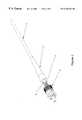
- FIG. 1shows an SC fiber optic connector having a stop ring with an outer surface designed to correspond to the inner surface of a strain relief boot;
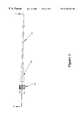
- FIG. 2shows the strengthening material of a cable positioned on the outer surface of the stop ring of the connector of FIG. 1;
- FIG. 3shows the connector assembly having the strength relief boot mated with the stop ring of the connector of FIG. 1;
- FIG. 4shows the cross section of the connector assembly of FIG. 3
- FIG. 5shows a detailed view of the cable jacket and Kevlar held between the strain relief boot and the stop ring.
- FIG. 1shows the connector employed in the method of securing a fiber optic cable to an SC fiber optic connector without using either a crimp ring, or epoxy.
- a slideable strain relief boot ( 20 ), having an inner geometry ( 21 ) that cooperates with the outer geometry ( 19 ) of the stop ring ( 18 )is placed on the outside of the fiber optic cable ( 10 ).
- the strengthening material ( 14 ) of cable ( 10 )is placed into position over the external geometry ( 19 ) of the stop ring ( 18 ) of the connector assembly ( 16 ). Additionally, the cable jacket ( 12 ) is positioned on the exterior portion of the strengthening material ( 14 ), and over the stop ring ( 18 ). The foregoing results in the strengthening material ( 14 ), as well as the cable jacket ( 12 ) conforming to the external geometry of the stop ring ( 18 ). The strengthening material ( 14 ) and the cable jacket ( 12 ) are thus in position to be engaged by the strain relief boot ( 20 ).
- the strain relief boot ( 20 )is placed over the cable jacket ( 12 ) and the strengthening material ( 14 ).
- the inner geometry ( 21 ) of the strain relief boot ( 20 )corresponds with external geometry ( 19 ) of the stop ring ( 18 ).
- the strengthening material ( 14 ) and the cable jacket ( 12 )are captured in a hazardous path between the cooperating geometries of the strain relief boot ( 20 ) and the stop ring ( 18 ), and held in place by the pressure exerted between the stain relief boot ( 20 ) and the stop ring ( 18 ).
- the claimed apparatus and methodsuccessfully accomplishes the same secured connection between a fiber optic cable and other fiber optic connector assemblies.
- the internal geometry of the strain relief bootcooperates with the external geometry of the frame A connector part.
- the internal geometry of the strain relief bootalso cooperates with the external geometry of the ferrule stem connector part in an ST connector.
Landscapes
- Physics & Mathematics (AREA)
- General Physics & Mathematics (AREA)
- Optics & Photonics (AREA)
- Mechanical Coupling Of Light Guides (AREA)
Abstract
Description
The present invention relates to a connector assembly and method for securing a fiber optic reinforced cable to a connector, more particularly, the connector may be secured to the cable without the use of either a crimp ring or epoxy. Rather the cable and connector are secured by pressure directly to each other, with the strengthening material and cable jacket between, in a hazardous path (alternate steps) using mating geometries of the strain relief boot and connector.
It is well known within the fiber optic industry to use either epoxy or crimp rings to secure a reinforced cable to fiber optic connectors. Epoxy is, however, process sensitive, messy, and of questionable reliability. The use of crimp rings adds parts, cost, and a processing step to the termination process. For these reasons the use of crimp rings is problematic.
U.S. Pat. No. 4,708,428 claims a light waveguide connector, using a hollow extension to prolong the connector body. The extension has a section with external grooves that cooperate with the internal grooves of a clamping sleeve. Prior to placing the clamping sleeve over the grooved area of the extension, the grooved area of the extension is covered with an end section of KEVLAR® fiber (KEVLAR® is a registered trademark of E.I. DuPont De Nemours) located directly under the cable jacket, and not covered by the cable jacket of the cable. The light waveguide cable is secured to the connector by engaging the KEVLAR® between the cooperating grooves of the extension, and the clamping sleeve. U.S. Pat. No. 4,707,428 does not disclose engagement of the cable jacket between the cooperating grooves of the extension and the clamping sleeve.
It is the primary objective of the present invention to provide a reliable method for securing a fiber optic cable to a connector.
It is an objective of the present invention to provide a connector assembly capable of being secured onto a cable without the use of adhesive.
Another objective of the present invention is provide a method for securing a fiber optic cable to a connector without using any type of adhesive.
Another objective of the present invention is to avoid the process sensitivity encountered with the use of adhesives, such as epoxy.
Another objective of the present invention is to avoid the messy results that accompany the use of adhesive, such as epoxy.
Another objective of the present invention is to avoid the unpredictable results often encountered with the use of adhesives, such as epoxy.
Another objective of the present invention is to avoid the use of crimping.
Another objective the present invention is to avoid the extra mechanical pails associated with crimping.
Another objective of the present invention is to avoid the excess costs associated with crimping.
Yet another objective of the present invention is to eliminate the additional process step associated with crimping.
The present invention, in contrast to U.S. Pat. No. 4,708,428, provides a connector assembly and method for attaching a fiber optic cable to the connector of the connector assembly by securing the connector and a strain relief boot directly to one another with pressure. This causes the capturing of both the KEVLAR® and the cable jacket between a hazardous path created by the mating geometries of the strain relief boot and the connector.
Additional objectives, and advantages of the present invention will become apparent to persons skilled in the art from the following detailed description.
According to the present invention, the need for either a crimp ring, or epoxy is eliminated for securing a connector to the cable. This reduction in parts or materials reduces both the pail and process costs. Additionally, elimination of epoxy use makes the process more efficient, neater, and more reliable. The invention involves securing the fiber optic cable, reinforced with KEVLAR®, onto the connector directly through the use of pressure and a hazardous path. The hazardous path results from cooperating geometries designed into the strain relief boot and the connector pall which is the stop ring in an SC connector, frame A in an FC connector, and ferrule stem in an ST connector. Both the KEVLAR® and the cable jacket are captured between the strain relief boot and the geometrically cooperating connector part. The pressure exerted by the elastomer strain relief boot forces both the cable jacket and the KEVLAR® to follow the hazardous path geometry between the parts. When an axial load is applied to the cable, the friction created by the interference points along the hazardous path sufficiently constrains the cable jacket, the KEVLAR®, and consequently, the cable from separating from the connector. A simple tool is used to push the strain relief boot onto the mating connector part. The present invention provides a connector and method for securing a cable to the connector, rendering the use of a crimp ring and epoxy unnecessary. The elimination of the crimp ring from the process results in a reduction in the number of parts needed and process costs. The elimination of epoxy results in a neater, more efficient, and more reliable process.
FIG. 1 shows an SC fiber optic connector having a stop ring with an outer surface designed to correspond to the inner surface of a strain relief boot;
FIG. 2 shows the strengthening material of a cable positioned on the outer surface of the stop ring of the connector of FIG. 1;
FIG. 3 shows the connector assembly having the strength relief boot mated with the stop ring of the connector of FIG. 1;
FIG. 4 shows the cross section of the connector assembly of FIG. 3; and
FIG. 5 shows a detailed view of the cable jacket and Kevlar held between the strain relief boot and the stop ring.
FIG. 1 shows the connector employed in the method of securing a fiber optic cable to an SC fiber optic connector without using either a crimp ring, or epoxy. A fiber optic cable (10), having a cable jacket (12), and a strengthening material (14), is supplied. A fiber optic connector assembly (16), with a stop ring (18), having an outer geometry (19), is also supplied. A slideable strain relief boot (20), having an inner geometry (21) that cooperates with the outer geometry (19) of the stop ring (18) is placed on the outside of the fiber optic cable (10).
As seen in FIG. 2, the strengthening material (14) of cable (10) is placed into position over the external geometry (19) of the stop ring (18) of the connector assembly (16). Additionally, the cable jacket (12) is positioned on the exterior portion of the strengthening material (14), and over the stop ring (18). The foregoing results in the strengthening material (14), as well as the cable jacket (12) conforming to the external geometry of the stop ring (18). The strengthening material (14) and the cable jacket (12) are thus in position to be engaged by the strain relief boot (20).
As indicated in FIGS. 3 and 4, using a simple tool, the strain relief boot (20) is placed over the cable jacket (12) and the strengthening material (14). The inner geometry (21) of the strain relief boot (20) corresponds with external geometry (19) of the stop ring (18). As a result, the strengthening material (14) and the cable jacket (12) are captured in a hazardous path between the cooperating geometries of the strain relief boot (20) and the stop ring (18), and held in place by the pressure exerted between the stain relief boot (20) and the stop ring (18). When an axial load is applied to the fiber optic cable (10), the friction created by the interference points along the hazardous path sufficiently constrains the fiber optic cable jacket (12) and the strengthening material (14) from separating from the stop ring (18), thus keeping the fiber optic cable (10) secured to the fiber optic connector assembly (16). This secured connection is illustrated in FIG.5.
It is to be appreciated that the claimed apparatus and method successfully accomplishes the same secured connection between a fiber optic cable and other fiber optic connector assemblies. For example, with an FC connector, the internal geometry of the strain relief boot cooperates with the external geometry of the frame A connector part. Additionally, the internal geometry of the strain relief boot also cooperates with the external geometry of the ferrule stem connector part in an ST connector. Although the invention has been described with respect to specific connector assemblies, the attached claims are not to be thus limited, but rather are to be construed as embodying all modifications and alternative constructions that may occur to one skilled in the art which fairly fall within the basic teaching set forth here.
Having described the presently preferred embodiments, it is to be understood that the invention may be otherwise embodied within the scope of the appended claims.
Claims (15)
1. A fiber optic connector assembly for connecting a fiber optic connector and a fiber optic cable, said cable having a cable jacket and a strengthening material, said connector assembly comprising:
a connector assembly body having an exterior surface with a geometric pattern; and
a strain relief boot having an inner surface geometrically designed to mate with said geometric pattern of said exterior surface of said connector assembly body such that when said cable is positioned so that said cable jacket and strengthening material touch and cover said exterior surface of said connector assembly body and said strain relief boot is slid over said connector assembly body, said cable jacket and said strengthening material are captured in a hazardous path formed between said mating inner surface of said strain relief boot and said exterior surface of said connector assembly body.
2. The connector assembly according toclaim 1 wherein said fiber optic connector is an SC connector.
3. The connector assembly according toclaim 2 wherein said connector assembly body is a stop ring.
4. The connector assembly according toclaim 1 wherein said fiber optic connector is an FC connector.
5. The connector assembly according toclaim 4 wherein said connector assembly body is a frame A.
6. The connector assembly according toclaim 1 wherein said fiber optic connector is an ST connector.
7. The connector assembly according toclaim 6 wherein said connector assembly body is a ferrule stem.
8. A method for securing fiber optic cable to a connector, comprising:
providing a cable, said cable having an outer surface, an end section, a cable jacket, and a strengthening material;
positioning a strain relief boot about said outer surface of said cable, said strain relief boot having an inner surface, wherein said inner surface has a first geometric patter;
providing a connector assembly, said connector assembly having a connector assembly part, a plug end, a cable end, and an exterior surface, wherein said exterior surface has a second geometric pattern which cooperates with said first geometric pattern on said inner surface of said strain relief boot, said connector part being located on said cable end;
positioning said end section of said cable in a manner such that said cable jacket and said strengthening material touch, and cover said outer surface of said connector part; and
using a simple tool to slide said strain relief boot toward said connector, and over said connector part thereby exerting pressure and causing said cable jacket and said strengthening material to be captured in a hazardous path between said first geometric pattern on inner surface of said strain relief boot, and said second geometric pattern on said exterior surface of said connector assembly part.
9. The method according toclaim 8 , said connector being an SC connector.
10. The method according toclaim 9 , said connector assembly part being a stop ring.
11. The method according toclaim 8 , said connector assembly being an FC connector.
12. The method according toclaim 11 , said connector assembly part being a frame A.
13. The method according toclaim 8 , said connector assembly being an ST connector.
14. The method according toclaim 13 , said connector assembly part being a ferrule stem.
15. A fiber optic connector assembly for connecting a fiber optic connector and a fiber optic cable, said cable having a cable jacket and a strengthening material, said connector assembly comprising:
a connector assembly body having an exterior surface with a geometric pattern; and
a strain relief boot having an inner surface geometrically designed to mate with said geometric pattern of said exterior surface of said connector assembly body such that when said cable is positioned so that said cable jacket and strengthening material touch and cover said exterior surface of said connector assembly body and said strain relief boot is slid over said connector assembly body, said cable jacket and said strengthening material are captured in a hazardous path formed between said mating inner surface of said strain relief boot and said exterior surface of said connector assembly body.
Priority Applications (1)
| Application Number | Priority Date | Filing Date | Title |
|---|---|---|---|
| US09/394,739US6340249B1 (en) | 1999-09-13 | 1999-09-13 | Connector assembly and method of securing fiber optic cable to connector |
Applications Claiming Priority (1)
| Application Number | Priority Date | Filing Date | Title |
|---|---|---|---|
| US09/394,739US6340249B1 (en) | 1999-09-13 | 1999-09-13 | Connector assembly and method of securing fiber optic cable to connector |
Publications (1)
| Publication Number | Publication Date |
|---|---|
| US6340249B1true US6340249B1 (en) | 2002-01-22 |
Family
ID=23560226
Family Applications (1)
| Application Number | Title | Priority Date | Filing Date |
|---|---|---|---|
| US09/394,739Expired - LifetimeUS6340249B1 (en) | 1999-09-13 | 1999-09-13 | Connector assembly and method of securing fiber optic cable to connector |
Country Status (1)
| Country | Link |
|---|---|
| US (1) | US6340249B1 (en) |
Cited By (18)
| Publication number | Priority date | Publication date | Assignee | Title |
|---|---|---|---|---|
| US20040008949A1 (en)* | 2002-06-21 | 2004-01-15 | Gang Liu | Fiber optic connection system and method of using the same |
| WO2008030432A3 (en)* | 2006-09-06 | 2008-06-26 | Afl Telecommunications Llc | Spliced-on connector system and method, splicer, and connector holder for producing the same |
| US20090032282A1 (en)* | 2007-08-01 | 2009-02-05 | Panduit Corp. | Cable Strain Relief Module Assembly |
| USRE43542E1 (en) | 2000-06-12 | 2012-07-24 | Adc Gmbh | Assembly and method for use in terminating an optical fiber or fibers |
| US8622481B2 (en) | 2011-01-25 | 2014-01-07 | Joy Mm Delaware, Inc. | Fiber optic cable protection in a mining system |
| US8939654B2 (en) | 2012-09-27 | 2015-01-27 | Adc Telecommunications, Inc. | Ruggedized multi-fiber fiber optic connector with sealed dust cap |
| US9016953B2 (en) | 2012-02-20 | 2015-04-28 | Adc Telecommunications, Inc. | Fiber optic connector, fiber optic connector and cable assembly, and methods for manufacturing |
| WO2015144296A1 (en)* | 2014-03-25 | 2015-10-01 | Rosenberger Hochfrequenztechnik Gmbh & Co. Kg | Cable holder arrangement |
| US9268102B2 (en) | 2012-02-07 | 2016-02-23 | Tyco Electronics Raychem Bvba | Cable termination assembly and method for connectors |
| US9304262B2 (en) | 2011-11-23 | 2016-04-05 | Commscope Technologies Llc | Multi-fiber optic connector |
| US9310572B2 (en) | 2012-10-18 | 2016-04-12 | Corning Cable Systems Llc | Cable bend relief for fiber optic sub-assemblies and methods of assembling |
| US9720185B2 (en) | 2014-05-23 | 2017-08-01 | Commscope Technologies Llc | Systems and method for processing optical cable assemblies |
| US11531168B2 (en) | 2017-06-28 | 2022-12-20 | Corning Research & Development Corporation | Fiber optic connectors having a keying structure and methods of making the same |
| US11686913B2 (en) | 2020-11-30 | 2023-06-27 | Corning Research & Development Corporation | Fiber optic cable assemblies and connector assemblies having a crimp ring and crimp body and methods of fabricating the same |
| GB2622374A (en)* | 2022-09-13 | 2024-03-20 | Oxford Fiber Ltd | Optical fibre connector |
| US12019285B2 (en) | 2020-09-30 | 2024-06-25 | Corning Research & Development Corporation | Connector assemblies for telecommunication enclosures |
| US12345927B2 (en) | 2020-11-30 | 2025-07-01 | Corning Research & Development Corporation | Fiber optic adapter assemblies including a conversion housing and a release housing |
| US12372727B2 (en) | 2020-10-30 | 2025-07-29 | Corning Research & Development Corporation | Female fiber optic connectors having a rocker latch arm and methods of making the same |
Citations (12)
| Publication number | Priority date | Publication date | Assignee | Title |
|---|---|---|---|---|
| US4607911A (en) | 1983-10-03 | 1986-08-26 | Conax Buffalo Corporation | Connector for an optical fiber having a stationary clamp engaged and operated by a rotatable member |
| US4679895A (en) | 1984-08-31 | 1987-07-14 | Amp Incorporated | Adhesiveless optical fiber connector |
| US4687288A (en) | 1985-07-19 | 1987-08-18 | Allied Corporation | Fiber optic connector with temperature compensating mechanism |
| US4708428A (en) | 1985-04-18 | 1987-11-24 | Siemens Aktiengesellschaft | Light waveguide connector |
| US5088804A (en) | 1989-07-12 | 1992-02-18 | Optical Fiber Technologies, Inc. | Method and apparatus for terminating a fiber-optic cable without adhesive |
| US5113474A (en) | 1990-03-13 | 1992-05-12 | Optical Fiber Technologies, Inc. | Method and apparatus for mechanical connector assembly |
| US5121455A (en) | 1990-09-11 | 1992-06-09 | Methode Electronics, Inc. | Fiber optic connector |
| US5140661A (en)* | 1991-08-06 | 1992-08-18 | G & H Technology, Inc. | Optical fiber terminus |
| US5208887A (en) | 1990-01-22 | 1993-05-04 | Amp Incorporated | Method and apparatus for terminating a fiber-optic cable without adhesive |
| US5276752A (en) | 1992-07-29 | 1994-01-04 | Molex Incorporated | Fiber optic connector system |
| US5499310A (en) | 1993-05-28 | 1996-03-12 | Nec Corporation | Optical fiber connector with sleeve for resiliently fitting an optical fiber thereto |
| USRE35935E (en)* | 1989-09-05 | 1998-10-27 | Labinal Components And Systems, Inc. | Fiber optic connectors |
- 1999
- 1999-09-13USUS09/394,739patent/US6340249B1/ennot_activeExpired - Lifetime
Patent Citations (12)
| Publication number | Priority date | Publication date | Assignee | Title |
|---|---|---|---|---|
| US4607911A (en) | 1983-10-03 | 1986-08-26 | Conax Buffalo Corporation | Connector for an optical fiber having a stationary clamp engaged and operated by a rotatable member |
| US4679895A (en) | 1984-08-31 | 1987-07-14 | Amp Incorporated | Adhesiveless optical fiber connector |
| US4708428A (en) | 1985-04-18 | 1987-11-24 | Siemens Aktiengesellschaft | Light waveguide connector |
| US4687288A (en) | 1985-07-19 | 1987-08-18 | Allied Corporation | Fiber optic connector with temperature compensating mechanism |
| US5088804A (en) | 1989-07-12 | 1992-02-18 | Optical Fiber Technologies, Inc. | Method and apparatus for terminating a fiber-optic cable without adhesive |
| USRE35935E (en)* | 1989-09-05 | 1998-10-27 | Labinal Components And Systems, Inc. | Fiber optic connectors |
| US5208887A (en) | 1990-01-22 | 1993-05-04 | Amp Incorporated | Method and apparatus for terminating a fiber-optic cable without adhesive |
| US5113474A (en) | 1990-03-13 | 1992-05-12 | Optical Fiber Technologies, Inc. | Method and apparatus for mechanical connector assembly |
| US5121455A (en) | 1990-09-11 | 1992-06-09 | Methode Electronics, Inc. | Fiber optic connector |
| US5140661A (en)* | 1991-08-06 | 1992-08-18 | G & H Technology, Inc. | Optical fiber terminus |
| US5276752A (en) | 1992-07-29 | 1994-01-04 | Molex Incorporated | Fiber optic connector system |
| US5499310A (en) | 1993-05-28 | 1996-03-12 | Nec Corporation | Optical fiber connector with sleeve for resiliently fitting an optical fiber thereto |
Cited By (51)
| Publication number | Priority date | Publication date | Assignee | Title |
|---|---|---|---|---|
| USRE43542E1 (en) | 2000-06-12 | 2012-07-24 | Adc Gmbh | Assembly and method for use in terminating an optical fiber or fibers |
| US20040008949A1 (en)* | 2002-06-21 | 2004-01-15 | Gang Liu | Fiber optic connection system and method of using the same |
| WO2008030432A3 (en)* | 2006-09-06 | 2008-06-26 | Afl Telecommunications Llc | Spliced-on connector system and method, splicer, and connector holder for producing the same |
| US20090162019A1 (en)* | 2006-09-06 | 2009-06-25 | Afl Telecommunications Llc | Spliced-on connector system and method, splicer, and connector holder for producing the same |
| US8043013B2 (en) | 2006-09-06 | 2011-10-25 | Afl Telecommunications Llc | Spliced-on connector system and method, splicer, and connector holder for producing the same |
| US20090032282A1 (en)* | 2007-08-01 | 2009-02-05 | Panduit Corp. | Cable Strain Relief Module Assembly |
| US8039745B2 (en) | 2007-08-01 | 2011-10-18 | Panduit Corp. | Cable strain relief module assembly |
| US8950822B2 (en) | 2011-01-25 | 2015-02-10 | Joy Mm Delaware, Inc. | Fiber optic cable protection in a mining system |
| US8622481B2 (en) | 2011-01-25 | 2014-01-07 | Joy Mm Delaware, Inc. | Fiber optic cable protection in a mining system |
| US12019282B2 (en) | 2011-11-23 | 2024-06-25 | Commscope Technologies Llc | Multi-fiber fiber optic connector |
| US9964715B2 (en) | 2011-11-23 | 2018-05-08 | Commscope Technologies Llc | Multi-fiber fiber optic connector |
| US11237331B2 (en) | 2011-11-23 | 2022-02-01 | Commscope Technologies Llc | Multi-fiber fiber optic connector |
| US10451817B2 (en) | 2011-11-23 | 2019-10-22 | Commscope Technologies Llc | Multi-fiber fiber optic connector |
| US10782487B2 (en) | 2011-11-23 | 2020-09-22 | Commscope Technologies Llc | Multi-fiber fiber optic connector |
| US9304262B2 (en) | 2011-11-23 | 2016-04-05 | Commscope Technologies Llc | Multi-fiber optic connector |
| US9864151B2 (en) | 2011-11-23 | 2018-01-09 | CommScope Technologies LCC | Multi-fiber fiber optic connector |
| US9442257B2 (en) | 2011-11-23 | 2016-09-13 | Commscope Technologies Llc | Multi-fiber fiber optic connector |
| US9268102B2 (en) | 2012-02-07 | 2016-02-23 | Tyco Electronics Raychem Bvba | Cable termination assembly and method for connectors |
| US9625660B2 (en) | 2012-02-07 | 2017-04-18 | CommScope Connectivity Belgium BVBA | Cable termination assembly and method for connectors |
| US10036859B2 (en) | 2012-02-07 | 2018-07-31 | CommScope Connectivity Belgium BVBA | Cable termination assembly and method for connectors |
| US9470850B2 (en) | 2012-02-20 | 2016-10-18 | Commscope Technologies Llc | Fiber optic connector, fiber optic connector and cable assembly, and methods for manufacturing |
| US11125951B2 (en) | 2012-02-20 | 2021-09-21 | Commscope Technologies Llc | Fiber optic connector, fiber optic connector and cable assembly, and methods for manufacturing |
| US9016953B2 (en) | 2012-02-20 | 2015-04-28 | Adc Telecommunications, Inc. | Fiber optic connector, fiber optic connector and cable assembly, and methods for manufacturing |
| US10353154B2 (en) | 2012-02-20 | 2019-07-16 | Commscope Technologies Llc | Fiber optic connector, fiber optic connector and cable assembly, and methods for manufacturing |
| US9291780B2 (en) | 2012-09-27 | 2016-03-22 | Commscope Technologies Llc | Ruggedized multi-fiber fiber optic connector with sealed dust cap |
| US8939654B2 (en) | 2012-09-27 | 2015-01-27 | Adc Telecommunications, Inc. | Ruggedized multi-fiber fiber optic connector with sealed dust cap |
| US9310572B2 (en) | 2012-10-18 | 2016-04-12 | Corning Cable Systems Llc | Cable bend relief for fiber optic sub-assemblies and methods of assembling |
| TWI683492B (en)* | 2014-03-25 | 2020-01-21 | 羅森伯格高頻技術公司 | Cable structure |
| WO2015144296A1 (en)* | 2014-03-25 | 2015-10-01 | Rosenberger Hochfrequenztechnik Gmbh & Co. Kg | Cable holder arrangement |
| US9720185B2 (en) | 2014-05-23 | 2017-08-01 | Commscope Technologies Llc | Systems and method for processing optical cable assemblies |
| US12013578B2 (en) | 2017-06-28 | 2024-06-18 | Corning Research & Development Corporation | Multifiber fiber optic connectors, cable assemblies and methods of making the same |
| US12174432B2 (en) | 2017-06-28 | 2024-12-24 | Corning Research & Development Corporation | Fiber optic connectors and connectorization employing adhesive admitting adapters |
| US12429655B2 (en) | 2017-06-28 | 2025-09-30 | Corning Optical Communications LLC | Multiports having connection ports with associated securing features and methods of making the same |
| US11906792B2 (en) | 2017-06-28 | 2024-02-20 | Corning Research & Development Corporation | Compact fiber optic connectors having multiple connector footprints, along with cable assemblies and methods of making the same |
| US11914198B2 (en) | 2017-06-28 | 2024-02-27 | Corning Research & Development Corporation | Compact fiber optic connectors having multiple connector footprints, along with cable assemblies and methods of making the same |
| US12379552B2 (en) | 2017-06-28 | 2025-08-05 | Corning Research & Development Corporation | Compact fiber optic connectors, cable assemblies and methods of making the same |
| US11940656B2 (en) | 2017-06-28 | 2024-03-26 | Corning Research & Development Corporation | Compact fiber optic connectors, cable assemblies and methods of making the same |
| US11543600B2 (en) | 2017-06-28 | 2023-01-03 | Corning Research & Development Corporation | Compact fiber optic connectors having multiple connector footprints, along with cable assemblies and methods of making the same |
| US11531168B2 (en) | 2017-06-28 | 2022-12-20 | Corning Research & Development Corporation | Fiber optic connectors having a keying structure and methods of making the same |
| US12379551B2 (en) | 2017-06-28 | 2025-08-05 | Corning Optical Communications LLC | Multiports having connection ports formed in the shell and associated securing features |
| US12092878B2 (en) | 2017-06-28 | 2024-09-17 | Corning Research & Development Corporation | Fiber optic connectors having a keying structure and methods of making the same |
| US11579377B2 (en) | 2017-06-28 | 2023-02-14 | Corning Research & Development Corporation | Compact fiber optic connectors, cable assemblies and methods of making the same with alignment elements |
| US12276846B2 (en) | 2017-06-28 | 2025-04-15 | Corning Research & Development Corporation | Compact fiber optic connectors, cable assemblies and methods of making the same |
| US12298568B2 (en) | 2017-06-28 | 2025-05-13 | Corning Research & Development Corporation | Fiber optic connectors and multiport assemblies including retention features |
| US12353025B2 (en) | 2017-06-28 | 2025-07-08 | Corning Optical Communications LLC | Multiports having a connection port insert and methods of making the same |
| US12353024B2 (en) | 2017-06-28 | 2025-07-08 | Corning Research & Development Corporation | Multiports and optical connectors with rotationally discrete locking and keying features |
| US12019285B2 (en) | 2020-09-30 | 2024-06-25 | Corning Research & Development Corporation | Connector assemblies for telecommunication enclosures |
| US12372727B2 (en) | 2020-10-30 | 2025-07-29 | Corning Research & Development Corporation | Female fiber optic connectors having a rocker latch arm and methods of making the same |
| US12345927B2 (en) | 2020-11-30 | 2025-07-01 | Corning Research & Development Corporation | Fiber optic adapter assemblies including a conversion housing and a release housing |
| US11686913B2 (en) | 2020-11-30 | 2023-06-27 | Corning Research & Development Corporation | Fiber optic cable assemblies and connector assemblies having a crimp ring and crimp body and methods of fabricating the same |
| GB2622374A (en)* | 2022-09-13 | 2024-03-20 | Oxford Fiber Ltd | Optical fibre connector |
Similar Documents
| Publication | Publication Date | Title |
|---|---|---|
| US6340249B1 (en) | Connector assembly and method of securing fiber optic cable to connector | |
| CA2221840C (en) | Method and structure for connecting ribbon cord to a connector | |
| EP0862072A2 (en) | Clamp rings and optical fibre terminating structures | |
| US4795229A (en) | Strain relief assembly for optical fiber connector | |
| US4336977A (en) | Crimped connector assembly for fiber optic cables | |
| EP0048561B1 (en) | An optical waveguide connector assembly | |
| EP0192735B1 (en) | A connector for an optical fiber | |
| CN1054919C (en) | Pull-proof, modular fiber optic connector system | |
| EP1258758A2 (en) | Fiber optic module attachment including a fiber locating connector | |
| JPH0777630A (en) | Optical fiber connector | |
| JPH0473125B2 (en) | ||
| US20090304335A1 (en) | Hardened Fiber Optic Connector with Connector Body Joined to Cylindrical Cable by Unitary Housing | |
| EP0924800A3 (en) | Crimpable connector for coaxial cable | |
| EP1959282A3 (en) | Fiber optic drop cables and preconnectorized assemblies having toning portions | |
| US4730890A (en) | Plug set for optical connector for optical fiber cables | |
| EP1148364A3 (en) | Strain relief clamping mechanism for an optical fiber connector | |
| JP2000241662A (en) | Optical connector and method of manufacturing optical connector | |
| US6302594B1 (en) | Optical fiber connections | |
| US5455880A (en) | Optical fiber cable connector assembly | |
| US11086090B2 (en) | Cable fixing apparatus, cable connector and electrical device | |
| CA1266580A (en) | Fiber optic connector backshell | |
| US6196731B1 (en) | Quick-connect fiber optic connector | |
| AU2005208077B2 (en) | A crimp for an optical cable connector | |
| US10481343B2 (en) | Fiber optic drop cable assembly and preconnectorized cable assembly | |
| GB2031605A (en) | Crimped connector assembly for fiber optic cables or the like |
Legal Events
| Date | Code | Title | Description |
|---|---|---|---|
| AS | Assignment | Owner name:ALCOA FUJIKURA LTD., TENNESSEE Free format text:ASSIGNMENT OF ASSIGNORS INTEREST;ASSIGNORS:HAYES, EARL J.;HALL, THOMAS A., III;WANG, BO M.;REEL/FRAME:010398/0684;SIGNING DATES FROM 19990921 TO 19991108 | |
| STCF | Information on status: patent grant | Free format text:PATENTED CASE | |
| FPAY | Fee payment | Year of fee payment:4 | |
| AS | Assignment | Owner name:AFL TELECOMMUNICATIONS LLC, TENNESSEE Free format text:ASSIGNMENT OF ASSIGNORS INTEREST;ASSIGNOR:ALCOA FUJIKURA LIMITED;REEL/FRAME:017045/0733 Effective date:20051110 Owner name:AFL TELECOMMUNICATIONS LLC, TENNESSEE Free format text:ASSIGNMENT OF ASSIGNORS INTEREST;ASSIGNOR:ALCOA FUJIKURA LIMITED;REEL/FRAME:017198/0463 Effective date:20051110 | |
| FPAY | Fee payment | Year of fee payment:8 | |
| FPAY | Fee payment | Year of fee payment:12 |