US6340119B2 - Techniques for reading two dimensional code, including MaxiCode - Google Patents
Techniques for reading two dimensional code, including MaxiCodeDownload PDFInfo
- Publication number
- US6340119B2 US6340119B2US09/816,173US81617301AUS6340119B2US 6340119 B2US6340119 B2US 6340119B2US 81617301 AUS81617301 AUS 81617301AUS 6340119 B2US6340119 B2US 6340119B2
- Authority
- US
- United States
- Prior art keywords
- maxicode
- symbol
- modules
- grid
- code
- Prior art date
- Legal status (The legal status is an assumption and is not a legal conclusion. Google has not performed a legal analysis and makes no representation as to the accuracy of the status listed.)
- Expired - Lifetime
Links
Images


Classifications
- G—PHYSICS
- G06—COMPUTING OR CALCULATING; COUNTING
- G06K—GRAPHICAL DATA READING; PRESENTATION OF DATA; RECORD CARRIERS; HANDLING RECORD CARRIERS
- G06K7/00—Methods or arrangements for sensing record carriers, e.g. for reading patterns
- G06K7/10—Methods or arrangements for sensing record carriers, e.g. for reading patterns by electromagnetic radiation, e.g. optical sensing; by corpuscular radiation
- G06K7/14—Methods or arrangements for sensing record carriers, e.g. for reading patterns by electromagnetic radiation, e.g. optical sensing; by corpuscular radiation using light without selection of wavelength, e.g. sensing reflected white light
- G06K7/1404—Methods for optical code recognition
- G06K7/1439—Methods for optical code recognition including a method step for retrieval of the optical code
- G06K7/1443—Methods for optical code recognition including a method step for retrieval of the optical code locating of the code in an image
- G—PHYSICS
- G06—COMPUTING OR CALCULATING; COUNTING
- G06K—GRAPHICAL DATA READING; PRESENTATION OF DATA; RECORD CARRIERS; HANDLING RECORD CARRIERS
- G06K7/00—Methods or arrangements for sensing record carriers, e.g. for reading patterns
- G06K7/10—Methods or arrangements for sensing record carriers, e.g. for reading patterns by electromagnetic radiation, e.g. optical sensing; by corpuscular radiation
- G06K7/14—Methods or arrangements for sensing record carriers, e.g. for reading patterns by electromagnetic radiation, e.g. optical sensing; by corpuscular radiation using light without selection of wavelength, e.g. sensing reflected white light
- G06K7/1404—Methods for optical code recognition
- G06K7/1439—Methods for optical code recognition including a method step for retrieval of the optical code
- G06K7/1456—Methods for optical code recognition including a method step for retrieval of the optical code determining the orientation of the optical code with respect to the reader and correcting therefore
Definitions
- the inventionrelates to techniques for reading two dimensional code such as MaxiCode. Aspects of the invention are particularly useful in imaging optical code readers which are designed to read various kinds of optical code.
- Optical codesare patterns made up of image areas having different light reflective or light emissive properties, which are typically assembled in accordance with a priori rules.
- the term “bar code”is sometimes used to describe certain kinds of optical codes.
- the optical properties and patterns of optical codesare selected to distinguish them in appearance from the background environments in which they are used.
- Devices for identifying or extracting data from optical codesare sometimes referred to as “optical code readers” of which bar code scanners are one type.
- Optical code readersare used in both fixed or portable installations in many diverse environments such as in stores for check-out services, in manufacturing locations for work flow and inventory control and in transport vehicles for tracking package handling.
- the optical codecan be used as a rapid, generalized means of data entry, for example, by reading a target bar code from a printed listing of many bar codes.
- the optical code readeris connected to a portable data processing device or a data collection and transmission device.
- the optical code readerincludes a handheld sensor which is manually directed at a target code.
- the bar codeis a pattern of variable-width rectangular bars separated by fixed or variable width spaces. The bars and spaces have different light reflecting characteristics.
- One example of a one dimensional bar codeis the UPC/EAN code used to identify, for example, product inventory.
- An example of a two dimensional or stacked bar codeis the PDF417 bar code.
- a description of PDF417 bar code and techniques for decoding itare disclosed in U.S. Pat. No. 5,635,697 to Shellhammer et al. and assigned to Symbol Technologies, Inc., which patent is incorporated herein by reference.
- Conventional codesare known which are based on a two dimensional grid whose geometry is independent of data content.
- the gridmay be a plane tiled by regular polygons such as squares or hexagons.
- regular polygonssuch as squares or hexagons.
- a black or white feature or polygonis located at each grid location.
- MaxiCodeis a matrix symbology made up of offset rows of hexagonal modules arranged around a finder pattern.
- a MaxiCode symbolmay consist of a unique central finder pattern: up to 3 dark concentric rings and 3 included light areas, sometimes called a “bulls-eye”.
- the central finder patternis surrounded by an approximately square-shaped array of 33 offset rows of hexagonal modules.
- the 33 rows in the symbolalternate between 30 and 29 modules in width.
- Orientation information (rotation)is provided by 6 patterns of three modules each located adjacent to the bulls-eye. Data is carried in the presence or absence of darkened modules within the hexagonal grid.
- a binary encoding schememay be used to represent information in black (low reflectivity) and white (high reflectivity). MaxiCode is described in detail in the publication “International Symbology Specification—MaxiCode”, by AIM International, Inc. (hereinafter “AIM Specification”).
- an image sensormay be employed which has a two dimensional array of cells or photo sensors which correspond to image elements or pixels in a field of view of the device.
- Such an image sensormay be a two dimensional or area charge coupled device (CCD) and associated circuits for producing electronic signals corresponding to a two dimensional array of pixel information for a field of view.
- CCDarea charge coupled device
- An imaging engine usable in reading MaxiCodeis disclosed in U.S. patent application Ser. No. 09/096,578 filed Jun. 12, 1998, entitled IMAGING ENGINE AND METHOD FOR CODE READERS to Correa et al. which is hereby incorporated by reference. Electronic circuits in or associated with the imaging engine may be provided to decode MaxiCode.
- the above-mentioned AIM Specificationdiscloses a frequency—domain technique to decode MaxiCode.
- three principal MaxiCode axesassumed to correspond to the hexagon grid, are found in two dimensional pixel data using a Fourier transform technique.
- Grid locations for the modulesare then determined by use of inverse Fourier transform techniques.
- such techniquesrequire computationally intensive, two dimensional transforms, which have long processing times particularly at high resolution levels preferred for accurate decoding.
- such techniquesmay not accurately accommodate tilted or warped MaxiCode symbols.
- MaxiCodeis a type of matrix code which lacks extensive self-synchronization such as that built into PDF417. Some variants of Data Matrix also fall into this category. To decode such types of two dimensional bar codes, a projection or interpolation based on a single line or even a few lines is not adequate and could result in module displacement.
- the disclosurerelates to techniques for determining the presence, orientation and location of features in an image of a two dimensional optical code especially grid-based codes whose geometry is independent of data content, and more especially grid-based code based on repeating non-rectangular module shapes such as hexagons.
- the techniquesare adapted for use in locating finder patterns and orientation modules, and in mapping data in an image pixel plane with grid locations in a grid-based two dimensional code to account for size, rotation, tilt, warping and distortion of the code symbol.
- a codeis a MaxiCode
- techniquesare disclosed for determining the presence and location of the MaxiCode bulls-eye and orientation modules.
- a preferred embodiment of the present inventionis a method for determining the presence and location of a MaxiCode symbol bulls-eye and the orientation of the symbol in pixel data obtained by an optical code reader.
- a candidate center in a run of pixels having a color indicative of the center area of the bulls-eyeis identified.
- the candidate centeris tested to determine if adjacent pixel runs have a predetermined amount of mirror symmetry with respect to the candidate center.
- Plural pointsare located on axes radiating from the identified run and intersecting an edge of a ring of the MaxiCode bulls-eye.
- An ellipseis fitted to the located points and the ellipse is expanded outwardly to estimate the location of orientation modules of the MaxiCode.
- the orientation of the MaxiCode symbolis determined from information read from the orientation modules.
- the fitted ellipsemay be required to have major and minor dimensions having a ratio of 2:1 or less. If this ratio is not met, the image may be rejected as exhibiting too great a tilt.
- a least squares fitmay be employed to find the major and minor dimensions of the ellipse fitted to the located points.
- the ring edge located and fittedis the inner edge of the outermost black ring of the MaxiCode bulls-eye. Up to 24 points may be used in the least square fit to find the major and minor dimensions of the ellipse.
- Another preferred embodiment of the present inventionincludes techniques for associating pixel data in a pixel plane of a two dimensional grid-based symbol with corresponding modules in the grid.
- subsets of the pixel data having a known association with plural seed modulessuch as MaxiCode orientation modules, are identified.
- the coefficients of an Euler transformare determined through a least-squared best-fit method using the identified association between the pixel data subsets and the seed modules. Using the Euler transform, other locations in the pixel plane are associated with additional symbol modules.
- the seed modulesmay be a selected subset of the 18 orientation hexagon modules of the MaxiCode symbol, preferably as many of such modules whose locations are readily distinguishable.
- the techniqueis usable, for example, where the grid-based symbol is not located in any single plane perpendicular to the optical axis of the optical code reader, such as where the symbol lies on a tilted plane or is printed on the curved face of a can.
- a methodfor decoding a MaxiCode symbol to obtain data from the primary data modules and secondary data modules located on the hexagonal grid.
- the central finder patternis located and then the orientation modules located based on the location of the central finder pattern.
- the location of primary data modules of the MaxiCodeare found based on the previously determined locations of the orientation modules.
- the secondary data modulesare sequentially locating outwardly from the primary message modules toward the edge of the symbol using previously located positions of adjacent modules. Secondary data modules are located in a successive radial progression of rings of hexagons outward toward the edges of the symbol.
- the location of secondary data modulesare estimated using the positions of adjacent modules and just past adjacent modules.
- the location of a first set of secondary data modulesmay be refined by centering black/white transitions before locating a next set of secondary data modules further outward for the central finder pattern. Deviations from a regular hexagonal grid are accumulated as the location of secondary data modules proceeds outwardly from the central finder pattern.
- the initial location of the central finder patternmay be based on finding a candidate bulls-eye center by testing local symmetry about selected axes.
- a candidate sequence of alternating runs running in a horizontal direction (with respect to the image detector)may be tested, the 5 th run being the candidate center run.
- the candidate sequenceis evaluated to verify that the lengths of the runs are within a predetermined proportion of a selected one of the runs.
- a candidate centermay be further tested by evaluating pixel data vertically above and below the candidate center for approximate mirror symmetry in the location of corresponding black/white transitions in the data.
- horizontal and vertical distancesmay be subjected to a ratio test to evaluate the image.
- further testing of a candidate centermay be done by evaluating pixel data on diagonal lines passing through the candidate center for appropriate mirror symmetry in the location of corresponding black/white transitions in the data. If all tests are passed, the candidate center and/or black/white transition data may be used to locate additional features of the MaxiCode.
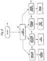
- FIG. 1is a block diagram of various electronic circuits employed in a preferred embodiment of the present invention
- FIG. 2is a combined flow chart and system block diagram illustrating the preprocessing and decoding of CCD data in a preferred embodiment of the present invention
- FIG. 3is a flow chart illustrating the reading and translating of two dimensional, image data identified by preprocessing as corresponding to a MaxiCode symbol
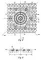
- FIG. 4is a plan view of a portion of the arrangement of a conventional MaxiCode symbol, with the addition of reference axes;
- FIG. 5is an example of pixel runs used in a preferred embodiment of the present invention.
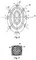
- FIG. 6is a detail of an image of a central finder or bulls-eye of a MaxiCode symbol showing the location of ellipse fitting points in accordance with a preferred embodiment of the present invention
- FIG. 7illustrates aspects of the present invention related to determining the rotation or orientation of a MaxiCode symbol
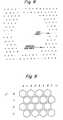
- FIG. 8is an illustration of grid points generated to correspond to a MaxiCode symbol in accordance with a preferred embodiment of the present invention.
- FIG. 9is an illustration of a hexagonal grid with indexing numbers (i, j).
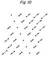
- FIG. 10illustrates a vector field usable in the present invention to correct distortions of image data of a two dimensional code symbol.
- FIG. 1is a block diagram of various electronic circuits employed in preferred embodiments of the present invention.
- An image sensor 2has an optical axis 3 .
- An imageis obtained of a symbol, shown located on an arbitrary warped and tilted surface 5 (not in a plane and not perpendicular to the optical axis 3 ).
- electronic signals from the image sensor 2pass to FPGA (or ASIC) circuit 4 .
- the image sensor 2includes a CCD detector and various signal conditioning circuits which produce a digital output signal.
- This digital output signalmay be in the form of electronic signals corresponding to a two dimensional array of pixel information for a target field of view.
- Digital signals from the imaging sensorare supplied to the microprocessor 6 by the FPGA circuit 4 .
- the FPGAalso provides control signals from the microprocessor for control of, for example, the aiming systems, illumination systems and objective lens servo systems of the imaging engine.
- the microprocessoralso provides information to external systems via the RS 232 driver 10 . This may include data decoded in accordance with the techniques described below.
- the micro-processormay also communicate by data line to Flash memory 12 and DRAM 14 on which software and data for the system are stored, respectively.
- This stored informationmay include data from a target optical code.
- FIG. 2is a combined flow chart and system block diagram illustrating autodiscrimination of image sensor data.
- Data obtained by the image sensor circuitryis indicated at 100.
- This datamay be in the form of electronic signals corresponding to a two dimensional array of pixel information for a target image.
- the datamay be stored for subsequent processing in the DRAM of the optical code reader.
- the processing softwarewhich implements the processes of the present disclosure may have access to the stored image data at all levels. At various processing steps, portions of the pixel data may be called up for further processing or to confirm on-going analyses.
- the pixel datamay be divided into subimages, for example, 32 ⁇ 32 pixel subimages. These subimages are analyzed for properties known to be associated with various types of optical codes and known to distinguish a particular code from other codes and environmental (non-code) images. More particularly, a process of statistical Autodiscrimination may be employed. In statistical Autodiscrimination the image is divided into sub-images or sections and some statistic computed for each section. Subimages with similar statistics can be grouped to form regions of interest or clusters which may contain codes. The advantage of the statistical approach is that once the statistics are compiled, only the sub-images need to be processed, significantly reducing the computation requirements. In addition, the compilation of the statistics is simple and can be done in hardware for super fast systems.
- the statistic used in preferred embodimentsis a histogram of local surface orientations.
- the statisticscan be obtained by analyzing surface tangents to cluster the subimages. Once a cluster is identified, the image data may be further analyzed to detect the presence of tangents associated with particular types of optical codes.
- Statistical Autodiscriminationis a subject of a U.S. patent application Ser. No. 09/096,348 entitled AUTODISCRIMINATION AND LINE DRAWING TECHNIQUES FOR CODE READERS and assigned to Symbol Technologies, Inc., which application is hereby incorporated by reference.
- a neural networkcan be used to discriminate image areas of possible interest as containing optical code.
- a neural networkcan also be designed to look directly at the input image.
- the location of the aiming pattern with respect to the subimagesmay also be used as an indicia or weighting factor in selecting subimages for further processing.
- Autodiscrimination software executed by the system microprocessordetermines which subimage clusters contain codes of a particular type and the coordinates in the pixel data array of certain boundaries or features of preliminarily identified code areas.
- This systemis indicated at 102 .
- the image datamay be preliminarily identified as a one dimensional code, two dimensional code (PDF), Postal Code or MaxiCode, it being understood that other code types with recognizable statistical or contrast patterns could be identified at this stage of processing. This preliminary identification is used to select the appropriate decoding techniques.
- the autodiscrimination functionalso passes information about the image useful in decoding. This information is shown in data windows 104 through 110 in FIG. 2 .
- Data window 110corresponds to MaxiCode data used in decoding: location information concerning one or more clusters of subimages preliminarily identified by the Autodiscrimination function as containing MaxiCode.
- FIG. 3is a flow chart illustrating the processing and decoding of two dimensional pixel data identified by the Autodiscrimination function 102 . This identification is based on the fact that the Autodiscrimination function has found within an image cluster a contrast variation within predetermined limits, but no threshold groupings of surface tangents which would be indicative of other codes having generally orthogonal feature edges such as one dimensional code, postal code or PDF code. In the processing of FIG. 3, cluster data may be accepted line by line.
- the techniqueattempts to locate a MaxiCode bulls-eye at 150 by analyzing the pixel data for patterns indicative of concentric rings. An ellipse may then be fitted to the inside edge of the outermost black ring at 152 . The rotation of the grid is determined from the location of the 18 orientation hexagons in the image as indicated at 154 . A transformation is calculated to account for scale and tilt of the target code and to map a grid, at processing step 156 . Grid locations are adapted progressively outwardly by shifting hexagon centers to better fit the pixel data, as indicated at block 158 . The result of this processing is indexed presence/absence data for the hexagonal MaxiCode grid. This data is passed to the MaxiCode translating function at 160 . If the MaxiCode decoding or translating fails during the processing of FIG. 3, process control may be returned to the Autodiscrimination function 102 to select another code type and/or cluster of subimage pixels for analysis.
- FIG. 4illustrates the arrangement of features in a portion of the MaxiCode symbol.
- a code “symbol”refers to an optical code printed or otherwise presented to view and having variable light reflectivity capable of being detected by a code reader.
- a “MaxiCode symbol”refers to a symbol having a central finder pattern and data carried in the presence or absence of darker modules arranged in a hexagonal grid surrounding the finder pattern. Examples of such MaxiCode symbols are described in the AIM Specification.
- the central finder pattern (bulls-eye) 200is first located.
- this processproceeds as follows.
- a linked list of subimages or clusteris identified by the Autodiscrimination function. Within this identified area, each horizontal line is converted into run lengths.
- a moving window averaging techniqueis used to generate an estimated grey scale threshold to determine the color of the center pixel in the window. Alternatively, the threshold may be generated in the previously preformed subimage processing.
- Each higher reflectance (white) runis tentatively treated as if it were in the white center circle 202 of a bulls-eye.
- a runis a string of two or more adjacent pixels each indicating a reflectance from the symbol either above or below a threshold value. For example, runs of from 2 to 30 white pixels may be treated as candidate center runs. Four adjacent runs of alternating color are examined on either side of the candidate center. According to the context, the word “color” is used to indicate the grey scale value of one or more pixels or a determination that a run or area of the image is black or white. The widths of corresponding pairs of runs are compared to determine whether they are too big or too small in relation to one another.
- the thresholds for rejectionare tunable parameters based on the optical characteristic of the system. Processing is expedited by noting a bad run size as it is collected and preventing further analysis as long as this run is in the current window.
- the line of black and white dots 250corresponds to a window of pixels from a horizontal row of pixels in an image cluster identified by the Autodiscrimination function as possibly containing the image of a MaxiCode symbol.
- the four central pixelshave been identified as a candidate center run.
- Four adjacent runs on the left side L 1 , L 2 , D 1 , D 2 and on right side L′ 1 , L′ 2 , D′ 1 , D′ 2 corresponding to black and white pixels (differentiated Light and Dark grey scale values)have been determined to have lengths falling within tunable parameters of the system.
- each of corresponding runs on the left and right side of the candidate centerhave equal widths, i.e. they are exactly mirror symmetric about the candidate center C.
- a cumulative radius from the candidate center of the bulls-eyeis calculated.
- the left and right cumulative radiimust be approximately symmetric. If the mismatch of the radii exceeds a predetermined threshold (e.g. a ratio of 2:1), the candidate center is rejected.
- This operationis illustrated in the example of FIG. 5 .
- the systemcompares the left radius R L and right radius R R (the distances in the pixel plane from the candidate center C to the posited inner edge 252 of the third black ring). In the example these distances are equal, therefore, the candidate center would not be rejected at this stage of processing, but would be further examined.
- a set of vertical run lengthsis generated using the same technique. This process works from the center out, however, and stops when five black/white or white/black transitions have been seen above and below the candidate center.
- This set of runsis subjected to the same symmetry and min/max run size tests listed above. If the vertical run passes, a further test is made—the ratio of the horizontal to vertical sizes must be between 1:2 and 2:1. Ratios outside this would indicate a symbol tilt exceeding 60 degrees, and, thus, would not represent a good candidate image for decoding. If both the horizontal and vertical tests are passed, a pair of diagonal runs are also tested. Each diagonal run must individually pass the run length min/max test and the symmetry test and the pair must meet the 1:2-2:1 test.
- the initial location of the central finder patternmay be based on finding a candidate center using the following steps:
- each runis between half and twice the length of the first run
- each runis between 1 and 30 pixels in length.
- step (c)examining a vertical sequence of pixels running on a vertical axis passing through the candidate center found in step (b) and evaluating whether the four adjacent runs above the candidate center run and the four adjacent runs located below the candidate center run are between half and twice the length of the run of the candidate center;
- step (f)examining a new horizontal sequence of pixels running through the new candidate center and evaluating the run lengths as in step (c) to determine whether they have the required proportionality;
- step (g)examining pixels sequences lying on two different diagonal scan lines passing through the new horizontal sequence of pixels, and evaluating the runs lengths as in step (c) to determine whether they have the required proportionality;
- FIG. 6illustrates some of the geometry of these tests.
- the Figureshows the projection in the image plane of a portion of a MaxiCode bulls-eye lying in a plane tilted with respect to the optical axis of the image sensor.
- Horizontal and vertical axes passing near or through the candidate center runare identified by numerals 260 and 262 , respectively.
- the line ⁇ overscore (HH) ⁇ ′lies on a horizontal run and the line ⁇ overscore (VV) ⁇ ′ lies on a vertical run.
- the length of the linesmay be compared to determine whether they exceed a 2:1 ratio.
- Axes 264 and 266lie on diagonal runs which may also be tested as discussed above.
- V 2⁇ S 22 ⁇ 1 ⁇ S 12 T ⁇ V 1
- the components of the two vectorsare the coefficients for the ellipse equation
- V 1( A B C ) 1
- V L( D E F ) 2
- the processingproceeds to find the orientation of the symbol.
- the ellipse calculated aboveis expanded outward from the center to the three radii corresponding to estimated radial distances of the center of the 18 orientation hexagons in the symbol.
- the 18 orientation hexagonsare arranged in six groups 214 as shown in FIG. 4 .
- the three radii 300 , 302 and 304are shown in FIG. 7 for the simplest case where the image of the bulls-eye is found to be essentially circular (an ellipse with zero eccentricity).
- a set of 360 samplesis taken along each ellipse (each circle in the case of the image of FIG. 7 ), one per degree of rotation around the ellipse.
- a correlated searchis performed for the orientation markers.
- the rotation(s) at which the maximum number of the orientation hexes is matchedis noted. If a continuous set of angles (e.g. from 18-21 degrees) all match the same set of hexes, the center of this range is used to try to locate the center of the orientation hexes if possible. This allows the calculation of the best known position of each of the 18 hexes.
- the hexagon locationsare refined by shifting the computed centers to center the internal black-to-white transitions among the hexagons, as well as a black-to-white transition toward the center of the bulls-eye.
- step (iii)If step (ii) yields a proper color match, the triplet is subjected to the same refinement procedure as in (i).
- the hexagonal gridmay be mapped.
- a best-fitted grid technique for doing thiswill now be described, it being understood that alternative techniques such as a bilinear transformation could be used to map the grid using image data from the bulls-eye.
- these equationscan be used to map a set of indices (i, j) specifying a module in a two dimensional code of interest with the module's coordinate (x, y) in the image or pixel plane.
- indicesi, j
- FIG. 8A drawing with a grid generated as such is shown in FIG. 8 .
- Processingmay then proceed to decode the primary message of the MaxiCode.
- the primary messageincludes 20 symbol characters designated 1 - 20 in FIG. 4 and including 120 modules. Symbol characters 1 - 10 are used to encode data; symbol characters 11 - 20 are used for error correction. Decoding the primary message may proceed as follows:
- the positions of the centers of the hexagonscan be corrected. This is done by finding internal black-to-white transitions in the EEC-corrected data, and then shifting the hex centers in the image to place the transitions found in the image at a position centered between the hex centers. Note that one easy way to do this is to perturb the orientation hexagons, since shifts in their locations will shift the hex centers in proper, correlated fashion.
- mappingproceeds outwardly from the primary message hexagons into the surrounding hexagons, ring by ring i.e. a radial progression from the center of the symbol.
- Each hexagon in the surrounding areacan be estimated by at least two independent methods using hexagons that are adjacent to it and just past adjacent to it. These two results can be averaged to correct for rounding errors.
- the colors (grey scale values) on either sidecan be examined to produce a local black-white threshold, allowing for changes in illumination across the image.
- Black hexagonsespecially if in white neighborhood, can be located more exactly. This property may be exploited to provide a vector field for tweaking the grid.
- a smooth, unidirectional vector fieldwhich is zero at the bulls-eye is shown in FIG. 10 .
- such a vector fieldcould be used to correct distortions caused by cylindrical warp of the symbol.
- the orientation hexagon locationscould be refined to properly center black-white transitions found in the image before the ECC is run.
- the ECCis run first. If it succeeds, the system obtains better information about what it should be seeing and computation is reduced in most cases. However, if the ECC fails, refinement to center the black-white transitions could then be attempted and the ECC process tried again. Similarly, additional passes through the secondary message might be desirable if its ECC process fails.
- the sampling gridcould be warped somewhat and the secondary message hex locations recalculated to try to achieve a successful decode. Again, a possible metric to use would be to have edge locations centered between hex centers.
- the secondary message ECC processis run.
- the resultis indexed presence/absence data for some or all of the MaxiCode grid. This data is translated to deliver the informational content of the symbol.
- translated datamay be obtained from signals corresponding to a two dimensional array of pixel information from a field of view containing the image of a MaxiCode symbol.
- the disclosed techniquesare designed to automatically adjust for image size, and tolerate as much as 60° tilt, 360° of rotation and significant warping (hexagon distance change of 50% or more).
Landscapes
- Physics & Mathematics (AREA)
- Engineering & Computer Science (AREA)
- Health & Medical Sciences (AREA)
- Electromagnetism (AREA)
- General Health & Medical Sciences (AREA)
- Toxicology (AREA)
- Artificial Intelligence (AREA)
- Computer Vision & Pattern Recognition (AREA)
- General Physics & Mathematics (AREA)
- Theoretical Computer Science (AREA)
- Image Processing (AREA)
- Image Analysis (AREA)
Abstract
Description


Claims (4)
Priority Applications (1)
| Application Number | Priority Date | Filing Date | Title |
|---|---|---|---|
| US09/816,173US6340119B2 (en) | 1998-10-22 | 2001-03-26 | Techniques for reading two dimensional code, including MaxiCode |
Applications Claiming Priority (3)
| Application Number | Priority Date | Filing Date | Title |
|---|---|---|---|
| US09/176,894US6088482A (en) | 1998-10-22 | 1998-10-22 | Techniques for reading two dimensional code, including maxicode |
| US09/594,093US6234397B1 (en) | 1998-10-22 | 2000-06-15 | Techniques for reading two dimensional code, including maxicode |
| US09/816,173US6340119B2 (en) | 1998-10-22 | 2001-03-26 | Techniques for reading two dimensional code, including MaxiCode |
Related Parent Applications (1)
| Application Number | Title | Priority Date | Filing Date |
|---|---|---|---|
| US09/594,093DivisionUS6234397B1 (en) | 1998-10-22 | 2000-06-15 | Techniques for reading two dimensional code, including maxicode |
Publications (2)
| Publication Number | Publication Date |
|---|---|
| US20010023896A1 US20010023896A1 (en) | 2001-09-27 |
| US6340119B2true US6340119B2 (en) | 2002-01-22 |
Family
ID=22646323
Family Applications (3)
| Application Number | Title | Priority Date | Filing Date |
|---|---|---|---|
| US09/176,894Expired - LifetimeUS6088482A (en) | 1998-10-22 | 1998-10-22 | Techniques for reading two dimensional code, including maxicode |
| US09/594,093Expired - LifetimeUS6234397B1 (en) | 1998-10-22 | 2000-06-15 | Techniques for reading two dimensional code, including maxicode |
| US09/816,173Expired - LifetimeUS6340119B2 (en) | 1998-10-22 | 2001-03-26 | Techniques for reading two dimensional code, including MaxiCode |
Family Applications Before (2)
| Application Number | Title | Priority Date | Filing Date |
|---|---|---|---|
| US09/176,894Expired - LifetimeUS6088482A (en) | 1998-10-22 | 1998-10-22 | Techniques for reading two dimensional code, including maxicode |
| US09/594,093Expired - LifetimeUS6234397B1 (en) | 1998-10-22 | 2000-06-15 | Techniques for reading two dimensional code, including maxicode |
Country Status (1)
| Country | Link |
|---|---|
| US (3) | US6088482A (en) |
Cited By (46)
| Publication number | Priority date | Publication date | Assignee | Title |
|---|---|---|---|---|
| US20050193292A1 (en)* | 2004-01-06 | 2005-09-01 | Microsoft Corporation | Enhanced approach of m-array decoding and error correction |
| US20050227217A1 (en)* | 2004-03-31 | 2005-10-13 | Wilson Andrew D | Template matching on interactive surface |
| US20050240871A1 (en)* | 2004-03-31 | 2005-10-27 | Wilson Andrew D | Identification of object on interactive display surface by identifying coded pattern |
| US20050277071A1 (en)* | 2004-06-14 | 2005-12-15 | Microsoft Corporation | Method for controlling an intensity of an infrared source used to detect objects adjacent to an interactive display surface |
| US20060027657A1 (en)* | 2004-08-04 | 2006-02-09 | Laurens Ninnink | Method and apparatus for high resolution decoding of encoded symbols |
| US20060043186A1 (en)* | 2004-08-30 | 2006-03-02 | Nadabar Sateesha G | Methods and apparatus for reading bar code identifications |
| US20060050961A1 (en)* | 2004-08-13 | 2006-03-09 | Mohanaraj Thiyagarajah | Method and system for locating and verifying a finder pattern in a two-dimensional machine-readable symbol |
| US20060082557A1 (en)* | 2000-04-05 | 2006-04-20 | Anoto Ip Lic Hb | Combined detection of position-coding pattern and bar codes |
| US20060092170A1 (en)* | 2004-10-19 | 2006-05-04 | Microsoft Corporation | Using clear-coded, see-through objects to manipulate virtual objects |
| US20060131418A1 (en)* | 2004-12-22 | 2006-06-22 | Justin Testa | Hand held machine vision method and apparatus |
| US20060215913A1 (en)* | 2005-03-24 | 2006-09-28 | Microsoft Corporation | Maze pattern analysis with image matching |
| US20060242562A1 (en)* | 2005-04-22 | 2006-10-26 | Microsoft Corporation | Embedded method for embedded interaction code array |
| US20060244719A1 (en)* | 2005-04-29 | 2006-11-02 | Microsoft Corporation | Using a light pointer for input on an interactive display surface |
| US20060274948A1 (en)* | 2005-06-02 | 2006-12-07 | Microsoft Corporation | Stroke localization and binding to electronic document |
| US20060289760A1 (en)* | 2005-06-28 | 2006-12-28 | Microsoft Corporation | Using same optics to image, illuminate, and project |
| US7181066B1 (en) | 2002-12-26 | 2007-02-20 | Cognex Technology And Investment Corporation | Method for locating bar codes and symbols in an image |
| US20070041654A1 (en)* | 2005-08-17 | 2007-02-22 | Microsoft Corporation | Embedded interaction code enabled surface type identification |
| US20070046625A1 (en)* | 2005-08-31 | 2007-03-01 | Microsoft Corporation | Input method for surface of interactive display |
| US20070157095A1 (en)* | 2005-12-29 | 2007-07-05 | Microsoft Corporation | Orientation free user interface |
| US20070200970A1 (en)* | 2006-02-28 | 2007-08-30 | Microsoft Corporation | Uniform illumination of interactive display panel |
| US20080025612A1 (en)* | 2004-01-16 | 2008-01-31 | Microsoft Corporation | Strokes Localization by m-Array Decoding and Fast Image Matching |
| US20080143838A1 (en)* | 2006-12-14 | 2008-06-19 | Sateesha Nadabar | Method and apparatus for calibrating a mark verifier |
| US20080180530A1 (en)* | 2007-01-26 | 2008-07-31 | Microsoft Corporation | Alternating light sources to reduce specular reflection |
| US20080193043A1 (en)* | 2004-06-16 | 2008-08-14 | Microsoft Corporation | Method and system for reducing effects of undesired signals in an infrared imaging system |
| US20080231611A1 (en)* | 2004-04-29 | 2008-09-25 | Microsoft Corporation | Interaction between objects and a virtual environment display |
| US20090027241A1 (en)* | 2005-05-31 | 2009-01-29 | Microsoft Corporation | Fast error-correcting of embedded interaction codes |
| US20090067743A1 (en)* | 2005-05-25 | 2009-03-12 | Microsoft Corporation | Preprocessing for information pattern analysis |
| US20090067731A1 (en)* | 2007-09-07 | 2009-03-12 | Datalogic Scanning, Inc. | Compensated virtual scan lines |
| US20090090781A1 (en)* | 2005-12-20 | 2009-04-09 | Xiangyun Ye | Decoding distorted symbols |
| US7519223B2 (en) | 2004-06-28 | 2009-04-14 | Microsoft Corporation | Recognizing gestures and using gestures for interacting with software applications |
| US20090108071A1 (en)* | 2007-10-31 | 2009-04-30 | Symbol Technologies, Inc. | Automatic Region of Interest Focusing for an Imaging-Based Bar Code Reader |
| US7599560B2 (en) | 2005-04-22 | 2009-10-06 | Microsoft Corporation | Embedded interaction code recognition |
| US7607076B2 (en) | 2005-02-18 | 2009-10-20 | Microsoft Corporation | Embedded interaction code document |
| US7619607B2 (en) | 2005-06-30 | 2009-11-17 | Microsoft Corporation | Embedding a pattern design onto a liquid crystal display |
| US7622182B2 (en) | 2005-08-17 | 2009-11-24 | Microsoft Corporation | Embedded interaction code enabled display |
| US7639885B2 (en) | 2002-10-31 | 2009-12-29 | Microsoft Corporation | Decoding and error correction in 2-D arrays |
| US7826074B1 (en) | 2005-02-25 | 2010-11-02 | Microsoft Corporation | Fast embedded interaction code printing with custom postscript commands |
| US8027802B1 (en) | 2006-06-29 | 2011-09-27 | Cognex Corporation | Method and apparatus for verifying two dimensional mark quality |
| US8156153B2 (en) | 2005-04-22 | 2012-04-10 | Microsoft Corporation | Global metadata embedding and decoding |
| US8270749B2 (en) | 2005-06-25 | 2012-09-18 | Cognex Technology And Investment Corporation | Method for locating and decoding distorted two-dimensional matrix symbols |
| US20140119665A1 (en)* | 2012-10-31 | 2014-05-01 | Cognex Corporation | System and method for finding saddle point-like structures in an image and determining information from the same |
| US9213875B1 (en)* | 2006-07-18 | 2015-12-15 | Cognex Corporation | System and method for automatically modeling symbology data in a symbology reader |
| US9511276B2 (en) | 2012-11-30 | 2016-12-06 | Michael S. Caffrey | Gaming system using gaming surface having computer readable indicia and method of using same |
| US9552506B1 (en) | 2004-12-23 | 2017-01-24 | Cognex Technology And Investment Llc | Method and apparatus for industrial identification mark verification |
| US10592715B2 (en) | 2007-11-13 | 2020-03-17 | Cognex Corporation | System and method for reading patterns using multiple image frames |
| US10762405B2 (en) | 2017-10-26 | 2020-09-01 | Datalogic Ip Tech S.R.L. | System and method for extracting bitstream data in two-dimensional optical codes |
Families Citing this family (66)
| Publication number | Priority date | Publication date | Assignee | Title |
|---|---|---|---|---|
| GB2326003B (en)* | 1997-06-07 | 2001-02-28 | Aquasol Ltd | Coding systems |
| US6685095B2 (en)* | 1998-05-05 | 2004-02-03 | Symagery Microsystems, Inc. | Apparatus and method for decoding damaged optical codes |
| US6088482A (en)* | 1998-10-22 | 2000-07-11 | Symbol Technologies, Inc. | Techniques for reading two dimensional code, including maxicode |
| FR2788871B1 (en)* | 1999-01-22 | 2001-06-15 | Intermec Scanner Technology Ct | OPTOELECTRONIC DEVICE FOR ACQUIRING IMAGES OF CODES WITH ONE AND TWO DIMENSIONS |
| US6176428B1 (en)* | 1999-04-07 | 2001-01-23 | Symbol Technologies, Inc. | Techniques for reading postal code |
| US6556690B1 (en)* | 1999-06-17 | 2003-04-29 | Eastman Kodak Company | Articles bearing invisible encodements on curved surfaces |
| US6563502B1 (en)* | 1999-08-19 | 2003-05-13 | Adobe Systems Incorporated | Device dependent rendering |
| US6315197B1 (en)* | 1999-08-19 | 2001-11-13 | Mitsubishi Electric Research Laboratories | Vision-enabled vending machine |
| US7558563B2 (en)* | 1999-09-17 | 2009-07-07 | Silverbrook Research Pty Ltd | Retrieving contact details via a coded surface |
| US6695209B1 (en)* | 1999-10-04 | 2004-02-24 | Psc Scanning, Inc. | Triggerless optical reader with signal enhancement features |
| US6973207B1 (en)* | 1999-11-30 | 2005-12-06 | Cognex Technology And Investment Corporation | Method and apparatus for inspecting distorted patterns |
| AU2001292555A1 (en)* | 2000-08-18 | 2002-03-04 | United States Postal Service | Apparatus and methods for the secure transfer of electronic data |
| WO2002019137A1 (en) | 2000-08-29 | 2002-03-07 | Imageid Ltd. | Indexing, storage & retrieval of digital images |
| DE10137093A1 (en)* | 2001-07-30 | 2003-02-13 | Sick Ag | Recognition of a code, particularly a two-dimensional matrix type code, within a graphical background or image whereby recognition is undertaken using a neuronal network |
| US20030080191A1 (en)* | 2001-10-26 | 2003-05-01 | Allen Lubow | Method and apparatus for applying bar code information to products during production |
| US6801245B2 (en)* | 2002-01-18 | 2004-10-05 | Imageid Ltd. | Method for automatic identification and data capture |
| US7430497B2 (en) | 2002-10-31 | 2008-09-30 | Microsoft Corporation | Statistical model for global localization |
| US7133563B2 (en)* | 2002-10-31 | 2006-11-07 | Microsoft Corporation | Passive embedded interaction code |
| US7502507B2 (en)* | 2002-10-31 | 2009-03-10 | Microsoft Corporation | Active embedded interaction code |
| EP1422657A1 (en)* | 2002-11-20 | 2004-05-26 | Setrix AG | Method of detecting the presence of figures and methods of managing a stock of components |
| AU2003300001A1 (en)* | 2002-12-23 | 2004-07-22 | United States Postal Services | Advanced crypto round dater |
| SE0301143D0 (en)* | 2003-04-17 | 2003-04-17 | C Technologies Ab | Method and device for loading data |
| US7874487B2 (en) | 2005-10-24 | 2011-01-25 | Cognex Technology And Investment Corporation | Integrated illumination assembly for symbology reader |
| US7823789B2 (en) | 2004-12-21 | 2010-11-02 | Cognex Technology And Investment Corporation | Low profile illumination for direct part mark readers |
| US9070031B2 (en) | 2003-10-24 | 2015-06-30 | Cognex Technology And Investment Llc | Integrated illumination assembly for symbology reader |
| US9536124B1 (en) | 2003-10-24 | 2017-01-03 | Cognex Corporation | Integrated illumination assembly for symbology reader |
| US7604174B2 (en) | 2003-10-24 | 2009-10-20 | Cognex Technology And Investment Corporation | Method and apparatus for providing omnidirectional lighting in a scanning device |
| US7823783B2 (en) | 2003-10-24 | 2010-11-02 | Cognex Technology And Investment Corporation | Light pipe illumination system and method |
| EP1711911A4 (en)* | 2004-01-14 | 2008-07-02 | Int Barcode Corp | Scannable virtual bar code image compensating for distortions |
| US7270277B1 (en) | 2004-05-21 | 2007-09-18 | Koziol Jeffrey E | Data encoding mark for placement in a compact area and an object carrying the data encoding mark |
| US7617984B2 (en) | 2004-12-16 | 2009-11-17 | Cognex Technology And Investment Corporation | Hand held symbology reader illumination diffuser |
| US9292724B1 (en) | 2004-12-16 | 2016-03-22 | Cognex Corporation | Hand held symbology reader illumination diffuser with aimer optics |
| US7756526B2 (en) | 2005-09-19 | 2010-07-13 | Silverbrook Research Pty Ltd | Retrieving a web page via a coded surface |
| US7855805B2 (en) | 2005-09-19 | 2010-12-21 | Silverbrook Research Pty Ltd | Printing a competition entry form using a mobile device |
| US7558599B2 (en)* | 2005-09-19 | 2009-07-07 | Silverbrook Research Pty Ltd | Printing a bill using a mobile device |
| US7621442B2 (en) | 2005-09-19 | 2009-11-24 | Silverbrook Research Pty Ltd | Printing a subscription using a mobile device |
| US7995054B2 (en)* | 2005-11-21 | 2011-08-09 | Leica Geosystems Ag | Identification of edge regions from 3D point data |
| US7843448B2 (en)* | 2005-11-21 | 2010-11-30 | Leica Geosystems Ag | Identification of occluded edge regions from 3D point data |
| US7942340B2 (en)* | 2005-11-24 | 2011-05-17 | Canon Kabushiki Kaisha | Two-dimensional code, and method and apparatus for detecting two-dimensional code |
| US7614563B1 (en) | 2005-12-29 | 2009-11-10 | Cognex Technology And Investment Corporation | System and method for providing diffuse illumination in a symbology reader |
| US8150163B2 (en)* | 2006-04-12 | 2012-04-03 | Scanbuy, Inc. | System and method for recovering image detail from multiple image frames in real-time |
| PL2023812T3 (en) | 2006-05-19 | 2017-07-31 | The Queen's Medical Center | Motion tracking system for real time adaptive imaging and spectroscopy |
| WO2008095228A1 (en)* | 2007-02-08 | 2008-08-14 | Silverbrook Research Pty Ltd | Method of sensing motion of a sensing device relative to a surface |
| WO2013032933A2 (en) | 2011-08-26 | 2013-03-07 | Kinecticor, Inc. | Methods, systems, and devices for intra-scan motion correction |
| CN104160409B (en)* | 2012-01-02 | 2017-12-19 | 意大利电信股份公司 | Method and system for image analysis |
| CN102867205B (en) | 2012-09-19 | 2017-02-22 | 腾讯科技(深圳)有限公司 | Information management and two-dimensional code generation method and related devices |
| US9717461B2 (en) | 2013-01-24 | 2017-08-01 | Kineticor, Inc. | Systems, devices, and methods for tracking and compensating for patient motion during a medical imaging scan |
| US9305365B2 (en) | 2013-01-24 | 2016-04-05 | Kineticor, Inc. | Systems, devices, and methods for tracking moving targets |
| US10327708B2 (en) | 2013-01-24 | 2019-06-25 | Kineticor, Inc. | Systems, devices, and methods for tracking and compensating for patient motion during a medical imaging scan |
| CN109008972A (en) | 2013-02-01 | 2018-12-18 | 凯内蒂科尔股份有限公司 | The motion tracking system of real-time adaptive motion compensation in biomedical imaging |
| US20150028110A1 (en)* | 2013-07-29 | 2015-01-29 | Owens-Brockway Glass Container Inc. | Container with a Data Matrix Disposed Thereon |
| CN104517090B (en)* | 2013-09-29 | 2017-09-05 | 北大方正集团有限公司 | A detection method and system for a QR code detection pattern |
| WO2015148391A1 (en) | 2014-03-24 | 2015-10-01 | Thomas Michael Ernst | Systems, methods, and devices for removing prospective motion correction from medical imaging scans |
| EP3188660A4 (en) | 2014-07-23 | 2018-05-16 | Kineticor, Inc. | Systems, devices, and methods for tracking and compensating for patient motion during a medical imaging scan |
| DE102015208121A1 (en)* | 2015-04-30 | 2016-11-03 | Prüftechnik Dieter Busch AG | Method for obtaining information from a coding body, system with a coding body, computer program product and data storage means |
| EP3109823A1 (en) | 2015-06-22 | 2016-12-28 | Sick IVP AB | Method and arrangements for estimating one or more dominating orientations in a digital image |
| US9943247B2 (en) | 2015-07-28 | 2018-04-17 | The University Of Hawai'i | Systems, devices, and methods for detecting false movements for motion correction during a medical imaging scan |
| US10716515B2 (en) | 2015-11-23 | 2020-07-21 | Kineticor, Inc. | Systems, devices, and methods for tracking and compensating for patient motion during a medical imaging scan |
| CN106503638B (en)* | 2016-10-13 | 2019-09-13 | 金鹏电子信息机器有限公司 | Image procossing, vehicle color identification method and system for color identification |
| JP2020529076A (en) | 2017-07-28 | 2020-10-01 | ザ コカ・コーラ カンパニーThe Coca‐Cola Company | Methods and devices for encoding and decoding circular symbol codes |
| US11222188B2 (en)* | 2017-12-22 | 2022-01-11 | Dell Products L.P. | Using passively represented information to identify items within a multi-dimensional space |
| CN108776828B (en)* | 2018-06-07 | 2021-04-13 | 中国联合网络通信集团有限公司 | Two-dimensional code generation method, two-dimensional code generation device and two-dimensional code |
| US10483303B1 (en)* | 2018-11-02 | 2019-11-19 | Omnivision Technologies, Inc. | Image sensor having mirror-symmetrical pixel columns |
| CN111753573B (en)* | 2020-06-28 | 2023-09-15 | 北京奇艺世纪科技有限公司 | Two-dimensional code image recognition method and device, electronic equipment and readable storage medium |
| CN113076768B (en)* | 2021-04-08 | 2023-04-11 | 中山大学 | Distortion correction method for fuzzy recognizable two-dimensional code |
| CN114143474B (en)* | 2021-12-06 | 2023-10-10 | 广州尚臣电子有限公司 | Image average gray level-based somatosensory processing method |
Citations (6)
| Publication number | Priority date | Publication date | Assignee | Title |
|---|---|---|---|---|
| EP0384955A2 (en) | 1989-03-01 | 1990-09-05 | Symbol Technologies, Inc. | Laser scanner for reading two dimensional bar codes |
| US5635697A (en) | 1989-03-01 | 1997-06-03 | Symbol Technologies, Inc. | Method and apparatus for decoding two-dimensional bar code |
| US5637849A (en) | 1995-05-31 | 1997-06-10 | Metanetics Corporation | Maxicode data extraction using spatial domain features |
| US5966463A (en) | 1995-11-13 | 1999-10-12 | Meta Holding Corporation | Dataform readers using interactive storage and analysis of image data |
| US6088482A (en) | 1998-10-22 | 2000-07-11 | Symbol Technologies, Inc. | Techniques for reading two dimensional code, including maxicode |
| US6279830B1 (en)* | 1998-09-03 | 2001-08-28 | Denso Corporation | Two-dimensional code, reading and producing method and recording medium storing related software |
- 1998
- 1998-10-22USUS09/176,894patent/US6088482A/ennot_activeExpired - Lifetime
- 2000
- 2000-06-15USUS09/594,093patent/US6234397B1/ennot_activeExpired - Lifetime
- 2001
- 2001-03-26USUS09/816,173patent/US6340119B2/ennot_activeExpired - Lifetime
Patent Citations (6)
| Publication number | Priority date | Publication date | Assignee | Title |
|---|---|---|---|---|
| EP0384955A2 (en) | 1989-03-01 | 1990-09-05 | Symbol Technologies, Inc. | Laser scanner for reading two dimensional bar codes |
| US5635697A (en) | 1989-03-01 | 1997-06-03 | Symbol Technologies, Inc. | Method and apparatus for decoding two-dimensional bar code |
| US5637849A (en) | 1995-05-31 | 1997-06-10 | Metanetics Corporation | Maxicode data extraction using spatial domain features |
| US5966463A (en) | 1995-11-13 | 1999-10-12 | Meta Holding Corporation | Dataform readers using interactive storage and analysis of image data |
| US6279830B1 (en)* | 1998-09-03 | 2001-08-28 | Denso Corporation | Two-dimensional code, reading and producing method and recording medium storing related software |
| US6088482A (en) | 1998-10-22 | 2000-07-11 | Symbol Technologies, Inc. | Techniques for reading two dimensional code, including maxicode |
Non-Patent Citations (5)
| Title |
|---|
| Guideline on Mode 0 for Maxicode, 1, 3, and 5, and International Symbology Specification-MaxiCode, 1-44, (AIM International, Inc.) (1996). |
| IMAGETEAM(R) 4400 Series, Welch Allyn, ISL 391 Rev. E, (6/97). |
| IMAGETEAM® 4400 Series, Welch Allyn, ISL 391 Rev. E, (6/97). |
| IR-2000 Features & Specifications, (Metanetics Corporation) Met02-002 (12/96). |
| N. Normand, et al., A Two-Dimensional Bar Code Reader, 201-3 (IEEE 1051-4651/94), (1994). |
Cited By (84)
| Publication number | Priority date | Publication date | Assignee | Title |
|---|---|---|---|---|
| US20060082557A1 (en)* | 2000-04-05 | 2006-04-20 | Anoto Ip Lic Hb | Combined detection of position-coding pattern and bar codes |
| US7639885B2 (en) | 2002-10-31 | 2009-12-29 | Microsoft Corporation | Decoding and error correction in 2-D arrays |
| US7181066B1 (en) | 2002-12-26 | 2007-02-20 | Cognex Technology And Investment Corporation | Method for locating bar codes and symbols in an image |
| US7583842B2 (en) | 2004-01-06 | 2009-09-01 | Microsoft Corporation | Enhanced approach of m-array decoding and error correction |
| US20050193292A1 (en)* | 2004-01-06 | 2005-09-01 | Microsoft Corporation | Enhanced approach of m-array decoding and error correction |
| US7570813B2 (en) | 2004-01-16 | 2009-08-04 | Microsoft Corporation | Strokes localization by m-array decoding and fast image matching |
| US20080025612A1 (en)* | 2004-01-16 | 2008-01-31 | Microsoft Corporation | Strokes Localization by m-Array Decoding and Fast Image Matching |
| US20050227217A1 (en)* | 2004-03-31 | 2005-10-13 | Wilson Andrew D | Template matching on interactive surface |
| US20050240871A1 (en)* | 2004-03-31 | 2005-10-27 | Wilson Andrew D | Identification of object on interactive display surface by identifying coded pattern |
| US7204428B2 (en)* | 2004-03-31 | 2007-04-17 | Microsoft Corporation | Identification of object on interactive display surface by identifying coded pattern |
| US7907128B2 (en)* | 2004-04-29 | 2011-03-15 | Microsoft Corporation | Interaction between objects and a virtual environment display |
| US20080231611A1 (en)* | 2004-04-29 | 2008-09-25 | Microsoft Corporation | Interaction between objects and a virtual environment display |
| US7787706B2 (en) | 2004-06-14 | 2010-08-31 | Microsoft Corporation | Method for controlling an intensity of an infrared source used to detect objects adjacent to an interactive display surface |
| US20050277071A1 (en)* | 2004-06-14 | 2005-12-15 | Microsoft Corporation | Method for controlling an intensity of an infrared source used to detect objects adjacent to an interactive display surface |
| US7613358B2 (en) | 2004-06-16 | 2009-11-03 | Microsoft Corporation | Method and system for reducing effects of undesired signals in an infrared imaging system |
| US20080193043A1 (en)* | 2004-06-16 | 2008-08-14 | Microsoft Corporation | Method and system for reducing effects of undesired signals in an infrared imaging system |
| US20090262070A1 (en)* | 2004-06-16 | 2009-10-22 | Microsoft Corporation | Method and System for Reducing Effects of Undesired Signals in an Infrared Imaging System |
| US8670632B2 (en) | 2004-06-16 | 2014-03-11 | Microsoft Corporation | System for reducing effects of undesired signals in an infrared imaging system |
| US7593593B2 (en) | 2004-06-16 | 2009-09-22 | Microsoft Corporation | Method and system for reducing effects of undesired signals in an infrared imaging system |
| US8165422B2 (en) | 2004-06-16 | 2012-04-24 | Microsoft Corporation | Method and system for reducing effects of undesired signals in an infrared imaging system |
| US7519223B2 (en) | 2004-06-28 | 2009-04-14 | Microsoft Corporation | Recognizing gestures and using gestures for interacting with software applications |
| US8265404B2 (en) | 2004-08-04 | 2012-09-11 | Cognex Technology And Investment Corporation | Method and apparatus for high resolution decoding of encoded symbols |
| US20060027657A1 (en)* | 2004-08-04 | 2006-02-09 | Laurens Ninnink | Method and apparatus for high resolution decoding of encoded symbols |
| US9036929B2 (en) | 2004-08-04 | 2015-05-19 | Cognex Technology And Investment Llc | Method and apparatus for high resolution decoding of encoded symbols |
| US20060050961A1 (en)* | 2004-08-13 | 2006-03-09 | Mohanaraj Thiyagarajah | Method and system for locating and verifying a finder pattern in a two-dimensional machine-readable symbol |
| US7175090B2 (en) | 2004-08-30 | 2007-02-13 | Cognex Technology And Investment Corporation | Methods and apparatus for reading bar code identifications |
| US7427028B2 (en) | 2004-08-30 | 2008-09-23 | Cognex Corporation | Methods and apparatus for reading bar code identifications |
| US20060043186A1 (en)* | 2004-08-30 | 2006-03-02 | Nadabar Sateesha G | Methods and apparatus for reading bar code identifications |
| US20060092170A1 (en)* | 2004-10-19 | 2006-05-04 | Microsoft Corporation | Using clear-coded, see-through objects to manipulate virtual objects |
| US7576725B2 (en) | 2004-10-19 | 2009-08-18 | Microsoft Corporation | Using clear-coded, see-through objects to manipulate virtual objects |
| US9798910B2 (en) | 2004-12-22 | 2017-10-24 | Cognex Corporation | Mobile hand held machine vision method and apparatus using data from multiple images to perform processes |
| US20060131418A1 (en)* | 2004-12-22 | 2006-06-22 | Justin Testa | Hand held machine vision method and apparatus |
| US7963448B2 (en) | 2004-12-22 | 2011-06-21 | Cognex Technology And Investment Corporation | Hand held machine vision method and apparatus |
| US10061946B2 (en) | 2004-12-23 | 2018-08-28 | Cognex Technology And Investment Llc | Method and apparatus for industrial identification mark verification |
| US9552506B1 (en) | 2004-12-23 | 2017-01-24 | Cognex Technology And Investment Llc | Method and apparatus for industrial identification mark verification |
| US7607076B2 (en) | 2005-02-18 | 2009-10-20 | Microsoft Corporation | Embedded interaction code document |
| US7826074B1 (en) | 2005-02-25 | 2010-11-02 | Microsoft Corporation | Fast embedded interaction code printing with custom postscript commands |
| US20060215913A1 (en)* | 2005-03-24 | 2006-09-28 | Microsoft Corporation | Maze pattern analysis with image matching |
| US8156153B2 (en) | 2005-04-22 | 2012-04-10 | Microsoft Corporation | Global metadata embedding and decoding |
| US20060242562A1 (en)* | 2005-04-22 | 2006-10-26 | Microsoft Corporation | Embedded method for embedded interaction code array |
| US7599560B2 (en) | 2005-04-22 | 2009-10-06 | Microsoft Corporation | Embedded interaction code recognition |
| US20060244719A1 (en)* | 2005-04-29 | 2006-11-02 | Microsoft Corporation | Using a light pointer for input on an interactive display surface |
| US7499027B2 (en) | 2005-04-29 | 2009-03-03 | Microsoft Corporation | Using a light pointer for input on an interactive display surface |
| US20090067743A1 (en)* | 2005-05-25 | 2009-03-12 | Microsoft Corporation | Preprocessing for information pattern analysis |
| US7920753B2 (en) | 2005-05-25 | 2011-04-05 | Microsoft Corporation | Preprocessing for information pattern analysis |
| US7729539B2 (en) | 2005-05-31 | 2010-06-01 | Microsoft Corporation | Fast error-correcting of embedded interaction codes |
| US20090027241A1 (en)* | 2005-05-31 | 2009-01-29 | Microsoft Corporation | Fast error-correcting of embedded interaction codes |
| US20060274948A1 (en)* | 2005-06-02 | 2006-12-07 | Microsoft Corporation | Stroke localization and binding to electronic document |
| US7580576B2 (en) | 2005-06-02 | 2009-08-25 | Microsoft Corporation | Stroke localization and binding to electronic document |
| US8270749B2 (en) | 2005-06-25 | 2012-09-18 | Cognex Technology And Investment Corporation | Method for locating and decoding distorted two-dimensional matrix symbols |
| US20060289760A1 (en)* | 2005-06-28 | 2006-12-28 | Microsoft Corporation | Using same optics to image, illuminate, and project |
| US7525538B2 (en) | 2005-06-28 | 2009-04-28 | Microsoft Corporation | Using same optics to image, illuminate, and project |
| US7619607B2 (en) | 2005-06-30 | 2009-11-17 | Microsoft Corporation | Embedding a pattern design onto a liquid crystal display |
| US20070041654A1 (en)* | 2005-08-17 | 2007-02-22 | Microsoft Corporation | Embedded interaction code enabled surface type identification |
| US7622182B2 (en) | 2005-08-17 | 2009-11-24 | Microsoft Corporation | Embedded interaction code enabled display |
| US7817816B2 (en) | 2005-08-17 | 2010-10-19 | Microsoft Corporation | Embedded interaction code enabled surface type identification |
| US20070046625A1 (en)* | 2005-08-31 | 2007-03-01 | Microsoft Corporation | Input method for surface of interactive display |
| US7911444B2 (en) | 2005-08-31 | 2011-03-22 | Microsoft Corporation | Input method for surface of interactive display |
| US8519952B2 (en) | 2005-08-31 | 2013-08-27 | Microsoft Corporation | Input method for surface of interactive display |
| US20090090781A1 (en)* | 2005-12-20 | 2009-04-09 | Xiangyun Ye | Decoding distorted symbols |
| US20110101101A1 (en)* | 2005-12-20 | 2011-05-05 | Xiangyun Ye | Decoding distorted symbols |
| US8322620B2 (en) | 2005-12-20 | 2012-12-04 | Cognex Technology And Investment Corporation | Decoding distorted symbols |
| US7878402B2 (en) | 2005-12-20 | 2011-02-01 | Cognex Technology And Investment Corporation | Decoding distorted symbols |
| US8060840B2 (en) | 2005-12-29 | 2011-11-15 | Microsoft Corporation | Orientation free user interface |
| US20070157095A1 (en)* | 2005-12-29 | 2007-07-05 | Microsoft Corporation | Orientation free user interface |
| US20070200970A1 (en)* | 2006-02-28 | 2007-08-30 | Microsoft Corporation | Uniform illumination of interactive display panel |
| US7515143B2 (en) | 2006-02-28 | 2009-04-07 | Microsoft Corporation | Uniform illumination of interactive display panel |
| US8108176B2 (en) | 2006-06-29 | 2012-01-31 | Cognex Corporation | Method and apparatus for verifying two dimensional mark quality |
| US8027802B1 (en) | 2006-06-29 | 2011-09-27 | Cognex Corporation | Method and apparatus for verifying two dimensional mark quality |
| US9465962B2 (en) | 2006-06-29 | 2016-10-11 | Cognex Corporation | Method and apparatus for verifying two dimensional mark quality |
| US9213875B1 (en)* | 2006-07-18 | 2015-12-15 | Cognex Corporation | System and method for automatically modeling symbology data in a symbology reader |
| US8169478B2 (en) | 2006-12-14 | 2012-05-01 | Cognex Corporation | Method and apparatus for calibrating a mark verifier |
| US20080143838A1 (en)* | 2006-12-14 | 2008-06-19 | Sateesha Nadabar | Method and apparatus for calibrating a mark verifier |
| US20080180530A1 (en)* | 2007-01-26 | 2008-07-31 | Microsoft Corporation | Alternating light sources to reduce specular reflection |
| US8212857B2 (en) | 2007-01-26 | 2012-07-03 | Microsoft Corporation | Alternating light sources to reduce specular reflection |
| US20090067731A1 (en)* | 2007-09-07 | 2009-03-12 | Datalogic Scanning, Inc. | Compensated virtual scan lines |
| US8335341B2 (en) | 2007-09-07 | 2012-12-18 | Datalogic ADC, Inc. | Compensated virtual scan lines |
| US7854385B2 (en) | 2007-10-31 | 2010-12-21 | Symbol Technologies, Inc. | Automatic region of interest focusing for an imaging-based bar code reader |
| US20090108071A1 (en)* | 2007-10-31 | 2009-04-30 | Symbol Technologies, Inc. | Automatic Region of Interest Focusing for an Imaging-Based Bar Code Reader |
| US10592715B2 (en) | 2007-11-13 | 2020-03-17 | Cognex Corporation | System and method for reading patterns using multiple image frames |
| US20140119665A1 (en)* | 2012-10-31 | 2014-05-01 | Cognex Corporation | System and method for finding saddle point-like structures in an image and determining information from the same |
| US9946947B2 (en)* | 2012-10-31 | 2018-04-17 | Cognex Corporation | System and method for finding saddle point-like structures in an image and determining information from the same |
| US9511276B2 (en) | 2012-11-30 | 2016-12-06 | Michael S. Caffrey | Gaming system using gaming surface having computer readable indicia and method of using same |
| US10762405B2 (en) | 2017-10-26 | 2020-09-01 | Datalogic Ip Tech S.R.L. | System and method for extracting bitstream data in two-dimensional optical codes |
Also Published As
| Publication number | Publication date |
|---|---|
| US20010023896A1 (en) | 2001-09-27 |
| US6088482A (en) | 2000-07-11 |
| US6234397B1 (en) | 2001-05-22 |
Similar Documents
| Publication | Publication Date | Title |
|---|---|---|
| US6340119B2 (en) | Techniques for reading two dimensional code, including MaxiCode | |
| EP0764307B1 (en) | Method and apparatus for decoding two-dimensional symbols in the spatial domain | |
| US5742041A (en) | Method and apparatus for locating and decoding machine-readable symbols, including data matrix symbols | |
| CN110414293B (en) | Decoding bar codes | |
| US8534567B2 (en) | Method and system for creating and using barcodes | |
| EP0754328B1 (en) | Method and apparatus for decoding bar code images using information from previous scan lines | |
| US5189292A (en) | Finder pattern for optically encoded machine readable symbols | |
| US5936224A (en) | Method and apparatus for reading machine-readable symbols by employing a combination of multiple operators and/or processors | |
| EP0887760B1 (en) | Method and apparatus for decoding bar code symbols | |
| US6708884B1 (en) | Method and apparatus for rapid and precision detection of omnidirectional postnet barcode location | |
| EP0669593B1 (en) | Two-dimensional code recognition method | |
| US5515447A (en) | Method and apparatus for locating an acquisition target in two-dimensional images by detecting symmetry in two different directions | |
| EP1138013B1 (en) | Skew processing of raster scan images | |
| EP0880103B1 (en) | Method and apparatus for detecting and decoding bar code symbols | |
| EP0754327B1 (en) | Method and apparatus for decoding bar code images using multi-order feature vectors | |
| US5777309A (en) | Method and apparatus for locating and decoding machine-readable symbols | |
| EP0582858A1 (en) | Method and apparatus for detecting artifact corners in two-dimensional images | |
| US5854478A (en) | Method and apparatus for reading machine-readable symbols having surface or optical distortions | |
| CN102763121B (en) | Method for decoding a linear bar code | |
| EP0996079B1 (en) | Method for locating codes in bidimensional images | |
| EP1544783B1 (en) | Robust barcode reader |
Legal Events
| Date | Code | Title | Description |
|---|---|---|---|
| STCF | Information on status: patent grant | Free format text:PATENTED CASE | |
| AS | Assignment | Owner name:JPMORGAN CHASE BANK, N.A., NEW YORK Free format text:SECURITY INTEREST;ASSIGNOR:SYMBOL TECHNOLOGIES, INC.;REEL/FRAME:016116/0203 Effective date:20041229 | |
| FPAY | Fee payment | Year of fee payment:4 | |
| FPAY | Fee payment | Year of fee payment:8 | |
| AS | Assignment | Owner name:SYMBOL TECHNOLOGIES, INC., NEW YORK Free format text:RELEASE BY SECURED PARTY;ASSIGNOR:JPMORGANCHASE BANK, N.A.;REEL/FRAME:025441/0228 Effective date:20060901 | |
| FPAY | Fee payment | Year of fee payment:12 | |
| AS | Assignment | Owner name:SYMBOL TECHNOLOGIES, INC., NEW YORK Free format text:ASSIGNMENT OF ASSIGNORS INTEREST;ASSIGNORS:HE, DUANFENG;HUNTER, KEVIN;JOSEPH, EUGENE;SIGNING DATES FROM 19981012 TO 19981016;REEL/FRAME:033167/0054 | |
| AS | Assignment | Owner name:MORGAN STANLEY SENIOR FUNDING, INC. AS THE COLLATERAL AGENT, MARYLAND Free format text:SECURITY AGREEMENT;ASSIGNORS:ZIH CORP.;LASER BAND, LLC;ZEBRA ENTERPRISE SOLUTIONS CORP.;AND OTHERS;REEL/FRAME:034114/0270 Effective date:20141027 Owner name:MORGAN STANLEY SENIOR FUNDING, INC. AS THE COLLATE Free format text:SECURITY AGREEMENT;ASSIGNORS:ZIH CORP.;LASER BAND, LLC;ZEBRA ENTERPRISE SOLUTIONS CORP.;AND OTHERS;REEL/FRAME:034114/0270 Effective date:20141027 | |
| AS | Assignment | Owner name:SYMBOL TECHNOLOGIES, LLC, NEW YORK Free format text:CHANGE OF NAME;ASSIGNOR:SYMBOL TECHNOLOGIES, INC.;REEL/FRAME:036083/0640 Effective date:20150410 | |
| AS | Assignment | Owner name:SYMBOL TECHNOLOGIES, INC., NEW YORK Free format text:RELEASE BY SECURED PARTY;ASSIGNOR:MORGAN STANLEY SENIOR FUNDING, INC.;REEL/FRAME:036371/0738 Effective date:20150721 |