US6340025B1 - Airway treatment apparatus with airflow enhancement - Google Patents
Airway treatment apparatus with airflow enhancementDownload PDFInfo
- Publication number
- US6340025B1 US6340025B1US09/412,768US41276899AUS6340025B1US 6340025 B1US6340025 B1US 6340025B1US 41276899 AUS41276899 AUS 41276899AUS 6340025 B1US6340025 B1US 6340025B1
- Authority
- US
- United States
- Prior art keywords
- patient
- oscillating
- air pressure
- mouthpiece
- mucus
- Prior art date
- Legal status (The legal status is an assumption and is not a legal conclusion. Google has not performed a legal analysis and makes no representation as to the accuracy of the status listed.)
- Expired - Lifetime
Links
Images


Classifications
- A—HUMAN NECESSITIES
- A61—MEDICAL OR VETERINARY SCIENCE; HYGIENE
- A61H—PHYSICAL THERAPY APPARATUS, e.g. DEVICES FOR LOCATING OR STIMULATING REFLEX POINTS IN THE BODY; ARTIFICIAL RESPIRATION; MASSAGE; BATHING DEVICES FOR SPECIAL THERAPEUTIC OR HYGIENIC PURPOSES OR SPECIFIC PARTS OF THE BODY
- A61H9/00—Pneumatic or hydraulic massage
- A61H9/005—Pneumatic massage
- A61H9/0078—Pneumatic massage with intermittent or alternately inflated bladders or cuffs
- A—HUMAN NECESSITIES
- A61—MEDICAL OR VETERINARY SCIENCE; HYGIENE
- A61M—DEVICES FOR INTRODUCING MEDIA INTO, OR ONTO, THE BODY; DEVICES FOR TRANSDUCING BODY MEDIA OR FOR TAKING MEDIA FROM THE BODY; DEVICES FOR PRODUCING OR ENDING SLEEP OR STUPOR
- A61M16/00—Devices for influencing the respiratory system of patients by gas treatment, e.g. ventilators; Tracheal tubes
- A61M16/0003—Accessories therefor, e.g. sensors, vibrators, negative pressure
- A61M16/0006—Accessories therefor, e.g. sensors, vibrators, negative pressure with means for creating vibrations in patients' airways
- A—HUMAN NECESSITIES
- A61—MEDICAL OR VETERINARY SCIENCE; HYGIENE
- A61M—DEVICES FOR INTRODUCING MEDIA INTO, OR ONTO, THE BODY; DEVICES FOR TRANSDUCING BODY MEDIA OR FOR TAKING MEDIA FROM THE BODY; DEVICES FOR PRODUCING OR ENDING SLEEP OR STUPOR
- A61M16/00—Devices for influencing the respiratory system of patients by gas treatment, e.g. ventilators; Tracheal tubes
- A61M16/0057—Pumps therefor
- A61M16/0066—Blowers or centrifugal pumps
- A61M16/0069—Blowers or centrifugal pumps the speed thereof being controlled by respiratory parameters, e.g. by inhalation
- A—HUMAN NECESSITIES
- A61—MEDICAL OR VETERINARY SCIENCE; HYGIENE
- A61B—DIAGNOSIS; SURGERY; IDENTIFICATION
- A61B5/00—Measuring for diagnostic purposes; Identification of persons
- A61B5/08—Measuring devices for evaluating the respiratory organs
- A61B5/085—Measuring impedance of respiratory organs or lung elasticity
- A—HUMAN NECESSITIES
- A61—MEDICAL OR VETERINARY SCIENCE; HYGIENE
- A61H—PHYSICAL THERAPY APPARATUS, e.g. DEVICES FOR LOCATING OR STIMULATING REFLEX POINTS IN THE BODY; ARTIFICIAL RESPIRATION; MASSAGE; BATHING DEVICES FOR SPECIAL THERAPEUTIC OR HYGIENIC PURPOSES OR SPECIFIC PARTS OF THE BODY
- A61H2205/00—Devices for specific parts of the body
- A61H2205/08—Trunk
Definitions
- the present inventionrelates to an airway clearance system and in particular to a system that includes a chest compression device for high frequency chest wall oscillation and a subsystem which enhances airflow velocity through the air passages caused by the high frequency chest wall oscillations.
- HFCWOhigh frequency chest wall oscillation
- the device most widely used to produce HFCWOis the ABI VestTM Airway Clearance System by American Biosystems, the assignee of the present application.
- a description of the pneumatically driven systemcan be found in the Van Brunt et al. patent, U.S. Pat. No. 5,769,797, which is assigned to American Biosystems.
- Another example of a pneumatic chest compression vesthas been described by Warwick et al., U.S. Pat. No. 4,838,263.
- Airway resistanceis the ratio of airway pressure to airway airflow. It is an indicator of the degree of plugging of the lung passages by mucus, and therefore, periodic measurement of airway resistance provides a good indicator of the success or lack thereof of a treatment for lung clearance.
- Prior art vest systemsdo not have the ability to aid in removing mucus from the upper airway passages. With some disease states, the debilitated patient is unable to produce a cough to remove the mucus accumulated in the upper airway passages. Normally, the current vest systems accelerate the mucus upward and outward in the upper bronchial passages and trachea by increasing airflow velocity. Many individuals can then, by means of a volitional cough, force the mucus into the mouth and then expectorate. The effectiveness of the treatment is greatly reduced if a weakened individual is unable to do this. Also, since a cough is an effective natural method of moving the mucus out of the airway, it would be beneficial to have a system which produced a cough on each oscillation of the chest wall.
- the inventiondiscloses a method and apparatus for clearing a patient's lungs of mucus.
- the methodincludes applying an oscillating compressive force to the patient's chest that includes a steady state force and an oscillating force component. Air pressure is supplied to the patient's mouth via a mouthpiece. The air pressure is delivered in a timed relationship to the oscillating compressive force to provide increased oscillatory airflow for better lung clearance.
- FIG. 1shows a block diagram of a first embodiment of an airway treatment apparatus which provides enhanced airway flow and chest compression bias line cancellation.
- FIG. 2is a block diagram of a second embodiment of an airway treatment apparatus which includes simulated cough inducement.
- FIG. 3is a schematic block diagram of the cough waveform generator module of FIG. 2 .
- FIG. 4 ashows one oscillation of the chest wall force applicator pressure and airflow velocity during a simulated cough sequence.
- FIG. 4 bshows multiple oscillations of the chest wall force applicator pressure and airflow velocity during simulated cough sequences.
- FIG. 5is a block diagram of a third embodiment of an airway treatment apparatus which provides airway resistance measurement.
- FIG. 6is a schematic block diagram of the airway resistance module of FIG. 5 .
- FIG. 7is a schematic block diagram of the airway resistance null detector/indicator module of FIG. 5 .
- FIG. 8 ais a graph of pressure waves during chest compression treatment from a chest wall force applicator and at a mouthpiece when the pressure at the mouthpiece is less than pressure produced by the chest wall force applicator.
- FIG. 8 bis a graph of pressure waves during chest compression treatment from the chest wall force applicator and at the mouthpiece when the pressure at the mouthpiece is at null.
- FIG. 8 cis a graph of pressure waves during chest compression treatment from the chest wall force applicator and at the mouthpiece when pressure at the mouthpiece is greater than pressure produced by the chest wall force applicator.
- FIG. 9is a block diagram of a fourth embodiment of an airway treatment apparatus which includes all of the features of the first, second, and third embodiments.
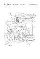
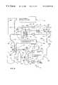
- FIG. 1is a block diagram showing a patient P undergoing treatment using the preferred embodiment of airway treatment apparatus 10 .
- apparatus 10has two major subsystems, chest wall force applicator 12 a (which applies oscillating compressive force to the chest of patient P) and air pressure input mouthpiece system 12 b (which supplies air pressure to the patient's mouth in a relationship to the compressive force).
- Chest wall force applicator 12 aincludes brushless motor 14 , vest oscillation frequency potentiometer 16 , motor controller 18 , shaft 20 , wheel 22 , reciprocating arm 24 , pin 26 , diaphragm 28 , air chamber 30 , blower 32 , vest pressure potentiometer 34 , blower controller 36 , tube 38 a with constriction 38 b , hoses 40 , and inflatable vest 42 . Oscillated air pressure is delivered to inflatable vest 42 to cause inflatable vest 42 to apply an oscillating force to the patient's chest.
- Brushless motor 14is operated by motor controller 18 at a speed which is set by vest oscillation frequency potentiometer 16 .
- Shaft 20is connected to brushless motor 14 and wheel 22 .
- Reciprocating arm 24is coupled to wheel 22 by pin 26 , which is offset from the center of wheel 22 .
- Reciprocating arm 24is also coupled to diaphragm 28 , which is part of air chamber 30 .
- Blower 32is operated by blower controller 36 based upon a control setting of potentiometer 34 .
- Tube 38 a with constriction 38 bcouples blower 32 with air chamber 30 .
- Hoses 40in turn, couple air chamber 30 with inflatable vest 42 .
- the force generated on the patient's chest by chest wall force applicator 12 ahas an oscillatory air pressure component and a steady state air pressure component.
- the steady state air pressure(or “bias line pressure”) is greater than atmospheric pressure, and the oscillatory air pressure rides on the steady state air pressure.
- a whole oscillation of chest wall force applicator 12 ais effective at moving the patient's chest, because there is no point at which pressure applied to the chest by vest 42 is below atmospheric pressure. Chest movement can only be induced while chest wall applicator 12 a has an effective pressure (i.e. greater than atmospheric pressure) on the patient's chest.
- the oscillatory air pressure componentis created by brushless motor 14 .
- the speed of brushless motor 14is selected by vest oscillation potentiometer 16 and held constant by motor controller 18 .
- Shaft 20 of brushless motor 14rotates wheel 22 which, in turn, moves reciprocating arm 24 in a linear fashion and causes diaphragm 28 to oscillate the air in air chamber 30 at a frequency selected by vest oscillation potentiometer 16 .
- the pressure created by brushless motor 14follows a sinusoidal waveform pattern.
- vest pressure potentiometer 34selects the speed of blower 32 and the speed is held constant by blower controller 36 .
- the steady state air pressureis transferred to air chainber 30 through tube 38 a .
- Constriction 38 b within tube 38 aprevents backflow of pressure pulses into blower 32 which would affect the pressure pulsation in a nonlinear manner.
- constriction 38 bis a large impedance to oscillatory airflow but a low impedance to steady state airflow.
- the steady state air pressure created by blower 32is greater than atmospheric pressure so that a whole oscillatory cycle is effective at moving the patient's chest.
- blower 32has a pressure maximum of 12 cm of water, which is well within tolerance limits of anticipated users. This is a safety feature designed so that if any component failure tended to speed up blower 32 , it would not be unsafe.
- Hoses 40convey air pressure waves from air chamber 30 to inflatable vest 42 .
- Inflatable vest 42thus, is cyclically inflated and deflated to apply HFCWO to the patient's chest at a frequency set by vest oscillation frequency potentiometer 16 about a steady state or bias line pressure set by vest pressure potentiometer 34 .
- the steady state air pressuredetermines the intensity of the chest compressions since the oscillatory air pressure rides on the steady state air pressure. Therefore, the change of pressure (delta pressure) increases with increasing steady state pressure and results in the oscillatory air pressure never being less than atmospheric pressure.
- BFCWOto the patient's chest, the patient's airways are cleared of mucus.
- Chest wall force applicator 12 aalso includes components to link it to air pressure input mouthpiece system 12 b .
- Theseinclude vest sampling tube 50 , vest pressure transducer (VPT) 52 , phase shift network 54 , line 56 , line 58 , and Oscillatory Positive Expiratory Pressure (OPEP) oscillation intensity potentiometer 60 .
- VPTvest pressure transducer
- OPEPOscillatory Positive Expiratory Pressure
- Vest sampling tube 50is connected to inflatable vest 42 at one end and vest pressure transducer 52 at the other end.
- Vest pressure transducer 52is connected to phase shift network 54 via line 56 .
- Line 58then connects phase shift network 54 to OPEP potentiometer 60 .
- vest sampling tube 50conveys vest pressure to vest pressure transducer 52 which converts it to an electrical signal representative of sensed vest pressure.
- the electrical output signal of vest pressure transducer 52is sent to phase shift network 54 via line 56 .
- Phase shift network 54compensates for delays in oscillatory pressure from chest wall force applicator 12 a being transmitted as an oscillation within the patient's lungs and to the patient's mouth.
- the signal from phase shift network 54(having a waveform representative of vest pressure applied by chest wall force applicator 12 a ) is supplied by line 58 to OPEP potentiometer 60 and then to air pressure input mouthpiece system 12 b.
- Air pressure input mouthpiece system 12 bincludes motor drive amplifier 72 , line 74 , summing junction 76 , line 78 , diaphragm 80 , linear motor 82 , air chamber 84 , sampling tube 86 , pressure transducer (PT) 88 , line 90 , low pass filter (LPF) 92 , comparator error amplifier 94 , line 96 , line 98 , Positive Expiratory Pressure (PEP) level potentiometer 100 , line 102 , blower controller motor driver 104 , blower 106 , tube 108 a with constriction 108 b , tube 110 , and mouthpiece 112 (with mouth port 112 a , air supply port 112 b , and outlet port 114 ).
- PEPPositive Expiratory Pressure
- Wiper 60 a of OPEP potentiometer 60is connected to motor drive amplifier 72 via line 74 , summing junction 76 , and line 78 .
- Motor drive amplifier 72is connected to diaphragm 80 of linear motor 82 .
- Diaphragm 80is then connected with air chamber 84 which is coupled to sampling tube 86 followed by pressure transducer 88 .
- Line 90connects pressure transducer 88 to low pass filter 92 which is followed by a connection to summing junction 76 and to comparator error amplifier 94 via lines 96 and 98 .
- Comparator error amplifier 94is also connected to PEP level potentiometer 100 through line 102 and to blower controller motor driver 104 .
- Blower controller motor driver 104provides a drive signal to blower 106 , which is coupled to air chamber 84 by tube 108 a that contains constriction 108 b .
- Tube 110extends from air chamber 84 and connects to air supply port 112 b of mouthpiece 112 .
- Mouth port 112 a of mouthpiece 112is placed in communication with the patient's mouth (i.e. either in or over the mouth). Mouthpiece 112 may also cover the patient's nose.
- Outlet port 114is located a short distance from mouthpiece 112 on tube 110 .
- OPEP potentiometer 60adjusts an Oscillatory Positive Expiratory Pressure (OPEP) intensity level to control the amount of airflow enhancement at the patient's mouth that is input to motor drive amplifier 72 .
- motor drive amplifier 72Based upon a control signal from summing junction 76 , motor drive amplifier 72 operates linear motor 82 causing diaphragm 80 of linear motor 82 to oscillate air within air chamber 84 .
- the control signalis based upon the PEP feedback signal from low pass filter 92 (which represents the steady state pressure in chamber 84 ) and the signal waveform from phase shift network 54 through OPEP potentiometer 60 .
- the oscillatory waveform created in air chamber 84is selected with the desired phase, intensity, and wave shape to perform the needed task.
- Linear motor 82is not restricted to a sinusoidal waveform and can move in any complex pattern. Other embodiments of the invention may use other components to produce the same waveforms as linear motor 82 such as a solenoid or a motor driven cam mechanism.
- Air pressure from air chamber 84is measured by sampling tube 86 and pressure transducer 88 relative to atmospheric pressure.
- the electrical signal generated by pressure transducer 88is filtered by low pass filter 92 , which has such a low frequency cutoff that the output from low pass filter 92 is essentially the average pressure in air chamber 84 produced by filtering out the effects of linear motor 82 and then carried on line 96 .
- This PEP feedback signalis carried to the minus ( ⁇ ) input of comparator error amplifier 94 by line 98 .
- PEP level potentiometer 100selects a Positive Expiratory Pressure (PEP) level which is fed into the plus (+) input of comparator error amplifier 94 via line 102 .
- PEPPositive Expiratory Pressure
- the PEP levelis adjusted by PEP level potentiometer 100 to match the mean pressure exerted on the patient's chest wall by chest wall force applicator 12 a .
- the output of comparator error amplifier 94activates blower controller motor driver 104 which maintains the speed of blower 106 . Since blower 106 communicates with air chamber 84 through tube 108 a , the steady state pressure bias is regulated within air chamber 84 . Constriction 108 b , within tube 108 a , prevents back flow of pressure pulses to blower 106 which would effect the pressure pulsation as previously discussed.
- the steady state pressure biasis maintained in the patient's mouth through communication with air chamber 84 via tube 110 and mouthpiece 112 .
- Air pressure input mouthpiece system 12 baccomplishes, in effect, a shift in the effective atmospheric pressure.
- An oscillatory airflowis produced that rides on a steady state pressure (which is greater than atmospheric pressure) in the mouth.
- the combined oscillatory pressure and steady state pressurehas a waveform, intensity, and phase relationship to the chest compressions that enhances airflow through the air passages.
- the patientperceives no vest pressure, because the steady state pressure in the mouth and lungs is equal to and opposite the pressure from chest wall force applicator 12 a , and thus, the forces counteract each other. This is very beneficial with some disease states where the external pressure on the chest from a chest wall force applicator 12 a can cause considerable distress to the patient.
- a patientmay already have difficulty breathing and would have even greater difficultly if the patient had to breathe against a force trying to compress the patient's lungs.
- Air pressure input mouthpiece system 12 balso provides an effective means of enhancing oscillations caused by chest wall force applicator 12 a without increasing the force applied on the patient's chest. Increased force on the patient's chest would be too uncomfortable. Therefore, air pressure input mouthpiece system 12 b enhances the function of chest wall force applicator 12 a by oscillating the pressure at the patient's mouth in synchronism with the airflow produced by the oscillations on the chest by chest wall force applicator 12 a.
- OPEP potentiometer 60regulates the extent to which air pressure input mouthpiece system 12 b enhances airflow velocity created by chest wall force applicator 12 a , it can alternatively be set to (a) increase the volume of the lungs slightly by increasing the pressure in air chamber 84 or (b) deflate the lungs by decreasing the pressure in air chamber 84 . This is a beneficial function, because in some disease states the lungs need to be given greater volume. In other disease states where the lungs may be hyperinflated, it is desirable to reduce the lungs' volume.
- Outlet port 114is located a short distance from mouthpiece 112 .
- the distanceis determined by the distance 100% humidified air from mouthpiece 112 travels in one cycle. This allows the humid air from the outflow half cycles to be returned to the patient's airways during the inflow half cycles, thus preventing the airways from drying out.
- the positive pressure produced by blower 106maintains a net average of airflow from blower 106 through air chamber 84 and tube 110 and out outlet port 114 . Therefore, any fluids and mucus are drained out through outlet port 114 and not passed into air chamber 84 where they could cause damage.
- this airflow streamprovides a continuous supply of fresh air for normal respiration as the much larger tidal breathing volume oscillations move fresh air from the position of outlet port 114 in tube 110 into the patient's lungs.
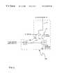
- FIG. 2shows a second embodiment of apparatus 10 , having a simulated cough inducer 12 c , which includes cough waveform generator module 160 and light interrupter 164 .
- the embodiment shown in FIG. 2is generally similar to the embodiment of FIG. 1, and similar reference characters are used to designate similar elements.
- FIG. 3shows a schematic block diagram of cough waveform generator module 160 , which includes optical sensor processor 166 , cough waveform generator 168 , line 170 , cough intensity potentiometer 172 , line 174 , and summing junction 176 .
- Light interrupter 164(FIG. 2) is attached to wheel 22 and sends signals to optical sensor processor 166 . These components make up a diaphragm position sensor which is connected to cough waveform generator 168 via line 170 . The output of cough waveform generator 168 is connected to Cough Intensity potentiometer 172 . Line 174 connects Cough Intensity potentiometer 172 with one input of summing junction 176 . Another input of summing junction 176 is connected to wiper 60 a of OPEP potentiometer 60 . Line 74 connects the output of summing junction 176 with an input of summing junction 76 . The output of summing junction 76 is connected to motor drive amplifier 72 through line 78 .
- the diaphragm position sensor formed by light interrupter 164 and optical sensor processor 166produces a timing signal that triggers the start and finish of cough waveform generator 168 .
- optical sensor processor 166activates cough waveform generator 168 .
- Optical sensor processor 166stops cough waveform generator 168 when oscillatory lung pressure reaches zero (as indicated by the position of light interrupter 164 ).
- Cough Intensity potentiometer 172determines the magnitude of the signal from cough waveform generator 168 , and the signal is carried to summing junction 176 via line 174 .
- OPEP potentiometer 60sets the level of the OPEP waveform, and this signal is also supplied to summing junction 176 .
- Summing junction 176then combines the OPEP waveform signal with the cough waveform signal from cough waveform generator 168 .
- the output of summing junction 176which includes the cough waveform set at the desired intensity, is carried through line 74 to summing junction 76 .
- the combined OPEP/cough signalis summed with the steady state pressure signal from low. pass filter 92 and is sent to motor drive amplifier 72 along line 78 .
- the pressure wave from air chamber 84causes near zero airflow out of mouthpiece 112 .
- pressure from chest wall force applicator 12 a on the chestis increasing. What results is a build up of airway pressure in the lungs with very little outward flow.
- the flow rate while inspiringis lower than the flow rate while expiring, but the volume of air during each half cycle is equal. Since this is the pattern of a natural cough, a cough is simulated with each oscillatory cycle, which can be up to 20 times/second.
- simulated cough inducer 12 ccan be utilized instead of enhancing the increased airflow velocities created by chest wall force applicator 12 a using sinusoidal enhancement with air pressure input mouthpiece system 12 b .
- OPEP potentiometer 60which adjusts the magnitude of sinusoidal enhancement
- Cough Intensity potentiometer 172which controls the magnitude of the cough waveform
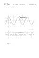
- FIGS. 4 a and 4 billustrate the cough sequence.
- FIGS. 4 a and 4 bshow pressure from chest wall force applicator 12 a on the patient's chest and airflow from the patient's mouth during a cough sequence.
- FIG. 4 ashows one oscillatory cycle and
- FIG. 4 bshows multiple oscillatory cycles.
- the sinusoidal waveis a vest pressure waveform 180 and the jagged waveform 182 is airflow at the patient's mouth.
- the high frequency oscillations of the airflow waveformare caused by resonance of the tubes within the present invention and the patient's air passages and are of no consequence.
- Line 184indicates zero airflow.
- the patientis inspiring and when below the line, the patient is expiring.
- Vest pressureincreases downward from line 186 .
- airflowis about zero. This is the period of building pressure in the lungs and is equivalent to the glottis closing during a natural cough in order to allow pressure to build in the lungs.
- vest pressurepeaks, and airflow from the mouth is at a maximum. This coincides with the rapid increase in airflow out of the mouth when the glottis opens during a natural cough. Expiratory rate is up to 3 liters/second.
- Point 190shows a gradual inspiration, as in a natural cough. Integration of the airflow waveform 182 below and above line 184 produces a net flow of zero.
- FIG. 4 bshows the cough sequence at a different time scale illustrating multiple induced coughs.
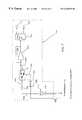
- FIG. 5shows a third embodiment of apparatus 10 which further includes airway resistance indicator 12 d .
- the embodiment shown in FIG. 5is generally similar to the embodiment shown in FIG. 1, and similar reference characters are used to designate similar elements.
- Airway resistance indicator 12 dincludes airway resistance module 200 (shown in FIG. 6 ), airway resistance null detector/indicator module 210 (shown in FIG. 7) and test switch 220 (having terminals 220 a - 220 c ).
- Airway resistance module 200(FIG. 6) includes vest pressure transducer 52 , phase shift network 54 , lines 56 and 58 , and PFT potentiometer 230 , and lines 232 and 234 .
- Vest pressure transducer 52is linked to inflatable vest 42 by vest sampling tube 50 .
- Phase shift network 54is coupled to vest pressure transducer 52 via line 56 .
- Line 58connects phase shift network 54 with PFT potentiometer 230 , which is connected to terminal 220 a of test switch 220 by line 232 .
- Line 234couples the output of vest pressure transducer 52 with airway resistance null detector/indicator 210 .
- Airway resistance null detector/indicator module 210includes pressure tube 240 , pressure transducer 242 , line 244 , capacitor 246 , double pole switch 248 , line 250 , phase shift network 252 , line 254 , integrator 256 with integrator capacitor 258 , level indicator 260 , and LEDs 262 and 264 .
- Pressure tube 240is coupled to mouthpiece 112 and pressure transducer 242 .
- the output of pressure transducer 242is connected to capacitor 246 which is connected to double pole switch 248 via line 250 .
- Double pole switch 248has one output terminal connected to integrator 256 with integrator capacitor 258 , and the other output terminal connected to ground.
- level indicator 260The input of level indicator 260 is connected to integrator 256 , and the output of level indicator 260 is connected with and selectively drives LEDs 262 and 264 . Signals from airway resistance module 200 are carried to phase shift network 252 which is connected to the control input of double pole switch 248 via line 254 .
- vest sampling tube 50conveys vest pressure to vest pressure transducer 52 (FIG. 6) which converts it to an electrical signal.
- the electrical output signal of vest pressure transducer 52is sent to phase shift network 54 via line 56 .
- Phase shift network 54compensates for delays in oscillatory pressure from chest wall force applicator 12 a being transmitted as an oscillation within the patient's lungs and to the patient's mouth.
- the signal from phase shift network 54(having a waveform representative of vest pressure applied by chest wall force applicator 12 a ) is subsequently carried by line 58 to PFT potentiometer 230 (as well as to OPEP potentiometer 60 ).
- pressure tube 240samples the pressure in the patient's mouth.
- Transducer 242(FIG. 7) converts this pressure to an electrical signal.
- the output of transducer 242is carried to capacitor 246 via line 244 .
- Line 250then carries the signal from capacitor 250 to the input of double pole switch 248 .
- Capacitor 246removes the dc signal component from the electrical output signal of pressure transducer 242 .
- a vest pressure signalis a control input into double pole switch 248 .
- Line 234inputs the vest pressure signal from vest pressure transducer 52 (FIG. 6) to phase shift network 252 , which controls the switch timing of double pole switch 248 .
- the signal from phase shift network 252is carried to double pole switch 248 through line 254 and switches to ground to discharge any accumulated charge on capacitor 246 , which prevents a dc voltage build up.
- double pole switch 248connects capacitor 246 to the input of integrator 256 to sample the mouth pressure waveform fed through capacitor 246 . If the average signal output of integrator 256 indicates that the oscillatory pressure in mouthpiece 112 is less than the lung oscillatory pressure, level indicator 260 lights LED 262 . If the average signal output of integrator 256 indicates that the oscillatory pressure in mouthpiece 112 is greater than the lung oscillatory pressure, level indicator 260 lights LED 264 .
- airway resistancemay be checked to determine the progress of lung clearance.
- test switch 220is pressed so that it connects terminal 220 a to terminal 220 c (see FIG. 5 ).
- PFT potentiometer 230 of airway resistance module 200provides an input to motor drive amplifier 72 (through test switch 220 and summing junction 76 ) and controls air pressure input mouthpiece system 12 b .
- PFT potentiometer 230is adjusted until both LED's 262 and 264 are not lit. This is the null point of pressure within the mouth-the oscillatory air pressure waves induced by chest wall force applicator 12 a are equal and opposite to the oscillatory pressure waves provided at mouthpiece 112 by air pressure input mouthpiece system 12 b .
- the airflow and air pressure in mouthpiece 112are at a magnitude equal to that flow caused by the oscillation pressure of chest wall force applicator 12 a on the patient's chest, which is transferred to the patient's lungs and is then suppressed by the resistance of the mucus in the airways as the air flows through them on the way to the patient's mouth.
- the indicator knob position of PFT potentiometer 230provides a numerical reading of the airway resistance of the patient's lungs. Using this test, progress can be checked during treatment and from one treatment to the next. All factors except airway resistance should be constant.
- a computer algorithmis used to find the null point of pressure and convert that to a numerical value for display or print out.
- a common method for determining airway resistancemeasures air flow through a restriction over time.
- the problems with this methodwhich are solved with the present invention, are that mucus can clog the restriction, the equipment needs to be calibrated, and it is maneuver-dependent on the patient. These factors can lead to erroneous results.
- FIGS. 8 a , 8 b , and 8 cgraph pressure waves from chest wall force applicator 12 a (vest pressure 300 ) and the patient's mouth through mouthpiece 112 (mouth pressure 310 ) versus time.
- FIG. 8 ais an illustration of the force from chest wall force applicator 12 a at a greater pressure than the pressure at the patient's mouth created by air pressure input mouthpiece system 12 b . This is the situation where LED 262 of airway resistance module 210 would light.
- the upper waveform 300is the oscillatory pressure of chest wall force applicator 12 a .
- the lower waveform 310is the oscillatory pressure at the patient's mouth which is the sum of the oscillations from the lungs plus oscillations from the air chamber 84 traveling down tube 110 .
- FIG. 8 bis an illustration of waveforms during the null point of pressure. Neither LED ( 262 , 264 ) would light during this period.
- the upper waveform 300is the oscillatory pressure from chest wall force applicator 12 a
- the lower waveform 310is the pressure at the patient's mouth through mouthpiece 112 .
- PFT potentiometer 230while defining the flow rate from the patient's mouth, is an analog of the airway resistance at the null point of pressure.
- the small pressure variations seen in the lower waveform 310are due to imperfections in the phase angle and shape of the two pressure waves producing less than perfect cancellation. Thus, null is indicated by a minimum in the amplitude of this waveform 310 .
- FIG. 8 cis an illustration of waveforms 300 and 310 when the pressure in mouthpiece 112 measured from tube 110 is greater than the oscillatory pressure produced by chest wall force applicator 12 a .
- LED 264lights in this situation.
- the wave shape of waveform 310is the result of the combining of two pressure waves having unequal magnitude and phase.
- the oscillations on the patient's chestbecome out of phase by 180° compared to airflow oscillations at the patient's mouth.
- FIGS. 8 a - 8 cshow that there is a null point of pressure where the two pressures cancel each other, and on either side of this point non-zero waveforms are generated.
- null point of pressureis chosen, so no calibration sequence is required of system components.
- Another advantageis that it does not require any breathing maneuvers on the part of the patient. Repeatable adherence to a maneuver is necessary for standard pulmonary function testing, therefore, tests relying on breathing maneuvers may be inaccurate, or the data may not be usable.
- FIG. 9shows a fourth embodiment of apparatus 10 which includes all of the features of the first, second and third embodiments.
- each of the systemswork together to efficiently remove mucus from the patient's lungs and provide a means of determining the progress of the treatment. At the same time, patient comfort is maintained during treatment.
- Airway treatment apparatus 10performs in such a way that the patient receiving treatment perceives no external pressure on the chest which may cause discomfort depending on the disease state of the patient. Increased oscillatory airflow velocities can be achieved over prior art vest systems, which is the key to successful lung clearance. By incorporating a mechanism to simulate a cough, outcome measuring airway treatment apparatus 10 provides better lung clearance over other vest systems and induces individuals that are not able to voluntarily cough to simulate coughs.
- control systems shown in the figuresuse analog circuitry, other embodiments use digital logic and programmable devices (such as programmable logic arrays, microcontrollers, or microprocessors) to provide the control functions.
Landscapes
- Health & Medical Sciences (AREA)
- Veterinary Medicine (AREA)
- Animal Behavior & Ethology (AREA)
- General Health & Medical Sciences (AREA)
- Public Health (AREA)
- Life Sciences & Earth Sciences (AREA)
- Heart & Thoracic Surgery (AREA)
- Hematology (AREA)
- Biomedical Technology (AREA)
- Pulmonology (AREA)
- Anesthesiology (AREA)
- Engineering & Computer Science (AREA)
- Emergency Medicine (AREA)
- Epidemiology (AREA)
- Pain & Pain Management (AREA)
- Physical Education & Sports Medicine (AREA)
- Rehabilitation Therapy (AREA)
- Percussion Or Vibration Massage (AREA)
- Measurement Of The Respiration, Hearing Ability, Form, And Blood Characteristics Of Living Organisms (AREA)
Abstract
Description
Claims (19)
Priority Applications (8)
| Application Number | Priority Date | Filing Date | Title |
|---|---|---|---|
| US09/412,768US6340025B1 (en) | 1999-10-04 | 1999-10-04 | Airway treatment apparatus with airflow enhancement |
| US09/412,459US6910479B1 (en) | 1999-10-04 | 1999-10-04 | Airway treatment apparatus with bias line cancellation |
| US09/412,086US6210345B1 (en) | 1999-10-04 | 1999-10-04 | Outcome measuring airway resistance diagnostic system |
| US09/412,457US6415791B1 (en) | 1999-10-04 | 1999-10-04 | Airway treatment apparatus with cough inducement |
| JP2001527700AJP2004500905A (en) | 1999-10-04 | 2000-08-29 | Airflow treatment device |
| AU70859/00AAU7085900A (en) | 1999-10-04 | 2000-08-29 | Airway treatment apparatus |
| EP00959562AEP1225834A4 (en) | 1999-10-04 | 2000-08-29 | Airway treatment apparatus |
| PCT/US2000/023705WO2001024698A1 (en) | 1999-10-04 | 2000-08-29 | Airway treatment apparatus |
Applications Claiming Priority (4)
| Application Number | Priority Date | Filing Date | Title |
|---|---|---|---|
| US09/412,768US6340025B1 (en) | 1999-10-04 | 1999-10-04 | Airway treatment apparatus with airflow enhancement |
| US09/412,459US6910479B1 (en) | 1999-10-04 | 1999-10-04 | Airway treatment apparatus with bias line cancellation |
| US09/412,086US6210345B1 (en) | 1999-10-04 | 1999-10-04 | Outcome measuring airway resistance diagnostic system |
| US09/412,457US6415791B1 (en) | 1999-10-04 | 1999-10-04 | Airway treatment apparatus with cough inducement |
Publications (1)
| Publication Number | Publication Date |
|---|---|
| US6340025B1true US6340025B1 (en) | 2002-01-22 |
Family
ID=27503604
Family Applications (4)
| Application Number | Title | Priority Date | Filing Date |
|---|---|---|---|
| US09/412,768Expired - LifetimeUS6340025B1 (en) | 1999-10-04 | 1999-10-04 | Airway treatment apparatus with airflow enhancement |
| US09/412,457Expired - LifetimeUS6415791B1 (en) | 1999-10-04 | 1999-10-04 | Airway treatment apparatus with cough inducement |
| US09/412,459Expired - LifetimeUS6910479B1 (en) | 1999-10-04 | 1999-10-04 | Airway treatment apparatus with bias line cancellation |
| US09/412,086Expired - LifetimeUS6210345B1 (en) | 1999-10-04 | 1999-10-04 | Outcome measuring airway resistance diagnostic system |
Family Applications After (3)
| Application Number | Title | Priority Date | Filing Date |
|---|---|---|---|
| US09/412,457Expired - LifetimeUS6415791B1 (en) | 1999-10-04 | 1999-10-04 | Airway treatment apparatus with cough inducement |
| US09/412,459Expired - LifetimeUS6910479B1 (en) | 1999-10-04 | 1999-10-04 | Airway treatment apparatus with bias line cancellation |
| US09/412,086Expired - LifetimeUS6210345B1 (en) | 1999-10-04 | 1999-10-04 | Outcome measuring airway resistance diagnostic system |
Country Status (5)
| Country | Link |
|---|---|
| US (4) | US6340025B1 (en) |
| EP (1) | EP1225834A4 (en) |
| JP (1) | JP2004500905A (en) |
| AU (1) | AU7085900A (en) |
| WO (1) | WO2001024698A1 (en) |
Cited By (55)
| Publication number | Priority date | Publication date | Assignee | Title |
|---|---|---|---|---|
| US20020082531A1 (en)* | 1999-08-31 | 2002-06-27 | Vanbrunt Nicholas P. | Pneumatic chest compression vest with front panel air bladder |
| US6539938B2 (en)* | 2000-12-15 | 2003-04-01 | Dhd Healthcare Corporation | Maximum expiratory pressure device |
| US20030126683A1 (en)* | 1998-06-26 | 2003-07-10 | Hill-Rom Services, Inc. | Hospital bed |
| US6666209B2 (en)* | 2001-02-20 | 2003-12-23 | 3M Innovative Properties Company | Method and system of calibrating air flow in a respirator system |
| US20040064076A1 (en)* | 2002-09-27 | 2004-04-01 | Jagadish Bilgi | External chest therapy blanket for infants |
| US20040097843A1 (en)* | 2002-11-15 | 2004-05-20 | Advanced Respiratory, Inc. | Oscillatory chest wall compression device with improved air pulse generator with improved air pulse module |
| US20040158177A1 (en)* | 1999-08-31 | 2004-08-12 | Van Brunt Nicholas P. | Pneumatic chest compression vest with front panel bib |
| US20040168253A1 (en)* | 1999-04-21 | 2004-09-02 | Hill-Rom Services, Inc. | Proning bed |
| US6817363B2 (en) | 2000-07-14 | 2004-11-16 | Hill-Rom Services, Inc. | Pulmonary therapy apparatus |
| US20040226091A1 (en)* | 1997-08-08 | 2004-11-18 | Hill-Rom Services, Inc. | Hospital bed |
| US20050054956A1 (en)* | 2003-09-08 | 2005-03-10 | Gagne Donald J. | Single patient use vest |
| US6910479B1 (en)* | 1999-10-04 | 2005-06-28 | Advanced Respiratory, Inc. | Airway treatment apparatus with bias line cancellation |
| US20050183722A1 (en)* | 2002-09-27 | 2005-08-25 | Jagadish Bilgi | External chest therapy blanket for infants |
| US20060011195A1 (en)* | 2004-07-14 | 2006-01-19 | Ric Investments, Llc. | Method and apparatus for non-rebreathing positive airway pressure ventilation |
| US20060036199A1 (en)* | 1999-07-02 | 2006-02-16 | Warwick Warren J | Chest compression apparatus |
| US20070093731A1 (en)* | 1999-07-02 | 2007-04-26 | Warwick Warren J | Chest compression apparatus |
| US20080000477A1 (en)* | 2006-03-15 | 2008-01-03 | Huster Keith A | High frequency chest wall oscillation system |
| US20080021355A1 (en)* | 2006-05-10 | 2008-01-24 | Hill-Rom Services, Inc. | Data handling for high frequency chest wall oscillation system |
| US20080066754A1 (en)* | 2006-09-15 | 2008-03-20 | Faram Joseph D | Continuous high-frequency oscillation breathing treatment apparatus |
| US20080245368A1 (en)* | 2007-04-02 | 2008-10-09 | Dunsmore Thomas J | High frequency oscillation respiratory therapy |
| US20080283051A1 (en)* | 2007-05-18 | 2008-11-20 | Joseph Dee Faram | Lung therapy device |
| US20080294075A1 (en)* | 2007-04-19 | 2008-11-27 | Mario Nozzarella | Air Vest for Chest Compression Apparatus |
| US20090013470A1 (en)* | 2007-05-31 | 2009-01-15 | Richards Sandy M | Pulmonary mattress |
| US20090126731A1 (en)* | 2007-11-19 | 2009-05-21 | Allegiance Corporation | Patient interface assembly for respiratory therapy |
| US20090221941A1 (en)* | 2006-12-13 | 2009-09-03 | Ikeler Timothy J | Efficient high frequency chest wall oscilliation system |
| US20090264256A1 (en)* | 2008-04-22 | 2009-10-22 | Boerst Chad M | Breathing exercise apparatus |
| US7779841B2 (en) | 2006-11-13 | 2010-08-24 | Carefusion 2200, Inc. | Respiratory therapy device and method |
| US7785280B2 (en) | 2005-10-14 | 2010-08-31 | Hill-Rom Services, Inc. | Variable stroke air pulse generator |
| US7909033B2 (en) | 2006-05-03 | 2011-03-22 | Comedica Incorporated | Breathing treatment apparatus |
| US20110087143A1 (en)* | 2009-10-14 | 2011-04-14 | Bobey John A | Three-dimensional layer for a garment of a hfcwo system |
| US20110100360A1 (en)* | 2009-11-02 | 2011-05-05 | Joseph Dee Faram | Composite lung therapy device and method |
| US20110100364A1 (en)* | 2009-11-02 | 2011-05-05 | Joseph Dee Faram | Multiple conduit connector apparatus and method |
| US8257288B2 (en) | 2000-06-29 | 2012-09-04 | Respirtech | Chest compression apparatus having physiological sensor accessory |
| US8485179B1 (en) | 2009-02-23 | 2013-07-16 | Trudell Medical International | Oscillating positive expiratory pressure device |
| US8539951B1 (en) | 2008-05-27 | 2013-09-24 | Trudell Medical International | Oscillating positive respiratory pressure device |
| US20140150791A1 (en)* | 2012-12-03 | 2014-06-05 | Hill-Rom Services Pte. Ltd. | Combination respiratory therapy device, system, and method |
| US8985111B2 (en) | 2008-10-28 | 2015-03-24 | Trudell Medical International | Oscillating positive expiratory pressure device |
| USD731050S1 (en) | 2011-06-06 | 2015-06-02 | Trudell Medical International | Oscillating positive expiratory pressure device |
| US9149589B2 (en) | 2009-02-23 | 2015-10-06 | Trudell Medical International | Method and device for performing orientation dependent oscillating positive expiratory pressure therapy |
| US9180271B2 (en) | 2012-03-05 | 2015-11-10 | Hill-Rom Services Pte. Ltd. | Respiratory therapy device having standard and oscillatory PEP with nebulizer |
| US9517315B2 (en) | 2012-11-30 | 2016-12-13 | Trudell Medical International | Oscillating positive expiratory pressure device |
| USD778429S1 (en) | 2015-09-02 | 2017-02-07 | Trudell Medical International | Respiratory treatment device |
| USD780906S1 (en) | 2015-09-02 | 2017-03-07 | Trudell Medical International | Respiratory treatment device |
| US9849257B2 (en) | 2013-08-22 | 2017-12-26 | Trudell Medical International | Oscillating positive respiratory pressure device |
| US10004872B1 (en) | 2015-03-06 | 2018-06-26 | D R Burton Healthcare, Llc | Positive expiratory pressure device having an oscillating valve |
| US10272224B2 (en) | 2013-07-12 | 2019-04-30 | Trudell Medical International | Huff cough simulation device |
| US10363383B2 (en) | 2014-02-07 | 2019-07-30 | Trudell Medical International | Pressure indicator for an oscillating positive expiratory pressure device |
| US10449324B2 (en) | 2015-07-30 | 2019-10-22 | Trudell Medical International | Combined respiratory muscle training and oscillating positive expiratory pressure device |
| US10518048B2 (en) | 2015-07-31 | 2019-12-31 | Hill-Rom Services, PTE Ltd. | Coordinated control of HFCWO and cough assist devices |
| US10857317B2 (en) | 2015-12-04 | 2020-12-08 | Trudell Medical International | Huff cough simulation device |
| US10905836B2 (en) | 2015-04-02 | 2021-02-02 | Hill-Rom Services Pte. Ltd. | Manifold for respiratory device |
| US10945699B2 (en) | 2016-12-28 | 2021-03-16 | Hill-Rom Services Pte Ltd. | Respiratory sound analysis for lung health assessment |
| US10953278B2 (en) | 2018-02-02 | 2021-03-23 | Trudell Medical International | Oscillating positive expiratory pressure device |
| US11559723B2 (en) | 2017-05-03 | 2023-01-24 | Trudell Medical International | Combined oscillating positive expiratory pressure therapy and Huff Cough simulation device |
| US12080401B2 (en) | 2012-12-03 | 2024-09-03 | Metrohealth Ventures Llc | Combination respiratory therapy device, system and method |
Families Citing this family (68)
| Publication number | Priority date | Publication date | Assignee | Title |
|---|---|---|---|---|
| US6557554B1 (en)* | 1999-10-29 | 2003-05-06 | Suzuki Motor Corporation | High-frequency oscillation artificial respiration apparatus |
| US7059324B2 (en)* | 1999-11-24 | 2006-06-13 | Smiths Medical Asd, Inc. | Positive expiratory pressure device with bypass |
| JP3721912B2 (en)* | 2000-01-11 | 2005-11-30 | スズキ株式会社 | High frequency ventilator |
| WO2003075256A1 (en)* | 2002-03-05 | 2003-09-12 | Nec Corporation | Image display and its control method |
| EP1343112A1 (en) | 2002-03-08 | 2003-09-10 | EndoArt S.A. | Implantable device |
| ITMI20021273A1 (en)* | 2002-06-11 | 2003-12-11 | Milano Politecnico | SYSTEM AND METHOD FOR THE AUTOMATIC DETECTION OF THE EXPIRATORY FLOW LIMITATION |
| US7338433B2 (en) | 2002-08-13 | 2008-03-04 | Allergan, Inc. | Remotely adjustable gastric banding method |
| DK1553878T3 (en)* | 2002-08-28 | 2010-05-31 | Allergan Inc | Fatigue resistant gastric banding device |
| US7416536B2 (en) | 2002-10-02 | 2008-08-26 | Devlieger Marten Jan | Chest vibrating device |
| CA2543725A1 (en)* | 2002-10-28 | 2004-05-06 | John Perrier | Ultrasonic medical device |
| GB0318935D0 (en)* | 2003-08-13 | 2003-09-17 | Mossanen Shams Iden | Pulmonary evaluation device |
| US20050126578A1 (en)* | 2003-12-12 | 2005-06-16 | Garrison Richard L. | External pressure garment in combination with a complementary positive pressure ventilator for pulmocardiac assistance |
| RU2240767C1 (en)* | 2003-12-29 | 2004-11-27 | Зао "Вниимп-Вита" | Apparatus for carrying out artificial lung ventilation |
| JP2007527279A (en) | 2004-01-23 | 2007-09-27 | アラーガン、インコーポレイテッド | One-piece adjustable gastric band that can be fixed removably |
| CA2559056A1 (en)* | 2004-03-08 | 2005-09-22 | Endoart S.A. | Closure system for tubular organs |
| EP1732635B1 (en)* | 2004-03-18 | 2011-07-27 | Allergan, Inc. | Apparatus for volume adjustment of intragastric balloons |
| US7195014B2 (en)* | 2005-03-22 | 2007-03-27 | Hoffman Laboratories, Llc | Portable continuous positive airway pressure system |
| US8251888B2 (en) | 2005-04-13 | 2012-08-28 | Mitchell Steven Roslin | Artificial gastric valve |
| US7798954B2 (en) | 2006-01-04 | 2010-09-21 | Allergan, Inc. | Hydraulic gastric band with collapsible reservoir |
| US8043206B2 (en) | 2006-01-04 | 2011-10-25 | Allergan, Inc. | Self-regulating gastric band with pressure data processing |
| US20070163600A1 (en)* | 2006-01-11 | 2007-07-19 | Leslie Hoffman | User interface and head gear for a continuous positive airway pressure device |
| WO2007106804A2 (en)* | 2006-03-15 | 2007-09-20 | Hill-Rom Services, Inc. | High frequency chest wall oscillation system |
| US7861716B2 (en) | 2006-03-15 | 2011-01-04 | Carefusion 207, Inc. | Closed loop control system for a high frequency oscillation ventilator |
| US9182398B2 (en)* | 2006-04-01 | 2015-11-10 | Medical Service Consultation International, Llc | Methods and compositions for detecting fungi and mycotoxins |
| US7594508B2 (en)* | 2006-07-13 | 2009-09-29 | Ric Investments, Llc. | Ventilation system employing synchronized delivery of positive and negative pressure ventilation |
| US20080300515A1 (en)* | 2006-12-28 | 2008-12-04 | Mario Nozzarella | Focused Chest Compression System and Method of Using Same |
| US8714153B2 (en)* | 2007-04-16 | 2014-05-06 | Ric Investments, Llc | Method for selecting a device adapted to treat disordered breathing |
| GB0712710D0 (en)* | 2007-06-29 | 2007-08-08 | Laerdal Medical As | Method and instrument to provide ventilation and perfusion |
| US20100075322A1 (en)* | 2008-08-22 | 2010-03-25 | Hooper Dennis G | Methods and Compositions for Identifying Mycotoxins and Fungal Species |
| US20100068718A1 (en)* | 2008-08-22 | 2010-03-18 | Hooper Dennis G | Methods and Compositions for Identifying Yeast |
| WO2010042493A1 (en) | 2008-10-06 | 2010-04-15 | Allergan, Inc. | Mechanical gastric band with cushions |
| US20100185049A1 (en) | 2008-10-22 | 2010-07-22 | Allergan, Inc. | Dome and screw valves for remotely adjustable gastric banding systems |
| JP5785543B2 (en) | 2009-07-24 | 2015-09-30 | コーニンクレッカ フィリップス エヌ ヴェ | Device and method for assisting cough |
| US20110137112A1 (en)* | 2009-08-28 | 2011-06-09 | Allergan, Inc. | Gastric band with electric stimulation |
| WO2011031400A2 (en)* | 2009-08-28 | 2011-03-17 | Allergan, Inc. | Gastric band with electric stimulation |
| US8962251B2 (en) | 2009-10-08 | 2015-02-24 | Medical Service Consultation International, Llc | Methods and compositions for identifying sulfur and iron modifying bacteria |
| WO2011058470A1 (en)* | 2009-11-13 | 2011-05-19 | Koninklijke Philips Electronics N.V. | Method and device for airway clearance |
| US8758221B2 (en)* | 2010-02-24 | 2014-06-24 | Apollo Endosurgery, Inc. | Source reservoir with potential energy for remotely adjustable gastric banding system |
| US8840541B2 (en) | 2010-02-25 | 2014-09-23 | Apollo Endosurgery, Inc. | Pressure sensing gastric banding system |
| US20110270024A1 (en) | 2010-04-29 | 2011-11-03 | Allergan, Inc. | Self-adjusting gastric band having various compliant components |
| US9028394B2 (en) | 2010-04-29 | 2015-05-12 | Apollo Endosurgery, Inc. | Self-adjusting mechanical gastric band |
| US9044298B2 (en) | 2010-04-29 | 2015-06-02 | Apollo Endosurgery, Inc. | Self-adjusting gastric band |
| US20110270025A1 (en) | 2010-04-30 | 2011-11-03 | Allergan, Inc. | Remotely powered remotely adjustable gastric band system |
| US8517915B2 (en) | 2010-06-10 | 2013-08-27 | Allergan, Inc. | Remotely adjustable gastric banding system |
| US20120059216A1 (en) | 2010-09-07 | 2012-03-08 | Allergan, Inc. | Remotely adjustable gastric banding system |
| US8961393B2 (en) | 2010-11-15 | 2015-02-24 | Apollo Endosurgery, Inc. | Gastric band devices and drive systems |
| US8676529B2 (en) | 2011-01-31 | 2014-03-18 | Covidien Lp | Systems and methods for simulation and software testing |
| US8788236B2 (en) | 2011-01-31 | 2014-07-22 | Covidien Lp | Systems and methods for medical device testing |
| WO2013042007A1 (en)* | 2011-09-21 | 2013-03-28 | Koninklijke Philips Electronics N.V. | Upper airway resistance measurement device |
| US8876694B2 (en) | 2011-12-07 | 2014-11-04 | Apollo Endosurgery, Inc. | Tube connector with a guiding tip |
| US8961394B2 (en) | 2011-12-20 | 2015-02-24 | Apollo Endosurgery, Inc. | Self-sealing fluid joint for use with a gastric band |
| US10092717B2 (en)* | 2012-02-08 | 2018-10-09 | Koninklijke Philips N.V. | Method and apparatus for increasing cough flow |
| EP2934316B1 (en)* | 2012-12-19 | 2022-09-07 | Koninklijke Philips N.V. | Detection of respiratory disorders |
| US8956821B2 (en) | 2013-02-06 | 2015-02-17 | Medical Service Consultation International, Llc | Methods and compositions for detecting Aspergillus terreus, Aspergillus niger, and mycotoxins |
| US9833584B2 (en) | 2013-03-22 | 2017-12-05 | Breathe Technologies, Inc. | Portable ventilator secretion management system |
| GB201401566D0 (en)* | 2014-01-30 | 2014-03-19 | Smiths Medical Int Ltd | Respiratory therapy systems, sensors and methods |
| CN103989575A (en)* | 2014-06-09 | 2014-08-20 | 河北爱西欧医疗设备科技有限公司 | Multi-cavity cam sputum excretion system |
| JP6786198B2 (en)* | 2015-05-01 | 2020-11-18 | 株式会社フジ医療器 | Air massage device |
| US11529478B2 (en) | 2016-02-22 | 2022-12-20 | Advanced Bio Machines Pte. Ltd. | Oscillatory respiratory care apparatus |
| US11833096B2 (en)* | 2016-03-21 | 2023-12-05 | The Trustees Of The University Of Pennsylvania | Ambulatory respiratory assist device |
| US11432995B2 (en)* | 2018-08-29 | 2022-09-06 | Leggett & Platt Canada Co. | Pneumatic massage |
| CA3123027A1 (en) | 2018-12-17 | 2020-06-25 | The Trustees Of The University Of Pennsylvania | Improvements on ambulatory respiratory assist device |
| US12070554B2 (en) | 2019-11-11 | 2024-08-27 | Hill-Rom Services Pte. Ltd. | Pneumatic connector apparatus and method |
| CN115666394A (en) | 2020-04-22 | 2023-01-31 | 戴尔哈修墨医学研究内结构和服务有限公司 | Pulmonary airway clearance |
| US20220192913A1 (en)* | 2020-12-20 | 2022-06-23 | Mego Afek Ac Ltd. | System, device and method for providing compression therapy in synchronization with breathing cycle |
| NL2027207B1 (en)* | 2020-12-23 | 2022-04-05 | Demcon Macawi Respiratory Systems B V | Ventilation system for ventilating a subject |
| GB202214528D0 (en) | 2022-10-03 | 2022-11-16 | Owlstone Med Ltd | A compound |
| US11839587B1 (en) | 2023-02-03 | 2023-12-12 | RightAir, Inc. | Systems, devices, and methods for ambulatory respiration assistance |
Citations (67)
| Publication number | Priority date | Publication date | Assignee | Title |
|---|---|---|---|---|
| US402779A (en)* | 1889-05-07 | Emphysema | ||
| US2354397A (en) | 1941-12-26 | 1944-07-25 | Gen Motors Corp | Jacket type respirator |
| US2436853A (en)* | 1944-04-10 | 1948-03-02 | Edwin D Coleman | Respiration apparatus |
| US2588192A (en) | 1947-02-01 | 1952-03-04 | Akerman | Artificial respiration apparatus |
| US2626601A (en) | 1950-07-28 | 1953-01-27 | John P Riley | Vacuum pulsating exercising apparatus |
| US2762366A (en) | 1954-12-29 | 1956-09-11 | Conitech Ltd | Artificial respiration apparatus |
| US2772673A (en) | 1952-06-18 | 1956-12-04 | Conitech Ltd | Artificial respiration apparatus |
| US2779329A (en) | 1953-06-17 | 1957-01-29 | Conitech Ltd | Artificial respiration apparatus |
| US2780222A (en) | 1953-12-18 | 1957-02-05 | J J Monaghan Company Inc | Respirators |
| US2818853A (en) | 1955-11-15 | 1958-01-07 | Conitech Ltd | Pressure regulator |
| US2832335A (en) | 1953-10-02 | 1958-04-29 | Conitech Ltd | Artificial respiration apparatus |
| US2869537A (en) | 1957-06-14 | 1959-01-20 | Chu John Jen-Chu | Pneumatic pressure respiratory vest |
| US3043292A (en) | 1959-06-26 | 1962-07-10 | Emanuel S Mendelson | Inflatable, double-walled resuscitation garment |
| US3063444A (en) | 1956-02-13 | 1962-11-13 | Jobst Institute | Means for stimulating the flow of fluids in animal bodies |
| US3120228A (en) | 1960-11-07 | 1964-02-04 | Harris A Thompson | Respirator apparatus |
| US3310050A (en) | 1964-04-02 | 1967-03-21 | Goldfarb Herman | Massaging garment with vibrators located in back and chest sections |
| US3333581A (en) | 1964-03-27 | 1967-08-01 | Elbert W Robinson | Pulmonary resuscitator with electrical control system |
| US3536063A (en) | 1967-05-31 | 1970-10-27 | Werding Winfried J | Apparatus for therapeutic care of the legs |
| US3566862A (en) | 1968-08-01 | 1971-03-02 | Paul A Schuh | Respiration apparatus |
| US3683655A (en) | 1970-03-27 | 1972-08-15 | Arlton H White | Breathing assist apparatus |
| US3742939A (en) | 1971-02-24 | 1973-07-03 | W Sayer | Method and apparatus for determining respiratory airway resistance |
| US3760801A (en) | 1971-03-22 | 1973-09-25 | A Borgeas | Therapeutic exercising apparatus for torso and body extremities |
| US3802417A (en) | 1968-12-21 | 1974-04-09 | V Lang | Device for combined monitoring and stimulation of respiration |
| US3896794A (en) | 1973-12-14 | 1975-07-29 | British Oxygen Co Ltd | Venous flow stimulator |
| US3993053A (en) | 1974-08-05 | 1976-11-23 | Murray Grossan | Pulsating massage system |
| US4051843A (en) | 1975-02-26 | 1977-10-04 | Siemens Aktiengesellschaft | Apparatus for the determination of the respiratory passageway resistance |
| US4079733A (en) | 1976-06-02 | 1978-03-21 | Hamburg Group | Percussion vibrator device for treatment of patients to assist expectoration of retained secretions |
| US4133305A (en) | 1976-03-17 | 1979-01-09 | Rudolf Steuer | Relaxation apparatus including mattress and pneumatic vibrating device |
| US4311135A (en) | 1979-10-29 | 1982-01-19 | Brueckner Gerald G | Apparatus to assist leg venous and skin circulation |
| US4349015A (en)* | 1980-11-14 | 1982-09-14 | Physio-Control Corporation | Manually-actuable CPR apparatus |
| US4397306A (en) | 1981-03-23 | 1983-08-09 | The John Hopkins University | Integrated system for cardiopulmonary resuscitation and circulation support |
| US4398531A (en) | 1979-06-21 | 1983-08-16 | Hudson Oxygen Therapy Sales Company | Percussor |
| US4424806A (en) | 1981-03-12 | 1984-01-10 | Physio-Control Corporation | Automated ventilation, CPR, and circulatory assistance apparatus |
| US4429688A (en) | 1980-12-08 | 1984-02-07 | Duffy Peter B | Medical appliance for percussive respiratory therapy |
| US4546764A (en) | 1983-04-08 | 1985-10-15 | Invacare Corporation | Postural drainage bed |
| US4621621A (en) | 1985-02-19 | 1986-11-11 | Marsalis John P | Vacuum valve system |
| US4676232A (en) | 1982-11-19 | 1987-06-30 | Siemens Elema Ab | Respirator and a method of utilizing the respirator to promote blood circulation |
| US4815452A (en) | 1986-02-04 | 1989-03-28 | Zamir Hayek | Ventilator apparatus and fluid control valve |
| US4838263A (en) | 1987-05-01 | 1989-06-13 | Regents Of The University Of Minnesota | Chest compression apparatus |
| US4886057A (en) | 1987-11-30 | 1989-12-12 | E Z Breathe, Inc. | Assisted breathing interface device |
| US4928674A (en) | 1988-11-21 | 1990-05-29 | The Johns Hopkins University | Cardiopulmonary resuscitation and assisted circulation system |
| US4971042A (en)* | 1988-11-14 | 1990-11-20 | Lerman Samuel I | Cardiac assist curiass |
| US4977889A (en) | 1989-10-12 | 1990-12-18 | Regents Of The University Of Minnesota | Fitting and tuning chest compression device |
| US4982735A (en) | 1988-03-01 | 1991-01-08 | Sumitomo Bakelite Company Limited | Artificial ventilator |
| US5056505A (en) | 1987-05-01 | 1991-10-15 | Regents Of The University Of Minnesota | Chest compression apparatus |
| US5076259A (en) | 1989-01-16 | 1991-12-31 | Dranez Anstalt | Chest enclosures for ventilators |
| US5101808A (en) | 1989-08-23 | 1992-04-07 | Nihon Kohden Corporation | Outside-of-thorax type negative pressure artificial respirator |
| US5193745A (en) | 1989-03-07 | 1993-03-16 | Karl Holm | Atomizing nozzle device for atomizing a fluid and an inhaler |
| EP0542383A2 (en) | 1991-11-12 | 1993-05-19 | The Kendall Company | Compression device |
| US5222478A (en) | 1988-11-21 | 1993-06-29 | Scarberry Eugene N | Apparatus for application of pressure to a human body |
| US5261394A (en) | 1991-09-30 | 1993-11-16 | Triangle Research And Development Corporation | Percussive aid for the treatment of chronic lung disease |
| US5299599A (en) | 1992-09-17 | 1994-04-05 | Lifecare International, Inc. | Valving arrangement for a negative pressure ventilator |
| US5453081A (en) | 1993-07-12 | 1995-09-26 | Hansen; Craig N. | Pulsator |
| US5455159A (en) | 1988-04-04 | 1995-10-03 | Univ Johns Hopkins | Method for early detection of lung cancer |
| US5492115A (en)* | 1993-12-08 | 1996-02-20 | Abramov; Vladimir V. | Resuscitation breathing apparatus |
| US5569122A (en) | 1994-05-11 | 1996-10-29 | Cegla; Ulrich | Therapeutic device for improving breathing |
| US5606754A (en) | 1989-03-09 | 1997-03-04 | Ssi Medical Services, Inc. | Vibratory patient support system |
| US5720709A (en) | 1995-10-25 | 1998-02-24 | S.M.C. Sleep Medicine Center | Apparatus and method for measuring respiratory airway resistance and airway collapsibility in patients |
| US5769797A (en) | 1996-06-11 | 1998-06-23 | American Biosystems, Inc. | Oscillatory chest compression device |
| US5806512A (en)* | 1996-10-24 | 1998-09-15 | Life Support Technologies, Inc. | Cardiac/pulmonary resuscitation method and apparatus |
| US5891062A (en) | 1994-10-07 | 1999-04-06 | Datascope Investment Corp. | Active compression/decompression device and method for cardiopulmonary resuscitation |
| US5910071A (en) | 1995-02-10 | 1999-06-08 | Hougen; Everett D. | Portable, personal breathing apparatus |
| US5997488A (en)* | 1996-10-09 | 1999-12-07 | Cardiologic Systems, Inc. | Cardiopulmonary resuscitation system with centrifugal compression pump |
| US6030353A (en) | 1998-04-28 | 2000-02-29 | American Biosystems, Inc. | Pneumatic chest compression apparatus |
| US6066101A (en) | 1998-04-20 | 2000-05-23 | University Of Maryland | Airflow perturbation device and method for measuring respiratory resistance |
| US6068602A (en) | 1997-09-26 | 2000-05-30 | Ohmeda Inc. | Method and apparatus for determining airway resistance and lung compliance |
| US6210345B1 (en)* | 1999-10-04 | 2001-04-03 | American Biosystems, Inc. | Outcome measuring airway resistance diagnostic system |
Family Cites Families (3)
| Publication number | Priority date | Publication date | Assignee | Title |
|---|---|---|---|---|
| US4326507A (en) | 1979-11-20 | 1982-04-27 | Michigan Instruments, Inc. | CPR Protocol and cardiopulmonary resuscitator for effecting the same |
| SU1247009A1 (en) | 1985-01-28 | 1986-07-30 | Тульский Ордена Трудового Красного Знамени Политехнический Институт | Artificial respiration apparatus |
| US5833711A (en)* | 1996-04-01 | 1998-11-10 | Cardi-Act, L.L.C. | Method and means for portable emergency cardiopulmonary resuscitation |
- 1999
- 1999-10-04USUS09/412,768patent/US6340025B1/ennot_activeExpired - Lifetime
- 1999-10-04USUS09/412,457patent/US6415791B1/ennot_activeExpired - Lifetime
- 1999-10-04USUS09/412,459patent/US6910479B1/ennot_activeExpired - Lifetime
- 1999-10-04USUS09/412,086patent/US6210345B1/ennot_activeExpired - Lifetime
- 2000
- 2000-08-29EPEP00959562Apatent/EP1225834A4/ennot_activeWithdrawn
- 2000-08-29AUAU70859/00Apatent/AU7085900A/ennot_activeAbandoned
- 2000-08-29JPJP2001527700Apatent/JP2004500905A/ennot_activeWithdrawn
- 2000-08-29WOPCT/US2000/023705patent/WO2001024698A1/ennot_activeApplication Discontinuation
Patent Citations (67)
| Publication number | Priority date | Publication date | Assignee | Title |
|---|---|---|---|---|
| US402779A (en)* | 1889-05-07 | Emphysema | ||
| US2354397A (en) | 1941-12-26 | 1944-07-25 | Gen Motors Corp | Jacket type respirator |
| US2436853A (en)* | 1944-04-10 | 1948-03-02 | Edwin D Coleman | Respiration apparatus |
| US2588192A (en) | 1947-02-01 | 1952-03-04 | Akerman | Artificial respiration apparatus |
| US2626601A (en) | 1950-07-28 | 1953-01-27 | John P Riley | Vacuum pulsating exercising apparatus |
| US2772673A (en) | 1952-06-18 | 1956-12-04 | Conitech Ltd | Artificial respiration apparatus |
| US2779329A (en) | 1953-06-17 | 1957-01-29 | Conitech Ltd | Artificial respiration apparatus |
| US2832335A (en) | 1953-10-02 | 1958-04-29 | Conitech Ltd | Artificial respiration apparatus |
| US2780222A (en) | 1953-12-18 | 1957-02-05 | J J Monaghan Company Inc | Respirators |
| US2762366A (en) | 1954-12-29 | 1956-09-11 | Conitech Ltd | Artificial respiration apparatus |
| US2818853A (en) | 1955-11-15 | 1958-01-07 | Conitech Ltd | Pressure regulator |
| US3063444A (en) | 1956-02-13 | 1962-11-13 | Jobst Institute | Means for stimulating the flow of fluids in animal bodies |
| US2869537A (en) | 1957-06-14 | 1959-01-20 | Chu John Jen-Chu | Pneumatic pressure respiratory vest |
| US3043292A (en) | 1959-06-26 | 1962-07-10 | Emanuel S Mendelson | Inflatable, double-walled resuscitation garment |
| US3120228A (en) | 1960-11-07 | 1964-02-04 | Harris A Thompson | Respirator apparatus |
| US3333581A (en) | 1964-03-27 | 1967-08-01 | Elbert W Robinson | Pulmonary resuscitator with electrical control system |
| US3310050A (en) | 1964-04-02 | 1967-03-21 | Goldfarb Herman | Massaging garment with vibrators located in back and chest sections |
| US3536063A (en) | 1967-05-31 | 1970-10-27 | Werding Winfried J | Apparatus for therapeutic care of the legs |
| US3566862A (en) | 1968-08-01 | 1971-03-02 | Paul A Schuh | Respiration apparatus |
| US3802417A (en) | 1968-12-21 | 1974-04-09 | V Lang | Device for combined monitoring and stimulation of respiration |
| US3683655A (en) | 1970-03-27 | 1972-08-15 | Arlton H White | Breathing assist apparatus |
| US3742939A (en) | 1971-02-24 | 1973-07-03 | W Sayer | Method and apparatus for determining respiratory airway resistance |
| US3760801A (en) | 1971-03-22 | 1973-09-25 | A Borgeas | Therapeutic exercising apparatus for torso and body extremities |
| US3896794A (en) | 1973-12-14 | 1975-07-29 | British Oxygen Co Ltd | Venous flow stimulator |
| US3993053A (en) | 1974-08-05 | 1976-11-23 | Murray Grossan | Pulsating massage system |
| US4051843A (en) | 1975-02-26 | 1977-10-04 | Siemens Aktiengesellschaft | Apparatus for the determination of the respiratory passageway resistance |
| US4133305A (en) | 1976-03-17 | 1979-01-09 | Rudolf Steuer | Relaxation apparatus including mattress and pneumatic vibrating device |
| US4079733A (en) | 1976-06-02 | 1978-03-21 | Hamburg Group | Percussion vibrator device for treatment of patients to assist expectoration of retained secretions |
| US4398531A (en) | 1979-06-21 | 1983-08-16 | Hudson Oxygen Therapy Sales Company | Percussor |
| US4311135A (en) | 1979-10-29 | 1982-01-19 | Brueckner Gerald G | Apparatus to assist leg venous and skin circulation |
| US4349015A (en)* | 1980-11-14 | 1982-09-14 | Physio-Control Corporation | Manually-actuable CPR apparatus |
| US4429688A (en) | 1980-12-08 | 1984-02-07 | Duffy Peter B | Medical appliance for percussive respiratory therapy |
| US4424806A (en) | 1981-03-12 | 1984-01-10 | Physio-Control Corporation | Automated ventilation, CPR, and circulatory assistance apparatus |
| US4397306A (en) | 1981-03-23 | 1983-08-09 | The John Hopkins University | Integrated system for cardiopulmonary resuscitation and circulation support |
| US4676232A (en) | 1982-11-19 | 1987-06-30 | Siemens Elema Ab | Respirator and a method of utilizing the respirator to promote blood circulation |
| US4546764A (en) | 1983-04-08 | 1985-10-15 | Invacare Corporation | Postural drainage bed |
| US4621621A (en) | 1985-02-19 | 1986-11-11 | Marsalis John P | Vacuum valve system |
| US4815452A (en) | 1986-02-04 | 1989-03-28 | Zamir Hayek | Ventilator apparatus and fluid control valve |
| US5056505A (en) | 1987-05-01 | 1991-10-15 | Regents Of The University Of Minnesota | Chest compression apparatus |
| US4838263A (en) | 1987-05-01 | 1989-06-13 | Regents Of The University Of Minnesota | Chest compression apparatus |
| US4886057A (en) | 1987-11-30 | 1989-12-12 | E Z Breathe, Inc. | Assisted breathing interface device |
| US4982735A (en) | 1988-03-01 | 1991-01-08 | Sumitomo Bakelite Company Limited | Artificial ventilator |
| US5455159A (en) | 1988-04-04 | 1995-10-03 | Univ Johns Hopkins | Method for early detection of lung cancer |
| US4971042A (en)* | 1988-11-14 | 1990-11-20 | Lerman Samuel I | Cardiac assist curiass |
| US4928674A (en) | 1988-11-21 | 1990-05-29 | The Johns Hopkins University | Cardiopulmonary resuscitation and assisted circulation system |
| US5222478A (en) | 1988-11-21 | 1993-06-29 | Scarberry Eugene N | Apparatus for application of pressure to a human body |
| US5076259A (en) | 1989-01-16 | 1991-12-31 | Dranez Anstalt | Chest enclosures for ventilators |
| US5193745A (en) | 1989-03-07 | 1993-03-16 | Karl Holm | Atomizing nozzle device for atomizing a fluid and an inhaler |
| US5606754A (en) | 1989-03-09 | 1997-03-04 | Ssi Medical Services, Inc. | Vibratory patient support system |
| US5101808A (en) | 1989-08-23 | 1992-04-07 | Nihon Kohden Corporation | Outside-of-thorax type negative pressure artificial respirator |
| US4977889A (en) | 1989-10-12 | 1990-12-18 | Regents Of The University Of Minnesota | Fitting and tuning chest compression device |
| US5261394A (en) | 1991-09-30 | 1993-11-16 | Triangle Research And Development Corporation | Percussive aid for the treatment of chronic lung disease |
| EP0542383A2 (en) | 1991-11-12 | 1993-05-19 | The Kendall Company | Compression device |
| US5299599A (en) | 1992-09-17 | 1994-04-05 | Lifecare International, Inc. | Valving arrangement for a negative pressure ventilator |
| US5453081A (en) | 1993-07-12 | 1995-09-26 | Hansen; Craig N. | Pulsator |
| US5492115A (en)* | 1993-12-08 | 1996-02-20 | Abramov; Vladimir V. | Resuscitation breathing apparatus |
| US5569122A (en) | 1994-05-11 | 1996-10-29 | Cegla; Ulrich | Therapeutic device for improving breathing |
| US5891062A (en) | 1994-10-07 | 1999-04-06 | Datascope Investment Corp. | Active compression/decompression device and method for cardiopulmonary resuscitation |
| US5910071A (en) | 1995-02-10 | 1999-06-08 | Hougen; Everett D. | Portable, personal breathing apparatus |
| US5720709A (en) | 1995-10-25 | 1998-02-24 | S.M.C. Sleep Medicine Center | Apparatus and method for measuring respiratory airway resistance and airway collapsibility in patients |
| US5769797A (en) | 1996-06-11 | 1998-06-23 | American Biosystems, Inc. | Oscillatory chest compression device |
| US5997488A (en)* | 1996-10-09 | 1999-12-07 | Cardiologic Systems, Inc. | Cardiopulmonary resuscitation system with centrifugal compression pump |
| US5806512A (en)* | 1996-10-24 | 1998-09-15 | Life Support Technologies, Inc. | Cardiac/pulmonary resuscitation method and apparatus |
| US6068602A (en) | 1997-09-26 | 2000-05-30 | Ohmeda Inc. | Method and apparatus for determining airway resistance and lung compliance |
| US6066101A (en) | 1998-04-20 | 2000-05-23 | University Of Maryland | Airflow perturbation device and method for measuring respiratory resistance |
| US6030353A (en) | 1998-04-28 | 2000-02-29 | American Biosystems, Inc. | Pneumatic chest compression apparatus |
| US6210345B1 (en)* | 1999-10-04 | 2001-04-03 | American Biosystems, Inc. | Outcome measuring airway resistance diagnostic system |
Cited By (140)
| Publication number | Priority date | Publication date | Assignee | Title |
|---|---|---|---|---|
| US20040226091A1 (en)* | 1997-08-08 | 2004-11-18 | Hill-Rom Services, Inc. | Hospital bed |
| US20030126683A1 (en)* | 1998-06-26 | 2003-07-10 | Hill-Rom Services, Inc. | Hospital bed |
| US6862759B2 (en) | 1998-06-26 | 2005-03-08 | Hill-Rom Services, Inc. | Hospital bed |
| US20040168253A1 (en)* | 1999-04-21 | 2004-09-02 | Hill-Rom Services, Inc. | Proning bed |
| US7137160B2 (en) | 1999-04-21 | 2006-11-21 | Hill-Rom Services, Inc. | Proning bed |
| US7762967B2 (en) | 1999-07-02 | 2010-07-27 | Respiratory Technologies, Inc. | Chest compression apparatus |
| US7597670B2 (en) | 1999-07-02 | 2009-10-06 | Warwick Warren J | Chest compression apparatus |
| US20070093731A1 (en)* | 1999-07-02 | 2007-04-26 | Warwick Warren J | Chest compression apparatus |
| US20060036199A1 (en)* | 1999-07-02 | 2006-02-16 | Warwick Warren J | Chest compression apparatus |
| US20020082531A1 (en)* | 1999-08-31 | 2002-06-27 | Vanbrunt Nicholas P. | Pneumatic chest compression vest with front panel air bladder |
| US20040158177A1 (en)* | 1999-08-31 | 2004-08-12 | Van Brunt Nicholas P. | Pneumatic chest compression vest with front panel bib |
| US6916298B2 (en) | 1999-08-31 | 2005-07-12 | Advanced Respiratory, Inc. | Pneumatic chest compression vest with front panel air bladder |
| US6910479B1 (en)* | 1999-10-04 | 2005-06-28 | Advanced Respiratory, Inc. | Airway treatment apparatus with bias line cancellation |
| US8257288B2 (en) | 2000-06-29 | 2012-09-04 | Respirtech | Chest compression apparatus having physiological sensor accessory |
| US6817363B2 (en) | 2000-07-14 | 2004-11-16 | Hill-Rom Services, Inc. | Pulmonary therapy apparatus |
| US20050011518A1 (en)* | 2000-07-14 | 2005-01-20 | Hill-Rom Services, Inc. | Pulmonary therapy apparatus |
| US7931607B2 (en) | 2000-07-14 | 2011-04-26 | Hill-Rom Services, Inc. | Pulmonary therapy apparatus |
| US7343916B2 (en) | 2000-07-14 | 2008-03-18 | Hill-Rom Services, Inc. | Pulmonary therapy apparatus |
| US6539938B2 (en)* | 2000-12-15 | 2003-04-01 | Dhd Healthcare Corporation | Maximum expiratory pressure device |
| US6666209B2 (en)* | 2001-02-20 | 2003-12-23 | 3M Innovative Properties Company | Method and system of calibrating air flow in a respirator system |
| AU2001273130B2 (en)* | 2001-02-20 | 2006-11-16 | 3M Innovative Properties Company | A method and system of calibrating air flow in a respirator system |
| US20050183722A1 (en)* | 2002-09-27 | 2005-08-25 | Jagadish Bilgi | External chest therapy blanket for infants |
| US20040064076A1 (en)* | 2002-09-27 | 2004-04-01 | Jagadish Bilgi | External chest therapy blanket for infants |
| US7425203B2 (en) | 2002-11-15 | 2008-09-16 | Hill-Rom Services, Inc. | Oscillatory chest wall compression device with improved air pulse generator with improved user interface |
| US20040097842A1 (en)* | 2002-11-15 | 2004-05-20 | Advanced Respiratory, Inc. | Oscillatory chest wall compression device with improved air pulse generator with improved user interface |
| US7121808B2 (en) | 2002-11-15 | 2006-10-17 | Hill-Rom Services, Inc. | High frequency air pulse generator |
| US20040097848A1 (en)* | 2002-11-15 | 2004-05-20 | Advanced Respiratory, Inc. | Oscillatory chest wall compression device with improved air pulse generator with internal heat dissipation |
| US20040097843A1 (en)* | 2002-11-15 | 2004-05-20 | Advanced Respiratory, Inc. | Oscillatory chest wall compression device with improved air pulse generator with improved air pulse module |
| US20070004992A1 (en)* | 2002-11-15 | 2007-01-04 | Van Brunt Nicholas P | High frequency chest wall oscillation system |
| US7615017B2 (en) | 2002-11-15 | 2009-11-10 | Hill-Rom Services, Inc. | High frequency chest wall oscillation system |
| US8038633B2 (en) | 2002-11-15 | 2011-10-18 | Hill-Rom Services Pte. Ltd. | High frequency chest wall oscillation system with crankshaft assembly |
| US7491182B2 (en) | 2002-11-15 | 2009-02-17 | Hill-Rom Services, Inc. | High frequency chest wall oscillation apparatus having plurality of modes |
| US7582065B2 (en) | 2002-11-15 | 2009-09-01 | Hill-Rom Services, Inc. | Air pulse generator with multiple operating modes |
| US20060009718A1 (en)* | 2002-11-15 | 2006-01-12 | Van Brunt Nicholas P | Air pulse generator with multiple operating modes |
| US20040097844A1 (en)* | 2002-11-15 | 2004-05-20 | Advanced Respiratory, Inc. | Oscillatory chest wall compression device with improved air pulse generator with reduced size and weight |
| US20040097847A1 (en)* | 2002-11-15 | 2004-05-20 | Advanced Respiratory, Inc. | Oscillatory chest wall compression device with improved air pulse generator with electronic flywheel |
| US7115104B2 (en) | 2002-11-15 | 2006-10-03 | Hill-Rom Services, Inc. | High frequency chest wall oscillation apparatus |
| US20040097849A1 (en)* | 2002-11-15 | 2004-05-20 | Advanced Respiratory, Inc. | Oscillatory chest wall compression device with improved air pulse generator with sweeping oscillating frequency |
| US20100016770A1 (en)* | 2002-11-15 | 2010-01-21 | Van Brunt Nicholas P | High frequency chest wall oscillation system |
| US8708937B2 (en) | 2002-11-15 | 2014-04-29 | Hill-Rom Services Pte. Ltd. | High frequency chest wall oscillation system |
| US7316658B2 (en) | 2003-09-08 | 2008-01-08 | Hill-Rom Services, Inc. | Single patient use vest |
| US20050054956A1 (en)* | 2003-09-08 | 2005-03-10 | Gagne Donald J. | Single patient use vest |
| US20060011195A1 (en)* | 2004-07-14 | 2006-01-19 | Ric Investments, Llc. | Method and apparatus for non-rebreathing positive airway pressure ventilation |
| US7785280B2 (en) | 2005-10-14 | 2010-08-31 | Hill-Rom Services, Inc. | Variable stroke air pulse generator |
| US8460223B2 (en) | 2006-03-15 | 2013-06-11 | Hill-Rom Services Pte. Ltd. | High frequency chest wall oscillation system |
| US20080000477A1 (en)* | 2006-03-15 | 2008-01-03 | Huster Keith A | High frequency chest wall oscillation system |
| US9968511B2 (en) | 2006-03-15 | 2018-05-15 | Hill-Rom Services Pte. Ltd. | High frequency chest wall oscillation system |
| US11110028B2 (en) | 2006-03-15 | 2021-09-07 | Hill-Rom Services Pte. Ltd. | High frequency chest wall oscillation system |
| US7909033B2 (en) | 2006-05-03 | 2011-03-22 | Comedica Incorporated | Breathing treatment apparatus |
| US8052626B2 (en) | 2006-05-10 | 2011-11-08 | Hill-Rom Services Pte. Ltd. | Data handling for high frequency chest wall oscillation system |
| US8663138B2 (en) | 2006-05-10 | 2014-03-04 | Hill-Rom Services, Pte. Ltd. | Data handling for high frequency chest wall oscillation system |
| US20080021355A1 (en)* | 2006-05-10 | 2008-01-24 | Hill-Rom Services, Inc. | Data handling for high frequency chest wall oscillation system |
| US8051854B2 (en) | 2006-09-15 | 2011-11-08 | Comedica Incorporated | Continuous high-frequency oscillation breathing treatment apparatus |
| US20080066754A1 (en)* | 2006-09-15 | 2008-03-20 | Faram Joseph D | Continuous high-frequency oscillation breathing treatment apparatus |
| US20100307487A1 (en)* | 2006-11-13 | 2010-12-09 | Carefusion 2200, Inc. | Respiratory therapy device and method |
| US7779841B2 (en) | 2006-11-13 | 2010-08-24 | Carefusion 2200, Inc. | Respiratory therapy device and method |
| US8025054B2 (en) | 2006-11-13 | 2011-09-27 | Carefusion 2200, Inc. | Passive respiratory therapy device |
| US8534284B2 (en) | 2006-11-13 | 2013-09-17 | Carefusion 2200, Inc. | Respiratory therapy device |
| US20090221941A1 (en)* | 2006-12-13 | 2009-09-03 | Ikeler Timothy J | Efficient high frequency chest wall oscilliation system |
| US8226583B2 (en) | 2006-12-13 | 2012-07-24 | Hill-Rom Services, Pte. Ltd. | Efficient high frequency chest wall oscillation system |
| US9572743B2 (en) | 2006-12-13 | 2017-02-21 | Hill-Rom Services Pte Ltd. | High frequency chest wall oscillation system having valve controlled pulses |
| US8528547B2 (en) | 2007-04-02 | 2013-09-10 | Carefusion 2200, Inc. | High frequency oscillation respiratory therapy |
| US20080245368A1 (en)* | 2007-04-02 | 2008-10-09 | Dunsmore Thomas J | High frequency oscillation respiratory therapy |
| US8192381B2 (en) | 2007-04-19 | 2012-06-05 | RespirTech Technologies, Inc. | Air vest for chest compression apparatus |
| US20080294075A1 (en)* | 2007-04-19 | 2008-11-27 | Mario Nozzarella | Air Vest for Chest Compression Apparatus |
| US9050434B2 (en) | 2007-05-18 | 2015-06-09 | Comedica Incorporated | Lung therapy device |
| US20080283051A1 (en)* | 2007-05-18 | 2008-11-20 | Joseph Dee Faram | Lung therapy device |
| US8584279B2 (en) | 2007-05-31 | 2013-11-19 | Hill-Rom Services, Inc. | Pulmonary mattress |
| US20090013470A1 (en)* | 2007-05-31 | 2009-01-15 | Richards Sandy M | Pulmonary mattress |
| US8108957B2 (en) | 2007-05-31 | 2012-02-07 | Hill-Rom Services, Inc. | Pulmonary mattress |
| US10195381B2 (en) | 2007-11-19 | 2019-02-05 | Vyaire Medical Consumables Llc | Patient interface assembly for respiratory therapy |
| US20090126734A1 (en)* | 2007-11-19 | 2009-05-21 | Allegiance Corporation | Respiratory therapy system with electromechanical driver |
| US8365727B2 (en) | 2007-11-19 | 2013-02-05 | Carefusion 2200, Inc. | Respiratory therapy system with electromechanical driver |
| US8931478B2 (en) | 2007-11-19 | 2015-01-13 | Carefusion 2200, Inc. | Patient interface assembly for respiratory therapy |
| US20090126731A1 (en)* | 2007-11-19 | 2009-05-21 | Allegiance Corporation | Patient interface assembly for respiratory therapy |
| US8251876B2 (en) | 2008-04-22 | 2012-08-28 | Hill-Rom Services, Inc. | Breathing exercise apparatus |
| US20090264256A1 (en)* | 2008-04-22 | 2009-10-22 | Boerst Chad M | Breathing exercise apparatus |
| US10668235B2 (en) | 2008-05-27 | 2020-06-02 | Trudell Medical International | Oscillating positive respiratory pressure device |
| US8539951B1 (en) | 2008-05-27 | 2013-09-24 | Trudell Medical International | Oscillating positive respiratory pressure device |
| US9808588B1 (en) | 2008-05-27 | 2017-11-07 | Trudell Medical International | Oscillating positive respiratory pressure device |
| US9636473B2 (en) | 2008-05-27 | 2017-05-02 | Trudell Medical International | Oscillating positive respiratory pressure device |
| US11865254B2 (en) | 2008-10-28 | 2024-01-09 | Trudell Medical International | Oscillating positive expiratory pressure device |
| US10668238B2 (en) | 2008-10-28 | 2020-06-02 | Trudell Medical International | Oscillating positive expiratory pressure device |
| US8985111B2 (en) | 2008-10-28 | 2015-03-24 | Trudell Medical International | Oscillating positive expiratory pressure device |
| US9913955B2 (en) | 2008-10-28 | 2018-03-13 | Trudell Medical International | Oscillating positive expiratory pressure device |
| US9737677B2 (en) | 2008-10-28 | 2017-08-22 | Trudell Medical International | Oscillating positive expiratory pressure device |
| US9950128B2 (en) | 2009-02-23 | 2018-04-24 | Trudell Medical International | Oscillating positive expiratory pressure device |
| US8485179B1 (en) | 2009-02-23 | 2013-07-16 | Trudell Medical International | Oscillating positive expiratory pressure device |
| US10722668B2 (en) | 2009-02-23 | 2020-07-28 | Trudell Medical International | Oscillating positive expiratory pressure device |
| US10729863B2 (en) | 2009-02-23 | 2020-08-04 | Trudell Medical International | Method and device for performing orientation dependent oscillating positive expiratory pressure therapy |
| US11547819B2 (en) | 2009-02-23 | 2023-01-10 | Trudell Medical International | Device for performing orientation dependent aerosol therapy |
| US9149589B2 (en) | 2009-02-23 | 2015-10-06 | Trudell Medical International | Method and device for performing orientation dependent oscillating positive expiratory pressure therapy |
| US9220855B2 (en) | 2009-02-23 | 2015-12-29 | Trudell Medical International | Oscillating positive expiratory pressure device |
| US11529480B2 (en) | 2009-02-23 | 2022-12-20 | Trudell Medical International | Oscillating positive expiratory pressure device |
| US20110087143A1 (en)* | 2009-10-14 | 2011-04-14 | Bobey John A | Three-dimensional layer for a garment of a hfcwo system |
| US20110100364A1 (en)* | 2009-11-02 | 2011-05-05 | Joseph Dee Faram | Multiple conduit connector apparatus and method |
| US9151425B2 (en) | 2009-11-02 | 2015-10-06 | Comedica Incorporated | Multiple conduit connector apparatus and method |
| US20110100360A1 (en)* | 2009-11-02 | 2011-05-05 | Joseph Dee Faram | Composite lung therapy device and method |
| US12274831B2 (en) | 2011-06-06 | 2025-04-15 | Trudell Medical International Inc. | Oscillating positive expiratory pressure device |
| US9981106B2 (en) | 2011-06-06 | 2018-05-29 | Trudell Medical International | Oscillating positive expiratory pressure device |
| US11040167B2 (en) | 2011-06-06 | 2021-06-22 | Trudell Medical International | Oscillating positive expiratory pressure device |
| US9358417B2 (en) | 2011-06-06 | 2016-06-07 | Trudell Medical International | Oscillating positive expiratory pressure device |
| USD776804S1 (en) | 2011-06-06 | 2017-01-17 | Trudell Medical International | Oscillating positive expiratory pressure device |
| US11738167B2 (en) | 2011-06-06 | 2023-08-29 | Trudell Medical International | Oscillating positive expiratory pressure device |
| US10413698B2 (en) | 2011-06-06 | 2019-09-17 | Trudell Medical International | Oscillating positive expiratory pressure device |
| USD731050S1 (en) | 2011-06-06 | 2015-06-02 | Trudell Medical International | Oscillating positive expiratory pressure device |
| US9180271B2 (en) | 2012-03-05 | 2015-11-10 | Hill-Rom Services Pte. Ltd. | Respiratory therapy device having standard and oscillatory PEP with nebulizer |
| US10076616B2 (en) | 2012-11-30 | 2018-09-18 | Trudell Medical International | Oscillating positive expiratory pressure device |
| US10589043B2 (en) | 2012-11-30 | 2020-03-17 | Trudell Medical International | Oscillating positive expiratory pressure device |
| US9517315B2 (en) | 2012-11-30 | 2016-12-13 | Trudell Medical International | Oscillating positive expiratory pressure device |
| US11951252B2 (en) | 2012-11-30 | 2024-04-09 | Trudell Medical International | Oscillating positive expiratory pressure device |
| US20140150791A1 (en)* | 2012-12-03 | 2014-06-05 | Hill-Rom Services Pte. Ltd. | Combination respiratory therapy device, system, and method |
| US9795752B2 (en)* | 2012-12-03 | 2017-10-24 | Mhs Care-Innovation, Llc | Combination respiratory therapy device, system, and method |
| US12080401B2 (en) | 2012-12-03 | 2024-09-03 | Metrohealth Ventures Llc | Combination respiratory therapy device, system and method |
| US10814082B2 (en) | 2012-12-03 | 2020-10-27 | Mhs Care-Innovation, Llc | Combination respiratory therapy device, system and method |
| US10272224B2 (en) | 2013-07-12 | 2019-04-30 | Trudell Medical International | Huff cough simulation device |
| US12138388B2 (en) | 2013-08-22 | 2024-11-12 | Trudell Medical International Inc. | Oscillating positive respiratory pressure device |
| US10814080B2 (en) | 2013-08-22 | 2020-10-27 | Trudell Medical International | Oscillating positive respiratory pressure device |
| US9849257B2 (en) | 2013-08-22 | 2017-12-26 | Trudell Medical International | Oscillating positive respiratory pressure device |
| US10363383B2 (en) | 2014-02-07 | 2019-07-30 | Trudell Medical International | Pressure indicator for an oscillating positive expiratory pressure device |
| US12194236B2 (en) | 2014-02-07 | 2025-01-14 | Trudell Medical International Inc. | Pressure indicator for an oscillating positive expiratory pressure device |
| US11116923B2 (en) | 2014-02-07 | 2021-09-14 | Trudell Medical International | Pressure indicator for an oscillating positive expiratory pressure device |
| US11813398B2 (en) | 2014-02-07 | 2023-11-14 | Trudell Medical International | Pressure indicator for an oscillating positive expiratory pressure device |
| US10960170B1 (en) | 2015-03-06 | 2021-03-30 | D R Burton Healthcare Llc | Positive expiratory pressure device having an oscillating valve |
| US10004872B1 (en) | 2015-03-06 | 2018-06-26 | D R Burton Healthcare, Llc | Positive expiratory pressure device having an oscillating valve |
| US10905836B2 (en) | 2015-04-02 | 2021-02-02 | Hill-Rom Services Pte. Ltd. | Manifold for respiratory device |
| US11992611B2 (en) | 2015-04-02 | 2024-05-28 | Hill-Rom Services Pte. Ltd. | Respiratory therapy apparatus control |
| US10905837B2 (en) | 2015-04-02 | 2021-02-02 | Hill-Rom Services Pte. Ltd. | Respiratory therapy cycle control and feedback |
| US10449324B2 (en) | 2015-07-30 | 2019-10-22 | Trudell Medical International | Combined respiratory muscle training and oscillating positive expiratory pressure device |
| US11260197B2 (en) | 2015-07-30 | 2022-03-01 | Trudell Medical International | Combined respiratory muscle training and oscillating positive expiratory pressure device |
| US12076615B2 (en) | 2015-07-30 | 2024-09-03 | Trudell Medical International Inc. | Combined respiratory muscle training and oscillating positive expiratory pressure device |
| US10518048B2 (en) | 2015-07-31 | 2019-12-31 | Hill-Rom Services, PTE Ltd. | Coordinated control of HFCWO and cough assist devices |
| USD778429S1 (en) | 2015-09-02 | 2017-02-07 | Trudell Medical International | Respiratory treatment device |
| USD780906S1 (en) | 2015-09-02 | 2017-03-07 | Trudell Medical International | Respiratory treatment device |
| US11964103B2 (en) | 2015-12-04 | 2024-04-23 | Trudell Medical International | Huff Cough simulation device |
| US10857317B2 (en) | 2015-12-04 | 2020-12-08 | Trudell Medical International | Huff cough simulation device |
| US10945699B2 (en) | 2016-12-28 | 2021-03-16 | Hill-Rom Services Pte Ltd. | Respiratory sound analysis for lung health assessment |
| US11559723B2 (en) | 2017-05-03 | 2023-01-24 | Trudell Medical International | Combined oscillating positive expiratory pressure therapy and Huff Cough simulation device |
| US10953278B2 (en) | 2018-02-02 | 2021-03-23 | Trudell Medical International | Oscillating positive expiratory pressure device |
| US11633646B2 (en) | 2018-02-02 | 2023-04-25 | Trudell Medical International | Oscillating positive expiratory pressure device |
Also Published As
| Publication number | Publication date |
|---|---|
| JP2004500905A (en) | 2004-01-15 |
| US6210345B1 (en) | 2001-04-03 |
| WO2001024698A1 (en) | 2001-04-12 |
| EP1225834A1 (en) | 2002-07-31 |
| EP1225834A4 (en) | 2004-12-29 |
| US6910479B1 (en) | 2005-06-28 |
| AU7085900A (en) | 2001-05-10 |
| US6415791B1 (en) | 2002-07-09 |
Similar Documents
| Publication | Publication Date | Title |
|---|---|---|
| US6340025B1 (en) | Airway treatment apparatus with airflow enhancement | |
| US5555880A (en) | High frequency oscillatory ventilator and respiratory measurement system | |
| US7661428B2 (en) | Determination of leak and respiratory airflow | |
| US6030353A (en) | Pneumatic chest compression apparatus | |
| US4977889A (en) | Fitting and tuning chest compression device | |
| RU2585137C2 (en) | Artificial pulmonary ventilation apparatus with integrated blower | |
| JP6058676B2 (en) | Upper airway resistance measuring device | |
| JPH08229129A (en) | Method to determine transfer function for connecting device,and device for feeding and discharging of gas for breathing | |
| JP2003102838A5 (en) | ||
| SE9702710L (en) | A method for determining the mechanical properties of the respiratory system of a patient breathing and a device for carrying out the procedure | |
| CN101104092A (en) | Ventilator device for treating obstructive sleep apnea and method for its control | |
| EP1132105B1 (en) | High frequency oscillation ventilator | |
| US20230116467A1 (en) | High frequency chest wall oscillation air pulse generator having pressure sensor for feedback control | |
| CN107412930B (en) | A kind of respiratory assistance apparatus | |
| JP2004113798A (en) | Apparatus for determining mobilizable volume of lung | |
| CN106964043B (en) | A kind of respiratory auxiliary system based on cloud computing | |
| CN108525095A (en) | A kind of respiratory assistance apparatus | |
| JP3767329B2 (en) | Computer-readable recording medium on which high-frequency ventilator and its operation control program are recorded | |
| EP0122630A2 (en) | Apparatus for providing or improving respiratory aids | |
| CA2520745C (en) | Determination of leak and respiratory airflow | |
| AU756622B2 (en) | Determination of leak and respiratory airflow | |
| RU107481U1 (en) | ARTIFICIAL LUNG VENTILATION DEVICE | |
| SU1391647A1 (en) | Apparatus for artificial ventilation of the lungs | |
| RU20239U1 (en) | AUXILIARY BREATHING APPARATUS |
Legal Events
| Date | Code | Title | Description |
|---|---|---|---|
| AS | Assignment | Owner name:AMERICAN BIOSYSTEMS, INC., MINNESOTA Free format text:ASSIGNMENT OF ASSIGNORS INTEREST;ASSIGNOR:VAN BRUNT, NICHOLAS P.;REEL/FRAME:010303/0351 Effective date:19991004 | |
| FEPP | Fee payment procedure | Free format text:PAYOR NUMBER ASSIGNED (ORIGINAL EVENT CODE: ASPN); ENTITY STATUS OF PATENT OWNER: LARGE ENTITY | |
| STCF | Information on status: patent grant | Free format text:PATENTED CASE | |
| AS | Assignment | Owner name:ADVANCED RESPIRATORY, INC., MINNESOTA Free format text:CHANGE OF NAME;ASSIGNOR:AMERICAN BIOSYSTEMS, INC.;REEL/FRAME:012813/0277 Effective date:20011107 | |
| FEPP | Fee payment procedure | Free format text:PAT HOLDER NO LONGER CLAIMS SMALL ENTITY STATUS, ENTITY STATUS SET TO UNDISCOUNTED (ORIGINAL EVENT CODE: STOL); ENTITY STATUS OF PATENT OWNER: LARGE ENTITY | |
| FPAY | Fee payment | Year of fee payment:4 | |
| AS | Assignment | Owner name:HILL-ROM SERVICES, INC., DELAWARE Free format text:ASSIGNMENT OF ASSIGNORS INTEREST;ASSIGNOR:ADVANCED RESPIRATORY, INC.;REEL/FRAME:018207/0525 Effective date:20051028 | |
| FPAY | Fee payment | Year of fee payment:8 | |
| AS | Assignment | Owner name:HILL-ROM SERVICES PTE. LTD,CHINA Free format text:ASSIGNMENT OF ASSIGNORS INTEREST;ASSIGNOR:HILL-ROM SERVICES, INC.;REEL/FRAME:024045/0801 Effective date:20090930 Owner name:HILL-ROM SERVICES PTE. LTD, CHINA Free format text:ASSIGNMENT OF ASSIGNORS INTEREST;ASSIGNOR:HILL-ROM SERVICES, INC.;REEL/FRAME:024045/0801 Effective date:20090930 | |
| AS | Assignment | Owner name:HILL-ROM SERVICES PTE. LTD,SINGAPORE Free format text:RE-RECORD TO CORRECT THE ADDRESS OF THE ASSIGNEE, PREVIOUSLY RECORDED ON REEL 024045 FRAME 0801;ASSIGNOR:HILL-ROM SERVICES, INC.;REEL/FRAME:024091/0292 Effective date:20090930 Owner name:HILL-ROM SERVICES PTE. LTD, SINGAPORE Free format text:RE-RECORD TO CORRECT THE ADDRESS OF THE ASSIGNEE, PREVIOUSLY RECORDED ON REEL 024045 FRAME 0801;ASSIGNOR:HILL-ROM SERVICES, INC.;REEL/FRAME:024091/0292 Effective date:20090930 | |
| FPAY | Fee payment | Year of fee payment:12 |