US6339470B1 - Apparatus and method for aligning an energy beam - Google Patents
Apparatus and method for aligning an energy beamDownload PDFInfo
- Publication number
- US6339470B1 US6339470B1US09/299,415US29941599AUS6339470B1US 6339470 B1US6339470 B1US 6339470B1US 29941599 AUS29941599 AUS 29941599AUS 6339470 B1US6339470 B1US 6339470B1
- Authority
- US
- United States
- Prior art keywords
- fiber
- positioning
- cassette
- array
- laser beam
- Prior art date
- Legal status (The legal status is an assumption and is not a legal conclusion. Google has not performed a legal analysis and makes no representation as to the accuracy of the status listed.)
- Expired - Fee Related
Links
Images


Classifications
- G—PHYSICS
- G02—OPTICS
- G02B—OPTICAL ELEMENTS, SYSTEMS OR APPARATUS
- G02B6/00—Light guides; Structural details of arrangements comprising light guides and other optical elements, e.g. couplings
- G02B6/24—Coupling light guides
- G02B6/36—Mechanical coupling means
- G02B6/3628—Mechanical coupling means for mounting fibres to supporting carriers
- G02B6/3632—Mechanical coupling means for mounting fibres to supporting carriers characterised by the cross-sectional shape of the mechanical coupling means
- G02B6/3636—Mechanical coupling means for mounting fibres to supporting carriers characterised by the cross-sectional shape of the mechanical coupling means the mechanical coupling means being grooves
- A—HUMAN NECESSITIES
- A61—MEDICAL OR VETERINARY SCIENCE; HYGIENE
- A61B—DIAGNOSIS; SURGERY; IDENTIFICATION
- A61B18/00—Surgical instruments, devices or methods for transferring non-mechanical forms of energy to or from the body
- A61B18/18—Surgical instruments, devices or methods for transferring non-mechanical forms of energy to or from the body by applying electromagnetic radiation, e.g. microwaves
- A61B18/20—Surgical instruments, devices or methods for transferring non-mechanical forms of energy to or from the body by applying electromagnetic radiation, e.g. microwaves using laser
- A61B18/22—Surgical instruments, devices or methods for transferring non-mechanical forms of energy to or from the body by applying electromagnetic radiation, e.g. microwaves using laser the beam being directed along or through a flexible conduit, e.g. an optical fibre; Couplings or hand-pieces therefor
- A61B18/24—Surgical instruments, devices or methods for transferring non-mechanical forms of energy to or from the body by applying electromagnetic radiation, e.g. microwaves using laser the beam being directed along or through a flexible conduit, e.g. an optical fibre; Couplings or hand-pieces therefor with a catheter
- G—PHYSICS
- G01—MEASURING; TESTING
- G01B—MEASURING LENGTH, THICKNESS OR SIMILAR LINEAR DIMENSIONS; MEASURING ANGLES; MEASURING AREAS; MEASURING IRREGULARITIES OF SURFACES OR CONTOURS
- G01B11/00—Measuring arrangements characterised by the use of optical techniques
- G01B11/26—Measuring arrangements characterised by the use of optical techniques for measuring angles or tapers; for testing the alignment of axes
- G—PHYSICS
- G02—OPTICS
- G02B—OPTICAL ELEMENTS, SYSTEMS OR APPARATUS
- G02B6/00—Light guides; Structural details of arrangements comprising light guides and other optical elements, e.g. couplings
- G02B6/24—Coupling light guides
- G02B6/36—Mechanical coupling means
- G02B6/3628—Mechanical coupling means for mounting fibres to supporting carriers
- G02B6/3648—Supporting carriers of a microbench type, i.e. with micromachined additional mechanical structures
- G02B6/3652—Supporting carriers of a microbench type, i.e. with micromachined additional mechanical structures the additional structures being prepositioning mounting areas, allowing only movement in one dimension, e.g. grooves, trenches or vias in the microbench surface, i.e. self aligning supporting carriers
- G—PHYSICS
- G02—OPTICS
- G02B—OPTICAL ELEMENTS, SYSTEMS OR APPARATUS
- G02B6/00—Light guides; Structural details of arrangements comprising light guides and other optical elements, e.g. couplings
- G02B6/24—Coupling light guides
- G02B6/36—Mechanical coupling means
- G02B6/3628—Mechanical coupling means for mounting fibres to supporting carriers
- G02B6/3684—Mechanical coupling means for mounting fibres to supporting carriers characterised by the manufacturing process of surface profiling of the supporting carrier
- G02B6/3692—Mechanical coupling means for mounting fibres to supporting carriers characterised by the manufacturing process of surface profiling of the supporting carrier with surface micromachining involving etching, e.g. wet or dry etching steps
- G—PHYSICS
- G02—OPTICS
- G02B—OPTICAL ELEMENTS, SYSTEMS OR APPARATUS
- G02B6/00—Light guides; Structural details of arrangements comprising light guides and other optical elements, e.g. couplings
- G02B6/24—Coupling light guides
- G02B6/42—Coupling light guides with opto-electronic elements
- G02B6/4201—Packages, e.g. shape, construction, internal or external details
- G02B6/4219—Mechanical fixtures for holding or positioning the elements relative to each other in the couplings; Alignment methods for the elements, e.g. measuring or observing methods especially used therefor
- G02B6/422—Active alignment, i.e. moving the elements in response to the detected degree of coupling or position of the elements
- G02B6/4225—Active alignment, i.e. moving the elements in response to the detected degree of coupling or position of the elements by a direct measurement of the degree of coupling, e.g. the amount of light power coupled to the fibre or the opto-electronic element
Definitions
- Described in the '700 applicationis an apparatus and method for accurately positioning an array of fibers in space so that a free beam of radiation may reproducibly be directed to each fiber in the array. It has been discovered that a number of external factors can contribute to misalignment of the fibers with the free beam of radiation notwithstanding this structure. These can include, among other things, the apparatus being jarred during use or shipping, misalignment of the fiber array in the tuning fork assembly, misalignment of the predetermined initial firing setting of the laser beam, and potential manufacturing defects in the silicon cassette that contribute to slight misalignment. Yet a laser system ideally will not become unusable simply because the laser beam is unable initially to impinge directly upon each active treatment optical fiber in the fiber array due to misalignment. Rather, it is preferable to have the laser apparatus capable of discovering the exact location of the optical fiber array, and thus of each fiber in the array, even if the array is misaligned to some extent.
- the inventions disclosed hereinenable alignment of a free beam of radiation with a fiber array notwithstanding slight misalignment of the array.
- the inventions disclosed in this patent applicationcontribute to a laser apparatus' capability to discover the position of one or more fibers in a fiber array, in order accurately and reproducibly to deliver a free radiation beam to that array.
- an optical fiber cassette with multiple optical fibersis constructed with one or more, but fewer than all, optical fibers terminating short of the far distal ends of the remaining fibers.
- An apparatus including a light detecting meansdetermines the actual position of the fiber cassette and/or verifies that the cassette is accurately positioned by detecting light transmitted through the shorter fiber(s) as a laser beam is horizontally and/or vertically scanned across the proximal fiber end(s).
- Positioning (or registration) fiber(s)may terminate inside an alignment block attached to the fiber cassette that facilitates delivery of the cassette to an accurate positioning means comprising two substantially parallel pins.
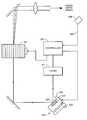
- FIG. 1is schematic of a preferred embodiment of the fiber cassette/alignment block/proximal catheter assembly invention.
- FIG. 2is a simplified view of the proximal end of the embodiment depicted in FIG. 1, showing positioning fibers and active treatment fibers.
- FIG. 3Adepicts a magnified view of the first positioning fiber.
- FIG. 3Bdepicts the data sets produced from the scans shown on FIG. 3 A.
- FIG. 4shows an electro-optical diagram of an embodiment of the present invention.
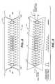
- FIG. 5depicts a non-horizontally positioned fiber array, and illustrative data sets that might be produced by a horizontal alignment scan of a laser beam across the entire array.
- This discussion of a preferred embodiment of the inventionwill use as an example an array of 18 possible fiber channels, numbered 0 to 17 , in a lithographically-etched fiber cassette of the type disclosed in the '700 application and shown in a simplified manner in FIG. 2.
- a fiber cassette of this typeis manufactured as previously described, and the desired number of optical fibers is positioned within the array.
- the active fibers in an arrayare positioned around the center point of the array.
- optical fibers 45 - 50would occupy the fiber channels numbered 6 through 11 .
- the six channels on either side of the active fiber setpreferably would not contain any active fibers.
- deflecting meanssuch as an acousto-optic modulator acousto-optic modulator (AOM)
- AOMacousto-optic modulator
- certain of the active fibersalso may be used to determine the cassette's alignment, instead of using one or more “alignment-dedicated” registration fibers, as long as the fiber cassette/catheter device is positioned so as to permit the detection of transmitted light during the positioning procedure.
- alignment-dedicated registration fibersas long as the fiber cassette/catheter device is positioned so as to permit the detection of transmitted light during the positioning procedure.
- the outermost channels(channel numbers 0 and 17 ) are reserved for use in either determining the actual position of the fiber array with respect to a free laser beam, or ensuring that the fiber array is correctly positioned with respect thereto.
- Each outermost positioning fiberis positioned within the proximal portion of the fiber cassette in the same manner as the active fibers. However, the distal portion of each positioning fiber does not extend down the length of the delivery apparatus, as do the active treatment fibers. Instead, the distal end of each positioning fiber is located such that light transmitted through that fiber can be detected by a light- or energy-sensing means 508 , such as a photodiode or other photosensor positioned in the vicinity of the distal end of the fiber cassette 310 .
- a light- or energy-sensing means 508such as a photodiode or other photosensor positioned in the vicinity of the distal end of the fiber cassette 310 .
- a simple such mechanismmay consist of a small plastic (e.g., ABS, Teflon) alignment block 504 attached to the distal end of the fiber cassette 310 .
- This blockhas a hollow, longitudinal center, through which all of the optical fibers pass, and has a longitudinal slot on one face so that the block 504 can be attached to the fiber cassette 310 around the optical fiber strands.
- the blockmay also have a recessed slot 520 in its proximal face into which the distal end of the fiber cassette is glued.
- a slot about 3 mm deep or greaterhas proven satisfactory to ensure proper positioning in the plastic block.
- a shallower slothas been found to contribute to irregular reproducibility of the cassette-block combination.
- the block 504is wider and higher than the silicon cassette 310 , and much deeper than the recessed attachment slot.
- FIG. 1shows each positioning fiber 500 and 502 terminating within the distal portion of the alignment block 504 .
- All of the fibersare secured in the distal portion of the alignment block with a mixture 518 of glue and a scattering medium, typically microparticles of some material having a refractive index different than—typically higher than—the glue, such as glass, aluminum oxide, sapphire or ground silica.
- the scattering materialscatters the light, which in turn is detected by the photosensor 508 .
- a scattering mediumis used in mixture 518 to desensitize the positioning of the photosensor.
- the fiber cassettecould be constructed so that the positioning fibers exit the cassette/alignment block combination and loop back into the mixture 518 where they are secured, or even loop over to the light detection means 508 .
- the important part of the location of the distal tips of the positioning fibersis that transmitted light is detectable by the light detecting means 508 .
- One other alternativewould be to have a single registration fiber with its proximal end positioned in a first registration position in the cassette and its distal end—essentially a second “proximal” end—looped back to the cassette and mounted in a second registration position. In this construction, light delivered into the first proximal end would be detected when transmitted from the second end, and vice versa, by one or more light detection means in the vicinity of the proximal face of the fiber cassette.
- the distal portion of the alignment block 504also houses a flexible plastic tube 512 (e.g., made of C-Flex) that surrounds the optical fibers 45 - 50 to protect them from accidental breakage.
- the blockis sized to fit within a long alignment channel 522 having one end remote from, and one end proximal to, the pins 248 and 250 for holding the fiber cassette 310 .
- the channel 522may be formed out of a nonyielding material 506 , such as a hard polymer or plastic.
- the channel 522desirably is flanged at both ends, and sized to tight tolerances relative to the block, so that the cassette/block combination can hold a relatively constant position in the channel during travel towards the pins 248 and 250 .
- a usermay insert the cassette/block combination into the entry port 510 , typically on the exterior of the laser unit.
- the external edge of the entry port 510is flanged to direct the cassette and block into the port.
- the usermay need to use some sort of mechanism to push the cassette into place, such as a plastic straw 514 , surrounding tube 512 and fibers 45 - 50 , or a rod or similar pushing means to push the plastic block/cassette down the length of the channel 522 until it reaches the outlet port 524 of the channel. While possible, it is preferable not to directly mechanically couple the pushing means, such as the straw 514 , to the alignment block 504 or the flange 516 .
- Direct mechanical coupling of the pushing meanscan create undesired forces on the fiber cassette and alignment block if the pushing means—extending into the external environment—is knocked or bumped, even accidentally, during a procedure.
- Such external forces, conveyed to the alignment apparatus through the pushing meanscould jar an otherwise satisfactorily-positioned cassette out of alignment or can damage the various structures used to position the fiber array in space and/or the apparatus used to deliver laser energy to a treatment site.
- the outlet port 524is positioned relative to the dowels 248 and 250 on the twin tower assembly (disclosed in the '700 application) such that as the block reaches the far end of the channel, the grooves 224 and 226 in the cassette are roughly aligned with the dowel tips 250 and 248 , respectively.
- the outlet port 524is flanged such that when the cassette 310 was properly positioned between the dowels 248 and 250 , and locked into place with the shutter, the alignment block 504 is no longer constrained by the channel 522 .
- This lack of ultimate constraint by the channel 522helps to prevent the fiber cassette 310 from being stressed if there is an initial slight misalignment of the channel with the dowels tips as the cassette approaches the dowels. (The stress would result from being constrained by both the dowels and the channel at the same time).
- the light detecting means 508 used to assist in the alignment procedure using the positioning fibersmay be located in the proximal flanged area 524 , as shown in FIG. 1.
- Flange 516may be added to the proximal section of the optical fiber sheath (or catheter) so the sheath can be locked into place using a clamp or other locking mechanism, to avoid the device accidentally being pulled out of the laser system during use.
- a means for withdrawing the fiber cassette from between the dowels and back through channel 522such as a flexible but relatively unstretchable nitinol wire (not shown), may be attached to the alignment block 504 to extend between the block and flange 516 , to facilitate removal of the cassette/block combination while minimizing the potential for breaking any of the optical fibers.
- this means for withdrawingshould be flexible enough so as not to transfer to the alignment block, any undesirable external forces, as described above.
- the fiber cassette 310is positioned in the twin-tower apparatus between the dowels 248 and 250 so that the proximal facet 503 lies at least substantially within the focal plane of the optical assembly used to deliver the laser beam to the optical fibers, part of which is shown in FIG. 4 .
- the incoming laser beamis then scanned by the AOM 94 (FIG. 4) from an initial position—typically determined and set by the manufacturer—horizontally across where the first outermost alignment fiber 500 in the fiber optic array should be located. Because the beam is scanned using only the AOM 94 at this point, the beam should travel in a singular planar path across this first position. Scans 1 and 2 shown on FIG.
- 3Aare examples of such initial scans.
- the increment of travel of successive laser beam firings during the scanning procedurewill affect the speed at which the procedure is completed: the smaller the increment of movement (corresponding to the increment in the angular deflection of the beam produced by the AOM), the longer the procedure will take; the larger the incremental movement, the shorter is the period of time required to conduct the scan.
- the more movement per incrementthe potentially less accurate is the ultimate alignment.
- the usershould pick increments to best serve his needs depending on the desired degree of accuracy and speed.
- the path length of the first scancan either be preset to be a certain distance (equaling a certain number of increments) that should be greater than the optical fiber width, or can be determined by the width of the data set produced, and thus can be controlled to terminate after no more light is transmitted down fiber 500 .
- FIG. 3Bdepicts two typical data sets generated from scans across a positioning fiber 500 . Each curve represents the relationship between power transmitted through the positioning fiber and detected by the photosensor 508 against incremental position of the laser beam impinging upon the positioning fiber.
- Scan 2depicts a scan across the centerline of the fiber
- Scan 1represents a scan across a shorter chord of the same fiber.
- the width (full width at half maximum, or FWHM) of each data setprovides information about the width of the portion of the fiber scanned. As shown by the data set corresponding to Scan 1 , the closer the scan is to the edge of the fiber, the more interference with light transmission there is, the narrower the data curve produced and the smaller the maximum degree of light transmission detected.
- the shapes of the curves in FIG. 3Bare dependent upon the cross-sectional size of the laser beam relative to the fiber diameter.
- the more vertical portions of the Scan 2 data setevidence that the spot size 501 of the laser beam is much smaller than the diameter of the fiber 500 being scanned (e.g., a spot size of less than about 15 microns for a fiber diameter of greater than about 50 microns). If the beam diameter were to approach the fiber diameter, the more interference would be generated at the edges of the fiber during the positioning scan, and thus the less steep would be the transition zones of the Scan 2 data set. Alternatively, as the ratio of the spot size diameter to fiber diameter approaches zero, the steeper would be the transition zones of a data set. If no transmitted light is detected during an entire scan across fiber 500 , another scan or scans may be conducted, or the fiber cassette may be rejected out of hand as unusable.
- the alignment proceduremay be stopped at this point, the center of the data set determined, and the laser controlled to operate so that the laser beam will impinge upon that data set centerpoint.
- the centerpoint of the first scanis actually the fiber's centerpoint, so as to ensure maximum transmission of the laser beam through the active fibers once the device is activated for treatment, unless the width of the scan's data set equals or exceeds an acceptable width indicating that the scan was conducted at least substantially close to, if not directly upon, the fiber's diameter.
- the alternatives for scanning the first positioning fiber multiple timesare many, including multiple vertically-indexed horizontal scans across the face of the fiber, another single scan vertically across the face of the fiber, multiple horizontally-indexed vertical scans, or a combination of any of these.
- the laser beam firstcan be vertically adjusted so that the second horizontal scan can be performed on a chord different from the first scan and its data compared to the data of the first scan.
- vertical incrementsmay be chosen by taking into account the same considerations as above.
- Vertical adjusting means 526such as a kinematic mount, shown in FIG. 4, achieves vertical adjustment of the laser beam delivered to the fiber array by adjusting the angle of the mirror 530 attached to vertical adjustment means 526 .
- a kinematic mountis preferred as vertical adjustment means 526 , any mechanism that can incrementally adjust the angle of a mirror may be used, such as a galvanometer.
- another AOMcould be used to deflect vertically the beam.
- the vertical adjustment means 526may be adjusted manually by adjusting one of the adjustment screws 532
- automatic adjustmentmay be achieved by having the pertinent adjustment screw impinge upon a piezoelectric stack 534 .
- This stackwill expand as voltage is applied, thereby biasing the adjustment screw 532 , incrementally changing the angle of the mount table, and so changing the angle of the mirror 530 .
- the higher the voltage applied to the piezoelectric stackthe greater the degree of expansion and thus the change in the angle of the mirror 530 .
- Voltagesare selected to adjust the mirror so that the laser beam is adjusted the desired increment. Once the laser beam is vertically adjusted to the desired height, the horizontal scan is repeated, either in the same direction as the first scan or backwards across the fiber, thereby producing another data set of detected transmitted power versus distance traveled (of AOM angular deflection).
- a vertical scanmay be conducted of the same fiber.
- a vertical scanmay be conducted by repeatedly incrementally adjusting the angle of mirror 530 by adjusting the voltage delivered to the piezoelectric stack 534 , and so moving the laser beam vertically down the fiber face in a manner similar to how the beam was moved horizontally across the face of the fiber using the AOM.
- an AOMtypically has a wide angular range of laser beam deflection, such that it can scan a laser beam across a single optical fiber face without difficulty
- vertical movement of a laser beam through expansion of a piezoelectric stackis limited by the size of the stack. The longer the desired vertical path of beam movement, the larger must be the piezoelectric stack.
- the kinematic mount 526is depicted with a modification 528 to accommodate a long piezoelectric stack 534 .
- the midpoint of the first outermost fibershould be known. If desired, another scan can verify that the center point of the fiber has been accurately located by, e.g., performing another horizontal scan through the midpoint of the vertical scan and verifying that the width of the data set generated corresponds to the expected value for the width of the fiber being scanned.
- the location of the centerpoint of the first fiberhas been found. Because the distance between adjacent centerpoints of each channel in the fiber cassette 310 —and thus the distance between the centerpoints of adjacent fibers—is known (preferably about 75 microns), due to the precise lithographic etching process used to manufacture the cassette, and because the controller 103 is aware (through manual data input or from reading a microchip on the catheter) of the number and spatial arrangement of active fibers in the cassette, the distances from the positioning fiber's centerpoint to the active fibers' centerpoints are known. However, accurate delivery of a free laser beam to each of the active fibers cannot yet be assured, due to the fact that the fiber cassette 310 as a whole may not be truly horizontal, as depicted in FIG.
- FIG. 5depicts an example in which the fiber cassette is tilted an angle a from horizontal, such that a scan of the laser beam on a plane 540 corresponding to the center point of alignment fiber 500 would in fact barely impinge upon fiber 50 , and would not impinge at all upon registration fiber 502 , indicating the cassette is out of alignment. Note that although scans are depicted for each fiber in the array (for illustrative purposes), only fibers 500 and 502 would be scanned in this preferred embodiment of the invention.
- another positioning scanning proceduremay be conducted on the fiber 502 occupying the other outermost position in the array. Verifying the position of this second positioning fiber 502 can be conducted in any number of ways, including any number of horizontal and vertical scans, as described above. However, since the actual centerpoint of fiber 502 relative to the fiber cassette will be known based on the known etch dimensions, it may be desirable only to determine whether the fiber cassette 310 is, in fact, horizontal or, if not, to what extent it is tilted.
- One method of verifying whether the entire fiber array is substantially horizontalis to scan the second outermost fiber 502 with a laser beam on the same level as the centerpoint of the first outermost fiber—i.e., using the AOM with the piezoelectric stack 526 adjusted to provide a vertical setting corresponding to the vertical position of the centerpoint of the first positioning fiber 500 . If the width of the data set produced from this scan falls within a certain tolerance of the actual width of the optical fiber, then the array can be deemed to be horizontal and no further scans may be necessary. Within a “certain tolerance” of the actual width of the optical fiber is acceptable because of the difference in sizes between the width of the laser beam itself and the width of an optical fiber. Since a typical laser beam does not necessarily have to impinge exactly upon the centerpoint for its energy to be delivered to the fiber without appreciable losses, slight tilt (e.g., on the order of microns) of the fiber cassette may be tolerable.
- the centerpoint of the fibercan be located as described above using one or more horizontal or vertical scans. Once the location of the centerpoint of the second outermost fiber is known, the relative horizontal and vertical positioning of each of the outermost fibers is known, and thus the relative horizontal and vertical positions of each of the optical fibers in the array will be known from trigonometry.
- the laser beamcan then be delivered to each of the optical fibers in the array by the controller 103 adjusting both the horizontal distance from the centerpoint of the first outermost fiber (with the AOM) and the vertical distance from the centerpoint of the first outermost fiber (with the piezoelectric stack on the kinematic mount). Note, however, that the piezoelectric stack will limit the speed with which the laser beam can be adjusted between adjacent fibers, since the expansion of the stack takes a longer period of time than is required for the AOM to change the angle of the scanning beam.
- any other means for scanning the laser beamcan be used to accurately vertically position the laser beam on each fiber, such as a second AOM, a galvanometer (with its speed limitations), or a polygonal mirror.
- each laser beamcan be aligned with the fiber array in the manner described herein, to ensure accurate delivery of each beam to each active fiber in the array.
- the alignment methods described and disclosed hereinmay be implemented through any number of hardware and/or software arrangements, which are within the realm of skill in the art.
- a major advantage of this procedureis that the location of each fiber is determined by analyzing not light backscattered from a fiber surface, but by analyzing power actually transmitted through the fiber.
- the detection of backscattered light, and the resulting analysis of whether the backscatter is due to a surface of the cassette or hardened glue or the glue-fiber interface or the fiber surface itself, whether or not well polished,is often not straightforward. Detection of transmitted light to determine accurate alignment, however, obviously depends on transmission of light through the fiber and thus eliminates many of the variables that affect analysis of backscattered light for alignment.
Landscapes
- Physics & Mathematics (AREA)
- Health & Medical Sciences (AREA)
- General Physics & Mathematics (AREA)
- Optics & Photonics (AREA)
- Life Sciences & Earth Sciences (AREA)
- Surgery (AREA)
- Electromagnetism (AREA)
- Heart & Thoracic Surgery (AREA)
- Otolaryngology (AREA)
- Chemical & Material Sciences (AREA)
- Crystallography & Structural Chemistry (AREA)
- Engineering & Computer Science (AREA)
- Biomedical Technology (AREA)
- Nuclear Medicine, Radiotherapy & Molecular Imaging (AREA)
- Medical Informatics (AREA)
- Molecular Biology (AREA)
- Animal Behavior & Ethology (AREA)
- General Health & Medical Sciences (AREA)
- Public Health (AREA)
- Veterinary Medicine (AREA)
- Optical Couplings Of Light Guides (AREA)
- Mechanical Coupling Of Light Guides (AREA)
Abstract
Description
Claims (5)
Priority Applications (5)
| Application Number | Priority Date | Filing Date | Title |
|---|---|---|---|
| US09/299,415US6339470B1 (en) | 1999-04-26 | 1999-04-26 | Apparatus and method for aligning an energy beam |
| PCT/US2000/009345WO2000065396A2 (en) | 1999-04-26 | 2000-04-06 | Fiber array connection and scanning alignment method for endoscope application |
| EP00921887AEP1173787A2 (en) | 1999-04-26 | 2000-04-06 | Fiber array connection and scanning alignment method for endoscope application |
| AU42147/00AAU4214700A (en) | 1999-04-26 | 2000-04-06 | Apparatus and method for aligning an energy beam |
| JP2000614080AJP2003517628A (en) | 1999-04-26 | 2000-04-06 | Apparatus and method for aligning energy beams |
Applications Claiming Priority (1)
| Application Number | Priority Date | Filing Date | Title |
|---|---|---|---|
| US09/299,415US6339470B1 (en) | 1999-04-26 | 1999-04-26 | Apparatus and method for aligning an energy beam |
Publications (1)
| Publication Number | Publication Date |
|---|---|
| US6339470B1true US6339470B1 (en) | 2002-01-15 |
Family
ID=23154701
Family Applications (1)
| Application Number | Title | Priority Date | Filing Date |
|---|---|---|---|
| US09/299,415Expired - Fee RelatedUS6339470B1 (en) | 1999-04-26 | 1999-04-26 | Apparatus and method for aligning an energy beam |
Country Status (5)
| Country | Link |
|---|---|
| US (1) | US6339470B1 (en) |
| EP (1) | EP1173787A2 (en) |
| JP (1) | JP2003517628A (en) |
| AU (1) | AU4214700A (en) |
| WO (1) | WO2000065396A2 (en) |
Cited By (23)
| Publication number | Priority date | Publication date | Assignee | Title |
|---|---|---|---|---|
| US20030020913A1 (en)* | 2001-07-27 | 2003-01-30 | Richard Jenkin A. | System and method for optical multiplexing and/or demultiplexing |
| US20030130650A1 (en)* | 2001-12-19 | 2003-07-10 | Ran Yaron | Miniature refrigeration system for cryothermal ablation catheter |
| WO2004003625A1 (en) | 2002-06-28 | 2004-01-08 | Clvr Pty Ltd | Scanning device and method of scanning an optical beam over a surface |
| US9980789B2 (en) | 2014-12-05 | 2018-05-29 | Convergent Dental, Inc. | System and methods for alignment of a laser beam |
| US11517713B2 (en) | 2019-06-26 | 2022-12-06 | Boston Scientific Scimed, Inc. | Light guide protection structures for plasma system to disrupt vascular lesions |
| US11583339B2 (en) | 2019-10-31 | 2023-02-21 | Bolt Medical, Inc. | Asymmetrical balloon for intravascular lithotripsy device and method |
| US11648057B2 (en) | 2021-05-10 | 2023-05-16 | Bolt Medical, Inc. | Optical analyzer assembly with safety shutdown system for intravascular lithotripsy device |
| US11660427B2 (en) | 2019-06-24 | 2023-05-30 | Boston Scientific Scimed, Inc. | Superheating system for inertial impulse generation to disrupt vascular lesions |
| US11672585B2 (en) | 2021-01-12 | 2023-06-13 | Bolt Medical, Inc. | Balloon assembly for valvuloplasty catheter system |
| US11672599B2 (en) | 2020-03-09 | 2023-06-13 | Bolt Medical, Inc. | Acoustic performance monitoring system and method within intravascular lithotripsy device |
| US11707323B2 (en) | 2020-04-03 | 2023-07-25 | Bolt Medical, Inc. | Electrical analyzer assembly for intravascular lithotripsy device |
| US11717139B2 (en) | 2019-06-19 | 2023-08-08 | Bolt Medical, Inc. | Plasma creation via nonaqueous optical breakdown of laser pulse energy for breakup of vascular calcium |
| US11806075B2 (en) | 2021-06-07 | 2023-11-07 | Bolt Medical, Inc. | Active alignment system and method for laser optical coupling |
| US11819229B2 (en) | 2019-06-19 | 2023-11-21 | Boston Scientific Scimed, Inc. | Balloon surface photoacoustic pressure wave generation to disrupt vascular lesions |
| US11839391B2 (en) | 2021-12-14 | 2023-12-12 | Bolt Medical, Inc. | Optical emitter housing assembly for intravascular lithotripsy device |
| US11903642B2 (en) | 2020-03-18 | 2024-02-20 | Bolt Medical, Inc. | Optical analyzer assembly and method for intravascular lithotripsy device |
| US12016610B2 (en) | 2020-12-11 | 2024-06-25 | Bolt Medical, Inc. | Catheter system for valvuloplasty procedure |
| US12102384B2 (en) | 2019-11-13 | 2024-10-01 | Bolt Medical, Inc. | Dynamic intravascular lithotripsy device with movable energy guide |
| US12207870B2 (en) | 2020-06-15 | 2025-01-28 | Boston Scientific Scimed, Inc. | Spectroscopic tissue identification for balloon intravascular lithotripsy guidance |
| US12274497B2 (en) | 2019-12-18 | 2025-04-15 | Bolt Medical, Inc. | Multiplexer for laser-driven intravascular lithotripsy device |
| US12274485B2 (en) | 2021-01-12 | 2025-04-15 | Bolt Medical, Inc. | Balloon assembly for valvuloplasty catheter system |
| US12295654B2 (en) | 2020-06-03 | 2025-05-13 | Boston Scientific Scimed, Inc. | System and method for maintaining balloon integrity within intravascular lithotripsy device with plasma generator |
| US12402946B2 (en) | 2019-06-19 | 2025-09-02 | Boston Scientific Scimed, Inc. | Breakdown of laser pulse energy for breakup of vascular calcium |
Families Citing this family (4)
| Publication number | Priority date | Publication date | Assignee | Title |
|---|---|---|---|---|
| US6373644B1 (en) | 1999-11-15 | 2002-04-16 | Axsun Technologies, Inc. | Micro optical bench component clip structures |
| US6409395B1 (en) | 2001-05-24 | 2002-06-25 | Axsun Technologies, Inc. | Method for fabricating fiber arrays with precision fiber core-to-core pitch and height |
| US6665487B2 (en) | 2001-05-24 | 2003-12-16 | Axsun Technologies, Inc. | Precision alignment feature using a rod with controlled diameter in a silicon V-groove array |
| EP3536378A1 (en)* | 2018-03-08 | 2019-09-11 | Koninklijke Philips N.V. | A device configured to be aligned with respect to a medical system |
Citations (33)
| Publication number | Priority date | Publication date | Assignee | Title |
|---|---|---|---|---|
| US4084182A (en) | 1974-07-01 | 1978-04-11 | Laser Video, Inc. | Multi-beam modulator and method for light beam displays |
| US4538613A (en) | 1983-01-17 | 1985-09-03 | Larry Rosenberg | Coherent beam coupler system |
| EP0249237A2 (en) | 1986-06-13 | 1987-12-16 | Sumitomo Electric Industries Limited | Optical connector ferrule |
| US4798449A (en) | 1986-04-25 | 1989-01-17 | Societe Francaise D'equipments Pour La Navigation Aerienne & Societe Automates Et Automatismes | Polychromatic acousto-optical deflector |
| US4875969A (en) | 1988-10-07 | 1989-10-24 | Eastman Kodak Company | Method of making a fiber optic array |
| US4880494A (en) | 1988-10-07 | 1989-11-14 | Eastman Kodak Company | Method of making a fiber optic array |
| US4911526A (en) | 1988-10-07 | 1990-03-27 | Eastman Kodak Company | Fiber optic array |
| US4913142A (en) | 1985-03-22 | 1990-04-03 | Massachusetts Institute Of Technology | Catheter for laser angiosurgery |
| US4923275A (en) | 1988-10-07 | 1990-05-08 | Eastman Kodak Company | Fiber optic array |
| US4957342A (en) | 1989-11-20 | 1990-09-18 | Gte Laboratories Incorporated | Single-mode optical fiber array package for optoelectronic components |
| US4994059A (en)* | 1986-05-09 | 1991-02-19 | Gv Medical, Inc. | Laser catheter feedback system |
| WO1991002994A1 (en) | 1989-08-24 | 1991-03-07 | Raychem Corporation | Optical fiber connector which provides a high signal return loss |
| US5024504A (en) | 1989-11-20 | 1991-06-18 | Gte Laboratories Incorporated | Method of aligning and packaging an optoelectronic component with a single-mode optical fiber array |
| US5034010A (en) | 1985-03-22 | 1991-07-23 | Massachusetts Institute Of Technology | Optical shield for a laser catheter |
| US5121457A (en) | 1991-05-21 | 1992-06-09 | Gte Laboratories Incorporated | Method for coupling laser array to optical fiber array |
| US5127068A (en) | 1990-11-16 | 1992-06-30 | Spectra-Physics, Inc. | Apparatus for coupling a multiple emitter laser diode to a multimode optical fiber |
| US5153782A (en) | 1989-12-22 | 1992-10-06 | Agfa Gevaert Ag | Process for the coincident deflection of light of differing wavelengths |
| US5192278A (en) | 1985-03-22 | 1993-03-09 | Massachusetts Institute Of Technology | Multi-fiber plug for a laser catheter |
| US5209748A (en) | 1989-08-24 | 1993-05-11 | S.L.T. Japan Co., Ltd. | Laser light irradiation apparatus |
| US5214730A (en) | 1991-05-13 | 1993-05-25 | Nippon Telegraph And Telephone Corporation | Multifiber optical connector plug with low reflection and low insertion loss |
| EP0574686A2 (en) | 1992-05-13 | 1993-12-22 | The Spectranetics Corporation | Linear scan method and system for cloupling energy into an optical fiber bundle |
| US5290277A (en) | 1992-04-03 | 1994-03-01 | Angeion Corporation | Multi-fiber linear array laser catheter connector |
| JPH0727942A (en) | 1993-07-12 | 1995-01-31 | Nippon Telegr & Teleph Corp <Ntt> | Fiber connect module |
| US5394495A (en) | 1994-02-22 | 1995-02-28 | E. I. Du Pont De Nemours And Company | Optical waveguide connectors and methods of making same |
| US5420954A (en) | 1993-05-24 | 1995-05-30 | Photonics Research Incorporated | Parallel optical interconnect |
| US5519798A (en) | 1994-08-15 | 1996-05-21 | At&T Corp. | Optical fiber connector including V-groove/pin alignment means |
| US5559915A (en) | 1995-04-13 | 1996-09-24 | Lucent Technologies Inc. | Apparatuses and methods for aligning an optical fiber array with an optical integrated circuit assembly |
| US5598494A (en) | 1995-10-23 | 1997-01-28 | The United States Of America As Represented By The Secretary Of The Army | Multi-channel fiber optic connector |
| US5620634A (en) | 1995-08-17 | 1997-04-15 | Lucent Technologies Inc. | Method of making fiber waveguide connectors |
| US5751835A (en) | 1995-10-04 | 1998-05-12 | Topping; Allen | Method and apparatus for the automated identification of individuals by the nail beds of their fingernails |
| US5859947A (en)* | 1994-10-02 | 1999-01-12 | Ramot University Authority For Applied Research & Industrial Development Ltd. | Positioning devices and a method and positioning device for aligning an optical fiber with an optical beam |
| JPH1114864A (en) | 1997-06-20 | 1999-01-22 | Furukawa Electric Co Ltd:The | Method and apparatus for identifying core position during alignment of optical component |
| US5946099A (en)* | 1996-08-30 | 1999-08-31 | Ngk Insulators, Ltd. | Method of measuring positions of optical transmission members |
- 1999
- 1999-04-26USUS09/299,415patent/US6339470B1/ennot_activeExpired - Fee Related
- 2000
- 2000-04-06JPJP2000614080Apatent/JP2003517628A/enactivePending
- 2000-04-06AUAU42147/00Apatent/AU4214700A/ennot_activeAbandoned
- 2000-04-06WOPCT/US2000/009345patent/WO2000065396A2/ennot_activeApplication Discontinuation
- 2000-04-06EPEP00921887Apatent/EP1173787A2/ennot_activeWithdrawn
Patent Citations (35)
| Publication number | Priority date | Publication date | Assignee | Title |
|---|---|---|---|---|
| US4084182A (en) | 1974-07-01 | 1978-04-11 | Laser Video, Inc. | Multi-beam modulator and method for light beam displays |
| US4538613A (en) | 1983-01-17 | 1985-09-03 | Larry Rosenberg | Coherent beam coupler system |
| US5192278A (en) | 1985-03-22 | 1993-03-09 | Massachusetts Institute Of Technology | Multi-fiber plug for a laser catheter |
| US5034010A (en) | 1985-03-22 | 1991-07-23 | Massachusetts Institute Of Technology | Optical shield for a laser catheter |
| US4913142A (en) | 1985-03-22 | 1990-04-03 | Massachusetts Institute Of Technology | Catheter for laser angiosurgery |
| US4798449A (en) | 1986-04-25 | 1989-01-17 | Societe Francaise D'equipments Pour La Navigation Aerienne & Societe Automates Et Automatismes | Polychromatic acousto-optical deflector |
| US4994059A (en)* | 1986-05-09 | 1991-02-19 | Gv Medical, Inc. | Laser catheter feedback system |
| EP0249237A2 (en) | 1986-06-13 | 1987-12-16 | Sumitomo Electric Industries Limited | Optical connector ferrule |
| US4923275A (en) | 1988-10-07 | 1990-05-08 | Eastman Kodak Company | Fiber optic array |
| US4911526A (en) | 1988-10-07 | 1990-03-27 | Eastman Kodak Company | Fiber optic array |
| US4880494A (en) | 1988-10-07 | 1989-11-14 | Eastman Kodak Company | Method of making a fiber optic array |
| US4875969A (en) | 1988-10-07 | 1989-10-24 | Eastman Kodak Company | Method of making a fiber optic array |
| WO1991002994A1 (en) | 1989-08-24 | 1991-03-07 | Raychem Corporation | Optical fiber connector which provides a high signal return loss |
| US5209748A (en) | 1989-08-24 | 1993-05-11 | S.L.T. Japan Co., Ltd. | Laser light irradiation apparatus |
| US4957342A (en) | 1989-11-20 | 1990-09-18 | Gte Laboratories Incorporated | Single-mode optical fiber array package for optoelectronic components |
| US5024504A (en) | 1989-11-20 | 1991-06-18 | Gte Laboratories Incorporated | Method of aligning and packaging an optoelectronic component with a single-mode optical fiber array |
| US5153782A (en) | 1989-12-22 | 1992-10-06 | Agfa Gevaert Ag | Process for the coincident deflection of light of differing wavelengths |
| US5127068A (en) | 1990-11-16 | 1992-06-30 | Spectra-Physics, Inc. | Apparatus for coupling a multiple emitter laser diode to a multimode optical fiber |
| US5214730A (en) | 1991-05-13 | 1993-05-25 | Nippon Telegraph And Telephone Corporation | Multifiber optical connector plug with low reflection and low insertion loss |
| US5121457A (en) | 1991-05-21 | 1992-06-09 | Gte Laboratories Incorporated | Method for coupling laser array to optical fiber array |
| US5290277A (en) | 1992-04-03 | 1994-03-01 | Angeion Corporation | Multi-fiber linear array laser catheter connector |
| US5400428A (en) | 1992-05-13 | 1995-03-21 | Spectranetics Corporation | Method and apparatus for linearly scanning energy over an optical fiber array and coupler for coupling energy to the optical fiber array |
| EP0574686A2 (en) | 1992-05-13 | 1993-12-22 | The Spectranetics Corporation | Linear scan method and system for cloupling energy into an optical fiber bundle |
| US5420954A (en) | 1993-05-24 | 1995-05-30 | Photonics Research Incorporated | Parallel optical interconnect |
| US5631988A (en) | 1993-05-24 | 1997-05-20 | Vixel Corporation | Parallel optical interconnect |
| JPH0727942A (en) | 1993-07-12 | 1995-01-31 | Nippon Telegr & Teleph Corp <Ntt> | Fiber connect module |
| US5394495A (en) | 1994-02-22 | 1995-02-28 | E. I. Du Pont De Nemours And Company | Optical waveguide connectors and methods of making same |
| US5519798A (en) | 1994-08-15 | 1996-05-21 | At&T Corp. | Optical fiber connector including V-groove/pin alignment means |
| US5859947A (en)* | 1994-10-02 | 1999-01-12 | Ramot University Authority For Applied Research & Industrial Development Ltd. | Positioning devices and a method and positioning device for aligning an optical fiber with an optical beam |
| US5559915A (en) | 1995-04-13 | 1996-09-24 | Lucent Technologies Inc. | Apparatuses and methods for aligning an optical fiber array with an optical integrated circuit assembly |
| US5620634A (en) | 1995-08-17 | 1997-04-15 | Lucent Technologies Inc. | Method of making fiber waveguide connectors |
| US5751835A (en) | 1995-10-04 | 1998-05-12 | Topping; Allen | Method and apparatus for the automated identification of individuals by the nail beds of their fingernails |
| US5598494A (en) | 1995-10-23 | 1997-01-28 | The United States Of America As Represented By The Secretary Of The Army | Multi-channel fiber optic connector |
| US5946099A (en)* | 1996-08-30 | 1999-08-31 | Ngk Insulators, Ltd. | Method of measuring positions of optical transmission members |
| JPH1114864A (en) | 1997-06-20 | 1999-01-22 | Furukawa Electric Co Ltd:The | Method and apparatus for identifying core position during alignment of optical component |
Non-Patent Citations (6)
| Title |
|---|
| "Wave Optics Specialty Fiber Optic Products" 1997 catalog, p. 32. |
| Fiberoptic Product News, "The Global Source for Fiberoptic Technology and Applications" (unknown date), two pages. |
| International Search Report for corresponding PCT application No. PCT/US00/09345 dated Nov. 13, 2000. |
| International Search Report for PCT/US00/09345 dated Aug. 21, 2000. |
| J. Senior, Optical Fiber Comunications: Principles and Practice, pp. 144-173, (C)1985 Prentice-Hall International., Inc., London. |
| J. Senior, Optical Fiber Comunications: Principles and Practice, pp. 144-173, ©1985 Prentice-Hall International., Inc., London. |
Cited By (34)
| Publication number | Priority date | Publication date | Assignee | Title |
|---|---|---|---|---|
| US6847450B2 (en)* | 2001-07-27 | 2005-01-25 | Oplink Communications, Inc. | System and method for optical multiplexing and/or demultiplexing |
| US20030020913A1 (en)* | 2001-07-27 | 2003-01-30 | Richard Jenkin A. | System and method for optical multiplexing and/or demultiplexing |
| US7615048B2 (en) | 2001-12-19 | 2009-11-10 | Ran Yaron | Engine with liquid piston |
| US6949094B2 (en) | 2001-12-19 | 2005-09-27 | Ran Yaron | Miniature refrigeration system for cryothermal ablation catheter |
| US20050277914A1 (en)* | 2001-12-19 | 2005-12-15 | Ran Yaron | Miniature refrigeration system for cryothermal ablation catheter |
| US20100057066A1 (en)* | 2001-12-19 | 2010-03-04 | Ran Yaron | Apparatus for and method of producing an ultrasonic signal |
| US20030130650A1 (en)* | 2001-12-19 | 2003-07-10 | Ran Yaron | Miniature refrigeration system for cryothermal ablation catheter |
| WO2004003625A1 (en) | 2002-06-28 | 2004-01-08 | Clvr Pty Ltd | Scanning device and method of scanning an optical beam over a surface |
| US9980789B2 (en) | 2014-12-05 | 2018-05-29 | Convergent Dental, Inc. | System and methods for alignment of a laser beam |
| US10470843B2 (en) | 2014-12-05 | 2019-11-12 | Convergent Dental, Inc. | Systems and methods for alignment of a laser beam |
| US11717139B2 (en) | 2019-06-19 | 2023-08-08 | Bolt Medical, Inc. | Plasma creation via nonaqueous optical breakdown of laser pulse energy for breakup of vascular calcium |
| US11819229B2 (en) | 2019-06-19 | 2023-11-21 | Boston Scientific Scimed, Inc. | Balloon surface photoacoustic pressure wave generation to disrupt vascular lesions |
| US12402946B2 (en) | 2019-06-19 | 2025-09-02 | Boston Scientific Scimed, Inc. | Breakdown of laser pulse energy for breakup of vascular calcium |
| US11660427B2 (en) | 2019-06-24 | 2023-05-30 | Boston Scientific Scimed, Inc. | Superheating system for inertial impulse generation to disrupt vascular lesions |
| US11517713B2 (en) | 2019-06-26 | 2022-12-06 | Boston Scientific Scimed, Inc. | Light guide protection structures for plasma system to disrupt vascular lesions |
| US12280223B2 (en) | 2019-06-26 | 2025-04-22 | Boston Scientific Scimed, Inc. | Focusing element for plasma system to disrupt vascular lesions |
| US12186499B2 (en) | 2019-06-26 | 2025-01-07 | Boston Scientific Scimed, Inc. | Light guide protection structures for plasma system to disrupt vascular lesions |
| US12311124B2 (en) | 2019-06-26 | 2025-05-27 | Boston Scientific Scimed, Inc. | Fortified balloon inflation fluid for plasma system to disrupt vascular lesions |
| US11911574B2 (en) | 2019-06-26 | 2024-02-27 | Boston Scientific Scimed, Inc. | Fortified balloon inflation fluid for plasma system to disrupt vascular lesions |
| US11583339B2 (en) | 2019-10-31 | 2023-02-21 | Bolt Medical, Inc. | Asymmetrical balloon for intravascular lithotripsy device and method |
| US12102384B2 (en) | 2019-11-13 | 2024-10-01 | Bolt Medical, Inc. | Dynamic intravascular lithotripsy device with movable energy guide |
| US12274497B2 (en) | 2019-12-18 | 2025-04-15 | Bolt Medical, Inc. | Multiplexer for laser-driven intravascular lithotripsy device |
| US11672599B2 (en) | 2020-03-09 | 2023-06-13 | Bolt Medical, Inc. | Acoustic performance monitoring system and method within intravascular lithotripsy device |
| US11903642B2 (en) | 2020-03-18 | 2024-02-20 | Bolt Medical, Inc. | Optical analyzer assembly and method for intravascular lithotripsy device |
| US11707323B2 (en) | 2020-04-03 | 2023-07-25 | Bolt Medical, Inc. | Electrical analyzer assembly for intravascular lithotripsy device |
| US12295654B2 (en) | 2020-06-03 | 2025-05-13 | Boston Scientific Scimed, Inc. | System and method for maintaining balloon integrity within intravascular lithotripsy device with plasma generator |
| US12207870B2 (en) | 2020-06-15 | 2025-01-28 | Boston Scientific Scimed, Inc. | Spectroscopic tissue identification for balloon intravascular lithotripsy guidance |
| US12016610B2 (en) | 2020-12-11 | 2024-06-25 | Bolt Medical, Inc. | Catheter system for valvuloplasty procedure |
| US11672585B2 (en) | 2021-01-12 | 2023-06-13 | Bolt Medical, Inc. | Balloon assembly for valvuloplasty catheter system |
| US12274485B2 (en) | 2021-01-12 | 2025-04-15 | Bolt Medical, Inc. | Balloon assembly for valvuloplasty catheter system |
| US11648057B2 (en) | 2021-05-10 | 2023-05-16 | Bolt Medical, Inc. | Optical analyzer assembly with safety shutdown system for intravascular lithotripsy device |
| US11806075B2 (en) | 2021-06-07 | 2023-11-07 | Bolt Medical, Inc. | Active alignment system and method for laser optical coupling |
| US12232753B2 (en) | 2021-12-14 | 2025-02-25 | Bolt Medical, Inc. | Optical emitter housing assembly for intravascular lithotripsy device |
| US11839391B2 (en) | 2021-12-14 | 2023-12-12 | Bolt Medical, Inc. | Optical emitter housing assembly for intravascular lithotripsy device |
Also Published As
| Publication number | Publication date |
|---|---|
| AU4214700A (en) | 2000-11-10 |
| JP2003517628A (en) | 2003-05-27 |
| EP1173787A2 (en) | 2002-01-23 |
| WO2000065396A3 (en) | 2001-02-15 |
| WO2000065396A2 (en) | 2000-11-02 |
Similar Documents
| Publication | Publication Date | Title |
|---|---|---|
| US6339470B1 (en) | Apparatus and method for aligning an energy beam | |
| US5579422A (en) | Apparatus for coupling a multiple emitter laser diode to a multimode optical fiber | |
| JP5582588B2 (en) | Fiber optic interconnect device | |
| US5383199A (en) | Apparatus and method for optically controlling the output energy of a pulsed laser source | |
| EP3289397B1 (en) | Expanded-beam ferrule with high coupling efficiency for optical interface devices | |
| US6253007B1 (en) | Method and apparatus for connecting optical fibers | |
| US20020131699A1 (en) | Collimator array and method and system for aligning optical fibers to a lens array | |
| US20030174419A1 (en) | Optical assembly and method of making | |
| US7267260B2 (en) | Apparatus for holding a fiber array | |
| US5040862A (en) | Method of trimming optical power | |
| US12379545B2 (en) | Method and system for aligning and positioning an optical fiber and microlens array | |
| JPH09113832A (en) | Optical scanning device | |
| US6721479B2 (en) | Fiber collimator | |
| KR100763115B1 (en) | Fiber alignment structures | |
| US6512868B1 (en) | Precision fiber optic collimator | |
| US20230161110A1 (en) | Optical fiber support structure | |
| EP0511805B1 (en) | Coupler for a laser delivery system | |
| US7695202B1 (en) | Visual laser diode to fiber coupling system | |
| US20010020164A1 (en) | Apparatus for delivering radiation energy | |
| US8045164B2 (en) | Position finding system and method for use in aligning laser device with an optical fiber | |
| US6904223B1 (en) | Tilted-translation variable optical attenuator | |
| US6666588B1 (en) | Collimator array having precisely aligned optical beams and method of assembling same | |
| US20140117191A1 (en) | Apparatus and method for positioning an optical device | |
| JP2002299746A (en) | Optical device | |
| US20020064343A1 (en) | Optical coupling device with anisotropic light-guiding member |
Legal Events
| Date | Code | Title | Description |
|---|---|---|---|
| AS | Assignment | Owner name:ENDOVASIX, INC., CALIFORNIA Free format text:ASSIGNMENT OF ASSIGNORS INTEREST;ASSIGNORS:PAPADEMETRIOU, STEPHANOS;ESCH, VICTOR C.;REEL/FRAME:010074/0113 Effective date:19990614 | |
| REMI | Maintenance fee reminder mailed | ||
| FEPP | Fee payment procedure | Free format text:PAYER NUMBER DE-ASSIGNED (ORIGINAL EVENT CODE: RMPN); ENTITY STATUS OF PATENT OWNER: LARGE ENTITY Free format text:PAYOR NUMBER ASSIGNED (ORIGINAL EVENT CODE: ASPN); ENTITY STATUS OF PATENT OWNER: LARGE ENTITY | |
| AS | Assignment | Owner name:SELVA MEDICAL, INC., CALIFORNIA Free format text:ASSIGNMENT OF ASSIGNORS INTEREST;ASSIGNOR:ENDOVASIX, INC.;REEL/FRAME:017176/0032 Effective date:20050311 | |
| FPAY | Fee payment | Year of fee payment:4 | |
| SULP | Surcharge for late payment | ||
| FEPP | Fee payment procedure | Free format text:PAT HOLDER NO LONGER CLAIMS SMALL ENTITY STATUS, ENTITY STATUS SET TO UNDISCOUNTED (ORIGINAL EVENT CODE: STOL); ENTITY STATUS OF PATENT OWNER: LARGE ENTITY | |
| AS | Assignment | Owner name:GORE ENTERPRISE HOLDINGS, INC., DELAWARE Free format text:ASSIGNMENT OF ASSIGNORS INTEREST;ASSIGNOR:W.L. GORE & ASSOCIATES, INC.;REEL/FRAME:019881/0046 Effective date:20070917 | |
| FPAY | Fee payment | Year of fee payment:8 | |
| AS | Assignment | Owner name:W. L. GORE & ASSOCIATES, INC., DELAWARE Free format text:ASSIGNMENT OF ASSIGNORS INTEREST;ASSIGNOR:GORE ENTERPRISE HOLDINGS, INC.;REEL/FRAME:027906/0508 Effective date:20120130 | |
| REMI | Maintenance fee reminder mailed | ||
| LAPS | Lapse for failure to pay maintenance fees | ||
| STCH | Information on status: patent discontinuation | Free format text:PATENT EXPIRED DUE TO NONPAYMENT OF MAINTENANCE FEES UNDER 37 CFR 1.362 | |
| FP | Lapsed due to failure to pay maintenance fee | Effective date:20140115 |