US6339404B1 - Diversity antenna system for lan communication system - Google Patents
Diversity antenna system for lan communication systemDownload PDFInfo
- Publication number
- US6339404B1 US6339404B1US09/637,301US63730100AUS6339404B1US 6339404 B1US6339404 B1US 6339404B1US 63730100 AUS63730100 AUS 63730100AUS 6339404 B1US6339404 B1US 6339404B1
- Authority
- US
- United States
- Prior art keywords
- pair
- reflector element
- antenna structure
- disposed
- radiator elements
- Prior art date
- Legal status (The legal status is an assumption and is not a legal conclusion. Google has not performed a legal analysis and makes no representation as to the accuracy of the status listed.)
- Expired - Lifetime
Links
Images


Classifications
- H—ELECTRICITY
- H01—ELECTRIC ELEMENTS
- H01Q—ANTENNAS, i.e. RADIO AERIALS
- H01Q25/00—Antennas or antenna systems providing at least two radiating patterns
- H01Q25/005—Antennas or antenna systems providing at least two radiating patterns providing two patterns of opposite direction; back to back antennas
- H—ELECTRICITY
- H01—ELECTRIC ELEMENTS
- H01Q—ANTENNAS, i.e. RADIO AERIALS
- H01Q1/00—Details of, or arrangements associated with, antennas
- H01Q1/12—Supports; Mounting means
- H01Q1/22—Supports; Mounting means by structural association with other equipment or articles
- H01Q1/24—Supports; Mounting means by structural association with other equipment or articles with receiving set
- H01Q1/241—Supports; Mounting means by structural association with other equipment or articles with receiving set used in mobile communications, e.g. GSM
- H01Q1/242—Supports; Mounting means by structural association with other equipment or articles with receiving set used in mobile communications, e.g. GSM specially adapted for hand-held use
- H01Q1/243—Supports; Mounting means by structural association with other equipment or articles with receiving set used in mobile communications, e.g. GSM specially adapted for hand-held use with built-in antennas
- H—ELECTRICITY
- H01—ELECTRIC ELEMENTS
- H01Q—ANTENNAS, i.e. RADIO AERIALS
- H01Q1/00—Details of, or arrangements associated with, antennas
- H01Q1/36—Structural form of radiating elements, e.g. cone, spiral, umbrella; Particular materials used therewith
- H—ELECTRICITY
- H01—ELECTRIC ELEMENTS
- H01Q—ANTENNAS, i.e. RADIO AERIALS
- H01Q1/00—Details of, or arrangements associated with, antennas
- H01Q1/36—Structural form of radiating elements, e.g. cone, spiral, umbrella; Particular materials used therewith
- H01Q1/38—Structural form of radiating elements, e.g. cone, spiral, umbrella; Particular materials used therewith formed by a conductive layer on an insulating support
- H—ELECTRICITY
- H01—ELECTRIC ELEMENTS
- H01Q—ANTENNAS, i.e. RADIO AERIALS
- H01Q9/00—Electrically-short antennas having dimensions not more than twice the operating wavelength and consisting of conductive active radiating elements
- H01Q9/04—Resonant antennas
- H01Q9/0407—Substantially flat resonant element parallel to ground plane, e.g. patch antenna
- H01Q9/0442—Substantially flat resonant element parallel to ground plane, e.g. patch antenna with particular tuning means
Definitions
- the present inventionrelates to an antenna system for wireless communication devices, and more particularly to a simplified, low cost antenna system providing spatial diversity to combat multipath effects in communication systems.
- Local area networksare used in the wireless transmission and reception of digitally-formatted data between sites within a building, between buildings, or between outdoor sites, using transceivers operating at frequencies in the range 2.4-2.5 GHz., 5.2-5.8 GHz., and others. Antennas operating over these frequency bands are required for the transceivers in LAN devices.
- a LAN structurepermits many devices, such as computers, to communicate with each other or with other devices such as servers or printers.
- the individual stations in a LANmay be randomly positioned relative the other stations in the LAN, therefore an omnidirectional antenna is often required for the LAN's transceivers.
- An omnidirectional antennais its susceptibility to multipath interference which can reduce signal strength by phase cancellation. This may result in unacceptable error rates for the digital information being transferred over a LAN.
- the antenna diversitycan be accomplished in the form of frequency diversity, time diversity, or spatial diversity.
- frequency diversitythe system switches between frequencies to combat multipath interference.
- time diversity systemsthe signal is transmitted or received at two different times.
- spatial diversity systemstwo or more antennas are placed at physically different locations to combat multipath interference.
- a ceramic patch antennatypically includes a ceramic substrate, a metalized patch formed on one surface of the substrate, and a ground plane disposed on the opposite surface of the substrate.
- a feed holecouples the metallized patch to the receiver/transmitter.
- the use of high dielectric constant materials for the ceramic substrateresults in an antenna which is physically small.
- ceramic patch antennastend to be relatively expensive.
- connecting the antenna to a low cost circuit boardoften requires special connectors and cabling, which add cost to the system.
- a compact diversity antenna systemfor use with a communication system such as a LAN (local area network) is described.
- the antenna systemconsists of two moderately directional arrays disposed back-to-back, with separate rf feed ports for each array.
- the construction of the arraysis unique in the use of a common reflector element with two driven elements. Further, the driven elements are compact, and provide electrical performance nearly equal to full-size elements.
- the antenna volumehas been minimized, making the antenna suitable for internal or external mounting on LAN devices.
- the antennasare formed by conductive traces on a first major surface of a dielectric substrate, such as a printed wiring board. Balun/feed networks are provided on a second, parallel major surface of the substrate.
- the balun tracesare microstrip transmission lines using the wide reflector element trace on the first surface as a ground plane.
- the antenna of the present inventionprovides two rf ports, each connected to a moderately directional antenna.
- the two patterns of the antennaseffectively isolate azimuth sectors of 180 degrees, with maximum isolation to the rear of an array and maximum gain to the front of an array. In this way appropriate circuitry in a LAN device's transceiver can switch between antenna ports and select the antenna with maximum signal strength. Multipath signals coming from directions other than that of the strongest signal will be attenuated.
- Additional objects of the antenna system according to the present inventioninclude the provision of a compact, low cost antenna fabricated on a printed circuit board.
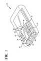
- FIG. 1illustrates a perspective view of a wireless communication device utilizing an antenna assembly according to the present invention
- FIG. 2bottom plan view of the antenna assembly of FIG. 1;
- FIG. 3is a top plan view of the antenna assembly of FIG. 1;
- FIG. 4is a side elevational view of the antenna assembly of FIG. 1;
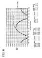
- FIG. 5shows the return loss vs. frequency plot for each antenna of the preferred configuration from FIG. 1;
- FIG. 6shows the free-space azimuth pattern, gain, and front to back ratio of the preferred configuration from FIG. 1 .
- Wireless communication device 10may include a computer, printer device, or other LAN functional devices.
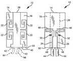
- FIGS. 2-4further illustrate the antenna assembly 12 of FIG. 1 .
- Antenna assembly 12includes a substrate 14 upon which one or more small substantially flat antennas may be positioned.
- the substrateis preferably substantially planar, though alternative configurations may be practicable.
- the substrate 14may be a printed circuit board manufactured of epoxy resin/glass cloth laminate, but other compounds may also be used.
- the substrate 14has a relative dielectric constant of 1-10 with a preferred value of 4.5.
- the substratepreferably has a thickness of between 0.010-0.25 inches.
- the substrate 14defines first and second substantially parallel major surfaces 16 , 18 upon which conductive structures 20 of the antenna assembly 12 are disposed.
- Conductive structures 20including radiator elements 22 , transmission line traces 24 , 26 , reflector element 28 , and impedance matching tabs 30 , 32 , have preferred thickness of 0.001-0.002 inches.
- the conductive structures 20are shown etched upon the substrate 14 , it will be recognized by those skilled in the art that ordinary wire conductors may also be used and disposed on the substrate 14 .
- the conductive structure 20 of the first major surface 16 of the dielectric substrate 14includes a plurality of fed radiating elements 22 in relation to a common reflector element 28 .
- Fed elements 22consist of generally J-shaped traces whose serpentine shape form a radiator as the monopole antenna. Alternative shapes or forms for the radiator segments may be practicable.
- four fed elements 22are defined by serpentine segments and are disposed in symmetric and reflective relation to the common reflector element 28 .
- the four fed elements 22are symmetrically disposed relative to both longitudinal and transverse centerlines of the dielectric substrate 14 .
- the common reflector element 28includes a base portion 40 for coupling the reflector element 28 to the shield conductors 42 of the coax feedlines 44 , as will be described hereinafter.
- the second major surface 18 of the dielectric substrate 14has conductive structures 20 including two microstrip transmission lines 24 , 26 , impedance matching tabs 30 , 32 , and baluns 46 .
- the microstrip transmisson lines 24 , 26utilize the common reflector element 28 on the reverse major surface 16 as a ground plane.
- the microstrip transmission lines 24 , 26are coupled at a first end to a pair of center conductors 48 of the coax feedlines 44 at a substrate edge 50 , and at a second end to the pair of balun structures 46 .
- Baluns 46 or matching networksare configured as serpentine conductive traces and provide a means for coupling rf power to the driven radiator elements 22 .
- the baluns 46are symmetrically disposed relative to a longitudinal center line of the dielectric substrate 14 .
- Conductive structures 20 of the second major surface 18further include a pair of impedance matching tabs 30 , 32 , each associated with a transmission line 24 , 26 and a balun 46 .
- a pair of 50 ohm coax signal lines 44 from the wireless communications device 10may be coupled between the conductive structures 20 of the first and second major surfaces 16 , 18 of the dielectric substrate 14 .
- the edge 50 of the substrate 14may be contiguous with a portion of the printed circuit substrate of a communications device 10 , and microstrip lines 24 , 26 may be connected to corresponding microstrip lines of the device 10 which corresponds to VSWR of less than 1.5:1.
- markers 1 & 2are at frequencies 2.40 and 2.45 GHz., respectively.
- Minimum return loss at the feed locationsis seen to be 17 dB, assuring efficient power transfer.
- the peak gain over the frequency range 2.4-2.45 GHzis +5 dBi, and the front-to-back ration is 7.5 dB.
Landscapes
- Engineering & Computer Science (AREA)
- Computer Networks & Wireless Communication (AREA)
- Variable-Direction Aerials And Aerial Arrays (AREA)
Abstract
Description
Claims (17)
Priority Applications (1)
| Application Number | Priority Date | Filing Date | Title |
|---|---|---|---|
| US09/637,301US6339404B1 (en) | 1999-08-13 | 2000-08-11 | Diversity antenna system for lan communication system |
Applications Claiming Priority (2)
| Application Number | Priority Date | Filing Date | Title |
|---|---|---|---|
| US14890999P | 1999-08-13 | 1999-08-13 | |
| US09/637,301US6339404B1 (en) | 1999-08-13 | 2000-08-11 | Diversity antenna system for lan communication system |
Publications (1)
| Publication Number | Publication Date |
|---|---|
| US6339404B1true US6339404B1 (en) | 2002-01-15 |
Family
ID=22527981
Family Applications (1)
| Application Number | Title | Priority Date | Filing Date |
|---|---|---|---|
| US09/637,301Expired - LifetimeUS6339404B1 (en) | 1999-08-13 | 2000-08-11 | Diversity antenna system for lan communication system |
Country Status (2)
| Country | Link |
|---|---|
| US (1) | US6339404B1 (en) |
| WO (1) | WO2001013461A1 (en) |
Cited By (73)
| Publication number | Priority date | Publication date | Assignee | Title |
|---|---|---|---|---|
| US6542122B1 (en)* | 2001-10-16 | 2003-04-01 | Telefonaktiebolaget Lm Ericsson (Publ) | Patch antenna precision connection |
| WO2003103087A3 (en)* | 2002-06-04 | 2004-03-18 | Skycross Inc | Wideband printed monopole antenna |
| US20040053575A1 (en)* | 2000-10-25 | 2004-03-18 | Rainer Eckert | Portable electronic device |
| KR100444218B1 (en)* | 2001-09-25 | 2004-08-16 | 삼성전기주식회사 | Dual feeding chip antenna for providing diversity |
| US20040183727A1 (en)* | 2003-03-14 | 2004-09-23 | Sunwoo Communication Co., Ltd. | Dual-band omnidirectional antenna for wireless local area network |
| US6819295B1 (en)* | 2003-02-13 | 2004-11-16 | Sheng Yeng Peng | Dual frequency anti-jamming antenna |
| US6828939B2 (en)* | 2002-10-16 | 2004-12-07 | Ain Comm.Technology Co., Ltd. | Multi-band antenna |
| US20050104788A1 (en)* | 2003-11-18 | 2005-05-19 | Chen-Ta Hung | Bracket-antenna assembly and manufacturing method of the same |
| US20050110698A1 (en)* | 2003-11-24 | 2005-05-26 | Sandbridge Technologies Inc. | Modified printed dipole antennas for wireless multi-band communication systems |
| US20050140553A1 (en)* | 2003-12-26 | 2005-06-30 | Nec Corporation | Flat wideband antenna |
| US20050156794A1 (en)* | 2004-01-20 | 2005-07-21 | Theobold David M. | Configurable antenna for a wireless access point |
| US20050219124A1 (en)* | 2002-06-15 | 2005-10-06 | Koninklijke Philips Electronics N.V. | Miniaturized multiband antenna |
| KR100533624B1 (en)* | 2002-04-16 | 2005-12-06 | 삼성전기주식회사 | Multi band chip antenna with dual feeding port, and mobile communication apparatus using the same |
| JP2005347958A (en)* | 2004-06-01 | 2005-12-15 | Toshiba Corp | Antenna device |
| US20060033666A1 (en)* | 2004-08-10 | 2006-02-16 | Hon Hai Precision Ind. Co., Ltd. | Antenna assembly having parasitic element for encreasing antenna gain |
| US20060038738A1 (en)* | 2004-08-18 | 2006-02-23 | Video54 Technologies, Inc. | Wireless system having multiple antennas and multiple radios |
| US20060040707A1 (en)* | 2004-08-18 | 2006-02-23 | Video54 Technologies, Inc. | System and method for transmission parameter control for an antenna apparatus with selectable elements |
| US20060038734A1 (en)* | 2004-08-18 | 2006-02-23 | Video54 Technologies, Inc. | System and method for an omnidirectional planar antenna apparatus with selectable elements |
| US20060038735A1 (en)* | 2004-08-18 | 2006-02-23 | Victor Shtrom | System and method for a minimized antenna apparatus with selectable elements |
| US20060098613A1 (en)* | 2004-11-05 | 2006-05-11 | Video54 Technologies, Inc. | Systems and methods for improved data throughput in communications networks |
| US20060098616A1 (en)* | 2004-11-05 | 2006-05-11 | Ruckus Wireless, Inc. | Throughput enhancement by acknowledgement suppression |
| US20060109067A1 (en)* | 2004-11-22 | 2006-05-25 | Ruckus Wireless, Inc. | Circuit board having a pereipheral antenna apparatus with selectable antenna elements and selectable phase shifting |
| US20060109191A1 (en)* | 2004-11-22 | 2006-05-25 | Video54 Technologies, Inc. | Circuit board having a peripheral antenna apparatus with selectable antenna elements |
| US20060170610A1 (en)* | 2005-01-28 | 2006-08-03 | Tenatronics Limited | Antenna system for remote control automotive application |
| US20060192720A1 (en)* | 2004-08-18 | 2006-08-31 | Ruckus Wireless, Inc. | Multiband omnidirectional planar antenna apparatus with selectable elements |
| US20070018902A1 (en)* | 2005-07-22 | 2007-01-25 | Wistron Neweb Corp. | Electronic device and antenna structure thereof |
| US20070026807A1 (en)* | 2005-07-26 | 2007-02-01 | Ruckus Wireless, Inc. | Coverage enhancement using dynamic antennas |
| US20070115180A1 (en)* | 2004-08-18 | 2007-05-24 | William Kish | Transmission and reception parameter control |
| US20070249324A1 (en)* | 2006-04-24 | 2007-10-25 | Tyan-Shu Jou | Dynamic authentication in secured wireless networks |
| US20070247255A1 (en)* | 2004-08-18 | 2007-10-25 | Victor Shtrom | Reducing stray capacitance in antenna element switching |
| US20070252666A1 (en)* | 2006-04-28 | 2007-11-01 | Ruckus Wireless, Inc. | PIN diode network for multiband RF coupling |
| US20070287450A1 (en)* | 2006-04-24 | 2007-12-13 | Bo-Chieh Yang | Provisioned configuration for automatic wireless connection |
| US20070293178A1 (en)* | 2006-05-23 | 2007-12-20 | Darin Milton | Antenna Control |
| US20080070509A1 (en)* | 2006-08-18 | 2008-03-20 | Kish William S | Closed-Loop Automatic Channel Selection |
| US7358912B1 (en) | 2005-06-24 | 2008-04-15 | Ruckus Wireless, Inc. | Coverage antenna apparatus with selectable horizontal and vertical polarization elements |
| US20080129640A1 (en)* | 2004-08-18 | 2008-06-05 | Ruckus Wireless, Inc. | Antennas with polarization diversity |
| US20080139136A1 (en)* | 2005-06-24 | 2008-06-12 | Victor Shtrom | Multiple-Input Multiple-Output Wireless Antennas |
| US20080204331A1 (en)* | 2007-01-08 | 2008-08-28 | Victor Shtrom | Pattern Shaping of RF Emission Patterns |
| US20090028095A1 (en)* | 2007-07-28 | 2009-01-29 | Kish William S | Wireless Network Throughput Enhancement Through Channel Aware Scheduling |
| US20090079647A1 (en)* | 2007-09-21 | 2009-03-26 | Samsung Electronics Co., Ltd | Multiple Frequency Band Antenna and Antenna system Using the Same |
| US20090124215A1 (en)* | 2007-09-04 | 2009-05-14 | Sierra Wireless, Inc. | Antenna Configurations for Compact Device Wireless Communication |
| US20090122847A1 (en)* | 2007-09-04 | 2009-05-14 | Sierra Wireless, Inc. | Antenna Configurations for Compact Device Wireless Communication |
| USD594447S1 (en)* | 2008-08-11 | 2009-06-16 | Murata Manufacturing Co., Ltd. | Antenna for wireless tag |
| USD594446S1 (en)* | 2008-08-11 | 2009-06-16 | Murata Manufacturing Co., Ltd. | Antenna for wireless tag |
| USD594445S1 (en)* | 2008-08-11 | 2009-06-16 | Murata Manufacturing Co., Ltd. | Antenna for wireless tag |
| US20090180396A1 (en)* | 2008-01-11 | 2009-07-16 | Kish William S | Determining associations in a mesh network |
| US20100053010A1 (en)* | 2004-08-18 | 2010-03-04 | Victor Shtrom | Antennas with Polarization Diversity |
| US20100103066A1 (en)* | 2004-08-18 | 2010-04-29 | Victor Shtrom | Dual Band Dual Polarization Antenna Array |
| US20100103065A1 (en)* | 2004-08-18 | 2010-04-29 | Victor Shtrom | Dual Polarization Antenna with Increased Wireless Coverage |
| US20100231473A1 (en)* | 2009-03-13 | 2010-09-16 | Victor Shtrom | Adjustment of Radiation Patterns Utilizing a Position Sensor |
| US20100259451A1 (en)* | 2009-04-10 | 2010-10-14 | Advanced Connectek Inc. | Digital Television Antenna |
| US20100289705A1 (en)* | 2009-05-12 | 2010-11-18 | Victor Shtrom | Mountable Antenna Elements for Dual Band Antenna |
| US20110096712A1 (en)* | 2004-11-05 | 2011-04-28 | William Kish | Unicast to Multicast Conversion |
| US20110119401A1 (en)* | 2009-11-16 | 2011-05-19 | Kish William S | Determining Role Assignment in a Hybrid Mesh Network |
| US8009644B2 (en) | 2005-12-01 | 2011-08-30 | Ruckus Wireless, Inc. | On-demand services by wireless base station virtualization |
| US20110216685A1 (en)* | 2004-11-05 | 2011-09-08 | Kish William S | Mac based mapping in ip based communications |
| US8049671B2 (en)* | 2007-09-04 | 2011-11-01 | Sierra Wireless, Inc. | Antenna configurations for compact device wireless communication |
| US8059046B2 (en) | 2007-09-04 | 2011-11-15 | Sierra Wireless, Inc. | Antenna configurations for compact device wireless communication |
| US20130210368A1 (en)* | 2012-02-10 | 2013-08-15 | Ralink Technology Corp. | Method and Wireless Communication Device for Antenna Deployment Determination |
| US20140055319A1 (en)* | 2011-01-04 | 2014-02-27 | Industry-Academic Cooperation Foundation Incheon National University | Mimo antenna with no phase change |
| US8756668B2 (en) | 2012-02-09 | 2014-06-17 | Ruckus Wireless, Inc. | Dynamic PSK for hotspots |
| US9092610B2 (en) | 2012-04-04 | 2015-07-28 | Ruckus Wireless, Inc. | Key assignment for a brand |
| US9287633B2 (en) | 2012-08-30 | 2016-03-15 | Industrial Technology Research Institute | Dual frequency coupling feed antenna and adjustable wave beam module using the antenna |
| US9407012B2 (en) | 2010-09-21 | 2016-08-02 | Ruckus Wireless, Inc. | Antenna with dual polarization and mountable antenna elements |
| CN106299596A (en)* | 2016-09-20 | 2017-01-04 | 深圳市中天迅通信技术有限公司 | A kind of POS Serpentis type antenna without frequency deviation |
| US9570799B2 (en) | 2012-09-07 | 2017-02-14 | Ruckus Wireless, Inc. | Multiband monopole antenna apparatus with ground plane aperture |
| US9634403B2 (en) | 2012-02-14 | 2017-04-25 | Ruckus Wireless, Inc. | Radio frequency emission pattern shaping |
| US9769655B2 (en) | 2006-04-24 | 2017-09-19 | Ruckus Wireless, Inc. | Sharing security keys with headless devices |
| US9792188B2 (en) | 2011-05-01 | 2017-10-17 | Ruckus Wireless, Inc. | Remote cable access point reset |
| US9979626B2 (en) | 2009-11-16 | 2018-05-22 | Ruckus Wireless, Inc. | Establishing a mesh network with wired and wireless links |
| US10186750B2 (en) | 2012-02-14 | 2019-01-22 | Arris Enterprises Llc | Radio frequency antenna array with spacing element |
| US10230161B2 (en) | 2013-03-15 | 2019-03-12 | Arris Enterprises Llc | Low-band reflector for dual band directional antenna |
| US20220344804A1 (en)* | 2021-04-22 | 2022-10-27 | Pegatron Corporation | Antenna module |
Families Citing this family (5)
| Publication number | Priority date | Publication date | Assignee | Title |
|---|---|---|---|---|
| US6767360B1 (en) | 2001-02-08 | 2004-07-27 | Inflow Dynamics Inc. | Vascular stent with composite structure for magnetic reasonance imaging capabilities |
| US6781544B2 (en)* | 2002-03-04 | 2004-08-24 | Cisco Technology, Inc. | Diversity antenna for UNII access point |
| US7109923B2 (en)* | 2004-02-23 | 2006-09-19 | Nokia Corporation | Diversity antenna arrangement |
| CN101872892B (en)* | 2009-04-24 | 2014-07-09 | 连展科技电子(昆山)有限公司 | Digital television antenna |
| CN102110877A (en)* | 2010-12-31 | 2011-06-29 | 苏州佳世达电通有限公司 | Planar antenna structure and communication terminal using same |
Citations (20)
| Publication number | Priority date | Publication date | Assignee | Title |
|---|---|---|---|---|
| US4138684A (en) | 1977-05-12 | 1979-02-06 | The United States Of America As Represented By The Secretary Of The Army | Loaded microstrip antenna with integral transformer |
| US4356492A (en) | 1981-01-26 | 1982-10-26 | The United States Of America As Represented By The Secretary Of The Navy | Multi-band single-feed microstrip antenna system |
| US5386215A (en) | 1992-11-20 | 1995-01-31 | Massachusetts Institute Of Technology | Highly efficient planar antenna on a periodic dielectric structure |
| US5557293A (en) | 1995-01-26 | 1996-09-17 | Motorola, Inc. | Multi-loop antenna |
| WO1996037922A1 (en) | 1995-05-24 | 1996-11-28 | Allgon Ab | Device for adjusting the beam direction of an antenna, and feed line structure therefor |
| US5625371A (en) | 1996-02-16 | 1997-04-29 | R.A. Miller Industries, Inc. | Flat plate TV antenna |
| US5657028A (en) | 1995-03-31 | 1997-08-12 | Nokia Moblie Phones Ltd. | Small double C-patch antenna contained in a standard PC card |
| US5680438A (en) | 1992-08-18 | 1997-10-21 | At & T Wireless Communications Products, Ltd. | Telecommunications system having single base unit and plural individual antennas each for communication with one or more remote handsets for use within premises |
| US5680144A (en) | 1996-03-13 | 1997-10-21 | Nokia Mobile Phones Limited | Wideband, stacked double C-patch antenna having gap-coupled parasitic elements |
| US5742258A (en) | 1995-08-22 | 1998-04-21 | Hazeltine Corporation | Low intermodulation electromagnetic feed cellular antennas |
| US5754145A (en) | 1995-08-23 | 1998-05-19 | U.S. Philips Corporation | Printed antenna |
| US5757333A (en) | 1994-07-09 | 1998-05-26 | Northern Telecom Limited | Communications antenna structure |
| US5767812A (en) | 1996-06-17 | 1998-06-16 | Arinc, Inc. | High efficiency, broadband, trapped antenna system |
| WO1998034295A1 (en) | 1997-02-05 | 1998-08-06 | Allgon Ab | Antenna operating with two isolated channels |
| WO1999003168A1 (en) | 1997-07-09 | 1999-01-21 | Allgon Ab | Trap microstrip pifa |
| US5867130A (en) | 1997-03-06 | 1999-02-02 | Motorola, Inc. | Directional center-fed wave dipole antenna |
| WO1999005754A1 (en) | 1997-07-23 | 1999-02-04 | Allgon Ab | Antenna device with improved channel isolation |
| WO1999031757A1 (en) | 1997-12-12 | 1999-06-24 | Allgon Ab | Dual band antenna |
| US5933115A (en) | 1997-06-06 | 1999-08-03 | Motorola, Inc. | Planar antenna with patch radiators for wide bandwidth |
| US6031503A (en) | 1997-02-20 | 2000-02-29 | Raytheon Company | Polarization diverse antenna for portable communication devices |
Family Cites Families (3)
| Publication number | Priority date | Publication date | Assignee | Title |
|---|---|---|---|---|
| US5583510A (en)* | 1994-11-16 | 1996-12-10 | International Business Machines Corporation | Planar antenna in the ISM band with an omnidirectional pattern in the horizontal plane |
| JP3761988B2 (en)* | 1996-09-18 | 2006-03-29 | 本田技研工業株式会社 | Antenna device |
| CA2241128A1 (en)* | 1997-06-30 | 1998-12-30 | Sony International (Europe) Gmbh | Wide band printed phase array antenna for microwave and mm-wave applications |
- 2000
- 2000-08-11USUS09/637,301patent/US6339404B1/ennot_activeExpired - Lifetime
- 2000-08-11WOPCT/US2000/022256patent/WO2001013461A1/enactiveApplication Filing
Patent Citations (20)
| Publication number | Priority date | Publication date | Assignee | Title |
|---|---|---|---|---|
| US4138684A (en) | 1977-05-12 | 1979-02-06 | The United States Of America As Represented By The Secretary Of The Army | Loaded microstrip antenna with integral transformer |
| US4356492A (en) | 1981-01-26 | 1982-10-26 | The United States Of America As Represented By The Secretary Of The Navy | Multi-band single-feed microstrip antenna system |
| US5680438A (en) | 1992-08-18 | 1997-10-21 | At & T Wireless Communications Products, Ltd. | Telecommunications system having single base unit and plural individual antennas each for communication with one or more remote handsets for use within premises |
| US5386215A (en) | 1992-11-20 | 1995-01-31 | Massachusetts Institute Of Technology | Highly efficient planar antenna on a periodic dielectric structure |
| US5757333A (en) | 1994-07-09 | 1998-05-26 | Northern Telecom Limited | Communications antenna structure |
| US5557293A (en) | 1995-01-26 | 1996-09-17 | Motorola, Inc. | Multi-loop antenna |
| US5657028A (en) | 1995-03-31 | 1997-08-12 | Nokia Moblie Phones Ltd. | Small double C-patch antenna contained in a standard PC card |
| WO1996037922A1 (en) | 1995-05-24 | 1996-11-28 | Allgon Ab | Device for adjusting the beam direction of an antenna, and feed line structure therefor |
| US5742258A (en) | 1995-08-22 | 1998-04-21 | Hazeltine Corporation | Low intermodulation electromagnetic feed cellular antennas |
| US5754145A (en) | 1995-08-23 | 1998-05-19 | U.S. Philips Corporation | Printed antenna |
| US5625371A (en) | 1996-02-16 | 1997-04-29 | R.A. Miller Industries, Inc. | Flat plate TV antenna |
| US5680144A (en) | 1996-03-13 | 1997-10-21 | Nokia Mobile Phones Limited | Wideband, stacked double C-patch antenna having gap-coupled parasitic elements |
| US5767812A (en) | 1996-06-17 | 1998-06-16 | Arinc, Inc. | High efficiency, broadband, trapped antenna system |
| WO1998034295A1 (en) | 1997-02-05 | 1998-08-06 | Allgon Ab | Antenna operating with two isolated channels |
| US6031503A (en) | 1997-02-20 | 2000-02-29 | Raytheon Company | Polarization diverse antenna for portable communication devices |
| US5867130A (en) | 1997-03-06 | 1999-02-02 | Motorola, Inc. | Directional center-fed wave dipole antenna |
| US5933115A (en) | 1997-06-06 | 1999-08-03 | Motorola, Inc. | Planar antenna with patch radiators for wide bandwidth |
| WO1999003168A1 (en) | 1997-07-09 | 1999-01-21 | Allgon Ab | Trap microstrip pifa |
| WO1999005754A1 (en) | 1997-07-23 | 1999-02-04 | Allgon Ab | Antenna device with improved channel isolation |
| WO1999031757A1 (en) | 1997-12-12 | 1999-06-24 | Allgon Ab | Dual band antenna |
Cited By (191)
| Publication number | Priority date | Publication date | Assignee | Title |
|---|---|---|---|---|
| US20040053575A1 (en)* | 2000-10-25 | 2004-03-18 | Rainer Eckert | Portable electronic device |
| KR100444218B1 (en)* | 2001-09-25 | 2004-08-16 | 삼성전기주식회사 | Dual feeding chip antenna for providing diversity |
| US6542122B1 (en)* | 2001-10-16 | 2003-04-01 | Telefonaktiebolaget Lm Ericsson (Publ) | Patch antenna precision connection |
| US20030071756A1 (en)* | 2001-10-16 | 2003-04-17 | Thomas Bolin | Patch antenna precision connection |
| KR100533624B1 (en)* | 2002-04-16 | 2005-12-06 | 삼성전기주식회사 | Multi band chip antenna with dual feeding port, and mobile communication apparatus using the same |
| WO2003103087A3 (en)* | 2002-06-04 | 2004-03-18 | Skycross Inc | Wideband printed monopole antenna |
| US20040125020A1 (en)* | 2002-06-04 | 2004-07-01 | Hendler Jason M. | Wideband printed monopole antenna |
| US6937193B2 (en) | 2002-06-04 | 2005-08-30 | Skycross, Inc. | Wideband printed monopole antenna |
| US20050219124A1 (en)* | 2002-06-15 | 2005-10-06 | Koninklijke Philips Electronics N.V. | Miniaturized multiband antenna |
| US6828939B2 (en)* | 2002-10-16 | 2004-12-07 | Ain Comm.Technology Co., Ltd. | Multi-band antenna |
| US6819295B1 (en)* | 2003-02-13 | 2004-11-16 | Sheng Yeng Peng | Dual frequency anti-jamming antenna |
| US6859176B2 (en) | 2003-03-14 | 2005-02-22 | Sunwoo Communication Co., Ltd. | Dual-band omnidirectional antenna for wireless local area network |
| US20040183727A1 (en)* | 2003-03-14 | 2004-09-23 | Sunwoo Communication Co., Ltd. | Dual-band omnidirectional antenna for wireless local area network |
| US20050104788A1 (en)* | 2003-11-18 | 2005-05-19 | Chen-Ta Hung | Bracket-antenna assembly and manufacturing method of the same |
| US7242353B2 (en) | 2003-11-18 | 2007-07-10 | Hon Hai Precision Ind. Co., Ltd. | Bracket-antenna assembly and manufacturing method of the same |
| US20050110698A1 (en)* | 2003-11-24 | 2005-05-26 | Sandbridge Technologies Inc. | Modified printed dipole antennas for wireless multi-band communication systems |
| US20060208956A1 (en)* | 2003-11-24 | 2006-09-21 | Emanoil Surducan | Modified printed dipole antennas for wireless multi-band communication systems |
| US7095382B2 (en)* | 2003-11-24 | 2006-08-22 | Sandbridge Technologies, Inc. | Modified printed dipole antennas for wireless multi-band communications systems |
| CN100454662C (en)* | 2003-12-26 | 2009-01-21 | 日本电气株式会社 | Flat wideband antenna |
| AU2004244650B2 (en)* | 2003-12-26 | 2009-01-08 | Nec Corporation | Flat wideband antenna |
| EP1548878A3 (en)* | 2003-12-26 | 2005-07-06 | Nec Corporation | Flat wideband antenna |
| US20050140553A1 (en)* | 2003-12-26 | 2005-06-30 | Nec Corporation | Flat wideband antenna |
| US7106258B2 (en) | 2003-12-26 | 2006-09-12 | Nec Corporation | Flat wideband antenna |
| US20050156794A1 (en)* | 2004-01-20 | 2005-07-21 | Theobold David M. | Configurable antenna for a wireless access point |
| US7119744B2 (en)* | 2004-01-20 | 2006-10-10 | Cisco Technology, Inc. | Configurable antenna for a wireless access point |
| JP2005347958A (en)* | 2004-06-01 | 2005-12-15 | Toshiba Corp | Antenna device |
| US20060033666A1 (en)* | 2004-08-10 | 2006-02-16 | Hon Hai Precision Ind. Co., Ltd. | Antenna assembly having parasitic element for encreasing antenna gain |
| CN1734836B (en)* | 2004-08-10 | 2010-11-17 | 富士康(昆山)电脑接插件有限公司 | Antenna |
| US7151500B2 (en) | 2004-08-10 | 2006-12-19 | Hon Hai Precision Ind. Co., Ltd. | Antenna assembly having parasitic element for increasing antenna gain |
| US20060192720A1 (en)* | 2004-08-18 | 2006-08-31 | Ruckus Wireless, Inc. | Multiband omnidirectional planar antenna apparatus with selectable elements |
| US7899497B2 (en) | 2004-08-18 | 2011-03-01 | Ruckus Wireless, Inc. | System and method for transmission parameter control for an antenna apparatus with selectable elements |
| US8594734B2 (en) | 2004-08-18 | 2013-11-26 | Ruckus Wireless, Inc. | Transmission and reception parameter control |
| US8583183B2 (en) | 2004-08-18 | 2013-11-12 | Ruckus Wireless, Inc. | Transmission and reception parameter control |
| US8314749B2 (en) | 2004-08-18 | 2012-11-20 | Ruckus Wireless, Inc. | Dual band dual polarization antenna array |
| US8031129B2 (en) | 2004-08-18 | 2011-10-04 | Ruckus Wireless, Inc. | Dual band dual polarization antenna array |
| US20110205137A1 (en)* | 2004-08-18 | 2011-08-25 | Victor Shtrom | Antenna with Polarization Diversity |
| US7965252B2 (en) | 2004-08-18 | 2011-06-21 | Ruckus Wireless, Inc. | Dual polarization antenna array with increased wireless coverage |
| US20110095960A1 (en)* | 2004-08-18 | 2011-04-28 | Victor Shtrom | Antenna with selectable elements for use in wireless communications |
| US7933628B2 (en) | 2004-08-18 | 2011-04-26 | Ruckus Wireless, Inc. | Transmission and reception parameter control |
| US20070115180A1 (en)* | 2004-08-18 | 2007-05-24 | William Kish | Transmission and reception parameter control |
| US8860629B2 (en) | 2004-08-18 | 2014-10-14 | Ruckus Wireless, Inc. | Dual band dual polarization antenna array |
| WO2006023247A1 (en)* | 2004-08-18 | 2006-03-02 | Ruckus Wireless, Inc. | System and method for an omnidirectional planar antenna apparatus with selectable elements |
| US7880683B2 (en) | 2004-08-18 | 2011-02-01 | Ruckus Wireless, Inc. | Antennas with polarization diversity |
| US10187307B2 (en) | 2004-08-18 | 2019-01-22 | Arris Enterprises Llc | Transmission and reception parameter control |
| US20070247255A1 (en)* | 2004-08-18 | 2007-10-25 | Victor Shtrom | Reducing stray capacitance in antenna element switching |
| US10181655B2 (en) | 2004-08-18 | 2019-01-15 | Arris Enterprises Llc | Antenna with polarization diversity |
| US7292198B2 (en)* | 2004-08-18 | 2007-11-06 | Ruckus Wireless, Inc. | System and method for an omnidirectional planar antenna apparatus with selectable elements |
| US20060038735A1 (en)* | 2004-08-18 | 2006-02-23 | Victor Shtrom | System and method for a minimized antenna apparatus with selectable elements |
| US7877113B2 (en) | 2004-08-18 | 2011-01-25 | Ruckus Wireless, Inc. | Transmission parameter control for an antenna apparatus with selectable elements |
| US9837711B2 (en) | 2004-08-18 | 2017-12-05 | Ruckus Wireless, Inc. | Antenna with selectable elements for use in wireless communications |
| US20060038738A1 (en)* | 2004-08-18 | 2006-02-23 | Video54 Technologies, Inc. | Wireless system having multiple antennas and multiple radios |
| US7362280B2 (en) | 2004-08-18 | 2008-04-22 | Ruckus Wireless, Inc. | System and method for a minimized antenna apparatus with selectable elements |
| US20080129640A1 (en)* | 2004-08-18 | 2008-06-05 | Ruckus Wireless, Inc. | Antennas with polarization diversity |
| US20080136725A1 (en)* | 2004-08-18 | 2008-06-12 | Victor Shtrom | Minimized Antenna Apparatus with Selectable Elements |
| US9019165B2 (en) | 2004-08-18 | 2015-04-28 | Ruckus Wireless, Inc. | Antenna with selectable elements for use in wireless communications |
| US20080136715A1 (en)* | 2004-08-18 | 2008-06-12 | Victor Shtrom | Antenna with Selectable Elements for Use in Wireless Communications |
| US20100103065A1 (en)* | 2004-08-18 | 2010-04-29 | Victor Shtrom | Dual Polarization Antenna with Increased Wireless Coverage |
| US20100103066A1 (en)* | 2004-08-18 | 2010-04-29 | Victor Shtrom | Dual Band Dual Polarization Antenna Array |
| US20100091749A1 (en)* | 2004-08-18 | 2010-04-15 | William Kish | Transmission and Reception Parameter Control |
| US7696946B2 (en) | 2004-08-18 | 2010-04-13 | Ruckus Wireless, Inc. | Reducing stray capacitance in antenna element switching |
| US20060038734A1 (en)* | 2004-08-18 | 2006-02-23 | Video54 Technologies, Inc. | System and method for an omnidirectional planar antenna apparatus with selectable elements |
| US20060040707A1 (en)* | 2004-08-18 | 2006-02-23 | Video54 Technologies, Inc. | System and method for transmission parameter control for an antenna apparatus with selectable elements |
| US20090022066A1 (en)* | 2004-08-18 | 2009-01-22 | Kish William S | Transmission parameter control for an antenna apparatus with selectable elements |
| US20100053010A1 (en)* | 2004-08-18 | 2010-03-04 | Victor Shtrom | Antennas with Polarization Diversity |
| US9077071B2 (en) | 2004-08-18 | 2015-07-07 | Ruckus Wireless, Inc. | Antenna with polarization diversity |
| US7498996B2 (en) | 2004-08-18 | 2009-03-03 | Ruckus Wireless, Inc. | Antennas with polarization diversity |
| US7652632B2 (en)* | 2004-08-18 | 2010-01-26 | Ruckus Wireless, Inc. | Multiband omnidirectional planar antenna apparatus with selectable elements |
| US20090310590A1 (en)* | 2004-08-18 | 2009-12-17 | William Kish | Transmission and Reception Parameter Control |
| US9153876B2 (en) | 2004-08-18 | 2015-10-06 | Ruckus Wireless, Inc. | Transmission and reception parameter control |
| US7511680B2 (en) | 2004-08-18 | 2009-03-31 | Ruckus Wireless, Inc. | Minimized antenna apparatus with selectable elements |
| US9484638B2 (en) | 2004-08-18 | 2016-11-01 | Ruckus Wireless, Inc. | Transmission and reception parameter control |
| US20080137681A1 (en)* | 2004-11-05 | 2008-06-12 | Kish William S | Communications throughput with unicast packet transmission alternative |
| US8619662B2 (en) | 2004-11-05 | 2013-12-31 | Ruckus Wireless, Inc. | Unicast to multicast conversion |
| US8634402B2 (en) | 2004-11-05 | 2014-01-21 | Ruckus Wireless, Inc. | Distributed access point for IP based communications |
| US8638708B2 (en) | 2004-11-05 | 2014-01-28 | Ruckus Wireless, Inc. | MAC based mapping in IP based communications |
| US8125975B2 (en) | 2004-11-05 | 2012-02-28 | Ruckus Wireless, Inc. | Communications throughput with unicast packet transmission alternative |
| US9240868B2 (en) | 2004-11-05 | 2016-01-19 | Ruckus Wireless, Inc. | Increasing reliable data throughput in a wireless network |
| US8089949B2 (en) | 2004-11-05 | 2012-01-03 | Ruckus Wireless, Inc. | Distributed access point for IP based communications |
| US8824357B2 (en) | 2004-11-05 | 2014-09-02 | Ruckus Wireless, Inc. | Throughput enhancement by acknowledgment suppression |
| US20060098616A1 (en)* | 2004-11-05 | 2006-05-11 | Ruckus Wireless, Inc. | Throughput enhancement by acknowledgement suppression |
| US20110216685A1 (en)* | 2004-11-05 | 2011-09-08 | Kish William S | Mac based mapping in ip based communications |
| US20060098613A1 (en)* | 2004-11-05 | 2006-05-11 | Video54 Technologies, Inc. | Systems and methods for improved data throughput in communications networks |
| US7505447B2 (en) | 2004-11-05 | 2009-03-17 | Ruckus Wireless, Inc. | Systems and methods for improved data throughput in communications networks |
| US20110096712A1 (en)* | 2004-11-05 | 2011-04-28 | William Kish | Unicast to Multicast Conversion |
| US9019886B2 (en) | 2004-11-05 | 2015-04-28 | Ruckus Wireless, Inc. | Unicast to multicast conversion |
| US9661475B2 (en) | 2004-11-05 | 2017-05-23 | Ruckus Wireless, Inc. | Distributed access point for IP based communications |
| US9066152B2 (en) | 2004-11-05 | 2015-06-23 | Ruckus Wireless, Inc. | Distributed access point for IP based communications |
| US9071942B2 (en) | 2004-11-05 | 2015-06-30 | Ruckus Wireless, Inc. | MAC based mapping in IP based communications |
| US9794758B2 (en) | 2004-11-05 | 2017-10-17 | Ruckus Wireless, Inc. | Increasing reliable data throughput in a wireless network |
| US7787436B2 (en) | 2004-11-05 | 2010-08-31 | Ruckus Wireless, Inc. | Communications throughput with multiple physical data rate transmission determinations |
| US7498999B2 (en) | 2004-11-22 | 2009-03-03 | Ruckus Wireless, Inc. | Circuit board having a peripheral antenna apparatus with selectable antenna elements and selectable phase shifting |
| US7193562B2 (en) | 2004-11-22 | 2007-03-20 | Ruckus Wireless, Inc. | Circuit board having a peripheral antenna apparatus with selectable antenna elements |
| US20060109191A1 (en)* | 2004-11-22 | 2006-05-25 | Video54 Technologies, Inc. | Circuit board having a peripheral antenna apparatus with selectable antenna elements |
| US9379456B2 (en) | 2004-11-22 | 2016-06-28 | Ruckus Wireless, Inc. | Antenna array |
| US20060109067A1 (en)* | 2004-11-22 | 2006-05-25 | Ruckus Wireless, Inc. | Circuit board having a pereipheral antenna apparatus with selectable antenna elements and selectable phase shifting |
| US20100053023A1 (en)* | 2004-11-22 | 2010-03-04 | Victor Shtrom | Antenna Array |
| US20070218953A1 (en)* | 2004-11-22 | 2007-09-20 | Victor Shtrom | Increased wireless coverage patterns |
| US7525486B2 (en) | 2004-11-22 | 2009-04-28 | Ruckus Wireless, Inc. | Increased wireless coverage patterns |
| US9344161B2 (en) | 2004-12-09 | 2016-05-17 | Ruckus Wireless, Inc. | Coverage enhancement using dynamic antennas and virtual access points |
| US9093758B2 (en) | 2004-12-09 | 2015-07-28 | Ruckus Wireless, Inc. | Coverage antenna apparatus with selectable horizontal and vertical polarization elements |
| US20100008343A1 (en)* | 2004-12-09 | 2010-01-14 | William Kish | Coverage Enhancement Using Dynamic Antennas and Virtual Access Points |
| US9270029B2 (en) | 2005-01-21 | 2016-02-23 | Ruckus Wireless, Inc. | Pattern shaping of RF emission patterns |
| US10056693B2 (en) | 2005-01-21 | 2018-08-21 | Ruckus Wireless, Inc. | Pattern shaping of RF emission patterns |
| US20060170610A1 (en)* | 2005-01-28 | 2006-08-03 | Tenatronics Limited | Antenna system for remote control automotive application |
| US9577346B2 (en) | 2005-06-24 | 2017-02-21 | Ruckus Wireless, Inc. | Vertical multiple-input multiple-output wireless antennas |
| US20090075606A1 (en)* | 2005-06-24 | 2009-03-19 | Victor Shtrom | Vertical multiple-input multiple-output wireless antennas |
| US7358912B1 (en) | 2005-06-24 | 2008-04-15 | Ruckus Wireless, Inc. | Coverage antenna apparatus with selectable horizontal and vertical polarization elements |
| US7675474B2 (en) | 2005-06-24 | 2010-03-09 | Ruckus Wireless, Inc. | Horizontal multiple-input multiple-output wireless antennas |
| US20080291098A1 (en)* | 2005-06-24 | 2008-11-27 | William Kish | Coverage antenna apparatus with selectable horizontal and vertical polarization elements |
| US7646343B2 (en) | 2005-06-24 | 2010-01-12 | Ruckus Wireless, Inc. | Multiple-input multiple-output wireless antennas |
| US8704720B2 (en) | 2005-06-24 | 2014-04-22 | Ruckus Wireless, Inc. | Coverage antenna apparatus with selectable horizontal and vertical polarization elements |
| US8836606B2 (en) | 2005-06-24 | 2014-09-16 | Ruckus Wireless, Inc. | Coverage antenna apparatus with selectable horizontal and vertical polarization elements |
| US20080204349A1 (en)* | 2005-06-24 | 2008-08-28 | Victor Shtrom | Horizontal multiple-input multiple-output wireless antennas |
| US8068068B2 (en) | 2005-06-24 | 2011-11-29 | Ruckus Wireless, Inc. | Coverage antenna apparatus with selectable horizontal and vertical polarization elements |
| US20080139136A1 (en)* | 2005-06-24 | 2008-06-12 | Victor Shtrom | Multiple-Input Multiple-Output Wireless Antennas |
| US7224315B2 (en) | 2005-07-22 | 2007-05-29 | Wistron Neweb Corp. | Electronic device and antenna structure thereof |
| US20070018902A1 (en)* | 2005-07-22 | 2007-01-25 | Wistron Neweb Corp. | Electronic device and antenna structure thereof |
| US8792414B2 (en) | 2005-07-26 | 2014-07-29 | Ruckus Wireless, Inc. | Coverage enhancement using dynamic antennas |
| US20070026807A1 (en)* | 2005-07-26 | 2007-02-01 | Ruckus Wireless, Inc. | Coverage enhancement using dynamic antennas |
| US8923265B2 (en) | 2005-12-01 | 2014-12-30 | Ruckus Wireless, Inc. | On-demand services by wireless base station virtualization |
| US9313798B2 (en) | 2005-12-01 | 2016-04-12 | Ruckus Wireless, Inc. | On-demand services by wireless base station virtualization |
| US8605697B2 (en) | 2005-12-01 | 2013-12-10 | Ruckus Wireless, Inc. | On-demand services by wireless base station virtualization |
| US8009644B2 (en) | 2005-12-01 | 2011-08-30 | Ruckus Wireless, Inc. | On-demand services by wireless base station virtualization |
| US20070287450A1 (en)* | 2006-04-24 | 2007-12-13 | Bo-Chieh Yang | Provisioned configuration for automatic wireless connection |
| US20110055898A1 (en)* | 2006-04-24 | 2011-03-03 | Tyan-Shu Jou | Dynamic Authentication in Secured Wireless Networks |
| US8607315B2 (en) | 2006-04-24 | 2013-12-10 | Ruckus Wireless, Inc. | Dynamic authentication in secured wireless networks |
| US20070249324A1 (en)* | 2006-04-24 | 2007-10-25 | Tyan-Shu Jou | Dynamic authentication in secured wireless networks |
| US9131378B2 (en) | 2006-04-24 | 2015-09-08 | Ruckus Wireless, Inc. | Dynamic authentication in secured wireless networks |
| US8272036B2 (en) | 2006-04-24 | 2012-09-18 | Ruckus Wireless, Inc. | Dynamic authentication in secured wireless networks |
| US9769655B2 (en) | 2006-04-24 | 2017-09-19 | Ruckus Wireless, Inc. | Sharing security keys with headless devices |
| US7788703B2 (en) | 2006-04-24 | 2010-08-31 | Ruckus Wireless, Inc. | Dynamic authentication in secured wireless networks |
| US7669232B2 (en) | 2006-04-24 | 2010-02-23 | Ruckus Wireless, Inc. | Dynamic authentication in secured wireless networks |
| US9071583B2 (en) | 2006-04-24 | 2015-06-30 | Ruckus Wireless, Inc. | Provisioned configuration for automatic wireless connection |
| US20090092255A1 (en)* | 2006-04-24 | 2009-04-09 | Ruckus Wireless, Inc. | Dynamic Authentication in Secured Wireless Networks |
| US7639106B2 (en) | 2006-04-28 | 2009-12-29 | Ruckus Wireless, Inc. | PIN diode network for multiband RF coupling |
| US20070252666A1 (en)* | 2006-04-28 | 2007-11-01 | Ruckus Wireless, Inc. | PIN diode network for multiband RF coupling |
| US20070293178A1 (en)* | 2006-05-23 | 2007-12-20 | Darin Milton | Antenna Control |
| US9780813B2 (en) | 2006-08-18 | 2017-10-03 | Ruckus Wireless, Inc. | Closed-loop automatic channel selection |
| US8670725B2 (en) | 2006-08-18 | 2014-03-11 | Ruckus Wireless, Inc. | Closed-loop automatic channel selection |
| US20080070509A1 (en)* | 2006-08-18 | 2008-03-20 | Kish William S | Closed-Loop Automatic Channel Selection |
| US20080204331A1 (en)* | 2007-01-08 | 2008-08-28 | Victor Shtrom | Pattern Shaping of RF Emission Patterns |
| US7893882B2 (en) | 2007-01-08 | 2011-02-22 | Ruckus Wireless, Inc. | Pattern shaping of RF emission patterns |
| US8686905B2 (en) | 2007-01-08 | 2014-04-01 | Ruckus Wireless, Inc. | Pattern shaping of RF emission patterns |
| US20090028095A1 (en)* | 2007-07-28 | 2009-01-29 | Kish William S | Wireless Network Throughput Enhancement Through Channel Aware Scheduling |
| US9271327B2 (en) | 2007-07-28 | 2016-02-23 | Ruckus Wireless, Inc. | Wireless network throughput enhancement through channel aware scheduling |
| US8547899B2 (en) | 2007-07-28 | 2013-10-01 | Ruckus Wireless, Inc. | Wireless network throughput enhancement through channel aware scheduling |
| US9674862B2 (en) | 2007-07-28 | 2017-06-06 | Ruckus Wireless, Inc. | Wireless network throughput enhancement through channel aware scheduling |
| US8049671B2 (en)* | 2007-09-04 | 2011-11-01 | Sierra Wireless, Inc. | Antenna configurations for compact device wireless communication |
| US8059046B2 (en) | 2007-09-04 | 2011-11-15 | Sierra Wireless, Inc. | Antenna configurations for compact device wireless communication |
| US20090124215A1 (en)* | 2007-09-04 | 2009-05-14 | Sierra Wireless, Inc. | Antenna Configurations for Compact Device Wireless Communication |
| US20090122847A1 (en)* | 2007-09-04 | 2009-05-14 | Sierra Wireless, Inc. | Antenna Configurations for Compact Device Wireless Communication |
| US8766870B2 (en)* | 2007-09-21 | 2014-07-01 | Samsung Electronics Co., Ltd. | Multiple frequency band antenna and antenna system using the same |
| US20090079647A1 (en)* | 2007-09-21 | 2009-03-26 | Samsung Electronics Co., Ltd | Multiple Frequency Band Antenna and Antenna system Using the Same |
| US8355343B2 (en) | 2008-01-11 | 2013-01-15 | Ruckus Wireless, Inc. | Determining associations in a mesh network |
| US20090180396A1 (en)* | 2008-01-11 | 2009-07-16 | Kish William S | Determining associations in a mesh network |
| US8780760B2 (en) | 2008-01-11 | 2014-07-15 | Ruckus Wireless, Inc. | Determining associations in a mesh network |
| USD594447S1 (en)* | 2008-08-11 | 2009-06-16 | Murata Manufacturing Co., Ltd. | Antenna for wireless tag |
| USD594445S1 (en)* | 2008-08-11 | 2009-06-16 | Murata Manufacturing Co., Ltd. | Antenna for wireless tag |
| USD594446S1 (en)* | 2008-08-11 | 2009-06-16 | Murata Manufacturing Co., Ltd. | Antenna for wireless tag |
| US20100231473A1 (en)* | 2009-03-13 | 2010-09-16 | Victor Shtrom | Adjustment of Radiation Patterns Utilizing a Position Sensor |
| US8217843B2 (en) | 2009-03-13 | 2012-07-10 | Ruckus Wireless, Inc. | Adjustment of radiation patterns utilizing a position sensor |
| US8723741B2 (en) | 2009-03-13 | 2014-05-13 | Ruckus Wireless, Inc. | Adjustment of radiation patterns utilizing a position sensor |
| TWI427858B (en)* | 2009-04-10 | 2014-02-21 | Advanced Connectek Inc | Digital TV antenna |
| US20100259451A1 (en)* | 2009-04-10 | 2010-10-14 | Advanced Connectek Inc. | Digital Television Antenna |
| US20100289705A1 (en)* | 2009-05-12 | 2010-11-18 | Victor Shtrom | Mountable Antenna Elements for Dual Band Antenna |
| US8698675B2 (en) | 2009-05-12 | 2014-04-15 | Ruckus Wireless, Inc. | Mountable antenna elements for dual band antenna |
| US9419344B2 (en) | 2009-05-12 | 2016-08-16 | Ruckus Wireless, Inc. | Mountable antenna elements for dual band antenna |
| US10224621B2 (en) | 2009-05-12 | 2019-03-05 | Arris Enterprises Llc | Mountable antenna elements for dual band antenna |
| US9999087B2 (en) | 2009-11-16 | 2018-06-12 | Ruckus Wireless, Inc. | Determining role assignment in a hybrid mesh network |
| US9979626B2 (en) | 2009-11-16 | 2018-05-22 | Ruckus Wireless, Inc. | Establishing a mesh network with wired and wireless links |
| US20110119401A1 (en)* | 2009-11-16 | 2011-05-19 | Kish William S | Determining Role Assignment in a Hybrid Mesh Network |
| US9407012B2 (en) | 2010-09-21 | 2016-08-02 | Ruckus Wireless, Inc. | Antenna with dual polarization and mountable antenna elements |
| US20140055319A1 (en)* | 2011-01-04 | 2014-02-27 | Industry-Academic Cooperation Foundation Incheon National University | Mimo antenna with no phase change |
| US9768505B2 (en)* | 2011-01-04 | 2017-09-19 | Lg Innotek Co., Ltd. | MIMO antenna with no phase change |
| US9792188B2 (en) | 2011-05-01 | 2017-10-17 | Ruckus Wireless, Inc. | Remote cable access point reset |
| US9596605B2 (en) | 2012-02-09 | 2017-03-14 | Ruckus Wireless, Inc. | Dynamic PSK for hotspots |
| US9226146B2 (en) | 2012-02-09 | 2015-12-29 | Ruckus Wireless, Inc. | Dynamic PSK for hotspots |
| US8756668B2 (en) | 2012-02-09 | 2014-06-17 | Ruckus Wireless, Inc. | Dynamic PSK for hotspots |
| US20130210368A1 (en)* | 2012-02-10 | 2013-08-15 | Ralink Technology Corp. | Method and Wireless Communication Device for Antenna Deployment Determination |
| US9692532B2 (en)* | 2012-02-10 | 2017-06-27 | Mediatek Inc. | Method and wireless communication device for antenna deployment determination |
| US9634403B2 (en) | 2012-02-14 | 2017-04-25 | Ruckus Wireless, Inc. | Radio frequency emission pattern shaping |
| US10186750B2 (en) | 2012-02-14 | 2019-01-22 | Arris Enterprises Llc | Radio frequency antenna array with spacing element |
| US10734737B2 (en) | 2012-02-14 | 2020-08-04 | Arris Enterprises Llc | Radio frequency emission pattern shaping |
| US10182350B2 (en) | 2012-04-04 | 2019-01-15 | Arris Enterprises Llc | Key assignment for a brand |
| US9092610B2 (en) | 2012-04-04 | 2015-07-28 | Ruckus Wireless, Inc. | Key assignment for a brand |
| US9287633B2 (en) | 2012-08-30 | 2016-03-15 | Industrial Technology Research Institute | Dual frequency coupling feed antenna and adjustable wave beam module using the antenna |
| US9570799B2 (en) | 2012-09-07 | 2017-02-14 | Ruckus Wireless, Inc. | Multiband monopole antenna apparatus with ground plane aperture |
| US10230161B2 (en) | 2013-03-15 | 2019-03-12 | Arris Enterprises Llc | Low-band reflector for dual band directional antenna |
| CN106299596A (en)* | 2016-09-20 | 2017-01-04 | 深圳市中天迅通信技术有限公司 | A kind of POS Serpentis type antenna without frequency deviation |
| US20220344804A1 (en)* | 2021-04-22 | 2022-10-27 | Pegatron Corporation | Antenna module |
| US12080943B2 (en)* | 2021-04-22 | 2024-09-03 | Pegatron Corporation | Antenna module |
Also Published As
| Publication number | Publication date |
|---|---|
| WO2001013461A1 (en) | 2001-02-22 |
Similar Documents
| Publication | Publication Date | Title |
|---|---|---|
| US6339404B1 (en) | Diversity antenna system for lan communication system | |
| US11545761B2 (en) | Dual-band cross-polarized 5G mm-wave phased array antenna | |
| US6310584B1 (en) | Low profile high polarization purity dual-polarized antennas | |
| US6337666B1 (en) | Planar sleeve dipole antenna | |
| US5771025A (en) | Folded mono-bow antennas and antenna systems for use in cellular and other wireless communication systems | |
| US5945951A (en) | High isolation dual polarized antenna system with microstrip-fed aperture coupled patches | |
| US6377227B1 (en) | High efficiency feed network for antennas | |
| US5070340A (en) | Broadband microstrip-fed antenna | |
| US6593891B2 (en) | Antenna apparatus having cross-shaped slot | |
| US9935373B2 (en) | Self-grounded antenna arrangement | |
| EP2369680B1 (en) | Multi polarization conformal channel monopole antenna | |
| US5760747A (en) | Energy diversity antenna | |
| US6486836B1 (en) | Handheld wireless communication device having antenna with parasitic element exhibiting multiple polarization | |
| CN101277139A (en) | Broadband beam steering antenna | |
| US8228254B2 (en) | Miniaturized antenna element and array | |
| US6259416B1 (en) | Wideband slot-loop antennas for wireless communication systems | |
| US8416137B2 (en) | Low-profile wide-bandwidth radio frequency antenna | |
| US6879296B2 (en) | Horizontally polarized slot antenna with omni-directional and sectorial radiation patterns | |
| GB2424765A (en) | Dipole antenna with an impedance matching arrangement | |
| US7292201B2 (en) | Directional antenna system with multi-use elements | |
| KR100449857B1 (en) | Wideband Printed Dipole Antenna | |
| WO2023138324A1 (en) | Antenna structure, electronic device and wireless network system | |
| KR20040074257A (en) | Dual-band omnidirectional antennas for wireless LAN | |
| EP1168493B1 (en) | Dual polarisation antennas | |
| CN1156941C (en) | dipole antenna combination |
Legal Events
| Date | Code | Title | Description |
|---|---|---|---|
| AS | Assignment | Owner name:RANGESTAR WIRELESS, INC., CALIFORNIA Free format text:ASSIGNMENT OF ASSIGNORS INTEREST;ASSIGNOR:GREG, JOHNSON;REEL/FRAME:012338/0369 Effective date:20010806 Owner name:RANGESTAR WIRELESS, INC., CALIFORNIA Free format text:ASSIGNMENT OF ASSIGNORS INTEREST;ASSIGNOR:KEILEN, DONALD H.;REEL/FRAME:012341/0299 Effective date:20010814 | |
| FEPP | Fee payment procedure | Free format text:PAT HOLDER CLAIMS SMALL ENTITY STATUS, ENTITY STATUS SET TO SMALL (ORIGINAL EVENT CODE: LTOS); ENTITY STATUS OF PATENT OWNER: LARGE ENTITY | |
| STCF | Information on status: patent grant | Free format text:PATENTED CASE | |
| AS | Assignment | Owner name:TYCO ELECTRONICS LOGISTICS AG, SWITZERLAND Free format text:ASSIGNMENT OF ASSIGNORS INTEREST;ASSIGNOR:RANGESTAR WIRELESS, INC.;REEL/FRAME:012683/0307 Effective date:20010928 | |
| FEPP | Fee payment procedure | Free format text:PAT HOLDER NO LONGER CLAIMS SMALL ENTITY STATUS, ENTITY STATUS SET TO UNDISCOUNTED (ORIGINAL EVENT CODE: STOL); ENTITY STATUS OF PATENT OWNER: LARGE ENTITY | |
| FPAY | Fee payment | Year of fee payment:4 | |
| FPAY | Fee payment | Year of fee payment:8 | |
| FPAY | Fee payment | Year of fee payment:12 |