US6338730B1 - Method of using expandable cannula - Google Patents
Method of using expandable cannulaDownload PDFInfo
- Publication number
- US6338730B1 US6338730B1US08/470,142US47014295AUS6338730B1US 6338730 B1US6338730 B1US 6338730B1US 47014295 AUS47014295 AUS 47014295AUS 6338730 B1US6338730 B1US 6338730B1
- Authority
- US
- United States
- Prior art keywords
- sheath
- leading end
- vessel
- cannula
- wires
- Prior art date
- Legal status (The legal status is an assumption and is not a legal conclusion. Google has not performed a legal analysis and makes no representation as to the accuracy of the status listed.)
- Expired - Lifetime
Links
- 238000000034methodMethods0.000titleclaims85
- 210000004204blood vesselAnatomy0.000claimsabstractdescription178
- 239000012530fluidSubstances0.000claimsabstractdescription64
- 239000007788liquidSubstances0.000claimsdescription22
- 239000000463materialSubstances0.000claimsdescription21
- 230000015572biosynthetic processEffects0.000claimsdescription17
- 238000004891communicationMethods0.000claimsdescription13
- 239000013013elastic materialSubstances0.000claimsdescription13
- 230000000977initiatory effectEffects0.000claimsdescription11
- 230000000149penetrating effectEffects0.000claimsdescription5
- 241001631457CannulaSpecies0.000abstractdescription17
- 210000001519tissueAnatomy0.000description92
- 210000003491skinAnatomy0.000description29
- 238000003780insertionMethods0.000description16
- 230000037431insertionEffects0.000description16
- 239000002184metalSubstances0.000description8
- 229910052751metalInorganic materials0.000description8
- 238000010276constructionMethods0.000description7
- 210000002615epidermisAnatomy0.000description5
- 239000004033plasticSubstances0.000description5
- 229920003023plasticPolymers0.000description5
- 210000003462veinAnatomy0.000description5
- 239000000853adhesiveSubstances0.000description4
- 230000001070adhesive effectEffects0.000description4
- 238000001802infusionMethods0.000description4
- 238000001990intravenous administrationMethods0.000description4
- 229910000831SteelInorganic materials0.000description3
- 230000003287optical effectEffects0.000description3
- 210000000056organAnatomy0.000description3
- 239000010959steelSubstances0.000description3
- 238000007920subcutaneous administrationMethods0.000description3
- 229920001651CyanoacrylatePolymers0.000description2
- MWCLLHOVUTZFKS-UHFFFAOYSA-NMethyl cyanoacrylateChemical compoundCOC(=O)C(=C)C#NMWCLLHOVUTZFKS-UHFFFAOYSA-N0.000description2
- 239000004568cementSubstances0.000description2
- 239000011248coating agentSubstances0.000description2
- 238000000576coating methodMethods0.000description2
- 239000002131composite materialSubstances0.000description2
- 229920001971elastomerPolymers0.000description2
- 239000004816latexSubstances0.000description2
- 229920000126latexPolymers0.000description2
- 238000012986modificationMethods0.000description2
- 230000004048modificationEffects0.000description2
- 229920001296polysiloxanePolymers0.000description2
- 239000000523sampleSubstances0.000description2
- 239000003190viscoelastic substanceSubstances0.000description2
- 229920000049Carbon (fiber)Polymers0.000description1
- 229920004943Delrin®Polymers0.000description1
- FAPWRFPIFSIZLT-UHFFFAOYSA-MSodium chlorideChemical compound[Na+].[Cl-]FAPWRFPIFSIZLT-UHFFFAOYSA-M0.000description1
- 230000001154acute effectEffects0.000description1
- 230000008901benefitEffects0.000description1
- 239000004917carbon fiberSubstances0.000description1
- 238000011109contaminationMethods0.000description1
- 239000003814drugSubstances0.000description1
- 230000000694effectsEffects0.000description1
- 238000010894electron beam technologyMethods0.000description1
- 230000008030eliminationEffects0.000description1
- 238000003379elimination reactionMethods0.000description1
- 210000003196endolymphatic ductAnatomy0.000description1
- 210000001062endolymphatic sacAnatomy0.000description1
- 210000002216heartAnatomy0.000description1
- 238000010253intravenous injectionMethods0.000description1
- 239000006193liquid solutionSubstances0.000description1
- 210000004072lungAnatomy0.000description1
- 239000011159matrix materialSubstances0.000description1
- 150000002739metalsChemical class0.000description1
- 238000002360preparation methodMethods0.000description1
- 239000012858resilient materialSubstances0.000description1
- 239000002356single layerSubstances0.000description1
- 239000011780sodium chlorideSubstances0.000description1
- 238000001356surgical procedureMethods0.000description1
- 229920002725thermoplastic elastomerPolymers0.000description1
- 230000000472traumatic effectEffects0.000description1
Images


Classifications
- A—HUMAN NECESSITIES
- A61—MEDICAL OR VETERINARY SCIENCE; HYGIENE
- A61M—DEVICES FOR INTRODUCING MEDIA INTO, OR ONTO, THE BODY; DEVICES FOR TRANSDUCING BODY MEDIA OR FOR TAKING MEDIA FROM THE BODY; DEVICES FOR PRODUCING OR ENDING SLEEP OR STUPOR
- A61M25/00—Catheters; Hollow probes
- A61M25/01—Introducing, guiding, advancing, emplacing or holding catheters
- A61M25/06—Body-piercing guide needles or the like
- A61M25/0662—Guide tubes
- A—HUMAN NECESSITIES
- A61—MEDICAL OR VETERINARY SCIENCE; HYGIENE
- A61B—DIAGNOSIS; SURGERY; IDENTIFICATION
- A61B17/00—Surgical instruments, devices or methods
- A61B17/34—Trocars; Puncturing needles
- A61B17/3417—Details of tips or shafts, e.g. grooves, expandable, bendable; Multiple coaxial sliding cannulas, e.g. for dilating
- A61B17/3421—Cannulas
- A61B17/3439—Cannulas with means for changing the inner diameter of the cannula, e.g. expandable
- A—HUMAN NECESSITIES
- A61—MEDICAL OR VETERINARY SCIENCE; HYGIENE
- A61M—DEVICES FOR INTRODUCING MEDIA INTO, OR ONTO, THE BODY; DEVICES FOR TRANSDUCING BODY MEDIA OR FOR TAKING MEDIA FROM THE BODY; DEVICES FOR PRODUCING OR ENDING SLEEP OR STUPOR
- A61M25/00—Catheters; Hollow probes
- A61M25/0067—Catheters; Hollow probes characterised by the distal end, e.g. tips
- A61M25/0082—Catheter tip comprising a tool
- A61M25/0084—Catheter tip comprising a tool being one or more injection needles
- A—HUMAN NECESSITIES
- A61—MEDICAL OR VETERINARY SCIENCE; HYGIENE
- A61M—DEVICES FOR INTRODUCING MEDIA INTO, OR ONTO, THE BODY; DEVICES FOR TRANSDUCING BODY MEDIA OR FOR TAKING MEDIA FROM THE BODY; DEVICES FOR PRODUCING OR ENDING SLEEP OR STUPOR
- A61M25/00—Catheters; Hollow probes
- A61M25/01—Introducing, guiding, advancing, emplacing or holding catheters
- A61M25/02—Holding devices, e.g. on the body
- A61M25/04—Holding devices, e.g. on the body in the body, e.g. expansible
- A—HUMAN NECESSITIES
- A61—MEDICAL OR VETERINARY SCIENCE; HYGIENE
- A61M—DEVICES FOR INTRODUCING MEDIA INTO, OR ONTO, THE BODY; DEVICES FOR TRANSDUCING BODY MEDIA OR FOR TAKING MEDIA FROM THE BODY; DEVICES FOR PRODUCING OR ENDING SLEEP OR STUPOR
- A61M25/00—Catheters; Hollow probes
- A61M25/01—Introducing, guiding, advancing, emplacing or holding catheters
- A61M25/06—Body-piercing guide needles or the like
- A—HUMAN NECESSITIES
- A61—MEDICAL OR VETERINARY SCIENCE; HYGIENE
- A61B—DIAGNOSIS; SURGERY; IDENTIFICATION
- A61B17/00—Surgical instruments, devices or methods
- A61B17/34—Trocars; Puncturing needles
- A61B17/3417—Details of tips or shafts, e.g. grooves, expandable, bendable; Multiple coaxial sliding cannulas, e.g. for dilating
- A—HUMAN NECESSITIES
- A61—MEDICAL OR VETERINARY SCIENCE; HYGIENE
- A61B—DIAGNOSIS; SURGERY; IDENTIFICATION
- A61B17/00—Surgical instruments, devices or methods
- A61B17/04—Surgical instruments, devices or methods for suturing wounds; Holders or packages for needles or suture materials
- A61B17/0401—Suture anchors, buttons or pledgets, i.e. means for attaching sutures to bone, cartilage or soft tissue; Instruments for applying or removing suture anchors
- A61B2017/0409—Instruments for applying suture anchors
- A—HUMAN NECESSITIES
- A61—MEDICAL OR VETERINARY SCIENCE; HYGIENE
- A61B—DIAGNOSIS; SURGERY; IDENTIFICATION
- A61B17/00—Surgical instruments, devices or methods
- A61B17/04—Surgical instruments, devices or methods for suturing wounds; Holders or packages for needles or suture materials
- A61B17/0401—Suture anchors, buttons or pledgets, i.e. means for attaching sutures to bone, cartilage or soft tissue; Instruments for applying or removing suture anchors
- A61B2017/0414—Suture anchors, buttons or pledgets, i.e. means for attaching sutures to bone, cartilage or soft tissue; Instruments for applying or removing suture anchors having a suture-receiving opening, e.g. lateral opening
- A—HUMAN NECESSITIES
- A61—MEDICAL OR VETERINARY SCIENCE; HYGIENE
- A61B—DIAGNOSIS; SURGERY; IDENTIFICATION
- A61B17/00—Surgical instruments, devices or methods
- A61B17/04—Surgical instruments, devices or methods for suturing wounds; Holders or packages for needles or suture materials
- A61B17/0401—Suture anchors, buttons or pledgets, i.e. means for attaching sutures to bone, cartilage or soft tissue; Instruments for applying or removing suture anchors
- A61B2017/0417—T-fasteners
- A—HUMAN NECESSITIES
- A61—MEDICAL OR VETERINARY SCIENCE; HYGIENE
- A61B—DIAGNOSIS; SURGERY; IDENTIFICATION
- A61B17/00—Surgical instruments, devices or methods
- A61B17/04—Surgical instruments, devices or methods for suturing wounds; Holders or packages for needles or suture materials
- A61B17/06—Needles ; Sutures; Needle-suture combinations; Holders or packages for needles or suture materials
- A61B2017/06052—Needle-suture combinations in which a suture is extending inside a hollow tubular needle, e.g. over the entire length of the needle
- A—HUMAN NECESSITIES
- A61—MEDICAL OR VETERINARY SCIENCE; HYGIENE
- A61B—DIAGNOSIS; SURGERY; IDENTIFICATION
- A61B17/00—Surgical instruments, devices or methods
- A61B17/34—Trocars; Puncturing needles
- A61B2017/348—Means for supporting the trocar against the body or retaining the trocar inside the body
- A61B2017/3482—Means for supporting the trocar against the body or retaining the trocar inside the body inside
- A61B2017/3484—Anchoring means, e.g. spreading-out umbrella-like structure
- A61B2017/3486—Balloon
- A—HUMAN NECESSITIES
- A61—MEDICAL OR VETERINARY SCIENCE; HYGIENE
- A61M—DEVICES FOR INTRODUCING MEDIA INTO, OR ONTO, THE BODY; DEVICES FOR TRANSDUCING BODY MEDIA OR FOR TAKING MEDIA FROM THE BODY; DEVICES FOR PRODUCING OR ENDING SLEEP OR STUPOR
- A61M25/00—Catheters; Hollow probes
- A61M25/0021—Catheters; Hollow probes characterised by the form of the tubing
- A61M25/0023—Catheters; Hollow probes characterised by the form of the tubing by the form of the lumen, e.g. cross-section, variable diameter
- A61M2025/0024—Expandable catheters or sheaths
- A—HUMAN NECESSITIES
- A61—MEDICAL OR VETERINARY SCIENCE; HYGIENE
- A61M—DEVICES FOR INTRODUCING MEDIA INTO, OR ONTO, THE BODY; DEVICES FOR TRANSDUCING BODY MEDIA OR FOR TAKING MEDIA FROM THE BODY; DEVICES FOR PRODUCING OR ENDING SLEEP OR STUPOR
- A61M25/00—Catheters; Hollow probes
- A61M25/0067—Catheters; Hollow probes characterised by the distal end, e.g. tips
- A61M25/0082—Catheter tip comprising a tool
- A61M25/0084—Catheter tip comprising a tool being one or more injection needles
- A61M2025/0089—Single injection needle protruding axially, i.e. along the longitudinal axis of the catheter, from the distal tip
- A—HUMAN NECESSITIES
- A61—MEDICAL OR VETERINARY SCIENCE; HYGIENE
- A61M—DEVICES FOR INTRODUCING MEDIA INTO, OR ONTO, THE BODY; DEVICES FOR TRANSDUCING BODY MEDIA OR FOR TAKING MEDIA FROM THE BODY; DEVICES FOR PRODUCING OR ENDING SLEEP OR STUPOR
- A61M25/00—Catheters; Hollow probes
- A61M25/0067—Catheters; Hollow probes characterised by the distal end, e.g. tips
- A61M25/0082—Catheter tip comprising a tool
- A61M2025/0095—Catheter tip comprising a tool being one or more needles protruding from the distal tip and which are not used for injection nor for electro-stimulation, e.g. for fixation purposes
Definitions
- the present inventionrelates to cannulas for surgical and medical use.
- a typical cannulais a fixed diameter tube which a surgeon uses to maintain an instrument passage through tissue to a subcutaneous working location. The surgeon must first make an incision the full depth of the cannula in order to insert the cannula. This traumatic action damages good tissue in order to get to bad tissue. It would be desirable to provide cannulas which do not require a full depth incision, or at least require only a needle-size entrance opening, and which still allow use of a cannula to maintain an instrument passage.
- cannulasare provided which expand along their entire length.
- the cannulasare inserted through tissue when in an unexpanded condition and with a small diameter.
- the cannulasare then expanded radially outwardly to give a full-size instrument passage. Expansion of the cannulas occurs against the viscoelastic resistance of the surrounding tissue.
- the cannulasmay be expanded by inserting members into the cannulas or by fluid pressure.
- a leading end portion of the cannulais constructed to pierce human body tissue. This enables the cannula to form its own opening in body tissue as the cannula is inserted into the tissue.
- the cannulacan be inserted into a blood vessel and expanded.
- a flow of fluidcan be conducted through the cannula into the blood vessel.
- the cannulaadvantageously includes a sheath which encloses a plurality of wires.
- a membermay be inserted into the sheath and moved along the wires to expand the cannula.
- Each of the wiresmay advantageously include a core which is at least partially enclosed by a jacket which is integrally formed as one piece with the sheath. If desired, the cannula may be expanded by fluid pressure rather than inserting a member into the cannula.
- FIG. 1is a perspective view of a cannula in accordance with a first embodiment of the invention, shown in an unexpanded condition;
- FIG. 2is an exploded longitudinal sectional view of the cannula of FIG. 1;
- FIG. 3is an assembled view of the cannula of FIG. 1;
- FIG. 4is a schematic side view illustrating the cannula of FIG. 1 in an expanded condition
- FIG. 5is a schematic side view illustrating the cannula of FIG. 1 in a contracted or collapsed condition
- FIG. 6is a side view similar to FIG. 5 illustrating a trocar inserted in the cannula of FIG. 1;
- FIG. 7is a sectional view taken along line 7 — 7 of FIG. 5;
- FIG. 8illustrates the cannula of FIG. 7 in a partially expanded condition with a trocar and a tubular insert therein;
- FIG. 9illustrates the cannula of FIG. 7 in a fully expanded condition with a larger tubular insert therein;
- FIG. 10illustrates the cannula of FIG. 1 in use
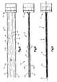
- FIG. 11is a view of a cannula in accordance with a second embodiment of the present invention, shown in an unexpanded condition;
- FIG. 12is an end view of the cannula of FIG. 11 in a fully collapsed condition
- FIG. 13is a view similar to FIG. 12 with the cannula in a partially expanded condition
- FIG. 14is a view similar to FIG. 13 with the cannula in a fully expanded condition
- FIG. 15is a perspective view of the cannula of FIG. 11;
- FIG. 16illustrates the cannula of FIG. 15 with a trocar therein
- FIG. 17illustrates the cannula of FIG. 11 in use
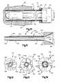
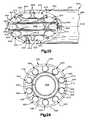
- FIG. 18is a perspective view of a cannula forming another embodiment of the invention.
- FIG. 19is a sectional view of the cannula of FIG. 18, the cannula being shown in a retracted condition;
- FIG. 20is a sectional view of the cannula of FIG. 18, the cannula being shown in an expanded condition;
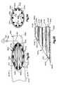
- FIG. 21is an enlarged fragmentary sectional view of a pointed end portion of another embodiment of the cannula of FIG. 1;
- FIG. 22is an end view, taken generally along the line 22 — 22 of FIG. 21, illustrating the relationship between a sheath and wires in the pointed end portion of the cannula;
- FIG. 23is a fragmentary plan view, taken generally along the line 23 — 23 of FIG. 21, further illustrating the construction of the pointed end portion of the cannula;
- FIG. 24is a schematic sectional view illustrating the manner in which the cannula is expanded from the contracted condition of FIG. 22 by insertion of tubular members into the cannula;
- FIG. 25is an enlarged fragmentary schematic illustration depicting the relationship between the contracted cannula of FIGS. 21-23 and body tissue immediately prior to insertion of the contracted cannula into the body tissue;
- FIG. 26is a fragmentary schematic illustration depicting the relationship between the contracted cannula and a blood vessel after the cannula has pierced skin and body tissue adjacent to the blood vessel and prior to piercing of a side wall of the blood vessel;
- FIG. 27is an enlarged fragmentary schematic illustration of a portion of FIG. 26 further illustrating the relationship between the pointed end portion of the cannula and the side wall of the blood vessel;
- FIG. 28is a fragmentary schematic illustration, generally similar to FIG. 26, illustrating the relationship of the cannula to the blood vessel after the cannula has pierced the side wall of the blood vessel and has been inserted into the blood vessel with the cannula in the contracted condition of FIG. 22;
- FIG. 29is a fragmentary schematic illustration, taken generally along the line 29 — 29 of FIG. 28, further illustrating the relationship between the cannula and the blood vessel;
- FIG. 30is a fragmentary schematic illustration, generally similar to FIG. 28, illustrating the relationship between the cannula and the blood vessel when the cannula is in an expanded condition;
- FIG. 31is a schematic illustration, similar to FIG. 29, and taken generally along the line 31 — 31 of FIG. 30;
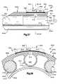
- FIG. 32is an enlarged schematic illustration, generally similar to FIG. 25, illustrating the relationship between another embodiment of the cannula and the skin of a patient immediately prior to piercing of the skin of the patient with the cannula;
- FIG. 33is a fragmentary schematic illustration, generally similar to FIG. 31, illustrating the relationship between another embodiment of the cannula and a blood vessel after the cannula has been inserted into the blood vessel and expanded by fluid pressure;
- FIG. 34is a sectional view, taken along the line 34 — 34 of FIG. 33, further illustrating the relationship between the expanded cannula and the blood vessel;
- FIG. 35is a fragmentary sectional view, generally similar to FIG. 21, illustrating a pointed end portion of another embodiment of the cannula;
- FIG. 36is a fragmentary sectional view, generally similar to FIG. 21, illustrating a pointed end portion of another embodiment of the cannula;
- FIG. 37is an enlarged fragmentary sectional view of a portion of FIG. 36 illustrating the construction of an end portion of the cannula which is expandable when the cannula is in the expanded condition of FIG. 24;
- FIG. 38is a sectional view, taken generally along the line 38 — 38 of FIG. 37, further illustrating the construction of the end portion of the cannula.
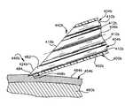
- a cannula 10(FIG. 1) includes an expanding portion 12 and a proximal end portion 14 .
- the expanding portion 12includes a plurality of longitudinally extending wires 16 .
- the wires 16are surrounded for most of their length by an overlying elastic sheath 18 .
- the wires 16define between them a central instrument passage 20 .
- the wires 16are preferably made of a material which is flexible, does not break, and does not stretch.
- a preferred materialis music wire, which is thin gauge steel about 0.015′′ in diameter.
- the use of the term “wire” in this application and its claimsdoes not limit the invention to metal wires.
- the “wires”may also be made of other elongate material such as composites or plastics or other metals.
- the “wires”may also be coated.
- the number of wiresmay be selected as desired. Applicants have found that 8 to 10 wires will suffice for a cannula expandable up to 7 mm OD, and that 12 wires or more may be necessary for a larger cannula. Ten larger diameter wires (0.025′′) may be used rather a larger number of small diameter wires. A greater number of wires 16 can be used if a greater diameter is needed. If not enough wires 16 are used, an instrument (trocar, insert, scope, etc.) inserted through the passage 20 when the cannula 10 is expanded will contact the elastic sheath 18 rather than the wires 16 , at locations between the wires.
- the wires 16are self-aligning. When the cannula 10 is in a contracted condition, the wires 16 may overlap. When the cannula 10 is expanded, the wires 16 straighten out as shown.
- the elastic sheath 18is preferably secured to the wires 16 at both proximal and distal ends, to prevent the sheath's sliding off the wires during insertion and removal of the cannula 10 .
- Rubber cement or cyanoacrylate or a similar adhesivecan be used to bond the sheath 18 to the wires 16 as shown schematically at 24 .
- the elastic sheath 18is preferably made of latex or silicone, or of C-Flex®, a general purpose thermoplastic elastomer sold by Linvatec Corporation of Clearwater, Fla.
- the sheath 18is of a diameter such that it is stressed even when the cannula 10 is fully contracted. Thus, the sheath 18 constantly biases the wires 16 radially inwardly toward the axis 22 of the cannula 10 .
- the wires 16are clamped between an inner ring member 30 and an outer ring member 32 .
- the inner ring member 30has a central opening 34 .
- the inner ring member 30has a clamping surface 36 including a beveled edge 38 and an annular radially extending surface 40 .
- the outer ring member 32has a threaded central opening 42 for receiving a standard luer lock 43 .
- the outer ring member 32has a clamping surface 44 including a beveled edge 46 and an annular radially extending surface 48 .
- the ring members 30 and 32can be made of metal, in which case they can be brazed or welded together.
- the ring members 30 and 32can be made of plastic, in which case then they can be UV joined or joined by adhesive.
- Proximal end portions 50 of the wires 16are trapped between the ring members 30 and 32 .
- the proximal end portions 50 of the wires 16are trapped between the clamping surface 36 of the inner ring 30 and the clamping surface 44 of the outer ring 32 .
- the proximal end portion 52 of the sheath 18is preferably also trapped between the rings 30 and 32 , to secure the sheath proximally.
- the proximal end portion 52 of the sheath 18may be bonded to the wires 16 at a proximal location adjacent the ring members 30 and 32 .
- the proximal end of the cannula expanding portion 12is secured, having a large diameter generally equal to the expanded diameter of the cannula 10 .
- the sheath 18has a longitudinally extending circumferential outer surface 54 (FIG. 7) and a longitudinally extending circumferential inner surface 56 .
- the wires 16engage the circumferential inner surface 56 of the sheath 18 .
- the radially inner surfaces 60 of the wires 16define an annular periphery 62 within which any item inserted in the cannula 10 is disposed.
- the cannula 10when contracted, the cannula 10 is about 2 mm diameter, the size of a 14 ga needle.
- the constructed cannulais about 90 mm long.
- Other useful sizesinclude (i) up to 2.5 mm diameter with a 70 mm length; (ii) up to 7 mm diameter with a 110 mm length; and (iii) up to 11 mm diameter with a 160 mm length.
- the surgeonmakes a small incision in the epidermis. He inserts a narrow trocar such as the trocar 70 (FIGS. 6 and 8) into the central passage 20 of the cannula 10 .
- the pointed end portion 72 of the trocar 70will project distally.
- the shaft portion 74 of the trocar 70is disposed inside the passage 20 .
- the outer surface 76 of the trocar shaft portion 74engages the radially inner surfaces 60 of the wires 16 .
- the proximal end portion 78 of the trocar 70extends proximally from the cannula 10 .
- the end portion 72 of the trocar 70may be blunt in order to push away internal tissue. In this case, a small incision would need to be made through the epidermis.
- the trocar/cannula assemblyis inserted through the incision in the epidermis to the subcutaneous working location. Then, a tubular insert 80 (FIG. 8) is moved distally between the wires 16 of the cannula 10 and the trocar 70 .
- the insert 80is preferably a hollow metal tube at least as large in ID as the OD of the trocar pointed end portion 72 .
- the trocar 70can then be removed from the cannula 10 , leaving the cannula and the insert 80 in place in the tissue.
- the cannula 10is expanded radially outwardly, as seen in a comparison of FIGS. 7 and 8 (which are not necessarily to scale). The tissue around the cannula 10 is also stretched. The surgeon has thus made a larger passage for instruments, along its entire length, without cutting tissue.
- the surgeonremoves the insert 80 .
- the cannula 10collapses radially inwardly because of the elastic sheath and because of the force of the tissue around it. But the tissue opening does not necessarily collapse completely, because of the viscoelastic nature of tissue, which tends to maintain its stretched condition for some time.
- the second insertis a hollow tube larger in diameter than the first insert 80 . Again, the cannula expands radially outwardly, and the tissue stretches.
- the cannulamay then be in the expanded condition shown in FIG. 9, with a full size metal insert 90 within the cannula 80 .
- the insert 90then functions as a normal cannula, allowing insertion and removal of surgical instruments and the like.
- FIG. 11An example is illustrated in FIG. 11 showing a probe 94 extending through the central instrument passage 20 of the cannula 10 having an insert 90 therein.
- the cannula 10has expanded tissue 96 radially outwardly to create a cavity 98 therein.
- the cannula 10is discarded after use to prevent contamination.
- the wires 16have outer surface portions 60 disposed radially inwardly in the cannula 10 and forming contact surfaces for surgical instruments and the like inserted through the central instrument passage 20 of the cannula.
- the sheath 18has an outer circumferential surface 54 engaging tissue when the cannula 10 is in use.
- the wires 16block engagement of instruments inserted through the central instrument passage 20 of the cannula 16 with the elastic sheath 18 .
- the sheath 18blocks engagement of tissue with the wires 16 , and the sheath and the wires block engagement of tissue with any instruments inserted through the cannula 10 .
- the cannula 10expands radially outwardly along substantially its entire length against the bias of the sheath 18 .
- the cannula 10can accommodate through its central instrument passage 20 a surgical instrument or the like having a diameter along its entire length which is greater than the diameter of the cannula in the contracted condition. This is not possible with cannulas which expand only along a portion of their length.
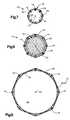
- An expandable cannula 100includes four longitudinally extending members 102 , 104 , 106 , and 108 . Each member includes a longitudinally extending arcuate segment and a widened proximal end portion.
- the members 102 , 104 , 106 , and 108are made of plastic.
- One suitable materialis Delrin® brand plastic.
- the member 102includes a longitudinally extending arcuate segment 110 and a widened proximal end portion 112 .
- the member 104includes a longitudinally extending arcuate segment 114 and a widened proximal end portion 116 .
- the member 106includes a longitudinally extending arcuate segment 118 and a widened proximal end portion 120 .
- the member 108includes a longitudinally extending arcuate segment 122 and a widened proximal end portion 124 .
- the members 102 , 104 , 106 , and 108each subtend an angle of 90°.
- their longitudinally extending arcuate segments 110 , 114 , 118 , and 122form a tubular expandable cannula structure 130 .
- the distal ends 132 of the members 102 , 104 , 106 , and 108are tapered inwardly for ease of entrance through tissue.
- the widened proximal end portions 112 , 116 , 120 , and 124together form a handle for the cannula 100 which also allows entry of an instrument therethrough.
- the end portionshave angled inner surfaces 134 to guide an instrument into the longitudinally extending central instrument passage 136 of the cannula 100 in the direction indicated by the arrow 138 .
- the handle (proximal end) portion of the cannula 100can be configured to attach instruments to it, or to have a cap screwed onto the end to close the cannula.
- the arcuate segments 110 , 114 , 118 , and 122are surrounded for most of their length by an overlying elastic sheath 140 .
- the elastic sheath 140is secured to the segments 110 , 114 , 118 , and 122 at proximal and distal locations 142 and 144 , to prevent the sheath's sliding off the segments during insertion and removal of the cannula 100 .
- Rubber cement or cyanoacrylate or a similar adhesivecan be used to bond the sheath 140 to the segments.
- the elastic sheath 140is preferably made of latex or silicone, or of the C-Flex® material described above.
- the sheath 140is of a diameter such that it is stressed even when the cannula 100 is fully contracted. Thus, the sheath 140 constantly biases the segments radially inwardly toward the center of the cannula 100 .
- One cannula that has been constructedis 90 mm in length, and about 5 mm in diameter when aligned in a tube form as shown in FIGS. 12-14.
- the memberscan collapse (overlap onto themselves as shown in FIG. 12) into a smaller diameter.
- the cannulacan expand to about 12+mm OD.
- the surgeonmakes a small incision in the epidermis. He inserts a narrow trocar such as the trocar 70 (FIG. 16) into the central passage 136 of the cannula 100 .
- the pointed end portion 72 of the trocar 70will project distally.
- the shaft portion 74 of the trocar 70is disposed inside the passage 136 .
- the proximal end portion 78 of the trocar 70extends proximally from the cannula 100 .
- a trocarshould be used with the cannula 100 only when needed.
- the distal end portion of the cannula 100is preferably used alone to push through internal tissue once an epidermal incision has been made.
- the trocar/cannula assemblyis inserted through the incision in the epidermis to the subcutaneous working location. Then, a tubular insert 80 (FIG. 14) is inserted longitudinally between the cannula 100 and the trocar 70 .
- the insert 80is preferably a hollow metal tube at least as large in ID as the OD of the trocar pointed end portion 72 .
- the trocar 70can then be removed from the cannula 100 , leaving the cannula and the insert 80 in place in the tissue.
- the outer surface of the insertengages longitudinally extending radially inner edges 148 of the members 102 , 104 , 106 , and 108 .
- the cannula 100is expanded radially outwardly, as seen in a comparison of FIGS. 13 and 14 (which are not necessarily to scale).
- the four members 102 , 104 , 106 , and 108move radially outwardly away from each other.
- the passage 136is enlarged.
- the tissue around the cannula 100is also stretched. The surgeon has thus made a larger passage for instruments, along its entire length, without cutting tissue.
- the surgeonremoves the insert 80 .
- the cannula 100collapses radially inwardly because of the elastic sheath and because of the force of the tissue around it. But the tissue opening does not necessarily collapse completely, because the tissue is viscoelastic.
- the second insert 90is a hollow tube larger in diameter than the first insert 80 .
- the cannula 100expands further radially outwardly, and the tissue stretches.
- the cannulamay then be in the expanded condition shown in FIG. 17, with the insert 90 within the cannula 100 .
- the cannula 100can then be removed proximally, leaving the insert in place.
- the insertthen functions as a normal cannula, allowing insertion and removal of surgical instruments and the like such as the probe illustrated schematically at 94 .
- the cannula 100expands radially outwardly along substantially its entire length against the bias of the sheath 130 .
- the cannula 100can accommodate through its central instrument passage 136 a surgical instrument or the like having a diameter along its entire length which is greater than the diameter of the cannula in the contracted condition. This is not possible with cannulas which expand only along a portion of their length.
- a first, smaller sizewould extend from an OD of 2.5 mm to an ID of 7 mm, being about 70 mm in length.
- a second, larger sizewould extend from an OD of 6 mm to an ID of 12 mm, being about 150 mm in length.
- the expandable cannulas of the present inventionmay be designed to selectively expand at a location at or near the distal end. This is illustrated in FIGS. 18-20.
- An expandable cannula 300 similar to the expandable cannula 10 (FIGS. 1-9)includes a plurality of longitudinally extending wires 302 .
- the cannula 300includes an inflatable sheath 304 .
- the sheath 304includes an inner sheath member 306 and an outer sheath member 308 .
- the inner sheath member 306is of a double-walled construction, including an inner wall 310 and an outer wall 312 .
- An inflation volume 314separates the inner wall 310 and the outer wall 312 .
- Fluid under pressuresuch as air, saline, etc. may be introduced into the inflation volume 314 through a fluid port 316 .
- the inner sheath member 306overlies the wires 302 .
- the outer wall 312 of the inner sheath member 306expands radially outwardly, as shown in FIG. 20 . Radially outward expansion of the outer wall 312 of the inner sheath member 306 is limited by the outer sheath member 308 .
- the outer sheath member 308is a single-layer sheath overlying the inner sheath member 306 .
- a notch 320is cut out of the outer sheath member 308 .
- the outer wall 312 of the inner sheath member 306can expand radially outwardly only at the location of the notch 320 in the outer sheath member 308 .
- the notch 320may be placed at or near the distal end of the cannula 300 . This will stabilize the cannula 300 in the tissue, at the closest possible location to the work area off the distal end of the cannula.
- each of the wiresincludes a core and a coating or jacket which is integrally formed as one piece with the plastic sheath of the cannula. It is contemplated that the embodiment of the cannula illustrated in FIGS. 21-31 will be particularly advantageous for use in establishing communication with interior of a vessel, such as a sac, organ, tube, duct or canal. However, the cannula may be used to establish communication with any desired portion of the human body.
- the cannula 400(FIGS. 21, 22 and 23 ) has the same general construction as the cannula 10 of FIGS. 1-10.
- the cannula 400includes an elastic sheath 402 which encloses a plurality of longitudinally extending wires 404 .
- the wiresdefine between them a central passage 406 through which instruments may be inserted into a human body or fluid may be conducted into the human body.
- the sheath 402 and wires 404are clamped between ring members in the same manner illustrated in FIGS. 2 and 3 for the cannula 10 .
- each of the wires 404includes a core 410 (FIG. 22) which is at least partially enclosed by a coating or jacket 412 .
- the cores 410 and jackets 412extend between opposite ends of the sheath 402 .
- the cores 410 and jackets 412extend from a generally circular opening 416 (FIG. 21) at the distal or leading end of the sheath 402 to clamping ring members at the proximal end (not shown) of the sheath.
- each of the jackets 412is integrally formed as one piece with the sheath 402 .
- each of the jackets 412is formed of the same elastic material as the sheath 402 .
- the elastic polymeric material of the sheath and the jackets 412may be molded or extruded around the cores 410 during formation of the cannula 400 .
- Each of the jackets 412has a longitudinal central axis which extends parallel to a longitudinal central axis 418 of the cannula 400 .
- the jackets 412extend throughout the entire length of the sheath 402 . Since the jackets 412 are integrally formed as one piece with the sheath 402 , the wires 404 are maintained in a parallel relationship with the longitudinal central axis 418 of the cannula 400 .
- the parallel wires 404extend from the opening 416 at the distal end of the sheath 402 to the location where the proximal end of the sheath is clamped between ring members in a manner similar to that illustrated in FIGS. 2 and 3. The wires 404 do not intersect.
- Central cores 410 of the wires 404may be formed of any desired material.
- the cores 410are formed of metal.
- the cores 410are formed of music wire, that is a thin gauge steel of about 0.015 inches in diameter.
- the cores 410could be formed of composite polymeric materials if desired.
- the cores 410could be formed by a matrix of polymeric material strengthened by longitudinally extending carbon fibers.
- the parallel cores 410 of the wires 404have a cylindrical configuration.
- each of the cores 410has a circular cross sectional configuration as viewed in a plane extending perpendicular to a longitudinal central axis of the core.
- the sheath 402engages longitudinally extending side portions of the cores 410 .
- the longitudinally extending side portions of the cores 410 which are engaged by the sheath 402face radially outward away from the central axis 418 of the cannula 400 .
- the surface portions of the cores 410 which do not engage the sheath 402are enclosed by the jackets 412 . Since the jackets 412 are integrally formed as one piece with the sheath 402 , there is no precise line of demarcation between the jackets and the sheath. However, the jackets 412 extend inward from the sheath 402 toward the central axis 418 of the cannula 400 and cooperate with the sheath to enclose each of the cores 410 . If desired, the jackets 412 could extend completely around the cores 410 .
- Circular axial end faces 424 of the cores 410are exposed at opposite ends of the sheath 402 .
- the circular end faces 424 (FIGS. 22 and 23) of the coresare visible.
- the jackets 412extend from the end faces 424 of the cores 410 to the opposite end of the sheath 402 .
- the cannula 400is expandable throughout its length from a contracted condition (FIG. 22) to an expanded condition (FIG. 24) in the same manner as in which the cannula 10 of FIGS. 1-10 is expandable.
- a first cylindrical tubular member 430is axially inserted into the central passage 406 through the proximal end portion of the cannula 400 (FIG. 24 ).
- a cylindrical outer side surface 432 on the tubular member 430slides along the wires 404 toward the distal or leading end of the cannula.
- the outer side surface 432 of the tubular member 430slides on surfaces of the jackets 412 which enclose the cores 410 of the wires 404 .
- the wires 404are forced radially outward away from the longitudinal central axis 418 of the cannula.
- the cylindrical outer side surface 432 of the member 430applies radially outward force against the wires 404 .
- This radially outward forceis transmitted through the wires 404 to the sheath 402 .
- the elastic material of the sheath 402is resiliently stretched and the distance between the wires 404 increases.
- the first tubular member 430has a length which is greater than the length of the sheath 402 and extends axially outward from opposite ends of the sheath.
- the cannula 400may be used with the tubular member 430 holding the cannula in an expanded condition. However, it is believed that it may be desirable to further expand the cannula 400 . Therefore, a second cylindrical tubular member 436 is inserted into the cannula 400 through the proximal end of the cannula to further expand the cannula.
- the second tubular member 436has an inside diameter which is larger than the outside diameter of the first cylindrical tubular member 430 .
- a cylindrical outer side surface 438 on the second tubular member 436slides along the wires 404 .
- the second tubular member 436forces the wires 404 radially outward away from the cylindrical outer side surface 432 of the first tubular member 430 .
- the elastic material of the sheath 402is further resiliently stretched by the force applied against the wires 404 by the tubular member 436 .
- the distance between the parallel wires 404increases. Sliding of the tubular member 436 from the proximal end to the distal end of the cannula 400 is relatively easy since the tubular member slides along the jackets 412 on the wires 404 and does not engage the inner side surface of the sheath 402 .
- the second cylindrical tubular member 436extends axially outward from opposite ends of the sheath 402 .
- the first tubular membercan be axially withdrawn from the cannula 400 . This results in the cylindrical central passage 406 through the cannula 400 having a diameter equal to the inside diameter of the relatively large second tubular member 436 .
- a still larger tubular membermay be telescopically inserted into the cannula 400 around the second tubular member 436 to further expand the cannula and increase the size of the central passage 436 through the cannula. It is possible to expand the cannula 400 to any one of may different sizes depending upon the size of the tubular member which is used to apply force against the wires 404 and resiliently stretch the sheath 402 of the cannula. It is believed that it will be preferred to have the extent of expansion of the sheath 402 be less than the elastic limit of the material forming the sheath.
- the sheath 402Since the elastic limit of the material forming the sheath 402 is not exceeded by expanding the cannula 400 by insertion of the members 430 and 436 , when the members are withdrawn from the cannula, the sheath will resiliently contract back to the original size shown in FIG. 22 . Thus, to contract the cannula 400 back to its original size, it is merely necessary to axially pull the tubular member 436 out of the proximal end of the cannula. The elastic material of the sheath 402 will move the wires 404 radially inward toward the longitudinal central axis 418 of the cannula and return the cannula back to the retracted condition shown in FIG. 22 .
- the cannula 400has a pointed distal end portion 442 (FIG. 21 ).
- the pointed distal end portion 442 of the cannula 400facilitates piercing of body tissue with the cannula.
- the pointed end portion 442is formed by cutting the materials of the sheath 402 and wires 404 at an acute angle to the longitudinal central axis 418 of the cannula 400 .
- the pointed end portion 442 of the cannula 400is formed by cutting the material of the sheath 402 and wires 404 at an angle of approximately 30° to the longitudinal central axis 418 of the cannula.
- the pointed end portion 442could be skewed at a different angle relative to the longitudinal central axis 418 of the cannula 400 if desired.
- the ends of the wires 404 and the end of the sheath 402cooperate to provide the cannula 400 with an end portion 442 which can cut body tissue when the end portion of the cannula is pressed against the body tissue.
- the sheath 402may advantageously be cut away adjacent to an apex 446 of the pointed end portion 442 .
- a bevelled surface 448is formed in the material of the sheath 402 adjacent to the apex 446 of the pointed end portion 442 .
- the bevelled surface 448makes the pointed end portion 442 of the cannula sharper to facilitate severing the body tissue.
- the bevelled surface 448extends outward to a leading end of a wire 404 which extends through the central part of the apex 446 of the pointed end portion 442 of the cannula 400 .
- the cylindrical cores 410 of the parallel wires 404are formed by thin gauge steel wire.
- the leading end of the core 410 of the wire 404extends through the apex 446 of the pointed end portion 442 of the cannula 400 .
- the leading end of the core 410 of the wire 404 through the apex 446provides a relatively sharp cutting edge at the axially outer end of the cannula 400 . This sharp cutting edge can readily penetrate relatively tough body tissue.
- the pointed end portion 442 of the contracted cannula 400When the pointed end portion 442 of the contracted cannula 400 is pressed against an imperforate surface area on body tissue, force is transmitted axially through the wires 404 and through the sheath 402 to the body tissue.
- the apex 446 of the pointed end portionpenetrates the body tissue and initiates the formation of an opening in the body tissue.
- the initiating of the opening in the body tissueis facilitated by having the exposed relatively sharp end of the core 410 of the wire 404 which extends through the apex 446 of the pointed end portion 442 of the contracted cannula 400 engage the body tissue to initially cut the imperforate surface area of the body tissue.
- the leading edge portions of the sheath disposed adjacent to opposite sides of the wire 404 through the apex 446 of the cannula 400are then effective to sever body tissue to increase the size of the opening in the body tissue.
- the leading end portions of additional wires 404 and leading edges of segments of the sheath 402 disposed between the wiressever the body tissue to increase the size of the opening.
- the sheath 402 and ends of the wires 404cooperate to form an opening in the body tissue at a location where there was no natural opening.
- the size of the opening formed in the body tissue by the pointed end portion 442 of the cannula 400increases until the opening is large enough to accept the cylindrical outer side surface of the cannula when it is in the contracted condition of FIG. 22 .
- the cannula 400is expanded from the contracted condition of FIG. 22 to the expanded condition of FIG. 24 .
- the viscoelastic material of the body tissueis resiliently stretched and the size of the small opening formed by the cannula 400 in its contracted condition is increased.
- surgical tools and/or optical instrumentscan be inserted through the cylindrical passage 406 within the second tubular member 436 and expanded cannula 400 .
- the viscoelastic body tissuealso contracts. Therefore, the size of the wound in the body tissue is minimized.
- the cannula 400will have many different uses, including the establishment of communication with the interior of many different types of vessels in a human body.
- the cannulacould be used to establish communication with the interior of a vessel such as a lung, heart, endolymphatic duct or sac, a hernial sac, or a bladder.
- the cannula 400will be used as a passage through body tissue for many different types of instruments and/or fluids.
- the cannula 400may be used to facilitate laproscopic or arthroscopic surgery.
- the cannula 400will be particularly advantageous in establishing communication with the interior of a blood vessel.
- the cannula 400can be used to establish communication with the interior of a blood vessel in a human body for an intravenous infusion.
- the pointed end portion 442 of the cannula 400is used to pierce an imperforate surface area on the skin 454 (FIG. 25) of a human body.
- the pointed end portion 446 of the cannula 400pierces an imperforate surface area on a side wall 456 of a vein or blood vessel 458 (FIGS. 26, 27 and 28 ).
- the cannula 400is used to initiate the formation of openings in the skin 454 and side wall 456 of the blood vessel 458 at locations where there is no naturally occurring opening and without the necessity of making an incision prior to insertion of the cannula.
- An intravenous infusion of a suitable liquid preparationcan then be conducted through the cannula 400 into the vein.
- the apex 446 of the pointed end portion 442 of the contracted cannula 400is first pressed against an outer side surface 464 of the skin 454 (FIG. 25 ). Engagement of the end face 424 of the core 410 of the wire 404 which extends through the apex 446 of the pointed end portion 442 (FIGS. 21 and 23) of the cannula 400 punctures the outer side surface 464 of the skin 454 under the influence of force transmitted axially through the cannula 400 .
- the pointed end portion 442 of the cannula 400could have the sheath 402 configured in such a manner, that is, by elimination of the bevelled surface 448 , so as to have the sheath itself initiate the formation of the opening in the skin 464 .
- the size of the opening in the skinis increased.
- a cylindrical outer side surface 468 of the sheath 402enters the opening in the skin.
- the cannula 400is in the contracted condition of FIG. 22 . Therefore, a relatively small opening in the skin 454 can accommodate the cannula 400 .
- the cannula 400After the cannula 400 has pierced the skin 454 , the cannula is pressed toward the blood vessel 448 and pierces the body tissue 460 (FIG. 26 ). The cannula 400 is moved through the body tissue 460 until the pointed end portion 446 of the cannula 400 engages the side wall 456 of the blood vessel 458 . The pointed leading end portion 442 of the cannula 400 is then pressed firmly against the side wall 456 of the blood vessel 458 (FIG. 27 ).
- the axial force transmitted through the contracted cannula 400causes the axially tapered leading end of the core 410 of the wire 404 which extends through the apex 446 (FIG. 21) of the pointed end portion 442 of the cannula to initiate the formation of an opening at an imperforate outer side surface 472 (FIG. 27) of the side wall 456 of the blood vessel 458 .
- Continued axial movement of the cannula 400results in the leading end portion 442 of the cannula piercing the side wall 456 of the blood vessel 456 . Since the cannula 400 is in the contracted condition of FIG. 22 when the side wall 456 of the blood vessel 458 is pierced, a relatively small opening 476 is formed in the side wall 456 of the blood vessel 456 by the cannula 400 .
- the cannula 400is shown in FIG. 25 as being oriented with its longitudinal central axis at an angle of approximately 30° relative to the outer side surface 464 of the skin 454 as the skin is pierced, it is contemplated that it may be desired to have the cannula oriented at an angle of approximately 45° relative to the outer side surface 464 of the skin 454 when the skin is pierced by the cannula.
- the cannulais shown as being oriented relative to the blood vessel 458 with the longitudinal central axis of the cannula extending at an angle of approximately 30° relative to the outer side surface 472 of the blood vessel 458 .
- the cannulaoriented at a smaller angle relative to the outer side surface 472 of the blood vessel 458 as the blood vessel is pierced.
- Reducing the angle between the longitudinal central axis of the cannula 400 and the outer side surface 472 of the blood vessel 458 prior to piercing the blood vesselfacilitates piercing the side wall 456 of the blood vessel 458 without pushing the cannula 400 clear through the blood vessel.
- the cannula 400is moved axially along the blood vessel (FIG. 28) to increase the telescopic relationship between the blood vessel and the cannula.
- FIG. 28the cannula 400 has been shown in FIG. 28 as being inserted for only a relatively a small distance into the blood vessel 458 , it is contemplated that the cannula may be inserted for a substantial distance into the blood vessel.
- the cannula 400may be moved along the blood vessel 458 to another vessel, such as a sac or organ.
- the cannula 400Since the cannula 400 is in the contracted condition of FIG. 22, the cannula will have a small outside diameter (FIG. 29) and will be relatively easy to move along the blood vessel 458 .
- the contracted cannula 400will form a relatively small opening 476 in the side wall 456 of the blood vessel 458 .
- the contracted cannula 400may have a sufficiently large central passage 406 for some purposes. For example, an intravenous injection of a small dose of medicine could be made through the contracted cannula 400 if desired.
- the cannula 400will be advantageously used in circumstances requiring a relatively large passage 406 for communication with the interior of the blood vessel 458 and/or a vessel connected with the blood vessel 458 .
- the cannula 400When a relatively large passage 406 is required through the cannula 400 to communicate with the interior of the blood vessel 458 , the cannula 400 is expanded from the contracted condition of FIG. 22 to the expanded condition of FIG. 24 by the sequential insertion of members into the cannula.
- the first tubular member 430(FIG. 24) is inserted into the cannula 400 to increase the diameter of the outer side surface 468 of the cannula and to effect a relatively small radial expansion of the side wall 456 of the blood vessel 458 .
- the outer side surface 468 of the cannulais pressed against edge portions of the opening 476 to increase the size of the opening.
- the outer side surface 468 of the cannula 400is pressed against the edge portions of the opening in the skin 454 to increase the size of the opening in the skin.
- the outer side surface 468 of the cannula 400also applies force against the inner side surface of the blood vessel 458 to expand the blood vessel.
- the tubular member 436(FIGS. 24, 30 and 31 ) is then inserted into the cannula 400 to further expand the cannula and the blood vessel 458 .
- forceis transmitted from the outer side surface 468 of the cannula to an inner side surface of the blood vessel 458 to radially expand the blood vessel.
- the openings in both the blood vessel 458 and skin 454are expanded.
- the diameter of the blood vesselcan be substantially increased by expanding the cannula 400 from the contracted condition of FIGS. 28 and 29 to the expanded condition of FIGS. 30 and 31.
- expanding the side wall 456 of the blood vessel 458enable fluid (liquid) to be conducted at a relatively high flow rate into the blood vessel. The fluid is conducted through the tubular member 436 and the cannula 400 into the blood vessel 458 .
- expansion of the side wall 456 of the blood vessel 458 along with the cannula 400enables surgical instruments and/or optical instruments to be inserted through the cannula into the blood vessel.
- the contracted cannula 400is moved along the blood vessel into another vessel, such as a sac or organ, before being expanded, the surgical instruments inserted through the central passage of the expanded cannula can be used within the sac or other body part.
- the core 410 of the wire 404 which extends into the apex 446 of the pointed end portion 442is co-extensive with the sheath 402 .
- the core of the wire which extends into the apex of the pointed end portion of the cannulaextends beyond the sheath of the cannula to facilitate engagement of the core with the wire with body tissue. Since the embodiment of the invention illustrated in FIG. 32 is generally similar to the embodiment of the invention illustrated in FIGS. 21-31, similar numerals will be utilized to designate similar components, the suffix letter “b” being associated with the numerals of FIG. 32 to avoid confusion.
- the cannula 400 bhas a cylindrical sheath 402 b which encloses a plurality of longitudinally extending wires 404 b .
- Each of the wires 404 bhas a linear core 410 b which is enclosed by a jacket 412 b .
- the jacket 412 bis integrally formed as one piece with the sheath 402 b and cooperates with the sheath to enclose one of the cores 410 b .
- the pointed end portion 442 bhas a circular opening 416 b.
- a core 410 b of one of the wires 404 bextends past the bevelled outer edge surface 448 b of the sheath 402 b .
- an end portion 482 of the core 410 b of the wire 404 bextends past the opening 416 b to the central passage 406 b through the cannula 400 b .
- the outwardly projecting core 410 bhas a pointed end portion 484 which projects axially outwardly from the sheath 402 b.
- the pointed end portion 484 of the wire core 410 bengages the outer side surface 464 b of the skin before the sheath 402 b engages the skin. This results in the sharp outer end portion 484 of the core 410 b piercing the outer side surface 464 b of the skin 454 b before the skin is engaged by the sheath 402 b .
- the pointed end portion 484 of the core 410 bBy piercing the outer side surface 464 b of the skin 454 b with the pointed end portion 484 of the core 410 b , the forming of an opening in the skin by the contracted cannula 400 b is facilitated.
- the cannula 400has a circular cross sectional configuration as viewed in a plane extending perpendicular to a longitudinal central axis 418 of the cannula (FIG. 22 ). It is contemplated that the cross sectional area of the cannula may be maximized by forming the cannula with an oval cross sectional configuration as viewed in a plane extending perpendicular to a longitudinal central axis of the cannula.
- the cannulais expanded under the influence of fluid pressure rather than by inserting members into the cannula in the manner described in conjunction with FIG. 24 .
- members having an oval cross sectional configurationcould be inserted into the cannula of FIGS. 33 and 34 to expand the cannula. Since the cannula of FIGS. 33 and 34 have the components of the same construction as the components of the cannula of FIGS. 21-31, similar numerals will be utilized to identify similar components, the suffix letter “c” being associated with the numerals of FIGS. 33 and 34 to avoid confusion.
- the cannula 400 cis inserted into a blood vessel 458 c in the manner illustrated in FIGS. 33 and 34.
- the cannula 400 cincludes an elastic sheath 402 c .
- the sheath 402 cencloses longitudinally extending wires 404 c .
- the wires 404 cinclude cores 410 c and jackets 412 c .
- the jackets 412 care integrally formed as one piece with the sheath 402 c.
- the cannula 400 chas an oval configuration (FIG. 34) as viewed in across sectional plane extending perpendicular to a longitudinal central axis of the cannula.
- the major axis of the oval cross section of the cannulais aligned with the longitudinal central axis of the blood vessel 458 c at the location where the cannula extends through an opening in the side wall of the blood vessel.
- the longitudinal central axis of the blood vessel 458 cis disposed in the same plane as the major cross sectional axis of the oval cross section (FIG. 34) of the cannula.
- the minor axis of the oval cross section of the cannulaextends radially relative to the blood vessel 458 c.
- the major axis of the opening formed in the blood vessel 458 cextends longitudinally along the side wall 456 c of the blood vessel (FIG. 33 ).
- the opening which is formed in the outer side surface 472 c of the blood vessel 458 cis relatively long in a lengthwise direction along the blood vessel.
- the opening formed in the outer side surface 472 c of the blood vessel 458 cis relatively small in a direction extending circumferentially around the blood vessel.
- the cannula 400 cpierces the side wall 456 c of the blood vessel 458 c , the cannula is in a contracted condition in which it has a substantially smaller cross sectional configuration than is illustrated in FIG. 33 .
- the relationship of the contracted cannula 400 c to the blood vessel 458 c when the cannula pierces the side wall 456 c of the blood vesselis similar to the relationship illustrated in FIG. 29 for the cannula 400 to the blood vessel 458 .
- the contrated cannula 400 cwill have a major cross sectional axis which is aligned with the longitudinal central axis of the blood vessel 458 c (FIG. 33 ).
- the minor cross sectional axis of the contracted cannula 400 cwill have an extent which is equal to the diameter of the contracted cannula 400 of FIGS. 21-31.
- the cannula 400 cis expanded throughout its length under the influence of fluid pressure.
- a pump 490is connected with the central passage 406 c in the cannula 400 c through a valve 492 and a conduit 494 .
- Relatively high pressure fluidis discharged from the pump 490 through the valve 492 and conduit 494 into the central passage 406 c in the contracted cannula 400 c .
- This fluid pressureis applied against an inner side surface of the sheath 402 c and the wires 404 c.
- the fluid pressure inside the cannula 400 cis effective to cause the elastic material of the sheath 402 c to expand from a contracted condition to an expanded condition. As this occurs, the size of the opening formed in the viscoelastic material of the blood vessel 458 c is enlarged. In addition, the outer side surface of the cannula 400 c presses against the inner side surface of the side wall 456 c to expand the blood vessel 458 c downstream from the location where the cannula enters the blood vessel.
- the fluid from the pump 490forms an intravenous infusion of a liquid solution to the blood vessel 458 c .
- the cannula 400 ccould be expanded by using tubular members having an oval cross sectional configuration in the manner described in conjunction with FIG. 24 . It should be understood that fluid pressure may be used to expand the cannula 400 of FIGS. 21-31 if desired.
- the end face or surfaces 424 on the core 410 of the wires 404are exposed (FIGS. 22 and 23 ).
- the jackets 412enclose the cores 410 throughout the length of the cores.
- the jackets 412do not cover the end surfaces 424 of the cores 410 . Therefore, the end surfaces 424 of the cores 410 are exposed at the pointed end portion 442 of the cannula 400 .
- the jackets around the corescover the end surfaces of the cores. Since the embodiment of the invention illustrated in FIG. 35 is generally similar to the embodiment of the invention illustrated in FIGS. 21-31, similar components will be identified with similar numerals, the suffix letter “d” being associated with the numerals of FIG. 35 to avoid confusion.
- a cannula 400 dincludes an elastic sheath 402 d .
- the sheath 402 dencloses a plurality of longitudinally extending wires 404 d .
- the cannula 400 dhas a longitudinally extending central passage 406 d.
- Each of the wires 404 dincludes a core 410 d and a jacket 412 d which extends around the core 410 d .
- Each of the jackets 412 dis integrally formed as one piece with the sheath 402 d .
- Each of the jackets 412 dextends between opposite ends of the sheath 402 d.
- the jacket 412 d around each of the cores 410 dextends across an axially outer end face 424 d of a core 410 d .
- the cores 410 d of the wires 404 dare completely enclosed by cooperation between the jackets 412 d and the sheath 402 d .
- the jackets 412 dinclude end sections 502 which extend across the end surfaces 424 d of the cores 410 d of the wires 404 d . This results in the cannula 400 d having a pointed end portion 442 d with an apex 446 d which is formed by the sheath 402 d.
- the pointed apex 446 d of the end portion 442 d of the cannulaengages the body tissue.
- the apex 446 d of the pointed end portion 442 dis formed by the elastic material of the sheath 402 d and jackets 412 d .
- the cores 410 ddo not engage the body tissue as the cannula hood is inserted into the body tissue.
- the pointed end of the sheath 402 dinitiates the formation of the opening in the body tissue.
- the wires 404 dstiffen the elastic material of the sheath 402 d to enable force to be transmitted through the cannula 400 d to the axially outer end of the sheath.
- an end portion of the cannula 300is expandable outward of the outer sheath 308 and the inner wall 310 .
- the cannulaalso has an end portion which is expandable outward of an outer side surface of a sheath to engage body tissue. Since the embodiment of the invention illustrated in FIGS. 36, 37 and 38 is generally similar to the embodiment of the invention illustrated in FIGS. 21-31, similar numerals will be utilized to designate similar components, the suffix letter “e” being associated with the numerals of FIGS. 36, 37 and 38 to avoid confusion.
- a cannula 400 ehas an elastic sheath 402 e .
- the sheath 402 eencloses a plurality of longitudinally extending wires 404 e .
- the cannula 400 ehas a longitudinally extending central passage 406 e.
- Each of the wires 404 eincludes a core 410 e and a jacket 412 e (FIG. 38 ).
- Each of the jackets 412 eis integrally formed as one piece with the sheath 402 e .
- Each of the jackets 412 eextends between opposite ends of the sheath 402 e.
- the pointed end portion 442 e(FIG. 36) of the cannula 400 e engages the body tissue.
- the apex 446 e of the pointed end portion 442 epenetrates the body tissue and initiates the formation of an opening in the body tissue at an imperforate surface area on the body tissue.
- the initiating of the opening in the body tissueis facilitated by having an exposed relatively sharp end portion of a core 410 e of a wire 404 e which extends through the apex 446 e of the pointed end portion 442 e of the contracted cannula 400 e engage the body tissue to initially cut the imperforate surface area of the body tissue.
- leading edge portions of the sheath 402 e disposed adjacent to opposite sides of the wire 404 e through the apex 446 e of the cannula 400 eare then effective to sever body tissue to increase the size of the opening in the body tissue.
- the leading end portions of additional wires 404 e and leading edges of segments of the sheath 402 e disposed between the wiressever the body tissue to increase the size of the opening.
- the size of the openingis increased until it is large enough to accept the cylindrical outer side surface 468 e of the cannula 400 e when the cannula is in the contracted condition.
- the cannula 400 eis expanded by inserting a tubular cylindrical member 430 e (FIG. 38) into the contracted cannula 400 e .
- the sheath 402 eis resiliently expanded and the cross sectional size of the longitudinally extending array of wires 404 e is increased.
- the cannula 400 ecould be further expanded by the insertion of a second tubular member, corresponding to the tubular member 436 of FIG. 24 .
- a portion 600 of the pointed end portion 442 e of the cannulais expandable outward of an outer side surface 468 e of the sheath 402 e .
- the portion 600is expandable from the configuration shown in solid lines in FIGS. 37 and 38 to the configuration shown in dashed lines in FIGS. 37 and 38. This enables the portion 600 of the cannula 400 e to engage body tissue and hold the cannula in place in the body tissue.
- both the cannula sheath 402 e and the portion 600 of the cannulaare contracted.
- the cannula sheath 402 eis expanded by either fluid pressure or by insertion of the tubular member 430 e .
- the portion 600 of the cannula 400 eis then expanded radially outward from the cylindrical sheath 402 e to grip the inner side surface of the vein. It is contemplated that in certain circumstances it may not be necessary to expand the sheath 402 e and the portion 600 will be expanded while the sheath is contracted.
- the portion 600 of the cannula 400 eincludes a resilient panel 604 (FIGS. 37 and 38) which is disposed in a rectangular recess 606 formed in the sheath 402 e .
- a resilient panel 604FIGS. 37 and 38
- an arcuate outer side surface 608 of the panel 604is aligned with the outer side surface 468 e of the sheath 402 e.
- the panel 604cooperates with the sheath 402 e to form a variable volume chamber 610 in the side wall of the sheath.
- the panel 604is formed of a polymeric material having a substantially greater elasticity than the material of the sheath 402 e .
- the elasticity of the material of the panel 604enables the panel to be resiliently expanded from the position shown in solid lines in FIGS. 37 and 38 to the position shown in dashed lines and subsequently retracted.
- the chamber 610is connected in fluid communication, through an opening 612 in the sheath 402 e with a conduit 614 .
- the conduit 614has a side wall 616 which is integrally formed with the sheath 402 e .
- the side wall 616 of the conduit 614 and the sheath 402 ecooperate to form a cylindrical passage 620 which extends between opposite ends of the sheath 402 e .
- An axially outer or distal end portion of the conduit 620is blocked by a pointed segment 622 of a metal core 410 e (FIG. 37) of a wire.
- the core 410 eis fixedly secured, by adhesive, in the passage 620 to block fluid flow through the outer end of the passage.
- the passage 620extends to the opposite or proximal end of the cannula 400 e .
- the proximal end of the passage 620is connected with a pump 626 (FIG. 37) through a valve 628 . Since the segment 622 of a wire core 410 e blocks the axially outer or distal end of the passage 620 , any fluid which flows through the valve 628 into the passage 620 must flow into the chamber 610 .
- the side wall 616 of the conduit 614is formed in the same manner and has the same size as the jackets 412 e of the wires 404 e .
- a removable coreis provided at the location where the passage 620 is to be formed.
- conduit 614being disposed in the longitudinal array of wires 404 e and having the same size as one of the wires.
- the outer side surface of the tubular memberslides along the side wall 616 of the conduit 614 in the same manner as in which the tubular member slides along the jackets 412 e of the wires 404 e . Therefore, force is transmitted from the tubular member 430 e through the conduit 614 to the sheath 402 e to expand the sheath when the tubular member is inserted into the cannula 400 e.
- the recess 606is formed in the side wall of the sheath 402 e .
- the panel 604is electron beam welded or otherwise secured to the sheath.
Landscapes
- Health & Medical Sciences (AREA)
- Life Sciences & Earth Sciences (AREA)
- Animal Behavior & Ethology (AREA)
- Veterinary Medicine (AREA)
- Public Health (AREA)
- Engineering & Computer Science (AREA)
- Biomedical Technology (AREA)
- Heart & Thoracic Surgery (AREA)
- General Health & Medical Sciences (AREA)
- Anesthesiology (AREA)
- Hematology (AREA)
- Pulmonology (AREA)
- Biophysics (AREA)
- Surgery (AREA)
- Pathology (AREA)
- Nuclear Medicine, Radiotherapy & Molecular Imaging (AREA)
- Medical Informatics (AREA)
- Molecular Biology (AREA)
- Surgical Instruments (AREA)
- Media Introduction/Drainage Providing Device (AREA)
Abstract
Description
Claims (72)
Priority Applications (9)
| Application Number | Priority Date | Filing Date | Title |
|---|---|---|---|
| US08/470,142US6338730B1 (en) | 1993-02-04 | 1995-06-06 | Method of using expandable cannula |
| US09/084,627US6056772A (en) | 1993-02-04 | 1998-05-26 | Method and apparatus for positioning a suture anchor |
| US09/533,076US6364897B1 (en) | 1993-02-04 | 2000-03-22 | Method and apparatus for positioning a suture anchor |
| US09/992,209US6613038B2 (en) | 1993-02-04 | 2001-11-16 | Method of using expandable cannula |
| US09/992,211US6814715B2 (en) | 1993-02-04 | 2001-11-16 | Expandable cannula |
| US10/078,030US6942684B2 (en) | 1993-02-04 | 2002-02-19 | Method and apparatus for positioning an anchor member |
| US10/242,205US20030014068A1 (en) | 1993-02-04 | 2002-09-12 | Expandable cannula |
| US11/169,475US20050240227A1 (en) | 1993-02-04 | 2005-06-29 | Method and apparatus for positioning an anchor member |
| US11/930,332US20080051734A1 (en) | 1993-02-04 | 2007-10-31 | Expandable cannula |
Applications Claiming Priority (3)
| Application Number | Priority Date | Filing Date | Title |
|---|---|---|---|
| US08/013,942US5320611A (en) | 1993-02-04 | 1993-02-04 | Expandable cannula having longitudinal wire and method of use |
| US08/254,368US5573517A (en) | 1993-02-04 | 1994-06-06 | Expandable cannulas |
| US08/470,142US6338730B1 (en) | 1993-02-04 | 1995-06-06 | Method of using expandable cannula |
Related Parent Applications (2)
| Application Number | Title | Priority Date | Filing Date |
|---|---|---|---|
| US08/254,368Continuation-In-PartUS5573517A (en) | 1993-02-04 | 1994-06-06 | Expandable cannulas |
| US08/467,002Continuation-In-PartUS5674240A (en) | 1993-02-04 | 1995-06-06 | Expandable cannula |
Related Child Applications (6)
| Application Number | Title | Priority Date | Filing Date |
|---|---|---|---|
| US08/467,002Continuation-In-PartUS5674240A (en) | 1993-02-04 | 1995-06-06 | Expandable cannula |
| US08/764,199Continuation-In-PartUS5814073A (en) | 1993-02-04 | 1996-12-13 | Method and apparatus for positioning a suture anchor |
| US09/084,627DivisionUS6056772A (en) | 1993-02-04 | 1998-05-26 | Method and apparatus for positioning a suture anchor |
| US09/084,627Continuation-In-PartUS6056772A (en) | 1993-02-04 | 1998-05-26 | Method and apparatus for positioning a suture anchor |
| US09/992,209ContinuationUS6613038B2 (en) | 1993-02-04 | 2001-11-16 | Method of using expandable cannula |
| US09/992,211ContinuationUS6814715B2 (en) | 1993-02-04 | 2001-11-16 | Expandable cannula |
Publications (1)
| Publication Number | Publication Date |
|---|---|
| US6338730B1true US6338730B1 (en) | 2002-01-15 |
Family
ID=46276128
Family Applications (5)
| Application Number | Title | Priority Date | Filing Date |
|---|---|---|---|
| US08/470,142Expired - LifetimeUS6338730B1 (en) | 1993-02-04 | 1995-06-06 | Method of using expandable cannula |
| US09/992,211Expired - Fee RelatedUS6814715B2 (en) | 1993-02-04 | 2001-11-16 | Expandable cannula |
| US09/992,209Expired - Fee RelatedUS6613038B2 (en) | 1993-02-04 | 2001-11-16 | Method of using expandable cannula |
| US10/242,205AbandonedUS20030014068A1 (en) | 1993-02-04 | 2002-09-12 | Expandable cannula |
| US11/930,332AbandonedUS20080051734A1 (en) | 1993-02-04 | 2007-10-31 | Expandable cannula |
Family Applications After (4)
| Application Number | Title | Priority Date | Filing Date |
|---|---|---|---|
| US09/992,211Expired - Fee RelatedUS6814715B2 (en) | 1993-02-04 | 2001-11-16 | Expandable cannula |
| US09/992,209Expired - Fee RelatedUS6613038B2 (en) | 1993-02-04 | 2001-11-16 | Method of using expandable cannula |
| US10/242,205AbandonedUS20030014068A1 (en) | 1993-02-04 | 2002-09-12 | Expandable cannula |
| US11/930,332AbandonedUS20080051734A1 (en) | 1993-02-04 | 2007-10-31 | Expandable cannula |
Country Status (1)
| Country | Link |
|---|---|
| US (5) | US6338730B1 (en) |
Cited By (144)
| Publication number | Priority date | Publication date | Assignee | Title |
|---|---|---|---|---|
| US20030028196A1 (en)* | 2000-01-14 | 2003-02-06 | Bonutti Peter M. | Method of performing surgery |
| US20030073998A1 (en)* | 2000-08-01 | 2003-04-17 | Endius Incorporated | Method of securing vertebrae |
| US20030153927A1 (en)* | 2001-05-15 | 2003-08-14 | Endius Incorporated | Structure for receiving surgical instruments |
| US20030181800A1 (en)* | 2002-03-20 | 2003-09-25 | Bonutti Peter M. | Methods of securing body tissue |
| US20030195550A1 (en)* | 1998-08-20 | 2003-10-16 | Davison Thomas W. | Cannula for receiving surgical instruments |
| US20030195392A1 (en)* | 2000-12-20 | 2003-10-16 | Hamel Ross J. | Surgical retractor system |
| US6651672B2 (en) | 1993-02-22 | 2003-11-25 | Heartport, Inc. | Devices for less-invasive intracardiac interventions |
| US20030233115A1 (en)* | 2002-04-25 | 2003-12-18 | Eversull Christian Scott | Expandable guide sheath and apparatus and methods using such sheaths |
| US20030236529A1 (en)* | 2002-06-24 | 2003-12-25 | Endius Incorporated | Surgical instrument for moving vertebrae |
| US20040010287A1 (en)* | 1999-08-09 | 2004-01-15 | Bonutti Peter M. | Method and apparatus for securing tissue |
| US6692462B2 (en)* | 1999-05-19 | 2004-02-17 | Mackenzie Andrew J. | System and method for establishing vascular access |
| US20040078073A1 (en)* | 2002-06-07 | 2004-04-22 | Bonutti Peter M. | Scaffold and method for implanting cells |
| US20040116954A1 (en)* | 1998-08-20 | 2004-06-17 | Endius Inc. | Surgical tool for use in expanding a cannula |
| US20040133201A1 (en)* | 2000-08-01 | 2004-07-08 | Alan Shluzas | Methods and apparatuses for treating the spine through an access device |
| US6770078B2 (en) | 2000-01-14 | 2004-08-03 | Peter M. Bonutti | Movable knee implant and methods therefor |
| US20040193113A1 (en)* | 2003-01-29 | 2004-09-30 | Durect Corporation | Expandable bore injection needle |
| US20040230100A1 (en)* | 2003-05-16 | 2004-11-18 | Shluzas Alan E. | Access device for minimally invasive surgery |
| US20050065517A1 (en)* | 2003-09-24 | 2005-03-24 | Chin Kingsley Richard | Methods and devices for improving percutaneous access in minimally invasive surgeries |
| US20050075644A1 (en)* | 2003-10-02 | 2005-04-07 | Dipoto Gene | Methods and apparatuses for minimally invasive replacement of intervertebral discs |
| US20050085841A1 (en)* | 2003-04-24 | 2005-04-21 | Eversull Christian S. | Expandable sheath for delivering instruments and agents into a body lumen and methods for use |
| US20050085689A1 (en)* | 2001-08-27 | 2005-04-21 | Endius Incorporated | Apparatus for adjustably supporting an endoscope |
| US20050085842A1 (en)* | 2003-04-24 | 2005-04-21 | Eversull Christian S. | Expandable guide sheath and apparatus with distal protection and methods for use |
| US20050090833A1 (en)* | 2003-10-24 | 2005-04-28 | Dipoto Gene | Methods and apparatuses for fixation of the spine through an access device |
| US20050090822A1 (en)* | 2003-10-24 | 2005-04-28 | Dipoto Gene | Methods and apparatus for stabilizing the spine through an access device |
| US20050090899A1 (en)* | 2003-10-24 | 2005-04-28 | Dipoto Gene | Methods and apparatuses for treating the spine through an access device |
| US20050107789A1 (en)* | 2003-10-21 | 2005-05-19 | Endius Incorporated | Method for interconnecting longitudinal members extending along a spinal column |
| US20050119618A1 (en)* | 2003-04-23 | 2005-06-02 | Gonnelli Robert R. | Hydraulically actuated pump for long duration medicament administration |
| US20050149105A1 (en)* | 2003-10-03 | 2005-07-07 | Leeflang Stephen A. | Expandable guide sheath and apparatus and methods for making them |
| US20050192608A1 (en)* | 2003-10-17 | 2005-09-01 | Miguel Moreno | Surgical access device and manufacture thereof |
| US20050203565A1 (en)* | 2003-09-19 | 2005-09-15 | Rethy Csaba L. | Trocar insertion apparatus |
| US20050222620A1 (en)* | 1996-03-29 | 2005-10-06 | Bonutti Peter M | Suture anchor |
| US20050245959A1 (en)* | 1999-05-19 | 2005-11-03 | Carlson John E | System and method for establishing vascular access |
| US20050251196A1 (en)* | 2004-05-06 | 2005-11-10 | Endius Incorporated | Surgical tool for use in expanding a tubular structure |
| US20050251192A1 (en)* | 2004-03-31 | 2005-11-10 | Shluzas Alan E | Access device having discrete visualization locations |
| US20050273132A1 (en)* | 2003-08-26 | 2005-12-08 | Shluzas Alan E | Access systems and methods for minimally invasive surgery |
| US20060015108A1 (en)* | 1996-08-19 | 2006-01-19 | Bonutti Peter M | Tissue fixation device |
| US20060030838A1 (en)* | 2004-07-02 | 2006-02-09 | Gonnelli Robert R | Methods and devices for delivering GLP-1 and uses thereof |
| US20060052812A1 (en)* | 2004-09-07 | 2006-03-09 | Michael Winer | Tool for preparing a surgical site for an access device |
| US20060084981A1 (en)* | 2004-10-20 | 2006-04-20 | Endius Incorporated | Apparatus for connecting a longitudinal member to a bone portion |
| US20060089646A1 (en)* | 2004-10-26 | 2006-04-27 | Bonutti Peter M | Devices and methods for stabilizing tissue and implants |
| US20060089662A1 (en)* | 1998-08-20 | 2006-04-27 | Davison Thomas W | Method and apparatus for securing vertebrae |
| US20060124134A1 (en)* | 2004-12-15 | 2006-06-15 | Wood Scott D | Tracheostomy system |
| US20060195017A1 (en)* | 2004-11-22 | 2006-08-31 | Shluzas Alan E | Expandable device for providing access to the spine |
| US20060200199A1 (en)* | 2005-02-22 | 2006-09-07 | Bonutti Peter M | Device and method for securing body tissue |
| US20060212067A1 (en)* | 2002-09-20 | 2006-09-21 | Champ Davis | Reattachable introducer for a medical device deployment system |
| US20060217755A1 (en)* | 2004-10-04 | 2006-09-28 | Eversull Christian S | Expandable guide sheath with steerable backbone and methods for making and using them |
| US20060264962A1 (en)* | 2003-09-24 | 2006-11-23 | Chin Kingsley R | System and method for spinal implant placement |
| US20060271057A1 (en)* | 2003-08-26 | 2006-11-30 | Shluzas Alan E | Minimally invasive access device and method |
| US20070016223A1 (en)* | 2002-10-25 | 2007-01-18 | Pagliuca James J | Apparatus and methods for shielding body structures during surgery |
| US20070083187A1 (en)* | 2005-08-16 | 2007-04-12 | Eversull Christian S | Apparatus and methods for delivering stem cells and other agents into cardiac tissue |
| US20070123935A1 (en)* | 2005-11-30 | 2007-05-31 | Myers Gene E | Method and apparatus for contemporaneous formation of a body structure opening and homologous pedicle |
| US20070167930A1 (en)* | 2005-11-23 | 2007-07-19 | Eversull Christian S | Slittable and Peelable Sheaths and Methods for Making and Using Them |
| US20070173946A1 (en)* | 2000-01-14 | 2007-07-26 | Bonutti Peter M | Inlaid articular implant |
| US20070233089A1 (en)* | 2006-02-17 | 2007-10-04 | Endius, Inc. | Systems and methods for reducing adjacent level disc disease |
| US20080015625A1 (en)* | 2004-10-04 | 2008-01-17 | Acumen Medical, Inc. | Shapeable for steerable guide sheaths and methods for making and using them |
| US20080051734A1 (en)* | 1993-02-04 | 2008-02-28 | Bonutti Peter M | Expandable cannula |
| US20080086072A1 (en)* | 2006-10-04 | 2008-04-10 | Bonutti Peter M | Methods and devices for controlling biologic microenvironments |
| US20080108916A1 (en)* | 2000-03-13 | 2008-05-08 | Bonutti Peter M | Method of using ultrasonic vibration to secure body tissue with fastening element |
| US20080195145A1 (en)* | 2007-02-13 | 2008-08-14 | Bonutti Peter M | Tissue fixation system and method |
| WO2008116203A2 (en) | 2007-03-22 | 2008-09-25 | Marctec, Llc | Methods and devices for intracorporeal bonding or interlocking of implants with thermal energy |
| WO2009029908A1 (en) | 2007-08-30 | 2009-03-05 | Marctec, Llc | Methods and devices for utilizing thermal energy to bond, stake and/or remove implants |
| US20090093850A1 (en)* | 2007-10-05 | 2009-04-09 | Tyco Healthcare Group Lp | Expanding seal anchor for single incision surgery |
| US7618444B2 (en) | 2002-09-06 | 2009-11-17 | Zimmer Spine, Inc. | Surgical instrument for moving a vertebra |
| US20090306586A1 (en)* | 2008-02-29 | 2009-12-10 | Lynette Ross | Laterally-expandable access cannula for accessing the interior of a hip joint |
| US7641670B2 (en) | 1998-08-20 | 2010-01-05 | Zimmer Spine, Inc. | Cannula for receiving surgical instruments |
| US7651496B2 (en) | 2004-07-23 | 2010-01-26 | Zimmer Spine, Inc. | Methods and apparatuses for percutaneous implant delivery |
| US7658739B2 (en) | 2005-09-27 | 2010-02-09 | Zimmer Spine, Inc. | Methods and apparatuses for stabilizing the spine through an access device |
| US20100049003A1 (en)* | 2005-06-24 | 2010-02-25 | Levy Elad I | Expandable surgical site access system |
| US7708741B1 (en) | 2001-08-28 | 2010-05-04 | Marctec, Llc | Method of preparing bones for knee replacement surgery |
| US20100114296A1 (en)* | 2003-04-24 | 2010-05-06 | Cook Incorporated | Intralumenally-implantable frames |
| US20100131055A1 (en)* | 2003-04-24 | 2010-05-27 | Cook Incorporated | Artificial valve prosthesis with improved flow dynamics |
| US20100211012A1 (en)* | 2009-02-17 | 2010-08-19 | Tyco Healthcare Group Lp | Port fixation with filament actuating member |
| US7914499B2 (en) | 2006-03-30 | 2011-03-29 | Valeritas, Inc. | Multi-cartridge fluid delivery device |
| US7959635B1 (en) | 2000-01-14 | 2011-06-14 | Marctec, Llc. | Limited incision total joint replacement methods |
| US20110152788A1 (en)* | 2009-12-17 | 2011-06-23 | Tyco Healthcare Group Lp | Access assembly with dual anchor and seal capabilities |
| US8038708B2 (en) | 2001-02-05 | 2011-10-18 | Cook Medical Technologies Llc | Implantable device with remodelable material and covering material |
| US20120095296A1 (en)* | 2010-10-19 | 2012-04-19 | Warsaw Orthopedic | Expandable Spinal Access Instruments and Methods of Use |
| US8372131B2 (en) | 2007-07-16 | 2013-02-12 | Power Ten , LLC | Surgical site access system and deployment device for same |
| US20130090680A1 (en)* | 2008-12-18 | 2013-04-11 | Osteomed Llc | Systems and methods for dilation and dissection of tissues |
| USRE44268E1 (en) | 1997-07-15 | 2013-06-04 | Zimmer Spine, Inc. | Method and instruments for percutaneous arthroscopic disc removal, bone biopsy and fixation of the vertebral |
| US8496657B2 (en) | 2006-02-07 | 2013-07-30 | P Tech, Llc. | Methods for utilizing vibratory energy to weld, stake and/or remove implants |
| WO2014028428A1 (en)* | 2012-08-13 | 2014-02-20 | Tel-Hashomer - Medical Research, Infrastructure And Services Ltd. | Improved veress needle |
| EP2528519A4 (en)* | 2010-01-29 | 2014-04-02 | Warsaw Orthopedic Inc | Variable opening delivery system for intervertebral disc therapies |
| US20140228814A1 (en)* | 2013-02-09 | 2014-08-14 | Boston Scientific Scimed, Inc. | Expandable sheath |
| US8808329B2 (en) | 1998-02-06 | 2014-08-19 | Bonutti Skeletal Innovations Llc | Apparatus and method for securing a portion of a body |
| US8814902B2 (en) | 2000-05-03 | 2014-08-26 | Bonutti Skeletal Innovations Llc | Method of securing body tissue |
| US8845699B2 (en) | 1999-08-09 | 2014-09-30 | Bonutti Skeletal Innovations Llc | Method of securing tissue |
| US8852253B2 (en) | 2012-01-27 | 2014-10-07 | Kyphon Sarl | Anchoring cannula |
| US8932330B2 (en) | 2000-03-13 | 2015-01-13 | P Tech, Llc | Method and device for securing body tissue |
| US9060767B2 (en) | 2003-04-30 | 2015-06-23 | P Tech, Llc | Tissue fastener and methods for using same |
| US9119663B2 (en) | 2013-01-24 | 2015-09-01 | Hybrid Cannula LP | Hybrid cannula and methods for manufacturing the same |
| US9138222B2 (en) | 2000-03-13 | 2015-09-22 | P Tech, Llc | Method and device for securing body tissue |
| US9149294B2 (en) | 2013-01-24 | 2015-10-06 | Hybrid Cannula LP | Hybrid cannula and methods for manufacturing the same |
| US9173650B2 (en) | 2006-02-07 | 2015-11-03 | P Tech, Llc | Methods and devices for trauma welding |
| US9173647B2 (en) | 2004-10-26 | 2015-11-03 | P Tech, Llc | Tissue fixation system |
| US9271766B2 (en) | 2004-10-26 | 2016-03-01 | P Tech, Llc | Devices and methods for stabilizing tissue and implants |
| US9408716B1 (en) | 2013-12-06 | 2016-08-09 | Stryker European Holdings I, Llc | Percutaneous posterior spinal fusion implant construction and method |
| US9439642B2 (en) | 2006-02-07 | 2016-09-13 | P Tech, Llc | Methods and devices for utilizing bondable materials |
| US9463012B2 (en) | 2004-10-26 | 2016-10-11 | P Tech, Llc | Apparatus for guiding and positioning an implant |
| US9510875B2 (en) | 2013-03-14 | 2016-12-06 | Stryker European Holdings I, Llc | Systems and methods for percutaneous spinal fusion |
| US9744050B1 (en) | 2013-12-06 | 2017-08-29 | Stryker European Holdings I, Llc | Compression and distraction system for percutaneous posterior spinal fusion |
| US9750496B2 (en) | 2002-08-27 | 2017-09-05 | P Tech, Llc | System for securing a portion of a body |
| US9770238B2 (en) | 2001-12-03 | 2017-09-26 | P Tech, Llc | Magnetic positioning apparatus |
| US9827020B2 (en) | 2013-03-14 | 2017-11-28 | Stryker European Holdings I, Llc | Percutaneous spinal cross link system and method |
| US9888916B2 (en) | 2004-03-09 | 2018-02-13 | P Tech, Llc | Method and device for securing body tissue |
| US9956384B2 (en) | 2014-01-24 | 2018-05-01 | Cook Medical Technologies Llc | Articulating balloon catheter and method for using the same |
| US10058393B2 (en) | 2015-10-21 | 2018-08-28 | P Tech, Llc | Systems and methods for navigation and visualization |
| US10076377B2 (en) | 2013-01-05 | 2018-09-18 | P Tech, Llc | Fixation systems and methods |
| US10159579B1 (en) | 2013-12-06 | 2018-12-25 | Stryker European Holdings I, Llc | Tubular instruments for percutaneous posterior spinal fusion systems and methods |
| US10368910B2 (en) | 2002-05-30 | 2019-08-06 | Intuitive Surgical Operations, Inc. | Apparatus and methods for placing leads using direct visualization |
| US10525238B2 (en) | 2011-12-22 | 2020-01-07 | Ecp Entwicklungsgesellschaft Mbh | Sheath device for inserting a catheter |
| US10625045B2 (en)* | 2016-10-05 | 2020-04-21 | Marc A. McNeese | Expandable intra-venous catheter for a faster intra-venous fluid challenge |
| US10687797B2 (en) | 2008-12-18 | 2020-06-23 | Howmedica Osteonics Corp. | Lateral access system for the lumbar spine |
| US10709828B2 (en) | 2011-12-22 | 2020-07-14 | Ecp Entwicklungsgesellschaft Mbh | Sheath device for inserting a catheter |
| US10709875B2 (en) | 2015-01-07 | 2020-07-14 | Abiomed Europe Gmbh | Introducer sheath |
| US10709476B2 (en) | 2016-02-22 | 2020-07-14 | Abiomed, Inc. | Introducer sheath having a multi-layer hub |
| US10737008B2 (en) | 2015-08-17 | 2020-08-11 | Abiomed, Inc. | Dual lumen sheath for arterial access |
| CN111971086A (en)* | 2018-02-15 | 2020-11-20 | 阿比奥梅德公司 | Expandable introducer sheath for medical devices |
| EP3741420A1 (en)* | 2015-04-10 | 2020-11-25 | Edwards Lifesciences Corporation | Expandable sheath |
| US10881845B2 (en) | 2014-07-04 | 2021-01-05 | Abiomed Europe Gmbh | Sheath for sealed access to a vessel |
| US10881836B2 (en) | 2012-12-21 | 2021-01-05 | Ecp Entwicklungsgesellschaft Mbh | Sheath assembly for insertion of a cord-shaped element, particularly a catheter, into the body of a patient |
| US10940167B2 (en) | 2012-02-10 | 2021-03-09 | Cvdevices, Llc | Methods and uses of biological tissues for various stent and other medical applications |
| US10967152B2 (en) | 2017-03-10 | 2021-04-06 | Abiomed, Inc. | Expandable introducer sheath for medical device |
| US11045634B2 (en) | 2017-11-06 | 2021-06-29 | Abiomed, Inc. | Peel away hemostasis valve |
| US11051939B2 (en)* | 2017-08-31 | 2021-07-06 | Edwards Lifesciences Corporation | Active introducer sheath system |
| CN113425384A (en)* | 2021-05-19 | 2021-09-24 | 北京华腾创新科技有限公司 | Multifunctional puncture device |
| US11166709B2 (en) | 2016-08-23 | 2021-11-09 | Stryker European Operations Holdings Llc | Instrumentation and methods for the implantation of spinal implants |
| US11191532B2 (en) | 2018-03-30 | 2021-12-07 | Stryker European Operations Holdings Llc | Lateral access retractor and core insertion |
| US11246638B2 (en) | 2006-05-03 | 2022-02-15 | P Tech, Llc | Methods and devices for utilizing bondable materials |
| US11253296B2 (en) | 2006-02-07 | 2022-02-22 | P Tech, Llc | Methods and devices for intracorporeal bonding of implants with thermal energy |
| US11278331B2 (en) | 2006-02-07 | 2022-03-22 | P Tech Llc | Method and devices for intracorporeal bonding of implants with thermal energy |
| US11364363B2 (en) | 2016-12-08 | 2022-06-21 | Abiomed, Inc. | Overmold technique for peel-away introducer design |
| US11406495B2 (en) | 2013-02-11 | 2022-08-09 | Cook Medical Technologies Llc | Expandable support frame and medical device |
| US11464963B1 (en) | 2018-08-27 | 2022-10-11 | Abiomed, Inc. | Nitinol braid processing procedure |
| US11517720B2 (en) | 2018-08-14 | 2022-12-06 | Abiomed, Inc. | Expandable introducer sheath for medical device |
| US11564674B2 (en) | 2019-11-27 | 2023-01-31 | K2M, Inc. | Lateral access system and method of use |
| CN116019532A (en)* | 2022-12-13 | 2023-04-28 | 北京泰杰伟业科技有限公司 | A variable-diameter tissue expansion device |
| US11660434B2 (en) | 2020-02-03 | 2023-05-30 | Abiomed, Inc. | Expandable sheath with interlock dilator |
| US11730939B2 (en) | 2014-07-04 | 2023-08-22 | Abiomed Europe Gmbh | Sheath for sealed access to a vessel |
| US11793977B2 (en) | 2018-05-16 | 2023-10-24 | Abiomed, Inc. | Peel-away sheath assembly |
| CN117357225A (en)* | 2023-12-07 | 2024-01-09 | 成都新澳冠医疗器械有限公司 | Puncture outfit |
| US11931070B1 (en) | 2020-01-30 | 2024-03-19 | Hybrid Cannula LP | Half pipe cannula and methods of manufacturing and using half pipe cannula |
| US11957576B2 (en) | 2008-10-10 | 2024-04-16 | Edwards Lifesciences Corporation | Expandable sheath for introducing an endovascular delivery device into a body |
| US12194256B2 (en) | 2015-04-10 | 2025-01-14 | Edwards Lifesciences Corporation | Expandable sheath |
Families Citing this family (125)
| Publication number | Priority date | Publication date | Assignee | Title |
|---|---|---|---|---|
| US7466805B2 (en)* | 2001-05-25 | 2008-12-16 | Grape Technology Group, Inc. | Technique for effectively providing a personalized information assistance service |
| FI20021817A7 (en)* | 2002-10-14 | 2004-04-15 | Mirhava Ltd | Cannula |
| DE10261575A1 (en)* | 2002-12-23 | 2004-07-08 | Nova Lung Gmbh | Device for cannulating a blood-carrying vessel and its use for cannulating blood-carrying vessels |
| US9241735B2 (en) | 2003-12-05 | 2016-01-26 | Onset Medical Corporation | Expandable percutaneous sheath |
| US7780692B2 (en) | 2003-12-05 | 2010-08-24 | Onset Medical Corporation | Expandable percutaneous sheath |
| EP1819391B1 (en)* | 2004-09-09 | 2020-02-19 | Onset Medical Corporation | Expandable transluminal sheath |
| US7892203B2 (en) | 2004-09-09 | 2011-02-22 | Onset Medical Corporation | Expandable transluminal sheath |
| WO2006058221A2 (en) | 2004-11-24 | 2006-06-01 | Abdou Samy M | Devices and methods for inter-vertebral orthopedic device placement |
| US7648508B2 (en)* | 2004-11-30 | 2010-01-19 | Stryker Trauma S.A. | Bone plating implants, instruments and methods |
| US8114090B2 (en)* | 2005-01-06 | 2012-02-14 | Kertzner Richard I | Drill centering tool for removal of orthopedic plug |
| US20070060939A1 (en)* | 2005-09-02 | 2007-03-15 | Zimmer Spine, Inc. | Expandable and retractable cannula |
| US10433859B2 (en) | 2005-10-12 | 2019-10-08 | Atricure, Inc. | Diaphragm entry for posterior surgical access |
| US8211011B2 (en)* | 2006-11-09 | 2012-07-03 | Ncontact Surgical, Inc. | Diaphragm entry for posterior surgical access |
| US8721597B2 (en)* | 2006-11-09 | 2014-05-13 | Ncontact Surgical, Inc. | Diaphragm entry for posterior surgical access |
| US9808280B2 (en)* | 2005-10-12 | 2017-11-07 | Atricure, Inc. | Diaphragm entry for posterior surgical access |
| US8430811B2 (en) | 2008-09-30 | 2013-04-30 | Ethicon Endo-Surgery, Inc. | Multiple port surgical access device |
| US8425410B2 (en)* | 2008-09-30 | 2013-04-23 | Ethicon Endo-Surgery, Inc. | Surgical access device with protective element |
| US8961406B2 (en) | 2009-03-06 | 2015-02-24 | Ethicon Endo-Surgery, Inc. | Surgical access devices and methods providing seal movement in predefined movement regions |
| US8251900B2 (en) | 2009-03-06 | 2012-08-28 | Ethicon Endo-Surgery, Inc. | Surgical access devices and methods providing seal movement in predefined paths |
| US8206294B2 (en)* | 2008-09-30 | 2012-06-26 | Ethicon Endo-Surgery, Inc. | Surgical access device with flexible seal channel |
| US8485970B2 (en) | 2008-09-30 | 2013-07-16 | Ethicon Endo-Surgery, Inc. | Surgical access device |
| US7914436B1 (en) | 2006-06-12 | 2011-03-29 | Abiomed, Inc. | Method and apparatus for pumping blood |
| DE102006042639A1 (en)* | 2006-09-01 | 2008-03-20 | Novalung Gmbh | Cannula introducing device for use in extracorporeal circulation system, has expandable structure that is transferred from non-expandable condition into expandable condition by dilator, where structure has opening in expandable condition |
| DE102007037050A1 (en) | 2007-07-24 | 2009-01-29 | Novalung Gmbh | Cannula introducing device for use in extracorporeal circulation system, has expandable structure that is transferred from non-expandable condition into expandable condition by dilator, where structure has opening in expandable condition |
| US7806870B2 (en)* | 2006-10-06 | 2010-10-05 | Surgiquest, Incorporated | Elastically deformable surgical access device having telescoping guide tube |
| US7798998B2 (en)* | 2006-10-06 | 2010-09-21 | Surgiquest, Inc. | Elastically deformable surgical access device |
| US8795235B2 (en)* | 2006-10-06 | 2014-08-05 | Surgiquest, Inc. | Devices for and methods of performing minimally-invasive surgical procedures through a single incision |
| EP2476384B1 (en) | 2006-11-22 | 2015-11-04 | Applied Medical Resources Corporation | Trocar cannula with atraumatic tip |
| US7655004B2 (en) | 2007-02-15 | 2010-02-02 | Ethicon Endo-Surgery, Inc. | Electroporation ablation apparatus, system, and method |
| WO2008137808A1 (en)* | 2007-05-02 | 2008-11-13 | Precision Medical Devices, Llc | Non-pneumatic tourniquet device |
| US20090024158A1 (en)* | 2007-07-16 | 2009-01-22 | Zimmer Spine, Inc. | Access Port Expander And Method |
| US8579897B2 (en) | 2007-11-21 | 2013-11-12 | Ethicon Endo-Surgery, Inc. | Bipolar forceps |
| US20090082731A1 (en)* | 2007-09-20 | 2009-03-26 | Ethicon Endo-Surgery, Inc. | Dilating trocar cannula |
| US20090093821A1 (en)* | 2007-10-03 | 2009-04-09 | Cytyc Corporation | Slide Guide Apparatus & Method |
| US20110105848A1 (en)* | 2007-10-07 | 2011-05-05 | Niv Sadovsky | Laparoscopic tissue retractor |
| US20090112059A1 (en) | 2007-10-31 | 2009-04-30 | Nobis Rudolph H | Apparatus and methods for closing a gastrotomy |
| US20090182288A1 (en)* | 2008-01-04 | 2009-07-16 | Spenciner David B | Flexible Medical Cannula |
| USD603043S1 (en)* | 2008-01-24 | 2009-10-27 | Karl Storz Gmbh & Co. Kg | Oval cannula for use in surgery |
| US8142467B2 (en)* | 2008-04-21 | 2012-03-27 | Applied Medical Resources Corporation | Tamponade trocar device and method |
| WO2009135141A1 (en) | 2008-05-01 | 2009-11-05 | Bristol-Myers Squibb Company | Rectal drain appliance |
| USD679013S1 (en) | 2008-05-02 | 2013-03-26 | Precision Medical Devices, Llc | Non-pneumatic tourniquet device |
| JP5443474B2 (en)* | 2008-05-07 | 2014-03-19 | ジンテス ゲゼルシャフト ミット ベシュレンクテル ハフツング | Method and apparatus for lateral access to intervertebral disc space |
| US8771260B2 (en) | 2008-05-30 | 2014-07-08 | Ethicon Endo-Surgery, Inc. | Actuating and articulating surgical device |
| US8906035B2 (en) | 2008-06-04 | 2014-12-09 | Ethicon Endo-Surgery, Inc. | Endoscopic drop off bag |
| US8888792B2 (en) | 2008-07-14 | 2014-11-18 | Ethicon Endo-Surgery, Inc. | Tissue apposition clip application devices and methods |
| US8328761B2 (en) | 2008-09-30 | 2012-12-11 | Ethicon Endo-Surgery, Inc. | Variable surgical access device |
| US8690936B2 (en)* | 2008-10-10 | 2014-04-08 | Edwards Lifesciences Corporation | Expandable sheath for introducing an endovascular delivery device into a body |
| US20100114081A1 (en) | 2008-11-05 | 2010-05-06 | Spectranetics | Biasing laser catheter: monorail design |
| US7951110B2 (en)* | 2008-11-10 | 2011-05-31 | Onset Medical Corporation | Expandable spinal sheath and method of use |
| US8157834B2 (en) | 2008-11-25 | 2012-04-17 | Ethicon Endo-Surgery, Inc. | Rotational coupling device for surgical instrument with flexible actuators |
| US20110144687A1 (en)* | 2009-12-10 | 2011-06-16 | Kleiner Jeffrey | Lateral Based Retractor System |
| US8702773B2 (en) | 2008-12-17 | 2014-04-22 | The Spectranetics Corporation | Eccentric balloon laser catheter |
| US8361066B2 (en) | 2009-01-12 | 2013-01-29 | Ethicon Endo-Surgery, Inc. | Electrical ablation devices |
| US8945163B2 (en) | 2009-04-01 | 2015-02-03 | Ethicon Endo-Surgery, Inc. | Methods and devices for cutting and fastening tissue |
| US8876710B2 (en)* | 2009-04-07 | 2014-11-04 | Covidien Lp | Surgical portal apparatus with expandable cannula |
| US20110098704A1 (en) | 2009-10-28 | 2011-04-28 | Ethicon Endo-Surgery, Inc. | Electrical ablation devices |
| US8608652B2 (en) | 2009-11-05 | 2013-12-17 | Ethicon Endo-Surgery, Inc. | Vaginal entry surgical devices, kit, system, and method |
| US8764806B2 (en) | 2009-12-07 | 2014-07-01 | Samy Abdou | Devices and methods for minimally invasive spinal stabilization and instrumentation |
| US8496574B2 (en) | 2009-12-17 | 2013-07-30 | Ethicon Endo-Surgery, Inc. | Selectively positionable camera for surgical guide tube assembly |
| US9028483B2 (en) | 2009-12-18 | 2015-05-12 | Ethicon Endo-Surgery, Inc. | Surgical instrument comprising an electrode |
| US8506564B2 (en) | 2009-12-18 | 2013-08-13 | Ethicon Endo-Surgery, Inc. | Surgical instrument comprising an electrode |
| US9005198B2 (en) | 2010-01-29 | 2015-04-14 | Ethicon Endo-Surgery, Inc. | Surgical instrument comprising an electrode |
| US9265526B1 (en)* | 2010-03-27 | 2016-02-23 | Samy Abdou | Variable-shaped, expandable device and method for minimally-invasive use |
| US20110245619A1 (en)* | 2010-04-01 | 2011-10-06 | Ethicon Endo-Surgery, Inc. | Surgical access device |
| US8728162B2 (en) | 2010-04-15 | 2014-05-20 | Osteomed, Llc | Direct lateral spine system instruments, implants and associated methods |
| WO2011158227A2 (en)* | 2010-06-13 | 2011-12-22 | Omeq - Innovative Medical Devices Ltd | Anatomical-positioning apparatus and method with an expandable device |
| US20120029296A1 (en)* | 2010-07-29 | 2012-02-02 | KYPHON SARL. A Limited Liability Company | Expandable cannula assemblies for use in percutaneous surgical procedures |
| US9211140B2 (en)* | 2010-11-24 | 2015-12-15 | Kyphon Sarl | Dynamically expandable cannulae and systems and methods for performing percutaneous surgical procedures employing same |
| US10092291B2 (en) | 2011-01-25 | 2018-10-09 | Ethicon Endo-Surgery, Inc. | Surgical instrument with selectively rigidizable features |
| US9233241B2 (en) | 2011-02-28 | 2016-01-12 | Ethicon Endo-Surgery, Inc. | Electrical ablation devices and methods |
| US9314620B2 (en) | 2011-02-28 | 2016-04-19 | Ethicon Endo-Surgery, Inc. | Electrical ablation devices and methods |
| US9254169B2 (en) | 2011-02-28 | 2016-02-09 | Ethicon Endo-Surgery, Inc. | Electrical ablation devices and methods |
| US9049987B2 (en) | 2011-03-17 | 2015-06-09 | Ethicon Endo-Surgery, Inc. | Hand held surgical device for manipulating an internal magnet assembly within a patient |
| US9072518B2 (en) | 2011-05-31 | 2015-07-07 | Atricure, Inc. | High-voltage pulse ablation systems and methods |
| US8845728B1 (en) | 2011-09-23 | 2014-09-30 | Samy Abdou | Spinal fixation devices and methods of use |
| US8961535B2 (en)* | 2011-10-25 | 2015-02-24 | Medtronic Navigation, Inc. | Method and apparatus for securing a guide tube |
| US8746075B2 (en) | 2012-02-16 | 2014-06-10 | 7-Sigma, Inc. | Flexible electrically conductive nanotube sensor for elastomeric devices |
| US20130226240A1 (en) | 2012-02-22 | 2013-08-29 | Samy Abdou | Spinous process fixation devices and methods of use |
| US9427255B2 (en) | 2012-05-14 | 2016-08-30 | Ethicon Endo-Surgery, Inc. | Apparatus for introducing a steerable camera assembly into a patient |
| US9078662B2 (en) | 2012-07-03 | 2015-07-14 | Ethicon Endo-Surgery, Inc. | Endoscopic cap electrode and method for using the same |
| US9247956B2 (en) | 2012-07-19 | 2016-02-02 | Covidien Lp | Method and structure for selectively locking portions of a seal assembly |
| US9545290B2 (en) | 2012-07-30 | 2017-01-17 | Ethicon Endo-Surgery, Inc. | Needle probe guide |
| US10314649B2 (en) | 2012-08-02 | 2019-06-11 | Ethicon Endo-Surgery, Inc. | Flexible expandable electrode and method of intraluminal delivery of pulsed power |
| US9572623B2 (en) | 2012-08-02 | 2017-02-21 | Ethicon Endo-Surgery, Inc. | Reusable electrode and disposable sheath |
| US9277957B2 (en) | 2012-08-15 | 2016-03-08 | Ethicon Endo-Surgery, Inc. | Electrosurgical devices and methods |
| US9198767B2 (en) | 2012-08-28 | 2015-12-01 | Samy Abdou | Devices and methods for spinal stabilization and instrumentation |
| CA2879636C (en) | 2012-09-28 | 2020-06-09 | Covidien Lp | Optical trocar visualization system and apparatus |
| US9320617B2 (en) | 2012-10-22 | 2016-04-26 | Cogent Spine, LLC | Devices and methods for spinal stabilization and instrumentation |
| US9855027B2 (en)* | 2012-10-24 | 2018-01-02 | Blackstone Medical, Inc. | Retractor device and method |
| US9693761B2 (en) | 2012-10-24 | 2017-07-04 | Blackstone Medical, Inc. | Retractor device and method |
| US9192751B2 (en) | 2012-10-26 | 2015-11-24 | Medtronic, Inc. | Elastic introducer sheath |
| US9907931B2 (en) | 2012-10-26 | 2018-03-06 | Medtronic, Inc. | Elastic introducer sheath |
| US10098527B2 (en) | 2013-02-27 | 2018-10-16 | Ethidcon Endo-Surgery, Inc. | System for performing a minimally invasive surgical procedure |
| US20140272870A1 (en)* | 2013-03-14 | 2014-09-18 | 7-Sigma, Inc. | Responsive model with sensors |
| KR101816979B1 (en) | 2013-03-14 | 2018-01-09 | 텔리플렉스 메디컬 인코포레이티드 | Dilating cannula with radially expandable flange and method of using the same |
| US9980710B2 (en) | 2014-03-14 | 2018-05-29 | Globus Medical, Inc. | Surgical devices for access to surgical sites |
| EP3142541A4 (en) | 2014-05-13 | 2017-04-26 | Vycor Medical, Inc. | Guidance system mounts for surgical introducers |
| US10258764B2 (en) | 2014-07-30 | 2019-04-16 | Covidien Lp | Opening system for improving catheter delivery |
| WO2016069754A1 (en) | 2014-10-29 | 2016-05-06 | The Spectranetics Corporation | Laser energy delivery devices including laser transmission detection systems and methods |
| US10492863B2 (en) | 2014-10-29 | 2019-12-03 | The Spectranetics Corporation | Laser energy delivery devices including laser transmission detection systems and methods |
| JP7044552B2 (en) | 2015-01-20 | 2022-03-30 | キューアペル メディカル, エルエルシー | Tubular structure with variable support |
| US10918829B2 (en) | 2015-01-22 | 2021-02-16 | Boston Scientific Scimed, Inc. | Fully compliant large bore expandable sheath |
| US10327896B2 (en) | 2015-04-10 | 2019-06-25 | Edwards Lifesciences Corporation | Expandable sheath with elastomeric cross sectional portions |
| USD775728S1 (en) | 2015-07-02 | 2017-01-03 | The Spectranetics Corporation | Medical device handle |
| US10857003B1 (en) | 2015-10-14 | 2020-12-08 | Samy Abdou | Devices and methods for vertebral stabilization |
| CN110022925B (en) | 2016-07-27 | 2024-05-28 | 乔佩尔医疗公司 | Tubular structure with variable support |
| US10973648B1 (en) | 2016-10-25 | 2021-04-13 | Samy Abdou | Devices and methods for vertebral bone realignment |
| US10744000B1 (en) | 2016-10-25 | 2020-08-18 | Samy Abdou | Devices and methods for vertebral bone realignment |
| US12178469B2 (en) | 2016-11-07 | 2024-12-31 | Vycor Medical Inc. | Surgical introducer with guidance system receptacle |
| US10912919B2 (en) | 2017-01-23 | 2021-02-09 | Edwards Lifesciences Corporation | Expandable sheath |
| US10799685B2 (en) | 2017-03-09 | 2020-10-13 | Edwards Lifesciences Corporation | Expandable sheath with longitudinally extending reinforcing members |
| CA3070759A1 (en)* | 2017-06-20 | 2018-12-27 | The Regents Of The University Of California | Self-assembly derived co-continuous materials for biomedical devices |
| CA2993590A1 (en) | 2017-09-06 | 2019-03-06 | Xpan Inc. | Radially expandable cannula system |
| WO2019161175A1 (en) | 2018-02-15 | 2019-08-22 | Boston Scientific Scimed, Inc. | Introducer with expandable capabilities |
| CN112105318B (en) | 2018-04-09 | 2024-04-16 | 爱德华兹生命科学公司 | Expandable sheath |
| US11786695B2 (en) | 2018-07-25 | 2023-10-17 | Edwards Lifesciences Corporation | Methods of making an expandable sheath |
| US11179248B2 (en) | 2018-10-02 | 2021-11-23 | Samy Abdou | Devices and methods for spinal implantation |
| US11357542B2 (en) | 2019-06-21 | 2022-06-14 | Covidien Lp | Valve assembly and retainer for surgical access assembly |
| US11812991B2 (en) | 2019-10-18 | 2023-11-14 | Covidien Lp | Seal assemblies for surgical access assemblies |
| CA3171410A1 (en) | 2020-03-13 | 2021-09-16 | Xpan Inc. | Radially expandable cannula devices, and systems and methods for using them |
| US11642153B2 (en) | 2020-03-19 | 2023-05-09 | Covidien Lp | Instrument seal for surgical access assembly |
| US11541218B2 (en) | 2020-03-20 | 2023-01-03 | Covidien Lp | Seal assembly for a surgical access assembly and method of manufacturing the same |
| US11446058B2 (en) | 2020-03-27 | 2022-09-20 | Covidien Lp | Fixture device for folding a seal member |
| US11717321B2 (en) | 2020-04-24 | 2023-08-08 | Covidien Lp | Access assembly with retention mechanism |
| WO2022150592A1 (en)* | 2021-01-10 | 2022-07-14 | Ma Eric Hsinhua | Neutron capture therapy system and device |
Citations (36)
| Publication number | Priority date | Publication date | Assignee | Title |
|---|---|---|---|---|
| SU184396A1 (en) | ||||
| US319296A (en)* | 1885-06-02 | Peters | ||
| US668879A (en)* | 1900-07-19 | 1901-02-26 | Wilber L Miller | Vein-dilator for embalmers' use. |
| US702789A (en)* | 1902-03-20 | 1902-06-17 | Charles Gordon Gibson | Dilator. |
| US2566499A (en) | 1950-02-14 | 1951-09-04 | Richter Bruno | Expansile surgical needle |
| US2830587A (en)* | 1954-02-01 | 1958-04-15 | Everett Samuel James | Hypodermic needles |
| US3788318A (en) | 1972-06-12 | 1974-01-29 | S Kim | Expandable cannular, especially for medical purposes |
| US3789852A (en) | 1972-06-12 | 1974-02-05 | S Kim | Expandable trochar, especially for medical purposes |
| US3811449A (en) | 1972-03-08 | 1974-05-21 | Becton Dickinson Co | Dilating apparatus and method |
| US3833003A (en)* | 1972-07-05 | 1974-09-03 | A Taricco | Intravascular occluding catheter |
| US3968800A (en) | 1974-09-17 | 1976-07-13 | Vilasi Joseph A | Device for insertion into a body opening |
| US4183102A (en)* | 1977-09-08 | 1980-01-15 | Jacques Guiset | Inflatable prosthetic device for lining a body duct |
| US4320762A (en) | 1975-03-10 | 1982-03-23 | Bentov Itzhak E | Dilator |
| US4461281A (en) | 1977-06-15 | 1984-07-24 | Carson Robert W | Arthroscopic surgical apparatus and method |
| US4504268A (en) | 1981-11-10 | 1985-03-12 | Intermedicate Gmbh | Stiffening core for a catheter tube |
| US4589868A (en) | 1984-03-12 | 1986-05-20 | Dretler Stephen P | Expandable dilator-catheter |
| US4630609A (en) | 1981-05-14 | 1986-12-23 | Thomas J. Fogarty | Dilatation catheter method and apparatus |
| US4685458A (en) | 1984-03-01 | 1987-08-11 | Vaser, Inc. | Angioplasty catheter and method for use thereof |
| US4706670A (en) | 1985-11-26 | 1987-11-17 | Meadox Surgimed A/S | Dilatation catheter |
| US4716901A (en) | 1984-09-27 | 1988-01-05 | Pratt Burnerd International Limited | Surgical appliance for forming an opening through the skin |
| US4846812A (en) | 1988-03-22 | 1989-07-11 | Menlo Care, Inc. | Softening catheter |
| US4899729A (en) | 1985-05-30 | 1990-02-13 | Gill Steven S | Expansible cannula |
| US4921479A (en)* | 1987-10-02 | 1990-05-01 | Joseph Grayzel | Catheter sheath with longitudinal seam |
| US4954126A (en) | 1982-04-30 | 1990-09-04 | Shepherd Patents S.A. | Prosthesis comprising an expansible or contractile tubular body |
| US4966583A (en) | 1989-02-03 | 1990-10-30 | Elie Debbas | Apparatus for locating a breast mass |
| US4998539A (en) | 1987-12-18 | 1991-03-12 | Delsanti Gerard L | Method of using removable endo-arterial devices to repair detachments in the arterial walls |
| US5037404A (en) | 1988-11-14 | 1991-08-06 | Cordis Corporation | Catheter having sections of variable torsion characteristics |
| US5041093A (en)* | 1990-01-31 | 1991-08-20 | Boston Scientific Corp. | Catheter with foraminous anchor |
| US5069674A (en) | 1988-11-23 | 1991-12-03 | Medical Engineering And Development Institute, Inc. | Flexible, kink-resistant catheter |
| US5183464A (en) | 1991-05-17 | 1993-02-02 | Interventional Thermodynamics, Inc. | Radially expandable dilator |
| US5197971A (en) | 1990-03-02 | 1993-03-30 | Bonutti Peter M | Arthroscopic retractor and method of using the same |
| US5226899A (en)* | 1990-03-26 | 1993-07-13 | Becton, Dickinson And Company | Catheter tubing of controlled in vivo softening |
| US5234425A (en) | 1989-03-03 | 1993-08-10 | Thomas J. Fogarty | Variable diameter sheath method and apparatus for use in body passages |
| US5318588A (en) | 1990-06-20 | 1994-06-07 | Danforth Biomedical, Inc. | Radially-expandable tubular elements for use in the construction of medical devices |
| US5328480A (en)* | 1992-10-09 | 1994-07-12 | Cook Incorporated | Vascular wire guiode introducer and method of use |
| US5496292A (en) | 1991-05-03 | 1996-03-05 | Burnham; Warren | Catheter with irregular inner and/or outer surfaces to reduce travelling friction |
Family Cites Families (23)
| Publication number | Priority date | Publication date | Assignee | Title |
|---|---|---|---|---|
| US52014A (en)* | 1866-01-16 | Improvement in specula for uterine diseases | ||
| US400589A (en)* | 1889-04-02 | Speculum | ||
| US430350A (en)* | 1890-06-17 | Speculum | ||
| US447761A (en)* | 1891-03-10 | Speculum | ||
| US380745A (en)* | 1888-04-10 | Speculum | ||
| US762743A (en)* | 1903-12-22 | 1904-06-14 | Charles W Mcdade | Cervical director. |
| US2830687A (en)* | 1953-09-08 | 1958-04-15 | Baker David Byron | Package bagging device |
| US3044461A (en)* | 1960-01-21 | 1962-07-17 | Murdock Barbara | Procto-sigmoidoscope |
| US4168709A (en)* | 1975-03-10 | 1979-09-25 | Bentov Itzhak E | Dilator |
| US5000745A (en)* | 1988-11-18 | 1991-03-19 | Edward Weck Incorporated | Hemostatis valve |
| US5295994A (en)* | 1991-11-15 | 1994-03-22 | Bonutti Peter M | Active cannulas |
| US5395342A (en)* | 1990-07-26 | 1995-03-07 | Yoon; Inbae | Endoscopic portal |
| US5176659A (en)* | 1991-02-28 | 1993-01-05 | Mario Mancini | Expandable intravenous catheter and method of using |
| EP0591253A4 (en)* | 1991-06-06 | 1995-07-05 | Meditech Int Pty Ltd | Speculum. |
| US5256150A (en)* | 1991-12-13 | 1993-10-26 | Endovascular Technologies, Inc. | Large-diameter expandable sheath and method |
| US5330490A (en)* | 1992-04-10 | 1994-07-19 | Wilk Peter J | Endoscopic device, prosthesis and method for use in endovascular repair |
| GR930100244A (en)* | 1992-06-30 | 1994-02-28 | Ethicon Inc | Flexible endoscopic surgical port |
| US5312417A (en) | 1992-07-29 | 1994-05-17 | Wilk Peter J | Laparoscopic cannula assembly and associated method |
| US6090072A (en) | 1992-10-15 | 2000-07-18 | Scimed Life Systems, Inc. | Expandable introducer sheath |
| US5320611A (en)* | 1993-02-04 | 1994-06-14 | Peter M. Bonutti | Expandable cannula having longitudinal wire and method of use |
| US6338730B1 (en)* | 1993-02-04 | 2002-01-15 | Peter M. Bonutti | Method of using expandable cannula |
| US5431676A (en) | 1993-03-05 | 1995-07-11 | Innerdyne Medical, Inc. | Trocar system having expandable port |
| US5570517A (en)* | 1995-02-13 | 1996-11-05 | Scott Equipement Company | Slurry dryer |
- 1995
- 1995-06-06USUS08/470,142patent/US6338730B1/ennot_activeExpired - Lifetime
- 2001
- 2001-11-16USUS09/992,211patent/US6814715B2/ennot_activeExpired - Fee Related
- 2001-11-16USUS09/992,209patent/US6613038B2/ennot_activeExpired - Fee Related
- 2002
- 2002-09-12USUS10/242,205patent/US20030014068A1/ennot_activeAbandoned
- 2007
- 2007-10-31USUS11/930,332patent/US20080051734A1/ennot_activeAbandoned
Patent Citations (37)
| Publication number | Priority date | Publication date | Assignee | Title |
|---|---|---|---|---|
| SU184396A1 (en) | ||||
| US319296A (en)* | 1885-06-02 | Peters | ||
| US668879A (en)* | 1900-07-19 | 1901-02-26 | Wilber L Miller | Vein-dilator for embalmers' use. |
| US702789A (en)* | 1902-03-20 | 1902-06-17 | Charles Gordon Gibson | Dilator. |
| US2566499A (en) | 1950-02-14 | 1951-09-04 | Richter Bruno | Expansile surgical needle |
| US2830587A (en)* | 1954-02-01 | 1958-04-15 | Everett Samuel James | Hypodermic needles |
| US3811449A (en) | 1972-03-08 | 1974-05-21 | Becton Dickinson Co | Dilating apparatus and method |
| US3788318A (en) | 1972-06-12 | 1974-01-29 | S Kim | Expandable cannular, especially for medical purposes |
| US3789852A (en) | 1972-06-12 | 1974-02-05 | S Kim | Expandable trochar, especially for medical purposes |
| US3833003A (en)* | 1972-07-05 | 1974-09-03 | A Taricco | Intravascular occluding catheter |
| US3968800A (en) | 1974-09-17 | 1976-07-13 | Vilasi Joseph A | Device for insertion into a body opening |
| US4320762A (en) | 1975-03-10 | 1982-03-23 | Bentov Itzhak E | Dilator |
| US4461281A (en) | 1977-06-15 | 1984-07-24 | Carson Robert W | Arthroscopic surgical apparatus and method |
| US4183102A (en)* | 1977-09-08 | 1980-01-15 | Jacques Guiset | Inflatable prosthetic device for lining a body duct |
| US4630609A (en) | 1981-05-14 | 1986-12-23 | Thomas J. Fogarty | Dilatation catheter method and apparatus |
| US4504268A (en) | 1981-11-10 | 1985-03-12 | Intermedicate Gmbh | Stiffening core for a catheter tube |
| US4954126A (en) | 1982-04-30 | 1990-09-04 | Shepherd Patents S.A. | Prosthesis comprising an expansible or contractile tubular body |
| US4954126B1 (en) | 1982-04-30 | 1996-05-28 | Ams Med Invent S A | Prosthesis comprising an expansible or contractile tubular body |
| US4685458A (en) | 1984-03-01 | 1987-08-11 | Vaser, Inc. | Angioplasty catheter and method for use thereof |
| US4589868A (en) | 1984-03-12 | 1986-05-20 | Dretler Stephen P | Expandable dilator-catheter |
| US4716901A (en) | 1984-09-27 | 1988-01-05 | Pratt Burnerd International Limited | Surgical appliance for forming an opening through the skin |
| US4899729A (en) | 1985-05-30 | 1990-02-13 | Gill Steven S | Expansible cannula |
| US4706670A (en) | 1985-11-26 | 1987-11-17 | Meadox Surgimed A/S | Dilatation catheter |
| US4921479A (en)* | 1987-10-02 | 1990-05-01 | Joseph Grayzel | Catheter sheath with longitudinal seam |
| US4998539A (en) | 1987-12-18 | 1991-03-12 | Delsanti Gerard L | Method of using removable endo-arterial devices to repair detachments in the arterial walls |
| US4846812A (en) | 1988-03-22 | 1989-07-11 | Menlo Care, Inc. | Softening catheter |
| US5037404A (en) | 1988-11-14 | 1991-08-06 | Cordis Corporation | Catheter having sections of variable torsion characteristics |
| US5069674A (en) | 1988-11-23 | 1991-12-03 | Medical Engineering And Development Institute, Inc. | Flexible, kink-resistant catheter |
| US4966583A (en) | 1989-02-03 | 1990-10-30 | Elie Debbas | Apparatus for locating a breast mass |
| US5234425A (en) | 1989-03-03 | 1993-08-10 | Thomas J. Fogarty | Variable diameter sheath method and apparatus for use in body passages |
| US5041093A (en)* | 1990-01-31 | 1991-08-20 | Boston Scientific Corp. | Catheter with foraminous anchor |
| US5197971A (en) | 1990-03-02 | 1993-03-30 | Bonutti Peter M | Arthroscopic retractor and method of using the same |
| US5226899A (en)* | 1990-03-26 | 1993-07-13 | Becton, Dickinson And Company | Catheter tubing of controlled in vivo softening |
| US5318588A (en) | 1990-06-20 | 1994-06-07 | Danforth Biomedical, Inc. | Radially-expandable tubular elements for use in the construction of medical devices |
| US5496292A (en) | 1991-05-03 | 1996-03-05 | Burnham; Warren | Catheter with irregular inner and/or outer surfaces to reduce travelling friction |
| US5183464A (en) | 1991-05-17 | 1993-02-02 | Interventional Thermodynamics, Inc. | Radially expandable dilator |
| US5328480A (en)* | 1992-10-09 | 1994-07-12 | Cook Incorporated | Vascular wire guiode introducer and method of use |
Cited By (418)
| Publication number | Priority date | Publication date | Assignee | Title |
|---|---|---|---|---|
| US20080051734A1 (en)* | 1993-02-04 | 2008-02-28 | Bonutti Peter M | Expandable cannula |
| US6651672B2 (en) | 1993-02-22 | 2003-11-25 | Heartport, Inc. | Devices for less-invasive intracardiac interventions |
| US20050222620A1 (en)* | 1996-03-29 | 2005-10-06 | Bonutti Peter M | Suture anchor |
| US8845687B2 (en) | 1996-08-19 | 2014-09-30 | Bonutti Skeletal Innovations Llc | Anchor for securing a suture |
| US20060015108A1 (en)* | 1996-08-19 | 2006-01-19 | Bonutti Peter M | Tissue fixation device |
| USRE44268E1 (en) | 1997-07-15 | 2013-06-04 | Zimmer Spine, Inc. | Method and instruments for percutaneous arthroscopic disc removal, bone biopsy and fixation of the vertebral |
| US8808329B2 (en) | 1998-02-06 | 2014-08-19 | Bonutti Skeletal Innovations Llc | Apparatus and method for securing a portion of a body |
| US20040098012A1 (en)* | 1998-08-20 | 2004-05-20 | Davison Thomas W. | Cannula for receiving surgical instruments |
| US7641670B2 (en) | 1998-08-20 | 2010-01-05 | Zimmer Spine, Inc. | Cannula for receiving surgical instruments |
| US20030195551A1 (en)* | 1998-08-20 | 2003-10-16 | Davison Thomas W. | Cannula for receiving surgical instruments |
| US8317817B2 (en) | 1998-08-20 | 2012-11-27 | Zimmer Spine, Inc. | Cannula for receiving surgical instruments |
| US8968351B2 (en) | 1998-08-20 | 2015-03-03 | Zimmer Spine, Inc. | Cannula for receiving surgical instruments |
| US7985237B2 (en) | 1998-08-20 | 2011-07-26 | Zimmer Spine, Inc. | Cannula for receiving surgical instruments |
| US7892249B2 (en) | 1998-08-20 | 2011-02-22 | Zimmer Spine, Inc. | Cannula for receiving surgical instruments |
| US7892171B2 (en) | 1998-08-20 | 2011-02-22 | Zimmer Spine, Inc. | Cannula for receiving surgical instruments |
| US7799036B2 (en) | 1998-08-20 | 2010-09-21 | Zimmer Spine, Inc. | Method and apparatus for securing vertebrae |
| US20040093002A1 (en)* | 1998-08-20 | 2004-05-13 | Davison Thomas W. | Cannula for receiving surgical instruments |
| US7682370B2 (en) | 1998-08-20 | 2010-03-23 | Zimmer Spine, Inc. | Surgical tool for use in expanding a cannula |
| US20030195549A1 (en)* | 1998-08-20 | 2003-10-16 | Davison Thomas W. | Cannula for receiving surgical instruments |
| US7674273B2 (en) | 1998-08-20 | 2010-03-09 | Zimmer Spine, Inc. | Method for performing a surgical procedure and a cannula for use in performing the surgical procedure |
| US20040116954A1 (en)* | 1998-08-20 | 2004-06-17 | Endius Inc. | Surgical tool for use in expanding a cannula |
| US7670354B2 (en) | 1998-08-20 | 2010-03-02 | Zimmer Spine, Inc. | Cannula for receiving surgical instruments |
| US20030199885A1 (en)* | 1998-08-20 | 2003-10-23 | Davison Thomas W. | Cannula for receiving surgical instruments |
| US20030195550A1 (en)* | 1998-08-20 | 2003-10-16 | Davison Thomas W. | Cannula for receiving surgical instruments |
| US7223278B2 (en) | 1998-08-20 | 2007-05-29 | Endius, Inc. | Cannula for receiving surgical instruments |
| US6800084B2 (en)* | 1998-08-20 | 2004-10-05 | Endius Incorporated | Method for performing a surgical procedure and a cannula for use in performing the surgical procedure |
| US20060276822A1 (en)* | 1998-08-20 | 2006-12-07 | Davison Thomas W | Cannula for receiving surgical instruments |
| US6811558B2 (en) | 1998-08-20 | 2004-11-02 | Endius Incorporated | Method for performing a surgical procedure and a cannula for use in performing the surgical procedure |
| US20060264999A1 (en)* | 1998-08-20 | 2006-11-23 | Davison Thomas W | Cannula for receiving surgical instruments |
| US7108705B2 (en) | 1998-08-20 | 2006-09-19 | Endius, Inc. | Cannula for receiving surgical instruments |
| US6837891B2 (en) | 1998-08-20 | 2005-01-04 | Endius Incorporated | Cannula for receiving surgical instruments |
| US20060089662A1 (en)* | 1998-08-20 | 2006-04-27 | Davison Thomas W | Method and apparatus for securing vertebrae |
| US7033369B2 (en) | 1998-08-20 | 2006-04-25 | Endius, Inc. | Cannula for receiving surgical instruments |
| US20050043754A1 (en)* | 1998-08-20 | 2005-02-24 | Davison Thomas W. | Method for performing a surgical procedure and a cannula for use in performing the surgical procedure |
| US7001397B2 (en) | 1998-08-20 | 2006-02-21 | Endius Incorporated | Cannula for receiving surgical instruments |
| US8540746B2 (en) | 1998-08-20 | 2013-09-24 | Zimmer Spine, Inc. | Cannula for receiving surgical instruments |
| US20050245959A1 (en)* | 1999-05-19 | 2005-11-03 | Carlson John E | System and method for establishing vascular access |
| US20080243169A1 (en)* | 1999-05-19 | 2008-10-02 | Carlson John E | System and method for establishing vascular access |
| US6692462B2 (en)* | 1999-05-19 | 2004-02-17 | Mackenzie Andrew J. | System and method for establishing vascular access |
| US20050245958A1 (en)* | 1999-05-19 | 2005-11-03 | Carlson John E | System and method for establishing vascular access |
| US20040093003A1 (en)* | 1999-05-19 | 2004-05-13 | Mackenzie Andrew J. | System and method for establishing vascular access |
| US8845699B2 (en) | 1999-08-09 | 2014-09-30 | Bonutti Skeletal Innovations Llc | Method of securing tissue |
| US20040010287A1 (en)* | 1999-08-09 | 2004-01-15 | Bonutti Peter M. | Method and apparatus for securing tissue |
| US9795394B2 (en) | 2000-01-14 | 2017-10-24 | Bonutti Skeletal Innovations Llc | Method for placing implant using robotic system |
| US8784495B2 (en) | 2000-01-14 | 2014-07-22 | Bonutti Skeletal Innovations Llc | Segmental knee arthroplasty |
| US20070173946A1 (en)* | 2000-01-14 | 2007-07-26 | Bonutti Peter M | Inlaid articular implant |
| US7635390B1 (en) | 2000-01-14 | 2009-12-22 | Marctec, Llc | Joint replacement component having a modular articulating surface |
| US6770078B2 (en) | 2000-01-14 | 2004-08-03 | Peter M. Bonutti | Movable knee implant and methods therefor |
| US7615054B1 (en) | 2000-01-14 | 2009-11-10 | Martec, LLC | Bicompartmental knee implant and method |
| US7708740B1 (en) | 2000-01-14 | 2010-05-04 | Marctec, Llc | Method for total knee arthroplasty and resecting bone in situ |
| US9192459B2 (en) | 2000-01-14 | 2015-11-24 | Bonutti Skeletal Innovations Llc | Method of performing total knee arthroplasty |
| US7837736B2 (en) | 2000-01-14 | 2010-11-23 | Marctec, Llc | Minimally invasive surgical systems and methods |
| US8133229B1 (en) | 2000-01-14 | 2012-03-13 | Marctec, Llc. | Knee arthroplasty method |
| US20030028196A1 (en)* | 2000-01-14 | 2003-02-06 | Bonutti Peter M. | Method of performing surgery |
| US8425522B2 (en) | 2000-01-14 | 2013-04-23 | Bonutti Skeletal Innovations Llc | Joint replacement method |
| US7749229B1 (en) | 2000-01-14 | 2010-07-06 | Marctec, Llc | Total knee arthroplasty through shortened incision |
| US7806896B1 (en) | 2000-01-14 | 2010-10-05 | Marctec, Llc | Knee arthroplasty method |
| US8632552B2 (en) | 2000-01-14 | 2014-01-21 | Bonutti Skeletal Innovations Llc | Method of preparing a femur and tibia in knee arthroplasty |
| US7806897B1 (en) | 2000-01-14 | 2010-10-05 | Marctec, Llc | Knee arthroplasty and preservation of the quadriceps mechanism |
| US7959635B1 (en) | 2000-01-14 | 2011-06-14 | Marctec, Llc. | Limited incision total joint replacement methods |
| US7931690B1 (en) | 2000-01-14 | 2011-04-26 | Marctec, Llc | Method of resurfacing an articular surface of a bone |
| US7104996B2 (en) | 2000-01-14 | 2006-09-12 | Marctec. Llc | Method of performing surgery |
| US9101443B2 (en) | 2000-01-14 | 2015-08-11 | Bonutti Skeletal Innovations Llc | Methods for robotic arthroplasty |
| US7510557B1 (en) | 2000-01-14 | 2009-03-31 | Bonutti Research Inc. | Cutting guide |
| US7892236B1 (en) | 2000-01-14 | 2011-02-22 | Marctec, Llc | System and method for total joint replacement |
| US7828852B2 (en) | 2000-01-14 | 2010-11-09 | Marctec, Llc. | Inlaid articular implant |
| US8932330B2 (en) | 2000-03-13 | 2015-01-13 | P Tech, Llc | Method and device for securing body tissue |
| US9067362B2 (en) | 2000-03-13 | 2015-06-30 | P Tech, Llc | Method of using ultrasonic vibration to secure body tissue with fastening element |
| US20080108916A1 (en)* | 2000-03-13 | 2008-05-08 | Bonutti Peter M | Method of using ultrasonic vibration to secure body tissue with fastening element |
| US8747439B2 (en) | 2000-03-13 | 2014-06-10 | P Tech, Llc | Method of using ultrasonic vibration to secure body tissue with fastening element |
| US9138222B2 (en) | 2000-03-13 | 2015-09-22 | P Tech, Llc | Method and device for securing body tissue |
| US9884451B2 (en) | 2000-03-13 | 2018-02-06 | P Tech, Llc | Method of using ultrasonic vibration to secure body tissue |
| US9986994B2 (en) | 2000-03-13 | 2018-06-05 | P Tech, Llc | Method and device for securing body tissue |
| US8814902B2 (en) | 2000-05-03 | 2014-08-26 | Bonutti Skeletal Innovations Llc | Method of securing body tissue |
| US7722530B2 (en) | 2000-08-01 | 2010-05-25 | Zimmer Spine, Inc. | Method of securing vertebrae |
| US8277486B2 (en) | 2000-08-01 | 2012-10-02 | Zimmer Spine, Inc. | System for performing a procedure at a spinal location |
| US20040082960A1 (en)* | 2000-08-01 | 2004-04-29 | Davison Thomas W. | Method of securing vertebrae |
| US7056321B2 (en) | 2000-08-01 | 2006-06-06 | Endius, Incorporated | Method of securing vertebrae |
| US8864785B2 (en) | 2000-08-01 | 2014-10-21 | Zimmer Spine, Inc. | Method for securing vertebrae |
| US20050021030A1 (en)* | 2000-08-01 | 2005-01-27 | Endius Incorporated | Method of securing vertebrae |
| US7850695B2 (en) | 2000-08-01 | 2010-12-14 | Zimmer Spine, Inc. | Method of securing vertebrae |
| US7699877B2 (en) | 2000-08-01 | 2010-04-20 | Zimmer Spine, Inc. | Method of securing vertebrae |
| US20040236317A1 (en)* | 2000-08-01 | 2004-11-25 | Davison Thomas W. | Method of securing vertebrae |
| US7985247B2 (en) | 2000-08-01 | 2011-07-26 | Zimmer Spine, Inc. | Methods and apparatuses for treating the spine through an access device |
| US20040133201A1 (en)* | 2000-08-01 | 2004-07-08 | Alan Shluzas | Methods and apparatuses for treating the spine through an access device |
| US8777997B2 (en) | 2000-08-01 | 2014-07-15 | Zimmer Spine, Inc. | Method for securing vertebrae |
| US9622735B2 (en) | 2000-08-01 | 2017-04-18 | Zimmer Spine, Inc. | Method for securing vertebrae |
| US9101353B2 (en) | 2000-08-01 | 2015-08-11 | Zimmer Spine, Inc. | Method of securing vertebrae |
| US20050033297A1 (en)* | 2000-08-01 | 2005-02-10 | Davison Thomas W. | Method of securing vertebrae |
| US20050113833A1 (en)* | 2000-08-01 | 2005-05-26 | Davison Thomas W. | Method of securing vertebrae |
| US20030073998A1 (en)* | 2000-08-01 | 2003-04-17 | Endius Incorporated | Method of securing vertebrae |
| US20030195392A1 (en)* | 2000-12-20 | 2003-10-16 | Hamel Ross J. | Surgical retractor system |
| US20050192486A1 (en)* | 2000-12-20 | 2005-09-01 | Hamel Ross J. | Surgical retractor system |
| US8038708B2 (en) | 2001-02-05 | 2011-10-18 | Cook Medical Technologies Llc | Implantable device with remodelable material and covering material |
| US20040097907A1 (en)* | 2001-05-15 | 2004-05-20 | Dipoto Gene P. | Cannula for receiving surgical instruments |
| US20030153927A1 (en)* | 2001-05-15 | 2003-08-14 | Endius Incorporated | Structure for receiving surgical instruments |
| US7144393B2 (en) | 2001-05-15 | 2006-12-05 | Dipoto Gene P | Structure for receiving surgical instruments |
| US7766930B2 (en) | 2001-05-15 | 2010-08-03 | Zimmer Spine, Inc. | Cannula for receiving surgical instruments |
| US8007492B2 (en) | 2001-05-15 | 2011-08-30 | Zimmer Spine, Inc. | Cannula for receiving surgical instruments |
| US20050149106A1 (en)* | 2001-05-15 | 2005-07-07 | Dipoto Gene P. | Cannula for receiving surgical instruments |
| US20070142857A1 (en)* | 2001-05-15 | 2007-06-21 | Dipoto Gene P | Structure for receiving surgical instruments |
| US7985218B2 (en) | 2001-05-15 | 2011-07-26 | Zimmer Spine, Inc. | Structure for receiving surgical instruments |
| US20050085689A1 (en)* | 2001-08-27 | 2005-04-21 | Endius Incorporated | Apparatus for adjustably supporting an endoscope |
| US7431693B2 (en) | 2001-08-27 | 2008-10-07 | Zimmer Spine, Inc. | Method for adjustably supporting an endoscope |
| US8623030B2 (en) | 2001-08-28 | 2014-01-07 | Bonutti Skeletal Innovations Llc | Robotic arthroplasty system including navigation |
| US8834490B2 (en) | 2001-08-28 | 2014-09-16 | Bonutti Skeletal Innovations Llc | Method for robotic arthroplasty using navigation |
| US10470780B2 (en) | 2001-08-28 | 2019-11-12 | Bonutti Skeletal Innovations Llc | Systems and methods for ligament balancing in robotic surgery |
| US7708741B1 (en) | 2001-08-28 | 2010-05-04 | Marctec, Llc | Method of preparing bones for knee replacement surgery |
| US10231739B1 (en) | 2001-08-28 | 2019-03-19 | Bonutti Skeletal Innovations Llc | System and method for robotic surgery |
| US8858557B2 (en) | 2001-08-28 | 2014-10-14 | Bonutti Skeletal Innovations Llc | Method of preparing a femur and tibia in knee arthroplasty |
| US9060797B2 (en) | 2001-08-28 | 2015-06-23 | Bonutti Skeletal Innovations Llc | Method of preparing a femur and tibia in knee arthroplasty |
| US10321918B2 (en) | 2001-08-28 | 2019-06-18 | Bonutti Skeletal Innovations Llc | Methods for robotic surgery using a cannula |
| US9763683B2 (en) | 2001-08-28 | 2017-09-19 | Bonutti Skeletal Innovations Llc | Method for performing surgical procedures using optical cutting guides |
| US8840629B2 (en) | 2001-08-28 | 2014-09-23 | Bonutti Skeletal Innovations Llc | Robotic arthroplasty system including navigation |
| US8641726B2 (en) | 2001-08-28 | 2014-02-04 | Bonutti Skeletal Innovations Llc | Method for robotic arthroplasty using navigation |
| US9770238B2 (en) | 2001-12-03 | 2017-09-26 | P Tech, Llc | Magnetic positioning apparatus |
| US9486227B2 (en) | 2002-03-20 | 2016-11-08 | P Tech, Llc | Robotic retractor system |
| US9629687B2 (en) | 2002-03-20 | 2017-04-25 | P Tech, Llc | Robotic arthroplasty system |
| US9585725B2 (en) | 2002-03-20 | 2017-03-07 | P Tech, Llc | Robotic arthroplasty system |
| US20030181800A1 (en)* | 2002-03-20 | 2003-09-25 | Bonutti Peter M. | Methods of securing body tissue |
| US9877793B2 (en) | 2002-03-20 | 2018-01-30 | P Tech, Llc | Robotic arthroplasty system |
| US9808318B2 (en) | 2002-03-20 | 2017-11-07 | P Tech, Llc | Robotic arthroplasty system |
| US9192395B2 (en) | 2002-03-20 | 2015-11-24 | P Tech, Llc | Robotic fastening system |
| US10932869B2 (en) | 2002-03-20 | 2021-03-02 | P Tech, Llc | Robotic surgery |
| US9271779B2 (en) | 2002-03-20 | 2016-03-01 | P Tech, Llc | Methods of using a robotic spine system |
| US9271741B2 (en) | 2002-03-20 | 2016-03-01 | P Tech, Llc | Robotic ultrasonic energy system |
| US10265128B2 (en) | 2002-03-20 | 2019-04-23 | P Tech, Llc | Methods of using a robotic spine system |
| US10869728B2 (en) | 2002-03-20 | 2020-12-22 | P Tech, Llc | Robotic surgery |
| US10959791B2 (en) | 2002-03-20 | 2021-03-30 | P Tech, Llc | Robotic surgery |
| US9149281B2 (en) | 2002-03-20 | 2015-10-06 | P Tech, Llc | Robotic system for engaging a fastener with body tissue |
| US10368953B2 (en) | 2002-03-20 | 2019-08-06 | P Tech, Llc | Robotic system for fastening layers of body tissue together and method thereof |
| US9155544B2 (en) | 2002-03-20 | 2015-10-13 | P Tech, Llc | Robotic systems and methods |
| US20030233115A1 (en)* | 2002-04-25 | 2003-12-18 | Eversull Christian Scott | Expandable guide sheath and apparatus and methods using such sheaths |
| US20090182278A1 (en)* | 2002-04-25 | 2009-07-16 | The Board Of Trustees Of The Leland Stanford Junior University | Expandable guide sheath and apparatus and methods for using such sheaths |
| US7762995B2 (en) | 2002-04-25 | 2010-07-27 | The Board Of Trustees Of The Leland Stanford Junior University | Expandable guide sheath and apparatus and methods using such sheaths |
| US9839771B2 (en) | 2002-04-25 | 2017-12-12 | The Board Of Trustees Of The Leland Stanford Junior University | Expandable guide sheath and apparatus and methods for using such sheaths |
| US11058458B2 (en) | 2002-05-30 | 2021-07-13 | Intuitive Surgical Operations, Inc. | Catheter systems with imaging assemblies |
| US10368910B2 (en) | 2002-05-30 | 2019-08-06 | Intuitive Surgical Operations, Inc. | Apparatus and methods for placing leads using direct visualization |
| US11633213B2 (en) | 2002-05-30 | 2023-04-25 | Intuitive Surgical Operations, Inc. | Catheter systems with imaging assemblies |
| US7299805B2 (en) | 2002-06-07 | 2007-11-27 | Marctec, Llc | Scaffold and method for implanting cells |
| US10294455B2 (en) | 2002-06-07 | 2019-05-21 | P Tech, Llc | Methods of building a body portion |
| US20080051624A1 (en)* | 2002-06-07 | 2008-02-28 | Bonutti Peter M | Scaffold and method for implanting cells |
| US20040078073A1 (en)* | 2002-06-07 | 2004-04-22 | Bonutti Peter M. | Scaffold and method for implanting cells |
| US11613731B2 (en) | 2002-06-07 | 2023-03-28 | P Tech, Llc | Scaffold and method for implanting cells |
| US20040199170A1 (en)* | 2002-06-24 | 2004-10-07 | Endius Incorporated | Surgical instrument for moving vertebrae |
| US7341594B2 (en) | 2002-06-24 | 2008-03-11 | Endius Incorporated | Surgical instrument for moving vertebrae |
| US7988700B2 (en) | 2002-06-24 | 2011-08-02 | Zimmer Spine, Inc. | Surgical instrument for moving vertebrae |
| US7815650B2 (en) | 2002-06-24 | 2010-10-19 | Zimmer Spine, Inc. | Surgical instrument for moving vertebrae |
| US7004947B2 (en) | 2002-06-24 | 2006-02-28 | Endius Incorporated | Surgical instrument for moving vertebrae |
| US20030236529A1 (en)* | 2002-06-24 | 2003-12-25 | Endius Incorporated | Surgical instrument for moving vertebrae |
| US7713274B2 (en) | 2002-06-24 | 2010-05-11 | Zimmer Spine, Inc. | Surgical instrument for moving vertebrae |
| US20050159757A1 (en)* | 2002-06-24 | 2005-07-21 | Endius Incorporated | Surgical instrument for moving vertebrae |
| US9750496B2 (en) | 2002-08-27 | 2017-09-05 | P Tech, Llc | System for securing a portion of a body |
| US7618444B2 (en) | 2002-09-06 | 2009-11-17 | Zimmer Spine, Inc. | Surgical instrument for moving a vertebra |
| US8133252B2 (en)* | 2002-09-20 | 2012-03-13 | Codman & Shurtleff, Inc. | Reattachable introducer for a medical device deployment system |
| US8313506B2 (en)* | 2002-09-20 | 2012-11-20 | Codman & Shutleff, Inc. | Reattachable introducer for a medical device deployment system |
| US20110282380A1 (en)* | 2002-09-20 | 2011-11-17 | Codman & Shurtleff, Inc. | Reattachable introducer for a medical device deployment system |
| US20060212067A1 (en)* | 2002-09-20 | 2006-09-21 | Champ Davis | Reattachable introducer for a medical device deployment system |
| US7988623B2 (en) | 2002-10-25 | 2011-08-02 | Zimmer Spine, Inc. | Apparatus and methods for shielding body structures during surgery |
| US20070016223A1 (en)* | 2002-10-25 | 2007-01-18 | Pagliuca James J | Apparatus and methods for shielding body structures during surgery |
| WO2004052180A3 (en)* | 2002-12-10 | 2004-08-19 | Ross J Hamel | Surgical retractor system |
| US20040193113A1 (en)* | 2003-01-29 | 2004-09-30 | Durect Corporation | Expandable bore injection needle |
| US8070726B2 (en) | 2003-04-23 | 2011-12-06 | Valeritas, Inc. | Hydraulically actuated pump for long duration medicament administration |
| US7530968B2 (en) | 2003-04-23 | 2009-05-12 | Valeritas, Inc. | Hydraulically actuated pump for long duration medicament administration |
| US9511187B2 (en) | 2003-04-23 | 2016-12-06 | Valeritas, Inc. | Hydraulically actuated pump for fluid administration |
| US20050119618A1 (en)* | 2003-04-23 | 2005-06-02 | Gonnelli Robert R. | Hydraulically actuated pump for long duration medicament administration |
| US9072828B2 (en) | 2003-04-23 | 2015-07-07 | Valeritas, Inc. | Hydraulically actuated pump for long duration medicament administration |
| US9125983B2 (en) | 2003-04-23 | 2015-09-08 | Valeritas, Inc. | Hydraulically actuated pump for fluid administration |
| US11642456B2 (en) | 2003-04-23 | 2023-05-09 | Mannkind Corporation | Hydraulically actuated pump for fluid administration |
| US10525194B2 (en) | 2003-04-23 | 2020-01-07 | Valeritas, Inc. | Hydraulically actuated pump for fluid administration |
| US8771338B2 (en) | 2003-04-24 | 2014-07-08 | Cook Medical Technologies Llc | Intralumenally-implantable frames |
| US20050085842A1 (en)* | 2003-04-24 | 2005-04-21 | Eversull Christian S. | Expandable guide sheath and apparatus with distal protection and methods for use |
| US20100114296A1 (en)* | 2003-04-24 | 2010-05-06 | Cook Incorporated | Intralumenally-implantable frames |
| US9326871B2 (en) | 2003-04-24 | 2016-05-03 | Cook Medical Technologies Llc | Intralumenally-implantable frames |
| US20100131055A1 (en)* | 2003-04-24 | 2010-05-27 | Cook Incorporated | Artificial valve prosthesis with improved flow dynamics |
| US8388628B2 (en) | 2003-04-24 | 2013-03-05 | Medtronic, Inc. | Expandable sheath for delivering instruments and agents into a body lumen and methods for use |
| US7591832B2 (en) | 2003-04-24 | 2009-09-22 | Medtronic, Inc. | Expandable guide sheath and apparatus with distal protection and methods for use |
| US20050085841A1 (en)* | 2003-04-24 | 2005-04-21 | Eversull Christian S. | Expandable sheath for delivering instruments and agents into a body lumen and methods for use |
| US8470020B2 (en) | 2003-04-24 | 2013-06-25 | Cook Medical Technologies Llc | Intralumenally-implantable frames |
| US9060767B2 (en) | 2003-04-30 | 2015-06-23 | P Tech, Llc | Tissue fastener and methods for using same |
| US9962162B2 (en) | 2003-04-30 | 2018-05-08 | P Tech, Llc | Tissue fastener and methods for using same |
| US20040230100A1 (en)* | 2003-05-16 | 2004-11-18 | Shluzas Alan E. | Access device for minimally invasive surgery |
| US7645232B2 (en) | 2003-05-16 | 2010-01-12 | Zimmer Spine, Inc. | Access device for minimally invasive surgery |
| US20060271057A1 (en)* | 2003-08-26 | 2006-11-30 | Shluzas Alan E | Minimally invasive access device and method |
| US7226451B2 (en) | 2003-08-26 | 2007-06-05 | Shluzas Alan E | Minimally invasive access device and method |
| US7691120B2 (en) | 2003-08-26 | 2010-04-06 | Zimmer Spine, Inc. | Access systems and methods for minimally invasive surgery |
| US20050273132A1 (en)* | 2003-08-26 | 2005-12-08 | Shluzas Alan E | Access systems and methods for minimally invasive surgery |
| US20050273131A1 (en)* | 2003-08-26 | 2005-12-08 | Shluzas Alan E | Access systems and methods for minimally invasive surgery |
| US7976464B2 (en) | 2003-08-26 | 2011-07-12 | Zimmer Spine, Inc. | Access systems and methods for minimally invasive surgery |
| US20050203565A1 (en)* | 2003-09-19 | 2005-09-15 | Rethy Csaba L. | Trocar insertion apparatus |
| US20090131871A1 (en)* | 2003-09-19 | 2009-05-21 | Csaba Rethy | Trocar insertion apparatus |
| US7479150B2 (en) | 2003-09-19 | 2009-01-20 | Tyco Healthcare Group Lp | Trocar insertion apparatus |
| USRE45676E1 (en) | 2003-09-24 | 2015-09-29 | Stryker Spine | System and method for spinal implant placement |
| US20050065517A1 (en)* | 2003-09-24 | 2005-03-24 | Chin Kingsley Richard | Methods and devices for improving percutaneous access in minimally invasive surgeries |
| US8685063B2 (en) | 2003-09-24 | 2014-04-01 | Stryker Spine | Methods and devices for improving percutaneous access in minimally invasive surgeries |
| US7955355B2 (en) | 2003-09-24 | 2011-06-07 | Stryker Spine | Methods and devices for improving percutaneous access in minimally invasive surgeries |
| US8002798B2 (en) | 2003-09-24 | 2011-08-23 | Stryker Spine | System and method for spinal implant placement |
| US9700357B2 (en) | 2003-09-24 | 2017-07-11 | Stryker European Holdings I, Llc | Methods and devices for improving percutaneous access in minimally invasive surgeries |
| US20060264962A1 (en)* | 2003-09-24 | 2006-11-23 | Chin Kingsley R | System and method for spinal implant placement |
| USRE45338E1 (en) | 2003-09-24 | 2015-01-13 | Stryker Spine | System and method for spinal implant placement |
| USRE46432E1 (en) | 2003-09-24 | 2017-06-13 | Stryker European Holdings I, Llc | System and method for spinal implant placement |
| US20110238120A1 (en)* | 2003-09-24 | 2011-09-29 | Stryker Spine | Methods and devices for improving percutaneous access in minimally invasive surgeries |
| US7655012B2 (en) | 2003-10-02 | 2010-02-02 | Zimmer Spine, Inc. | Methods and apparatuses for minimally invasive replacement of intervertebral discs |
| US20050075644A1 (en)* | 2003-10-02 | 2005-04-07 | Dipoto Gene | Methods and apparatuses for minimally invasive replacement of intervertebral discs |
| US20100160952A1 (en)* | 2003-10-03 | 2010-06-24 | Medtronic, Inc. | Expandable Guide Sheath and Apparatus and Methods for Making Them |
| US7713281B2 (en) | 2003-10-03 | 2010-05-11 | Medtronic, Inc. | Expandable guide sheath and apparatus and methods for making them |
| US8252015B2 (en) | 2003-10-03 | 2012-08-28 | Medtronic, Inc. | Expandable guide sheath and apparatus and methods for making them |
| US20050149104A1 (en)* | 2003-10-03 | 2005-07-07 | Leeflang Stephen A. | Expandable guide sheath and apparatus and methods for making them |
| US20050149105A1 (en)* | 2003-10-03 | 2005-07-07 | Leeflang Stephen A. | Expandable guide sheath and apparatus and methods for making them |
| US8708898B2 (en) | 2003-10-17 | 2014-04-29 | Covidien Lp | Surgical access device and manufacture thereof |
| US20110174425A1 (en)* | 2003-10-17 | 2011-07-21 | Tyco Healthcare Group Lp | Surgical access device and manufacture thereof |
| US7892170B2 (en) | 2003-10-17 | 2011-02-22 | Tyco Healthcare Group Lp | Surgical access device and manufacture thereof |
| US20050192608A1 (en)* | 2003-10-17 | 2005-09-01 | Miguel Moreno | Surgical access device and manufacture thereof |
| US8366749B2 (en) | 2003-10-21 | 2013-02-05 | Zimmer Spine, Inc. | Method for interconnecting longitudinal members extending along a spinal column |
| US20100249849A1 (en)* | 2003-10-21 | 2010-09-30 | Zimmer Spine, Inc. | Method for interconnecting longitudinal members extending along a spinal column |
| US7736370B2 (en) | 2003-10-21 | 2010-06-15 | Zimmer Spine, Inc. | Method for interconnecting longitudinal members extending along a spinal column |
| US20050107789A1 (en)* | 2003-10-21 | 2005-05-19 | Endius Incorporated | Method for interconnecting longitudinal members extending along a spinal column |
| US20050090822A1 (en)* | 2003-10-24 | 2005-04-28 | Dipoto Gene | Methods and apparatus for stabilizing the spine through an access device |
| US7731737B2 (en) | 2003-10-24 | 2010-06-08 | Zimmer Spine, Inc. | Methods and apparatuses for fixation of the spine through an access device |
| US20050090833A1 (en)* | 2003-10-24 | 2005-04-28 | Dipoto Gene | Methods and apparatuses for fixation of the spine through an access device |
| US20050090899A1 (en)* | 2003-10-24 | 2005-04-28 | Dipoto Gene | Methods and apparatuses for treating the spine through an access device |
| US10993747B2 (en) | 2003-11-08 | 2021-05-04 | Stryker European Operations Holdings Llc | Methods and devices for improving percutaneous access in minimally invasive surgeries |
| USRE47348E1 (en) | 2003-11-08 | 2019-04-16 | Stryker European Holdings I, Llc | System and method for spinal implant placement |
| US10143502B2 (en) | 2003-11-08 | 2018-12-04 | Stryker European Holdings I, Llc | Methods and devices for improving percutaneous access in minimally invasive surgeries |
| USRE48376E1 (en) | 2003-11-08 | 2021-01-05 | Stryker European Operations Holdings Llc | System and method for spinal implant placement |
| USRE49432E1 (en) | 2003-11-08 | 2023-02-28 | Stryker European Operations Holdings Llc | System and method for spinal implant placement |
| US9888916B2 (en) | 2004-03-09 | 2018-02-13 | P Tech, Llc | Method and device for securing body tissue |
| US20050251192A1 (en)* | 2004-03-31 | 2005-11-10 | Shluzas Alan E | Access device having discrete visualization locations |
| US20050251196A1 (en)* | 2004-05-06 | 2005-11-10 | Endius Incorporated | Surgical tool for use in expanding a tubular structure |
| US20060030838A1 (en)* | 2004-07-02 | 2006-02-09 | Gonnelli Robert R | Methods and devices for delivering GLP-1 and uses thereof |
| US9089636B2 (en) | 2004-07-02 | 2015-07-28 | Valeritas, Inc. | Methods and devices for delivering GLP-1 and uses thereof |
| US7651496B2 (en) | 2004-07-23 | 2010-01-26 | Zimmer Spine, Inc. | Methods and apparatuses for percutaneous implant delivery |
| US20060052812A1 (en)* | 2004-09-07 | 2006-03-09 | Michael Winer | Tool for preparing a surgical site for an access device |
| US20060217755A1 (en)* | 2004-10-04 | 2006-09-28 | Eversull Christian S | Expandable guide sheath with steerable backbone and methods for making and using them |
| US7875049B2 (en) | 2004-10-04 | 2011-01-25 | Medtronic, Inc. | Expandable guide sheath with steerable backbone and methods for making and using them |
| US7993350B2 (en) | 2004-10-04 | 2011-08-09 | Medtronic, Inc. | Shapeable or steerable guide sheaths and methods for making and using them |
| US20080015625A1 (en)* | 2004-10-04 | 2008-01-17 | Acumen Medical, Inc. | Shapeable for steerable guide sheaths and methods for making and using them |
| US8366747B2 (en) | 2004-10-20 | 2013-02-05 | Zimmer Spine, Inc. | Apparatus for connecting a longitudinal member to a bone portion |
| US20060084981A1 (en)* | 2004-10-20 | 2006-04-20 | Endius Incorporated | Apparatus for connecting a longitudinal member to a bone portion |
| US10813764B2 (en) | 2004-10-26 | 2020-10-27 | P Tech, Llc | Expandable introducer system and methods |
| US9999449B2 (en) | 2004-10-26 | 2018-06-19 | P Tech, Llc | Devices and methods for stabilizing tissue and implants |
| US9814453B2 (en) | 2004-10-26 | 2017-11-14 | P Tech, Llc | Deformable fastener system |
| US9545268B2 (en) | 2004-10-26 | 2017-01-17 | P Tech, Llc | Devices and methods for stabilizing tissue and implants |
| US11992205B2 (en) | 2004-10-26 | 2024-05-28 | P Tech, Llc | Devices and methods for stabilizing tissue and implants |
| US9980761B2 (en) | 2004-10-26 | 2018-05-29 | P Tech, Llc | Tissue fixation system and method |
| US20060089646A1 (en)* | 2004-10-26 | 2006-04-27 | Bonutti Peter M | Devices and methods for stabilizing tissue and implants |
| US9463012B2 (en) | 2004-10-26 | 2016-10-11 | P Tech, Llc | Apparatus for guiding and positioning an implant |
| US9173647B2 (en) | 2004-10-26 | 2015-11-03 | P Tech, Llc | Tissue fixation system |
| US10238378B2 (en) | 2004-10-26 | 2019-03-26 | P Tech, Llc | Tissue fixation system and method |
| US9867706B2 (en) | 2004-10-26 | 2018-01-16 | P Tech, Llc | Tissue fastening system |
| US9226828B2 (en) | 2004-10-26 | 2016-01-05 | P Tech, Llc | Devices and methods for stabilizing tissue and implants |
| US9271766B2 (en) | 2004-10-26 | 2016-03-01 | P Tech, Llc | Devices and methods for stabilizing tissue and implants |
| US11457958B2 (en) | 2004-10-26 | 2022-10-04 | P Tech, Llc | Devices and methods for stabilizing tissue and implants |
| US9579129B2 (en) | 2004-10-26 | 2017-02-28 | P Tech, Llc | Devices and methods for stabilizing tissue and implants |
| US11013542B2 (en) | 2004-10-26 | 2021-05-25 | P Tech, Llc | Tissue fixation system and method |
| US20060195017A1 (en)* | 2004-11-22 | 2006-08-31 | Shluzas Alan E | Expandable device for providing access to the spine |
| US20060124134A1 (en)* | 2004-12-15 | 2006-06-15 | Wood Scott D | Tracheostomy system |
| US7341061B2 (en)* | 2004-12-15 | 2008-03-11 | Scott Douglas Wood | Tracheostomy system |
| US20060200199A1 (en)* | 2005-02-22 | 2006-09-07 | Bonutti Peter M | Device and method for securing body tissue |
| US9980717B2 (en) | 2005-02-22 | 2018-05-29 | P Tech, Llc | Device and method for securing body tissue |
| US9089323B2 (en) | 2005-02-22 | 2015-07-28 | P Tech, Llc | Device and method for securing body tissue |
| US20100049003A1 (en)* | 2005-06-24 | 2010-02-25 | Levy Elad I | Expandable surgical site access system |
| US8167911B2 (en) | 2005-07-20 | 2012-05-01 | Zimmer Spine, Inc. | Apparatus for connecting a longitudinal member to a bone portion |
| US7744564B2 (en) | 2005-08-16 | 2010-06-29 | Medtronic, Inc. | Apparatus and methods for delivering stem cells and other agents into cardiac tissue |
| US20070083187A1 (en)* | 2005-08-16 | 2007-04-12 | Eversull Christian S | Apparatus and methods for delivering stem cells and other agents into cardiac tissue |
| US7575569B2 (en) | 2005-08-16 | 2009-08-18 | Medtronic, Inc. | Apparatus and methods for delivering stem cells and other agents into cardiac tissue |
| US8016828B2 (en) | 2005-09-27 | 2011-09-13 | Zimmer Spine, Inc. | Methods and apparatuses for stabilizing the spine through an access device |
| US7658739B2 (en) | 2005-09-27 | 2010-02-09 | Zimmer Spine, Inc. | Methods and apparatuses for stabilizing the spine through an access device |
| US11219446B2 (en) | 2005-10-05 | 2022-01-11 | P Tech, Llc | Deformable fastener system |
| US10441269B1 (en) | 2005-10-05 | 2019-10-15 | P Tech, Llc | Deformable fastener system |
| US10376259B2 (en) | 2005-10-05 | 2019-08-13 | P Tech, Llc | Deformable fastener system |
| US20100057012A1 (en)* | 2005-11-23 | 2010-03-04 | Medtronic, Inc. | Slittable and Peelable Sheaths and Methods for Making and Using Them |
| US8048034B2 (en) | 2005-11-23 | 2011-11-01 | Medronic, Inc. | Slittable and peelable sheaths and methods for making and using them |
| US20070167930A1 (en)* | 2005-11-23 | 2007-07-19 | Eversull Christian S | Slittable and Peelable Sheaths and Methods for Making and Using Them |
| US7637902B2 (en) | 2005-11-23 | 2009-12-29 | Medtronic, Inc. | Slittable and peelable sheaths and methods for making and using them |
| US20110034876A1 (en)* | 2005-11-23 | 2011-02-10 | Medtronic, Inc. | Slittable and Peelable Sheaths and Methods for Making and Using Them |
| US7837671B2 (en) | 2005-11-23 | 2010-11-23 | Medtronic, Inc. | Slittable and peelable sheaths and methods for making and using them |
| US20070123935A1 (en)* | 2005-11-30 | 2007-05-31 | Myers Gene E | Method and apparatus for contemporaneous formation of a body structure opening and homologous pedicle |
| US10368924B2 (en) | 2006-02-07 | 2019-08-06 | P Tech, Llc | Methods and devices for trauma welding |
| US11278331B2 (en) | 2006-02-07 | 2022-03-22 | P Tech Llc | Method and devices for intracorporeal bonding of implants with thermal energy |
| US9743963B2 (en) | 2006-02-07 | 2017-08-29 | P Tech, Llc | Methods and devices for trauma welding |
| US9173650B2 (en) | 2006-02-07 | 2015-11-03 | P Tech, Llc | Methods and devices for trauma welding |
| US11129645B2 (en) | 2006-02-07 | 2021-09-28 | P Tech, Llc | Methods of securing a fastener |
| US11134995B2 (en) | 2006-02-07 | 2021-10-05 | P Tech, Llc | Method and devices for intracorporeal bonding of implants with thermal energy |
| US8496657B2 (en) | 2006-02-07 | 2013-07-30 | P Tech, Llc. | Methods for utilizing vibratory energy to weld, stake and/or remove implants |
| US9421005B2 (en) | 2006-02-07 | 2016-08-23 | P Tech, Llc | Methods and devices for intracorporeal bonding of implants with thermal energy |
| US11253296B2 (en) | 2006-02-07 | 2022-02-22 | P Tech, Llc | Methods and devices for intracorporeal bonding of implants with thermal energy |
| US9439642B2 (en) | 2006-02-07 | 2016-09-13 | P Tech, Llc | Methods and devices for utilizing bondable materials |
| US9610073B2 (en) | 2006-02-07 | 2017-04-04 | P Tech, Llc | Methods and devices for intracorporeal bonding of implants with thermal energy |
| US11998251B2 (en) | 2006-02-07 | 2024-06-04 | P Tech, Llc | Methods and devices for intracorporeal bonding of implants with thermal energy |
| US20070233089A1 (en)* | 2006-02-17 | 2007-10-04 | Endius, Inc. | Systems and methods for reducing adjacent level disc disease |
| US20100069961A1 (en)* | 2006-02-17 | 2010-03-18 | Zimmer Spine, Inc. | Systems and methods for reducing adjacent level disc disease |
| US10493199B2 (en) | 2006-03-30 | 2019-12-03 | Valeritas, Inc. | Multi-cartridge fluid delivery device |
| US12246159B2 (en) | 2006-03-30 | 2025-03-11 | Mannkind Corporation | Multi-cartridge fluid delivery device |
| US7914499B2 (en) | 2006-03-30 | 2011-03-29 | Valeritas, Inc. | Multi-cartridge fluid delivery device |
| US8821443B2 (en) | 2006-03-30 | 2014-09-02 | Valeritas, Inc. | Multi-cartridge fluid delivery device |
| US9687599B2 (en) | 2006-03-30 | 2017-06-27 | Valeritas, Inc. | Multi-cartridge fluid delivery device |
| US8361053B2 (en) | 2006-03-30 | 2013-01-29 | Valeritas, Inc. | Multi-cartridge fluid delivery device |
| US12402927B2 (en) | 2006-05-03 | 2025-09-02 | P Tech, Llc | Methods and devices for utilizing bondable materials |
| US12232789B2 (en) | 2006-05-03 | 2025-02-25 | P Tech, Llc | Methods and devices for utilizing bondable materials |
| US11246638B2 (en) | 2006-05-03 | 2022-02-15 | P Tech, Llc | Methods and devices for utilizing bondable materials |
| US9474847B2 (en) | 2006-10-04 | 2016-10-25 | P Tech, Llc | Methods and devices for controlling biologic microenvironments |
| US8641660B2 (en) | 2006-10-04 | 2014-02-04 | P Tech, Llc | Methods and devices for controlling biologic microenvironments |
| US20080086072A1 (en)* | 2006-10-04 | 2008-04-10 | Bonutti Peter M | Methods and devices for controlling biologic microenvironments |
| US8617185B2 (en) | 2007-02-13 | 2013-12-31 | P Tech, Llc. | Fixation device |
| US20080195145A1 (en)* | 2007-02-13 | 2008-08-14 | Bonutti Peter M | Tissue fixation system and method |
| US10390817B2 (en) | 2007-02-13 | 2019-08-27 | P Tech, Llc | Tissue fixation system and method |
| US11801044B2 (en) | 2007-02-13 | 2023-10-31 | P Tech, Llc | Tissue fixation system and method |
| US9402668B2 (en) | 2007-02-13 | 2016-08-02 | P Tech, Llc | Tissue fixation system and method |
| US10517584B1 (en) | 2007-02-13 | 2019-12-31 | P Tech, Llc | Tissue fixation system and method |
| US12137898B2 (en) | 2007-02-13 | 2024-11-12 | P Tech, Llc | Tissue fixation system and method |
| WO2008116203A2 (en) | 2007-03-22 | 2008-09-25 | Marctec, Llc | Methods and devices for intracorporeal bonding or interlocking of implants with thermal energy |
| US8372131B2 (en) | 2007-07-16 | 2013-02-12 | Power Ten , LLC | Surgical site access system and deployment device for same |
| WO2009029908A1 (en) | 2007-08-30 | 2009-03-05 | Marctec, Llc | Methods and devices for utilizing thermal energy to bond, stake and/or remove implants |
| US20090093850A1 (en)* | 2007-10-05 | 2009-04-09 | Tyco Healthcare Group Lp | Expanding seal anchor for single incision surgery |
| US9474518B2 (en) | 2007-10-05 | 2016-10-25 | Covidien Lp | Expanding seal anchor for single incision surgery |
| US8795326B2 (en) | 2007-10-05 | 2014-08-05 | Covidien Lp | Expanding seal anchor for single incision surgery |
| US20090306586A1 (en)* | 2008-02-29 | 2009-12-10 | Lynette Ross | Laterally-expandable access cannula for accessing the interior of a hip joint |
| US11957576B2 (en) | 2008-10-10 | 2024-04-16 | Edwards Lifesciences Corporation | Expandable sheath for introducing an endovascular delivery device into a body |
| US20130090680A1 (en)* | 2008-12-18 | 2013-04-11 | Osteomed Llc | Systems and methods for dilation and dissection of tissues |
| US10687797B2 (en) | 2008-12-18 | 2020-06-23 | Howmedica Osteonics Corp. | Lateral access system for the lumbar spine |
| US11925342B2 (en) | 2008-12-18 | 2024-03-12 | Howmedica Osteonics Corp. | Lateral access system for the lumbar spine |
| US20100211012A1 (en)* | 2009-02-17 | 2010-08-19 | Tyco Healthcare Group Lp | Port fixation with filament actuating member |
| US7988669B2 (en) | 2009-02-17 | 2011-08-02 | Tyco Healthcare Group Lp | Port fixation with filament actuating member |
| US8292870B2 (en) | 2009-02-17 | 2012-10-23 | Tyco Healthcare Group Lp | Port fixation with filament actuating member |
| US9642647B2 (en) | 2009-12-17 | 2017-05-09 | Covidien Lp | Access assembly with dual anchor and seal capabilities |
| US20110152788A1 (en)* | 2009-12-17 | 2011-06-23 | Tyco Healthcare Group Lp | Access assembly with dual anchor and seal capabilities |
| US9364257B2 (en) | 2009-12-17 | 2016-06-14 | Covidien Lp | Access assembly with dual anchor and seal capabilities |
| US8926508B2 (en) | 2009-12-17 | 2015-01-06 | Covidien Lp | Access assembly with dual anchor and seal capabilities |
| EP2528519A4 (en)* | 2010-01-29 | 2014-04-02 | Warsaw Orthopedic Inc | Variable opening delivery system for intervertebral disc therapies |
| US9795771B2 (en)* | 2010-10-19 | 2017-10-24 | Warsaw Orthopedic, Inc. | Expandable spinal access instruments and methods of use |
| US20120095296A1 (en)* | 2010-10-19 | 2012-04-19 | Warsaw Orthopedic | Expandable Spinal Access Instruments and Methods of Use |
| US10525238B2 (en) | 2011-12-22 | 2020-01-07 | Ecp Entwicklungsgesellschaft Mbh | Sheath device for inserting a catheter |
| US10709828B2 (en) | 2011-12-22 | 2020-07-14 | Ecp Entwicklungsgesellschaft Mbh | Sheath device for inserting a catheter |
| US11135405B2 (en) | 2011-12-22 | 2021-10-05 | Ecp Entwicklungsgesellschaft Mbh | Sheath device for inserting a catheter |
| US12133960B2 (en) | 2011-12-22 | 2024-11-05 | Ecp Entwicklungsgesellschaft Mbh | Sheath device for inserting a catheter |
| US8852253B2 (en) | 2012-01-27 | 2014-10-07 | Kyphon Sarl | Anchoring cannula |
| US9345513B2 (en) | 2012-01-27 | 2016-05-24 | Kyphon SÀRL | Anchored cannula |
| US10940167B2 (en) | 2012-02-10 | 2021-03-09 | Cvdevices, Llc | Methods and uses of biological tissues for various stent and other medical applications |
| WO2014028428A1 (en)* | 2012-08-13 | 2014-02-20 | Tel-Hashomer - Medical Research, Infrastructure And Services Ltd. | Improved veress needle |
| US10881836B2 (en) | 2012-12-21 | 2021-01-05 | Ecp Entwicklungsgesellschaft Mbh | Sheath assembly for insertion of a cord-shaped element, particularly a catheter, into the body of a patient |
| US11628280B2 (en) | 2012-12-21 | 2023-04-18 | Ecp Entwicklungsgesellschaft Mbh | Sheath assembly for insertion of a cord-shaped element, particularly a catheter, into the body of a patient |
| US10076377B2 (en) | 2013-01-05 | 2018-09-18 | P Tech, Llc | Fixation systems and methods |
| US9149294B2 (en) | 2013-01-24 | 2015-10-06 | Hybrid Cannula LP | Hybrid cannula and methods for manufacturing the same |
| US10149699B2 (en) | 2013-01-24 | 2018-12-11 | Hybrid Cannula LP | Hybrid cannula and methods for manufacturing the same |
| US9119663B2 (en) | 2013-01-24 | 2015-09-01 | Hybrid Cannula LP | Hybrid cannula and methods for manufacturing the same |
| US9314269B2 (en) | 2013-01-24 | 2016-04-19 | Hybrid Cannula LP | Hybrid cannula and methods for manufacturing the same |
| US9398924B2 (en) | 2013-01-24 | 2016-07-26 | Hybrid Cannula LP | Hybrid cannula and methods for manufacturing the same |
| WO2014124283A1 (en)* | 2013-02-09 | 2014-08-14 | Boston Scientific Scimed, Inc. | Expandable sheath |
| US20140228814A1 (en)* | 2013-02-09 | 2014-08-14 | Boston Scientific Scimed, Inc. | Expandable sheath |
| US11406495B2 (en) | 2013-02-11 | 2022-08-09 | Cook Medical Technologies Llc | Expandable support frame and medical device |
| US9510875B2 (en) | 2013-03-14 | 2016-12-06 | Stryker European Holdings I, Llc | Systems and methods for percutaneous spinal fusion |
| US10912590B2 (en) | 2013-03-14 | 2021-02-09 | Stryker European Operations Holdings Llc | Percutaneous spinal cross link system and method |
| US10568669B2 (en) | 2013-03-14 | 2020-02-25 | Stryker European Holdings I, Llc | Systems and methods for percutaneous spinal fusion |
| US12059178B2 (en) | 2013-03-14 | 2024-08-13 | Stryker European Operations Holdings Llc | Percutaneous spinal cross link system and method |
| US9827020B2 (en) | 2013-03-14 | 2017-11-28 | Stryker European Holdings I, Llc | Percutaneous spinal cross link system and method |
| US11779377B2 (en) | 2013-03-14 | 2023-10-10 | Stryker European Operations Holdings Llc | Systems and methods for percutaneous spinal fusion |
| US9744050B1 (en) | 2013-12-06 | 2017-08-29 | Stryker European Holdings I, Llc | Compression and distraction system for percutaneous posterior spinal fusion |
| US9408716B1 (en) | 2013-12-06 | 2016-08-09 | Stryker European Holdings I, Llc | Percutaneous posterior spinal fusion implant construction and method |
| US10159579B1 (en) | 2013-12-06 | 2018-12-25 | Stryker European Holdings I, Llc | Tubular instruments for percutaneous posterior spinal fusion systems and methods |
| US12127949B1 (en) | 2013-12-06 | 2024-10-29 | Stryker European Operations Holdings Llc | Percutaneous posterior spinal fusion implant construction and method |
| US9956384B2 (en) | 2014-01-24 | 2018-05-01 | Cook Medical Technologies Llc | Articulating balloon catheter and method for using the same |
| US10881845B2 (en) | 2014-07-04 | 2021-01-05 | Abiomed Europe Gmbh | Sheath for sealed access to a vessel |
| US12296134B2 (en) | 2014-07-04 | 2025-05-13 | Abiomed Europe Gmbh | Sheath for sealed access to a vessel |
| US11730939B2 (en) | 2014-07-04 | 2023-08-22 | Abiomed Europe Gmbh | Sheath for sealed access to a vessel |
| US11865275B2 (en) | 2015-01-07 | 2024-01-09 | Abiomed Europe Gmbh | Introducer sheath |
| US12318560B2 (en) | 2015-01-07 | 2025-06-03 | Abiomed Europe Gmbh | Introducer sheath |
| US10709875B2 (en) | 2015-01-07 | 2020-07-14 | Abiomed Europe Gmbh | Introducer sheath |
| US11420026B2 (en) | 2015-04-10 | 2022-08-23 | Edwards Lifesciences Corporation | Expandable sheath |
| US12194256B2 (en) | 2015-04-10 | 2025-01-14 | Edwards Lifesciences Corporation | Expandable sheath |
| EP3741420A1 (en)* | 2015-04-10 | 2020-11-25 | Edwards Lifesciences Corporation | Expandable sheath |
| US10737008B2 (en) | 2015-08-17 | 2020-08-11 | Abiomed, Inc. | Dual lumen sheath for arterial access |
| US11833314B2 (en) | 2015-08-17 | 2023-12-05 | Abiomed, Inc. | Dual lumen sheath for arterial access |
| US12239799B2 (en) | 2015-08-17 | 2025-03-04 | Abiomed, Inc. | Dual lumen sheath for arterial access |
| US12096995B2 (en) | 2015-10-21 | 2024-09-24 | P Tech, Llc | Systems and methods for navigation and visualization |
| US10058393B2 (en) | 2015-10-21 | 2018-08-28 | P Tech, Llc | Systems and methods for navigation and visualization |
| US11684430B2 (en) | 2015-10-21 | 2023-06-27 | P Tech, Llc | Systems and methods for navigation and visualization |
| US12268455B2 (en) | 2015-10-21 | 2025-04-08 | P Tech, Llc | Systems and methods for navigation and visualization |
| US12023111B2 (en) | 2015-10-21 | 2024-07-02 | P Tech, Llc | Systems and methods for navigation and visualization |
| US10765484B2 (en) | 2015-10-21 | 2020-09-08 | P Tech, Llc | Systems and methods for navigation and visualization |
| US11744651B2 (en) | 2015-10-21 | 2023-09-05 | P Tech, Llc | Systems and methods for navigation and visualization |
| US11317974B2 (en) | 2015-10-21 | 2022-05-03 | P Tech, Llc | Systems and methods for navigation and visualization |
| US12310621B2 (en) | 2016-02-22 | 2025-05-27 | Abiomed, Inc. | Introducer sheath having a multi-layer hub |
| US10709476B2 (en) | 2016-02-22 | 2020-07-14 | Abiomed, Inc. | Introducer sheath having a multi-layer hub |
| US11369413B2 (en) | 2016-02-22 | 2022-06-28 | Abiomed, Inc. | Introducer sheath having a multi-layer hub |
| US12133643B2 (en) | 2016-08-23 | 2024-11-05 | Stryker European Operations Holdings Llc | Instrumentation and methods for the implantation of spinal implants |
| US11166709B2 (en) | 2016-08-23 | 2021-11-09 | Stryker European Operations Holdings Llc | Instrumentation and methods for the implantation of spinal implants |
| US10625045B2 (en)* | 2016-10-05 | 2020-04-21 | Marc A. McNeese | Expandable intra-venous catheter for a faster intra-venous fluid challenge |
| US11364363B2 (en) | 2016-12-08 | 2022-06-21 | Abiomed, Inc. | Overmold technique for peel-away introducer design |
| US12076497B2 (en) | 2016-12-08 | 2024-09-03 | Abiomed, Inc. | Overmold technique for peel-away introducer design |
| US11717640B2 (en) | 2016-12-08 | 2023-08-08 | Abiomed, Inc. | Overmold technique for peel-away introducer design |
| US11969563B2 (en) | 2017-03-10 | 2024-04-30 | Abiomed, Inc. | Expandable introducer sheath for medical device |
| US10967152B2 (en) | 2017-03-10 | 2021-04-06 | Abiomed, Inc. | Expandable introducer sheath for medical device |
| US11697002B2 (en) | 2017-03-10 | 2023-07-11 | Abiomed, Inc. | Expandable introducer sheath for medical device |
| CN114848232A (en)* | 2017-08-31 | 2022-08-05 | 爱德华兹生命科学公司 | Active Introducer Sheath System |
| US20230255770A1 (en)* | 2017-08-31 | 2023-08-17 | Edwards Lifesciences Corporation | Active introducer sheath system |
| US11051939B2 (en)* | 2017-08-31 | 2021-07-06 | Edwards Lifesciences Corporation | Active introducer sheath system |
| US12070388B2 (en)* | 2017-08-31 | 2024-08-27 | Edwards Lifesciences Corporation | Active introducer sheath system |
| US11633280B2 (en)* | 2017-08-31 | 2023-04-25 | Edwards Lifesciences Corporation | Active introducer sheath system |
| US20210315697A1 (en)* | 2017-08-31 | 2021-10-14 | Edwards Lifesciences Corporation | Active introducer sheath system |
| US11045634B2 (en) | 2017-11-06 | 2021-06-29 | Abiomed, Inc. | Peel away hemostasis valve |
| CN111971086A (en)* | 2018-02-15 | 2020-11-20 | 阿比奥梅德公司 | Expandable introducer sheath for medical devices |
| CN111971086B (en)* | 2018-02-15 | 2023-12-22 | 阿比奥梅德公司 | Expandable introducer sheath for medical devices |
| US11911016B2 (en) | 2018-03-30 | 2024-02-27 | Stryker European Operations Holdings Llc | Lateral access retractor and core insertion |
| US11191532B2 (en) | 2018-03-30 | 2021-12-07 | Stryker European Operations Holdings Llc | Lateral access retractor and core insertion |
| US11793977B2 (en) | 2018-05-16 | 2023-10-24 | Abiomed, Inc. | Peel-away sheath assembly |
| US11517720B2 (en) | 2018-08-14 | 2022-12-06 | Abiomed, Inc. | Expandable introducer sheath for medical device |
| US11464963B1 (en) | 2018-08-27 | 2022-10-11 | Abiomed, Inc. | Nitinol braid processing procedure |
| US12268860B1 (en) | 2018-08-27 | 2025-04-08 | Abiomed, Inc. | Nitinol braid processing procedure |
| US11564674B2 (en) | 2019-11-27 | 2023-01-31 | K2M, Inc. | Lateral access system and method of use |
| US11931070B1 (en) | 2020-01-30 | 2024-03-19 | Hybrid Cannula LP | Half pipe cannula and methods of manufacturing and using half pipe cannula |
| US11660434B2 (en) | 2020-02-03 | 2023-05-30 | Abiomed, Inc. | Expandable sheath with interlock dilator |
| US12357801B2 (en) | 2020-02-03 | 2025-07-15 | Abiomed, Inc. | Expandable sheath with interlock dilator |
| US11944770B2 (en) | 2020-02-03 | 2024-04-02 | Abiomed, Inc. | Expandable sheath with interlock dilator |
| CN113425384A (en)* | 2021-05-19 | 2021-09-24 | 北京华腾创新科技有限公司 | Multifunctional puncture device |
| CN116019532A (en)* | 2022-12-13 | 2023-04-28 | 北京泰杰伟业科技有限公司 | A variable-diameter tissue expansion device |
| CN117357225B (en)* | 2023-12-07 | 2024-03-15 | 成都新澳冠医疗器械有限公司 | Puncture outfit |
| CN117357225A (en)* | 2023-12-07 | 2024-01-09 | 成都新澳冠医疗器械有限公司 | Puncture outfit |
Also Published As
| Publication number | Publication date |
|---|---|
| US20020052625A1 (en) | 2002-05-02 |
| US20020052624A1 (en) | 2002-05-02 |
| US20080051734A1 (en) | 2008-02-28 |
| US6613038B2 (en) | 2003-09-02 |
| US6814715B2 (en) | 2004-11-09 |
| US20030014068A1 (en) | 2003-01-16 |
Similar Documents
| Publication | Publication Date | Title |
|---|---|---|
| US6338730B1 (en) | Method of using expandable cannula | |
| US5674240A (en) | Expandable cannula | |
| US5961499A (en) | Expandable cannula | |
| US5320611A (en) | Expandable cannula having longitudinal wire and method of use | |
| EP1418850B1 (en) | Apparatus for providing percutaneous access and medicament to a target surgical site | |
| US5139487A (en) | Laparoscopic surgical instrument apparatus | |
| US5246424A (en) | Device and method for use in obtaining access to an internal body organ | |
| US4995866A (en) | Combined needle and dilator apparatus | |
| JP4383486B2 (en) | Trocar system with expandable port | |
| JP4185165B2 (en) | Vascular wound closure device | |
| US5842971A (en) | Optical endoscopic portals and methods of using the same to establish passages through cavity walls | |
| US3030953A (en) | Apparatus for applying catheter | |
| AU2002317605A1 (en) | Radially dilatable percutaneous access apparatus with introducer seal in handle | |
| US6663605B2 (en) | Removable protective cannula for use in surgery | |
| CA2131972C (en) | Grooved catheter director apparatus | |
| JP3941022B2 (en) | Catheter introducer |
Legal Events
| Date | Code | Title | Description |
|---|---|---|---|
| AS | Assignment | Owner name:BONUTTI, PETER M., ILLINOIS Free format text:ASSIGNMENT OF ASSIGNORS INTEREST;ASSIGNOR:HAWKINS, JAMES S.;REEL/FRAME:007712/0639 Effective date:19951030 | |
| STCF | Information on status: patent grant | Free format text:PATENTED CASE | |
| AS | Assignment | Owner name:BONUTTI 2003 TRUST-A, THE, ILLINOIS Free format text:ASSIGNMENT OF ASSIGNORS INTEREST;ASSIGNOR:BONUTTI, PETER M.;REEL/FRAME:013974/0352 Effective date:20030321 | |
| AS | Assignment | Owner name:BONUTTI RESEARCH, INC., ILLINOIS Free format text:ASSIGNMENT OF ASSIGNORS INTEREST;ASSIGNOR:BONUTTI 2003 TRUST-A;REEL/FRAME:014201/0979 Effective date:20030624 | |
| FEPP | Fee payment procedure | Free format text:PAT HOLDER NO LONGER CLAIMS SMALL ENTITY STATUS, ENTITY STATUS SET TO UNDISCOUNTED (ORIGINAL EVENT CODE: STOL); ENTITY STATUS OF PATENT OWNER: LARGE ENTITY | |
| FPAY | Fee payment | Year of fee payment:4 | |
| FPAY | Fee payment | Year of fee payment:8 | |
| AS | Assignment | Owner name:ACACIA RESEARCH GROUP LLC, TEXAS Free format text:ASSIGNMENT OF ASSIGNORS INTEREST;ASSIGNOR:BONUTTI RESEARCH, INC.;REEL/FRAME:028929/0982 Effective date:20120608 | |
| AS | Assignment | Owner name:ADVANCED SKELETAL INNOVATIONS LLC, TEXAS Free format text:ASSIGNMENT OF ASSIGNORS INTEREST;ASSIGNOR:ACACIA RESEARCH GROUP LLC;REEL/FRAME:028948/0803 Effective date:20120830 | |
| AS | Assignment | Owner name:BONUTTI SKELETAL INNOVATIONS LLC, TEXAS Free format text:ASSIGNMENT OF ASSIGNORS INTEREST;ASSIGNOR:ADVANCED SKELETAL INNOVATIONS LLC;REEL/FRAME:028959/0109 Effective date:20120831 | |
| FPAY | Fee payment | Year of fee payment:12 | |
| AS | Assignment | Owner name:STARBOARD VALUE INTERMEDIATE FUND LP, AS COLLATERAL AGENT, NEW YORK Free format text:PATENT SECURITY AGREEMENT;ASSIGNORS:ACACIA RESEARCH GROUP LLC;AMERICAN VEHICULAR SCIENCES LLC;BONUTTI SKELETAL INNOVATIONS LLC;AND OTHERS;REEL/FRAME:052853/0153 Effective date:20200604 | |
| AS | Assignment | Owner name:INNOVATIVE DISPLAY TECHNOLOGIES LLC, TEXAS Free format text:RELEASE OF SECURITY INTEREST IN PATENTS;ASSIGNOR:STARBOARD VALUE INTERMEDIATE FUND LP;REEL/FRAME:053654/0254 Effective date:20200630 Owner name:R2 SOLUTIONS LLC, TEXAS Free format text:RELEASE OF SECURITY INTEREST IN PATENTS;ASSIGNOR:STARBOARD VALUE INTERMEDIATE FUND LP;REEL/FRAME:053654/0254 Effective date:20200630 Owner name:SAINT LAWRENCE COMMUNICATIONS LLC, TEXAS Free format text:RELEASE OF SECURITY INTEREST IN PATENTS;ASSIGNOR:STARBOARD VALUE INTERMEDIATE FUND LP;REEL/FRAME:053654/0254 Effective date:20200630 Owner name:MONARCH NETWORKING SOLUTIONS LLC, CALIFORNIA Free format text:RELEASE OF SECURITY INTEREST IN PATENTS;ASSIGNOR:STARBOARD VALUE INTERMEDIATE FUND LP;REEL/FRAME:053654/0254 Effective date:20200630 Owner name:CELLULAR COMMUNICATIONS EQUIPMENT LLC, TEXAS Free format text:RELEASE OF SECURITY INTEREST IN PATENTS;ASSIGNOR:STARBOARD VALUE INTERMEDIATE FUND LP;REEL/FRAME:053654/0254 Effective date:20200630 Owner name:MOBILE ENHANCEMENT SOLUTIONS LLC, TEXAS Free format text:RELEASE OF SECURITY INTEREST IN PATENTS;ASSIGNOR:STARBOARD VALUE INTERMEDIATE FUND LP;REEL/FRAME:053654/0254 Effective date:20200630 Owner name:BONUTTI SKELETAL INNOVATIONS LLC, TEXAS Free format text:RELEASE OF SECURITY INTEREST IN PATENTS;ASSIGNOR:STARBOARD VALUE INTERMEDIATE FUND LP;REEL/FRAME:053654/0254 Effective date:20200630 Owner name:PARTHENON UNIFIED MEMORY ARCHITECTURE LLC, TEXAS Free format text:RELEASE OF SECURITY INTEREST IN PATENTS;ASSIGNOR:STARBOARD VALUE INTERMEDIATE FUND LP;REEL/FRAME:053654/0254 Effective date:20200630 Owner name:TELECONFERENCE SYSTEMS LLC, TEXAS Free format text:RELEASE OF SECURITY INTEREST IN PATENTS;ASSIGNOR:STARBOARD VALUE INTERMEDIATE FUND LP;REEL/FRAME:053654/0254 Effective date:20200630 Owner name:LIFEPORT SCIENCES LLC, TEXAS Free format text:RELEASE OF SECURITY INTEREST IN PATENTS;ASSIGNOR:STARBOARD VALUE INTERMEDIATE FUND LP;REEL/FRAME:053654/0254 Effective date:20200630 Owner name:UNIFICATION TECHNOLOGIES LLC, TEXAS Free format text:RELEASE OF SECURITY INTEREST IN PATENTS;ASSIGNOR:STARBOARD VALUE INTERMEDIATE FUND LP;REEL/FRAME:053654/0254 Effective date:20200630 Owner name:LIMESTONE MEMORY SYSTEMS LLC, CALIFORNIA Free format text:RELEASE OF SECURITY INTEREST IN PATENTS;ASSIGNOR:STARBOARD VALUE INTERMEDIATE FUND LP;REEL/FRAME:053654/0254 Effective date:20200630 Owner name:NEXUS DISPLAY TECHNOLOGIES LLC, TEXAS Free format text:RELEASE OF SECURITY INTEREST IN PATENTS;ASSIGNOR:STARBOARD VALUE INTERMEDIATE FUND LP;REEL/FRAME:053654/0254 Effective date:20200630 Owner name:SUPER INTERCONNECT TECHNOLOGIES LLC, TEXAS Free format text:RELEASE OF SECURITY INTEREST IN PATENTS;ASSIGNOR:STARBOARD VALUE INTERMEDIATE FUND LP;REEL/FRAME:053654/0254 Effective date:20200630 Owner name:STINGRAY IP SOLUTIONS LLC, TEXAS Free format text:RELEASE OF SECURITY INTEREST IN PATENTS;ASSIGNOR:STARBOARD VALUE INTERMEDIATE FUND LP;REEL/FRAME:053654/0254 Effective date:20200630 Owner name:ACACIA RESEARCH GROUP LLC, NEW YORK Free format text:RELEASE OF SECURITY INTEREST IN PATENTS;ASSIGNOR:STARBOARD VALUE INTERMEDIATE FUND LP;REEL/FRAME:053654/0254 Effective date:20200630 Owner name:AMERICAN VEHICULAR SCIENCES LLC, TEXAS Free format text:RELEASE OF SECURITY INTEREST IN PATENTS;ASSIGNOR:STARBOARD VALUE INTERMEDIATE FUND LP;REEL/FRAME:053654/0254 Effective date:20200630 | |
| AS | Assignment | Owner name:BONUTTI SKELETAL INNOVATIONS LLC, TEXAS Free format text:CORRECTIVE ASSIGNMENT TO CORRECT THE ASSIGNEE NAME PREVIOUSLY RECORDED ON REEL 053654 FRAME 0254. ASSIGNOR(S) HEREBY CONFIRMS THE RELEASE OF SECURITY INTEREST GRANTED PURSUANT TO THE PATENT SECURITY AGREEMENT PREVIOUSLY RECORDED;ASSIGNOR:STARBOARD VALUE INTERMEDIATE FUND LP, AS COLLATERAL AGENT;REEL/FRAME:054924/0258 Effective date:20200630 Owner name:STARBOARD VALUE INTERMEDIATE FUND LP, AS COLLATERAL AGENT, NEW YORK Free format text:CORRECTIVE ASSIGNMENT TO CORRECT THE ASSIGNOR NAME PREVIOUSLY RECORDED ON REEL 052853 FRAME 0153. ASSIGNOR(S) HEREBY CONFIRMS THE SECURITY INTEREST GRANTED PURSUANT TO THE PATENT SECURITY AGREEMENT PREVIOUSLY RECORDED;ASSIGNOR:BONUTTI SKELETAL INNOVATIONS LLC;REEL/FRAME:057218/0001 Effective date:20200604 |