US6338347B1 - Blood circulation stimulator - Google Patents
Blood circulation stimulatorDownload PDFInfo
- Publication number
- US6338347B1 US6338347B1US09/542,915US54291500AUS6338347B1US 6338347 B1US6338347 B1US 6338347B1US 54291500 AUS54291500 AUS 54291500AUS 6338347 B1US6338347 B1US 6338347B1
- Authority
- US
- United States
- Prior art keywords
- cover shell
- bottom cover
- circuit board
- electric current
- contact
- Prior art date
- Legal status (The legal status is an assumption and is not a legal conclusion. Google has not performed a legal analysis and makes no representation as to the accuracy of the status listed.)
- Expired - Lifetime
Links
- 230000017531blood circulationEffects0.000titleclaimsabstractdescription26
- 239000002184metalSubstances0.000claimsdescription14
- 239000004020conductorSubstances0.000claimsdescription5
- 230000004936stimulating effectEffects0.000abstractdescription2
- 238000001467acupunctureMethods0.000description8
- 239000008280bloodSubstances0.000description4
- 210000004369bloodAnatomy0.000description4
- 230000004087circulationEffects0.000description4
- 238000000034methodMethods0.000description1
Images


Classifications
- A—HUMAN NECESSITIES
- A61—MEDICAL OR VETERINARY SCIENCE; HYGIENE
- A61N—ELECTROTHERAPY; MAGNETOTHERAPY; RADIATION THERAPY; ULTRASOUND THERAPY
- A61N1/00—Electrotherapy; Circuits therefor
- A61N1/18—Applying electric currents by contact electrodes
- A61N1/20—Applying electric currents by contact electrodes continuous direct currents
- A61N1/26—Electromedical brushes; Electromedical massage devices ; Combs
- A—HUMAN NECESSITIES
- A61—MEDICAL OR VETERINARY SCIENCE; HYGIENE
- A61H—PHYSICAL THERAPY APPARATUS, e.g. DEVICES FOR LOCATING OR STIMULATING REFLEX POINTS IN THE BODY; ARTIFICIAL RESPIRATION; MASSAGE; BATHING DEVICES FOR SPECIAL THERAPEUTIC OR HYGIENIC PURPOSES OR SPECIFIC PARTS OF THE BODY
- A61H39/00—Devices for locating or stimulating specific reflex points of the body for physical therapy, e.g. acupuncture
- A61H39/002—Using electric currents
- A—HUMAN NECESSITIES
- A61—MEDICAL OR VETERINARY SCIENCE; HYGIENE
- A61N—ELECTROTHERAPY; MAGNETOTHERAPY; RADIATION THERAPY; ULTRASOUND THERAPY
- A61N2/00—Magnetotherapy
- A61N2/06—Magnetotherapy using magnetic fields produced by permanent magnets
Definitions
- the present inventionrelates to a blood circulation stimulator, and more particularly to such a blood circulation stimulator, which discharges magnetic waves and a low voltage electric current to stimulate the circulation of blood when touching the acupuncture points on the body of a person or moved over the body of the person
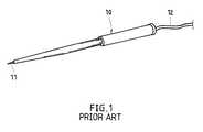
- FIG. 1illustrates a blood circulation stimulator according to the prior art.
- This structure of blood circulation stimulatorcomprises a pen-base body 10 , a discharge needle 11 extended out of the front end of the pen-base body 10 , and an electric cable 12 extended out of the rear end of the pen-base body 10 and connected to an AC adapter (not shown).
- the discharge needle 11When in use, the discharge needle 11 is pressed on an acupuncture point on the body of a person, enabling a low voltage electric current to be discharged into the acupuncture point to stimulate the circulation of blood.
- This structure of blood circulation stimulatoris not satisfactory in function. Because the blood circulation stimulator has only one discharge needle 11 , it can only stimulate one acupuncture point at a time.
- the discharge needle 11When in use, the discharge needle 11 must be accurately pressed on the selected acupuncture point. However, it is not easy to an ordinary people to accurately press the discharge needle 11 on the acupuncture point. Furthermore, this structure of blood circulation stimulator does not provide magnetic waves to stimulate blood circulation.
- the present inventionhas been accomplished under the circumstances in view. It is one object of the present invention to provide a blood circulation stimulator, which can easily be operated by an ordinary person without much learning. It is another object of the present invention to provide a blood circulation stimulator, which provides magnetic waves and a low voltage electric current to stimulate the circulation of blood of the person who receives the treatment.
- a blood circulation stimulatorcomprising a bottom cover shell, a top cover shell covered on the bottom cover shell and holding a battery set, a contact circuit board mounted inside the bottom cover shell to hold a plurality of spring-supported magnetic rod members and a plurality of electric current discharge rod members, and an electric current generator mounted in the top cover shell and controlled to output a low voltage electric current to the contact circuit board and then the electric current discharge rod members for stimulating the blood circulation of a person.
- the spring-supported magnetic rod members and the electric current discharge rod memberseach have a bottom end extending out of the bottom cover shell through a respective through hole on the bottom cover shell.
- FIG. 1is a blood circulation stimulator according to the prior art.
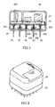
- FIG. 2is an exploded view of a blood circulation stimulator according to the present invention.
- FIG. 3is a sectional assembly view of the blood circulation stimulator shown in FIG. 2 .
- FIG. 4shows an application example of the present invention.
- FIG. 5is an elevational view of an alternate form of the blood circulation stimulator according to the present invention.
- a blood circulation stimulatoris shown comprised of a top cover shell 20 , an electric current generator 21 , a contact circuit board 22 , a plurality of magnetic rod members 23 , a plurality of electric discharge rod members 24 , and a bottom cover shell 25 .
- the top cover shell 20comprises a top battery chamber 201 , which holds a battery set (not shown), an elongated slot 202 , and a bottom-receiving chamber 203 , which receives the electric current generator 21 .
- the electric current generator 21is comprised of an electric current generating circuit assembly, a rotary current adjustment knob 210 , and conductors 211 and 212 respectively connected to the battery set in the top battery chamber 201 and the contact circuit board 22 .
- the contact circuit board 22comprises a plurality of through holes 220 , which receives the magnetic rod members 23 , a plurality of contact holes 221 , which receive the electric discharge rod members 24 , and a plurality of film conductors 222 connecting the contact holes 221 .
- the magnetic rod members 23each comprise a metal pin 230 , a cylindrical magnet 231 fixedly mounted on the metal pin 230 , and a spring 232 mounted on the metal pin 230 and supported above the cylindrical magnet 231 .
- the electric discharge rod members 24each comprise a collared metal pin 240 , and a spring 241 mounted on the metal pin 240 and supported above the collar on the metal pin 240 .
- the bottom cover shell 25fits the top cover shell 20 , comprising a plurality of through holes 250 corresponding to the through holes 220 and contact holes 221 on the contact circuit board 22 , an annular inside mounting flange 252 , and a plurality of fixed nuts 251 .
- the magnetic rod members 23 and the electric discharge rod members 24are respectively mounted in the bottom cover shell 25 , enabling the metal rods 230 and 240 of the magnetic rod members 23 and electric discharge rod members 24 to be respectively extended out of the bottom cover shell 25 through the through holes 250 , and then the circuit board 22 is supported on the annular inside mounting flange 252 inside the bottom cover shell 25 and fixedly fastened to the fixed nuts 251 by screws 223 , enabling the metal rods 230 and 240 of the magnetic rod members 23 and electric discharge rod members 24 to be respectively engaged into the through holes 220 and contact holes 221 on the circuit board 22 , and then the top cover shell 20 is covered on the bottom cover shell 25 to hold the electric current generator 21 on the inside, enabling the conductors 211 and 212 of the electric current generator 21 to be respectively connected to the battery set in the top battery chamber 201 and the contact circuit board 22 .
- the rotary current adjustment knob 210extends out
- the rotary current adjustment knob 210when in use, is operated to turn on the electric current generator 21 , causing it to output a low voltage electric current to the contact holes 221 and the electric current discharge rod members 24 .
- the acupuncture points A and B of the body 3When contacting the acupuncture points A and B of the body 3 with the metal rods 230 and 240 of the magnetic rod members 23 and electric discharge rod members 24 , the acupuncture points A and B of the body 3 are stimulated with magnetic waves and a low voltage electric current, and therefore the circulation of blood is stimulated. Because the rod members 23 and 24 are supported on the respective springs 232 and 241 , the blood circulation stimulator can be smoothly moved over the skin without hurting the body 3 . Further, the rotary current adjustment knob 210 can be controlled to provide selective current to the electric discharge rod members 24 .
- FIG. 5shows an alternate form of the blood circulation stimulator.
- the top cover shell 26 and the bottom cover shell 27have a square configuration.
Landscapes
- Health & Medical Sciences (AREA)
- Veterinary Medicine (AREA)
- Public Health (AREA)
- General Health & Medical Sciences (AREA)
- Animal Behavior & Ethology (AREA)
- Life Sciences & Earth Sciences (AREA)
- Rehabilitation Therapy (AREA)
- Engineering & Computer Science (AREA)
- Biomedical Technology (AREA)
- Nuclear Medicine, Radiotherapy & Molecular Imaging (AREA)
- Radiology & Medical Imaging (AREA)
- Physical Education & Sports Medicine (AREA)
- Pain & Pain Management (AREA)
- Epidemiology (AREA)
- Magnetic Treatment Devices (AREA)
Abstract
Description
The present invention relates to a blood circulation stimulator, and more particularly to such a blood circulation stimulator, which discharges magnetic waves and a low voltage electric current to stimulate the circulation of blood when touching the acupuncture points on the body of a person or moved over the body of the person
FIG. 1 illustrates a blood circulation stimulator according to the prior art. This structure of blood circulation stimulator comprises a pen-base body 10, adischarge needle 11 extended out of the front end of the pen-base body 10, and anelectric cable 12 extended out of the rear end of the pen-base body 10 and connected to an AC adapter (not shown). When in use, thedischarge needle 11 is pressed on an acupuncture point on the body of a person, enabling a low voltage electric current to be discharged into the acupuncture point to stimulate the circulation of blood. This structure of blood circulation stimulator is not satisfactory in function. Because the blood circulation stimulator has only onedischarge needle 11, it can only stimulate one acupuncture point at a time. When in use, thedischarge needle 11 must be accurately pressed on the selected acupuncture point. However, it is not easy to an ordinary people to accurately press thedischarge needle 11 on the acupuncture point. Furthermore, this structure of blood circulation stimulator does not provide magnetic waves to stimulate blood circulation.
The present invention has been accomplished under the circumstances in view. It is one object of the present invention to provide a blood circulation stimulator, which can easily be operated by an ordinary person without much learning. It is another object of the present invention to provide a blood circulation stimulator, which provides magnetic waves and a low voltage electric current to stimulate the circulation of blood of the person who receives the treatment. To achieve these and other objects of the present invention, there is provided a blood circulation stimulator comprising a bottom cover shell, a top cover shell covered on the bottom cover shell and holding a battery set, a contact circuit board mounted inside the bottom cover shell to hold a plurality of spring-supported magnetic rod members and a plurality of electric current discharge rod members, and an electric current generator mounted in the top cover shell and controlled to output a low voltage electric current to the contact circuit board and then the electric current discharge rod members for stimulating the blood circulation of a person. The spring-supported magnetic rod members and the electric current discharge rod members each have a bottom end extending out of the bottom cover shell through a respective through hole on the bottom cover shell.
FIG. 1 is a blood circulation stimulator according to the prior art.
FIG. 2 is an exploded view of a blood circulation stimulator according to the present invention.
FIG. 3 is a sectional assembly view of the blood circulation stimulator shown in FIG.2.
FIG. 4 shows an application example of the present invention.
FIG. 5 is an elevational view of an alternate form of the blood circulation stimulator according to the present invention.
Referring to FIGS. 2 and 3, a blood circulation stimulator is shown comprised of atop cover shell 20, anelectric current generator 21, acontact circuit board 22, a plurality ofmagnetic rod members 23, a plurality of electricdischarge rod members 24, and abottom cover shell 25.
Thetop cover shell 20 comprises atop battery chamber 201, which holds a battery set (not shown), anelongated slot 202, and a bottom-receiving chamber 203, which receives the electriccurrent generator 21. Theelectric current generator 21 is comprised of an electric current generating circuit assembly, a rotarycurrent adjustment knob 210, andconductors top battery chamber 201 and thecontact circuit board 22. Thecontact circuit board 22 comprises a plurality of throughholes 220, which receives themagnetic rod members 23, a plurality ofcontact holes 221, which receive the electricdischarge rod members 24, and a plurality offilm conductors 222 connecting thecontact holes 221. Themagnetic rod members 23 each comprise ametal pin 230, acylindrical magnet 231 fixedly mounted on themetal pin 230, and aspring 232 mounted on themetal pin 230 and supported above thecylindrical magnet 231. The electricdischarge rod members 24 each comprise acollared metal pin 240, and aspring 241 mounted on themetal pin 240 and supported above the collar on themetal pin 240. Thebottom cover shell 25 fits thetop cover shell 20, comprising a plurality of throughholes 250 corresponding to the throughholes 220 andcontact holes 221 on thecontact circuit board 22, an annularinside mounting flange 252, and a plurality offixed nuts 251.
The assembly process of the present invention is outlined hereinafter with reference to FIGS. 2 and 3 again, themagnetic rod members 23 and the electricdischarge rod members 24 are respectively mounted in thebottom cover shell 25, enabling themetal rods magnetic rod members 23 and electricdischarge rod members 24 to be respectively extended out of thebottom cover shell 25 through the throughholes 250, and then thecircuit board 22 is supported on the annularinside mounting flange 252 inside thebottom cover shell 25 and fixedly fastened to thefixed nuts 251 byscrews 223, enabling themetal rods magnetic rod members 23 and electricdischarge rod members 24 to be respectively engaged into the throughholes 220 andcontact holes 221 on thecircuit board 22, and then thetop cover shell 20 is covered on thebottom cover shell 25 to hold theelectric current generator 21 on the inside, enabling theconductors electric current generator 21 to be respectively connected to the battery set in thetop battery chamber 201 and thecontact circuit board 22. When assembled, the rotarycurrent adjustment knob 210 extends out of thetop cover shell 20 through theelongated slot 202, and thesprings respective rod members
Referring to FIG. 4, when in use, the rotarycurrent adjustment knob 210 is operated to turn on theelectric current generator 21, causing it to output a low voltage electric current to thecontact holes 221 and the electric currentdischarge rod members 24. When contacting the acupuncture points A and B of thebody 3 with themetal rods magnetic rod members 23 and electricdischarge rod members 24, the acupuncture points A and B of thebody 3 are stimulated with magnetic waves and a low voltage electric current, and therefore the circulation of blood is stimulated. Because therod members respective springs body 3. Further, the rotarycurrent adjustment knob 210 can be controlled to provide selective current to the electricdischarge rod members 24.
FIG. 5 shows an alternate form of the blood circulation stimulator. According to this embodiment, thetop cover shell 26 and thebottom cover shell 27 have a square configuration.
It is to be understood that the drawings are designed for purposes of illustration only, and are not intended for use as a definition of the limits and scope of the invention disclosed.
Claims (3)
1. A blood circulation stimulator comprising:
a bottom cover shell, said bottom cover shell comprising a plurality of through holes, a plurality of fixed nuts, and an annular inside mounting flange;
a top cover shell covered on said bottom cover shell, said top cover shell comprising a bottom receiving chamber, a top battery chamber, which receives a battery set, and an elongated slot;
a contact circuit board supported on said annular inside mounting flange inside said bottom cover shell and fixedly fastened to said fixed nuts with screws, said contact circuit board comprising a plurality of through holes, a plurality of contact holes, and a plurality of film conductors connecting said contact holes;
an electric current generator mounted in the bottom receiving chamber inside said top cover shell and connected between the battery set in said top battery chamber of said top cover shell and the contact holes of said contact circuit board with conductor means and controlled to output a low voltage electric current to said contact holes, said electric current generator comprising a rotary current control knob extended out of the elongated slot on said top cover shell for operation with the hand to control the output of said low voltage electric current to said contact holes;
a plurality of magnetic rod members respectively positioned in the through holes on said contact circuit board and the through holes on said bottom cover shell, said magnetic rod members each comprising a metal pin having a top end inserted into one through hole on said contact circuit board and a bottom end extending out of said bottom cover shell through one through hole on said bottom cover shell, a cylindrical magnet fixedly mounted on the respective metal pin, and a spring mounted on the metal pin of the respective magnetic rod member and supported between said cylindrical magnet and said contact circuit board; and
a plurality of electric discharge rod members respectively positioned in the through holes on said contact circuit board and the contact holes on said bottom cover shell for transmitting said low voltage electric current from said contact holes to a person's body to stimulate the person's blood circulation, said electric discharged rod members each comprising a metal pin having a top end disposed in contact with one contact hole on said contact circuit board and a bottom extending out of said bottom cover shell through one through hole on said bottom cover shell, and a spring supported between said contact circuit board and a part of the metal pin of the corresponding electric current discharge member.
2. The blood circulation stimulator ofclaim 1 wherein said top cover shell and said bottom cover shell have a circular configuration.
3. The blood circulation stimulator ofclaim 1 wherein said top cover shell and said bottom cover shell have a square configuration.
Priority Applications (2)
| Application Number | Priority Date | Filing Date | Title |
|---|---|---|---|
| US09/542,915US6338347B1 (en) | 2000-04-04 | 2000-04-04 | Blood circulation stimulator |
| DE20008328UDE20008328U1 (en) | 2000-04-04 | 2000-05-09 | Electronic healthcare device |
Applications Claiming Priority (2)
| Application Number | Priority Date | Filing Date | Title |
|---|---|---|---|
| US09/542,915US6338347B1 (en) | 2000-04-04 | 2000-04-04 | Blood circulation stimulator |
| DE20008328UDE20008328U1 (en) | 2000-04-04 | 2000-05-09 | Electronic healthcare device |
Publications (1)
| Publication Number | Publication Date |
|---|---|
| US6338347B1true US6338347B1 (en) | 2002-01-15 |
Family
ID=26056254
Family Applications (1)
| Application Number | Title | Priority Date | Filing Date |
|---|---|---|---|
| US09/542,915Expired - LifetimeUS6338347B1 (en) | 2000-04-04 | 2000-04-04 | Blood circulation stimulator |
Country Status (2)
| Country | Link |
|---|---|
| US (1) | US6338347B1 (en) |
| DE (1) | DE20008328U1 (en) |
Cited By (26)
| Publication number | Priority date | Publication date | Assignee | Title |
|---|---|---|---|---|
| US20040171914A1 (en)* | 2001-06-18 | 2004-09-02 | Dov Avni | In vivo sensing device with a circuit board having rigid sections and flexible sections |
| EP1462077A1 (en)* | 2003-03-26 | 2004-09-29 | Chen, Yi-Ying | An acupuncture electrode with multiple contact points and an acupuncture apparatus with multiple acupuncture electrodes |
| US20050171398A1 (en)* | 2002-12-26 | 2005-08-04 | Given Imaging Ltd. | In vivo imaging device and method of manufacture thereof |
| US20050182457A1 (en)* | 2004-02-12 | 2005-08-18 | Ndi Medical, Llc | Portable assemblies, systems and methods for providing functional or therapeutic neuromuscular stimulation |
| US20050182455A1 (en)* | 2004-02-12 | 2005-08-18 | Ndi Medical, Llc | Portable percutaneous assemblies, systems and methods for providing highly selective functional or therapeutic neuromuscular stimulation |
| US20050278000A1 (en)* | 2004-06-10 | 2005-12-15 | Strother Robert B | Implantable pulse generator for providing functional and/or therapeutic stimulation of muscles and/or nerves and/or central nervous system tissue |
| US20060004257A1 (en)* | 2004-06-30 | 2006-01-05 | Zvika Gilad | In vivo device with flexible circuit board and method for assembly thereof |
| US7020526B1 (en)* | 2002-05-16 | 2006-03-28 | Ruan Jin Zhao | Electronic gastro-intestinal stimulation device |
| US20060104057A1 (en)* | 2004-10-28 | 2006-05-18 | Jerome Avron | Device and method for in-vivo illumination |
| US20060122453A1 (en)* | 2004-12-02 | 2006-06-08 | Nikolay Alekseyenko | Therapeutic device for local area stimulation |
| US20060135844A1 (en)* | 2004-12-02 | 2006-06-22 | Nikolay Alekseyenko | Therapeutic device for local area stimulation |
| US20060241422A1 (en)* | 2005-03-31 | 2006-10-26 | Given Imaging Ltd. | Antenna for in-vivo imaging system |
| US20070060980A1 (en)* | 2004-06-10 | 2007-03-15 | Ndi Medical, Llc | Implantable pulse generator systems and methods for providing functional and/or therapeutic stimulation of muscles and/or nerves and/or central nervous system tissue |
| US20070060968A1 (en)* | 2004-06-10 | 2007-03-15 | Ndi Medical, Llc | Implantable pulse generator systems and methods for providing functional and/or therapeutic stimulation of muscles and/or nerves and/or central nervous system tissue |
| US20070118012A1 (en)* | 2005-11-23 | 2007-05-24 | Zvika Gilad | Method of assembling an in-vivo imaging device |
| US20070293910A1 (en)* | 2004-06-10 | 2007-12-20 | Ndi Medical, Inc. | Implantable pulse generator for providing functional and/or therapeutic stimulation of muscles and/or nerves and/or central nervous system tissue |
| US20080065182A1 (en)* | 2004-02-12 | 2008-03-13 | Ndi Medical, Llc. | Portable assemblies, systems, and methods for providing functional or therapeutic neurostimulation |
| US20100036445A1 (en)* | 2008-08-01 | 2010-02-11 | Ndi Medical Llc. | Portable assemblies, systems, and methods for providing functional or therapeutic neurostimulation |
| US7761167B2 (en) | 2004-06-10 | 2010-07-20 | Medtronic Urinary Solutions, Inc. | Systems and methods for clinician control of stimulation systems |
| US20100295148A1 (en)* | 2007-01-11 | 2010-11-25 | Micron Technology, Inc. | Methods of uniformly removing silicon oxide and an intermediate semiconductor device |
| US20100326703A1 (en)* | 2009-06-24 | 2010-12-30 | Zvika Gilad | In vivo sensing device with a flexible circuit board and method of assembly thereof |
| US8195304B2 (en) | 2004-06-10 | 2012-06-05 | Medtronic Urinary Solutions, Inc. | Implantable systems and methods for acquisition and processing of electrical signals |
| US8467875B2 (en) | 2004-02-12 | 2013-06-18 | Medtronic, Inc. | Stimulation of dorsal genital nerves to treat urologic dysfunctions |
| US9480846B2 (en) | 2006-05-17 | 2016-11-01 | Medtronic Urinary Solutions, Inc. | Systems and methods for patient control of stimulation systems |
| US10032593B1 (en)* | 2017-05-18 | 2018-07-24 | Groon Co., Ltd. | Electron generation apparatus |
| US20240157129A1 (en)* | 2020-08-06 | 2024-05-16 | G.M Corporation Co., Ltd. | Skin stimulation brush |
Families Citing this family (1)
| Publication number | Priority date | Publication date | Assignee | Title |
|---|---|---|---|---|
| US6735480B2 (en)* | 2001-06-29 | 2004-05-11 | Abbott Laboratories | Electro-acupuncture device with D-shaped stimulation electrodes |
Citations (7)
| Publication number | Priority date | Publication date | Assignee | Title |
|---|---|---|---|---|
| US4262672A (en)* | 1978-01-02 | 1981-04-21 | Horst Kief | Acupuncture instrument |
| US4763657A (en)* | 1987-04-06 | 1988-08-16 | Chen Chen Wei | Thermally-treated electronic acupuncturer |
| US4915110A (en)* | 1986-08-21 | 1990-04-10 | Theri-Teck, Inc. | Therapeutic electrostatic device |
| US5012816A (en)* | 1989-08-31 | 1991-05-07 | Gabor Lederer | Electronic acupuncture device |
| US5030196A (en)* | 1980-04-23 | 1991-07-09 | Inoue-Japax Research Incorporated | Magnetic treatment device |
| US5385150A (en)* | 1989-04-05 | 1995-01-31 | Ishikawa; Keihachi | Acupuncture device |
| US5607461A (en)* | 1995-10-20 | 1997-03-04 | Nexmed, Inc. | Apparatus and method for delivering electrical stimulus to tissue |
- 2000
- 2000-04-04USUS09/542,915patent/US6338347B1/ennot_activeExpired - Lifetime
- 2000-05-09DEDE20008328Upatent/DE20008328U1/ennot_activeExpired - Lifetime
Patent Citations (7)
| Publication number | Priority date | Publication date | Assignee | Title |
|---|---|---|---|---|
| US4262672A (en)* | 1978-01-02 | 1981-04-21 | Horst Kief | Acupuncture instrument |
| US5030196A (en)* | 1980-04-23 | 1991-07-09 | Inoue-Japax Research Incorporated | Magnetic treatment device |
| US4915110A (en)* | 1986-08-21 | 1990-04-10 | Theri-Teck, Inc. | Therapeutic electrostatic device |
| US4763657A (en)* | 1987-04-06 | 1988-08-16 | Chen Chen Wei | Thermally-treated electronic acupuncturer |
| US5385150A (en)* | 1989-04-05 | 1995-01-31 | Ishikawa; Keihachi | Acupuncture device |
| US5012816A (en)* | 1989-08-31 | 1991-05-07 | Gabor Lederer | Electronic acupuncture device |
| US5607461A (en)* | 1995-10-20 | 1997-03-04 | Nexmed, Inc. | Apparatus and method for delivering electrical stimulus to tissue |
Cited By (56)
| Publication number | Priority date | Publication date | Assignee | Title |
|---|---|---|---|---|
| US20040171914A1 (en)* | 2001-06-18 | 2004-09-02 | Dov Avni | In vivo sensing device with a circuit board having rigid sections and flexible sections |
| US7998065B2 (en)* | 2001-06-18 | 2011-08-16 | Given Imaging Ltd. | In vivo sensing device with a circuit board having rigid sections and flexible sections |
| US7020526B1 (en)* | 2002-05-16 | 2006-03-28 | Ruan Jin Zhao | Electronic gastro-intestinal stimulation device |
| US20050171398A1 (en)* | 2002-12-26 | 2005-08-04 | Given Imaging Ltd. | In vivo imaging device and method of manufacture thereof |
| US7833151B2 (en) | 2002-12-26 | 2010-11-16 | Given Imaging Ltd. | In vivo imaging device with two imagers |
| EP1462077A1 (en)* | 2003-03-26 | 2004-09-29 | Chen, Yi-Ying | An acupuncture electrode with multiple contact points and an acupuncture apparatus with multiple acupuncture electrodes |
| US20050182455A1 (en)* | 2004-02-12 | 2005-08-18 | Ndi Medical, Llc | Portable percutaneous assemblies, systems and methods for providing highly selective functional or therapeutic neuromuscular stimulation |
| WO2005081740A3 (en)* | 2004-02-12 | 2006-03-09 | Ndi Medical Llc | Portable percutaneous assemblies providing therapeutic neuromuscular stimulation |
| US8086318B2 (en) | 2004-02-12 | 2011-12-27 | Ndi Medical, Llc | Portable assemblies, systems, and methods for providing functional or therapeutic neurostimulation |
| US8467875B2 (en) | 2004-02-12 | 2013-06-18 | Medtronic, Inc. | Stimulation of dorsal genital nerves to treat urologic dysfunctions |
| US20080065182A1 (en)* | 2004-02-12 | 2008-03-13 | Ndi Medical, Llc. | Portable assemblies, systems, and methods for providing functional or therapeutic neurostimulation |
| US20050182457A1 (en)* | 2004-02-12 | 2005-08-18 | Ndi Medical, Llc | Portable assemblies, systems and methods for providing functional or therapeutic neuromuscular stimulation |
| US7120499B2 (en)* | 2004-02-12 | 2006-10-10 | Ndi Medical, Llc | Portable percutaneous assemblies, systems and methods for providing highly selective functional or therapeutic neuromuscular stimulation |
| US20100100158A1 (en)* | 2004-02-12 | 2010-04-22 | Ndi Medical, Llc | Percutaneous electrode assemblies, systems, and methods for providing highly selective functional or therapeutic neuromuscular stimulation |
| US20070032836A1 (en)* | 2004-02-12 | 2007-02-08 | Ndi Medical, Llc | Percutaneous electrode assemblies, systems, and methods for providing highly selective functional or therapeutic neuromuscular stimulation |
| US20070032837A1 (en)* | 2004-02-12 | 2007-02-08 | Ndi Medical, Llc | Portable percutaneous assemblies, systems and methods for providing highly selective functional or therapeutic neuromuscular stimulation |
| US7571002B2 (en)* | 2004-02-12 | 2009-08-04 | Ndi Medical, Llc | Portable percutaneous assemblies, systems and methods for providing highly selective functional or therapeutic neuromuscular stimulation |
| US7376467B2 (en) | 2004-02-12 | 2008-05-20 | Ndi Medical, Inc. | Portable assemblies, systems and methods for providing functional or therapeutic neuromuscular stimulation |
| US20100274324A1 (en)* | 2004-06-10 | 2010-10-28 | Medtronic Urinary Solutions, Inc. | Systems and methods for clinician control of stimulation system |
| US8195304B2 (en) | 2004-06-10 | 2012-06-05 | Medtronic Urinary Solutions, Inc. | Implantable systems and methods for acquisition and processing of electrical signals |
| US10434320B2 (en) | 2004-06-10 | 2019-10-08 | Medtronic Urinary Solutions, Inc. | Implantable pulse generator systems and methods for providing functional and/or therapeutic stimulation of muscles and/or nerves and/or central nervous system tissue |
| US20070060968A1 (en)* | 2004-06-10 | 2007-03-15 | Ndi Medical, Llc | Implantable pulse generator systems and methods for providing functional and/or therapeutic stimulation of muscles and/or nerves and/or central nervous system tissue |
| US10293168B2 (en) | 2004-06-10 | 2019-05-21 | Medtronic Urinary Solutions, Inc. | Systems and methods for clinician control of stimulation systems |
| US20070060980A1 (en)* | 2004-06-10 | 2007-03-15 | Ndi Medical, Llc | Implantable pulse generator systems and methods for providing functional and/or therapeutic stimulation of muscles and/or nerves and/or central nervous system tissue |
| US9724526B2 (en) | 2004-06-10 | 2017-08-08 | Medtronic Urinary Solutions, Inc. | Implantable pulse generator systems and methods for operating the same |
| US9308382B2 (en) | 2004-06-10 | 2016-04-12 | Medtronic Urinary Solutions, Inc. | Implantable pulse generator systems and methods for providing functional and/or therapeutic stimulation of muscles and/or nerves and/or central nervous system tissue |
| US7761167B2 (en) | 2004-06-10 | 2010-07-20 | Medtronic Urinary Solutions, Inc. | Systems and methods for clinician control of stimulation systems |
| US9216294B2 (en) | 2004-06-10 | 2015-12-22 | Medtronic Urinary Solutions, Inc. | Systems and methods for clinician control of stimulation systems |
| US7813809B2 (en) | 2004-06-10 | 2010-10-12 | Medtronic, Inc. | Implantable pulse generator for providing functional and/or therapeutic stimulation of muscles and/or nerves and/or central nervous system tissue |
| US9205255B2 (en) | 2004-06-10 | 2015-12-08 | Medtronic Urinary Solutions, Inc. | Implantable pulse generator systems and methods for providing functional and/or therapeutic stimulation of muscles and/or nerves and/or central nervous system tissue |
| US8706252B2 (en) | 2004-06-10 | 2014-04-22 | Medtronic, Inc. | Systems and methods for clinician control of stimulation system |
| US20050278000A1 (en)* | 2004-06-10 | 2005-12-15 | Strother Robert B | Implantable pulse generator for providing functional and/or therapeutic stimulation of muscles and/or nerves and/or central nervous system tissue |
| US20070293910A1 (en)* | 2004-06-10 | 2007-12-20 | Ndi Medical, Inc. | Implantable pulse generator for providing functional and/or therapeutic stimulation of muscles and/or nerves and/or central nervous system tissue |
| US8165692B2 (en) | 2004-06-10 | 2012-04-24 | Medtronic Urinary Solutions, Inc. | Implantable pulse generator power management |
| US20060004257A1 (en)* | 2004-06-30 | 2006-01-05 | Zvika Gilad | In vivo device with flexible circuit board and method for assembly thereof |
| US8500630B2 (en) | 2004-06-30 | 2013-08-06 | Given Imaging Ltd. | In vivo device with flexible circuit board and method for assembly thereof |
| US20060104057A1 (en)* | 2004-10-28 | 2006-05-18 | Jerome Avron | Device and method for in-vivo illumination |
| US20060122453A1 (en)* | 2004-12-02 | 2006-06-08 | Nikolay Alekseyenko | Therapeutic device for local area stimulation |
| US20060135844A1 (en)* | 2004-12-02 | 2006-06-22 | Nikolay Alekseyenko | Therapeutic device for local area stimulation |
| US8075470B2 (en)* | 2004-12-02 | 2011-12-13 | Nikolay Alekseyenko | Therapeutic device for local area stimulation |
| US20080207984A1 (en)* | 2004-12-02 | 2008-08-28 | Nikolay Alekseyenko | Therapeutic device for local area stimulation |
| US20060241422A1 (en)* | 2005-03-31 | 2006-10-26 | Given Imaging Ltd. | Antenna for in-vivo imaging system |
| US7801586B2 (en) | 2005-03-31 | 2010-09-21 | Given Imaging Ltd. | Antenna for in-vivo imaging system |
| US20070118012A1 (en)* | 2005-11-23 | 2007-05-24 | Zvika Gilad | Method of assembling an in-vivo imaging device |
| US10322287B2 (en) | 2006-05-17 | 2019-06-18 | Medtronic Urinary Solutions, Inc. | Systems and methods for patient control of stimulation systems |
| US9480846B2 (en) | 2006-05-17 | 2016-11-01 | Medtronic Urinary Solutions, Inc. | Systems and methods for patient control of stimulation systems |
| US20100295148A1 (en)* | 2007-01-11 | 2010-11-25 | Micron Technology, Inc. | Methods of uniformly removing silicon oxide and an intermediate semiconductor device |
| US8435904B2 (en)* | 2007-01-11 | 2013-05-07 | Micron Technology, Inc. | Methods of uniformly removing silicon oxide and an intermediate semiconductor device |
| US20100036445A1 (en)* | 2008-08-01 | 2010-02-11 | Ndi Medical Llc. | Portable assemblies, systems, and methods for providing functional or therapeutic neurostimulation |
| US8463383B2 (en) | 2008-08-01 | 2013-06-11 | Ndi Medical, Inc. | Portable assemblies, systems, and methods for providing functional or therapeutic neurostimulation |
| US9078579B2 (en) | 2009-06-24 | 2015-07-14 | Given Imaging Ltd. | In vivo sensing device with a flexible circuit board |
| US8516691B2 (en) | 2009-06-24 | 2013-08-27 | Given Imaging Ltd. | Method of assembly of an in vivo imaging device with a flexible circuit board |
| US20100326703A1 (en)* | 2009-06-24 | 2010-12-30 | Zvika Gilad | In vivo sensing device with a flexible circuit board and method of assembly thereof |
| US10032593B1 (en)* | 2017-05-18 | 2018-07-24 | Groon Co., Ltd. | Electron generation apparatus |
| US20240157129A1 (en)* | 2020-08-06 | 2024-05-16 | G.M Corporation Co., Ltd. | Skin stimulation brush |
| US12383734B2 (en)* | 2020-08-06 | 2025-08-12 | G.M Corporation Co., Ltd. | Skin stimulation brush |
Also Published As
| Publication number | Publication date |
|---|---|
| DE20008328U1 (en) | 2000-10-19 |
Similar Documents
| Publication | Publication Date | Title |
|---|---|---|
| US6338347B1 (en) | Blood circulation stimulator | |
| US9042993B2 (en) | Skin-hair treatment method and system | |
| EP3741426A1 (en) | Nerve stimulator | |
| WO2002026313A3 (en) | Method and apparatus employing a scaling exponent for selectively defibrillating a patient | |
| US9119967B2 (en) | Systems and methods for reducing electromagnetic field-induced heating from an implantable pulse generator | |
| JPS6485669A (en) | Electrostatic device for medical treatment and non- penetrating contact electronic device | |
| AU5409590A (en) | Acupuncture locating device | |
| EP2119472B1 (en) | Skin/hair treatment system | |
| US20160310734A1 (en) | Handheld electrical stimulation medical device | |
| US4532938A (en) | Electrotherapy apparatus | |
| KR101829015B1 (en) | A Massage Type of a Health Device Having a Structure of Applying a Micro Current | |
| US6415177B1 (en) | Transcutaneous electrical nerve stimulator | |
| US6185462B1 (en) | Apparatus for electrically treating skin disorders | |
| JPH0432115Y2 (en) | ||
| JP3218941U (en) | Earbud pressing fixture | |
| CN110801390A (en) | Lattice arrangement type beauty instrument | |
| KR200453125Y1 (en) | Portable potential generator | |
| JP3102861U (en) | Low frequency treatment device | |
| KR200317889Y1 (en) | Glove for generating low frequency wave | |
| KR20250043816A (en) | Electrode assembly with spring contact structure | |
| RU1783983C (en) | Appliance for electroreflexotherapy | |
| US372808A (en) | Feedeeick j | |
| JP2006087759A (en) | Low frequency therapy apparatus | |
| ATE226810T1 (en) | PIEZOELECTRIC STIMULATION HANDHELD DEVICE FOR ACUPUNCTURE | |
| CN1109369A (en) | Electric, magnetic and infrared therapeutic pen |
Legal Events
| Date | Code | Title | Description |
|---|---|---|---|
| STCF | Information on status: patent grant | Free format text:PATENTED CASE | |
| FPAY | Fee payment | Year of fee payment:4 | |
| REMI | Maintenance fee reminder mailed | ||
| FPAY | Fee payment | Year of fee payment:8 | |
| SULP | Surcharge for late payment | Year of fee payment:7 | |
| REMI | Maintenance fee reminder mailed | ||
| FPAY | Fee payment | Year of fee payment:12 | |
| SULP | Surcharge for late payment | Year of fee payment:11 |