US6336986B1 - Method for producing hybrid driveshaft - Google Patents
Method for producing hybrid driveshaftDownload PDFInfo
- Publication number
- US6336986B1 US6336986B1US09/104,109US10410998AUS6336986B1US 6336986 B1US6336986 B1US 6336986B1US 10410998 AUS10410998 AUS 10410998AUS 6336986 B1US6336986 B1US 6336986B1
- Authority
- US
- United States
- Prior art keywords
- metal tube
- composite material
- material layer
- tube
- hybrid
- Prior art date
- Legal status (The legal status is an assumption and is not a legal conclusion. Google has not performed a legal analysis and makes no representation as to the accuracy of the status listed.)
- Expired - Fee Related
Links
Images


Classifications
- F—MECHANICAL ENGINEERING; LIGHTING; HEATING; WEAPONS; BLASTING
- F16—ENGINEERING ELEMENTS AND UNITS; GENERAL MEASURES FOR PRODUCING AND MAINTAINING EFFECTIVE FUNCTIONING OF MACHINES OR INSTALLATIONS; THERMAL INSULATION IN GENERAL
- F16C—SHAFTS; FLEXIBLE SHAFTS; ELEMENTS OR CRANKSHAFT MECHANISMS; ROTARY BODIES OTHER THAN GEARING ELEMENTS; BEARINGS
- F16C3/00—Shafts; Axles; Cranks; Eccentrics
- F16C3/02—Shafts; Axles
- F16C3/026—Shafts made of fibre reinforced resin
- B—PERFORMING OPERATIONS; TRANSPORTING
- B29—WORKING OF PLASTICS; WORKING OF SUBSTANCES IN A PLASTIC STATE IN GENERAL
- B29C—SHAPING OR JOINING OF PLASTICS; SHAPING OF MATERIAL IN A PLASTIC STATE, NOT OTHERWISE PROVIDED FOR; AFTER-TREATMENT OF THE SHAPED PRODUCTS, e.g. REPAIRING
- B29C70/00—Shaping composites, i.e. plastics material comprising reinforcements, fillers or preformed parts, e.g. inserts
- B29C70/04—Shaping composites, i.e. plastics material comprising reinforcements, fillers or preformed parts, e.g. inserts comprising reinforcements only, e.g. self-reinforcing plastics
- B29C70/06—Fibrous reinforcements only
- B29C70/08—Fibrous reinforcements only comprising combinations of different forms of fibrous reinforcements incorporated in matrix material, forming one or more layers, and with or without non-reinforced layers
- B29C70/088—Fibrous reinforcements only comprising combinations of different forms of fibrous reinforcements incorporated in matrix material, forming one or more layers, and with or without non-reinforced layers and with one or more layers of non-plastics material or non-specified material, e.g. supports
- B—PERFORMING OPERATIONS; TRANSPORTING
- B29—WORKING OF PLASTICS; WORKING OF SUBSTANCES IN A PLASTIC STATE IN GENERAL
- B29C—SHAPING OR JOINING OF PLASTICS; SHAPING OF MATERIAL IN A PLASTIC STATE, NOT OTHERWISE PROVIDED FOR; AFTER-TREATMENT OF THE SHAPED PRODUCTS, e.g. REPAIRING
- B29C70/00—Shaping composites, i.e. plastics material comprising reinforcements, fillers or preformed parts, e.g. inserts
- B29C70/88—Shaping composites, i.e. plastics material comprising reinforcements, fillers or preformed parts, e.g. inserts characterised primarily by possessing specific properties, e.g. electrically conductive or locally reinforced
- B29C70/882—Shaping composites, i.e. plastics material comprising reinforcements, fillers or preformed parts, e.g. inserts characterised primarily by possessing specific properties, e.g. electrically conductive or locally reinforced partly or totally electrically conductive, e.g. for EMI shielding
- B29C70/885—Shaping composites, i.e. plastics material comprising reinforcements, fillers or preformed parts, e.g. inserts characterised primarily by possessing specific properties, e.g. electrically conductive or locally reinforced partly or totally electrically conductive, e.g. for EMI shielding with incorporated metallic wires, nets, films or plates
- B—PERFORMING OPERATIONS; TRANSPORTING
- B29—WORKING OF PLASTICS; WORKING OF SUBSTANCES IN A PLASTIC STATE IN GENERAL
- B29C—SHAPING OR JOINING OF PLASTICS; SHAPING OF MATERIAL IN A PLASTIC STATE, NOT OTHERWISE PROVIDED FOR; AFTER-TREATMENT OF THE SHAPED PRODUCTS, e.g. REPAIRING
- B29C61/00—Shaping by liberation of internal stresses; Making preforms having internal stresses; Apparatus therefor
- B29C61/006—Shaping by liberation of internal stresses; Making preforms having internal stresses; Apparatus therefor the force created by the liberation of the internal stresses being used for compression moulding or for pressing preformed material
- B—PERFORMING OPERATIONS; TRANSPORTING
- B29—WORKING OF PLASTICS; WORKING OF SUBSTANCES IN A PLASTIC STATE IN GENERAL
- B29L—INDEXING SCHEME ASSOCIATED WITH SUBCLASS B29C, RELATING TO PARTICULAR ARTICLES
- B29L2031/00—Other particular articles
- B29L2031/748—Machines or parts thereof not otherwise provided for
- B29L2031/75—Shafts
- Y—GENERAL TAGGING OF NEW TECHNOLOGICAL DEVELOPMENTS; GENERAL TAGGING OF CROSS-SECTIONAL TECHNOLOGIES SPANNING OVER SEVERAL SECTIONS OF THE IPC; TECHNICAL SUBJECTS COVERED BY FORMER USPC CROSS-REFERENCE ART COLLECTIONS [XRACs] AND DIGESTS
- Y10—TECHNICAL SUBJECTS COVERED BY FORMER USPC
- Y10S—TECHNICAL SUBJECTS COVERED BY FORMER USPC CROSS-REFERENCE ART COLLECTIONS [XRACs] AND DIGESTS
- Y10S464/00—Rotary shafts, gudgeons, housings, and flexible couplings for rotary shafts
- Y10S464/902—Particular material
- Y10S464/903—Nonmetal
Definitions
- This inventionrelates to a driveshaft of an automobile, more particularly to a hybrid driveshaft having a stem simply formed in one piece while the stem transmits a required driving torque and has high fundamental natural bending frequency to avoid a resonant critical vibration.
- This inventionalso relates to a method for producing the hybrid driveshaft.
- the driveshaft so called propeller shaftis used to transmit a driving torque from a transmission to a differential gear in an automobile.
- the driveshaftIn a rear wheel driving car or a four-wheel driving car, the driveshaft is as long as 1.5 ⁇ 2.0 m.
- the driveshaftis designed to withstand several thousand Nm, the driveshaft may be broken when it is subject to a resonant critical vibration at speed of revolution corresponding to its fundamental bending natural frequency. In order to avoid such a catastrophic fracture, the fundamental bending natural frequency of the driveshaft has to be more than 6,500 rpm.
- the fundamental bending natural frequency of the driveshaft with universal joints at both endsis in proportion to a square root of its specific modulus (E/ ⁇ ), and is in inverse proportion to a square of its length.
- E/ ⁇specific modulus
- a value of the specific modulusmust be increased, or the length of the driveshaft has to be shortened.
- a conventional steel driveshaftis often produced in two pieces. Since the steel driveshaft needs an additional universal joint to connect between two pieces, it is sophisticated to produce and assemble the driveshaft.
- a carbon-fiber-reinforced polymer composite material(hereinafter, called as “composite material”) has specific modulus more than four times of that of steel or aluminum.
- the driveshaft having the length reached to 1.5 ⁇ 2.0 mcan be reduced in a unitary member with the fundamental bending natural frequency of more than 6500 rpm using the composite material.
- this inventionis to propose a hybrid drive shaft in which a good torque transmission capability of metal and a high specific modulus of a composite material are well combined.
- a hybrid driveshaft of an automobilecomprises a unitary cylindrical hybrid stem including a metal tube having high strength and a composite material layer having high specific modulus. Joints associated with a transmission and a differential gear are formed at both ends of the stem.
- the metal tube and the composite material layerare adhered to each other by co-curing under a high pressurized atmosphere, thereby, the metal tube and the composite material layer cooperate with each other to provide a good torque transmission capability and a high fundamental bending natural frequency of the driveshaft.
- co-curingmeans that there are simultaneously occurred several processes, that is, heating metal and composite material, lowering the viscosity of the resin of the composite material, and adhering the metal and the composite material by the resin.
- a method for producing a hybrid driveshaft of an automobilecomprising a unitary cylindrical hybrid stem including a metal tube having high strength and a composite material layer having high specific modulus.
- the methodcomprises steps for forming joints at both ends of a metal tube, exerting an axial compressive force on the both ends of the metal tube to prevent it from being thermally expanded, stacking composite material on the metal tube, and co-curing the composite material by heating under high pressurized atmosphere so that the metal tube and the composite material are tightly adhered to each other.
- the metal tubemay be an aluminum alloy tube
- the composite materialmay be a unidirectional carbon fiber epoxy composite material.
- the jointsmay comprise two yoke members, one of which is associated with a corresponding yoke formed in a transmission, and the other of which is associated with a corresponding yoke formed in a differential gear of an automobile.
- the axial compressive forcemay be exerted by a device comprising a fixed flange confronted with one end of the metal tube, a moving flange confronted with the other end of the metal tube, and a nut cooperating with a screw to force the moving flange toward the metal tube so that the metal tube is compressed between the fixed flange and the moving flange. It is preferred to accomplish mechanical and chemical roughness treatment on an outside surface of the metal tube before the stacking step of the composite material.
- FIG. 1shows a plan view of an embodiment of the hybrid driveshaft according to the invention with the stem shown in longitudinal section,
- FIG. 2shows a cross sectional view of the stem shown in FIG. 1,
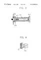
- FIG. 3shows a longitudinal section of an aluminum alloy tube compressed by a device during forming a unitary cylindrical hybrid stem
- FIG. 4shows a plan view of a yoke formed each end of the hybrid driveshaft shown in FIG. 1,
- FIG. 5shows a plan view of an inner serration ring to be engaged with the yoke shown in FIG. 4,
- FIG. 6shows a side view of the inner serration ring shown in FIG. 5,
- FIG. 7shows a partial view of the aluminum alloy tube with the inner serration ring shown in FIG. 5 inserted and welded at each end thereof,
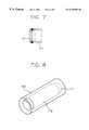
- FIG. 8shows a perspective view of a thermal shrinkage tube surrounding an aluminum alloy tube and composite material
- FIG. 9shows a partial view of the aluminum alloy tube with a stepless inner serration ring shrink-fitted by being forced in heated state
- FIG. 10shows a partial view of the aluminum alloy tube with a compression ring shrink-fitted around a position of the tube corresponding the position of the inner serration ring
- FIG. 11shows a partial view of the aluminum alloy tube with welding portion of the inner serration ring reinforced by several indentation welding portions.
- the hybrid driveshaftaccording to an embodiment of the invention comprises a stem 110 including a metal tube 111 having high strength and a composite material layer 112 formed from a unidirectional carbon fiber and epoxy resin.
- Two yokes 114 and 115are formed at ends of the stem 110 so that one of them is connected to a corresponding yoke in a transmission, and the other of them is connected to a corresponding yoke in a differential gear.
- the hybrid driveshaft 100has high torque transmission capability and a high fundamental bending natural frequency, which are induced from a high strength of the aluminum alloy and a high specific modulus of the composite material.
- the composite material layer 112is tightly adhered to the aluminum alloy layer 111 by co-curing under a high-pressurized atmosphere.
- a coating layer 113may be formed on the composite material layer 112 using a thermal shrinkage tube made of polyethylene resin or polypropylene resin.
- the composite materialshould be tightly adhered to the aluminum alloy while they have so different mechanical property with each other.
- the curing processcauses thermal residual stresses between the aluminum alloy tube and the composite material since there is great difference between the coefficient of thermal expansion in the composite material, ⁇ 0.9/, and that in the aluminum alloy, 23/.
- the problemis more serious in the longitudinal direction of the fiber of the composite material, that is, in the axial direction of the stem. Accordingly, it is noticed that the aluminum alloy tube should be subjected to axial compression by the amount of thermal expansion difference to prevent the aluminum alloy tube from being thermally expanded.
- the axial compressionmay be accomplished using a device 200 shown in FIG. 3 .
- the device 200comprises a moving flange 212 , a fixed flange and a nut 214 having handling rods.
- the aluminum alloy tube 111is placed between the moving flange 212 and the fixed flange 213 .
- the nut 214is rotated to move along with a screw while forcing the moving flange 212 to compress the aluminum alloy tube 111 .
- a thrust bearing 216is placed between the nut 214 and the moving flange 212 to prevent torsion moment by rotation of the nut 214 from being transferred to the aluminum alloy tube 111 .
- the composite material layer 112is formed as follows. Fiber-reinforced composite material is stacked on the outer surface of the aluminum alloy tube 111 . A pressure tape made of polymer such as polypropylene or polyethylene is winded around the composite material.
- the aluminum tube 111 with the composite material layer 112 stackedis surrounded by a vacuum bag made from a nylon film endurable under high temperature.
- a vacuum bagmade from a nylon film endurable under high temperature.
- Such an assemblyis heated in an autoclave under pressurized atmosphere while maintaining the vacuum state in the vacuum bag using a vacuum pump so that the composite material layer 112 is co-cured.
- a mechanical elementsuch as a universal joint is connected by welding to the aluminum alloy layer 111 with the composite material layer 112 cured, the carbon fiber epoxy composite is deteriorated by high temperature, and thereby the strength and the specific modulus of the hybrid stem are decreased.
- an adaptive mechanical elementsuch as a serration portion because the steel yoke can not be welded to the aluminum alloy tube 111 .
- FIGS. 5 and 6show a plan view and a side view of an inner serration ring 116 to be fitted into the stem 110 , respectively.
- the inner serration ring 116is fitted into the aluminum alloy tube 111 and welded before the composite material is stacked and co-cured.
- the steel yoke shown in FIG. 4is fitted into the inner serration ring 116 so that an inner serration 117 of the ring 116 is associated with an outer serration 121 of the steel yoke 114 . It is preferred to apply an adhesive into clearance between the both serrations 117 and 121 so that the steel yoke 114 can not get away from the stem 110 .
- a thermal shrinkage tube 130is fitted over the composite material layer 112 as shown in FIG. 8 in which the diameter of the thermal shrinkage tube 130 is slightly larger than that of the composite material layer 112 .
- the thermal shrinkage tube 130is heated by a heating gun or in an autoclave, the thermal shrinkage tube 130 is contracted to eliminate voids and volatile in the composite material, which deteriorates the quality of composite structure. Since contraction force of the thermal shrinkage tube 130 is sufficient to exert pressure for promoting consolidation of the composite material, an additive pressurization atmosphere is not required.
- a polyethylene thermal shrinkage tubeis preferred for the composite material cured at 120
- a polypropylene thermal shrinkage tubeis preferred for the composite material cured at 180 .
- the hybrid stem produced by this methodis not required any additive process for the water resistant, the chemical resistant and the insulated, since the thermal shrinkage tube 130 is acted as water resistant, chemical resistant and insulated coating.
- FIG. 9shows an inner serration ring 118 shrink-fitted into the aluminum alloy tube 111 in heated state.
- a stepless serration ring 118is used in instead of a stepped serration ring 116 shown in FIGS. 5 and 6.
- a compression ring 119is additionally shrink-fitted around a position of the aluminum alloy tube 111 corresponding to the position of the inner serration ring 118 to reinforce connection between the inner serration ring 118 and the aluminum alloy tube 111 .
- FIG. 11shows a partial view of the aluminum alloy tube with welding portion of the inner serration ring reinforced by several indentation welding portions.
- plug weldingmay be conducted by drilling several points of the aluminum tube and filling drilled holes with melt. It is preferred to conduct fillet welding after forming indentations 126 at the end of the tube 125 to be welded as shown in FIG. 11 .
Landscapes
- Engineering & Computer Science (AREA)
- Mechanical Engineering (AREA)
- General Engineering & Computer Science (AREA)
- Chemical & Material Sciences (AREA)
- Composite Materials (AREA)
- Ocean & Marine Engineering (AREA)
- Shafts, Cranks, Connecting Bars, And Related Bearings (AREA)
- Motor Power Transmission Devices (AREA)
Abstract
Description
Claims (15)
Applications Claiming Priority (4)
| Application Number | Priority Date | Filing Date | Title |
|---|---|---|---|
| KR1019970032643AKR100241851B1 (en) | 1997-07-14 | 1997-07-14 | Automotive power transmission shaft |
| KR97-32643 | 1997-07-14 | ||
| KR1019970047553AKR100241232B1 (en) | 1997-09-18 | 1997-09-18 | Composite shaft with thermal shrinkage tube and method producing it |
| KR97-47553 | 1997-09-18 |
Publications (1)
| Publication Number | Publication Date |
|---|---|
| US6336986B1true US6336986B1 (en) | 2002-01-08 |
Family
ID=26632927
Family Applications (1)
| Application Number | Title | Priority Date | Filing Date |
|---|---|---|---|
| US09/104,109Expired - Fee RelatedUS6336986B1 (en) | 1997-07-14 | 1998-06-25 | Method for producing hybrid driveshaft |
Country Status (1)
| Country | Link |
|---|---|
| US (1) | US6336986B1 (en) |
Cited By (23)
| Publication number | Priority date | Publication date | Assignee | Title |
|---|---|---|---|---|
| US20020166239A1 (en)* | 1999-04-16 | 2002-11-14 | Wolfgang Weissert | Motor driven implement |
| US20020195291A1 (en)* | 2001-06-21 | 2002-12-26 | Yasunori Nonogaki | Yoke, power transmission shaft, and method for manufacturing yoke |
| WO2003089145A3 (en)* | 2002-04-19 | 2004-08-05 | Bell Helicopter Textron Inc | Composite drive shaft with captured end adapters |
| US6863763B2 (en) | 2002-10-23 | 2005-03-08 | Korea Advanced Institute Of Science And Technology | Hybrid propeller shaft made of metal and composite material and method of manufacturing the same |
| US20060292019A1 (en)* | 2002-10-15 | 2006-12-28 | Bode Ralf H | Compressor unit |
| US20070006445A1 (en)* | 2005-07-05 | 2007-01-11 | Honeywell International, Inc. | Composite generator rotor shaft |
| US20070137971A1 (en)* | 2005-11-10 | 2007-06-21 | United Technologies Corporation One Financial Plaza | Thermal isolating torque tube |
| EP2020329A1 (en)* | 2007-08-02 | 2009-02-04 | Benteler Automobiltechnik GmbH | Hybrid shaft |
| US20090116898A1 (en)* | 2007-11-02 | 2009-05-07 | Wanthal Steven P | Joint for hybrid composite items |
| US20100166568A1 (en)* | 2006-08-17 | 2010-07-01 | Lin Sherman S | Composite-Steel Hybrid Mast for Rotorcraft |
| US7757403B1 (en)* | 2003-05-16 | 2010-07-20 | Korea Advanced Institute Of Science And Technology | Hybrid composite journal bearing and manufacturing method thereof |
| US20100239380A1 (en)* | 2007-07-31 | 2010-09-23 | Stryker Trauma Gmbh | Carbon shafted reaming device |
| US20110245831A1 (en)* | 2010-03-31 | 2011-10-06 | Stryker Trauma Gmbh | Reaming device with carbon fiber shaft and molded interface element |
| WO2013171486A1 (en)* | 2012-05-15 | 2013-11-21 | Crompton Technology Group Limited | Internally grooved components and method of manufacture |
| WO2014000926A1 (en) | 2012-06-28 | 2014-01-03 | Bayerische Motoren Werke Aktiengesellschaft | Hybrid shaft for motor vehicles |
| US20140345897A1 (en)* | 2013-05-21 | 2014-11-27 | Gros-Ite Precision Spindle | Composite materials spindle |
| JP2016505789A (en)* | 2013-01-11 | 2016-02-25 | ウー・シン・イーエムシー・カンパニー・リミテッド | Hybrid drive shaft using friction stir welding and manufacturing method thereof |
| WO2016166522A1 (en)* | 2015-04-13 | 2016-10-20 | Composite Technology And Applications Limited | Bagging apparatus and method of bagging |
| US20170058990A1 (en)* | 2015-08-28 | 2017-03-02 | Sikorsky Aircraft Corporation | Composite over wrap |
| US9592657B1 (en)* | 2011-12-16 | 2017-03-14 | Nanette L. Hultgren | Compression molding of carbon fiber tubular pole |
| US9884473B1 (en) | 2011-12-16 | 2018-02-06 | Nanette L Hultgren | Carbon fiber tubular pole and method of manufacture |
| JP2019097494A (en)* | 2017-12-04 | 2019-06-24 | 凸版印刷株式会社 | Cartridge housing and method for producing the same, and method for producing metal pipe |
| US10378209B2 (en)* | 2017-04-20 | 2019-08-13 | 136 Holdings, Llc | Composite sucker rod with support sleeve |
Citations (18)
| Publication number | Priority date | Publication date | Assignee | Title |
|---|---|---|---|---|
| US3553978A (en) | 1969-10-06 | 1971-01-12 | Gen Motors Corp | Composite propeller shaft construction and method of making |
| US4131701A (en) | 1977-05-27 | 1978-12-26 | Exxon Research & Engineering Co. | Composite tubular elements |
| US4171626A (en) | 1978-03-27 | 1979-10-23 | Celanese Corporation | Carbon fiber reinforced composite drive shaft |
| US4173128A (en) | 1978-05-23 | 1979-11-06 | Grumman Aerospace Corporation | Composite drive shaft |
| US4214932A (en) | 1979-05-17 | 1980-07-29 | Exxon Research & Engineering Co. | Method for making composite tubular elements |
| US4272971A (en) | 1979-02-26 | 1981-06-16 | Rockwell International Corporation | Reinforced tubular structure |
| JPS56144924A (en)* | 1980-04-15 | 1981-11-11 | Orimupitsuku:Kk | Manufacture of curved laminated tube |
| US4348247A (en)* | 1979-02-26 | 1982-09-07 | Rockwell International Corporation | Method of fabricating a reinforced tubular structure |
| US4535645A (en)* | 1983-03-24 | 1985-08-20 | The Torrington Company | Vehicle steering sub-assembly |
| US4706659A (en)* | 1984-12-05 | 1987-11-17 | Regents Of The University Of Michigan | Flexible connecting shaft for intramedullary reamer |
| US4967617A (en) | 1988-01-14 | 1990-11-06 | Emitec Gesellschaft Fur Emissionstechnologie Mbh | Composite shaft with integral drive elements |
| US5127975A (en) | 1986-04-30 | 1992-07-07 | Dana Corporation | Method of fabrication of composite reinforced drive shaft having end fittings secured thereto |
| US5222915A (en) | 1989-06-24 | 1993-06-29 | Gkn Automotive Ag | Self-destructing coupling assembly for use in propeller shafts of motor vehicles |
| US5261991A (en) | 1986-04-30 | 1993-11-16 | Dana Corporation | Composite tubular elements and methods of fabrication |
| US5601494A (en)* | 1994-05-31 | 1997-02-11 | Dana Corporation | End fitting having adhesive channels for drive shaft assembly |
| US5797180A (en)* | 1996-08-28 | 1998-08-25 | Tecumseh Products Company | Method of manufacturing a plastic camshaft with a tubular metal insert |
| US5988300A (en)* | 1995-12-05 | 1999-11-23 | Lwt Instruments, Inc. | Composite material structures having reduced signal attenuation |
| US6126770A (en)* | 1996-12-05 | 2000-10-03 | Korea Advanced Institute Of Science & Technology | Method for fabricating a spindle or roller employing a composite material |
- 1998
- 1998-06-25USUS09/104,109patent/US6336986B1/ennot_activeExpired - Fee Related
Patent Citations (19)
| Publication number | Priority date | Publication date | Assignee | Title |
|---|---|---|---|---|
| US3553978A (en) | 1969-10-06 | 1971-01-12 | Gen Motors Corp | Composite propeller shaft construction and method of making |
| US4131701A (en) | 1977-05-27 | 1978-12-26 | Exxon Research & Engineering Co. | Composite tubular elements |
| US4173670A (en) | 1977-05-27 | 1979-11-06 | Exxon Research & Engineering Co. | Composite tubular elements |
| US4171626A (en) | 1978-03-27 | 1979-10-23 | Celanese Corporation | Carbon fiber reinforced composite drive shaft |
| US4173128A (en) | 1978-05-23 | 1979-11-06 | Grumman Aerospace Corporation | Composite drive shaft |
| US4348247A (en)* | 1979-02-26 | 1982-09-07 | Rockwell International Corporation | Method of fabricating a reinforced tubular structure |
| US4272971A (en) | 1979-02-26 | 1981-06-16 | Rockwell International Corporation | Reinforced tubular structure |
| US4214932A (en) | 1979-05-17 | 1980-07-29 | Exxon Research & Engineering Co. | Method for making composite tubular elements |
| JPS56144924A (en)* | 1980-04-15 | 1981-11-11 | Orimupitsuku:Kk | Manufacture of curved laminated tube |
| US4535645A (en)* | 1983-03-24 | 1985-08-20 | The Torrington Company | Vehicle steering sub-assembly |
| US4706659A (en)* | 1984-12-05 | 1987-11-17 | Regents Of The University Of Michigan | Flexible connecting shaft for intramedullary reamer |
| US5127975A (en) | 1986-04-30 | 1992-07-07 | Dana Corporation | Method of fabrication of composite reinforced drive shaft having end fittings secured thereto |
| US5261991A (en) | 1986-04-30 | 1993-11-16 | Dana Corporation | Composite tubular elements and methods of fabrication |
| US4967617A (en) | 1988-01-14 | 1990-11-06 | Emitec Gesellschaft Fur Emissionstechnologie Mbh | Composite shaft with integral drive elements |
| US5222915A (en) | 1989-06-24 | 1993-06-29 | Gkn Automotive Ag | Self-destructing coupling assembly for use in propeller shafts of motor vehicles |
| US5601494A (en)* | 1994-05-31 | 1997-02-11 | Dana Corporation | End fitting having adhesive channels for drive shaft assembly |
| US5988300A (en)* | 1995-12-05 | 1999-11-23 | Lwt Instruments, Inc. | Composite material structures having reduced signal attenuation |
| US5797180A (en)* | 1996-08-28 | 1998-08-25 | Tecumseh Products Company | Method of manufacturing a plastic camshaft with a tubular metal insert |
| US6126770A (en)* | 1996-12-05 | 2000-10-03 | Korea Advanced Institute Of Science & Technology | Method for fabricating a spindle or roller employing a composite material |
Non-Patent Citations (2)
| Title |
|---|
| Cho, Durk H., et al "Manufacture of one piece automotive drive shafts with aluminum and composite materials" Coposite Structures, vol. 38, No. 1-4, May-Aug. 1997, pp. 309-319.* |
| Shields, J. "Adhesives Handbook", CRC Press, 1970, pp. 235-239.* |
Cited By (48)
| Publication number | Priority date | Publication date | Assignee | Title |
|---|---|---|---|---|
| US6880248B2 (en)* | 1999-04-16 | 2005-04-19 | Andreas Stihl Ag & Co. | Motor driven implement |
| US20020166239A1 (en)* | 1999-04-16 | 2002-11-14 | Wolfgang Weissert | Motor driven implement |
| US20020195291A1 (en)* | 2001-06-21 | 2002-12-26 | Yasunori Nonogaki | Yoke, power transmission shaft, and method for manufacturing yoke |
| US7335108B2 (en) | 2002-04-19 | 2008-02-26 | Bell Helicopter Textron Inc. | Composite drive shaft with captured end adapters |
| WO2003089145A3 (en)* | 2002-04-19 | 2004-08-05 | Bell Helicopter Textron Inc | Composite drive shaft with captured end adapters |
| US20050239562A1 (en)* | 2002-04-19 | 2005-10-27 | Lin Sherman S | Composite drive shaft with captured end adapters |
| US7575422B2 (en)* | 2002-10-15 | 2009-08-18 | Siemens Aktiengesellschaft | Compressor unit |
| US20060292019A1 (en)* | 2002-10-15 | 2006-12-28 | Bode Ralf H | Compressor unit |
| US20050159229A1 (en)* | 2002-10-23 | 2005-07-21 | Korea Advanced Institute Of Science And Technology | Hybrid propeller shaft made of metal and composite material and method of manufacturing the same |
| US6863763B2 (en) | 2002-10-23 | 2005-03-08 | Korea Advanced Institute Of Science And Technology | Hybrid propeller shaft made of metal and composite material and method of manufacturing the same |
| US20100218377A1 (en)* | 2003-05-16 | 2010-09-02 | Korea Advanced Institute Of Science And Technology | Hybrid composite journal bearing and manufacturing method thereof |
| US8028416B2 (en)* | 2003-05-16 | 2011-10-04 | Korea Advanced Institute Of Science And Technology | Hybrid composite journal bearing and manufacturing method thereof |
| US7757403B1 (en)* | 2003-05-16 | 2010-07-20 | Korea Advanced Institute Of Science And Technology | Hybrid composite journal bearing and manufacturing method thereof |
| US20100230037A1 (en)* | 2003-05-16 | 2010-09-16 | Korea Advanced Institute Of Science And Technology | Hybrid composite journal bearing and manufacturing method thereof |
| US20070006445A1 (en)* | 2005-07-05 | 2007-01-11 | Honeywell International, Inc. | Composite generator rotor shaft |
| US7617582B2 (en) | 2005-07-05 | 2009-11-17 | Honeywell International Inc. | Method of manufacturing composite generator rotor shaft |
| US7567418B2 (en) | 2005-11-10 | 2009-07-28 | United Technologies Corporation | Thermal isolating torque tube |
| US20070137971A1 (en)* | 2005-11-10 | 2007-06-21 | United Technologies Corporation One Financial Plaza | Thermal isolating torque tube |
| US20100166568A1 (en)* | 2006-08-17 | 2010-07-01 | Lin Sherman S | Composite-Steel Hybrid Mast for Rotorcraft |
| US7938628B2 (en)* | 2006-08-17 | 2011-05-10 | Bell Helicopter Textron Inc. | Composite-steel hybrid mast for rotorcraft |
| US20100239380A1 (en)* | 2007-07-31 | 2010-09-23 | Stryker Trauma Gmbh | Carbon shafted reaming device |
| EP2020329A1 (en)* | 2007-08-02 | 2009-02-04 | Benteler Automobiltechnik GmbH | Hybrid shaft |
| US8161619B2 (en)* | 2007-11-02 | 2012-04-24 | The Boeing Company | Joint for hybrid composite items |
| US20090116898A1 (en)* | 2007-11-02 | 2009-05-07 | Wanthal Steven P | Joint for hybrid composite items |
| US20120183347A1 (en)* | 2007-11-02 | 2012-07-19 | The Boeing Company | Joint for composite tube |
| US8430759B2 (en)* | 2007-11-02 | 2013-04-30 | The Boeing Company | Joint for composite tube |
| US9345489B2 (en)* | 2010-03-31 | 2016-05-24 | Stryker European Holdings I, Llc | Reaming device with carbon fiber shaft and molded interface element |
| US20110245831A1 (en)* | 2010-03-31 | 2011-10-06 | Stryker Trauma Gmbh | Reaming device with carbon fiber shaft and molded interface element |
| US20140155900A1 (en)* | 2010-03-31 | 2014-06-05 | Stryker Trauma Gmbh | Reaming device with carbon fiber shaft and molded interface element |
| US9884473B1 (en) | 2011-12-16 | 2018-02-06 | Nanette L Hultgren | Carbon fiber tubular pole and method of manufacture |
| US9592657B1 (en)* | 2011-12-16 | 2017-03-14 | Nanette L. Hultgren | Compression molding of carbon fiber tubular pole |
| WO2013171486A1 (en)* | 2012-05-15 | 2013-11-21 | Crompton Technology Group Limited | Internally grooved components and method of manufacture |
| US9869341B2 (en) | 2012-05-15 | 2018-01-16 | Crompton Technology Group Limited | Internally grooved components |
| DE102012211115A1 (en)* | 2012-06-28 | 2014-05-22 | Bayerische Motoren Werke Aktiengesellschaft | Hybrid shaft for motor vehicles |
| WO2014000926A1 (en) | 2012-06-28 | 2014-01-03 | Bayerische Motoren Werke Aktiengesellschaft | Hybrid shaft for motor vehicles |
| US9920786B2 (en) | 2012-06-28 | 2018-03-20 | Bayerische Motoren Werke Aktiengesellschaft | Hybrid shaft for motor vehicles |
| CN104334896A (en)* | 2012-06-28 | 2015-02-04 | 宝马股份公司 | Hybrid shaft for motor vehicles |
| CN104334896B (en)* | 2012-06-28 | 2017-08-22 | 宝马股份公司 | Mixing axle for motor vehicle |
| EP2944411A4 (en)* | 2013-01-11 | 2016-08-31 | Woo Shin Emc Co Ltd | HYBRID DRIVE SHAFT WELDED BY AGITATION / FRICTION AND METHOD FOR MANUFACTURING SAME |
| US9958003B2 (en) | 2013-01-11 | 2018-05-01 | Woo Shin Emc Co., Ltd. | Hybrid drive shaft using friction-stir welding and fabrication method thereof |
| JP2016505789A (en)* | 2013-01-11 | 2016-02-25 | ウー・シン・イーエムシー・カンパニー・リミテッド | Hybrid drive shaft using friction stir welding and manufacturing method thereof |
| US20140345897A1 (en)* | 2013-05-21 | 2014-11-27 | Gros-Ite Precision Spindle | Composite materials spindle |
| WO2016166522A1 (en)* | 2015-04-13 | 2016-10-20 | Composite Technology And Applications Limited | Bagging apparatus and method of bagging |
| US11214023B2 (en) | 2015-04-13 | 2022-01-04 | Rolls-Royce Plc | Bagging apparatus and method of bagging |
| US20170058990A1 (en)* | 2015-08-28 | 2017-03-02 | Sikorsky Aircraft Corporation | Composite over wrap |
| US10247273B2 (en)* | 2015-08-28 | 2019-04-02 | Sikorsky Aircraft Corporation | Composite over wrap |
| US10378209B2 (en)* | 2017-04-20 | 2019-08-13 | 136 Holdings, Llc | Composite sucker rod with support sleeve |
| JP2019097494A (en)* | 2017-12-04 | 2019-06-24 | 凸版印刷株式会社 | Cartridge housing and method for producing the same, and method for producing metal pipe |
Similar Documents
| Publication | Publication Date | Title |
|---|---|---|
| US6336986B1 (en) | Method for producing hybrid driveshaft | |
| US4236386A (en) | Fiber reinforced composite shaft with metallic connector sleeves mounted by a polygonal surface interlock | |
| US7874925B2 (en) | Transmission shaft joint design | |
| JP4015074B2 (en) | Manufacturing method of transmission shaft with composite material laminated on inner surface | |
| US5601493A (en) | Drive shaft made of fiber reinforced plastics, and method for connecting pipe made of fire-reinforced plastics | |
| US4238540A (en) | Fiber reinforced composite shaft with metallic connector sleeves mounted by connector ring interlock | |
| US5342464A (en) | Bonding of thermoplastic composite structures to metal structures | |
| US6409606B1 (en) | Power transmission shaft | |
| CA1265349A (en) | Graphite drive shaft assembly | |
| US4238539A (en) | Fiber reinforced composite shaft with metallic connector sleeves mounted by a knurl interlock | |
| US20060258469A1 (en) | Composite transmission shaft joint | |
| US10087979B2 (en) | Composite tube for torque and/or load transmissions and related methods | |
| GB2051306A (en) | Fibre-reinforced composite shaft with metal connector sleeves | |
| MXPA96006035A (en) | End fitting for drive shaft assembly and method of manufacturing same | |
| JPH0554567B2 (en) | ||
| GB2051303A (en) | Fibre-reinforced composite shaft with metallic connector sleeves | |
| GB2124735A (en) | Drive shaft | |
| US20130252749A1 (en) | Propshafts and propshaft assemblies and methods for fabricating propshafts | |
| WO2005054694A1 (en) | Composite drive shaft | |
| GB2051304A (en) | Fibre-reinforced composite shaft with metallic connector sleeves | |
| US20030157988A1 (en) | Fiber reinforced plastic propeller shaft | |
| KR20160128909A (en) | Hybrid Drive shaft and preparing method for the same | |
| JPH0742974B2 (en) | Manufacturing method of transmission shaft made of fiber reinforced plastic | |
| JPH05215119A (en) | Manufacture of propeller shaft | |
| KR100432991B1 (en) | Multiple material based drive shaft and method for manufacturing thereof |
Legal Events
| Date | Code | Title | Description |
|---|---|---|---|
| AS | Assignment | Owner name:KOREA ADVANCED INSTITUTE SCIENCE AND TECHNOLOGY, K Free format text:ASSIGNMENT OF ASSIGNORS INTEREST;ASSIGNORS:LEE, DAI GIL;CHO, DURK HYUN;CHOI, JIN KYUNG;AND OTHERS;REEL/FRAME:009278/0125 Effective date:19980413 | |
| FEPP | Fee payment procedure | Free format text:PAT HOLDER CLAIMS SMALL ENTITY STATUS, ENTITY STATUS SET TO SMALL (ORIGINAL EVENT CODE: LTOS); ENTITY STATUS OF PATENT OWNER: SMALL ENTITY | |
| REFU | Refund | Free format text:REFUND - PAYMENT OF MAINTENANCE FEE, 4TH YEAR, LARGE ENTITY (ORIGINAL EVENT CODE: R1551); ENTITY STATUS OF PATENT OWNER: SMALL ENTITY | |
| FPAY | Fee payment | Year of fee payment:4 | |
| FPAY | Fee payment | Year of fee payment:8 | |
| FEPP | Fee payment procedure | Free format text:PAYER NUMBER DE-ASSIGNED (ORIGINAL EVENT CODE: RMPN); ENTITY STATUS OF PATENT OWNER: SMALL ENTITY | |
| FEPP | Fee payment procedure | Free format text:PAYOR NUMBER ASSIGNED (ORIGINAL EVENT CODE: ASPN); ENTITY STATUS OF PATENT OWNER: SMALL ENTITY | |
| REMI | Maintenance fee reminder mailed | ||
| LAPS | Lapse for failure to pay maintenance fees | ||
| STCH | Information on status: patent discontinuation | Free format text:PATENT EXPIRED DUE TO NONPAYMENT OF MAINTENANCE FEES UNDER 37 CFR 1.362 | |
| FP | Lapsed due to failure to pay maintenance fee | Effective date:20140108 |