US6336928B1 - Device for securing at least two vertebrae - Google Patents
Device for securing at least two vertebraeDownload PDFInfo
- Publication number
- US6336928B1 US6336928B1US09/284,569US28456999AUS6336928B1US 6336928 B1US6336928 B1US 6336928B1US 28456999 AUS28456999 AUS 28456999AUS 6336928 B1US6336928 B1US 6336928B1
- Authority
- US
- United States
- Prior art keywords
- plate
- anchoring
- vertebral bodies
- anchoring parts
- parts
- Prior art date
- Legal status (The legal status is an assumption and is not a legal conclusion. Google has not performed a legal analysis and makes no representation as to the accuracy of the status listed.)
- Expired - Fee Related
Links
Images


Classifications
- A—HUMAN NECESSITIES
- A61—MEDICAL OR VETERINARY SCIENCE; HYGIENE
- A61B—DIAGNOSIS; SURGERY; IDENTIFICATION
- A61B17/00—Surgical instruments, devices or methods
- A61B17/56—Surgical instruments or methods for treatment of bones or joints; Devices specially adapted therefor
- A61B17/58—Surgical instruments or methods for treatment of bones or joints; Devices specially adapted therefor for osteosynthesis, e.g. bone plates, screws or setting implements
- A61B17/68—Internal fixation devices, including fasteners and spinal fixators, even if a part thereof projects from the skin
- A61B17/80—Cortical plates, i.e. bone plates; Instruments for holding or positioning cortical plates, or for compressing bones attached to cortical plates
- A61B17/809—Cortical plates, i.e. bone plates; Instruments for holding or positioning cortical plates, or for compressing bones attached to cortical plates with bone-penetrating elements, e.g. blades or prongs
- A—HUMAN NECESSITIES
- A61—MEDICAL OR VETERINARY SCIENCE; HYGIENE
- A61B—DIAGNOSIS; SURGERY; IDENTIFICATION
- A61B17/00—Surgical instruments, devices or methods
- A61B17/56—Surgical instruments or methods for treatment of bones or joints; Devices specially adapted therefor
- A61B17/58—Surgical instruments or methods for treatment of bones or joints; Devices specially adapted therefor for osteosynthesis, e.g. bone plates, screws or setting implements
- A61B17/68—Internal fixation devices, including fasteners and spinal fixators, even if a part thereof projects from the skin
- A61B17/70—Spinal positioners or stabilisers, e.g. stabilisers comprising fluid filler in an implant
- A61B17/7059—Cortical plates
- A—HUMAN NECESSITIES
- A61—MEDICAL OR VETERINARY SCIENCE; HYGIENE
- A61B—DIAGNOSIS; SURGERY; IDENTIFICATION
- A61B17/00—Surgical instruments, devices or methods
- A61B17/56—Surgical instruments or methods for treatment of bones or joints; Devices specially adapted therefor
- A61B17/58—Surgical instruments or methods for treatment of bones or joints; Devices specially adapted therefor for osteosynthesis, e.g. bone plates, screws or setting implements
- A61B17/68—Internal fixation devices, including fasteners and spinal fixators, even if a part thereof projects from the skin
- A61B17/80—Cortical plates, i.e. bone plates; Instruments for holding or positioning cortical plates, or for compressing bones attached to cortical plates
- A61B17/8004—Cortical plates, i.e. bone plates; Instruments for holding or positioning cortical plates, or for compressing bones attached to cortical plates with means for distracting or compressing the bone or bones
- A—HUMAN NECESSITIES
- A61—MEDICAL OR VETERINARY SCIENCE; HYGIENE
- A61B—DIAGNOSIS; SURGERY; IDENTIFICATION
- A61B17/00—Surgical instruments, devices or methods
- A61B17/064—Surgical staples, i.e. penetrating the tissue
- A61B17/0642—Surgical staples, i.e. penetrating the tissue for bones, e.g. for osteosynthesis or connecting tendon to bone
- A—HUMAN NECESSITIES
- A61—MEDICAL OR VETERINARY SCIENCE; HYGIENE
- A61B—DIAGNOSIS; SURGERY; IDENTIFICATION
- A61B17/00—Surgical instruments, devices or methods
- A61B2017/00831—Material properties
- A61B2017/00867—Material properties shape memory effect
- A—HUMAN NECESSITIES
- A61—MEDICAL OR VETERINARY SCIENCE; HYGIENE
- A61B—DIAGNOSIS; SURGERY; IDENTIFICATION
- A61B17/00—Surgical instruments, devices or methods
- A61B17/064—Surgical staples, i.e. penetrating the tissue
- A61B2017/0641—Surgical staples, i.e. penetrating the tissue having at least three legs as part of one single body
Definitions
- the inventionconcerns the technical sector of orthopaedic implants, in particular implants for the cervical spine.
- the inventionrelates to implants effecting arthrodesis of the vertebrae.
- intersomatic cagesintercervical prostheses and rigid mechanical devices which essentially employ a plate and screws.
- the plateis positioned on the anterior face of the vertebral bodies to be joined, the screws being engaged through the plate so as to be screwed into a part of the vertebral bodies with a view ensuring that the fixture is held securely in place.
- a graftcan be arranged between the two vertebral bodies, the function of which graft is to ensure mechanical support until bone fusion between the two vertebral bodies takes place. The plate therefore ensures that the graft is held in place and serves as a prop or stiffening element between the two vertebral bodies.
- this fixtureis relatively complex and its use requires a certain degree of dexterity. Furthermore, it does not allow a constant compression force to be exerted throughout the phase of fusion in order to reduce the healing time.
- arthrodesis platescomprising pointed branches which are intended to be impacted in the vertebral bodies and whose geometry, appropriately inclined, makes it possible to ensure a certain compression force caused by the impaction. These plates are held in place by means of screws.
- a retaining clamp for osteosynthesishas also been described in FR-A-2 694 696, made of a shape-memory material and comprising two branches and a crosspiece, it being possible for the branches to be introduced in a rectilinear manner into drill holes before they deform in order to apply compression when the temperature of the clamp recovers the body temperature.
- FR-A-2 694 696made of a shape-memory material and comprising two branches and a crosspiece
- the clampis made of wire, the compression forces or clamping forces possible are dependent on complex processes for obtaining the shape memory, and the restoring forces of the different branches are difficult to manage.
- the object of the inventionis to overcome these disadvantages in a simple, reliable, effective and economical manner.
- the problem which the invention proposes to solveis that of providing arthrodesis of the vertebrae by means of a single compact element which is able to afford constant compression between the vertebral bodies in question and to keep such pressure constant, particularly in the area of the spongy bone.
- the compact elementwhich is intended to be put in place via an anterior approach to the cervical spine, in order generally to maintain a position of lordosis, easily risks being extracted unless, as in the prior art, it is fixed by means of screws.
- the object of the inventionis to ensure, without using complementary securing means such as screws, a perfect holding in place of the clamp, even in the case of physiological movement reducing the lordosis effect.
- a devicefor joining at least two vertebral bodies, characterized in that it comprises at least one plate equipped at each end with a pair of anchoring parts which can be introduced substantially vertically, that is to say axially, into parallel seats previously established in the vertebral bodies to be joined, and then, after introduction, can be folded back at an angle towards one another in order to exert a constant compression of the vertebral bodies and to ensure perfect anchoring.
- each plate and its anchoring partsare made from a shape-memory material, which shape corresponds to a defined and stable geometric shape at a positive temperature and to another geometric shape at a negative temperature.
- the anchoring partsare arranged in a substantially vertical plane, whereas at a positive temperature of very substantially 37° C. the said parts are automatically folded back and in. It should be noted that the plates are stored at 0° C. in a form allowing the anchoring parts to maintain the vertical position.
- each anchoring partis connected to the ends of the corresponding plate via a central connection zone delimiting two profiled notches in order to permit the deformation of the said parts.
- each anchoring partcomprises two tabs which are connected at one of their ends via a common branch which comprises the central connection zone.
- the anchoring parts in the form of tabscan thus tilt at an angle in a sagittal plane in order to exert a permanent compression on the spongy bone of the vertebral bodies of the vertebrae in question, each time around the central connection zone, whilst the two tabs situated on one and the same central connection zone can tilt towards one another by virtue of the presence of the notches, so as to deform in a frontal plane and more precisely close to the horizontal in such a way as to converge, which prevents the extraction of the plate.
- the compression force exerted by the two pairs of anchoring tabs and tending to bring two vertebrae closer to one anothercan be maintained at a value significantly greater than the force tending to bring two tabs of one and the same pair closer to one another at an angle.
- Thiscan be easily achieved on account of the fact that the central connection zone can have a considerable amount of material subjected to the memory effect whilst the closing together of the two tabs of a single pair can be determined by the smaller amount of material in the area of the notch at the location where the tab joins the central connection zone.
- each tabhas on the inside a series of toothed spikes.
- the platehas a transverse curvature corresponding very substantially to the anterior face of the vertebral bodies
- the platehas at least one slot for the engagement of one or more securing screws.
- This slotis preferably a central slot, which can advantageously be circular. It can be internally threaded or otherwise configured so as to receive an element of an ancillary intended to support the plate when it is at its lowered temperature in order to keep it and present it in a well defined position.
- This passagecan additionally be used for the insertion of a spacing element, such as an intersomatic cage or a bone graft or another material intended to facilitate arthrodesis.
- this passagecan be used to receive a screw which is screwed into the body of the central vertebra and thereby to ensure effective joining of the three vertebrae with compression of the end vertebrae against the intermediate vertebra.
- the plate according to the inventioncan also have, half way between the two pairs of anchoring parts or tabs, intersomatic reliefs which are intended to penetrate into the intervertebral space upon positioning of the plate and to maintain the height of the articular midline.
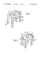
- FIG. 1is a perspective view of the overall plate at a temperature of about 0° C.
- FIG. 2is a perspective view corresponding to FIG. 1 at a positive temperature of 37° C.
- FIG. 3is a plan view of the plate at the 0° C. state.
- FIG. 4is a front view corresponding to FIG. 3 .
- FIG. 5is a plan view of the plate at the 37° C. state.
- FIG. 6is a front view corresponding to FIG. 5 .
- FIG. 7is a front view of part of the spinal column showing the arthrodesis of two vertebral bodies according to the characteristics of the invention.
- FIG. 8is a longitudinal cross section corresponding to FIG. 7 .
- the joining devicecomprises a compact connection element comprising a plate ( 1 ) equipped at each end with anchoring parts in the form of tabs ( 1 a ) and ( 1 b ).
- These anchoring parts ( 1 a ) and ( 1 b )are designed to be engaged in seats previously established in the vertebral bodies to be joined (V 1 ) and (V 2 ), opposite the spinous processes.
- the plate ( 1 ) and its anchoring parts ( 1 a ) and ( 1 b )are made from a shape-memory material in order to correspond to a defined and stable geometric shape at a positive temperature of about 37° C. and to another geometric shape at a much lower temperature of about 0° C. More particularly, at a temperature of about 0° C., the anchoring parts ( 1 a ) and ( 1 b ) are arranged in a substantially vertical plane (FIGS. 1, 3 and 4 ). In this state, it is possible to introduce the anchoring parts ( 1 a ) ( 1 b ) into the corresponding arrangements previously established in the vertebral bodies.
- These arrangementspreferably consist of holes drilled in the vertebral bodies and advantageously having a diameter significantly greater than the space taken up by the tabs in such a way as to prevent wedging on the cortical bone and, consequently, to permit perfect clamping of the spongy bone.
- the anchoring parts ( 1 a ) and ( 1 b )are automatically folded back and in, at an angle towards one another, in order to exert, concomitantly, a constant compression of the vertebral bodies (V 1 ) and (V 2 ) while ensuring perfect anchoring of the plate ( 1 ).
- the two clamping tabs ( 1 a ) of one and the same pairfold back at an angle towards one another, as can be seen in particular in FIG.
- each anchoring part ( 1 a ) and ( 1 b )is connected to the ends of the plate ( 1 ) via a central connection zone ( 1 c ) and ( 1 d ) delimiting two profiled notches ( 1 c 1 ) ( 1 c 2 ) and ( 1 d 1 ) ( 1 d 2 ).
- Each anchoring part ( 1 a ) and ( 1 b )comprises two tabs ( 1 a 1 ) ( 1 a 2 ) and ( 1 b 1 ) ( 1 b 2 ) which are connected at one of their ends via a common branch ( 1 e ) ( 1 f ) which is itself integral with the central connection zone ( 1 c ) ( 1 d ).
- each anchoring partGiven the design of each anchoring part, their deformation, under the effect of temperature variation under the conditions indicated above, has the effect of deforming each of the tabs ( 1 a 1 ) ( 1 a 2 ) and ( 1 b 1 ) ( 1 b 2 ) both in the frontal plane and in the sagittal plane (FIGS. 2, 5 and 6 ). The result of this is that this deformation, under the conditions indicated, of each of the tabs permits a compression both in the area of the plate and in the area of its ends, in order to have a closing together of cortical and spongy bone.
- the anchoring tabs ( 1 a, 1 b )are situated a certain distance from their central connection zone ( 1 c, 1 d ) by means of the interposition of a bridge of material defining a part of the edge of the corresponding notch and this bridge of material can be used to adjust the force or value of the deformation which brings the two tabs of one and the same pair closer to one another at an angle, for example the tabs ( 1 a ) when the positive temperature is reached, the desired blocking clamping between the two tabs of one and the same pair being generally less than the compression clamping of the vertebral bodies against one another ensured by the closing together at an angle of the two pairs of tabs ( 1 a ) and ( 1 b ).
- the plate ( 1 )has a transverse curvature corresponding very substantially to the profile of the anterior face of the vertebral bodies and a longitudinal curvature for adapting to the cervical lordosis. The length of the plate ( 1 ) depends on the number of vertebral bodies to be joined.
- each platetogether with its anchoring parts, is stored at 0° C. or at a negative temperature, in a form permitting the said anchoring parts to be maintained in a vertical position.
- the plate assemblyis easily put into place using an ancillary with which it is possible to make the four seats which will receive the four tabs ( 1 a 1 ) ( 1 a 2 ) and ( 1 b 1 ) ( 1 b 2 ).
- the ancillarycan advantageously be fixed, for example by screwing, in a passage or slot ( 1 h ).
- the plate ( 1 )can also comprise reliefs ( 1 i ) between the pairs of tabs ( 1 a ) ( 1 b ), for example of the order of 5 mm in length and 4 mm in width, extending parallel to the tabs and intended to be introduced between two vertebral bodies upon positioning of the plate, in order to maintain a certain value of the disc space and to relieve the intervertebral disc.
- the platecan be made in one piece by cutting out and folding or by stamping from a sheet of metal, for example nickel titanium, which can be trained by virtue of its shape-memory properties.
Landscapes
- Health & Medical Sciences (AREA)
- Orthopedic Medicine & Surgery (AREA)
- Life Sciences & Earth Sciences (AREA)
- Surgery (AREA)
- Neurology (AREA)
- Heart & Thoracic Surgery (AREA)
- Engineering & Computer Science (AREA)
- Biomedical Technology (AREA)
- Nuclear Medicine, Radiotherapy & Molecular Imaging (AREA)
- Medical Informatics (AREA)
- Molecular Biology (AREA)
- Animal Behavior & Ethology (AREA)
- General Health & Medical Sciences (AREA)
- Public Health (AREA)
- Veterinary Medicine (AREA)
- Prostheses (AREA)
Abstract
Description
Claims (11)
Applications Claiming Priority (3)
| Application Number | Priority Date | Filing Date | Title |
|---|---|---|---|
| FR9612951AFR2754702B1 (en) | 1996-10-18 | 1996-10-18 | DEVICE FOR SOLIDARIZING AT LEAST TWO VERTEBRAL BODIES |
| FR9612951 | 1996-10-18 | ||
| PCT/FR1997/001866WO1998017189A1 (en) | 1996-10-18 | 1997-10-17 | Device for securing at least two vertebrae |
Publications (1)
| Publication Number | Publication Date |
|---|---|
| US6336928B1true US6336928B1 (en) | 2002-01-08 |
Family
ID=9496968
Family Applications (1)
| Application Number | Title | Priority Date | Filing Date |
|---|---|---|---|
| US09/284,569Expired - Fee RelatedUS6336928B1 (en) | 1996-10-18 | 1997-10-17 | Device for securing at least two vertebrae |
Country Status (5)
| Country | Link |
|---|---|
| US (1) | US6336928B1 (en) |
| EP (1) | EP1011506A1 (en) |
| JP (1) | JP2001502572A (en) |
| FR (1) | FR2754702B1 (en) |
| WO (1) | WO1998017189A1 (en) |
Cited By (122)
| Publication number | Priority date | Publication date | Assignee | Title |
|---|---|---|---|---|
| US20030141567A1 (en)* | 1999-06-14 | 2003-07-31 | Salman Akram | Method of improving copper interconnects of semiconductor devices for bonding |
| US20040092929A1 (en)* | 2002-09-27 | 2004-05-13 | Zindrick Michael R. | Spinal plate with means to secure a graft |
| US20040097927A1 (en)* | 2001-02-13 | 2004-05-20 | Yeung Jeffrey E. | Intervertebral disc repair |
| FR2848408A1 (en)* | 2002-12-17 | 2004-06-18 | Vitatech | Spinal fixation device for correcting curvature of spine includes slidable connection for connecting an anchoring screw to a solidifying rod, with slidable connection including a point designed to penetrate a vertebral bone |
| US20040127900A1 (en)* | 2002-12-31 | 2004-07-01 | Konieczynski David D. | Resilient bone plate and screw system allowing bi-directional assembly |
| US20040127899A1 (en)* | 2002-12-31 | 2004-07-01 | Konieczynski David D. | Bone plate and screw system allowing bi-directional attachment |
| US20040153078A1 (en)* | 2003-01-30 | 2004-08-05 | Grinberg Alexander D | Anterior buttress staple |
| US6773437B2 (en)* | 1999-04-23 | 2004-08-10 | Sdgi Holdings, Inc. | Shape memory alloy staple |
| WO2004043186A3 (en)* | 2002-11-08 | 2005-05-12 | Velcro Ind | Active fasteners |
| US20050246873A1 (en)* | 2003-11-07 | 2005-11-10 | Tachauer Ernesto S | Active fasteners |
| US20050277933A1 (en)* | 1999-07-07 | 2005-12-15 | Wall Eric J | Spinal correction system |
| US7048739B2 (en) | 2002-12-31 | 2006-05-23 | Depuy Spine, Inc. | Bone plate and resilient screw system allowing bi-directional assembly |
| WO2006122194A1 (en)* | 2005-05-11 | 2006-11-16 | Children's Hospital Medical Center | Spinal correction system |
| US20070049941A1 (en)* | 2005-08-25 | 2007-03-01 | Lanx, Llc | Plate with stabilization |
| US20070122766A1 (en)* | 2005-11-29 | 2007-05-31 | Wilson Myron A | Alginate band fastener |
| US20070191850A1 (en)* | 2004-08-27 | 2007-08-16 | Depuy Spine, Inc. | Vertebral staples and insertion tools |
| US20070265631A1 (en)* | 2003-02-03 | 2007-11-15 | Biomedical Enterprises, Inc. | System and method for force, displacement, and rate control of shaped memory material implants |
| US20080255620A1 (en)* | 2007-03-30 | 2008-10-16 | Strauss Kevin R | Anterior Vertebral Plate With Spike Fixation |
| US20090149884A1 (en)* | 2007-08-02 | 2009-06-11 | Redyns Medical, Llc | System and method for bridge anchor tendon attachment |
| US20090198277A1 (en)* | 2007-12-28 | 2009-08-06 | Osteomed Spine, Inc. | Bone tissue fixation device and method |
| US20090235494A1 (en)* | 2008-03-19 | 2009-09-24 | Gm Global Technology Operations, Inc. | Active material based fasteners including cable ties and twist ties |
| US20090248090A1 (en)* | 2007-12-28 | 2009-10-01 | Pronto Products, Llc | Rib bone tissue clamp |
| US20090287249A1 (en)* | 2005-09-21 | 2009-11-19 | Children's Hospital Medical Center And Spineform Llc | Orthopedic implant |
| US20090318977A1 (en)* | 2008-06-20 | 2009-12-24 | Giovanni Di Giacomo | Wedged profile plate |
| US20100023062A1 (en)* | 2008-07-24 | 2010-01-28 | Biopro, Inc. | Bone fixation apparatus and method of manufacture |
| US20100094358A1 (en)* | 2008-10-10 | 2010-04-15 | K2M, Inc. | Spinal staple |
| US20100100138A1 (en)* | 2005-09-21 | 2010-04-22 | Reynolds Joseph E | Endoscopic Insturments and Mehod for Delivery of Spinal Implant |
| US20100145391A1 (en)* | 2008-12-05 | 2010-06-10 | Kleiner Jeffrey | Apparatus and method of spinal implant and fusion |
| US20100185240A1 (en)* | 2007-07-03 | 2010-07-22 | Spineart Sa | Bridging device for laminoplasty and applications thereof |
| US20100204796A1 (en)* | 2009-02-11 | 2010-08-12 | IMDS, Inc. | Intervertebral implant with integrated fixation |
| US7799081B2 (en) | 2004-09-14 | 2010-09-21 | Aeolin, Llc | System and method for spinal fusion |
| US20100249935A1 (en)* | 2009-03-30 | 2010-09-30 | Slivka Michael A | Zero Profile Spinal Fusion Cage |
| US8088163B1 (en) | 2008-02-06 | 2012-01-03 | Kleiner Jeffrey B | Tools and methods for spinal fusion |
| USD656610S1 (en) | 2009-02-06 | 2012-03-27 | Kleiner Jeffrey B | Spinal distraction instrument |
| US20120226277A1 (en)* | 2009-08-10 | 2012-09-06 | Virak Orthopedic Research Llc | Orthopedic external fixator and method of use |
| US8328807B2 (en) | 2008-07-09 | 2012-12-11 | Icon Orthopaedic Concepts, Llc | Ankle arthrodesis nail and outrigger assembly |
| US20130079819A1 (en)* | 2011-03-25 | 2013-03-28 | George J. Rohlinger | Suture anchor |
| US8414584B2 (en) | 2008-07-09 | 2013-04-09 | Icon Orthopaedic Concepts, Llc | Ankle arthrodesis nail and outrigger assembly |
| US20140018809A1 (en)* | 2012-01-20 | 2014-01-16 | Dallen Medical, Inc. | Compression bone staple |
| US8647369B2 (en) | 2010-05-19 | 2014-02-11 | Josef E. Gorek | Minimal profile anterior bracket for spinal fixation |
| US8685031B2 (en) | 2009-09-18 | 2014-04-01 | Spinal Surgical Strategies, Llc | Bone graft delivery system |
| US8864654B2 (en) | 2010-04-20 | 2014-10-21 | Jeffrey B. Kleiner | Method and apparatus for performing retro peritoneal dissection |
| US8906028B2 (en) | 2009-09-18 | 2014-12-09 | Spinal Surgical Strategies, Llc | Bone graft delivery device and method of using the same |
| US8911476B2 (en) | 2009-06-23 | 2014-12-16 | Osteomed, Llc | Bone plates, screws, and instruments |
| US8945232B2 (en) | 2012-12-31 | 2015-02-03 | Wright Medical Technology, Inc. | Ball and socket implants for correction of hammer toes and claw toes |
| US8961564B2 (en) | 2008-12-23 | 2015-02-24 | Osteomed Llc | Bone tissue clamp |
| USD723682S1 (en) | 2013-05-03 | 2015-03-03 | Spinal Surgical Strategies, Llc | Bone graft delivery tool |
| US9033993B2 (en) | 2009-11-03 | 2015-05-19 | Howmedica Osteonics Corp. | Intervertebral implant with integrated fixation |
| US9044287B2 (en) | 2010-06-02 | 2015-06-02 | Wright Medical Technology, Inc. | Hammer toe implant method |
| US9060877B2 (en) | 2009-09-18 | 2015-06-23 | Spinal Surgical Strategies, Llc | Fusion cage with combined biological delivery system |
| WO2015131106A1 (en)* | 2014-02-27 | 2015-09-03 | Surgical Design Innovations | Bone fusion/fixation device and related systems and methods |
| US9173694B2 (en) | 2009-09-18 | 2015-11-03 | Spinal Surgical Strategies, Llc | Fusion cage with combined biological delivery system |
| US9186193B2 (en) | 2009-09-18 | 2015-11-17 | Spinal Surgical Strategies, Llc | Fusion cage with combined biological delivery system |
| US9211147B2 (en) | 2009-06-23 | 2015-12-15 | Osteomed Llc | Spinous process fusion implants |
| US9247943B1 (en) | 2009-02-06 | 2016-02-02 | Kleiner Intellectual Property, Llc | Devices and methods for preparing an intervertebral workspace |
| US9248028B2 (en) | 2011-09-16 | 2016-02-02 | DePuy Synthes Products, Inc. | Removable, bone-securing cover plate for intervertebral fusion cage |
| US9254130B2 (en) | 2011-11-01 | 2016-02-09 | Hyun Bae | Blade anchor systems for bone fusion |
| USD750249S1 (en) | 2014-10-20 | 2016-02-23 | Spinal Surgical Strategies, Llc | Expandable fusion cage |
| US9445851B2 (en) | 2009-07-24 | 2016-09-20 | Spinal Usa, Inc. | Bone plate screw-blocking systems and methods |
| US9474561B2 (en) | 2013-11-19 | 2016-10-25 | Wright Medical Technology, Inc. | Two-wire technique for installing hammertoe implant |
| US9480511B2 (en) | 2009-12-17 | 2016-11-01 | Engage Medical Holdings, Llc | Blade fixation for ankle fusion and arthroplasty |
| US9480475B2 (en) | 2012-08-15 | 2016-11-01 | DePuy Synthes Products, Inc. | Bone plate suture anchor |
| US9498266B2 (en) | 2014-02-12 | 2016-11-22 | Wright Medical Technology, Inc. | Intramedullary implant, system, and method for inserting an implant into a bone |
| US9498273B2 (en) | 2010-06-02 | 2016-11-22 | Wright Medical Technology, Inc. | Orthopedic implant kit |
| US9545274B2 (en) | 2014-02-12 | 2017-01-17 | Wright Medical Technology, Inc. | Intramedullary implant, system, and method for inserting an implant into a bone |
| USD777329S1 (en) | 2015-10-19 | 2017-01-24 | Nextremity Solutions, Inc. | Bone staple |
| US9603643B2 (en) | 2010-06-02 | 2017-03-28 | Wright Medical Technology, Inc. | Hammer toe implant with expansion portion for retrograde approach |
| US9615856B2 (en) | 2011-11-01 | 2017-04-11 | Imds Llc | Sacroiliac fusion cage |
| US9629729B2 (en) | 2009-09-18 | 2017-04-25 | Spinal Surgical Strategies, Llc | Biological delivery system with adaptable fusion cage interface |
| US9662225B2 (en) | 2012-03-06 | 2017-05-30 | DePuy Synthes Products, Inc. | Nubbed plate |
| US9687354B2 (en) | 2008-03-26 | 2017-06-27 | DePuy Synthes Products, Inc. | Posterior intervertebral disc inserter and expansion techniques |
| US9700434B2 (en) | 2009-08-10 | 2017-07-11 | Howmedica Osteonics Corp. | Intervertebral implant with integrated fixation |
| US9717403B2 (en) | 2008-12-05 | 2017-08-01 | Jeffrey B. Kleiner | Method and apparatus for performing retro peritoneal dissection |
| US9724140B2 (en) | 2010-06-02 | 2017-08-08 | Wright Medical Technology, Inc. | Tapered, cylindrical cruciform hammer toe implant and method |
| US9724139B2 (en) | 2013-10-01 | 2017-08-08 | Wright Medical Technology, Inc. | Hammer toe implant and method |
| USD797290S1 (en) | 2015-10-19 | 2017-09-12 | Spinal Surgical Strategies, Llc | Bone graft delivery tool |
| US9808296B2 (en) | 2014-09-18 | 2017-11-07 | Wright Medical Technology, Inc. | Hammertoe implant and instrument |
| US20180049787A1 (en)* | 2016-08-17 | 2018-02-22 | Globus Medical, Inc. | Volar distal radius stabilization system |
| US9925051B2 (en) | 2010-12-16 | 2018-03-27 | Engage Medical Holdings, Llc | Arthroplasty systems and methods |
| EP3334365A4 (en)* | 2015-08-12 | 2018-09-19 | Globus Medical, Inc. | Devices and methods for temporary mounting of parts to bone |
| US10080597B2 (en) | 2014-12-19 | 2018-09-25 | Wright Medical Technology, Inc. | Intramedullary anchor for interphalangeal arthrodesis |
| US10182923B2 (en) | 2015-01-14 | 2019-01-22 | Stryker European Holdings I, Llc | Spinal implant with porous and solid surfaces |
| US10182921B2 (en) | 2012-11-09 | 2019-01-22 | DePuy Synthes Products, Inc. | Interbody device with opening to allow packing graft and other biologics |
| US10206787B2 (en) | 2006-12-22 | 2019-02-19 | Medos International Sarl | Composite vertebral spacers and instrument |
| US10238382B2 (en) | 2012-03-26 | 2019-03-26 | Engage Medical Holdings, Llc | Blade anchor for foot and ankle |
| US10245159B1 (en) | 2009-09-18 | 2019-04-02 | Spinal Surgical Strategies, Llc | Bone graft delivery system and method for using same |
| US20190192140A1 (en)* | 2017-12-22 | 2019-06-27 | Ortho Solutions Holdings Limited | Superelastic bone compression staple |
| US10335289B2 (en) | 2010-09-23 | 2019-07-02 | DePuy Synthes Products, Inc. | Stand alone intervertebral fusion device |
| USD853560S1 (en) | 2008-10-09 | 2019-07-09 | Nuvasive, Inc. | Spinal implant insertion device |
| US10369015B2 (en) | 2010-09-23 | 2019-08-06 | DePuy Synthes Products, Inc. | Implant inserter having a laterally-extending dovetail engagement feature |
| US10390955B2 (en) | 2016-09-22 | 2019-08-27 | Engage Medical Holdings, Llc | Bone implants |
| US20190282365A1 (en)* | 2018-03-13 | 2019-09-19 | John Kent Ellington | Continuous compression fixation device for the fusion of an intercalary structural augment |
| RU2701131C1 (en)* | 2018-11-12 | 2019-09-24 | Федеральное государственное бюджетное военное образовательное учреждение высшего образования "Военно-медицинская академия имени С.М. Кирова" Министерства обороны Российской Федерации (ВМедА) | Method of posterior spondylosyndesis with bone defect plasty after laminectomy |
| US10456272B2 (en) | 2017-03-03 | 2019-10-29 | Engage Uni Llc | Unicompartmental knee arthroplasty |
| US10500062B2 (en) | 2009-12-10 | 2019-12-10 | DePuy Synthes Products, Inc. | Bellows-like expandable interbody fusion cage |
| USD870546S1 (en)* | 2018-05-23 | 2019-12-24 | Curtis Almy | Screw-type fencing staple |
| US10537666B2 (en) | 2015-05-18 | 2020-01-21 | Stryker European Holdings I, Llc | Partially resorbable implants and methods |
| US10792081B2 (en) | 2014-08-28 | 2020-10-06 | Nextremity Solutions, Inc. | Bone fixation devices and methods |
| US10835388B2 (en) | 2017-09-20 | 2020-11-17 | Stryker European Operations Holdings Llc | Spinal implants |
| CN112426219A (en)* | 2021-01-01 | 2021-03-02 | 张长江 | Fuse fixed anterior cervical steel sheet system under scope |
| US10940016B2 (en) | 2017-07-05 | 2021-03-09 | Medos International Sarl | Expandable intervertebral fusion cage |
| US10973656B2 (en) | 2009-09-18 | 2021-04-13 | Spinal Surgical Strategies, Inc. | Bone graft delivery system and method for using same |
| US11103239B2 (en)* | 2017-04-21 | 2021-08-31 | Biomet Manufacturing, Llc | Ratchet staple |
| US11266510B2 (en) | 2015-01-14 | 2022-03-08 | Stryker European Operations Holdings Llc | Spinal implant with fluid delivery capabilities |
| US11311289B1 (en) | 2021-06-21 | 2022-04-26 | Pressio Inc. | Compression and fixation systems and processes for using the same |
| US11376136B2 (en) | 2005-04-12 | 2022-07-05 | Moskowitz Family Llc | Expandable spinal implant and tool system |
| US11529241B2 (en) | 2010-09-23 | 2022-12-20 | DePuy Synthes Products, Inc. | Fusion cage with in-line single piece fixation |
| US11540928B2 (en) | 2017-03-03 | 2023-01-03 | Engage Uni Llc | Unicompartmental knee arthroplasty |
| USD977640S1 (en) | 2021-06-21 | 2023-02-07 | Pressio, Inc. | Staple instrument |
| US11642124B2 (en) | 2020-06-16 | 2023-05-09 | Ortho Solutions Holdings Limited | Reinforced bridge superelastic bone compression staple and inserter system |
| US11666455B2 (en) | 2009-09-18 | 2023-06-06 | Spinal Surgical Strategies, Inc., A Nevada Corporation | Bone graft delivery devices, systems and kits |
| USD996480S1 (en) | 2021-06-21 | 2023-08-22 | Pressio Inc. | Boring tool |
| USD998147S1 (en) | 2021-06-21 | 2023-09-05 | Pressio, Inc. | Boring tool handle |
| USD1003436S1 (en) | 2021-08-19 | 2023-10-31 | Medline Industries, Lp | Surgical staple |
| USD1004088S1 (en) | 2021-08-19 | 2023-11-07 | Medline Industries, Lp | Surgical staple |
| US11903849B2 (en) | 2005-04-12 | 2024-02-20 | Moskowitz Family Llc | Intervertebral implant and tool assembly |
| US20240225639A1 (en)* | 2016-07-07 | 2024-07-11 | Medline Industries, Lp | Orthopedic implant, method, and kit |
| US12220123B2 (en) | 2021-08-19 | 2025-02-11 | Medline Industries, Lp | Apparatus and methods for joining bones |
| US12279972B2 (en) | 2008-05-22 | 2025-04-22 | Spinal Surgical Strategies, Inc. | Spinal fusion cage system with inserter |
| US12295625B2 (en) | 2021-08-19 | 2025-05-13 | Medline Industries, Lp | Apparatus and methods for joining bones |
| US12336704B2 (en) | 2023-01-13 | 2025-06-24 | Medline Industries, Lp | Apparatus and methods for joining bones |
| US12376850B2 (en) | 2023-06-22 | 2025-08-05 | Medline Industries, Lp | Surgical staple |
Families Citing this family (7)
| Publication number | Priority date | Publication date | Assignee | Title |
|---|---|---|---|---|
| RU2139008C1 (en)* | 1998-05-06 | 1999-10-10 | Рябуха Николай Павлович | Spondylodesis device |
| RU2139009C1 (en)* | 1998-07-14 | 1999-10-10 | Рябуха Николай Павлович | Spondylodesis device |
| US6299613B1 (en) | 1999-04-23 | 2001-10-09 | Sdgi Holdings, Inc. | Method for the correction of spinal deformities through vertebral body tethering without fusion |
| RU2241415C2 (en)* | 2001-10-22 | 2004-12-10 | Российский научно-исследовательский нейрохирургический институт им. проф. А.Л. Поленова | Endoprosthesis of vertebral column arch |
| RU2283054C1 (en)* | 2005-03-17 | 2006-09-10 | Общество с ограниченной ответственностью "ИЛЬКОМ" | Fixing unit for stabilizing the vertebral column |
| RU2514121C1 (en)* | 2013-02-01 | 2014-04-27 | Закрытое Акционерное Общество "КИМПФ" | Retainer for spinal ligament and bone structure prosthetic repair accompanying laminoplasty |
| US20240293118A1 (en)* | 2023-03-02 | 2024-09-05 | Medartis Ag | Compression fastener, instruments and methods |
Citations (12)
| Publication number | Priority date | Publication date | Assignee | Title |
|---|---|---|---|---|
| US4047524A (en)* | 1975-04-28 | 1977-09-13 | Downs Surgical Limited | Surgical implant spinal staple |
| US4269180A (en)* | 1978-03-30 | 1981-05-26 | Dall Desmond Meiring | Bone fastener for the greater trochanter |
| US5246443A (en)* | 1990-10-30 | 1993-09-21 | Christian Mai | Clip and osteosynthesis plate with dynamic compression and self-retention |
| FR2694696A1 (en) | 1992-08-14 | 1994-02-18 | Memometal Ind | Shape-memory alloy clip for bone fractures - is made from nickel@-titanium@ alloy, and is in form of staple with two branches having contact zones and connection piece |
| US5360430A (en)* | 1993-07-29 | 1994-11-01 | Lin Chih I | Intervertebral locking device |
| US5395372A (en)* | 1993-09-07 | 1995-03-07 | Danek Medical, Inc. | Spinal strut graft holding staple |
| FR2709410A1 (en) | 1993-09-02 | 1995-03-10 | Jbs Sa | Clip plate for osteosynthesis. |
| EP0646353A1 (en) | 1993-09-21 | 1995-04-05 | Christian Mai | Multi-branched ostheosynthesis staple having a dynamic autoretentive compression |
| EP0667127A1 (en) | 1994-02-10 | 1995-08-16 | Acromed B.V. | Device for implantation for the purpose of limiting the movements between two vertebrae |
| US5660188A (en)* | 1991-05-09 | 1997-08-26 | Groiso; Jorge A. | Procedure for applying an elastic clip |
| US5674296A (en)* | 1994-11-14 | 1997-10-07 | Spinal Dynamics Corporation | Human spinal disc prosthesis |
| US5713899A (en)* | 1995-04-27 | 1998-02-03 | Societe Jbs Sa | Cervical cage designed for the performance of intersomatic arthrodesis |
- 1996
- 1996-10-18FRFR9612951Apatent/FR2754702B1/ennot_activeExpired - Fee Related
- 1997
- 1997-10-17USUS09/284,569patent/US6336928B1/ennot_activeExpired - Fee Related
- 1997-10-17JPJP10519033Apatent/JP2001502572A/enactivePending
- 1997-10-17WOPCT/FR1997/001866patent/WO1998017189A1/ennot_activeApplication Discontinuation
- 1997-10-17EPEP97911291Apatent/EP1011506A1/ennot_activeWithdrawn
Patent Citations (12)
| Publication number | Priority date | Publication date | Assignee | Title |
|---|---|---|---|---|
| US4047524A (en)* | 1975-04-28 | 1977-09-13 | Downs Surgical Limited | Surgical implant spinal staple |
| US4269180A (en)* | 1978-03-30 | 1981-05-26 | Dall Desmond Meiring | Bone fastener for the greater trochanter |
| US5246443A (en)* | 1990-10-30 | 1993-09-21 | Christian Mai | Clip and osteosynthesis plate with dynamic compression and self-retention |
| US5660188A (en)* | 1991-05-09 | 1997-08-26 | Groiso; Jorge A. | Procedure for applying an elastic clip |
| FR2694696A1 (en) | 1992-08-14 | 1994-02-18 | Memometal Ind | Shape-memory alloy clip for bone fractures - is made from nickel@-titanium@ alloy, and is in form of staple with two branches having contact zones and connection piece |
| US5360430A (en)* | 1993-07-29 | 1994-11-01 | Lin Chih I | Intervertebral locking device |
| FR2709410A1 (en) | 1993-09-02 | 1995-03-10 | Jbs Sa | Clip plate for osteosynthesis. |
| US5395372A (en)* | 1993-09-07 | 1995-03-07 | Danek Medical, Inc. | Spinal strut graft holding staple |
| EP0646353A1 (en) | 1993-09-21 | 1995-04-05 | Christian Mai | Multi-branched ostheosynthesis staple having a dynamic autoretentive compression |
| EP0667127A1 (en) | 1994-02-10 | 1995-08-16 | Acromed B.V. | Device for implantation for the purpose of limiting the movements between two vertebrae |
| US5674296A (en)* | 1994-11-14 | 1997-10-07 | Spinal Dynamics Corporation | Human spinal disc prosthesis |
| US5713899A (en)* | 1995-04-27 | 1998-02-03 | Societe Jbs Sa | Cervical cage designed for the performance of intersomatic arthrodesis |
Cited By (257)
| Publication number | Priority date | Publication date | Assignee | Title |
|---|---|---|---|---|
| US6773437B2 (en)* | 1999-04-23 | 2004-08-10 | Sdgi Holdings, Inc. | Shape memory alloy staple |
| US20060071336A1 (en)* | 1999-06-14 | 2006-04-06 | Salman Akram | Copper interconnect |
| US20060138660A1 (en)* | 1999-06-14 | 2006-06-29 | Salman Akram | Copper interconnect |
| US7592246B2 (en) | 1999-06-14 | 2009-09-22 | Micron Technology, Inc. | Method and semiconductor device having copper interconnect for bonding |
| US7569934B2 (en) | 1999-06-14 | 2009-08-04 | Micron Technology, Inc. | Copper interconnect |
| US7511363B2 (en) | 1999-06-14 | 2009-03-31 | Micron Technology, Inc. | Copper interconnect |
| US7489041B2 (en) | 1999-06-14 | 2009-02-10 | Micron Technology, Inc. | Copper interconnect |
| US20030141567A1 (en)* | 1999-06-14 | 2003-07-31 | Salman Akram | Method of improving copper interconnects of semiconductor devices for bonding |
| US20040171246A1 (en)* | 1999-06-14 | 2004-09-02 | Salman Akram | Method of improving copper interconnect of semiconductor devices for bonding |
| US6835643B2 (en) | 1999-06-14 | 2004-12-28 | Micron Technology, Inc. | Method of improving copper interconnects of semiconductor devices for bonding |
| US20050098888A1 (en)* | 1999-06-14 | 2005-05-12 | Salman Akram | Method and semiconductor device having copper interconnect for bonding |
| US7345358B2 (en) | 1999-06-14 | 2008-03-18 | Micron Technology, Inc. | Copper interconnect for semiconductor device |
| US20050212128A1 (en)* | 1999-06-14 | 2005-09-29 | Salman Akram | Copper interconnect |
| US7338889B2 (en) | 1999-06-14 | 2008-03-04 | Micron Technology, Inc. | Method of improving copper interconnects of semiconductor devices for bonding |
| US8759970B2 (en) | 1999-06-14 | 2014-06-24 | Round Rock Research, Llc | Semiconductor device having copper interconnect for bonding |
| US20060055057A1 (en)* | 1999-06-14 | 2006-03-16 | Salman Akram | Copper interconnect |
| US20060055059A1 (en)* | 1999-06-14 | 2006-03-16 | Salman Akram | Copper interconnect |
| US20060055060A1 (en)* | 1999-06-14 | 2006-03-16 | Salman Akram | Copper interconnect |
| US20060055058A1 (en)* | 1999-06-14 | 2006-03-16 | Salman Akram | Copper interconnect |
| US20050277933A1 (en)* | 1999-07-07 | 2005-12-15 | Wall Eric J | Spinal correction system |
| US7481830B2 (en) | 1999-07-07 | 2009-01-27 | Children's Hospital Medical Center | Spinal correction system |
| US8021403B2 (en) | 1999-07-07 | 2011-09-20 | Children's Hospital Medical Center | Spinal staple system |
| US20040097927A1 (en)* | 2001-02-13 | 2004-05-20 | Yeung Jeffrey E. | Intervertebral disc repair |
| US20040092929A1 (en)* | 2002-09-27 | 2004-05-13 | Zindrick Michael R. | Spinal plate with means to secure a graft |
| WO2004043186A3 (en)* | 2002-11-08 | 2005-05-12 | Velcro Ind | Active fasteners |
| FR2848408A1 (en)* | 2002-12-17 | 2004-06-18 | Vitatech | Spinal fixation device for correcting curvature of spine includes slidable connection for connecting an anchoring screw to a solidifying rod, with slidable connection including a point designed to penetrate a vertebral bone |
| US7175624B2 (en) | 2002-12-31 | 2007-02-13 | Depuy Spine, Inc. | Bone plate and screw system allowing bi-directional assembly |
| US20040127900A1 (en)* | 2002-12-31 | 2004-07-01 | Konieczynski David D. | Resilient bone plate and screw system allowing bi-directional assembly |
| US9351774B2 (en) | 2002-12-31 | 2016-05-31 | DePuy Synthes Products, Inc. | Resilient bone plate and screw system allowing bi-directional assembly |
| US7914561B2 (en) | 2002-12-31 | 2011-03-29 | Depuy Spine, Inc. | Resilient bone plate and screw system allowing bi-directional assembly |
| US20050273105A1 (en)* | 2002-12-31 | 2005-12-08 | Depuy Spine, Inc. | Bone plate and screw system allowing bi-directional assembly |
| US7981142B2 (en) | 2002-12-31 | 2011-07-19 | Depuy Spine, Inc. | Bone plate and screw system allowing bi-directional assembly |
| US20060241616A1 (en)* | 2002-12-31 | 2006-10-26 | Depuy Spine, Inc. | Bone Plate and Resilient Screw System Allowing Bi-Directional Assembly |
| US7048739B2 (en) | 2002-12-31 | 2006-05-23 | Depuy Spine, Inc. | Bone plate and resilient screw system allowing bi-directional assembly |
| US7651517B2 (en) | 2002-12-31 | 2010-01-26 | Depuy Acromed, Inc. | Bone plate and resilient screw system allowing bi-directional assembly |
| US8747441B2 (en) | 2002-12-31 | 2014-06-10 | Depuy Spine, Inc. | Resilient bone plate and screw system allowing bi-directional assembly |
| US20040127899A1 (en)* | 2002-12-31 | 2004-07-01 | Konieczynski David D. | Bone plate and screw system allowing bi-directional attachment |
| US7341591B2 (en)* | 2003-01-30 | 2008-03-11 | Depuy Spine, Inc. | Anterior buttress staple |
| US20040153078A1 (en)* | 2003-01-30 | 2004-08-05 | Grinberg Alexander D | Anterior buttress staple |
| US10695114B2 (en)* | 2003-02-03 | 2020-06-30 | William Casey Fox | Method for force, displacement, and rate control of shaped memory material implants |
| US20160278825A1 (en)* | 2003-02-03 | 2016-09-29 | William Casey Fox | Force, displacement, and rate controlled shaped memory material implants |
| US20070265631A1 (en)* | 2003-02-03 | 2007-11-15 | Biomedical Enterprises, Inc. | System and method for force, displacement, and rate control of shaped memory material implants |
| US20050246873A1 (en)* | 2003-11-07 | 2005-11-10 | Tachauer Ernesto S | Active fasteners |
| US20070191850A1 (en)* | 2004-08-27 | 2007-08-16 | Depuy Spine, Inc. | Vertebral staples and insertion tools |
| US7883510B2 (en) | 2004-08-27 | 2011-02-08 | Depuy Spine, Inc. | Vertebral staples and insertion tools |
| US20110060338A1 (en)* | 2004-08-27 | 2011-03-10 | Depuy Spine, Inc. | Vertebral staples and insertion tools |
| US8623020B2 (en) | 2004-08-27 | 2014-01-07 | Depuy Spine, Inc. | Vertebral staples and insertion tools |
| US7799081B2 (en) | 2004-09-14 | 2010-09-21 | Aeolin, Llc | System and method for spinal fusion |
| US20100280622A1 (en)* | 2004-09-14 | 2010-11-04 | Aeolin, Llc | System and method for spinal fusion |
| US8562683B2 (en) | 2004-09-14 | 2013-10-22 | Aeolin Llc | System and method for spinal fusion |
| US11903849B2 (en) | 2005-04-12 | 2024-02-20 | Moskowitz Family Llc | Intervertebral implant and tool assembly |
| US11376136B2 (en) | 2005-04-12 | 2022-07-05 | Moskowitz Family Llc | Expandable spinal implant and tool system |
| WO2006122194A1 (en)* | 2005-05-11 | 2006-11-16 | Children's Hospital Medical Center | Spinal correction system |
| US20070049941A1 (en)* | 2005-08-25 | 2007-03-01 | Lanx, Llc | Plate with stabilization |
| US9072554B2 (en) | 2005-09-21 | 2015-07-07 | Children's Hospital Medical Center | Orthopedic implant |
| US20100100138A1 (en)* | 2005-09-21 | 2010-04-22 | Reynolds Joseph E | Endoscopic Insturments and Mehod for Delivery of Spinal Implant |
| US20090287249A1 (en)* | 2005-09-21 | 2009-11-19 | Children's Hospital Medical Center And Spineform Llc | Orthopedic implant |
| US20070122766A1 (en)* | 2005-11-29 | 2007-05-31 | Wilson Myron A | Alginate band fastener |
| US10206787B2 (en) | 2006-12-22 | 2019-02-19 | Medos International Sarl | Composite vertebral spacers and instrument |
| US11020237B2 (en) | 2006-12-22 | 2021-06-01 | Medos International Sarl | Composite vertebral spacers and instrument |
| US20080255620A1 (en)* | 2007-03-30 | 2008-10-16 | Strauss Kevin R | Anterior Vertebral Plate With Spike Fixation |
| US8920479B2 (en)* | 2007-03-30 | 2014-12-30 | K2M, Inc. | Anterior vertebral plate with spike fixation |
| US20100185240A1 (en)* | 2007-07-03 | 2010-07-22 | Spineart Sa | Bridging device for laminoplasty and applications thereof |
| CN101801294B (en)* | 2007-07-03 | 2012-05-30 | 脊柱工艺公司 | Bridging device for laminoplasty and applications thereof |
| US20090149884A1 (en)* | 2007-08-02 | 2009-06-11 | Redyns Medical, Llc | System and method for bridge anchor tendon attachment |
| US8940019B2 (en) | 2007-12-28 | 2015-01-27 | Osteomed Spine, Inc. | Bone tissue fixation device and method |
| US20090248090A1 (en)* | 2007-12-28 | 2009-10-01 | Pronto Products, Llc | Rib bone tissue clamp |
| US20090198277A1 (en)* | 2007-12-28 | 2009-08-06 | Osteomed Spine, Inc. | Bone tissue fixation device and method |
| USD696399S1 (en) | 2008-02-06 | 2013-12-24 | Kleiner Intellectual Property, Llc | Spinal distraction instrument |
| US8088163B1 (en) | 2008-02-06 | 2012-01-03 | Kleiner Jeffrey B | Tools and methods for spinal fusion |
| US8808305B2 (en) | 2008-02-06 | 2014-08-19 | Jeffrey B. Kleiner | Spinal fusion cage system with inserter |
| US8292960B2 (en) | 2008-02-06 | 2012-10-23 | Kleiner Intellectual Property, Llc | Spinal fusion cage with removable planar elements |
| US10179054B2 (en) | 2008-02-06 | 2019-01-15 | Jeffrey B. Kleiner | Spinal fusion cage system with inserter |
| US11129730B2 (en) | 2008-02-06 | 2021-09-28 | Spinal Surgical Strategies, Inc., a Nevada corpora | Spinal fusion cage system with inserter |
| USD700322S1 (en) | 2008-02-06 | 2014-02-25 | Jeffrey B. Kleiner | Intervertebral surgical tool |
| US8277510B2 (en) | 2008-02-06 | 2012-10-02 | Kleiner Intellectual Property, Llc | Tools and methods for spinal fusion |
| US8715355B2 (en) | 2008-02-06 | 2014-05-06 | Nuvasive, Inc. | Spinal fusion cage with removable planar elements |
| US9439782B2 (en) | 2008-02-06 | 2016-09-13 | Jeffrey B. Kleiner | Spinal fusion cage system with inserter |
| US8230555B2 (en)* | 2008-03-19 | 2012-07-31 | GM Global Technology Operations LLC | Active material based fasteners including cable ties and twist ties |
| US20090235494A1 (en)* | 2008-03-19 | 2009-09-24 | Gm Global Technology Operations, Inc. | Active material based fasteners including cable ties and twist ties |
| US10206784B2 (en) | 2008-03-26 | 2019-02-19 | DePuy Synthes Products, Inc. | Posterior intervertebral disc inserter and expansion techniques |
| US9687354B2 (en) | 2008-03-26 | 2017-06-27 | DePuy Synthes Products, Inc. | Posterior intervertebral disc inserter and expansion techniques |
| US12279972B2 (en) | 2008-05-22 | 2025-04-22 | Spinal Surgical Strategies, Inc. | Spinal fusion cage system with inserter |
| US8728131B2 (en)* | 2008-06-20 | 2014-05-20 | Arthrex, Inc. | Wedged Profile Plate |
| US20090318977A1 (en)* | 2008-06-20 | 2009-12-24 | Giovanni Di Giacomo | Wedged profile plate |
| US8414584B2 (en) | 2008-07-09 | 2013-04-09 | Icon Orthopaedic Concepts, Llc | Ankle arthrodesis nail and outrigger assembly |
| US8328807B2 (en) | 2008-07-09 | 2012-12-11 | Icon Orthopaedic Concepts, Llc | Ankle arthrodesis nail and outrigger assembly |
| US9226783B2 (en) | 2008-07-09 | 2016-01-05 | Icon Orthopaedic Concepts, Llc | Ankle arthrodesis nail and outrigger assembly |
| US8062297B2 (en) | 2008-07-24 | 2011-11-22 | Biopro, Inc. | Bone fixation apparatus and method of manufacture |
| US20100023062A1 (en)* | 2008-07-24 | 2010-01-28 | Biopro, Inc. | Bone fixation apparatus and method of manufacture |
| USD853560S1 (en) | 2008-10-09 | 2019-07-09 | Nuvasive, Inc. | Spinal implant insertion device |
| US20100094358A1 (en)* | 2008-10-10 | 2010-04-15 | K2M, Inc. | Spinal staple |
| US9861496B2 (en) | 2008-12-05 | 2018-01-09 | Jeffrey B. Kleiner | Apparatus and method of spinal implant and fusion |
| US9717403B2 (en) | 2008-12-05 | 2017-08-01 | Jeffrey B. Kleiner | Method and apparatus for performing retro peritoneal dissection |
| US10617293B2 (en) | 2008-12-05 | 2020-04-14 | Jeffrey B. Kleiner | Method and apparatus for performing retro peritoneal dissection |
| US20100145391A1 (en)* | 2008-12-05 | 2010-06-10 | Kleiner Jeffrey | Apparatus and method of spinal implant and fusion |
| US8870882B2 (en) | 2008-12-05 | 2014-10-28 | Jeffrey KLEINER | Apparatus and method of spinal implant and fusion |
| US9427264B2 (en) | 2008-12-05 | 2016-08-30 | Jeffrey KLEINER | Apparatus and method of spinal implant and fusion |
| US8366748B2 (en) | 2008-12-05 | 2013-02-05 | Kleiner Jeffrey | Apparatus and method of spinal implant and fusion |
| US8961564B2 (en) | 2008-12-23 | 2015-02-24 | Osteomed Llc | Bone tissue clamp |
| US9247943B1 (en) | 2009-02-06 | 2016-02-02 | Kleiner Intellectual Property, Llc | Devices and methods for preparing an intervertebral workspace |
| USD656610S1 (en) | 2009-02-06 | 2012-03-27 | Kleiner Jeffrey B | Spinal distraction instrument |
| US10201355B2 (en) | 2009-02-06 | 2019-02-12 | Kleiner Intellectual Property, Llc | Angled surgical tool for removing tissue from within an intervertebral space |
| USD667542S1 (en) | 2009-02-06 | 2012-09-18 | Kleiner Jeffrey B | Spinal distraction instrument |
| US9826988B2 (en) | 2009-02-06 | 2017-11-28 | Kleiner Intellectual Property, Llc | Devices and methods for preparing an intervertebral workspace |
| US8821555B2 (en)* | 2009-02-11 | 2014-09-02 | Howmedica Osteonics Corp. | Intervertebral implant with integrated fixation |
| US9788968B2 (en) | 2009-02-11 | 2017-10-17 | Howmedica Osteonics Corp. | Intervertebral implant with integrated fixation |
| US8349015B2 (en) | 2009-02-11 | 2013-01-08 | Howmedica Osteonics Corp. | Intervertebral implant with integrated fixation |
| US9138276B2 (en) | 2009-02-11 | 2015-09-22 | Howmedica Osteonics Corp. | Intervertebral implant with integrated fixation |
| US9138275B2 (en) | 2009-02-11 | 2015-09-22 | Howmedica Osteonics Corp. | Intervertebral implant with integrated fixation |
| US8287572B2 (en)* | 2009-02-11 | 2012-10-16 | Howmedica Osteonics Corp. | Intervertebral implant with integrated fixation |
| US20100204737A1 (en)* | 2009-02-11 | 2010-08-12 | IMDS, Inc. | Intervertebral implant with integrated fixation |
| US20100204739A1 (en)* | 2009-02-11 | 2010-08-12 | IMDS, Inc. | Intervertebral implant with integrated fixation |
| US20100204796A1 (en)* | 2009-02-11 | 2010-08-12 | IMDS, Inc. | Intervertebral implant with integrated fixation |
| US10271959B2 (en) | 2009-02-11 | 2019-04-30 | Howmedica Osteonics Corp. | Intervertebral implant with integrated fixation |
| US10624758B2 (en) | 2009-03-30 | 2020-04-21 | DePuy Synthes Products, Inc. | Zero profile spinal fusion cage |
| US9592129B2 (en) | 2009-03-30 | 2017-03-14 | DePuy Synthes Products, Inc. | Zero profile spinal fusion cage |
| US20100249935A1 (en)* | 2009-03-30 | 2010-09-30 | Slivka Michael A | Zero Profile Spinal Fusion Cage |
| US11612491B2 (en) | 2009-03-30 | 2023-03-28 | DePuy Synthes Products, Inc. | Zero profile spinal fusion cage |
| US9526620B2 (en) | 2009-03-30 | 2016-12-27 | DePuy Synthes Products, Inc. | Zero profile spinal fusion cage |
| US12097124B2 (en) | 2009-03-30 | 2024-09-24 | DePuy Synthes Products, Inc. | Zero profile spinal fusion cage |
| US8911476B2 (en) | 2009-06-23 | 2014-12-16 | Osteomed, Llc | Bone plates, screws, and instruments |
| US9456858B2 (en) | 2009-06-23 | 2016-10-04 | Osteomed, Llc | Bone plates, screws and instruments |
| US9211147B2 (en) | 2009-06-23 | 2015-12-15 | Osteomed Llc | Spinous process fusion implants |
| US10010356B2 (en) | 2009-06-23 | 2018-07-03 | Wenzel Spine, Inc. | Bone plates, screws and instruments |
| US9445851B2 (en) | 2009-07-24 | 2016-09-20 | Spinal Usa, Inc. | Bone plate screw-blocking systems and methods |
| US9066757B2 (en)* | 2009-08-10 | 2015-06-30 | Virak Orthopedic Research Llc | Orthopedic external fixator and method of use |
| US9700434B2 (en) | 2009-08-10 | 2017-07-11 | Howmedica Osteonics Corp. | Intervertebral implant with integrated fixation |
| US20120226277A1 (en)* | 2009-08-10 | 2012-09-06 | Virak Orthopedic Research Llc | Orthopedic external fixator and method of use |
| US10687964B2 (en) | 2009-08-10 | 2020-06-23 | Howmedica Osteonics Corp. | Intervertebral implant with integrated fixation |
| US11660208B2 (en) | 2009-09-18 | 2023-05-30 | Spinal Surgical Strategies, Inc. | Bone graft delivery system and method for using same |
| US9629729B2 (en) | 2009-09-18 | 2017-04-25 | Spinal Surgical Strategies, Llc | Biological delivery system with adaptable fusion cage interface |
| US11666455B2 (en) | 2009-09-18 | 2023-06-06 | Spinal Surgical Strategies, Inc., A Nevada Corporation | Bone graft delivery devices, systems and kits |
| US10973656B2 (en) | 2009-09-18 | 2021-04-13 | Spinal Surgical Strategies, Inc. | Bone graft delivery system and method for using same |
| US12053393B2 (en) | 2009-09-18 | 2024-08-06 | Spinal Surgical Strategies, Inc. | Bone graft delivery system and method for use |
| US10245159B1 (en) | 2009-09-18 | 2019-04-02 | Spinal Surgical Strategies, Llc | Bone graft delivery system and method for using same |
| US9060877B2 (en) | 2009-09-18 | 2015-06-23 | Spinal Surgical Strategies, Llc | Fusion cage with combined biological delivery system |
| US9186193B2 (en) | 2009-09-18 | 2015-11-17 | Spinal Surgical Strategies, Llc | Fusion cage with combined biological delivery system |
| US12167971B2 (en) | 2009-09-18 | 2024-12-17 | Spinal Surgical Strategies, Inc. | Bone graft delivery devices, systems and kits |
| US8709088B2 (en) | 2009-09-18 | 2014-04-29 | Spinal Surgical Strategies, Llc | Fusion cage with combined biological delivery system |
| US10195053B2 (en) | 2009-09-18 | 2019-02-05 | Spinal Surgical Strategies, Llc | Bone graft delivery system and method for using same |
| US8906028B2 (en) | 2009-09-18 | 2014-12-09 | Spinal Surgical Strategies, Llc | Bone graft delivery device and method of using the same |
| US8685031B2 (en) | 2009-09-18 | 2014-04-01 | Spinal Surgical Strategies, Llc | Bone graft delivery system |
| US9173694B2 (en) | 2009-09-18 | 2015-11-03 | Spinal Surgical Strategies, Llc | Fusion cage with combined biological delivery system |
| US10799370B2 (en) | 2009-11-03 | 2020-10-13 | Howmedica Osteonics Corp. | Intervertebral implant with integrated fixation |
| US9033993B2 (en) | 2009-11-03 | 2015-05-19 | Howmedica Osteonics Corp. | Intervertebral implant with integrated fixation |
| US9861498B2 (en) | 2009-11-03 | 2018-01-09 | Howmedica Osteonics Corp. | Intervertebral implant with integrated fixation |
| US11628071B2 (en) | 2009-11-03 | 2023-04-18 | Howmedica Osteonics Corp. | Intervertebral implant with integrated fixation |
| US10500062B2 (en) | 2009-12-10 | 2019-12-10 | DePuy Synthes Products, Inc. | Bellows-like expandable interbody fusion cage |
| US11607321B2 (en) | 2009-12-10 | 2023-03-21 | DePuy Synthes Products, Inc. | Bellows-like expandable interbody fusion cage |
| US10238426B2 (en) | 2009-12-17 | 2019-03-26 | Engage Medical Holdings, Llc | Blade fixation for ankle fusion and arthroplasty |
| US9480511B2 (en) | 2009-12-17 | 2016-11-01 | Engage Medical Holdings, Llc | Blade fixation for ankle fusion and arthroplasty |
| US8864654B2 (en) | 2010-04-20 | 2014-10-21 | Jeffrey B. Kleiner | Method and apparatus for performing retro peritoneal dissection |
| US8647369B2 (en) | 2010-05-19 | 2014-02-11 | Josef E. Gorek | Minimal profile anterior bracket for spinal fixation |
| US8945191B2 (en) | 2010-05-19 | 2015-02-03 | K2M, Inc. | Minimal profile anterior bracket for spinal fixation |
| US9498273B2 (en) | 2010-06-02 | 2016-11-22 | Wright Medical Technology, Inc. | Orthopedic implant kit |
| US9724140B2 (en) | 2010-06-02 | 2017-08-08 | Wright Medical Technology, Inc. | Tapered, cylindrical cruciform hammer toe implant and method |
| US9603643B2 (en) | 2010-06-02 | 2017-03-28 | Wright Medical Technology, Inc. | Hammer toe implant with expansion portion for retrograde approach |
| US10736676B2 (en) | 2010-06-02 | 2020-08-11 | Wright Medical Technology, Inc. | Orthopedic implant kit |
| US9877753B2 (en) | 2010-06-02 | 2018-01-30 | Wright Medical Technology, Inc. | Orthopedic implant kit |
| US9949775B2 (en) | 2010-06-02 | 2018-04-24 | Wright Medical Technology, Inc. | Hammer toe implant with expansion portion for retrograde approach |
| US9044287B2 (en) | 2010-06-02 | 2015-06-02 | Wright Medical Technology, Inc. | Hammer toe implant method |
| US10369015B2 (en) | 2010-09-23 | 2019-08-06 | DePuy Synthes Products, Inc. | Implant inserter having a laterally-extending dovetail engagement feature |
| EP3744292A1 (en) | 2010-09-23 | 2020-12-02 | DePuy Synthes Products, LLC | Stand alone intervertebral fusion device |
| US11382768B2 (en) | 2010-09-23 | 2022-07-12 | DePuy Synthes Products, Inc. | Implant inserter having a laterally-extending dovetail engagement feature |
| US11529241B2 (en) | 2010-09-23 | 2022-12-20 | DePuy Synthes Products, Inc. | Fusion cage with in-line single piece fixation |
| US10335289B2 (en) | 2010-09-23 | 2019-07-02 | DePuy Synthes Products, Inc. | Stand alone intervertebral fusion device |
| US11678996B2 (en) | 2010-09-23 | 2023-06-20 | DePuy Synthes Products, Inc. | Stand alone intervertebral fusion device |
| US12109127B2 (en) | 2010-09-23 | 2024-10-08 | DePuy Synthes Products, Inc. | Implant inserter having a laterally-extending dovetail engagement feature |
| US11197763B2 (en) | 2010-12-16 | 2021-12-14 | Engage Medical Holdings, Llc | Arthroplasty systems and methods |
| US10342667B2 (en) | 2010-12-16 | 2019-07-09 | Engage Medical Holdings, Llc | Arthroplasty systems and methods |
| US9925051B2 (en) | 2010-12-16 | 2018-03-27 | Engage Medical Holdings, Llc | Arthroplasty systems and methods |
| US9039739B2 (en)* | 2011-03-25 | 2015-05-26 | Redyns Medical Llc | Suture anchor |
| US9320514B2 (en) | 2011-03-25 | 2016-04-26 | Redyns Medical Llc | Suture anchor |
| US20130079819A1 (en)* | 2011-03-25 | 2013-03-28 | George J. Rohlinger | Suture anchor |
| US10813773B2 (en) | 2011-09-16 | 2020-10-27 | DePuy Synthes Products, Inc. | Removable, bone-securing cover plate for intervertebral fusion cage |
| US9248028B2 (en) | 2011-09-16 | 2016-02-02 | DePuy Synthes Products, Inc. | Removable, bone-securing cover plate for intervertebral fusion cage |
| US10159582B2 (en) | 2011-09-16 | 2018-12-25 | DePuy Synthes Products, Inc. | Removable, bone-securing cover plate for intervertebral fusion cage |
| US9615856B2 (en) | 2011-11-01 | 2017-04-11 | Imds Llc | Sacroiliac fusion cage |
| US10245090B2 (en) | 2011-11-01 | 2019-04-02 | Engage Medical Holdings, Llc | Blade anchor systems for bone fusion |
| US9254130B2 (en) | 2011-11-01 | 2016-02-09 | Hyun Bae | Blade anchor systems for bone fusion |
| US10064618B2 (en)* | 2012-01-20 | 2018-09-04 | Zimmer, Inc. | Compression bone staple |
| US20140018809A1 (en)* | 2012-01-20 | 2014-01-16 | Dallen Medical, Inc. | Compression bone staple |
| US9662225B2 (en) | 2012-03-06 | 2017-05-30 | DePuy Synthes Products, Inc. | Nubbed plate |
| US9872781B2 (en) | 2012-03-06 | 2018-01-23 | DePuy Synthes Products, Inc. | Nubbed plate |
| US11844702B2 (en) | 2012-03-06 | 2023-12-19 | DePuy Synthes Products, Inc. | Nubbed plate |
| US10327915B2 (en) | 2012-03-06 | 2019-06-25 | DePuy Synthes Products, Inc. | Nubbed plate |
| US11071634B2 (en) | 2012-03-06 | 2021-07-27 | DePuy Synthes Products, Inc. | Nubbed plate |
| US9668877B2 (en) | 2012-03-06 | 2017-06-06 | DePuy Synthes Products, Inc. | Nubbed plate |
| US10238382B2 (en) | 2012-03-26 | 2019-03-26 | Engage Medical Holdings, Llc | Blade anchor for foot and ankle |
| US10182853B2 (en) | 2012-08-15 | 2019-01-22 | DePuy Synthes Products, Inc. | Bone plate suture anchor |
| US9480475B2 (en) | 2012-08-15 | 2016-11-01 | DePuy Synthes Products, Inc. | Bone plate suture anchor |
| US10182921B2 (en) | 2012-11-09 | 2019-01-22 | DePuy Synthes Products, Inc. | Interbody device with opening to allow packing graft and other biologics |
| US11497616B2 (en) | 2012-11-09 | 2022-11-15 | DePuy Synthes Products, Inc. | Interbody device with opening to allow packing graft and other biologics |
| US10278828B2 (en) | 2012-12-31 | 2019-05-07 | Wright Medical Technology, Inc. | Ball and socket implants for correction of hammer toes and claw toes |
| US9504582B2 (en) | 2012-12-31 | 2016-11-29 | Wright Medical Technology, Inc. | Ball and socket implants for correction of hammer toes and claw toes |
| US8945232B2 (en) | 2012-12-31 | 2015-02-03 | Wright Medical Technology, Inc. | Ball and socket implants for correction of hammer toes and claw toes |
| USD723682S1 (en) | 2013-05-03 | 2015-03-03 | Spinal Surgical Strategies, Llc | Bone graft delivery tool |
| US9724139B2 (en) | 2013-10-01 | 2017-08-08 | Wright Medical Technology, Inc. | Hammer toe implant and method |
| US9474561B2 (en) | 2013-11-19 | 2016-10-25 | Wright Medical Technology, Inc. | Two-wire technique for installing hammertoe implant |
| US9675392B2 (en) | 2013-11-19 | 2017-06-13 | Wright Medical Technology, Inc. | Two-wire technique for installing hammertoe implant |
| US9545274B2 (en) | 2014-02-12 | 2017-01-17 | Wright Medical Technology, Inc. | Intramedullary implant, system, and method for inserting an implant into a bone |
| US9498266B2 (en) | 2014-02-12 | 2016-11-22 | Wright Medical Technology, Inc. | Intramedullary implant, system, and method for inserting an implant into a bone |
| US11660131B2 (en) | 2014-02-27 | 2023-05-30 | Exotoe Llc | Bone fusion/fixation device and related systems and methods |
| US10849664B2 (en)* | 2014-02-27 | 2020-12-01 | Exotoe Llc | Bone fusion/fixation device and related systems and methods |
| US10080599B2 (en) | 2014-02-27 | 2018-09-25 | SurgicalDesignInnovations | Bone fusion/fixation device and related systems and methods |
| WO2015131106A1 (en)* | 2014-02-27 | 2015-09-03 | Surgical Design Innovations | Bone fusion/fixation device and related systems and methods |
| US10792081B2 (en) | 2014-08-28 | 2020-10-06 | Nextremity Solutions, Inc. | Bone fixation devices and methods |
| US11234743B2 (en) | 2014-08-28 | 2022-02-01 | Nextremity Solutions, Inc. | Bone fixation devices and methods |
| US9808296B2 (en) | 2014-09-18 | 2017-11-07 | Wright Medical Technology, Inc. | Hammertoe implant and instrument |
| US10299840B2 (en) | 2014-09-18 | 2019-05-28 | Wright Medical Technology, Inc. | Hammertoe implant and instrument |
| USD750249S1 (en) | 2014-10-20 | 2016-02-23 | Spinal Surgical Strategies, Llc | Expandable fusion cage |
| US10080597B2 (en) | 2014-12-19 | 2018-09-25 | Wright Medical Technology, Inc. | Intramedullary anchor for interphalangeal arthrodesis |
| US10182923B2 (en) | 2015-01-14 | 2019-01-22 | Stryker European Holdings I, Llc | Spinal implant with porous and solid surfaces |
| US11000386B2 (en) | 2015-01-14 | 2021-05-11 | Stryker European Holdings I, Llc | Spinal implant with porous and solid surfaces |
| US11266510B2 (en) | 2015-01-14 | 2022-03-08 | Stryker European Operations Holdings Llc | Spinal implant with fluid delivery capabilities |
| US12268613B2 (en) | 2015-01-14 | 2025-04-08 | Stryker European Operations Holdings Llc | Spinal implant with porous and solid surfaces |
| US10537666B2 (en) | 2015-05-18 | 2020-01-21 | Stryker European Holdings I, Llc | Partially resorbable implants and methods |
| US12263279B2 (en) | 2015-05-18 | 2025-04-01 | Stryker European Operations Holdings Llc | Partially resorbable implants and methods |
| US11623027B2 (en) | 2015-05-18 | 2023-04-11 | Stryker European Operations Holdings Llc | Partially resorbable implants and methods |
| US10786313B2 (en) | 2015-08-12 | 2020-09-29 | Globus Medical, Inc. | Devices and methods for temporary mounting of parts to bone |
| US11751950B2 (en)* | 2015-08-12 | 2023-09-12 | Globus Medical Inc. | Devices and methods for temporary mounting of parts to bone |
| EP3334365A4 (en)* | 2015-08-12 | 2018-09-19 | Globus Medical, Inc. | Devices and methods for temporary mounting of parts to bone |
| USD777329S1 (en) | 2015-10-19 | 2017-01-24 | Nextremity Solutions, Inc. | Bone staple |
| USD797290S1 (en) | 2015-10-19 | 2017-09-12 | Spinal Surgical Strategies, Llc | Bone graft delivery tool |
| US20240225639A1 (en)* | 2016-07-07 | 2024-07-11 | Medline Industries, Lp | Orthopedic implant, method, and kit |
| US12285165B2 (en)* | 2016-07-07 | 2025-04-29 | Medline Industries, Lp | Orthopedic implant, method, and kit |
| US20180049787A1 (en)* | 2016-08-17 | 2018-02-22 | Globus Medical, Inc. | Volar distal radius stabilization system |
| US10420596B2 (en)* | 2016-08-17 | 2019-09-24 | Globus Medical, Inc. | Volar distal radius stabilization system |
| US10390955B2 (en) | 2016-09-22 | 2019-08-27 | Engage Medical Holdings, Llc | Bone implants |
| US11540928B2 (en) | 2017-03-03 | 2023-01-03 | Engage Uni Llc | Unicompartmental knee arthroplasty |
| US11369488B2 (en) | 2017-03-03 | 2022-06-28 | Engage Uni Llc | Unicompartmental knee arthroplasty |
| US10456272B2 (en) | 2017-03-03 | 2019-10-29 | Engage Uni Llc | Unicompartmental knee arthroplasty |
| US11103239B2 (en)* | 2017-04-21 | 2021-08-31 | Biomet Manufacturing, Llc | Ratchet staple |
| US10940016B2 (en) | 2017-07-05 | 2021-03-09 | Medos International Sarl | Expandable intervertebral fusion cage |
| US11622867B2 (en) | 2017-09-20 | 2023-04-11 | Stryker European Operations Holdings Llc | Spinal implants |
| US10835388B2 (en) | 2017-09-20 | 2020-11-17 | Stryker European Operations Holdings Llc | Spinal implants |
| US12133806B2 (en) | 2017-09-20 | 2024-11-05 | Stryker European Operations Holdings Llc | Spinal implants |
| US20190192140A1 (en)* | 2017-12-22 | 2019-06-27 | Ortho Solutions Holdings Limited | Superelastic bone compression staple |
| US10987101B2 (en)* | 2017-12-22 | 2021-04-27 | Ortho Solutions Holdings Limited | Superelastic bone compression staple |
| US10918484B2 (en)* | 2018-03-13 | 2021-02-16 | Pressio, Inc. | Continuous compression fixation device for the fusion of an intercalary structural augment |
| US20190282365A1 (en)* | 2018-03-13 | 2019-09-19 | John Kent Ellington | Continuous compression fixation device for the fusion of an intercalary structural augment |
| USD870546S1 (en)* | 2018-05-23 | 2019-12-24 | Curtis Almy | Screw-type fencing staple |
| RU2701131C1 (en)* | 2018-11-12 | 2019-09-24 | Федеральное государственное бюджетное военное образовательное учреждение высшего образования "Военно-медицинская академия имени С.М. Кирова" Министерства обороны Российской Федерации (ВМедА) | Method of posterior spondylosyndesis with bone defect plasty after laminectomy |
| US11642124B2 (en) | 2020-06-16 | 2023-05-09 | Ortho Solutions Holdings Limited | Reinforced bridge superelastic bone compression staple and inserter system |
| CN112426219A (en)* | 2021-01-01 | 2021-03-02 | 张长江 | Fuse fixed anterior cervical steel sheet system under scope |
| USD977640S1 (en) | 2021-06-21 | 2023-02-07 | Pressio, Inc. | Staple instrument |
| US11974739B1 (en) | 2021-06-21 | 2024-05-07 | Pressio Inc. | Compression and fixation systems and processes for using the same |
| USD998147S1 (en) | 2021-06-21 | 2023-09-05 | Pressio, Inc. | Boring tool handle |
| USD996480S1 (en) | 2021-06-21 | 2023-08-22 | Pressio Inc. | Boring tool |
| US11311289B1 (en) | 2021-06-21 | 2022-04-26 | Pressio Inc. | Compression and fixation systems and processes for using the same |
| USD1004088S1 (en) | 2021-08-19 | 2023-11-07 | Medline Industries, Lp | Surgical staple |
| US12220123B2 (en) | 2021-08-19 | 2025-02-11 | Medline Industries, Lp | Apparatus and methods for joining bones |
| USD1003436S1 (en) | 2021-08-19 | 2023-10-31 | Medline Industries, Lp | Surgical staple |
| US12295625B2 (en) | 2021-08-19 | 2025-05-13 | Medline Industries, Lp | Apparatus and methods for joining bones |
| US12336704B2 (en) | 2023-01-13 | 2025-06-24 | Medline Industries, Lp | Apparatus and methods for joining bones |
| US12376850B2 (en) | 2023-06-22 | 2025-08-05 | Medline Industries, Lp | Surgical staple |
Also Published As
| Publication number | Publication date |
|---|---|
| JP2001502572A (en) | 2001-02-27 |
| EP1011506A1 (en) | 2000-06-28 |
| WO1998017189A1 (en) | 1998-04-30 |
| FR2754702A1 (en) | 1998-04-24 |
| FR2754702B1 (en) | 1999-01-08 |
Similar Documents
| Publication | Publication Date | Title |
|---|---|---|
| US6336928B1 (en) | Device for securing at least two vertebrae | |
| US11813175B2 (en) | Spinous process fixation system and methods thereof | |
| US6743257B2 (en) | Dynamic implanted intervertebral spacer | |
| US6837905B1 (en) | Spinal vertebral fusion implant and method | |
| US8641765B2 (en) | Posterior spinal implant system | |
| US5180381A (en) | Anterior lumbar/cervical bicortical compression plate | |
| EP1890616B1 (en) | Anterior cervical plate | |
| US8273127B2 (en) | Interbody fusion device and associated methods | |
| US6743255B2 (en) | Spinal fusion cage with lordosis correction | |
| US7341591B2 (en) | Anterior buttress staple | |
| US5941880A (en) | Coupling member for cross-linking intervertebral cage devices | |
| US5951553A (en) | Methods and apparatus for fusionless treatment of spinal deformities | |
| US8343190B1 (en) | Systems and methods for spinous process fixation | |
| US6652527B2 (en) | Supplemental spine fixation device and method | |
| US7780708B2 (en) | Implant retaining device | |
| US20090292314A1 (en) | Lumbar interspinous prosthesis and its applications | |
| WO2013058901A1 (en) | Spinous process plate and connector assembly and method | |
| EP3228268A1 (en) | Interspinous omnidirectional dynamic stabilization device | |
| US20230165603A1 (en) | Bone anchor with deployable purchase element | |
| WO2007050220A1 (en) | Laminar hook spring | |
| EP3863544B1 (en) | Improved interlaminar-type intervertebral support device | |
| AT408310B (en) | Implant |
Legal Events
| Date | Code | Title | Description |
|---|---|---|---|
| AS | Assignment | Owner name:FRANCE, DEPUY, FRANCE Free format text:ASSIGNMENT OF ASSIGNORS INTEREST;ASSIGNORS:GUERIN, JEAN;ROBERT, ROGER;TREMOULET, MICHEL;AND OTHERS;REEL/FRAME:010721/0121 Effective date:19990612 Owner name:GUERIN, JEAN, FRANCE Free format text:ASSIGNMENT OF ASSIGNORS INTEREST;ASSIGNORS:GUERIN, JEAN;ROBERT, ROGER;TREMOULET, MICHEL;AND OTHERS;REEL/FRAME:010721/0121 Effective date:19990612 Owner name:ROBERT, ROGER, FRANCE Free format text:ASSIGNMENT OF ASSIGNORS INTEREST;ASSIGNORS:GUERIN, JEAN;ROBERT, ROGER;TREMOULET, MICHEL;AND OTHERS;REEL/FRAME:010721/0121 Effective date:19990612 Owner name:TREMOULET, MICHEL, FRANCE Free format text:ASSIGNMENT OF ASSIGNORS INTEREST;ASSIGNORS:GUERIN, JEAN;ROBERT, ROGER;TREMOULET, MICHEL;AND OTHERS;REEL/FRAME:010721/0121 Effective date:19990612 Owner name:JOURDAN, PHILIPPE, FRANCE Free format text:ASSIGNMENT OF ASSIGNORS INTEREST;ASSIGNORS:GUERIN, JEAN;ROBERT, ROGER;TREMOULET, MICHEL;AND OTHERS;REEL/FRAME:010721/0121 Effective date:19990612 Owner name:SAN GALLI, FRANCOIS, FRANCE Free format text:ASSIGNMENT OF ASSIGNORS INTEREST;ASSIGNORS:GUERIN, JEAN;ROBERT, ROGER;TREMOULET, MICHEL;AND OTHERS;REEL/FRAME:010721/0121 Effective date:19990612 | |
| FEPP | Fee payment procedure | Free format text:PAYOR NUMBER ASSIGNED (ORIGINAL EVENT CODE: ASPN); ENTITY STATUS OF PATENT OWNER: LARGE ENTITY | |
| REMI | Maintenance fee reminder mailed | ||
| LAPS | Lapse for failure to pay maintenance fees | ||
| STCH | Information on status: patent discontinuation | Free format text:PATENT EXPIRED DUE TO NONPAYMENT OF MAINTENANCE FEES UNDER 37 CFR 1.362 | |
| FP | Lapsed due to failure to pay maintenance fee | Effective date:20060108 |