US6336365B1 - Low-cost accelerometer - Google Patents
Low-cost accelerometerDownload PDFInfo
- Publication number
- US6336365B1 US6336365B1US09/382,049US38204999AUS6336365B1US 6336365 B1US6336365 B1US 6336365B1US 38204999 AUS38204999 AUS 38204999AUS 6336365 B1US6336365 B1US 6336365B1
- Authority
- US
- United States
- Prior art keywords
- transducer
- capacitor
- acceleration
- section
- circuit board
- Prior art date
- Legal status (The legal status is an assumption and is not a legal conclusion. Google has not performed a legal analysis and makes no representation as to the accuracy of the status listed.)
- Expired - Lifetime
Links
- 230000001133accelerationEffects0.000claimsabstractdescription101
- 239000003990capacitorSubstances0.000claimsabstractdescription66
- 230000004044responseEffects0.000claimsabstractdescription36
- 230000007935neutral effectEffects0.000claimsabstractdescription35
- 239000004020conductorSubstances0.000claimsdescription36
- 238000000034methodMethods0.000claimsdescription28
- 238000012544monitoring processMethods0.000claimsdescription25
- 239000000463materialSubstances0.000claimsdescription21
- 238000013016dampingMethods0.000claimsdescription12
- 238000005452bendingMethods0.000claimsdescription6
- 230000008602contractionEffects0.000claimsdescription6
- 238000010008shearingMethods0.000claims2
- 239000002648laminated materialSubstances0.000claims1
- 230000006835compressionEffects0.000description10
- 238000007906compressionMethods0.000description10
- 230000008859changeEffects0.000description8
- 239000006260foamSubstances0.000description8
- 238000010586diagramMethods0.000description5
- 230000005684electric fieldEffects0.000description5
- 239000000919ceramicSubstances0.000description3
- 230000000694effectsEffects0.000description3
- 239000002184metalSubstances0.000description3
- 229910052751metalInorganic materials0.000description3
- 239000000126substanceSubstances0.000description3
- 230000004075alterationEffects0.000description2
- 230000008901benefitEffects0.000description2
- 239000013078crystalSubstances0.000description2
- 230000007423decreaseEffects0.000description2
- 230000006872improvementEffects0.000description2
- 230000003278mimic effectEffects0.000description2
- 230000004048modificationEffects0.000description2
- 238000012986modificationMethods0.000description2
- 239000004033plasticSubstances0.000description2
- 230000035945sensitivityEffects0.000description2
- QNRATNLHPGXHMA-XZHTYLCXSA-N(r)-(6-ethoxyquinolin-4-yl)-[(2s,4s,5r)-5-ethyl-1-azabicyclo[2.2.2]octan-2-yl]methanol;hydrochlorideChemical compoundCl.C([C@H]([C@H](C1)CC)C2)CN1[C@@H]2[C@H](O)C1=CC=NC2=CC=C(OCC)C=C21QNRATNLHPGXHMA-XZHTYLCXSA-N0.000description1
- 239000004593EpoxySubstances0.000description1
- RTAQQCXQSZGOHL-UHFFFAOYSA-NTitaniumChemical compound[Ti]RTAQQCXQSZGOHL-UHFFFAOYSA-N0.000description1
- 239000000853adhesiveSubstances0.000description1
- 230000001070adhesive effectEffects0.000description1
- JRPBQTZRNDNNOP-UHFFFAOYSA-Nbarium titanateChemical compound[Ba+2].[Ba+2].[O-][Ti]([O-])([O-])[O-]JRPBQTZRNDNNOP-UHFFFAOYSA-N0.000description1
- 229910002113barium titanateInorganic materials0.000description1
- 239000003985ceramic capacitorSubstances0.000description1
- 230000003247decreasing effectEffects0.000description1
- 230000001066destructive effectEffects0.000description1
- 238000001514detection methodMethods0.000description1
- 239000003989dielectric materialSubstances0.000description1
- 239000011152fibreglassSubstances0.000description1
- 238000010304firingMethods0.000description1
- 239000011521glassSubstances0.000description1
- 230000010287polarizationEffects0.000description1
- 230000008569processEffects0.000description1
- 239000010453quartzSubstances0.000description1
- VYPSYNLAJGMNEJ-UHFFFAOYSA-Nsilicon dioxideInorganic materialsO=[Si]=OVYPSYNLAJGMNEJ-UHFFFAOYSA-N0.000description1
- 239000000758substrateSubstances0.000description1
Images


Classifications
- G—PHYSICS
- G01—MEASURING; TESTING
- G01P—MEASURING LINEAR OR ANGULAR SPEED, ACCELERATION, DECELERATION, OR SHOCK; INDICATING PRESENCE, ABSENCE, OR DIRECTION, OF MOVEMENT
- G01P15/00—Measuring acceleration; Measuring deceleration; Measuring shock, i.e. sudden change of acceleration
- G01P15/02—Measuring acceleration; Measuring deceleration; Measuring shock, i.e. sudden change of acceleration by making use of inertia forces using solid seismic masses
- G01P15/08—Measuring acceleration; Measuring deceleration; Measuring shock, i.e. sudden change of acceleration by making use of inertia forces using solid seismic masses with conversion into electric or magnetic values
- G01P15/09—Measuring acceleration; Measuring deceleration; Measuring shock, i.e. sudden change of acceleration by making use of inertia forces using solid seismic masses with conversion into electric or magnetic values by piezoelectric pick-up
- G01P15/0922—Measuring acceleration; Measuring deceleration; Measuring shock, i.e. sudden change of acceleration by making use of inertia forces using solid seismic masses with conversion into electric or magnetic values by piezoelectric pick-up of the bending or flexing mode type
- H—ELECTRICITY
- H05—ELECTRIC TECHNIQUES NOT OTHERWISE PROVIDED FOR
- H05K—PRINTED CIRCUITS; CASINGS OR CONSTRUCTIONAL DETAILS OF ELECTRIC APPARATUS; MANUFACTURE OF ASSEMBLAGES OF ELECTRICAL COMPONENTS
- H05K1/00—Printed circuits
- H05K1/02—Details
- H05K1/0213—Electrical arrangements not otherwise provided for
- H05K1/0216—Reduction of cross-talk, noise or electromagnetic interference
- H05K1/023—Reduction of cross-talk, noise or electromagnetic interference using auxiliary mounted passive components or auxiliary substances
- H05K1/0231—Capacitors or dielectric substances
- H—ELECTRICITY
- H05—ELECTRIC TECHNIQUES NOT OTHERWISE PROVIDED FOR
- H05K—PRINTED CIRCUITS; CASINGS OR CONSTRUCTIONAL DETAILS OF ELECTRIC APPARATUS; MANUFACTURE OF ASSEMBLAGES OF ELECTRICAL COMPONENTS
- H05K1/00—Printed circuits
- H05K1/02—Details
- H05K1/0213—Electrical arrangements not otherwise provided for
- H05K1/0237—High frequency adaptations
- H—ELECTRICITY
- H05—ELECTRIC TECHNIQUES NOT OTHERWISE PROVIDED FOR
- H05K—PRINTED CIRCUITS; CASINGS OR CONSTRUCTIONAL DETAILS OF ELECTRIC APPARATUS; MANUFACTURE OF ASSEMBLAGES OF ELECTRICAL COMPONENTS
- H05K1/00—Printed circuits
- H05K1/18—Printed circuits structurally associated with non-printed electric components
- H05K1/181—Printed circuits structurally associated with non-printed electric components associated with surface mounted components
- H—ELECTRICITY
- H05—ELECTRIC TECHNIQUES NOT OTHERWISE PROVIDED FOR
- H05K—PRINTED CIRCUITS; CASINGS OR CONSTRUCTIONAL DETAILS OF ELECTRIC APPARATUS; MANUFACTURE OF ASSEMBLAGES OF ELECTRICAL COMPONENTS
- H05K2201/00—Indexing scheme relating to printed circuits covered by H05K1/00
- H05K2201/10—Details of components or other objects attached to or integrated in a printed circuit board
- H05K2201/10431—Details of mounted components
- H05K2201/10507—Involving several components
- H05K2201/10545—Related components mounted on both sides of the PCB
- H—ELECTRICITY
- H05—ELECTRIC TECHNIQUES NOT OTHERWISE PROVIDED FOR
- H05K—PRINTED CIRCUITS; CASINGS OR CONSTRUCTIONAL DETAILS OF ELECTRIC APPARATUS; MANUFACTURE OF ASSEMBLAGES OF ELECTRICAL COMPONENTS
- H05K2201/00—Indexing scheme relating to printed circuits covered by H05K1/00
- H05K2201/10—Details of components or other objects attached to or integrated in a printed circuit board
- H05K2201/10613—Details of electrical connections of non-printed components, e.g. special leads
- H05K2201/10621—Components characterised by their electrical contacts
- H05K2201/10636—Leadless chip, e.g. chip capacitor or resistor
- Y—GENERAL TAGGING OF NEW TECHNOLOGICAL DEVELOPMENTS; GENERAL TAGGING OF CROSS-SECTIONAL TECHNOLOGIES SPANNING OVER SEVERAL SECTIONS OF THE IPC; TECHNICAL SUBJECTS COVERED BY FORMER USPC CROSS-REFERENCE ART COLLECTIONS [XRACs] AND DIGESTS
- Y02—TECHNOLOGIES OR APPLICATIONS FOR MITIGATION OR ADAPTATION AGAINST CLIMATE CHANGE
- Y02P—CLIMATE CHANGE MITIGATION TECHNOLOGIES IN THE PRODUCTION OR PROCESSING OF GOODS
- Y02P70/00—Climate change mitigation technologies in the production process for final industrial or consumer products
- Y02P70/50—Manufacturing or production processes characterised by the final manufactured product
Definitions
- the present inventionis directed to methods and devices for monitoring the acceleration of objects.
- Piezoelectric materialsare commonly used in transducer and actuator applications.
- a piezoelectric materialgenerates an electric field in response to applied mechanical force, and generates mechanical force in response to an applied electric field.
- Transducer applicationstake advantage of the former of these properties, and actuator applications take advantage of the latter.
- Examples of piezoelectric materialsinclude quartz crystal (which is a naturally occurring crystal commonly used in oscillators), and certain polycrystaline ceramics, e.g., barium titanate, lead metaniobate, lead [Pb] zirconate titanate (PZT), and the like. These types of ceramics are commonly referred to as piezoceramics.
- Piezoceramic elements for use as actuators or transducersmay be fabricated by precasting and firing a quantity of piezoceramic material into a desired shape, e.g., a rectangle or circle. After being formed, each element is typically subjected to a treatment called prepolarization during which the dipoles of the element are aligned in a chosen direction. This polarization of the element's dipoles causes the element to exhibit its piezoelectric properties.
- One way to prepolarize a piezoceramic elementis to attach a pair of electrodes to opposing surfaces of the element, and to apply a strong electric field across the electrodes while keeping the element at a temperature just below its Curie point.
- the elementWhen a piezoceramic element is prepolarized in this manner, the element experiences a permanent increase in dimension in the direction of the applied electric field, i.e., between the electrodes, and experiences a permanent decrease in dimension perpendicular to the direction of the applied electric field, i.e., parallel to the surfaces on which the electrodes are disposed.
- a piezoceramic elementAfter a piezoceramic element has been prepolarized, when a dc voltage of the same polarity as the prepolarizing voltage (but of a lesser magnitude) is applied between the element's electrodes, the element experiences further expansion in the direction of the applied voltage and further contraction perpendicular to the direction of the applied voltage. Conversely, when a dc voltage of the opposite polarity (but of a lesser magnitude) as the prepolarizing voltage is applied between the element's electrodes, the element experiences contraction in the direction of the applied voltage and expansion perpendicular to the direction of the applied voltage. In either case, the piezoceramic element returns to its original shape after the dc voltage is removed from the electrodes. Therefore, such a piezoceramic element can be used as an actuator insofar as the voltage applied across the element's plates cause the element's physical shape to undergo corresponding changes.
- This phenomenonalso works in reverse. That is, after a piezoceramic element has been prepolarized, when a tension force is applied to the element in a direction parallel to the prepolarization field and/or a compression force is applied to the element perpendicular to the direction of the prepolarization field, the element is caused to expand in the perpendicular direction and contract in the parallel direction. This expansion and contraction, in turn, causes a voltage of the same polarity as the prepolarizing voltage (but of a lesser magnitude) to appear between the electrodes.
- FIG. 1An example of a prior art acceleration-sensing device 100 which employs a pair of piezoceramic elements as a transducer is shown in FIG. 1 .
- a prior art acceleration-sensing device 100which employs a pair of piezoceramic elements as a transducer is shown in FIG. 1 .
- the acceleration-sensing device 100includes a pair of support members 102 a and 102 b , a piezoceramic beam 104 , and a pair of electrodes 106 a and 106 b .
- the piezoceramic beam 104includes two distinct piezoceramic portions 104 a and 104 b , with a bottom surface 114 of the portion 104 a being mated with a top surface 116 of the portion 104 b .
- the beam 104is sandwiched between the pair of support members 102 a and 102 b , and the electrodes 106 a and 106 b are attached, respectively, to a top surface 112 of the portion 104 a and a bottom surface 118 of the portion 104 b .
- Each of the portions 104 a and 104 bis polarized vertically in a direction perpendicular to the top and bottom surfaces of the portions 104 a and 104 b , but the two portions 104 a and 104 b are polarized in opposite directions.
- a center portion 108 of the beam 104is held stationary by the support members 102 a and 102 b , and ends 110 a and 110 b of the beam 104 are permitted to move freely in response to acceleration of the support members 102 a and 102 b .
- the beam 104is therefore caused to flex when an object (not shown) to which the support members 102 a and 102 b are attached is subjected to acceleration.
- the portion 104 a of the beam 104is subjected to compression forces and is caused to contract (i.e., shorten), and the portion 104 b is subjected to tension forces and is caused to expand (i.e., lengthen). Because the portions 104 a and 104 b are polarized in opposite directions, however, the voltage generated (in response to these compression and tension forces) between the top and bottom surfaces of the respective portions is of the same polarity.
- the voltage produced between the electrodes 106 a and 106 b when the ends 110 a and 110 b of the beam 104 flexes upwardis equal to a sum of the voltages generated between the top and bottom surfaces of the respective portions 104 a and 104 b.
- the portions 104 a and 104 bare polarized in opposite directions, the voltage produced between the electrodes 106 a and 106 b when the ends 110 a and 110 b of the beam 104 flex downward is also equal to a sum of the voltages generated between the top and bottom surfaces of the respective portions 104 a and 104 b , but is of an opposite polarity as the voltage produced when the ends 110 a and 110 b flex upward.
- the beam 104flexes in proportion to the acceleration of the object (not shown) to which the support members 102 a and 102 b are attached
- the signal generated between the electrodes 106 a and 106 bis indicative of the acceleration of the object.
- FIG. 2is a diagram showing another example of a prior art acceleration-sensing device 200 which employs a pair of piezoceramic elements as a transducer.
- the device of FIG. 2is disclosed in U.S. Pat. No. 5,063,782, which is hereby incorporated herein by reference.
- the acceleration-sensing device 200includes an annular, electrically-conductive support member 202 ; a pair of circular piezoceramic elements 204 a and 204 b ; a circular conductor 212 ; and a pair of electrodes 206 a and 206 b .
- the support member 202supports an inner section 208 of each of the piezoceramic elements 204 a and 204 b and the circular conductor 212 , such that an outer perimeter 210 of these components is permitted to flex upward and downward with respect to the inner section 208 (forming a spherical shape) when an object (not shown) to which the support member 202 is attached is accelerated.
- the electrode 206 ais electrically connected to both a top surface 214 of the piezoceramic element 204 a and a bottom surface 220 of the piezoceramic element 204 b via the electrically conductive support member 202
- the electrode 204 bis electrically connected to both a bottom surface 216 of the piezoceramic element 204 a and a top surface 218 of the piezoceramic element 204 b via the circular conductor 212
- An annular insulating ring 222is positioned between the support member 202 and the circular conductor 212 to electrically isolate each from the other.
- each of the piezoceramic elements 204 a and 204 b of the acceleration sensing device 200is polarized in a direction perpendicular to its top and bottom surfaces so that each element generates a respective voltage between its top and bottom surfaces when the outer perimeter 210 of the device 200 is flexed.
- the elements 204 a and 204 bare polarized in the same direction.
- the expansion and contraction, or vice versa, of the respective top and bottom piezoceramic elements 204 a and 204 bcauses voltages of the same polarity to appear (in parallel) between the electrodes 206 a and 204 b (via the circular conductor 212 and the support member 202 ).
- This configurationis disclosed as being advantageous because the piezoelectric effects of the two piezoceramic elements 204 a and 204 b are caused to cancel one another.
- acceleration sensorssuch as those shown in FIGS. 1 and 2 function satisfactorily for their intended purposes, they tend to be relatively difficult and expensive to produce, and can easily become damaged. That is, because a relatively large quantity of piezoceramic material is required to produce the piezoceramic components of these devices, the cost of the piezoceramic material itself tends to make these types of acceleration sensors prohibitively expensive to use for many applications. Additionally, the process of producing and properly polarizing the relatively large piezoceramic elements required by such devices can be quite difficult and expensive. Further, because the shapes of the piezoceramic components used in these prior art acceleration sensors are required to be large in order to generate an appreciable voltage, these components tend to be fragile and can become damaged easily.
- a method for monitoring acceleration of an objectinvolves providing an apparatus including a non-conductive structure that flexes in response to acceleration of the object, and at least one transducer supported by the structure so as to generate a signal responsive to flexing of the structure.
- the apparatusis mounted to the object, and the acceleration of the object is monitored based upon the signal.
- a method for monitoring acceleration of an objectinvolves providing an apparatus including a structure that flexes in response to acceleration of the object, and a first transducer supported by the structure so as to generate a signal responsive to flexing of the structure, wherein the structure and the first transducer are constructed and arranged such that a neutral axis passes through the structure when the structure flexes, and such that the neutral axis would still pass through the structure when the structure flexes if the first transducer was removed from the structure.
- the apparatusis mounted to the object, and the acceleration of the object is monitored based upon the signal.
- a method for monitoring acceleration of an objectinvolves providing an apparatus including a structure that flexes in response to acceleration of the object, and at least one transducer supported by the structure so as to generate a signal responsive to flexing of the structure, the at least one, transducer including first and second electrodes, each of the first and second electrodes being connected to a respective pair of conductors, the pair of conductors connected to the first electrode being alternately interdigitated with the pair of conductors connected to the second electrode, the apparatus further including a piezoelectric material disposed between adjacent ones of the conductors.
- the apparatusis mounted to the object, and the acceleration of the object is monitored based upon the signal.
- a method for monitoring acceleration of an objectinvolves providing an apparatus including a structure, having a surface area, that flexes in response to acceleration of the object, and at least one transducer supported by the structure so as to generate a signal responsive to flexing of the structure, the at least one transducer covering less than one fourth of the surface area of the structure.
- the apparatusis mounted to the object, and the acceleration of the object is monitored based upon the signal.
- a method for monitoring acceleration of an objectinvolves providing an apparatus including a structure that flexes in response to acceleration of the object, and at least one transducer having first and second ends and a middle portion therebetween, wherein the first and second ends of the at least one transducer are mechanically coupled to respective first and second locations on a surface of the structure, without the middle portion being mechanically coupled to the structure, so that the at least one transducer generates a signal responsive changes in a distance between the first and second locations that occur as the structure flexes.
- the apparatusis mounted to the object, and the acceleration of the object is monitored based upon the signal.
- a method for monitoring acceleration of an objectinvolves providing an apparatus including a non-circular structure that flexes in response to acceleration of the object, and at least one transducer supported by the structure so as to generate a signal responsive to flexing of the structure.
- the apparatusis mounted to the object, and the acceleration of the object is monitored based upon the signal.
- a method for monitoring acceleration of an objectinvolves providing an apparatus including a structure that flexes in response to acceleration of the object, and at least one capacitor having first and second plates, the at least one capacitor being configured and arranged on the structure to generate a signal between the first and second plates responsive to flexing of the structure.
- the apparatusis mounted to the object, and the acceleration of the object is monitored based upon the signal.
- a device for monitoring acceleration of an objectincludes an apparatus including a non-conductive structure that flexes in response to acceleration of the object, and at least one transducer supported by the structure so as to generate a signal responsive to flexing of the structure.
- the devicefurther includes a controller, coupled to the apparatus to receive the signal therefrom, that monitors the acceleration of the object based upon the signal.
- a device for monitoring acceleration of an objectincludes an apparatus including a structure that flexes in response to acceleration of the object, and a first transducer supported by the structure so as to generate a signal responsive to flexing of the structure, wherein the structure and the first transducer are constructed and arranged such that a neutral axis passes through the structure when the structure flexes, and such that the neutral axis would still pass through the structure when the structure flexes if the first transducer was removed from the structure.
- the devicefurther includes a controller, coupled to the apparatus to receive the signal therefrom, that monitors the acceleration of the object based upon the signal.
- a device for monitoring acceleration of an objectincludes an apparatus including a structure that flexes in response to acceleration of the object, and at least one transducer supported by the structure so as to generate a signal responsive to flexing of the structure, the at least one transducer including first and second electrodes, each of the first and second electrodes being connected to a respective pair of conductors, the pair of conductors connected to the first electrode being alternately interdigitated with the pair of conductors connected to the second electrode, the apparatus further including a piezoelectric material disposed between adjacent ones of the conductors.
- the devicefurther includes a controller, coupled to the apparatus to receive the signal therefrom, that monitors the acceleration of the object based upon the signal.
- a device for monitoring acceleration of an objectincludes an apparatus including a structure, having a surface area, that flexes in response to acceleration of the object, and at least one transducer supported by the structure so as to generate a signal responsive to flexing of the structure, the at least one transducer covering less than one fourth of the surface area of the structure.
- the devicefurther includes a controller, coupled to the apparatus to receive the signal therefrom, that monitors the acceleration of the object based upon the signal.
- a device for monitoring acceleration of an objectincludes an apparatus including a structure that flexes in response to acceleration of the object, and at least one transducer having first and second ends and a middle portion therebetween, wherein the first and second ends of the at least one transducer are mechanically coupled to respective first and second locations on a surface of the structure, without the middle portion being mechanically coupled to the structure, so that the at least one transducer generates a signal responsive changes in a distance between the first and second locations that occur as the structure flexes.
- the devicefurther includes a controller, coupled to the apparatus to receive the signal therefrom, that monitors the acceleration of the object based upon the signal.
- a device for monitoring acceleration of an objectincludes an apparatus including a non-circular structure that flexes in response to acceleration of the object, and at least one transducer supported by the structure so as to generate a signal responsive to flexing of the structure.
- the devicefurther includes a controller, coupled to the apparatus to receive the signal therefrom, that monitors the acceleration of the object based upon the signal.
- a device for monitoring acceleration of an objectincludes an apparatus including a structure that flexes in response to acceleration of the object, and at least one capacitor having first and second plates, the at least one capacitor being configured and arranged on the structure to generate a signal between the first and second plates responsive to flexing of the structure.
- the devicefurther includes a controller, coupled to the apparatus to receive the signal therefrom, that monitors the acceleration of the object based upon the signal.
- FIG. 1is a diagram showing an example of a prior art accelerometer that employs a piezoceramic transducer
- FIG. 2is a diagram showing another example of a prior art accelerometer that employs a piezoceramic transducer
- FIGS. 3A-Bare illustrations showing how measurable characteristics of a beam can change when the beam is flexed
- FIGS. 4A-Care illustrations of a transducer mounted on a flexible beam according to one embodiment of the present invention.
- FIGS. 5A-Care illustrations of a transducer mounted on a flexible beam according to another embodiment of the present invention.
- FIGS. 6A-Care illustrations showing how transducers may be supported by a structure so as not to substantially affect the flexibility of the structure
- FIG. 7is an illustration of a capacitor serving as a transducer mounted on a section of a circuit board according to another embodiment of the invention.
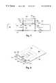
- FIG. 8is a perspective view of a circuit board that incorporates an accelerometer according to one embodiment of the invention.
- FIG. 9is a side view of the accelerometer portion of the circuit board of FIG. 8;
- FIG. 10is a perspective view of the circuit board of FIG. 8 wherein a shear damper is disposed on a beam of the accelerometer portion of the circuit board according to one embodiment of the invention
- FIG. 11is a perspective view of the circuit board of FIG. 8 wherein damping foam is disposed on a distal end of the beam of the accelerometer portion of the circuit board according to one embodiment of the invention
- FIGS. 12A-Bshow top and side views of a piezoceramic element typically used in a speaker or microphone that may be used to measure acceleration of an object in accordance with one embodiment of the invention
- FIG. 13illustrates how the piezoceramic element of FIGS. 12A-B may be mounted in a base so as to measure acceleration of the base in accordance with one embodiment of the invention.
- FIG. 14is a schematic diagram of a circuit in which a transducer used to monitor the flexing of a structure may be included in accordance with one embodiment of the invention.
- a structuree.g., a beam or a disk
- one side of the structureis subjected to compression forces and is caused to contract
- the opposite side of the structureis subjected to tension forces and is caused to expand.
- Prior art accelerometer devicesthat employ transducers made of piezoceramic materials, e.g., the acceleration-sensing devices of FIGS. 1 and 2, exploit this characteristic of flexible structures by using the flexible structures themselves to generate voltages indicative of amounts that the structures are flexed.
- the flexing of a flexible structureis monitored using a transducer that is attached to the flexible structure, rather than the flexible structure itself, to generate a signal indicative of the structure's flexing.
- the transducerwhen the flexible structure is attached to an object so that the structure flexes in response to acceleration of the object, the transducer generates a signal indicative of the object's acceleration.
- the transducer in such an embodimentmay be any of numerous devices or substances capable of monitoring one or more physical characteristics of the structure that change as the structure flexes, and may be supported by the flexible structure in any of a number of ways achieve this result.
- the inventionis not limited to any particular type of transducer, or to any particular device or technique for securing the transducer to the flexible structure.
- the flexible structure in such an embodimentmay take on any of numerous forms, and may be secured to the object in any of a number of ways so that the structure flexes when the object accelerates.
- the inventionis not limited to any particular type of structure or to any particular device or technique for securing the structure to the object whose acceleration is to be monitored.
- the term “transducer”refers to any device or substance that is capable of converting input energy of one form, e.g., physical energy, into output energy of another form, e.g., electrical energy.
- FIGS. 3A-Bshow an example of a flexible structure that may be secured to an object so that the structure flexes when the object is accelerated.
- the flexible structureis a beam 302 .
- the structuremay be primarily two-dimensional (i.e., substantially flat), and be of any shape such as triangular, square, rectangular, trapezoidal, rhombic, oval, round, or the like, or may be three-dimensional and have any number of flat or surfaces of these or different shapes.
- one or more portions of the beam 302may be secured to an object (not shown) whose acceleration is to be monitored so that the beam 302 is caused to flex when the object is accelerated.
- a first portion, e.g., end 306 , of the beam 302may be held by a support (not shown) that is attached to the object, and a second portion, e.g., end 310 , of the beam 302 may be left unsupported so that it can move with respect to the object when the object is accelerated.
- a first portion, e.g., middle portion 312 , of the beam 302may be secured to the object in some manner so that two second portions, e.g., the two free ends 308 and 310 , of the beam 302 are permitted to move with respect to the object when the object is accelerated.
- Other configurationsare also possible to achieve a similar result, and will be readily apparent to those skilled in the art.
- 3A-Bis shown as flexing only in a downward direction, it should be understood that the beam 302 (or other structure) may also be flexed upwards, sideways, or in any other direction, and that the same or similar measurable characteristic(s) as those described below may be monitored for changes in such situations.
- One characteristic of the flexible beam 302 that may be monitored for changes when the shape of the beam 302 is altered from its unflexed position (FIG. 3A) to its flexed position (FIG. 3B)is the length of a particular section of one of the top 304 and bottom surfaces 306 of the beam 302 . That is, when the beam 302 flexes (FIG. 3 B), the surface 304 on the expanding side of the beam 302 is elongated, and the surface 306 on the contracting side of beam 302 is shortened. As shown in FIG.
- the length L 0 across the middle portion of the beam 302is identical to the lengths L 1 and L 2 across the bottom and top surfaces 306 and 304 , respectively.
- the length L 0 across the middle portion of the beam 302remains the same, but the length is L 2 ′ across the top surface 304 increases and the length L 1 ′ across the bottom surface 306 decreases. Therefore, when the beam 302 is flexed, the length L 2 ′ is caused to be longer than the length L 0 , and the length L 1 ′ is caused to be shorter than the length L 0 . Examples of how transducers may be supported by the beam 302 so as to measure these dimensional changes on the top and bottom surfaces 304 and 306 are described below.
- dimensional changesalso take place internal to the beam 302 when the beam 302 flexes, and that, in alternative embodiments, such dimensional changes may be monitored by one or more properly placed transducers. However, the most significant dimensional changes occur on the top and bottom surfaces 304 and 306 of the beam 302 .
- Another characteristic of the flexible beam 302 that may be monitored for changes when the shape of the beam 302 is altered from its unflexed position (FIG. 3A) to its flexed position (FIG. 3B)is the amount of tension or compression that is exerted at a particular location within the beam. Therefore, in some embodiments, one or more transducers may be strategically placed within the beam 302 so as to measure stress changes within the beam 302 that occur when the beam 302 flexes.
- FIG. 3AYet another characteristic of the flexible beam 302 that may be monitored for changes when the shape of the beam 302 is altered from its unflexed position (FIG. 3A) to its flexed position (FIG. 3B) is the curvature of a particular section of one of the beam's surfaces.
- the changes in this characteristicare evident from a study of FIGS. 3A-B, and therefore will not be described further. Examples of how transducers may be supported by the beam 302 so as to measure the curvature changes of the top and bottom surfaces 304 and 306 of the beam 302 are described below.
- FIGS. 4A-Cshow an example of how a transducer 404 , e.g., a piezoceramic element, piezoresistive element, or the like, may be supported by a flexible structure, e.g., the beam 302 or any other suitable structure, so as to generate a signal responsive to changes in one or more characteristic of the structure that occur when the structure flexes. Therefore, when the beam 302 of the embodiment of FIGS. 4A-C is attached to an object (not shown) so that the beam 302 is caused to flex in response to acceleration of the object, the output of the transducer 404 is indicative of the acceleration of the object.
- a transducer 404e.g., a piezoceramic element, piezoresistive element, or the like
- a controller(not shorn) may be coupled to the transducer 404 to receive the output signal therefrom, and may monitor the signal to monitor the acceleration of the object.
- the term “controller”is intended to refer to any circuitry or component(s) used to monitor the signal from a transducer to monitor the acceleration of an object. The invention is not limited to the use of any particular type of controller to perform this monitoring function.
- the controller which is used to monitor the acceleration of the objectmay, for example, comprise a simple peak detection circuit. Alternatively, the controller used may comprise a microcontroller chip, or a personal computer, which receives the signal from the transducer.
- the transducer 404is supported by the beam 302 so as to monitor changes in a surface dimension of the beam 302 (i.e., a distance between locations 406 a and 406 b on a top surface 410 of the beam 302 ), as well as changes in the curvature of the top surface 410 , that occur when the beam 302 flexes.
- FIGS. 4 A-C(1) when the beam 302 is unflexed (FIG. 4 A), there is a distance D 2 between the locations 406 a and 406 b ; (2) when the beam 302 is flexed downward (FIG. 4 B), there is a distance D 2 ′ (which is longer than the distance D 2 ) between the locations 406 a and 406 b ; and ( 3 ) when the beam 302 is flexed upward (FIG. 4 C), there is a distance D 2 ′′ (which is shorter than the distance D 2 ) between the locations 406 a and 406 b .
- FIGS. 4 Awhen the beam 302 is unflexed (FIG. 4 A), there is a distance D 2 between the locations 406 a and 406 b ; (2) when the beam 302 is flexed downward (FIG. 4 B), there is a distance D 2 ′ (which is longer than the distance D 2 ) between the locations 406 a and 406 b ;
- supports 408 a and 408 be.g., metal or plastic members used to support the transducer 404 on the beam 302
- supports 408 a and 408 bare disposed on opposite ends of the transducer 404 and are fixedly secured to the locations 406 a and 406 b , respectively, so that the changes in the dimension D 2 that occur when the beam 302 flexes also cause the length D 3 of a lower portion 416 of the transducer 404 to change accordingly.
- the supports 408 a and 408 bwhen used, can take on any of numerous forms, and that the invention is not limited to any particular type of supports.
- FIGS. 4 A-C(1) when the beam 302 is unflexed (FIG. 4 A), the lower portion 416 of the transducer 404 has a length D 3 ; (2) when the beam 302 is flexed downward (FIG. 4 B), the lower portion 416 of the transducer 404 has a length D 3 ′ (which is longer than the length D 3 ); and (3) when the beam 302 is flexed upward (FIG. 4 C), the lower portion 416 of the transducer 404 has a length D 3 ′′ (which is shorter than the length D 3 ).
- the transducer 404 in the embodiment of FIGS. 4A-Ctherefore generates a signal responsive to such changes in the length D 3 of its lower portion 416 .
- the supports 408 a and 408 b and/or the transducer 404are constructed and arranged so that a bottom surface 412 of the transducer 404 is held in direct contact with the top surface 410 of the beam 302 when the beam 302 flexes.
- the supports 408 a and 408 bare rigid enough and are secured to the top surface 410 in such a manner that the physical relationship between each of the supports 408 a and 408 b and the top surface 410 of the beam 302 is not altered when the beam 302 flexes.
- This configurationforces the curvature of the bottom surface 412 of the transducer 404 to mimic the curvature of the top surface 410 of the beam 302 .
- an upper portion 414 of the transducer 404elongates from a length D 4 (FIG. 4A) to a length D 4 ′ (FIG. 4B) when the beam 302 is flexed downward, and shortens from the length D 4 (FIG. 4A) to a length D 4 ′′ (FIG. 4C) when the beam 302 is flexed upward. Therefore, in the embodiment of FIGS.
- the signal generated by the transducer 404also is responsive to changes in the length D 4 of its upper portion 414 that occur as a result of the curvature of the bottom surface 412 of the transducer 404 mimicking the curvature of the top surface 410 of the beam 302 .
- the curvature of the bottom surface 412 of the transducer 404may also be caused to mimic the curvature of the top surface 410 of the beam 302 in a number of other ways.
- the entire bottom surface 412 of the transducer 404may be fixedly secured, e.g., using an adhesive, to the top surface 410 to achieve such a result.
- the supports 408 a and 408 bmay or may not also be used to secure the transducer 404 to the top surface 410 .
- FIGS. 5A-Cshow another example of how a transducer 404 , e.g., a piezoceramic element, a piezoresistive element, or the like, may be supported by a flexible structure, e.g., the beam 302 or another suitable structure, so as to generate a signal responsive to changes in one or more characteristic of the structure that occur when the structure flexes. Therefore, when the beam 302 of the embodiment of FIGS. 5A-C is attached to an object (not shown) so that the beam. 302 is caused to flex in response to acceleration of the object, the output of the transducer 404 is indicative of the acceleration of the object.
- a transducer 404e.g., a piezoceramic element, a piezoresistive element, or the like
- a controllermay be coupled to the transducer 404 to receive the output signal therefrom, and may monitor the signal to monitor the acceleration of the object.
- the transducer 404primarily monitors changes in a surface dimension of the beam 302 , i.e., a distance between the locations 406 a and 406 b on the top surface 410 of the beam 302 .
- the transducer 404may be secured to the locations 406 a and 406 b on the top surface 410 of the beam 302 using the supports 408 a and 408 b , respectively, so that a gap 502 is formed between the bottom surface 412 of the transducer 404 and the top surface 410 of the beam 302 .
- the supports 408 a and 408 bare made of a material that is flexible enough that the supports 408 a and 408 b are allowed to deform slightly when the beam 302 flexes.
- the curvature of the transducer 404is not altered significantly, but the transducer 404 is elongated or shortened in the directions indicated by the arrows in FIGS. 5B and 5C.
- the beam 302flexes upward (FIG.
- the amplitude of the voltage generated by the transducer 404is affected primarily by the stretching and compression forces exerted on the ends of the transducer 404 , and is affected only secondarily, if at all, by any bending forces exerted thereon.
- a relatively small transducer 404may be mounted on a beam 302 (or another structure) having a relatively large surface area so that the transducer 404 covers only a small portion (e.g., one fourth, one tenth, one one-hundredth, or even one one-thousandth) of the surface area of the beam 302 .
- the flexibility of the beam 302may not be affected substantially by the presence of the transducer 404 thereon, and the,e flexibility of the unit including both the transducer 404 and the beam 302 is determined primarily by the flexibility of the beam 302 . It should be appreciated that a similar result may also be accomplished in other ways.
- a transducer 404may be employed which is substantially more flexible that the beam 302 (or another structure) on which it is mounted.
- the effect that each of a transducer 404 and a beam 302 (or another structure) has on the flexibility of a unit including both elementscan be appreciated by examining the position of the so-called neutral axis (explained below) of the unit which passes through the unit when the unit flexes.
- FIGS. 6A-Cillustrate an example of how a flexible structure (e.g., the beam 302 ) and one or more transducers 404 a-b may be configured and arranged such that mounting of each transducer 404 on the beam 302 does not substantially affect the position of a neutral axis 418 which passes through a unit 600 (including both the beam 302 and the transducer(s) 404 ) when the unit 600 is flexed.
- the neutral axis 418 of the unit 600is the axis that (when the unit 600 is flexed) separates the portion 602 of the unit 600 that is subjected to tension forces from the portion 604 of the unit 600 that is subjected to compression forces.
- the location of the neutral axis 418may be affected, for example, by the relative sizes, positions, and flexibilities of the beam 302 and the transducer(s) 404 , and/or the manner in which such elements are interconnected.
- the position of the neutral axis 418 of the unit 600is located at substantially the same location: (a) when both of the transducers 404 a and 404 b are attached to the beam 302 (FIG. 6 A); (b) when only the transducer 404 b is attached to the beam 302 (FIG. 6 B); and (c) when neither of the transducers 404 a and 404 b is attached to the beam 302 (FIG. 6 C). Therefore, the attachment or removal of either (FIG. 6B) or both (FIG.
- the neutral axis 418passes only through the beam 302 , and does not pass trough either of the transducers 404 a and 404 b , regardless of whether either or both of the transducers 404 a and 404 b are attached to the beam 302 . It should be understood that the other embodiments of the invention described herein may also incorporate this aspect of the invention. For example, in each of FIGS.
- the transducer 404 and the beam 302may be constructed and arranged such that the position of the neutral axis 418 passes only through the beam 302 , regardless of whether the transducer 404 is mounted thereto.
- FIG. 7shows an example of how a specific type of transducer, i.e., a multi-layer capacitor 708 having a piezoceramic dielectric 706 , may be attached to a specific type of flexible structure, i.e., a section 710 of an organic-laminate circuit board material, so as to generate a signal responsive to changes in a specific characteristic of the circuit board section 710 (i.e., a distance between locations 706 a and 706 b on the circuit board's top surface 712 ) that occur when the circuit board section 710 flexes.
- a specific type of transduceri.e., a multi-layer capacitor 708 having a piezoceramic dielectric 706
- a specific type of flexible structurei.e., a section 710 of an organic-laminate circuit board material
- the piezoceramic dielectric 706 of the capacitor 708may generate a signal between pole conductors 714 a-b of the capacitor 708 when it is compressed and/or stretched as the circuit board section 710 flexes. Therefore, when the circuit board section 710 is attached to an object (not shown) so that the circuit board section 710 is caused to flex in response to acceleration of the object, the signal generated between the pole conductors 714 a and 714 b of the capacitor 708 is indicative of the acceleration of the object.
- a controller(not shown) may be coupled to the capacitor 708 to receive the output signal therefrom, and may monitor the signal to monitor the acceleration of the object.
- a capacitor suitable for use as the capacitor 708 in the FIG. 7 embodimentmay, for example, be selected from the GRM series of monolithic ceramic capacitors available from Murata Electronics Distributors. Such capacitors are on the order of two millimeters (mm) long, one millimeter wide, and one millimeter thick, and may be mass-produced at a very low cost (e.g, one-tenth of one cent each). It should be appreciated, of course, that other capacitors having the desired piezoelectric characteristics may alternatively be,used, and that the invention is not limited to the particular type of capacitor shown and described.
- each of the plates P 1 and P 2 of the capacitor 708may include multiple layers of conductors P 1 A-P 1 C and P 2 A-P 2 B, with the conductors P 1 A-P 1 C of one plate p 1 being interdigitated with the conductors P 2 A-P 2 B of the other plate P 2 . While the capacitor 708 of FIG.
- the capacitor 7may function satisfactorily in the form in which it is originally produced by its manufacturer, it may be desirable to prepolarize the piezoceramic dielectric 706 of the capacitor 708 by placing a high, but non-destructive voltage (e.g., just below the capacitor's maximum voltage rating) between the capacitor's plates while maintaining the capacitor 708 at a temperature just below the Curie point of its ceramic dielectric 706 .
- a high, but non-destructive voltagee.g., just below the capacitor's maximum voltage rating
- the circuit board section 710 of the FIG. 7 embodimentmay be made of any of numerous types of materials, and the invention in not limited to any particular type of circuit board material.
- the circuit board section 710is a section of an organic-laminate substrate.
- such a circuit boardis considered to be a “no-conductive” structure, even though it may have electrically conductive circuit traces and/or power/ground planes thereon or therein which may or may not be coupled to the capacitor 710 or other transducer used therewith to monitor acceleration.
- the pole conductors 714 a-b of the capacitor 708electrically connect the plates P 1 and P 2 of the capacitor 708 to conductors 704 of the circuit board.
- the pole conductors 714 a-bare inserted into vias 702 in the circuit board and are soldered therein so as to make electrical contact with the conductors 704 .
- the pole conductors 714 a-bmay be pins of a surface-mounted device.
- the circuit traces 704 in the FIG. 7 embodimentmay be electrically connected to other components in a circuit in which the capacitor 708 is included so that the capacitor 708 is electrically coupled to such components.
- the characteristics of the capacitor 708 and the circuit board section 710 , and the physical relationships therebetween,may be similar to the characteristics of and physical relationships between, the beams 302 or other surfaces and the transducers 404 used therewith discussed above in connection with FIGS. 4-6.
- the relative flexibilities of the circuit board section 710 and the capacitor 708are such that the neutral axis of the combination passes through the circuit board section 710 regardless of whether the capacitor 708 is attached thereto.
- FIGS. 8 and 9show perspective and side views, respectively, of an illustrative embodiment of the invention wherein a transducer 404 (e.g., a capacitor having a piezoceramic dielectric such as that described in connection with FIG. 7) is mounted on a section 710 of a circuit board 802 .
- the circuit board 802also includes a section 816 on which additional circuitry 804 is disposed.
- Such a structuremay be formed, for example, by cutting or otherwise establishing a gap or slit 820 in the circuit board 802 , or by prefabricating the circuit board 802 to include the beam-like section 710 .
- a distal end 812 of the circuit board section 710is permitted to move when the section 816 of the circuit board 802 (or an object to which the section 816 is mounted) is accelerated.
- FIGS. 8 and 9employs a circuit board 802 that includes separate beam-like 710 and circuitry 816 sections
- the portion 816 of the circuit board 802 that has the additional circuitry 804 mounted thereonmay itself be used as a structure whose flexing is to be monitored.
- the circuit board (or other structure) whose flexing is to be monitoredmay, for example, be rectangular, circular, or any other shape.
- a pair of notches 808 a and 808 bare formed on the sides 818 a and 818 b of the circuit board section 710 near a location 810 along a longitudinal axis of the circuit board section 710 at which the transducer 404 is mounted.
- This placement of the notches 808 a and 808 bmake the circuit board section 710 more narrow, and therefore more flexible, at the location 810 than at other locations along the circuit board section's longitudinal axis.
- inclusion of the notches 808 a and 808 b in the circuit board section 710causes the circuit board section 710 to flex primarily at the location 810 when the section 816 of the circuit board 802 (or an object to which the section 816 is mounted) is accelerated. It should be appreciated, however, that the circuit boardsection 710 may be caused to flex primarily at the location 810 in alternative ways, and that the invention is not limited to the use of notches in the circuit board section 710 to cause such a result.
- a different thickness and/or type of materialmay be used to form a portion of the circuit board section 710 at the location 810 than is used to form the remainder of the circuit board section 710 , or the portion of the circuit board section 710 at the location 810 may otherwise be physically or chemically altered or weakened so as to make that portion 810 more flexible than the remainder of the circuit board section 710 .
- a weight 806is disposed on the distal end 812 of the circuit board section 710 to increase a moment force that is applied about a proximal end 814 of the circuit board section 710 when the section 816 of the circuit board 802 (or an object to which the section 810 to attached) is accelerated.
- This placement of the weight 806therefore increases the sensitivity of the accelerometer.
- the sensitivity of the accelerometer of FIGS. 8 and 9may also be increased or decreased by adjusting the length of the circuit board section 710 or by altering its flexibility.
- a pair of transducers 404 a and 404 bare mounted on opposite sides of the circuit board section 710 so that, whenever the bending of the circuit board section 710 causes one of the transducers 404 a and 404 b to be stretched, the other transducer 404 is compressed a corresponding amount, and vice versa.
- the transducers 404 a and 404 b togethercan generate a differential signal indicative of the acceleration of the portion 816 circuit board 802 (or an object to which the section 816 is attached).
- FIG. 10shows how the embodiment of FIGS. 8 and 9 may be modified by disposing a shear damper 1002 on a top surface of the circuit board section 710 .
- the shear damper 1002may, for example, be made of a material (e.g., plastic, metal, glass, fiberglass, or the like) that is substantially more rigid than the circuit board section 710 .
- the use of such a shear dampermay, for example, reduce the vibration of the circuit board section 710 , and/or cause the circuit board section 710 to flex primarily at the location 810 when the section 816 of the circuit board 802 (or an object to which the section 816 is attached) is accelerated.
- shear damper 1002 of a particular shapei.e., the same shape as the circuit board section 710
- devices of other shapeswhich also are capable of dampening the shear of the circuit board section 710 may alternatively be employed, and that the invention is not limited to the particular shape of shear damper shown.
- additional shear dampersmay also be disposed on the circuit board section 710 , e.g., one on each side, and that the invention is not limited to the use of a single shear dampening device.
- FIG. 11illustrates how the embodiments of FIGS. 8-10 may be modified by disposing a masse of damping foam 1102 , or the like, on the distal end 812 of the circuit board section 710 .
- an opening 1104 in the damping foam 1102surrounds the distal end 812 and the weight 806 such that inner surfaces 1106 and 1108 of the damping foam 1102 exert compression forces on the weight 806 and the distal end 812 to hold the damping foam 1102 in place on the distal end 812 of the circuit board section 710 .
- the damping foam 1102may, for example, be placed near or in contact with a casing (not shown) in which the circuit board 802 is disposed.
- the damping foam 1102may contact the casing when the distal end 812 of the circuit board section 710 moves, and thereby dampen the motion of the distal end 812 .
- the use of the damping foam 1102 , or the like, in this mannermay, for example, reduce the ringing in the signal output by the transducer 404 .
- a disk-shaped elementincluding a piezoelectric transducer or the like
- a disk-shaped elementmay be used to monitor acceleration of an object by properly mounting the element to the object and monitoring a signal output by the transducer included therein.
- Top and side-views of an example embodiment of a disk-shaped element 1200 that may be used for this purposeare shown in FIGS. 12A-B, respectively.
- An example of one such disk-shaped elementis part number CD 11 BB, manufactured by Taiyo Yuden. In the example shown in FIGS.
- the disk-shaped element 1200includes a flat, disk-shaped metal support 1202 , and a flat, disk-shaped section of piezoceramic material 1210 concentrically arranged on a top surface 1204 of the support disk 1202 .
- conductors 1206 a-bmay be connected, respectively, to a top surface 1208 of the piezoceramic disk 1210 and to a portion 1212 of the conductive support disk 1202 .
- FIG. 13illustrates an example of how the disk-shaped element 1200 of FIG. 12 may be supported by a base 1302 (i.e., an object whose acceleration is to be monitored) so that a signal generated between the conductors 1206 a-b of the element 1200 is indicative of the acceleration of the base 1302 (the object).
- a base 1302i.e., an object whose acceleration is to be monitored
- an outer portion 1310 of the support disk 1202is secured to (e.g., using an epoxy or other substance or technique) a circular shelf 1306 of the base 1302 .
- a cylindrical ledge 1312drops off from the circular shelf 1306 to form a cavity 1308 within the base 1302 .
- the support disk 1202When the base 1302 (the object) is accelerated, the support disk 1202 is caused to flex such that a center portion 1304 of the support disk 1202 is caused to move up and down within the cavity 1308 of the base, 1302 (as indicated by the arrows in FIG. 13 ). Because the piezoceramic disk 1210 generates a signal in response to the flexing of the support disk 1202 , the signal generated between the conductors 1206 a-b when the base 1302 (the object) is accelerated is indicative of the acceleration of the base 1302 .
- a controller(not shown) may be coupled to the conductors 1206 to receive the output signal therefrom, and may monitor the signal to monitor the acceleration of the base 1302 .
- the characteristics of the piezoceramic disk 1210 and the support disk 1202 , and the physical relationships therebetween,may be similar to the characteristics of, and the physical relationships between, the beams 302 or other surfaces and the transducers 404 used therewith discussed above in connection with FIGS. 4-6.
- the relative flexibilities of the support disk 1202 and the piezoceramic disk 1210may be such that the neutral axis of the combination passes through the support disk 1202 regardless of whether the piezoceramic disk 1210 is attached thereto.
- FIG. 14is a schematic diagram showing an illustrative embodiment of an electronic circuit 1400 in which an element 1406 used as a transducer to monitor the flexing or other characteristics of a structure in response to acceleration of an object to which the structure is attached may be included.
- the element 1406may correspond, for example, to the transducer 404 of FIGS. 4-6 and 7 - 11 , to the capacitor 708 of FIG. 7, or the disk-shaped element 1200 of FIGS. 12 and 13.
- the components in the circuit 1400(other than the element 1406 ) may, for example, be included in the additional circuitry 804 shown in FIGS. 8, 10 , and 11 .
- FIG. 8the additional circuitry 804 shown in FIGS. 8, 10 , and 11 .
- the element 1406has a well-defined capacitance associated therewith (e.g., it may be a capacitor having a piezoceramic or another piezoelectric dielectric), and is therefore used as a capacitor C 1 in the circuit 1400 , in addition to being used as a transducer.
- the circuit 1400additionally includes an amplifier 1402 , a controller 1404 , capacitors C 2 -C 5 , and resistors R 1 -R 5 .
- the amplifier 1402is coupled to the element 1406 to receive and amplify a signal generated thereby.
- the controller 1404 in the embodiment shownmay, for example, include a microprocessor which includes an on-board analog-to-digital converter.
- the controller 1404 in such an embodimentmay, for example, convert the output of the amplifier 1402 into a digital signal and analyze the digital signal to monitor the acceleration of an object.
- the purpose and function of each of the other componentswill be readily understood to one skilled in the art, and therefore will not be discussed further.
- circuit 1400When the circuit 1400 is disposed on a circuit board (e.g., the circuit board 802 of FIGS. 8, 10 , and 11 ) such that the element 1406 generates a signal responsive to flexing of the circuit board (or a portion thereof), the element 1406 and circuit board together function as an accelerometer. Therefore, any circuit board may conceivably be modified to sense acceleration of an object to which it is attached simply by properly placing a transducer on the circuit board so as to generate a signal responsive to the flexing of the circuit board.
- a circuit boarde.g., the circuit board 802 of FIGS. 8, 10 , and 11
- any circuit boardmay conceivably be modified to sense acceleration of an object to which it is attached simply by properly placing a transducer on the circuit board so as to generate a signal responsive to the flexing of the circuit board.
Landscapes
- Physics & Mathematics (AREA)
- General Physics & Mathematics (AREA)
- Electromagnetism (AREA)
- Engineering & Computer Science (AREA)
- Microelectronics & Electronic Packaging (AREA)
- Pressure Sensors (AREA)
- Transmission And Conversion Of Sensor Element Output (AREA)
Abstract
Description
Claims (62)
Priority Applications (13)
| Application Number | Priority Date | Filing Date | Title |
|---|---|---|---|
| US09/382,049US6336365B1 (en) | 1999-08-24 | 1999-08-24 | Low-cost accelerometer |
| US09/643,191US6898550B1 (en) | 1997-10-02 | 2000-08-21 | Monitoring activity of a user in locomotion on foot |
| US09/643,188US6876947B1 (en) | 1997-10-02 | 2000-08-21 | Monitoring activity of a user in locomotion on foot |
| AU80333/00AAU8033300A (en) | 1999-08-24 | 2000-08-24 | Low-cost accelerometer |
| PCT/US2000/040729WO2001014889A2 (en) | 1999-08-24 | 2000-08-24 | Low-cost accelerometer |
| US11/098,788US7200517B2 (en) | 1997-10-02 | 2005-04-04 | Monitoring activity of a user in locomotion on foot |
| US11/588,589US7428471B2 (en) | 1997-10-02 | 2006-10-27 | Monitoring activity of a user in locomotion on foot |
| US11/706,150US7428472B2 (en) | 1997-10-02 | 2007-02-13 | Monitoring activity of a user in locomotion on foot |
| US11/706,144US7617071B2 (en) | 1997-10-02 | 2007-02-13 | Monitoring activity of a user in locomotion on foot |
| US12/571,392US7962312B2 (en) | 1997-10-02 | 2009-09-30 | Monitoring activity of a user in locomotion on foot |
| US13/158,984US8712725B2 (en) | 1997-10-02 | 2011-06-13 | Monitoring activity of a user in locomotion on foot |
| US14/243,675US9247897B2 (en) | 1997-10-02 | 2014-04-02 | Monitoring activity of a user in locomotion on foot |
| US14/993,900US20160120414A1 (en) | 1997-10-02 | 2016-01-12 | Monitoring Activity of a User in Locomotion on Foot |
Applications Claiming Priority (1)
| Application Number | Priority Date | Filing Date | Title |
|---|---|---|---|
| US09/382,049US6336365B1 (en) | 1999-08-24 | 1999-08-24 | Low-cost accelerometer |
Related Parent Applications (3)
| Application Number | Title | Priority Date | Filing Date |
|---|---|---|---|
| US09/164,654Continuation-In-PartUS6122340A (en) | 1997-10-02 | 1998-10-01 | Detachable foot mount for electronic device |
| US09/364,559Continuation-In-PartUS6052654A (en) | 1997-10-02 | 1999-07-30 | Measuring foot contact time and foot loft time of a person in locomotion |
| US09/521,073Continuation-In-PartUS6560903B1 (en) | 1997-10-02 | 2000-03-07 | Ambulatory foot pod |
Related Child Applications (4)
| Application Number | Title | Priority Date | Filing Date |
|---|---|---|---|
| US09/164,654Continuation-In-PartUS6122340A (en) | 1997-10-02 | 1998-10-01 | Detachable foot mount for electronic device |
| US09/521,073Continuation-In-PartUS6560903B1 (en) | 1997-10-02 | 2000-03-07 | Ambulatory foot pod |
| US09/643,188Continuation-In-PartUS6876947B1 (en) | 1997-10-02 | 2000-08-21 | Monitoring activity of a user in locomotion on foot |
| US09/643,191Continuation-In-PartUS6898550B1 (en) | 1997-10-02 | 2000-08-21 | Monitoring activity of a user in locomotion on foot |
Publications (1)
| Publication Number | Publication Date |
|---|---|
| US6336365B1true US6336365B1 (en) | 2002-01-08 |
Family
ID=23507341
Family Applications (1)
| Application Number | Title | Priority Date | Filing Date |
|---|---|---|---|
| US09/382,049Expired - LifetimeUS6336365B1 (en) | 1997-10-02 | 1999-08-24 | Low-cost accelerometer |
Country Status (3)
| Country | Link |
|---|---|
| US (1) | US6336365B1 (en) |
| AU (1) | AU8033300A (en) |
| WO (1) | WO2001014889A2 (en) |
Cited By (203)
| Publication number | Priority date | Publication date | Assignee | Title |
|---|---|---|---|---|
| US6860954B2 (en)* | 1998-12-09 | 2005-03-01 | Taiyo Yuden Co., Ltd. | Circuit board having thereon coupled ceramic capacitors and method for the manufacture thereof |
| US20050183292A1 (en)* | 2003-03-10 | 2005-08-25 | Christian Dibenedetto | Intelligent footwear systems |
| US20060088228A1 (en)* | 2004-10-25 | 2006-04-27 | Apple Computer, Inc. | Image scaling arrangement |
| US20060153040A1 (en)* | 2005-01-07 | 2006-07-13 | Apple Computer, Inc. | Techniques for improved playlist processing on media devices |
| US20060274905A1 (en)* | 2005-06-03 | 2006-12-07 | Apple Computer, Inc. | Techniques for presenting sound effects on a portable media player |
| US20060283050A1 (en)* | 2005-03-31 | 2006-12-21 | Adidas International Marketing B.V. | Shoe housing |
| US20070000154A1 (en)* | 2003-03-10 | 2007-01-04 | Christian Dibenedetto | Intelligent footwear systems |
| US20070011920A1 (en)* | 2003-03-10 | 2007-01-18 | Adidas International Marketing B.V. | Intelligent footwear systems |
| US20070088806A1 (en)* | 2005-10-19 | 2007-04-19 | Apple Computer, Inc. | Remotely configured media device |
| US20070157268A1 (en)* | 2006-01-05 | 2007-07-05 | Apple Computer, Inc. | Portable media device with improved video acceleration capabilities |
| US20070156962A1 (en)* | 2006-01-03 | 2007-07-05 | Apple Computer, Inc. | Media device with intelligent cache utilization |
| US20070161402A1 (en)* | 2006-01-03 | 2007-07-12 | Apple Computer, Inc. | Media data exchange, transfer or delivery for portable electronic devices |
| US20070201703A1 (en)* | 2006-02-27 | 2007-08-30 | Apple Computer, Inc. | Dynamic power management in a portable media delivery system |
| US20070208911A1 (en)* | 2001-10-22 | 2007-09-06 | Apple Inc. | Media player with instant play capability |
| US20070234420A1 (en)* | 2004-04-27 | 2007-10-04 | Novotney Donald J | Method and system for authenticating an accessory |
| US20070271387A1 (en)* | 2006-05-22 | 2007-11-22 | Apple Computer, Inc. | Communication protocol for use with portable electronic devices |
| US20070271065A1 (en)* | 2006-05-22 | 2007-11-22 | Apple Computer, Inc. | Portable media device with workout support |
| US20070271116A1 (en)* | 2006-05-22 | 2007-11-22 | Apple Computer, Inc. | Integrated media jukebox and physiologic data handling application |
| US20070270663A1 (en)* | 2006-05-22 | 2007-11-22 | Apple Computer, Inc. | System including portable media player and physiologic data gathering device |
| US20080057890A1 (en)* | 2006-08-30 | 2008-03-06 | Apple Computer, Inc. | Automated pairing of wireless accessories with host devices |
| US20080065246A1 (en)* | 2006-09-11 | 2008-03-13 | Apple Inc. | Highly portable media devices |
| US20080065988A1 (en)* | 2006-09-11 | 2008-03-13 | Apple Computer, Inc. | Portable electronic device with local search capabilities |
| US20080070501A1 (en)* | 2006-08-30 | 2008-03-20 | Apple Computer, Inc. | Pairing of wireless devices using a wired medium |
| US20080125890A1 (en)* | 2006-09-11 | 2008-05-29 | Jesse Boettcher | Portable media playback device including user interface event passthrough to non-media-playback processing |
| US20080139953A1 (en)* | 2006-11-01 | 2008-06-12 | Welch Allyn, Inc. | Body worn physiological sensor device having a disposable electrode module |
| US20080204218A1 (en)* | 2007-02-28 | 2008-08-28 | Apple Inc. | Event recorder for portable media device |
| US20080218310A1 (en)* | 2007-03-07 | 2008-09-11 | Apple Inc. | Smart garment |
| US20080262392A1 (en)* | 2006-05-22 | 2008-10-23 | Apple Inc. | Calibration techniques for activity sensing devices |
| US20090013253A1 (en)* | 2006-09-11 | 2009-01-08 | Apple Inc. | Method and system for controlling video selection and playback in a portable media player |
| US20090048070A1 (en)* | 2007-08-17 | 2009-02-19 | Adidas International Marketing B.V. | Sports electronic training system with electronic gaming features, and applications thereof |
| US20090077800A1 (en)* | 2007-09-24 | 2009-03-26 | Randall Michael S | Method of attaching an electronic device to an mlcc having a curved surface |
| US20090083834A1 (en)* | 2005-01-07 | 2009-03-26 | Apple Inc. | Accessory authentication for electronic devices |
| US20090132076A1 (en)* | 2006-06-27 | 2009-05-21 | Apple Inc. | Method and system for allowing a media player to determine if it supports the capabilities of an accessory |
| US7590772B2 (en) | 2005-08-22 | 2009-09-15 | Apple Inc. | Audio status information for a portable electronic device |
| US20090249101A1 (en)* | 2006-09-11 | 2009-10-01 | Apple Inc. | Method and system for controlling power provided to an accessory |
| US20090266595A1 (en)* | 2008-04-28 | 2009-10-29 | Tdk Corporation | Electronic device |
| US20100063778A1 (en)* | 2008-06-13 | 2010-03-11 | Nike, Inc. | Footwear Having Sensor System |
| US20100075604A1 (en)* | 2008-09-08 | 2010-03-25 | Apple Inc. | Accessory device authentication |
| US7706637B2 (en) | 2004-10-25 | 2010-04-27 | Apple Inc. | Host configured for interoperation with coupled portable media player device |
| US20100173673A1 (en)* | 2008-09-08 | 2010-07-08 | Apple Inc. | Cross-transport authentication |
| US20100222165A1 (en)* | 2004-09-17 | 2010-09-02 | Adidas International Marketing B.V. | Bladder |
| EP2312420A1 (en) | 2006-09-28 | 2011-04-20 | Nike International Ltd | Sensor device with persistent low power beacon |
| US20110153219A1 (en)* | 2009-12-23 | 2011-06-23 | Fernihough Robert A P | Direct velocity seismic sensing |
| US20110199393A1 (en)* | 2008-06-13 | 2011-08-18 | Nike, Inc. | Foot Gestures for Computer Input and Interface Control |
| US8151259B2 (en) | 2006-01-03 | 2012-04-03 | Apple Inc. | Remote content updates for portable media devices |
| US8162804B2 (en) | 2007-02-14 | 2012-04-24 | Nike, Inc. | Collection and display of athletic information |
| US8358273B2 (en) | 2006-05-23 | 2013-01-22 | Apple Inc. | Portable media device with power-managed display |
| US8360904B2 (en) | 2007-08-17 | 2013-01-29 | Adidas International Marketing Bv | Sports electronic training system with sport ball, and applications thereof |
| US8386680B2 (en) | 2004-04-27 | 2013-02-26 | Apple Inc. | Communication between an accessory and a media player with multiple protocol versions and extended interface lingo |
| US8402187B2 (en) | 2004-04-27 | 2013-03-19 | Apple Inc. | Method and system for transferring button status information between a media player and an accessory |
| US8654993B2 (en) | 2005-12-07 | 2014-02-18 | Apple Inc. | Portable audio device providing automated control of audio volume parameters for hearing protection |
| US20140060911A1 (en)* | 2012-08-30 | 2014-03-06 | Allison Transmission, Inc. | Method and system for reducing audible and/or electrical noise from electrically or mechanically excited capacitors |
| US8702430B2 (en) | 2007-08-17 | 2014-04-22 | Adidas International Marketing B.V. | Sports electronic training system, and applications thereof |
| US8739639B2 (en) | 2012-02-22 | 2014-06-03 | Nike, Inc. | Footwear having sensor system |
| US8892446B2 (en) | 2010-01-18 | 2014-11-18 | Apple Inc. | Service orchestration for intelligent automated assistant |
| EP2843421A1 (en)* | 2013-08-29 | 2015-03-04 | PGS Geophysical AS | Piezoelectric accelerometer |
| US8990022B2 (en) | 2009-12-23 | 2015-03-24 | Pgs Geophysical As | Direct velocity seismic sensing |
| US9089182B2 (en) | 2008-06-13 | 2015-07-28 | Nike, Inc. | Footwear having sensor system |
| US9192816B2 (en) | 2011-02-17 | 2015-11-24 | Nike, Inc. | Footwear having sensor system |
| US9257054B2 (en) | 2012-04-13 | 2016-02-09 | Adidas Ag | Sport ball athletic activity monitoring methods and systems |
| US9262612B2 (en) | 2011-03-21 | 2016-02-16 | Apple Inc. | Device access using voice authentication |
| US9279734B2 (en) | 2013-03-15 | 2016-03-08 | Nike, Inc. | System and method for analyzing athletic activity |
| US9300784B2 (en) | 2013-06-13 | 2016-03-29 | Apple Inc. | System and method for emergency calls initiated by voice command |
| US9330720B2 (en) | 2008-01-03 | 2016-05-03 | Apple Inc. | Methods and apparatus for altering audio output signals |
| US9338493B2 (en) | 2014-06-30 | 2016-05-10 | Apple Inc. | Intelligent automated assistant for TV user interactions |
| US9368114B2 (en) | 2013-03-14 | 2016-06-14 | Apple Inc. | Context-sensitive handling of interruptions |
| US9381420B2 (en) | 2011-02-17 | 2016-07-05 | Nike, Inc. | Workout user experience |
| US9389057B2 (en) | 2010-11-10 | 2016-07-12 | Nike, Inc. | Systems and methods for time-based athletic activity measurement and display |
| US9411940B2 (en) | 2011-02-17 | 2016-08-09 | Nike, Inc. | Selecting and correlating physical activity data with image data |
| US9430463B2 (en) | 2014-05-30 | 2016-08-30 | Apple Inc. | Exemplar-based natural language processing |
| US9483461B2 (en) | 2012-03-06 | 2016-11-01 | Apple Inc. | Handling speech synthesis of content for multiple languages |
| US9495129B2 (en) | 2012-06-29 | 2016-11-15 | Apple Inc. | Device, method, and user interface for voice-activated navigation and browsing of a document |
| US9502031B2 (en) | 2014-05-27 | 2016-11-22 | Apple Inc. | Method for supporting dynamic grammars in WFST-based ASR |
| US9500464B2 (en) | 2013-03-12 | 2016-11-22 | Adidas Ag | Methods of determining performance information for individuals and sports objects |
| US9504414B2 (en) | 2012-04-13 | 2016-11-29 | Adidas Ag | Wearable athletic activity monitoring methods and systems |
| US9535906B2 (en) | 2008-07-31 | 2017-01-03 | Apple Inc. | Mobile device having human language translation capability with positional feedback |
| US9549585B2 (en) | 2008-06-13 | 2017-01-24 | Nike, Inc. | Footwear having sensor system |
| US9576574B2 (en) | 2012-09-10 | 2017-02-21 | Apple Inc. | Context-sensitive handling of interruptions by intelligent digital assistant |
| US9582608B2 (en) | 2013-06-07 | 2017-02-28 | Apple Inc. | Unified ranking with entropy-weighted information for phrase-based semantic auto-completion |
| US9620105B2 (en) | 2014-05-15 | 2017-04-11 | Apple Inc. | Analyzing audio input for efficient speech and music recognition |
| US9620104B2 (en) | 2013-06-07 | 2017-04-11 | Apple Inc. | System and method for user-specified pronunciation of words for speech synthesis and recognition |
| US9626955B2 (en) | 2008-04-05 | 2017-04-18 | Apple Inc. | Intelligent text-to-speech conversion |
| US9633660B2 (en) | 2010-02-25 | 2017-04-25 | Apple Inc. | User profiling for voice input processing |
| US9633004B2 (en) | 2014-05-30 | 2017-04-25 | Apple Inc. | Better resolution when referencing to concepts |
| US9633674B2 (en) | 2013-06-07 | 2017-04-25 | Apple Inc. | System and method for detecting errors in interactions with a voice-based digital assistant |
| US9646609B2 (en) | 2014-09-30 | 2017-05-09 | Apple Inc. | Caching apparatus for serving phonetic pronunciations |
| US9642415B2 (en) | 2011-02-07 | 2017-05-09 | New Balance Athletics, Inc. | Systems and methods for monitoring athletic performance |
| US9646614B2 (en) | 2000-03-16 | 2017-05-09 | Apple Inc. | Fast, language-independent method for user authentication by voice |
| US9668121B2 (en) | 2014-09-30 | 2017-05-30 | Apple Inc. | Social reminders |
| US9697820B2 (en) | 2015-09-24 | 2017-07-04 | Apple Inc. | Unit-selection text-to-speech synthesis using concatenation-sensitive neural networks |
| US9694247B2 (en) | 2013-02-15 | 2017-07-04 | Adidas Ag | Ball for a ball sport |
| US9697822B1 (en) | 2013-03-15 | 2017-07-04 | Apple Inc. | System and method for updating an adaptive speech recognition model |
| US9711141B2 (en) | 2014-12-09 | 2017-07-18 | Apple Inc. | Disambiguating heteronyms in speech synthesis |
| US9710711B2 (en) | 2014-06-26 | 2017-07-18 | Adidas Ag | Athletic activity heads up display systems and methods |
| US9715875B2 (en) | 2014-05-30 | 2017-07-25 | Apple Inc. | Reducing the need for manual start/end-pointing and trigger phrases |
| US9721566B2 (en) | 2015-03-08 | 2017-08-01 | Apple Inc. | Competing devices responding to voice triggers |
| US9734193B2 (en) | 2014-05-30 | 2017-08-15 | Apple Inc. | Determining domain salience ranking from ambiguous words in natural speech |
| US9737261B2 (en) | 2012-04-13 | 2017-08-22 | Adidas Ag | Wearable athletic activity monitoring systems |
| US9743861B2 (en) | 2013-02-01 | 2017-08-29 | Nike, Inc. | System and method for analyzing athletic activity |
| US9747248B2 (en) | 2006-06-20 | 2017-08-29 | Apple Inc. | Wireless communication system |
| US9760559B2 (en) | 2014-05-30 | 2017-09-12 | Apple Inc. | Predictive text input |
| US9756895B2 (en) | 2012-02-22 | 2017-09-12 | Nike, Inc. | Footwear having sensor system |
| US9763489B2 (en) | 2012-02-22 | 2017-09-19 | Nike, Inc. | Footwear having sensor system |
| US9785630B2 (en) | 2014-05-30 | 2017-10-10 | Apple Inc. | Text prediction using combined word N-gram and unigram language models |
| US9798393B2 (en) | 2011-08-29 | 2017-10-24 | Apple Inc. | Text correction processing |
| US9818400B2 (en) | 2014-09-11 | 2017-11-14 | Apple Inc. | Method and apparatus for discovering trending terms in speech requests |
| US9842105B2 (en) | 2015-04-16 | 2017-12-12 | Apple Inc. | Parsimonious continuous-space phrase representations for natural language processing |
| US9842101B2 (en) | 2014-05-30 | 2017-12-12 | Apple Inc. | Predictive conversion of language input |
| US9841330B2 (en) | 2012-12-13 | 2017-12-12 | Nike, Inc. | Apparel having sensor system |
| US9848386B2 (en) | 2000-02-08 | 2017-12-19 | Lumiradx Uk Ltd | Intelligent data network with power management capabilities |
| US9849361B2 (en) | 2014-05-14 | 2017-12-26 | Adidas Ag | Sports ball athletic activity monitoring methods and systems |
| US9858925B2 (en) | 2009-06-05 | 2018-01-02 | Apple Inc. | Using context information to facilitate processing of commands in a virtual assistant |
| US9865280B2 (en) | 2015-03-06 | 2018-01-09 | Apple Inc. | Structured dictation using intelligent automated assistants |
| US9886432B2 (en) | 2014-09-30 | 2018-02-06 | Apple Inc. | Parsimonious handling of word inflection via categorical stem + suffix N-gram language models |
| US9886953B2 (en) | 2015-03-08 | 2018-02-06 | Apple Inc. | Virtual assistant activation |
| US9899019B2 (en) | 2015-03-18 | 2018-02-20 | Apple Inc. | Systems and methods for structured stem and suffix language models |
| US9922642B2 (en) | 2013-03-15 | 2018-03-20 | Apple Inc. | Training an at least partial voice command system |
| US9934775B2 (en) | 2016-05-26 | 2018-04-03 | Apple Inc. | Unit-selection text-to-speech synthesis based on predicted concatenation parameters |
| US9953088B2 (en) | 2012-05-14 | 2018-04-24 | Apple Inc. | Crowd sourcing information to fulfill user requests |
| US9959870B2 (en) | 2008-12-11 | 2018-05-01 | Apple Inc. | Speech recognition involving a mobile device |
| US9966068B2 (en) | 2013-06-08 | 2018-05-08 | Apple Inc. | Interpreting and acting upon commands that involve sharing information with remote devices |
| US9966065B2 (en) | 2014-05-30 | 2018-05-08 | Apple Inc. | Multi-command single utterance input method |
| US9972304B2 (en) | 2016-06-03 | 2018-05-15 | Apple Inc. | Privacy preserving distributed evaluation framework for embedded personalized systems |
| US9971774B2 (en) | 2012-09-19 | 2018-05-15 | Apple Inc. | Voice-based media searching |
| CN108364785A (en)* | 2017-01-20 | 2018-08-03 | Tdk株式会社 | Cascade capacitor and electronic part apparatus |
| US10043516B2 (en) | 2016-09-23 | 2018-08-07 | Apple Inc. | Intelligent automated assistant |
| US10049668B2 (en) | 2015-12-02 | 2018-08-14 | Apple Inc. | Applying neural network language models to weighted finite state transducers for automatic speech recognition |
| US10049663B2 (en) | 2016-06-08 | 2018-08-14 | Apple, Inc. | Intelligent automated assistant for media exploration |
| US10057736B2 (en) | 2011-06-03 | 2018-08-21 | Apple Inc. | Active transport based notifications |
| US10067938B2 (en) | 2016-06-10 | 2018-09-04 | Apple Inc. | Multilingual word prediction |
| US10070680B2 (en) | 2008-06-13 | 2018-09-11 | Nike, Inc. | Footwear having sensor system |
| US10074360B2 (en) | 2014-09-30 | 2018-09-11 | Apple Inc. | Providing an indication of the suitability of speech recognition |
| US10078631B2 (en) | 2014-05-30 | 2018-09-18 | Apple Inc. | Entropy-guided text prediction using combined word and character n-gram language models |
| US10079014B2 (en) | 2012-06-08 | 2018-09-18 | Apple Inc. | Name recognition system |
| US10083688B2 (en) | 2015-05-27 | 2018-09-25 | Apple Inc. | Device voice control for selecting a displayed affordance |
| US10089072B2 (en) | 2016-06-11 | 2018-10-02 | Apple Inc. | Intelligent device arbitration and control |
| US10101822B2 (en) | 2015-06-05 | 2018-10-16 | Apple Inc. | Language input correction |
| US10127220B2 (en) | 2015-06-04 | 2018-11-13 | Apple Inc. | Language identification from short strings |
| US10127911B2 (en) | 2014-09-30 | 2018-11-13 | Apple Inc. | Speaker identification and unsupervised speaker adaptation techniques |
| US10134385B2 (en) | 2012-03-02 | 2018-11-20 | Apple Inc. | Systems and methods for name pronunciation |
| US10170123B2 (en) | 2014-05-30 | 2019-01-01 | Apple Inc. | Intelligent assistant for home automation |
| US10176167B2 (en) | 2013-06-09 | 2019-01-08 | Apple Inc. | System and method for inferring user intent from speech inputs |
| US10185542B2 (en) | 2013-06-09 | 2019-01-22 | Apple Inc. | Device, method, and graphical user interface for enabling conversation persistence across two or more instances of a digital assistant |
| US10186254B2 (en) | 2015-06-07 | 2019-01-22 | Apple Inc. | Context-based endpoint detection |
| US10192552B2 (en) | 2016-06-10 | 2019-01-29 | Apple Inc. | Digital assistant providing whispered speech |
| US10199051B2 (en) | 2013-02-07 | 2019-02-05 | Apple Inc. | Voice trigger for a digital assistant |
| US10223066B2 (en) | 2015-12-23 | 2019-03-05 | Apple Inc. | Proactive assistance based on dialog communication between devices |
| US10241752B2 (en) | 2011-09-30 | 2019-03-26 | Apple Inc. | Interface for a virtual digital assistant |
| US10241644B2 (en) | 2011-06-03 | 2019-03-26 | Apple Inc. | Actionable reminder entries |
| US10249300B2 (en) | 2016-06-06 | 2019-04-02 | Apple Inc. | Intelligent list reading |
| US10255907B2 (en) | 2015-06-07 | 2019-04-09 | Apple Inc. | Automatic accent detection using acoustic models |
| US10269345B2 (en) | 2016-06-11 | 2019-04-23 | Apple Inc. | Intelligent task discovery |
| US10276170B2 (en) | 2010-01-18 | 2019-04-30 | Apple Inc. | Intelligent automated assistant |
| US10283110B2 (en) | 2009-07-02 | 2019-05-07 | Apple Inc. | Methods and apparatuses for automatic speech recognition |
| US10289433B2 (en) | 2014-05-30 | 2019-05-14 | Apple Inc. | Domain specific language for encoding assistant dialog |
| US10297253B2 (en) | 2016-06-11 | 2019-05-21 | Apple Inc. | Application integration with a digital assistant |
| US10318871B2 (en) | 2005-09-08 | 2019-06-11 | Apple Inc. | Method and apparatus for building an intelligent automated assistant |
| US10354011B2 (en) | 2016-06-09 | 2019-07-16 | Apple Inc. | Intelligent automated assistant in a home environment |
| US10356243B2 (en) | 2015-06-05 | 2019-07-16 | Apple Inc. | Virtual assistant aided communication with 3rd party service in a communication session |
| US10363453B2 (en) | 2011-02-07 | 2019-07-30 | New Balance Athletics, Inc. | Systems and methods for monitoring athletic and physiological performance |
| US10366158B2 (en) | 2015-09-29 | 2019-07-30 | Apple Inc. | Efficient word encoding for recurrent neural network language models |
| US10410637B2 (en) | 2017-05-12 | 2019-09-10 | Apple Inc. | User-specific acoustic models |
| US10446141B2 (en) | 2014-08-28 | 2019-10-15 | Apple Inc. | Automatic speech recognition based on user feedback |
| US10446143B2 (en) | 2016-03-14 | 2019-10-15 | Apple Inc. | Identification of voice inputs providing credentials |
| US10482874B2 (en) | 2017-05-15 | 2019-11-19 | Apple Inc. | Hierarchical belief states for digital assistants |
| US10478727B2 (en) | 2015-12-21 | 2019-11-19 | Angler Labs Inc. | Angling event detecting and reporting apparatus |
| US10490187B2 (en) | 2016-06-10 | 2019-11-26 | Apple Inc. | Digital assistant providing automated status report |
| US10496753B2 (en) | 2010-01-18 | 2019-12-03 | Apple Inc. | Automatically adapting user interfaces for hands-free interaction |
| US10509862B2 (en) | 2016-06-10 | 2019-12-17 | Apple Inc. | Dynamic phrase expansion of language input |
| US10523053B2 (en) | 2014-05-23 | 2019-12-31 | Adidas Ag | Sport ball inductive charging methods and systems |
| US10521466B2 (en) | 2016-06-11 | 2019-12-31 | Apple Inc. | Data driven natural language event detection and classification |
| US10552013B2 (en) | 2014-12-02 | 2020-02-04 | Apple Inc. | Data detection |
| US10553209B2 (en) | 2010-01-18 | 2020-02-04 | Apple Inc. | Systems and methods for hands-free notification summaries |
| US10567477B2 (en) | 2015-03-08 | 2020-02-18 | Apple Inc. | Virtual assistant continuity |
| US10568032B2 (en) | 2007-04-03 | 2020-02-18 | Apple Inc. | Method and system for operating a multi-function portable electronic device using voice-activation |
| US10568381B2 (en) | 2012-02-22 | 2020-02-25 | Nike, Inc. | Motorized shoe with gesture control |
| US10593346B2 (en) | 2016-12-22 | 2020-03-17 | Apple Inc. | Rank-reduced token representation for automatic speech recognition |
| US10592095B2 (en) | 2014-05-23 | 2020-03-17 | Apple Inc. | Instantaneous speaking of content on touch devices |
| US10607141B2 (en) | 2010-01-25 | 2020-03-31 | Newvaluexchange Ltd. | Apparatuses, methods and systems for a digital conversation management platform |
| US10659851B2 (en) | 2014-06-30 | 2020-05-19 | Apple Inc. | Real-time digital assistant knowledge updates |
| US10671428B2 (en) | 2015-09-08 | 2020-06-02 | Apple Inc. | Distributed personal assistant |
| US10679605B2 (en) | 2010-01-18 | 2020-06-09 | Apple Inc. | Hands-free list-reading by intelligent automated assistant |
| US10691473B2 (en) | 2015-11-06 | 2020-06-23 | Apple Inc. | Intelligent automated assistant in a messaging environment |
| US10705794B2 (en) | 2010-01-18 | 2020-07-07 | Apple Inc. | Automatically adapting user interfaces for hands-free interaction |
| US10706373B2 (en) | 2011-06-03 | 2020-07-07 | Apple Inc. | Performing actions associated with task items that represent tasks to perform |
| US10733993B2 (en) | 2016-06-10 | 2020-08-04 | Apple Inc. | Intelligent digital assistant in a multi-tasking environment |
| US10747498B2 (en) | 2015-09-08 | 2020-08-18 | Apple Inc. | Zero latency digital assistant |
| US10755703B2 (en) | 2017-05-11 | 2020-08-25 | Apple Inc. | Offline personal assistant |
| US10762293B2 (en) | 2010-12-22 | 2020-09-01 | Apple Inc. | Using parts-of-speech tagging and named entity recognition for spelling correction |
| US10791216B2 (en) | 2013-08-06 | 2020-09-29 | Apple Inc. | Auto-activating smart responses based on activities from remote devices |
| US10789041B2 (en) | 2014-09-12 | 2020-09-29 | Apple Inc. | Dynamic thresholds for always listening speech trigger |
| US10791176B2 (en) | 2017-05-12 | 2020-09-29 | Apple Inc. | Synchronization and task delegation of a digital assistant |
| US10810274B2 (en) | 2017-05-15 | 2020-10-20 | Apple Inc. | Optimizing dialogue policy decisions for digital assistants using implicit feedback |
| US10922383B2 (en) | 2012-04-13 | 2021-02-16 | Adidas Ag | Athletic activity monitoring methods and systems |
| US10926133B2 (en) | 2013-02-01 | 2021-02-23 | Nike, Inc. | System and method for analyzing athletic activity |
| US10971311B2 (en)* | 2019-03-22 | 2021-04-06 | Yingchao WU | Variable capacitor |
| US11006690B2 (en) | 2013-02-01 | 2021-05-18 | Nike, Inc. | System and method for analyzing athletic activity |
| US11010550B2 (en) | 2015-09-29 | 2021-05-18 | Apple Inc. | Unified language modeling framework for word prediction, auto-completion and auto-correction |
| US11025565B2 (en) | 2015-06-07 | 2021-06-01 | Apple Inc. | Personalized prediction of responses for instant messaging |
| US11217255B2 (en) | 2017-05-16 | 2022-01-04 | Apple Inc. | Far-field extension for digital assistant services |
| US11562417B2 (en) | 2014-12-22 | 2023-01-24 | Adidas Ag | Retail store motion sensor systems and methods |
| US11587559B2 (en) | 2015-09-30 | 2023-02-21 | Apple Inc. | Intelligent device identification |
| US11684111B2 (en) | 2012-02-22 | 2023-06-27 | Nike, Inc. | Motorized shoe with gesture control |
Families Citing this family (2)
| Publication number | Priority date | Publication date | Assignee | Title |
|---|---|---|---|---|
| DE10132590A1 (en)* | 2001-07-05 | 2003-01-16 | Siemens Ag | Electronic device |
| US6672168B2 (en) | 2001-09-24 | 2004-01-06 | Andrew Braugh | Multi-level machine vibration tester marker pen |
Citations (14)
| Publication number | Priority date | Publication date | Assignee | Title |
|---|---|---|---|---|
| US4675960A (en) | 1985-12-30 | 1987-06-30 | Motorola, Inc. | Method of manufacturing an electrically variable piezoelectric hybrid capacitor |
| US4982599A (en)* | 1988-02-29 | 1991-01-08 | Mitsubishi Denki Kabushiki Kaisha | Acceleration detector |
| US5063782A (en) | 1987-06-18 | 1991-11-12 | Kellett Michael A | Accelerometers and associated control circuits |
| US5128581A (en)* | 1989-05-02 | 1992-07-07 | Fujikura Ltd. | Piezoelectric acceleration sensor and piezoelectric acceleration sensor device |
| US5388459A (en)* | 1991-12-27 | 1995-02-14 | Murata Manufacturing Co., Ltd. | Acceleration sensor with direct mounting |
| US5408878A (en)* | 1990-04-12 | 1995-04-25 | Pruftechnik Dieter Busch Ag | Device for measuring of acceleration by piezo-electric transducers |
| US5517073A (en) | 1992-03-19 | 1996-05-14 | Unisia Jecs Corporation | Pressure sensor |
| US5578845A (en)* | 1993-06-23 | 1996-11-26 | Sharp Kabushiki Kaisha | Dielectric thin film device with lead erbium zirconate titanate |
| US5631421A (en) | 1994-11-10 | 1997-05-20 | Temic Telefunken Microelectronic Gmbh | Piezoelectric acceleration transducer |
| US5668694A (en) | 1994-10-19 | 1997-09-16 | Sato; Akira | Multilayer ceramic chip capacitor |
| US5677487A (en)* | 1995-10-13 | 1997-10-14 | A/S Bruel & Kjaer | Method and apparatus for measuring acceleration or mechanical forces |
| US5734107A (en)* | 1994-08-09 | 1998-03-31 | Robert Bosch Gmbh | Acceleration sensor |
| US5824903A (en)* | 1993-03-01 | 1998-10-20 | Murata Manufacturing Co., Ltd. | Piezoelectric vibrator and acceleration sensor using the same |
| US5833713A (en)* | 1993-07-14 | 1998-11-10 | Pacesetter, Inc. | Rate responsive pacemaker having an accelerometer-based physical activity sensor |
- 1999
- 1999-08-24USUS09/382,049patent/US6336365B1/ennot_activeExpired - Lifetime
- 2000
- 2000-08-24WOPCT/US2000/040729patent/WO2001014889A2/enactiveApplication Filing
- 2000-08-24AUAU80333/00Apatent/AU8033300A/ennot_activeAbandoned
Patent Citations (14)
| Publication number | Priority date | Publication date | Assignee | Title |
|---|---|---|---|---|
| US4675960A (en) | 1985-12-30 | 1987-06-30 | Motorola, Inc. | Method of manufacturing an electrically variable piezoelectric hybrid capacitor |
| US5063782A (en) | 1987-06-18 | 1991-11-12 | Kellett Michael A | Accelerometers and associated control circuits |
| US4982599A (en)* | 1988-02-29 | 1991-01-08 | Mitsubishi Denki Kabushiki Kaisha | Acceleration detector |
| US5128581A (en)* | 1989-05-02 | 1992-07-07 | Fujikura Ltd. | Piezoelectric acceleration sensor and piezoelectric acceleration sensor device |
| US5408878A (en)* | 1990-04-12 | 1995-04-25 | Pruftechnik Dieter Busch Ag | Device for measuring of acceleration by piezo-electric transducers |
| US5388459A (en)* | 1991-12-27 | 1995-02-14 | Murata Manufacturing Co., Ltd. | Acceleration sensor with direct mounting |
| US5517073A (en) | 1992-03-19 | 1996-05-14 | Unisia Jecs Corporation | Pressure sensor |
| US5824903A (en)* | 1993-03-01 | 1998-10-20 | Murata Manufacturing Co., Ltd. | Piezoelectric vibrator and acceleration sensor using the same |
| US5578845A (en)* | 1993-06-23 | 1996-11-26 | Sharp Kabushiki Kaisha | Dielectric thin film device with lead erbium zirconate titanate |
| US5833713A (en)* | 1993-07-14 | 1998-11-10 | Pacesetter, Inc. | Rate responsive pacemaker having an accelerometer-based physical activity sensor |
| US5734107A (en)* | 1994-08-09 | 1998-03-31 | Robert Bosch Gmbh | Acceleration sensor |
| US5668694A (en) | 1994-10-19 | 1997-09-16 | Sato; Akira | Multilayer ceramic chip capacitor |
| US5631421A (en) | 1994-11-10 | 1997-05-20 | Temic Telefunken Microelectronic Gmbh | Piezoelectric acceleration transducer |
| US5677487A (en)* | 1995-10-13 | 1997-10-14 | A/S Bruel & Kjaer | Method and apparatus for measuring acceleration or mechanical forces |
Non-Patent Citations (1)
| Title |
|---|
| "Monolithic Ceramic Capacitors Ceramic Chip Capacitors Cog and Temperature Compensating Types", GRM Series, p. 4. |
Cited By (434)
| Publication number | Priority date | Publication date | Assignee | Title |
|---|---|---|---|---|
| US6860954B2 (en)* | 1998-12-09 | 2005-03-01 | Taiyo Yuden Co., Ltd. | Circuit board having thereon coupled ceramic capacitors and method for the manufacture thereof |
| US9848386B2 (en) | 2000-02-08 | 2017-12-19 | Lumiradx Uk Ltd | Intelligent data network with power management capabilities |
| US9646614B2 (en) | 2000-03-16 | 2017-05-09 | Apple Inc. | Fast, language-independent method for user authentication by voice |
| US20070208911A1 (en)* | 2001-10-22 | 2007-09-06 | Apple Inc. | Media player with instant play capability |
| US7631382B2 (en) | 2003-03-10 | 2009-12-15 | Adidas International Marketing B.V. | Intelligent footwear systems |
| US8056268B2 (en) | 2003-03-10 | 2011-11-15 | Adidas International Marketing B.V. | Intelligent footwear systems |
| US8234798B2 (en) | 2003-03-10 | 2012-08-07 | Adidas International Marketing B.V. | Intelligent footwear systems |
| US20070000154A1 (en)* | 2003-03-10 | 2007-01-04 | Christian Dibenedetto | Intelligent footwear systems |
| US20070011920A1 (en)* | 2003-03-10 | 2007-01-18 | Adidas International Marketing B.V. | Intelligent footwear systems |
| US20090265958A1 (en)* | 2003-03-10 | 2009-10-29 | Adidas International Marketing B.V. | Intelligent footwear systems |
| US7225565B2 (en) | 2003-03-10 | 2007-06-05 | Adidas International Marketing B.V. | Intelligent footwear systems |
| US7676961B2 (en) | 2003-03-10 | 2010-03-16 | Adidas International Marketing B.V. | Intelligent footwear systems |
| US7506460B2 (en) | 2003-03-10 | 2009-03-24 | Adidas International Marketing B.V. | Intelligent footwear systems |
| US20100050478A1 (en)* | 2003-03-10 | 2010-03-04 | Adidas International Marketing B.V. | Intelligent footwear systems |
| US20070180737A1 (en)* | 2003-03-10 | 2007-08-09 | Adidas International Marketing B.V. | Intelligent footwear systems |
| US20070180736A1 (en)* | 2003-03-10 | 2007-08-09 | Adidas International Marketing B.V. | Intelligent footwear systems |
| US20050183292A1 (en)* | 2003-03-10 | 2005-08-25 | Christian Dibenedetto | Intelligent footwear systems |
| US7676960B2 (en) | 2003-03-10 | 2010-03-16 | Adidas International Marketing B.V. | Intelligent footwear systems |
| US9084089B2 (en) | 2003-04-25 | 2015-07-14 | Apple Inc. | Media data exchange transfer or delivery for portable electronic devices |
| US8386680B2 (en) | 2004-04-27 | 2013-02-26 | Apple Inc. | Communication between an accessory and a media player with multiple protocol versions and extended interface lingo |
| US20070234420A1 (en)* | 2004-04-27 | 2007-10-04 | Novotney Donald J | Method and system for authenticating an accessory |
| US8402187B2 (en) | 2004-04-27 | 2013-03-19 | Apple Inc. | Method and system for transferring button status information between a media player and an accessory |
| US8117651B2 (en) | 2004-04-27 | 2012-02-14 | Apple Inc. | Method and system for authenticating an accessory |
| US8231487B2 (en) | 2004-09-17 | 2012-07-31 | Adidas International Marketing B.V. | Bladder |
| US20100222165A1 (en)* | 2004-09-17 | 2010-09-02 | Adidas International Marketing B.V. | Bladder |
| US20100169509A1 (en)* | 2004-10-25 | 2010-07-01 | Apple Inc. | Host configured for interoperation with coupled portable media player device |
| US20090216814A1 (en)* | 2004-10-25 | 2009-08-27 | Apple Inc. | Image scaling arrangement |
| US20060088228A1 (en)* | 2004-10-25 | 2006-04-27 | Apple Computer, Inc. | Image scaling arrangement |
| US7565036B2 (en) | 2004-10-25 | 2009-07-21 | Apple Inc. | Image scaling arrangement |
| US8200629B2 (en) | 2004-10-25 | 2012-06-12 | Apple Inc. | Image scaling arrangement |
| US7881564B2 (en) | 2004-10-25 | 2011-02-01 | Apple Inc. | Image scaling arrangement |
| US20070217716A1 (en)* | 2004-10-25 | 2007-09-20 | Apple Inc. | Image scaling arrangement |
| US7623740B2 (en) | 2004-10-25 | 2009-11-24 | Apple Inc. | Image scaling arrangement |
| US7433546B2 (en) | 2004-10-25 | 2008-10-07 | Apple Inc. | Image scaling arrangement |
| US20080260295A1 (en)* | 2004-10-25 | 2008-10-23 | Greg Marriott | Image scaling arrangement |
| US20100054715A1 (en)* | 2004-10-25 | 2010-03-04 | Apple Inc. | Image scaling arrangement |
| US7706637B2 (en) | 2004-10-25 | 2010-04-27 | Apple Inc. | Host configured for interoperation with coupled portable media player device |
| US7856564B2 (en) | 2005-01-07 | 2010-12-21 | Apple Inc. | Techniques for preserving media play mode information on media devices during power cycling |
| US8763079B2 (en) | 2005-01-07 | 2014-06-24 | Apple Inc. | Accessory authentication for electronic devices |
| US11442563B2 (en) | 2005-01-07 | 2022-09-13 | Apple Inc. | Status indicators for an electronic device |
| US20090083834A1 (en)* | 2005-01-07 | 2009-03-26 | Apple Inc. | Accessory authentication for electronic devices |
| US7536565B2 (en) | 2005-01-07 | 2009-05-19 | Apple Inc. | Techniques for improved playlist processing on media devices |
| US9754099B2 (en) | 2005-01-07 | 2017-09-05 | Apple Inc. | Accessory authentication for electronic devices |
| US20090172542A1 (en)* | 2005-01-07 | 2009-07-02 | Apple Inc. | Techniques for improved playlist processing on media devices |
| US20090182445A1 (en)* | 2005-01-07 | 2009-07-16 | Apple Inc. | Techniques for improved playlist processing on media devices |
| US10049206B2 (en) | 2005-01-07 | 2018-08-14 | Apple Inc. | Accessory authentication for electronic devices |
| US10534452B2 (en) | 2005-01-07 | 2020-01-14 | Apple Inc. | Highly portable media device |
| US7865745B2 (en) | 2005-01-07 | 2011-01-04 | Apple Inc. | Techniques for improved playlist processing on media devices |
| US20080013274A1 (en)* | 2005-01-07 | 2008-01-17 | Apple Inc. | Highly portable media device |
| US7889497B2 (en) | 2005-01-07 | 2011-02-15 | Apple Inc. | Highly portable media device |
| US7593782B2 (en) | 2005-01-07 | 2009-09-22 | Apple Inc. | Highly portable media device |
| US9223958B2 (en) | 2005-01-07 | 2015-12-29 | Apple Inc. | Accessory authentication for electronic devices |
| US20110061113A1 (en)* | 2005-01-07 | 2011-03-10 | Apple Inc. | Accessory authentication for electronic devices |
| US8259444B2 (en) | 2005-01-07 | 2012-09-04 | Apple Inc. | Highly portable media device |
| US8161567B2 (en) | 2005-01-07 | 2012-04-17 | Apple Inc. | Accessory authentication for electronic devices |
| US20060155914A1 (en)* | 2005-01-07 | 2006-07-13 | Apple Computer, Inc. | Highly portable media device |
| US20060153040A1 (en)* | 2005-01-07 | 2006-07-13 | Apple Computer, Inc. | Techniques for improved playlist processing on media devices |
| US7596891B2 (en) | 2005-03-31 | 2009-10-06 | Adidas International Marketing B.V. | Shoe housing |
| US9032647B2 (en) | 2005-03-31 | 2015-05-19 | Adidas Ag | Shoe housing |
| US7980009B2 (en) | 2005-03-31 | 2011-07-19 | Adidas International Marketing B.V. | Shoe housing |
| US20060283050A1 (en)* | 2005-03-31 | 2006-12-21 | Adidas International Marketing B.V. | Shoe housing |
| US8458929B2 (en) | 2005-03-31 | 2013-06-11 | Adidas International Marketing B.V. | Shoe housing |
| US20090313857A1 (en)* | 2005-03-31 | 2009-12-24 | Adidas International Marketing B.V. | Shoe Housing |
| US20060274905A1 (en)* | 2005-06-03 | 2006-12-07 | Apple Computer, Inc. | Techniques for presenting sound effects on a portable media player |
| US9602929B2 (en) | 2005-06-03 | 2017-03-21 | Apple Inc. | Techniques for presenting sound effects on a portable media player |
| US10750284B2 (en) | 2005-06-03 | 2020-08-18 | Apple Inc. | Techniques for presenting sound effects on a portable media player |
| US8300841B2 (en) | 2005-06-03 | 2012-10-30 | Apple Inc. | Techniques for presenting sound effects on a portable media player |
| US8321601B2 (en) | 2005-08-22 | 2012-11-27 | Apple Inc. | Audio status information for a portable electronic device |
| US7590772B2 (en) | 2005-08-22 | 2009-09-15 | Apple Inc. | Audio status information for a portable electronic device |
| US10318871B2 (en) | 2005-09-08 | 2019-06-11 | Apple Inc. | Method and apparatus for building an intelligent automated assistant |
| US20070088806A1 (en)* | 2005-10-19 | 2007-04-19 | Apple Computer, Inc. | Remotely configured media device |
| US8396948B2 (en) | 2005-10-19 | 2013-03-12 | Apple Inc. | Remotely configured media device |
| US10536336B2 (en) | 2005-10-19 | 2020-01-14 | Apple Inc. | Remotely configured media device |
| US8654993B2 (en) | 2005-12-07 | 2014-02-18 | Apple Inc. | Portable audio device providing automated control of audio volume parameters for hearing protection |
| US7831199B2 (en) | 2006-01-03 | 2010-11-09 | Apple Inc. | Media data exchange, transfer or delivery for portable electronic devices |
| US20070161402A1 (en)* | 2006-01-03 | 2007-07-12 | Apple Computer, Inc. | Media data exchange, transfer or delivery for portable electronic devices |
| US8255640B2 (en) | 2006-01-03 | 2012-08-28 | Apple Inc. | Media device with intelligent cache utilization |
| US20070156962A1 (en)* | 2006-01-03 | 2007-07-05 | Apple Computer, Inc. | Media device with intelligent cache utilization |
| US8151259B2 (en) | 2006-01-03 | 2012-04-03 | Apple Inc. | Remote content updates for portable media devices |
| US20110034121A1 (en)* | 2006-01-03 | 2011-02-10 | Apple Inc. | Media data exchange, transfer or delivery for portable electronic devices |
| US8694024B2 (en) | 2006-01-03 | 2014-04-08 | Apple Inc. | Media data exchange, transfer or delivery for portable electronic devices |
| US8688928B2 (en) | 2006-01-03 | 2014-04-01 | Apple Inc. | Media device with intelligent cache utilization |
| US8966470B2 (en) | 2006-01-03 | 2015-02-24 | Apple Inc. | Remote content updates for portable media devices |
| US20070157268A1 (en)* | 2006-01-05 | 2007-07-05 | Apple Computer, Inc. | Portable media device with improved video acceleration capabilities |
| US7673238B2 (en) | 2006-01-05 | 2010-03-02 | Apple Inc. | Portable media device with video acceleration capabilities |
| US8615089B2 (en) | 2006-02-27 | 2013-12-24 | Apple Inc. | Dynamic power management in a portable media delivery system |
| US20070201703A1 (en)* | 2006-02-27 | 2007-08-30 | Apple Computer, Inc. | Dynamic power management in a portable media delivery system |
| US7848527B2 (en) | 2006-02-27 | 2010-12-07 | Apple Inc. | Dynamic power management in a portable media delivery system |
| US20070271065A1 (en)* | 2006-05-22 | 2007-11-22 | Apple Computer, Inc. | Portable media device with workout support |
| US9137309B2 (en) | 2006-05-22 | 2015-09-15 | Apple Inc. | Calibration techniques for activity sensing devices |
| US7643895B2 (en) | 2006-05-22 | 2010-01-05 | Apple Inc. | Portable media device with workout support |
| US9154554B2 (en) | 2006-05-22 | 2015-10-06 | Apple Inc. | Calibration techniques for activity sensing devices |
| US20070271116A1 (en)* | 2006-05-22 | 2007-11-22 | Apple Computer, Inc. | Integrated media jukebox and physiologic data handling application |
| US8060229B2 (en) | 2006-05-22 | 2011-11-15 | Apple Inc. | Portable media device with workout support |
| US8073984B2 (en) | 2006-05-22 | 2011-12-06 | Apple Inc. | Communication protocol for use with portable electronic devices |
| US20070270663A1 (en)* | 2006-05-22 | 2007-11-22 | Apple Computer, Inc. | System including portable media player and physiologic data gathering device |
| US20070271387A1 (en)* | 2006-05-22 | 2007-11-22 | Apple Computer, Inc. | Communication protocol for use with portable electronic devices |
| US9868041B2 (en) | 2006-05-22 | 2018-01-16 | Apple, Inc. | Integrated media jukebox and physiologic data handling application |
| US20080262392A1 (en)* | 2006-05-22 | 2008-10-23 | Apple Inc. | Calibration techniques for activity sensing devices |
| US8358273B2 (en) | 2006-05-23 | 2013-01-22 | Apple Inc. | Portable media device with power-managed display |
| US9747248B2 (en) | 2006-06-20 | 2017-08-29 | Apple Inc. | Wireless communication system |
| US8095716B2 (en) | 2006-06-27 | 2012-01-10 | Apple Inc. | Method and system for communicating capability information from an accessory to a media player |
| US20090132076A1 (en)* | 2006-06-27 | 2009-05-21 | Apple Inc. | Method and system for allowing a media player to determine if it supports the capabilities of an accessory |
| US9160541B2 (en) | 2006-06-27 | 2015-10-13 | Apple Inc. | Method and system for authenticating an accessory |
| US8370555B2 (en) | 2006-06-27 | 2013-02-05 | Apple Inc. | Method and system for allowing a media player to determine if it supports the capabilities of an accessory |
| US8590036B2 (en) | 2006-06-27 | 2013-11-19 | Apple Inc. | Method and system for authenticating an accessory |
| US7813715B2 (en) | 2006-08-30 | 2010-10-12 | Apple Inc. | Automated pairing of wireless accessories with host devices |
| US8181233B2 (en) | 2006-08-30 | 2012-05-15 | Apple Inc. | Pairing of wireless devices using a wired medium |
| US20110214168A1 (en)* | 2006-08-30 | 2011-09-01 | Jeremy Wyld | Pairing of wireless devices using a wired medium |
| US20080070501A1 (en)* | 2006-08-30 | 2008-03-20 | Apple Computer, Inc. | Pairing of wireless devices using a wired medium |
| US20080057890A1 (en)* | 2006-08-30 | 2008-03-06 | Apple Computer, Inc. | Automated pairing of wireless accessories with host devices |
| US7913297B2 (en) | 2006-08-30 | 2011-03-22 | Apple Inc. | Pairing of wireless devices using a wired medium |
| US9117447B2 (en) | 2006-09-08 | 2015-08-25 | Apple Inc. | Using event alert text as input to an automated assistant |
| US8930191B2 (en) | 2006-09-08 | 2015-01-06 | Apple Inc. | Paraphrasing of user requests and results by automated digital assistant |
| US8942986B2 (en) | 2006-09-08 | 2015-01-27 | Apple Inc. | Determining user intent based on ontologies of domains |
| US9063697B2 (en) | 2006-09-11 | 2015-06-23 | Apple Inc. | Highly portable media devices |
| US8090130B2 (en) | 2006-09-11 | 2012-01-03 | Apple Inc. | Highly portable media devices |
| US8341524B2 (en) | 2006-09-11 | 2012-12-25 | Apple Inc. | Portable electronic device with local search capabilities |
| US7729791B2 (en) | 2006-09-11 | 2010-06-01 | Apple Inc. | Portable media playback device including user interface event passthrough to non-media-playback processing |
| US8112567B2 (en) | 2006-09-11 | 2012-02-07 | Apple, Inc. | Method and system for controlling power provided to an accessory |
| US20080125890A1 (en)* | 2006-09-11 | 2008-05-29 | Jesse Boettcher | Portable media playback device including user interface event passthrough to non-media-playback processing |
| US20080065988A1 (en)* | 2006-09-11 | 2008-03-13 | Apple Computer, Inc. | Portable electronic device with local search capabilities |
| US20090013253A1 (en)* | 2006-09-11 | 2009-01-08 | Apple Inc. | Method and system for controlling video selection and playback in a portable media player |
| US20090249101A1 (en)* | 2006-09-11 | 2009-10-01 | Apple Inc. | Method and system for controlling power provided to an accessory |
| US20080065246A1 (en)* | 2006-09-11 | 2008-03-13 | Apple Inc. | Highly portable media devices |
| US8473082B2 (en) | 2006-09-11 | 2013-06-25 | Apple Inc. | Portable media playback device including user interface event passthrough to non-media-playback processing |
| EP2312420A1 (en) | 2006-09-28 | 2011-04-20 | Nike International Ltd | Sensor device with persistent low power beacon |
| EP2336845A1 (en) | 2006-09-28 | 2011-06-22 | Nike International Ltd | Sensor device with persistent low power beacon |
| EP3029545A1 (en) | 2006-09-28 | 2016-06-08 | NIKE Innovate C.V. | Sensor device with persistent low power beacon |
| US9155484B2 (en) | 2006-11-01 | 2015-10-13 | Welch Allyn, Inc. | Body worn physiological sensor device having a disposable electrode module |
| US8750974B2 (en) | 2006-11-01 | 2014-06-10 | Welch Allyn, Inc. | Body worn physiological sensor device having a disposable electrode module |
| US9877663B2 (en) | 2006-11-01 | 2018-01-30 | Welch Allyn, Inc. | Body worn physiological sensor device having a disposable electrode module |
| US8214007B2 (en) | 2006-11-01 | 2012-07-03 | Welch Allyn, Inc. | Body worn physiological sensor device having a disposable electrode module |
| US10159422B2 (en) | 2006-11-01 | 2018-12-25 | Welch Allyn, Inc. | Body worn physiological sensor device having a disposable electrode module |
| US8630699B2 (en) | 2006-11-01 | 2014-01-14 | Welch Allyn, Inc. | Body worn physiological sensor device having a disposable electrode module |
| US9433366B2 (en) | 2006-11-01 | 2016-09-06 | Welch Allyn, Inc. | Body worn physiological sensor device having a disposable electrode module |
| US8965492B2 (en) | 2006-11-01 | 2015-02-24 | Welch Allyn, Inc. | Body worn physiological sensor device having a disposable electrode module |
| US20080139953A1 (en)* | 2006-11-01 | 2008-06-12 | Welch Allyn, Inc. | Body worn physiological sensor device having a disposable electrode module |
| US10307639B2 (en) | 2007-02-14 | 2019-06-04 | Nike, Inc. | Collection and display of athletic information |
| US11081223B2 (en) | 2007-02-14 | 2021-08-03 | Nike, Inc. | Collection and display of athletic information |
| US8162804B2 (en) | 2007-02-14 | 2012-04-24 | Nike, Inc. | Collection and display of athletic information |
| US8044795B2 (en) | 2007-02-28 | 2011-10-25 | Apple Inc. | Event recorder for portable media device |
| US20090289789A1 (en)* | 2007-02-28 | 2009-11-26 | Apple Inc. | Event recorder for portable media device |
| US7589629B2 (en) | 2007-02-28 | 2009-09-15 | Apple Inc. | Event recorder for portable media device |
| US20080204218A1 (en)* | 2007-02-28 | 2008-08-28 | Apple Inc. | Event recorder for portable media device |
| US8099258B2 (en) | 2007-03-07 | 2012-01-17 | Apple Inc. | Smart garment |
| US7698101B2 (en) | 2007-03-07 | 2010-04-13 | Apple Inc. | Smart garment |
| US20080218310A1 (en)* | 2007-03-07 | 2008-09-11 | Apple Inc. | Smart garment |
| US10568032B2 (en) | 2007-04-03 | 2020-02-18 | Apple Inc. | Method and system for operating a multi-function portable electronic device using voice-activation |
| US9645165B2 (en) | 2007-08-17 | 2017-05-09 | Adidas International Marketing B.V. | Sports electronic training system with sport ball, and applications thereof |
| US8702430B2 (en) | 2007-08-17 | 2014-04-22 | Adidas International Marketing B.V. | Sports electronic training system, and applications thereof |
| US7927253B2 (en) | 2007-08-17 | 2011-04-19 | Adidas International Marketing B.V. | Sports electronic training system with electronic gaming features, and applications thereof |
| US12020588B2 (en) | 2007-08-17 | 2024-06-25 | Adidas International Marketing B.V. | Sports electronic training system, and applications thereof |
| US9087159B2 (en) | 2007-08-17 | 2015-07-21 | Adidas International Marketing B.V. | Sports electronic training system with sport ball, and applications thereof |
| US20090233770A1 (en)* | 2007-08-17 | 2009-09-17 | Stephen Michael Vincent | Sports Electronic Training System With Electronic Gaming Features, And Applications Thereof |
| US8221290B2 (en) | 2007-08-17 | 2012-07-17 | Adidas International Marketing B.V. | Sports electronic training system with electronic gaming features, and applications thereof |
| US20090048070A1 (en)* | 2007-08-17 | 2009-02-19 | Adidas International Marketing B.V. | Sports electronic training system with electronic gaming features, and applications thereof |
| US9759738B2 (en) | 2007-08-17 | 2017-09-12 | Adidas International Marketing B.V. | Sports electronic training system, and applications thereof |
| US9242142B2 (en) | 2007-08-17 | 2016-01-26 | Adidas International Marketing B.V. | Sports electronic training system with sport ball and electronic gaming features |
| US8360904B2 (en) | 2007-08-17 | 2013-01-29 | Adidas International Marketing Bv | Sports electronic training system with sport ball, and applications thereof |
| US10062297B2 (en) | 2007-08-17 | 2018-08-28 | Adidas International Marketing B.V. | Sports electronic training system, and applications thereof |
| US9625485B2 (en) | 2007-08-17 | 2017-04-18 | Adidas International Marketing B.V. | Sports electronic training system, and applications thereof |
| US20090077800A1 (en)* | 2007-09-24 | 2009-03-26 | Randall Michael S | Method of attaching an electronic device to an mlcc having a curved surface |
| US7958627B2 (en)* | 2007-09-24 | 2011-06-14 | Kemet Electronics Corporation | Method of attaching an electronic device to an MLCC having a curved surface |
| US9330720B2 (en) | 2008-01-03 | 2016-05-03 | Apple Inc. | Methods and apparatus for altering audio output signals |
| US10381016B2 (en) | 2008-01-03 | 2019-08-13 | Apple Inc. | Methods and apparatus for altering audio output signals |
| US9626955B2 (en) | 2008-04-05 | 2017-04-18 | Apple Inc. | Intelligent text-to-speech conversion |
| US9865248B2 (en) | 2008-04-05 | 2018-01-09 | Apple Inc. | Intelligent text-to-speech conversion |
| US20090266595A1 (en)* | 2008-04-28 | 2009-10-29 | Tdk Corporation | Electronic device |
| US8212152B2 (en)* | 2008-04-28 | 2012-07-03 | Tdk Corporation | Electronic device |
| US8676541B2 (en) | 2008-06-13 | 2014-03-18 | Nike, Inc. | Footwear having sensor system |
| US11707107B2 (en) | 2008-06-13 | 2023-07-25 | Nike, Inc. | Footwear having sensor system |
| US10408693B2 (en) | 2008-06-13 | 2019-09-10 | Nike, Inc. | System and method for analyzing athletic activity |
| US9622537B2 (en) | 2008-06-13 | 2017-04-18 | Nike, Inc. | Footwear having sensor system |
| US9549585B2 (en) | 2008-06-13 | 2017-01-24 | Nike, Inc. | Footwear having sensor system |
| US20110199393A1 (en)* | 2008-06-13 | 2011-08-18 | Nike, Inc. | Foot Gestures for Computer Input and Interface Control |
| US10070680B2 (en) | 2008-06-13 | 2018-09-11 | Nike, Inc. | Footwear having sensor system |
| US11026469B2 (en) | 2008-06-13 | 2021-06-08 | Nike, Inc. | Footwear having sensor system |
| US20100063779A1 (en)* | 2008-06-13 | 2010-03-11 | Nike, Inc. | Footwear Having Sensor System |
| US10912490B2 (en) | 2008-06-13 | 2021-02-09 | Nike, Inc. | Footwear having sensor system |
| US9002680B2 (en) | 2008-06-13 | 2015-04-07 | Nike, Inc. | Foot gestures for computer input and interface control |
| US9462844B2 (en) | 2008-06-13 | 2016-10-11 | Nike, Inc. | Footwear having sensor system |
| US20100063778A1 (en)* | 2008-06-13 | 2010-03-11 | Nike, Inc. | Footwear Having Sensor System |
| US10314361B2 (en) | 2008-06-13 | 2019-06-11 | Nike, Inc. | Footwear having sensor system |
| US12225980B2 (en) | 2008-06-13 | 2025-02-18 | Nike, Inc. | Footwear having sensor system |
| US9089182B2 (en) | 2008-06-13 | 2015-07-28 | Nike, Inc. | Footwear having sensor system |
| US9535906B2 (en) | 2008-07-31 | 2017-01-03 | Apple Inc. | Mobile device having human language translation capability with positional feedback |
| US10108612B2 (en) | 2008-07-31 | 2018-10-23 | Apple Inc. | Mobile device having human language translation capability with positional feedback |
| US20100173673A1 (en)* | 2008-09-08 | 2010-07-08 | Apple Inc. | Cross-transport authentication |
| US8634761B2 (en) | 2008-09-08 | 2014-01-21 | Apple Inc. | Cross-transport authentication |
| US8208853B2 (en) | 2008-09-08 | 2012-06-26 | Apple Inc. | Accessory device authentication |
| US8238811B2 (en) | 2008-09-08 | 2012-08-07 | Apple Inc. | Cross-transport authentication |
| US20100075604A1 (en)* | 2008-09-08 | 2010-03-25 | Apple Inc. | Accessory device authentication |
| US8509691B2 (en) | 2008-09-08 | 2013-08-13 | Apple Inc. | Accessory device authentication |
| US9959870B2 (en) | 2008-12-11 | 2018-05-01 | Apple Inc. | Speech recognition involving a mobile device |
| US9858925B2 (en) | 2009-06-05 | 2018-01-02 | Apple Inc. | Using context information to facilitate processing of commands in a virtual assistant |
| US10475446B2 (en) | 2009-06-05 | 2019-11-12 | Apple Inc. | Using context information to facilitate processing of commands in a virtual assistant |
| US10795541B2 (en) | 2009-06-05 | 2020-10-06 | Apple Inc. | Intelligent organization of tasks items |
| US11080012B2 (en) | 2009-06-05 | 2021-08-03 | Apple Inc. | Interface for a virtual digital assistant |
| US10283110B2 (en) | 2009-07-02 | 2019-05-07 | Apple Inc. | Methods and apparatuses for automatic speech recognition |
| US8645071B2 (en)* | 2009-12-23 | 2014-02-04 | Pgs Geophysical As | Direct velocity seismic sensing |
| US20110153219A1 (en)* | 2009-12-23 | 2011-06-23 | Fernihough Robert A P | Direct velocity seismic sensing |
| US8990022B2 (en) | 2009-12-23 | 2015-03-24 | Pgs Geophysical As | Direct velocity seismic sensing |
| US8903716B2 (en) | 2010-01-18 | 2014-12-02 | Apple Inc. | Personalized vocabulary for digital assistant |
| US12087308B2 (en) | 2010-01-18 | 2024-09-10 | Apple Inc. | Intelligent automated assistant |
| US9548050B2 (en) | 2010-01-18 | 2017-01-17 | Apple Inc. | Intelligent automated assistant |
| US8892446B2 (en) | 2010-01-18 | 2014-11-18 | Apple Inc. | Service orchestration for intelligent automated assistant |
| US9318108B2 (en) | 2010-01-18 | 2016-04-19 | Apple Inc. | Intelligent automated assistant |
| US10496753B2 (en) | 2010-01-18 | 2019-12-03 | Apple Inc. | Automatically adapting user interfaces for hands-free interaction |
| US10553209B2 (en) | 2010-01-18 | 2020-02-04 | Apple Inc. | Systems and methods for hands-free notification summaries |
| US10276170B2 (en) | 2010-01-18 | 2019-04-30 | Apple Inc. | Intelligent automated assistant |
| US11423886B2 (en) | 2010-01-18 | 2022-08-23 | Apple Inc. | Task flow identification based on user intent |
| US10679605B2 (en) | 2010-01-18 | 2020-06-09 | Apple Inc. | Hands-free list-reading by intelligent automated assistant |
| US10705794B2 (en) | 2010-01-18 | 2020-07-07 | Apple Inc. | Automatically adapting user interfaces for hands-free interaction |
| US10706841B2 (en) | 2010-01-18 | 2020-07-07 | Apple Inc. | Task flow identification based on user intent |
| US11410053B2 (en) | 2010-01-25 | 2022-08-09 | Newvaluexchange Ltd. | Apparatuses, methods and systems for a digital conversation management platform |
| US10607141B2 (en) | 2010-01-25 | 2020-03-31 | Newvaluexchange Ltd. | Apparatuses, methods and systems for a digital conversation management platform |
| US10607140B2 (en) | 2010-01-25 | 2020-03-31 | Newvaluexchange Ltd. | Apparatuses, methods and systems for a digital conversation management platform |
| US10984326B2 (en) | 2010-01-25 | 2021-04-20 | Newvaluexchange Ltd. | Apparatuses, methods and systems for a digital conversation management platform |
| US10984327B2 (en) | 2010-01-25 | 2021-04-20 | New Valuexchange Ltd. | Apparatuses, methods and systems for a digital conversation management platform |
| US12307383B2 (en) | 2010-01-25 | 2025-05-20 | Newvaluexchange Global Ai Llp | Apparatuses, methods and systems for a digital conversation management platform |
| US9633660B2 (en) | 2010-02-25 | 2017-04-25 | Apple Inc. | User profiling for voice input processing |
| US10049675B2 (en) | 2010-02-25 | 2018-08-14 | Apple Inc. | User profiling for voice input processing |
| US12322489B2 (en) | 2010-11-10 | 2025-06-03 | Nike, Inc. | Systems and methods for time-based athletic activity measurement and display |
| US11568977B2 (en) | 2010-11-10 | 2023-01-31 | Nike, Inc. | Systems and methods for time-based athletic activity measurement and display |
| US11935640B2 (en) | 2010-11-10 | 2024-03-19 | Nike, Inc. | Systems and methods for time-based athletic activity measurement and display |
| US10632343B2 (en) | 2010-11-10 | 2020-04-28 | Nike, Inc. | Systems and methods for time-based athletic activity measurement and display |
| US11817198B2 (en) | 2010-11-10 | 2023-11-14 | Nike, Inc. | Systems and methods for time-based athletic activity measurement and display |
| US9757619B2 (en) | 2010-11-10 | 2017-09-12 | Nike, Inc. | Systems and methods for time-based athletic activity measurement and display |
| US12322488B2 (en) | 2010-11-10 | 2025-06-03 | Nike, Inc. | Systems and methods for time-based athletic activity measurement and display |
| US12224053B2 (en) | 2010-11-10 | 2025-02-11 | Nike, Inc. | Systems and methods for time-based athletic activity measurement and display |
| US12170138B2 (en) | 2010-11-10 | 2024-12-17 | Nike, Inc. | Systems and methods for time-based athletic activity measurement and display |
| US9389057B2 (en) | 2010-11-10 | 2016-07-12 | Nike, Inc. | Systems and methods for time-based athletic activity measurement and display |
| US10293209B2 (en) | 2010-11-10 | 2019-05-21 | Nike, Inc. | Systems and methods for time-based athletic activity measurement and display |
| US9429411B2 (en) | 2010-11-10 | 2016-08-30 | Nike, Inc. | Systems and methods for time-based athletic activity measurement and display |
| US11600371B2 (en) | 2010-11-10 | 2023-03-07 | Nike, Inc. | Systems and methods for time-based athletic activity measurement and display |
| US10762293B2 (en) | 2010-12-22 | 2020-09-01 | Apple Inc. | Using parts-of-speech tagging and named entity recognition for spelling correction |
| US9642415B2 (en) | 2011-02-07 | 2017-05-09 | New Balance Athletics, Inc. | Systems and methods for monitoring athletic performance |
| US10363453B2 (en) | 2011-02-07 | 2019-07-30 | New Balance Athletics, Inc. | Systems and methods for monitoring athletic and physiological performance |
| US9411940B2 (en) | 2011-02-17 | 2016-08-09 | Nike, Inc. | Selecting and correlating physical activity data with image data |
| US10179263B2 (en) | 2011-02-17 | 2019-01-15 | Nike, Inc. | Selecting and correlating physical activity data with image data |
| US9381420B2 (en) | 2011-02-17 | 2016-07-05 | Nike, Inc. | Workout user experience |
| US9192816B2 (en) | 2011-02-17 | 2015-11-24 | Nike, Inc. | Footwear having sensor system |
| US9924760B2 (en) | 2011-02-17 | 2018-03-27 | Nike, Inc. | Footwear having sensor system |
| US10102359B2 (en) | 2011-03-21 | 2018-10-16 | Apple Inc. | Device access using voice authentication |
| US9262612B2 (en) | 2011-03-21 | 2016-02-16 | Apple Inc. | Device access using voice authentication |
| US10241644B2 (en) | 2011-06-03 | 2019-03-26 | Apple Inc. | Actionable reminder entries |
| US11120372B2 (en) | 2011-06-03 | 2021-09-14 | Apple Inc. | Performing actions associated with task items that represent tasks to perform |
| US10057736B2 (en) | 2011-06-03 | 2018-08-21 | Apple Inc. | Active transport based notifications |
| US10706373B2 (en) | 2011-06-03 | 2020-07-07 | Apple Inc. | Performing actions associated with task items that represent tasks to perform |
| US9798393B2 (en) | 2011-08-29 | 2017-10-24 | Apple Inc. | Text correction processing |
| US10241752B2 (en) | 2011-09-30 | 2019-03-26 | Apple Inc. | Interface for a virtual digital assistant |
| US11793264B2 (en) | 2012-02-22 | 2023-10-24 | Nike, Inc. | Footwear having sensor system |
| US12185793B2 (en) | 2012-02-22 | 2025-01-07 | Nike, Inc. | Motorized shoe with gesture control |
| US11071344B2 (en) | 2012-02-22 | 2021-07-27 | Nike, Inc. | Motorized shoe with gesture control |
| US8739639B2 (en) | 2012-02-22 | 2014-06-03 | Nike, Inc. | Footwear having sensor system |
| US11071345B2 (en) | 2012-02-22 | 2021-07-27 | Nike, Inc. | Footwear having sensor system |
| US9763489B2 (en) | 2012-02-22 | 2017-09-19 | Nike, Inc. | Footwear having sensor system |
| US10568381B2 (en) | 2012-02-22 | 2020-02-25 | Nike, Inc. | Motorized shoe with gesture control |
| US9756895B2 (en) | 2012-02-22 | 2017-09-12 | Nike, Inc. | Footwear having sensor system |
| US11684111B2 (en) | 2012-02-22 | 2023-06-27 | Nike, Inc. | Motorized shoe with gesture control |
| US10357078B2 (en) | 2012-02-22 | 2019-07-23 | Nike, Inc. | Footwear having sensor system |
| US10134385B2 (en) | 2012-03-02 | 2018-11-20 | Apple Inc. | Systems and methods for name pronunciation |
| US9483461B2 (en) | 2012-03-06 | 2016-11-01 | Apple Inc. | Handling speech synthesis of content for multiple languages |
| US9737261B2 (en) | 2012-04-13 | 2017-08-22 | Adidas Ag | Wearable athletic activity monitoring systems |
| US10922383B2 (en) | 2012-04-13 | 2021-02-16 | Adidas Ag | Athletic activity monitoring methods and systems |
| US10244984B2 (en) | 2012-04-13 | 2019-04-02 | Adidas Ag | Wearable athletic activity monitoring systems |
| US11839489B2 (en) | 2012-04-13 | 2023-12-12 | Adidas Ag | Wearable athletic activity monitoring systems |
| US9257054B2 (en) | 2012-04-13 | 2016-02-09 | Adidas Ag | Sport ball athletic activity monitoring methods and systems |
| US10765364B2 (en) | 2012-04-13 | 2020-09-08 | Adidas Ag | Wearable athletic activity monitoring systems |
| US10369410B2 (en) | 2012-04-13 | 2019-08-06 | Adidas Ag | Wearable athletic activity monitoring methods and systems |
| US11097156B2 (en) | 2012-04-13 | 2021-08-24 | Adidas Ag | Wearable athletic activity monitoring methods and systems |
| US10369411B2 (en) | 2012-04-13 | 2019-08-06 | Adidas Ag | Sport ball athletic activity monitoring methods and systems |
| US12070655B2 (en) | 2012-04-13 | 2024-08-27 | Adidas Ag | Sport ball athletic activity monitoring methods and systems |
| US9504414B2 (en) | 2012-04-13 | 2016-11-29 | Adidas Ag | Wearable athletic activity monitoring methods and systems |
| US11931624B2 (en) | 2012-04-13 | 2024-03-19 | Adidas Ag | Wearable athletic activity monitoring methods and systems |
| US9953088B2 (en) | 2012-05-14 | 2018-04-24 | Apple Inc. | Crowd sourcing information to fulfill user requests |
| US10079014B2 (en) | 2012-06-08 | 2018-09-18 | Apple Inc. | Name recognition system |
| US9495129B2 (en) | 2012-06-29 | 2016-11-15 | Apple Inc. | Device, method, and user interface for voice-activated navigation and browsing of a document |
| US10832870B2 (en) | 2012-08-30 | 2020-11-10 | Allison Transmission, Inc. | Method and system for reducing audible and/or electrical noise from electrically or mechanically excited capacitors |
| EP3528268A1 (en)* | 2012-08-30 | 2019-08-21 | Allison Transmission, Inc. | Transmission system |
| US20140060911A1 (en)* | 2012-08-30 | 2014-03-06 | Allison Transmission, Inc. | Method and system for reducing audible and/or electrical noise from electrically or mechanically excited capacitors |
| EP2891164A4 (en)* | 2012-08-30 | 2016-07-20 | Allison Transm Inc | Method and system for reducing audible and/or electrical noise from electrically or mechanically excited capacitors |
| KR20200018734A (en)* | 2012-08-30 | 2020-02-19 | 알리손 트랜스미션, 인크. | Method and system for reducing audible and/or electrical noise from electrically or mechanically excited capacitors |
| US9576574B2 (en) | 2012-09-10 | 2017-02-21 | Apple Inc. | Context-sensitive handling of interruptions by intelligent digital assistant |
| US9971774B2 (en) | 2012-09-19 | 2018-05-15 | Apple Inc. | Voice-based media searching |
| US9839394B2 (en) | 2012-12-13 | 2017-12-12 | Nike, Inc. | Apparel having sensor system |
| US11320325B2 (en) | 2012-12-13 | 2022-05-03 | Nike, Inc. | Apparel having sensor system |
| US12332128B2 (en) | 2012-12-13 | 2025-06-17 | Nike, Inc. | Apparel having sensor system |
| US10139293B2 (en) | 2012-12-13 | 2018-11-27 | Nike, Inc. | Apparel having sensor system |
| US9841330B2 (en) | 2012-12-13 | 2017-12-12 | Nike, Inc. | Apparel having sensor system |
| US10704966B2 (en) | 2012-12-13 | 2020-07-07 | Nike, Inc. | Apparel having sensor system |
| US11946818B2 (en) | 2012-12-13 | 2024-04-02 | Nike, Inc. | Method of forming apparel having sensor system |
| US9743861B2 (en) | 2013-02-01 | 2017-08-29 | Nike, Inc. | System and method for analyzing athletic activity |
| US11918854B2 (en) | 2013-02-01 | 2024-03-05 | Nike, Inc. | System and method for analyzing athletic activity |
| US10926133B2 (en) | 2013-02-01 | 2021-02-23 | Nike, Inc. | System and method for analyzing athletic activity |
| US11006690B2 (en) | 2013-02-01 | 2021-05-18 | Nike, Inc. | System and method for analyzing athletic activity |
| US12194341B2 (en) | 2013-02-01 | 2025-01-14 | Nike, Inc. | System and method for analyzing athletic activity |
| US10978090B2 (en) | 2013-02-07 | 2021-04-13 | Apple Inc. | Voice trigger for a digital assistant |
| US10199051B2 (en) | 2013-02-07 | 2019-02-05 | Apple Inc. | Voice trigger for a digital assistant |
| US9694247B2 (en) | 2013-02-15 | 2017-07-04 | Adidas Ag | Ball for a ball sport |
| US9500464B2 (en) | 2013-03-12 | 2016-11-22 | Adidas Ag | Methods of determining performance information for individuals and sports objects |
| US9368114B2 (en) | 2013-03-14 | 2016-06-14 | Apple Inc. | Context-sensitive handling of interruptions |
| US9297709B2 (en) | 2013-03-15 | 2016-03-29 | Nike, Inc. | System and method for analyzing athletic activity |
| US9810591B2 (en) | 2013-03-15 | 2017-11-07 | Nike, Inc. | System and method of analyzing athletic activity |
| US9697822B1 (en) | 2013-03-15 | 2017-07-04 | Apple Inc. | System and method for updating an adaptive speech recognition model |
| US10024740B2 (en) | 2013-03-15 | 2018-07-17 | Nike, Inc. | System and method for analyzing athletic activity |
| US9279734B2 (en) | 2013-03-15 | 2016-03-08 | Nike, Inc. | System and method for analyzing athletic activity |
| US9922642B2 (en) | 2013-03-15 | 2018-03-20 | Apple Inc. | Training an at least partial voice command system |
| US9410857B2 (en) | 2013-03-15 | 2016-08-09 | Nike, Inc. | System and method for analyzing athletic activity |
| US9633674B2 (en) | 2013-06-07 | 2017-04-25 | Apple Inc. | System and method for detecting errors in interactions with a voice-based digital assistant |
| US9582608B2 (en) | 2013-06-07 | 2017-02-28 | Apple Inc. | Unified ranking with entropy-weighted information for phrase-based semantic auto-completion |
| US9620104B2 (en) | 2013-06-07 | 2017-04-11 | Apple Inc. | System and method for user-specified pronunciation of words for speech synthesis and recognition |
| US9966060B2 (en) | 2013-06-07 | 2018-05-08 | Apple Inc. | System and method for user-specified pronunciation of words for speech synthesis and recognition |
| US10657961B2 (en) | 2013-06-08 | 2020-05-19 | Apple Inc. | Interpreting and acting upon commands that involve sharing information with remote devices |
| US9966068B2 (en) | 2013-06-08 | 2018-05-08 | Apple Inc. | Interpreting and acting upon commands that involve sharing information with remote devices |
| US10176167B2 (en) | 2013-06-09 | 2019-01-08 | Apple Inc. | System and method for inferring user intent from speech inputs |
| US10185542B2 (en) | 2013-06-09 | 2019-01-22 | Apple Inc. | Device, method, and graphical user interface for enabling conversation persistence across two or more instances of a digital assistant |
| US9300784B2 (en) | 2013-06-13 | 2016-03-29 | Apple Inc. | System and method for emergency calls initiated by voice command |
| US10791216B2 (en) | 2013-08-06 | 2020-09-29 | Apple Inc. | Auto-activating smart responses based on activities from remote devices |
| US9841317B2 (en) | 2013-08-29 | 2017-12-12 | Pgs Geophysical As | Piezoelectric accelerometer |
| AU2014216042B2 (en)* | 2013-08-29 | 2018-11-01 | Pgs Geophysical As | Piezoelectric accelerometer |
| EP3511723A1 (en)* | 2013-08-29 | 2019-07-17 | PGS Geophysical AS | Piezoelectric accelerometer |
| US10175095B2 (en) | 2013-08-29 | 2019-01-08 | Pgs Geophysical As | Piezoelectric accelerometer |
| US9470806B2 (en) | 2013-08-29 | 2016-10-18 | Pgs Geophysical As | Piezoelectric accelerometer |
| EP2843421A1 (en)* | 2013-08-29 | 2015-03-04 | PGS Geophysical AS | Piezoelectric accelerometer |
| US9849361B2 (en) | 2014-05-14 | 2017-12-26 | Adidas Ag | Sports ball athletic activity monitoring methods and systems |
| US12023564B2 (en) | 2014-05-14 | 2024-07-02 | Adidas Ag | Sport ball motion monitoring methods and systems |
| US9620105B2 (en) | 2014-05-15 | 2017-04-11 | Apple Inc. | Analyzing audio input for efficient speech and music recognition |
| US10592095B2 (en) | 2014-05-23 | 2020-03-17 | Apple Inc. | Instantaneous speaking of content on touch devices |
| US10523053B2 (en) | 2014-05-23 | 2019-12-31 | Adidas Ag | Sport ball inductive charging methods and systems |
| US9502031B2 (en) | 2014-05-27 | 2016-11-22 | Apple Inc. | Method for supporting dynamic grammars in WFST-based ASR |
| US10083690B2 (en) | 2014-05-30 | 2018-09-25 | Apple Inc. | Better resolution when referencing to concepts |
| US10170123B2 (en) | 2014-05-30 | 2019-01-01 | Apple Inc. | Intelligent assistant for home automation |
| US11133008B2 (en) | 2014-05-30 | 2021-09-28 | Apple Inc. | Reducing the need for manual start/end-pointing and trigger phrases |
| US10497365B2 (en) | 2014-05-30 | 2019-12-03 | Apple Inc. | Multi-command single utterance input method |
| US10289433B2 (en) | 2014-05-30 | 2019-05-14 | Apple Inc. | Domain specific language for encoding assistant dialog |
| US9842101B2 (en) | 2014-05-30 | 2017-12-12 | Apple Inc. | Predictive conversion of language input |
| US9430463B2 (en) | 2014-05-30 | 2016-08-30 | Apple Inc. | Exemplar-based natural language processing |
| US9715875B2 (en) | 2014-05-30 | 2017-07-25 | Apple Inc. | Reducing the need for manual start/end-pointing and trigger phrases |
| US9966065B2 (en) | 2014-05-30 | 2018-05-08 | Apple Inc. | Multi-command single utterance input method |
| US9734193B2 (en) | 2014-05-30 | 2017-08-15 | Apple Inc. | Determining domain salience ranking from ambiguous words in natural speech |
| US10078631B2 (en) | 2014-05-30 | 2018-09-18 | Apple Inc. | Entropy-guided text prediction using combined word and character n-gram language models |
| US10169329B2 (en) | 2014-05-30 | 2019-01-01 | Apple Inc. | Exemplar-based natural language processing |
| US11257504B2 (en) | 2014-05-30 | 2022-02-22 | Apple Inc. | Intelligent assistant for home automation |
| US9633004B2 (en) | 2014-05-30 | 2017-04-25 | Apple Inc. | Better resolution when referencing to concepts |
| US9785630B2 (en) | 2014-05-30 | 2017-10-10 | Apple Inc. | Text prediction using combined word N-gram and unigram language models |
| US9760559B2 (en) | 2014-05-30 | 2017-09-12 | Apple Inc. | Predictive text input |
| US10715759B2 (en) | 2014-06-26 | 2020-07-14 | Adidas Ag | Athletic activity heads up display systems and methods |
| US9710711B2 (en) | 2014-06-26 | 2017-07-18 | Adidas Ag | Athletic activity heads up display systems and methods |
| US9668024B2 (en) | 2014-06-30 | 2017-05-30 | Apple Inc. | Intelligent automated assistant for TV user interactions |
| US10659851B2 (en) | 2014-06-30 | 2020-05-19 | Apple Inc. | Real-time digital assistant knowledge updates |
| US10904611B2 (en) | 2014-06-30 | 2021-01-26 | Apple Inc. | Intelligent automated assistant for TV user interactions |
| US9338493B2 (en) | 2014-06-30 | 2016-05-10 | Apple Inc. | Intelligent automated assistant for TV user interactions |
| US10446141B2 (en) | 2014-08-28 | 2019-10-15 | Apple Inc. | Automatic speech recognition based on user feedback |
| US10431204B2 (en) | 2014-09-11 | 2019-10-01 | Apple Inc. | Method and apparatus for discovering trending terms in speech requests |
| US9818400B2 (en) | 2014-09-11 | 2017-11-14 | Apple Inc. | Method and apparatus for discovering trending terms in speech requests |
| US10789041B2 (en) | 2014-09-12 | 2020-09-29 | Apple Inc. | Dynamic thresholds for always listening speech trigger |
| US10127911B2 (en) | 2014-09-30 | 2018-11-13 | Apple Inc. | Speaker identification and unsupervised speaker adaptation techniques |
| US9646609B2 (en) | 2014-09-30 | 2017-05-09 | Apple Inc. | Caching apparatus for serving phonetic pronunciations |
| US10074360B2 (en) | 2014-09-30 | 2018-09-11 | Apple Inc. | Providing an indication of the suitability of speech recognition |
| US9986419B2 (en) | 2014-09-30 | 2018-05-29 | Apple Inc. | Social reminders |
| US9668121B2 (en) | 2014-09-30 | 2017-05-30 | Apple Inc. | Social reminders |
| US9886432B2 (en) | 2014-09-30 | 2018-02-06 | Apple Inc. | Parsimonious handling of word inflection via categorical stem + suffix N-gram language models |
| US11556230B2 (en) | 2014-12-02 | 2023-01-17 | Apple Inc. | Data detection |
| US10552013B2 (en) | 2014-12-02 | 2020-02-04 | Apple Inc. | Data detection |
| US9711141B2 (en) | 2014-12-09 | 2017-07-18 | Apple Inc. | Disambiguating heteronyms in speech synthesis |
| US11562417B2 (en) | 2014-12-22 | 2023-01-24 | Adidas Ag | Retail store motion sensor systems and methods |
| US9865280B2 (en) | 2015-03-06 | 2018-01-09 | Apple Inc. | Structured dictation using intelligent automated assistants |
| US10311871B2 (en) | 2015-03-08 | 2019-06-04 | Apple Inc. | Competing devices responding to voice triggers |
| US9886953B2 (en) | 2015-03-08 | 2018-02-06 | Apple Inc. | Virtual assistant activation |
| US11087759B2 (en) | 2015-03-08 | 2021-08-10 | Apple Inc. | Virtual assistant activation |
| US9721566B2 (en) | 2015-03-08 | 2017-08-01 | Apple Inc. | Competing devices responding to voice triggers |
| US10567477B2 (en) | 2015-03-08 | 2020-02-18 | Apple Inc. | Virtual assistant continuity |
| US9899019B2 (en) | 2015-03-18 | 2018-02-20 | Apple Inc. | Systems and methods for structured stem and suffix language models |
| US9842105B2 (en) | 2015-04-16 | 2017-12-12 | Apple Inc. | Parsimonious continuous-space phrase representations for natural language processing |
| US10083688B2 (en) | 2015-05-27 | 2018-09-25 | Apple Inc. | Device voice control for selecting a displayed affordance |
| US10127220B2 (en) | 2015-06-04 | 2018-11-13 | Apple Inc. | Language identification from short strings |
| US10356243B2 (en) | 2015-06-05 | 2019-07-16 | Apple Inc. | Virtual assistant aided communication with 3rd party service in a communication session |
| US10101822B2 (en) | 2015-06-05 | 2018-10-16 | Apple Inc. | Language input correction |
| US11025565B2 (en) | 2015-06-07 | 2021-06-01 | Apple Inc. | Personalized prediction of responses for instant messaging |
| US10255907B2 (en) | 2015-06-07 | 2019-04-09 | Apple Inc. | Automatic accent detection using acoustic models |
| US10186254B2 (en) | 2015-06-07 | 2019-01-22 | Apple Inc. | Context-based endpoint detection |
| US10747498B2 (en) | 2015-09-08 | 2020-08-18 | Apple Inc. | Zero latency digital assistant |
| US10671428B2 (en) | 2015-09-08 | 2020-06-02 | Apple Inc. | Distributed personal assistant |
| US11500672B2 (en) | 2015-09-08 | 2022-11-15 | Apple Inc. | Distributed personal assistant |
| US9697820B2 (en) | 2015-09-24 | 2017-07-04 | Apple Inc. | Unit-selection text-to-speech synthesis using concatenation-sensitive neural networks |
| US10366158B2 (en) | 2015-09-29 | 2019-07-30 | Apple Inc. | Efficient word encoding for recurrent neural network language models |
| US11010550B2 (en) | 2015-09-29 | 2021-05-18 | Apple Inc. | Unified language modeling framework for word prediction, auto-completion and auto-correction |
| US11587559B2 (en) | 2015-09-30 | 2023-02-21 | Apple Inc. | Intelligent device identification |
| US11526368B2 (en) | 2015-11-06 | 2022-12-13 | Apple Inc. | Intelligent automated assistant in a messaging environment |
| US10691473B2 (en) | 2015-11-06 | 2020-06-23 | Apple Inc. | Intelligent automated assistant in a messaging environment |
| US10049668B2 (en) | 2015-12-02 | 2018-08-14 | Apple Inc. | Applying neural network language models to weighted finite state transducers for automatic speech recognition |
| US10478727B2 (en) | 2015-12-21 | 2019-11-19 | Angler Labs Inc. | Angling event detecting and reporting apparatus |
| US11413526B2 (en) | 2015-12-21 | 2022-08-16 | Angler Labs Inc. | Systems for sensing angling events and making angling recommendations |
| US10751617B2 (en) | 2015-12-21 | 2020-08-25 | Angler Labs Inc. | Method to determine and share angling events and corresponding location data |
| US11351454B2 (en) | 2015-12-21 | 2022-06-07 | Angler Labs Inc. | Angling apparatus to identify and notate angling events |
| US11400370B2 (en) | 2015-12-21 | 2022-08-02 | Angler Labs Inc. | Apparatus for monitoring angling events and identifying when a fish is on the line |
| US10682573B2 (en) | 2015-12-21 | 2020-06-16 | Angler Labs Inc. | On-line multiplayer gaming system for real-world angling events |
| US10223066B2 (en) | 2015-12-23 | 2019-03-05 | Apple Inc. | Proactive assistance based on dialog communication between devices |
| US10446143B2 (en) | 2016-03-14 | 2019-10-15 | Apple Inc. | Identification of voice inputs providing credentials |
| US9934775B2 (en) | 2016-05-26 | 2018-04-03 | Apple Inc. | Unit-selection text-to-speech synthesis based on predicted concatenation parameters |
| US9972304B2 (en) | 2016-06-03 | 2018-05-15 | Apple Inc. | Privacy preserving distributed evaluation framework for embedded personalized systems |
| US10249300B2 (en) | 2016-06-06 | 2019-04-02 | Apple Inc. | Intelligent list reading |
| US11069347B2 (en) | 2016-06-08 | 2021-07-20 | Apple Inc. | Intelligent automated assistant for media exploration |
| US10049663B2 (en) | 2016-06-08 | 2018-08-14 | Apple, Inc. | Intelligent automated assistant for media exploration |
| US10354011B2 (en) | 2016-06-09 | 2019-07-16 | Apple Inc. | Intelligent automated assistant in a home environment |
| US10067938B2 (en) | 2016-06-10 | 2018-09-04 | Apple Inc. | Multilingual word prediction |
| US10490187B2 (en) | 2016-06-10 | 2019-11-26 | Apple Inc. | Digital assistant providing automated status report |
| US11037565B2 (en) | 2016-06-10 | 2021-06-15 | Apple Inc. | Intelligent digital assistant in a multi-tasking environment |
| US10192552B2 (en) | 2016-06-10 | 2019-01-29 | Apple Inc. | Digital assistant providing whispered speech |
| US10733993B2 (en) | 2016-06-10 | 2020-08-04 | Apple Inc. | Intelligent digital assistant in a multi-tasking environment |
| US10509862B2 (en) | 2016-06-10 | 2019-12-17 | Apple Inc. | Dynamic phrase expansion of language input |
| US10269345B2 (en) | 2016-06-11 | 2019-04-23 | Apple Inc. | Intelligent task discovery |
| US10089072B2 (en) | 2016-06-11 | 2018-10-02 | Apple Inc. | Intelligent device arbitration and control |
| US10521466B2 (en) | 2016-06-11 | 2019-12-31 | Apple Inc. | Data driven natural language event detection and classification |
| US11152002B2 (en) | 2016-06-11 | 2021-10-19 | Apple Inc. | Application integration with a digital assistant |
| US10297253B2 (en) | 2016-06-11 | 2019-05-21 | Apple Inc. | Application integration with a digital assistant |
| US10553215B2 (en) | 2016-09-23 | 2020-02-04 | Apple Inc. | Intelligent automated assistant |
| US10043516B2 (en) | 2016-09-23 | 2018-08-07 | Apple Inc. | Intelligent automated assistant |
| US10593346B2 (en) | 2016-12-22 | 2020-03-17 | Apple Inc. | Rank-reduced token representation for automatic speech recognition |
| US20180226191A1 (en)* | 2017-01-20 | 2018-08-09 | Tdk Corporation | Multilayer capacitor and electronic component device |
| CN108364785A (en)* | 2017-01-20 | 2018-08-03 | Tdk株式会社 | Cascade capacitor and electronic part apparatus |
| US20190189344A1 (en)* | 2017-01-20 | 2019-06-20 | Tdk Corporation | Multilayer capacitor and electronic component device |
| US10622146B2 (en)* | 2017-01-20 | 2020-04-14 | Tdk Corporation | Multilayer capacitor and electronic component device |
| US10847314B2 (en)* | 2017-01-20 | 2020-11-24 | Tdk Corporation | Multilayer capacitor and electronic component device |
| US10755703B2 (en) | 2017-05-11 | 2020-08-25 | Apple Inc. | Offline personal assistant |
| US10410637B2 (en) | 2017-05-12 | 2019-09-10 | Apple Inc. | User-specific acoustic models |
| US11405466B2 (en) | 2017-05-12 | 2022-08-02 | Apple Inc. | Synchronization and task delegation of a digital assistant |
| US10791176B2 (en) | 2017-05-12 | 2020-09-29 | Apple Inc. | Synchronization and task delegation of a digital assistant |
| US10810274B2 (en) | 2017-05-15 | 2020-10-20 | Apple Inc. | Optimizing dialogue policy decisions for digital assistants using implicit feedback |
| US10482874B2 (en) | 2017-05-15 | 2019-11-19 | Apple Inc. | Hierarchical belief states for digital assistants |
| US11217255B2 (en) | 2017-05-16 | 2022-01-04 | Apple Inc. | Far-field extension for digital assistant services |
| US10971311B2 (en)* | 2019-03-22 | 2021-04-06 | Yingchao WU | Variable capacitor |
Also Published As
| Publication number | Publication date |
|---|---|
| WO2001014889A2 (en) | 2001-03-01 |
| AU8033300A (en) | 2001-03-19 |
| WO2001014889A3 (en) | 2001-08-30 |
| WO2001014889A9 (en) | 2001-09-20 |
Similar Documents
| Publication | Publication Date | Title |
|---|---|---|
| US6336365B1 (en) | Low-cost accelerometer | |
| US11131589B2 (en) | Piezoelectric thin-film sensor and use thereof | |
| US4634917A (en) | Active multi-layer piezoelectric tactile sensor apparatus and method | |
| US4443729A (en) | Piezoceramic bender element having an electrode arrangement suppressing signal development in mount region | |
| US5357486A (en) | Acoustic transducer | |
| KR940006950B1 (en) | Piezoelectric acceleration sensor and Piezoelectric acceleration sensor device | |
| EP1113252A1 (en) | Capacitive strain sensor and method for using the same | |
| US20130162102A1 (en) | Tunable ultrasound transducers | |
| US6382026B1 (en) | Acceleration sensor and acceleration apparatus using acceleration sensor | |
| GB2063009A (en) | Vibration sensor for an automotive vehicle | |
| US20030214200A1 (en) | Sensor assembly with lead attachment | |
| US4928264A (en) | Noise-suppressing hydrophones | |
| KR20180037841A (en) | Filter system comprising resonators | |
| US10727394B1 (en) | Non-linear bi-stable buckled beam energy harvester using repulsive magnetic force for asymmetry compensation | |
| AU619858B2 (en) | Accelerometer | |
| Sessler et al. | Stacked and folded piezoelectrets for vibration-based energy harvesting | |
| US5483842A (en) | Force sensor using a piezoceramic device | |
| US6435000B1 (en) | Method for calibrating sensitivity of acceleration sensor | |
| US6347555B1 (en) | Force sensor circuit | |
| Hong et al. | Single crystal piezoelectric transducers to harvest vibration energy | |
| WO1989005199A1 (en) | An acoustic emission transducer and an electrical oscillator | |
| JP2007171059A (en) | Sensor device | |
| US5606214A (en) | Smart actuator for active surface control | |
| EP0693824B1 (en) | Piezoelectric vibrator with an improved supporting structure | |
| SU1682938A1 (en) | Piezoelectric accelerometer |
Legal Events
| Date | Code | Title | Description |
|---|---|---|---|
| AS | Assignment | Owner name:PERSONAL ELECTRONIC DEVICES, INC., MASSACHUSETTS Free format text:ASSIGNMENT OF ASSIGNORS INTEREST;ASSIGNORS:BLACKADAR, THOMAS P.;SHIFF, VICTOR E.;REEL/FRAME:010468/0070 Effective date:19991118 | |
| STCF | Information on status: patent grant | Free format text:PATENTED CASE | |
| FEPP | Fee payment procedure | Free format text:PAYOR NUMBER ASSIGNED (ORIGINAL EVENT CODE: ASPN); ENTITY STATUS OF PATENT OWNER: LARGE ENTITY | |
| FPAY | Fee payment | Year of fee payment:4 | |
| AS | Assignment | Owner name:MMV FINANCIAL INC., CANADA Free format text:SECURITY AGREEMENT;ASSIGNOR:FITSENSE TECHNOLOGY, INC.;REEL/FRAME:019872/0120 Effective date:20070731 | |
| FEPP | Fee payment procedure | Free format text:PAYOR NUMBER ASSIGNED (ORIGINAL EVENT CODE: ASPN); ENTITY STATUS OF PATENT OWNER: LARGE ENTITY Free format text:PAYER NUMBER DE-ASSIGNED (ORIGINAL EVENT CODE: RMPN); ENTITY STATUS OF PATENT OWNER: LARGE ENTITY | |
| FPAY | Fee payment | Year of fee payment:8 | |
| FPAY | Fee payment | Year of fee payment:12 | |
| AS | Assignment | Owner name:FITLINXX, INC. (FORMERLY FITSENSE TECHNOLOGY, INC. Free format text:RELEASE BY SECURED PARTY;ASSIGNOR:MMV FINANCIAL INC.;REEL/FRAME:036752/0245 Effective date:20100317 | |
| AS | Assignment | Owner name:FITLINXX, INC., CONNECTICUT Free format text:MERGER;ASSIGNOR:FITSENSE TECHNOLOGY, INC.;REEL/FRAME:037929/0357 Effective date:20160301 Owner name:FITSENSE TECHNOLOGY, INC., MASSACHUSETTS Free format text:CHANGE OF NAME;ASSIGNOR:PERSONAL ELECTRONIC DEVICES, INC.;REEL/FRAME:038042/0872 Effective date:20000301 | |
| AS | Assignment | Owner name:LUMIRA LTD., UNITED KINGDOM Free format text:ASSIGNMENT OF ASSIGNORS INTEREST;ASSIGNOR:FITLINXX, INC.;REEL/FRAME:038483/0035 Effective date:20160311 | |
| AS | Assignment | Owner name:LUMIRADX UK LTD, UNITED KINGDOM Free format text:CHANGE OF NAME;ASSIGNOR:LUMIRA LTD;REEL/FRAME:039527/0151 Effective date:20160523 | |
| AS | Assignment | Owner name:FITLINXX, INC., CONNECTICUT Free format text:SECURITY AGREEMENT;ASSIGNOR:LUMIRADX UK LTD;REEL/FRAME:041038/0102 Effective date:20161201 | |
| AS | Assignment | Owner name:LUMIRA LTD., UNITED KINGDOM Free format text:CORRECTIVE ASSIGNMENT TO CORRECT THE INCORRECT NUMBERS 8214007, 8630699, 8750974, 8965492, 9155484, 1488013 AND 14880366 PREVIOUSLY RECORDED AT REEL: 038486 FRAME: 0035. ASSIGNOR(S) HEREBY CONFIRMS THE ASSIGNMENT;ASSIGNOR:FITLINXX, INC.;REEL/FRAME:043777/0837 Effective date:20160301 Owner name:LUMINRADX UK LTD, UNITED KINGDOM Free format text:CORRECTIVE ASSIGNMENT TO CORRECT THE INCORRECT NUMBERS 8214007, 8630699, 8750974, 8965492, 9155484, 14880413, AND 14880366 PREVIOUSLY RECORDED AT REEL: 039527 FRAME: 0151. ASSIGNOR(S) HEREBY CONFIRMS THE CHANGE OF NAME;ASSIGNOR:LUMIRA LTD.;REEL/FRAME:043777/0719 Effective date:20160523 | |
| AS | Assignment | Owner name:LUMIRA LTD., UNITED KINGDOM Free format text:CORRECTIVE ASSIGNMENT TO CORRECT THE INCORRECT NUMBERS 8214007, 8630699, 8750974, 8965492, 9155484, 14/880,413, 14/880,366 PREVIOUSLY RECORDED AT REEL: 038483 FRAME: 0035. ASSIGNOR(S) HEREBY CONFIRMS THE ASSIGNMENT;ASSIGNOR:FITLINXX, INC.;REEL/FRAME:044707/0329 Effective date:20160311 | |
| AS | Assignment | Owner name:LUMIRADX UK LTD, UNITED KINGDOM Free format text:RELEASE BY SECURED PARTY;ASSIGNOR:FITLINXX, INC.;REEL/FRAME:049822/0858 Effective date:20190706 | |
| AS | Assignment | Owner name:BIOPHARMA CREDIT PLC, UNITED KINGDOM Free format text:INTELLECTUAL PROPERTY SECURITY AGREEMENT;ASSIGNORS:LUMIRADX INTERNATIONAL LTD;LUMIRADX UK LTD;REEL/FRAME:055850/0771 Effective date:20210329 | |
| AS | Assignment | Owner name:LUMIRADX UK LTD, UNITED KINGDOM Free format text:RELEASE OF SECURITY INTEREST IN INTELLECTUAL PROPERTY, RECORDED ON MARCH 30, 2021 AT REEL/FRAME 055850/0771;ASSIGNOR:BIOPHARMA CREDIT PLC, AS COLLATERAL AGENT;REEL/FRAME:068327/0149 Effective date:20240726 Owner name:LUMIRADX INTERNATIONAL LTD, UNITED KINGDOM Free format text:RELEASE OF SECURITY INTEREST IN INTELLECTUAL PROPERTY, RECORDED ON MARCH 30, 2021 AT REEL/FRAME 055850/0771;ASSIGNOR:BIOPHARMA CREDIT PLC, AS COLLATERAL AGENT;REEL/FRAME:068327/0149 Effective date:20240726 |