US6336353B2 - Method and apparatus for characterizing materials by using a mechanical resonator - Google Patents
Method and apparatus for characterizing materials by using a mechanical resonatorDownload PDFInfo
- Publication number
- US6336353B2 US6336353B2US09/801,165US80116501AUS6336353B2US 6336353 B2US6336353 B2US 6336353B2US 80116501 AUS80116501 AUS 80116501AUS 6336353 B2US6336353 B2US 6336353B2
- Authority
- US
- United States
- Prior art keywords
- resonator
- tuning fork
- fluid composition
- mechanical
- liquid
- Prior art date
- Legal status (The legal status is an assumption and is not a legal conclusion. Google has not performed a legal analysis and makes no representation as to the accuracy of the status listed.)
- Expired - Lifetime
Links
- 238000000034methodMethods0.000titleclaimsabstractdescription42
- 239000000463materialSubstances0.000titleclaimsdescription19
- 239000007788liquidSubstances0.000claimsabstractdescription106
- 239000000203mixtureSubstances0.000claimsabstractdescription92
- 239000012530fluidSubstances0.000claimsabstractdescription62
- 230000004044responseEffects0.000claimsabstractdescription55
- 239000000126substanceSubstances0.000claimsabstractdescription34
- 238000005259measurementMethods0.000claimsabstractdescription29
- 230000008859changeEffects0.000claimsdescription21
- 238000000576coating methodMethods0.000claimsdescription16
- 239000011248coating agentSubstances0.000claimsdescription15
- 238000012544monitoring processMethods0.000claimsdescription9
- 238000006116polymerization reactionMethods0.000claimsdescription7
- 238000006243chemical reactionMethods0.000claimsdescription5
- 230000001419dependent effectEffects0.000claimsdescription5
- 239000007787solidSubstances0.000claimsdescription2
- 230000009466transformationEffects0.000claims1
- 238000012360testing methodMethods0.000abstractdescription10
- 230000000704physical effectEffects0.000abstractdescription5
- 238000012216screeningMethods0.000abstractdescription5
- 238000004458analytical methodMethods0.000abstractdescription4
- 239000010453quartzSubstances0.000description17
- VYPSYNLAJGMNEJ-UHFFFAOYSA-Nsilicon dioxideInorganic materialsO=[Si]=OVYPSYNLAJGMNEJ-UHFFFAOYSA-N0.000description17
- 150000001875compoundsChemical class0.000description14
- 230000008878couplingEffects0.000description10
- 238000010168coupling processMethods0.000description10
- 238000005859coupling reactionMethods0.000description10
- 239000013078crystalSubstances0.000description10
- 229920000642polymerPolymers0.000description10
- 239000003990capacitorSubstances0.000description8
- 230000010355oscillationEffects0.000description8
- 230000035945sensitivityEffects0.000description8
- YXFVVABEGXRONW-UHFFFAOYSA-NTolueneChemical compoundCC1=CC=CC=C1YXFVVABEGXRONW-UHFFFAOYSA-N0.000description7
- 238000010586diagramMethods0.000description5
- 230000000694effectsEffects0.000description5
- 230000008569processEffects0.000description5
- 239000002904solventSubstances0.000description5
- GQPLMRYTRLFLPF-UHFFFAOYSA-NNitrous OxideChemical compound[O-][N+]#NGQPLMRYTRLFLPF-UHFFFAOYSA-N0.000description4
- 230000005684electric fieldEffects0.000description4
- 239000000499gelSubstances0.000description4
- 238000001228spectrumMethods0.000description4
- 230000000007visual effectEffects0.000description4
- RWSOTUBLDIXVET-UHFFFAOYSA-NDihydrogen sulfideChemical compoundSRWSOTUBLDIXVET-UHFFFAOYSA-N0.000description3
- 239000000654additiveSubstances0.000description3
- 230000002596correlated effectEffects0.000description3
- 230000000875corresponding effectEffects0.000description3
- 238000005260corrosionMethods0.000description3
- 230000007797corrosionEffects0.000description3
- 238000007306functionalization reactionMethods0.000description3
- 229910000037hydrogen sulfideInorganic materials0.000description3
- 239000012528membraneSubstances0.000description3
- 239000004793PolystyreneSubstances0.000description2
- 229920000297RayonPolymers0.000description2
- 230000002411adverseEffects0.000description2
- 230000006835compressionEffects0.000description2
- 238000007906compressionMethods0.000description2
- 238000001514detection methodMethods0.000description2
- 229920001971elastomerPolymers0.000description2
- 239000007789gasSubstances0.000description2
- 239000012535impuritySubstances0.000description2
- 238000004519manufacturing processMethods0.000description2
- 238000012986modificationMethods0.000description2
- 230000004048modificationEffects0.000description2
- 239000001272nitrous oxideSubstances0.000description2
- 210000001331noseAnatomy0.000description2
- 229920002223polystyrenePolymers0.000description2
- 235000012431wafersNutrition0.000description2
- XLYOFNOQVPJJNP-UHFFFAOYSA-NwaterSubstancesOXLYOFNOQVPJJNP-UHFFFAOYSA-N0.000description2
- 239000004593EpoxySubstances0.000description1
- 229920006311Urethane elastomerPolymers0.000description1
- 230000002730additional effectEffects0.000description1
- 230000000996additive effectEffects0.000description1
- 229940058344antitrematodals organophosphorous compoundDrugs0.000description1
- 238000013459approachMethods0.000description1
- 230000015572biosynthetic processEffects0.000description1
- 238000001311chemical methods and processMethods0.000description1
- 230000000052comparative effectEffects0.000description1
- 239000012141concentrateSubstances0.000description1
- 238000013016dampingMethods0.000description1
- 238000007598dipping methodMethods0.000description1
- 239000003344environmental pollutantSubstances0.000description1
- 125000003700epoxy groupChemical group0.000description1
- 230000005284excitationEffects0.000description1
- 230000001747exhibiting effectEffects0.000description1
- 238000002474experimental methodMethods0.000description1
- 210000000887faceAnatomy0.000description1
- 230000002209hydrophobic effectEffects0.000description1
- 230000006872improvementEffects0.000description1
- 238000011005laboratory methodMethods0.000description1
- 150000002605large moleculesChemical class0.000description1
- 229920002521macromoleculePolymers0.000description1
- 150000002903organophosphorus compoundsChemical class0.000description1
- 230000003534oscillatory effectEffects0.000description1
- 230000000737periodic effectEffects0.000description1
- 239000000575pesticideSubstances0.000description1
- 231100000719pollutantToxicity0.000description1
- 229920000647polyepoxidePolymers0.000description1
- 239000002952polymeric resinSubstances0.000description1
- 230000000379polymerizing effectEffects0.000description1
- 230000000644propagated effectEffects0.000description1
- 102000004169proteins and genesHuman genes0.000description1
- 108090000623proteins and genesProteins0.000description1
- 238000009494specialized coatingMethods0.000description1
- 238000005507sprayingMethods0.000description1
- 229910001220stainless steelInorganic materials0.000description1
- 239000010935stainless steelSubstances0.000description1
- 238000010897surface acoustic wave methodMethods0.000description1
- 238000003786synthesis reactionMethods0.000description1
- 230000002194synthesizing effectEffects0.000description1
- 229920003002synthetic resinPolymers0.000description1
- 230000009897systematic effectEffects0.000description1
- 230000008685targetingEffects0.000description1
Images


Classifications
- G—PHYSICS
- G01—MEASURING; TESTING
- G01N—INVESTIGATING OR ANALYSING MATERIALS BY DETERMINING THEIR CHEMICAL OR PHYSICAL PROPERTIES
- G01N29/00—Investigating or analysing materials by the use of ultrasonic, sonic or infrasonic waves; Visualisation of the interior of objects by transmitting ultrasonic or sonic waves through the object
- G01N29/44—Processing the detected response signal, e.g. electronic circuits specially adapted therefor
- G01N29/4409—Processing the detected response signal, e.g. electronic circuits specially adapted therefor by comparison
- G01N29/4418—Processing the detected response signal, e.g. electronic circuits specially adapted therefor by comparison with a model, e.g. best-fit, regression analysis
- G—PHYSICS
- G01—MEASURING; TESTING
- G01H—MEASUREMENT OF MECHANICAL VIBRATIONS OR ULTRASONIC, SONIC OR INFRASONIC WAVES
- G01H13/00—Measuring resonant frequency
- G—PHYSICS
- G01—MEASURING; TESTING
- G01N—INVESTIGATING OR ANALYSING MATERIALS BY DETERMINING THEIR CHEMICAL OR PHYSICAL PROPERTIES
- G01N29/00—Investigating or analysing materials by the use of ultrasonic, sonic or infrasonic waves; Visualisation of the interior of objects by transmitting ultrasonic or sonic waves through the object
- G01N29/02—Analysing fluids
- G01N29/022—Fluid sensors based on microsensors, e.g. quartz crystal-microbalance [QCM], surface acoustic wave [SAW] devices, tuning forks, cantilevers, flexural plate wave [FPW] devices
- G—PHYSICS
- G01—MEASURING; TESTING
- G01N—INVESTIGATING OR ANALYSING MATERIALS BY DETERMINING THEIR CHEMICAL OR PHYSICAL PROPERTIES
- G01N29/00—Investigating or analysing materials by the use of ultrasonic, sonic or infrasonic waves; Visualisation of the interior of objects by transmitting ultrasonic or sonic waves through the object
- G01N29/02—Analysing fluids
- G01N29/036—Analysing fluids by measuring frequency or resonance of acoustic waves
- G—PHYSICS
- G01—MEASURING; TESTING
- G01N—INVESTIGATING OR ANALYSING MATERIALS BY DETERMINING THEIR CHEMICAL OR PHYSICAL PROPERTIES
- G01N29/00—Investigating or analysing materials by the use of ultrasonic, sonic or infrasonic waves; Visualisation of the interior of objects by transmitting ultrasonic or sonic waves through the object
- G01N29/34—Generating the ultrasonic, sonic or infrasonic waves, e.g. electronic circuits specially adapted therefor
- G01N29/348—Generating the ultrasonic, sonic or infrasonic waves, e.g. electronic circuits specially adapted therefor with frequency characteristics, e.g. single frequency signals, chirp signals
- G—PHYSICS
- G01—MEASURING; TESTING
- G01N—INVESTIGATING OR ANALYSING MATERIALS BY DETERMINING THEIR CHEMICAL OR PHYSICAL PROPERTIES
- G01N29/00—Investigating or analysing materials by the use of ultrasonic, sonic or infrasonic waves; Visualisation of the interior of objects by transmitting ultrasonic or sonic waves through the object
- G01N29/36—Detecting the response signal, e.g. electronic circuits specially adapted therefor
- G01N29/42—Detecting the response signal, e.g. electronic circuits specially adapted therefor by frequency filtering or by tuning to resonant frequency
- G—PHYSICS
- G01—MEASURING; TESTING
- G01N—INVESTIGATING OR ANALYSING MATERIALS BY DETERMINING THEIR CHEMICAL OR PHYSICAL PROPERTIES
- G01N5/00—Analysing materials by weighing, e.g. weighing small particles separated from a gas or liquid
- G01N5/04—Analysing materials by weighing, e.g. weighing small particles separated from a gas or liquid by removing a component, e.g. by evaporation, and weighing the remainder
- G—PHYSICS
- G01—MEASURING; TESTING
- G01N—INVESTIGATING OR ANALYSING MATERIALS BY DETERMINING THEIR CHEMICAL OR PHYSICAL PROPERTIES
- G01N9/00—Investigating density or specific gravity of materials; Analysing materials by determining density or specific gravity
- G01N9/002—Investigating density or specific gravity of materials; Analysing materials by determining density or specific gravity using variation of the resonant frequency of an element vibrating in contact with the material submitted to analysis
- B—PERFORMING OPERATIONS; TRANSPORTING
- B01—PHYSICAL OR CHEMICAL PROCESSES OR APPARATUS IN GENERAL
- B01J—CHEMICAL OR PHYSICAL PROCESSES, e.g. CATALYSIS OR COLLOID CHEMISTRY; THEIR RELEVANT APPARATUS
- B01J2219/00—Chemical, physical or physico-chemical processes in general; Their relevant apparatus
- B01J2219/00274—Sequential or parallel reactions; Apparatus and devices for combinatorial chemistry or for making arrays; Chemical library technology
- B01J2219/0068—Means for controlling the apparatus of the process
- B01J2219/00702—Processes involving means for analysing and characterising the products
- B01J2219/00704—Processes involving means for analysing and characterising the products integrated with the reactor apparatus
- G—PHYSICS
- G01—MEASURING; TESTING
- G01N—INVESTIGATING OR ANALYSING MATERIALS BY DETERMINING THEIR CHEMICAL OR PHYSICAL PROPERTIES
- G01N11/00—Investigating flow properties of materials, e.g. viscosity, plasticity; Analysing materials by determining flow properties
- G01N11/10—Investigating flow properties of materials, e.g. viscosity, plasticity; Analysing materials by determining flow properties by moving a body within the material
- G01N11/16—Investigating flow properties of materials, e.g. viscosity, plasticity; Analysing materials by determining flow properties by moving a body within the material by measuring damping effect upon oscillatory body
- G—PHYSICS
- G01—MEASURING; TESTING
- G01N—INVESTIGATING OR ANALYSING MATERIALS BY DETERMINING THEIR CHEMICAL OR PHYSICAL PROPERTIES
- G01N9/00—Investigating density or specific gravity of materials; Analysing materials by determining density or specific gravity
- G01N9/002—Investigating density or specific gravity of materials; Analysing materials by determining density or specific gravity using variation of the resonant frequency of an element vibrating in contact with the material submitted to analysis
- G01N2009/006—Investigating density or specific gravity of materials; Analysing materials by determining density or specific gravity using variation of the resonant frequency of an element vibrating in contact with the material submitted to analysis vibrating tube, tuning fork
- G—PHYSICS
- G01—MEASURING; TESTING
- G01N—INVESTIGATING OR ANALYSING MATERIALS BY DETERMINING THEIR CHEMICAL OR PHYSICAL PROPERTIES
- G01N2291/00—Indexing codes associated with group G01N29/00
- G01N2291/01—Indexing codes associated with the measuring variable
- G01N2291/014—Resonance or resonant frequency
- G—PHYSICS
- G01—MEASURING; TESTING
- G01N—INVESTIGATING OR ANALYSING MATERIALS BY DETERMINING THEIR CHEMICAL OR PHYSICAL PROPERTIES
- G01N2291/00—Indexing codes associated with group G01N29/00
- G01N2291/02—Indexing codes associated with the analysed material
- G01N2291/022—Liquids
- G01N2291/0224—Mixtures of three or more liquids
- G—PHYSICS
- G01—MEASURING; TESTING
- G01N—INVESTIGATING OR ANALYSING MATERIALS BY DETERMINING THEIR CHEMICAL OR PHYSICAL PROPERTIES
- G01N2291/00—Indexing codes associated with group G01N29/00
- G01N2291/02—Indexing codes associated with the analysed material
- G01N2291/025—Change of phase or condition
- G01N2291/0255—(Bio)chemical reactions, e.g. on biosensors
- G—PHYSICS
- G01—MEASURING; TESTING
- G01N—INVESTIGATING OR ANALYSING MATERIALS BY DETERMINING THEIR CHEMICAL OR PHYSICAL PROPERTIES
- G01N2291/00—Indexing codes associated with group G01N29/00
- G01N2291/02—Indexing codes associated with the analysed material
- G01N2291/028—Material parameters
- G01N2291/02818—Density, viscosity
- G—PHYSICS
- G01—MEASURING; TESTING
- G01N—INVESTIGATING OR ANALYSING MATERIALS BY DETERMINING THEIR CHEMICAL OR PHYSICAL PROPERTIES
- G01N2291/00—Indexing codes associated with group G01N29/00
- G01N2291/02—Indexing codes associated with the analysed material
- G01N2291/028—Material parameters
- G01N2291/02863—Electric or magnetic parameters
- G—PHYSICS
- G01—MEASURING; TESTING
- G01N—INVESTIGATING OR ANALYSING MATERIALS BY DETERMINING THEIR CHEMICAL OR PHYSICAL PROPERTIES
- G01N2291/00—Indexing codes associated with group G01N29/00
- G01N2291/04—Wave modes and trajectories
- G01N2291/042—Wave modes
- G01N2291/0422—Shear waves, transverse waves, horizontally polarised waves
- G—PHYSICS
- G01—MEASURING; TESTING
- G01N—INVESTIGATING OR ANALYSING MATERIALS BY DETERMINING THEIR CHEMICAL OR PHYSICAL PROPERTIES
- G01N2291/00—Indexing codes associated with group G01N29/00
- G01N2291/04—Wave modes and trajectories
- G01N2291/042—Wave modes
- G01N2291/0423—Surface waves, e.g. Rayleigh waves, Love waves
- G—PHYSICS
- G01—MEASURING; TESTING
- G01N—INVESTIGATING OR ANALYSING MATERIALS BY DETERMINING THEIR CHEMICAL OR PHYSICAL PROPERTIES
- G01N2291/00—Indexing codes associated with group G01N29/00
- G01N2291/04—Wave modes and trajectories
- G01N2291/042—Wave modes
- G01N2291/0426—Bulk waves, e.g. quartz crystal microbalance, torsional waves
- G—PHYSICS
- G01—MEASURING; TESTING
- G01N—INVESTIGATING OR ANALYSING MATERIALS BY DETERMINING THEIR CHEMICAL OR PHYSICAL PROPERTIES
- G01N2291/00—Indexing codes associated with group G01N29/00
- G01N2291/04—Wave modes and trajectories
- G01N2291/042—Wave modes
- G01N2291/0427—Flexural waves, plate waves, e.g. Lamb waves, tuning fork, cantilever
Definitions
- the present inventionis directed to using mechanical oscillators for measuring various properties of fluids (including both liquids and vapors), and more particularly to a method and system using a mechanical oscillator (resonator) for measuring physical, electrical and/or chemical properties of a fluid based on the resonator's response in the fluid to a variable frequency input signal.
- a mechanical oscillatorresonator
- Combinatorial chemistryinvolves creating a large number of chemical compounds by reacting a known set of starting chemicals in all possible combinations and then analyzing the properties of each compound systematically to locate compounds having specific desired properties. See, for example, U.S. patent application Ser. No. 08/327,513 (published as WO 96/11878), filed Oct. 18, 1994, entitled “The Combinatorial Synthesis of Novel Materials”, the disclosure of which is incorporated by reference.
- the present inventionincludes a method for measuring a property of a fluid composition using a tuning fork resonator, the method comprising:
- the methodcan also measure a plurality of fluid compositions, wherein the fluid compositions are liquid compositions, using a plurality of tuning fork resonators, wherein the method further comprises:
- the present inventionis directed primarily to a method using a mechanical piezoelectric quartz resonator (“mechanical resonator”) for measuring physical and electrical properties, such as the viscosity density product, the dielectric constant, and the conductivity of sample liquid compositions in a combinatorial chemistry process.
- mechanical resonatorfor measuring physical and electrical properties, such as the viscosity density product, the dielectric constant, and the conductivity of sample liquid compositions in a combinatorial chemistry process.
- TSMthickness shear mode
- tuning fork resonatorscan be used, such as tridents, cantilevers, torsion bars, bimorphs, or membrane resonators.
- Both the TSM resonator and the tuning fork resonatorcan be used to measure a plurality of compounds in a liquid composition, but the tuning fork resonator has desirable properties that make it more versatile than the TSM resonator.
- the mechanical resonatoris connected to a measuring circuit that sends a variable frequency input signal, such as a sinusoidal wave, that sweeps over a predetermined frequency range, preferably in the 25-30 kHz range for the tuning fork resonator and in a higher range for the TSM resonator.
- a variable frequency input signalsuch as a sinusoidal wave
- the resonator response over the frequency rangeis then monitored to determine selected physical and electrical properties of the liquid being tested.
- the tuning fork resonatoris an improvement over the TSM resonator because of the tuning fork's unique response characteristics and high sensitivity.
- Both the TSM resonator and the tuning fork resonatorcan be used in combinatorial chemistry applications according to the present invention.
- the small size and quick response of the tuning fork resonatorin particular makes it especially suitable for use in combinatorial chemistry applications, where the properties of a vast number of chemicals must be analyzed and screened in a short time period.
- a plurality of sample wells containing a plurality of liquid compositionsare disposed on an array.
- a plurality of TSM or tuning fork resonatorsare dipped into the liquid compositions, preferably one resonator per composition, and then oscillated via the measuring circuit.
- the tuning forkscan be oscillated at a lower frequency range than TSM resonators, making the tuning forks more applicable to real-world applications and more suitable for testing a wide variety of compositions, including high molecular weight liquids.
- the mechanical resonatoris coated with a material to change the resonator's characteristics.
- the materialcan be a general coating to protect the resonator from corrosion or other problems affecting the resonator's performance, or it can be a specialized “functionalization” coating that changes the resonator's response if a selected substance is present in the composition being tested by the resonator.
- multiple resonators having different resonator characteristicscan be connected together as a single sensor for measuring the fluid composition.
- the resonator responses from all of the resonators in the sensorcan then be correlated to obtain additional information about the composition being tested.
- the fluid compositioncan be tested over a wider frequency range than a single resonator.
- a single resonator that can be operated in multiple mechanical modese.g. shear mode, torsion mode, etc.
- the resonator responses corresponding to each modewould be correlated to obtain the additional information about the composition.
- the mechanical resonator system of the present inventioncan also be used to monitor changes in a particular liquid by keeping the resonator in the liquid composition as it undergoes a physical and/or chemical change, such as a polymerization reaction.
- the inventionis not limited to measuring liquids, however; the quick response of the tuning fork resonator makes it suitable for measuring the composition of fluid compositions, both liquid and vaporous, that are flowing through a conduit to monitor the composition of the fluid.
- FIGS. 1 a and 1 bare cross-sectional views of a TSM resonator plate and a tuning fork resonator tine used in preferred embodiments of the present invention, respectively;
- FIG. 2is a block diagram illustrating an example of a composition testing system of the present invention
- FIGS. 3 a and 3 bare representative diagrams illustrating oscillation characteristics of a tuning fork resonator and a bimorph/unimorph resonator used in preferred embodiments of the present invention.
- FIGS. 4 a and 4 bare simplified schematic diagrams illustrating a tuning fork resonator connection with the measurement circuit in a preferred embodiment of the present invention
- FIG. 4 cillustrates a sample response of the representative circuit shown in FIG. 4 b ;
- FIGS. 5 a and 5 bare examples of traces comparing the frequency responses of the TSM resonator and the tuning fork resonator of the present invention, respectively;
- FIGS. 6 a and 6 bare examples of graphs illustrating the relationship between the viscosity density product and the equivalent serial resistance of the TSM resonator and the tuning fork resonator of the present invention, respectively;
- FIGS. 7 a and 7 bare examples of graphs illustrating the relationship between the dielectric constant and the equivalent parallel capacitance of the TSM resonator and the tuning fork resonator of the present invention, respectively;
- FIGS. 8 a and 8 bare examples of graphs illustrating the relationship between the molecular weight of a sample composition and the equivalent serial resistance of the TSM resonator and the tuning fork resonator of the present invention, respectively, in a polymerization reaction;
- FIGS. 9 a and 9 billustrate another embodiment of the invention using a resonator that is treated with a coating for targeting detection of specific chemicals
- FIGS. 10 a , 10 b and 10 cillustrate examples of different multiple resonator sensors of yet another embodiment of the present invention.
- the method and apparatus of the present inventionfocuses on using a mechanical resonator to generate and receive oscillations in a fluid composition for testing its characteristics in a combinatorial chemistry process or other process requiring analysis of the fluid composition's physical and/or chemical properties.
- the detailed descriptionfocuses on combinatorial chemistry and the measurement of a liquid composition's characteristics
- the inventioncan be used in any application requiring measurement of characteristics of a fluid composition, whether the fluid is in liquid or vapor form.
- the fluid compositionitself can be any type of fluid, such as a solution, a liquid containing suspended particulates, or, in some embodiments, even a vapor containing a particular chemical or a mixture of chemicals. It can also include a liquid composition undergoing a physical and/or chemical change (e.g. an increase in viscosity).
- TSM quartz resonators 10are used in the present invention for measuring various physical properties of fluid compositions, such as a liquid's viscosity, molecular weight, specific weight, etc., in a combinatorial chemistry setting or other liquid measurement application.
- TSM resonators 10usually have a flat, plate-like structure where a quartz crystal 12 is sandwiched in between two electrodes 14 .
- the userfirst generates a “library”, or large collection, of compounds in a liquid composition. Normally, each liquid composition is placed into its own sample well.
- a TSM resonator 10 connected to an input signal source (not shown)is placed into each liquid composition, and a variable frequency input signal is sent to each TSM resonator 10 , causing the TSM resonator 10 to oscillate.
- the input signal frequencyis swept over a predetermined range to generate a unique TSM resonator 10 response for each particular liquid. Because every compound has a different chemical structure and consequently different properties, the TSM resonator 10 response will be also be different for each compound.
- the TSM resonator responseis then processed to generated a visual trace of the liquid composition being tested. An example of traces generated by the TSM resonator 10 for multiple liquid compositions is shown in FIG. 5 a . Screening and analysis of each compound's properties can then be conducted by comparing the visual traces of each compound with a reference and/or with other compounds. In this type of application, the TSM resonator 10 serves both as the wave source and the receiver.
- acoustic wavesTwo types can be excited in liquids: compression waves (also called acoustic waves), which tend to radiate a large distance, on the order of hundreds of wavelengths, from the wave-generating source; and viscose shear waves, which decay almost completely only one wavelength away from the wave-generating source.
- compression wavesalso called acoustic waves
- viscose shear waveswhich decay almost completely only one wavelength away from the wave-generating source.
- acoustic wavesshould be kept to a minimum because they will create false readings when received by the resonator due to their long decay characteristics.
- the resonator oscillationcreates acoustic waves that radiate in all directions from the resonator, bounce off the sides of the sample well, and adversely affect the resonator response.
- the resonator responsewill not only reflect the properties of the liquid being measured, but also the effects of the acoustic waves reflecting from the walls of the sample well holding the liquid, thereby creating false readings.
- Using a sample well that is much greater than the acoustic wavelengthdoes minimize the negative effects of acoustic waves somewhat, but supplying thousands of sample wells having such large dimensions tends to be impractical.
- TSM resonators 10primarily generate viscose shear waves and are therefore a good choice for liquid property measurement in combinatorial chemistry applications because they do not generate acoustic waves that could reflect off the sides of the sample wells and generate false readings.
- the sample wells used with the TSM resonators 10can be kept relatively small, making it feasible to construct an array of sample wells for rapid, simultaneous testing of many liquids.
- the high stiffness of TSM resonators 10require them to be operated at relatively high frequencies, on the order of 8-10 MHz. This stiffness does not adversely affect measurement accuracy for many applications, though, making the TSM resonator an appropriate choice for measuring numerous liquid compositions.
- TSM resonators 10can be somewhat insensitive to the physical properties of certain liquids because the load provided by the surrounding liquid is less than the elasticity of the resonator. More particularly, the high operating frequencies of TSM resonators 10 make them a less desirable choice for measuring properties of certain liquid compositions, particularly high-molecular weight materials such as polymers. When high frequency waves are propagated through high molecular-weight liquids, the liquids tend to behave like gels because the rates at which such large molecules move correspond to frequencies that are less than that of the TSM resonator's oscillations. This causes the TSM resonator 10 to generate readings that sometimes do not reflect the properties at which the liquids will actually be used (most materials are used in applications where the low-frequency dynamic response is most relevant).
- the stiffness of the TSM resonator 10 and its resulting high operating frequenciescan make operation at lower frequencies rather difficult. Further, even when the TSM resonator 10 can accurately measure a liquid's properties, the differences in the visual traces associated with different compositions are relatively slight, making it difficult to differentiate between compositions having similar structures, as shown in FIG. 5 a.
- TSM resonators and other plate-type resonatorsmay not always be the best choice for measuring the electrical characteristics, such as the dielectric constant, of the liquid composition being measured.
- the cross-section of a TSM resonator 10has the same structure as a flat capacitor, resulting in relatively little coupling between the electric field of the resonator and the surrounding composition. While there can be enough electrical coupling between the resonator and the composition to measure the composition's electrical properties, a greater amount of electrical coupling is more desirable for increased measurement accuracy. Electrical coupling will be explained in greater detail below when comparing the electrical characteristics between the TSM resonator 10 and the tuning fork resonator 20 .
- FIGS. 1 a and 1 bshow a cross-section of a TSM resonator plate 10 and a tuning fork tine 22 , respectively.
- the tuning fork resonator 20is preferably made from a quartz crystal 24 and has two tines 22 , as represented in FIG. 2, each tine having the quartz crystal center 24 and at least one electrode 26 connected to the quartz crystal 24 .
- the tuning fork tines 22 in the preferred structurehave a square or rectangular cross-section such that the quartz crystal center 24 of each tine has four faces.
- the electrodes 26are then attached to each face of the quartz crystal center 24 , as shown in FIG. 1 b .
- the method and system of the present inventioncan use any type of tuning fork resonator, such as a trident (three-prong) tuning fork or tuning forks of different sizes, without departing from the spirit and scope of the invention.
- the cross-sectional views of the TSM resonator 10 and the tuning fork resonator 20 shown in Figs. 1 a and 1 balso illustrate the relative differences between the electric coupling of each resonator with the surrounding liquid.
- the structure of the TSM resonator 10is very flat, making it close to a perfect capacitor when it is placed in the liquid to be measured.
- the quartz crystal 12 in the TSM resonator 10is sandwiched between two electrodes 14 , causing most of an electric field 16 to travel between the two electrodes through the quartz crystal 12 .
- each tuning fork tine 22allows much greater electrical coupling between the tine 22 and the surrounding liquid because the tuning fork tine's cross-sectional structure has a much different structure than a flat capacitor. Because the tuning fork tine 22 is submerged within the liquid being tested, an electric field 27 associated with each tine 22 does not concentrate in between the electrodes 24 or within the quartz crystal 24 , but instead interacts outside the tine 22 with the surrounding liquid. This increased electrical coupling allows the tuning fork 20 to measure accurately the electrical properties of the liquid as well as its physical properties, and it can measure both types of properties simultaneously if so desired.
- tuning fork resonator 20One unexpected result of the tuning fork resonator 20 is its ability to suppress the generation of acoustic waves in a liquid being tested, ensuring that the resonator's 20 physical response will be based only on the liquid's physical properties and not on acoustic wave interference or the shape of the sample well holding the liquid.
- TSM resonators 10minimize excitation of acoustic waves because it generates shear oscillations, which do not excite waves normal to the resonator's surface.
- the TSM resonator 10requires high frequency operation and is not suitable for many measurement applications, particularly those involving high-molecular weight liquids.
- a transducer or sensorthat does not excite acoustic waves.
- a sensor that is much smaller than the wavelengthaccomplishes these goals, providing an oscillator that ineffectively excites acoustic waves in the surrounding media. Designing the different parts of the sensor to oscillator in opposite phases can enhance this effect. In such a resonator most of the mechanical energy associated with the oscillation dissipates due to the viscosity, both shear and bulk, of the liquid involved in the oscillatory motion.
- the sensorproduces a hydrodynamic flow velocity field that decays with the distance from sensor.
- FIGS. 3 a and 3 billustate the oscillation modes of a tuning fork and bimorph/unimorph resonators, respectively.
- tuning fork resonator 20used in the present invention virtually eliminates the effects of acoustic waves without having to increase the size of the sample wells to avoid wave reflection.
- Tuning fork resonators 20because of their shape and their orientation in the liquid being tested, contain velocity components normal to the vibrating surface. Thus, it was assumed in the art that tuning fork resonators were unsuitable for measuring liquid properties because they would generate acoustic waves causing false readings. In reality, however, tuning fork resonators 20 are very effective in suppressing the generation of acoustic waves for several reasons.
- the preferred size of the tuning fork resonator used in the inventionis much smaller than the wavelength of the acoustic waves that are normally generated in a liquid, as much as one-tenth to one-hundredth the size.
- the tines 22 of the tuning fork resonator 20oscillate in opposite directions, each tine 22 acting as a separate potential acoustic wave generator. In other words, the tines 22 either move toward each other or away from each other. Because the tines 22 oscillate in opposite directions and opposite phases, however, the waves that end up being generated locally by each tine 22 tend to cancel each other out, resulting in virtually no acoustic wave generation from the tuning fork resonator 22 as a whole.
- FIG. 2A simplified diagram of one example of the inventive mechanical resonator 20 system is shown in FIG. 2 .
- the TSM resonator 10 described abovecan also be used for the same purpose.
- the tuning fork resonator 20is simply submerged in the liquid to be tested.
- a variable frequency input signalis then sent to the tuning fork resonator using any known means to oscillate the tuning fork, and the input signal frequency is swept over a predetermined range.
- the tuning fork resonator's responseis monitored and recorded.
- the tuning fork resonator 20is placed inside a well 26 containing a liquid to be tested.
- This liquidcan be one of many liquids for comparison and screening or it can simply be one liquid whose properties are to be analyzed independently. Further, if there are multiple liquids to be tested, they can be placed in an array and measured simultaneously with a plurality of tuning fork resonators to test many liquids in a given amount of time.
- the liquidcan also be a liquid that is undergoing a polymerization reaction or a liquid flowing through a conduit.
- the tuning fork resonator 20is preferably coupled with a network analyzer 28 , such as a Hewlett-Packard 8751A network analyzer, which sends a variable frequency input signal to the tuning fork resonator 20 to generate the resonator oscillations and to receive the resonator response at different frequencies.
- the resonator outputthen passes through a high impedance buffer 30 before being measured by a wide band receiver 32 .
- the inventionis not limited to this specific type of network analyzer, however; any other analyzer that generates and monitors the resonator's response over a selected frequency range can be used without departing from the scope of the invention.
- a sweep generator and AC voltmetercan be used in place of the network analyzer.
- FIGS. 4 a and 4 bAn equivalent circuit of the tuning fork resonator 20 and its associated measurement circuit is represented in FIGS. 4 a and 4 b .
- FIG. 4 arepresents an illustrative tuning fork resonator system that measures a liquid's viscosity and dielectric constant simultaneously
- FIG. 4 brepresents a tuning fork resonator system that can also measure a liquid's conductivity as well.
- the measurement circuitincludes a variable frequency input signal source 42
- the resonator equivalent circuit 43contains series capacitor Cs, resistor Rs, inductor L, and parallel capacitor Cp.
- the resonator equivalent circuit 43explicitly illustrates the fact that the quartz crystal 24 in the tuning fork resonator 20 acts like a capacitor Cp.
- the representative circuit 40also includes input capacitor Cin, input resistor Rin and an output buffer 44 .
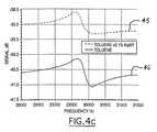
- the representative circuit shown in FIG. 4 badds a parallel resistor Rp in parallel to capacitor Cp to illustrate a circuit that measures conductivity as well as dielectric constant and viscosity, preferably by comparing the equivalent resistance found in a given liquid with a known resistance found via calibration.
- Rprepresents the conductivity of the liquid being tested. The resistance can be calibrated using a set of liquids having known conductivity and then used to measure the conductivity of a given liquid. For example, FIG.
- 4 cshows a sample trace comparing the resonator response in pure toluene and in KaBr toluene solution.
- a liquid having greater conductivitytends to shift the resonator response upward on the graph, similar to liquids having higher dielectric constants.
- a liquid having greater conductivitywill also cause the resonator response to level out somewhat in the frequency sweep, as can be seen in the upper trace 45 between 30 and 31.5 kHz.
- the difference between the upper trace 45 and the lower trace 46indicates that the equivalent resistance Rp caused by the additional KaBr in solution was about 8 mega-ohms.
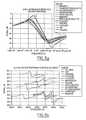
- FIGS. 5 a-b , 6 a-b , 7 a-b and 8 a-bare examples demonstrating the effectiveness of the invention. These figures show some differences between the frequency responses, for various liquid compositions, of the plate-type TSM resonator 10 and the tuning fork resonator 20 .
- FIGS. 5 a , 6 a , 7 a and 8 aare examples using the TSM resonator 10
- FIGS. 6 b , 6 b , 7 b and 8 bare examples using the tuning fork resonator 20 .
- the experimental conditions for generating the example tuning fork resonator traces in FIGS. 6 b , 6 b , 7 b , and 8 bare described below.
- the experimental conditions for generating the comparative TSM resonator traces in FIGS. 5 a , 6 a , 7 a and 8 aare generally similar to, if not the same as, the conditions for the tuning fork resonator except for, if needed, minor modifications to accommodate the TSM resonator's particular geometry. Therefore, for simplicity and clarity, the TSM resonator's particular experimental conditions will not be described separately.
- the tuning fork resonator response in airwas measured as a reference.
- the actual testing processeswere conducted in a temperature-controlled laboratory set at around 20 degrees Centicrade. Once the liquid was delivered to the well, the tuning fork was placed in the well and the system was left alone to allow the temperature to stabilize. Alternatively, the tuning fork can be built into a wall portion or a bottom portion of the well with equally accurate results. The tuning fork was then oscillated using the network analyzer. The resonator response was recorded during each measurement and stored in a computer memory. The measured response curve was fitted to a model curve using an equivalent circuit, which provided specific values for the equivalent circuit components described above with respect to FIGS. 4 a and 4 b and the traces in FIGS. 6 a through 8 b.
- the resonatorwas kept in the well and pure solvent was poured inside the well to dissolve any polymer residue or coating in the well and on the tuning fork.
- the well and tuning forkwere blown dry using dry air, and the tuning fork response in air was measured again and compared with the initial tuning fork measurement to ensure that the tuning fork was completely clean; a clean tuning fork would give the same response as the initial tuning fork response.
- the operating frequency of the tuning fork resonator 20varies according to the resonator's geometry; more particularly, the resonance frequency of the tuning fork 20 depends on the ratio between the tine cross-sectional area and the tine's length. Theoretically, it is possible to construct a tuning fork resonator 20 of any length for a given frequency by changing the tuning fork's cross-sectional area to keep the ratio between the length and the cross-section constant. In practice, however, tuning fork resonators 20 are manufactured from quartz wafers having a few selected standard thicknesses.
- the solutions used as examples in FIGS. 5 a and 5 bhave somewhat similar structures and weights.
- the TSM resonator responses for each solutionshown in FIG. 5 a , create very similar traces in the same general range. Because the traces associated with the TSM resonator 10 overlap each other to such a great extent, it is difficult to isolate and compare the differences between the responses associated with each solution.
- the increased sensitivity of the tuning fork resonator 20causes small differences in the chemical structure to translate into significant differences in the resonator response. Because the traces generated by the tuning fork resonator 20 are so distinct and spaced apart, they are much easier to analyze and compare.
- Using a tuning fork resonator 20 to measure properties of liquidsalso results in greater linearity in the relationship between the square root of the product of the liquid's viscosity density and the equivalent serial resistance Rs (FIGS. 6 a and 6 b ) as well as in the relationship between the dielectric constant and the equivalent parallel capacitance Cp (FIGS. 7 a and 7 b ) compared to TSM resonators 10 .
- the relationship between the liquid viscosity and serial resistance for a tuning fork resonator 20is much more linear than that for the TSM resonator, as shown in FIG. 6 a.
- FIGS. 8 a and 8 billustrate sample results from real-time monitoring of polymerization reactions by a TSM resonator and a tuning fork resonator, respectively.
- the graphsplot the equivalent resistance Rs of the resonators oscillating in 10 and 20 mg/ml polystyrene-toluene solutions versus the average molecular weight of polystyrene. As explained above, high molecular weight solutions often exhibit different physical characteristics, such as viscosity, at higher frequencies.
- the tuning fork resonator 20can be coated with a selected material to change how the resonator 20 is affected by a fluid composition (which, as explained earlier, includes both liquid and vapor compositions).
- a fluid compositionwhich, as explained earlier, includes both liquid and vapor compositions.
- one optionis a general coating for providing the tuning fork resonator 20 with additional properties such as corrosion resistance, chemical resistance, electrical resistance, and the like.
- Another option, as noted above,is using a “functionality”, which coats the tines with materials that are designed for a specific application, such as proteins to allow the tuning fork resonator 20 to be used as a pH meter or receptors that attract specific substances in the fluid composition to detect the presence of those substances.
- FIGS. 9 a and 9 bAn example of a tuning, fork resonator that has undergone a functionalization treatment is illustrated in FIGS. 9 a and 9 b .
- FIG. 9 arepresents a tuning fork tine 22 that has been treated by absorbing, coating, or otherwise surrounding the tine 22 with a functionality designed to change the tuning fork's resonance frequency after being exposed to a selected target chemical.
- the tuning fork tine 22is covered with receptor molecules 90 , represented in FIGS. 9 a and 9 b by Y-shaped members, designed to bond with specific target molecules.
- the resonance frequency and the damping of the tuning fork resonatordepends on the effective mass of the tine 22 and the amount of “drag” of the tine 22 within the fluid, any change in the tine's mass or the amount of drag will change the tuning fork's resonance response. More specifically, the resonance frequency of the tuning fork resonator is proportional to the square root of the inverse of the tuning fork's mass. An increase in the tuning fork's mass will therefore reduce the tuning fork's resonance frequency.
- This mass-frequency relationshipis used to detect the presence of a specific target chemical in a fluid composition in this example.
- the receptors 90 on the tuning fork tine 22will chemically bond with molecules of the target chemical 92 , as shown in FIG. 9 b .
- the resonance frequency of the tuning fork resonatorwill consequently decrease because of the increased mass and the additional drag created by the additional molecules 92 attached to the tuning fork tines 22 via the receptor molecules 90 .
- only the fluid compositions containing the target chemicalwill cause the tuning fork's resonance frequency to change.
- the tuning fork tines 22can be functionalized with a material that physically changes when exposed to molecules of a selected chemical such that the material changes the mechanical drag on the tuning fork tine 22 when it is exposed to the selected chemical.
- adding a hydrophobic or hydrophilic functionality to the tuning fork tine 22allows the tine 22 to attract or repel selected substances in the medium being analyzed, changing the mass or effective mass of the tuning fork and thereby changing its resonance frequency.
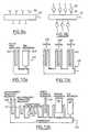
- multiple mechanical resonatorscan be attached together in a single sensor to measure a wider range of responses for a given fluid composition, as shown in FIGS. 10 a , 10 b and 10 c .
- the multiple resonator sensorcan be fabricated from a single quartz piece such that all of the resonators are attached together by a common base, as shown in the figures.
- the multi-resonator sensorcould also be attached to multiple frequency generating circuits, such as multiple network analyzers 28 , to measure properties of the fluid compositions over multiple frequency sweeps so that the generated data can be correlated to obtain additional information about the liquid compositions.
- FIGS. 10 a , 10 b and 10 cshow specific examples of possible multi-resonator configurations, but those of skill in the art would understand that sensors having any combination of resonators can be constructed without departing from the scope of the invention.
- FIG. 10 aillustrates one possible sensor 100 configuration containing both a tuning fork resonator 102 and a TSM resonator 104 .
- This type of sensor 100can be used to, for example, measure the mechanical and electrical properties of very thick liquids such as polymer resins and epoxies.
- This sensor 100can also be used to monitor a material as it polymerizes and hardens.
- the sensor 100can be placed in a liquid composition containing urethane rubber in its diluted state so that the tuning fork 102 is used initially to measure both the composition's density viscosity product and its dielectric constant. As the rubber changes to a gel and finally to a solid, the sensor 100 can switch to using the TSM resonator 104 to measure the rubber's mechanical properties, leaving the tuning fork resonator 102 to operate as a dielectric sensor only.
- a sensor 106 for observing a fluid composition over a wide frequency rangeis shown in FIG. 10 b .
- High polydispersity polymer solutionsare ideally measured over a wide frequency spectrum, but most resonators have optimum performance within a relatively limited frequency range.
- By combining different resonators having different resonance frequencies and different response characteristicsit is possible to obtain a more complete spectrum of resonator responses for analyzing the fluid's characteristics under many different conditions. For example, due to the wide spectrum of polydisperse solution relaxation times, it is generally predicted that high molecular weight compositions will react at lower frequencies than lighter molecular weight compositions.
- By changing the temperature, observing the frequency response of different resonators, and correlating the different resonator responsesit is possible to obtain a more accurate picture of a composition's relaxation spectrum than from a single resonator.
- the resonators in the multi-resonator sensor 106can also include a trident tuning fork resonator 112 , a length extension resonator 114 , a torsion resonator 116 , and a TSM resonator 118 , membrane oscillators, bimorphs, unimorphs, and various surface acoustic wave devices, as well as any combination thereof, or even a single resonator structure than can operate in multiple mechanical modes (e.g. compression mode, axial mode, torsion mode).
- a trident tuning fork resonator 112e.g., a length extension resonator 114 , a torsion resonator 116 , and a TSM resonator 118 , membrane oscillators, bimorphs, unimorphs, and various surface acoustic wave devices, as well as any combination thereof, or even a single resonator structure than can operate in multiple mechanical modes (e.g
- multiple resonators having the same structure but different coatings and/or functionalitiescan be incorporated into one sensor 120 , as shown in FIG. 10 c .
- a plurality of tuning fork resonators 122 , 124 , 126have the same structure but have different functionalities, each functionality designed to, for example, bond with a different target molecule.
- the high sensitivity of the tuning fork resonators 122 , 124 , 126makes them particularly suitable for “artificial noses” that can detect the presence of an environmentally-offending molecule, such as hydrogen sulfide or nitrous oxide, in industrial emissions.
- one tuning fork resonator 122can, for example, be functionalized with a material designed to bond with hydrogen sulfide while another resonator 124 can be functionalized with a material designed to bond with nitrous oxide.
- the presence of either one of these molecules in the fluid composition being testedwill cause the corresponding tuning fork resonator 122 , 124 to change its resonance frequency, as explained with respect to FIGS. 9 a and 9 b.
- the tuning fork resonators 122 , 124 , 126can also be functionalized with a polymer layer or other selective absorbing layer to detect the presence of specific molecules in a vapor. Because the tuning fork resonators 122 , 124 , 126 are highly sensitive to the dielectric constant of the surrounding fluid, the tuning fork resonators 122 , 124 , 126 can easily detect changes in the dielectric constant of the fluid and recognize a set of solvents with different dielectric constants in the fluid. This information, combined with other observable parameters, makes tuning fork resonators particularly adaptable for use in artificial noses.
- the method and system of the present inventionhas been described above in the combinatorial chemistry context, but it is not limited to such an application. Because the resonators in the method and system of the present invention have high sensitivities and quick response times, it can be also be used for in-line monitoring of fluid compositions flowing through conduits or pipelines.
- the inventioncan be used in a feedback system to monitor properties of liquids flowing through a gas or oil pipeline to monitor and control the concentration of additives in the gas or oil, or to detect the presence of impurities in water flowing through a water pipe. The additives or impurities will change the physical and electrical characteristics of the liquid flowing through the conduit.
- a functionalized tuning fork resonator 20can further detect the presence of a specific chemical in a fluid composition, whether it is a liquid or a vapor, and can be used to monitor the presence of, for example, a known chemical pollutant in a smokestack.
- the circuitry and system used to generate the visual traces from the resonator's responsecan be the same as described above or be any other equivalent resonator analysis system.
- TSM resonatorsany other mechanical resonators exhibiting similar characteristics can be used.
- Tridents, cantilevers, torsion bars, bimorphs, and/or membrane resonatorscan be substituted for the TSM resonator or tuning fork resonator without departing from the scope of the claimed invention.
Landscapes
- Physics & Mathematics (AREA)
- General Physics & Mathematics (AREA)
- Immunology (AREA)
- Pathology (AREA)
- Analytical Chemistry (AREA)
- Biochemistry (AREA)
- General Health & Medical Sciences (AREA)
- Life Sciences & Earth Sciences (AREA)
- Health & Medical Sciences (AREA)
- Chemical & Material Sciences (AREA)
- Acoustics & Sound (AREA)
- Engineering & Computer Science (AREA)
- Signal Processing (AREA)
- Investigating Or Analyzing Materials By The Use Of Electric Means (AREA)
- Degasification And Air Bubble Elimination (AREA)
- Investigating Or Analyzing Materials By The Use Of Ultrasonic Waves (AREA)
Abstract
Description
Claims (16)
Priority Applications (1)
| Application Number | Priority Date | Filing Date | Title |
|---|---|---|---|
| US09/801,165US6336353B2 (en) | 1997-10-08 | 2001-03-07 | Method and apparatus for characterizing materials by using a mechanical resonator |
Applications Claiming Priority (3)
| Application Number | Priority Date | Filing Date | Title |
|---|---|---|---|
| US08/946,921US6182499B1 (en) | 1996-10-09 | 1997-10-08 | Systems and methods for characterization of materials and combinatorial libraries with mechanical oscillators |
| US09/133,171US6393895B1 (en) | 1997-10-08 | 1998-08-12 | Method and apparatus for characterizing materials by using a mechanical resonator |
| US09/801,165US6336353B2 (en) | 1997-10-08 | 2001-03-07 | Method and apparatus for characterizing materials by using a mechanical resonator |
Related Parent Applications (1)
| Application Number | Title | Priority Date | Filing Date |
|---|---|---|---|
| US09/133,171DivisionUS6393895B1 (en) | 1997-10-08 | 1998-08-12 | Method and apparatus for characterizing materials by using a mechanical resonator |
Publications (2)
| Publication Number | Publication Date |
|---|---|
| US20010010174A1 US20010010174A1 (en) | 2001-08-02 |
| US6336353B2true US6336353B2 (en) | 2002-01-08 |
Family
ID=26831126
Family Applications (2)
| Application Number | Title | Priority Date | Filing Date |
|---|---|---|---|
| US09/133,171Expired - Fee RelatedUS6393895B1 (en) | 1997-10-08 | 1998-08-12 | Method and apparatus for characterizing materials by using a mechanical resonator |
| US09/801,165Expired - LifetimeUS6336353B2 (en) | 1997-10-08 | 2001-03-07 | Method and apparatus for characterizing materials by using a mechanical resonator |
Family Applications Before (1)
| Application Number | Title | Priority Date | Filing Date |
|---|---|---|---|
| US09/133,171Expired - Fee RelatedUS6393895B1 (en) | 1997-10-08 | 1998-08-12 | Method and apparatus for characterizing materials by using a mechanical resonator |
Country Status (7)
| Country | Link |
|---|---|
| US (2) | US6393895B1 (en) |
| EP (1) | EP0943091B2 (en) |
| AT (1) | ATE239227T1 (en) |
| AU (1) | AU9599898A (en) |
| DE (1) | DE69814035T3 (en) |
| ES (1) | ES2199467T3 (en) |
| WO (1) | WO1999018431A1 (en) |
Cited By (76)
| Publication number | Priority date | Publication date | Assignee | Title |
|---|---|---|---|---|
| US20020029621A1 (en)* | 2000-05-26 | 2002-03-14 | Symyx Technologies, Inc. | Instrument for high throughput measurement of material physical properties and method of using same |
| US20020131228A1 (en)* | 2001-03-13 | 2002-09-19 | Potter Michael D. | Micro-electro-mechanical switch and a method of using and making thereof |
| US6484567B1 (en) | 2000-08-03 | 2002-11-26 | Symyx Technologies, Inc. | Rheometer for rapidly measuring small quantity samples |
| US20020178787A1 (en)* | 1997-10-08 | 2002-12-05 | Symyx Technologies, Inc. | Method and apparatus for characterizing materials by using a mechanical resonator |
| US20020182091A1 (en)* | 2001-05-31 | 2002-12-05 | Potter Michael D. | Micro fluidic valves, agitators, and pumps and methods thereof |
| WO2002099414A1 (en)* | 2001-06-06 | 2002-12-12 | Symyx Technologies, Inc. | Flow detectors having mechanical oscillators, and use thereof in flow characterization systems |
| WO2002093126A3 (en)* | 2001-05-15 | 2003-01-09 | Baker Hughes Inc | Method and apparatus for downhole fluid characterization using flxural mechanical resonators |
| US20030041676A1 (en)* | 2001-08-24 | 2003-03-06 | Symyx Technologies, Inc. | High throuhput mechanical property testing of materials libraries using a piezoelectric |
| US20030041672A1 (en)* | 2001-08-24 | 2003-03-06 | Symyx Technologies , Inc. | High throughput mechanical property and bulge testing of materials libraries |
| US20030055587A1 (en)* | 2001-09-17 | 2003-03-20 | Symyx Technologies, Inc. | Rapid throughput surface topographical analysis |
| US20030141613A1 (en)* | 2002-01-31 | 2003-07-31 | Symyx Technologies, Inc. | High throughput preparation and analysis of plastically shaped material samples |
| US20030154031A1 (en)* | 2002-02-14 | 2003-08-14 | General Electric Company | Method and apparatus for the rapid evaluation of a plurality of materials or samples |
| US20030203500A1 (en)* | 2002-04-26 | 2003-10-30 | Symyx Technologies, Inc. | High throughput testing of fluid samples using an electric field |
| US20030218467A1 (en)* | 2002-05-24 | 2003-11-27 | Symyx Technologies, Inc. | High throughput microbalance and methods of using same |
| US20040023236A1 (en)* | 2001-10-26 | 2004-02-05 | Potter Michael D. | Chemical and biological hazard sensor system and methods thereof |
| US20040077091A1 (en)* | 2002-10-18 | 2004-04-22 | Symyx Technologies, Inc. | High throughput permeability testing of materials libraries |
| WO2004036191A1 (en)* | 2002-10-18 | 2004-04-29 | Symyx Technologies, Inc. | Machine fluid sensor and method |
| US6736017B2 (en) | 2001-08-24 | 2004-05-18 | Symyx Technologies, Inc. | High throughput mechanical rapid serial property testing of materials libraries |
| US20040107055A1 (en)* | 2002-10-18 | 2004-06-03 | Symyx Technologies, Inc. | Application specific integrated circuitry for controlling analysis of a fluid |
| US20040123650A1 (en)* | 2002-09-17 | 2004-07-01 | Symyx Technologies, Inc. | High throughput rheological testing of materials |
| US20040145271A1 (en)* | 2001-10-26 | 2004-07-29 | Potter Michael D | Electrostatic based power source and methods thereof |
| US20040155555A1 (en)* | 2001-10-26 | 2004-08-12 | Potter Michael D. | Electrostatic based power source and methods thereof |
| WO2004086002A1 (en) | 2003-03-21 | 2004-10-07 | Symyx Technologies, Inc. | Resonator sensor assembly |
| US20040236512A1 (en)* | 2001-05-15 | 2004-11-25 | Baker Hughes Inc. | Method and apparatus for chemometric estimations of fluid density, viscosity, dielectric constant, and resistivity from mechanical resonator data |
| US20040244487A1 (en)* | 2003-03-21 | 2004-12-09 | Symyx Technologies, Inc. | Mechanical resonator |
| US20050009197A1 (en)* | 2003-02-11 | 2005-01-13 | Adams Jesse D. | Chemical sensor with oscillating cantilevered probe and mechanical stop |
| US20050016276A1 (en)* | 2003-06-06 | 2005-01-27 | Palo Alto Sensor Technology Innovation | Frequency encoding of resonant mass sensors |
| US6857309B2 (en) | 2001-08-24 | 2005-02-22 | Symyx Technologies, Inc. | High throughput mechanical rapid serial property testing of materials libraries |
| US20050044955A1 (en)* | 2003-08-29 | 2005-03-03 | Potter Michael D. | Methods for distributed electrode injection and systems thereof |
| US20050092072A1 (en)* | 2003-10-31 | 2005-05-05 | Wollenberg Robert H. | High throughput screening methods for lubricating oil compositions |
| US20050095716A1 (en)* | 2003-10-31 | 2005-05-05 | Wollenberg Robert H. | High throughput screening methods for lubricating oil compositions |
| US20050095714A1 (en)* | 2003-10-31 | 2005-05-05 | Wollenberg Robert H. | High throughput preparation of lubricating oil compositions for combinatorial libraries |
| US20050096895A1 (en)* | 2003-10-31 | 2005-05-05 | Wollenberg Robert H. | Method and system of product development process for chemical compositions using high volume modeling |
| US20050095717A1 (en)* | 2003-10-31 | 2005-05-05 | Wollenberg Robert H. | High throughput screening methods for lubricating oil compositions |
| US20050109098A1 (en)* | 2003-11-21 | 2005-05-26 | Baker Hughes Incorporated | Method and apparatus for downhole fluid analysis using molecularly imprinted polymers |
| US20050145019A1 (en)* | 2002-10-18 | 2005-07-07 | Symyx Technologies, Inc. | Environmental control system fluid sensing system and method |
| US20050178190A1 (en)* | 2004-02-13 | 2005-08-18 | Wollenberg Robert H. | High throughput screening methods for lubricating oil compositions |
| US20050181512A1 (en)* | 2004-02-13 | 2005-08-18 | Wollenberg Robert H. | High throughput screening methods for lubricating oil compositions |
| US20050199047A1 (en)* | 2003-03-11 | 2005-09-15 | Adams Jesse D. | Liquid cell and passivated probe for atomic force microscopy and chemical sensing |
| US20050209796A1 (en)* | 2003-03-21 | 2005-09-22 | Symyx Technologies, Inc. | Integrated circuitry for controlling analysis of a fluid |
| US20050205966A1 (en)* | 2004-02-19 | 2005-09-22 | Potter Michael D | High Temperature embedded charge devices and methods thereof |
| US20050211622A1 (en)* | 2001-08-10 | 2005-09-29 | Symyx Technologies, Inc. | Apparatuses and methods for creating and testing pre-formulations and systems for same |
| US20050247119A1 (en)* | 2001-05-15 | 2005-11-10 | Baker Hughes Incorporated | Method and apparatus for downhole fluid characterization using flexural mechanical resonators |
| US20060032301A1 (en)* | 2004-08-12 | 2006-02-16 | Baker Hughes, Incorporated | Method and apparatus for downhole detection of CO2 and H2S using resonators coated with CO2 and H2S sorbents |
| US20060137873A1 (en)* | 2004-12-23 | 2006-06-29 | Derek Caudwell | Apparatus and method for formation evaluation |
| US20060257286A1 (en)* | 2003-10-17 | 2006-11-16 | Adams Jesse D | Self-sensing array of microcantilevers for chemical detection |
| US20060277979A1 (en)* | 2005-06-08 | 2006-12-14 | Eric Fitch | Methods and apparatus for determining properties of a fluid |
| US20070003450A1 (en)* | 2005-07-01 | 2007-01-04 | Ian Burdett | Systems and methods for monitoring solids using mechanical resonator |
| US20070017276A1 (en)* | 2005-07-20 | 2007-01-25 | Trutna William R Jr | Resonant structure humidity sensor |
| US20070017291A1 (en)* | 2005-04-01 | 2007-01-25 | Symyx Technologies, Inc. | Monitoring and controlling unit operations |
| US20070052970A1 (en)* | 2003-03-21 | 2007-03-08 | Symyx Technologies, Inc. | Resonator sensor assembly |
| US20070060721A1 (en)* | 2005-09-14 | 2007-03-15 | Muhle Michael E | Method for operating a gas-phase reactor at or near maximum production rates while controlling polymer stickiness |
| US7194902B1 (en) | 2004-12-23 | 2007-03-27 | Schlumberger Technology Corporation | Apparatus and method for formation evaluation |
| US20070074731A1 (en)* | 2005-10-05 | 2007-04-05 | Nth Tech Corporation | Bio-implantable energy harvester systems and methods thereof |
| US7217582B2 (en) | 2003-08-29 | 2007-05-15 | Rochester Institute Of Technology | Method for non-damaging charge injection and a system thereof |
| US7272525B2 (en) | 2004-04-21 | 2007-09-18 | Visyx Technologies, Inc. | Portable fluid sensing device and method |
| US20080085212A1 (en)* | 2004-10-01 | 2008-04-10 | Adams Jesse D | Cantilevered Probe Detector With Piezoelectric Element |
| US20080215245A1 (en)* | 2007-01-19 | 2008-09-04 | Baker Hughes Incorporated | System and method for determining producibility of a formation using flexural mechanical resonator measurements |
| US7462490B2 (en) | 2003-10-31 | 2008-12-09 | Chevron Oronite Company Llc | Combinatorial lubricating oil composition libraries |
| US20090100925A1 (en)* | 2006-10-27 | 2009-04-23 | Baker Hughes Incorporated | System and method for coating flexural mechanical resonators |
| DE102007053221A1 (en)* | 2007-11-06 | 2009-05-07 | Endress + Hauser Gmbh + Co. Kg | Method for determining and / or monitoring the growth of a biological substance in a medium |
| US20090288479A1 (en)* | 2003-11-17 | 2009-11-26 | Woody Shane C | Standing wave fluidic and biological tools |
| US20090320568A1 (en)* | 2007-01-25 | 2009-12-31 | Guido Desie | Method and apparatus for measuring viscosity and surface tension |
| US20100015649A1 (en)* | 2006-12-28 | 2010-01-21 | Highland Biosciences Limited | Biosensor |
| US20100222235A1 (en)* | 2004-02-13 | 2010-09-02 | Chevron Oronite Company Llc | High throughput screening methods for fuel compositions |
| US20110129929A1 (en)* | 2007-08-24 | 2011-06-02 | Highland Biosciences Limited | Apparatus and method for determining the results of assays |
| US7985592B2 (en) | 2004-02-13 | 2011-07-26 | Chevron Oronite Company Llc | High throughput screening methods for lubricating oil compositions |
| US8409875B2 (en) | 2010-10-20 | 2013-04-02 | Rapid Diagnostek, Inc. | Measurement of binding kinetics with a resonating sensor |
| US8878548B2 (en) | 2010-06-11 | 2014-11-04 | Baker Hughes Incorporated | Method for treating and sealing piezoelectric tuning forks |
| US9038443B1 (en)* | 2011-12-14 | 2015-05-26 | Maria Esther Pace | Microfabricated resonant fluid density and viscosity sensor |
| US9752911B2 (en) | 2014-12-29 | 2017-09-05 | Concentric Meter Corporation | Fluid parameter sensor and meter |
| US20180209941A1 (en)* | 2014-04-04 | 2018-07-26 | Commissariat A L'energie Atomique Et Aux Energies Alternatives | Device for detecting and/or measuring out at least one chemical compound, and chamber for forming such a device |
| US10107784B2 (en) | 2014-12-29 | 2018-10-23 | Concentric Meter Corporation | Electromagnetic transducer |
| US10126266B2 (en) | 2014-12-29 | 2018-11-13 | Concentric Meter Corporation | Fluid parameter sensor and meter |
| US20220011209A1 (en)* | 2018-12-12 | 2022-01-13 | Micro Motion, Inc. | Planar vibratory densitometer, densitometer member, and related method |
| US20220299350A1 (en)* | 2019-08-20 | 2022-09-22 | Micro Motion, Inc. | Stabilized mode splitting fin sensor |
Families Citing this family (31)
| Publication number | Priority date | Publication date | Assignee | Title |
|---|---|---|---|---|
| US6468410B1 (en) | 1999-06-14 | 2002-10-22 | Eveready Battery Company, Inc. | Method for synthesis and characterization of electrode materials |
| US7033840B1 (en) | 1999-11-09 | 2006-04-25 | Sri International | Reaction calorimeter and differential scanning calorimeter for the high-throughput synthesis, screening and characterization of combinatorial libraries |
| AU1476601A (en)* | 1999-11-09 | 2001-06-06 | Sri International | Array for the high-throughput synthesis, screening and characterization of combinatorial libraries, and methods for making the array |
| US6881585B1 (en) | 2000-03-06 | 2005-04-19 | General Electric Company | Method and apparatus for rapid screening of volatiles |
| EP1311822A4 (en)* | 2000-07-10 | 2008-12-03 | Nanoalert Israel Ltd | Method and apparatus for determining the composition of fluids |
| US20020055111A1 (en)* | 2000-08-25 | 2002-05-09 | Shiping Chen | Three-dimensional probe carriers |
| US6837115B2 (en) | 2001-08-24 | 2005-01-04 | Symyx Technologies, Inc. | High throughput mechanical rapid serial property testing of materials libraries |
| US6769292B2 (en) | 2001-08-24 | 2004-08-03 | Symyx Technologies, Inc | High throughput rheological testing of materials |
| US6860148B2 (en) | 2001-08-24 | 2005-03-01 | Symyx Technologies, Inc. | High throughput fabric handle screening |
| EP1646864B1 (en) | 2003-07-18 | 2018-11-07 | Rosemount Inc. | Process diagnostics |
| US7350403B2 (en)* | 2003-07-21 | 2008-04-01 | Aria Analyties, Inc. | Method and apparatus for determination of food quality and authenticity |
| US7350402B2 (en)* | 2003-07-21 | 2008-04-01 | Aria Analytics, Inc. | Method and apparatus for determination of medical diagnostics utilizing biological fluids |
| US20050054116A1 (en)* | 2003-09-05 | 2005-03-10 | Potyrailo Radislav A. | Method of manufacturing and evaluating sensor coatings and the sensors derived therefrom |
| JP2005302794A (en)* | 2004-04-07 | 2005-10-27 | Hitachi Industrial Equipment Systems Co Ltd | Transformer monitoring system |
| US8215170B2 (en)* | 2004-05-10 | 2012-07-10 | Arizona Board Of Regents | Chemical and biological sensing using tuning forks |
| NZ554295A (en)* | 2004-09-17 | 2010-04-30 | Bp Oil Int | Portable apparatus for analysis of a refinery feedstock or a product of a refinery process |
| DE102004049580A1 (en)* | 2004-10-12 | 2006-04-13 | Robert Bosch Gmbh | Method for detecting state parameters of a liquid |
| KR100639064B1 (en) | 2005-05-19 | 2006-10-30 | 한국과학기술원 | Material detection device and detection method using rigidity of detection material |
| US7523640B2 (en)* | 2005-08-01 | 2009-04-28 | Baker Hughes Incorporated | Acoustic fluid analyzer |
| US7614302B2 (en)* | 2005-08-01 | 2009-11-10 | Baker Hughes Incorporated | Acoustic fluid analysis method |
| DE102006000842A1 (en)* | 2006-01-05 | 2007-07-12 | Hella Kgaa Hueck & Co. | Method and device for detecting the condition of an air filter of an air conditioner |
| DE102007035770B4 (en)* | 2007-07-27 | 2011-04-14 | Continental Automotive Gmbh | Device for determining the viscosity and / or density of a liquid |
| US20120270330A1 (en)* | 2009-09-14 | 2012-10-25 | Arizona Board Of Regents For And On Behalf Of Arizona State University | Hybrid Separation and Detection Device for Chemical Detection and Analysis |
| CN102576597A (en)* | 2009-10-01 | 2012-07-11 | Abb技术有限公司 | Thermal modelling of a transformer |
| CA2691554A1 (en)* | 2010-02-01 | 2011-08-01 | Michael Krautter | Crystal growing device |
| FR2969762B1 (en) | 2010-12-22 | 2013-02-08 | Commissariat Energie Atomique | ATOMIC FORCE MICROSCOPE PROBE, PROCESS FOR PREPARING THE SAME AND USES THEREOF |
| US9062532B2 (en)* | 2011-03-10 | 2015-06-23 | Baker Hughes Incorporated | Electromagnetic viscosity sensor |
| US20130063149A1 (en)* | 2011-07-14 | 2013-03-14 | Baker Hughes Incorporated | Reducing fluid capacitance and conductance effects on piezoelectric resonator measurements |
| WO2016138320A1 (en)* | 2015-02-27 | 2016-09-01 | California Institute Of Technology | Temperature sensor using piezoelectric resonator and methods of measuring temperature |
| US11641168B2 (en)* | 2017-07-17 | 2023-05-02 | Georgia Tech Research Corporation | Parametric resonator for electrical transduction |
| US11768178B2 (en) | 2020-02-28 | 2023-09-26 | Baker Hughes Oilfield Operations Llc | Embedded electrode tuning fork |
Citations (30)
| Publication number | Priority date | Publication date | Assignee | Title |
|---|---|---|---|---|
| US3622968A (en) | 1969-05-15 | 1971-11-23 | Amoco Prod Co | Elastic-wave holography using reflections |
| US3902365A (en) | 1970-04-24 | 1975-09-02 | Rotron Inc | Mass flow monitoring system and method |
| US4349881A (en) | 1980-07-14 | 1982-09-14 | International Telephone And Telegraph Corporation | Vibration instruments |
| US4391338A (en) | 1980-04-04 | 1983-07-05 | Harvey Patashnick | Microbalance and method for measuring the mass of matter suspended within a fluid medium |
| EP0102490A1 (en) | 1982-08-04 | 1984-03-14 | Bopp & Reuther Aktiengesellschaft | Densitometer for gases |
| US4526480A (en) | 1983-06-21 | 1985-07-02 | Quartztronics, Inc. | Fluid density temperature measurement apparatus and method |
| US4596697A (en) | 1984-09-04 | 1986-06-24 | The United States Of America As Represented By The Secretary Of The Army | Chemical sensor matrix |
| US4721874A (en) | 1986-10-06 | 1988-01-26 | Emmert Sans W | Apparatus and method for determining the viscosity of a fluid sample |
| US4729237A (en) | 1985-12-12 | 1988-03-08 | Chichibu Cement Kabushiki Kaisha | Tuning fork vibration-type viscosity measuring apparatus |
| US4734609A (en) | 1986-07-25 | 1988-03-29 | Calogic Corporation | Gas density transducer |
| US4741200A (en) | 1986-07-11 | 1988-05-03 | Ford Motor Company | Method and apparatus for measuring viscosity in a liquid utilizing a piezoelectric sensor |
| US4760351A (en) | 1986-08-22 | 1988-07-26 | Northern Illinois University | Multiple oscillator device having plural quartz resonators in a common quartz substrate |
| US4767719A (en) | 1986-05-20 | 1988-08-30 | Amersham International Plc | Assay apparatus having piezoelectric slab generating effective diffraction grating in applied analyte-specific film |
| EP0282251A2 (en) | 1987-03-11 | 1988-09-14 | Solartron Group Limited | Fluid transducer |
| US5179028A (en) | 1990-04-20 | 1993-01-12 | Hughes Aircraft Company | Antibody coated crystal chemical sensor |
| US5201215A (en)* | 1991-10-17 | 1993-04-13 | The United States Of America As Represented By The United States Department Of Energy | Method for simultaneous measurement of mass loading and fluid property changes using a quartz crystal microbalance |
| US5283037A (en) | 1988-09-29 | 1994-02-01 | Hewlett-Packard Company | Chemical sensor utilizing a surface transverse wave device |
| US5296374A (en) | 1989-10-20 | 1994-03-22 | University Of Strathclyde | Apparatus for assessing a particular property in a medium |
| US5306644A (en) | 1988-09-29 | 1994-04-26 | Hewlett-Packard Company | Mass sensor method for measuring analytes in a sample |
| US5455475A (en)* | 1993-11-01 | 1995-10-03 | Marquette University | Piezoelectric resonant sensor using the acoustoelectric effect |
| EP0676638A2 (en) | 1994-04-11 | 1995-10-11 | Tektronix, Inc. | Time-interleaved method for efficient operation of an acoustic wave sensor array |
| US5571401A (en) | 1995-03-27 | 1996-11-05 | California Institute Of Technology | Sensor arrays for detecting analytes in fluids |
| US5705399A (en) | 1994-05-20 | 1998-01-06 | The Cooper Union For Advancement Of Science And Art | Sensor and method for detecting predetermined chemical species in solution |
| US5734098A (en)* | 1996-03-25 | 1998-03-31 | Nalco/Exxon Energy Chemicals, L.P. | Method to monitor and control chemical treatment of petroleum, petrochemical and processes with on-line quartz crystal microbalance sensors |
| US5744902A (en) | 1995-05-16 | 1998-04-28 | The United States Of America As Represented By The Secretary Of The Army | Chemical and biological sensor based on microresonators |
| US5770038A (en) | 1994-06-29 | 1998-06-23 | Sanyo Electric Co., Ltd. | Method for detecting chemical substances |
| US5776359A (en)* | 1994-10-18 | 1998-07-07 | Symyx Technologies | Giant magnetoresistive cobalt oxide compounds |
| US5798452A (en) | 1993-08-18 | 1998-08-25 | Sandia Corporation | Textured-surface quartz resonator fluid density and viscosity monitor |
| US5852229A (en)* | 1996-05-29 | 1998-12-22 | Kimberly-Clark Worldwide, Inc. | Piezoelectric resonator chemical sensing device |
| US6182499B1 (en)* | 1996-10-09 | 2001-02-06 | Symyx Technologies | Systems and methods for characterization of materials and combinatorial libraries with mechanical oscillators |
Family Cites Families (19)
| Publication number | Priority date | Publication date | Assignee | Title |
|---|---|---|---|---|
| US3718032A (en) | 1970-09-18 | 1973-02-27 | Hoffmann La Roche | Ultrasonic visualization |
| US3778757A (en) | 1972-09-01 | 1973-12-11 | Gen Electric | Method and apparatus for visual imaging ultrasonic echo signals utilizing multiple transmitters for reduced specular reflection effects |
| US4370662A (en) | 1980-12-02 | 1983-01-25 | Ricoh Company, Ltd. | Ink jet array ultrasonic simulation |
| US4342936A (en) | 1980-12-19 | 1982-08-03 | Eastman Kodak Company | High deflection bandwidth product polymeric piezoelectric flexure mode device and method of making same |
| DE3301967A1 (en) | 1983-01-21 | 1984-07-26 | Siemens AG, 1000 Berlin und 8000 München | ULTRASONIC IMAGING SYSTEM |
| US4779451A (en) | 1986-02-17 | 1988-10-25 | Hitachi, Ltd. | System for measuring foreign materials in liquid |
| US4910523A (en) | 1987-11-06 | 1990-03-20 | Millitech Corporation | Micrometer wave imaging device |
| EP0262637B1 (en) | 1986-09-29 | 1995-03-22 | Mitsubishi Chemical Corporation | Piezoelectric actuator |
| US5206806A (en) | 1989-01-10 | 1993-04-27 | Gerardi Joseph J | Smart skin ice detection and de-icing system |
| US5224174A (en) | 1990-11-07 | 1993-06-29 | Niagara Technology Incorporated | Surface feature mapping using high resolution c-scan ultrasonography |
| US5375470A (en) | 1990-12-20 | 1994-12-27 | Fujitsu Limited | Acoustic imaging system |
| US5253530A (en) | 1991-08-12 | 1993-10-19 | Letcher Iii John H | Method and apparatus for reflective ultrasonic imaging |
| US5846708A (en) | 1991-11-19 | 1998-12-08 | Massachusetts Institiute Of Technology | Optical and electrical methods and apparatus for molecule detection |
| US5469369A (en) | 1992-11-02 | 1995-11-21 | The United States Of America As Represented By The Secretary Of The Navy | Smart sensor system and method using a surface acoustic wave vapor sensor array and pattern recognition for selective trace organic vapor detection |
| US5524636A (en) | 1992-12-21 | 1996-06-11 | Artann Corporation Dba Artann Laboratories | Method and apparatus for elasticity imaging |
| US5357964A (en) | 1993-02-08 | 1994-10-25 | Spivey Brett A | Doppler imaging device |
| US5454045A (en) | 1994-04-15 | 1995-09-26 | Battelle Memorial Institute | Apparatus and method for identification and recognition of an item with ultrasonic patterns from item subsurface micro-features |
| US6044694A (en) | 1996-08-28 | 2000-04-04 | Videojet Systems International, Inc. | Resonator sensors employing piezoelectric benders for fluid property sensing |
| US5899351A (en) | 1996-09-09 | 1999-05-04 | The Popstraw Company, Llc. | Device for containing and delivering a payload from a container |
- 1998
- 1998-08-12USUS09/133,171patent/US6393895B1/ennot_activeExpired - Fee Related
- 1998-10-02AUAU95998/98Apatent/AU9599898A/ennot_activeAbandoned
- 1998-10-02ESES98949736Tpatent/ES2199467T3/ennot_activeExpired - Lifetime
- 1998-10-02EPEP98949736Apatent/EP0943091B2/ennot_activeExpired - Lifetime
- 1998-10-02WOPCT/US1998/020764patent/WO1999018431A1/enactiveIP Right Grant
- 1998-10-02ATAT98949736Tpatent/ATE239227T1/ennot_activeIP Right Cessation
- 1998-10-02DEDE69814035Tpatent/DE69814035T3/ennot_activeExpired - Lifetime
- 2001
- 2001-03-07USUS09/801,165patent/US6336353B2/ennot_activeExpired - Lifetime
Patent Citations (34)
| Publication number | Priority date | Publication date | Assignee | Title |
|---|---|---|---|---|
| US3622968A (en) | 1969-05-15 | 1971-11-23 | Amoco Prod Co | Elastic-wave holography using reflections |
| US3902365A (en) | 1970-04-24 | 1975-09-02 | Rotron Inc | Mass flow monitoring system and method |
| US4391338A (en) | 1980-04-04 | 1983-07-05 | Harvey Patashnick | Microbalance and method for measuring the mass of matter suspended within a fluid medium |
| US4349881A (en) | 1980-07-14 | 1982-09-14 | International Telephone And Telegraph Corporation | Vibration instruments |
| EP0102490A1 (en) | 1982-08-04 | 1984-03-14 | Bopp & Reuther Aktiengesellschaft | Densitometer for gases |
| US4526480A (en) | 1983-06-21 | 1985-07-02 | Quartztronics, Inc. | Fluid density temperature measurement apparatus and method |
| US4596697A (en) | 1984-09-04 | 1986-06-24 | The United States Of America As Represented By The Secretary Of The Army | Chemical sensor matrix |
| US4729237A (en) | 1985-12-12 | 1988-03-08 | Chichibu Cement Kabushiki Kaisha | Tuning fork vibration-type viscosity measuring apparatus |
| US4767719A (en) | 1986-05-20 | 1988-08-30 | Amersham International Plc | Assay apparatus having piezoelectric slab generating effective diffraction grating in applied analyte-specific film |
| US4741200A (en) | 1986-07-11 | 1988-05-03 | Ford Motor Company | Method and apparatus for measuring viscosity in a liquid utilizing a piezoelectric sensor |
| US4734609A (en) | 1986-07-25 | 1988-03-29 | Calogic Corporation | Gas density transducer |
| US4760351A (en) | 1986-08-22 | 1988-07-26 | Northern Illinois University | Multiple oscillator device having plural quartz resonators in a common quartz substrate |
| US4721874A (en) | 1986-10-06 | 1988-01-26 | Emmert Sans W | Apparatus and method for determining the viscosity of a fluid sample |
| EP0282251A2 (en) | 1987-03-11 | 1988-09-14 | Solartron Group Limited | Fluid transducer |
| US4922745A (en) | 1987-03-11 | 1990-05-08 | Rudkin Mark J | Fluid transducer |
| US5306644A (en) | 1988-09-29 | 1994-04-26 | Hewlett-Packard Company | Mass sensor method for measuring analytes in a sample |
| US5283037A (en) | 1988-09-29 | 1994-02-01 | Hewlett-Packard Company | Chemical sensor utilizing a surface transverse wave device |
| US5296374A (en) | 1989-10-20 | 1994-03-22 | University Of Strathclyde | Apparatus for assessing a particular property in a medium |
| US5179028A (en) | 1990-04-20 | 1993-01-12 | Hughes Aircraft Company | Antibody coated crystal chemical sensor |
| US5201215A (en)* | 1991-10-17 | 1993-04-13 | The United States Of America As Represented By The United States Department Of Energy | Method for simultaneous measurement of mass loading and fluid property changes using a quartz crystal microbalance |
| US5798452A (en) | 1993-08-18 | 1998-08-25 | Sandia Corporation | Textured-surface quartz resonator fluid density and viscosity monitor |
| US5455475A (en)* | 1993-11-01 | 1995-10-03 | Marquette University | Piezoelectric resonant sensor using the acoustoelectric effect |
| EP0676638A2 (en) | 1994-04-11 | 1995-10-11 | Tektronix, Inc. | Time-interleaved method for efficient operation of an acoustic wave sensor array |
| US5488866A (en)* | 1994-04-11 | 1996-02-06 | Tektronix, Inc. | Time-interleaved method for efficient operation of an acoustic wave sensor array |
| US5705399A (en) | 1994-05-20 | 1998-01-06 | The Cooper Union For Advancement Of Science And Art | Sensor and method for detecting predetermined chemical species in solution |
| US5770038A (en) | 1994-06-29 | 1998-06-23 | Sanyo Electric Co., Ltd. | Method for detecting chemical substances |
| US5985356A (en)* | 1994-10-18 | 1999-11-16 | The Regents Of The University Of California | Combinatorial synthesis of novel materials |
| US5776359A (en)* | 1994-10-18 | 1998-07-07 | Symyx Technologies | Giant magnetoresistive cobalt oxide compounds |
| US5571401A (en) | 1995-03-27 | 1996-11-05 | California Institute Of Technology | Sensor arrays for detecting analytes in fluids |
| US5698089A (en) | 1995-03-27 | 1997-12-16 | California Institute Of Technology | Sensor arrays for detecting analytes in fluids |
| US5744902A (en) | 1995-05-16 | 1998-04-28 | The United States Of America As Represented By The Secretary Of The Army | Chemical and biological sensor based on microresonators |
| US5734098A (en)* | 1996-03-25 | 1998-03-31 | Nalco/Exxon Energy Chemicals, L.P. | Method to monitor and control chemical treatment of petroleum, petrochemical and processes with on-line quartz crystal microbalance sensors |
| US5852229A (en)* | 1996-05-29 | 1998-12-22 | Kimberly-Clark Worldwide, Inc. | Piezoelectric resonator chemical sensing device |
| US6182499B1 (en)* | 1996-10-09 | 2001-02-06 | Symyx Technologies | Systems and methods for characterization of materials and combinatorial libraries with mechanical oscillators |
Non-Patent Citations (9)
| Title |
|---|
| Fisch, M. R., et al., "Improved Acoustic Viscosimeter Technique", J. Acoust. Soc. Am., Sep. 1976, pp. 623-625, v. 60, No. 3. |
| Hiavay, J. and G. G. Guilbault, "Applications of the Piezoelectric Crystal Detector in Analytical Chemistry", Analytical Chemistry, Nov. 1977, pp. 1890-1898, v. 49, No. 13. |
| Kanazawa, K. Keiji and Joseph G. Gordon II, "The Oscillation Frequency of a Quartz Resonator in Contact with a Liquid", Analytica Chimica Acta, 1985, pp. 99-105, Elsevier Science Publishers B.V., Amsterdam. |
| Kipling, Arlin L and Michael Thompson, "Network Analysis Method Applied to Liquid-Phase Acoustic Wave Sensors", Anal. Chem., 1990, pp. 1514-1519, 62. |
| Michels, A. et al., "1 MHz Quartz Length Extension Resonator as a Probe for Scanning Near-Field Acoustic Microscopy", Thin Solid Films, 1995, pp. 172-175, 264. |
| Muramatsu, H. et al., "A Quartz Crystal Viscosity Sensor for Monitoring Coagulation Reaction and Its Application to a Multichannel Coagulation Detector", Biosensors & Bioelectronics, 1991, pp. 353-358, 6, Elsevier Science Publishers Ltd. England. |
| Muramatsu, Hiroshi et al., "Computation of Equivalent Circuit Parameters of Quartz Crystals in Contact with Liquids and Study of Liquid Properties", Anal. Chem., 1988, pp. 2142-2146, 60. |
| Nomura, T. and M. Iijima, "Electrolytic Determination of Nanomolar Concentrations of Silver in Solution with a Piezoelectric Quartz Crystal", Analytica Chimica Acta, 1981, pp. 97-102, 131, Elsevier Scientific Publishing Company. |
| PCT International Search Report, dated Apr. 27, 1998. |
Cited By (174)
| Publication number | Priority date | Publication date | Assignee | Title |
|---|---|---|---|---|
| US20040074303A1 (en)* | 1997-10-08 | 2004-04-22 | Symyx Technologies, Inc | Method and apparatus for characterizing materials by using a mechanical resonator |
| US6957565B2 (en) | 1997-10-08 | 2005-10-25 | Symyx Technologies, Inc. | Method and apparatus for characterizing materials by using a mechanical resonator |
| US20040074302A1 (en)* | 1997-10-08 | 2004-04-22 | Symyx Technologies, Inc. | Method and apparatus for characterizing materials by using a mechanical resonator |
| US20020178787A1 (en)* | 1997-10-08 | 2002-12-05 | Symyx Technologies, Inc. | Method and apparatus for characterizing materials by using a mechanical resonator |
| US7334452B2 (en)* | 1997-10-08 | 2008-02-26 | Visyx Technologies, Inc. | Method for characterizing materials by using a mechanical resonator |
| US6904786B2 (en) | 1997-10-08 | 2005-06-14 | Symyx Technologies, Inc. | Method and apparatus for characterizing materials by using a mechanical resonator |
| US7073370B2 (en) | 1997-10-08 | 2006-07-11 | Symyx Technologies | Method and apparatus for characterizing materials by using a mechanical resonator |
| US6936471B2 (en) | 2000-05-26 | 2005-08-30 | Symyx Technologies, Inc. | Instrument for high throughput measurement of material physical properties and method of using same |
| US20020029621A1 (en)* | 2000-05-26 | 2002-03-14 | Symyx Technologies, Inc. | Instrument for high throughput measurement of material physical properties and method of using same |
| US6679130B2 (en) | 2000-05-26 | 2004-01-20 | Symyx Technologies, Inc. | Instrument for high throughput measurement of material physical properties of a plurality of samples |
| US7047794B2 (en) | 2000-08-03 | 2006-05-23 | Symyx Technologies, Inc. | Tether plate sensor for measuring physical properties of fluid samples |
| US20040093932A1 (en)* | 2000-08-03 | 2004-05-20 | Symyx Technologies, Inc. | Rheometer for rapidly measuring small quantity samples |
| US20050166667A1 (en)* | 2000-08-03 | 2005-08-04 | Symyx Technologies, Inc. | Rheometer for rapidly measuring small quantity samples |
| US6484567B1 (en) | 2000-08-03 | 2002-11-26 | Symyx Technologies, Inc. | Rheometer for rapidly measuring small quantity samples |
| US6644101B2 (en) | 2000-08-03 | 2003-11-11 | Symyx Technologies, Inc. | Rheometer for rapidly measuring small quantity samples |
| US6681618B2 (en) | 2000-08-03 | 2004-01-27 | Symyx Technologies, Inc. | Rheometer for rapidly measuring small quantity samples |
| US6655194B2 (en) | 2000-08-03 | 2003-12-02 | Symyx Technologies, Inc. | Rheometer for rapidly measuring small quantity samples |
| US6668622B2 (en) | 2000-08-03 | 2003-12-30 | Symyx Technologies, Inc. | Rheometer for rapidly measuring small quantity samples |
| US20020131228A1 (en)* | 2001-03-13 | 2002-09-19 | Potter Michael D. | Micro-electro-mechanical switch and a method of using and making thereof |
| US7280014B2 (en) | 2001-03-13 | 2007-10-09 | Rochester Institute Of Technology | Micro-electro-mechanical switch and a method of using and making thereof |
| US20040236512A1 (en)* | 2001-05-15 | 2004-11-25 | Baker Hughes Inc. | Method and apparatus for chemometric estimations of fluid density, viscosity, dielectric constant, and resistivity from mechanical resonator data |
| US7317989B2 (en) | 2001-05-15 | 2008-01-08 | Baker Hughes Incorporated | Method and apparatus for chemometric estimations of fluid density, viscosity, dielectric constant, and resistivity from mechanical resonator data |
| GB2392980A (en)* | 2001-05-15 | 2004-03-17 | Baker Hughes Inc | Method and apparatus for downhole fluid characterization using flxural mechanical resonators |
| GB2392980B (en)* | 2001-05-15 | 2005-06-15 | Baker Hughes Inc | Method and apparatus for downhole fluid characterization using flxural mechanical resonators |
| US7162918B2 (en) | 2001-05-15 | 2007-01-16 | Baker Hughes Incorporated | Method and apparatus for downhole fluid characterization using flexural mechanical resonators |
| WO2002093126A3 (en)* | 2001-05-15 | 2003-01-09 | Baker Hughes Inc | Method and apparatus for downhole fluid characterization using flxural mechanical resonators |
| US6938470B2 (en)* | 2001-05-15 | 2005-09-06 | Baker Hughes Incorporated | Method and apparatus for downhole fluid characterization using flexural mechanical resonators |
| US20050247119A1 (en)* | 2001-05-15 | 2005-11-10 | Baker Hughes Incorporated | Method and apparatus for downhole fluid characterization using flexural mechanical resonators |
| US20020182091A1 (en)* | 2001-05-31 | 2002-12-05 | Potter Michael D. | Micro fluidic valves, agitators, and pumps and methods thereof |
| US7195393B2 (en) | 2001-05-31 | 2007-03-27 | Rochester Institute Of Technology | Micro fluidic valves, agitators, and pumps and methods thereof |
| WO2002099414A1 (en)* | 2001-06-06 | 2002-12-12 | Symyx Technologies, Inc. | Flow detectors having mechanical oscillators, and use thereof in flow characterization systems |
| US20030000291A1 (en)* | 2001-06-06 | 2003-01-02 | Symyx Technologies, Inc. | Flow detectors having mechanical oscillators, and use thereof in flow characterization systems |
| US7302830B2 (en)* | 2001-06-06 | 2007-12-04 | Symyx Technologies, Inc. | Flow detectors having mechanical oscillators, and use thereof in flow characterization systems |
| US20070077657A1 (en)* | 2001-08-10 | 2007-04-05 | Symyx Technologies, Inc. | Apparatuses and methods for creating and testing pre-formulations and systems for same |
| US7549978B2 (en) | 2001-08-10 | 2009-06-23 | Symyx Technologies, Inc. | Needle assembly |
| US20050211622A1 (en)* | 2001-08-10 | 2005-09-29 | Symyx Technologies, Inc. | Apparatuses and methods for creating and testing pre-formulations and systems for same |
| US6736017B2 (en) | 2001-08-24 | 2004-05-18 | Symyx Technologies, Inc. | High throughput mechanical rapid serial property testing of materials libraries |
| US20030041676A1 (en)* | 2001-08-24 | 2003-03-06 | Symyx Technologies, Inc. | High throuhput mechanical property testing of materials libraries using a piezoelectric |
| US6857309B2 (en) | 2001-08-24 | 2005-02-22 | Symyx Technologies, Inc. | High throughput mechanical rapid serial property testing of materials libraries |
| US6772642B2 (en) | 2001-08-24 | 2004-08-10 | Damian A. Hajduk | High throughput mechanical property and bulge testing of materials libraries |
| US20030041672A1 (en)* | 2001-08-24 | 2003-03-06 | Symyx Technologies , Inc. | High throughput mechanical property and bulge testing of materials libraries |
| US6650102B2 (en)* | 2001-08-24 | 2003-11-18 | Symyx Technologies, Inc. | High throughput mechanical property testing of materials libraries using a piezoelectric |
| US20030055587A1 (en)* | 2001-09-17 | 2003-03-20 | Symyx Technologies, Inc. | Rapid throughput surface topographical analysis |
| US7378775B2 (en) | 2001-10-26 | 2008-05-27 | Nth Tech Corporation | Motion based, electrostatic power source and methods thereof |
| US7211923B2 (en) | 2001-10-26 | 2007-05-01 | Nth Tech Corporation | Rotational motion based, electrostatic power source and methods thereof |
| US20040155555A1 (en)* | 2001-10-26 | 2004-08-12 | Potter Michael D. | Electrostatic based power source and methods thereof |
| US20040145271A1 (en)* | 2001-10-26 | 2004-07-29 | Potter Michael D | Electrostatic based power source and methods thereof |
| US20040023236A1 (en)* | 2001-10-26 | 2004-02-05 | Potter Michael D. | Chemical and biological hazard sensor system and methods thereof |
| US7013709B2 (en) | 2002-01-31 | 2006-03-21 | Symyx Technologies, Inc. | High throughput preparation and analysis of plastically shaped material samples |
| US20030141613A1 (en)* | 2002-01-31 | 2003-07-31 | Symyx Technologies, Inc. | High throughput preparation and analysis of plastically shaped material samples |
| US20030154031A1 (en)* | 2002-02-14 | 2003-08-14 | General Electric Company | Method and apparatus for the rapid evaluation of a plurality of materials or samples |
| US20030203500A1 (en)* | 2002-04-26 | 2003-10-30 | Symyx Technologies, Inc. | High throughput testing of fluid samples using an electric field |
| US7207211B2 (en) | 2002-05-24 | 2007-04-24 | Symyx Technologies, Inc. | High throughput microbalance and methods of using same |
| US20050166679A1 (en)* | 2002-05-24 | 2005-08-04 | Symyx Technologies, Inc. | High throughput microbalance and methods of using same |
| US20030218467A1 (en)* | 2002-05-24 | 2003-11-27 | Symyx Technologies, Inc. | High throughput microbalance and methods of using same |
| US6928877B2 (en) | 2002-05-24 | 2005-08-16 | Symyx Technologies, Inc. | High throughput microbalance and methods of using same |
| US20040123650A1 (en)* | 2002-09-17 | 2004-07-01 | Symyx Technologies, Inc. | High throughput rheological testing of materials |
| US7043969B2 (en) | 2002-10-18 | 2006-05-16 | Symyx Technologies, Inc. | Machine fluid sensor and method |
| US20050145019A1 (en)* | 2002-10-18 | 2005-07-07 | Symyx Technologies, Inc. | Environmental control system fluid sensing system and method |
| US7225081B2 (en) | 2002-10-18 | 2007-05-29 | Symyx Technologies, Inc | Application specific integrated circuitry for controlling analysis of a fluid |
| US6873916B2 (en) | 2002-10-18 | 2005-03-29 | Symyx Technologies, Inc. | Application specific integrated circuitry for controlling analysis of a fluid |
| US20050149276A1 (en)* | 2002-10-18 | 2005-07-07 | Symyx Technologies, Inc. | Application specific integrated circuitry for controlling analysis of a fluid |
| US7254990B2 (en)* | 2002-10-18 | 2007-08-14 | Visyx Technologies, Inc. | Machine fluid sensor |
| US20040099050A1 (en)* | 2002-10-18 | 2004-05-27 | Symyx Technologies, Inc. | Machine fluid sensor and method |
| US20040107055A1 (en)* | 2002-10-18 | 2004-06-03 | Symyx Technologies, Inc. | Application specific integrated circuitry for controlling analysis of a fluid |
| US20070272209A1 (en)* | 2002-10-18 | 2007-11-29 | Visyx Technologies, Inc. | Machine Fluid Sensor |
| WO2004036191A1 (en)* | 2002-10-18 | 2004-04-29 | Symyx Technologies, Inc. | Machine fluid sensor and method |
| US20040077091A1 (en)* | 2002-10-18 | 2004-04-22 | Symyx Technologies, Inc. | High throughput permeability testing of materials libraries |
| US20060218996A1 (en)* | 2002-10-18 | 2006-10-05 | Symyx Technologies, Inc. | Machine fluid sensor |
| US7112443B2 (en) | 2002-10-18 | 2006-09-26 | Symyx Technologies, Inc. | High throughput permeability testing of materials libraries |
| US7350367B2 (en) | 2002-10-18 | 2008-04-01 | Visyx Technologies, Inc. | Environmental control system fluid sensing system and method |
| US20050009197A1 (en)* | 2003-02-11 | 2005-01-13 | Adams Jesse D. | Chemical sensor with oscillating cantilevered probe and mechanical stop |
| US7521257B2 (en) | 2003-02-11 | 2009-04-21 | The Board Of Regents Of The Nevada System Of Higher Education On Behalf Of The University Of Nevada, Reno | Chemical sensor with oscillating cantilevered probe and mechanical stop |
| US7260980B2 (en) | 2003-03-11 | 2007-08-28 | Adams Jesse D | Liquid cell and passivated probe for atomic force microscopy and chemical sensing |
| US20050199047A1 (en)* | 2003-03-11 | 2005-09-15 | Adams Jesse D. | Liquid cell and passivated probe for atomic force microscopy and chemical sensing |
| US8136385B2 (en) | 2003-03-11 | 2012-03-20 | Board of Regents of the Nevada System of Higher Education, on Behalf of the University of the University of Nevada, Reno | Cantilevered probes having piezoelectric layer, treated section, and resistive heater, and method of use for chemical detection |
| US10156585B2 (en) | 2003-03-11 | 2018-12-18 | Board Of Regents Of The Nevada System Of Higher Education, On Behalf Of The University Of Nevada, Reno | Cantilevered probes having piezoelectric layer, treated section, and resistive heater, and method of use for chemical detection |
| US20040250622A1 (en)* | 2003-03-21 | 2004-12-16 | Symyx Technologies, Inc. | Resonator sensor assembly |
| US20050209796A1 (en)* | 2003-03-21 | 2005-09-22 | Symyx Technologies, Inc. | Integrated circuitry for controlling analysis of a fluid |
| US8732938B2 (en) | 2003-03-21 | 2014-05-27 | MEAS France | Method of packaging a sensor |
| US7721590B2 (en) | 2003-03-21 | 2010-05-25 | MEAS France | Resonator sensor assembly |
| US7210332B2 (en) | 2003-03-21 | 2007-05-01 | Symyx Technologies, Inc. | Mechanical resonator |
| US7158897B2 (en) | 2003-03-21 | 2007-01-02 | Symyx Technologies, Inc. | Integrated circuitry for controlling analysis of a fluid |
| WO2004086002A1 (en) | 2003-03-21 | 2004-10-07 | Symyx Technologies, Inc. | Resonator sensor assembly |
| US20040244487A1 (en)* | 2003-03-21 | 2004-12-09 | Symyx Technologies, Inc. | Mechanical resonator |
| US20070052970A1 (en)* | 2003-03-21 | 2007-03-08 | Symyx Technologies, Inc. | Resonator sensor assembly |
| US20050016276A1 (en)* | 2003-06-06 | 2005-01-27 | Palo Alto Sensor Technology Innovation | Frequency encoding of resonant mass sensors |
| US20050044955A1 (en)* | 2003-08-29 | 2005-03-03 | Potter Michael D. | Methods for distributed electrode injection and systems thereof |
| US20070152776A1 (en)* | 2003-08-29 | 2007-07-05 | Nth Tech Corporation | Method for non-damaging charge injection and system thereof |
| US7408236B2 (en) | 2003-08-29 | 2008-08-05 | Nth Tech | Method for non-damaging charge injection and system thereof |
| US7217582B2 (en) | 2003-08-29 | 2007-05-15 | Rochester Institute Of Technology | Method for non-damaging charge injection and a system thereof |
| US7287328B2 (en) | 2003-08-29 | 2007-10-30 | Rochester Institute Of Technology | Methods for distributed electrode injection |
| US20060257286A1 (en)* | 2003-10-17 | 2006-11-16 | Adams Jesse D | Self-sensing array of microcantilevers for chemical detection |
| US8524501B2 (en) | 2003-10-17 | 2013-09-03 | Board Of Regents Of The Nevada System Of Higher Education | Self-sensing array of microcantilevers for chemical detection |
| US20110003718A1 (en)* | 2003-10-17 | 2011-01-06 | Adams Jesse D | Self-sensing array of microcantilevers chemical detection |
| US20090029474A1 (en)* | 2003-10-31 | 2009-01-29 | Chevron Oronite Company, Llc | High throughput screening methods for lubricating oil compositions |
| US7698929B2 (en) | 2003-10-31 | 2010-04-20 | Chevron Oronite Company, Llc | High throughput screening methods for lubricating oil compositions |
| US20070068228A1 (en)* | 2003-10-31 | 2007-03-29 | Chevron Oronite Company, Llc | High throughput screening methods for lubricating oil compositions |
| US20050092072A1 (en)* | 2003-10-31 | 2005-05-05 | Wollenberg Robert H. | High throughput screening methods for lubricating oil compositions |
| US20050095716A1 (en)* | 2003-10-31 | 2005-05-05 | Wollenberg Robert H. | High throughput screening methods for lubricating oil compositions |
| US20050095714A1 (en)* | 2003-10-31 | 2005-05-05 | Wollenberg Robert H. | High throughput preparation of lubricating oil compositions for combinatorial libraries |
| US20050096895A1 (en)* | 2003-10-31 | 2005-05-05 | Wollenberg Robert H. | Method and system of product development process for chemical compositions using high volume modeling |
| US20050095717A1 (en)* | 2003-10-31 | 2005-05-05 | Wollenberg Robert H. | High throughput screening methods for lubricating oil compositions |
| US7462490B2 (en) | 2003-10-31 | 2008-12-09 | Chevron Oronite Company Llc | Combinatorial lubricating oil composition libraries |
| US7069203B2 (en) | 2003-10-31 | 2006-06-27 | Chevron Oronite Company Llc | Method and system of product development process for chemical compositions using high volume modeling |
| US7648837B2 (en) | 2003-10-31 | 2010-01-19 | Chevron Oronite Company, Llc | High throughput screening methods for lubricating oil compositions |
| US7468280B2 (en) | 2003-10-31 | 2008-12-23 | Chevron Oronite Company Llc | High throughput preparation of lubricating oil compositions for combinatorial libraries |
| US7579192B2 (en) | 2003-10-31 | 2009-08-25 | Chevron Oronite Company Llc | High throughput screening methods for lubricating oil compositions |
| US7150182B2 (en) | 2003-10-31 | 2006-12-19 | Chevron Oronite Company, Llc | High throughput screening methods for lubricating oil compositions |
| US20090288479A1 (en)* | 2003-11-17 | 2009-11-26 | Woody Shane C | Standing wave fluidic and biological tools |
| US20050109098A1 (en)* | 2003-11-21 | 2005-05-26 | Baker Hughes Incorporated | Method and apparatus for downhole fluid analysis using molecularly imprinted polymers |
| US7395704B2 (en)* | 2003-11-21 | 2008-07-08 | Baker Hughes Incorporated | Method and apparatus for downhole fluid analysis using molecularly imprinted polymers |
| US20050178190A1 (en)* | 2004-02-13 | 2005-08-18 | Wollenberg Robert H. | High throughput screening methods for lubricating oil compositions |
| US7137289B2 (en) | 2004-02-13 | 2006-11-21 | Chevron Oronite Company, Llc | High throughput screening methods for lubricating oil compositions |
| US7985592B2 (en) | 2004-02-13 | 2011-07-26 | Chevron Oronite Company Llc | High throughput screening methods for lubricating oil compositions |
| US7306948B2 (en) | 2004-02-13 | 2007-12-11 | Chevron Oronite Company Llc | High throughput screening methods for lubricating oil compositions |
| US20080066528A1 (en)* | 2004-02-13 | 2008-03-20 | Chevron Oronite Company, Llc | High throughput screening methods for lubricating oil compositions |
| US7611900B2 (en) | 2004-02-13 | 2009-11-03 | Chevron Oronite Company Llc | High throughput screening methods for lubricating oil compositions |
| US8249816B2 (en) | 2004-02-13 | 2012-08-21 | Chevron Oronite Company, Llc | High throughput screening methods for fuel compositions |
| US20100222235A1 (en)* | 2004-02-13 | 2010-09-02 | Chevron Oronite Company Llc | High throughput screening methods for fuel compositions |
| US20050181512A1 (en)* | 2004-02-13 | 2005-08-18 | Wollenberg Robert H. | High throughput screening methods for lubricating oil compositions |
| US7380441B2 (en) | 2004-02-13 | 2008-06-03 | Chevron Oronite Company, Llc | High throughput screening methods for lubricating oil compositions |
| US8581308B2 (en) | 2004-02-19 | 2013-11-12 | Rochester Institute Of Technology | High temperature embedded charge devices and methods thereof |
| US20050205966A1 (en)* | 2004-02-19 | 2005-09-22 | Potter Michael D | High Temperature embedded charge devices and methods thereof |
| WO2005091204A1 (en) | 2004-03-16 | 2005-09-29 | Baker Hughes Incorporated | Method and apparatus for chemometric estimations of fluid density, viscosity, dielectric constant, and resistivity from mechanical resonator data |
| US7272525B2 (en) | 2004-04-21 | 2007-09-18 | Visyx Technologies, Inc. | Portable fluid sensing device and method |
| WO2006020799A3 (en)* | 2004-08-12 | 2006-04-06 | Baker Hughes Inc | A method and apparatus for downhole detection of co2 and h2s using resonators coated with co2 and h2s sorbents |
| US20070251296A1 (en)* | 2004-08-12 | 2007-11-01 | Baker Hughes Incorporated | Method and apparatus for downhole detection of co2 and h2s using resonators coated with co2 and h2s sorbents |
| EA010497B1 (en)* | 2004-08-12 | 2008-10-30 | Бейкер Хьюз Инкорпорейтед | A method and apparatus for downhole detection of gas components in formation fluids |
| US7516654B2 (en) | 2004-08-12 | 2009-04-14 | Baker Hughes Incorporated | Method and apparatus for downhole detection of CO2 and H2S using resonators coated with CO2 and H2S sorbents |
| US20060032301A1 (en)* | 2004-08-12 | 2006-02-16 | Baker Hughes, Incorporated | Method and apparatus for downhole detection of CO2 and H2S using resonators coated with CO2 and H2S sorbents |
| US7240546B2 (en)* | 2004-08-12 | 2007-07-10 | Difoggio Rocco | Method and apparatus for downhole detection of CO2 and H2S using resonators coated with CO2 and H2S sorbents |
| US8713711B2 (en) | 2004-10-01 | 2014-04-29 | Board Of Regents Of The Nevada System Of Higher Education, On Behalf Of The University Of Nevada | Cantilevered probe detector with piezoelectric element |
| US7694346B2 (en) | 2004-10-01 | 2010-04-06 | Board Of Regents Of The Nevada System Of Higher Education On Behalf Of The University Of Nevada | Cantilevered probe detector with piezoelectric element |
| US8434160B1 (en) | 2004-10-01 | 2013-04-30 | Board Of Regents Of The Nevada System Of Higher Education, On Behalf Of The University Of Nevada | Cantilevered probe detector with piezoelectric element |
| US20080085212A1 (en)* | 2004-10-01 | 2008-04-10 | Adams Jesse D | Cantilevered Probe Detector With Piezoelectric Element |
| US10473636B2 (en) | 2004-10-01 | 2019-11-12 | Board Of Regents Of The Nevada System Of Higher Education, On Behalf Of The University Of Nevada | Cantilevered probe detector with piezoelectric element |
| US8434161B1 (en) | 2004-10-01 | 2013-04-30 | Board Of Regents Of The Nevada System Of Higher Education, On Behalf Of The University Of Nevada | Cantilevered probe detector with piezoelectric element |
| US7194902B1 (en) | 2004-12-23 | 2007-03-27 | Schlumberger Technology Corporation | Apparatus and method for formation evaluation |
| US20060137873A1 (en)* | 2004-12-23 | 2006-06-29 | Derek Caudwell | Apparatus and method for formation evaluation |
| US7222671B2 (en) | 2004-12-23 | 2007-05-29 | Schlumberger Technology Corporation | Apparatus and method for formation evaluation |
| US7603889B2 (en) | 2005-04-01 | 2009-10-20 | MEAS France | System for monitoring and controlling unit operations that include distillation |
| US20070017291A1 (en)* | 2005-04-01 | 2007-01-25 | Symyx Technologies, Inc. | Monitoring and controlling unit operations |
| US7353695B2 (en) | 2005-06-08 | 2008-04-08 | Bioscale, Inc. | Methods and apparatus for determining properties of a fluid |
| US20070204679A1 (en)* | 2005-06-08 | 2007-09-06 | Eric Fitch | Methods and Apparatus for Determining Properties of a Fluid |
| US7263874B2 (en) | 2005-06-08 | 2007-09-04 | Bioscale, Inc. | Methods and apparatus for determining properties of a fluid |
| US20060277979A1 (en)* | 2005-06-08 | 2006-12-14 | Eric Fitch | Methods and apparatus for determining properties of a fluid |
| US7634937B2 (en) | 2005-07-01 | 2009-12-22 | Symyx Solutions, Inc. | Systems and methods for monitoring solids using mechanical resonator |
| WO2007005528A3 (en)* | 2005-07-01 | 2008-01-17 | Symyx Technologies Inc | Systems and methods for monitoring solids using mechanical resonator |
| US20070003450A1 (en)* | 2005-07-01 | 2007-01-04 | Ian Burdett | Systems and methods for monitoring solids using mechanical resonator |
| US20070017276A1 (en)* | 2005-07-20 | 2007-01-25 | Trutna William R Jr | Resonant structure humidity sensor |
| US7947797B2 (en) | 2005-09-14 | 2011-05-24 | Univation Technologies, Llc | Method for operating a gas-phase reactor at or near maximum production rates while controlling polymer stickiness |
| US20070060721A1 (en)* | 2005-09-14 | 2007-03-15 | Muhle Michael E | Method for operating a gas-phase reactor at or near maximum production rates while controlling polymer stickiness |
| US20070074731A1 (en)* | 2005-10-05 | 2007-04-05 | Nth Tech Corporation | Bio-implantable energy harvester systems and methods thereof |
| US20090100925A1 (en)* | 2006-10-27 | 2009-04-23 | Baker Hughes Incorporated | System and method for coating flexural mechanical resonators |
| US9034264B2 (en) | 2006-12-28 | 2015-05-19 | Highland Biosciences Limited | Biosensor |
| US8845968B2 (en) | 2006-12-28 | 2014-09-30 | Highland Biosciences Limited | Biosensor |
| US20100015649A1 (en)* | 2006-12-28 | 2010-01-21 | Highland Biosciences Limited | Biosensor |
| US20080215245A1 (en)* | 2007-01-19 | 2008-09-04 | Baker Hughes Incorporated | System and method for determining producibility of a formation using flexural mechanical resonator measurements |
| US7844401B2 (en) | 2007-01-19 | 2010-11-30 | Baker Hushes Incorpated | System and method for determining producibility of a formation using flexural mechanical resonator measurements |
| US20090320568A1 (en)* | 2007-01-25 | 2009-12-31 | Guido Desie | Method and apparatus for measuring viscosity and surface tension |
| US8689614B2 (en) | 2007-08-24 | 2014-04-08 | Highland Biosciences Limited | Apparatus and method for determining the results of assays |
| US20110129929A1 (en)* | 2007-08-24 | 2011-06-02 | Highland Biosciences Limited | Apparatus and method for determining the results of assays |
| DE102007053221B4 (en)* | 2007-11-06 | 2015-08-20 | Endress + Hauser Gmbh + Co. Kg | Method for determining and / or monitoring the growth of a biological substance in a medium |
| DE102007053221A1 (en)* | 2007-11-06 | 2009-05-07 | Endress + Hauser Gmbh + Co. Kg | Method for determining and / or monitoring the growth of a biological substance in a medium |
| US8878548B2 (en) | 2010-06-11 | 2014-11-04 | Baker Hughes Incorporated | Method for treating and sealing piezoelectric tuning forks |
| US8409875B2 (en) | 2010-10-20 | 2013-04-02 | Rapid Diagnostek, Inc. | Measurement of binding kinetics with a resonating sensor |
| US9038443B1 (en)* | 2011-12-14 | 2015-05-26 | Maria Esther Pace | Microfabricated resonant fluid density and viscosity sensor |
| US20180209941A1 (en)* | 2014-04-04 | 2018-07-26 | Commissariat A L'energie Atomique Et Aux Energies Alternatives | Device for detecting and/or measuring out at least one chemical compound, and chamber for forming such a device |
| US10107784B2 (en) | 2014-12-29 | 2018-10-23 | Concentric Meter Corporation | Electromagnetic transducer |
| US10126266B2 (en) | 2014-12-29 | 2018-11-13 | Concentric Meter Corporation | Fluid parameter sensor and meter |
| US9752911B2 (en) | 2014-12-29 | 2017-09-05 | Concentric Meter Corporation | Fluid parameter sensor and meter |
| US20220011209A1 (en)* | 2018-12-12 | 2022-01-13 | Micro Motion, Inc. | Planar vibratory densitometer, densitometer member, and related method |
| US20220299350A1 (en)* | 2019-08-20 | 2022-09-22 | Micro Motion, Inc. | Stabilized mode splitting fin sensor |
Also Published As
| Publication number | Publication date |
|---|---|
| EP0943091A1 (en) | 1999-09-22 |
| EP0943091B2 (en) | 2010-09-29 |
| ATE239227T1 (en) | 2003-05-15 |
| DE69814035T3 (en) | 2011-05-05 |
| DE69814035D1 (en) | 2003-06-05 |
| EP0943091B1 (en) | 2003-05-02 |
| AU9599898A (en) | 1999-04-27 |
| ES2199467T3 (en) | 2004-02-16 |
| WO1999018431A1 (en) | 1999-04-15 |
| US20010010174A1 (en) | 2001-08-02 |
| DE69814035T2 (en) | 2003-10-23 |
| US6393895B1 (en) | 2002-05-28 |
Similar Documents
| Publication | Publication Date | Title |
|---|---|---|
| US6336353B2 (en) | Method and apparatus for characterizing materials by using a mechanical resonator | |
| US7073370B2 (en) | Method and apparatus for characterizing materials by using a mechanical resonator | |
| Auge et al. | New design for QCM sensors in liquids | |
| Shiokawa et al. | Surface acoustic wave sensors | |
| US6360585B1 (en) | Method and apparatus for determining chemical properties | |
| Ferrari et al. | Overview of acoustic-wave microsensors | |
| Patel et al. | Real-time detection of organic compounds in liquid environments using polymer-coated thickness shear mode quartz resonators | |
| Mccann et al. | A lateral-field-excited LiTaO 3 high-frequency bulk acoustic wave sensor | |
| Yenuganti et al. | Quartz crystal microbalance for viscosity measurement with temperature self-compensation | |
| CA2271179A1 (en) | Process for monitoring and detecting small molecule - biomolecule interactions | |
| EP1361428A2 (en) | Method and apparatus for characterizing materials by using a mechanical resonator | |
| Matsiev et al. | Application of low frequency mechanical resonators to liquid property measurements | |
| Menon et al. | Coated-quartz crystal resonator (QCR) sensors for on-line detection of organic contaminants in water | |
| EP1361429A2 (en) | Method and apparatus for characterizing materials by using mechanical resonator | |
| US20120184051A1 (en) | Device and method for detecting at least one substance | |
| Islam et al. | High frequency surface acoustic wave (SAW) device for toxic vapor detection: Prospects and challenges | |
| Ogi et al. | Replacement-free electrodeless quartz crystal microbalance biosensor using nonspecific-adsorption of streptavidin on quartz | |
| Plata et al. | Characterization and analytical validation of a microcantilever-based sensor for the determination of total carbonate in soil samples | |
| US7493798B2 (en) | Sensor for detecting the adulteration and quality of fluids | |
| Baiz et al. | Quartz Crystal Microbalance a Powerful Technique for Nanogram Mass Sensing | |
| Schneider et al. | Chemically selective coated quartz-crystal-microbalance (QCM) array for detection of volatile organic chemicals | |
| JP2003315235A (en) | Analytical method | |
| JP4180472B2 (en) | Mass sensor | |
| US20020172620A1 (en) | Systems and methods for rapid evaluation of chemical resistance of materials | |
| McCann et al. | 4D-5 Lateral Field Excited High Frequency Bulk Acoustic Wave Sensors |
Legal Events
| Date | Code | Title | Description |
|---|---|---|---|
| FEPP | Fee payment procedure | Free format text:PAT HOLDER CLAIMS SMALL ENTITY STATUS, ENTITY STATUS SET TO SMALL (ORIGINAL EVENT CODE: LTOS); ENTITY STATUS OF PATENT OWNER: LARGE ENTITY | |
| FEPP | Fee payment procedure | Free format text:PAT HOLDER NO LONGER CLAIMS SMALL ENTITY STATUS, ENTITY STATUS SET TO UNDISCOUNTED (ORIGINAL EVENT CODE: STOL); ENTITY STATUS OF PATENT OWNER: LARGE ENTITY | |
| STCF | Information on status: patent grant | Free format text:PATENTED CASE | |
| CC | Certificate of correction | ||
| FEPP | Fee payment procedure | Free format text:PAYOR NUMBER ASSIGNED (ORIGINAL EVENT CODE: ASPN); ENTITY STATUS OF PATENT OWNER: LARGE ENTITY | |
| FPAY | Fee payment | Year of fee payment:4 | |
| AS | Assignment | Owner name:VISYX TECHNOLOGIES, INC., CALIFORNIA Free format text:ASSIGNMENT OF ASSIGNORS INTEREST;ASSIGNOR:SYMYX TECHNOLOGIES, INC.;REEL/FRAME:019365/0497 Effective date:20070530 | |
| AS | Assignment | Owner name:MEASUREMENT SPECIALITIES, INC., CALIFORNIA Free format text:ASSIGNMENT OF ASSIGNORS INTEREST;ASSIGNOR:VISYX TECHNOLOGIES INC.;REEL/FRAME:021993/0057 Effective date:20071116 Owner name:MEAS FRANCE, FRANCE Free format text:ASSIGNMENT OF ASSIGNORS INTEREST;ASSIGNOR:MEASUREMENT SPECIALITIES INC.;REEL/FRAME:021993/0159 Effective date:20071116 Owner name:MEASUREMENT SPECIALITIES, INC.,CALIFORNIA Free format text:ASSIGNMENT OF ASSIGNORS INTEREST;ASSIGNOR:VISYX TECHNOLOGIES INC.;REEL/FRAME:021993/0057 Effective date:20071116 Owner name:MEAS FRANCE,FRANCE Free format text:ASSIGNMENT OF ASSIGNORS INTEREST;ASSIGNOR:MEASUREMENT SPECIALITIES INC.;REEL/FRAME:021993/0159 Effective date:20071116 | |
| FPAY | Fee payment | Year of fee payment:8 | |
| FEPP | Fee payment procedure | Free format text:PAYOR NUMBER ASSIGNED (ORIGINAL EVENT CODE: ASPN); ENTITY STATUS OF PATENT OWNER: LARGE ENTITY Free format text:PAYER NUMBER DE-ASSIGNED (ORIGINAL EVENT CODE: RMPN); ENTITY STATUS OF PATENT OWNER: LARGE ENTITY | |
| FPAY | Fee payment | Year of fee payment:12 |