US6336303B1 - Injection molded exterior siding panel with positioning relief and method of installation - Google Patents
Injection molded exterior siding panel with positioning relief and method of installationDownload PDFInfo
- Publication number
- US6336303B1 US6336303B1US09/307,457US30745799AUS6336303B1US 6336303 B1US6336303 B1US 6336303B1US 30745799 AUS30745799 AUS 30745799AUS 6336303 B1US6336303 B1US 6336303B1
- Authority
- US
- United States
- Prior art keywords
- panel
- tabs
- apertures
- panels
- decorative elements
- Prior art date
- Legal status (The legal status is an assumption and is not a legal conclusion. Google has not performed a legal analysis and makes no representation as to the accuracy of the status listed.)
- Expired - Fee Related
Links
- 238000000034methodMethods0.000titleclaimsabstractdescription22
- 238000009434installationMethods0.000titleabstractdescription26
- 238000002347injectionMethods0.000titleabstractdescription6
- 239000007924injectionSubstances0.000titleabstractdescription6
- 210000002105tongueAnatomy0.000claimsabstractdescription53
- 239000004743PolypropyleneSubstances0.000claimsabstractdescription6
- -1polypropylenePolymers0.000claimsabstractdescription6
- 229920001155polypropylenePolymers0.000claimsabstractdescription6
- 239000002023woodSubstances0.000claimsabstractdescription4
- 239000007858starting materialSubstances0.000claimsdescription12
- 238000003780insertionMethods0.000claimsdescription7
- 230000037431insertionEffects0.000claimsdescription7
- 238000001746injection mouldingMethods0.000claimsdescription5
- 230000000977initiatory effectEffects0.000claimsdescription2
- 239000000463materialSubstances0.000abstractdescription7
- 241000218645CedrusSpecies0.000abstractdescription2
- 239000000203mixtureSubstances0.000description6
- VTYYLEPIZMXCLO-UHFFFAOYSA-LCalcium carbonateChemical compound[Ca+2].[O-]C([O-])=OVTYYLEPIZMXCLO-UHFFFAOYSA-L0.000description4
- 238000005452bendingMethods0.000description2
- 229910000019calcium carbonateInorganic materials0.000description2
- 238000005336crackingMethods0.000description2
- 241000722666CamponotusSpecies0.000description1
- 241000256602IsopteraSpecies0.000description1
- 239000012963UV stabilizerSubstances0.000description1
- 241000607479Yersinia pestisSpecies0.000description1
- 230000006978adaptationEffects0.000description1
- 239000000654additiveSubstances0.000description1
- XAGFODPZIPBFFR-UHFFFAOYSA-NaluminiumChemical compound[Al]XAGFODPZIPBFFR-UHFFFAOYSA-N0.000description1
- 229910052782aluminiumInorganic materials0.000description1
- 239000002131composite materialSubstances0.000description1
- 238000010276constructionMethods0.000description1
- 229920001577copolymerPolymers0.000description1
- 230000000694effectsEffects0.000description1
- 238000001125extrusionMethods0.000description1
- 229920001519homopolymerPolymers0.000description1
- 238000000465mouldingMethods0.000description1
- 238000010422paintingMethods0.000description1
- 239000004033plasticSubstances0.000description1
- 229920003023plasticPolymers0.000description1
- 239000004800polyvinyl chlorideSubstances0.000description1
- 229920005989resinPolymers0.000description1
- 239000011347resinSubstances0.000description1
- 230000000284resting effectEffects0.000description1
- 239000011435rockSubstances0.000description1
- 239000003381stabilizerSubstances0.000description1
Images


Classifications
- B—PERFORMING OPERATIONS; TRANSPORTING
- B44—DECORATIVE ARTS
- B44C—PRODUCING DECORATIVE EFFECTS; MOSAICS; TARSIA WORK; PAPERHANGING
- B44C1/00—Processes, not specifically provided for elsewhere, for producing decorative surface effects
- B44C1/28—Uniting ornamental elements on a support, e.g. mosaics
- B—PERFORMING OPERATIONS; TRANSPORTING
- B44—DECORATIVE ARTS
- B44C—PRODUCING DECORATIVE EFFECTS; MOSAICS; TARSIA WORK; PAPERHANGING
- B44C5/00—Processes for producing special ornamental bodies
- B44C5/04—Ornamental plaques, e.g. decorative panels, decorative veneers
- B44C5/0453—Ornamental plaques, e.g. decorative panels, decorative veneers produced by processes involving moulding
- B—PERFORMING OPERATIONS; TRANSPORTING
- B44—DECORATIVE ARTS
- B44F—SPECIAL DESIGNS OR PICTURES
- B44F9/00—Designs imitating natural patterns
- B44F9/02—Designs imitating natural patterns wood grain effects
- E—FIXED CONSTRUCTIONS
- E04—BUILDING
- E04F—FINISHING WORK ON BUILDINGS, e.g. STAIRS, FLOORS
- E04F13/00—Coverings or linings, e.g. for walls or ceilings
- E04F13/07—Coverings or linings, e.g. for walls or ceilings composed of covering or lining elements; Sub-structures therefor; Fastening means therefor
- E04F13/08—Coverings or linings, e.g. for walls or ceilings composed of covering or lining elements; Sub-structures therefor; Fastening means therefor composed of a plurality of similar covering or lining elements
- E04F13/0889—Coverings or linings, e.g. for walls or ceilings composed of covering or lining elements; Sub-structures therefor; Fastening means therefor composed of a plurality of similar covering or lining elements characterised by the joints between neighbouring elements, e.g. with joint fillings or with tongue and groove connections
- E04F13/0892—Coverings or linings, e.g. for walls or ceilings composed of covering or lining elements; Sub-structures therefor; Fastening means therefor composed of a plurality of similar covering or lining elements characterised by the joints between neighbouring elements, e.g. with joint fillings or with tongue and groove connections with means for aligning the outer surfaces of the covering elements
- E—FIXED CONSTRUCTIONS
- E04—BUILDING
- E04F—FINISHING WORK ON BUILDINGS, e.g. STAIRS, FLOORS
- E04F13/00—Coverings or linings, e.g. for walls or ceilings
- E04F13/07—Coverings or linings, e.g. for walls or ceilings composed of covering or lining elements; Sub-structures therefor; Fastening means therefor
- E04F13/08—Coverings or linings, e.g. for walls or ceilings composed of covering or lining elements; Sub-structures therefor; Fastening means therefor composed of a plurality of similar covering or lining elements
- E04F13/18—Coverings or linings, e.g. for walls or ceilings composed of covering or lining elements; Sub-structures therefor; Fastening means therefor composed of a plurality of similar covering or lining elements of organic plastics with or without reinforcements or filling materials or with an outer layer of organic plastics with or without reinforcements or filling materials; plastic tiles
- E04F13/185—Coverings or linings, e.g. for walls or ceilings composed of covering or lining elements; Sub-structures therefor; Fastening means therefor composed of a plurality of similar covering or lining elements of organic plastics with or without reinforcements or filling materials or with an outer layer of organic plastics with or without reinforcements or filling materials; plastic tiles with an outer layer imitating natural stone, brick work, tiled surface or the like
Definitions
- the field of the present inventionrelates to decorative exterior wall coverings.
- the present inventionrelates to injection molded siding panels that have improved, integrally formed attachment elements that facilitate easier installation.
- Exterior wall panelsare currently known and used in the construction and improvement of residential, commercial, industrial, and other buildings.
- such panelsare formed from a lightweight composite plastic material and are manufactured using conventional extrusion molding, injection molding, impression molding, and thermotorminy processes.
- Such panelsmay be formed in various shapes, such as individual elongated sections similar to standard aluminum siding, or single panels incorporating one or more rows of individual decorative elements. These single panels are often connected to other previously installed, identical panels through a vertical attachment and a horizontal attachment by which portions of the panel to be installed overlap portions of previously installed panels.
- Prior known panel designsemploy vertical side and horizontal bottom connections that must both be viewed and fitted simultaneously by the installer during installation.
- a problem with these designsis that the installation of such panels is difficult because the installer can only view one connection at a time. Often the installer will attempt to circumvent this problem by first connecting only the vertical side or the horizontal bottom, only to discover that the remaining connection either cannot then be attached, or will cause the initial connection to slip out of place.
- prior panelshave employed fastener attachments located on the rear of the panel that have no logical relation to reference elements on the front side of the panel.
- one prior designcomprises a series of tabs spaced at intervals on the rear side of the panel that do not correspond to the arrangement of any elements or reference points on the front side. This problem hampers installation because, as described above, those elements are hidden from the installer during installation, and the installer cannot, by simply looking at the front of the panel, identify the locations of the attachment elements on the rear of the panel.
- prior panel designshave been difficult to cut, trim, or otherwise adjust to fit into tight areas along a wall surface, such as within the gable of a roof line, or the area surrounding windows and other surface irregularities.
- Some existing panelsmay only be cut in certain structurally designated locations without compromising their overall structural integrity.
- Other panelsare made of materials that are difficult to cut, occasionally requiring certain types of saws and saw blades.
- the present inventionprovides an exterior siding panel with positioning relief comprised of external rows of decorative elements that may be used in conjunction with other panels to form a continuous sided surface along a wall.
- relatively wide rectangular aperturesare spaced at intervals to receive relatively narrow complimentary tabs spaced on the lower rear portions of an overlapping panel to provide positioning relief.
- the sides of the panelsare also connected by a discontinuous, tongue-and-groove apparatus where one connection is made on the side edge of the lower row of elements and a second connection is made on the side edge of the upper row of elements.
- the relatively wider receiving apertures on an installed panelprovide a free lateral pace, allowing a wider margin for the insertion of the relatively narrower tabs on the lower rear portion of the panel being installed, as the installer cannot directly view these connections as they are effected.
- These relatively wide receiving aperturesare disposed through the panel at an angle that slopes downward from the front side of the panel to the rear side. This angle allows the tabs of an overlapping panel to pass horizontally through the apertures while simultaneously accommodating the vertical downward movement of the tabs behind the rear panel surface.
- the tongue-and-groove apparatusalthough partially hidden from the installer during installation, allows for the easier side attachment of horizontally adjacent panels because it consists of only two complimentary connections.
- the tongue-and-groove apparatusfurther provides for easier installation because the tongues on the sides of the panels are longer than the complimentary grooves on adjacent connecting panels. This eliminates the need to fit the tongues into the grooves along the entire length of the tongues.
- the relatively narrow tabs on the rear of the panelare each located directly behind the center of a decorative element. Therefore, although these tabs are necessarily hidden from the installer during installation, the installer, by simply viewing the decorative elements on the front side, can identify precisely where each tab on the rear side is located.
- the horizontal tab and aperture connections and the vertical tongue-and-groove connectionsare not firmly or rigidly attached, and can accommodate shifting and other movement of the panels along the attachment points, while still maintaining the overall connections of the panels on the wall surface.
- These attachment methodsprovide a wall covering comprised of a plurality of panels that is more resistant to the shifting of the panels after installation due to thermal expansion or the settling of the underlying wall surface.
- the panelsmay be installed by either of two methods.
- the first methodeliminates the need to make simultaneous horizontal and vertical connections. Using this method, first the relatively narrow tabs on the bottom rear of a panel are inserted vertically directly downward into the relatively wider rectangular apertures in a second previously installed lower panel, bringing the panel to rest on top of the previously installed lower panel. The grooves of the panel are automatically aligned with the tongues of a horizontally adjacent, previously installed third panel when the panel is resting on the previously installed lower panel. The panel is then shifted directly horizontally, engaging the tongue-and-groove connections with the horizontally adjacent third panel.
- the second installation methodallows the panels to be mounted onto previously installed panels from a variety of approach angles without requiring the installer to view two simultaneous connections.
- the panelis installed by first initially inserting the tongues of the panel into the corresponding side grooves of a previously installed, horizontally adjacent panel. The installer then rocks the panel into position by rotating the panel in a clockwise direction, and inserting the relatively narrow tabs on the lower rear of the panel into the relatively wider apertures along the upper front of a vertically adjacent panel while completing the insertion of the tongue of the panel into the groove of the horizontally adjacent panel.
- the installerneed only view the side tongue-and-groove connection because the free lateral space provided by the relatively wider receiving apertures in the vertically adjacent lower panel accommodate the wider range of motion of the tab.
- the panelscan be easily manufactured using known injection molding processes and comprise a single piece of injection molded material.
- the panelsare composed of a rigid, firm composition that is resistant to impacts on the front side of the panel after installation, yet is capable of being easily cut during installation using most standard saw blades along horizontal, vertical, or diagonal directions without cracking, shattering or otherwise damaging the panel. This ability to be cut in any location allows the panels to be custom fit to cover awkward or cramped areas of a wall surface such as the gable of a roof line, or around and between windows, doors, and other surface irregularities.
- the synthetic composition of the panelis weather-resistant, does not require painting, and the synthetic composition further prevents the panel from acting as a host for termites, carpenter ants, or other pests.
- the present inventionis a siding panel comprising decorative elements, apertures, and tabs.
- the decorative elementsare formed with the panel and disposed in at least one row, defining a front face of the siding panel.
- a top edgeis disposed above a row of decorative elements.
- the aperturesare formed in said panel and disposed below the top edge and on a rear side of said siding panel.
- the tabsare each narrower than the apertures to provide positioning relief, with the tabs formed with the panel depending downward from the rear side and spaced in intervals corresponding to the apertures.
- the present inventionis a plurality of siding panels forming siding for a building.
- Each panelcomprises horizontal upper and lower edges, and vertical first and second lateral side edges offset such that the side edges are discontinuous.
- Aperturesare disposed beneath the upper edges spaced at intervals, and tabs which are narrower than the apertures depend downward and are disposed above the lower edges being spaced at intervals complimentary to the apertures.
- side tabsare disposed on a side edge, the side tabs defining discontinuous groove spaces. Tongues extend from the other side edge to engage the side tabs.
- the present inventionrelates to a method of installing a wall covering formed of plurality of horizontal courses of siding panels.
- This methodinvolves first installing first and second panels relatively diagonally so the first panel is lower and laterally offset from the second panel.
- a third panelis installed by a series of steps: (A) inserting tabs on the rear the front face of the third panel into apertures of the first lower panel then shifting the third panel horizontally, engaging grooves of the third panel with tongues of the second laterally adjacent panel; or (B) initiating engagement of grooves of the third panel with tongues of the second laterally adjacent panel and concurrently inserting tabs on the rear of the third panel into apertures of the first lower panel, while concurrently completing engagement of grooves of the third panel with tongues of the second laterally adjacent panel.
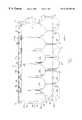
- FIG. 1is a front elevation of a panel illustrating the relatively wide rectangular apertures and the tongues along the right edge, and also showing in dashed lines both the relatively narrow tabs near the lower edge, and the tabs on the rear of the panel near the left side that define the grooves along the left edge.
- FIG. 2is a rear elevation of a panel illustrating the relatively wide rectangular apertures, the tongues along the left edge, the relatively narrow tabs near the lower edge, and the groove connections along the right edge.
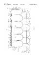
- FIG. 3is a sectional drawing taken through the line 3 — 3 of FIG. 1 and viewed in the direction of the arrows.
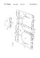
- FIG. 4is a perspective rear view of a plurality of panels installed in an interfitting manner, illustrating the side tongue-and-groove attachments.
- FIG. 5is a plan view of a plurality of panels installed on a wall surface, with one panel shown separated from the others in a position illustrating a first method of installation.
- FIG. 6is a plan view of a plurality of panels installed on a wall surface, with one panel shown separated from the others in a position illustrating a second method of installation.
- the present inventionprovides injection molded exterior siding panels that facilitate easier installation by incorporating relatively wide rectangular apertures along the top of each panel to receive relatively narrow complimentary tabs spaced on the lower rear of an overlapping second panel, as well as a side attachment comprising a discontinuous tongue-and groove-apparatus.
- FIGS. 1 and 2The structure of the inventive panels is depicted in FIGS. 1 and 2, showing front and rear elevations of such a panel.
- Panel 10comprises top portion 12 , bottom portion 14 , right side portion 16 , and left side portion 18 .
- decorative elements 24are arranged in upper row 26 and lower row 28 .
- further embodiments in the form of panelscomprising only a single row of decorative elements 24 or three or more rows of decorative elements 24 may be designed in accordance with the present invention as hereinafter described.
- upper row 26 and lower row 28 of decorative elements 24are offset, resulting in a discontinuous left edge portions 30 and a discontinuous right edge portions 32 of panel 10 .
- Decorative elements 24which are depicted in FIGS.
- decorative elements 24may also comprise simulated cedar shake shingles or other types of shingles with simulated wood grain finish. Between adjacent decorative elements 24 are gaps 34 of uniform thickness. Decorative elements 24 are disposed such that the bottom portion 36 of each decorative element 24 is spaced further away from the wall surface (not shown) than the top portion 38 of each decorative element 24 when panel 10 is installed. This results in the appearance of overlap of each successive upper row 26 of decorative elements 24 over an adjacent lower row 28 of decorative elements 24 . As may be seen in FIG. 2, support ridges 40 between each decorative element 24 on the upper row 26 fit against the wall surface (not shown) and support panel 10 against the wall surface.
- Panel 10is manufactured using a customary injection molding process, and comprises a single piece of injection molded material, for example polypropylene or polyvinyl chloride (PVC).
- panel 10is formed of a composition that will provide a firm, rigid panel resistant to impacts on front side 20 , yet is able to accommodate flexing, such as bending or bowing.
- Panel 10is also formed of a non-brittle composition that is resistant to cracking or fracturing, and therefore able to withstand cutting along horizontal, vertical, or diagonal directions during installation.
- one suitable materialincludes polypropylene, a blend of copolymer and homopolymer resins, filled with calcium carbonate and ultraviolet (UV) stabilizer.
- top portion 12 of panel 10comprises mounting strip 42 , which is disposed between top edge 44 and aperture ledge/edge 46 .
- Spaced at intervals along the mounting strip 42are nailing apertures 48 .
- Nailing apertures 48are herein illustrated in an elongated oval shape. However, nailing apertures 48 may take any shape, and need only be wider in the horizontal direction than the width of a nail (not shown) in order to accommodate the horizontal shifting movement of installed panels 10 that is generally associated with thermal expansion or the settling of the underlying wall surface.
- Nailing apertures 48are bordered on the rear side 22 of panel 10 by rings 50 which are integrally formed with panel 10 and abut the wall surface.
- Rings 50prevent the heads of the nails from directly pinning mounting strip 42 to the wall surface along its entire length in a flush manner when nailed into place during installation. Such pinning of mounting strip 42 to the wall surface may result in panel 10 tearing from the underlying wall surface around the head of the nail.
- Rectangular apertures 52are disposed below nail apertures 48 and intersect aperture edge 46 such that rectangular apertures 52 are partially disposed both within mounting strip 42 and upper row 26 decorative elements 24 . Rectangular apertures 52 are spaced along top portion 12 of panel 10 such that rectangular apertures 52 are centered with respect to gaps 34 between decorative elements 24 .
- lateral ridge 54is disposed along the bottom portion 14 of panel 10 , and is integrally formed with panel 10 .
- Tabs 56are spaced along lateral ridge 54 at the center of each decorative element 24 in lower row 28 .
- Tabs 56are integrally formed with lateral ridge 54 in a horizontal row and depend downward from lateral ridge 54 .
- Tab supports 58are integrally formed with tabs 56 and lateral ridge 54 and prevent tabs 56 from bending around the pivot of lateral ridge 54 toward the rear side 22 of panel 10 .
- Tabs 56are tapered slightly toward their ends 58 and are narrower than rectangular apertures 52 . More specifically, tabs 56 are usually about one half the width of rectangular apertures 52 .
- tabs 56 and rectangular apertures 52provide a free lateral space in either horizontal direction. Therefore, when tabs 56 of a first panel are inserted into rectangular apertures 52 of a second panel, the free lateral space provides positioning relief for the mounting of panel 10 onto previously installed panels.
- vertical ridges 60are disposed along the rear side 22 of panel 10 proximal to left edge 30 .
- the area between vertical ridges 60 and left edge 30defines left overlap portion 62 .
- integralally formed with vertical ridges 60are tabs 64 which extend horizontally from vertical ridges 60 toward left edge 30 .
- Tabs 64 , together with left overlap portion 62define grooves 68 with open ends facing left edge 30 .
- Tongues 70extend from the discontinuous right edge 32 .
- Tongues 70contain tongue channels 72 which open facing the front side 20 of panel 10 .
- Tongues 70also contain tongue support ridges 74 which abut the wall surface (not shown) and support tongues 70 against the wall surface.
- Tongues 70are longer than the corresponding tabs 64 , which, together with left overlap portion 62 define grooves 68 .
- rectangular apertures 52are disposed through panel 10 at a generally downward angle toward the wall surface (not shown). This downward angle allows tabs 56 to be inserted both through and downward into rectangular apertures 52 in a single motion, as opposed to first inserting tabs 56 through rectangular apertures 52 followed by a second motion of tabs 56 downward behind the rear side 22 of panel 10 . Nailing apertures 48 surrounded by rings 50 which abut the wall surface are also shown, disposed above rectangular apertures 52 . Support ridges 40 are disposed between the decorative elements 24 of upper row 26 and support panel 10 against wall the surface (not shown). Tabs 56 are integrally formed with lateral ridge 54 and depend downward from the center of each decorative element 24 on the lower row 28 .
- FIG. 4an adjoining pair of panels is shown as they would be attached in accordance with the present invention.
- Tabs 56are inserted through rectangular apertures 52 and are disposed against the rear side 22 of panel 10 .
- Tongues 70are inserted within grooves 68 . Similar to the connections of tabs 56 through rectangular apertures 52 , the connections between tongues 70 and grooves 68 can accommodate horizontal movement while still maintaining an interlocking connection.
- Tongue support ridges 74abut the wall surface (not shown) and support tongues 70 against the wall surface (not shown).
- Support ridges 40also abut the wall surface and support panel 10 against the wall surface.
- End portions 76 of mounting strips 42are offset on opposite ends of each mounting strip 42 in order to facilitate an overlapping relation.
- End portions 76 of mounting strips 42also contain nailing apertures 48 which may be overlapped to receive a mounting nail driven through both nailing apertures 48 .
- each panelmay comprise horizontal connections of tongues similar to tongues 70 mounted to and extending from the mounting strip 42 fitting within grooves similar to grooves 68 defined by tabs similar to tabs 64 mounted on the rear of lower row 28 of decorative elements 24 .
- Such a panelmay further comprise vertical connections of relatively narrow tabs similar to tabs 64 mounted on the rear of the panel proximal to the sides of both the upper row 26 and lower row 28 of decorative elements 24 , fitting within rectangular apertures similar to rectangular apertures 52 disposed at intervals through left overlap portion 62 , the aforementioned embodiment not departing from the scope of the present invention.
- a starter strip(essentially comprising the structure of mounting strip 42 ), is nailed into place along the bottom of wall surface 78 .
- the starter stripis comprised of an upper portion, similar to mounting strip 42 and a lower portion accommodating rectangular apertures similar to rectangular apertures 52 .
- an initial panel 80identical to panel 10 as illustrated in FIGS. 1, 2 , 3 , and 4 , is cut vertically to fit flush against the left edge of the wall surface.
- the location on initial panel 80 at which that panel is cut verticallyis determined by the discretion of the installer, as initial panel 80 may be cut at any location.
- Initial panel 80is mounted on the starter strip by inserting the tabs on the rear of initial panel 80 through the rectangular apertures within the starter strip, then nailing initial panel 80 into place by driving a plurality of nails through nailing apertures of initial panel 80 . Additional panels are then installed along the starter strip to effect a first course 90 of installed panels.
- a first method of installation of panel 86is illustrated.
- the relatively narrow tabs 56 on the rear of the bottom portion 14 of panel 10are inserted vertically downward through rectangular apertures 52 of vertically adjacent, previously installed panel 82 (and also panel 80 ).
- the positioning relief provided by the difference in width between tabs 56 and rectangular apertures 52aids this first step of installation.
- panel 86may rest upon panel 82 in a partially overlapped position, and it may be seen that side grooves 68 of panel 86 are aligned horizontally with the corresponding tongues 70 of horizontally adjacent, previously installed panel 84 .
- Panel 86is then shifted directly horizontally in the direction of arrow A, thereby engaging grooves 68 of panel 86 around tongues 70 of panel 84 .
- Panel 86is then permanently secured by driving nails through nailing apertures 48 disposed within mounting strip 42 of panel 86 .
- FIG. 6a second method of installation of panel 86 ′ is illustrated.
- grooves 68 of panel 10are initially partially engaged around the corresponding tongues of a horizontally adjacent, previously installed panel 84 .
- Panel 86 ′is then rotated in a clockwise direction in the direction of arrow B, simultaneously inserting the relatively narrow tabs 56 of panel 86 ′ through the rectangular apertures 52 of vertically adjacent, previously installed panel 82 , while simultaneously completing the engagement of grooves 68 of panel 68 ′ around the tongues 70 of panel 82 .
- tabs 56are about one inch (1′′) wide and apertures 52 are about three inches (3′′) wide.
- the material of panels 10is: polypropylene, which may include one or more of the following additives: calcium carbonate and UV stabilizer.
- the panel sizein the exemplary embodiment, has dimensions of approximately thirty-five and one half inches (35 1 ⁇ 2′′) breath by approximately sixteen and one half inches (16 1 ⁇ 2′′) height by approximately seven sixty-fourths inches ( ⁇ fraction (7/64) ⁇ ′′) wall thickness.
Landscapes
- Engineering & Computer Science (AREA)
- Architecture (AREA)
- Civil Engineering (AREA)
- Structural Engineering (AREA)
- Life Sciences & Earth Sciences (AREA)
- Wood Science & Technology (AREA)
- Finishing Walls (AREA)
Abstract
Description
Claims (28)
Priority Applications (2)
| Application Number | Priority Date | Filing Date | Title |
|---|---|---|---|
| US09/307,457US6336303B1 (en) | 1999-05-07 | 1999-05-07 | Injection molded exterior siding panel with positioning relief and method of installation |
| CA002302598ACA2302598C (en) | 1999-05-07 | 2000-03-22 | Injection molded exterior siding panel with positioning relief and method of installation |
Applications Claiming Priority (1)
| Application Number | Priority Date | Filing Date | Title |
|---|---|---|---|
| US09/307,457US6336303B1 (en) | 1999-05-07 | 1999-05-07 | Injection molded exterior siding panel with positioning relief and method of installation |
Publications (1)
| Publication Number | Publication Date |
|---|---|
| US6336303B1true US6336303B1 (en) | 2002-01-08 |
Family
ID=23189860
Family Applications (1)
| Application Number | Title | Priority Date | Filing Date |
|---|---|---|---|
| US09/307,457Expired - Fee RelatedUS6336303B1 (en) | 1999-05-07 | 1999-05-07 | Injection molded exterior siding panel with positioning relief and method of installation |
Country Status (2)
| Country | Link |
|---|---|
| US (1) | US6336303B1 (en) |
| CA (1) | CA2302598C (en) |
Cited By (36)
| Publication number | Priority date | Publication date | Assignee | Title |
|---|---|---|---|---|
| US20020189187A1 (en)* | 1999-09-08 | 2002-12-19 | Bryant David A. | Plastic siding panel |
| US6526717B2 (en)* | 1998-05-07 | 2003-03-04 | Pacific International Tool & Shear, Ltd. | Unitary modular shake-siding panels, and methods for making and using such shake-siding panels |
| US6776150B2 (en) | 1998-03-06 | 2004-08-17 | Shear Technologies, Inc. | Method and apparatus for cutting fiber-cement material along an arcuate path |
| US20040159062A1 (en)* | 2002-05-10 | 2004-08-19 | Nailite International | Decorative wall covering with upward movement panel interlock system |
| US20040216417A1 (en)* | 2003-01-15 | 2004-11-04 | Thomas Wegman | Shingle, in particular roof shingle |
| US20050102946A1 (en)* | 2003-10-30 | 2005-05-19 | Stucky David J. | Siding panel tab and slot joint |
| US20050193674A1 (en)* | 2004-02-13 | 2005-09-08 | Gerald Hatkoff | Locking laps for vinyl siding |
| US20060026921A1 (en)* | 2004-08-05 | 2006-02-09 | Associated Materials, Inc., D/B/A Alside | Splicer for siding panel assembly |
| US20060026908A1 (en)* | 2004-08-05 | 2006-02-09 | Gregori Werner K H | Simulated wood shingles with multiple alignment features |
| WO2007050226A3 (en)* | 2005-10-26 | 2007-06-21 | Wilbert Inc | Method and apparatus for molding an interlocking tab in a single molding and formatting step |
| US20080034699A1 (en)* | 2006-08-09 | 2008-02-14 | Epoch Composite Products, Inc. | Roofing product possessing thermal expansion relief characteristics |
| US20080083186A1 (en)* | 2006-10-04 | 2008-04-10 | Novik, Inc. | Roofing panels and roofing system employing the same |
| US20080098683A1 (en)* | 2006-10-27 | 2008-05-01 | Nailite International | Decorative wall covering with improved interlock system |
| US20080155922A1 (en)* | 2006-12-29 | 2008-07-03 | Wolf David H | Panelized veneer with backer-to-backer locators |
| US20080155921A1 (en)* | 2006-12-29 | 2008-07-03 | Wolf David H | Veneer panel |
| US20090100779A1 (en)* | 2007-10-23 | 2009-04-23 | Duron Plastics Limited | Plastic roof shingle |
| US20090241458A1 (en)* | 2008-03-27 | 2009-10-01 | Ko Das | Siding Panel Assembly With Splicing Member and Insulating Panel |
| US20090260307A1 (en)* | 2005-12-23 | 2009-10-22 | Flooring Industries Limited, Sarl | Floor Panel and Method for Manufacturing Such Floor Panel |
| US20090293401A1 (en)* | 2008-06-02 | 2009-12-03 | Alcoa Home Exteriors, Inc. | Panel For Covering A Wall With Uplock Engagement |
| USD610721S1 (en)* | 2006-07-27 | 2010-02-23 | Naizil S.P.A. | Pattern for awning |
| US20100088988A1 (en)* | 2008-10-15 | 2010-04-15 | Novik, Inc. | Polymer building products |
| US20100313501A1 (en)* | 2009-06-10 | 2010-12-16 | Gangemi Ronald J | Roof mounting bracket for photovoltaic power generation system |
| US20100313499A1 (en)* | 2009-06-10 | 2010-12-16 | Gangemi Ronald J | Roof mounting bracket for photovoltaic power generation system |
| US20110072755A1 (en)* | 2008-07-29 | 2011-03-31 | Trevor John Wakefield | Interlockable tiles |
| US20110154767A1 (en)* | 2007-11-01 | 2011-06-30 | Matti Perttula | Roof element |
| USD648038S1 (en) | 2010-06-04 | 2011-11-01 | Novik, Inc. | Shingle |
| US8209938B2 (en) | 2010-03-08 | 2012-07-03 | Novik, Inc. | Siding and roofing panel with interlock system |
| US20150000538A1 (en)* | 2011-12-05 | 2015-01-01 | Arman Emami | Grill device |
| US8950135B2 (en) | 2012-12-19 | 2015-02-10 | Novik Inc. | Corner assembly for siding and roofing coverings and method for covering a corner using same |
| US9091086B2 (en) | 2013-01-21 | 2015-07-28 | Tapco International Corporation | Siding panel system with randomized elements |
| US9267296B2 (en)* | 2014-06-05 | 2016-02-23 | Tapco International Corporation | Multi-tile roofing or siding system |
| US9388565B2 (en) | 2012-12-20 | 2016-07-12 | Novik Inc. | Siding and roofing panels and method for mounting same |
| US20170022719A1 (en)* | 2015-05-27 | 2017-01-26 | Novik Inc. | Covering panel with simulated building elements |
| US9903124B2 (en) | 2008-02-06 | 2018-02-27 | Boral Stone Products Llc | Prefabricated wall panel with tongue and groove construction |
| USRE47694E1 (en) | 2012-08-08 | 2019-11-05 | Boral Stone Products Llc | Wall panel |
| US11332943B2 (en) | 2019-10-08 | 2022-05-17 | D.A. Distribution Inc. | Wall covering with adjustable spacing |
Citations (24)
| Publication number | Priority date | Publication date | Assignee | Title |
|---|---|---|---|---|
| US3309831A (en) | 1964-12-09 | 1967-03-21 | Misch Arthur | Plastic shingle with interfitting means |
| US4096011A (en) | 1976-12-10 | 1978-06-20 | Aegean Industries, Inc. | Method of manufacturing exterior siding |
| US4201024A (en) | 1977-01-17 | 1980-05-06 | Lockheed Corporation | Plastic/composite structural panel |
| US4229916A (en) | 1978-09-29 | 1980-10-28 | White Robert W | Building panel |
| US4251967A (en) | 1978-03-27 | 1981-02-24 | Hoofe Iii William J | Weatherproof roofing panels |
| US4290248A (en) | 1975-01-06 | 1981-09-22 | William James Kemerer | Continuous process for forming products from thermoplastic polymeric material having three-dimensional patterns and surface textures |
| US4308702A (en) | 1976-12-28 | 1982-01-05 | Gaf Corporation | Plastic building panel and method for making same |
| US4476661A (en) | 1981-12-14 | 1984-10-16 | Hoofe Iii William J | Clip locked roofing and siding panels |
| US4598522A (en) | 1984-06-22 | 1986-07-08 | Hoofe William J Iii | Interlocking panels |
| US4680911A (en) | 1986-05-21 | 1987-07-21 | Davis Richard A | Decorative wall covering |
| US4953537A (en) | 1989-09-18 | 1990-09-04 | Inner Solar Roof System, Inc. | Barrel-shaped solar roofing element and method for its manufacture |
| US5076037A (en) | 1990-03-02 | 1991-12-31 | Nailite International | Decorative wall cover and method of installation |
| US5224318A (en) | 1991-02-19 | 1993-07-06 | Kemerer W James | Molded protective exterior weather-resistant building panels |
| US5249402A (en) | 1991-04-09 | 1993-10-05 | Crick Dallas M | Decorative wall covering |
| US5295339A (en) | 1992-08-10 | 1994-03-22 | Manner Value Plastic, Inc. | Simulated individual self-venting overlapping plastic shake |
| US5347784A (en) | 1992-12-28 | 1994-09-20 | Nailite International | Decorative wall covering with improved interlock and corner construction |
| US5388381A (en) | 1993-01-21 | 1995-02-14 | General Electric Company | Interlocking building panel |
| US5461839A (en) | 1993-12-22 | 1995-10-31 | Certainteed Corporation | Reinforced exterior siding |
| US5600971A (en) | 1996-04-15 | 1997-02-11 | Suk; Whang K. | Roof plate mounting assembly |
| US5615523A (en) | 1995-04-24 | 1997-04-01 | Owens-Corning Fiberglas Technology, Inc. | Roof having resinous shingles |
| US5630305A (en) | 1991-08-26 | 1997-05-20 | Hlasnicek; Richard S. | Surface covering unit methods of use and manufacture |
| US5636481A (en) | 1993-02-08 | 1997-06-10 | Royal Building Systems (Cdn) Limited | Molded cladding for building structures |
| US5711126A (en) | 1996-05-13 | 1998-01-27 | Owens-Corning Fiberglass Technology, Inc. | Resinous angled shingles for roof ridge lines |
| US5735099A (en) | 1995-10-23 | 1998-04-07 | Western Log And Lumber | Log siding |
- 1999
- 1999-05-07USUS09/307,457patent/US6336303B1/ennot_activeExpired - Fee Related
- 2000
- 2000-03-22CACA002302598Apatent/CA2302598C/ennot_activeExpired - Fee Related
Patent Citations (25)
| Publication number | Priority date | Publication date | Assignee | Title |
|---|---|---|---|---|
| US3309831A (en) | 1964-12-09 | 1967-03-21 | Misch Arthur | Plastic shingle with interfitting means |
| US4290248A (en) | 1975-01-06 | 1981-09-22 | William James Kemerer | Continuous process for forming products from thermoplastic polymeric material having three-dimensional patterns and surface textures |
| US4096011A (en) | 1976-12-10 | 1978-06-20 | Aegean Industries, Inc. | Method of manufacturing exterior siding |
| US4308702A (en) | 1976-12-28 | 1982-01-05 | Gaf Corporation | Plastic building panel and method for making same |
| US4201024A (en) | 1977-01-17 | 1980-05-06 | Lockheed Corporation | Plastic/composite structural panel |
| US4251967A (en) | 1978-03-27 | 1981-02-24 | Hoofe Iii William J | Weatherproof roofing panels |
| US4229916A (en) | 1978-09-29 | 1980-10-28 | White Robert W | Building panel |
| US4476661A (en) | 1981-12-14 | 1984-10-16 | Hoofe Iii William J | Clip locked roofing and siding panels |
| US4598522A (en) | 1984-06-22 | 1986-07-08 | Hoofe William J Iii | Interlocking panels |
| US4680911A (en) | 1986-05-21 | 1987-07-21 | Davis Richard A | Decorative wall covering |
| US4953537A (en) | 1989-09-18 | 1990-09-04 | Inner Solar Roof System, Inc. | Barrel-shaped solar roofing element and method for its manufacture |
| US5076037A (en) | 1990-03-02 | 1991-12-31 | Nailite International | Decorative wall cover and method of installation |
| US5224318A (en) | 1991-02-19 | 1993-07-06 | Kemerer W James | Molded protective exterior weather-resistant building panels |
| US5249402A (en) | 1991-04-09 | 1993-10-05 | Crick Dallas M | Decorative wall covering |
| US5630305A (en) | 1991-08-26 | 1997-05-20 | Hlasnicek; Richard S. | Surface covering unit methods of use and manufacture |
| US5295339A (en) | 1992-08-10 | 1994-03-22 | Manner Value Plastic, Inc. | Simulated individual self-venting overlapping plastic shake |
| US5347784A (en) | 1992-12-28 | 1994-09-20 | Nailite International | Decorative wall covering with improved interlock and corner construction |
| US5388381A (en) | 1993-01-21 | 1995-02-14 | General Electric Company | Interlocking building panel |
| US5636481A (en) | 1993-02-08 | 1997-06-10 | Royal Building Systems (Cdn) Limited | Molded cladding for building structures |
| US5461839A (en) | 1993-12-22 | 1995-10-31 | Certainteed Corporation | Reinforced exterior siding |
| US5526627A (en) | 1993-12-22 | 1996-06-18 | Certainteed Corporation | Reinforced exterior siding |
| US5615523A (en) | 1995-04-24 | 1997-04-01 | Owens-Corning Fiberglas Technology, Inc. | Roof having resinous shingles |
| US5735099A (en) | 1995-10-23 | 1998-04-07 | Western Log And Lumber | Log siding |
| US5600971A (en) | 1996-04-15 | 1997-02-11 | Suk; Whang K. | Roof plate mounting assembly |
| US5711126A (en) | 1996-05-13 | 1998-01-27 | Owens-Corning Fiberglass Technology, Inc. | Resinous angled shingles for roof ridge lines |
Cited By (58)
| Publication number | Priority date | Publication date | Assignee | Title |
|---|---|---|---|---|
| US6776150B2 (en) | 1998-03-06 | 2004-08-17 | Shear Technologies, Inc. | Method and apparatus for cutting fiber-cement material along an arcuate path |
| US7575701B2 (en) | 1998-05-07 | 2009-08-18 | Shear Tech, Inc. | Method of fabricating shake panels |
| US6526717B2 (en)* | 1998-05-07 | 2003-03-04 | Pacific International Tool & Shear, Ltd. | Unitary modular shake-siding panels, and methods for making and using such shake-siding panels |
| US20030110729A1 (en)* | 1998-05-07 | 2003-06-19 | Kurt Waggoner | Unitary modular shake-siding panels, and methods for making and using such shake-siding panels |
| US6715250B2 (en)* | 1999-09-08 | 2004-04-06 | Alcoa Inc. | Plastic siding panel |
| US20020189187A1 (en)* | 1999-09-08 | 2002-12-19 | Bryant David A. | Plastic siding panel |
| US6955019B2 (en)* | 2002-05-10 | 2005-10-18 | Nailite International | Decorative wall covering with upward movement panel interlock system |
| US20040159062A1 (en)* | 2002-05-10 | 2004-08-19 | Nailite International | Decorative wall covering with upward movement panel interlock system |
| US7263809B2 (en)* | 2003-01-15 | 2007-09-04 | Sls Kunstsoffverarbeitung Gmbh & Co. Kg | Shingle, in particular roof shingle |
| US20040216417A1 (en)* | 2003-01-15 | 2004-11-04 | Thomas Wegman | Shingle, in particular roof shingle |
| US20050102946A1 (en)* | 2003-10-30 | 2005-05-19 | Stucky David J. | Siding panel tab and slot joint |
| US7207145B2 (en)* | 2003-10-30 | 2007-04-24 | Certainteed Corporation | Siding panel tab and slot joint |
| US20050193674A1 (en)* | 2004-02-13 | 2005-09-08 | Gerald Hatkoff | Locking laps for vinyl siding |
| US20060026921A1 (en)* | 2004-08-05 | 2006-02-09 | Associated Materials, Inc., D/B/A Alside | Splicer for siding panel assembly |
| US20060026908A1 (en)* | 2004-08-05 | 2006-02-09 | Gregori Werner K H | Simulated wood shingles with multiple alignment features |
| US7478507B2 (en)* | 2004-08-05 | 2009-01-20 | Associated Materials, Llc. | Splicer and siding panel assembly |
| WO2007050226A3 (en)* | 2005-10-26 | 2007-06-21 | Wilbert Inc | Method and apparatus for molding an interlocking tab in a single molding and formatting step |
| US8316604B2 (en)* | 2005-12-23 | 2012-11-27 | Flooring Industries Limited, Sarl | Floor panel and method for manufacturing such floor panel |
| US20090260307A1 (en)* | 2005-12-23 | 2009-10-22 | Flooring Industries Limited, Sarl | Floor Panel and Method for Manufacturing Such Floor Panel |
| USD610721S1 (en)* | 2006-07-27 | 2010-02-23 | Naizil S.P.A. | Pattern for awning |
| US20080034699A1 (en)* | 2006-08-09 | 2008-02-14 | Epoch Composite Products, Inc. | Roofing product possessing thermal expansion relief characteristics |
| US7631461B2 (en)* | 2006-08-09 | 2009-12-15 | Epoch Composite Products, Inc. | Roofing product possessing thermal expansion relief characteristics |
| US7735287B2 (en) | 2006-10-04 | 2010-06-15 | Novik, Inc. | Roofing panels and roofing system employing the same |
| US20080083186A1 (en)* | 2006-10-04 | 2008-04-10 | Novik, Inc. | Roofing panels and roofing system employing the same |
| US7980037B2 (en)* | 2006-10-27 | 2011-07-19 | Exteria Building Products, Llc | Decorative wall covering with improved interlock system |
| US8074417B2 (en) | 2006-10-27 | 2011-12-13 | Exteria Building Products, Llc | Decorative wall covering with improved interlock system |
| US20080098683A1 (en)* | 2006-10-27 | 2008-05-01 | Nailite International | Decorative wall covering with improved interlock system |
| US20080155921A1 (en)* | 2006-12-29 | 2008-07-03 | Wolf David H | Veneer panel |
| US20080155922A1 (en)* | 2006-12-29 | 2008-07-03 | Wolf David H | Panelized veneer with backer-to-backer locators |
| US8042309B2 (en)* | 2006-12-29 | 2011-10-25 | Boral Stone Products Llc | Panelized veneer with backer-to-backer locators |
| US20090100779A1 (en)* | 2007-10-23 | 2009-04-23 | Duron Plastics Limited | Plastic roof shingle |
| US8806827B2 (en)* | 2007-11-01 | 2014-08-19 | Rautaruukki Oyj | Roof element |
| US20110154767A1 (en)* | 2007-11-01 | 2011-06-30 | Matti Perttula | Roof element |
| US10557273B2 (en) | 2008-02-06 | 2020-02-11 | Boral Stone Products Llc | Prefabricated wall panel with tongue and groove construction |
| US10378216B2 (en)* | 2008-02-06 | 2019-08-13 | Boral Stone Products Llc | Prefabricated wall panel with tongue and groove construction |
| US9903124B2 (en) | 2008-02-06 | 2018-02-27 | Boral Stone Products Llc | Prefabricated wall panel with tongue and groove construction |
| US10329775B2 (en) | 2008-02-06 | 2019-06-25 | Boral Ip Holdings (Australia) Pty Limited | Method of forming a wall panel |
| US11891814B2 (en) | 2008-02-06 | 2024-02-06 | Westlake Royal Stone Llc | Prefabricated wall panel with tongue and groove construction |
| US20180135310A1 (en)* | 2008-02-06 | 2018-05-17 | Boral Stone Products Llc | Prefabricated wall panel with tongue and groove construction |
| US20090241458A1 (en)* | 2008-03-27 | 2009-10-01 | Ko Das | Siding Panel Assembly With Splicing Member and Insulating Panel |
| US20090293401A1 (en)* | 2008-06-02 | 2009-12-03 | Alcoa Home Exteriors, Inc. | Panel For Covering A Wall With Uplock Engagement |
| US8359804B2 (en)* | 2008-07-29 | 2013-01-29 | Green Ip Box Limited | Interlockable tiles |
| US20110072755A1 (en)* | 2008-07-29 | 2011-03-31 | Trevor John Wakefield | Interlockable tiles |
| US8020353B2 (en)* | 2008-10-15 | 2011-09-20 | Novik, Inc. | Polymer building products |
| US20100088988A1 (en)* | 2008-10-15 | 2010-04-15 | Novik, Inc. | Polymer building products |
| US20100313499A1 (en)* | 2009-06-10 | 2010-12-16 | Gangemi Ronald J | Roof mounting bracket for photovoltaic power generation system |
| US20100313501A1 (en)* | 2009-06-10 | 2010-12-16 | Gangemi Ronald J | Roof mounting bracket for photovoltaic power generation system |
| US8209938B2 (en) | 2010-03-08 | 2012-07-03 | Novik, Inc. | Siding and roofing panel with interlock system |
| USD648038S1 (en) | 2010-06-04 | 2011-11-01 | Novik, Inc. | Shingle |
| US20150000538A1 (en)* | 2011-12-05 | 2015-01-01 | Arman Emami | Grill device |
| USRE47694E1 (en) | 2012-08-08 | 2019-11-05 | Boral Stone Products Llc | Wall panel |
| US8950135B2 (en) | 2012-12-19 | 2015-02-10 | Novik Inc. | Corner assembly for siding and roofing coverings and method for covering a corner using same |
| US9388565B2 (en) | 2012-12-20 | 2016-07-12 | Novik Inc. | Siding and roofing panels and method for mounting same |
| US9091086B2 (en) | 2013-01-21 | 2015-07-28 | Tapco International Corporation | Siding panel system with randomized elements |
| US9267296B2 (en)* | 2014-06-05 | 2016-02-23 | Tapco International Corporation | Multi-tile roofing or siding system |
| US20170022719A1 (en)* | 2015-05-27 | 2017-01-26 | Novik Inc. | Covering panel with simulated building elements |
| US10184254B2 (en)* | 2015-05-27 | 2019-01-22 | Derby Building Products Inc. | Covering panel with simulated building elements |
| US11332943B2 (en) | 2019-10-08 | 2022-05-17 | D.A. Distribution Inc. | Wall covering with adjustable spacing |
Also Published As
| Publication number | Publication date |
|---|---|
| CA2302598C (en) | 2004-06-01 |
| CA2302598A1 (en) | 2000-11-07 |
Similar Documents
| Publication | Publication Date | Title |
|---|---|---|
| US6336303B1 (en) | Injection molded exterior siding panel with positioning relief and method of installation | |
| US5694728A (en) | Vinyl siding system | |
| US7240461B1 (en) | Siding panels for wall coverings | |
| US6715250B2 (en) | Plastic siding panel | |
| US6224701B1 (en) | Molded plastic siding panel | |
| US7654050B2 (en) | Corner trim piece for siding | |
| US4320613A (en) | Profiled insulating underboard | |
| US6955019B2 (en) | Decorative wall covering with upward movement panel interlock system | |
| CA1138172A (en) | Horizontal siding panel system with vertical stringers | |
| US5224318A (en) | Molded protective exterior weather-resistant building panels | |
| US4327528A (en) | Insulated siding system | |
| US6301856B1 (en) | Siding panel with interlock | |
| US6684587B2 (en) | Cedar impression siding corner | |
| US6786015B2 (en) | Log wall siding system | |
| US7698864B2 (en) | Bonded siding panels | |
| US7228665B2 (en) | Roof and wall covering with improved corner construction | |
| US7478507B2 (en) | Splicer and siding panel assembly | |
| US20070107356A1 (en) | Staggered look shake siding panel with improved locking mechanism | |
| AU2006248112A1 (en) | Weatherproof lap siding system | |
| US20050257475A1 (en) | Thin brick veneer panel | |
| JPH073957A (en) | Panel for interlock type construction | |
| US20080148671A1 (en) | Soffit and fascia siding system | |
| US20080038508A1 (en) | Deck system | |
| WO2005099418A2 (en) | Shingled siding unit | |
| US7743571B2 (en) | Injection moldable composite gable vent |
Legal Events
| Date | Code | Title | Description |
|---|---|---|---|
| AS | Assignment | Owner name:ATLANTIS PLASTICS, INC., INDIANA Free format text:ASSIGNMENT OF ASSIGNORS INTEREST;ASSIGNORS:VANDEMAN, RONALD L.;SAUER, TIMOTHY M.;REEL/FRAME:009955/0254 Effective date:19990505 | |
| AS | Assignment | Owner name:GENERAL ELECTRIC CAPITAL CORPORATION, ILLINOIS Free format text:SECURITY INTEREST;ASSIGNOR:ATLANTIS PLASTICS, INC.;REEL/FRAME:014215/0879 Effective date:20021227 | |
| AS | Assignment | Owner name:MERRILL LYNCH CAPITAL, A DIVISION OF MERRILL LYNCH Free format text:SECURITY AGREEMENT;ASSIGNOR:ATLANTIS PLASTICS, INC.;REEL/FRAME:015829/0091 Effective date:20050322 Owner name:ATLANTIS PLASTICS, INC., GEORGIA Free format text:RELEASE OF SECURITY INTEREST;ASSIGNOR:GENERAL ELECTRIC CAPITAL CORPORATION, AS AGENT;REEL/FRAME:015829/0099 Effective date:20050322 | |
| AS | Assignment | Owner name:THE BANK OF NEW YORK, AS AGENT, TEXAS Free format text:SECURITY AGREEMENT;ASSIGNOR:ATLANTIS PLASTICS, INC.;REEL/FRAME:015851/0489 Effective date:20050322 Owner name:THE BANK OF NEW YORK, AS AGENT,TEXAS Free format text:SECURITY AGREEMENT;ASSIGNOR:ATLANTIS PLASTICS, INC.;REEL/FRAME:015851/0489 Effective date:20050322 | |
| REMI | Maintenance fee reminder mailed | ||
| LAPS | Lapse for failure to pay maintenance fees | ||
| STCH | Information on status: patent discontinuation | Free format text:PATENT EXPIRED DUE TO NONPAYMENT OF MAINTENANCE FEES UNDER 37 CFR 1.362 | |
| FP | Expired due to failure to pay maintenance fee | Effective date:20060108 | |
| AS | Assignment | Owner name:CUSTOM PLASTIC SOLUTIONS, LLC, KENTUCKY Free format text:UNITED STATES BANKRUPTCY COURT SALE ORDER;ASSIGNOR:ATLANTIS PLASTICS, INC.;REEL/FRAME:021849/0257 Effective date:20081006 Owner name:CUSTOM PLASTIC SOLUTIONS, LLC, KENTUCKY Free format text:ASSIGNMENT OF ASSIGNORS INTEREST;ASSIGNOR:ATLANTIS PLASTICS, INC.;REEL/FRAME:021849/0500 Effective date:20081010 Owner name:CUSTOM PLASTIC FINCO, LLC, NEW YORK Free format text:SECURITY AGREEMENT;ASSIGNOR:CUSTOM PLASTIC SOLUTIONS, LLC;REEL/FRAME:021849/0579 Effective date:20081010 Owner name:FORTIS PLASTICS, LLC, KENTUCKY Free format text:MERGER;ASSIGNORS:UNIQUE MOLDED PRODUCTS, INC.;CUSTOM PLASTIC SOLUTIONS, LLC;REEL/FRAME:021849/0868 Effective date:20081020 Owner name:CUSTOM PLASTIC SOLUTIONS, LLC,KENTUCKY Free format text:UNITED STATES BANKRUPTCY COURT SALE ORDER;ASSIGNOR:ATLANTIS PLASTICS, INC.;REEL/FRAME:021849/0257 Effective date:20081006 Owner name:CUSTOM PLASTIC SOLUTIONS, LLC,KENTUCKY Free format text:ASSIGNMENT OF ASSIGNORS INTEREST;ASSIGNOR:ATLANTIS PLASTICS, INC.;REEL/FRAME:021849/0500 Effective date:20081010 Owner name:CUSTOM PLASTIC FINCO, LLC,NEW YORK Free format text:SECURITY AGREEMENT;ASSIGNOR:CUSTOM PLASTIC SOLUTIONS, LLC;REEL/FRAME:021849/0579 Effective date:20081010 Owner name:FORTIS PLASTICS, LLC,KENTUCKY Free format text:MERGER;ASSIGNORS:UNIQUE MOLDED PRODUCTS, INC.;CUSTOM PLASTIC SOLUTIONS, LLC;REEL/FRAME:021849/0868 Effective date:20081020 | |
| AS | Assignment | Owner name:WELLS FARGO BANK, NATIONAL ASSOCIATION, NEW YORK Free format text:SECURITY AGREEMENT;ASSIGNOR:FORTIS PLASTICS, LLC;REEL/FRAME:022043/0875 Effective date:20081226 Owner name:WELLS FARGO BANK, NATIONAL ASSOCIATION,NEW YORK Free format text:SECURITY AGREEMENT;ASSIGNOR:FORTIS PLASTICS, LLC;REEL/FRAME:022043/0875 Effective date:20081226 | |
| AS | Assignment | Owner name:FORTIS PLASTICS, LLC, KENTUCKY Free format text:RELEASE OF SECURITY INTEREST IN PATENTS;ASSIGNOR:CUSTOM PLASTIC FINCO, LLC;REEL/FRAME:022231/0078 Effective date:20081216 Owner name:FORTIS PLASTICS, LLC,KENTUCKY Free format text:RELEASE OF SECURITY INTEREST IN PATENTS;ASSIGNOR:CUSTOM PLASTIC FINCO, LLC;REEL/FRAME:022231/0078 Effective date:20081216 | |
| AS | Assignment | Owner name:FORTIS PLASTICS, LLC, KENTUCKY Free format text:RELEASE OF SECURITY INTEREST IN PATENTS;ASSIGNOR:CUSTOM PLASTIC FINCO, LLC;REEL/FRAME:022259/0117 Effective date:20081216 Owner name:FORTIS PLASTICS, LLC,KENTUCKY Free format text:RELEASE OF SECURITY INTEREST IN PATENTS;ASSIGNOR:CUSTOM PLASTIC FINCO, LLC;REEL/FRAME:022259/0117 Effective date:20081216 | |
| AS | Assignment | Owner name:CUSTOM PLASTIC FINCO, LLC, NEW YORK Free format text:PATENT SECURITY AGREEMENT;ASSIGNOR:FORTIS PLASTICS, LLC;REEL/FRAME:025999/0273 Effective date:20110222 |