US6336042B1 - Reverse link antenna diversity in a wireless telephony system - Google Patents
Reverse link antenna diversity in a wireless telephony systemDownload PDFInfo
- Publication number
- US6336042B1 US6336042B1US09/092,638US9263898AUS6336042B1US 6336042 B1US6336042 B1US 6336042B1US 9263898 AUS9263898 AUS 9263898AUS 6336042 B1US6336042 B1US 6336042B1
- Authority
- US
- United States
- Prior art keywords
- signals
- signal
- distribution network
- wireless
- wireless telephony
- Prior art date
- Legal status (The legal status is an assumption and is not a legal conclusion. Google has not performed a legal analysis and makes no representation as to the accuracy of the status listed.)
- Expired - Lifetime
Links
Images


Classifications
- H—ELECTRICITY
- H04—ELECTRIC COMMUNICATION TECHNIQUE
- H04W—WIRELESS COMMUNICATION NETWORKS
- H04W88/00—Devices specially adapted for wireless communication networks, e.g. terminals, base stations or access point devices
- H04W88/08—Access point devices
- H04W88/085—Access point devices with remote components
Definitions
- the present inventionrelates to wireless telephony equipment, and more particularly to an improved arrangement for providing antenna diversity using remote transceivers in a wireless telephone system that incorporates an existing broadband distribution network, such as a cable television network cable, to carry communication signals between wireless telephones and centrally located telephony equipment.
- an existing broadband distribution networksuch as a cable television network cable
- the prior artteaches the use of an existing broadband network to carry telephony signals between an existing telephone network and a large number of remote transceivers positioned to provide signal coverage in defined cells or sectors.
- the remote transceiverssometimes called Remote Antenna Drivers (RADs)
- RADsRemote Antenna Drivers
- the broadband networksinclude fiber-optic cable, coaxial cable, radio links and combinations of these.
- centrally located equipmentwhich is part of the wireless telephony equipment, and which processes and carries the telephony signals between the telephone network and the broadband distribution network.
- a large number of distributed remote transceiversalso called Remote Antenna Drivers (RADs) are connected to the broadband distribution network.
- the RADscommunicate via the broadband distribution network with Remote Antenna Signal Processors (RASPs), which are a centrally located part of the wireless telephony equipment.
- RASPsRemote Antenna Signal Processors
- the RADs and RASPsuse radio frequency carrier signals to carry telephony signals over the broadband distribution network.
- the RASPsin turn communicate with the telephone network via a Base Telephone Station (BTS).
- BTSBase Telephone Station
- the RADs, RASPs and BTScooperate to carry telephony signals between wireless telephones and the telephone network.
- the RADstransmit radio frequency signals to, and receive radio frequency signals from wireless telephones in a manner well known in the art.
- each RADhas two antennas for receiving telephony signals from wireless telephones, and the signals from all receive antennas are concurrently transmitted over the broadband distribution network to the centrally located RASP and BTS for signal processing before the telephony signals are sent to the telephone network.
- one of the two receive antennasis called the primary receive antenna and the other receive antenna is called the diversity receive antenna.
- each RADrequires duplicate receive circuitry therein, which increases the cost of each RAD.
- each RASPmust process two received telephony signals from each RASP for each wireless telephone. This also requires duplicate circuitry which increases the cost of each RASP.
- the above described need in the wireless telephony artis satisfied by the present invention.
- the Remote Antenna Drivers (RADs) and the Remote Antenna Signal Processors (RASPs)are made simpler, deleting duplicate circuitry, while not sacrificing good received signal reception from wireless telephones.
- each RADIn existing wireless telephony systems, of the type described above, there are two antennas on each RAD for receiving signals from wireless telephones. These two antennas are called the primary and diversity antennas and are spaced from each other. Typically, even when a wireless telephone is “within range” of a RAD its received signal strength from one antenna may fade while the received signal from the other antenna remains strong. The RAD returns both received signals to its associated RASP and BTS where the two signals are combined with the overall result being no signal fading.
- each of the RADsone of the two receive antennas and all of its associated circuitry is eliminated. Accordingly, with each RASP not having to process two signals from each RAD for each wireless telephone call, the circuitry in each RASP is greatly simplified with a corresponding cost saving.
- RADsare placed closer together so they have coverage areas that overlap more than provided in the prior art.
- adjacent RADSreceive signals from a wireless telephone and concurrently transmit the signals to the RASP.
- the BTSneed not be changed, and can function with prior art RADs and RASPs or RADs and RASPs implementing the present invention.
- a greater areais covered with the same reverse bandwidth in the broadband network.
- RADsare spaced along the broadband distribution network cable, and their individual areas of coverage overlap somewhat to provide continuous signal coverage when handing off calls, but not for extended coverage overlap.
- RADsare placed closer together as mentioned above. With RADs being spaced closer together, signals from a wireless telephone are received by more than one RAD at a time. Adjacent RADs receiving signals from a wireless telephone each forward the signals via the broadband network to the RASP associated with the RADs. Diversity is achieved by alternating primary and diversity assignments across adjacent RADs. This operation provides reverse link site diversity and the same reliable, continuous signal coverage as when there is a primary and diversity receive antenna on each RAD.
- each RADhas only one receive antenna, and adjacent RADs are assigned either primary or diversity roles. As a result of the invention, more RADs are served by the same reverse bandwidth (i.e. primary and diversity reverse channels) in the broadband network.
- the one receive antenna on a first RADacts as a primary antenna
- the one receive antenna on a second, adjacent RADacts as the diversity antenna to the first RAD, and so on in an alternating fashion between RADS along the Broadband Distribution Network.
- the telephony signalsare combined, just as in the prior art.
- the advantage of the primary and diversity receive antenna RADsis maintained.
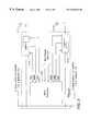
- FIG. 1is a block diagram of an exemplary wireless telephony system integrated with an exemplary broadband distribution network
- FIG. 2is a diagram showing a number of cells positioned to provide overlapping signal coverage using remote transceivers (RADs) spaced closer together to implement the teaching of the present invention
- FIG. 3is a simplified block diagram of a remote transceiver (RAD);
- FIG. 4is a detailed block diagram of that portion of a remote transceiver (RAD) that receives telephony signals from wireless telephones and transmits them via a broadband distribution network to a central transceiver (RASP) and BTS; and
- RADremote transceiver
- RASPcentral transceiver
- BTSBTS
- FIG. 5is a detailed block diagram of that portion of a remote transceiver (RAD) that receives telephony signals via a broadband distribution network from a central transceiver (RASP) and BTS and transmits them to a wireless telephone.
- RADremote transceiver
- RASPcentral transceiver
- circuit elementsare assigned three digit reference numbers.
- the first digit of each reference numberindicates in which figure of the drawing an element is located.
- the second and third digits of each reference numberindicate specific circuit elements. If the same circuit element appears in more than one figure of the drawing, the second and third digits of the reference number for that circuit element remain the same and only the first digit of the reference number changes to indicate the figure of the drawing in which the referenced circuit element is located.
- RAD circuit 319 described with reference to FIG. 3is the same RAD circuit 419 that is described with reference to FIG. 4; and RAD 114 a in FIG. 1 is the same as RAD 214 a in FIG. 2 .
- reverse directionrefers to any signals traveling toward Telephone System 111
- forward directionrefers to any signals traveling toward wireless telephone 115
- downstreamIn the Cable Television industry the “forward direction” is referred to as “downstream”, and the “reverse direction” is referred to as “upstream”. This is mentioned because the wireless telephone system described herein can be utilized with the cable of a cable television distribution network.
- telephony signalsincludes voice, data, facts and any other type of signals that are sent over a telephone network now or the future.
- FIG. 1is shown a simplified block diagram of an exemplary broadband distribution network 110 integrated with elements of a wireless telephone system which includes a plurality of remote transceivers known as Remote Antenna Drivers 114 a-i (RADs), centrally located transceivers known as Remote Antenna Signal Processors 113 (RASP), and a Base Telephone Station 112 (BTS).
- RADsRemote Antenna Drivers 114 a-i
- RASPRemote Antenna Signal Processors 113
- BTSBase Telephone Station 112
- the broadband distribution network 110 disclosed hereinis a conventional hybrid fiber coaxial (HFC) cable to which a plurality of RADs 114 a-i are connected. Electrical power is distributed along broadband distribution network 110 to power line amplifiers (not shown) of the broadband distribution network. This electrical power source, or alternate power sources, are used to provide power to RADs 114 a-i.
- HFChybrid fiber coaxial
- Telephony signals and control signals to be sent between Telephone System 111 and wireless telephones 115are carried via BTS 112 , RASP 113 , broadband network 110 , and RADs 114 a-i.
- Integrated with broadband distribution network 110is a wireless telephony system in which the present invention is utilized.
- One such wireless telephony systemis taught in U.S. patent application Ser. No. 08/695,175, filed Aug. 1, 1996, and entitled “Apparatus And Method For Distributing Wireless Communications Signals To Remote Cellular Antennas”.
- the telephony system disclosed hereinincludes a Base Telephone Station (BTS) 112 which is connected to a telephone system 111 .
- BTS 112is also connected to Remote Antenna Signal Processor (RASP) 113 which is the interface to broadband distribution network 110 . Only one BTS 112 and one RASP 113 are shown in FIG. 1 for simplicity.
- one or more frequency bands or channels of the broadband distribution network 110are reserved to carry telephony signals between telephone system 111 and wireless telephones 115 .
- Telephony signals originating from telephone system 111pass through BTS 112 and are transmitted by RASP 113 , in frequency division multiplexing format, over broadband network 110 to ones of the plurality of RADs 114 a-i which are also connected to broadband distribution network 110 .
- Telephony signals originating at wireless telephones 115are frequency multiplexed together by RADs 114 a-i and transmitted along with control signals via broadband network 110 to an associated RASP 113 , then to BTS 112 , and finally to telephone system 111 .
- BTS 112there are a plurality of transceiver modules (not shown), as is known in the wireless telephony art, each of which operates at a single channel frequency at a time, and which can handle a predetermined maximum number of telephone calls from wireless telephones.
- the frequency that the RADs 114 a-i are assigned to operate atmust correspond to the operating frequency of an assigned BTS 112 transceiver module. If a particular RAD 114 a-i is re-assigned to function with a different transceiver module within BTS 112 , circuit settings within the particular RAD 114 a-i must be changed to function with the different transceiver module.
- transceiver modules in BTS 112are also referred to as channel card modules and radio modules.
- FIG. 1In FIG. 1 are shown three rows of RADs 114 a-i. Typically a number of RADs 114 are spaced along, and connected to, Broadband Distribution Network 110 to provide overlapping signal transmission and reception coverage for the entire wireless telephone system. In accordance with the teaching of the present invention the RADS 114 a-i are physically located close enough so that signals from a wireless telephone 115 operating in the cell covered by, for example, RAD 114 b are also received by adjacent RADs 114 a & c.
- Each RAD 114has two antennas 116 and 117 ; one used to transmit signals to remote wireless telephones 115 , and the other used to receive signals from remote wireless telephones 115 .
- Antenna 117is used to transmit telephony signals to wireless telephones 115
- antenna 116is used to receive telephony signals from wireless telephones 115 .
- RADs 114 a-ecomprise a cluster which all carry (simulcast) communication signals between wireless telephones 115 and a RASP 113 .
- FIG. 2is a diagram showing a number of cells providing overlapping signal coverage provided by RADs 114 a-i that are spaced closer together and each has only one receive ( 216 a-i ) and one transmit ( 217 a-i ) antenna in accordance with the teaching of the present invention.
- the overlapping cellsare designated Cell A through Cell E, for each of which a RAD 214 provides wireless telephony service.
- RAD 214 aprovides service to Cell A
- RAD 214 bprovides service to Cell B
- RAD 214 eproviding service to Cell E.
- Cells A-Eare spaced close enough that, typically, a wireless telephone is operating in more than one cell at a time, and its transmitted signals are received by more than one RAD at a time.
- a wireless telephone 415 located at position Wis within both Cells B and C and its transmitted signals are received by both RADs 214 b & c.
- wireless telephone 415is located at position X, it is within Cells B,C and E and its transmitted signals are received by RADs 214 b,c & e.
- all RADs receiving its signalforward the signal via Broadband Distribution Network 410 to RASP 113 where the signals are processed and combined and forwarded via BTS 112 to telephone system 111 .
- wireless telephone 415moves from position W to position Y through position Z, it is then in the area of coverage of Cells A and B, and it's transmitted signal is received by 20 RADs 214 a & b and forwarded to RASP 113 .
- FIG. 2shows a single cluster of RADs wherein position Z is located, but there may an adjacent cluster of RADs (not shown) whose coverage area overlaps position Z, depending on network layout. Even in that instance the signal is transmitted via Broadband Distribution Network 410 to RASP 113 and via BTS 112 to telephone system 111 .
- FIG. 3is shown a general block diagram of a RAD 314 .
- RAD 314has a first circuit 318 , that is shown in detail in FIG. 5, and that receives telephony signals originating at telephone system 111 and carried via BTS 112 , RASP 113 and broadband distribution network 110 to RAD circuit 318 which transmits the signals via antenna 317 to a remote wireless telephone 115 (not shown).
- RAD circuit 318which transmits the signals via antenna 317 to a remote wireless telephone 115 (not shown).
- There is also a second circuit 319 of RAD 314that is shown in detail in FIG. 4, that receives telephony signals originating at a wireless telephone 115 (not shown) via antenna 316 , and transmits the received signals via broadband distribution network 110 , RASP 113 and BTS 112 to telephone system 111 .
- frequency multiplexed with the telephony signals carried both ways between RASP 113 and a RAD 314are signals for interrogating, reporting, and controlling the various circuitry settings in RAD 314 .
- control signalsThere are different types of control signals that can be sent from RASP 113 to RAD 314 , and each control signal has an address associated therewith that is recognized by only one RAD.
- Microprocessor 320communicates with RAD circuits 318 and 319 via leads AGC, MON, CTRL and other leads to receive and transmit the various signals and to respond thereto as is described in greater detail with reference to FIGS. 4 and 5.
- FIG. 4is shown a detailed block diagram of RAD circuit 419 within a RAD 114 that receives telephony signals from a wireless telephone (not shown), and re-transmits them via broadband distribution network 110 , RASP 113 and BTS 112 to telephone system 111 .
- Telephony signals received from a wireless telephone 115are received by the one receive antenna 416 . As previously described this is normally happening in more than one RAD at a time.
- the received signalsare input to isolator 421 which isolates antenna 416 from other circuitry in RAD circuit 419 .
- the received signalis then input to directional coupler 422 that has a second signal input thereto from gain tone oscillator 423 which is used to implement gain control in RAD circuit 419 .
- the signalis amplified and extraneous signals are filtered from the received telephony signal of interest.
- the amplified and filtered telephony signal and gain control signalare then input to mixer 425 which is the first of two heterodyning stages used to convert the carrier frequency of the telephony signal to the selected carrier frequency used for transmission over broadband distribution network 110 to RASP 113 .
- Mixer 425also has input thereto a signal from local oscillator 426 .
- the frequency of local oscillator 426is digitally controlled and is determined by a binary word applied to its control input CTRL from microprocessor 320 in FIG. 3, responsive to control signals received from RASP 113 (not shown in this Figure).
- a control signal sent from remote RASP 113 to microprocessor 320 in FIG. 2causes microprocessor 320 to send the proper binary word to control input CTRL of local oscillator 426 to set the frequency of the local oscillator.
- the control signal from remote RASP 113causes microprocessor 320 to set the frequency of digitally controlled local oscillator 430 , and other local oscillators in RAD circuit 518 shown in FIG. 5, depending on the carrier frequency chosen to transmit telephony and control signals over broadband distribution network 110 .
- mixer 425results in multiple frequencies being output from the mixer as is known in the art. All these signals are input to narrow pass band SAW filter and amplifier 427 which selects only the difference frequency carrier modulated by the telephony signal and gain control signal created by mixer 425 and amplifies same.
- the signals that pass through SAW filter 427are lower in frequency to be closer to the frequency required for transmitting the telephony signal via broadband distribution network 110 to RASP 113 .
- step attenuator 428which is used to adjust the gain level of the signals in one-half dB steps.
- the amount of attenuation provided by step attenuator 428is controlled by a binary word at its control input AGC from microprocessor 320 (not shown).
- the control of step attenuators 428 and 432is accomplished responsive to control signals received from RASP 113 as part of the gain control operation that controls the signal level of the telephony signals.
- the frequency shifted carrier with telephony signal and gain control signal modulating same that is output from step attenuator 428is input to mixer 429 along with a signal from local oscillator 430 .
- Mixer 429is the second of the aforementioned two heterodyning stages used to convert the telephony signal carrier down to the desired frequency for transmission over an assigned channel of broadband distribution network 110 to RASP 113 .
- the frequency of local oscillator 430is also determined by a binary word applied to its control input CTRL. As described above a control signal is sent from RASP 113 which causes microprocessor 320 to set the frequency of local oscillators 426 and 430 depending on the carrier frequency chosen to transmit the telephony signal over broadband distribution network 110 .
- mixer 429results in multiple frequencies being output from the mixer as is known in the art. All these signals are input to bandpass filter and amplifier 431 which selects only the difference frequency carrier and amplifies same.
- step attenuator 432The filtered and amplified signal output from circuit 431 is input to step attenuator 432 to adjust the gain level of the signal. Similar to the operation of step attenuator 428 , this digitally controlled attenuator is set by control signals at its control input AGC responsive to control signals received from remote RASP 113 as part of the gain control operation.
- control signal oscillator 434includes a local oscillator, the frequency of which is controlled by a binary signal on control leads CTRL from microprocessor 320 to set the frequency of the oscillator.
- RASP 113is the origin from which the control signal is received to set the frequency of control signal oscillator 434 .
- Responsive to different control signals received via RASP 113 microprocessor 320sends signals to control input CTRL of control signal oscillator 434 which cause control signal oscillator 434 to produce an information signal to be sent to RASP 113 .
- the information signalindicates various information about RAD 114 to BTS 113 , including the settings of step attenuators 428 , 432 , 547 , and 549 as part of the gain control operation. This information is used to keep an updated status regarding each of the RADs 114 a-i.
- the output from signal combiner 433now has two signals frequency multiplexed to be returned via broadband network 110 to RASP 113 .
- the signalsare the telephony communication signal received by antenna 416 , and the system information signal output from control signal oscillator 434 .
- These frequency multiplexed signalsare input to band pass filter and amplifier 435 to amplify the signals and to remove any extraneous signals before the signals are coupled via transformer coupler 436 to broadband distribution network 110 to be sent via RASP 113 for signal processing.
- Transformer coupler 436is an impedance matching transformer having 50 ohm primary and 75 ohm secondary windings.
- the secondary winding of transformer 436is wired in series with the center conductor of the video distribution coaxial cable.
- a RAD 114hangs from the coaxial cabling of the broadband distribution network 110 to which it is connected.
- other well known frequency conversion and signal coupling techniquesare used.
- a small portion of the frequency multiplexed signals passing through transformer coupler 436is input to Built In Test (BIT) and power monitor 437 .
- BIT and power monitor 437samples the signal level of the combined signal that is being transmit via broadband distribution network 110 and reports this information to RASP 113 via control signal oscillator 434 which is described above.
- RASP 113detects a drop in received signal level from a RAD 114 , it sends a control signal to the particular RAD 114 which causes the previously described gain control signal from gain control oscillator 423 to be injected and gain control information to be returned to RASP 113 . In this manner RASP 113 can determine where the signal loss is occurring. Thereafter, other control signals can be sent from RASP 113 to a RAD 114 causing changes to the settings of attenuators 428 , 432 , 547 and 549 to adjust the gain level of the RAD.
- BIT and power monitor 437samples the signal level of the combined signal that is being transmit via broadband distribution network 110 and reports this
- FIG. 5is shown a detailed block diagram of RAD circuit 518 that carries telephony signals originating at telephone system 110 and carried via BTS 112 , RASP 113 and broadband distribution network 110 to RAD circuit 518 for transmission to a wireless telephone 115 .
- RAD 114hangs from and is connected to cabling of broadband distribution network 110 .
- Transformer coupler 539is an impedance matching transformer having 75 ohm primary and 50 ohm secondary windings. When broadband distribution network 110 is coaxial cable, the primary winding of transformer 539 is wired in series with the center conductor of the coaxial cable. Transformer 539 is used to connect frequency multiplexed communications and control signals carried on broadband distribution network 110 to the input of all RADs 114 . Only the RADs 114 , the receive frequency which has been tuned by control signals from RASP 113 to the particular frequency of the signals on broadband distribution network 110 actually receive sand forwards the telephony signals to a wireless telephone 115 .
- each RAD 118has a unique address that is used by it to accept only control signals directed specifically to it by RASP 113 .
- the frequency multiplexed telephony and control signals received by RAD circuit 518are input to band pass filter and amplifier 540 .
- This filterpasses all frequency multiplexed telephony communication and control signals that are carried in the assigned channel on broadband distribution network 110 , and excludes all television and other signals carried on broadband distribution network 110 .
- Circuit 540also amplifies these signals.
- the received and amplified signalsare input to mixer 541 along with a signal from local oscillator 542 .
- the frequency of local oscillator 542is digitally controlled at its input CTRL by a signal from microprocessor 320 responsive to control signals microprocessor 320 receives from RASP 113 .
- mixer 541mixes the received signals and the signal from local oscillator 542 and outputs many signals which include the communication and control signals meant for this RAD 114 .
- the frequency of interestis now shifted downward toward the carrier frequency that will be used to transmit communication signals via transmit antenna 517 to wireless telephones 115 .
- the different frequencies output from mixer 541are input to band pass filter and amplifier 543 which is tuned to pass and amplify only the telephony and control signals output from mixer 541 and specifically directed to this RAD 114 .
- mixer 545The selected set of telephony and control signals are now input to mixer 545 of a second heterodyning stage.
- Mixer 545has an input from a local oscillator 546 .
- oscillator 546is digitally controlled by microprocessor 320 responsive to control signals received from RASP 113 and BTS 112 .
- mixer 545combines the signals input to it and provides a number of output signals at different frequencies. All these frequencies are input to an attenuator 547 which is used to adjust the gain level of the signals.
- Attenuator 547is part of the gain control system and is digitally controlled in 1/2 dB steps by control signals at its input CTRL from microprocessor 320 .
- the gain adjusted signal output from attenuator 547is input to SAW filter and amplifier 548 .
- SAW filter 548has a relatively narrow bandpass and passes only the telephony communication signals at the right carrier frequency and amplifies same. Control signals frequency multiplexed with the telephony signal do not pass through SAW filter 548 . Instead, the control signals are input to mixer 544 and are extracted and used as is described further in this specification.
- the telephony communication signals passed through SAW filter 548are further shifted in frequency toward the carrier frequency used for transmitting the telephony signal via transmit antenna 517 to remote wireless telephones 115 (not shown).
- the telephony signalis input to digitally controlled attenuator 549 to adjust the gain level of the signal before it is input to mixer 550 along with the output of digitally controlled local oscillator 551 .
- Attenuator 549is part of the end to end automatic gain control system and is digitally controlled in 2 dB steps. Attenuator 549 is responsive to control signals received from microprocessor 320 at its CTRL input, alike other digitally controlled attenuators in the RAD.
- the amplitude adjusted signal output from attenuator 549is input to the third heterodyning stage which includes mixer 550 and digitally controlled local oscillator 551 .
- the frequency of operation of local oscillator 551is set by a binary control word on its control input CTRL which is received from microprocessor 320 responsive to a control signal received from RASP 113 .
- Mixer 550combines the two signals in a manner well-known in the art to produce several output signals, one of which is the telephony signal having the desired carrier frequency for transmission to a remote wireless telephone 115 .
- the signals output from mixer 550are input to band pass filter and amplifier 552 .
- Band pass filter 552passes only the desired carrier frequency.
- the signalis also amplified before being input to signal splitter 553 .
- the telephony signal input to splitter 553is divided and a portion of the signal goes to BIT (Built In Test) and power monitor 554 , while the remainder of the signal is input to band pass filter and amplifier 555 .
- Bandpass filter 555assures that there are no extraneous signals combined with the desired telephony signal, and amplifies same, before that signal is applied to power amplifier 556 .
- Power amplifier 556amplifies the communication signal and applies it to transmit antenna 517 .
- the signalis transmitted within the area of the cell or sector covered by this RAD 114 , and is received by a remote wireless telephone 115 which is presently communicating with this RAD 114 .
- a portion of the output from power amplifier 556is also input to BIT and power monitor 554 along with the portion from signal splitter 553 .
- the portionsare sampled to determine the signal level of the telephony signal and carrier and reports this information via its output MON to microprocessor 320 .
- Microprocessor 320controls control signal oscillator 434 to report this information back to RASP 113 as previously described with reference to oscillator 434 . This information is used by RASP 113 as part of the automatic gain control operation and testing of the system.
- RASP 113detects a drop in the signal level as reported by bit and power monitor 554 , it sends a control signal to microprocessor 320 to adjust the gain in RAD circuit 518 by re-setting attenuators 547 and 549 .
- a portion of the first intermediate frequency output from bandpass filter and amplifier 543is input to mixer 544 along with the output from binary controlled local oscillator 557 .
- the frequency of operation of local oscillator 557is set by a binary word on its CTRL input from microprocessor 320 responsive to a control signal received from RASP 113 .
- the output of mixer 544is input to reference channel oscillator 558 and forward control channel circuit 559 .
- Circuit 559removes all frequency multiplexed control signals sent from RASP 113 and sends them to microprocessor 320 to be acted upon as described herein with reference to reporting of system operation and settings of attenuators and oscillators.
- Control signalshave a RAD address as part of the control signals and each RAD 114 has a unique address. Therefore, microprocessor 320 in each RAD 114 will only recognize and act upon control signals directed to it.
- microprocessor 320When a RAD 114 receives control signals directed to it, microprocessor 320 responds thereto to perform the action requested by RASP 113 .
- the control signalmay ask for the settings of the local oscillators and attenuators, and this information is returned to RASP 113 using control signal oscillator 434 as previously described.
- the control signal from RASP 113may indicate revised settings for local oscillators and attenuators.
- Microprocessor 320makes the required changes and then sends a confirmation signal back to RASP 113 indicating that the requested changes have been made, again using control signal oscillator 434 .
- a control signal from RASP 113may also request the output levels detected by BIT and power monitors 437 and 554 , and then request that the output from gain tone oscillator 423 be added to the telephony signals. Responsive to any of these control signals, microprocessor 320 performs the requests.
- Reference channel oscillator 558processes the output of mixer 544 to generate a phase lock loop reference signal that is used to provide a master frequency to all local oscillators in RAD circuits 419 and 518 to match their frequency of operation with that of RASP 113 .
Landscapes
- Engineering & Computer Science (AREA)
- Computer Networks & Wireless Communication (AREA)
- Signal Processing (AREA)
- Mobile Radio Communication Systems (AREA)
- Radio Transmission System (AREA)
Abstract
Description
Claims (6)
Priority Applications (6)
| Application Number | Priority Date | Filing Date | Title |
|---|---|---|---|
| US09/092,638US6336042B1 (en) | 1998-06-05 | 1998-06-05 | Reverse link antenna diversity in a wireless telephony system |
| IL13409399AIL134093A0 (en) | 1998-06-05 | 1999-06-04 | Reverse link antenna diversity in a wireless telephony system |
| EP99927221AEP1002382A1 (en) | 1998-06-05 | 1999-06-04 | Reverse link antenna diversity in a wireless telephony system |
| CA002297156ACA2297156A1 (en) | 1998-06-05 | 1999-06-04 | Reverse link antenna diversity in a wireless telephony system |
| AU44181/99AAU4418199A (en) | 1998-06-05 | 1999-06-04 | Reverse link antenna diversity in a wireless telephony system |
| PCT/US1999/012497WO1999063683A1 (en) | 1998-06-05 | 1999-06-04 | Reverse link antenna diversity in a wireless telephony system |
Applications Claiming Priority (1)
| Application Number | Priority Date | Filing Date | Title |
|---|---|---|---|
| US09/092,638US6336042B1 (en) | 1998-06-05 | 1998-06-05 | Reverse link antenna diversity in a wireless telephony system |
Publications (1)
| Publication Number | Publication Date |
|---|---|
| US6336042B1true US6336042B1 (en) | 2002-01-01 |
Family
ID=22234286
Family Applications (1)
| Application Number | Title | Priority Date | Filing Date |
|---|---|---|---|
| US09/092,638Expired - LifetimeUS6336042B1 (en) | 1998-06-05 | 1998-06-05 | Reverse link antenna diversity in a wireless telephony system |
Country Status (6)
| Country | Link |
|---|---|
| US (1) | US6336042B1 (en) |
| EP (1) | EP1002382A1 (en) |
| AU (1) | AU4418199A (en) |
| CA (1) | CA2297156A1 (en) |
| IL (1) | IL134093A0 (en) |
| WO (1) | WO1999063683A1 (en) |
Cited By (71)
| Publication number | Priority date | Publication date | Assignee | Title |
|---|---|---|---|---|
| US20020052179A1 (en)* | 2000-10-28 | 2002-05-02 | Hwang Hee Yong | Circuit for correcting pass band flatness |
| US20020094842A1 (en)* | 2000-12-08 | 2002-07-18 | Ntt Docomo, Inc | Mobile communication system and switching apparatus |
| US20020159118A1 (en)* | 2000-03-21 | 2002-10-31 | Katsuhiko Hiramatsu | Base station apparatus provided with array antennas |
| US20040057393A1 (en)* | 1999-04-21 | 2004-03-25 | Opencell Corporation | Architecture for signal distribution in wireless data networks |
| US20040096222A1 (en)* | 2002-11-15 | 2004-05-20 | Torbjorn Cagenius | Optical fiber coupling configurations for a main-remote radio base station and a hybrid radio base station |
| US20040203339A1 (en)* | 2002-12-03 | 2004-10-14 | Bauman Donald R. | Distributed signal summation and gain control |
| US20050018630A1 (en)* | 1999-04-21 | 2005-01-27 | Opencell Corp. | Architecture for signal distribution in wireless data network |
| US20050018655A1 (en)* | 1999-04-21 | 2005-01-27 | Opencell, Inc. | Architecture for signal and power distribution in wireless data network |
| US6993287B2 (en) | 2003-03-04 | 2006-01-31 | Four Bars Clarity, Llc | Repeater system for strong signal environments |
| US20080200114A1 (en)* | 2005-06-14 | 2008-08-21 | Fraunhofer-Gesellschaft Zur Forderung Der Angewandten Forschung E.V. | Terrestrial Transmitting Station for Transmitting a Terrestrial Broadcast Signal, Satellite-Aided Broadcast System and Receiver for a Satellite-Aided Broadcast System |
| US8175521B2 (en) | 2003-03-04 | 2012-05-08 | Bandwidth Wireless Limited Liability Company | Repeater system for strong signal environments |
| US8532492B2 (en) | 2009-02-03 | 2013-09-10 | Corning Cable Systems Llc | Optical fiber-based distributed antenna systems, components, and related methods for calibration thereof |
| US8639121B2 (en) | 2009-11-13 | 2014-01-28 | Corning Cable Systems Llc | Radio-over-fiber (RoF) system for protocol-independent wired and/or wireless communication |
| US8644844B2 (en) | 2007-12-20 | 2014-02-04 | Corning Mobileaccess Ltd. | Extending outdoor location based services and applications into enclosed areas |
| US8718478B2 (en) | 2007-10-12 | 2014-05-06 | Corning Cable Systems Llc | Hybrid wireless/wired RoF transponder and hybrid RoF communication system using same |
| US8831428B2 (en) | 2010-02-15 | 2014-09-09 | Corning Optical Communications LLC | Dynamic cell bonding (DCB) for radio-over-fiber (RoF)-based networks and communication systems and related methods |
| US8867919B2 (en) | 2007-07-24 | 2014-10-21 | Corning Cable Systems Llc | Multi-port accumulator for radio-over-fiber (RoF) wireless picocellular systems |
| US8873585B2 (en) | 2006-12-19 | 2014-10-28 | Corning Optical Communications Wireless Ltd | Distributed antenna system for MIMO technologies |
| US8983301B2 (en) | 2010-03-31 | 2015-03-17 | Corning Optical Communications LLC | Localization services in optical fiber-based distributed communications components and systems, and related methods |
| US9001811B2 (en) | 2009-05-19 | 2015-04-07 | Adc Telecommunications, Inc. | Method of inserting CDMA beacon pilots in output of distributed remote antenna nodes |
| US9158864B2 (en) | 2012-12-21 | 2015-10-13 | Corning Optical Communications Wireless Ltd | Systems, methods, and devices for documenting a location of installed equipment |
| US9178635B2 (en) | 2014-01-03 | 2015-11-03 | Corning Optical Communications Wireless Ltd | Separation of communication signal sub-bands in distributed antenna systems (DASs) to reduce interference |
| US9185674B2 (en) | 2010-08-09 | 2015-11-10 | Corning Cable Systems Llc | Apparatuses, systems, and methods for determining location of a mobile device(s) in a distributed antenna system(s) |
| US9184843B2 (en) | 2011-04-29 | 2015-11-10 | Corning Optical Communications LLC | Determining propagation delay of communications in distributed antenna systems, and related components, systems, and methods |
| US9240835B2 (en) | 2011-04-29 | 2016-01-19 | Corning Optical Communications LLC | Systems, methods, and devices for increasing radio frequency (RF) power in distributed antenna systems |
| US9247543B2 (en) | 2013-07-23 | 2016-01-26 | Corning Optical Communications Wireless Ltd | Monitoring non-supported wireless spectrum within coverage areas of distributed antenna systems (DASs) |
| US9258052B2 (en) | 2012-03-30 | 2016-02-09 | Corning Optical Communications LLC | Reducing location-dependent interference in distributed antenna systems operating in multiple-input, multiple-output (MIMO) configuration, and related components, systems, and methods |
| US20160079773A1 (en)* | 2013-06-05 | 2016-03-17 | Murata Manufacturing Co., Ltd. | Electronic apparatus and wireless power transmission system |
| US9357551B2 (en) | 2014-05-30 | 2016-05-31 | Corning Optical Communications Wireless Ltd | Systems and methods for simultaneous sampling of serial digital data streams from multiple analog-to-digital converters (ADCS), including in distributed antenna systems |
| US9385810B2 (en) | 2013-09-30 | 2016-07-05 | Corning Optical Communications Wireless Ltd | Connection mapping in distributed communication systems |
| US9419712B2 (en) | 2010-10-13 | 2016-08-16 | Ccs Technology, Inc. | Power management for remote antenna units in distributed antenna systems |
| US9420542B2 (en) | 2014-09-25 | 2016-08-16 | Corning Optical Communications Wireless Ltd | System-wide uplink band gain control in a distributed antenna system (DAS), based on per band gain control of remote uplink paths in remote units |
| US9455784B2 (en) | 2012-10-31 | 2016-09-27 | Corning Optical Communications Wireless Ltd | Deployable wireless infrastructures and methods of deploying wireless infrastructures |
| US9497706B2 (en) | 2013-02-20 | 2016-11-15 | Corning Optical Communications Wireless Ltd | Power management in distributed antenna systems (DASs), and related components, systems, and methods |
| US9509133B2 (en) | 2014-06-27 | 2016-11-29 | Corning Optical Communications Wireless Ltd | Protection of distributed antenna systems |
| US9525472B2 (en) | 2014-07-30 | 2016-12-20 | Corning Incorporated | Reducing location-dependent destructive interference in distributed antenna systems (DASS) operating in multiple-input, multiple-output (MIMO) configuration, and related components, systems, and methods |
| US9531452B2 (en) | 2012-11-29 | 2016-12-27 | Corning Optical Communications LLC | Hybrid intra-cell / inter-cell remote unit antenna bonding in multiple-input, multiple-output (MIMO) distributed antenna systems (DASs) |
| US9577922B2 (en) | 2014-02-18 | 2017-02-21 | Commscope Technologies Llc | Selectively combining uplink signals in distributed antenna systems |
| US9590733B2 (en) | 2009-07-24 | 2017-03-07 | Corning Optical Communications LLC | Location tracking using fiber optic array cables and related systems and methods |
| US9602210B2 (en) | 2014-09-24 | 2017-03-21 | Corning Optical Communications Wireless Ltd | Flexible head-end chassis supporting automatic identification and interconnection of radio interface modules and optical interface modules in an optical fiber-based distributed antenna system (DAS) |
| US9621293B2 (en) | 2012-08-07 | 2017-04-11 | Corning Optical Communications Wireless Ltd | Distribution of time-division multiplexed (TDM) management services in a distributed antenna system, and related components, systems, and methods |
| US9647758B2 (en) | 2012-11-30 | 2017-05-09 | Corning Optical Communications Wireless Ltd | Cabling connectivity monitoring and verification |
| US9648580B1 (en) | 2016-03-23 | 2017-05-09 | Corning Optical Communications Wireless Ltd | Identifying remote units in a wireless distribution system (WDS) based on assigned unique temporal delay patterns |
| US9653861B2 (en) | 2014-09-17 | 2017-05-16 | Corning Optical Communications Wireless Ltd | Interconnection of hardware components |
| US9661781B2 (en) | 2013-07-31 | 2017-05-23 | Corning Optical Communications Wireless Ltd | Remote units for distributed communication systems and related installation methods and apparatuses |
| US9673904B2 (en) | 2009-02-03 | 2017-06-06 | Corning Optical Communications LLC | Optical fiber-based distributed antenna systems, components, and related methods for calibration thereof |
| US9681313B2 (en) | 2015-04-15 | 2017-06-13 | Corning Optical Communications Wireless Ltd | Optimizing remote antenna unit performance using an alternative data channel |
| US9685782B2 (en) | 2010-11-24 | 2017-06-20 | Corning Optical Communications LLC | Power distribution module(s) capable of hot connection and/or disconnection for distributed antenna systems, and related power units, components, and methods |
| US9699723B2 (en) | 2010-10-13 | 2017-07-04 | Ccs Technology, Inc. | Local power management for remote antenna units in distributed antenna systems |
| US9715157B2 (en) | 2013-06-12 | 2017-07-25 | Corning Optical Communications Wireless Ltd | Voltage controlled optical directional coupler |
| US9730228B2 (en) | 2014-08-29 | 2017-08-08 | Corning Optical Communications Wireless Ltd | Individualized gain control of remote uplink band paths in a remote unit in a distributed antenna system (DAS), based on combined uplink power level in the remote unit |
| US9729251B2 (en) | 2012-07-31 | 2017-08-08 | Corning Optical Communications LLC | Cooling system control in distributed antenna systems |
| US9729267B2 (en) | 2014-12-11 | 2017-08-08 | Corning Optical Communications Wireless Ltd | Multiplexing two separate optical links with the same wavelength using asymmetric combining and splitting |
| US9775123B2 (en) | 2014-03-28 | 2017-09-26 | Corning Optical Communications Wireless Ltd. | Individualized gain control of uplink paths in remote units in a distributed antenna system (DAS) based on individual remote unit contribution to combined uplink power |
| US9781553B2 (en) | 2012-04-24 | 2017-10-03 | Corning Optical Communications LLC | Location based services in a distributed communication system, and related components and methods |
| US9785175B2 (en) | 2015-03-27 | 2017-10-10 | Corning Optical Communications Wireless, Ltd. | Combining power from electrically isolated power paths for powering remote units in a distributed antenna system(s) (DASs) |
| US9807700B2 (en) | 2015-02-19 | 2017-10-31 | Corning Optical Communications Wireless Ltd | Offsetting unwanted downlink interference signals in an uplink path in a distributed antenna system (DAS) |
| US9948349B2 (en) | 2015-07-17 | 2018-04-17 | Corning Optical Communications Wireless Ltd | IOT automation and data collection system |
| US9974074B2 (en) | 2013-06-12 | 2018-05-15 | Corning Optical Communications Wireless Ltd | Time-division duplexing (TDD) in distributed communications systems, including distributed antenna systems (DASs) |
| US10128951B2 (en) | 2009-02-03 | 2018-11-13 | Corning Optical Communications LLC | Optical fiber-based distributed antenna systems, components, and related methods for monitoring and configuring thereof |
| US10136200B2 (en) | 2012-04-25 | 2018-11-20 | Corning Optical Communications LLC | Distributed antenna system architectures |
| US10236924B2 (en) | 2016-03-31 | 2019-03-19 | Corning Optical Communications Wireless Ltd | Reducing out-of-channel noise in a wireless distribution system (WDS) |
| US10257056B2 (en) | 2012-11-28 | 2019-04-09 | Corning Optical Communications LLC | Power management for distributed communication systems, and related components, systems, and methods |
| US10455497B2 (en) | 2013-11-26 | 2019-10-22 | Corning Optical Communications LLC | Selective activation of communications services on power-up of a remote unit(s) in a wireless communication system (WCS) based on power consumption |
| US10498434B2 (en) | 2000-07-19 | 2019-12-03 | CommScope Technolgies LLC | Point-to-multipoint digital radio frequency transport |
| US10499269B2 (en) | 2015-11-12 | 2019-12-03 | Commscope Technologies Llc | Systems and methods for assigning controlled nodes to channel interfaces of a controller |
| US10560214B2 (en) | 2015-09-28 | 2020-02-11 | Corning Optical Communications LLC | Downlink and uplink communication path switching in a time-division duplex (TDD) distributed antenna system (DAS) |
| US10785827B2 (en) | 2009-11-12 | 2020-09-22 | Andrew Wireless Systems Gmbh | Master unit, remote unit and multiband transmission system |
| US10992484B2 (en) | 2013-08-28 | 2021-04-27 | Corning Optical Communications LLC | Power management for distributed communication systems, and related components, systems, and methods |
| US11296504B2 (en) | 2010-11-24 | 2022-04-05 | Corning Optical Communications LLC | Power distribution module(s) capable of hot connection and/or disconnection for wireless communication systems, and related power units, components, and methods |
| USRE49377E1 (en) | 2002-12-03 | 2023-01-17 | Commscope Technologies Llc | Distributed digital antenna system |
Families Citing this family (1)
| Publication number | Priority date | Publication date | Assignee | Title |
|---|---|---|---|---|
| AU5148200A (en)* | 1999-05-20 | 2000-12-12 | Transcept, Inc. | Wide band noise reduction system |
Citations (30)
| Publication number | Priority date | Publication date | Assignee | Title |
|---|---|---|---|---|
| US4776032A (en)* | 1985-05-15 | 1988-10-04 | Nippon Telegraph And Telephone Corporation | Repeater for a same frequency with spillover measurement |
| US4882765A (en) | 1987-05-22 | 1989-11-21 | Maxwell Ray F | Data transmission system |
| US5067173A (en) | 1990-12-20 | 1991-11-19 | At&T Bell Laboratories | Microcellular communications system using space diversity reception |
| US5129098A (en) | 1990-09-24 | 1992-07-07 | Novatel Communication Ltd. | Radio telephone using received signal strength in controlling transmission power |
| GB2253770A (en) | 1991-01-15 | 1992-09-16 | Rogers Communications Inc | Multichannel radiotelephony system using bidirectional cable T.V. network |
| US5321736A (en) | 1992-01-03 | 1994-06-14 | Pcs Microcell International Inc. | Distributed RF repeater arrangement for cordless telephones |
| US5381459A (en) | 1991-07-29 | 1995-01-10 | Cable Television Laboratories, Inc. | System for distributing radio telephone signals over a cable television network |
| US5390235A (en)* | 1993-06-23 | 1995-02-14 | Pcs Microcell International, Inc. | Cordless telephone system and switching control method therefor |
| US5396484A (en) | 1991-07-18 | 1995-03-07 | Iwatsu Electric Co., Ltd. | Diversity communication method of time-division, time-compressed multiplexing telephone signal for mobile communication system |
| US5452473A (en) | 1994-02-28 | 1995-09-19 | Qualcomm Incorporated | Reverse link, transmit power correction and limitation in a radiotelephone system |
| US5499241A (en) | 1993-09-17 | 1996-03-12 | Scientific-Atlanta, Inc. | Broadband communications system |
| US5513176A (en) | 1990-12-07 | 1996-04-30 | Qualcomm Incorporated | Dual distributed antenna system |
| US5590173A (en)* | 1992-08-05 | 1996-12-31 | Beasley; Andrew S. | Delay insensitive base station-to-handset interface for radio telephone systems |
| US5781541A (en)* | 1995-05-03 | 1998-07-14 | Bell Atlantic Network Services, Inc. | CDMA system having time-distributed transmission paths for multipath reception |
| US5781859A (en) | 1992-01-03 | 1998-07-14 | Pcs Solutions, Llc | RF repeater arrangement with improved frequency reuse for wireless telephones |
| US5790944A (en)* | 1993-09-28 | 1998-08-04 | Nokia Telecommunications Oy | Measurement of gain error in a base station receiver, and improvement in field strength measurement |
| US5802173A (en) | 1991-01-15 | 1998-09-01 | Rogers Cable Systems Limited | Radiotelephony system |
| US5805983A (en)* | 1996-07-18 | 1998-09-08 | Ericsson Inc. | System and method for equalizing the delay time for transmission paths in a distributed antenna network |
| US5809422A (en)* | 1996-03-08 | 1998-09-15 | Watkins Johnson Company | Distributed microcellular communications system |
| US5809395A (en)* | 1991-01-15 | 1998-09-15 | Rogers Cable Systems Limited | Remote antenna driver for a radio telephony system |
| US5822324A (en)* | 1995-03-16 | 1998-10-13 | Bell Atlantic Network Services, Inc. | Simulcasting digital video programs for broadcast and interactive services |
| US5825762A (en) | 1996-09-24 | 1998-10-20 | Motorola, Inc. | Apparatus and methods for providing wireless communication to a sectorized coverage area |
| US5867763A (en)* | 1996-02-08 | 1999-02-02 | Qualcomm Incorporated | Method and apparatus for integration of a wireless communication system with a cable T.V. system |
| US5918154A (en)* | 1995-08-23 | 1999-06-29 | Pcs Wireless, Inc. | Communications systems employing antenna diversity |
| US5953670A (en)* | 1995-05-02 | 1999-09-14 | Northern Telecom Limited | Arrangement for providing cellular communication via a CATV network |
| US5960353A (en)* | 1996-12-24 | 1999-09-28 | Lucent Technologies, Inc. | Microcell load measurement using feedback control |
| US6023625A (en)* | 1997-02-18 | 2000-02-08 | Ericsson Inc. | System and method for reducing multicast interference in a distributed antenna network |
| US6026284A (en)* | 1996-05-31 | 2000-02-15 | Samsung Electronics Co., Ltd. | Output control unit of mobile communication system and its controlling method |
| US6122529A (en)* | 1998-03-17 | 2000-09-19 | Transcept, Inc. | Simulcast with hierarchical cell structure overlay |
| US6128470A (en)* | 1996-07-18 | 2000-10-03 | Ericsson Inc. | System and method for reducing cumulative noise in a distributed antenna network |
Family Cites Families (1)
| Publication number | Priority date | Publication date | Assignee | Title |
|---|---|---|---|---|
| US5903834A (en)* | 1995-10-06 | 1999-05-11 | Telefonaktiebolaget L/M Ericsson | Distributed indoor digital multiple-access cellular telephone system |
- 1998
- 1998-06-05USUS09/092,638patent/US6336042B1/ennot_activeExpired - Lifetime
- 1999
- 1999-06-04EPEP99927221Apatent/EP1002382A1/ennot_activeWithdrawn
- 1999-06-04CACA002297156Apatent/CA2297156A1/ennot_activeAbandoned
- 1999-06-04WOPCT/US1999/012497patent/WO1999063683A1/ennot_activeApplication Discontinuation
- 1999-06-04ILIL13409399Apatent/IL134093A0/enunknown
- 1999-06-04AUAU44181/99Apatent/AU4418199A/ennot_activeAbandoned
Patent Citations (31)
| Publication number | Priority date | Publication date | Assignee | Title |
|---|---|---|---|---|
| US4776032A (en)* | 1985-05-15 | 1988-10-04 | Nippon Telegraph And Telephone Corporation | Repeater for a same frequency with spillover measurement |
| US4882765A (en) | 1987-05-22 | 1989-11-21 | Maxwell Ray F | Data transmission system |
| US5129098A (en) | 1990-09-24 | 1992-07-07 | Novatel Communication Ltd. | Radio telephone using received signal strength in controlling transmission power |
| US5513176A (en) | 1990-12-07 | 1996-04-30 | Qualcomm Incorporated | Dual distributed antenna system |
| US5067173A (en) | 1990-12-20 | 1991-11-19 | At&T Bell Laboratories | Microcellular communications system using space diversity reception |
| GB2253770A (en) | 1991-01-15 | 1992-09-16 | Rogers Communications Inc | Multichannel radiotelephony system using bidirectional cable T.V. network |
| GB2289198A (en) | 1991-01-15 | 1995-11-08 | Rogers Cantel Inc | Radiotelephony Interface |
| US5809395A (en)* | 1991-01-15 | 1998-09-15 | Rogers Cable Systems Limited | Remote antenna driver for a radio telephony system |
| US5802173A (en) | 1991-01-15 | 1998-09-01 | Rogers Cable Systems Limited | Radiotelephony system |
| US5396484A (en) | 1991-07-18 | 1995-03-07 | Iwatsu Electric Co., Ltd. | Diversity communication method of time-division, time-compressed multiplexing telephone signal for mobile communication system |
| US5381459A (en) | 1991-07-29 | 1995-01-10 | Cable Television Laboratories, Inc. | System for distributing radio telephone signals over a cable television network |
| US5321736A (en) | 1992-01-03 | 1994-06-14 | Pcs Microcell International Inc. | Distributed RF repeater arrangement for cordless telephones |
| US5781859A (en) | 1992-01-03 | 1998-07-14 | Pcs Solutions, Llc | RF repeater arrangement with improved frequency reuse for wireless telephones |
| US5590173A (en)* | 1992-08-05 | 1996-12-31 | Beasley; Andrew S. | Delay insensitive base station-to-handset interface for radio telephone systems |
| US5390235A (en)* | 1993-06-23 | 1995-02-14 | Pcs Microcell International, Inc. | Cordless telephone system and switching control method therefor |
| US5499241A (en) | 1993-09-17 | 1996-03-12 | Scientific-Atlanta, Inc. | Broadband communications system |
| US5790944A (en)* | 1993-09-28 | 1998-08-04 | Nokia Telecommunications Oy | Measurement of gain error in a base station receiver, and improvement in field strength measurement |
| US5452473A (en) | 1994-02-28 | 1995-09-19 | Qualcomm Incorporated | Reverse link, transmit power correction and limitation in a radiotelephone system |
| US5822324A (en)* | 1995-03-16 | 1998-10-13 | Bell Atlantic Network Services, Inc. | Simulcasting digital video programs for broadcast and interactive services |
| US5953670A (en)* | 1995-05-02 | 1999-09-14 | Northern Telecom Limited | Arrangement for providing cellular communication via a CATV network |
| US5781541A (en)* | 1995-05-03 | 1998-07-14 | Bell Atlantic Network Services, Inc. | CDMA system having time-distributed transmission paths for multipath reception |
| US5918154A (en)* | 1995-08-23 | 1999-06-29 | Pcs Wireless, Inc. | Communications systems employing antenna diversity |
| US5867763A (en)* | 1996-02-08 | 1999-02-02 | Qualcomm Incorporated | Method and apparatus for integration of a wireless communication system with a cable T.V. system |
| US5809422A (en)* | 1996-03-08 | 1998-09-15 | Watkins Johnson Company | Distributed microcellular communications system |
| US6026284A (en)* | 1996-05-31 | 2000-02-15 | Samsung Electronics Co., Ltd. | Output control unit of mobile communication system and its controlling method |
| US5805983A (en)* | 1996-07-18 | 1998-09-08 | Ericsson Inc. | System and method for equalizing the delay time for transmission paths in a distributed antenna network |
| US6128470A (en)* | 1996-07-18 | 2000-10-03 | Ericsson Inc. | System and method for reducing cumulative noise in a distributed antenna network |
| US5825762A (en) | 1996-09-24 | 1998-10-20 | Motorola, Inc. | Apparatus and methods for providing wireless communication to a sectorized coverage area |
| US5960353A (en)* | 1996-12-24 | 1999-09-28 | Lucent Technologies, Inc. | Microcell load measurement using feedback control |
| US6023625A (en)* | 1997-02-18 | 2000-02-08 | Ericsson Inc. | System and method for reducing multicast interference in a distributed antenna network |
| US6122529A (en)* | 1998-03-17 | 2000-09-19 | Transcept, Inc. | Simulcast with hierarchical cell structure overlay |
Cited By (149)
| Publication number | Priority date | Publication date | Assignee | Title |
|---|---|---|---|---|
| US20110216751A1 (en)* | 1999-04-21 | 2011-09-08 | Lgc Wireless, Inc. | Architecture for signal and power distribution in wireless data network |
| US7359392B2 (en) | 1999-04-21 | 2008-04-15 | Adc Wireless Solutions, Llc | Architecture for signal distribution in wireless data networks |
| US8824457B2 (en) | 1999-04-21 | 2014-09-02 | Adc Telecommunications, Inc. | Architecture for signal and power distribution in wireless data network |
| US10142813B2 (en) | 1999-04-21 | 2018-11-27 | Commscope Technologies Llc | Architecture for signal and power distribution in wireless data network |
| US20040057393A1 (en)* | 1999-04-21 | 2004-03-25 | Opencell Corporation | Architecture for signal distribution in wireless data networks |
| US9674678B2 (en) | 1999-04-21 | 2017-06-06 | Commscope Technologies Llc | Architecture for signal and power distribution in wireless data network |
| US8379569B2 (en) | 1999-04-21 | 2013-02-19 | Adc Telecommunications, Inc. | Architecture for signal distribution in wireless data network |
| US7969965B2 (en) | 1999-04-21 | 2011-06-28 | Lgc Wireless, Inc. | Architecture for signal and power distribution in wireless data network |
| US20050018630A1 (en)* | 1999-04-21 | 2005-01-27 | Opencell Corp. | Architecture for signal distribution in wireless data network |
| US20050018655A1 (en)* | 1999-04-21 | 2005-01-27 | Opencell, Inc. | Architecture for signal and power distribution in wireless data network |
| US6987989B2 (en)* | 2000-03-21 | 2006-01-17 | Matsushita Electric Industrial Co., Ltd. | Base station apparatus provided with array antennas |
| US20020159118A1 (en)* | 2000-03-21 | 2002-10-31 | Katsuhiko Hiramatsu | Base station apparatus provided with array antennas |
| US10505635B2 (en) | 2000-07-19 | 2019-12-10 | Commscope Technologies Llc | Point-to-multipoint digital radio frequency transport |
| US10498434B2 (en) | 2000-07-19 | 2019-12-03 | CommScope Technolgies LLC | Point-to-multipoint digital radio frequency transport |
| US20020052179A1 (en)* | 2000-10-28 | 2002-05-02 | Hwang Hee Yong | Circuit for correcting pass band flatness |
| US6678511B2 (en)* | 2000-10-28 | 2004-01-13 | Amotech Co., Ltd. | Circuit for correcting pass band flatness |
| US20020094842A1 (en)* | 2000-12-08 | 2002-07-18 | Ntt Docomo, Inc | Mobile communication system and switching apparatus |
| US7003321B2 (en)* | 2000-12-08 | 2006-02-21 | Ntt Docomo, Inc. | Mobile communication system and switching apparatus |
| WO2004047472A1 (en)* | 2002-11-15 | 2004-06-03 | Telefonaktiebolaget Lm Ericsson (Publ) | Optical fiber coupling configurations for a main-remote radio base station and a hybrid radio base station |
| US7047028B2 (en) | 2002-11-15 | 2006-05-16 | Telefonaktiebolaget Lm Ericsson (Publ) | Optical fiber coupling configurations for a main-remote radio base station and a hybrid radio base station |
| KR101036022B1 (en) | 2002-11-15 | 2011-05-19 | 텔레폰악티에볼라겟엘엠에릭슨(펍) | Fiber-Coupled Configuration for Main-Remote and Hybrid Wireless Base Stations |
| US20040096222A1 (en)* | 2002-11-15 | 2004-05-20 | Torbjorn Cagenius | Optical fiber coupling configurations for a main-remote radio base station and a hybrid radio base station |
| CN1310541C (en)* | 2002-11-15 | 2007-04-11 | 艾利森电话股份有限公司 | Optical fiber coupling configurations for a main-remote radio base station and a hybrid radio base station |
| USRE50112E1 (en) | 2002-12-03 | 2024-09-03 | Outdoor Wireless Networks LLC | Distributed digital antenna system |
| USRE49377E1 (en) | 2002-12-03 | 2023-01-17 | Commscope Technologies Llc | Distributed digital antenna system |
| US7171244B2 (en)* | 2002-12-03 | 2007-01-30 | Adc Telecommunications, Inc. | Communication system and method with gain control for signals from distributed antennas |
| US7917177B2 (en)* | 2002-12-03 | 2011-03-29 | Adc Telecommunications, Inc. | Communication system and method with gain control for signals from distributed antennas |
| US20070117592A1 (en)* | 2002-12-03 | 2007-05-24 | Adc Telecommunications, Inc. | Communication system and method with gain control for signals from distributed antennas |
| US20090238573A1 (en)* | 2002-12-03 | 2009-09-24 | Adc Telecommunications, Inc. | Communication system and method with gain control for signals from distributed antennas |
| US7546138B2 (en) | 2002-12-03 | 2009-06-09 | Adc Telecommunications, Inc. | Communication system and method with gain control for signals from distributed antennas |
| US20040203339A1 (en)* | 2002-12-03 | 2004-10-14 | Bauman Donald R. | Distributed signal summation and gain control |
| US8175521B2 (en) | 2003-03-04 | 2012-05-08 | Bandwidth Wireless Limited Liability Company | Repeater system for strong signal environments |
| US8346158B2 (en) | 2003-03-04 | 2013-01-01 | Bandwidth Wireless Limited Liability Company | Repeater system for strong signal environments |
| US6993287B2 (en) | 2003-03-04 | 2006-01-31 | Four Bars Clarity, Llc | Repeater system for strong signal environments |
| US20080200114A1 (en)* | 2005-06-14 | 2008-08-21 | Fraunhofer-Gesellschaft Zur Forderung Der Angewandten Forschung E.V. | Terrestrial Transmitting Station for Transmitting a Terrestrial Broadcast Signal, Satellite-Aided Broadcast System and Receiver for a Satellite-Aided Broadcast System |
| US8369774B2 (en)* | 2005-06-14 | 2013-02-05 | Fraunhofer-Gesellschaft Zur Foerderung Der Angewandten Forschung E.V. | Terrestrial transmitting station for transmitting a terrestrial broadcast signal, satellite-aided broadcast system and receiver for a satellite-aided broadcast system |
| US8873585B2 (en) | 2006-12-19 | 2014-10-28 | Corning Optical Communications Wireless Ltd | Distributed antenna system for MIMO technologies |
| US9130613B2 (en) | 2006-12-19 | 2015-09-08 | Corning Optical Communications Wireless Ltd | Distributed antenna system for MIMO technologies |
| US8867919B2 (en) | 2007-07-24 | 2014-10-21 | Corning Cable Systems Llc | Multi-port accumulator for radio-over-fiber (RoF) wireless picocellular systems |
| US8718478B2 (en) | 2007-10-12 | 2014-05-06 | Corning Cable Systems Llc | Hybrid wireless/wired RoF transponder and hybrid RoF communication system using same |
| US8644844B2 (en) | 2007-12-20 | 2014-02-04 | Corning Mobileaccess Ltd. | Extending outdoor location based services and applications into enclosed areas |
| US10153841B2 (en) | 2009-02-03 | 2018-12-11 | Corning Optical Communications LLC | Optical fiber-based distributed antenna systems, components, and related methods for calibration thereof |
| US8532492B2 (en) | 2009-02-03 | 2013-09-10 | Corning Cable Systems Llc | Optical fiber-based distributed antenna systems, components, and related methods for calibration thereof |
| US9112611B2 (en) | 2009-02-03 | 2015-08-18 | Corning Optical Communications LLC | Optical fiber-based distributed antenna systems, components, and related methods for calibration thereof |
| US9673904B2 (en) | 2009-02-03 | 2017-06-06 | Corning Optical Communications LLC | Optical fiber-based distributed antenna systems, components, and related methods for calibration thereof |
| US9900097B2 (en) | 2009-02-03 | 2018-02-20 | Corning Optical Communications LLC | Optical fiber-based distributed antenna systems, components, and related methods for calibration thereof |
| US10128951B2 (en) | 2009-02-03 | 2018-11-13 | Corning Optical Communications LLC | Optical fiber-based distributed antenna systems, components, and related methods for monitoring and configuring thereof |
| US9001811B2 (en) | 2009-05-19 | 2015-04-07 | Adc Telecommunications, Inc. | Method of inserting CDMA beacon pilots in output of distributed remote antenna nodes |
| US10070258B2 (en) | 2009-07-24 | 2018-09-04 | Corning Optical Communications LLC | Location tracking using fiber optic array cables and related systems and methods |
| US9590733B2 (en) | 2009-07-24 | 2017-03-07 | Corning Optical Communications LLC | Location tracking using fiber optic array cables and related systems and methods |
| US10785827B2 (en) | 2009-11-12 | 2020-09-22 | Andrew Wireless Systems Gmbh | Master unit, remote unit and multiband transmission system |
| US9219879B2 (en) | 2009-11-13 | 2015-12-22 | Corning Optical Communications LLC | Radio-over-fiber (ROF) system for protocol-independent wired and/or wireless communication |
| US8639121B2 (en) | 2009-11-13 | 2014-01-28 | Corning Cable Systems Llc | Radio-over-fiber (RoF) system for protocol-independent wired and/or wireless communication |
| US9729238B2 (en) | 2009-11-13 | 2017-08-08 | Corning Optical Communications LLC | Radio-over-fiber (ROF) system for protocol-independent wired and/or wireless communication |
| US9485022B2 (en) | 2009-11-13 | 2016-11-01 | Corning Optical Communications LLC | Radio-over-fiber (ROF) system for protocol-independent wired and/or wireless communication |
| US9319138B2 (en) | 2010-02-15 | 2016-04-19 | Corning Optical Communications LLC | Dynamic cell bonding (DCB) for radio-over-fiber (RoF)-based networks and communication systems and related methods |
| US8831428B2 (en) | 2010-02-15 | 2014-09-09 | Corning Optical Communications LLC | Dynamic cell bonding (DCB) for radio-over-fiber (RoF)-based networks and communication systems and related methods |
| US9967032B2 (en) | 2010-03-31 | 2018-05-08 | Corning Optical Communications LLC | Localization services in optical fiber-based distributed communications components and systems, and related methods |
| US8983301B2 (en) | 2010-03-31 | 2015-03-17 | Corning Optical Communications LLC | Localization services in optical fiber-based distributed communications components and systems, and related methods |
| US10448205B2 (en) | 2010-08-09 | 2019-10-15 | Corning Optical Communications LLC | Apparatuses, systems, and methods for determining location of a mobile device(s) in a distributed antenna system(s) |
| US9913094B2 (en) | 2010-08-09 | 2018-03-06 | Corning Optical Communications LLC | Apparatuses, systems, and methods for determining location of a mobile device(s) in a distributed antenna system(s) |
| US12160789B2 (en) | 2010-08-09 | 2024-12-03 | Corning Optical Communications LLC | Apparatuses, systems, and methods for determining location of a mobile device(s) in a distributed antenna system(s) |
| US9185674B2 (en) | 2010-08-09 | 2015-11-10 | Corning Cable Systems Llc | Apparatuses, systems, and methods for determining location of a mobile device(s) in a distributed antenna system(s) |
| US10959047B2 (en) | 2010-08-09 | 2021-03-23 | Corning Optical Communications LLC | Apparatuses, systems, and methods for determining location of a mobile device(s) in a distributed antenna system(s) |
| US11653175B2 (en) | 2010-08-09 | 2023-05-16 | Corning Optical Communications LLC | Apparatuses, systems, and methods for determining location of a mobile device(s) in a distributed antenna system(s) |
| US11178609B2 (en) | 2010-10-13 | 2021-11-16 | Corning Optical Communications LLC | Power management for remote antenna units in distributed antenna systems |
| US11212745B2 (en) | 2010-10-13 | 2021-12-28 | Corning Optical Communications LLC | Power management for remote antenna units in distributed antenna systems |
| US10045288B2 (en) | 2010-10-13 | 2018-08-07 | Corning Optical Communications LLC | Power management for remote antenna units in distributed antenna systems |
| US11224014B2 (en) | 2010-10-13 | 2022-01-11 | Corning Optical Communications LLC | Power management for remote antenna units in distributed antenna systems |
| US10420025B2 (en) | 2010-10-13 | 2019-09-17 | Corning Optical Communications LLC | Local power management for remote antenna units in distributed antenna systems |
| US10104610B2 (en) | 2010-10-13 | 2018-10-16 | Corning Optical Communications LLC | Local power management for remote antenna units in distributed antenna systems |
| US11671914B2 (en) | 2010-10-13 | 2023-06-06 | Corning Optical Communications LLC | Power management for remote antenna units in distributed antenna systems |
| US9419712B2 (en) | 2010-10-13 | 2016-08-16 | Ccs Technology, Inc. | Power management for remote antenna units in distributed antenna systems |
| US10425891B2 (en) | 2010-10-13 | 2019-09-24 | Corning Optical Communications LLC | Power management for remote antenna units in distributed antenna systems |
| US9699723B2 (en) | 2010-10-13 | 2017-07-04 | Ccs Technology, Inc. | Local power management for remote antenna units in distributed antenna systems |
| US9685782B2 (en) | 2010-11-24 | 2017-06-20 | Corning Optical Communications LLC | Power distribution module(s) capable of hot connection and/or disconnection for distributed antenna systems, and related power units, components, and methods |
| US11715949B2 (en) | 2010-11-24 | 2023-08-01 | Corning Optical Communications LLC | Power distribution module(s) capable of hot connection and/or disconnection for wireless communication systems, and related power units, components, and methods |
| US10454270B2 (en) | 2010-11-24 | 2019-10-22 | Corning Optical Communicatons LLC | Power distribution module(s) capable of hot connection and/or disconnection for wireless communication systems, and related power units, components, and methods |
| US11296504B2 (en) | 2010-11-24 | 2022-04-05 | Corning Optical Communications LLC | Power distribution module(s) capable of hot connection and/or disconnection for wireless communication systems, and related power units, components, and methods |
| US11114852B2 (en) | 2010-11-24 | 2021-09-07 | Corning Optical Communications LLC | Power distribution module(s) capable of hot connection and/or disconnection for wireless communication systems, and related power units, components, and methods |
| US9369222B2 (en) | 2011-04-29 | 2016-06-14 | Corning Optical Communications LLC | Determining propagation delay of communications in distributed antenna systems, and related components, systems, and methods |
| US10148347B2 (en) | 2011-04-29 | 2018-12-04 | Corning Optical Communications LLC | Systems, methods, and devices for increasing radio frequency (RF) power in distributed antenna systems |
| US9807722B2 (en) | 2011-04-29 | 2017-10-31 | Corning Optical Communications LLC | Determining propagation delay of communications in distributed antenna systems, and related components, systems, and methods |
| US9806797B2 (en) | 2011-04-29 | 2017-10-31 | Corning Optical Communications LLC | Systems, methods, and devices for increasing radio frequency (RF) power in distributed antenna systems |
| US9184843B2 (en) | 2011-04-29 | 2015-11-10 | Corning Optical Communications LLC | Determining propagation delay of communications in distributed antenna systems, and related components, systems, and methods |
| US9240835B2 (en) | 2011-04-29 | 2016-01-19 | Corning Optical Communications LLC | Systems, methods, and devices for increasing radio frequency (RF) power in distributed antenna systems |
| US9258052B2 (en) | 2012-03-30 | 2016-02-09 | Corning Optical Communications LLC | Reducing location-dependent interference in distributed antenna systems operating in multiple-input, multiple-output (MIMO) configuration, and related components, systems, and methods |
| US9813127B2 (en) | 2012-03-30 | 2017-11-07 | Corning Optical Communications LLC | Reducing location-dependent interference in distributed antenna systems operating in multiple-input, multiple-output (MIMO) configuration, and related components, systems, and methods |
| US9781553B2 (en) | 2012-04-24 | 2017-10-03 | Corning Optical Communications LLC | Location based services in a distributed communication system, and related components and methods |
| US10136200B2 (en) | 2012-04-25 | 2018-11-20 | Corning Optical Communications LLC | Distributed antenna system architectures |
| US10349156B2 (en) | 2012-04-25 | 2019-07-09 | Corning Optical Communications LLC | Distributed antenna system architectures |
| US9729251B2 (en) | 2012-07-31 | 2017-08-08 | Corning Optical Communications LLC | Cooling system control in distributed antenna systems |
| US9621293B2 (en) | 2012-08-07 | 2017-04-11 | Corning Optical Communications Wireless Ltd | Distribution of time-division multiplexed (TDM) management services in a distributed antenna system, and related components, systems, and methods |
| US9973968B2 (en) | 2012-08-07 | 2018-05-15 | Corning Optical Communications Wireless Ltd | Distribution of time-division multiplexed (TDM) management services in a distributed antenna system, and related components, systems, and methods |
| US9455784B2 (en) | 2012-10-31 | 2016-09-27 | Corning Optical Communications Wireless Ltd | Deployable wireless infrastructures and methods of deploying wireless infrastructures |
| US10257056B2 (en) | 2012-11-28 | 2019-04-09 | Corning Optical Communications LLC | Power management for distributed communication systems, and related components, systems, and methods |
| US11665069B2 (en) | 2012-11-28 | 2023-05-30 | Corning Optical Communications LLC | Power management for distributed communication systems, and related components, systems, and methods |
| US10999166B2 (en) | 2012-11-28 | 2021-05-04 | Corning Optical Communications LLC | Power management for distributed communication systems, and related components, systems, and methods |
| US10530670B2 (en) | 2012-11-28 | 2020-01-07 | Corning Optical Communications LLC | Power management for distributed communication systems, and related components, systems, and methods |
| US9531452B2 (en) | 2012-11-29 | 2016-12-27 | Corning Optical Communications LLC | Hybrid intra-cell / inter-cell remote unit antenna bonding in multiple-input, multiple-output (MIMO) distributed antenna systems (DASs) |
| US10361782B2 (en) | 2012-11-30 | 2019-07-23 | Corning Optical Communications LLC | Cabling connectivity monitoring and verification |
| US9647758B2 (en) | 2012-11-30 | 2017-05-09 | Corning Optical Communications Wireless Ltd | Cabling connectivity monitoring and verification |
| US9158864B2 (en) | 2012-12-21 | 2015-10-13 | Corning Optical Communications Wireless Ltd | Systems, methods, and devices for documenting a location of installed equipment |
| US9414192B2 (en) | 2012-12-21 | 2016-08-09 | Corning Optical Communications Wireless Ltd | Systems, methods, and devices for documenting a location of installed equipment |
| US9497706B2 (en) | 2013-02-20 | 2016-11-15 | Corning Optical Communications Wireless Ltd | Power management in distributed antenna systems (DASs), and related components, systems, and methods |
| US9866042B2 (en)* | 2013-06-05 | 2018-01-09 | Murata Manufacturing Co., Ltd. | Electronic apparatus and wireless power transmission system |
| US20160079773A1 (en)* | 2013-06-05 | 2016-03-17 | Murata Manufacturing Co., Ltd. | Electronic apparatus and wireless power transmission system |
| US11291001B2 (en) | 2013-06-12 | 2022-03-29 | Corning Optical Communications LLC | Time-division duplexing (TDD) in distributed communications systems, including distributed antenna systems (DASs) |
| US9974074B2 (en) | 2013-06-12 | 2018-05-15 | Corning Optical Communications Wireless Ltd | Time-division duplexing (TDD) in distributed communications systems, including distributed antenna systems (DASs) |
| US9715157B2 (en) | 2013-06-12 | 2017-07-25 | Corning Optical Communications Wireless Ltd | Voltage controlled optical directional coupler |
| US11792776B2 (en) | 2013-06-12 | 2023-10-17 | Corning Optical Communications LLC | Time-division duplexing (TDD) in distributed communications systems, including distributed antenna systems (DASs) |
| US9526020B2 (en) | 2013-07-23 | 2016-12-20 | Corning Optical Communications Wireless Ltd | Monitoring non-supported wireless spectrum within coverage areas of distributed antenna systems (DASs) |
| US10292056B2 (en) | 2013-07-23 | 2019-05-14 | Corning Optical Communications LLC | Monitoring non-supported wireless spectrum within coverage areas of distributed antenna systems (DASs) |
| US9247543B2 (en) | 2013-07-23 | 2016-01-26 | Corning Optical Communications Wireless Ltd | Monitoring non-supported wireless spectrum within coverage areas of distributed antenna systems (DASs) |
| US9967754B2 (en) | 2013-07-23 | 2018-05-08 | Corning Optical Communications Wireless Ltd | Monitoring non-supported wireless spectrum within coverage areas of distributed antenna systems (DASs) |
| US9661781B2 (en) | 2013-07-31 | 2017-05-23 | Corning Optical Communications Wireless Ltd | Remote units for distributed communication systems and related installation methods and apparatuses |
| US10992484B2 (en) | 2013-08-28 | 2021-04-27 | Corning Optical Communications LLC | Power management for distributed communication systems, and related components, systems, and methods |
| US11516030B2 (en) | 2013-08-28 | 2022-11-29 | Corning Optical Communications LLC | Power management for distributed communication systems, and related components, systems, and methods |
| US9385810B2 (en) | 2013-09-30 | 2016-07-05 | Corning Optical Communications Wireless Ltd | Connection mapping in distributed communication systems |
| US10455497B2 (en) | 2013-11-26 | 2019-10-22 | Corning Optical Communications LLC | Selective activation of communications services on power-up of a remote unit(s) in a wireless communication system (WCS) based on power consumption |
| US9178635B2 (en) | 2014-01-03 | 2015-11-03 | Corning Optical Communications Wireless Ltd | Separation of communication signal sub-bands in distributed antenna systems (DASs) to reduce interference |
| US10291295B2 (en) | 2014-02-18 | 2019-05-14 | Commscope Technologies Llc | Selectively combining uplink signals in distributed antenna systems |
| US9577922B2 (en) | 2014-02-18 | 2017-02-21 | Commscope Technologies Llc | Selectively combining uplink signals in distributed antenna systems |
| US9775123B2 (en) | 2014-03-28 | 2017-09-26 | Corning Optical Communications Wireless Ltd. | Individualized gain control of uplink paths in remote units in a distributed antenna system (DAS) based on individual remote unit contribution to combined uplink power |
| US9357551B2 (en) | 2014-05-30 | 2016-05-31 | Corning Optical Communications Wireless Ltd | Systems and methods for simultaneous sampling of serial digital data streams from multiple analog-to-digital converters (ADCS), including in distributed antenna systems |
| US9807772B2 (en) | 2014-05-30 | 2017-10-31 | Corning Optical Communications Wireless Ltd. | Systems and methods for simultaneous sampling of serial digital data streams from multiple analog-to-digital converters (ADCs), including in distributed antenna systems |
| US9509133B2 (en) | 2014-06-27 | 2016-11-29 | Corning Optical Communications Wireless Ltd | Protection of distributed antenna systems |
| US10256879B2 (en) | 2014-07-30 | 2019-04-09 | Corning Incorporated | Reducing location-dependent destructive interference in distributed antenna systems (DASS) operating in multiple-input, multiple-output (MIMO) configuration, and related components, systems, and methods |
| US9525472B2 (en) | 2014-07-30 | 2016-12-20 | Corning Incorporated | Reducing location-dependent destructive interference in distributed antenna systems (DASS) operating in multiple-input, multiple-output (MIMO) configuration, and related components, systems, and methods |
| US9929786B2 (en) | 2014-07-30 | 2018-03-27 | Corning Incorporated | Reducing location-dependent destructive interference in distributed antenna systems (DASS) operating in multiple-input, multiple-output (MIMO) configuration, and related components, systems, and methods |
| US9730228B2 (en) | 2014-08-29 | 2017-08-08 | Corning Optical Communications Wireless Ltd | Individualized gain control of remote uplink band paths in a remote unit in a distributed antenna system (DAS), based on combined uplink power level in the remote unit |
| US10397929B2 (en) | 2014-08-29 | 2019-08-27 | Corning Optical Communications LLC | Individualized gain control of remote uplink band paths in a remote unit in a distributed antenna system (DAS), based on combined uplink power level in the remote unit |
| US9653861B2 (en) | 2014-09-17 | 2017-05-16 | Corning Optical Communications Wireless Ltd | Interconnection of hardware components |
| US9602210B2 (en) | 2014-09-24 | 2017-03-21 | Corning Optical Communications Wireless Ltd | Flexible head-end chassis supporting automatic identification and interconnection of radio interface modules and optical interface modules in an optical fiber-based distributed antenna system (DAS) |
| US9929810B2 (en) | 2014-09-24 | 2018-03-27 | Corning Optical Communications Wireless Ltd | Flexible head-end chassis supporting automatic identification and interconnection of radio interface modules and optical interface modules in an optical fiber-based distributed antenna system (DAS) |
| US9788279B2 (en) | 2014-09-25 | 2017-10-10 | Corning Optical Communications Wireless Ltd | System-wide uplink band gain control in a distributed antenna system (DAS), based on per-band gain control of remote uplink paths in remote units |
| US9420542B2 (en) | 2014-09-25 | 2016-08-16 | Corning Optical Communications Wireless Ltd | System-wide uplink band gain control in a distributed antenna system (DAS), based on per band gain control of remote uplink paths in remote units |
| US9729267B2 (en) | 2014-12-11 | 2017-08-08 | Corning Optical Communications Wireless Ltd | Multiplexing two separate optical links with the same wavelength using asymmetric combining and splitting |
| US10135561B2 (en) | 2014-12-11 | 2018-11-20 | Corning Optical Communications Wireless Ltd | Multiplexing two separate optical links with the same wavelength using asymmetric combining and splitting |
| US10292114B2 (en) | 2015-02-19 | 2019-05-14 | Corning Optical Communications LLC | Offsetting unwanted downlink interference signals in an uplink path in a distributed antenna system (DAS) |
| US9807700B2 (en) | 2015-02-19 | 2017-10-31 | Corning Optical Communications Wireless Ltd | Offsetting unwanted downlink interference signals in an uplink path in a distributed antenna system (DAS) |
| US9785175B2 (en) | 2015-03-27 | 2017-10-10 | Corning Optical Communications Wireless, Ltd. | Combining power from electrically isolated power paths for powering remote units in a distributed antenna system(s) (DASs) |
| US9681313B2 (en) | 2015-04-15 | 2017-06-13 | Corning Optical Communications Wireless Ltd | Optimizing remote antenna unit performance using an alternative data channel |
| US10009094B2 (en) | 2015-04-15 | 2018-06-26 | Corning Optical Communications Wireless Ltd | Optimizing remote antenna unit performance using an alternative data channel |
| US9948349B2 (en) | 2015-07-17 | 2018-04-17 | Corning Optical Communications Wireless Ltd | IOT automation and data collection system |
| US10560214B2 (en) | 2015-09-28 | 2020-02-11 | Corning Optical Communications LLC | Downlink and uplink communication path switching in a time-division duplex (TDD) distributed antenna system (DAS) |
| US10499269B2 (en) | 2015-11-12 | 2019-12-03 | Commscope Technologies Llc | Systems and methods for assigning controlled nodes to channel interfaces of a controller |
| US9648580B1 (en) | 2016-03-23 | 2017-05-09 | Corning Optical Communications Wireless Ltd | Identifying remote units in a wireless distribution system (WDS) based on assigned unique temporal delay patterns |
| US10236924B2 (en) | 2016-03-31 | 2019-03-19 | Corning Optical Communications Wireless Ltd | Reducing out-of-channel noise in a wireless distribution system (WDS) |
Also Published As
| Publication number | Publication date |
|---|---|
| AU4418199A (en) | 1999-12-20 |
| WO1999063683A1 (en) | 1999-12-09 |
| IL134093A0 (en) | 2001-04-30 |
| EP1002382A1 (en) | 2000-05-24 |
| CA2297156A1 (en) | 1999-12-09 |
| WO1999063683A8 (en) | 2001-02-01 |
Similar Documents
| Publication | Publication Date | Title |
|---|---|---|
| US6336042B1 (en) | Reverse link antenna diversity in a wireless telephony system | |
| US6374124B1 (en) | Dynamic reallocation of transceivers used to interconnect wireless telephones to a broadband network | |
| US6223021B1 (en) | Signal filtering in a transceiver for a wireless telephone system | |
| US6192216B1 (en) | Remotely controlled gain control of transceiver used to inter-connect wireless telephones to a broadband network | |
| US6122529A (en) | Simulcast with hierarchical cell structure overlay | |
| EP0442259B1 (en) | Regenerative RF bi-directional amplifier system | |
| US6349200B1 (en) | Monitoring and command system for transceivers used to inter-connect wireless telephones to a broadband network | |
| US6337754B1 (en) | Optical conversion relay amplification system | |
| US5187806A (en) | Apparatus and method for expanding cellular system capacity | |
| US6047199A (en) | Systems and methods for transmitting mobile radio signals | |
| EP1037411A2 (en) | Gain equalization for optical fiber distribution network | |
| EP0476569A2 (en) | Mobile communication system | |
| EP0468688B1 (en) | Method and apparatus for providing wireless communications between remote locations | |
| US7085530B2 (en) | Dynamic capacity allocation of in-building system | |
| CN1145706A (en) | Cellular radio systems, repeaters and base stations | |
| US6513163B1 (en) | Embedded forward reference and control | |
| US20030003917A1 (en) | Wireless communication system, apparatus and method for providing wireless communication within a building structure | |
| US6438359B1 (en) | Dual transmitter arrangement with back-up switching | |
| JPH10117150A (en) | Method and arrangement relating to signal transmission | |
| US11368221B2 (en) | Multi-range communication system | |
| AU727274B2 (en) | Method of combining several signals, and base station | |
| US5867792A (en) | Radio communication system | |
| EP0909486A2 (en) | Base station with antenna, including an amplifier, located at a distance from the base station | |
| US6741839B1 (en) | System and method for monitoring adjacent channel power in a wireless base station | |
| JPH09139705A (en) | Radio repeater |
Legal Events
| Date | Code | Title | Description |
|---|---|---|---|
| AS | Assignment | Owner name:LOCKHEED MARTIN CORPORATION, NEW HAMPSHIRE Free format text:ASSIGNMENT OF ASSIGNORS INTEREST;ASSIGNORS:DAWSON, MICHAEL T.;JOHNSON, THOMAS J.;BIANCHI, CHARLES H.;REEL/FRAME:009228/0161 Effective date:19980602 | |
| AS | Assignment | Owner name:TRANSCEPT, INC., NEW HAMPSHIRE Free format text:ASSIGNMENT OF ASSIGNORS INTEREST;ASSIGNOR:LOCKHEED MARTIN CORPORATION;REEL/FRAME:010144/0399 Effective date:19990719 | |
| STCF | Information on status: patent grant | Free format text:PATENTED CASE | |
| AS | Assignment | Owner name:CROWN CASTLE TRANS OC CORP., TEXAS Free format text:ASSIGNMENT OF ASSIGNORS INTEREST;ASSIGNOR:TRANSCEPT, INC.;REEL/FRAME:013288/0344 Effective date:20020831 | |
| AS | Assignment | Owner name:CROWN CASTLE TRANS OC CORP., TEXAS Free format text:ASSIGNMENT OF ASSIGNORS INTEREST;ASSIGNOR:TRANSCEPT, INC.;REEL/FRAME:014090/0759 Effective date:20020828 Owner name:OPENCELL CORP., NEW HAMPSHIRE Free format text:CHANGE OF NAME;ASSIGNOR:CROWN CASTLE TRANS OC CORP.;REEL/FRAME:014090/0764 Effective date:20020813 | |
| AS | Assignment | Owner name:CROWN CASTLE TRANS OC CORP., NEW HAMPSHIRE Free format text:ASSIGNMENT OF ASSIGNORS INTEREST;ASSIGNOR:TRANSCEPT, INC.;REEL/FRAME:014128/0324 Effective date:20020828 Owner name:OPENCELL CORP., NEW HAMPSHIRE Free format text:CHANGE OF NAME;ASSIGNOR:CROWN CASTLE TRANS OC CORP.;REEL/FRAME:014128/0166 Effective date:20020830 | |
| FEPP | Fee payment procedure | Free format text:PAT HOLDER NO LONGER CLAIMS SMALL ENTITY STATUS, ENTITY STATUS SET TO UNDISCOUNTED (ORIGINAL EVENT CODE: STOL); ENTITY STATUS OF PATENT OWNER: LARGE ENTITY | |
| FPAY | Fee payment | Year of fee payment:4 | |
| AS | Assignment | Owner name:ADC WIRELESS SOLUTIONS LLC, MINNESOTA Free format text:ASSIGNMENT OF ASSIGNORS INTEREST;ASSIGNOR:OPENCELL CORPORATION;REEL/FRAME:017136/0752 Effective date:20051222 | |
| FPAY | Fee payment | Year of fee payment:8 | |
| AS | Assignment | Owner name:LGC WIRELESS, INC., CALIFORNIA Free format text:MERGER;ASSIGNOR:ADC WIRELESS SOLUTIONS LLC;REEL/FRAME:025440/0889 Effective date:20090925 | |
| AS | Assignment | Owner name:LGC WIRELESS, LLC, CALIFORNIA Free format text:CHANGE OF NAME;ASSIGNOR:LGC WIRELESS, INC.;REEL/FRAME:028756/0251 Effective date:20101208 Owner name:ADC TELECOMMUNICATIONS, INC., MINNESOTA Free format text:MERGER;ASSIGNOR:LGC WIRELESS, LLC;REEL/FRAME:028756/0734 Effective date:20110926 | |
| FPAY | Fee payment | Year of fee payment:12 | |
| AS | Assignment | Owner name:TYCO ELECTRONICS SERVICES GMBH, SWITZERLAND Free format text:ASSIGNMENT OF ASSIGNORS INTEREST;ASSIGNOR:ADC TELECOMMUNICATIONS, INC.;REEL/FRAME:036060/0174 Effective date:20110930 | |
| AS | Assignment | Owner name:COMMSCOPE EMEA LIMITED, IRELAND Free format text:ASSIGNMENT OF ASSIGNORS INTEREST;ASSIGNOR:TYCO ELECTRONICS SERVICES GMBH;REEL/FRAME:036956/0001 Effective date:20150828 | |
| AS | Assignment | Owner name:COMMSCOPE TECHNOLOGIES LLC, NORTH CAROLINA Free format text:ASSIGNMENT OF ASSIGNORS INTEREST;ASSIGNOR:COMMSCOPE EMEA LIMITED;REEL/FRAME:037012/0001 Effective date:20150828 | |
| AS | Assignment | Owner name:JPMORGAN CHASE BANK, N.A., AS COLLATERAL AGENT, ILLINOIS Free format text:PATENT SECURITY AGREEMENT (TERM);ASSIGNOR:COMMSCOPE TECHNOLOGIES LLC;REEL/FRAME:037513/0709 Effective date:20151220 Owner name:JPMORGAN CHASE BANK, N.A., AS COLLATERAL AGENT, ILLINOIS Free format text:PATENT SECURITY AGREEMENT (ABL);ASSIGNOR:COMMSCOPE TECHNOLOGIES LLC;REEL/FRAME:037514/0196 Effective date:20151220 Owner name:JPMORGAN CHASE BANK, N.A., AS COLLATERAL AGENT, IL Free format text:PATENT SECURITY AGREEMENT (TERM);ASSIGNOR:COMMSCOPE TECHNOLOGIES LLC;REEL/FRAME:037513/0709 Effective date:20151220 Owner name:JPMORGAN CHASE BANK, N.A., AS COLLATERAL AGENT, IL Free format text:PATENT SECURITY AGREEMENT (ABL);ASSIGNOR:COMMSCOPE TECHNOLOGIES LLC;REEL/FRAME:037514/0196 Effective date:20151220 | |
| AS | Assignment | Owner name:REDWOOD SYSTEMS, INC., NORTH CAROLINA Free format text:RELEASE BY SECURED PARTY;ASSIGNOR:JPMORGAN CHASE BANK, N.A.;REEL/FRAME:048840/0001 Effective date:20190404 Owner name:COMMSCOPE, INC. OF NORTH CAROLINA, NORTH CAROLINA Free format text:RELEASE BY SECURED PARTY;ASSIGNOR:JPMORGAN CHASE BANK, N.A.;REEL/FRAME:048840/0001 Effective date:20190404 Owner name:ANDREW LLC, NORTH CAROLINA Free format text:RELEASE BY SECURED PARTY;ASSIGNOR:JPMORGAN CHASE BANK, N.A.;REEL/FRAME:048840/0001 Effective date:20190404 Owner name:ALLEN TELECOM LLC, ILLINOIS Free format text:RELEASE BY SECURED PARTY;ASSIGNOR:JPMORGAN CHASE BANK, N.A.;REEL/FRAME:048840/0001 Effective date:20190404 Owner name:COMMSCOPE TECHNOLOGIES LLC, NORTH CAROLINA Free format text:RELEASE BY SECURED PARTY;ASSIGNOR:JPMORGAN CHASE BANK, N.A.;REEL/FRAME:048840/0001 Effective date:20190404 Owner name:COMMSCOPE TECHNOLOGIES LLC, NORTH CAROLINA Free format text:RELEASE BY SECURED PARTY;ASSIGNOR:JPMORGAN CHASE BANK, N.A.;REEL/FRAME:049260/0001 Effective date:20190404 Owner name:ANDREW LLC, NORTH CAROLINA Free format text:RELEASE BY SECURED PARTY;ASSIGNOR:JPMORGAN CHASE BANK, N.A.;REEL/FRAME:049260/0001 Effective date:20190404 Owner name:REDWOOD SYSTEMS, INC., NORTH CAROLINA Free format text:RELEASE BY SECURED PARTY;ASSIGNOR:JPMORGAN CHASE BANK, N.A.;REEL/FRAME:049260/0001 Effective date:20190404 Owner name:ALLEN TELECOM LLC, ILLINOIS Free format text:RELEASE BY SECURED PARTY;ASSIGNOR:JPMORGAN CHASE BANK, N.A.;REEL/FRAME:049260/0001 Effective date:20190404 Owner name:COMMSCOPE, INC. OF NORTH CAROLINA, NORTH CAROLINA Free format text:RELEASE BY SECURED PARTY;ASSIGNOR:JPMORGAN CHASE BANK, N.A.;REEL/FRAME:049260/0001 Effective date:20190404 |