US6335820B1 - Multi-stage optical amplifier and broadband communication system - Google Patents
Multi-stage optical amplifier and broadband communication systemDownload PDFInfo
- Publication number
- US6335820B1 US6335820B1US09/471,747US47174799AUS6335820B1US 6335820 B1US6335820 B1US 6335820B1US 47174799 AUS47174799 AUS 47174799AUS 6335820 B1US6335820 B1US 6335820B1
- Authority
- US
- United States
- Prior art keywords
- coupled
- fiber
- amplifier
- optical fiber
- pump
- Prior art date
- Legal status (The legal status is an assumption and is not a legal conclusion. Google has not performed a legal analysis and makes no representation as to the accuracy of the status listed.)
- Expired - Lifetime
Links
Images


Classifications
- H—ELECTRICITY
- H01—ELECTRIC ELEMENTS
- H01S—DEVICES USING THE PROCESS OF LIGHT AMPLIFICATION BY STIMULATED EMISSION OF RADIATION [LASER] TO AMPLIFY OR GENERATE LIGHT; DEVICES USING STIMULATED EMISSION OF ELECTROMAGNETIC RADIATION IN WAVE RANGES OTHER THAN OPTICAL
- H01S3/00—Lasers, i.e. devices using stimulated emission of electromagnetic radiation in the infrared, visible or ultraviolet wave range
- H01S3/30—Lasers, i.e. devices using stimulated emission of electromagnetic radiation in the infrared, visible or ultraviolet wave range using scattering effects, e.g. stimulated Brillouin or Raman effects
- H01S3/302—Lasers, i.e. devices using stimulated emission of electromagnetic radiation in the infrared, visible or ultraviolet wave range using scattering effects, e.g. stimulated Brillouin or Raman effects in an optical fibre
- H—ELECTRICITY
- H01—ELECTRIC ELEMENTS
- H01S—DEVICES USING THE PROCESS OF LIGHT AMPLIFICATION BY STIMULATED EMISSION OF RADIATION [LASER] TO AMPLIFY OR GENERATE LIGHT; DEVICES USING STIMULATED EMISSION OF ELECTROMAGNETIC RADIATION IN WAVE RANGES OTHER THAN OPTICAL
- H01S3/00—Lasers, i.e. devices using stimulated emission of electromagnetic radiation in the infrared, visible or ultraviolet wave range
- H01S3/05—Construction or shape of optical resonators; Accommodation of active medium therein; Shape of active medium
- H01S3/06—Construction or shape of active medium
- H01S3/063—Waveguide lasers, i.e. whereby the dimensions of the waveguide are of the order of the light wavelength
- H01S3/067—Fibre lasers
- H01S3/06754—Fibre amplifiers
- H01S3/06758—Tandem amplifiers
- H—ELECTRICITY
- H01—ELECTRIC ELEMENTS
- H01S—DEVICES USING THE PROCESS OF LIGHT AMPLIFICATION BY STIMULATED EMISSION OF RADIATION [LASER] TO AMPLIFY OR GENERATE LIGHT; DEVICES USING STIMULATED EMISSION OF ELECTROMAGNETIC RADIATION IN WAVE RANGES OTHER THAN OPTICAL
- H01S3/00—Lasers, i.e. devices using stimulated emission of electromagnetic radiation in the infrared, visible or ultraviolet wave range
- H01S3/09—Processes or apparatus for excitation, e.g. pumping
- H01S3/091—Processes or apparatus for excitation, e.g. pumping using optical pumping
- H01S3/094—Processes or apparatus for excitation, e.g. pumping using optical pumping by coherent light
- H01S3/094003—Processes or apparatus for excitation, e.g. pumping using optical pumping by coherent light the pumped medium being a fibre
- H01S3/094015—Processes or apparatus for excitation, e.g. pumping using optical pumping by coherent light the pumped medium being a fibre with pump light recycling, i.e. with reinjection of the unused pump light back into the fiber, e.g. by reflectors or circulators
Definitions
- This inventionrelates generally to multi-stage optical amplifiers, and more particularly to broadband communication systems that include one or more multi-stage optical amplifiers.
- Standard fiberhas a zero dispersion wavelength around 1310 nm, and the dispersion is primarily resulting from the inherent glass dispersion.
- DSFdispersion-shifted fiber
- DSFwaveguide dispersion is used to shift the zero dispersion wavelength to longer wavelengths.
- a conventional DSFhas a zero dispersion wavelength at 1550 nm, coinciding with the minimum loss in a fused silica fiber.
- the zero dispersion wavelengthcan be shifted around by varying the amount of waveguide dispersion added.
- DSFis used exclusively in two countries, Japan and Italy, as well as in new long-haul links.
- the limiting factors for a fiber-optic transmission lineinclude loss, dispersion and gain equalization.
- Lossrefers to the fact that the signal attenuates as it travels in a fiber due to intrinsic scattering, absorption and other extrinsic effects such as defects.
- Optical amplifierscan be used to compensate for the loss.
- Dispersionmeans that different frequencies of light travel at different speeds, and it comes from both the material properties and waveguiding effects. When using multi-wavelength systems and due the non-uniformity of the gain with frequency, gain equalization is required to even out the gain over the different wavelength channels.
- a dispersion compensatorcan be used to cancel the dispersion, an optical amplifier used to balance the loss and a gain equalization element used to flatten the gain.
- dispersion compensatorsinclude chirped fiber gratings and dispersion compensating fiber (DCF).
- optical amplifiersinclude erbium-doped fiber amplifiers (EDFAs), Raman amplifiers, and non-linear fiber amplifiers (NLFAs).
- MImodulation instability
- Another object of the present inventionis to provide multi-stage optical amplifiers and broadband communication systems with greater bandwidth.
- Yet another object of the present inventionis to provide multi-stage optical amplifiers and broadband communication systems in the S band.
- a further object of the present inventionis to provide multi-stage optical amplifiers and broadband communication systems that use standard fiber and DSF with different zero dispersion wavelengths.
- Another object of the present inventionis to provide a multi-stage optical amplifier and broadband communication system that combines the C and S bands.
- Yet another object of the present inventionis to provide multi-stage optical amplifiers and broadband communication systems that combine the C, S and L bands.
- a further object of the present inventionis to provide multi-stage optical amplifiers and broadband communication systems with gain tilt control
- a multi-stage optical amplifierthat has an optical fiber including a first length of amplifier fiber and a second length of amplifier fiber.
- the optical fiberis configured to be coupled to a signal source that produces at least a signal wavelength ⁇ p , and a pump source that produces a pump wavelength ⁇ p .
- Pump wavelength ⁇ pis less than signal wavelength ⁇ s .
- Signal input, signal output and pump input portsare each coupled to the optical fiber.
- a first lossy memberis coupled to the optical fiber and positioned between the first and second lengths of amplifier fiber.
- a pump shuntis coupled to the signal input port and the signal output port.
- the present inventionis a broadband communication system with a transmitter and a receiver.
- An optical fiberis coupled to the transmitter and receiver.
- the optical fiberincludes at least a first Raman amplifier fiber and a second Raman amplifier fiber.
- the optical fiberis configured to be coupled to at least one signal source that produces at least a signal wavelength ⁇ s and at least two pump sources that collectively produce a pump beam of wavelength ⁇ p .
- Pump wavelength ⁇ pis less than signal wavelength ⁇ s .
- Signal input, signal output and a first pump input portare each coupled to the optical fiber.
- the first Raman amplifier fiberis positioned between the signal input port and the pump input port.
- the second Raman amplifier fiberis positioned between the pump input port and signal output port.
- a second pump input portis coupled to the optical fiber and positioned between the second Raman amplifier fiber and the signal output port.
- a first lossy memberis positioned between the pump input port and the signal output port. The lossy member is lossy in at least one direction so that passage of the pump radiation of wavelength ⁇ p from the second to the first length of amplifier fiber is substantially blocked.
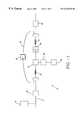
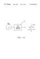
- FIG. 1is a schematic diagram of one embodiment of a multi-stage optical amplifier of the present invention that includes a pump shunt.
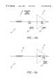
- FIG. 2illustrates that the cutoff wavelength of the fiber used with the present invention should be shorter than the pump and signal wavelengths.
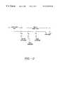
- FIG. 3is a schematic diagram illustrating the inclusion of a dispersion compensating element, a gain equalization element and an add/drop multiplexer to the multi-stage optical amplifier of the present invention.
- FIG. 4is a schematic diagram of another embodiment of a multi-stage optical amplifier of the present invention that includes two pump shunts.
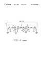
- FIG. 5is a schematic diagram of another embodiment of a multi-stage optical amplifier of the present invention that includes a pump shunt and four lengths of amplifier fiber.
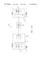
- FIG. 6is a schematic diagram of one embodiment of a multi-stage optical amplifier of the present invention that includes a pump shunt and two pump sources.
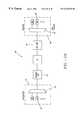
- FIG. 7is a schematic diagram of one embodiment of a multi-stage optical amplifier of the present invention that includes a pump shunt and a circulator.
- FIG. 8 ( a )is a schematic diagram of another embodiment of a multi-stage optical amplifier of the present invention that includes two lengths of Raman amplifier fiber and two pump sources.
- FIG. 8 ( b )is a schematic diagram of an embodiment of the present invention with a discrete and a distributed amplifier; where distributed amplification is added with only counter-propagating Raman pumps
- FIG. 8 ( c )is a schematic diagram of an embodiment of the present invention similar to FIG. 8 ( b ) in which mid-span access is not available but bi-directional pumping is allowed.
- FIG. 9is a schematic diagram of another embodiment of a multi-stage optical amplifier of the present invention that includes three lengths of Raman amplifier fiber and three pump sources.
- FIG. 10is a schematic diagram illustrating four pump source whose outputs are combined using wavelength and polarization multiplexing.
- FIG. 11is a schematic diagram illustrating eight pump source whose outputs are combined using wavelength and polarization multiplexing.
- FIG. 12is a schematic diagram illustrating that Brillouin threshold for a laser diode pump source can be minimized with the inclusion of a spectrum broadening device.
- FIG. 13is a schematic diagram of a broadband booster amplifier embodiment of the present invention.
- FIG. 14is a schematic diagram of a broadband pre-amplifier embodiment of the present invention.
- FIG. 15is a schematic diagram of one embodiment of a broadband communication system of the present invention.
- FIG. 16is a schematic diagram of another embodiment of a broadband communication system of the present invention.
- FIG. 17is a schematic diagram of another embodiment of a broadband communication system of the present invention.
- FIG. 18is a schematic diagram of another embodiment of a broadband communication system of the present invention.
- FIG. 19is a schematic diagram of another embodiment of a broadband communication system of the present invention.
- One embodiment of the present inventionis a multi-stage optical amplifier 10 with an optical fiber 12 including a first length of amplifier fiber 14 and a second length of amplifier fiber 16 .
- Optical fiber 12is configured to be coupled to a signal source 18 that produces at least a signal wavelength ⁇ s and a pump source 20 that produces a pump wavelength ⁇ p .
- Pump wavelength ⁇ pis less than signal wavelength ⁇ s .
- Signal input port 22 , signal output port 24 and pump input port 26are each coupled to optical fiber 12 .
- a first lossy member 28is coupled to optical fiber 12 and positioned between the first and second lengths of amplifier fiber 14 and 16 respectively.
- a pump shunt 30is coupled to signal input port 22 and signal output port 24 .
- a second lossy member 32is coupled to pump shunt 30 .
- Pump shunt 30can be an optical fiber that is integral with optical fiber 12 or a separate optical fiber.
- Pump beam ⁇ ppropagates towards signal input port 22 from first length of amplifier fiber 14 and away from signal input port 22 to second length of amplifier fiber 16 .
- First and second lengths of amplifier fiber 14 and 16each preferably have a length greater than or equal to 200 m.
- Pump wavelength ⁇ pis preferably in the range of 1300 nm to 1530 nm, and the signal wavelength can be in the range of 1430 to 1530 nm.
- Suitable pump sources 20include but are not limited to laser diodes (LD's), solid state lasers, fiber-based cascaded Raman wavelength shifters, cladding pumped fiber lasers and the like.
- First lossy member 28can be an optical isolator, an add/drop multiplexer. a gain equalization member, a dispersion compensation element and the like.
- One or both of first and second lengths of amplifier fiber 14 and 16can be Raman amplifiers. Lossy elements 28 can also be placed before and after first and second lengths of amplifier fiber 14 and 16 to prevent disturbance of amplifier performance from spurious reflections from the transmission line. Additionally, a second lossy element 32 can be inserted into pump shunt 30 to reduce the multi-path interference of the signal beam in amplifiers 12 and 14 .
- first and second lengths of amplifier fiber 14 and 16can be implemented in dispersion compensating fiber (DCF).
- DCFdispersion compensating fiber
- a DCFis a fiber whose zero dispersion point is shifted to wavelengths much longer than 1500 nm using the waveguide dispersion property. Consequently, DCF tend to have a small affective core area and significant germanium doping in the core, both of which lead to an enhancement of the Raman gain coefficient.
- DCF'sare generally added periodically to a high-speed transmission link to compensate for the dispersion accumulated in the line.
- multi-stage optical amplifier 10operates in a violet band between 1430 and 1530 nm.
- Fiber 12is a DSF with at least one fiber non-linearity effect and a zero dispersion wavelength.
- multi-stage optical amplifier 10provides gain in the violet band sufficiently far from the zero dispersion wavelength to avoid non-linearity effects.
- First length of amplifier fiber 14preferably has lower noise than second length of amplifier fiber 16 .
- Second length of amplifier fiber 16has a higher gain than first length of amplifier fiber 14 .
- first length of amplifier fiber 14has an optical noise figure of less than 8 dB
- second length of amplifier fiber 16has a gain level of at least 5 dB.
- WDM couplers 34are used to couple a pump path from the signal input port 22 to the signal output port 24 .
- WDM couplers 34are designed to pass (couple over) the signal band while coupling over (passing) the pump beams.
- Exemplary WDM couplers 34include fused-tapered fiber couplers, Mach-Zehnder couplers, thin-film dielectric filters, bulk diachronic elements and the like.
- Signal input port 22inputs signal ⁇ s which is amplified through Raman scattering when first and second lengths of amplifier fiber 14 and 16 are Raman amplifiers.
- the dispersion and length of the first and second lengths of amplifier fiber 14 and 16can be selected to be of the same magnitude of dispersion-length product as the transmission link but of the opposite sign of dispersion.
- First and second lengths of amplifier fiber 14 and 16are preferably made single spatial mode for pump source 20 and signal wavelengths by making the cut-off wavelength of the gain fiber shorter than the pump wavelength.
- the cut-off wavelengthis the wavelength below which first and second lengths of amplifier fiber 14 and 16 support more than one mode or becomes multi-mode. If the pump or signal falls into the multi-mode region, then additional noise arising from the beating between different modes may arise.
- the fiber cut-off wavelengthshould be shorter than the pump wavelength ⁇ p .
- Pump wavelength ⁇ pis shorter than signal wavelength ⁇ s .
- Multi-stage optical amplifier 10is pumped so the net gain equals or exceeds the sum of losses in the transmission link and first and second lengths of amplifier fiber 14 and 16 .
- FIG. 3illustrates that a dispersion compensating element 33 , gain equalization element 29 or an add/drop multiplexer 31 can be included and positioned between first and second lengths of amplifier fiber 14 and 16 .
- FIG. 4illustrates an embodiment of multi-stage optical amplifier 10 with a third length of amplifier fiber 42 .
- Second lossy member 32is positioned between second and third lengths of amplifier fiber 16 and 42 .
- a second pump shuntis coupled to second and third WDM couplers 46 and 48 . Additional lengths of amplifier fiber can also be included.
- multi-stage optical amplifier 10can include a third and a fourth length of amplifier fiber 42 and 50 , respectively.
- third and fourth lengths of amplifier fiber 42 and 50are coupled to pump shunt 30 .
- Second lossy member 32is positioned between third and fourth lengths of amplifier fiber 42 and 50 .
- pump source 20is positioned between first length of amplifier fiber 14 and first lossy member 28 .
- a second pump source 52is positioned between second length of amplifier fiber 16 and signal output port 24 and is coupled to a second pump input port 54 .
- First pump source 20produces a pump beam of wavelength ⁇ p1 and second pump source 52 produces 52 a pump beam of wavelength ⁇ p2 .
- Wavelength ⁇ p1 and wavelength ⁇ p2can be the same or different.
- Pump sources 20 and 44collectively produce a pump beam of wavelength ⁇ p .
- Pump wavelength ⁇ pis less than a signal wavelength ⁇ s .
- multi-stage amplifier 10includes one or more circulators 56 to provide isolation between the first and second lengths of amplifier fiber 14 and 16 .
- Circulator 56also is useful as a means of dumping the remaining pump which can be reused elsewhere for monitoring purposes.
- multi-stage optical amplifier 10can have an open loop configuration,
- optical fiber 12is pumped by a pump beam generated by pump sources 20 and 52 and first and second lengths of amplifier fiber 14 and 16 are each Raman amplifiers.
- Optical fiber 12is preferably single spatial mode at both the signal and pump wavelengths. Again, wavelength ⁇ p1 and wavelength ⁇ p2 can be the same or different.
- the pump beamhas a wavelength shorter than the signal wavelengths.
- Pump sources 20 and 52collectively produce a pump beam of wavelength ⁇ p .
- An amplified signalis then output through signal output port 24 .
- Pump sources 20 and 52are coupled in through WDM couplers 34 and 58 which transmit signal wavelength ⁇ s but couple over the pump wavelength ⁇ p .
- First lossy member 28is positioned between pump input port 26 and signal output port 24 .
- the signalflows in a first direction and the pump beam flows in a reverse direction relative to the first direction.
- First and second lengths of amplifier fiber 14 and 16are pumped in a counter-propagating manner. It may also be desirous to have bi-directional pumping in second length of amplifier fiber 16 to increase the power amplifier gain without severely impacting the noise figure of multi-stage optical amplifier 10 .
- dispersion compensating element 33may be included and positioned between first and second lengths of amplifier fiber 14 and 16 .
- gain equalization element and add/drop multiplexer 31may be included and positioned between first and second lengths of amplifier fiber 14 and 16 .
- first length of amplifier fiber 14is a distributed Raman amplifier fiber and second length of amplifier fiber 16 is a discrete Raman amplifier fiber.
- a distributed Raman amplifier fiberis an amplifier where at least some part of the transmission link is pumped and involved in amplification.
- first lossy member 28is not positioned between first and second lengths of amplifier fiber 14 and 16 .
- distributed amplificationis added with only counter-propagating Raman pumps. When access at a mid-point stage exists alternate band pumps are added at different spatial points to minimize nonlinear interaction between pumps. In FIG. 8 ( c ) mid-span access is not available but bi-directional pumping is allowed. The embodiment of FIG. 8 ( c ) can be used where alternate band Raman pumps are launched in different directions in order to minimize interaction between pumps.
- the open loop embodiment of multi-stage optical amplifier 10can have three or more lengths of amplifier fiber. Referring now to FIG. 9, an embodiment of multi-stage optical amplifier 10 is illustrated with third length of amplifier fiber 42 coupled to a third pump source 60 which is turn is coupled to a third pump input port 62 . WDM coupler 64 is coupled to third pump input port 62 . Some or all of first, second and third pump sources 20 , 52 and 60 can be laser diode sources. Pump source 60 produces a pump beam of wavelength ⁇ p3 . Wavelengths ⁇ p1 , ⁇ p2 and ⁇ p3 can be the same or different. Pump sources 20 , 44 and 60 collectively produce pump beam of wavelength ⁇ p . An amplified signal is then output through signal output port 24 .
- each of pump source 20 , 52 and 60can include multiple pump sources whose outputs can be combined using wavelength and polarization multiplexing. Multiple combination ratings 66 and PBS's 68 can be utilized. Additionally, some or all of the multiple pump sources which comprise pump sources 20 , 52 and 60 can be laser diodes.
- a spectrum broadening device 70can be coupled to each pump source 20 , 52 and 60 . This is particularly useful for laser diode pump sources.
- Spectrum broadening device 70broadens the spectrum while minimizing Brillouin threshold.
- Suitable spectrum broadening devices 70include but are not limited to, (i)a grating that is sufficiently broadband that can be chirped and cascade individual wavelengths, (ii) positioning a grating in a laser diode external cavity to cause appropriate line broadening and (iii) a dithering drive. Additionally pump pulsing can be used to broaden the spectrum.
- P 0 LDpower of laser diode
- L eff1 ⁇ ⁇ [ 1 - exp - ⁇ ⁇ L ] ⁇ ⁇ effective ⁇ ⁇ pumping ⁇ ⁇ length
- a effeffective area of fiber 12
- g ⁇ B⁇ ⁇ ⁇ ⁇ B ⁇ ⁇ ⁇ B + ⁇ ⁇ ⁇ ⁇ P ⁇ g B
- g ⁇ B⁇ ⁇ ⁇ ⁇ B ⁇ ⁇ ⁇ ⁇ B + ⁇ ⁇ ⁇ ⁇ P ⁇ g B
- Multi-stage optical amplifier 10can be an in-line broadband amplifier, a booster amplifier, a broadband pre-amplifier and incorporated in any variety of different broadband communication systems.
- the present inventionis a broadband booster amplifier 72 that includes a multi-stage optical amplifier 10 coupled to a transmitter 73 .
- Transmitter 73can include a WDM combiner 74 and a plurality of transmitters 76 .
- the plurality of transmitters 76transmit a plurality of wavelengths.
- the plurality of wavelengthsmay include at least a first band of wavelengths and a second band of wavelengths.
- a variety of different transmitters 76can be utilized including but not limited to laser diodes, tunable lasers, or broadband sources such as continuum sources or light-emitting diodes.
- FIG. 14illustrates a broadband pre-amplifier embodiment of the present invention.
- Broadband pre-amplifier 78includes multi-stage optical amplifier 10 coupled to a receiver 80 .
- Receiver 80can include a WDM splitter 82 coupled to a plurality of receivers 84 .
- Suitable receivers 84include but are not limited to germanium or InGaAs or InGaAsP detectors followed by electronics well known to those skilled in the art.
- the present inventionis a broadband communication system 86 .
- multi-stage optical amplifier 10is an in-line broadband amplifier.
- Multi-stage optical amplifier 10is coupled to one or more transmitters 73 and one or more receivers 80 .
- FIG. 16illustrates another embodiment of the present invention which is a broadband communication system 88 that includes multi-stage optical amplifier 10 coupled to a broadband pre-amplifier 90 .
- Multi-stage optical amplifier 10is coupled to one or more transmitters 73 and broadband pre-amplifier 90 is coupled to one or more receivers 80 .
- FIG. 17illustrates yet another embodiment of a broadband communication system 92 with a broadband booster amplifier 94 coupled to multi-stage optical amplifier 10 .
- One or more transmitters 73is coupled to broadband booster amplifier 94 .
- One or more receivers 80is coupled to multi-stage optical amplifier 10 .
- FIG. 18Another embodiment of a broadband communication system 96 is illustrated in FIG. 18 .
- an in-line amplifier 98is coupled to receiver 80 and to a transmitter 100 .
- Transmitterincludes multi-stage optical amplifier 10 coupled to transmitter 73 .
- FIG. 19illustrates another broadband communication system 102 of the present invention.
- Broadband communication system 102includes multi-stage optical amplifier 10 coupled to broadband booster amplifier 94 and broadband pre-amplifier 90 .
- Broadband booster amplifier 94is coupled to one or more transmitters 73 .
- Broadband pre-amplifier 90is coupled to one or more receivers 80 .
Landscapes
- Physics & Mathematics (AREA)
- Electromagnetism (AREA)
- Engineering & Computer Science (AREA)
- Plasma & Fusion (AREA)
- Optics & Photonics (AREA)
- Optical Modulation, Optical Deflection, Nonlinear Optics, Optical Demodulation, Optical Logic Elements (AREA)
- Optical Communication System (AREA)
- Lasers (AREA)
Abstract
Description


Claims (44)
Priority Applications (4)
| Application Number | Priority Date | Filing Date | Title |
|---|---|---|---|
| US09/471,753US6359725B1 (en) | 1998-06-16 | 1999-12-23 | Multi-stage optical amplifier and broadband communication system |
| US10/005,472US6954303B2 (en) | 1999-12-23 | 2001-11-06 | Multi-stage optical amplifier and broadband communication system |
| US10/014,839US6885498B2 (en) | 1998-06-16 | 2001-12-10 | Multi-stage optical amplifier and broadband communication system |
| US10/007,643US6603594B2 (en) | 1998-06-16 | 2002-03-19 | Multi-stage optical amplifier and broadband communication system |
Applications Claiming Priority (1)
| Application Number | Priority Date | Filing Date | Title |
|---|---|---|---|
| US09/471,753US6359725B1 (en) | 1998-06-16 | 1999-12-23 | Multi-stage optical amplifier and broadband communication system |
Related Parent Applications (1)
| Application Number | Title | Priority Date | Filing Date |
|---|---|---|---|
| US09/471,753Continuation-In-PartUS6359725B1 (en) | 1998-06-16 | 1999-12-23 | Multi-stage optical amplifier and broadband communication system |
Related Child Applications (4)
| Application Number | Title | Priority Date | Filing Date |
|---|---|---|---|
| US09/471,753Continuation-In-PartUS6359725B1 (en) | 1998-06-16 | 1999-12-23 | Multi-stage optical amplifier and broadband communication system |
| US10/005,472ContinuationUS6954303B2 (en) | 1999-12-23 | 2001-11-06 | Multi-stage optical amplifier and broadband communication system |
| US10/014,839Continuation-In-PartUS6885498B2 (en) | 1998-06-16 | 2001-12-10 | Multi-stage optical amplifier and broadband communication system |
| US10/007,643ContinuationUS6603594B2 (en) | 1998-06-16 | 2002-03-19 | Multi-stage optical amplifier and broadband communication system |
Publications (1)
| Publication Number | Publication Date |
|---|---|
| US6335820B1true US6335820B1 (en) | 2002-01-01 |
Family
ID=23872863
Family Applications (2)
| Application Number | Title | Priority Date | Filing Date |
|---|---|---|---|
| US09/471,747Expired - LifetimeUS6335820B1 (en) | 1998-06-16 | 1999-12-23 | Multi-stage optical amplifier and broadband communication system |
| US10/005,472Expired - LifetimeUS6954303B2 (en) | 1999-12-23 | 2001-11-06 | Multi-stage optical amplifier and broadband communication system |
Family Applications After (1)
| Application Number | Title | Priority Date | Filing Date |
|---|---|---|---|
| US10/005,472Expired - LifetimeUS6954303B2 (en) | 1999-12-23 | 2001-11-06 | Multi-stage optical amplifier and broadband communication system |
Country Status (1)
| Country | Link |
|---|---|
| US (2) | US6335820B1 (en) |
Cited By (49)
| Publication number | Priority date | Publication date | Assignee | Title |
|---|---|---|---|---|
| US20020021489A1 (en)* | 2000-08-07 | 2002-02-21 | Alcatel | Optical amplification |
| US6384963B2 (en)* | 2000-03-03 | 2002-05-07 | Lucent Technologies Inc. | Optical communication system with co-propagating pump radiation for raman amplification |
| US6417959B1 (en)* | 2000-12-04 | 2002-07-09 | Onetta, Inc. | Raman fiber amplifier |
| US6473223B1 (en)* | 2001-05-01 | 2002-10-29 | Nortel Networks Limited | Raman amplifier |
| US6504973B1 (en)* | 2002-03-16 | 2003-01-07 | Fitel Usa Corp. | Raman amplified dispersion compensating modules |
| US6525869B1 (en)* | 2001-04-30 | 2003-02-25 | Nortel Networks Limited | Raman amplifier |
| US6532101B2 (en) | 2001-03-16 | 2003-03-11 | Xtera Communications, Inc. | System and method for wide band Raman amplification |
| US20030053192A1 (en)* | 2001-08-03 | 2003-03-20 | Islam Mohammed N. | Co-propagating raman amplifiers |
| US20030058899A1 (en)* | 1996-12-23 | 2003-03-27 | Xtera Communications, Inc., A Delaware Corporation | Optical amplification using polarization diversity pumping |
| US6567430B1 (en) | 1998-09-21 | 2003-05-20 | Xtera Communications, Inc. | Raman oscillator including an intracavity filter and amplifiers utilizing same |
| US6574037B2 (en) | 1998-06-16 | 2003-06-03 | Xtera Communications, Inc. | All band amplifier |
| US6580548B2 (en) | 1998-03-24 | 2003-06-17 | Xtera Communications, Inc. | Broadband amplifier and communication system |
| US6587259B2 (en) | 2001-07-27 | 2003-07-01 | Xtera Communications, Inc. | System and method for controlling noise figure |
| US6587260B2 (en)* | 2001-04-09 | 2003-07-01 | Hitachi, Ltd. | Band-expanding method for optical amplifiers and optical transmission apparatus |
| US6594071B1 (en) | 2001-10-02 | 2003-07-15 | Xtera Communications, Inc. | Method and apparatus for amplifier control |
| US6600592B2 (en)* | 1998-03-24 | 2003-07-29 | Xtera Communications, Inc. | S+ band nonlinear polarization amplifiers |
| US6600595B2 (en)* | 2000-02-16 | 2003-07-29 | Nec Corporation | Multi-stage optical amplifier apparatus having fiber grating with a cutoff wavelength less than the pump light wavelength |
| US6603594B2 (en) | 1998-06-16 | 2003-08-05 | Xtera Communications, Inc. | Multi-stage optical amplifier and broadband communication system |
| US6606187B1 (en) | 1998-03-24 | 2003-08-12 | The Regents Of The University Of Michigan | Nonlinear fiber amplifiers used for a 1430-1530 nm low-loss window in optical fibers |
| US6618192B2 (en) | 1998-06-16 | 2003-09-09 | Xtera Communications, Inc. | High efficiency raman amplifier |
| US20030169481A1 (en)* | 2002-03-07 | 2003-09-11 | Hwang Seong-Taek | Dispersion-compensated erbium-doped fiber amplifier |
| US6631028B1 (en) | 1998-03-24 | 2003-10-07 | Xtera Communications, Inc. | Broadband amplifier and communication system |
| US6631025B2 (en) | 2000-01-12 | 2003-10-07 | Xtera Communications, Inc. | Low-noise distributed Raman amplifier using bi-directional pumping using multiple Raman orders |
| US6674566B2 (en)* | 2000-10-05 | 2004-01-06 | Nortel Networks Limited | Raman amplification |
| US6693737B2 (en) | 1998-03-24 | 2004-02-17 | Xtera Communications, Inc. | Dispersion compensating nonlinear polarization amplifiers |
| US20040042061A1 (en)* | 2002-08-30 | 2004-03-04 | Islam Mohammed N. | Controlling ASE in optical amplification stages implementing time modulated pump signals |
| US20040052486A1 (en)* | 2002-09-13 | 2004-03-18 | Fitel Usa Corp. | Optical fibers and modules for dispersion compensation with simultaneous raman amplification |
| US6744553B1 (en) | 2000-06-20 | 2004-06-01 | Xtera Communications, Inc. | System and method for converting a plurality of wavelengths |
| US6751371B1 (en)* | 2001-12-06 | 2004-06-15 | Xtera Communications, Inc. | Method and apparatus for optical element management |
| US6760148B2 (en) | 1998-03-24 | 2004-07-06 | Xtera Communications, Inc. | Nonlinear polarization amplifiers in nonzero dispersion shifted fiber |
| US6778321B1 (en) | 2002-03-15 | 2004-08-17 | Xtera Communications, Inc. | Fiber optic transmission system for a metropolitan area network |
| US6810214B2 (en) | 2001-03-16 | 2004-10-26 | Xtera Communications, Inc. | Method and system for reducing degradation of optical signal to noise ratio |
| US6813065B2 (en)* | 2000-08-18 | 2004-11-02 | Sumitomo Electric Industries, Ltd. | Raman amplifier and optical communication system |
| US6813066B2 (en) | 1998-03-24 | 2004-11-02 | The Regents Of The University Of Michigan | Gain control in nonlinear fiber amplifier stages |
| US6819478B1 (en) | 2002-03-15 | 2004-11-16 | Xtera Communications, Inc. | Fiber optic transmission system with low cost transmitter compensation |
| US6819479B1 (en) | 2001-12-20 | 2004-11-16 | Xtera Communications, Inc. | Optical amplification using launched signal powers selected as a function of a noise figure |
| US6825973B1 (en) | 2002-03-15 | 2004-11-30 | Xtera Communications, Inc. | Reducing leading edge transients using co-propagating pumps |
| US6885498B2 (en) | 1998-06-16 | 2005-04-26 | Xtera Communications, Inc. | Multi-stage optical amplifier and broadband communication system |
| US6914717B1 (en) | 1996-12-23 | 2005-07-05 | Xtera Communications, Inc. | Multiple wavelength pumping of raman amplifier stages |
| US6924926B2 (en) | 2001-08-03 | 2005-08-02 | Xtera Communications, Inc. | Laser diode pump sources |
| US6954303B2 (en) | 1999-12-23 | 2005-10-11 | Xtera Communications, Inc. | Multi-stage optical amplifier and broadband communication system |
| US6985283B1 (en) | 1998-06-16 | 2006-01-10 | Xtera Communications, Inc. | Fiber-optic compensation for dispersion, gain tilt, and band pump nonlinearity |
| US7058311B1 (en) | 2002-03-15 | 2006-06-06 | Xtera Communications, Inc. | System and method for dispersion compensation in an optical communication system |
| US7068938B1 (en) | 2002-03-15 | 2006-06-27 | Xtera Communications, Inc. | Band optical add/drop multiplexing |
| US20060193035A1 (en)* | 2005-02-17 | 2006-08-31 | Optovia Corporation | Optical Amplification System For Variable Span Length WDM Optical Communication Systems |
| US7197245B1 (en) | 2002-03-15 | 2007-03-27 | Xtera Communications, Inc. | System and method for managing system margin |
| US7254337B1 (en) | 2006-05-16 | 2007-08-07 | Xtera Communications, Inc. | Band optical add/drop multiplexing |
| US20110141553A1 (en)* | 1998-07-23 | 2011-06-16 | Furukawa Electric Co., Ltd. | Raman amplifier, optical repeater, and raman amplification method |
| CN114784601A (en)* | 2022-03-16 | 2022-07-22 | 深圳朗光科技有限公司 | Power Amplification Equipment and Fiber Lasers |
Families Citing this family (3)
| Publication number | Priority date | Publication date | Assignee | Title |
|---|---|---|---|---|
| US6901190B1 (en)* | 2001-01-25 | 2005-05-31 | Tyco Telecommunications (Us) Inc. | Fault tolerant optical amplifier configuration using pump feedthrough |
| US7787772B2 (en)* | 2005-01-28 | 2010-08-31 | Canare Electric Co., Ltd. | Optical signal transmission device and optical communication network |
| EP1753161A1 (en)* | 2005-08-08 | 2007-02-14 | Alcatel | Raman-amplified optical transmission system and method for amplifying optical signals |
Citations (84)
| Publication number | Priority date | Publication date | Assignee | Title |
|---|---|---|---|---|
| US4063106A (en) | 1977-04-25 | 1977-12-13 | Bell Telephone Laboratories, Incorporated | Optical fiber Raman oscillator |
| US4616898A (en)* | 1980-03-31 | 1986-10-14 | Polaroid Corporation | Optical communication systems using raman repeaters and components therefor |
| US4685107A (en) | 1986-06-09 | 1987-08-04 | Spectra-Physics, Inc. | Dispersion compensated fiber Raman oscillator |
| US4699452A (en)* | 1985-10-28 | 1987-10-13 | American Telephone And Telegraph Company, At&T Bell Laboratories | Optical communications system comprising Raman amplification means |
| US4740974A (en) | 1984-12-13 | 1988-04-26 | Stc Plc | Optical amplifiers |
| US4831616A (en) | 1987-03-31 | 1989-05-16 | Huber David R | Multiplexed fiber optics wideband data distribution system |
| US5039199A (en) | 1989-12-29 | 1991-08-13 | At&T Bell Laboratories | Lightwave transmission system having remotely pumped quasi-distributed amplifying fibers |
| US5050183A (en) | 1990-11-05 | 1991-09-17 | The United States Of America As Represented By The Secretary Of The Navy | Figure eight shaped coherent optical pulse source |
| US5058974A (en) | 1989-10-06 | 1991-10-22 | At&T Bell Laboratories | Distributed amplification for lightwave transmission system |
| US5107360A (en) | 1990-11-05 | 1992-04-21 | General Instrument Corporation | Optical transmission of RF subcarriers in adjacent signal bands |
| US5117196A (en) | 1989-04-22 | 1992-05-26 | Stc Plc | Optical amplifier gain control |
| US5132976A (en) | 1991-05-28 | 1992-07-21 | At&T Bell Laboratories | Electrically tunable fiber ring laser |
| US5134620A (en) | 1990-11-20 | 1992-07-28 | General Instrument Corporation | Laser with longitudinal mode selection |
| US5140456A (en) | 1991-04-08 | 1992-08-18 | General Instrument Corporation | Low noise high power optical fiber amplifier |
| US5151908A (en) | 1990-11-20 | 1992-09-29 | General Instrument Corporation | Laser with longitudinal mode selection |
| US5153762A (en) | 1990-03-19 | 1992-10-06 | General Instrument Corporation | Method and apparatus for recovering AM channell signals distributed on an optical fiber |
| US5159601A (en) | 1991-07-17 | 1992-10-27 | General Instrument Corporation | Method for producing a tunable erbium fiber laser |
| US5166821A (en) | 1991-03-12 | 1992-11-24 | General Instrument Corporation | Reduction of non-linear effects in optical fiber communication systems and method of using same |
| US5187760A (en) | 1992-01-23 | 1993-02-16 | General Instrument Corporation | Wavelength selective coupler for high power optical communications |
| US5191586A (en) | 1991-07-18 | 1993-03-02 | General Instrument Corporation | Narrow band incoherent optical carrier generator |
| US5191628A (en) | 1990-11-09 | 1993-03-02 | Northern Telecom Limited | Optical amplifiers |
| US5200964A (en) | 1991-03-12 | 1993-04-06 | General Instrument Corporation | Broad linewidth lasers for optical fiber communication systems |
| US5208819A (en) | 1992-01-23 | 1993-05-04 | General Instrument Corporation | Optical source with frequency locked to an in-fiber grating resonantor |
| US5210631A (en) | 1989-12-22 | 1993-05-11 | General Instrument Corporation | Transmission of AM-VSB video signals over an optical fiber |
| US5212579A (en) | 1991-03-11 | 1993-05-18 | General Instrument Corporation | Method and apparatus for communicating amplitude modulated signals over an optical communication path |
| US5218655A (en) | 1992-05-29 | 1993-06-08 | At&T Bell Laboratories | Article comprising an optical waveguide with in-line refractive index grating |
| US5222089A (en) | 1992-01-08 | 1993-06-22 | General Instrument Corporation | Optical signal source for overcoming distortion generated by an optical amplifier |
| US5226049A (en) | 1992-02-06 | 1993-07-06 | Amoco Corporation | Optical fiber rare earth ion upconversion laser system |
| US5225925A (en) | 1991-01-23 | 1993-07-06 | Amoco Corporation | Sensitized erbium fiber optical amplifier and source |
| US5243609A (en) | 1990-11-20 | 1993-09-07 | General Instrument Corporation | Laser with longitudinal mode selection |
| US5257124A (en) | 1991-08-15 | 1993-10-26 | General Instrument Corporation | Low distortion laser system for AM fiber optic communication |
| US5268910A (en) | 1991-07-18 | 1993-12-07 | General Instrument Corporation | Superluminescent optical source |
| US5271024A (en) | 1992-07-27 | 1993-12-14 | General Instrument Corporation | Optical fiber amplifier and laser with flattened gain slope |
| US5283686A (en) | 1992-07-27 | 1994-02-01 | General Instrument Corporation, Jerrold Communications | Optical systems with grating reflector |
| US5293545A (en) | 1992-07-27 | 1994-03-08 | General Instrument Corporation | Optical source with reduced relative intensity noise |
| US5295209A (en) | 1991-03-12 | 1994-03-15 | General Instrument Corporation | Spontaneous emission source having high spectral density at a desired wavelength |
| US5295016A (en) | 1991-07-15 | 1994-03-15 | Koninklijke Ptt Nederland, N.V. | Polarization insensitive amplification device |
| US5321707A (en) | 1992-07-27 | 1994-06-14 | General Instrument Corporation | Remote pumping for active optical devices |
| US5321543A (en) | 1992-10-20 | 1994-06-14 | General Instrument Corporation | Apparatus and method for linearizing an external optical modulator |
| US5323404A (en) | 1993-11-02 | 1994-06-21 | At&T Bell Laboratories | Optical fiber laser or amplifier including high reflectivity gratings |
| US5359612A (en) | 1993-09-29 | 1994-10-25 | The United States Of America As Represented By The Secretary Of The Navy | High repetition rate, mode locked, figure eight laser with extracavity feedback |
| US5373389A (en) | 1992-10-27 | 1994-12-13 | General Instrument Corporation | Method for linearizing an unbalanced Mach Zehnder optical frequency discriminator |
| US5389779A (en) | 1993-07-29 | 1995-02-14 | At&T Corp. | Method and apparatus for near-field, scanning, optical microscopy by reflective, optical feedback |
| US5400166A (en) | 1992-10-20 | 1995-03-21 | General Instrument Corporation | Communication of signals sharing a single optical source |
| US5416629A (en) | 1992-12-02 | 1995-05-16 | General Instrument Corporation | Intensity modulated digital optical communications using a frequency modulated signal laser |
| US5450427A (en) | 1994-10-21 | 1995-09-12 | Imra America, Inc. | Technique for the generation of optical pulses in modelocked lasers by dispersive control of the oscillation pulse width |
| US5467212A (en) | 1993-06-04 | 1995-11-14 | Huber; David R. | Addressable grating modulation system for optical cable TV system |
| US5473622A (en) | 1994-12-29 | 1995-12-05 | At&T Corp. | Cladding-pumped MOPA structure |
| US5477555A (en) | 1993-01-28 | 1995-12-19 | France Telecom Etablissement Autonome De Droit Public | Method and device for generating optical pulses |
| US5479291A (en) | 1991-09-03 | 1995-12-26 | British Telecommunications Plc | Non-linear optical interferometer with saturated amplifier |
| US5485481A (en) | 1994-06-28 | 1996-01-16 | Seastar Optics Inc. | Fibre-grating-stabilized diode laser |
| US5497386A (en) | 1993-09-16 | 1996-03-05 | Pirelli Cavi S.P.A. | Optical-fibre passively mode locked laser generator with non-linear polarization switching |
| US5504771A (en) | 1992-11-03 | 1996-04-02 | California Institute Of Technology | Fiber-optic ring laser |
| US5504609A (en) | 1995-05-11 | 1996-04-02 | Ciena Corporation | WDM optical communication system with remodulators |
| US5513194A (en) | 1994-06-30 | 1996-04-30 | Massachusetts Institute Of Technology | Stretched-pulse fiber laser |
| US5521738A (en) | 1994-06-30 | 1996-05-28 | At&T Corp. | Data encoded optical pulse generator |
| US5530710A (en) | 1995-05-15 | 1996-06-25 | At&T Corp. | High-power pumping of three-level optical fiber laser amplifier |
| US5532864A (en) | 1995-06-01 | 1996-07-02 | Ciena Corporation | Optical monitoring channel for wavelength division multiplexed optical communication system |
| US5541947A (en) | 1995-05-10 | 1996-07-30 | The Regents Of The University Of Michigan | Selectively triggered, high contrast laser |
| US5542011A (en) | 1993-09-09 | 1996-07-30 | Northern Telecom Limited | Optical amplifiers |
| US5577057A (en) | 1991-03-01 | 1996-11-19 | Telstra Corporation Limited | Modelocked lasers |
| US5600473A (en) | 1993-06-04 | 1997-02-04 | Ciena Corporation | Optical amplifier systems with add/drop multiplexing |
| US5623508A (en)* | 1996-02-12 | 1997-04-22 | Lucent Technologies Inc. | Article comprising a counter-pumped optical fiber raman amplifier |
| US5659559A (en) | 1994-06-28 | 1997-08-19 | Sdl, Inc. | Apparatus for generating a stabilized laser source |
| US5659644A (en) | 1996-06-07 | 1997-08-19 | Lucent Technologies Inc. | Fiber light source with multimode fiber coupler |
| US5673280A (en)* | 1996-02-12 | 1997-09-30 | Lucent Technologies Inc. | Article comprising low noise optical fiber raman amplifier |
| US5673281A (en) | 1996-04-20 | 1997-09-30 | Board Of Trustees Of The Leland Stanford Junior University | Solid state system for frequency conversion using raman-active media and non-linear media |
| US5726784A (en) | 1995-05-11 | 1998-03-10 | Ciena Corp. | WDM optical communication system with remodulators and diverse optical transmitters |
| US5734665A (en) | 1995-12-07 | 1998-03-31 | Electronics And Telecommunications Research Institute | Optical fiber laser |
| WO1998020587A1 (en) | 1996-11-01 | 1998-05-14 | Tyco Submarine Systems Ltd. | A multi-wavelength optical pump |
| US5757541A (en) | 1997-01-15 | 1998-05-26 | Litton Systems, Inc. | Method and apparatus for an optical fiber amplifier |
| US5768012A (en) | 1997-03-07 | 1998-06-16 | Sdl, Inc. | Apparatus and method for the high-power pumping of fiber optic amplifiers |
| US5778014A (en)* | 1996-12-23 | 1998-07-07 | Islam; Mohammed N. | Sagnac raman amplifiers and cascade lasers |
| US5815518A (en)* | 1997-06-06 | 1998-09-29 | Lucent Technologies Inc. | Article comprising a cascaded raman fiber laser |
| US5825520A (en) | 1992-07-27 | 1998-10-20 | Huber; David R. | Optical demultiplexers with grating reflectors |
| US5838700A (en) | 1995-07-28 | 1998-11-17 | Nauchny Tsentr Volokonnoi Optiki Pri Institute Obschei Fiziki Rossiiskoi Akademii Nauk | Raman fibre laser, bragg fibre-optical grating and method for changing the refraction index in germanium silicate glass |
| US5841797A (en) | 1994-06-28 | 1998-11-24 | Ventrudo; Brian F. | Apparatus for stabilizing multiple laser sources and their application |
| US5847862A (en) | 1995-06-12 | 1998-12-08 | Lucent Technologies Incorporated | Multi-channel optical fiber communication system |
| US5861981A (en) | 1997-08-20 | 1999-01-19 | Ditech Corporation | Optical amplifier having dynamically shaped gain |
| US5880866A (en) | 1996-11-13 | 1999-03-09 | At&T Corp | Time division demultiplexing using selective Raman amplification |
| US5883736A (en) | 1996-02-23 | 1999-03-16 | The Furukawa Electric Co., Ltd. | Er-doped optical fiber amplifier |
| US5887093A (en) | 1997-09-12 | 1999-03-23 | Lucent Technologies Incorporated | Optical fiber dispersion compensation |
| EP0903876A1 (en) | 1997-08-28 | 1999-03-24 | Lucent Technologies Inc. | Optical fiber communication system with a distributed raman amplifier and a remotely pumped er-doped fiber amplifier |
| US5920423A (en) | 1997-12-05 | 1999-07-06 | Sdl, Inc. | Multiple pumped fiber amplifiers for WDM communication systems with adjustment for the amplifier signal gain bandwidth |
Family Cites Families (49)
| Publication number | Priority date | Publication date | Assignee | Title |
|---|---|---|---|---|
| US4715679A (en)* | 1981-12-07 | 1987-12-29 | Corning Glass Works | Low dispersion, low-loss single-mode optical waveguide |
| US4995690A (en) | 1989-04-24 | 1991-02-26 | Islam Mohammed N | Modulation instability-based fiber interferometric switch |
| US4932739A (en) | 1989-09-25 | 1990-06-12 | At&T Bell Laboratories | Ultra-fast optical logic devices |
| US5020050A (en) | 1989-10-13 | 1991-05-28 | At&T Bell Laboratories | Cascadable optical combinatorial logic gates |
| US5078464A (en) | 1990-11-07 | 1992-01-07 | At&T Bell Laboratories | Optical logic device |
| US5101456A (en) | 1990-11-07 | 1992-03-31 | At&T Bell Laboratories | Predistortion apparatus for optical logic device |
| US5224194A (en) | 1991-04-02 | 1993-06-29 | At&T Bell Laboratories | All-optical timing restoration |
| US5115488A (en) | 1991-04-02 | 1992-05-19 | At&T Bell Laboratories | Apparatus comprising an all-optical gate |
| JP3373333B2 (en) | 1994-09-12 | 2003-02-04 | Kddi株式会社 | Optical amplification repeater transmission system |
| US5485536A (en) | 1994-10-13 | 1996-01-16 | Accuphotonics, Inc. | Fiber optic probe for near field optical microscopy |
| US5664036A (en) | 1994-10-13 | 1997-09-02 | Accuphotonics, Inc. | High resolution fiber optic probe for near field optical microscopy and method of making same |
| US6191877B1 (en) | 1995-02-17 | 2001-02-20 | Lucent Technologies Inc. | WDM optical fiber system using Raman amplification |
| US5559920A (en) | 1995-03-01 | 1996-09-24 | Lucent Technologies Inc. | Dispersion compensation in optical fiber communications |
| DE69637562D1 (en)* | 1995-03-20 | 2008-07-24 | Fujitsu Ltd | Method and device for optical signal processing |
| US5796909A (en) | 1996-02-14 | 1998-08-18 | Islam; Mohammed N. | All-fiber, high-sensitivity, near-field optical microscopy instrument employing guided wave light collector and specimen support |
| US5959750A (en) | 1996-06-06 | 1999-09-28 | Lucent Technologies Inc. | Method of upgrading transmission capacity by Raman amplification |
| US5790300A (en) | 1996-10-15 | 1998-08-04 | Mcdonnell Douglas Corporation | Multi-channel fiber amplification system and associated method |
| EP0848463A3 (en) | 1996-12-11 | 1999-07-28 | Nippon Telegraph And Telephone Corporation | Optical fibre amplifier and optical amplification method |
| US6052393A (en) | 1996-12-23 | 2000-04-18 | The Regents Of The University Of Michigan | Broadband Sagnac Raman amplifiers and cascade lasers |
| EP0968579B1 (en) | 1997-03-17 | 2003-06-04 | JDS Uniphase Corporation | Multiple stage optical fiber amplifier |
| US6191854B1 (en) | 1997-06-23 | 2001-02-20 | Pirelli Cavi E Sistemi S.P.A. | Optical telecommunications system |
| US6043927A (en) | 1997-06-26 | 2000-03-28 | University Of Michigan | Modulation instability wavelength converter |
| US6008933A (en) | 1997-08-19 | 1999-12-28 | Sdl, Inc. | Multiple stage optical fiber amplifier |
| US5978130A (en) | 1997-09-16 | 1999-11-02 | Mci Communications Corporation | Dual-band fiber optic amplification system using a single pump source |
| JP3638777B2 (en) | 1998-02-04 | 2005-04-13 | 富士通株式会社 | Method for gain equalization and apparatus and system used to implement the method |
| US5905838A (en) | 1998-02-18 | 1999-05-18 | Lucent Technologies Inc. | Dual window WDM optical fiber communication |
| US6374006B1 (en) | 1998-03-20 | 2002-04-16 | Xtera Communications, Inc. | Chirped period gratings for raman amplification in circulator loop cavities |
| US6101024A (en) | 1998-03-24 | 2000-08-08 | Xtera Communications, Inc. | Nonlinear fiber amplifiers used for a 1430-1530nm low-loss window in optical fibers |
| US6356384B1 (en) | 1998-03-24 | 2002-03-12 | Xtera Communications Inc. | Broadband amplifier and communication system |
| US6404964B1 (en) | 1998-05-01 | 2002-06-11 | Corning Incorporated | Dispersion managed optical waveguide and system with distributed amplification |
| JP5069825B2 (en) | 1998-06-16 | 2012-11-07 | エクステラ コミュニケイションズ インコーポレイテッド | Optical fiber compensation for dispersion, gain tilt, and band-pumping nonlinearity |
| US6359725B1 (en) | 1998-06-16 | 2002-03-19 | Xtera Communications, Inc. | Multi-stage optical amplifier and broadband communication system |
| US6335820B1 (en) | 1999-12-23 | 2002-01-01 | Xtera Communications, Inc. | Multi-stage optical amplifier and broadband communication system |
| US6344922B1 (en)* | 1998-07-21 | 2002-02-05 | Corvis Corporation | Optical signal varying devices |
| US6151160A (en) | 1998-10-05 | 2000-11-21 | Tyco Submarine Systems Ltd. | Broadband Raman pre-amplifier for wavelength division multiplexed optical communication systems |
| JP2000151507A (en) | 1998-11-09 | 2000-05-30 | Nippon Telegr & Teleph Corp <Ntt> | Optical transmission system |
| US6181464B1 (en) | 1998-12-01 | 2001-01-30 | Tycom (Us) Inc. | Low noise Raman amplifier employing bidirectional pumping and an optical transmission system incorporating same |
| US6163636A (en) | 1999-01-19 | 2000-12-19 | Lucent Technologies Inc. | Optical communication system using multiple-order Raman amplifiers |
| US6381391B1 (en) | 1999-02-19 | 2002-04-30 | The Regents Of The University Of Michigan | Method and system for generating a broadband spectral continuum and continuous wave-generating system utilizing same |
| US6088152A (en) | 1999-03-08 | 2000-07-11 | Lucent Technologies Inc. | Optical amplifier arranged to offset Raman gain |
| US6356383B1 (en) | 1999-04-02 | 2002-03-12 | Corvis Corporation | Optical transmission systems including optical amplifiers apparatuses and methods |
| GB9911665D0 (en) | 1999-05-19 | 1999-07-21 | Cit Alcatel | An optical amplifier |
| JP2001255563A (en)* | 2000-03-08 | 2001-09-21 | Sumitomo Electric Ind Ltd | Optical transmission system |
| US6414786B1 (en) | 2000-03-27 | 2002-07-02 | Tycom (Us) Inc. | Method and apparatus for reducing polarization dependent gain in Raman amplification |
| JP2002014383A (en) | 2000-06-28 | 2002-01-18 | Kdd Submarine Cable Systems Inc | Raman amplifier |
| US6535660B1 (en) | 2000-08-09 | 2003-03-18 | Lucent Technologies Inc. | Raman-amplified optical transmission system |
| US6310716B1 (en) | 2000-08-18 | 2001-10-30 | Corning Incorporated | Amplifier system with a discrete Raman fiber amplifier module |
| US6437906B1 (en) | 2000-11-22 | 2002-08-20 | Cisco Technology, Inc. | All-optical gain controlled L-band EDFA structure with reduced four-wave mixing cross-talk |
| US6417959B1 (en) | 2000-12-04 | 2002-07-09 | Onetta, Inc. | Raman fiber amplifier |
- 1999
- 1999-12-23USUS09/471,747patent/US6335820B1/ennot_activeExpired - Lifetime
- 2001
- 2001-11-06USUS10/005,472patent/US6954303B2/ennot_activeExpired - Lifetime
Patent Citations (93)
| Publication number | Priority date | Publication date | Assignee | Title |
|---|---|---|---|---|
| US4063106A (en) | 1977-04-25 | 1977-12-13 | Bell Telephone Laboratories, Incorporated | Optical fiber Raman oscillator |
| US4616898A (en)* | 1980-03-31 | 1986-10-14 | Polaroid Corporation | Optical communication systems using raman repeaters and components therefor |
| US4740974A (en) | 1984-12-13 | 1988-04-26 | Stc Plc | Optical amplifiers |
| US4699452A (en)* | 1985-10-28 | 1987-10-13 | American Telephone And Telegraph Company, At&T Bell Laboratories | Optical communications system comprising Raman amplification means |
| US4685107A (en) | 1986-06-09 | 1987-08-04 | Spectra-Physics, Inc. | Dispersion compensated fiber Raman oscillator |
| US4831616A (en) | 1987-03-31 | 1989-05-16 | Huber David R | Multiplexed fiber optics wideband data distribution system |
| US5117196A (en) | 1989-04-22 | 1992-05-26 | Stc Plc | Optical amplifier gain control |
| US5058974A (en) | 1989-10-06 | 1991-10-22 | At&T Bell Laboratories | Distributed amplification for lightwave transmission system |
| US5331449A (en) | 1989-12-22 | 1994-07-19 | General Instrument Corporation | Optical fiber tree and branch network for AM signal distribution |
| US5210631A (en) | 1989-12-22 | 1993-05-11 | General Instrument Corporation | Transmission of AM-VSB video signals over an optical fiber |
| US5301054A (en) | 1989-12-22 | 1994-04-05 | General Instrument Corporation | Transmission of AM-VSB video signals over an optical fiber |
| US5039199A (en) | 1989-12-29 | 1991-08-13 | At&T Bell Laboratories | Lightwave transmission system having remotely pumped quasi-distributed amplifying fibers |
| US5153762A (en) | 1990-03-19 | 1992-10-06 | General Instrument Corporation | Method and apparatus for recovering AM channell signals distributed on an optical fiber |
| US5107360A (en) | 1990-11-05 | 1992-04-21 | General Instrument Corporation | Optical transmission of RF subcarriers in adjacent signal bands |
| US5050183A (en) | 1990-11-05 | 1991-09-17 | The United States Of America As Represented By The Secretary Of The Navy | Figure eight shaped coherent optical pulse source |
| US5191628A (en) | 1990-11-09 | 1993-03-02 | Northern Telecom Limited | Optical amplifiers |
| US5243609A (en) | 1990-11-20 | 1993-09-07 | General Instrument Corporation | Laser with longitudinal mode selection |
| US5151908A (en) | 1990-11-20 | 1992-09-29 | General Instrument Corporation | Laser with longitudinal mode selection |
| US5134620A (en) | 1990-11-20 | 1992-07-28 | General Instrument Corporation | Laser with longitudinal mode selection |
| US5225925A (en) | 1991-01-23 | 1993-07-06 | Amoco Corporation | Sensitized erbium fiber optical amplifier and source |
| US5577057A (en) | 1991-03-01 | 1996-11-19 | Telstra Corporation Limited | Modelocked lasers |
| US5212579A (en) | 1991-03-11 | 1993-05-18 | General Instrument Corporation | Method and apparatus for communicating amplitude modulated signals over an optical communication path |
| US5200964A (en) | 1991-03-12 | 1993-04-06 | General Instrument Corporation | Broad linewidth lasers for optical fiber communication systems |
| US5295209A (en) | 1991-03-12 | 1994-03-15 | General Instrument Corporation | Spontaneous emission source having high spectral density at a desired wavelength |
| US5166821A (en) | 1991-03-12 | 1992-11-24 | General Instrument Corporation | Reduction of non-linear effects in optical fiber communication systems and method of using same |
| US5140456A (en) | 1991-04-08 | 1992-08-18 | General Instrument Corporation | Low noise high power optical fiber amplifier |
| US5132976A (en) | 1991-05-28 | 1992-07-21 | At&T Bell Laboratories | Electrically tunable fiber ring laser |
| US5295016A (en) | 1991-07-15 | 1994-03-15 | Koninklijke Ptt Nederland, N.V. | Polarization insensitive amplification device |
| US5159601A (en) | 1991-07-17 | 1992-10-27 | General Instrument Corporation | Method for producing a tunable erbium fiber laser |
| US5191586A (en) | 1991-07-18 | 1993-03-02 | General Instrument Corporation | Narrow band incoherent optical carrier generator |
| US5268910A (en) | 1991-07-18 | 1993-12-07 | General Instrument Corporation | Superluminescent optical source |
| US5257124A (en) | 1991-08-15 | 1993-10-26 | General Instrument Corporation | Low distortion laser system for AM fiber optic communication |
| US5479291A (en) | 1991-09-03 | 1995-12-26 | British Telecommunications Plc | Non-linear optical interferometer with saturated amplifier |
| US5222089A (en) | 1992-01-08 | 1993-06-22 | General Instrument Corporation | Optical signal source for overcoming distortion generated by an optical amplifier |
| US5208819A (en) | 1992-01-23 | 1993-05-04 | General Instrument Corporation | Optical source with frequency locked to an in-fiber grating resonantor |
| US5187760A (en) | 1992-01-23 | 1993-02-16 | General Instrument Corporation | Wavelength selective coupler for high power optical communications |
| US5226049A (en) | 1992-02-06 | 1993-07-06 | Amoco Corporation | Optical fiber rare earth ion upconversion laser system |
| US5218655A (en) | 1992-05-29 | 1993-06-08 | At&T Bell Laboratories | Article comprising an optical waveguide with in-line refractive index grating |
| US5293545A (en) | 1992-07-27 | 1994-03-08 | General Instrument Corporation | Optical source with reduced relative intensity noise |
| US5283686A (en) | 1992-07-27 | 1994-02-01 | General Instrument Corporation, Jerrold Communications | Optical systems with grating reflector |
| US5271024A (en) | 1992-07-27 | 1993-12-14 | General Instrument Corporation | Optical fiber amplifier and laser with flattened gain slope |
| US5321707A (en) | 1992-07-27 | 1994-06-14 | General Instrument Corporation | Remote pumping for active optical devices |
| US5825520A (en) | 1992-07-27 | 1998-10-20 | Huber; David R. | Optical demultiplexers with grating reflectors |
| US5321543A (en) | 1992-10-20 | 1994-06-14 | General Instrument Corporation | Apparatus and method for linearizing an external optical modulator |
| US5400166A (en) | 1992-10-20 | 1995-03-21 | General Instrument Corporation | Communication of signals sharing a single optical source |
| US5373389A (en) | 1992-10-27 | 1994-12-13 | General Instrument Corporation | Method for linearizing an unbalanced Mach Zehnder optical frequency discriminator |
| US5504771A (en) | 1992-11-03 | 1996-04-02 | California Institute Of Technology | Fiber-optic ring laser |
| US5416629A (en) | 1992-12-02 | 1995-05-16 | General Instrument Corporation | Intensity modulated digital optical communications using a frequency modulated signal laser |
| US5477555A (en) | 1993-01-28 | 1995-12-19 | France Telecom Etablissement Autonome De Droit Public | Method and device for generating optical pulses |
| US5555118A (en) | 1993-06-04 | 1996-09-10 | Ciena Corporation | Method for removing and inserting optical carriers in a WDM optical communication system |
| US5659351A (en) | 1993-06-04 | 1997-08-19 | Ciena Corporation | Switch and insertion networks in optical cable TV system |
| US5467212A (en) | 1993-06-04 | 1995-11-14 | Huber; David R. | Addressable grating modulation system for optical cable TV system |
| US5600473A (en) | 1993-06-04 | 1997-02-04 | Ciena Corporation | Optical amplifier systems with add/drop multiplexing |
| US5579143A (en) | 1993-06-04 | 1996-11-26 | Ciena Corporation | Optical system with tunable in-fiber gratings |
| US5701186A (en) | 1993-06-04 | 1997-12-23 | Ciena Corporation | Optical cable TV system |
| US5557442A (en) | 1993-06-04 | 1996-09-17 | Ciena Corporation | Optical amplifiers with flattened gain curves |
| US5389779A (en) | 1993-07-29 | 1995-02-14 | At&T Corp. | Method and apparatus for near-field, scanning, optical microscopy by reflective, optical feedback |
| US5542011A (en) | 1993-09-09 | 1996-07-30 | Northern Telecom Limited | Optical amplifiers |
| US5497386A (en) | 1993-09-16 | 1996-03-05 | Pirelli Cavi S.P.A. | Optical-fibre passively mode locked laser generator with non-linear polarization switching |
| US5359612A (en) | 1993-09-29 | 1994-10-25 | The United States Of America As Represented By The Secretary Of The Navy | High repetition rate, mode locked, figure eight laser with extracavity feedback |
| US5323404A (en) | 1993-11-02 | 1994-06-21 | At&T Bell Laboratories | Optical fiber laser or amplifier including high reflectivity gratings |
| US5841797A (en) | 1994-06-28 | 1998-11-24 | Ventrudo; Brian F. | Apparatus for stabilizing multiple laser sources and their application |
| US5659559A (en) | 1994-06-28 | 1997-08-19 | Sdl, Inc. | Apparatus for generating a stabilized laser source |
| US5485481A (en) | 1994-06-28 | 1996-01-16 | Seastar Optics Inc. | Fibre-grating-stabilized diode laser |
| US5513194A (en) | 1994-06-30 | 1996-04-30 | Massachusetts Institute Of Technology | Stretched-pulse fiber laser |
| US5617434A (en) | 1994-06-30 | 1997-04-01 | Massachusetts Inst. Of Technology | Stretched-pulse fiber laser |
| US5521738A (en) | 1994-06-30 | 1996-05-28 | At&T Corp. | Data encoded optical pulse generator |
| US5450427A (en) | 1994-10-21 | 1995-09-12 | Imra America, Inc. | Technique for the generation of optical pulses in modelocked lasers by dispersive control of the oscillation pulse width |
| US5473622A (en) | 1994-12-29 | 1995-12-05 | At&T Corp. | Cladding-pumped MOPA structure |
| US5541947A (en) | 1995-05-10 | 1996-07-30 | The Regents Of The University Of Michigan | Selectively triggered, high contrast laser |
| US5504609A (en) | 1995-05-11 | 1996-04-02 | Ciena Corporation | WDM optical communication system with remodulators |
| US5726784A (en) | 1995-05-11 | 1998-03-10 | Ciena Corp. | WDM optical communication system with remodulators and diverse optical transmitters |
| US5530710A (en) | 1995-05-15 | 1996-06-25 | At&T Corp. | High-power pumping of three-level optical fiber laser amplifier |
| US5798855A (en) | 1995-06-01 | 1998-08-25 | Ciena Corporation | Optical monitoring channel for wavelength division multiplexed optical communication system |
| US5532864A (en) | 1995-06-01 | 1996-07-02 | Ciena Corporation | Optical monitoring channel for wavelength division multiplexed optical communication system |
| US5847862A (en) | 1995-06-12 | 1998-12-08 | Lucent Technologies Incorporated | Multi-channel optical fiber communication system |
| US5838700A (en) | 1995-07-28 | 1998-11-17 | Nauchny Tsentr Volokonnoi Optiki Pri Institute Obschei Fiziki Rossiiskoi Akademii Nauk | Raman fibre laser, bragg fibre-optical grating and method for changing the refraction index in germanium silicate glass |
| US5734665A (en) | 1995-12-07 | 1998-03-31 | Electronics And Telecommunications Research Institute | Optical fiber laser |
| US5673280A (en)* | 1996-02-12 | 1997-09-30 | Lucent Technologies Inc. | Article comprising low noise optical fiber raman amplifier |
| US5623508A (en)* | 1996-02-12 | 1997-04-22 | Lucent Technologies Inc. | Article comprising a counter-pumped optical fiber raman amplifier |
| US5883736A (en) | 1996-02-23 | 1999-03-16 | The Furukawa Electric Co., Ltd. | Er-doped optical fiber amplifier |
| US5673281A (en) | 1996-04-20 | 1997-09-30 | Board Of Trustees Of The Leland Stanford Junior University | Solid state system for frequency conversion using raman-active media and non-linear media |
| US5659644A (en) | 1996-06-07 | 1997-08-19 | Lucent Technologies Inc. | Fiber light source with multimode fiber coupler |
| WO1998020587A1 (en) | 1996-11-01 | 1998-05-14 | Tyco Submarine Systems Ltd. | A multi-wavelength optical pump |
| US5880866A (en) | 1996-11-13 | 1999-03-09 | At&T Corp | Time division demultiplexing using selective Raman amplification |
| US5778014A (en)* | 1996-12-23 | 1998-07-07 | Islam; Mohammed N. | Sagnac raman amplifiers and cascade lasers |
| US5757541A (en) | 1997-01-15 | 1998-05-26 | Litton Systems, Inc. | Method and apparatus for an optical fiber amplifier |
| US5768012A (en) | 1997-03-07 | 1998-06-16 | Sdl, Inc. | Apparatus and method for the high-power pumping of fiber optic amplifiers |
| US5815518A (en)* | 1997-06-06 | 1998-09-29 | Lucent Technologies Inc. | Article comprising a cascaded raman fiber laser |
| US5861981A (en) | 1997-08-20 | 1999-01-19 | Ditech Corporation | Optical amplifier having dynamically shaped gain |
| EP0903876A1 (en) | 1997-08-28 | 1999-03-24 | Lucent Technologies Inc. | Optical fiber communication system with a distributed raman amplifier and a remotely pumped er-doped fiber amplifier |
| US5887093A (en) | 1997-09-12 | 1999-03-23 | Lucent Technologies Incorporated | Optical fiber dispersion compensation |
| US5920423A (en) | 1997-12-05 | 1999-07-06 | Sdl, Inc. | Multiple pumped fiber amplifiers for WDM communication systems with adjustment for the amplifier signal gain bandwidth |
Non-Patent Citations (51)
Cited By (63)
| Publication number | Priority date | Publication date | Assignee | Title |
|---|---|---|---|---|
| US6914717B1 (en) | 1996-12-23 | 2005-07-05 | Xtera Communications, Inc. | Multiple wavelength pumping of raman amplifier stages |
| US20030058899A1 (en)* | 1996-12-23 | 2003-03-27 | Xtera Communications, Inc., A Delaware Corporation | Optical amplification using polarization diversity pumping |
| US6833946B2 (en) | 1996-12-23 | 2004-12-21 | Xtera Communications, Inc. | Optical amplification using polarization diversity pumping |
| US6580548B2 (en) | 1998-03-24 | 2003-06-17 | Xtera Communications, Inc. | Broadband amplifier and communication system |
| US6693738B2 (en) | 1998-03-24 | 2004-02-17 | The Regents Of The University Of Michigan | Broadband amplifier and communication system |
| US6631028B1 (en) | 1998-03-24 | 2003-10-07 | Xtera Communications, Inc. | Broadband amplifier and communication system |
| US6760148B2 (en) | 1998-03-24 | 2004-07-06 | Xtera Communications, Inc. | Nonlinear polarization amplifiers in nonzero dispersion shifted fiber |
| US6606187B1 (en) | 1998-03-24 | 2003-08-12 | The Regents Of The University Of Michigan | Nonlinear fiber amplifiers used for a 1430-1530 nm low-loss window in optical fibers |
| US6600592B2 (en)* | 1998-03-24 | 2003-07-29 | Xtera Communications, Inc. | S+ band nonlinear polarization amplifiers |
| US6813066B2 (en) | 1998-03-24 | 2004-11-02 | The Regents Of The University Of Michigan | Gain control in nonlinear fiber amplifier stages |
| US6693737B2 (en) | 1998-03-24 | 2004-02-17 | Xtera Communications, Inc. | Dispersion compensating nonlinear polarization amplifiers |
| US6885498B2 (en) | 1998-06-16 | 2005-04-26 | Xtera Communications, Inc. | Multi-stage optical amplifier and broadband communication system |
| US6603594B2 (en) | 1998-06-16 | 2003-08-05 | Xtera Communications, Inc. | Multi-stage optical amplifier and broadband communication system |
| US6574037B2 (en) | 1998-06-16 | 2003-06-03 | Xtera Communications, Inc. | All band amplifier |
| US6618192B2 (en) | 1998-06-16 | 2003-09-09 | Xtera Communications, Inc. | High efficiency raman amplifier |
| US6985283B1 (en) | 1998-06-16 | 2006-01-10 | Xtera Communications, Inc. | Fiber-optic compensation for dispersion, gain tilt, and band pump nonlinearity |
| US8437074B2 (en)* | 1998-07-23 | 2013-05-07 | Furukawa Electric Co., Ltd. | Raman amplifier, optical repeater, and Raman amplification method |
| US20110141553A1 (en)* | 1998-07-23 | 2011-06-16 | Furukawa Electric Co., Ltd. | Raman amplifier, optical repeater, and raman amplification method |
| US6567430B1 (en) | 1998-09-21 | 2003-05-20 | Xtera Communications, Inc. | Raman oscillator including an intracavity filter and amplifiers utilizing same |
| US6954303B2 (en) | 1999-12-23 | 2005-10-11 | Xtera Communications, Inc. | Multi-stage optical amplifier and broadband communication system |
| US6631025B2 (en) | 2000-01-12 | 2003-10-07 | Xtera Communications, Inc. | Low-noise distributed Raman amplifier using bi-directional pumping using multiple Raman orders |
| US6714342B2 (en) | 2000-01-12 | 2004-03-30 | Xtera Communications, Inc. | Low-noise distributed Raman amplifier using bi-directional pumping using multiple Raman orders |
| US6600595B2 (en)* | 2000-02-16 | 2003-07-29 | Nec Corporation | Multi-stage optical amplifier apparatus having fiber grating with a cutoff wavelength less than the pump light wavelength |
| US6384963B2 (en)* | 2000-03-03 | 2002-05-07 | Lucent Technologies Inc. | Optical communication system with co-propagating pump radiation for raman amplification |
| US6919986B2 (en) | 2000-05-05 | 2005-07-19 | Xtera Communications, Inc. | Nonlinear polarization amplifiers in nonzero dispersion shifted fiber |
| US6744553B1 (en) | 2000-06-20 | 2004-06-01 | Xtera Communications, Inc. | System and method for converting a plurality of wavelengths |
| US20020021489A1 (en)* | 2000-08-07 | 2002-02-21 | Alcatel | Optical amplification |
| US6813065B2 (en)* | 2000-08-18 | 2004-11-02 | Sumitomo Electric Industries, Ltd. | Raman amplifier and optical communication system |
| US6674566B2 (en)* | 2000-10-05 | 2004-01-06 | Nortel Networks Limited | Raman amplification |
| US6417959B1 (en)* | 2000-12-04 | 2002-07-09 | Onetta, Inc. | Raman fiber amplifier |
| US6532101B2 (en) | 2001-03-16 | 2003-03-11 | Xtera Communications, Inc. | System and method for wide band Raman amplification |
| US6810214B2 (en) | 2001-03-16 | 2004-10-26 | Xtera Communications, Inc. | Method and system for reducing degradation of optical signal to noise ratio |
| US6646788B2 (en) | 2001-03-16 | 2003-11-11 | Xtera Communications, Inc. | System and method for wide band Raman amplification |
| US6587260B2 (en)* | 2001-04-09 | 2003-07-01 | Hitachi, Ltd. | Band-expanding method for optical amplifiers and optical transmission apparatus |
| US6525869B1 (en)* | 2001-04-30 | 2003-02-25 | Nortel Networks Limited | Raman amplifier |
| EP1255366A3 (en)* | 2001-05-01 | 2004-11-17 | Nortel Networks Limited | Multi-stage raman amplifier |
| US6473223B1 (en)* | 2001-05-01 | 2002-10-29 | Nortel Networks Limited | Raman amplifier |
| US6587259B2 (en) | 2001-07-27 | 2003-07-01 | Xtera Communications, Inc. | System and method for controlling noise figure |
| US6943936B2 (en) | 2001-08-03 | 2005-09-13 | The Regents Of The University Of Michigan | Co-propagating Raman amplifiers |
| US20030053192A1 (en)* | 2001-08-03 | 2003-03-20 | Islam Mohammed N. | Co-propagating raman amplifiers |
| US6924926B2 (en) | 2001-08-03 | 2005-08-02 | Xtera Communications, Inc. | Laser diode pump sources |
| US6594071B1 (en) | 2001-10-02 | 2003-07-15 | Xtera Communications, Inc. | Method and apparatus for amplifier control |
| US6751371B1 (en)* | 2001-12-06 | 2004-06-15 | Xtera Communications, Inc. | Method and apparatus for optical element management |
| US6819479B1 (en) | 2001-12-20 | 2004-11-16 | Xtera Communications, Inc. | Optical amplification using launched signal powers selected as a function of a noise figure |
| US6934078B2 (en)* | 2002-03-07 | 2005-08-23 | Samsung Electronics Co., Ltd. | Dispersion-compensated erbium-doped fiber amplifier |
| US20030169481A1 (en)* | 2002-03-07 | 2003-09-11 | Hwang Seong-Taek | Dispersion-compensated erbium-doped fiber amplifier |
| US7068938B1 (en) | 2002-03-15 | 2006-06-27 | Xtera Communications, Inc. | Band optical add/drop multiplexing |
| US7197245B1 (en) | 2002-03-15 | 2007-03-27 | Xtera Communications, Inc. | System and method for managing system margin |
| US6778321B1 (en) | 2002-03-15 | 2004-08-17 | Xtera Communications, Inc. | Fiber optic transmission system for a metropolitan area network |
| US7974002B2 (en) | 2002-03-15 | 2011-07-05 | Xtera Communication, Inc. | System and method for managing system margin |
| US7058311B1 (en) | 2002-03-15 | 2006-06-06 | Xtera Communications, Inc. | System and method for dispersion compensation in an optical communication system |
| US6819478B1 (en) | 2002-03-15 | 2004-11-16 | Xtera Communications, Inc. | Fiber optic transmission system with low cost transmitter compensation |
| US20060188263A1 (en)* | 2002-03-15 | 2006-08-24 | Islam Mohammed N | System and Method for Dispersion Compensation in an Optical Communication System |
| US6825973B1 (en) | 2002-03-15 | 2004-11-30 | Xtera Communications, Inc. | Reducing leading edge transients using co-propagating pumps |
| US20070188851A1 (en)* | 2002-03-15 | 2007-08-16 | Xtera Communications, Inc. | System and Method for Managing System Margin |
| US7254341B2 (en) | 2002-03-15 | 2007-08-07 | Xtera Communications, Inc. | System and method for dispersion compensation in an optical communication system |
| US6504973B1 (en)* | 2002-03-16 | 2003-01-07 | Fitel Usa Corp. | Raman amplified dispersion compensating modules |
| US20040042061A1 (en)* | 2002-08-30 | 2004-03-04 | Islam Mohammed N. | Controlling ASE in optical amplification stages implementing time modulated pump signals |
| US20040052486A1 (en)* | 2002-09-13 | 2004-03-18 | Fitel Usa Corp. | Optical fibers and modules for dispersion compensation with simultaneous raman amplification |
| US7173756B2 (en) | 2005-02-17 | 2007-02-06 | Jds Uniphase Corporation | Optical amplification system for variable span length WDM optical communication systems |
| US20060193035A1 (en)* | 2005-02-17 | 2006-08-31 | Optovia Corporation | Optical Amplification System For Variable Span Length WDM Optical Communication Systems |
| US7254337B1 (en) | 2006-05-16 | 2007-08-07 | Xtera Communications, Inc. | Band optical add/drop multiplexing |
| CN114784601A (en)* | 2022-03-16 | 2022-07-22 | 深圳朗光科技有限公司 | Power Amplification Equipment and Fiber Lasers |
Also Published As
| Publication number | Publication date |
|---|---|
| US20020176155A1 (en) | 2002-11-28 |
| US6954303B2 (en) | 2005-10-11 |
Similar Documents
| Publication | Publication Date | Title |
|---|---|---|
| US6335820B1 (en) | Multi-stage optical amplifier and broadband communication system | |
| US6359725B1 (en) | Multi-stage optical amplifier and broadband communication system | |
| US6574037B2 (en) | All band amplifier | |
| EP1088375B1 (en) | Dispersion compensating and amplifying optical element | |
| EP2315073B1 (en) | Raman amplifier and Raman amplification method | |
| US6263139B1 (en) | Optical transmission system with group velocity dispersion compensation | |
| US6885498B2 (en) | Multi-stage optical amplifier and broadband communication system | |
| EP1250737B1 (en) | Raman amplifier with bi-directional pumping | |
| JP4372330B2 (en) | Distributed optical amplifier, optical communication station, and optical communication system | |
| US5392377A (en) | Optical transmission system for transmission of signals with a continuous application of the signals during transmission | |
| US6760148B2 (en) | Nonlinear polarization amplifiers in nonzero dispersion shifted fiber | |
| US20030035202A1 (en) | Active gain equalization | |
| US6943936B2 (en) | Co-propagating Raman amplifiers | |
| US6483633B2 (en) | Raman amplifier | |
| US6504973B1 (en) | Raman amplified dispersion compensating modules | |
| US6924926B2 (en) | Laser diode pump sources | |
| US6693737B2 (en) | Dispersion compensating nonlinear polarization amplifiers |
Legal Events
| Date | Code | Title | Description |
|---|---|---|---|
| AS | Assignment | Owner name:XTERA COMMUNICATIONS, INC., CALIFORNIA Free format text:ASSIGNMENT OF ASSIGNORS INTEREST;ASSIGNOR:ISLAM, MOHAMMED;REEL/FRAME:010659/0317 Effective date:20000222 | |
| STCF | Information on status: patent grant | Free format text:PATENTED CASE | |
| AS | Assignment | Owner name:COMERICA BANK-CALIFORNIA, TEXAS Free format text:SECURITY INTEREST;ASSIGNOR:XTERA COMMUNICATIONS, INC.;REEL/FRAME:013216/0781 Effective date:20020328 | |
| AS | Assignment | Owner name:REGENTS OF THE UNIVERSITY OF MICHIGAN, THE, MICHIG Free format text:ASSIGNMENT OF ASSIGNORS INTEREST;ASSIGNOR:XTERA COMMUNICATIONS, INC.;REEL/FRAME:014523/0451 Effective date:20030819 Owner name:THE REGENTS OF THE UNIVERSITY OF MICHIGAN, MICHIGA Free format text:ASSIGNMENT OF ASSIGNORS INTEREST;ASSIGNOR:ISLAM, MOHAMMED N.;REEL/FRAME:014523/0454 Effective date:20030814 | |
| FPAY | Fee payment | Year of fee payment:4 | |
| FPAY | Fee payment | Year of fee payment:8 | |
| AS | Assignment | Owner name:XTERA COMMUNICATIONS, INC., TEXAS Free format text:RELEASE BY SECURED PARTY;ASSIGNOR:COMERICA BANK, A TEXAS BANKING ASSOCIATION, SUCCESSOR IN INTEREST TO COMERICA BANK-CALIFORNIA;REEL/FRAME:027944/0242 Effective date:20120315 | |
| FPAY | Fee payment | Year of fee payment:12 |