US6335723B1 - Transmitter pen location system - Google Patents
Transmitter pen location systemDownload PDFInfo
- Publication number
- US6335723B1 US6335723B1US09/165,748US16574898AUS6335723B1US 6335723 B1US6335723 B1US 6335723B1US 16574898 AUS16574898 AUS 16574898AUS 6335723 B1US6335723 B1US 6335723B1
- Authority
- US
- United States
- Prior art keywords
- transmitter
- output signal
- pen
- movable
- signal
- Prior art date
- Legal status (The legal status is an assumption and is not a legal conclusion. Google has not performed a legal analysis and makes no representation as to the accuracy of the status listed.)
- Expired - Lifetime
Links
Images


Classifications
- G—PHYSICS
- G06—COMPUTING OR CALCULATING; COUNTING
- G06F—ELECTRIC DIGITAL DATA PROCESSING
- G06F3/00—Input arrangements for transferring data to be processed into a form capable of being handled by the computer; Output arrangements for transferring data from processing unit to output unit, e.g. interface arrangements
- G06F3/01—Input arrangements or combined input and output arrangements for interaction between user and computer
- G06F3/03—Arrangements for converting the position or the displacement of a member into a coded form
- G06F3/041—Digitisers, e.g. for touch screens or touch pads, characterised by the transducing means
- G06F3/043—Digitisers, e.g. for touch screens or touch pads, characterised by the transducing means using propagating acoustic waves
- G—PHYSICS
- G06—COMPUTING OR CALCULATING; COUNTING
- G06F—ELECTRIC DIGITAL DATA PROCESSING
- G06F3/00—Input arrangements for transferring data to be processed into a form capable of being handled by the computer; Output arrangements for transferring data from processing unit to output unit, e.g. interface arrangements
- G06F3/01—Input arrangements or combined input and output arrangements for interaction between user and computer
- G06F3/03—Arrangements for converting the position or the displacement of a member into a coded form
- G06F3/033—Pointing devices displaced or positioned by the user, e.g. mice, trackballs, pens or joysticks; Accessories therefor
- G06F3/0354—Pointing devices displaced or positioned by the user, e.g. mice, trackballs, pens or joysticks; Accessories therefor with detection of 2D relative movements between the device, or an operating part thereof, and a plane or surface, e.g. 2D mice, trackballs, pens or pucks
- G06F3/03545—Pens or stylus
- G—PHYSICS
- G06—COMPUTING OR CALCULATING; COUNTING
- G06F—ELECTRIC DIGITAL DATA PROCESSING
- G06F3/00—Input arrangements for transferring data to be processed into a form capable of being handled by the computer; Output arrangements for transferring data from processing unit to output unit, e.g. interface arrangements
- G06F3/01—Input arrangements or combined input and output arrangements for interaction between user and computer
- G06F3/03—Arrangements for converting the position or the displacement of a member into a coded form
- G06F3/041—Digitisers, e.g. for touch screens or touch pads, characterised by the transducing means
- G06F3/043—Digitisers, e.g. for touch screens or touch pads, characterised by the transducing means using propagating acoustic waves
- G06F3/0433—Digitisers, e.g. for touch screens or touch pads, characterised by the transducing means using propagating acoustic waves in which the acoustic waves are either generated by a movable member and propagated within a surface layer or propagated within a surface layer and captured by a movable member
Definitions
- the inventionrelates to the field of location algorithms for remote devices. More particularly, the invention relates to an algorithm system for determining the position of an electronic pointing device.
- Digitizing pen and whiteboard systemsare used for a variety of electronic applications. These systems typically include a whiteboard, a position indicating pen, and associated electronics for determining the interaction between the whiteboard and the position indicating pen. A digital data signal is typically derived to represent the relative position of the position indicating pen and the whiteboard.
- a signalsuch as ultrasound
- acoustic mouse systemwhich “controls indications on an X-Y surface of the face of a display.
- the systemcomprises at least three acoustic receivers in an x-y plane, and a hand movable acoustic transmitter that is movable both parallel to the x-y plane and in a z direction perpendicular to the x-y plane.
- the transmittergenerates periodic acoustic oscillations in the direction of the support and its receivers.
- Detection circuitryresponsive to the signals from the acoustic receivers, provides signals indicative of the absolute position of the acoustic transmitter in the x-y plane.
- a processoris responsive to the signals from the detection circuitry to provide absolute position signals to the display, whereby the display responds by moving an indication to a corresponding position on the X-Y surface of the display face.
- the detector circuitryis further enabled to provide z position signals to the display, whereby the display may modify a display function in accordance with the z position signals”. While Gilchrist discloses a generic, periodic acoustic wavelength position indicating system, Gilchrist fails to disclose a useful algorithm by which the position of the movable acoustic transmitter is determined.
- the systemapparently requires a minimum of three acoustic receivers to properly locate the movable acoustic transmitter, and a minimum of four acoustic receivers to calibrate the system.
- Gilchristalso fails to disclose waveform analysis techniques which can be used to provide even greater accuracy in the determination of the movable acoustic transmitter. While Gilchrist discloses the preferred use of an infrared transmitter to transmit a mouse command signal or a control signal, Gilchrist fails to disclose the use of a combined signal, comprising a repeated infrared signal coupled to a repeated ultrasound signal, to more accurately locate a movable transmitter device.
- the algorithmcomputes radii to each of the two microphones using information from only a single sonic pulse sample, translates the two radii into a calculated X,Y location, and then filters the calculated X,Y values, removing them from the described path if they vary from a specified limit, or range.
- U.S. Pat. No. 5,142,506discloses a “positional locating method and apparatus for measuring distances by accurately determining the transit time of ultrasonic wave bursts between two or more points”. “Timer clocks are started when each of the bursts is triggered to be emitted from a transmission point, and are stopped when a highly defined point in the burst is received at a corresponding receiving point. The highly defined point is determined by first analyzing the burst to identify a particular cycle within the burst. The particular cycle is then analyzed to detect the specific point within the cycle”.
- Common variations of the waveformtypically due to ordinary use of a transmitter, either from the orientation of the transmitter to the receivers, the speed at which the transmitter is moved between different regions of a writing surface, the signal strength of the transmitted signal, or noise, can result in erroneous results. Reliance on the amplitude of a specific cycle within a pulse waveform can lead to errors of one or more cycles, resulting in position detection errors of several centimeters.
- the disclosed prior art systems and methodologiesthus provide basic transmitter pen and whiteboard positioning systems for determining the spatial relationship between a pen and a writing area, but fail to provide an accurate means for determining the position of the tip of the pen. It would be advantageous to provide a more accurate and reliable means to calculate the distance from a transmitter pen to external receivers, to improve the resolution of the pen by increasing the number of valid position data points, and to improve the precision and smoothness of a described path. It would also be advantageous to provide a means to store prior output signals, allowing the comparison of one or more features between the current output signal waveform and one or more prior output signal waveforms. In addition, it would also be advantageous to provide a means to customize or change the comparison between the current output signal waveform and one or more prior output signal waveforms. The development of such a transmitter pen positioning system would constitute a major technological advance.
- a transmitter pen location systemin which a pen is adapted to send a plurality of repeated output signals to two or more external receivers, wherein the location of the pointing tip of the pen is determined in relation to the writing area of a surface.
- a first output elementpreferably an infrared transducer, transmits a first output signal from the transmitter pen.
- a second output elementpreferably an ultrasonic transducer, transmits a second output signal from the transmitter pen to two or more receivers.
- the first output signalarrives at one or more receivers generally concurrently.
- the second output signal, transmitted from the transmitter pen at a known time in relation to the first output signalarrives at each of the receivers at a time which is dependent on the speed of propagation of the second signal.
- the location of the pointing tip of the transmitter penis then determined, by using the first signal as a boundary condition, comparing the second signal to one or more stored prior second signals to determine the time of arrival of the second signal at each of the receivers, determining the distance from the pen to each of the receivers using the arrival time of the second signal compared to the arrival time of the first output signal, and then calculating a location for the pen which is consistent with the calculated distance to each of the external receivers:
- Alternative embodimentsallow the transmission of supplementary information from the transmitter pen to the receivers, using either the first and/or second output signals.
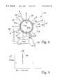
- FIG. 1is a top view of a transmitter pen location system, in which a transmitter pen is located within the writing area of a surface, and in which the transmitter pen periodically sends a combined output signal to external receivers;
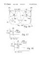
- FIG. 2shows the geometric relationship between a transmitter pen and two external receivers, with the calculated position of the pen is shown as the intersection of arc lengths;
- FIG. 3is a partial top view of external receivers located on a surface
- FIG. 4is a perspective view of an alternate embodiment of the transmitter pen location system, in which a transmitter pen is located within a writing volume, and in which the transmitter pen periodically sends a combined output signal to external receivers;
- FIG. 5is a partial cutaway view of a transmitter pen having a first output signal transducer and a second output signal transducer;
- FIG. 6is a detailed cutaway view of the pointing tip of a transmitter pen having a first output signal transducer and a second output signal transducer;
- FIG. 7is a partial perspective view of the pointing tip of a transmitter pen having a plurality of first output signal transducers and a single second output signal transducer;
- FIG. 8is schematic view of the transmission of first output signal and a second output signal from a transmitter pen
- FIG. 9shows a short pulse waveform of a typical first output signal sent from a transmitter pen
- FIG. 10shows a shaped pulse waveform of one embodiment of a second output signal sent from a transmitter pen
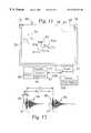
- FIG. 11shows a calculated transcribed path of a transmitter pen from sequential locations, and a defined functional area, within the writing area of a surface
- FIG. 12shows a repeated combined output signal as it is sent from a transmitter pen
- FIG. 13shows a combined output signal as it arrives at a first external receiver
- FIG. 14shows a combined output signal as it arrives at a second external receiver
- FIG. 15is a perspective view showing changes in transmitter pen orientation which can alter the received waveform of the second output signal as it arrives at an external receiver;
- FIG. 16a top view showing the directional reception characteristics of one embodiment of second output sensors at external receivers
- FIG. 17shows a first output signal that includes encoded information which indicates a pen up position
- FIG. 18shows a first output signal that includes encoded information which indicates a pen down position
- FIG. 19shows a first output signal that includes encoded information which indicates a pen up position and supplementary information
- FIG. 20shows a first output signal that includes encoded information which indicates a pen down position and supplementary information
- FIG. 21is an alternate embodiment of the transmitter pen location system, having movable receivers, an automatic-calibration transmitter, and wireless communication between the receivers and the signal processor;
- FIG. 22shows the geometric relationship between a transmitter pen and three external receivers, with the calculated position of the pen shown as the intersection of three arc lengths;
- FIG. 23shows a transmitter pen having a selective function button.
- FIG. 1is a top view of a transmitter pen location system 10 a , in which a transmitter pen 30 located within the writing area 14 of a surface 12 , in which the transmitter pen 30 repeatedly sends a combined output signal 16 to external receivers 18 .
- the surface 12is typically a whiteboard, a blackboard, a drafting table or an overhead projector, or any kind of presentation surface.
- FIG. 2shows the geometric relationship 20 between a transmitter pen 30 and two external receivers 18 a and 18 b , with the calculated (X 1 ,Y 1 ) position of the transmitter pen 30 represented in relation to an X-axis 24 and a Y-axis 26 , as discussed below.
- FIG. 3is a partial top view of external receivers 18 located on a surface 12 .
- the first external receiver 18includes a first output signal sensor 25 and a second output signal sensor 27 a , and includes a signal connection 55 a towards a signal processor 57 (FIG. 11 ).
- the second external receiver 18includes a second output signal sensor 27 b , and also includes a signal connection 55 b to the signal processor 57 .
- FIG. 4is a perspective view of an alternate embodiment of the transmitter pen location system 10 b , in which a transmitter pen 30 is located within a writing volume 14 b , and in which the transmitter pen 30 periodically sends a combined output signal 16 to external receivers 18 a , 18 b , and 18 c .
- the geometric relationship between the transmitter pen 30 and the external receivers 18 a , 18 b and 18 cis repeatedly determined, wherein the successive calculated (X,Y,Z) positions 31 a , 31 b , 31 c of the transmitter pen 30 describe a path 82 , in relation to an X-axis 24 , a Y-axis 26 , and a Z-axis 29 .
- the transmitter pen 30has multiple transducer elements 28 , 44 (FIGS. 5 - 7 ), which are used to determine the location of the pointing tip of the transmitter pen 30 , in relation to a writing area 14 a , or to a writing volume 14 b , of a transmitter pen location system 10 .
- the first output element 44preferably an electromagnetic or infrared transmitter 44 , transmits a first output signal 60 from the transmitter pen 30 to first output signal sensors 25 (FIG. 3) at one or more of the external receivers 18 .
- the first output signal sensors 25are infrared photodiodes, Part No. SFH 205FA, manufactured by Siemens Microelectronics, Inc., of Cupertino, Calif.
- the second output transducer 28transmits a second output signal 58 from the transmitter pen 30 to second output signal sensors 27 at the external receivers 18 .
- the second output signal sensors 27are ultrasound sensors, Part No. AT/R 40-10 P, manufactured by Nippon Ceramic Co. Ltd., of Tottori-Shi, Japan.
- the second output transducer 28 on the transmitter pen 30is an ultrasonic transmitter 28 .
- each receiver 18includes a first output sensor 25
- the first output signal 60which is repeatedly transmitted from the transmitter pen 30 , typically in a periodic manner, arrives at each of the receivers 18 generally concurrently. Since the first output signal 60 arrives at one or more first output sensors 25 generally concurrently, only one first output sensor 25 is typically required, and is typically located at one of the external receivers 18 , or at another external point near the periphery of the writing area 14 .
- a slower second output signal 58which is also repeatedly transmitted from the transmitter pen 30 , typically in a periodic manner, at a known time in relation to the first output signal 60 , arrives at the external receivers 18 at a time which is dependent on the velocity of the second output signal 58 .
- the transmission of the second output signal 58can either be before, after, or concurrent with the transmission of the first output signal 60 , as long as there is a known time between the transmission of the output signals 58 , 60 .
- the velocity of propagation of the first output signals 60 and the second output signals 58are required to be different, so that time span between the arrival of the first output signals 60 and the second output signals 58 at each of the external receivers 18 is dependent on the relative distance between the transmitter pen 30 and each of the external receivers 30 .
- the first output signal 60is an infrared signal 60
- the second output signal 58is an ultrasound signal 58 . In this embodiment, therefore, the propagation velocity of the second output signal 58 is lower than that of the first output signal 60 .
- a combined signal 16comprising a first output signal 60 and a second output signal 58 .
- the combined signal 16is sampled, and is then transferred to a signal processor 57 (FIG. 11 ).
- the location of the pointing tip 36 (FIGS. 5-7) of the transmitter pen 30is then determined by the signal processor 57 , using the first signal 60 as a boundary condition, by solving for calculated distances to each of the receivers 18 using the second output signal 58 , and then by determining a location of the pen based on the calculated distances to the receivers 18 .
- the distance d 1 to the first external receiver 18 ais determined by the relative time of reception of a second output signal 58 and a first output signal 60 within a combined signal pair 16 .
- the distance d 1defines a circular arc 23 a of possible X,Y locations for the transmitter pen 30 .
- the distance d 2 to the second external receiver 18 bis determined by the relative time of reception of the second output signal 58 and the first output signal 60 within the same combined signal pair 16 .
- the distance d 2thus defines a second circular arc 23 b of possible X,Y locations for the transmitter pen 30 , in relation to the second receiver 18 b .
- the (X 1 ,Y 1 ) position of the transmitter pen 30is shown, and is calculated, as the intersection 22 of possible X,Y locations given by the first arc 23 a and the second arc 23 b within the writing area 14 .
- the transmitter pen location processwhich uses the transmitted combined output signal 16 to locate the transmitter pen 30 relative to the writing area 14 of a surface 12 , comprises the following steps:
- the transmitter pen location processthen preferably stores 158 (FIG. 11) the received second output signals 58 b received at each of the receivers 18 , typically replacing the prior second output signals 58 a , whereby the process is repeated for the next received combined output signal 16 .
- precisionis improved further, by storing more than one previous second output signal pulse 58 , and by comparing the incoming second output signal 58 b to a plurality of prior second output signals 58 a.
- FIG. 5is a partial cutaway view of a transmitter pen 30 having a first output signal transducer 44 and a second output signal transducer 28 . While the transmitter pen 30 is described as a pen, it can be any sort of movable transmitter device.
- the transmitter circuitry 40connected to the first output signal transducer through leads 42 a and 42 b , excites the first output signal transducer 44 , to produce a first output signal 60 .
- the transmitter circuitry 40is also connected to the second output signal transducer 28 through leads 46 a and 46 b , and excites the second output signal transducer 28 , to produce a second output signal 58 .
- the second output signal 58 pulse trainhas a periodic frequency of 50 pulses per second.
- FIG. 6is a detailed cutaway view of the pointing tip 36 of a transmitter pen 30 having a first output signal transducer 44 and a second output signal transducer 28 .
- FIG. 7is a partial perspective view of the pointing tip 36 of a transmitter pen 30 having a plurality of first output signal transducers 44 and a single piezoelectric second output signal transducer 28 .
- An optional finger guard 38protects the first output signal transducers 44 and the second output signal transducer 28 .
- FIG. 8is schematic view 50 of the transmission of the combined output signal 16 , which is comprised of a first output signal 60 and a second output signal 58 .
- the first output signal 60is typically an infrared output signal 60 , which is transmitted from one or more infrared transducers 44 located near the pointing tip 36 of the transmitter pen 30 .
- FIG. 9shows a single short pulse waveform 66 of a typical first output signal 60 sent from a transmitter pen 30 .
- the infrared transducers 44are Part No. SFH426, manufactured by Siemens Microelectronics, Inc., of Cupertino, Calif. While only one infrared transducer 44 is required, the use of more than one infrared transducer 44 is preferred, since it allows better line-of-sight transmission of the first output signal 60 to each of the external receivers 18 , such that the transmitter pen 30 can be rotated by the user.
- the second output signal 58is typically an ultrasound output signal 58 , which is transmitted from one or more ultrasound transducers 28 located near the pointing tip 36 of the transmitter pen 30 .
- the ultrasound transducer 28is a cylindrical layered piezoelectric layer 56 surrounded by an outer conductive layer 54 a and an inner conductive layer 54 b , which is connected to the transmitter circuitry 40 by leads 46 a and 46 b and lead connections 52 a and 52 b .
- the ultrasound transducer 28 usedis Part No. AT/R 40-10P, manufactured by Nippon Ceramic Co. Ltd., of Tottori-Shi, Japan.
- FIG. 10shows a first shaped pulse waveform 58 a and a second, subsequent shaped pulse waveform 58 b sent from a transmitter pen 30 .
- an ultrasound second output signal 58can have any waveform shape, including a single ultrasound pulse 72 , it is preferred that the waveform be shaped to have a short duration, with distinctive wave characteristics, which allows the waveform to be measured and compared accurately, to provide an accurate calculated position for the transmitter pen 30 on a frequent basis.
- the subsequent second output signals 58 a , 58 beach include two major pulses 72 a and 72 b , with specific timing between them.
- the short duration output signals 58allow the transmitter pen 30 to send sequential output signals more frequently.
- the use of the short duration ultrasound output signal 58 with distinctive waveform characteristics 72 a , 72 balso allows the transmission of other information to be sent from the transmitter pen 30 to the external receivers 18 , as discussed below. While there are differences between the received amplitude of the subsequent second output signals 58 a and 58 b , each of the signals retain major features, such as waveform characteristics 72 a , 72 b , as well as wavelength dependent features, such as peaks 76 a , 76 b , 76 c , and 76 d . Comparison of these features between subsequent stored digitized output signals 58 a and current output signals 58 b allows the calculated transcribed path 82 of a transmitter pen 30 to be accurately determined, as discussed below.
- FIG. 11is a top view 80 of a calculated transcribed path 82 of a transmitter pen 30 from sequential locations within the writing area 14 of a surface 12 .
- the receivers 18are connected 55 to a signal processor 57 , which calculates successive X-Y locations 84 a , 84 b , . . . 84 n , in relation to a defined X-axis 24 and a Y-axis 26 .
- the successive X-Y locations 84 a , 84 b , . . . 84 n , and the defined path 82can then be stored or transferred by the signal processor 57 .
- a functional area 85is defined in the whiteboard 12 . Selective activation of the transmitter pen 30 within the functional area 85 is used to send function commands to the signal processor 57 , or to a computer 87 connected to the signal processor 57 . Function commands can be used to print the displayed image path 82 , save the image path 82 , create a new page, or to control functions on the connected computer 87 , such as by activating pull-down menus on a graphic-user interface (GUI) 89 on the connected computer 87 .
- GUIgraphic-user interface
- a programmable control application 91 within the computer 87communicates with the signal processor 57 , to control system options, such as waveform comparison algorithms, and the desired number of previous second output signals 58 a to be stored 158 and compared to current second output signals 58 b . Since the prior second output signals 58 a are captured and stored in a digital manner, the comparison between prior second output signals 58 a and current second output signals 58 b can be efficiently monitored or modified through the programmable control application software 91 .
- FIG. 12shows a combined output signal 16 as it is sent from a transmitter pen 30 .
- the combined output signal 16is comprised of a repeated transmission of a first output signal 60 , and a repeated transmission of a second output signal 58 .
- the repeated transmission of the first output signal 60 and the second output signal 58are typically characterized by periods P 1 and P 2 respectively. While the period P 1 of the first output signal 60 and the period P 2 of the second output signal 58 are typically equal, the periods P 1 and P 2 do not have to be the same.
- the infrared output signal 60 and the ultrasound output signal 58are transmitted by the transmitter pen 30 at the same time. In this embodiment, therefore, the ultrasound output signal 58 arrives at each of the external receivers 18 later than the infrared output signal 60 .
- FIG. 13shows the combined output signal 16 as it arrives at a first external receiver 18 a .
- FIG. 14shows the same combined output signal 16 as it arrives at a second, further, external receiver 18 b .
- the distance between the first output signal 60typically comprising one or more infrared pulses 66
- the second output signal 58typically an ultrasound waveform, acts to define the relative time to travel to different external receivers 18 .
- the accuracy of the location of the transmitter pen 30is therefore dependent on the accuracy with which the signal processor 57 connected to the receivers 18 can consistently determine the distance in time between the first output signal 60 and a repeatable reference point 77 (FIG. 10) of the second output ultrasound signal waveform 58 .
- Any repeatable reference point 77 on the second output ultrasound signal waveform 58is sufficient to compare a second output ultrasound signal waveform 58 to stored second output ultrasound signal waveforms 58 a , as long as the repeatable reference point 77 is consistently identified on the current second output ultrasound signal waveform 58 b and on the stored prior second output ultrasound signal waveforms 58 a.
- the crossing time threshold 73indicates a starting point for the repeated ultrasound output signals 58 .
- it is preferred to use a linearly decaying ultrasound threshold 73since the amplitude. of the ultrasound signal 58 falls off like 1/r with distance.
- Nequals the number of receivers 18 (where N ⁇ 2), as shown in FIG. 13 and FIG. 14, the ultrasound signal 58 is received at two or more external receivers 18 .
- the signal processor 57finds a repeatable reference point 77 on the ultrasound output signal 58 a , 58 b , which in one embodiment lies between the threshold crossing 73 and the second peak 76 b .
- a threshold value 75 of 0.5 voltsis used to determine points along the subsequent output signals 58 a , 58 b .
- the first point along the first output signal 58 a to cross the threshold valueis located along the first peak 76 a .
- the first point along the second output signal 58 b to cross the threshold value 75is located along the second peak 76 b . Since subsequent output signals 58 a , 58 b typically have different amplitudes, arbitrary measurement of a threshold 75 to determine a reference point 77 can yield differences between subsequent signal 58 on the order of a wavelength.
- the signal processor 57stores a prior output signal 58 a , and compares repeatable features between the present second output signal 58 b and the stored prior second output signal 58 a .
- Repeatable features that are distinguishabletypically include the shape of major peaks 72 a , 72 b and minor peaks 76 a , 76 b , interpeak spacing, and the relative amplitude of the major peaks 72 a , 72 b and minor peaks 76 a , 76 b.
- the prior output signal 58 aSince the prior output signal 58 a is stored, any or all features can be analyzed and compared, to determine an accurate repeatable reference point 77 . Even the combined relationship between sets of features can be compared.
- the current output signal 58 b and one or more stored prior output signals 58 aare energy-normalized, such that individual peaks 72 , 76 are fit to each other between the current output signal 58 b and the stored prior output signals 58 a .
- the normalized output signalsare then compared for features that do not depend on the amplitude of separate points on the signals 58 a , 58 b , but on the relationship between features.
- the signal processor 57adjusts the actual threshold crossing on peak 76 b on the present output signal 58 b by the period of one wavelength, to establish an adjusted threshold crossing 77 that is consistent with the features of the stored signal 58 a .
- the signal processor 57typically uses the previously received and stored pulse 58 a , from the same receiver 18 , to determine the repeatable reference point 77 on the current ultrasound signal 58 .
- This comparisonis also performed for the present output signal 58 b and the prior output signal 58 a for each of the receivers 18 .
- the output signal 58 ais preferably stored 158 for each receiver location 18 , to provide an accurate comparison for subsequent output signals 58 arriving at each receiver location 18 .
- the current ultrasound signal 58 b for each receiver 18are then stored within memory 158 for analysis of subsequent output signals 58 .
- a plurality of prior signals 58 awith reference points 73 , 77 , can be used to determine repeatable features 77 of the current second output signal 58 a .
- a limited number of previous ultrasound signals 58 a from each receiver 18are typically stored, to conserve memory space within memory 158 .
- N ⁇ 2 second output signals 58 bare then stored within memory 158 as prior second output signals 58 a , for the analysis of subsequent second output signals 58 b.
- Dis the distance between receivers 18 , in units of time taken for the ultrasound signal 58 to travel from one receiver 18 to another receiver 18 .
- Prior analog systemsare inherently limited to “on the fly” comparison between a current signal burst and a small amount of amplitude information from a single prior signal. Since analog systems do not store the entire prior signal bursts in memory, they are limited to the comparison of a small number of features on the last prior signal.
- the transmitter pen location system 10advantageously stores one or more prior signals 58 a , allowing the comparison of a large number of features between the current second output signal 58 b and one or more prior second output signals 58 a.
- FIG. 15is a perspective view showing changes in transmitter pen orientation in relation to external receivers 18 a , 18 b , which can significantly alter the received waveform of the second output signal 58 as it arrives at external receivers 18 .
- the amplitude of the incoming waveform 58can change significantly. from the distance to each of the receivers 18 a , 18 b .
- FIG. 16a top view showing the directional reception characteristics 99 a , 99 b of one embodiment of second output sensors 27 a , 27 b at external receivers 18 a , 18 b .
- the receivers 18 a , 18 bare typically placed at an angle of approximately 45 degrees in relation to a rectangular writing area 14 , to improve signal detection of the second output signal 58 .
- the storage of the received signal 58 to memoryallows signal processing comparison techniques between the current second output signal 58 b and the stored waveform 58 a to be performed, such as by cross-correlation methods.
- An accurate comparison between the features of the present 58 b and prior second output signals 58 acan therefore be made.
- the second output signals 58 barrive at the signal processor 57 , they are preferably normalized to prior stored signals 58 a .
- the received second output signals 58 b and one or more stored second output signals 58 aare normalized to each other, a valid comparison an be made between the normalized output signals 58 a , 58 b .
- the received second output signals 58 b and one or more stored second output signals 58 ahave widely varying signal strengths, it is still possible to cross-correlate features between the normalized paths, rather than to compare the amplitude of a limited number of data points.
- preferred embodiments of the transmitter pen location system 10allow changes to the comparison of features between the current second output signal 58 b and one or more stored prior second output signals 58 a .
- the programmable control application 91(FIG. 11) is typically controllable and updatable, allowing the signal processor 57 to be updated, and to be easily adapted to different transmitter pens 30 , different surfaces 12 , and different receivers 18 .
- the output signal characteristics of the circuitry 40 and characteristic transmitter output signals 58 , 60can optionally communicate secondary information to the external receivers 18 .
- Such supplementary informationcan include pen activation status, or pen types, such as different colored pens, or for pens of different widths, or even for calculated line types, such as for dashed lines.
- the transmitter pens 30can optionally communicate the designated user of each transmitter pen 30 .
- FIG. 17shows a typical first output signal 60 for a transmitter pen 30 in a “pen up” position 68 a .
- the first output signal 60is modified to designate whether the pen is inactivated in a first “pen up” position 68 a , or in an activated second “pen down” position 68 b .
- the output signal 60includes a single infrared pulse 66 a to designate a “pen up” position 68 a .
- the first output signal 60includes two closely space infrared pulses 66 a and 66 b to designate a “pen down” position 68 b , as shown in FIG. 18 .
- the signal processordetermines that the transmitter pen 30 is currently in its “pen up” position 68 a .
- the “pen up” position 68 atypically means that the pointing tip 36 of the transmitter pen 30 is not in contact with either the writing area 14 of the surface 12 , or with another writing surface placed within the writing area 14 , such as a piece of paper.
- the signal processor 57is also able to determine the X-Y coordinate of the transmitter pen 30 while the transmitter pen 30 is in the pen-up position 68 a.
- the signal processor 57determines that the pen 30 is currently in its “pen down” position 68 b , and the X-Y coordinate of the pen 30 is also determined.
- the “pen down” position 68 btypically means that the pen tip 36 is in contact with either the writing area 14 of the surface 12 , or with another writing surface placed within the writing area 14 , such as a piece of paper.
- a series of combined output signals 16are received and processed by the receivers 18 , from which successive X-Y coordinates are determined to produce a representation of the path 82 of the transmitter pen 30 .
- Transmitter pens 30can optionally include circuitry 40 for a given pen “type”, or can include switching or continuous adjustment control to produce a transmitter signal 58 , 60 for different pen attributes.
- a transmitter pen 30which contains a single writing tip 36 having one color of ink, such as black ink, may be selectively adjusted by the user to produce output signals 58 , 60 that correspond to drawn paths 82 of varying colors, widths, or line styles. While the user draws or writes upon a writing surface 14 of a surface 12 , such as a white board 12 , displaying a black path 82 (FIG. 4 , 11 ), such as figures or letters, the transmitted and processed signal for the path 82 is dependent upon the pen characteristics chosen by the user.
- the first input signal 60can optionally provide supplementary information to the receivers 18 .
- FIG. 19shows a first output signal 60 that indicates a pen up position 68 a , using a single pulse 66 a , and encoded supplementary information 66 c - 66 e .
- FIG. 20shows a first output signal that indicates a pen down position 68 b , using a two pulses 66 a , 66 b , and encoded supplementary information 66 c - 66 e .
- the supplementary information 66 c - 66 eprovides bit information, which defines pen characteristics, such as designated color, width, line type, or user identification (e.g. author).
- FIG. 23shows a selective attribute transmitter pen 130 which includes a pen attribute switch 144 .
- the attribute switchis connected to the signal circuitry 40 within the transmitter pen 130 , and controllably alters the transmission of the encoded supplementary information 66 c - 66 e within combined output signals 16 .
- the characteristics or attributes of the transmitter pen 30are thereby selectively activated by the user, through one or more buttons or switches 144 , which control or define the encoded supplementary information 66 c - 66 e.
- the determined color for a transmitter pen 30can either be encoded in the first output signal 60 , such as within multiple infrared pulses 66 a - 66 e , or within the second output signal 58 , such as within distinct waveshapes 72 a , 72 b (FIG. 10 ).
- the time between the pen activation pulses 66 a , 66 b and the secondary information pulses 66 c - 66 ecan span a time that is specific to a particular pen color.
- a first pulse delay between the pen activation pulses 66 a , 66 b and the secondary information pulses 66 c - 66 ecan specify a pen color of black
- a different pulse delay between the pen activation pulses 66 a , 66 b and the secondary information pulses 66 c - 66 ecan specify a pen color of blue.
- a time line 64is broken up into discreet windows 71 a - 71 d , wherein the presence or absence of an infrared pulse 66 c - 66 e indicates a binary “ 0 ” or “ 1 ”, which can be combined with pulses within other windows 71 a - 71 d along the time line 64 , to specify a pen color or type.
- the presence of an infrared signal pulse 66 within a window 71is identified as a bit within a number.
- three windows 71 b - 71 d of 25-50 ms, 50-75 ms, and 75-100 msare used to specify pen color.
- the first window 71 a of 0-25 msis used to start the first output signal 60 , in relation to the second ultrasound signal 58 within a combined signal pair 16 .
- the three-bit numberis chosen to represent pen color or type.
- the binary number for the 25-50 ms window 71 bis a “0”; the binary number for the 50-75 ms window 71 c is a “1”; and the binary number for the 75-100 ms window 71 d is a “1”.
- the same “green” transmitter pen 30is shown in the down position 68 b in FIG. 20 .
- the distance D between receivers 18can either be set once, such as for receivers 18 that are mounted a fixed distance from each other, or can be periodically set, such as for receivers 18 that can be remounted at different positions.
- the distance D between fixed receivers 18can be stored within the signal processor 57 .
- FIG. 21is an alternate embodiment 90 of the transmitter pen location system 10 c , in which the receivers 18 a , 18 b are movable, wherein a calibration transmitter 92 is added at one receiver location 18 b , providing automatic self-calibration for the system 10 b .
- An auto-calibration transmission signal 94is sent from the receiver location 18 b , and is received at another receiver location 18 a .
- the signal processor 57analyzes the incoming auto-calibration transmission signal 94 , and determines the distance D between the receivers 18 a , 18 b .
- FIG. 22is an alternate embodiment 110 of the transmitter pen location system 10 d , which shows the geometric relationship between a transmitter pen 30 and three external receivers 18 a , 18 b , 18 c .
- the calculated position of the pen 30shown as the intersection of three arc lengths 23 a , 23 b and 23 c .
- Small variations in distance D between receivers 18can also be calibrated by the signal processor 57 . This can be useful for many conditions, such as the variation of the speed of sound in different ambient environments (e.g.
- the signal processor 57determines that there is a problem with one or more of the time estimates t i .
- the signal processor 57can also average the known distance D with the calculated distance D between receivers 18 , to adaptively change the value of D.
- transmitter pen location systemand its methods of use are described herein in connection with computer input systems, the techniques can be implemented for other control or display devices, or any combination thereof, as desired.
Landscapes
- Engineering & Computer Science (AREA)
- General Engineering & Computer Science (AREA)
- Theoretical Computer Science (AREA)
- Physics & Mathematics (AREA)
- Human Computer Interaction (AREA)
- General Physics & Mathematics (AREA)
- Acoustics & Sound (AREA)
- Length Measuring Devices Characterised By Use Of Acoustic Means (AREA)
- Measurement Of Velocity Or Position Using Acoustic Or Ultrasonic Waves (AREA)
Abstract
Description


Claims (91)
Priority Applications (6)
| Application Number | Priority Date | Filing Date | Title |
|---|---|---|---|
| US09/165,748US6335723B1 (en) | 1998-10-02 | 1998-10-02 | Transmitter pen location system |
| AU62789/99AAU756022B2 (en) | 1998-10-02 | 1999-10-01 | Transmitter pen location system |
| PCT/US1999/022735WO2000021025A1 (en) | 1998-10-02 | 1999-10-01 | Transmitter pen location system |
| DE69942098TDE69942098D1 (en) | 1998-10-02 | 1999-10-01 | LOCALIZATION SYSTEM OF A TRANSMITTER DEVICE |
| EP99950051AEP1116171B1 (en) | 1998-10-02 | 1999-10-01 | Transmitter pen location system |
| US09/740,630US20010000666A1 (en) | 1998-10-02 | 2000-12-18 | Transmitter pen location system |
Applications Claiming Priority (1)
| Application Number | Priority Date | Filing Date | Title |
|---|---|---|---|
| US09/165,748US6335723B1 (en) | 1998-10-02 | 1998-10-02 | Transmitter pen location system |
Related Child Applications (1)
| Application Number | Title | Priority Date | Filing Date |
|---|---|---|---|
| US09/740,630DivisionUS20010000666A1 (en) | 1998-10-02 | 2000-12-18 | Transmitter pen location system |
Publications (1)
| Publication Number | Publication Date |
|---|---|
| US6335723B1true US6335723B1 (en) | 2002-01-01 |
Family
ID=22600284
Family Applications (2)
| Application Number | Title | Priority Date | Filing Date |
|---|---|---|---|
| US09/165,748Expired - LifetimeUS6335723B1 (en) | 1998-10-02 | 1998-10-02 | Transmitter pen location system |
| US09/740,630AbandonedUS20010000666A1 (en) | 1998-10-02 | 2000-12-18 | Transmitter pen location system |
Family Applications After (1)
| Application Number | Title | Priority Date | Filing Date |
|---|---|---|---|
| US09/740,630AbandonedUS20010000666A1 (en) | 1998-10-02 | 2000-12-18 | Transmitter pen location system |
Country Status (5)
| Country | Link |
|---|---|
| US (2) | US6335723B1 (en) |
| EP (1) | EP1116171B1 (en) |
| AU (1) | AU756022B2 (en) |
| DE (1) | DE69942098D1 (en) |
| WO (1) | WO2000021025A1 (en) |
Cited By (49)
| Publication number | Priority date | Publication date | Assignee | Title |
|---|---|---|---|---|
| US20010020936A1 (en)* | 2000-02-21 | 2001-09-13 | Kenzo Tsuji | Coordinate-capturing apparatus |
| US20020047833A1 (en)* | 2000-10-24 | 2002-04-25 | Takashi Kitada | Position detection system |
| US6414673B1 (en)* | 1998-11-10 | 2002-07-02 | Tidenet, Inc. | Transmitter pen location system |
| WO2002052372A3 (en)* | 2000-12-27 | 2002-09-26 | Firooz Ghassabian | Stylus computer |
| US20020175902A1 (en)* | 2001-04-06 | 2002-11-28 | Koji Hisasue | Transcription system |
| US6654008B2 (en)* | 2000-11-27 | 2003-11-25 | Matsushita Electric Industrial Co., Ltd. | Electronic whiteboard and penholder used for the same |
| US20040010910A1 (en)* | 2002-06-19 | 2004-01-22 | Brian Farrell | Chip package sealing method |
| US20040032399A1 (en)* | 2002-08-15 | 2004-02-19 | Fujitsu Limited | Ultrasonic coordinate input apparatus |
| US6703570B1 (en)* | 2000-05-10 | 2004-03-09 | International Business Machines Corporation | Digital pen using ultrasonic tracking |
| US20040047505A1 (en)* | 2001-12-26 | 2004-03-11 | Firooz Ghassabian | Stylus computer |
| US20040070616A1 (en)* | 2002-06-02 | 2004-04-15 | Hildebrandt Peter W. | Electronic whiteboard |
| US6731270B2 (en)* | 1998-10-21 | 2004-05-04 | Luidia Inc. | Piezoelectric transducer for data entry device |
| US6741237B1 (en)* | 2001-08-23 | 2004-05-25 | Rockwell Automation Technologies, Inc. | Touch screen |
| WO2004010592A3 (en)* | 2002-07-22 | 2004-05-27 | Measurement Spec Inc | Handheld device having ultrasonic transducer for axial transmission of acoustic signals |
| US20040164972A1 (en)* | 2003-02-24 | 2004-08-26 | Carl Stewart R. | Implement for optically inferring information from a planar jotting surface |
| US20040178998A1 (en)* | 2003-03-14 | 2004-09-16 | Sharp Jeffrey L. | Water tolerant touch sensor |
| US20040236311A1 (en)* | 2003-05-23 | 2004-11-25 | Ishii Jerry Seiichi | Medical connector and method for nasally administering or removing a substance |
| US20050093830A1 (en)* | 2003-10-29 | 2005-05-05 | Dan Li | Methods and apparatus to provide a handheld pointer-based user interface |
| US20050110775A1 (en)* | 2003-11-21 | 2005-05-26 | Marc Zuta | Graphic input device and method |
| US20050133700A1 (en)* | 2003-12-22 | 2005-06-23 | Buermann Dale H. | Method and apparatus for determining absolute position of a tip of an elongate object on a plane surface with invariant features |
| US20050168437A1 (en)* | 2004-01-30 | 2005-08-04 | Carl Stewart R. | Processing pose data derived from the pose of an elongate object |
| US20050219204A1 (en)* | 2004-04-05 | 2005-10-06 | Wyatt Huddleston | Interactive display system |
| US20060012579A1 (en)* | 2004-07-14 | 2006-01-19 | Canon Kabushiki Kaisha | Coordinate input apparatus and its control method |
| WO2006057004A1 (en)* | 2004-11-23 | 2006-06-01 | Hewlett-Packard Development Company, L.P. | Systems and methods for estimating distances using multi-resolution functions |
| WO2006131022A1 (en)* | 2005-06-07 | 2006-12-14 | Intel Corporation | Ultrasonic tracking |
| US20070046654A1 (en)* | 2005-08-23 | 2007-03-01 | Nec Viewtechnology, Ltd. | Electronic pen having an ultrasonic wave controller |
| WO2007024460A1 (en) | 2005-08-19 | 2007-03-01 | Cisco Technology, Inc. | Automatic radio site survey using a robot |
| CN100401241C (en)* | 2003-10-10 | 2008-07-09 | Nec显示器解决方案株式会社 | Projectors and Projector Accessories |
| US20080169132A1 (en)* | 2007-01-03 | 2008-07-17 | Yao Ding | Multiple styli annotation system |
| AU2003234093B2 (en)* | 2002-04-15 | 2008-10-23 | Solvay Advanced Polymers, Llc | Polyarylethersulfone compositions exhibiting reduced yellowness and high light transmittance properties and articles made therefrom |
| US20090257315A1 (en)* | 2008-04-10 | 2009-10-15 | Penandfree Co., Ltd. | Position tracing signal generator unit and input system having the same |
| US20090306929A1 (en)* | 2008-06-04 | 2009-12-10 | Mettler-Toledo, Inc. | Ultrasonic dimensioning system and method |
| US20100001998A1 (en)* | 2004-01-30 | 2010-01-07 | Electronic Scripting Products, Inc. | Apparatus and method for determining an absolute pose of a manipulated object in a real three-dimensional environment with invariant features |
| US20100013860A1 (en)* | 2006-03-08 | 2010-01-21 | Electronic Scripting Products, Inc. | Computer interface employing a manipulated object with absolute pose detection component and a display |
| ITMI20082044A1 (en)* | 2008-11-18 | 2010-05-19 | Graf S P A | DEVICE, EQUIPMENT AND SYSTEM FOR THE LOCALIZATION OF OBJECTS OR PERSONS |
| US7746321B2 (en) | 2004-05-28 | 2010-06-29 | Erik Jan Banning | Easily deployable interactive direct-pointing system and presentation control system and calibration method therefor |
| US20100206645A1 (en)* | 2009-02-17 | 2010-08-19 | Jacob Harel | Data Entry Device Utilizing Writing Implement Rotation |
| US8110757B1 (en) | 2004-04-23 | 2012-02-07 | Luidia Inc. | Interference removal in pointing device locating systems |
| US20130106803A1 (en)* | 2010-07-06 | 2013-05-02 | T-Data Systems (S) Pte Ltd | Data storage device with data input function |
| CN103135857A (en)* | 2011-12-05 | 2013-06-05 | 纬创资通股份有限公司 | Portable optical touch system and operation method thereof |
| US20130162953A1 (en)* | 2011-12-23 | 2013-06-27 | Yao Ding | Acoustical Receiver and Pen Transcription System Adapted for Rejecting Virtual Pen Images |
| CN104090661A (en)* | 2014-07-14 | 2014-10-08 | 香港应用科技研究院有限公司 | Portable interactive whiteboard module |
| US9229540B2 (en) | 2004-01-30 | 2016-01-05 | Electronic Scripting Products, Inc. | Deriving input from six degrees of freedom interfaces |
| US20160011721A1 (en)* | 2014-07-14 | 2016-01-14 | Hong Kong Applied Science and Technology Research Institute Company Limited | Portable interactive whiteboard module |
| US9285897B2 (en) | 2005-07-13 | 2016-03-15 | Ultimate Pointer, L.L.C. | Easily deployable interactive direct-pointing system and calibration method therefor |
| US10678322B2 (en) | 2013-11-18 | 2020-06-09 | At&T Intellectual Property I, L.P. | Pressure sensing via bone conduction |
| CN111665967A (en)* | 2015-02-25 | 2020-09-15 | 株式会社和冠 | Method performed in an active pen and active pen |
| US10831316B2 (en) | 2018-07-26 | 2020-11-10 | At&T Intellectual Property I, L.P. | Surface interface |
| US11577159B2 (en) | 2016-05-26 | 2023-02-14 | Electronic Scripting Products Inc. | Realistic virtual/augmented/mixed reality viewing and interactions |
Families Citing this family (52)
| Publication number | Priority date | Publication date | Assignee | Title |
|---|---|---|---|---|
| US20030089783A1 (en)* | 2000-05-03 | 2003-05-15 | Oliver Zechlin | Pen for use with devices comprising a touch-sensitive display device |
| US6717073B2 (en) | 2000-12-29 | 2004-04-06 | Intel Corporation | Wireless display systems, styli, and associated methods |
| US7279646B2 (en)* | 2001-05-25 | 2007-10-09 | Intel Corporation | Digital signature collection and authentication |
| GB0114455D0 (en)* | 2001-06-14 | 2001-08-08 | Koninkl Philips Electronics Nv | Data inut system |
| ITMI20011765A1 (en)* | 2001-08-10 | 2003-02-10 | A & G Soluzioni Digitali S R L | METHOD AND DEVICE TO DETERMINE THE POSITION IN THE THREE-DIMENSION SPACE OF ONE OR MORE INFORMATION POINTERS |
| US7126590B2 (en)* | 2001-10-04 | 2006-10-24 | Intel Corporation | Using RF identification tags in writing instruments as a means for line style differentiation |
| US7489308B2 (en)* | 2003-02-14 | 2009-02-10 | Microsoft Corporation | Determining the location of the tip of an electronic stylus |
| JP4511467B2 (en) | 2003-12-19 | 2010-07-28 | インテル・コーポレーション | Response generation for electronic pen-computer multimedia interactive systems |
| JP4511466B2 (en) | 2003-12-19 | 2010-07-28 | インテル・コーポレーション | Electronic pen-computer multimedia interactive system |
| US20050264545A1 (en)* | 2004-05-27 | 2005-12-01 | Walker Ray A | Method and system for determining the location of a movable icon on a display surface |
| JP4199741B2 (en)* | 2005-02-25 | 2008-12-17 | Necディスプレイソリューションズ株式会社 | Wave receiver and wave reception determination method |
| WO2008107818A1 (en)* | 2007-03-02 | 2008-09-12 | Koninklijke Philips Electronics N.V. | Touch screen and touching-object |
| US8627211B2 (en) | 2007-03-30 | 2014-01-07 | Uranus International Limited | Method, apparatus, system, medium, and signals for supporting pointer display in a multiple-party communication |
| US8060887B2 (en) | 2007-03-30 | 2011-11-15 | Uranus International Limited | Method, apparatus, system, and medium for supporting multiple-party communications |
| US8702505B2 (en) | 2007-03-30 | 2014-04-22 | Uranus International Limited | Method, apparatus, system, medium, and signals for supporting game piece movement in a multiple-party communication |
| US7950046B2 (en)* | 2007-03-30 | 2011-05-24 | Uranus International Limited | Method, apparatus, system, medium, and signals for intercepting a multiple-party communication |
| US7765261B2 (en) | 2007-03-30 | 2010-07-27 | Uranus International Limited | Method, apparatus, system, medium and signals for supporting a multiple-party communication on a plurality of computer servers |
| US7765266B2 (en) | 2007-03-30 | 2010-07-27 | Uranus International Limited | Method, apparatus, system, medium, and signals for publishing content created during a communication |
| EP2140338A4 (en)* | 2007-04-18 | 2016-09-28 | Luidia Inc | Pre-assembled part with an associated surface convertible to a transcription apparatus |
| CN101689355A (en)* | 2007-06-15 | 2010-03-31 | 路迪亚公司 | Interactivity in the massive plate display |
| US8482545B2 (en)* | 2008-10-02 | 2013-07-09 | Wacom Co., Ltd. | Combination touch and transducer input system and method |
| GB2466566B (en) | 2008-12-22 | 2010-12-22 | N trig ltd | Digitizer, stylus and method of synchronization therewith |
| US8120994B2 (en)* | 2009-04-28 | 2012-02-21 | Luidia, Inc. | Digital transcription system utilizing acoustical detectors having apertures with a vertical orientation relative to the work surface |
| EP3470963B1 (en)* | 2009-07-07 | 2021-03-10 | Elliptic Laboratories AS | Control using movements |
| US9019262B2 (en)* | 2009-11-27 | 2015-04-28 | Hologic, Inc. | Systems and methods for tracking positions between imaging modalities and transforming a displayed three-dimensional image corresponding to a position and orientation of a probe |
| US20110248946A1 (en)* | 2010-04-08 | 2011-10-13 | Avaya Inc | Multi-mode prosthetic device to facilitate multi-state touch screen detection |
| SG184582A1 (en)* | 2011-03-07 | 2012-10-30 | Creative Tech Ltd | A method, system and electronic device for association based identification |
| US20140340367A1 (en)* | 2011-09-20 | 2014-11-20 | Kazuya Inoue | Interactive unit attachment structure for projector |
| TWI482100B (en)* | 2011-12-06 | 2015-04-21 | Wistron Corp | Electronic systems and methods for detecting tracks |
| US9250792B2 (en)* | 2012-11-29 | 2016-02-02 | International Business Machines Corporation | Method, apparatus and computer program to designate content retrieval on an interactive display |
| TWI502434B (en)* | 2013-08-02 | 2015-10-01 | Wistron Corp | Touch module and touch positioning method thereof |
| KR102089469B1 (en)* | 2013-09-05 | 2020-03-16 | 현대모비스 주식회사 | Remote Control Apparatus and Method of AVN System |
| CN103813022B (en)* | 2014-03-06 | 2016-03-30 | 联想(北京)有限公司 | A kind of information processing method and electronic equipment |
| CN105807990B (en)* | 2016-03-01 | 2018-11-27 | 京东方科技集团股份有限公司 | Display screen, stylus and display module |
| CN107390958B (en)* | 2017-06-13 | 2020-06-16 | 广州华欣电子科技有限公司 | Intelligent writing method and system |
| DE102017212751A1 (en)* | 2017-07-25 | 2019-01-31 | Robert Bosch Gmbh | Drawing device with a projection unit |
| CN109949622A (en)* | 2017-12-21 | 2019-06-28 | 北京丰信达科技有限公司 | A kind of electronic whiteboard of wisdom blackboard |
| US10466844B1 (en) | 2018-05-21 | 2019-11-05 | UltraSense Systems, Inc. | Ultrasonic touch and force input detection |
| US10719175B2 (en) | 2018-05-21 | 2020-07-21 | UltraSense System, Inc. | Ultrasonic touch sensor and system |
| US20190354238A1 (en) | 2018-05-21 | 2019-11-21 | UltraSense Systems, Inc. | Ultrasonic touch detection and decision |
| US10585534B2 (en) | 2018-05-21 | 2020-03-10 | UltraSense Systems, Inc. | Ultrasonic touch feature extraction |
| US11725993B2 (en) | 2019-12-13 | 2023-08-15 | UltraSense Systems, Inc. | Force-measuring and touch-sensing integrated circuit device |
| US12292351B2 (en) | 2020-01-30 | 2025-05-06 | UltraSense Systems, Inc. | Force-measuring device and related systems |
| US12022737B2 (en) | 2020-01-30 | 2024-06-25 | UltraSense Systems, Inc. | System including piezoelectric capacitor assembly having force-measuring, touch-sensing, and haptic functionalities |
| US11835400B2 (en) | 2020-03-18 | 2023-12-05 | UltraSense Systems, Inc. | Force-measuring device testing system, force-measuring device calibration system, and a method of calibrating a force-measuring device |
| US11719671B2 (en) | 2020-10-26 | 2023-08-08 | UltraSense Systems, Inc. | Methods of distinguishing among touch events |
| US11803274B2 (en) | 2020-11-09 | 2023-10-31 | UltraSense Systems, Inc. | Multi-virtual button finger-touch input systems and methods of detecting a finger-touch event at one of a plurality of virtual buttons |
| US11586290B2 (en) | 2020-12-10 | 2023-02-21 | UltraSense Systems, Inc. | User-input systems and methods of delineating a location of a virtual button by haptic feedback and of determining user-input |
| US12066338B2 (en) | 2021-05-11 | 2024-08-20 | UltraSense Systems, Inc. | Force-measuring device assembly for a portable electronic apparatus, a portable electronic apparatus, and a method of modifying a span of a sense region in a force-measuring device assembly |
| US11681399B2 (en) | 2021-06-30 | 2023-06-20 | UltraSense Systems, Inc. | User-input systems and methods of detecting a user input at a cover member of a user-input system |
| US11481062B1 (en) | 2022-02-14 | 2022-10-25 | UltraSense Systems, Inc. | Solid-state touch-enabled switch and related method |
| US11775073B1 (en) | 2022-07-21 | 2023-10-03 | UltraSense Systems, Inc. | Integrated virtual button module, integrated virtual button system, and method of determining user input and providing user feedback |
Citations (9)
| Publication number | Priority date | Publication date | Assignee | Title |
|---|---|---|---|---|
| US4777329A (en)* | 1987-08-24 | 1988-10-11 | Microfield Graphics, Inc. | Graphic input system |
| US4814552A (en) | 1987-12-02 | 1989-03-21 | Xerox Corporation | Ultrasound position input device |
| EP0312481A2 (en) | 1987-09-16 | 1989-04-19 | José Manuel Ezquerra Perez | Method to determine the position and the state of an object using ultrasonics |
| US4939701A (en) | 1987-08-20 | 1990-07-03 | Wolfgang Brunner | Method and apparatus for error reduction when measuring movement in space of test points by means of ultrasonic signals |
| US5144594A (en) | 1991-05-29 | 1992-09-01 | Cyber Scientific | Acoustic mouse system |
| US5308936A (en)* | 1992-08-26 | 1994-05-03 | Mark S. Knighton | Ultrasonic pen-type data input device |
| WO1994011844A1 (en) | 1992-11-17 | 1994-05-26 | Lectra Systemes | Graphic data acquisition and processing method and device |
| US5729251A (en)* | 1995-02-09 | 1998-03-17 | Fuji Xerox Co., Ltd. | Information input/output system |
| US6151014A (en)* | 1998-02-26 | 2000-11-21 | Pagasus Technologies Ltd. | Systems and processing algorithms for ultrasound time-of-flight digitizer systems |
- 1998
- 1998-10-02USUS09/165,748patent/US6335723B1/ennot_activeExpired - Lifetime
- 1999
- 1999-10-01WOPCT/US1999/022735patent/WO2000021025A1/enactiveIP Right Grant
- 1999-10-01AUAU62789/99Apatent/AU756022B2/ennot_activeCeased
- 1999-10-01DEDE69942098Tpatent/DE69942098D1/ennot_activeExpired - Lifetime
- 1999-10-01EPEP99950051Apatent/EP1116171B1/ennot_activeExpired - Lifetime
- 2000
- 2000-12-18USUS09/740,630patent/US20010000666A1/ennot_activeAbandoned
Patent Citations (10)
| Publication number | Priority date | Publication date | Assignee | Title |
|---|---|---|---|---|
| US4939701A (en) | 1987-08-20 | 1990-07-03 | Wolfgang Brunner | Method and apparatus for error reduction when measuring movement in space of test points by means of ultrasonic signals |
| US4777329A (en)* | 1987-08-24 | 1988-10-11 | Microfield Graphics, Inc. | Graphic input system |
| EP0312481A2 (en) | 1987-09-16 | 1989-04-19 | José Manuel Ezquerra Perez | Method to determine the position and the state of an object using ultrasonics |
| US4814552A (en) | 1987-12-02 | 1989-03-21 | Xerox Corporation | Ultrasound position input device |
| US5144594A (en) | 1991-05-29 | 1992-09-01 | Cyber Scientific | Acoustic mouse system |
| US5308936A (en)* | 1992-08-26 | 1994-05-03 | Mark S. Knighton | Ultrasonic pen-type data input device |
| WO1994011844A1 (en) | 1992-11-17 | 1994-05-26 | Lectra Systemes | Graphic data acquisition and processing method and device |
| US5717168A (en)* | 1992-11-17 | 1998-02-10 | Lectra Systemes | Method and device for capturing and processing graphical information |
| US5729251A (en)* | 1995-02-09 | 1998-03-17 | Fuji Xerox Co., Ltd. | Information input/output system |
| US6151014A (en)* | 1998-02-26 | 2000-11-21 | Pagasus Technologies Ltd. | Systems and processing algorithms for ultrasound time-of-flight digitizer systems |
Cited By (103)
| Publication number | Priority date | Publication date | Assignee | Title |
|---|---|---|---|---|
| US6731270B2 (en)* | 1998-10-21 | 2004-05-04 | Luidia Inc. | Piezoelectric transducer for data entry device |
| US6414673B1 (en)* | 1998-11-10 | 2002-07-02 | Tidenet, Inc. | Transmitter pen location system |
| US7336262B2 (en)* | 2000-02-21 | 2008-02-26 | Oki Data Corporation | Coordinate-capturing apparatus |
| US20010020936A1 (en)* | 2000-02-21 | 2001-09-13 | Kenzo Tsuji | Coordinate-capturing apparatus |
| US6703570B1 (en)* | 2000-05-10 | 2004-03-09 | International Business Machines Corporation | Digital pen using ultrasonic tracking |
| US20020047833A1 (en)* | 2000-10-24 | 2002-04-25 | Takashi Kitada | Position detection system |
| US6798403B2 (en)* | 2000-10-24 | 2004-09-28 | Matsushita Electric Industrial Co., Ltd. | Position detection system |
| US6654008B2 (en)* | 2000-11-27 | 2003-11-25 | Matsushita Electric Industrial Co., Ltd. | Electronic whiteboard and penholder used for the same |
| WO2002052372A3 (en)* | 2000-12-27 | 2002-09-26 | Firooz Ghassabian | Stylus computer |
| US20020175902A1 (en)* | 2001-04-06 | 2002-11-28 | Koji Hisasue | Transcription system |
| US6774891B2 (en)* | 2001-04-06 | 2004-08-10 | Matsushita Electric Industrial Co., Ltd. | Transcription system |
| US6741237B1 (en)* | 2001-08-23 | 2004-05-25 | Rockwell Automation Technologies, Inc. | Touch screen |
| US20040164970A1 (en)* | 2001-08-23 | 2004-08-26 | Benard David J. | Touh screen using echo-location |
| US7079118B2 (en)* | 2001-08-23 | 2006-07-18 | Rockwell Automation Technologies, Inc. | Touch screen using echo-location |
| US20040047505A1 (en)* | 2001-12-26 | 2004-03-11 | Firooz Ghassabian | Stylus computer |
| AU2003234093B2 (en)* | 2002-04-15 | 2008-10-23 | Solvay Advanced Polymers, Llc | Polyarylethersulfone compositions exhibiting reduced yellowness and high light transmittance properties and articles made therefrom |
| US20040070616A1 (en)* | 2002-06-02 | 2004-04-15 | Hildebrandt Peter W. | Electronic whiteboard |
| US20040010910A1 (en)* | 2002-06-19 | 2004-01-22 | Brian Farrell | Chip package sealing method |
| US7218040B2 (en) | 2002-07-22 | 2007-05-15 | Measurement Specialties, Inc. | Handheld device having ultrasonic transducer for axial transmission of acoustic signals |
| WO2004010592A3 (en)* | 2002-07-22 | 2004-05-27 | Measurement Spec Inc | Handheld device having ultrasonic transducer for axial transmission of acoustic signals |
| US7342350B2 (en) | 2002-07-22 | 2008-03-11 | Measurement Specialties, Inc. | Handheld device having ultrasonic transducer for axial transmission of acoustic signals |
| US20040169439A1 (en)* | 2002-07-22 | 2004-09-02 | Minoru Toda | Handheld device having ultrasonic transducer for axial transmission of acoustic signals |
| US20060273696A1 (en)* | 2002-07-22 | 2006-12-07 | Minoru Toda | Handheld device having ultrasonic transducer for axial transmission of acoustic signals |
| US20040032399A1 (en)* | 2002-08-15 | 2004-02-19 | Fujitsu Limited | Ultrasonic coordinate input apparatus |
| US20040164972A1 (en)* | 2003-02-24 | 2004-08-26 | Carl Stewart R. | Implement for optically inferring information from a planar jotting surface |
| US7203384B2 (en) | 2003-02-24 | 2007-04-10 | Electronic Scripting Products, Inc. | Implement for optically inferring information from a planar jotting surface |
| US7116315B2 (en)* | 2003-03-14 | 2006-10-03 | Tyco Electronics Corporation | Water tolerant touch sensor |
| US20040178998A1 (en)* | 2003-03-14 | 2004-09-16 | Sharp Jeffrey L. | Water tolerant touch sensor |
| US20040236311A1 (en)* | 2003-05-23 | 2004-11-25 | Ishii Jerry Seiichi | Medical connector and method for nasally administering or removing a substance |
| CN100401241C (en)* | 2003-10-10 | 2008-07-09 | Nec显示器解决方案株式会社 | Projectors and Projector Accessories |
| US7735024B2 (en) | 2003-10-29 | 2010-06-08 | Intel Corporation | Methods and apparatus to provide a handheld pointer-based user interface |
| US8572514B2 (en) | 2003-10-29 | 2013-10-29 | Intel Corporation | Methods and apparatus to provide a handheld pointer-based user interface |
| US20050093830A1 (en)* | 2003-10-29 | 2005-05-05 | Dan Li | Methods and apparatus to provide a handheld pointer-based user interface |
| US20100097317A1 (en)* | 2003-10-29 | 2010-04-22 | Dan Li | Methods and apparatus to provide a handheld pointer-based user interface |
| US7573467B2 (en)* | 2003-11-21 | 2009-08-11 | Marc Zuta | Graphic input device and method |
| US20050110775A1 (en)* | 2003-11-21 | 2005-05-26 | Marc Zuta | Graphic input device and method |
| US20050133700A1 (en)* | 2003-12-22 | 2005-06-23 | Buermann Dale H. | Method and apparatus for determining absolute position of a tip of an elongate object on a plane surface with invariant features |
| US7088440B2 (en) | 2003-12-22 | 2006-08-08 | Electronic Scripting Products, Inc. | Method and apparatus for determining absolute position of a tip of an elongate object on a plane surface with invariant features |
| US10191559B2 (en) | 2004-01-30 | 2019-01-29 | Electronic Scripting Products, Inc. | Computer interface for manipulated objects with an absolute pose detection component |
| US8542219B2 (en) | 2004-01-30 | 2013-09-24 | Electronic Scripting Products, Inc. | Processing pose data derived from the pose of an elongate object |
| US20050168437A1 (en)* | 2004-01-30 | 2005-08-04 | Carl Stewart R. | Processing pose data derived from the pose of an elongate object |
| US9229540B2 (en) | 2004-01-30 | 2016-01-05 | Electronic Scripting Products, Inc. | Deriving input from six degrees of freedom interfaces |
| US7826641B2 (en) | 2004-01-30 | 2010-11-02 | Electronic Scripting Products, Inc. | Apparatus and method for determining an absolute pose of a manipulated object in a real three-dimensional environment with invariant features |
| US9235934B2 (en) | 2004-01-30 | 2016-01-12 | Electronic Scripting Products, Inc. | Computer interface employing a wearable article with an absolute pose detection component |
| US20100001998A1 (en)* | 2004-01-30 | 2010-01-07 | Electronic Scripting Products, Inc. | Apparatus and method for determining an absolute pose of a manipulated object in a real three-dimensional environment with invariant features |
| US9939911B2 (en) | 2004-01-30 | 2018-04-10 | Electronic Scripting Products, Inc. | Computer interface for remotely controlled objects and wearable articles with absolute pose detection component |
| US20050219204A1 (en)* | 2004-04-05 | 2005-10-06 | Wyatt Huddleston | Interactive display system |
| US8110757B1 (en) | 2004-04-23 | 2012-02-07 | Luidia Inc. | Interference removal in pointing device locating systems |
| US11409376B2 (en) | 2004-05-28 | 2022-08-09 | UltimatePointer, L.L.C. | Multi-sensor device with an accelerometer for enabling user interaction through sound or image |
| US9063586B2 (en) | 2004-05-28 | 2015-06-23 | Ultimatepointer, Llc | Easily deployable interactive direct-pointing system and presentation control system and calibration method therefor |
| US9785255B2 (en) | 2004-05-28 | 2017-10-10 | UltimatePointer, L.L.C. | Apparatus for controlling contents of a computer-generated image using three dimensional measurements |
| US11402927B2 (en) | 2004-05-28 | 2022-08-02 | UltimatePointer, L.L.C. | Pointing device |
| US8049729B2 (en) | 2004-05-28 | 2011-11-01 | Erik Jan Banning | Easily deployable interactive direct-pointing system and presentation control system and calibration method therefor |
| US11416084B2 (en) | 2004-05-28 | 2022-08-16 | UltimatePointer, L.L.C. | Multi-sensor device with an accelerometer for enabling user interaction through sound or image |
| US7746321B2 (en) | 2004-05-28 | 2010-06-29 | Erik Jan Banning | Easily deployable interactive direct-pointing system and presentation control system and calibration method therefor |
| US11073919B2 (en) | 2004-05-28 | 2021-07-27 | UltimatePointer, L.L.C. | Multi-sensor device with an accelerometer for enabling user interaction through sound or image |
| US11755127B2 (en) | 2004-05-28 | 2023-09-12 | UltimatePointer, L.L.C. | Multi-sensor device with an accelerometer for enabling user interaction through sound or image |
| US20100283732A1 (en)* | 2004-05-28 | 2010-11-11 | Erik Jan Banning | Easily deployable interactive direct-pointing system and presentation control system and calibration method therefor |
| US8866742B2 (en) | 2004-05-28 | 2014-10-21 | Ultimatepointer, Llc | Easily deployable interactive direct-pointing system and presentation control system and calibration method therefor |
| US9411437B2 (en) | 2004-05-28 | 2016-08-09 | UltimatePointer, L.L.C. | Easily deployable interactive direct-pointing system and presentation control system and calibration method therefor |
| US20060012579A1 (en)* | 2004-07-14 | 2006-01-19 | Canon Kabushiki Kaisha | Coordinate input apparatus and its control method |
| US7746326B2 (en)* | 2004-07-14 | 2010-06-29 | Canon Kabushiki Kaisha | Coordinate input apparatus and its control method |
| US8195425B2 (en)* | 2004-11-23 | 2012-06-05 | Hewlett-Packard Development Company, L.P. | Systems and methods for estimating distances using multi-resolution functions |
| WO2006057004A1 (en)* | 2004-11-23 | 2006-06-01 | Hewlett-Packard Development Company, L.P. | Systems and methods for estimating distances using multi-resolution functions |
| US20090204364A1 (en)* | 2004-11-23 | 2009-08-13 | Hewlett-Packard Development Company, L.P. | Systems and methods for estimating distances using multi-resolution functions |
| WO2006131022A1 (en)* | 2005-06-07 | 2006-12-14 | Intel Corporation | Ultrasonic tracking |
| US20080128178A1 (en)* | 2005-06-07 | 2008-06-05 | Ying Jia | Ultrasonic Tracking |
| US8614695B2 (en)* | 2005-06-07 | 2013-12-24 | Intel Corporation | Ultrasonic tracking |
| US10372237B2 (en) | 2005-07-13 | 2019-08-06 | UltimatePointer, L.L.C. | Apparatus for controlling contents of a computer-generated image using 3D measurements |
| US9285897B2 (en) | 2005-07-13 | 2016-03-15 | Ultimate Pointer, L.L.C. | Easily deployable interactive direct-pointing system and calibration method therefor |
| US11841997B2 (en) | 2005-07-13 | 2023-12-12 | UltimatePointer, L.L.C. | Apparatus for controlling contents of a computer-generated image using 3D measurements |
| WO2007024460A1 (en) | 2005-08-19 | 2007-03-01 | Cisco Technology, Inc. | Automatic radio site survey using a robot |
| US7842893B2 (en)* | 2005-08-23 | 2010-11-30 | Nec Viewtechnology, Ltd. | Electronic pen having an ultrasonic wave controller |
| US20070046654A1 (en)* | 2005-08-23 | 2007-03-01 | Nec Viewtechnology, Ltd. | Electronic pen having an ultrasonic wave controller |
| US20100013860A1 (en)* | 2006-03-08 | 2010-01-21 | Electronic Scripting Products, Inc. | Computer interface employing a manipulated object with absolute pose detection component and a display |
| US8553935B2 (en) | 2006-03-08 | 2013-10-08 | Electronic Scripting Products, Inc. | Computer interface employing a manipulated object with absolute pose detection component and a display |
| US7961909B2 (en) | 2006-03-08 | 2011-06-14 | Electronic Scripting Products, Inc. | Computer interface employing a manipulated object with absolute pose detection component and a display |
| US20110227915A1 (en)* | 2006-03-08 | 2011-09-22 | Mandella Michael J | Computer interface employing a manipulated object with absolute pose detection component and a display |
| CN101578568B (en)* | 2007-01-03 | 2012-02-08 | 路迪亚公司 | Multiple styli annotation system |
| US20080169132A1 (en)* | 2007-01-03 | 2008-07-17 | Yao Ding | Multiple styli annotation system |
| WO2008086058A1 (en)* | 2007-01-03 | 2008-07-17 | Luidia Inc. | Multiple styli annotation system |
| US20090257315A1 (en)* | 2008-04-10 | 2009-10-15 | Penandfree Co., Ltd. | Position tracing signal generator unit and input system having the same |
| US20090306929A1 (en)* | 2008-06-04 | 2009-12-10 | Mettler-Toledo, Inc. | Ultrasonic dimensioning system and method |
| US20110162456A1 (en)* | 2008-06-04 | 2011-07-07 | Mettler-Toledo, Inc. | Ultrasonic dimensioning system and method |
| ITMI20082044A1 (en)* | 2008-11-18 | 2010-05-19 | Graf S P A | DEVICE, EQUIPMENT AND SYSTEM FOR THE LOCALIZATION OF OBJECTS OR PERSONS |
| US9285899B2 (en)* | 2009-02-17 | 2016-03-15 | Pnf Co., Ltd. | Data entry device utilizing writing implement rotation |
| US20100206645A1 (en)* | 2009-02-17 | 2010-08-19 | Jacob Harel | Data Entry Device Utilizing Writing Implement Rotation |
| US20130106803A1 (en)* | 2010-07-06 | 2013-05-02 | T-Data Systems (S) Pte Ltd | Data storage device with data input function |
| US20130141389A1 (en)* | 2011-12-05 | 2013-06-06 | Chia-Te Chou | Portable optical touch system and operating method thereof |
| CN103135857B (en)* | 2011-12-05 | 2016-05-18 | 纬创资通股份有限公司 | Portable optical touch system and operation method thereof |
| CN103135857A (en)* | 2011-12-05 | 2013-06-05 | 纬创资通股份有限公司 | Portable optical touch system and operation method thereof |
| US8878819B2 (en)* | 2011-12-05 | 2014-11-04 | Wistron Corporation | Portable optical touch system and operating method thereof |
| US20130162953A1 (en)* | 2011-12-23 | 2013-06-27 | Yao Ding | Acoustical Receiver and Pen Transcription System Adapted for Rejecting Virtual Pen Images |
| US8641197B2 (en)* | 2011-12-23 | 2014-02-04 | Luidia Inc. | Acoustical receiver and pen transcription system adapted for rejecting virtual pen images |
| US10678322B2 (en) | 2013-11-18 | 2020-06-09 | At&T Intellectual Property I, L.P. | Pressure sensing via bone conduction |
| CN104090661B (en)* | 2014-07-14 | 2017-06-30 | 香港应用科技研究院有限公司 | Portable interactive whiteboard module |
| CN104090661A (en)* | 2014-07-14 | 2014-10-08 | 香港应用科技研究院有限公司 | Portable interactive whiteboard module |
| US9465486B2 (en)* | 2014-07-14 | 2016-10-11 | Hong Kong Applied Science and Technology Research Institute Company Limited | Portable interactive whiteboard module |
| US20160011721A1 (en)* | 2014-07-14 | 2016-01-14 | Hong Kong Applied Science and Technology Research Institute Company Limited | Portable interactive whiteboard module |
| CN111665967A (en)* | 2015-02-25 | 2020-09-15 | 株式会社和冠 | Method performed in an active pen and active pen |
| CN111665967B (en)* | 2015-02-25 | 2024-04-26 | 株式会社和冠 | Method for executing in active pen and active pen |
| US11577159B2 (en) | 2016-05-26 | 2023-02-14 | Electronic Scripting Products Inc. | Realistic virtual/augmented/mixed reality viewing and interactions |
| US10831316B2 (en) | 2018-07-26 | 2020-11-10 | At&T Intellectual Property I, L.P. | Surface interface |
Also Published As
| Publication number | Publication date |
|---|---|
| AU6278999A (en) | 2000-04-26 |
| AU756022B2 (en) | 2003-01-02 |
| WO2000021025A1 (en) | 2000-04-13 |
| US20010000666A1 (en) | 2001-05-03 |
| EP1116171B1 (en) | 2010-03-03 |
| DE69942098D1 (en) | 2010-04-15 |
| EP1116171A1 (en) | 2001-07-18 |
Similar Documents
| Publication | Publication Date | Title |
|---|---|---|
| US6335723B1 (en) | Transmitter pen location system | |
| US6414673B1 (en) | Transmitter pen location system | |
| US6184873B1 (en) | Pen positioning system | |
| EP0960383B1 (en) | Retrofittable apparatus for converting a substantially planar surface into an electronic data capture device | |
| EP1982253B1 (en) | Touch detection | |
| US6944557B2 (en) | Ultrasonic length measuring apparatus and method for coordinate input | |
| US4991148A (en) | Acoustic digitizing system | |
| US4317005A (en) | Position-determining system | |
| US6724371B1 (en) | Presentation board digitizers | |
| AU7937101A (en) | Transmitter pen location system | |
| JP2009289159A (en) | Handwriting input system | |
| AU718394C (en) | Retrofittable apparatus for converting a substantially planar surface into an electronic data capture device | |
| EP1121662A1 (en) | Triangulation scheme for marking and erasing data entry device | |
| JP2003029917A (en) | Coordinate input device |
Legal Events
| Date | Code | Title | Description |
|---|---|---|---|
| AS | Assignment | Owner name:ELECTRONICS FOR IMAGING, INC., CALIFORNIA Free format text:ASSIGNMENT OF ASSIGNORS INTEREST;ASSIGNORS:WOOD, ROBERT P.;PLOTKIN, SERGE;HAREL, JACOB;AND OTHERS;REEL/FRAME:009502/0981;SIGNING DATES FROM 19980929 TO 19980930 | |
| AS | Assignment | Owner name:TIDENET, IC., CALIFORNIA Free format text:ASSIGNMENT OF ASSIGNORS INTEREST;ASSIGNOR:ELECTRONICS FOR IMAGING, INC.;REEL/FRAME:010869/0925 Effective date:20000621 | |
| STCF | Information on status: patent grant | Free format text:PATENTED CASE | |
| AS | Assignment | Owner name:ELECTRONICS FOR IMAGING, CALIFORNIA Free format text:ASSIGNMENT OF ASSIGNORS INTEREST;ASSIGNOR:TIDENET, INC.;REEL/FRAME:013943/0236 Effective date:20030606 | |
| AS | Assignment | Owner name:LUIDIA, INC., CALIFORNIA Free format text:ASSIGNMENT OF ASSIGNORS INTEREST;ASSIGNOR:ELECTRONICS FOR IMAGING;REEL/FRAME:014043/0270 Effective date:20030702 | |
| FEPP | Fee payment procedure | Free format text:PAT HOLDER CLAIMS SMALL ENTITY STATUS, ENTITY STATUS SET TO SMALL (ORIGINAL EVENT CODE: LTOS); ENTITY STATUS OF PATENT OWNER: SMALL ENTITY | |
| AS | Assignment | Owner name:SILICON VALLEY BANK, CALIFORNIA Free format text:SECURITY INTEREST;ASSIGNOR:LUIDIA, INC;REEL/FRAME:015251/0585 Effective date:20040414 | |
| FPAY | Fee payment | Year of fee payment:4 | |
| AS | Assignment | Owner name:LUIDIA, INC, CALIFORNIA Free format text:RELEASE;ASSIGNOR:SILICON VALLEY BANK;REEL/FRAME:020704/0950 Effective date:20080314 | |
| FPAY | Fee payment | Year of fee payment:8 | |
| AS | Assignment | Owner name:SILICON VALLEY BANK, CALIFORNIA Free format text:SECURITY AGREEMENT;ASSIGNOR:LUIDIA, INC.;REEL/FRAME:026717/0804 Effective date:20110805 | |
| FPAY | Fee payment | Year of fee payment:12 | |
| AS | Assignment | Owner name:LUIDIA, INC., CALIFORNIA Free format text:RELEASE BY SECURED PARTY;ASSIGNOR:SILICON VALLEY BANK;REEL/FRAME:031817/0201 Effective date:20131217 | |
| AS | Assignment | Owner name:ALL QUALITY AND SERVICES, INC., CALIFORNIA Free format text:COURT ORDER;ASSIGNOR:LUIDIA, INC.;REEL/FRAME:036281/0667 Effective date:20150219 | |
| AS | Assignment | Owner name:LUIDIA, INC., CALIFORNIA Free format text:DECLARATION;ASSIGNOR:LUIDIA, INC.;REEL/FRAME:036742/0131 Effective date:20150930 Owner name:LUIDIA, INC., CALIFORNIA Free format text:CORRECTION BY DECLARATION OF INCORRECT NUMBER 6226051 RECORDED AT REEL 036742 FRAME 131;ASSIGNOR:LUIDIA, INC.;REEL/FRAME:036742/0131 Effective date:20150930 | |
| AS | Assignment | Owner name:PNF CO., LTD., CALIFORNIA Free format text:ASSIGNMENT OF ASSIGNORS INTEREST;ASSIGNOR:LUIDIA, INC.;REEL/FRAME:038614/0213 Effective date:20150127 | |
| AS | Assignment | Owner name:PNF CO., LTD., CALIFORNIA Free format text:CORRECTIVE ASSIGNMENT TO CORRECT THE APPLICATION NUMBER 6226051 PREVIOUSLY RECORDED AT REEL: 038614 FRAME: 0213. ASSIGNOR(S) HEREBY CONFIRMS THE ASSIGNMENT;ASSIGNOR:LUIDIA, INC.;REEL/FRAME:044510/0893 Effective date:20150127 |