US6335166B1 - Automated process for isolating and amplifying a target nucleic acid sequence - Google Patents
Automated process for isolating and amplifying a target nucleic acid sequenceDownload PDFInfo
- Publication number
- US6335166B1 US6335166B1US09/303,030US30303099AUS6335166B1US 6335166 B1US6335166 B1US 6335166B1US 30303099 AUS30303099 AUS 30303099AUS 6335166 B1US6335166 B1US 6335166B1
- Authority
- US
- United States
- Prior art keywords
- automated process
- mtu
- receptacle
- reaction receptacle
- station
- Prior art date
- Legal status (The legal status is an assumption and is not a legal conclusion. Google has not performed a legal analysis and makes no representation as to the accuracy of the status listed.)
- Expired - Lifetime
Links
Images


Classifications
- G—PHYSICS
- G01—MEASURING; TESTING
- G01N—INVESTIGATING OR ANALYSING MATERIALS BY DETERMINING THEIR CHEMICAL OR PHYSICAL PROPERTIES
- G01N33/00—Investigating or analysing materials by specific methods not covered by groups G01N1/00 - G01N31/00
- G01N33/48—Biological material, e.g. blood, urine; Haemocytometers
- G01N33/50—Chemical analysis of biological material, e.g. blood, urine; Testing involving biospecific ligand binding methods; Immunological testing
- C—CHEMISTRY; METALLURGY
- C12—BIOCHEMISTRY; BEER; SPIRITS; WINE; VINEGAR; MICROBIOLOGY; ENZYMOLOGY; MUTATION OR GENETIC ENGINEERING
- C12Q—MEASURING OR TESTING PROCESSES INVOLVING ENZYMES, NUCLEIC ACIDS OR MICROORGANISMS; COMPOSITIONS OR TEST PAPERS THEREFOR; PROCESSES OF PREPARING SUCH COMPOSITIONS; CONDITION-RESPONSIVE CONTROL IN MICROBIOLOGICAL OR ENZYMOLOGICAL PROCESSES
- C12Q1/00—Measuring or testing processes involving enzymes, nucleic acids or microorganisms; Compositions therefor; Processes of preparing such compositions
- C12Q1/68—Measuring or testing processes involving enzymes, nucleic acids or microorganisms; Compositions therefor; Processes of preparing such compositions involving nucleic acids
- C12Q1/6813—Hybridisation assays
- C12Q1/6834—Enzymatic or biochemical coupling of nucleic acids to a solid phase
- B—PERFORMING OPERATIONS; TRANSPORTING
- B01—PHYSICAL OR CHEMICAL PROCESSES OR APPARATUS IN GENERAL
- B01F—MIXING, e.g. DISSOLVING, EMULSIFYING OR DISPERSING
- B01F29/00—Mixers with rotating receptacles
- B01F29/10—Mixers with rotating receptacles with receptacles rotated about two different axes, e.g. receptacles having planetary motion
- B—PERFORMING OPERATIONS; TRANSPORTING
- B01—PHYSICAL OR CHEMICAL PROCESSES OR APPARATUS IN GENERAL
- B01F—MIXING, e.g. DISSOLVING, EMULSIFYING OR DISPERSING
- B01F29/00—Mixers with rotating receptacles
- B01F29/30—Mixing the contents of individual packages or containers, e.g. by rotating tins or bottles
- B01F29/32—Containers specially adapted for coupling to rotating frames or the like; Coupling means therefor
- B01F29/322—Containers specially adapted for coupling to rotating frames or the like; Coupling means therefor of two or more containers supported for simultaneous mixing, e.g. for bottles in crates
- B—PERFORMING OPERATIONS; TRANSPORTING
- B01—PHYSICAL OR CHEMICAL PROCESSES OR APPARATUS IN GENERAL
- B01L—CHEMICAL OR PHYSICAL LABORATORY APPARATUS FOR GENERAL USE
- B01L7/00—Heating or cooling apparatus; Heat insulating devices
- B01L7/52—Heating or cooling apparatus; Heat insulating devices with provision for submitting samples to a predetermined sequence of different temperatures, e.g. for treating nucleic acid samples
- B01L7/525—Heating or cooling apparatus; Heat insulating devices with provision for submitting samples to a predetermined sequence of different temperatures, e.g. for treating nucleic acid samples with physical movement of samples between temperature zones
- B01L7/5255—Heating or cooling apparatus; Heat insulating devices with provision for submitting samples to a predetermined sequence of different temperatures, e.g. for treating nucleic acid samples with physical movement of samples between temperature zones by moving sample containers
- B—PERFORMING OPERATIONS; TRANSPORTING
- B03—SEPARATION OF SOLID MATERIALS USING LIQUIDS OR USING PNEUMATIC TABLES OR JIGS; MAGNETIC OR ELECTROSTATIC SEPARATION OF SOLID MATERIALS FROM SOLID MATERIALS OR FLUIDS; SEPARATION BY HIGH-VOLTAGE ELECTRIC FIELDS
- B03C—MAGNETIC OR ELECTROSTATIC SEPARATION OF SOLID MATERIALS FROM SOLID MATERIALS OR FLUIDS; SEPARATION BY HIGH-VOLTAGE ELECTRIC FIELDS
- B03C1/00—Magnetic separation
- B03C1/02—Magnetic separation acting directly on the substance being separated
- B03C1/28—Magnetic plugs and dipsticks
- B03C1/282—Magnetic plugs and dipsticks with associated accumulation indicator, e.g. Hall sensor
- B—PERFORMING OPERATIONS; TRANSPORTING
- B03—SEPARATION OF SOLID MATERIALS USING LIQUIDS OR USING PNEUMATIC TABLES OR JIGS; MAGNETIC OR ELECTROSTATIC SEPARATION OF SOLID MATERIALS FROM SOLID MATERIALS OR FLUIDS; SEPARATION BY HIGH-VOLTAGE ELECTRIC FIELDS
- B03C—MAGNETIC OR ELECTROSTATIC SEPARATION OF SOLID MATERIALS FROM SOLID MATERIALS OR FLUIDS; SEPARATION BY HIGH-VOLTAGE ELECTRIC FIELDS
- B03C1/00—Magnetic separation
- B03C1/02—Magnetic separation acting directly on the substance being separated
- B03C1/28—Magnetic plugs and dipsticks
- B03C1/288—Magnetic plugs and dipsticks disposed at the outer circumference of a recipient
- B—PERFORMING OPERATIONS; TRANSPORTING
- B03—SEPARATION OF SOLID MATERIALS USING LIQUIDS OR USING PNEUMATIC TABLES OR JIGS; MAGNETIC OR ELECTROSTATIC SEPARATION OF SOLID MATERIALS FROM SOLID MATERIALS OR FLUIDS; SEPARATION BY HIGH-VOLTAGE ELECTRIC FIELDS
- B03C—MAGNETIC OR ELECTROSTATIC SEPARATION OF SOLID MATERIALS FROM SOLID MATERIALS OR FLUIDS; SEPARATION BY HIGH-VOLTAGE ELECTRIC FIELDS
- B03C1/00—Magnetic separation
- B03C1/02—Magnetic separation acting directly on the substance being separated
- B03C1/30—Combinations with other devices, not otherwise provided for
- C—CHEMISTRY; METALLURGY
- C12—BIOCHEMISTRY; BEER; SPIRITS; WINE; VINEGAR; MICROBIOLOGY; ENZYMOLOGY; MUTATION OR GENETIC ENGINEERING
- C12Q—MEASURING OR TESTING PROCESSES INVOLVING ENZYMES, NUCLEIC ACIDS OR MICROORGANISMS; COMPOSITIONS OR TEST PAPERS THEREFOR; PROCESSES OF PREPARING SUCH COMPOSITIONS; CONDITION-RESPONSIVE CONTROL IN MICROBIOLOGICAL OR ENZYMOLOGICAL PROCESSES
- C12Q1/00—Measuring or testing processes involving enzymes, nucleic acids or microorganisms; Compositions therefor; Processes of preparing such compositions
- C12Q1/68—Measuring or testing processes involving enzymes, nucleic acids or microorganisms; Compositions therefor; Processes of preparing such compositions involving nucleic acids
- C12Q1/6813—Hybridisation assays
- C12Q1/6832—Enhancement of hybridisation reaction
- G—PHYSICS
- G01—MEASURING; TESTING
- G01N—INVESTIGATING OR ANALYSING MATERIALS BY DETERMINING THEIR CHEMICAL OR PHYSICAL PROPERTIES
- G01N35/00—Automatic analysis not limited to methods or materials provided for in any single one of groups G01N1/00 - G01N33/00; Handling materials therefor
- G01N35/02—Automatic analysis not limited to methods or materials provided for in any single one of groups G01N1/00 - G01N33/00; Handling materials therefor using a plurality of sample containers moved by a conveyor system past one or more treatment or analysis stations
- G01N35/025—Automatic analysis not limited to methods or materials provided for in any single one of groups G01N1/00 - G01N33/00; Handling materials therefor using a plurality of sample containers moved by a conveyor system past one or more treatment or analysis stations having a carousel or turntable for reaction cells or cuvettes
- B—PERFORMING OPERATIONS; TRANSPORTING
- B01—PHYSICAL OR CHEMICAL PROCESSES OR APPARATUS IN GENERAL
- B01F—MIXING, e.g. DISSOLVING, EMULSIFYING OR DISPERSING
- B01F29/00—Mixers with rotating receptacles
- B01F29/40—Parts or components, e.g. receptacles, feeding or discharging means
- B01F29/403—Disposition of the rotor axis
- B01F29/4035—Disposition of the rotor axis with a receptacle rotating around two or more axes
- B01F29/40354—Disposition of the rotor axis with a receptacle rotating around two or more axes arranged for planetary motion
- B—PERFORMING OPERATIONS; TRANSPORTING
- B01—PHYSICAL OR CHEMICAL PROCESSES OR APPARATUS IN GENERAL
- B01L—CHEMICAL OR PHYSICAL LABORATORY APPARATUS FOR GENERAL USE
- B01L2200/00—Solutions for specific problems relating to chemical or physical laboratory apparatus
- B01L2200/14—Process control and prevention of errors
- B01L2200/143—Quality control, feedback systems
- B01L2200/147—Employing temperature sensors
- B—PERFORMING OPERATIONS; TRANSPORTING
- B01—PHYSICAL OR CHEMICAL PROCESSES OR APPARATUS IN GENERAL
- B01L—CHEMICAL OR PHYSICAL LABORATORY APPARATUS FOR GENERAL USE
- B01L2300/00—Additional constructional details
- B01L2300/18—Means for temperature control
- B01L2300/1805—Conductive heating, heat from thermostatted solids is conducted to receptacles, e.g. heating plates, blocks
- B01L2300/1822—Conductive heating, heat from thermostatted solids is conducted to receptacles, e.g. heating plates, blocks using Peltier elements
- B—PERFORMING OPERATIONS; TRANSPORTING
- B01—PHYSICAL OR CHEMICAL PROCESSES OR APPARATUS IN GENERAL
- B01L—CHEMICAL OR PHYSICAL LABORATORY APPARATUS FOR GENERAL USE
- B01L2300/00—Additional constructional details
- B01L2300/18—Means for temperature control
- B01L2300/1805—Conductive heating, heat from thermostatted solids is conducted to receptacles, e.g. heating plates, blocks
- B01L2300/1827—Conductive heating, heat from thermostatted solids is conducted to receptacles, e.g. heating plates, blocks using resistive heater
- B—PERFORMING OPERATIONS; TRANSPORTING
- B01—PHYSICAL OR CHEMICAL PROCESSES OR APPARATUS IN GENERAL
- B01L—CHEMICAL OR PHYSICAL LABORATORY APPARATUS FOR GENERAL USE
- B01L9/00—Supporting devices; Holding devices
- B01L9/06—Test-tube stands; Test-tube holders
- B—PERFORMING OPERATIONS; TRANSPORTING
- B03—SEPARATION OF SOLID MATERIALS USING LIQUIDS OR USING PNEUMATIC TABLES OR JIGS; MAGNETIC OR ELECTROSTATIC SEPARATION OF SOLID MATERIALS FROM SOLID MATERIALS OR FLUIDS; SEPARATION BY HIGH-VOLTAGE ELECTRIC FIELDS
- B03C—MAGNETIC OR ELECTROSTATIC SEPARATION OF SOLID MATERIALS FROM SOLID MATERIALS OR FLUIDS; SEPARATION BY HIGH-VOLTAGE ELECTRIC FIELDS
- B03C2201/00—Details of magnetic or electrostatic separation
- B03C2201/26—Details of magnetic or electrostatic separation for use in medical or biological applications
- C—CHEMISTRY; METALLURGY
- C12—BIOCHEMISTRY; BEER; SPIRITS; WINE; VINEGAR; MICROBIOLOGY; ENZYMOLOGY; MUTATION OR GENETIC ENGINEERING
- C12Q—MEASURING OR TESTING PROCESSES INVOLVING ENZYMES, NUCLEIC ACIDS OR MICROORGANISMS; COMPOSITIONS OR TEST PAPERS THEREFOR; PROCESSES OF PREPARING SUCH COMPOSITIONS; CONDITION-RESPONSIVE CONTROL IN MICROBIOLOGICAL OR ENZYMOLOGICAL PROCESSES
- C12Q2537/00—Reactions characterised by the reaction format or use of a specific feature
- C12Q2537/10—Reactions characterised by the reaction format or use of a specific feature the purpose or use of
- G—PHYSICS
- G01—MEASURING; TESTING
- G01N—INVESTIGATING OR ANALYSING MATERIALS BY DETERMINING THEIR CHEMICAL OR PHYSICAL PROPERTIES
- G01N35/00—Automatic analysis not limited to methods or materials provided for in any single one of groups G01N1/00 - G01N33/00; Handling materials therefor
- G01N2035/00346—Heating or cooling arrangements
- G01N2035/00356—Holding samples at elevated temperature (incubation)
- G—PHYSICS
- G01—MEASURING; TESTING
- G01N—INVESTIGATING OR ANALYSING MATERIALS BY DETERMINING THEIR CHEMICAL OR PHYSICAL PROPERTIES
- G01N35/00—Automatic analysis not limited to methods or materials provided for in any single one of groups G01N1/00 - G01N33/00; Handling materials therefor
- G01N2035/00465—Separating and mixing arrangements
- G01N2035/00524—Mixing by agitating sample carrier
- G—PHYSICS
- G01—MEASURING; TESTING
- G01N—INVESTIGATING OR ANALYSING MATERIALS BY DETERMINING THEIR CHEMICAL OR PHYSICAL PROPERTIES
- G01N35/00—Automatic analysis not limited to methods or materials provided for in any single one of groups G01N1/00 - G01N33/00; Handling materials therefor
- G01N35/02—Automatic analysis not limited to methods or materials provided for in any single one of groups G01N1/00 - G01N33/00; Handling materials therefor using a plurality of sample containers moved by a conveyor system past one or more treatment or analysis stations
- G01N35/04—Details of the conveyor system
- G01N2035/0401—Sample carriers, cuvettes or reaction vessels
- G01N2035/0437—Cleaning cuvettes or reaction vessels
- G—PHYSICS
- G01—MEASURING; TESTING
- G01N—INVESTIGATING OR ANALYSING MATERIALS BY DETERMINING THEIR CHEMICAL OR PHYSICAL PROPERTIES
- G01N35/00—Automatic analysis not limited to methods or materials provided for in any single one of groups G01N1/00 - G01N33/00; Handling materials therefor
- G01N35/02—Automatic analysis not limited to methods or materials provided for in any single one of groups G01N1/00 - G01N33/00; Handling materials therefor using a plurality of sample containers moved by a conveyor system past one or more treatment or analysis stations
- G01N35/04—Details of the conveyor system
- G01N2035/0439—Rotary sample carriers, i.e. carousels
- G01N2035/0453—Multiple carousels working in parallel
- G01N2035/0455—Coaxial carousels
- G—PHYSICS
- G01—MEASURING; TESTING
- G01N—INVESTIGATING OR ANALYSING MATERIALS BY DETERMINING THEIR CHEMICAL OR PHYSICAL PROPERTIES
- G01N35/00—Automatic analysis not limited to methods or materials provided for in any single one of groups G01N1/00 - G01N33/00; Handling materials therefor
- G01N35/10—Devices for transferring samples or any liquids to, in, or from, the analysis apparatus, e.g. suction devices, injection devices
- G01N2035/1027—General features of the devices
- G01N2035/103—General features of the devices using disposable tips
- G—PHYSICS
- G01—MEASURING; TESTING
- G01N—INVESTIGATING OR ANALYSING MATERIALS BY DETERMINING THEIR CHEMICAL OR PHYSICAL PROPERTIES
- G01N35/00—Automatic analysis not limited to methods or materials provided for in any single one of groups G01N1/00 - G01N33/00; Handling materials therefor
- G01N35/0098—Automatic analysis not limited to methods or materials provided for in any single one of groups G01N1/00 - G01N33/00; Handling materials therefor involving analyte bound to insoluble magnetic carrier, e.g. using magnetic separation
- G—PHYSICS
- G01—MEASURING; TESTING
- G01N—INVESTIGATING OR ANALYSING MATERIALS BY DETERMINING THEIR CHEMICAL OR PHYSICAL PROPERTIES
- G01N35/00—Automatic analysis not limited to methods or materials provided for in any single one of groups G01N1/00 - G01N33/00; Handling materials therefor
- G01N35/0099—Automatic analysis not limited to methods or materials provided for in any single one of groups G01N1/00 - G01N33/00; Handling materials therefor comprising robots or similar manipulators
- G—PHYSICS
- G01—MEASURING; TESTING
- G01N—INVESTIGATING OR ANALYSING MATERIALS BY DETERMINING THEIR CHEMICAL OR PHYSICAL PROPERTIES
- G01N35/00—Automatic analysis not limited to methods or materials provided for in any single one of groups G01N1/00 - G01N33/00; Handling materials therefor
- G01N35/10—Devices for transferring samples or any liquids to, in, or from, the analysis apparatus, e.g. suction devices, injection devices
- G01N35/1065—Multiple transfer devices
- Y—GENERAL TAGGING OF NEW TECHNOLOGICAL DEVELOPMENTS; GENERAL TAGGING OF CROSS-SECTIONAL TECHNOLOGIES SPANNING OVER SEVERAL SECTIONS OF THE IPC; TECHNICAL SUBJECTS COVERED BY FORMER USPC CROSS-REFERENCE ART COLLECTIONS [XRACs] AND DIGESTS
- Y10—TECHNICAL SUBJECTS COVERED BY FORMER USPC
- Y10T—TECHNICAL SUBJECTS COVERED BY FORMER US CLASSIFICATION
- Y10T156/00—Adhesive bonding and miscellaneous chemical manufacture
- Y10T156/11—Methods of delaminating, per se; i.e., separating at bonding face
- Y10T156/1105—Delaminating process responsive to feed or shape at delamination
- Y—GENERAL TAGGING OF NEW TECHNOLOGICAL DEVELOPMENTS; GENERAL TAGGING OF CROSS-SECTIONAL TECHNOLOGIES SPANNING OVER SEVERAL SECTIONS OF THE IPC; TECHNICAL SUBJECTS COVERED BY FORMER USPC CROSS-REFERENCE ART COLLECTIONS [XRACs] AND DIGESTS
- Y10—TECHNICAL SUBJECTS COVERED BY FORMER USPC
- Y10T—TECHNICAL SUBJECTS COVERED BY FORMER US CLASSIFICATION
- Y10T156/00—Adhesive bonding and miscellaneous chemical manufacture
- Y10T156/19—Delaminating means
- Y10T156/1906—Delaminating means responsive to feed or shape at delamination
- Y—GENERAL TAGGING OF NEW TECHNOLOGICAL DEVELOPMENTS; GENERAL TAGGING OF CROSS-SECTIONAL TECHNOLOGIES SPANNING OVER SEVERAL SECTIONS OF THE IPC; TECHNICAL SUBJECTS COVERED BY FORMER USPC CROSS-REFERENCE ART COLLECTIONS [XRACs] AND DIGESTS
- Y10—TECHNICAL SUBJECTS COVERED BY FORMER USPC
- Y10T—TECHNICAL SUBJECTS COVERED BY FORMER US CLASSIFICATION
- Y10T29/00—Metal working
- Y10T29/53—Means to assemble or disassemble
- Y10T29/53657—Means to assemble or disassemble to apply or remove a resilient article [e.g., tube, sleeve, etc.]
- Y—GENERAL TAGGING OF NEW TECHNOLOGICAL DEVELOPMENTS; GENERAL TAGGING OF CROSS-SECTIONAL TECHNOLOGIES SPANNING OVER SEVERAL SECTIONS OF THE IPC; TECHNICAL SUBJECTS COVERED BY FORMER USPC CROSS-REFERENCE ART COLLECTIONS [XRACs] AND DIGESTS
- Y10—TECHNICAL SUBJECTS COVERED BY FORMER USPC
- Y10T—TECHNICAL SUBJECTS COVERED BY FORMER US CLASSIFICATION
- Y10T29/00—Metal working
- Y10T29/53—Means to assemble or disassemble
- Y10T29/53683—Spreading parts apart or separating them from face to face engagement
- Y—GENERAL TAGGING OF NEW TECHNOLOGICAL DEVELOPMENTS; GENERAL TAGGING OF CROSS-SECTIONAL TECHNOLOGIES SPANNING OVER SEVERAL SECTIONS OF THE IPC; TECHNICAL SUBJECTS COVERED BY FORMER USPC CROSS-REFERENCE ART COLLECTIONS [XRACs] AND DIGESTS
- Y10—TECHNICAL SUBJECTS COVERED BY FORMER USPC
- Y10T—TECHNICAL SUBJECTS COVERED BY FORMER US CLASSIFICATION
- Y10T29/00—Metal working
- Y10T29/53—Means to assemble or disassemble
- Y10T29/53796—Puller or pusher means, contained force multiplying operator
- Y10T29/53839—Puller or pusher means, contained force multiplying operator having percussion or explosive operator
- Y10T29/53843—Tube, sleeve, or ferrule inserting or removing
- Y—GENERAL TAGGING OF NEW TECHNOLOGICAL DEVELOPMENTS; GENERAL TAGGING OF CROSS-SECTIONAL TECHNOLOGIES SPANNING OVER SEVERAL SECTIONS OF THE IPC; TECHNICAL SUBJECTS COVERED BY FORMER USPC CROSS-REFERENCE ART COLLECTIONS [XRACs] AND DIGESTS
- Y10—TECHNICAL SUBJECTS COVERED BY FORMER USPC
- Y10T—TECHNICAL SUBJECTS COVERED BY FORMER US CLASSIFICATION
- Y10T436/00—Chemistry: analytical and immunological testing
- Y10T436/11—Automated chemical analysis
- Y10T436/111666—Utilizing a centrifuge or compartmented rotor
- Y—GENERAL TAGGING OF NEW TECHNOLOGICAL DEVELOPMENTS; GENERAL TAGGING OF CROSS-SECTIONAL TECHNOLOGIES SPANNING OVER SEVERAL SECTIONS OF THE IPC; TECHNICAL SUBJECTS COVERED BY FORMER USPC CROSS-REFERENCE ART COLLECTIONS [XRACs] AND DIGESTS
- Y10—TECHNICAL SUBJECTS COVERED BY FORMER USPC
- Y10T—TECHNICAL SUBJECTS COVERED BY FORMER US CLASSIFICATION
- Y10T436/00—Chemistry: analytical and immunological testing
- Y10T436/11—Automated chemical analysis
- Y10T436/113332—Automated chemical analysis with conveyance of sample along a test line in a container or rack
- Y10T436/114998—Automated chemical analysis with conveyance of sample along a test line in a container or rack with treatment or replacement of aspirator element [e.g., cleaning, etc.]
- Y—GENERAL TAGGING OF NEW TECHNOLOGICAL DEVELOPMENTS; GENERAL TAGGING OF CROSS-SECTIONAL TECHNOLOGIES SPANNING OVER SEVERAL SECTIONS OF THE IPC; TECHNICAL SUBJECTS COVERED BY FORMER USPC CROSS-REFERENCE ART COLLECTIONS [XRACs] AND DIGESTS
- Y10—TECHNICAL SUBJECTS COVERED BY FORMER USPC
- Y10T—TECHNICAL SUBJECTS COVERED BY FORMER US CLASSIFICATION
- Y10T436/00—Chemistry: analytical and immunological testing
- Y10T436/11—Automated chemical analysis
- Y10T436/119163—Automated chemical analysis with aspirator of claimed structure
- Y—GENERAL TAGGING OF NEW TECHNOLOGICAL DEVELOPMENTS; GENERAL TAGGING OF CROSS-SECTIONAL TECHNOLOGIES SPANNING OVER SEVERAL SECTIONS OF THE IPC; TECHNICAL SUBJECTS COVERED BY FORMER USPC CROSS-REFERENCE ART COLLECTIONS [XRACs] AND DIGESTS
- Y10—TECHNICAL SUBJECTS COVERED BY FORMER USPC
- Y10T—TECHNICAL SUBJECTS COVERED BY FORMER US CLASSIFICATION
- Y10T436/00—Chemistry: analytical and immunological testing
- Y10T436/25—Chemistry: analytical and immunological testing including sample preparation
- Y10T436/2575—Volumetric liquid transfer
Definitions
- the present inventionrelates to an automated analyzer for performing multiple diagnostic assays simultaneously.
- Diagnostic assaysare widely used in clinical diagnosis and health science research to detect or quantify the presence or amount of biological antigens, cell abnormalities, disease states, and disease-associated pathogens, including parasites, fungi, bacteria and viruses present in a host organism or sample. Where a diagnostic assay permits quantification, practitioners may be better able to calculate the extent of infection or disease and to determine the state of a disease over time. In general, diagnostic assays are based either on the detection of antigens (immunoassays) or nucleic acids (nucleic acid-based assays) belonging to an organism or virus of interest.
- Nucleic acid-based assaysgenerally include several leading to the detection or quantification of one or more target nucleic acid sequences can also be specific to the organism or virus of interest.
- the targeted nucleic acid sequencescan also be specific to an identifiable group of organisms or viruses, where the group is defined by at least one shared sequence of nucleic acid that is common to all members of the group and is specified to that group in the sample being assayed.
- the detection of individual and groups of organsisms and viruses using nucleic acid-based methodsis fully described by Kohne, U.S. Pat. No. 4,851,330, and Hogan, U.S. Pat. No. 5,541,308.
- the first step in a nucleic acid-based assayis designing a probe which exhibits specificity, under stringent hybridization conditions, for a nucleic acid sequence belonging to the organism or virus of interest. While nucleic acid-based assays can be designed to detect either deoxyribonucleic acid (DNA) or ribonucleic acid (RNA), ribosomal RNA (rRNA), or the gene encoding rRNA (rDNA), is typically the preferred nucleic acid for detection of a prokaryotic or eukaryotic organism in a sample. Ribosomal RNA target sequences are preferred because of their relative abundance in cells, and because rRNA contains regions of sequence variability that can be exploited to design probes capable of distinguishing between even closely related organisms.
- RNARibosomal RNA is the major structural component of the ribosome, which is the situs of protein synthesis in a cell.
- Viruseswhich do not contain rRNA, and cellular changes are often best detected by targeting DNA, RNA, or a messenger RNA (mRNA) sequence, which is a nucleic acid intermediate used to synthesize a protein.
- mRNAmessenger RNA
- the probesare usually designed to detect identifiable changes in the genetic code, such as the abnormal Philadelphia chromosome associated with chronic myelocytic leukemia. See, e.g.,Stephenson et al., U.S. Pat. No. 4,681,840.
- sample preparationWhen performing a nucleic acid-based assay, preparation of the sample is necessary to release and stabilize target nucleic acids which may be present in the sample. Sample preparation can also serve to eliminate nuclease activity and remove or inactivate potential inhibitors of nucleic acid amplification (discussed below) or detection of the target nucleic acids. See, e.g.,Ryder et al., U.S. Pat. No. 5,639,599, which discloses methods for preparing nucleic acid for amplification, including the use of complexing agents able to complex with ferric ions contributed by lysed red blood cells.
- the method of sample preparationcan vary and will depend in part on the nature of the sample being processed (e.g, blood, urine, stool, pus or sputum).
- a differential lysis procedureis generally followed. See, e.g.,Ryder et al., European Patent Application No. 93304542.9 and European Patent Publication No. 0547267.
- Differential lysis proceduresare well known in the art and are designed to specifically isolate nucleic acids from white blood cells, while limiting or eliminating the presence or activity of red blood cell products, such as heme, which can interfere with nucleic acid amplification or detection.
- the target nucleic acidBefore or after exposing the extracted nucleic acid to a probe, the target nucleic acid can be immobilized by target-capture means, either directly or indirectly, using a “capture probe” bound to a substrate, such as a magnetic bead.
- target-capture methodologiesare described by Ranki et al., U.S. Pat. No. 4,486,539, and Stabinsky, U.S. Pat. No. 4,751,177.
- Target capture probesare generally short sequences of nucleic acid (i.e., oligonucleotide) capable of hybridizing, under stringent hybridization conditions, with a sequence of nucleic acid which also contains the target sequence.
- Magnets in close proximity to the reaction vesselare used to draw and hold the magnetic beads to the side of the vessel.
- the hybridized nucleic acidcan be separated from nonhybridized nucleic acid by aspirating fluid from the reaction vessel and optionally performing one or more wash steps.
- nucleic acid amplificationis the enzymatic synthesis of nucleic acid amplicons (copies) which contain a sequence that is complementary to a nucleic acid sequence being amplified.
- nucleic acid amplification proceduresinclude the polymerase chain reaction (PCR), strand displacement amplification (SDA), ligase chain reaction (LCR), and transcription-associated amplification (TAA).
- PCRpolymerase chain reaction
- SDAstrand displacement amplification
- LCRligase chain reaction
- TAAtranscription-associated amplification
- Nucleic acid amplificationis especially beneficial when the amount of target sequence present in a sample is very low.
- the sensitivity of an assaycan be vastly improved, since fewer target sequences are needed at the beginning of the assay to better ensure detection of nucleic acid in the sample belonging to the organism or virus of interest.
- PCR amplificationfor instance, is described by Mullis et al. in U.S. Pat. Nos. 4,683,195, 4,683,202 and 4,800,159, and in Methods in Enzymology , 155:335-350 (1987). Examples of SDA can be found in Walker, PCR Methods and Applications , 3:25-30 (1993), Walker et al. in Nucleic Acids Res ., 20:1691-1996 (1992) and Proc. Natl. Acad. Sci ., 89:392-396 (1991). LCR is described in U.S. Pat. Nos. 5,427,930 and 5,686,272.
- TAA formatsare provided in publications such as Burg et al. in U.S. Pat. No. 5,437,990; Kacian et al. in U.S. Pat. Nos. 5,399,491 and 5,554,516; and Gingeras et al. in International Application No. PCT/US87/01966 and International Publication No. WO 88/01302, and International Application No. PCT/US88/02108 and International Publication No. WO 88/10315.
- Probesmay include a label capable of detection, where the label is, for example, a radiolabel, fluorescent dye, biotin, enzyme or chemiluminescent compound.
- Chemiluminescent compoundsinclude acridinium esters which can be used in a hybridization protection assay (HPA) and then detected with a luminometer. Examples of chemiluminescent compounds and methods of labeling probes with chemiluminescent compounds can be found in Arnold et al., U.S. Pat. Nos. 4,950,613,5,185,439 and 5,585,481; and Campbell et al., U.S. Pat. No. 4,946,958.
- HPAhybridization protection assay
- HPAis a detection method based on differential hydrolysis which permits specific detection of the acridinium ester-labeled probe hybridized to the target sequence or amplicon thereof.
- HPAis described in detail by Arnold et al. in U.S. Pat. Nos. 5,283,174 and 5,639,604. This detection format permits hybridized probe to be distinguished from non-hybridized probe in solution and includes both a hybridization step and a selection step. In the hybridized step, an excess of acridinium ester-labeled probe is added to the reaction vessel and permitted to anneal to the target sequence or its amplicon.
- label associated with unhybridized probeis rendered non-chemiluminescent in the selection step by the addition of an alkaline reagent.
- the alkaline reagentspecifically hydrolyzes only that acridinium ester label associated with unhybridized probe, leaving the acridinium ester of the probe:target hybrid intact and detectable. Chemiluminescence from the acridinium ester of the hybridized probe can then be measured using a luminometer and signal is expressed in relative light units (RLU).
- RLUrelative light units
- the reaction mixturecan be treated with a deactivating reagent which destroys nucleic acids and related amplification products in the reaction vessel.
- reagentscan include oxidants, reductants and reactive chemicals which modify the primary chemical structure of a nucleic acid. These reagents operate by rendering nucleic acids inert towards an amplification reaction, whether the nucleic acid is RNA or DNA. Examples of such chemical agents include solutions of sodium hypochlorite (bleach), solutions of potassium permanganate, formic acid, hydrazine, dimethyl sulfate and similar compounds. More details of a deactivation protocol can be found in Dattagupta et al., U.S. Pat. No. 5,612,200.
- the complexity and shear number of processing steps associated with a nucleic acidbased assayintroduce opportunities for practitioner-error, exposure to pathogens, and cross-contamination between assays.
- the practitionermust safely and conveniently juxtapose the test samples, reagents, waste containers, assay receptacles, pipette tips, aspirator device, dispenser device, and magnetic rack for performing target-capture, while being especially careful not to confuse racks, test samples, assay receptacles, and associated tips, or to knock over any tubes, tips, containers, or instruments.
- the practitionermust carefully perform aspirating and dispensing steps with handheld, non-fixed instruments in a manner requiring precise execution to avoid undesirable contact between assay receptacles, aerosol formation, or aspiration of magnetic particles or other substrates used in a target-capture assay.
- the magnetic field in a manually performed target-capture assayis often applied to only one side of the assay receptacle so that fluids can be aspirated through a pipette tip inserted along the opposite side of the assay receptacle.
- significant advantagescan be realized by automating the various process steps of a nucleic acid-based assay, including greatly reducing the risk of user-error, pathogen exposure, contamination, and spillage, while significantly increasing through-put volume.
- Automating the steps of a nucleic acid-based assaywill also reduce the amount training required for practitioners and virtually eliminate sources of physical injury attributable to high-volume manual applications.
- the automated clinical analyzerintegrates and coordinates the operation of various automated stations, or modules, involved in performing one or more assays on a plurality of reaction mixtures contained in reaction receptacles.
- the analyzeris preferably a self-contained, stand alone unit.
- Assay specimen materials and reaction receptacles, as well as the various solutions, reagents, and other materials used in performing the assaysare preferably stored within the analyzer, as are the waste products generated when assays are performed.
- the analyzerincludes a computer controller which runs analyzer-controlling and assay-scheduling software to coordinate operation of the stations of the analyzer and movement of each reaction receptacle through the analyzer.
- Reaction receptaclescan be loaded in an input queue which sequentially presents each receptacle at a pickup position to be retrieved by a transport mechanism, which automatically transports the reaction receptacles between the stations of the analyzer.
- Specimen containersare carried on a first ring assembly, and disposable pipette tips are carried on a second ring assembly.
- Containers of target capture reagentincluding a suspension of solid support material, are carried on an inner rotatable assembly constructed and arranged to selectively agitate the containers or present the containers for access by the probe of an automatic robotic pipette system.
- Reaction mixturesincluding fluid specimen material and target capture reagent, are prepared by the pipette system within each reaction receptacle.
- the analyzerfurther includes receptacle mixers for mixing the contents of a receptacle placed therein.
- the mixermay be in fluid communication with fluid containers and may include dispensers for dispensing one or more fluids into the receptacle.
- One or more incubatorscarry multiple receptacles in a temperature-controlled chamber and permit individual receptacles to be automatically placed into and removed from the chamber.
- Magnetic separation wash stationsautomatically perform a magnetic separation wash procedure on the contents of a receptacle placed in the station.
- assay resultsmay be ascertained by the amount of light emitted from a receptacle at the conclusion of the appropriate preparation steps.
- the analyzerincludes a luminometer for detecting and/or quantifying the amount of light emitted by the contents of the reaction receptacle.
- a deactivation queuemay be provided to deactivate the contents of a reaction receptacle placed therein at the conclusion of the assay.
- Reaction receptaclescan be independently transported between stations by the transport mechanism, and the stations can be operated in parallel to perform different assay procedures simultaneously on different reaction receptacles, thereby facilitating efficient, high through-put operation of the analyzer.
- the present inventionfacilitates arranging the various stations associated with a nucleic acid-based assay onto a single, contained platform, thereby achieving efficient space utilization.
- FIG. 1is a perspective view of an automated nucleic acid-based diagnostic analyzer according to the present invention
- FIG. 2is a perspective view of the structural frame of the analyzer of the present invention.
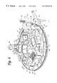
- FIG. 3is a plan view of a portion of the assay processing deck of the analyzer of the present invention.
- FIG. 4is an exploded perspective view of the assay processing deck
- FIG. 5is a plan view of a specimen ring and a pipette tip wheel of the assay processing deck of the analyzer of the present invention
- FIG. 6is a perspective view showing the specimen ring and the pipette tip wheel
- FIG. 6Ais a partial cross-sectional view along the line 6 A— 6 A in FIG. 5;
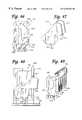
- FIG. 7is a perspective view of a multi-axis mixer of the processing deck of the analyzer of the present invention.
- FIG. 8is a plan view of the multi-axis mixer
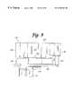
- FIG. 9is a side elevation of the multi-axis mixer
- FIG. 10is a plan view of the multi-axis mixer with container holders and a turntable cover removed therefrom;
- FIG. 11is a cross-sectional view of the multi-axis mixer taken in the direction 11 — 11 in FIG. 10;
- FIG. 12is a perspective view of a drive assembly of the multi-axis mixer
- FIG. 13is a perspective view of a transport mechanism of the processing deck of the analyzer of the present invention.
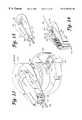
- FIG. 14is a perspective view of a manipulating hook mounting plate and a manipulating hook actuating mechanism of the transport mechanism, with the manipulating hook member engaged with a reaction receptacle and in a retracted position;
- FIG. 15is the same as FIG. 14, except with the manipulating hook member in the extended position;
- FIG. 16is an exploded perspective view of the transport mechanism
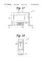
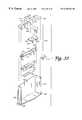
- FIG. 17is a side-elevation of a temperature ramping station of the processing deck of the analyzer of the present invention.
- FIG. 18is a front-elevation of the temperature ramping station
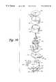
- FIG. 19is a perspective view of a rotary incubator of the processing deck of the analyzer of the present invention.
- FIG. 20is an exploded view of a portion of a housing and access opening closure mechanisms according to a first embodiment of the rotary incubator;
- FIG. 21is a partial view of a skewed disk linear mixer of the rotary incubator, shown engaged with a reaction receptacle employed in a preferred mode of operation of the analyzer of the present invention
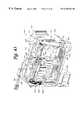
- FIG. 22is an exploded perspective view of the first embodiment of the rotary incubator
- FIG. 23is a perspective view of the rotary incubator according to a second embodiment thereof.
- FIG. 23Ais an exploded perspective view of the second embodiment of the rotary incubator
- FIG. 23Bis a partial exploded perspective view of an access opening closure mechanism of the second embodiment of the rotary incubator
- FIG. 23Cis an exploded view of a receptacle carrier carousel of the second embodiment of the rotary incubator
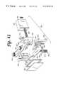
- FIG. 24is a perspective view of a magnetic separation wash station of the processing deck of the present invention with a side plate thereof removed;
- FIG. 25is a partial transverse cross-section of the magnetic separation wash station
- FIG. 25Ais a partial transverse cross-section of a tip of an aspirating tube of the magnetic separation wash station with a contamination-limiting tiplet carried on the end thereof;
- FIG. 26is an exploded perspective view of a receptacle carrier unit, an orbital mixer assembly, and a divider plate of the magnetic separation wash station;
- FIG. 27is a partial cross-sectional view of a wash buffer dispenser nozzle, an aspirator tube with a contamination-limiting tiplet engaged with an end thereof, and a receptacle carrier unit of the magnetic separation wash station, showing a multi-tube unit reaction receptacle employed in a preferred mode of operation of the analyzer carried in the receptacle carrier unit and the aspirator tube and contamination-limiting tiplet inserted into a receptacle vessel of the multitube unit;
- FIG. 28is a partial cross-sectional view of the wash buffer dispenser nozzle, the aspirator tube, and the receptacle carrier unit of the magnetic separation wash station, showing the multi-tube unit carried in if the receptacle carrier unit and the aspirator tube engaging the contamination-limiting tiplet held in a contamination-limiting element holding structure of the multi-tube unit;
- FIGS. 29A-29Dshow a partial cross-section of a first embodiment of a tiplet stripping hole of a tiplet stripping plate of the magnetic separation wash station and a tiplet stripping operation using the tiplet stripping hole;
- FIGS. 30A-30Dshow a partial cross-section of a second embodiment of a tiplet stripping hole and a tiplet stripping operation using the tiplet stripping hole;
- FIG. 31Ais a plan view of a third embodiment of a tiplet stripping hole of a tiplet stripping plate of the magnetic separation wash station;
- FIGS. 31B-31Cshow a partial cross-section of the third embodiment of the tiplet stripping hole and a tiplet stripping operation using the tiplet stripping hole;
- FIG. 32is a perspective view of an orbital mixer with a front plate thereof removed;
- FIG. 33is an exploded view of the orbital mixer of the processing deck of the analyzer of the present invention.
- FIG. 34is a top-plan view of the orbital mixer
- FIG. 35is a top perspective view of a reagent cooling bay of the processing deck of the analyzer of the present invention.
- FIG. 36is a top perspective view of a reagent cooling bay with the container tray removed therefrom;
- FIG. 37is a bottom plan view of the reagent cooling bay
- FIG. 38is an exploded view of the reagent cooling bay
- FIG. 39is a top perspective view of a modular container tray of the reagent cooling bay.
- FIG. 40is a perspective view of a first embodiment of a luminometer of the processing deck of the analyzer of the present invention.
- FIG. 41is a partial exploded perspective view of the luminometer of the first embodiment
- FIG. 42Ais a partial perspective view of a receptacle transport mechanism of the first embodiment of the luminometer
- FIG. 42Bis an end view of the receptacle transport mechanism of the first embodiment of the luminometer
- FIG. 42Cis a top view of the receptacle transport mechanism of the first embodiment of the luminometer
- FIG. 43is a break away perspective view of a second embodiment of the luminometer of the present invention.
- FIG. 44is an exploded perspective view of a multi-tube unit door assembly for the luminometer of the second embodiment
- FIG. 45is an exploded perspective view of a shutter assembly for a photosensor aperture for the luminometer of the second embodiment
- FIG. 45Ais a perspective view of an aperture plate of the shutter assembly of the luminometer of the second embodiment
- FIG. 46is a perspective view of a receptacle vessel positioner assembly of the luminometer of the second embodiment, including a receptacle vessel positioner disposed within a receptacle vessel positioner frame;
- FIG. 47is a perspective view of the receptacle vessel positioner
- FIG. 48is a side elevation of the receptacle vessel positioner assembly
- FIG. 49is a perspective view showing the receptacle vessel positioner of the receptacle vessel positioner assembly operatively engaging a multi-tube unit employed in a preferred mode of operation of the analyzer;
- FIG. 50is a perspective view of a multi-tube unit transport mechanism of the luminometer of the second embodiment
- FIG. 51is a partial perspective view showing a multi-tube unit transport and drive screw of the multi-tube unit transport mechanism of the luminometer;
- FIG. 52is a perspective view of a lower chassis of the analyzer of the present invention.
- FIG. 53is a perspective view of a right-side drawer of the lower chassis
- FIG. 54is a perspective view of a left-side drawer of the lower chassis
- FIG. 55is a perspective view of a specimen tube tray employed in a preferred mode of operation of the analyzer of the present invention.
- FIG. 56is a top plan view of the specimen tube tray
- FIG. 57is a partial cross-section of the specimen tube tray through line “57—57” in FIG. 55;
- FIG. 58is a perspective view of a multi-tube unit employed in a preferred mode of operation of the analyzer of the present invention.
- FIG. 59is a side elevation of a contact-limiting pipette tiplet employed in a preferred mode of operation of the analyzer of the present invention and carried on the multi-tube unit shown in FIG. 58;
- FIG. 60is an enlarged bottom view of a portion of the multi-tube unit, viewed in the direction of arrow “60” in FIG. 58 .
- Analyzer 50includes a housing 60 built over an internal frame structure 62 , preferably made of steel.
- the analyzer 50is preferably supported on caster wheels 64 structurally mounted to the frame structure 62 so as to make the analyzer movable.
- the various stations involved in performing an automated assay and the assay specimensare housed within housing 60 .
- the various solutions, reagents, and other materials used in performing the assaysare preferably stored within the housing 60 , as are the waste products generated when assays are performed with the analyzer 50 .
- Housing 60includes a test receptacle loading opening 68 , which is shown in FIG. 1 to be disposed in a forwardly facing panel of the housing 60 , but could as well be located in other panels of the housing 60 .
- a pipette door 70 having a view window 72 and a carousel door 74 having a view window 76are disposed above a generally horizontal work surface 66 .
- a forwardly protruding arcuate panel 78accommodates a specimen carousel, which will be described below.
- a flip-up arcuate specimen door 80is pivotally attached to the housing so as to be vertically pivotal with respect to arcuate panel 78 so as to provide access to a forward portion of the specimen carousel behind the panel 78 .
- the locking mechanism for each doorpreferably consists of a hook attached to a DC rotary solenoid (rated for continuous duty) with a spring return.
- Preferred rotary solenoidsare available from Lucas Control Systems, of Vandalia, Ohio, model numbers L-2670-034 and L-1094-034.
- An extension portion 102preferably made of a transparent or translucent material, extends above the top portion of housing 60 so as to provide vertical clearance for moving components within the housing 60 .
- the assaysare performed primarily on a processing deck 200 , which is the general location of the various assay stations of the analyzer 50 described below.
- the processing deck 200is shown in FIG. 2 without any of the assay stations mounted thereon.
- the processing deck 200comprises a datum plate 82 to which the various stations are directly or indirectly mounted.
- Datum plate 82preferably comprises a machined aluminum plate.
- the processing deck 200also known as the chemistry deck, separates the interior of the housing into the chemistry area, or upper chassis, above the datum plate 82 and the storage areas, or lower chassis 1100 , located below the datum plate 82 .
- a number of fans and louversare preferably provided in the upper chassis portion of the housing 60 to create air circulation throughout the upper chassis to avoid excessive temperatures in the upper chassis.
- the analyzer 50 of the present inventionis computer controlled
- the analyzer 50includes a computer controller, schematically represented as box 1000 in FIG. 2, which runs highlevel analyzer-controlling software known as the “assay manager program”.
- the assay manager programincludes a scheduler routine which monitors and controls test specimen movement through the chemistry deck 200 .
- the computer controller 1000 which controls the analyzer 50may include a stand-alone computer system including a CPU, keyboard, monitor, and may optionally include a printer device.
- a portable cartmay also be provided for storing and supporting the various computer components.
- the computer hardware for running the analyzer-controlling softwaremay be integrally housed within the housing 60 of the analyzer 50 .
- Low level analyzer controlsuch as control of electric motors and heaters used throughout the analyzer 50 and monitoring of fluid levels within bulk fluid and waste fluid containers, is performed by an embedded controller, preferably comprising a Motorola 68332 microprocessor. Stepper motors used throughout the analyzer are also preferably controlled by preprogrammed, off-the-shelf, microprocessor chips available from E-M Technologies, Bala Cynwyd, Pa.
- FIG. 3represents a schematic plan view of a poriton of the processing deck 200
- FIG. 4represents a schematic perspective view of the processing deck.
- the datum plate 82forms the foundation of the processing deck 200 on which all stations are directly or indirectly attached.
- Processing deck 200includes a reaction receptacle input queue 150 which extends from opening 68 in front of housing 60 .
- a plurality of reaction receptaclesare loaded in a stacked fashion in the input queue 150 .
- the purpose of the input queueis to hold a prescribed number of reaction receptacles and to sequentially present them at a pick-up position to be retrieved by a transport mechanism (described below).
- a reflective sensor at the pick-up positionverifies the presence of a receptacle at that position.
- the input queuealso includes a device for counting the number of receptacles resident therein at any given time.
- a reaction receptacle shuttle assemblywithin the queue moves the receptacles along a receptacle advance path toward the pick-up position.
- Optical sensorsindicate when the shuttle assembly is in its home and fully extended positions.
- the queueincludes a drawer which may be pulled out for loading the receptacles therein. Before the drawer is opened, however, it must be unlocked and the shuttle must disengage from the receptacle advance path. When the drawer is again closed, it is locked and the shuttle engages the receptacles and moves them toward the pick-up position.
- Optical sensorsindicate when the drawer is closed and when the shuttle has engaged a receptacle. As each receptacle is removed from the pick-up position by the transport mechanism, the receptacle shuttle advances the receptacles one receptacle width, so that the next receptacle is in the pick-up position.
- reaction receptaclesare preferably integrally formed linear arrays of test tubes and known as multi-tube units, or MTUs.
- MTUsmulti-tube units
- a first ring assemblywhich in the preferred embodiment comprises a specimen ring 250 , is mounted on a pivoting jig plate 130 at a distance above the datum plate 82 .
- Specimen ring 250is generally circular and preferably holds up to nine specimen trays 300 in an annular fluid container carrier portion thereof, and each of the specimen trays preferably holds 20 specimen-containing containers, or test tubes 320 .
- the specimen ring 250is constructed and arranged to be rotatable about a first generally vertical axis of rotation and delivers the specimen tubes 320 to a specimen pipette assembly 450 , preferably an automated robotic pipette system.
- specimen ring 250is accessible through the flip-up carousel door 80 provided in housing 60 so that trays 300 of test tubes 320 can be easily loaded onto the specimen ring 250 and unloaded from the specimen ring.
- Specimen ring 250is driven by a motor, as will be described in more detail below.
- a second ring assemblywhich in the preferred embodiment comprises a pipette tip wheel 350 , is located in an interior portion of the specimen ring 250 , so that at least a portion of the outer perimeter of the pipette tip wheel 350 is disposed radially inwardly of the inner periphery of the ring 250 .
- Pipette tip wheel 350carries thereon a plurality of commercially available packages of pipette tips.
- Pipette tip wheel 350is motor driven to rotate independently of specimen ring 250 about a second axis of rotation that is generally parallel to the first axis of rotation of the specimen ring 250 .
- the inner rotatable assemblyconstructed and arranged to carry a plurality of fluid containers is provided at an interior portion of the pipette tip wheel 350 .
- the inner rotatable assemblycomprises a multi-axis mixer 400 located radially inside the pipette tip wheel 350 (i.e., the second ring assembly) and specimen ring 250 (i.e., the first ring assembly).
- the multi-axis mixer 400includes a rotating turntable 414 that is rotatable about a third axis of rotation that is generally parallel to the first and second axes of rotation and on which are mounted four independently and eccentrically rotating container holders 406 .
- Each of the container holders 406receives a container, preferably in the form of a plastic bottle, containing a fluid suspension of magnetic particles with immobilized polynucleotides and polynucleotide capture probes.
- Each container holder 406is generally cylindrical in shape and includes an axis of symmetry, or axis of rotation.
- the multi-axis mixer 400rotates each of the containers eccentrically with respect to the center of the holder 406 , while simultaneously rotating the turntable 414 about its center so as to provide substantially constant agitation of the containers to maintain the magnetic particles in suspension within the fluid.
- the specimen pipette assembly, or robot, 450is mounted to the frame structure 62 (see FIG. 2) in a position above the specimen ring 250 and pipette tip wheel 350 .
- the specimen pipette assembly 450includes a pipette unit 456 having a tubular probe 457 mounted on a gantry assembly to provide X, Y, Z motion.
- the pipette unit 456is linearly movable in the Y-direction along a track 458 formed in a lateral rail 454
- the lateral rail 454is longitudinally movable in the X-direction along a longitudinal track 452 .
- the pipette unit 456provides vertical, or Z-axis motion of the probe 457 .
- Drive mechanisms within the specimen pipette assembly 450position the pipette unit 456 to the correct X, Y, Z coordinates within the analyzer 50 to pipette fluids, to wash the probe 457 of the pipette unit 456 , to discard a protective tip from an end of the probe 457 of the pipette unit 456 , or to stow the pipette unit 456 during periods of nonuse, e.g., in a “home” position.
- Each axis of the specimen pipette assembly 450is driven by a stepper motor in a known and conventional manner.
- the pipette assemblyis preferably an off-the-shelf product.
- Presently preferredis the Robotic Sample Processor, model number RSP9000, available from Cavro Inc. of Sunnyvale, Calif. This model includes a single gantry arm.
- the specimen pipette assembly 450is preferably coupled to a syringe pump (not shown) (the Cavro XP 3000 has been used) and a DC driven diaphragm system fluid wash pump (not shown).
- the syringe pump of the specimen pipette assembly 450is preferably mounted to the internal frame structure 62 within the housing 60 of the analyzer 50 at a position above the left-hand side of the chemistry deck 200 and is connected to pipette unit 456 by suitable tubing (not shown) or other conduit structures.
- a specimen preparation opening 252is provided in the jig plate 130 , so that the specimen pipette assembly 450 can access a reaction receptacle 160 in the input queue 150 located below the jig plate 130 .
- the specimen pipette assembly 450 of the analyzer 50engages specimen tubes 320 carried on the specimen ring 250 through openings 140 , 142 of an elevated cover plate 138 and engages pipette tips carried on the pipette tip wheel 350 near the back portions of the specimen ring 250 and pipette tip wheel 350 , respectively. Accordingly, an operator can have access to the forward portions of specimen ring 250 and pipette tip wheel 350 through the carousel door opening 80 during operation of the analyzer without interfering with pipetting procedures.
- a tip wash/disposal station 340is disposed adjacent to the specimen ring 250 on the jig plate 130 .
- Station 340includes a tip disposal tube 342 and a wash station basin 346 .
- the pipette unit 456 of the specimen pipette assembly 450can move into position above the wash station basin 346 where the tubular probe 457 can be washed by pumping distilled water through the probe 457 , the basin of the wash station 346 being connected, preferably by a flexible hose (not shown), to a liquid waste container in the lower chassis 1100 .
- the tip disposal tube 342comprises an upstanding tubular member.
- an elongated pipette tipis frictionally secured onto the end of the tubular probe 457 of the pipette unit 456 , so that specimen material does not come into contact with the tubular probe 457 of the pipette unit 456 when material is drawn from a specimen tube 320 and into the elongated pipette tip.
- the pipette unit 456moves to a position above the tip disposal tube 342 and ejects the used, disposable pipette tip into the tip disposal tube 342 which is connected to one of the solid waste containers carried in the lower chassis 1100 .
- An elongated pipette tipis preferably also frictionally secured to the probe 457 for transferring target capture reagent from containers carried on the multi-axis mixer 400 to a reaction receptacle 160 . Following reagent transfer, the pipette tip is discarded.
- the specimen ring 250 , the pipette tip wheel 350 , and the multi-axis mixer 400are preferably mounted on a hinged jig plate 130 (see FIGS. 5 and 6) supported above the datum plate 82 .
- the jig plate 130is hinged at a back end 132 thereof (see FIG. 6) so that the plate, and the ring 250 , the wheel 350 , and the mixer 400 mounted thereon, can be pivoted upwardly to permit access to the area of the chemistry deck below the jig plate.
- a first, or rightside, transport mechanism 500is mounted on the datum plate 82 below the jig plate 130 and specimen ring 250 on generally the same plane as the input queue 150 .
- Transport mechanism 500includes a rotating main body portion 504 defining a receptacle carrier assembly and an extendible manipulating hook 506 mounted within the main body 504 and extendible and retractable with respect thereto by means of a powered hook member drive assembly.
- Each of the reaction receptacles 160preferably includes manipulating structure that can be engaged by the extendible manipulating hook 506 , so that the transport mechanism 500 can engage and manipulate a reaction receptacle 160 and move it from one location on the processing deck 200 to another as the reaction receptacle is sequentially moved from one station to another during the performance of an assay within the reaction receptacle 160 .
- a second, of left-side, transport mechanism 502of substantially identical construction as first transport mechansim 500 , is also included on the processing deck 200 .
- a plurality of receptacle parking stations 210are also located below the jig plate 130 .
- the parking stations 210are structures for holding specimen-containing reaction receptacles until the assay performing stations of the processing deck 200 of the analyzer 50 are ready to accept the reaction receptacles.
- the reaction receptaclesare retrieved from and inserted into the parking stations 210 as necessary by the transport mechanism 500 .
- a right-side orbital mixer 550is attached to the datum plate 82 and receives reaction receptacles 160 inserted therein by the right-side transport mechanism 500 .
- the orbital mixeris provided to mix the contents of the reaction receptacle 160 .
- the right-side transport mechanism 500removes the reaction receptacle from the right-side orbital mixer 550 and moves it to another location in the processing deck.
- incubators 600 , 602 , 604 , 606of substantially identical construction are provided.
- Incubators 600 , 602 , 604 , and 606are preferably rotary incubators. Although the particular assay to be performed and the desired throughput will determine the desired number of necessary incubators, four incubators are preferably provided in the analyzer 50 .
- each incubator( 600 , 602 , 604 , 606 ) has a first, and may also have a second, receptacle access opening through which a transport mechanism 500 or 502 can insert a reaction receptacle 160 into the incubator or retrieve a reaction receptacle 160 from the incubator.
- a rotating receptacle carrier carouselwhich holds a plurality of reaction receptacles 160 within individual receptacle stations while the receptacles are being incubated.
- first rotary incubator 600is a target capture and annealing incubator
- second rotary incubator 602is an active temperature and preread cool-down incubator (also known as an “AT incubator”)
- third rotary incubator 604is an amplification incubator
- fourth rotary incubator 606is a hybridization protection assay incubator.
- the construction, function, and role of the incubators in the overall performance of the assaywill be described in more detail below.
- the processing deck 200preferably also includes a plurality of temperature ramping stations 700 . Two such stations 700 are shown attached to the datum plate 82 between incubators 602 and 604 in FIG. 3 . Additional ramping stations may be disposed at other locations on the processing deck 200 where they will be accessible by one of the transport mechanisms 500 , 502 .
- a reaction receptacle 160may be placed into or removed from a temperature ramping station 700 by either transport mechanism 500 or 502 .
- Each ramping station 700either raises or lowers the temperature of the reaction receptacle and its contents to a desired temperature before the receptacle is placed into an incubator or another temperature sensitive station.
- the processing deck 200also includes magnetic separation wash stations 800 for performing a magnetic separation wash procedure.
- Each magnetic separation wash station 800can accommodate and perform a wash procedure on one reaction receptacle 160 at a time. Therefore, to achieve the desired throughput, five magnetic separation wash stations 800 working in parallel are preferred.
- Receptacles 160are inserted into and removed from the magnetic separation wash stations 800 by the left-side transport mechanism 502 .
- a reagent cooling bay 900is attached to the datum plate 82 roughly between the incubators 604 and 606 .
- Reagent cooling bay 900comprises a carousel structure having a plurality of container receptacles for holding bottles of temperature sensitive reagents.
- the carouselresides within a cooled housing structure having a lid with pipette access holes formed therein.
- a second, or left-side, orbital mixer 552is disposed between incubators 606 and 604 .
- the left-side orbital mixer 552includes dispenser nozzles and lines for dispensing fluids into the reaction receptacle resident within the left-side orbital mixer 552 .
- a reagent pipette assembly, or robot, 470includes a double gantry structure attached to the frame structure 62 (see FIG. 2) and is disposed generally above the incubators 604 and 606 on the left-hand side of the processing deck 200 .
- reagent pipette assembly 470includes pipette units 480 and 482 .
- Pipette unit 480includes a tubular probe 481 and is mounted for linear movement, generally in the X-direction, along track 474 of lateral rail 476
- pipette unit 482including a tubular probe 483 , is also mounted for linear motion, generally in the X-direction, along track 484 of lateral rail 478 .
- Each pipette unit 480 , 482provides independent vertical, or Z-axis, motion of the respective probe 481 , 483 .
- Drive mechanisms within the assembly 470position the pipette units 480 , 482 to the correct X, Y, Z coordinates within the analyzer 50 to pipette fluids, to wash the tubular probes 481 , 483 of the respective pipette units 480 , 482 , or to stow the pipette units 480 , 482 during periods of nonuse, e.g., in “home” positions.
- Each axis of the pipette assembly 470is driven by a stepper motor.
- the reagent pipette assembly 470is preferably an off-the-shelf product.
- the presently preferred unitis the Cavro Robotic Sample Processor, model RSP9000, with two gantry arms.
- the pipette units 480 , 482 of the reagent pipette assembly 470are each preferably coupled to a respective syringe pump (not shown) (the Cavro XP 3000 has been used) and a DC driven diaphragm system fluid wash pump.
- the syringe pumps of the reagent pipette assembly 470are preferably mounted to the internal frame structure 62 within the housing 60 of the analyzer 50 at a position above the left-hand side of the chemistry deck 200 and are connected to the respective pipette units 480 , 482 by suitable tubing (not shown) or other conduit structures.
- Each pipette unit 480 , 482preferably includes capacitive level sensing capability.
- Capacitive level sensingwhich is generally known in the medical instrumentation arts, employs capacitance changes when the dielectric of a capacitor, formed by the pipette unit as one plate of the capacitor and the structure and hardware surrounding a container engaged by the pipette unit as the opposite plate, changes from air to fluid to sense when the probe of the pipette unit has penetrated fluid within a container.
- the vertical position of the probe of the pipette unitwhich may be known by monitoring the stepper motor which drives vertical movement of the pipette unit, the level of the fluid within the container engaged by the pipette unit may be determined.
- Pipette unit 480transfers reagents from the reagent cooling bay 900 into reaction receptacles disposed within the incubator 606 or the orbital mixer 552
- pipette unit 482transfers reagent materials from the reagent cooling bay 900 into reaction receptacles disposed within the amplification incubator 604 or the orbital mixer 552 .
- the pipette units 480 , 482use capacitive level sensing to ascertain fluid level within a container and submerge only a small portion of the end of the probe of the pipette unit to pipette fluid from the container. Pipette units 480 , 482 preferably descend as fluid is pipetted into the respective tubular probes 481 , 483 to keep the end of the probes submerged to a constant depth.
- the pipette unitsAfter drawing reagent into the tubular probe of the pipette unit 480 or 482 , the pipette units create a minimum travel air gap of 10 ⁇ l in the end of the respective probe 481 or 483 to ensure no drips from the end of the probe as the pipette unit is moved to another location above the chemistry deck 200 .
- the processing deck 200includes a luminometer 950 for detecting and/or quantifying the amount of light emitted by the contents of the reaction receptacle.
- the luminometer 950comprises a housing through which a reaction receptacle travels under the influence of a transport mechanism, a photomultiplier tube, and associated electronics. Various luminometer embodiments will be described in detail below.
- the processing deck 200also preferably includes a deactivation queue 750 .
- the assay performed in the analyzer 50involves the isolation and amplification of nucleic acids belonging to at least one organism or cell of interest. Therefore, it is desirable to deactivate the contents of the reaction receptacle 160 , typically by dispensing a bleach-based reagent into the reaction receptacle 160 at the conclusion of the assay. This deactivation occurs within the deactivation queue 750 .
- reaction receptacle 160Following deactivation, the deactivated contents of the reaction receptacle 160 are stored in one of the liquid waste containers of the lower chassis 1100 and the used reaction receptacle is discarded into a dedicated solid waste container within the lower chassis 1100 .
- the reaction receptacleis preferably not reused.
- the analyzer 50is initially configured for an assay run by loading bulk fluids into the bulk fluid storage bay of the lower chassis 1100 and connecting the bulk fluid containers to the appropriate hoses (not shown).
- the analyzeris preferably powered up in a sequential process, initially powering the stations, or modules, that will be needed early in the process, and subsequently powering the stations that will not be needed until later in the process. This serves to conserve energy and also avoids large power surges that would accompany full analyzer power-up and which could trip circuit breakers.
- the analyzeralso employs a “sleep” mode during periods of nonuse. During sleep mode, a minimal amount of power is supplied to the analyzer, again to avoid large surges necessary to power-up an analyzer from complete shut-down.
- reaction receptacles 160preferably in the form of plastic, integrally formed multipletube units (MTUs), which are described in more detail below, are loaded through opening 68 into the input queue 150 .
- MTUsintegrally formed multipletube units
- the reaction receptacle shuttle assembly (not shown) within the input queue 150moves the MTUs 160 from the loading opening 68 to the pick-up position at the end of the queue 150 .
- the right-side transport mechanism 500takes an MTU 160 from the end of the queue 150 and moves to a bar code reader (not shown) to read the unique bar code label on that MTU which identifies that MTU. From the bar code reader, the MTU is moved to an available specimen transfer station 255 below opening 252 .
- an MTU 160comprises a plurality of individual receptacle vessels 162 , preferably five.
- the receptacle vessels 162preferably in the form of cylindrical tubes with open top ends and closed bottom ends, are connected to one another by a connecting rib structure 164 which defines a downwardly facing shoulder extending longitudinally along either side of the MTU 160 .
- the MTU 160is preferably formed from injection molded polypropylene.
- the most preferred polypropyleneis sold by Montell Polyolefins, of Wilmington, Del., product number PD701NW.
- the Montell materialis used because it is readily moldable, chemically compatible with the preferred mode of operation of the analyzer 50 , and has a limited number of static discharge events which can interfere with accurate detection or quantification of chemiluminescence.
- An arcuate shield structure 169is provided at one end of the MTU 160 .
- An MTU manipulating structure 166 to be engaged by one of the transport mechanisms 500 , 502extends from the shield structure 169 .
- MTU manipulating structure 166comprises a laterally extending plate 168 extending from shield structure 169 with a vertically extending piece 167 on the opposite end of the plate 168 .
- a gusset wall 165extends downwardly from lateral plate 168 between shield structure 169 and vertical piece 167 .
- the shield structure 169 and vertical piece 167have mutually facing convex surfaces.
- the MTU 160is engaged by the transport mechanisms 500 , 502 and other components, as will be described below, by moving an engaging member laterally (in the direction “A”)into the space between the shield structure 169 and the vertical piece 167 .
- the convex surfaces of the shield structure 169 and vertical piece 167provide for wider points of entry for an engaging member undergoing a lateral relative motion into the space.
- the convex surfaces of the vertical piece 167 and shield structure 169include raised portions 171 , 172 , respectively, formed at central portions thereof. The purpose of portions 171 , 172 will be described below.
- a label-receiving structure 174 having a flat label-receiving surface 175is provided on an end of the MTU 160 opposite the shield structure 169 and MTU manipulating structure 166 .
- Labelssuch as scannable bar codes, can be placed on the surface 175 to provide identifying and instructional information on the MTU 160 .
- the MTU 160preferably includes tiplet holding structures 176 adjacent the open mouth of each respective receptacle vessel 162 .
- Each tiplet holding structure 176provides a cylindrical orifice within which is received a contact-limiting tiplet 170 .
- the construction and function of the tiplet 170will be described below.
- Each holding structure 176is constructed and arranged to frictionally receive a tiplet 170 in a manner that prevents the tiplet 170 from falling out of the holding structure 176 when the MTU 160 is inverted, but permits the tiplet 170 to be removed from the holding structure 176 when engaged by a pipette.
- the tiplet 170comprises a generally cylindrical structure having a peripheral rim flange 177 and an upper collar 178 of generally larger diameter than a lower portion 179 of the tiplet 170 .
- the tiplet 170is preferably formed from conductive polypropylene.
- Hole 180includes an outwardly flared end 181 at the top of the tiplet 170 which facilitates insertion of a pipette tubular probe (not shown) into the tiplet 170 .
- Two annular ridges 183line the inner wall of hole 180 . Ridges 183 provide an interference friction fit between the tiplet 170 and a tubular probe inserted into the tiplet 170 .
- the bottom end of the tiplet 170preferably includes a beveled portion 182 .
- a beveled portion 182prevents a vacuum from forming between the end of the tiplet 170 and the bottom of the reaction receptacle vessel.
- the lower chassis 1100includes a steel frame 1101 with a black polyurethane powder coat, a pull-out drip tray 1102 disposed below the chassis, a right-side drawer 1104 , and a left-side drawer 1106 .
- the left-side drawer 1106is actually centrally disposed within the lower chassis 1100 .
- the far left-side of the lower chassis 1100houses various power supply system components and other analyzer mechanisms such as, for example, seven syringe pumps 1152 mounted on a mounting platform 1154 , a vacuum pump 1162 preferably mounted on the floor of the lower chassis 1100 on vibration isolators (not shown), a power supply unit 1156 , a power filter 1158 , and fans 1160 .
- various power supply system components and other analyzer mechanismssuch as, for example, seven syringe pumps 1152 mounted on a mounting platform 1154 , a vacuum pump 1162 preferably mounted on the floor of the lower chassis 1100 on vibration isolators (not shown), a power supply unit 1156 , a power filter 1158 , and fans 1160 .
- a different syringe pump 1152is designated for each of the five magnetic separation wash stations 800 , one is designated for the left-side orbital mixer 552 , and one is designated for the deactivation queue 750 .
- syringe pumpsare preferred, peristaltic pumps may be used as an alternative.
- the vacuum pump 1162services each of the magnetic separation wash stations 800 and the deactivation queue 750 .
- the preferred rating of the vacuum pumpis 5.3-6.5 cfm at 0′′ Hg and 4.2-5.2 cfm at 5′′ Hg.
- a preferred vacuum pumpis available from Thomas Industries, Inc. of Sheboygan, Wis., as model number 2750CGH160.
- a capacitor 1172is sold in conjunction with the pump 1162 .
- the power supply unit 1156is preferably an ASTEC, model number VS1-B5-B7-03, available from ASTEC America, Inc., of Carlsbad, Calif. Power supply unit 1156 accepts 220 volts ranging from 50-60 Hz, i.e.,power from a typical 220 volt wall outlet. Power filter 1158 is preferably a Corcom model 20MV1 filter, available from Corcom, Inc. of Libertyville, Ill. Fans 1160 are preferably Whisper XLDC fans available from Comair Rotron, of San Ysidro, Calif. Each fan is powered by a 24VDC motor and has a 75 cfm output. As shown in FIG.
- the fans 1160are preferably disposed proximate a left-side outer wall of the lower chassis 1100 .
- the fans 1160are preferably directed outwardly to draw air through the lower chassis from the right-side thereof to the left-side thereof, and thus, to draw excess heat out of the lower chassis.
- a power switch 1174preferably an Eaton circuit breaker switch 2-pole, series JA/S, available from the Cutler-Hammer Division of Eaton Corporation of Cleveland, Ohio, and a power inlet module 1176 at which a power cord (not shown) for connecting the analyzer 50 to an external power source is connected.
- a power switch 1174preferably an Eaton circuit breaker switch 2-pole, series JA/S, available from the Cutler-Hammer Division of Eaton Corporation of Cleveland, Ohio
- a power inlet module 1176at which a power cord (not shown) for connecting the analyzer 50 to an external power source is connected.
- the power supply system of the analyzer 50also includes a terminal block (not shown), for attaching thereto a plurality of electrical terminals, a solid state switch (not shown), which is preferably a Crydom Series 1, model number D2425, available from Cal Switch, Carson City, Calif., for switching between different circuits, and an RS232 9-pin connector port for connecting the analyzer 50 to the external computer controller 1000 .
- a terminal blockfor attaching thereto a plurality of electrical terminals
- a solid state switch(not shown), which is preferably a Crydom Series 1, model number D2425, available from Cal Switch, Carson City, Calif., for switching between different circuits
- an RS232 9-pin connector portfor connecting the analyzer 50 to the external computer controller 1000 .
- the right-side drawer and left-side drawer baysare preferably closed behind one or two doors (not shown) in front of the analyzer, which is/are preferably locked by the assay manager program during operation of the analyzer. Microswitches are preferably provided to verify door-closed status.
- the far left bayis covered by a front panel. End panels are provided on opposite ends of the lower chassis to enclose the chassis.
- the leveler feet 1180extend down from the four corners of the chassis 1100 .
- the leveler feet 1180include threaded shafts with pads at the lower ends thereof. When the analyzer is in a desired location, the feet 1180 can be lowered until the pads engage the floor to level and stabilize the analyzer. The feet can also be raised to permit the analyzer to be moved on its casters.
- Bulk fluids typically contained in the containers of the lower chassis 1100may include wash buffer (for washing immobilized target), distilled water (for washing fixed pipette tips), diagnostic testing reagents, silicon oil (used as a floating fluid for layering over test reagents and specimen), and a bleach-based reagent (used for sample deactivation).
- wash bufferfor washing immobilized target
- distilled waterfor washing fixed pipette tips
- diagnostic testing reagentsfor washing fixed pipette tips
- silicon oilused as a floating fluid for layering over test reagents and specimen
- a bleach-based reagentused for sample deactivation
- the right-side drawer 1104is shown in detail in FIG. 53 .
- the right-side drawer 1104includes a boxlike drawer structure with a front drawer handle 1105 .
- drawer handle 1105is shown as a conventional pull-type drawer handle, in the preferred embodiment of the analyzer 50 , handle 1105 is a T-handle latch, such as those available from Southco, Inc. of Concordville, Pa.
- the drawer 1104is mounted in the lower chassis on slide brackets (not shown) so that the drawer 1104 can be pulled into and out of the lower chassis.
- a sensor(not shown) is preferably provided for verifying that the drawer 1104 is closed.
- the front portion of the drawerincludes bottle receptacles 1122 for holding bottle 1128 (shown in FIG. 52 ), which is a dedicated pipette wash waste-containing bottle, and bottle 1130 (also shown in FIG. 52 ), which is a dedicated waste bottle for containing waste from a magnetic wash, target-capture procedure.
- Bottle 1130is preferably evacuated.
- Bottle receptacles 1122preferably include bottle present sensors (not shown) to verify the presence of a bottle in each receptacle 1122 .
- the bottle-present sensorsare preferably diffuse reflective type optical sensors available from SUNX/Ramco Electric, Inc., of West Des Moines, Iowa, model EX-14A.
- Right-side drawer 1104further includes a waste bin 1108 for holding therein spent MTUs and specimen tips.
- Waste bin 1108is an open box structure with a sensor mount 1112 at a top portion thereof for mounting thereon a sensor, preferably a 24VDC Opto-diffuse reflector switch (not shown), for detecting whether the waste bin 1108 is full.
- Another diffuse reflector type optical sensor(not shown) is positioned within right-side drawer 1104 to verify that the waste bin 1108 is in place.
- diffuse reflective type optical sensorsavailable from SUNX/Ramco Electric, Inc., of West Des Moines, Iowa, model EX-14A, are preferred.
- a deflector 1110extends obliquely from a side of the waste bin 1108 .
- Deflector 1110is disposed directly below a chute through which spent MTUs are dropped into the waste bin 1108 and deflects the dropped MTUs toward the middle of the waste bin 1108 to avoid MTU pile-ups in a corner of the waste bin 1108 .
- Deflector 1110is preferably pivotally mounted so that it can pivot upwardly to a substantially vertical position so that when a waste bag, which lines the waste bin 1108 and covers the deflector 1110 , is removed from the waste bin 1108 , the deflector 1110 will pivot upwardly with the bag as it is pulled out and therefore will not rip the bag.
- a printed circuit board (not shown) and cover 1114can be mounted to the front of the waste bin 1108 .
- Sensor mounts 1116 and 1117are also mounted to the front of waste bin 1108 .
- Sensors 1118 and 1119are mounted on sensor mount 1116 , and sensors 1120 and 1121 mounted on sensor mount 1117 .
- Sensors 1118 , 1119 , 1120 , and 1121are preferably DC capacitive proximity sensors.
- the upper sensors 1118 , 1119indicate when the bottles 1128 and 1130 are full, and the bottom sensors 1120 , 1121 indicate when the bottles are empty.
- Sensors 1118 - 1121are preferably those available from Stedham Electronics Corporation of Reno, Nev., model number C2D45AN1-P, which were chosen because their relatively flat physical profile requires less space within the tight confines of the lower chassis 1100 and because the Stedham sensors provide the desired sensing distance range of 3-20 mm.
- the analyzer 50will preferably not begin performing any assays if the assay manager program detects that any of the waste fluid containers in the right-side drawer 1104 are not initially empty.
- the capacitive proximity sensors 1118 - 1121 and the bottle-present, waste-bin-present, and waste-bin-full optical sensors of the right-side drawer 1104are connected to the printed circuit board (not shown) behind cover 1114 , and the printed circuit board is connected to the embedded controller of the analyzer 50 .
- a handle 1126is mounted to the front of the waste bin 1108 and teflon strips 1124 are disposed on the bottom floor of the right-side drawer 1104 to facilitate forward and backward sliding of the waste bin 1108 in the drawer 1104 when bottles 1128 and 1130 are removed.
- Left-side drawer 1106includes a box-like structure with a front mounted handle 1107 and is mounted within the lower chassis 1100 on slide brackets (not shown).
- handle 1107is shown as a conventional pull-type drawer handle, in the preferred embodiment of the analyzer 50 , handle 1107 is a T-handle latch, such as those available from Southco, Inc. of Concordville, Pa.
- a sensoris provided for verifying that the left-side drawer 1106 is closed.
- Left-side drawer 1106includes a tiplet waste bin 1134 with a mounting structure 1135 for mounting thereon a tiplet-waste-bin-full sensor (not shown).
- a tiplet-waste-bin-present sensoris preferably provided in the left-side drawer 1106 to verify that the tiplet waste bin 1134 is properly installed.
- Diffuse reflective type optical sensorsavailable from SUNX/Ramco Electric, Inc., of West Des Moines, Iowa, model EX-14A, are preferred for both the tiplet-waste-bin-full sensor and the tiplet-waste-bin-present sensor.
- Bundling structures 1132are provided for securing and bundling various tubing and/or wires (not shown) within the lower chassis 1100 .
- the bundling structures preferably usedare Energy Chain Systems manufactured and sold by Igus, Inc. of East Buffalo, R.I.
- a printed circuit board 1182is mounted behind a panel 1184 which is located behind the tiplet waste bin 1134 .
- a solenoid valve mounting panel 1186is located below the tiplet waste bin 1134 .
- Left-side drawer 1106includes a forward container-holding structure for holding therein six similarly sized bottles.
- the container structureincludes divider walls 1153 , 1155 , 1157 , and 1159 and container blocks 1151 having a curved bottle-conforming front edge, which together define six container-holding areas.
- Lower sensors 1148 and upper sensors 1150(six of each) are mounted on the divider walls 1155 , 1157 , and 1159 .
- the upper and lower sensors 1148 , 1150are preferably DC capacitive proximity sensors (preferably sensors available from Stedham Electronics Corporation of Reno, Nev., model number C2D45AN1-P, chosen for their flat profile and sensing range).
- the upper sensors 1150indicate when the bottles held in the container structure are full, and the lower sensors 1148 indicate when the bottles are empty.
- the left two bottles 1146contain a detecting agent (“Detect I”)
- the middle two bottles 1168contain silicon oil
- the right two bottles 1170contain another detecting agent (“Detect II”).
- Bottle-present sensorsare preferably provided in each of the container-holding areas defined by the container blocks 1151 and the dividing walls 1153 , 1155 , 1157 , and 1159 to verify the presence of bottles in each container-holding area.
- the bottle-present sensorsare preferably diffuse reflective type optical sensors available from SUNX/Ramco Electric, Inc., of West Des Moines, Iowa, model EX-14A.
- a large centrally located container receptacle 1164holds a bottle 1140 (shown in FIG. 52 ), preferably containing deionized water.
- Container receptacles 1166(only one is visible in FIG. 54) hold bottles 1142 and 1144 (also shown in FIG. 52) preferably containing a wash buffer solution.
- a dividing wall 1143 between the receptacle 1164 and 1166has mounted thereon sensors, such as sensor 1141 , for monitoring the fluid level in the bottles 1140 , 1142 , and 1144 .
- the sensors, such as sensor 1141are preferably DC capacitive proximity sensors (preferably sensors available from Stedham Electronics Corporation of Reno, Nev., model number C2D45AN1-P).
- Container receptacles 1164 and 1166preferably include bottle-present sensors (not shown) for verifying that bottles are properly positioned in their respective receptacles.
- the bottle-present sensorsare preferably diffuse reflective type optical sensors available from SUNX/Ramco Electric, Inc., of West Des Moines, Iowa, model EX-14A.
- the analyzer 50will not begin performing any assays if the assay manager program determines that any of the bulk-fluid containers in the left-side drawer 1106 are initially empty.
- the capacitive proximity fluid level sensors, the various bottle-present sensors, the tiplet-waste-bin-full sensor, and the tiplet-waste-bin-present sensorsare all connected to the printed circuit board 1182 , and the printed circuit board 1182 is connected to the embedded controller of the analyzer 50 .
- solenoid valves(not shown) are mounted below the solenoid valve mounting panel 1186 .
- the solenoid valvesconnect bulk fluid bottles where fluids are stored in pairs of bottles, i.e., the bottles 1140 , 1142 containing wash buffer solution, the two bottles 1146 containing the “Detect I” agent, the two bottles 1168 containing oil, and the two bottles 1170 containing the “Detect II” agent.
- the solenoid valvesin response to signals from the respective capacitive proximity sensors, switch bottles from which fluid is being drawing when one of the two bottles containing the same fluid is empty.
- the solenoid valvesmay switch bottles after a prescribed number of tests are performed.
- the preferred solenoid valvesare teflon solenoid valves available from Beco Manufacturing Co., Inc. of Madison Hills, Calif., model numbers S313W2DFRT and M223W2DFRLT. The two different model numbers correspond to solenoid valves adapted for use with two different tube sizes. Teflon solenoid valves are preferred because they are less likely to contaminate fluids flowing through the valves and the valves are not damaged by corrosive fluids flowing through them.
- Bottle 1136(see FIG. 52) is a vacuum trap held in a vacuum trap bracket 1137 , and bottle 1138 contains a deactivating agent, such as bleach-containing reagent.
- a deactivating agentsuch as bleach-containing reagent.
- bottle-present sensorsare preferably provided to verify the presence of bottles 1136 and 1138 .
- a hand-held bar code scanner 1190may be provided in the lower chassis 1100 for scanning information provided on scannable container labels into the assay manager program.
- Scanner 1190is connected by a cord to printed circuit board 1182 of the left-side drawer 1106 and is preferably stowed on a bracket (not show) mounted on dividing wall 1143 .
- Scannersavailable from Symbol Technologies; Inc., of Holtsville, N.Y. series LS2100, are preferred.
- Specimensare contained in the specimen tubes 320 , and the tubes 320 are loaded into the tube trays 300 outside the analyzer 50 .
- the trays 300 carrying the specimen tubes 320are placed onto the specimen ring 250 through the access opening provided by opening the flip-up carousel door 80 .
- the first ring assembly, or specimen ring, 250is formed of milled, unhardened aluminum and includes a raised ring structure defining an annular trough 251 about the outer periphery of ring 250 with a plurality of raised, radially extending dividers 254 extending through trough 251 .
- nine dividers 254divide the trough 251 into nine arcuate specimen tube tray-receiving wells 256 .
- the trough 251 and wells 256define an annular fluid container carrier portion constructed and arranged to carry a plurality of containers as will be described below.
- Specimen ring 250is preferably rotationally supported by three 120°-spaced V-groove rollers 257 , 258 , 260 which engage a continuous V-ridge 262 formed on the inner periphery of ring 250 , as shown in FIGS. 5, 6 , and 6 A so that the ring 250 is rotatable about a first central axis of rotation.
- the rollersare preferably made by Bishop-Wisecarver Corp. of Pittsburg, Calif., model number W1SSX.
- Rollers 257 and 260are rotationally mounted on fixed shafts, and roller 258 is mounted on a bracket which pivots about a vertical axis and is spring biased so as to urge roller 258 radially outward against the inner periphery of ring 250 .
- ring 250can be easily installed and removed by merely pushing pivoting roller 258 radially inwardly to allow the specimen ring 250 to move laterally to disengage continuous Vridge 262 from the fixed V-groove rollers 257 , 260 .
- Specimen ring 250is driven by stepper motor 264 (VEXTA stepper motors available from Oriental Motor Co., Ltd. of Tokyo, Japan as model number PK266-01A are preferred) via continuous belt 270 (preferably available from SDP/SI of New Hyde Park, N.Y., as model number A6R3M444080) which extends over guide rollers 266 , 268 and around the outer periphery of ring 250 .
- a home sensor and a sector sensor(not shown), preferably slotted optical sensors, are provided adjacent the ring 250 at a rotational home position and at a position corresponding to one of the specimen tube tray receiving wells 256 .
- the ring 250includes a home flag (not shown) located at a home position on the wheel and nine equally-spaced sector flags (not shown) corresponding to the positions of each of the nine specimen tube tray receiving wells 256 .
- the home flag and sector flagscooperate with the home sensor and sector sensors to provide ring position information to the assay manager program and to control the ring 250 to stop at nine discrete positions corresponding to established coordinates for user re-load and access by pipette unit 450 .
- Preferred sensors for the home sensor and sector sensorare Optek slotted optical sensors, model number OPB857, available from Optek of Carrollton, Tex.
- a specimen coveris disposed over a portion of the annular fluid container carrier portion, or trough 251 , and comprises an arcuate cover plate 138 fixed in an elevated position with respect to the wheel 250 on three mounting posts 136 .
- Plate 138has an arcuate shape generally conforming to the curve of the trough 251 .
- a first opening 142is formed in the plate 138
- a second opening 140is formed in the plate 138 at a greater radial distance from the axis of rotation of ring 250 than opening 142 and at a circumferentially-spaced position from opening 142 .
- each specimen tube tray 300comprises a test tube rack structure that is curved to conform to the curvature of the ring 250 .
- Each tray 300comprises a central wall structure 304 with lateral end walls 303 and 305 disposed on either end of wall 304 .
- a floor 312extends across the bottom of the tray 300 .
- the principle purposes of specimen tube tray 300are to hold specimen tubes on the specimen ring 250 for access by the specimen pipette assembly 450 and to facilitate loading and unloading of multiple specimen tubes into and from the analyzer.
- a plurality of Y-shaped dividers 302are equidistantly spaced along opposite edges of the tray 300 . Each two adjacent dividers 302 define a test-tube receiving area 330 .
- End wall 303includes inwardly bent flanges 316 and 318
- end wall 305includes inwardly bent flanges 326 and 328 .
- the respective inwardly bent flanges of end walls 303 and 305 along with the end-most of the dividers 302define the endmost tube receiving areas 332 .
- the receiving areas 330 , 332are arcuately aligned along two arcuate rows on opposite sides of central wall structure 304
- a leaf spring element 310is attached to central wall 304 .
- Leaf spring element 310preferably formed of stainless spring steel, elastically deflects when a test tube 320 is inserted into the tube-receiving area 330 or 332 and urges the tube 320 outwardly against the dividers 302 .
- the tube 320is secured in an upright orientation.
- the shape of the dividers 302 and the elasticity of the leaf spring elements 310allow the tray 300 to accommodate specimen tubes of various shapes and sizes, such as tubes 320 and 324 .
- Each tray 300preferably includes nine dividers 302 along each edge to form, along with end walls 303 and 305 , ten tube-receiving areas 330 , 332 on each side of central wall structure 304 for a total of twenty tube-receiving areas per tray.
- Indicia for designating tube-receiving areas 330 and 332such as raised numerals 306 , may be provided on the tray, such as on central wall 304 .
- Each tray 300may also include boss structures 308 , shown in the illustrated embodiment to be integrally formed with the end-most dividers 302 .
- An upright inverted U-shaped handle(not shown) may be attached to the tray at boss structures 308 or some other suitable location. Upright handles can facilitate handling of the tray 300 when loading and unloading the tray 300 through the arcuate carousel door 80 , but are not necessarily preferred.
- a gapis provided between adjacent dividers 302 so that bar-code labels 334 , or other readable or scannable information, on the tubes 320 is accessible when the tube is placed in the tray 300 .
- a tray 300 carried on wheel 250passes beneath the plate 138 of the specimen cover, one tube 320 in a curved row at a radially-inward position with respect to wall structure 304 will be aligned with first opening 142 and another tube 320 in a curved row at a radially-outward position with respect to wall 304 will be aligned with second opening 140 .
- the ring 250is indexed to sequentially move each tube 320 beneath the openings 140 , 142 to permit access to the tubes.
- bar code scanners 272 and 274are disposed adjacent the ring 250 .
- Scanner 272is located outside ring 250
- scanner 274is disposed inside ring 250 .
- Scanners 272 and 274are positioned to scan bar code data labels on each specimen tube 320 carried in the specimen tube tray 300 as the ring 250 rotates a tray 300 of specimen tubes 320 past the scanners 272 , 274 .
- the scanners 272 , 274scan the bar code label 337 (see FIG.
- each tray 300presents a special code 335 (see FIG. 55) to be read by the scanners 272 , 274 .
- a second ring assembly of the preferred embodimentis a pipette tip wheel 350 and comprises a circular ring 352 at a bottom portion thereof, a top panel 374 defining a circular inner periphery and five circumferentially-spaced, radially-protruding sections 370 , and a plurality of generally rectangular risers 354 separating the top panel 374 from the ring 352 and preferably held in place by mechanical fasteners 356 extending through the top panel 374 and ring 352 into the risers 354 .
- Top panel 374 , ring 352 , and risers 354are preferably made from machined aluminum, and boxes 376 are preferably formed from stainless steel sheet stock.
- the openings 358 and associated boxes 376are constructed and arranged to receive trays 372 holding a plurality of disposable pipette tips.
- the pipette tip trays 372are preferably those manufactured and sold by TECAN (TECAN U.S. Inc., Research Triangle Park, N.C.) under the trade name “Disposable Tips for GENESIS Series”. Each tip has a 1000 ⁇ l capacity and is conductive. Each tray holds ninety-six elongated disposable tips.
- Lateral slots 378 and longitudinal slots 380are formed in the top panel 374 along the lateral and longitudinal edges, respectively, of each opening 358 .
- the slots 378 , 380receive downwardly-extending flanges (not shown) disposed along the lateral and longitudinal edges of the trays 372 .
- the slots 378 , 380 and associated flanges of the trays 372serve to properly register the trays 372 with respect to openings 358 and to hold the trays 372 in place on the panel 374 .
- Pipette tip wheel 350is preferably rotationally supported by three 120°-spaced V-groove rollers 357 , 360 , 361 which engage a continuous V-ridge 362 formed on the inner periphery of ring 352 , as shown in FIGS. 5, 6 , and 6 A, so that the pipette tip wheel 350 is rotatable about a second central axis of rotation that is generally parallel to the first axis of rotation of the specimen ring 250 .
- the rollersare preferably made by Bishop-Wisecarver Corp. of Pittsburg, Calif., model number W1SSX.
- Rollers 357 and 360are rotationally mounted on fixed shafts, and roller 361 is mounted on a bracket which pivots about a vertical axis and is spring biased so as to urge roller 361 radially outwardly against the inner periphery of ring 352 .
- Having two fixed rollers and one radially movable rollerallows the three rollers to accommodate an out-of-round inner periphery of ring 352 .
- the wheel 350can be easily installed and removed by merely pushing pivoting roller 361 radially inwardly to allow the ring 352 to move laterally to disengage continuous V-ridge 362 from the fixed V-groove rollers 357 , 360 .
- Pipette tip wheel 350is driven by a motor 364 having a shaft-mounted spur gear which meshes with mating gear teeth formed on an outer perimeter of ring 352 .
- Motor 364is preferably a VEXTA gear head stepper motor, model number PK243-A1-SG7.2, having a 7.2:1 gear reduction and available from Oriental Motor Co., Ltd. of Tokyo, Japan.
- a gear head stepper motor with a 7.2:1 gear reductionis preferred because it provides smooth motion of the pipette tip wheel 350 , where the spur gear of the motor 364 is directly engaged with the ring 352 .
- a home sensor and a sector sensorare provided adjacent the pipette tip wheel 350 at a rotational home position and at a position of one of the boxes 376 .
- the pipette tip wheel 350includes a home flag (not shown) located at a home position on the wheel and five equally-spaced sector flags (not shown) corresponding to the positions of each of the five boxes 376 .
- the home flag and sector flagscooperate with the home sensor and sector sensors to provide wheel position information to the assay manager program and to control the pipette tip wheel 350 to stop at five discrete positions corresponding to established coordinates for user re-load and access by pipette unit 450 .
- Preferred sensors for the home sensor and sector sensorare Optek Technology, Inc. slotted optical sensors, model number OPB980, available from Optek Technology, Inc. of Carrollton, Tex.
- the multi-axis mixer 400includes a rotating turntable structure 414 (see FIG. 10) rotatably mounted on a center shaft 428 supported in center bearings 430 to a fixed base 402 mounted to the jig plate 130 by means of mechanical fasteners (not shown) extending through apertures 419 formed about the outer periphery of the fixed base 402 .
- a cover member 404is attached to and rotates with turntable 414 .
- Turntable 414is preferably in the form of a right angle cross comprising three 90°-spaced rectangular arms 444 of equal length extending radially outwardly from the center of the turntable 414 and a fourth arm 445 having an extension 417 making arm 445 slightly longer than arms 444 .
- the center portion of turntable 414is connected to center shaft 428 by a screw 429 .
- Each container holder 406is disposed on the ends of the arms 444 and 445 of turntable frame 414 .
- Each container holder 406is attached to one of four vertical shafts 423 , which are rotatably supported in container holder bearings 415 .
- Container holder bearings 415are pressed into the arms 444 , 445 of the turntable 414 and are disposed at equal radial distances from shaft 428 .
- the cover member 404includes four circular openings with upwardly-turned peripheral flanges 401 through which shafts 423 extend. Upward flanges 401 can advantageously prevent spilled liquids from flowing into the openings.
- the container holders 406comprise generally cylindrical members having an open bottom and an open top for receiving and holding a container 440 , preferably a plastic bottle, of target capture reagent.
- the target capture reagent used with the preferred assayincludes magnetically responsive particles with immobilized polynucleotides, polynucleotide capture probes, and reagents sufficient to lyse cells containing the targeted nucleic acids.
- targeted nucleic acidsare available for hybridization under a first set of predetermined hybridization conditions with one or more capture probes, with each capture probe having a nucleotide base sequence region which is capable of hybridizing to a nucleotide base sequence region contained on at least one of the targeted nucleic acids.
- a homopolymer tail(e.g., oligo(dT)) of the immobilized polynucleotides is capable of hybridizing with a complementary homopolymer tail (e.g., oligo(dA)) contained on the capture probe, thereby immobilizing targeted nucleic acids.
- a complementary homopolymer taile.g., oligo(dA)
- a container retainer spring 408spans a lateral slot formed in the wall of each container holder 406 and helps to hold the container 440 within the container holder 406 by urging the container 440 toward a portion of the inner peripheral wall of the holder 406 opposite the spring 408 .
- Each container holder 406is secured to an associated vertical shaft 423 by a shaft block structure 432 .
- Shaft block structure 432includes curved end portions which conform to the inside of the cylindrical container holder 406 , and the container holder 406 is secured to the block 432 by fasteners 434 .
- a generally circular aperture 449receives the shaft 423 .
- a slot 438extends from aperture 449 to an end of the block 432 which does not extend all the way to the inside of the container holder 406 , and a second slot 436 extends from an edge of the block 432 generally perpendicularly to slot 438 so as to define a cantilevered arm 435 .
- a machine screw 437extends through a through-hole 441 formed laterally through block 432 and into a threaded hole 447 formed laterally through arm 435 . As screw 437 is tightened, arm 435 deflects, thus tightening aperture 449 around shaft 423 .
- the shaft block structure 432 , the shaft 423 , and the container holder bearings 415 associated with each container holder 406define a preferred container holder mounting structure associated with each container holder 406 that is constructed and arranged to mount the container holder 406 to the turntable 414 and permit the container holder 406 to rotate about an axis of rotation 412 of the shaft 423 .
- Container holder planetary gears 422are attached to the opposite ends of shafts 423 .
- the planetary gears 422operatively engage a stationary sun gear 416 .
- a drive pulley 418is attached to center shaft 428 and is coupled to a drive motor 420 by a drive belt (not shown).
- Drive motor 420is preferably mounted so as to extend through an opening (not shown) in the jig plate 130 below the base 402 .
- Drive motor 420is preferably a stepper motor, and most preferably a VEXTA stepper motor, model number PK264-01A, available from Oriental Motor Co., Ltd. of Tokyo, Japan.
- the drive motor 420via the drive belt and drive pulley 418 , rotates the center shaft 428 and the turntable 414 attached thereto.
- the planetary gears 422 engaged with sun gear 416cause the shafts 423 and container holders 406 attached thereto to rotate at the ends of the arms 444 of the turntable frame 414 .
- Each container holder 406is preferably mounted such that the axis of rotation 410 thereof is offset from the axis of rotation 412 of the associated shaft 423 .
- each container holder 406rotates eccentrically about axis 412 of the associated shaft 423 .
- the planetary gears 422 and the sun gear 416constitute rotational motion coupling elements constructed and arranged to cause the container holders 406 to rotate about the respective axes of rotation of the shafts 423 as the turntable 414 rotates about the axis of rotation of the shaft 428 .
- a bar code scanner device 405is preferably mounted on a bracket 403 and reads bar code information of the containers 440 through a scanner slot 407 formed in each container holder 406 .
- the preferred scanneris a model number NFT1125/002RL scanner, available from Opticon, Inc. of Orangeburg, N.Y.
- the multi-axis mixer 400usually rotates during operation of the analyzer 50 to agitate the fluid contents of the containers 440 to thereby keep the target capture reagent in suspension, stopping only briefly to permit pipette unit 456 to withdraw an amount of mixture from one of the containers.
- Pipette unit 456draws mixture from a bottle at the same location each time. Therefore, it is desirable to monitor the positions of the bottles so that the bottle from which mixture is withdrawn each time can be specified.
- optical slotted sensors 426each comprising an optical emitter and detector, are stationed around the periphery of fixed base 402 , spaced at 90° intervals.
- Optical sensorsavailable from Optek Technology, Inc. of Carrollton, Tex., model number OPB490P11, are preferred.
- a sensor tab 424extends down from extension 417 at the end of arm 445 of the turntable 414 . When sensor tab 424 passes through a sensor 426 , the communication between the emitter and detector is broken thus giving a “container present” signal.
- the tab 424is only provided at one location, e.g.,the first container location. By knowing the position of the first container, the positions of the remaining containers, which are fixed relative to the first container, are also known.
- Power and control signalsare provided to the multi-axis mixer 400 via a power and data connector. While the multi-axis mixer 400 provides mixing by rotation and eccentric revolution, other mixing techniques, such as vibration, inversion, etc. may be used.
- the pipette unit 456moves to transfer target capture reagent, preferably mag-oligo reagent, from a container 440 carried on the multi-axis mixer 400 into each of the receptacle vessels 162 of the MTU 160 .
- the target capture reagentincludes a support material able to bind to and immobilize a target analyte.
- the support materialpreferably comprises magnetically responsive particles.
- the tip trays 372are carried on the pipette tip wheel 350 so as to be precisely positioned to achieve proper registration between the pipette tips and the tubular probe 457 of the pipette unit 456 .
- the pipette unit 456moves down to insert the free end of the tubular probe 457 into the open end of a pipette tip and frictionally engage the pipette tip.
- the Cavro processors preferably used for pipette unit 456includes a collar (not shown), which is unique to Cavro processors.
- This collaris moved slightly upwardly when a pipette tip is frictionally engaged onto the end of the tubular probe 457 , and the displaced collar trips an electrical switch on the pipette unit 456 to verify that a pipette tip is present. If tip pick-up is not successful (e.g., due to missing tips in the trays 372 or a misalignment), a missing tip signal is generated and the pipette unit 456 can move to retry tip engagement at a different tip location.
- the assay manager programcauses the multi-axis mixer 400 to briefly stop rotating so that the pipette unit 456 can be moved to a position with the tubular probe 457 and attached pipette tip of the pipette unit 456 aligned over one of the stationary containers 440 .
- the pipette unit 456lowers the pipette tip attached to the tubular probe 457 into the container 440 and draws a desired amount of target capture reagent into the pipette tip.
- the pipette unit 456then moves the probe 457 out of the container 440 , the multi-axis mixer 400 resumes rotating, and the pipette unit 456 moves to a position above opening 252 and the specimen transfer station 255 .
- the pipette unit 456descends, moving the pipette tip and the tubular probe 457 through the opening 252 , and dispenses a required amount of target capture (typically 100-500 ⁇ l) into one or more of the receptacle vessels 162 of the MTU 160 . It is preferred that the target capture reagent is drawn only into the pipette tip and not into the probe 457 itself. Furthermore, it is preferred that the pipette tip be of sufficient volumetric capacity to hold enough reagent for all five vessels 162 of the MTU 160 .
- the pipette unit 456After target capture reagent transfer, the pipette unit 456 then moves to a “tip discard” position above tip disposal tube 342 , where the disposable pipette tip is pushed or ejected off of the end of the tubular probe 457 of the pipette unit 456 , and falls through tube 342 toward a solid waste container.
- An optical sensor(not shown) is disposed adjacent to tube 342 , and before tip discard, the specimen pipette assembly 450 moves the pipette unit 456 into a sensing position of the sensor.
- the sensordetects whether a tip is engaged with the end of the tubular probe 457 to verify that the tip is still held on the tubular probe 457 of the pipette unit 456 , thereby confirming that the tip was on the tubular probe 457 throughout specimen preparation.
- a preferred sensoris a wide-gap slotted optic sensor, model OPB900W, available from Optek Technology, Inc. of Carrollton, Tex.
- the pipette tipis ejected by the collar (not shown) on the tubular probe 457 of pipette unit 456 .
- the collarengages a hard stop when the tubular probe 457 is raised, so that as the probe 457 continues to ascend, the collar remains fixed and engages an upper end of the pipette tip, thereby forcing it off the tubular probe 457 .
- the probe 457 of the pipette unit 456can be washed by running distilled water through the tubular probe 457 at the tip wash station basin 346 .
- the tip wash wateris collected and drains down into a liquid waste container.
- the pipette unit 456 on the right pipette assembly 450moves laterally and longitudinally to a position in which the tubular probe 457 of the pipette unit 456 is centered over a new pipette tip on one of the tip trays 372 .
- the pipette unit 456moves back over the specimen ring 250 , adjacent to the specimen preparation opening 252 and withdraws a test specimen (about 25-900 ⁇ l) from a specimen tube 320 that is aligned with one of the openings 140 , 142 of the cover plate 138 .
- both openings 140 , 142include upwardly extending peripheral flanges to prevent any fluids spilled onto the plate 138 from running into the openings 140 , 142 .
- the pipette unit 456then moves over the MTU 160 in the specimen transfer station 255 , moves down through opening 252 , and dispenses test specimen into one of the receptacle vessels 162 of the MTU 160 containing target capture reagent. Pipette unit 456 then moves to the “tip discard” position above the tip disposal tube 342 , and the disposable pipette tip is ejected into the tube 342 .
- Pipette unit 456then picks up a new disposable pipette tip from the pipette tip wheel 350 , the specimen ring 250 indexes so that a new specimen tube is accessible by the pipette unit 456 , unit 456 moves to and draws specimen fluid from the specimen tube into the disposable pipette tip, the pipette unit 456 then moves to a position above the specimen transfer station 255 , and dispenses specimen fluid into a different receptacle vessel 162 containing target capture reagent. This process is preferably repeated until all five receptacle vessels 162 contain a combination of fluid specimen sample and target capture reagent.
- the pipette unit 456may dispense the same test specimen material into two or more of the receptacle vessels 162 and the analyzer can perform the same or different assays on each of those aliquots.
- pipette unit 456also includes capacitive level sensing capability.
- the pipette tips used on the end of the tubular probe 457are preferably made from a conductive material, so that capacitive level sensing can be performed with the pipette unit 456 , even when a tip is carried on the end of the tubular probe 457 .
- the pipette unit 456moves the tubular probe 457 back down into the receptacle vessel 162 until the top of the fluid level is detected by the change in capacitance.
- the vertical position of the tubular probe 457is noted to determine whether the proper amount of fluid material is contained in the receptacle vessel 162 . Lack of sufficient material in a receptacle vessel 162 can be caused by clotting in the test specimen, which can clot the tip at the end of the tubular probe 457 and prevent proper aspiration of test specimen material into the tip and/or can prevent proper dispensing of test specimen from the tip.
- the pipette tipis discarded into the tip disposal tube 342 as described above.
- the tubular probe 457 of the pipette of unitcan be washed with distilled water if desired, but washing of the probe is typically not necessary because, in the preferred method of operation, specimen material only comes into contact with the disposable pipette tip.
- the assay manager programincludes pipette unit control logic which controls movements of the pipette units 456 , 480 , 482 , and preferably causes pipette unit 456 to move in such a manner that it never passes over a specimen tube 320 on the specimen ring 250 , except when the pipette unit 456 positions the tubular probe 457 over a specimen tube 320 to withdraw a test specimen or when the specimen tube 320 is below the plate 138 of the specimen cover. In this way, inadvertent fluid drips from the tubular probe 457 of the pipette unit 450 into another specimen tube, which might result in cross-contamination, are avoided.
- the MTU 160is moved by the right-side transport mechanism 500 from the specimen transfer station to the right orbital mixer 550 in which the specimen/reagent mixtures are mixed.
- the structure and operation of the orbital mixers 550 , 552will be described in further detail below.
- the reaction receptacle shuttle assembly within the input queue 150advances the next MTU into a position to be retrieved by the right-side transport mechanism 500 which moves the next MTU to the specimen transfer station. Specimen preparation procedures are then repeated for this next MTU.
- the right-side transport mechanism 500(as well as the left-side transport mechanism 502 ) has a manipulating hook member that, in the illustrated embodiment, includes an extendible distributor hook 506 extending from a hook mounting structure 508 that is radially and slidably displaceable in a slot 510 on a plate 512 .
- a housing 504 on top of the plate 512has an opening 505 configured to receive the upper portion of an MTU 160 .
- a stepper motor 514 mounted on the plate 512turns a threaded shaft 516 , which, in cooperation with a lead screw mechanism, moves the distributor hook 506 from the extended position shown in FIGS.
- Stepper motor 514is preferably a modified HSI, series 46000.
- HSI stepper motorsare available from Haydon Switch and Instrument, Inc. of Waterbury, Conn.
- the HSI motoris modified by machining the threads off one end of the threaded shaft 516 , so that the shaft 516 can receive the hook mounting structure 508 .
- the housing 504 , motor 514 , and the plate 512are preferably covered by a conforming shroud 507 .
- a stepper motor 518turns a pulley 520 via a belt 519 .
- VEXTA stepper motorsmodel number PK264-01A, available from Oriental Motor Co., Ltd. of Tokyo, Japan, and SDP timing belts, model number A6R51M200060, available from SDP/SI of New Hyde Park, N.Y., are preferred.
- Pulley 520is preferably a custom-made pulley with one hundred sixty-two (162) axial grooves disposed around its perimeter.
- a main shaft 522 fixedly attached to the plate 512by means of a uniquely-shaped mounting block 523 , extends down through a base 524 and is fixed to the pulley 520 .
- Base 524is mounted to the datum plate 82 by means of mechanical fasteners extending through apertures 525 formed about the outer periphery of the base 524 .
- a flex circuit 526provides power and control signals to the hook mounting structure 508 and motor 514 , while allowing the plate 512 (and the components carried on the plate) to pivot sufficiently so as to rotate as much as 340° with respect to the base 524 .
- the transport mechanism 500 , 502 , assemblypreferably includes hard stops (not shown) at either end of the unit's rotational path of travel.
- An arm position encoder 531is preferably mounted on an end of the main shaft 522 .
- the arm position encoderis preferably an absolute encoder.
- the assay manager programprovides control signals to the motors 518 and 514 , and to the hook mounting structure 508 , to command the distributor hook 506 to engage the MTU manipulating structure 166 on MTU 160 .
- the motor 514can be energized to rotate the shaft 516 and thereby withdraw the hook 506 , and the MTU 160 , back into the housing 504 .
- the MTU 160is securely held by the transport mechanism 500 , 502 via the sliding engagement of the connecting rib structure 164 of the MTU 160 with opposed edges 511 of plate 512 adjacent slot 510 .
- the plate 512thereby constitutes an element of a preferred receptacle carrier assembly that is constructed and arranged to be rotatable about an axis of rotation (e.g., the axis of shaft 522 ) and to receive and carry a reaction receptacle (e.g., MTU 160 ).
- the motor 518can rotate the pulley 520 and shaft 522 via the belt 519 to thereby rotate the plate 512 and housing 504 with respect to the base 524 . Rotation of the housing 504 thus changes the orientation of the engaged MTU, thereby bringing that MTU into alignment with a different station on the processing deck.
- Sensors 528 , 532are provided in opposite sides of the housing 504 to indicate the position of the distributor hook 506 within the housing 504 .
- Sensor 528is an end-of-travel sensor
- sensor 532is a home sensor.
- Sensors 528 , 532are preferably optical slotted sensors available from Optek Technology, Inc. of Carrollton, Tex., model number OPB980T11.
- the sensor beamis broken by a home flag 536 extending from the hook mounting structure 508 when the hook 506 is in its fully retracted position.
- the beam of the end-of-travel sensor 528is broken by an end-of-travel flag 534 extending from the opposite side of the hook mounting structure 508 when the hook 506 is fully extended.
- An MTU-present sensor 530 mounted in the side of the housing 504senses the presence of an MTU 160 in the housing 504 .
- Sensor 530is preferably a SUNX, infra-red sensor, available from SUNX/Ramco Electric, Inc., of West Des Moines, Iowa.
- One or more temperature ramping stations 700are preferably disposed below the jig plate 130 and specimen ring 250 (no temperature ramping stations located below the specimen ring 250 are shown in the figures). After mixing the contents of the MTU 160 within the orbital mixer 550 , the right-side transport mechanism 500 may move the MTU 160 from the right orbital mixer 550 to a temperature ramping station 700 , depending on the assay protocol.
- each ramping station 700is to adjust the temperature of an MTU 160 and its contents up or down as desired.
- the temperature of the MTU and its contentsmay be adjusted to approximate an incubator temperature before inserting the MTU into the incubator to avoid large temperature fluctuations within the incubator.
- a temperature ramping station 700includes a housing 702 in which an MTU 160 can be inserted.
- the housing 702includes mounting flanges 712 , 714 for mounting the ramping station 700 to the datum plate 82 .
- a thermoelectric module 704also known as a Peltier device
- Preferred thermoelectric modulesare those available from Melcor, Inc. of Trenton, N.J., model number CP1.4-127-06L. Although one thermoelectric module 704 is shown in FIG. 17, the ramping station 700 preferably includes two such thermoelectric modules.
- the outer surface of the housing 702could be covered with a mylar film resistive heating foil material (not shown) for heating the ramping station.
- Suitable mylar film heating foilsare etched foils available from Minco Products, Inc. of Minneapolis, Minn. and from Heatron, Inc. of Leavenworth, Ks.
- resistive heating elementsare preferably used, and for ramp down stations (i.e., chillers), thermoelectric modules 704 are preferably used.
- the housing 702is preferably covered with a thermal insulating jacket structure (not shown).
- the heat sink structure used in conjunction with the thermoelectric module 704preferably comprises an aluminum block with heat dissipating fins 708 extending therefrom.
- Two thermal sensorsare preferably provided at a location on or within the housing 702 to monitor the temperature.
- YSI 44036 series thermistorsavailable from YSI, Inc. of Yellow Springs, Ohio are preferred.
- YSI thermistorsare preferred because of their high accuracy and the ⁇ 0.1° C. interchangeability provided by YSI thermistors from one thermistor to another.
- One of the thermal sensorsis for primary temperature control, that is, it sends signals to the embedded controller for controlling temperature within the ramping station, and the other thermal sensor is for monitoring ramping station temperature as a back-up check of the primary temperature control thermal sensor.
- the embedded controllermonitors the thermal sensors and controls the heating foils or the thermoelectric module of the ramping station to maintain a generally uniform, desired temperature within the ramping station 700 .
- An MTU 160can be inserted into the housing, supported on the MTU support flanges 718 which engage the connecting rib structure 164 of the MTU 160 .
- a cut-out 720is formed in a front edge of a side panel of the housing 702 .
- the cut-out 720permits a distributor hook 506 of a transport mechanism 500 or 502 to engage or disengage the MTU manipulating structure 166 of an MTU 160 inserted all the way into a temperature ramping station 700 by lateral movement with respect thereto.
- the right-side transport mechanism 500retrieves the MTU from the ramping station 700 and places the MTU 160 into the target capture and annealing incubator 600 .
- the target capture and annealing incubator 600incubates the contents of the MTU 160 at about 60° C.
- the annealing incubation temperaturenot vary more than ⁇ 0.5° C. and that amplification incubation (described below) temperature not vary more than ⁇ 0.1° C. Consequently, the incubators are designed to provide a consistent uniform temperature.
- each of the incubatorshas housing with a generally cylindrical portion 610 , suitably mounted to the datum plate 82 , within an insulating jacket 612 and an insulated cover 611 .
- the cylindrical portion 610is preferably constructed of nickel-plated cast aluminum and the metal portion of the cover 611 is preferably machined aluminum.
- the cylindrical portion 610is preferably mounted to the datum plate 82 atop three or more resin “feet” 609 .
- the feet 609are preferably formed of Ultem ⁇ -1000 supplied by General Electric Plastics. The material is a poor thermal conductor, and therefore the feet 609 function to thermally isolate the incubator from the datum plate.
- the insulation 612 and the insulation for the cover 611are preferably comprised of 1 ⁇ 2 inch thick polyethylene supplied by the Boyd Corporation of Pleasantown, Calif.
- Receptacle access openings 614 , 616are formed in the cylindrical portion 610 , and cooperating receptacle access openings 618 , 620 are formed in the jacket 612 .
- one of set of access openingsis positioned to be accessible by the right-side transport mechanism 500 and the other set of access opening is positioned to be accessible by the left-side transport mechanism 502 .
- Incubators 604 and 606need to be accessible only by the left-side transport mechanism 502 and therefore only have a single receptacle access opening.
- Closure mechanismscomprising revolving doors 622 , 624 are rotatably positioned within the openings 614 and 616 .
- Each revolving door 622 , 624has a MTU slot 626 extending through a solid cylindrical body.
- the MTU slot 626is configured to closely match the profile of the MTU 160 , having a wider upper portion compared to the lower portion.
- a door roller 628 , 630is attached on top of each of the doors 622 , 624 , respectively.
- the revolving doors 622 , 624are actuated by solenoids (not shown) which are controlled by commands from the assay manager program to open and close the doors 622 , 624 at the proper times.
- a door 622 or 624is opened by turning the door 622 , 624 so that the MTU slot 626 thereof is aligned with the respective receptacle access opening 614 , 616 , and is closed by turning the door 622 , 624 so that the MTU slot 626 thereof extends transversely to the respective access opening 614 , 616 .
- the cylindrical portion 610 , cover 611 , doors 622 , 624 , and a floor panelconstitute an enclosure which defines the incubation chamber.
- the doors 622 , 624are opened to permit insertion or retrieval of an MTU into or from an incubator and are closed at all other times to minimize heat loss from the incubator through the access openings 614 , 616 .
- a centrally positioned radial fan 632is driven by an internal fan motor (not shown).
- a Papst, model number RER 100-25/14 centrifugal fan, available from ebm/Papst of Farmington, Conn., having a 24VDC motor and rated at 32 cfmis preferred because its shape is well-suited to application within the incubator.
- an MTU carousel assembly 671is a preferred receptacle carrier which carries a plurality of radially oriented, circumferentially-arranged MTUs 160 within the incubator.
- the MTU carousel assembly 671is carried by a top plate 642 , which is supported by the cylindrical portion 610 of the housing, and is preferably actuated by a rotation motor 640 , preferably a stepper motor, supported at a peripheral edge of on the top plate 642 .
- Rotation motor 640is preferably a VEXTA stepper motor, model number PK246-01A, available from Oriental Motor Co., Ltd. of Tokyo, Japan.
- the MTU carousel 671includes a hub 646 disposed below the top plate 642 and coupled, via a shaft 649 extending through the top plate 642 , to a pulley 644 .
- Pulley 644is preferably a custom-made pulley with one hundred sixty-two ( 162 ) axial grooves disposed around its perimeter and is coupled to motor 640 through a belt 643 , so that motor 640 can rotate the hub 646 .
- Belt 643is preferably a GT® series timing belt available from SDP/SI of New Hyde Park, N.Y.
- a 9:1 ratiois preferably provided between the pulley 644 and the motor 640 .
- the hub 646has a plurality of equally spaced-apart internal air flow slots 645 optionally separated by radially-oriented, circumferentially arranged divider walls 647 .
- divider walls 647are omitted.
- a support disk 670is attached to hub 646 and disposed below top plate 642 in generally parallel relation therewith.
- a plurality of radially extending, circumferentially-arranged MTU holding members 672are attached to the bottom of the support disk 670 (only three MTU holding members 672 are shown for clarity).
- the MTU holding members 672have support ridges 674 extending along opposite sides thereof.
- Radially oriented MTUsare carried on the MTU carousel assembly 671 within stations 676 defined by circumferentially adjacent MTU holding members 672 , with the support ridges 674 supporting the connecting rib structures 164 of each MTU 160 carried by the MTU carousel assembly 671 .
- the MTU carousel assemblyrotates on a carousel drive shaft to which the drive pulley ( 644 in the illustrated embodiment) is attached.
- a carousel position encoderis preferably mounted on an exterior end of the carousel drive shaft.
- the carousel position encoderpreferably comprises a slotted wheel and an optical slot switch combination (not shown).
- the slotted wheelcan be coupled to the carousel assembly 671 to rotate therewith, and the optical slot switch can be fixed to the cylindrical portion 610 of the housing or top plate 642 so as to be stationary.
- the slotted wheel/slot switch combinationcan be employed to indicate a rotational position of the carousel assembly 671 and can indicate a “home” position (e.g., a position in which an MTU station 676 designated the #1 station is in front of the access opening 614 ).
- a heat sourceis provided in thermal communication with the incubator chamber defined within the incubator housing comprising the cylindrical portion 610 and cover 611 .
- Mylar film-encased electrically-resistive heating foils 660surround the housing 610 and may be attached to the cover 611 as well.
- Preferred mylar film heating foilsare etched foils available from Minco Products, Inc. of Minneapolis, Minn. and Heatron, Inc. of Leavenworth, Ks.
- Alternative heat sourcesmay include internally mounted resistive heating elements, thermal-electric heating chips (Peltiers), or a remote heat-generating mechanism thermally connected to the housing by a conduit or the like.
- a pipette slot 662extends through the incubator cover 611 , radially-aligned pipette holes 663 extend through the top plate 642 , and pipettes slots 664 are formed in the support disk 670 over each MTU station 676 , to allow pipetting of reagents into MTUs disposed within the incubators.
- only two of the incubators, the amplification incubator 604 and the hybridization protection assay incubator 606include the pipette holes 663 and pipette slots 662 and 664 , because, in the preferred mode of operation, it is only in these two incubators where fluids are dispensed into MTUs 160 while they are in the incubator.
- Two temperature sensors 666are positioned in the top plate 642 .
- YSI 44036 series thermistorsavailable from YSI, Inc. of Yellow Springs, Ohio are preferred. YSI thermistors are preferred because of their high accuracy and the ⁇ 0.1° C. interchangeability provided by YSI thermistors from one thermistor to another.
- One of the sensors 666is for primary temperature control, that is, it sends singles to the embedded controller for controlling temperature within the incubator, and the other sensor is for monitoring temperature of the incubator as a back-up check of the primary temperature control sensor.
- the embedded controllermonitors the sensors 666 and controls the heating foils 660 and fan 632 to maintain a uniform, desired temperature within the incubator housing 610 .
- the motor 640turns the hub 646 to bring an empty MTU station 676 into alignment with the receptacle access opening 614 (or 616 ).
- the door-actuating solenoidcorrespondingly turns the revolving door 622 (or 624 ) one-quarter turn to align the MTU slot 626 of the door with the MTU station 676 .
- the access opening 614is thus exposed to allow placement or removal of an MTU 160 .
- the transport mechanism 500 or 502then advances the distributor hook 506 from the retracted position to the extended position, pushing the MTU 160 out of the housing 504 , through the access opening 614 , and into an MTU station 676 in the incubator.
- the motor 640turns the hub 646 , shifting the previously inserted MTU 160 away from the access opening 614 , and the revolving door 622 closes once again. This sequence is repeated for subsequent MTUs inserted into the rotary incubator. Incubation of each loaded MTU continues as that MTU advances around the incubator (counter-clockwise) towards the exit slot 618 .
- An MTU sensor(preferably an infrared optical reflective sensor) in each of the MTU stations 676 detects the presence of an MTU 160 within the station.
- Optek Technology, Inc. sensors, model number OPB770T, available from Optek Technology, Inc. of Carrollton, Tex.are preferred because of the ability of these sensors to withstand the high temperature environment of the incubators and because of the ability of these sensors to read bar code data fixed to the label-receiving surfaces 175 of the label-receiving structures 174 of the MTUs 160 .
- each door assemblypreferably includes slotted optical sensors (not shown) to indicate door open and door closed positions. Sensors available from Optek Technology, Inc.
- a skewed disk linear mixer(also known as a wobbler plate) 634 is provided within housing 610 adjacent MTU carousel assembly 671 and operates as a receptacle mixing mechanism.
- the mixer 634comprises a disk mounted in a skewed manner to the shaft of a motor 636 which extends through opening 635 into the housing 610 .
- the motoris preferably a VEXTA stepper motor, model number PK264-01A, available from Oriental Motors Ltd. of Tokyo, Japan, which is the same motor preferably used for the MTU carousel assembly 671 .
- a viscous harmonic damper 638is preferably attached to motor 636 to damp out harmonic frequencies of the motor which can cause the motor to stall.
- Preferred harmonic dampersare VEXTA harmonic dampers, available from Oriental Motors Ltd. The operation of the skewed disk linear mixer 634 will be described below.
- the amplification incubator 604 and the hybridization protection assay incubator 606include a skewed disk linear mixer 634 , because, in the preferred mode of operation, it is only in these two incubators where fluids are dispensed into the MTUs 160 while they are in the incubator. Thus, it is only necessary to provide linear mixing of the MTU 160 by the skewed disk linear mixer 634 in the amplification incubator 604 and the hybridization protection assay incubator 606 .
- the MTU carousel assembly 671moves the MTU 160 into alignment with the skewed disk linear mixer 634 , and the skewed disk of the skewed disk linear mixer 634 engages the MTU manipulating structure 166 of the MTU 160 .
- the motor 636spins the skewed disk of the skewed disk linear mixer 634 , the portion of the skewed disk structure engaged with the MTU 160 moves radially in and out with respect to the wall of the housing 610 , thus alternately engaging the vertical piece 167 of the MTU manipulating structure 166 and the shield structure 169 .
- the MTU 160 engaged with the skewed disk linear mixer 634is moved radially in and out, preferably at high frequency, providing linear mixing of the contents of the MTU 160 .
- a mixing frequency of 10 Hzis preferred.
- a mixing frequency of 14 Hzis preferred.
- a mixing frequency of 13 Hzis preferred.
- the raised arcuate portions 171 , 172may be provided in the middle of the convex surfaces of the vertical piece 167 and the shield structure 169 of the MTU 160 , respectively, (see FIG. 60) to minimize the surface contact between the skewed disk linear mixer 634 and the MTU 160 so as to minimize friction between the MTU 160 and the skewed disk linear mixer 634 .
- a sensoris provided at the skewed disk linear mixer 634 to ensure that the skewed disk linear mixer 634 stops rotating in the “home” position shown in FIG. 21, so that MTU manipulating structure 166 can engage and disengage from the skewed disk linear mixer 634 as the MTU carousel assembly 671 rotates.
- the preferred “home” sensoris a pin extending laterally from the skewed disk linear mixer structure and a slotted optical switch which verifies orientation of the skewed disk linear mixer assembly when the pin interrupts the optical switch beam. Hall effect sensors based on magnetism may also be used.
- the alternate incubatorincludes a housing assembly 1650 generally comprising a cylindrical portion 1610 constructed of nickel-plated cast aluminum, a cover 1676 preferably formed of machined aluminum, insulation 1678 for the cover 1676 , and an insulation jacket 1651 surrounding the cylindrical portion 1610 .
- the incubatormay include a linear mixer mechanism including a linear mixer motor 636 with a harmonic damper 638 .
- a closure mechanism 1600(described below) operates to close off or permit access through a receptacle access opening 1614 .
- the incubatormay include one or two access openings 1614 depending on the location of the incubator and its function within the analyzer 50 .
- a centrifugal fan 632is mounted at a bottom portion of the housing 1650 and is driven by a motor (not shown).
- a fan cover 1652is disposed over the fan and includes sufficient openings to permit air flow generated by the fan 632 .
- a carousel support shaft 1654includes a lower shaft 1692 and an upper shaft 1690 divided by a support disk 1694 . The support shaft 1654 is supported by means of the lower shaft 1692 extending down into the fan cover 1652 where it is rotatably supported and secured by bearings (not shown).
- An MTU carousel 1656includes an upper disk 1658 having a central portion 1696 .
- a top surface of the support disk 1694engages and is attached to a bottom surface of the central portion 1696 of the upper disk 1658 so that the weight of the carousel 1656 is supported from below.
- a plurality of radially extending, circumferentially spaced station dividers 1660are attached beneath the upper disk 1658 .
- a lower disk 1662includes a plurality of radial flanges 1682 emanating from an annular inner portion 1688 .
- the radial flanges 1682correspond in number and spacing to the carousel station dividers 1660 , and the lower disk 1662 is secured to the bottom surfaces of the carousel station dividers 1660 , with each flange 1682 being secured to an associated one of the dividers 1660 .
- the radial flanges 1682define a plurality of radial slots 1680 between adjacent pairs of flanges 1682 .
- the width in the circumferential direction of each flange 1682 at an inner end 1686 thereofis less than the width in the circumferential direction of the flange 1682 at the outer end 1684 thereof.
- the tapered shape of the flanges 1682ensures that the opposite sides of the slots 1680 are generally parallel to one another.
- the widths of the flanges along at least a portion of their respective lengthsare greater than the widths of the respective dividers 1660 , which may also be tapered from an outer end thereof toward an inner end thereof.
- the flanges 1684define lateral shelves along the sides of adjacent pairs of dividers 1660 for supporting the connecting rib structure 164 of an MTU 160 inserted into each MTU station 1663 defined between adjacent pairs of dividers 1660 .
- a pulley 1664is secured to the top of the central portion 1696 of the upper disk 1658 and a motor 1672 is carried by a mounting bracket 1670 which spans the diameter of the housing 1650 and is secured to the cylindrical portion 1610 of the housing at opposite ends thereof.
- the motoris preferably a Vexta PK264-01A stepper motor, and it is coupled to the pulley (having a 9:1 ratio with respect to the motor) by a belt 1666 , preferably one supplied by the Gates Rubber Company.
- a position encoder 1674is secured to a top central portion of the mounting bracket 1672 and is coupled with the upper shaft 1690 of the carousel support shaft 1654 .
- the encoder 1674(preferably an absolute encoder of the A2 series by U.S. Digital Corporation of Vancouver, Wash.) indicates the rotational position of the carousel 1656 .
- An incubator coveris defined by an incubator plate 1676 , preferably formed of machined aluminum, and a conforming cover insulation element 1678 .
- Cover plate 1676 and insulation element 1678include appropriate openings to accommodate the encoder 1674 and the motor 1672 and may also include radial slots formed therein for dispensing fluids into MTUs carried within the incubator as described with regard to the above embodiment.
- FIG. 23 BAn alternate, and preferred, closure mechanism 1600 is shown in FIG. 23 B.
- the cylindrical portion 1610 of the incubator housingincludes at least one receptacle access opening 1614 with outwardly projecting wall portions 1616 , 1618 extending integrally from the cylindrical portion 1610 along opposite sides of the access opening 1614 .
- a rotating door 1620is operatively mounted with respect to the access opening 1614 by means of a door mounting bracket 1636 attached to the cylindrical portion 1610 of the housing above the access opening 1614 .
- Door 1620includes an arcuate closure panel 1622 and a transversely extending hinge plate portion 1628 having a hole 1634 for receiving a mounting post (not shown) of the door mounting bracket 1636 .
- the door 1622is rotatable about the opening 1634 with respect to the access opening 1614 between a first position in which the arcuate closure panel 1622 cooperates with the projecting wall portions 1616 , 1618 to close off the access opening 1614 and a second position rotated outwardly with respect to the access opening 1614 to permit movement of a receptacle through the access opening 1614 .
- An inner arcuate surface of the arcuate panel 1622conforms with an arcuate surface 1638 of the door mounting bracket 1636 and an arcuate surface 1619 disposed below the receptacle access opening 1614 to permit movement of the arcuate panel 1622 with respect to the surfaces 1638 and 1619 while providing a minimum gap between the respective surfaces so as to minimize heat loss therethrough.
- the door 1620is actuated by a motor 1642 mounted to the incubator housing by means of a motor mounting bracket 1640 secured to the cylindrical portion 1610 of the housing beneath the receptacle access opening 1614 .
- a motor shaft 1644is coupled to a lower actuating plate 1626 of the rotating door 1620 so that rotation of the shaft 1644 is transmitted into rotation of the rotating door 1620 .
- Motor 1642is most preferably an HSI 7.5° per step motor available from Haydon Switch and Instrument, Inc. of Waterbury, Conn. The HSI motor is chosen because of its relatively low cost and because the closure assembly 1600 does not require a high torque, robust motor.
- Door position sensors 1646 and 1648are operatively mounted on opposite sides of the door mounting bracket 1636 .
- the sensor 1646 and 1648cooperate with sensor tabs 1632 and 1630 on the hinge plate 1628 of the door 1620 for indicating the relative position of the rotating door 1620 and can be configured so as to indicate, for example, a door open and a door closed status.
- a door cover element 1612is secured to the outside of the cylindrical portion 1610 of the housing so as to cover the door mounting bracket 1636 and a portion of the rotating door 1620 .
- the cover element 1612includes an access opening 1613 aligned with the access opening 1614 of the incubator housing and further includes a receptacle bridge 1615 extending laterally from a bottom edge of the access opening 1613 .
- the receptacle bridge 1615facilitates the insertion of a receptacle (e.g., an MTU 160 ) into and withdrawal of the receptacle from the incubator.
- the MTU 160 and test specimensare preferably kept at a temperature of about 60° C. ⁇ 0.5° C. for a period of time sufficient to permit hybridization between capture probes and target nucleic acids. Under these conditions, the capture probes will preferably not hybridize with those polynucleotides directly immobilized by the magnetic particles.
- the MTU 160is rotated by the incubator carousel to the entrance door 622 , also known as the right-side or number one distributor door.
- the MTU 160is retrieved from its MTU station 676 within incubator 600 and is then transferred by the right-side transport mechanism 500 to a temperature ramp-down station (not shown) below the specimen ring 250 .
- a temperature ramp-down station(not shown) below the specimen ring 250 .
- the MTU temperatureis brought down to the level of the next incubator.
- This ramp-down station that precedes the active temperature and pre-read cool-down incubator 602is technically a heater, as opposed to a chiller, because the temperature to which the MTU is decreased, about 40° C., is still greater than the ambient analyzer temperature, about 30° C. Accordingly, this ramp-down station preferably uses resistive heating elements, as opposed to a thermoelectric module.
- the MTU 160is transferred by the right-side transfer mechanism 500 into the active temperature and pre-read cool-down incubator 602 .
- the design and operation of the active temperature and pre-read cool-down 602is similar to that of the target capture and annealing incubator 600 , as described above, except that the active temperature and pre-read cool-down incubator 602 incubates at 40 ⁇ 1.0° C.
- the hybridization conditionsare such that the polythymidine tail of the immobilized polynucleotide can hybridize to the polyadenine tail of the capture probe.
- a hybridization complexcan be formed between the immobilized polynucleotide, the capture probe and the target nucleic acid in the AT incubator 602 , thus immobilizing the target nucleic acid.
- the carousel assembly 1656 (or 671 ) of the active temperature and pre-read cool-down incubator 602rotates the MTU to the exit door 624 , also known as the number two, or left-side, distributor door, from which the MTU 160 can be removed by the left-side transport mechanism 502 .
- the left-side transport mechanism 502removes the MTU 160 from the active temperature and pre-read cool-down incubator 602 and places it into an available magnetic separation wash station 800 .
- Temperature ramping stations 700can be a bottle neck in the processing of a number of MTUs through the chemistry deck 200 . It may be possible to use underutilized MTU stations 676 in one or more of the incubators in which temperature sensitivity is of less concern. For example, the active temperature binding process which occurs within the active temperature and pre-read cool-down incubator 602 at about 40° C. is not as temperature sensitive as the other incubators, and up to fifteen (15) of the incubator's thirty (30) MTU stations 676 may be unused at any given time. As presently contemplated, the chemistry deck has only about eight ramp-up stations, or heaters.
- MTUscan be preheated within the unused slots of the active temperatures and pre-read cool-down incubators 602 than within the ramp-up station 700 .
- using unused incubator slots instead of heatersallows the ommission of some or all of the heaters, thus freeing up space on the chemistry deck.
- each magnetic separation wash station 800includes a module housing 802 having an upper section 801 and a lower section 803 .
- Mounting flanges 805 , 806extend from the lower section 803 for mounting the magnetic separation wash station 800 to the datum plate 82 by means of suitable mechanical fasteners.
- Locator pins 807 and 811extend from the bottom of lower section 803 of housing 802 . Pins 807 and 811 register with apertures (not shown) formed in the datum plate 82 to help to locate the magnetic separation wash station 800 on the datum plate 82 before the housing 802 is secured by fasteners.
- a loading slot 804extends through the front wall of the lower section 803 to allow a transport mechanism (e.g. 502 ) to place an MTU 160 into and remove an MTU 160 from the magnetic separation station 800 .
- a tapered slot extension 821surrounds a portion of the loading slot 804 to facilitate MTU insertion through the slot 804 .
- a divider 808separates the upper section 801 from the lower section 803 .
- a pivoting magnet moving structure 810is attached inside the lower section 803 so as to be pivotable about point 812 .
- the magnet moving structure 810carries permanent magnets 814 , which are positioned on either side of an MTU slot 815 formed in the magnet moving structure 810 .
- the magnetsare preferably made of neodymiumironboron (NdFeB), minimum grade n-35 and have preferred dimensions of 0.5 inch width, 0.3 inch height, and 0.3 inch depth.
- An electric actuatorpivots the magnet moving structure 810 up and down, thereby moving the magnets 814 .
- actuator 816preferably comprises a rotary stepper motor 819 which rotates a drive screw mechanism coupled to the magnet moving structure 810 to selectively raise and lower the magnet moving structure 810 .
- Motor 819is preferably an HSI linear stepper actuator, model number 26841-05, available from Haydon Switch and Instrument, Inc. of Waterbury, Conn.
- a sensor 818preferably an optical slotted sensor, is positioned inside the lower section 803 of the housing for indicated the down, or “home”, position of the magnet moving structure 810 .
- Sensor 818is preferably an Optek Technology, Inc., model number OPB980T11, available from Optek Technology, Inc. of Carrollton, Tex.
- Another sensor 817also preferably an Optek Technology, Inc., model number OPB980T11, optical slotted sensor, is preferably provided to indicate the up, or engaged, position of the magnet moving structure 810 .
- An MTU carrier unit 820is disposed within the magnetic separation wash station 800 .
- the MTU carrier unit 820has a slot 822 for receiving the upper end of an MTU 160 .
- a lower fork plate 824attaches to the bottom of the carrier unit 820 and supports the underside of the connecting rib structure 164 of the MTU 160 when slid into the carrier unit 820 (see FIGS. 27 and 28 ).
- a spring clip 826is attached to the carrier unit 820 with its opposed prongs 831 , 833 extending into the slot 822 to releasably hold the MTU within the carrier unit 820 .
- An orbital mixer assembly 828is coupled to the carrier unit 820 for orbitally mixing the contents of an MTU held by the MTU carrier unit 820 .
- the orbital mixer assembly 828includes a stepper motor 830 mounted on a motor mounting plate 832 , a drive pulley 834 having an eccentric pin 836 , an idler pulley 838 having an eccentric pin 840 , and a belt 835 connecting drive pulley 834 with idler pulley 838 .
- Stepper motor 830is preferably a VEXTA, model number PK245-02A, available from Oriental Motor Ltd. of Tokyo, Japan
- belt 835is preferably a timing belt, model number A 6G16-170012, available from SDP/SI of New Hyde park , N.Y.
- eccentric pin 836fits within a slot 842 formed longitudinally in the MTU carrier unit 820 .
- Eccentric pin 840fits within a circular aperture 844 formed in the opposite end of MTU carrier unit 820 .
- the rotation shaft 839 of the idler pulley 838preferably extends upwardly and has a transverse slot 841 formed therethrough.
- An optical slotted sensor 843is disposed at the same level as the slot 841 and measures the frequency of the idler pulley 838 via the sensor beam intermittently directed through slot 841 as the shaft 839 rotates.
- Sensor 843is preferably an Optek Technology, Inc., model number OPB980T11, sensor available from Optek Technology, Inc. of Carrollton, Tex.
- Locator plate 846passes through slotted optical sensors 847 , 848 mounted to a sensor mounting bracket 845 extending from motor mounting plate 832 .
- Sensors 847 , 848are preferably Optek Technology, Inc., model number OPB980T11, sensors, available from Optek Technology, Inc. of Carrollton, Tex.
- Locator plate 846has a plurality of circumferentially spaced axial openings formed therein which register with one or both sensors 847 , 848 to indicate a position of the orbital mixer assembly 828 , and thus a position of the MTU carrier unit 820 .
- wash buffer solution delivery tubes 854connect to fittings 856 and extend through a top surface of the module housing 802 . Wash buffer delivery tubes 854 extend through the divider 808 via fittings 856 , to form a buffer delivery network.
- wash buffer dispenses nozzles 858 extending from the fittings 856are disposed within the divider 808 .
- Each nozzleis located above a respective receptacal vessel 162 of the MTU 160 at a laterally off-center position with respect to the receptacle vessel 162 .
- Each nozzleincludes a laterally-directed lower portion 859 for directing the wash buffer into the respective receptacle vessel from the off-center position.
- Dispensing fluids into the receptacle vessels 162 in a direction having a lateral componentcan limit splashing as the fluid runs down the sides of the respective receptacle vessels 162 .
- the laterally directed fluidcan rinse away materials clinging to the sides of the respective receptacle vessels 162 .
- aspirator tubes 860extend through a tube holder 862 , to which the tubes 860 are fixedly secured, and extend through openings 861 in the divider 808 .
- a tube guide yoke 809(see FIG. 26) is attached by mechanical fasteners to the side of divider 808 , below openings 861 .
- Aspirator hoses 864 connected to the aspirator tubes 860extend to the vacuum pump 1162 (see FIG. 52) within the analyzer 50 , with aspirated fluid drawn off into a fluid waste container carried in the lower chassis 1100 .
- Each of the aspirator tubes 860has a preferred length of 12 inches with an inside diameter of 0.041 inches.
- the tube holder 862is attached to a drive screw 866 actuated by a lift motor 868 .
- Lift motor 868is preferably a VEXTA, model number PK245-02A, available from Oriental Motors Ltd. of Tokyo, Japan
- the drive screw 866is preferably a ZBX series threaded anti-backlash lead screw, available from Kerk Motion Products, Inc. of Hollis, N.H.
- the tube holder 862is attached to a threaded sleeve 863 of the drive screw 866 .
- Rod 865 and slide rail 867function as a guide for the tube holder 862 .
- Zaxis sensors 829 , 827(slotted optical sensors) cooperate with a tab extending from threaded sleeve 863 to indicate top and bottom of stroke positions of the aspirator tubes 860 .
- the Z-axis sensorsare preferably Optek Technology, Inc., model number OPB980T11, sensors, available from Optek Technology, Inc. of Carrollton, Tex.
- Cablesbring power and control signals to the magnetic separation wash station 800 , via a connector 870 .
- the magnet moving structure 810is initially in a down position (shown in phantom in FIG. 25 ), as verified by the sensor 818 , when the MTU 160 is inserted into the magnetic separation wash station 800 through the insert opening 804 and into the MTU carrier unit 820 .
- the magnet moving structure 810is in the down position, the magnetic fields of the magnets 814 will have no substantial effect on the magnetically responsive particles contained in the MTU 160 .
- “no substantial effect”means that the magnetically responsive particles are not drawn out of suspension by the attraction of the magnetic fields of the magnets 814 .
- the orbital mixer assembly 828moves the MTU carrier unit 820 a portion of a complete orbit so as to move the carrier unit 820 and MTU 160 laterally, so that each of the tiplets 170 carried by the tiplet holding structures 176 of the MTU 160 is aligned with each of the aspiration tubes 860 , as shown in FIG. 28 .
- the position of the MTU carrier unit 820can be verified by the locator plate 846 and one of the sensors 847 , 848 .
- the stepper motor 830can be moved a known number of steps to place the MTU carrier unit 820 in the desired position, and one of the sensors 847 , 848 can be omitted.
- the tube holder 862 and aspirator tubes 860are lowered by the lift motor 868 and drive screw 866 until each of the aspirator tubes 860 frictionally engages a tiplet 170 held in an associated carrying structure 176 on the MTU 160 .
- each aspirator tube 860is characterized by a tapering, step construction, whereby the tube 860 has a first portion 851 along most of the extent of the tube, a second portion 853 having a diameter smaller than that of the first portion 851 , and a third portion 855 having a diameter smaller than that of the second portion 853 .
- the diameter of the third portion 855is such as to permit the end of the tube 860 to be inserted into the flared portion 181 of the through hole 180 of the tiplet 170 and to create an interference friction fit between the outer surface of third portion 855 and the two annular ridges 183 (see FIG. 59) that line the inner wall of hole 180 of tiplet 170 .
- An annular shoulder 857is defined at the transition between second portion 853 and third portion 855 .
- the shoulder 857limits the extent to which the tube 860 can be inserted into the tiplet 170 , so that the tiplet can be stripped off after use, as will be described below.
- the tiplets 170are at least partially electrically conductive, so that the presence of a tiplet 170 on an aspirator tube 860 can be verified by the capacitance of a capacitor comprising the aspirator tubes 860 as one half of the capacitor and the surrounding hardware of the magnetic separation wash station 800 as the other half of the capacitor. The capacitance will change when the tiplets 170 are engaged with the ends of the aspirator tubes 860 .
- five optical slotted sensorscan be strategically positioned above the divider 808 to verify the presence of a tiplet 170 on the end of each aspirator tube 860 .
- Preferred “tiplet-present” sensorsare Optek Technology, Inc., model number OPB930W51, sensors, available from Optek Technology, Inc. of Carrollton, Tex.
- a tiplet 170 on the end of an aspirator tube 860will break the beam of an associated sensor to verify presence of the tiplet 170 . If, following a tiplet pick-up move, tiplet engagement is not verified by the tiplet present sensors for all five aspirator tubes 860 , the MTU 160 must be aborted. The aborted MTU is retrieved from the magnetic separation wash station 800 and sent to the deactivation queue 750 and ultimately discarded.
- the orbital mixer assembly 828moves the MTU carrier unit 820 back to a fluid transfer position shown in FIG. 27 as verified by the locator plate 846 and one or both of the sensors 847 , 848 .
- the magnet moving structure 810is then raised to the up position shown in FIG. 24 so that the magnets 814 are disposed adjacent opposite sides of the MTU 160 .
- the magnetically responsive particles bound indirectly to the target nucleic acidswill be drawn to the sides of the individual receptacle vessels 162 adjacent the magnets 814 .
- the remaining material within the receptacle vessels 162should be substantially unaffected, thereby isolating the target nucleic acids.
- the magnet moving structure 810will remain in the raised position for an appropriate dwell time, as defined by the assay protocol and controlled by the assay manager program, to cause the magnetic particles to adhere to the sides of the respective receptacle vessels 162 .
- the aspirator tubesare then lowered into the receptacle vessels 162 of the MTU 160 to aspirate the fluid contents of the individual receptacle vessels 162 , while the magnetic particles remain in the receptacle vessels 162 , adhering to the sides thereof, adjacent the magnets 814 .
- the tiplets 170 at the ends of the aspirator tubes 860ensure that the contents of each receptacle vessel 162 do not come into contact with the sides of the aspirator tubes 860 during the aspirating procedure. Because the tiplets 170 will be discarded before a subsequent MTU is processed in the magnetic separation wash station 800 , the chance of cross-contamination by the aspirator tubes 860 is minimized.
- the electrically conductive tiplets 170can be used in a known manner for capacitive fluid level sensing within the receptacle vessels 162 of the MTUs.
- the aspirator tubes 860 and the conductive tiplets 170comprise one half of a capacitor, the surrounding conductive structure within the magnetic separation wash station comprises the second half of the capacitor, and the fluid medium between the two halves of the capacitor constitutes the dielectric. Capacitance changes due to a change in the nature of the dielectric can be detected.
- the capacitive circuitry of the aspirator tubes 860can be arranged so that all five aspirator tubes 860 operate as a single gang level-sensing mechanism. As a gang level-sensing mechanism, the circuitry will only determine if the fluid level in any of the receptacle vessels 162 is high, but cannot determine if the fluid level in one of the receptacle vessels is low. In other words, when any of the aspirator tubes 860 and its associated tiplet 170 contacts fluid material within a receptacle vessel, capacitance of the system changes due to the change in the dielectric.
- the circuitrycannot differentiate between aspirator tubes, and, therefore, if one or more of the other tubes has not yet contacted the top of the fluid, due to a low fluid level, the low fluid level will go undetected.
- the aspirator tube capacitive circuitrycan be arranged so that each of the five aspirator tubes 860 operates as an individual level sensing mechanism.
- the capacitive level sensing circuitrycan detect failed fluid aspiration in one or more of the receptacle vessels 162 if the fluid level in one or more of the receptacle vessels is high.
- Individual capacitive level sensing circuitrycan detect failed fluid dispensing into one or more of the receptacle vessels 162 if the fluid level in one or more of the receptacle vessels is low.
- the capacitive level sensing circuitrycan be used for volume verification to determine if the volume in each receptacle vessel 162 is within a prescribed range. Volume verification can be performed by stopping the descent of the aspirator tubes 860 at a position above expected fluid levels, e.g.
- the aspirator tubes 860are raised, the magnet moving structure 810 is lowered, and a prescribed volume of wash buffer is dispensed into each receptacle vessel 162 of the MTU 160 through the wash buffer dispenser nozzles 858 .
- a brief, post-dispensing air aspirationis preferred.
- the orbital mixer assembly 828then moves the MTU carriers 820 in a horizontal orbital path at high frequency to mix the contents of the MTU 160 . Mixing by moving, or agitating, the MTU in a horizontal plane is preferred so as to avoid splashing the fluid contents of the MTU and to avoid the creation of aerosols. Following mixing, the orbital mixer assembly 828 stops the MTU carrier unit 820 at the fluid transfer position.
- the magnet moving structure 810is again raised and maintained in the raised position for a prescribed dwell period.
- the aspirator tubes 860 with the engaged tiplets 170are lowered to the bottoms of the receptacle vessels 162 of the MTU 160 to aspirate the test specimen fluid and wash buffer in an aspiration procedure essentially the same as that described above.
- One or more additional wash cyclesmay be performed as defined by the assay protocol.
- Those skilled in the art of nucleic acid-based diagnostic testingwill be able to determine the appropriate magnetic dwell times, number of wash cycles, wash buffers, etc. for a desired target capture procedure.
- analyzer 50preferably includes five magnetic separation wash stations 800 , so that a magnetic separation wash procedure can be performed on five different MTUs in parallel.
- the magnet moving structure 810is moved to the down position and the MTU 160 is removed from the magnetic separation wash station 800 by the left-side transport mechanism 502 and is then placed into the left orbital mixer 552 .
- the tiplets 170are stripped from the aspiration tubes 860 by a stripper plate 872 located at the bottom of the lower section 803 of the housing 802 .
- the stripper plate 872has a number of aligned stripping holes 871 corresponding in number to the number of aspiration tubes 860 , which is five in the preferred embodiment. As shown in FIGS. 29A to 29 D, each stripping hole 871 includes a first portion 873 , a second portion 875 smaller than first portion 873 , and a bevel 877 surrounding portions 873 and 875 .
- the stripper plate 872is oriented in the bottom of the housing 802 so that the small portion 875 of each stripping hole 871 is generally aligned with each associated aspiration tube 860 , as shown in FIG. 29 A.
- the aspiration tubes 860are lowered so that the tiplet 170 at the end of each aspirator tube 860 engages the stripping hole 871 .
- Small portion 875is too small to accommodate the diameter of a tiplet 170 , so the bevel 877 directs the tiplet 170 and the aspirator tube 860 toward the larger portion 873 , as shown in FIG. 29 B.
- the aspirator tubes 860are made of an elastically flexible material, preferably stainless steel, so that, as the aspirator tubes 860 continue to descend, the bevelled portion 877 causes each of aspirator tubes 860 to deflect laterally.
- the small portion 875 of the stripping hole 871can accommodate the diameter of the aspirator tube 860 , so that after the rim 177 of the tiplet 170 clears the bottom of stripping hole 871 , each of the aspirator tubes 860 snaps, due to its own resilience, into the small portion 875 of the stripping hole 871 as shown in FIG. 29 C.
- the aspirator tubes 860are then raised, and the rim 177 of each tiplet 170 engages the bottom peripheral edge of the small portion 875 of stripping hole 871 .
- the tiplets 170are pulled off the aspirator tubes 860 by the stripping holes 871 (see FIG. 29 D).
- the stripped tiplets 170are directed by a chute into a solid waste container, such as the tiplet waste bin 1134 .
- the capacitance of the aspiration tubes 860is sampled to verify that all tiplets 170 have been stripped and discarded.
- the stripping stepcan be repeated if necessary.
- Stripper plate 882includes a number of stripping holes 881 corresponding to the number of aspirator tubes 860 , which is five in the preferred embodiment.
- Each stripping hole 881includes a through-hole 883 surrounded by a bevelled countersink 887 .
- a pair of tangs 885extend laterally from diametrically opposed positions below the through-hole 883 .
- Tangs 885are preferably made from a spring steel and include a v-notch 886 at their ends.
- bevelled portion 887ensures that any misaligned tubes are directed into the through-hole 883 .
- the spacing between the ends of the opposed tangs 885is less than the diameter of the tiplet 170 , so as the aspirator tube 860 and tiplet 170 are lowered, the tiplet engages the tangs 885 , causing them to deflect downwardly as the tiplet 170 is forced between tangs 885 .
- the notches 886 of the tangs 885grip the relatively soft material of the tiplet 170 , thus preventing upward relative movement of the tiplet 170 with respect to the tangs 885 .
- the tangs 885pull the tiplet 170 off the tube 860 .
- the tiplet held between the tangs from the previous strippingis pushed through the tangs by the next tiplet and is directed toward waste bin 1134 (see FIG. 52) located in the lower chassis 1100 generally below the five magnetic separation wash stations 800 .
- stripper plate 1400includes five stripper cavities 1402 , each including an initial frusto-conical portion 1404 .
- the frusto-conical portion 1404tapers down to a neck portion 1406 which connects to an enlarged straight section 1408 .
- Straight section 1408is offset with respect to the center of neck portion 1406 , so that one side of the straight section 1408 is flush with a side of the neck portion 1406 , and an opposite side of the straight section 1408 is offset from and undercuts the side of the neck portion 1406 , thereby forming a ledge 1414 .
- a sloped portion 1410is provided on a side of the stripper cavity 1402 opposite the ledge 1414 . Sloped portion 1410 tapers inwardly toward a bottom opening 1412 .
- the frusto-conical portion 1404directs the tiplet 170 and tube 860 toward the neck portion 1406 .
- the aspirator tube 860continues to descend, and the tiplet 170 enters the straight section 1408 as the rim 177 of the tiplet 170 clears the bottom of the frusto-conical portion 1404 and passes through the neck portion 1406 .
- the tiplet 170engages the lower sloped portion 1410 as the aspirator tube 860 descends further to urge the aspirator tube laterally. to direct the tiplet 170 below the ledge 1414 .
- the annular shoulder 857 (see FIG. 25A) formed at the bottom of the aspirator tube 860ensures that the tube 860 is not forced further into the through hole 180 of the tiplet 170 as the tube 860 is lowered into the stripper cavity 1402 .
- the aspirator tube 860then ascends, and the ledge 1414 catches the rim 177 and strips the tiplet 170 off the tube 860 .
- the stripped tiplet 170falls through bottom opening 1412 and into the waist bin 1134 in the lower chassis 1100 (see FIG. 52 ).
- the position of the tiplet-stripping elementsare not all the same.
- the ledges 1414 of the stripper cavities 1402 of the stripper plate 1400are not at the same height throughout all the cavities.
- three tiplet-stripping elementsare at one height, and two tiplet-stripping elements are at a slightly different height above or below the other three elements.
- the result of the offset tiplet-stripping elementsis that the static friction of the tiplet 170 on the end of the aspirator tube 860 need not be overcome, or broken, for all five tubes 860 at once.
- the left orbital mixer 552(and the right orbital mixer 550 ), as shown in FIGS. 32-34, are constructed and operate in the same manner as the lower housing section 803 and the orbital mixer assembly 828 of the magnetic separation wash stations 800 described above.
- the orbital mixer 550 ( 552 )includes a housing 554 , including a front plate 551 , a back plate 559 , and mounting flanges 555 , 556 , for mounting the orbital mixer 550 ( 552 ) to the datum plate 82 .
- An insert opening 557is formed in a front edge of the housing 554 .
- An MTU carrier 558has a fork plate 560 attached to the bottom thereof and an MTU-retaining clip 562 attached to a back portion of the carrier 558 with opposed prongs of the clip 562 extending into an inner cavity of the carrier 558 that accommodates the MTU.
- An orbital mixer assembly 564includes a drive motor 566 mounted to a motor mounting plate 567 , a drive wheel 568 having an eccentric pin 570 , an idler wheel 572 having an eccentric pin 573 , and a belt 574 .
- Drive motor 566is preferably a stepper motor, and most preferably a VEXTA, model number PK245-02A, available from Oriental Motors Ltd. of Tokyo, Japan.
- Belt 574is preferably a timing belt, model number A 6G16-170012, available from SDP/SI of New Hyde Park, N.Y.
- the orbital mixer assembly 564is coupled to the MTU carrier 558 through the eccentric pins 570 , 573 to move the MTU carrier 558 in an orbital path to agitate the contents of the MTU.
- the drive wheel 568includes a locator plate 576 , which, in conjunction with sensor 578 attached to sensor mounting bracket 579 , verifies the proper positioning of the MTU carrier 558 for inserting an MTU 160 into the orbital mixer 552 ( 550 ) and retrieving an MTU 160 from the orbital mixer.
- Sensor 578is preferably an Optek Technology, Inc., model number OPB980T11, sensor, available from Optek Technology, Inc. of Carrollton, Tex.
- Top plate 580is attached atop housing 554 .
- Top plate 580 of the left orbital mixer 552includes a number of tube fittings 582 , preferably five, to which are coupled a like number of flexible delivery tubes (not shown) for delivering a fluid from a bulk fluid container to an MTU 160 located within the mixer via dispenser nozzles 583 .
- Top plate 580also includes a plurality of pipette openings 581 , corresponding in number to the number of individual receptacle vessels 162 comprising a single MTU 160 , which is preferably five.
- pipette unit 480 of the left pipette assembly 470transfers a prescribed volume of amplification reagent from a container within the reagent cooling bay 900 into each receptacle vessel 162 of the MTU 160 through the pipette openings 581 .
- the amplification reagent usedwill depend upon the amplification procedure being followed. Various amplification procedures are well known to those skilled in the art of nucleic acid-based diagnostic testing, a number of which are discussed in the background section above.
- the contents of the MTUare mixed by the orbital mixer assembly 564 of the orbital mixer 552 to ensure proper exposure of the target nucleic acid to amplification reagent.
- the orbital mixer assembly 564 of the orbital mixer 552For a desired amplification procedure, those skilled in the art of nucleic acid-based diagnostic testing will be able to determine the appropriate components and amounts of an amplification reagent, as well as mix frequencies and durations.
- the pipette unit 480After pipetting amplification reagent into the MTU 160 , the pipette unit 480 is moved to a rinse basin (described below) on the processing deck 200 , and pipette unit 480 is washed by running distilled water through probe 481 . The distilled water is pumped from bottle 1140 in the lower chassis 1100 , and the purge water is collected in a liquid waste container 1128 in the lower chassis 1100 .
- a layer of silicon oilis dispensed into each receptacle vessel through the dispenser nozzles 583 .
- the layer of oilpumped from bottles 1168 in the lower chassis 1100 , helps prevent evaporation and splashing of the fluid contents of the MTU 160 during subsequent manipulation and incubation of the MTU 160 and its contents.
- the reagent cooling bay 900will now be described.
- the reagent cooling bay 900includes an insulating jacket 902 fitted around a cylindrical housing 904 , preferably made from aluminum.
- a cover 906preferably made of Delrin, sits atop housing 904 with a registration tab 905 of cover 906 fitting within slot 907 in housing 904 to ensure proper orientation of the cover 906
- An optical sensormay be provided proximate to or within slot 907 for verifying that tab 905 is seated within slot 907 .
- an optical sensor assembly 909can be secured to an edge of an upper rim of the housing 904 for verifying cover placement. The optical sensor assembly 909 cooperates with a sensor-tripping structure (not shown) on the cover 906 to verify that the cover is in place.
- Optical sensor assembly 909preferably includes an Optek Technology, Inc. slotted optical sensor, model number OPB980T11, available from Optek Technology, Inc. of Carrollton, Tex.
- the cover 906also includes pipette openings 908 through which pipette units 480 , 482 can access reagent containers within the cooling bay 900 .
- the housing 904is attached to a floor plate 910 , and the floor plate 910 is attached to the datum plate 82 by means of suitable mechanical fasteners extending through openings formed in mounting flanges 911 spaced about the periphery of the floor plate 910 .
- Cooling units 912preferably two, are attached to floor plate 910 .
- Each cooling unit 912comprises a thermoelectric module 914 attached cool-side-up to the bottom surface of floor plate 910 .
- Thermoelectric modulesavailable from Melcor, Inc. of Trenton, N.J., model number CP1.4-127-06L, provide the desired cooling capacity.
- a heat sink 916including a plurality of heat-dissipating fins 915 , is attached to, or may be integral with, the bottom surface of floor plate 910 , directly below the thermoelectric module 914 .
- a fan unit 918is attached in a position to drain heat away from heat sink 916 .
- Fan units 918are preferably Orix fans, model number MD825B-24, available from Oriental Motors Ltd. of Tokyo, Japan. Together, the cooling units 912 cool the interior of the housing 904 to a prescribed temperature for the benefit of temperature-sensitive reagents (e.g., enzymes) stored within the bay 900 .
- Two temperature sensorsare disposed within the cooling bay 900 housing 904 for monitoring and controlling the interior temperature thereof.
- the temperature sensorsare preferably thermistors (10 KOhm at 25° C.), and YSI 44036 series thermistors available from YSI, Inc. of Yellow Springs, Ohio are most preferred. YSI thermistors are preferred because of their high accuracy and the ⁇ 0.1° C. interchangeability provided by YSI thermistors from one thermistor to another.
- One of the sensorsis a primary temperature control sensor, and the other is a temperature monitoring sensor.
- the embedded controlleradjusts power to the thermoelectric modules 914 and/or power to the fan units 918 to control cooling bay temperature.
- the temperature monitoring sensorprovides a verification check of the primary temperature control sensor.
- container tray 922is a one-piece turntable structure with bottle-holding cavities 924 sized and shaped to receive and hold specific reagent bottles 925 .
- a drive system for container tray 922includes a motor 926 , a small pulley 931 on the shaft of motor 926 , a belt 928 , a pulley 930 , and a shaft 932 .
- Motor 926 and cooling units 912extend through openings (not shown) formed in the datum plate 82 and extend below the floor plate 910 .
- Container tray 922may include a central, upstanding handle 923 to facilitate installation of the tray 922 into and removal of the tray 922 from the housing 904 .
- a top portion 933 of shaft 932extends through floor plate 910 and is received by a mating aperture (not shown) formed in the bottom of the tray 922 .
- a sensor 940 extending up through the floor plate 910 and into the housing 904verifies that tray 922 is in place within the housing 904 .
- Sensor 940is preferably a capacitive proximity sensor available from Advanced Controls, Inc., of Bradenton, Fla., model number FCP2.
- a position encoder 934(preferably a slotted disk) in conjunction with an optical sensor 935 may be used to detect the position of the container tray 922 , so that a specific reagent bottle 925 may be aligned under the pipette openings 908 in the cover 906 .
- a preferred alternative to the position encoder 934 and optical sensor 935includes four slotted optical sensors 937 (only two sensors are visible in FIG. 36) provided inside the housing 904 along with a flag pin (not shown) extending from the bottom of container tray 922 .
- One sensoris provided for each quadrant of the container tray 922 , and the flag trips one of the four sensors to indicate which quadrant of the container tray 922 is aligned with the pipette openings 908 .
- Sensors 937are preferably Optek Technology, Inc. sensors, model number OPB980T11, available from Optek Technology, Inc. of Carrollton, Tex.
- a preferred alternative to the one-piece container tray 922 shown in FIG. 38is a modular tray 1922 shown in FIG. 35 and 39.
- Tray 1922includes a circular base plate 1926 and an upstanding handle post 1923 attached to a central portion thereof.
- Modular pieces 1930 having bottle-holding cavities 1924are preferably connected to one another and to the base plate 1926 by pins 1928 and screws (not shown) to form the circular tray 1922 .
- Other means of securing the modular pieces 1930may be employed in the alternative to pins 1928 and screws.
- the modular pieces 1930 shown in the figuresare quadrants of a circle, and thus, of course, four such pieces 1930 would be required to complete the tray 1922 , although quadrants are preferred, the modular pieces may however be sectors of various sizes, such as, for example, 1 ⁇ 2 of a circle of 1 ⁇ 2 of a circle.
- Alphanumeric bottle location labels 1940are preferably provided on the base plate 1926 to identify positions within the tray 1922 for reagent containers.
- the preferred label schemeincludes an encircled letter-number pair comprising a leading letter A, E, P, or S with a trailing number 1, 2, 3, or 4,
- the letters A, E, P, and Sdesignate amplification reagent, enzyme reagent, probe reagent, and select reagent, respectively, corresponding to the preferred mode of use of the analyzer 50 , and the numbers 1-4 designate a quadrant of the tray 1922 .
- Each modular piece 1930includes a circular hole 1934 at the bottom of each bottle-holding cavity 1924 .
- the holes 1934align with the bottle location labels 1940 , so that the labels 1940 can be seen when the modular pieces 1930 are in place on the base plate 1926 .
- the modular pieces 1930 of the container tray 1922are configured to accommodate reagent containers of different sizes corresponding to reagent quantities sufficient for performing two hundred fifty (250) assays or reagent quantities sufficient for performing five hundred (500) assays.
- Four 250-assay modular quadrantspermit the reagent cooling bay to be stocked for 1000 assays, and four 500-assay modular quadrants permit the reagent cooling bay to be stocked for 2000 assays.
- Modular quadrants for 250 or 500 assay reagent kitscan be mixed and matched to configure the container tray for accommodating various numbers of a single assay type or various numbers of multiple different assay types.
- An insulation pad 938is disposed between the container tray 922 and the floor plate 910 .
- Power, control, temperature, and position signalsare provided to and from the reagent cooling bay 900 by a connector 936 and a cable (not shown) linked to the embedded controller of the analyzer 50 .
- a bar code scanner 941is mounted to an upstanding scanner mounting plate 939 attached to floor plate 910 in front of an opening 942 formed in a side-wall of the cooling bay 900 .
- the bar code scanner 941is able to scan bar code information from each of the reagent containers carried on the container tray 922 .
- longitudinal slots 1932are formed along the bottle-holding cavities 1924 , and bar code information disposed on the sides of the reagent container held in the bottle-holding cavities 1924 can be align with the slots 1932 to permit the bar code scanner 941 to scan the bar code information.
- a preferred bar code scanneris available from Microscan of Newbury Park, Calif. under model number FTS-0710-0001.
- Pipette rinse basins 1942 , 1944are attached to the side of the housing 904 .
- Each rinse basin 1942 , 1944provides an enclosure structure with a probe-receiving opening 1941 , 1945 , respectively, formed in a top panel thereof and a waste drain tube 1946 , 1948 , respectively, connected to a bottom portion thereof.
- a probe of a pipette unitcan be inserted into the rinse basin 1942 , 1944 through the probe-receiving opening 1941 , 1945 , and a wash and/or rinse fluid can be passed through the probe and into the basin.
- Fluid in the rinse basin 1942 , 1944is conducted by the respective waste drain tube 1946 , 1948 to the appropriate waste fluid container in the lower chassis 1100 .
- probe 481 of pipette unit 480is rinsed in rinse basin 1942
- probe 483 of pipette unit 482is rinsed in rinse basin 1944 .
- the left-side transport mechanism 502retrieves the MTU 160 from the left orbital mixer 552 and moves the MTU 160 to an available temperature ramp-up station 700 that is accessible to the left-side transport mechanism 502 , i.e. on the left side of the chemistry deck 200 , to increase the temperature of the MTU 160 and its contents to about 60° C.
- the left-side transport mechanism 502then moves the MTU 160 to the target capture and annealing incubator 600 .
- the left-side distributor door 624 of the target capture and annealing incubator 600opens, and the MTU carousel assembly 671 within the incubator 600 presents an empty MTU station 676 to permit the left-side transport mechanism to insert the MTU into the incubator 600 .
- the MTU 160 and its contentsare then incubated at about 60° C. for a prescribed incubation period. During incubation, the MTU carousel assembly 671 may continually rotate within the incubator 600 as other MTUs 600 are removed from and inserted into the incubator 600 .
- oligonucleotide primers introduced from the reagent cooling bay 900can hybridize to the target nucleic acid and subsequently facilitate amplification of the target nucleotide base sequence.
- the MTU carousel assembly 671 within incubator 600rotates the MTU 160 to the left-side distributor door 624 , the left side distributor door 624 opens, and the left-side transport mechanism 502 retrieves the MTU 160 from the MTU carousel assembly 671 of the target capture and annealing incubator 600 .
- the left-side transport mechanism 502then moves the MTU 160 to, and inserts the MTU 160 into, an available temperature ramp-down station 700 that is accessible to the left-side transport mechanism 502 .
- the temperature of the MTU 160 and its contentsis decreased to about 40° C. in the ramp-down station.
- the MTU 160is then retrieved from the ramp-down station by the left-side transport mechanism 502 and is moved to the active temperature and pre-read cool-down incubator 602 .
- the left-side distributor door 624 of the AT incubator 602opens, and the MTU carousel assembly 671 within incubator 602 presents an empty MTU station 676 , so that the left-side transport mechanism 502 can insert the MTU into the incubator 602 .
- the MTUis in incubated at about 41° C. for a period of time necessary to stabilize the temperature of the MTU.
- the MTUis moved by transport mechanism 502 to the amplification incubator 604 in which the temperature of the MTU is stabilized at 41.5° C.
- the MTU carousel assembly 671 within the amplification incubator 604rotates to place the MTU at the pipetting station below the pipette openings 662 formed in the cover 611 (see, e.g.,FIG. 19 ).
- the container tray 922 within the reagent cooling bay 900rotates to place the enzyme reagent container below a pipette opening 908 , and pipette unit 482 of pipette assembly 470 transfers enzyme reagent from the reagent cooling bay 900 to each of the receptacle vessels 162 of the MTU 160 .
- pipette units 480 , 482use capacitive level sensing to ascertain fluid level within a container and submerge only a small portion of the end of the probe 481 , 483 of the pipette unit 480 , 482 to pipette fluid from the container.
- Pipette units 480 , 483preferably descend as fluid is drawn into the respective probe 481 , 483 to keep the end of the probe submerged to a constant depth.
- the pipette unitcreates a minimum travel air gap of 10 ⁇ l in the end of the respective probe 481 or 483 to ensure no drips fall from the end of the probe.
- the MTU carousel assembly 671 of amplification incubator 604rotates MTU 160 to the skewed disk linear mixer 634 within amplification incubator 604 and the MTU 160 and its contents are mixed as described above at about 10 Hz to facilitate exposure of the target nucleic acid to the added enzyme reagent.
- the pipette unit 482is moved to rinse basin 1942 , and the probe 483 is rinsed by passing distilled water through it.
- the MTU 160is then incubated within amplification incubator 604 at about 41.5° C. for a prescribed incubation period.
- the incubation periodshould be sufficiently long to permit adequate amplification of at least one target nucleotide base sequence contained in one or more target nucleic acids which may be present in the receptacle tubes 162 .
- TMAtranscription-mediated amplification
- an internal control sequenceis preferably added at the beginning of the assay to provide confirmation that the amplification conditions and reagents were appropriate for amplification. Internal controls are well known in the art and require no further discussion here.
- the MTU 160is moved by the left-side transport mechanism 502 from the amplification incubator 604 to an available rampup station 700 that is accessible to the left-side transport mechanism 502 to bring the temperature of the MTU 160 and its contents to about 60° C.
- the MTU 160is then moved by the left-side transport mechanism 502 into the hybridization incubator 606 .
- the MTU 160is rotated to a pipetting station in the hybridization incubator 606 , and a probe reagent from the reagent cooling bay 900 is pipetted into each receptacle vessel, through openings 662 in the cover 611 of the hybridization incubator 606 , by the pipette unit 480 .
- the probe reagentincludes chemiluminescent detection probes, and preferably acridinium ester (AE)-labeled probes which can be detected using a hybridization protection assay (HPA).
- AEacridinium ester
- HPAhybridization protection assay
- Acridinium esterlabeled probes and the HPA assayare well known in the art and are described more fully in the background section supra. While AE-labeled probes and the HPA assay are preferred, the analyzer 50 can be conveniently adapted to accommodate a variety of detection methods and associated probes, both labeled and unlabeled.
- Confirmation that detection probe has been added to the receptacle vessels 162can be accomplished using an internal control that is able (or its amplicon is able) to hybridize to a probe in the probe reagent, other than the detection probe, under the HPA assay conditions extant in the receptacle vessels 162 in the hybridization incubator 606 .
- the label of this probemust be distinguishable from the label of the detection probe.
- the pipette unit 480moves to the pipette rinse basin 1944 , and the probe 481 of the pipette unit is rinsed with distilled water.
- the MTU carousel assembly 671rotates the MTU 160 to the skewed disk linear mixer 634 where the MTU 160 and its contents are mixed, as described above, at about 14 Hz to facilitate exposure of the target amplicon to the added detection probes.
- the MTU 160is then incubated for a period of time sufficient to permit hybridization of the detection probes to the target amplicon.
- the MTU 160is again rotated within incubator 606 by the MTU carousel assembly 671 to the pipetting position below the pipette openings 662 .
- a selection reagent stored in a container in the reagent cooling bay 900is pipetted into each receptacle vessel 162 by the pipette unit 480 .
- a selection reagentis used with the HPA assay and includes an alkaline reagent that specifically hydrolyzes acridinium ester label which is associated with unhybridized probe, destroying or inhibiting its ability to chemiluminesce, while acridinium ester label associated with probe hybridized to target amplicon (or amplicon of the internal standard) is not hydrolyzed and can chemiluminesce in a detectable manner under appropriate detection conditions.
- the pipette probe 481 of the pipette unit 480is rinsed with distilled water at the pipette rinse basin 1944 .
- the MTU 160is rotated by the MTU carousel assembly 671 within the incubator 606 to the skewed disk linear mixer 634 and mixed, as described above, at about 13 Hz to facilitate exposure of the target amplicon to the added selection reagent.
- the MTUis then incubated in the incubator 606 for a period of time sufficient to complete the selection process.
- the left-side transport mechanism 502transfers the MTU 160 into an available ramp-down station 700 that is accessible to the left-side transport mechanism 502 to cool the MTU 160 .
- the MTU 160is cooled, it is retrieved from the ramp-down station by the left-side transport mechanism 502 and is moved by the transport mechanism 502 into the active temperature and pre-read cool-down incubator 602 to stabilize the temperature of the MTU 160 at about 40° C.
- the MTU carousel assembly 671 within active temperature and pre-read cool-down incubator 602rotates to present the MTU 160 at the right-side distributor door of the incubator 602 .
- the right-side distributor door 622is opened and the MTU 160 is removed from active temperature and pre-read cool-down incubator 602 by right-side transport mechanism 500 .
- the right-side transport mechanism 500moves the MTU to a bar code scanner (not shown) which scans MTU bar code information posted on the label-receiving surface 175 of the label-receiving structure 174 of the MTU 160 .
- the bar code scanneris preferably attached to an outer wall of the housing of the luminometer 950 .
- a preferred bar code scanneris available from Opticon, Inc., of Orangeburg, N.Y., as part number LHA1127RR1S-032.
- the scannerverifies the total time of assay prior to entering the luminometer 950 by confirming the correct MTU at the correct assay time. From the bar code reader, the right-side transport mechanism 500 moves the MTU 160 to the luminometer 950 .
- the MTU 160is placed by the right-side transport mechanism 500 into an available MTU rampdown station, or chiller, to decrease the temperature of the MTU 160 to 24 ⁇ 3° C. It has been determined that the MTU contents exhibit a more consistent chemiluminescent “lightoff” at this cooler temperature.
- a first embodiment of the luminometer 950includes an electronics unit (not shown) within a housing 954 .
- a photomultiplier tube (PMT) 956 linked to the electronics unitextends from within the housing 954 through a PMT plate 955 , with the front end of the PMT 956 aligned with an aperture 953 .
- a preferred PMTis available from Hamamatsu Corp. of Bridgewater, N.J. as a model number HC 135. Signal measurements using the preferred PMT are based on the well known photon counter system.
- the aperture 953is centered in an aperture box 958 in front of the PMT plate 955 .
- the aperture 953 and aperture box 958are entirely enclosed by a housing, defined by a floor plate 964 , a top plate 966 , the PMT plate 955 , and a back frame 965 and back plate 967 , which prevents stray light from entering the aperture 953 and which is attached to the datum plate 82 .
- An MTU transport pathextends through the housing in front of the aperture 953 , generally transversely to an optical axis of the aperture. MTUs 160 pass through the luminometer 950 via the MTU transport path.
- a back rail 991 and a front rail 995are disposed on opposite sides of the MTU transport path and provide parallel horizontal flanges which support the connecting rib structure 164 of an MTU 160 disposed within the luminometer 950 .
- Revolving doors 960are supported for rotation within associated door housings 961 disposed on opposite ends of the MTU transport path and are turned by door motors 962 , which may comprise stepper motors or DC gear motors.
- the door housings 961provide openings through which MTUs 160 can enter and exit the luminometer 950 .
- An MTU 160enters the luminometer 950 by means of the right-side transport mechanism 500 inserting the MTU 160 through one of the door housings 961 .
- the MTU 160exits the luminometer under the influence of an MTU transport assembly, various embodiments of which are described below, which moves MTUs through the MTU transport path and eventually out of the luminometer through the other door housing 961 .
- Revolving doors 960are generally cylindrical and include a cut-out portion 963 . Each revolving door 960 can be rotated between an open position, in which the cutout portion 963 is generally aligned with the opening of the associated door housing 961 , so that an MTU 160 can pass through the opening, and a closed position, in which a side of the revolving door opposite the cutout portion 963 extends across the opening of the associated door housing 961 so that neither an MTU 160 nor light can pass through the opening. Except when an MTU 160 is entering or exiting the luminometer 950 , the revolving doors 960 are preferably in their respective closed positions to prevent stray light from entering the luminometer. Because test results are ascertained by the amount of light detected by the PMT 956 , stray light from sources other than the receptacle 160 being sampled can cause erroneous results.
- the MTU transport assemblymay include an MTU advance motor 972 which drives a lead screw 974 through a timing belt (not shown) or bevel gears (not shown).
- a screw follower 976 engaged to the lead screw 974is coupled to an MTU bracket 977 extending away from lead screw 974 to engaged the MTU 160 .
- the MTU bracket 977has a guide flange 978 with an elongated, slightly arcuate guide hole 979 formed therein.
- a guide rod 980extends through the luminometer 950 adjacent and parallel to the lead screw 974 .
- Guide rod 980extends through guide hole 979 .
- the lead screw 974turns counter-clockwise, as viewed in FIG. 42 B. Due to system friction, the screw follower 976 and the MTU bracket 977 will also turn counter-clockwise with the lead screw 974 until the guide rod 980 contacts the left-side of the guide hole 979 .
- MTU bracket 974 and screw follower. 976can no longer rotate with lead screw 974 , and further rotation of the lead screw 974 will cause the MTU bracket 977 and screw follower 976 to advance along the lead screw 974 .
- Arms 981 extending from the MTU bracket 977will also rotate counter-clockwise over a limited arc to engage the MTU 160 and advance it through the luminometer 950 , as the lead screw 974 rotates.
- blinder 982As shown in FIG. 41, a blinder 982 , driven by a blinder actuator 993 , moves vertically up and down, in alignment with the aperture 953 .
- Blinder 982includes a front panel 983 which is mounted for sliding movement with respect to the aperture box 958 and which includes a generally rectangular opening (not shown) formed therein which can be aligned with the aperture 953 .
- a top portion of the front panel 983blocks the aperture 953 when the opening formed in panel 983 is not aligned with the aperture 953 and thus operates as a shutter for the aperture 953 .
- the blinder 982includes two side-walls 987 , arranged in parallel on opposite sides of the opening and generally perpendicular to the front panel 983 , and a back wall 988 spanning the back edges of the sidewalls 987 opposite the front wall 983 and generally parallel to the front wall 983 .
- the side-walls 987 and the back wall 988define a partial rectangular enclosure sized to accommodate one receptacle vessel 162 of the MTU 160 when the blinder 982 is moved up beneath one of the receptacle vessels 162 of an MTU 160 by the blinder actuator 993 .
- Blinder actuator 993may be a linear stepper actuator including a stepper motor 992 and a lead screw 994 .
- HSI linear stepper actuatorsavailable from Haydon Switch and Instrument, Inc. of Waterbury, Conn. have been used.
- the motor 972is energized to pull the first receptacle vessel of the MTU into alignment with the aperture 953 .
- the blinder 982which is normally stowed out of the MTU transport path, is raised by the blinder actuator 993 until the side walls 987 and back wall 988 of the blinder 982 surround the receptacle vessel 162 and the opening formed in the front panel 983 of the blinder 982 is aligned with the aperture 953 .
- the blinder 982substantially prevents light from sources other than the receptacle vessel 162 in front of the aperture 953 from reaching the aperture 953 , so that the PMT 956 detects only light emissions from the receptacle vessel directly in front of the aperture 953 .
- detecting reagentsWith the PMT shutter open, different detecting reagents (Detect I and Detect II), drawn from containers 1146 , 1170 of the lower chassis 1100 , are sequentially delivered into the aligned receptacle vessel 162 through dedicated delivery lines (not shown) extending to a reagent port 984 at the top of the luminometer 950 .
- the Detect I and Detect II reagentsare hydrogen peroxide-containing and sodium hydroxide-containing reagents, respectively, and combine to form a basic hydrogen peroxide solution which enhances the chemiluminescence of acridinium ester label which has not been hydrolyzed. Because basic hydrogen peroxide is unstable, the Detect I and Detect II reagents are preferably combined in the receptacle tube 162 just prior to detection in the luminometer 950 .
- the light emitted from the contents of the receptacle vessel 162is detected using the PMT 956 and the PMT shutter is then closed.
- the PMT 956converts light emitted by chemiluminescent labels into electrical signals processed by the electronics unit and thereafter sent to the controller 1000 or other peripheral unit via cables (not shown) linked to a connector 986 .
- an optical sensorin place of a photomultiplier tube.
- a diodeis an example of an acceptable optical sensor which can be used with the luminometer 950 .
- An optical sensormay also be appropriate when the material of the MTU 160 is relatively transparent, rather than the translucent appearance of the preferred polypropylene material.
- the motor 972advances to move the MTU 160 through the exit door 961 and out of the luminometer 950 and into the amplicon deactivation station 750 .
- Luminometer 1360includes a housing 1372 having a bottom wall 1370 , door assemblies 1200 on opposite sides of the bottom wall 1370 which define end portions of the housing 1372 , an optical sensor shutter assembly 1250 which defines a front wall of the housing 1370 , a top wall (not shown), and a back wall (not shown), which complete the housing 1370 and define an enclosure therein.
- the right-side door assembly 1200defines a receptacle entrance opening 1374
- the left-side door assembly 1200defines a receptacle exit opening 1376 through which a MTU 160 can be passed into and out of the housing 1370 .
- Each door assembly 1200controls access through the respective opening 1374 or 1376 and comprises an end wall 1202 , a cover plate 1232 , and a rotating door 1220 rotatably disposed between the end wall 1202 and the cover plate 1232 .
- the optical sensor aperture shutter assembly 1250controls light entering an optical sensor (not shown in FIG. 43 ), for example a photomultiplier tube.
- Luminometer 1360includes a light receiver mounting wall 1250 and a cover plate 1290 having an aperture 1292 formed therein.
- a bar code scanner 1368is attached to a front portion of the housing 1372 for scanning MTUs prior to their entry to the luminometer 1360 .
- a receptacle transport assembly 1332moves a receptacle (e.g., a MTU 160 ) through the luminometer 1360 from the entrance opening 1374 to the exit opening 1376 .
- the assembly 1332includes a transport 1342 movably carried on a threaded lead screw 1340 that is rotated by a motor 1336 coupled to the lead screw 1340 by a belt (not shown).
- a dispensing nozzle 1362is attached in the top wall (not shown) and is connected by conduit tubes 1364 and 1366 to a pump and ultimately to bottles 1146 and 1170 in the lower chassis 1100 .
- Nozzle 1362dispenses the “Detect I” and “Detect II” reagents into the receptacles 162 of the MTU 160 within the housing 1372 .
- a receptacle vessel positioner assembly 1300is disposed within the housing 1372 and is constructed and arranged to position each tube 162 of the MTU 160 in front of the aperture 1292 and to optically isolate each tube being positioned from adjacent tubes, so that only light from one tube at a time enters the aperture 1292 .
- the positioner assembly 1300comprises a receptacle positioner 1304 rotatably mounted within a positioner frame 1302 that is secured to the floor 1370 of the housing 1372 .
- Door assembly 1200 for the MTU entrance opening 1374 and exit opening 1376 of the luminometer 1360is shown in FIG. 44 .
- Door assembly 1200includes a luminometer endwall 1202 which forms an end wall of the luminometer housing 1372 .
- End-wall 1202includes a first recessed area 1206 with a second, circular recessed area 1208 superimposed on the first recessed area 1206 .
- a circular groove 1207extends about the periphery of the circular recessed area 1208 .
- a slot 1204having a shape generally conforming to a longitudinal profile of an MTU 160 , is formed in the circular recessed area 1208 to one side of the center thereof.
- a short center post 1209extends from the center of the circular recessed area 1208 .
- the rotating door 1220is circular in shape and includes an axial wall 1222 extending about the periphery of the rotating door 1220 .
- the axial wall 1222is disposed a short radial distance from the outer peripheral edge of the rotating door 1220 , thus defining an annular shoulder 1230 about the outermost peripheral edge outside the axial wall 1222 .
- a slot 1226having a shape generally conforming to the longitudinal profile of an MTU is formed in the rotating door 1220 at an off-center position.
- the rotating door 1220is installed into the circular recessed area 1208 of the endwall 1202 .
- a central aperture 1224receives the center post 1209 of the endwall 1202 , and circular groove 1207 receives axial wall 1222 .
- the annular shoulder 1230rests on the flat surface of the recessed area 1206 surrounding the circular recessed area 1208 .
- End-wall 1202includes a drive gear recess 1210 which receives therein a drive gear 1212 attached to the drive shaft of a motor 1213 (See FIG. 43 in which only the motor 1213 for the right side door assembly 1200 is shown).
- Motor 1213is preferably a DC gear motor.
- a preferred DC gear motoris available from Micro Mo Electronics, Inc. of Clearwater, Fla., under model number 1524TO24SR 16/7 66:1.
- the outer circumference of the axial wall 1222 of the rotating door 1220has gear teeth formed thereon which mesh with the drive gear 1212 when the shutter is installed into the circular recess 1208 .
- the cover plate 1232is generally rectangular in shape and includes a raised area 1234 having a size and shape generally conforming to the recessed area 1206 of the end-wall 1202 .
- Cover plate 1232has formed therein an opening 1236 having a shape generally conforming to the longitudinal profile of an MTU, and, when the cover plate 1232 is installed onto the end-wall 1202 , the raised rectangular area 1234 is received within the rectangular recessed area 1206 and opening 1236 is in general alignment with opening 1204 .
- the rotating door 1220is sandwiched between the cover plate 1232 and the end-wall 1202 , and the openings 1236 and 1204 together define the entrance opening 1374 and exit opening 1376 .
- the rotating door 1220When the drive gear 1212 is rotated by the motor 1213 , the rotating door 1220 , enmeshed with the drive gear 1212 , is caused to rotate about the center post 1209 .
- MTUs 160can be passed through the opening 1374 ( 1376 ) of the door assembly 1200 .
- the rotating door 1220With the rotating door 1220 disposed within the circular recessed area 1208 and the raised area 1234 of the cover plate 1232 disposed within the recessed area 1206 of the end-wall 1202 , a substantially light-tight structure is achieved, whereby little or no light enters through the door, when the opening 1226 is not aligned with openings 1204 and 1236 .
- Optical slotted sensorsare disposed within slots 1214 and 1216 disposed on the outer edge of the circular recessed area 1208 at diametrically opposed positions.
- Preferred sensorsare available from Optek Technology, Inc. of Carrollton, Tex., model number OPB857.
- the slotted sensors disposed within slots 1214 and 1216detect the presence of a notch 1228 formed in the axial wall 1222 to signal door open and door closed status.
- the optical sensor aperture shutter assembly 1250is shown in FIG. 45.
- a light receiversuch as a photomultiplier tube 956 , is coupled with a light receiver opening 1254 formed in a light receiver mounting wall 1252 .
- the light receiver mounting wall 1252includes a generally rectangular, two-tiered raised area 1256 , which defines a generally rectangular shoulder 1257 and a circular recessed area 1258 superimposed on the rectangular raised area 1256 .
- a circular groove 1261extends about the periphery of circular recessed area 1258 .
- a center post 1259is positioned at the center of the circular recessed area 1258 .
- Light receiver opening 1254is formed in the circular recessed area 1258 . In the illustrated embodiment, the light receiver opening 1254 is disposed below the center post 1259 , but the light receiver opening 1254 could be placed at any position within the circular recessed area 1258 .
- the aperture shutter assembly 1250includes a rotating shutter 1270 having an axial wall 1274 with gear teeth formed on the outer periphery thereof.
- Axial wall 1274is formed near, but not at, the outer periphery of the shutter 1270 , thereby defining annular shoulder 1276 .
- Rotating shutter 1270is installed in the circular recessed area 1258 with center post 1259 received within a central aperture 1272 formed in the rotating shutter 1270 and with axial wall 1274 received within circular groove 1261 .
- a drive gear 1262 disposed within a gear recess 1260 and coupled to a drive motor 1263meshes with the outer gear teeth formed on the axial wall 1274 of the rotating shutter 1270 to rotate the rotating shutter 1270 about the center post 1259 .
- a preferred drive motor 1263is a DC gear motor available from Micro Mo Electronics, Inc. of Clearwater, Fla., as model number 1524TO24SR 16/7 66:1. Micro Mo gear motors are preferred because they provide a high quality, low backlash motor.
- An opening 1280is formed in the rotating shutter 1270 which can be moved into and out of alignment with light receiver opening 1254 as the rotating shutter 1270 is rotated.
- sensor aperture wall 1290includes a generally rectangular, two-tiered recessed area 1296 which defines a generally rectangular shoulder 1297 and which is sized and shaped to receive therein the rectangular raised area 1256 of the sensor mount 1252 .
- a sensor aperture 1292is formed through the aperture wall 1290 and is generally aligned with the light receiver opening 1254 formed in the sensor mount 1252 .
- the sensor aperture 1292is generally in the shape of an elongated oval having a width generally corresponding to the width of an individual receptacle vessel 162 of an MTU 160 and a height corresponding to the height of the intended viewing area.
- opening 1280 of shutter 1270is shown in the illustrated embodiment to be circular, opening 1280 can have other shapes, such as rectangular, with a width corresponding to the width of a receptacle vessel 162 or an elongated oval similar to sensor aperture 1292 .
- Slotted optical sensorsare disposed in slots 1264 and 1266 and detect a notch 1278 formed in the axial wall 1274 of the shutter 1270 to detect opened and closed positions of the shutter 1270 .
- Preferred slotted optical sensorsare available from Optek Technology, Inc., of Carrollton, Tex., as model number OPB857.
- the aperture wall 1290includes an upwardly facing shoulder 1294 extending across the width thereof.
- a downwardly facing shoulder of the MTU 160defined by the connection rib structure 164 of the MTU 160 (see FIG. 58 ), is supported by the shoulder 1294 as the MTU 160 slides through the luminometer.
- the receptacle vessel positioner assembly 1300is shown in FIGS. 46 and 48 - 49 .
- the receptacle vessel positioner 1304is operatively disposed within the receptacle vessel positioner frame 1302 .
- the receptacle vessel positioner 1304is mounted in the receptacle vessel positioner frame 1302 for rotation about a shaft 1308 .
- Shaft 1308is operatively coupled to a rotary solenoid, or, more preferably, a gear motor 1306 , to selectively rotate the receptacle vessel positioner 1304 between the retracted position shown in FIG. 46 and the fully extended position shown in FIG. 48.
- a preferred gear motor driveis available from Micro Mo Electronics, Inc. of Clearwater, Fla., as model number 1724T024S+16/7 134:1+X0520.
- the receptacle vessel positioner 1304includes a V-block structure 1310 defining two parallel walls 1312 .
- Receptacle vessel positioner 1304further includes an area at the lower end thereof where a portion of the thickness of the receptacle vessel positioner 1304 is removed, thus defining a relatively thin arcuate flange 1314 .
- the receptacle vessel positioner 1304When an MTU 160 is inserted into the luminometer 1360 , the receptacle vessel positioner 1304 is in the retracted position shown in FIG. 46 . When an individual receptacle vessel 162 is disposed in front of the sensor aperture 1292 (see FIG. 45 A), so that a sensor reading of the chemiluminescence of the contents of the receptacle vessel 162 can be taken, the receptacle vessel positioner 1304 rotates forwardly to the engaged position shown in FIG. 49 . In the engaged position shown in FIG. 49, the V-block 1310 engages the receptacle vessel 162 , thus holding the receptacle vessel in the proper position in alignment with the light receiver aperture 1292 of the luminometer. As shown in FIG.
- aperture wall 1290includes a protrusion 1298 extending from the back of wall 1290 into the MTU passage of the luminometer.
- the protrusion 1298is aligned with the aperture 1292 so that when the receptacle vessel positioner 1304 engages a receptacle vessel 162 , the receptacle vessel is pushed laterally and encounters protrusion 1298 as a hard stop, thus preventing the receptacle vessel positioner 1304 from significantly tilting the receptacle vessel 162 within the MTU passage.
- the parallel sidewalls 1312 of the V-block 1310prevent stray light from adjacent receptacle vessels 162 of the MTU 160 from reaching the light receiver while a reading is being taken of the receptacle vessel 162 disposed directly in front of the aperture 1292 .
- a slotted optical sensor 1318is mounted to a lower portion of the frame 1302 , with the arcuate flange 1314 operatively positioned with respect to the sensor 1318 .
- a preferred slotted optical sensoris available from Optek Technology, Inc., of Carrollton, Tex., as model number OPB930W51.
- An opening 1316is formed in the flange 1314 . Opening 1316 is properly aligned with the sensor 1318 when the receptacle vessel positioner 1304 engages a receptacle vessel 162 and the receptacle vessel 162 and protrusion 1298 prevent further rotation of the receptacle vessel positioner 1304 .
- receptacle vessel 162If a receptacle vessel 162 is not properly positioned in front of the receptacle vessel positioner 1304 , the receptacle vessel positioner 1304 will rotate forwardly to the position shown at FIG. 48, in which case opening 1316 will not be aligned with the sensor 1318 and an error signal will be generated.
- a gear motor 1306is employed for rotating the receptacle vessel positioner 1304 , it is necessary to provide a second sensor (not shown) to generate a positioner-retracted, i.e., “home”, signal to shut off the gear motor when the receptacle vessel positioner 1304 is fully retracted, as shown in FIG. 46.
- a preferred sensoris available from Optek Technology, Inc. of Carrollton, Tex. as model number OPB900W.
- the MTU transport assembly 1332is shown in FIG. 50 .
- the MTU transport assembly 1332is operatively positioned adjacent a top edge of an intermediate wall 1330 (not shown in FIG. 43) of the luminometer 1360 .
- Intermediate wall 1330which defines one side to the MTU transport path through the luminometer housing 1372 , includes a rectangular opening 1334 .
- the receptacle vessel positioner frame 1302(see, eg., FIG. 48) is mounted to the intermediate wall 1330 proximate the opening 1334 , and the receptacle vessel positioner 1304 rotates into engagement with an MTU 160 through the opening 1334 .
- the MTU transport 1342is carried on the threaded lead screw 1340 and includes a screw follower 1344 having threads which mesh with the threads of the lead screw 1340 and an MTU yoke 1346 formed integrally with the screw follower 1344 .
- the MTU yoke 1346includes a longitudinally-extending portion 1356 and two laterally-extending arms 1348 and 1350 , with a longitudinal extension 1352 extending from the arm 1350 .
- the lead screw 1340is driven, via a drive belt 1338 , by the stepper motor 1336 .
- a preferred stepper motoris a VEXTA motor, available from Oriental Motors Ltd. of Tokyo, Japan, model PK266-01A, and a preferred drive belt is available from SDP/SI of New Hyde Park, N.Y.
- the first receptacle vessel 162 of the MTU 160is preferably disposed directly in front of the sensor aperture 1292 and is thus properly positioned for the first reading.
- the width of the yoke 1346 between the lateral arms 1348 and 1350corresponds to the length of a single MTU 160 .
- the transport 1342is moved between a first position shown in phantom in FIG. 50 and a second position by rotation of the lead screw 1340 .
- Slotted optical sensors 1341 and 1343respectively indicate that the transport 1342 is in the either the first or second position.
- Rotation of the MTU transport 1342 with the lead screw 1340is preferably limited, however, to 12 degrees by engagement of a lower portion of the yoke 1346 with the top of the intermediate wall 1330 and engagement of an upper stop 1354 with the top cover (not shown) of the luminometer housing 1372 .
- the lead screw 1340rotates in a first direction, and friction within the threads of the screw follower 1344 and the lead screw 1340 causes the transport 1342 to rotate with lead screw 1340 upwardly until the upper stop 1354 encounters the top cover (not shown) of the luminometer 1360 .
- continued rotation of the lead screw 1340causes the transport 1342 to move backward to the position shown in phantom in FIG. 50 .
- the lateral arms 1348 , 1350pass over the top of the MTU as the transport 1342 moves backward.
- Reverse rotation of the lead screw 1340first causes the transport 1342 to rotate downwardly with the lead screw 1340 until a bottom portion of the yoke 1346 encounters the top edge of the wall 1330 , at which point the lateral arms 1348 and 1350 of the yoke 1346 straddle the MTU 160 disposed within the luminometer 1360 .
- the MTU transport mechanism 1332is then used to incrementally move the MTU 160 forward to position each of the individual receptacle vessels 162 of the MTU 160 in front of the optical sensor aperture 1292 .
- the transport 1342moves the MTU 160 to a position adjacent the exit door, at which point the lead screw 1340 reverses direction, thus retracting the transport 1342 back, as described above, to an initial position, now behind the MTU 160 .
- Rotation of the lead screw 1340is again reversed and the transport 1342 is then advanced, as described above.
- the exit door assembly 1200is opened and the longitudinal extension 1352 of the yoke 1346 engages the MTU manipulating structure 166 of the MTU 160 to push the MTU 160 out of the luminometer exit door and into the deactivation queue 750 .
- dedicated delivery linesadd a deactivating solution, such as buffered bleach, into the receptacle vessels 162 of the MTU 160 to deactivate the remaining fluid in the MTU 160 .
- the fluid contents of the receptacle vesselsare aspirated by tubular elements (not shown) connected to dedicated aspiration lines and collected in a dedicated liquid waste container in the lower chassis 1100 .
- the tubular elementspreferably have a length of 4.7 inches and an inside diameter of 0.041 inches.
- An MTU shuttle(not shown) moves the MTUs 160 incrementally (to the right in FIG. 3) with the delivery of each subsequent MTU 160 into the deactivation station 750 from the luminometer 950 .
- the MTU shuttleBefore an MTU can be delivered to the deactivation queue 750 by the luminometer 950 , the MTU shuttle must be retracted to a home position, as sensed by a strategically positioned optical slot switch. After receiving an MTU 160 from the luminometer, the shuttle moves the MTU 160 to a deactivation station where the dedicated delivery lines connected to dedicated injectors dispense the deactivating solution into each receptacle vessel 162 of the MTU 160 .
- Previous MTUs in the deactivation queueif any, will be pushed forward by the distance moved by the MTU shuttle.
- Sensors at the deactivation stationverify the presence of both the MTU and the MTU shuttle, thus preventing the occurrence of a deactivating fluid injection into a non-existent MTU or double injection into the same MTU.
- An aspiration station(not shown) includes five, mechanically coupled aspirator tubes mounted for vertical movement on an aspirator tube rack and coupled to an actuator for raising and lowering the aspirator tubes.
- the aspiration stationis at the last position along the deactivation queue before the MTUs are dropped through a hole in the datum plate 82 and into the waste bin 1108 .
- the aspirator tubescycle up and down one time, whether an MTU is present in the aspiration station or not. If an MTU is present, the aspirator tubes aspirate the fluid contents from the MTU.
- the last-aspirated MTUis pushed off the end of the deactivation queue and falls into the waste bin 1108 .
- the analyzer 50can run about 500 preferred assays in an 8 hour period, or about 1,000 preferred assays in a 12 hour period.
- the analyzer 50is setup and initialized, it ordinarily requires little or no operator assistance or intervention.
- Each sampleis handled identically for a given assay, although the analyzer is capable of simultaneously performing multiple assay types in which different MTUs may or may not be handled identically. Consequently, manual pipetting, incubation timing, temperature control, and other limitations associated with manually performing multiple assays are avoided, thereby increasing reliability, efficiency, and throughput. And because an operator's exposure to samples is generally limited to the loading of samples, risks of possible infection are greatly reduced.
Landscapes
- Chemical & Material Sciences (AREA)
- Health & Medical Sciences (AREA)
- Life Sciences & Earth Sciences (AREA)
- Chemical Kinetics & Catalysis (AREA)
- General Health & Medical Sciences (AREA)
- Biochemistry (AREA)
- Organic Chemistry (AREA)
- Engineering & Computer Science (AREA)
- Molecular Biology (AREA)
- Analytical Chemistry (AREA)
- Immunology (AREA)
- Proteomics, Peptides & Aminoacids (AREA)
- Wood Science & Technology (AREA)
- Zoology (AREA)
- Physics & Mathematics (AREA)
- Microbiology (AREA)
- Biotechnology (AREA)
- Clinical Laboratory Science (AREA)
- Biophysics (AREA)
- Bioinformatics & Cheminformatics (AREA)
- General Engineering & Computer Science (AREA)
- Genetics & Genomics (AREA)
- General Physics & Mathematics (AREA)
- Pathology (AREA)
- Biomedical Technology (AREA)
- Hematology (AREA)
- Urology & Nephrology (AREA)
- Food Science & Technology (AREA)
- Medicinal Chemistry (AREA)
- Cell Biology (AREA)
- Automatic Analysis And Handling Materials Therefor (AREA)
- Apparatus Associated With Microorganisms And Enzymes (AREA)
- Measuring Or Testing Involving Enzymes Or Micro-Organisms (AREA)
- Investigating Or Analysing Materials By The Use Of Chemical Reactions (AREA)
- Mixers Of The Rotary Stirring Type (AREA)
- Saccharide Compounds (AREA)
- Investigating Or Analysing Biological Materials (AREA)
- Mixers With Rotating Receptacles And Mixers With Vibration Mechanisms (AREA)
- Spectrometry And Color Measurement (AREA)
- Ultra Sonic Daignosis Equipment (AREA)
Abstract
Description
Claims (48)
Priority Applications (36)
| Application Number | Priority Date | Filing Date | Title |
|---|---|---|---|
| US09/303,030US6335166B1 (en) | 1998-05-01 | 1999-04-30 | Automated process for isolating and amplifying a target nucleic acid sequence |
| US09/721,921US6605213B1 (en) | 1998-05-01 | 2000-11-27 | Method and apparatus for performing a magnetic separation purification procedure on a sample solution |
| US09/825,067US6764649B2 (en) | 1998-05-01 | 2001-04-04 | Transport mechanism |
| US09/973,862US7033820B2 (en) | 1998-05-01 | 2001-10-11 | Automated system for isolating and amplifying a target nucleic acid sequence |
| US09/985,064US6890742B2 (en) | 1998-05-01 | 2001-11-01 | Automated process for isolating and amplifying a target nucleic acid sequence |
| US10/073,346US7267795B2 (en) | 1998-05-01 | 2002-02-13 | Incubator for use in an automated diagnostic analyzer |
| US10/145,695US7135145B2 (en) | 1998-05-01 | 2002-05-16 | Device for agitating the fluid contents of a container |
| US10/263,939US7118892B2 (en) | 1998-05-01 | 2002-10-03 | Automated process for preparing and amplifying a target nucleic acid sequence |
| US10/268,899US7384600B2 (en) | 1998-05-01 | 2002-10-11 | Multiple ring assembly for providing specimen to reaction receptacles within an automated analyzer |
| US10/721,216US7396509B2 (en) | 1998-05-01 | 2003-11-26 | Instrument for detecting light emitted by the contents of a reaction receptacle |
| US10/946,557US7560255B2 (en) | 1998-05-01 | 2004-09-22 | Automated process for detecting the presence of a target nucleic acid in a sample |
| US11/134,323US7666681B2 (en) | 1998-05-01 | 2005-05-23 | Method for agitating the fluid contents of a container |
| US11/168,374US7560256B2 (en) | 1998-05-01 | 2005-06-29 | Automated process for detecting the presence of a target nucleic acid in a sample |
| US11/169,112US7482143B2 (en) | 1998-05-01 | 2005-06-29 | Automated process for detecting the presence of a target nucleic acid in a sample |
| US11/168,592US7524652B2 (en) | 1998-05-01 | 2005-06-29 | Automated process for detecting the presence of a target nucleic acid in a sample |
| US11/772,453US8012419B2 (en) | 1998-05-01 | 2007-07-02 | Temperature-controlled incubator having rotatable door |
| US11/869,300US8137620B2 (en) | 1998-05-01 | 2007-10-09 | Temperature-controlled incubator having an arcuate closure panel |
| US11/873,818US9598723B2 (en) | 1998-05-01 | 2007-10-17 | Automated analyzer for performing a nucleic acid-based assay |
| US11/875,285US8337753B2 (en) | 1998-05-01 | 2007-10-19 | Temperature-controlled incubator having a receptacle mixing mechanism |
| US11/875,306US8318500B2 (en) | 1998-05-01 | 2007-10-19 | Method for agitating the contents of a reaction receptacle within a temperature-controlled environment |
| US11/924,001US8192992B2 (en) | 1998-05-01 | 2007-10-25 | System and method for incubating the contents of a reaction receptacle |
| US11/924,037US7666602B2 (en) | 1998-05-01 | 2007-10-25 | Method for agitating the fluid contents of a container |
| US11/928,219US8309358B2 (en) | 1998-05-01 | 2007-10-30 | Method for introducing a fluid into a reaction receptacle contained within a temperature-controlled environment |
| US11/927,856US7638337B2 (en) | 1998-05-01 | 2007-10-30 | System for agitating the fluid contents of a container |
| US11/931,722US8569019B2 (en) | 1998-05-01 | 2007-10-31 | Method for performing an assay with a nucleic acid present in a specimen |
| US12/241,353US8546110B2 (en) | 1998-05-01 | 2008-09-30 | Method for detecting the presence of a nucleic acid in a sample |
| US12/241,350US8569020B2 (en) | 1998-05-01 | 2008-09-30 | Method for simultaneously performing multiple amplification reactions |
| US12/241,349US20090029877A1 (en) | 1998-05-01 | 2008-09-30 | Automated System for Isolating, Amplifying, and Detecting a Target Nucleic Acid Sequence Present in a Fluid Sample |
| US12/335,814US7941904B2 (en) | 1998-05-01 | 2008-12-16 | Method and apparatus for stripping a contact-limiting element from a pipette probe |
| US12/335,818US8580574B2 (en) | 1998-05-01 | 2008-12-16 | Method and apparatus for stripping a contact-limiting element from a pipette probe |
| US12/335,812US8047086B2 (en) | 1998-05-01 | 2008-12-16 | Method and apparatus for stripping a contact-limiting element from a pipette probe |
| US13/232,459US8221682B2 (en) | 1998-05-01 | 2011-09-14 | System for incubating the contents of a reaction receptacle |
| US13/448,026US8709814B2 (en) | 1998-05-01 | 2012-04-16 | Method for incubating the contents of a receptacle |
| US14/024,261US8883455B2 (en) | 1998-05-01 | 2013-09-11 | Method for detecting the presence of a nucleic acid in a sample |
| US14/284,025US9150908B2 (en) | 1998-05-01 | 2014-05-21 | Method for detecting the presence of a nucleic acid in a sample |
| US14/873,552US20160122808A1 (en) | 1998-05-01 | 2015-10-02 | Method for detecting the presence of a nucleic acid in a sample |
Applications Claiming Priority (2)
| Application Number | Priority Date | Filing Date | Title |
|---|---|---|---|
| US8392798P | 1998-05-01 | 1998-05-01 | |
| US09/303,030US6335166B1 (en) | 1998-05-01 | 1999-04-30 | Automated process for isolating and amplifying a target nucleic acid sequence |
Related Parent Applications (1)
| Application Number | Title | Priority Date | Filing Date |
|---|---|---|---|
| PCT/US1999/009343A-371-Of-InternationalWO1999057561A2 (en) | 1998-05-01 | 1999-04-30 | Automated diagnostic analyzer and method |
Related Child Applications (4)
| Application Number | Title | Priority Date | Filing Date |
|---|---|---|---|
| US09/721,921DivisionUS6605213B1 (en) | 1998-05-01 | 2000-11-27 | Method and apparatus for performing a magnetic separation purification procedure on a sample solution |
| US09/825,067DivisionUS6764649B2 (en) | 1998-05-01 | 2001-04-04 | Transport mechanism |
| US09/973,862DivisionUS7033820B2 (en) | 1998-05-01 | 2001-10-11 | Automated system for isolating and amplifying a target nucleic acid sequence |
| US09/985,064ContinuationUS6890742B2 (en) | 1998-05-01 | 2001-11-01 | Automated process for isolating and amplifying a target nucleic acid sequence |
Publications (1)
| Publication Number | Publication Date |
|---|---|
| US6335166B1true US6335166B1 (en) | 2002-01-01 |
Family
ID=22181564
Family Applications (31)
| Application Number | Title | Priority Date | Filing Date |
|---|---|---|---|
| US09/303,030Expired - LifetimeUS6335166B1 (en) | 1998-05-01 | 1999-04-30 | Automated process for isolating and amplifying a target nucleic acid sequence |
| US09/721,921Expired - LifetimeUS6605213B1 (en) | 1998-05-01 | 2000-11-27 | Method and apparatus for performing a magnetic separation purification procedure on a sample solution |
| US09/825,067Expired - LifetimeUS6764649B2 (en) | 1998-05-01 | 2001-04-04 | Transport mechanism |
| US09/973,862Expired - LifetimeUS7033820B2 (en) | 1998-05-01 | 2001-10-11 | Automated system for isolating and amplifying a target nucleic acid sequence |
| US09/985,064Expired - LifetimeUS6890742B2 (en) | 1998-05-01 | 2001-11-01 | Automated process for isolating and amplifying a target nucleic acid sequence |
| US10/073,346Expired - LifetimeUS7267795B2 (en) | 1998-05-01 | 2002-02-13 | Incubator for use in an automated diagnostic analyzer |
| US10/145,695Expired - LifetimeUS7135145B2 (en) | 1998-05-01 | 2002-05-16 | Device for agitating the fluid contents of a container |
| US10/263,939Expired - LifetimeUS7118892B2 (en) | 1998-05-01 | 2002-10-03 | Automated process for preparing and amplifying a target nucleic acid sequence |
| US10/268,899Expired - Fee RelatedUS7384600B2 (en) | 1998-05-01 | 2002-10-11 | Multiple ring assembly for providing specimen to reaction receptacles within an automated analyzer |
| US10/721,216Expired - Fee RelatedUS7396509B2 (en) | 1998-05-01 | 2003-11-26 | Instrument for detecting light emitted by the contents of a reaction receptacle |
| US10/946,557Expired - Fee RelatedUS7560255B2 (en) | 1998-05-01 | 2004-09-22 | Automated process for detecting the presence of a target nucleic acid in a sample |
| US11/134,323Expired - LifetimeUS7666681B2 (en) | 1998-05-01 | 2005-05-23 | Method for agitating the fluid contents of a container |
| US11/168,592Expired - Fee RelatedUS7524652B2 (en) | 1998-05-01 | 2005-06-29 | Automated process for detecting the presence of a target nucleic acid in a sample |
| US11/169,112Expired - Fee RelatedUS7482143B2 (en) | 1998-05-01 | 2005-06-29 | Automated process for detecting the presence of a target nucleic acid in a sample |
| US11/168,374Expired - Fee RelatedUS7560256B2 (en) | 1998-05-01 | 2005-06-29 | Automated process for detecting the presence of a target nucleic acid in a sample |
| US11/772,453Expired - Fee RelatedUS8012419B2 (en) | 1998-05-01 | 2007-07-02 | Temperature-controlled incubator having rotatable door |
| US11/869,300Expired - Fee RelatedUS8137620B2 (en) | 1998-05-01 | 2007-10-09 | Temperature-controlled incubator having an arcuate closure panel |
| US11/873,818Expired - Fee RelatedUS9598723B2 (en) | 1998-05-01 | 2007-10-17 | Automated analyzer for performing a nucleic acid-based assay |
| US11/875,306Expired - Fee RelatedUS8318500B2 (en) | 1998-05-01 | 2007-10-19 | Method for agitating the contents of a reaction receptacle within a temperature-controlled environment |
| US11/924,037Expired - Fee RelatedUS7666602B2 (en) | 1998-05-01 | 2007-10-25 | Method for agitating the fluid contents of a container |
| US11/927,856Expired - Fee RelatedUS7638337B2 (en) | 1998-05-01 | 2007-10-30 | System for agitating the fluid contents of a container |
| US11/931,722Expired - Fee RelatedUS8569019B2 (en) | 1998-05-01 | 2007-10-31 | Method for performing an assay with a nucleic acid present in a specimen |
| US12/241,350Expired - Fee RelatedUS8569020B2 (en) | 1998-05-01 | 2008-09-30 | Method for simultaneously performing multiple amplification reactions |
| US12/241,349AbandonedUS20090029877A1 (en) | 1998-05-01 | 2008-09-30 | Automated System for Isolating, Amplifying, and Detecting a Target Nucleic Acid Sequence Present in a Fluid Sample |
| US12/241,353Expired - Fee RelatedUS8546110B2 (en) | 1998-05-01 | 2008-09-30 | Method for detecting the presence of a nucleic acid in a sample |
| US12/335,814Expired - Fee RelatedUS7941904B2 (en) | 1998-05-01 | 2008-12-16 | Method and apparatus for stripping a contact-limiting element from a pipette probe |
| US12/335,812Expired - Fee RelatedUS8047086B2 (en) | 1998-05-01 | 2008-12-16 | Method and apparatus for stripping a contact-limiting element from a pipette probe |
| US12/335,818Expired - Fee RelatedUS8580574B2 (en) | 1998-05-01 | 2008-12-16 | Method and apparatus for stripping a contact-limiting element from a pipette probe |
| US14/024,261Expired - Fee RelatedUS8883455B2 (en) | 1998-05-01 | 2013-09-11 | Method for detecting the presence of a nucleic acid in a sample |
| US14/284,025Expired - Fee RelatedUS9150908B2 (en) | 1998-05-01 | 2014-05-21 | Method for detecting the presence of a nucleic acid in a sample |
| US14/873,552AbandonedUS20160122808A1 (en) | 1998-05-01 | 2015-10-02 | Method for detecting the presence of a nucleic acid in a sample |
Family Applications After (30)
| Application Number | Title | Priority Date | Filing Date |
|---|---|---|---|
| US09/721,921Expired - LifetimeUS6605213B1 (en) | 1998-05-01 | 2000-11-27 | Method and apparatus for performing a magnetic separation purification procedure on a sample solution |
| US09/825,067Expired - LifetimeUS6764649B2 (en) | 1998-05-01 | 2001-04-04 | Transport mechanism |
| US09/973,862Expired - LifetimeUS7033820B2 (en) | 1998-05-01 | 2001-10-11 | Automated system for isolating and amplifying a target nucleic acid sequence |
| US09/985,064Expired - LifetimeUS6890742B2 (en) | 1998-05-01 | 2001-11-01 | Automated process for isolating and amplifying a target nucleic acid sequence |
| US10/073,346Expired - LifetimeUS7267795B2 (en) | 1998-05-01 | 2002-02-13 | Incubator for use in an automated diagnostic analyzer |
| US10/145,695Expired - LifetimeUS7135145B2 (en) | 1998-05-01 | 2002-05-16 | Device for agitating the fluid contents of a container |
| US10/263,939Expired - LifetimeUS7118892B2 (en) | 1998-05-01 | 2002-10-03 | Automated process for preparing and amplifying a target nucleic acid sequence |
| US10/268,899Expired - Fee RelatedUS7384600B2 (en) | 1998-05-01 | 2002-10-11 | Multiple ring assembly for providing specimen to reaction receptacles within an automated analyzer |
| US10/721,216Expired - Fee RelatedUS7396509B2 (en) | 1998-05-01 | 2003-11-26 | Instrument for detecting light emitted by the contents of a reaction receptacle |
| US10/946,557Expired - Fee RelatedUS7560255B2 (en) | 1998-05-01 | 2004-09-22 | Automated process for detecting the presence of a target nucleic acid in a sample |
| US11/134,323Expired - LifetimeUS7666681B2 (en) | 1998-05-01 | 2005-05-23 | Method for agitating the fluid contents of a container |
| US11/168,592Expired - Fee RelatedUS7524652B2 (en) | 1998-05-01 | 2005-06-29 | Automated process for detecting the presence of a target nucleic acid in a sample |
| US11/169,112Expired - Fee RelatedUS7482143B2 (en) | 1998-05-01 | 2005-06-29 | Automated process for detecting the presence of a target nucleic acid in a sample |
| US11/168,374Expired - Fee RelatedUS7560256B2 (en) | 1998-05-01 | 2005-06-29 | Automated process for detecting the presence of a target nucleic acid in a sample |
| US11/772,453Expired - Fee RelatedUS8012419B2 (en) | 1998-05-01 | 2007-07-02 | Temperature-controlled incubator having rotatable door |
| US11/869,300Expired - Fee RelatedUS8137620B2 (en) | 1998-05-01 | 2007-10-09 | Temperature-controlled incubator having an arcuate closure panel |
| US11/873,818Expired - Fee RelatedUS9598723B2 (en) | 1998-05-01 | 2007-10-17 | Automated analyzer for performing a nucleic acid-based assay |
| US11/875,306Expired - Fee RelatedUS8318500B2 (en) | 1998-05-01 | 2007-10-19 | Method for agitating the contents of a reaction receptacle within a temperature-controlled environment |
| US11/924,037Expired - Fee RelatedUS7666602B2 (en) | 1998-05-01 | 2007-10-25 | Method for agitating the fluid contents of a container |
| US11/927,856Expired - Fee RelatedUS7638337B2 (en) | 1998-05-01 | 2007-10-30 | System for agitating the fluid contents of a container |
| US11/931,722Expired - Fee RelatedUS8569019B2 (en) | 1998-05-01 | 2007-10-31 | Method for performing an assay with a nucleic acid present in a specimen |
| US12/241,350Expired - Fee RelatedUS8569020B2 (en) | 1998-05-01 | 2008-09-30 | Method for simultaneously performing multiple amplification reactions |
| US12/241,349AbandonedUS20090029877A1 (en) | 1998-05-01 | 2008-09-30 | Automated System for Isolating, Amplifying, and Detecting a Target Nucleic Acid Sequence Present in a Fluid Sample |
| US12/241,353Expired - Fee RelatedUS8546110B2 (en) | 1998-05-01 | 2008-09-30 | Method for detecting the presence of a nucleic acid in a sample |
| US12/335,814Expired - Fee RelatedUS7941904B2 (en) | 1998-05-01 | 2008-12-16 | Method and apparatus for stripping a contact-limiting element from a pipette probe |
| US12/335,812Expired - Fee RelatedUS8047086B2 (en) | 1998-05-01 | 2008-12-16 | Method and apparatus for stripping a contact-limiting element from a pipette probe |
| US12/335,818Expired - Fee RelatedUS8580574B2 (en) | 1998-05-01 | 2008-12-16 | Method and apparatus for stripping a contact-limiting element from a pipette probe |
| US14/024,261Expired - Fee RelatedUS8883455B2 (en) | 1998-05-01 | 2013-09-11 | Method for detecting the presence of a nucleic acid in a sample |
| US14/284,025Expired - Fee RelatedUS9150908B2 (en) | 1998-05-01 | 2014-05-21 | Method for detecting the presence of a nucleic acid in a sample |
| US14/873,552AbandonedUS20160122808A1 (en) | 1998-05-01 | 2015-10-02 | Method for detecting the presence of a nucleic acid in a sample |
Country Status (11)
| Country | Link |
|---|---|
| US (31) | US6335166B1 (en) |
| EP (16) | EP2316572B1 (en) |
| JP (12) | JP4511034B2 (en) |
| KR (1) | KR100704324B1 (en) |
| AT (7) | ATE426456T1 (en) |
| AU (2) | AU765623B2 (en) |
| CA (7) | CA2738140C (en) |
| DE (14) | DE10011547T1 (en) |
| DK (4) | DK1614470T3 (en) |
| ES (5) | ES2322859T3 (en) |
| WO (1) | WO1999057561A2 (en) |
Cited By (107)
| Publication number | Priority date | Publication date | Assignee | Title |
|---|---|---|---|---|
| US20020028489A1 (en)* | 1998-05-01 | 2002-03-07 | Gen-Probe Incorporated | Automated process for isolating and amplifying a target nucleic acid sequence |
| WO2003008099A2 (en) | 2001-07-20 | 2003-01-30 | Gen-Probe Incorporated | Sample carrier and drip shield for use therewith |
| US6517782B1 (en) | 1997-05-02 | 2003-02-11 | Gen-Probe Incorporated | Reaction receptacle apparatus |
| US20030118487A1 (en)* | 2001-10-19 | 2003-06-26 | Monogen, Inc. | Article handling system and method |
| US20030194799A1 (en)* | 2002-04-12 | 2003-10-16 | Instrumentation Laboratory Company | Immunoassay probe |
| US20030215364A1 (en)* | 2002-05-17 | 2003-11-20 | Aviles Robert C. | Sample carrier having releasable locking mechanism |
| US20030215365A1 (en)* | 2002-05-17 | 2003-11-20 | Sevigny Gerard J. | Sample carrier having sample tube blocking means and drip shield for use therewith |
| US20040029260A1 (en)* | 2002-05-17 | 2004-02-12 | Hansen Timothy R. | Automated system for isolating, amplifying and detecting a target nucleic acid sequence |
| US20040047765A1 (en)* | 1998-10-16 | 2004-03-11 | Gordon Steven J. | Automated robotic workstation and methods of operation thereof |
| US20040134750A1 (en)* | 2001-04-24 | 2004-07-15 | Luoma Robert Paul | Assay testing diagnostic analyzer |
| US6764859B1 (en)* | 1999-07-19 | 2004-07-20 | Biomerieux, B.V. | Device and method for mixing magnetic particles with a fluid |
| US20040194561A1 (en)* | 2003-04-03 | 2004-10-07 | Aicher Alan H. | Automatic microbial air sampling system and method |
| WO2004092412A2 (en) | 2003-03-31 | 2004-10-28 | Roche Diagnostics Gmbh | Compositions and methods for detecting certain flaviviruses, including members of the japanese encephalitis virus serogroup |
| US20050035156A1 (en)* | 2003-08-11 | 2005-02-17 | Michael Hersch | Fluid dispensing apparatus |
| US20050042138A1 (en)* | 2003-08-20 | 2005-02-24 | Sysmex Corporation | Sample analyzer, nucleic acid detector and nucleic acid detection method |
| EP1519790A2 (en)* | 2002-07-03 | 2005-04-06 | Abbott Laboratories | Apparatus and method for handling fluids for analysis |
| US20050220669A1 (en)* | 2004-03-31 | 2005-10-06 | Ilya Malyarov | Rotary luminometer |
| US20050222504A1 (en)* | 2004-04-01 | 2005-10-06 | Otvos James D | NMR clinical analyzers and related methods, systems, modules and computer program products for clinical evaluation of biosamples |
| US20050271550A1 (en)* | 2004-06-08 | 2005-12-08 | Mark Talmer | Tapered cuvette and method of collecting magnetic particles |
| US20060024212A1 (en)* | 2004-08-02 | 2006-02-02 | Hwang David S | Analytical equipment cart |
| US20060110296A1 (en)* | 1998-10-13 | 2006-05-25 | Precision Systems Science Co., Ltd. | Automatic separator/extractor and method of controlling same |
| US20060173575A1 (en)* | 2003-08-11 | 2006-08-03 | Gilles Lefebvre | Automated reagent dispensing system and method of operation |
| US20060169719A1 (en)* | 2003-08-11 | 2006-08-03 | Bui Xuan S | Manifold assembly |
| US20060171857A1 (en)* | 2003-08-11 | 2006-08-03 | Stead Ronald H | Reagent container and slide reaction and retaining tray, and method of operation |
| US20060210433A1 (en)* | 2005-03-10 | 2006-09-21 | Gen-Probe Incorporated | Signal measuring system having a movable signal measuring device |
| US20060245976A1 (en)* | 2003-09-26 | 2006-11-02 | Nikon Corporation | Environment holding apparatus and environment control type analyzer |
| US20060275177A1 (en)* | 2003-07-21 | 2006-12-07 | Horiba Abx Sa | Quality control device for a blood analyser using whole blood |
| US20070077172A1 (en)* | 2005-10-04 | 2007-04-05 | Canon Kabushiki Kaisha | Biochemical processing apparatus provided with liquid transport mechanism |
| US20070077648A1 (en)* | 2005-10-04 | 2007-04-05 | Canon Kabushiki Kaisha | Apparatus for performing biochemical processing using container having wells |
| US20070189924A1 (en)* | 2006-02-13 | 2007-08-16 | Gen-Probe Incorporated | Drip shield |
| US20070207058A1 (en)* | 2006-03-01 | 2007-09-06 | Gemoscan Canada, Inc. | System, method and apparatus for use in blood testing through luminescence |
| US20070272710A1 (en)* | 2006-05-25 | 2007-11-29 | Sakura Finetek, U.S.A., Inc. | Fluid dispensing apparatus |
| US20070292889A1 (en)* | 2006-06-16 | 2007-12-20 | The Regents Of The University Of California | Immunoassay magnetic trapping device |
| US20080063573A1 (en)* | 1998-05-01 | 2008-03-13 | Gen-Probe Incorporated | Temperature-Controlled Incubator Having A Receptacle Mixing Mechanism |
| US20080182757A1 (en)* | 2007-01-26 | 2008-07-31 | Illumina, Inc. | Image data efficient genetic sequencing method and system |
| US20080190735A1 (en)* | 2001-04-24 | 2008-08-14 | Abbott Laboratories | Assay testing diagnostic analyzer |
| US20080219889A1 (en)* | 2005-08-19 | 2008-09-11 | Koninklijke Philips Electronics, N.V. | System for Automatically Processing a Biological Sample |
| US20080247914A1 (en)* | 2007-04-06 | 2008-10-09 | Ted Carl Edens | Sample Preparation System And Method for Processing Clinical Specimens |
| US20080268434A1 (en)* | 2004-06-04 | 2008-10-30 | Jussi Nurmi | Temperature Control of Reaction Vessel, System with Reaction Vessel, Software Product for System and Use of System |
| EP1990092A1 (en) | 2001-03-09 | 2008-11-12 | Gen-Probe Incorporated | Penetrable cap |
| US20090137047A1 (en)* | 2007-03-02 | 2009-05-28 | John Frederick Regan | Automated Diagnostic Kiosk for Diagnosing Diseases |
| EP2110439A1 (en) | 2004-05-06 | 2009-10-21 | F. Hoffmann-Roche AG | SENP1 as a marker for cancer |
| US20100111765A1 (en)* | 2005-05-04 | 2010-05-06 | Abbott Laboratories | Reagent and sample handling device for automatic testing system |
| US20100126286A1 (en)* | 2007-04-06 | 2010-05-27 | Brian Austin Self | Open platform automated sample processing system |
| WO2010057858A1 (en)* | 2008-11-18 | 2010-05-27 | Diasys Technologies S.A.R.L. | Automated analysis device with a rotating carousel for different liquid containers |
| US20100137166A1 (en)* | 2007-01-26 | 2010-06-03 | Illumina, Inc. | Independently removable nucleic acid sequencing system and method |
| US20100221704A1 (en)* | 2005-03-30 | 2010-09-02 | Shimadzu Corporation | Method of Dispensing Nonvolatile Liquid in Reaction Vessel and Reaction Vessel Processing Apparatus |
| US20100227387A1 (en)* | 2002-04-26 | 2010-09-09 | Safar Scott G | Structure and method for handling magnetic particles in biological assays |
| US20100294047A1 (en)* | 2009-05-15 | 2010-11-25 | Gen-Probe Incorporated | Method and system for performing a magnetic separation procedure |
| WO2010132885A3 (en)* | 2009-05-15 | 2011-03-03 | Gen-Probe Incorporated | Method and apparatus for effecting transfer of reaction receptacles in an instrument for multi-step analytical procedures |
| EP2292793A1 (en) | 2003-05-19 | 2011-03-09 | Gen-Probe Incorporated | Compositions, methods and kits for determining the presence of Trichomonas Vaginalis in a test sample |
| US7910067B2 (en) | 2005-04-19 | 2011-03-22 | Gen-Probe Incorporated | Sample tube holder |
| WO2011091330A1 (en) | 2010-01-22 | 2011-07-28 | Gen-Probe Incorporated | Probes for detecting the presence of trichomonas vaginalis in a sample |
| CN101769858B (en)* | 2010-02-05 | 2011-09-07 | 深圳市新产业生物医学工程有限公司 | Automatic detection device and detection method thereof |
| US20110234969A1 (en)* | 2010-03-26 | 2011-09-29 | Amimori Ichirou | Patterned birefringent product |
| US20110244457A1 (en)* | 2003-04-18 | 2011-10-06 | Becton, Dickinson And Company | Immuno-amplification |
| WO2012016142A1 (en) | 2010-07-29 | 2012-02-02 | Gen-Probe Incorporated | Method, system and apparatus for incorporating capacitive proximity sensing in an automated fluid transfer procedure |
| WO2012116308A1 (en) | 2011-02-24 | 2012-08-30 | Gen-Probe Incorporated | Systems and methods for distinguishing optical signals of different modulation frequencies in an optical signal detector |
| US8580568B2 (en) | 2011-09-21 | 2013-11-12 | Sakura Finetek U.S.A., Inc. | Traceability for automated staining system |
| US20130315802A1 (en)* | 2011-02-24 | 2013-11-28 | Reametrix, Inc. | Sample assembly for a measurement device |
| WO2013188238A1 (en) | 2012-06-14 | 2013-12-19 | Gen-Probe Incorporated | Use of a fluorescent material to detect failure or deteriorated performance of a fluorometer |
| WO2014022560A1 (en) | 2012-07-31 | 2014-02-06 | Gen-Probe Incorporated | Apparatus, systems, and methods for performing thermal melt analyses and amplifications |
| US8752732B2 (en) | 2011-02-01 | 2014-06-17 | Sakura Finetek U.S.A., Inc. | Fluid dispensing system |
| EP2743705A2 (en) | 2010-07-23 | 2014-06-18 | Beckman Coulter, Inc. | System or method of including analytical units |
| EP2755035A1 (en)* | 2013-01-09 | 2014-07-16 | Siemens Healthcare Diagnostics Products GmbH | Device for transporting reaction vessels |
| WO2014153193A2 (en) | 2013-03-14 | 2014-09-25 | Gen-Probe Incorporated | Diagnostic systems and methods |
| WO2014159066A2 (en) | 2013-03-14 | 2014-10-02 | Gen-Probe Incorporated | Indexing signal detection module |
| US8932543B2 (en) | 2011-09-21 | 2015-01-13 | Sakura Finetek U.S.A., Inc. | Automated staining system and reaction chamber |
| US8973736B2 (en) | 2011-11-07 | 2015-03-10 | Beckman Coulter, Inc. | Magnetic damping for specimen transport system |
| US9046506B2 (en) | 2011-11-07 | 2015-06-02 | Beckman Coulter, Inc. | Specimen container detection |
| US9096890B2 (en) | 2010-02-23 | 2015-08-04 | Rheonix, Inc. | Self-contained biological assay apparatus, methods, and applications |
| US9132398B2 (en) | 2007-10-12 | 2015-09-15 | Rheonix, Inc. | Integrated microfluidic device and methods |
| US9144801B2 (en) | 2010-08-31 | 2015-09-29 | Abbott Laboratories | Sample tube racks having retention bars |
| US9335338B2 (en) | 2013-03-15 | 2016-05-10 | Toshiba Medical Systems Corporation | Automated diagnostic analyzers having rear accessible track systems and related methods |
| US9400285B2 (en) | 2013-03-15 | 2016-07-26 | Abbot Laboratories | Automated diagnostic analyzers having vertically arranged carousels and related methods |
| CN105929184A (en)* | 2016-06-30 | 2016-09-07 | 嘉兴凯实生物科技有限公司 | Full-automatic luminescence immunity analyzer |
| CN105938143A (en)* | 2016-06-30 | 2016-09-14 | 嘉兴凯实生物科技有限公司 | Reaction cup chamber and automatic luminescence immunity analyzer |
| US9446418B2 (en) | 2011-11-07 | 2016-09-20 | Beckman Coulter, Inc. | Robotic arm |
| US9482684B2 (en) | 2011-11-07 | 2016-11-01 | Beckman Coulter, Inc. | Centrifuge system and workflow |
| US9506943B2 (en) | 2011-11-07 | 2016-11-29 | Beckman Coulter, Inc. | Aliquotter system and workflow |
| US9513303B2 (en) | 2013-03-15 | 2016-12-06 | Abbott Laboratories | Light-blocking system for a diagnostic analyzer |
| US9632103B2 (en) | 2013-03-15 | 2017-04-25 | Abbott Laboraties | Linear track diagnostic analyzer |
| WO2017143037A2 (en) | 2016-02-19 | 2017-08-24 | Gen-Probe Incorporated | Laboratory automated instruments, systems, and methods |
| US20170333907A1 (en)* | 2016-05-17 | 2017-11-23 | Brand Gmbh + Co Kg | Housing for a laboratory appliance |
| US9835640B2 (en) | 2015-02-13 | 2017-12-05 | Abbott Laboratories | Automated storage modules for diagnostic analyzer liquids and related systems and methods |
| US9910054B2 (en) | 2011-11-07 | 2018-03-06 | Beckman Coulter, Inc. | System and method for processing samples |
| US9953141B2 (en) | 2009-11-18 | 2018-04-24 | Becton, Dickinson And Company | Laboratory central control unit method and system |
| WO2018102663A1 (en) | 2016-12-02 | 2018-06-07 | Gen-Probe Incorporated | Laboratory automated instruments, systems, and methods for transporting sample receptacle carriers |
| US9993820B2 (en) | 2013-03-15 | 2018-06-12 | Abbott Laboratories | Automated reagent manager of a diagnostic analyzer system |
| US10001497B2 (en) | 2013-03-15 | 2018-06-19 | Abbott Laboratories | Diagnostic analyzers with pretreatment carousels and related methods |
| WO2018183890A1 (en) | 2017-03-31 | 2018-10-04 | Gen-Probe Incorporated | Labels, receptacles, systems, and methods for automatic sample processing |
| WO2019014239A1 (en) | 2017-07-10 | 2019-01-17 | Gen-Probe Incorporated | Analytical systems and methods for nucleic acid amplification using sample assigning parameters |
| WO2019148169A1 (en) | 2018-01-29 | 2019-08-01 | Gen-Probe Incorporated | Analytical systems and methods |
| US10427162B2 (en) | 2016-12-21 | 2019-10-01 | Quandx Inc. | Systems and methods for molecular diagnostics |
| WO2020014400A1 (en) | 2018-07-10 | 2020-01-16 | Gen-Probe Incorporated | Methods and systems for detecting and quantifying nucleic acids |
| WO2020033557A1 (en) | 2018-08-08 | 2020-02-13 | Gen-Probe Incorporated | Compositions, methods and kits for detecting mycoplasma genitalium |
| KR20200097748A (en)* | 2017-12-07 | 2020-08-19 | 바이오세이프 쏘시에떼아노님 | Bioprocessing system |
| WO2021041056A1 (en) | 2019-08-23 | 2021-03-04 | Gen-Probe Incorporated | Compositions, methods and kits for detecting treponema pallidum |
| US10962533B2 (en) | 2012-04-12 | 2021-03-30 | Becton, Dickinson And Company | Methods, systems, and devices for detecting and identifying microorganisms in microbiological culture samples |
| US20210140874A1 (en)* | 2019-11-12 | 2021-05-13 | Cellsystem Co., Ltd. | Light irradiation apparatus |
| US11145392B2 (en)* | 2016-07-21 | 2021-10-12 | Siemens Healthcare Diagnostics Inc. | Single point chain of custody within a distributed automation platform |
| US11149295B2 (en) | 2015-10-05 | 2021-10-19 | GeneWeave Biosciences, Inc. | Reagent cartridge for detection of cells |
| US11181541B2 (en) | 2016-02-17 | 2021-11-23 | Becton Dickinson And Company | Automated sample preparation system for diagnostic testing of same |
| US11199560B2 (en) | 2016-04-22 | 2021-12-14 | Becton Dickinson And Company | Automated diagnostic analyzer and method for its operation |
| US11282587B2 (en) | 2017-12-29 | 2022-03-22 | Clear Labs, Inc. | Automated priming and library loading device |
| US11353472B2 (en) | 2016-04-22 | 2022-06-07 | Becton Dickinson And Company | Automated sample diagnostic analyzer and method for its operation |
| US12421546B2 (en) | 2007-01-26 | 2025-09-23 | Illumina, Inc. | Nucleic acid sequencing system |
Families Citing this family (445)
| Publication number | Priority date | Publication date | Assignee | Title |
|---|---|---|---|---|
| US6048734A (en) | 1995-09-15 | 2000-04-11 | The Regents Of The University Of Michigan | Thermal microvalves in a fluid flow method |
| US6908770B1 (en)* | 1998-07-16 | 2005-06-21 | Board Of Regents, The University Of Texas System | Fluid based analysis of multiple analytes by a sensor array |
| DE69942220D1 (en)* | 1998-07-27 | 2010-05-20 | Hitachi Ltd | Method for handling body fluid samples and analyzer. which uses these |
| US6942771B1 (en)* | 1999-04-21 | 2005-09-13 | Clinical Micro Sensors, Inc. | Microfluidic systems in the electrochemical detection of target analytes |
| JP4141608B2 (en)* | 2000-01-17 | 2008-08-27 | プレシジョン・システム・サイエンス株式会社 | Container transfer processing system |
| AU2001268481A1 (en)* | 2000-06-15 | 2001-12-24 | Board Of Regents, The University Of Texas System | Regulatable, catalytically active nucleic acids |
| US20020090321A1 (en)* | 2001-01-11 | 2002-07-11 | Fuji Photo Film Co., Ltd. | Incubator |
| US6692700B2 (en) | 2001-02-14 | 2004-02-17 | Handylab, Inc. | Heat-reduction methods and systems related to microfluidic devices |
| US7323140B2 (en) | 2001-03-28 | 2008-01-29 | Handylab, Inc. | Moving microdroplets in a microfluidic device |
| US8895311B1 (en) | 2001-03-28 | 2014-11-25 | Handylab, Inc. | Methods and systems for control of general purpose microfluidic devices |
| US6852287B2 (en) | 2001-09-12 | 2005-02-08 | Handylab, Inc. | Microfluidic devices having a reduced number of input and output connections |
| US7829025B2 (en) | 2001-03-28 | 2010-11-09 | Venture Lending & Leasing Iv, Inc. | Systems and methods for thermal actuation of microfluidic devices |
| US7010391B2 (en) | 2001-03-28 | 2006-03-07 | Handylab, Inc. | Methods and systems for control of microfluidic devices |
| US20020145589A1 (en)* | 2001-04-06 | 2002-10-10 | Sony Corporation Of Japan | User interface for an e-marker |
| US20020164807A1 (en)* | 2001-05-03 | 2002-11-07 | Hideki Itaya | Diagnostic instrument having overlapping carousels |
| US6698213B2 (en)* | 2001-05-22 | 2004-03-02 | Integrated Biosystems, Inc. | Systems and methods for freezing and storing biopharmaceutical material |
| GB0117715D0 (en)* | 2001-07-19 | 2001-09-12 | Mrbp Res Ltd | Microwave biochemical analysis |
| US7250303B2 (en)* | 2001-07-20 | 2007-07-31 | Ortho-Clinical Diagnostics, Inc. | Chemistry system for a clinical analyzer |
| US20030034956A1 (en)* | 2001-08-17 | 2003-02-20 | Yuichiro Deguchi | Virtual e-marker |
| EP1293782B1 (en)* | 2001-09-12 | 2008-05-07 | Olympus Corporation | Automatic analyzing apparatus |
| JP4558995B2 (en)* | 2001-09-12 | 2010-10-06 | ベックマン コールター, インコーポレイテッド | Transfer unit and automatic analyzer equipped with the transfer unit |
| JP5193408B2 (en) | 2001-09-13 | 2013-05-08 | ベックマン コールター, インコーポレイテッド | Automatic analyzer |
| US20030110133A1 (en)* | 2001-12-07 | 2003-06-12 | Maritzen L. Michael | Automated digital rights management and payment system with embedded content |
| US6902704B2 (en)* | 2002-02-28 | 2005-06-07 | Equistar Chemicals, L.P | Injection pump assembly for a combinatorial reactor and related method |
| CA2523626A1 (en)* | 2002-04-26 | 2003-11-06 | Board Of Regents, The University Of Texas System | Method and system for the detection of cardiac risk factors |
| JP4272850B2 (en)* | 2002-06-17 | 2009-06-03 | 学校法人慈恵大学 | Human cell / tissue culture system |
| US20040021055A1 (en)* | 2002-07-31 | 2004-02-05 | Corson John F. | Extended life biopolymer array scanner system |
| EP1420240B1 (en)* | 2002-11-14 | 2008-07-16 | Ortho-Clinical Diagnostics, Inc. | Wash process for removing undesired components in samples being analyzed |
| US20040096983A1 (en)* | 2002-11-14 | 2004-05-20 | Jacobs Merrit N. | Wash process for a sample being analyzed |
| KR100452403B1 (en)* | 2002-11-19 | 2004-10-12 | 한국과학기술연구원 | Hybrid bioreactor for cell culture |
| US7648678B2 (en) | 2002-12-20 | 2010-01-19 | Dako Denmark A/S | Method and system for pretreatment of tissue slides |
| JP2004236514A (en)* | 2003-02-04 | 2004-08-26 | Hitachi Ltd | Culture device |
| WO2004081554A1 (en)* | 2003-03-14 | 2004-09-23 | Nec Corporation | Diagnosis supporting system |
| DE10312197A1 (en)* | 2003-03-19 | 2004-09-30 | Roche Diagnostics Gmbh | Sample treatment device, in particular automatic analysis device |
| US8262991B2 (en) | 2003-05-19 | 2012-09-11 | Lattec I/S | Apparatus for analysing fluid taken from a body |
| US8409528B2 (en) | 2003-06-19 | 2013-04-02 | Abbott Laboratories | Apparatus and method for handling fluids for analysis |
| EP1681570B1 (en) | 2003-06-19 | 2008-11-05 | Abbott Laboratories | Apparatus and method for handling fluids for analysis |
| US7393638B2 (en)* | 2003-07-01 | 2008-07-01 | Asiagen Corporation | Assay system and methods for detecting SARS-CV |
| EP1648286B1 (en) | 2003-07-12 | 2017-12-20 | Accelerate Diagnostics, Inc. | Sensitive and rapid biodetection |
| CA2949524C (en)* | 2003-07-18 | 2017-07-04 | Bio-Rad Laboratories, Inc. | System and method for multi-analyte detection |
| US7169356B2 (en)* | 2003-07-18 | 2007-01-30 | Dade Behring Inc. | Random access reagent delivery system for use in an automatic clinical analyzer |
| EP2407243B1 (en) | 2003-07-31 | 2020-04-22 | Handylab, Inc. | Multilayered microfluidic device |
| GB0319671D0 (en)* | 2003-08-21 | 2003-09-24 | Secr Defence | Apparatus for processing a fluid sample |
| US7575862B2 (en)* | 2003-12-09 | 2009-08-18 | Asiagen Corporation | Assay systems, kits and methods for detecting microorganisms |
| CA2549190A1 (en)* | 2003-12-11 | 2005-06-30 | Board Of Regents, The University Of Texas System | Method and system for the analysis of saliva using a sensor array |
| WO2005058471A2 (en)* | 2003-12-15 | 2005-06-30 | Applera Corporation | Automated oligomer synthesis |
| WO2005065267A2 (en)* | 2003-12-24 | 2005-07-21 | Massachusetts Institute Of Technology | Magnetophoretic cell clarification |
| US20080280349A1 (en)* | 2004-01-14 | 2008-11-13 | Daikin Industries, Ltd | Temperature Control Device |
| JP4542345B2 (en)* | 2004-01-15 | 2010-09-15 | シスメックス株式会社 | Analysis equipment |
| US8293471B2 (en)* | 2004-01-28 | 2012-10-23 | Marshall University Research Corporation | Apparatus and method for a continuous rapid thermal cycle system |
| US8105849B2 (en)* | 2004-02-27 | 2012-01-31 | Board Of Regents, The University Of Texas System | Integration of fluids and reagents into self-contained cartridges containing sensor elements |
| US8101431B2 (en) | 2004-02-27 | 2012-01-24 | Board Of Regents, The University Of Texas System | Integration of fluids and reagents into self-contained cartridges containing sensor elements and reagent delivery systems |
| JP2005304439A (en)* | 2004-04-26 | 2005-11-04 | Sanyo Electric Co Ltd | Centralized management system for specimen storage equipment |
| JP4652717B2 (en)* | 2004-04-26 | 2011-03-16 | 株式会社ミツトヨ | Image processing apparatus and method, and program |
| US8852862B2 (en) | 2004-05-03 | 2014-10-07 | Handylab, Inc. | Method for processing polynucleotide-containing samples |
| CA2994321C (en) | 2004-05-03 | 2023-08-08 | Handylab, Inc. | A microfluidic device and methods for processing polynucleotide-containing samples |
| US20060030036A1 (en) | 2004-05-28 | 2006-02-09 | Victor Joseph | Chips for multiplex analyses |
| DE602004006508T2 (en)* | 2004-06-07 | 2008-01-31 | The Automation Partnership (Cambridge) Ltd., Royston | Stirring system for cell culture |
| CA2895994A1 (en) | 2004-06-23 | 2006-01-05 | Zyzeba Testing Limited | Improvements in and relating to micro-organism test apparatus and methods of using the same |
| US20060018802A1 (en)* | 2004-07-09 | 2006-01-26 | Greenway Roger B Jr | Method and apparatus for reconfiguring a labware storage system |
| DE102004043399A1 (en)* | 2004-09-03 | 2006-03-09 | Bioplan Consulting Gmbh | Plant for the treatment of microbiological samples |
| US20060104861A1 (en)* | 2004-09-30 | 2006-05-18 | Windus-Smith Bryan K | Test sensor transport mechanisms and methods |
| WO2006038643A1 (en) | 2004-10-06 | 2006-04-13 | Universal Bio Research Co., Ltd. | Reaction container and reaction controller |
| FI118192B (en)* | 2004-11-03 | 2007-08-15 | Medicel Oy | reactor device |
| DE102004054551B4 (en)* | 2004-11-11 | 2021-07-22 | Orgentec Diagnostika Gmbh | Device for the fully automatic implementation of a single immunoassay |
| EP1657552A1 (en)* | 2004-11-12 | 2006-05-17 | The Automation Partnership (Cambridge) Limited | Vessel loading/unloading |
| WO2006062236A1 (en) | 2004-12-10 | 2006-06-15 | Universal Bio Research Co., Ltd. | Chip having biosubstance immobilization region hermetically sealed therein, biosubstance immobilization region treating apparatus and method of treatment |
| EP2620778A3 (en) | 2004-12-10 | 2014-08-20 | Universal Bio Research Co., Ltd. | Biological material fixed carrier enclosing tip, biological material fixed carrier treatment apparatus, and treatment method thereof |
| US7296923B1 (en)* | 2004-12-16 | 2007-11-20 | Stovall Life Science, Inc. | Drive mechanism for mixing device |
| US20060154372A1 (en)* | 2004-12-21 | 2006-07-13 | Arter Thomas C | Providing additional motion in assays |
| USD601712S1 (en) | 2005-01-07 | 2009-10-06 | Universal Bio Research Co., Ltd. | Carrier enclosing tip |
| EP1835020A4 (en) | 2005-01-07 | 2011-06-15 | Universal Bio Research Co Ltd | Carrier enclosing chip, carrier treating apparatus and method of carrier treatment |
| JP4519667B2 (en)* | 2005-01-31 | 2010-08-04 | シスメックス株式会社 | Sample rack transport device |
| AU2006218794A1 (en)* | 2005-02-28 | 2006-09-08 | Gen-Probe Incorporated | Compositions and methods of detecting an analyte by using a nucleic acid hybridization switch probe |
| AU2012202876B2 (en)* | 2005-03-10 | 2012-09-20 | Gen-Probe Incorporated | Systems and methods to perform assays for detecting or quantifying analytes within samples |
| EP2348320B1 (en)* | 2005-03-10 | 2024-05-01 | Gen-Probe Incorporated | Methods and systems for detecting multiple fluorescent emission signals |
| CA2501122A1 (en)* | 2005-03-17 | 2006-09-17 | David John Moore | Collapsible multi-use cart and tree stand |
| WO2006102416A2 (en)* | 2005-03-22 | 2006-09-28 | Irm Llc | Compound profiling devices, systems, and related methods |
| US7670553B2 (en)* | 2005-03-24 | 2010-03-02 | Siemens Healthcare Diagnostics Inc. | Carousel system for automated chemical or biological analyzers employing linear racks |
| CN103941027B (en)* | 2005-03-29 | 2016-09-07 | 希森美康株式会社 | Sample analyzing method and specimen analyzing device |
| USD532524S1 (en) | 2005-05-04 | 2006-11-21 | Abbott Laboratories | Reagent carrier for use in an automated analyzer |
| USD531736S1 (en) | 2005-05-04 | 2006-11-07 | Abbott Laboratories | Reagent carrier for use in an automated analyzer |
| USD534280S1 (en) | 2005-05-04 | 2006-12-26 | Abbott Laboratories | Reagent carrier for use in an automated analyzer |
| USD533947S1 (en) | 2005-05-04 | 2006-12-19 | Abbott Laboratories | Reagent carrier for use in an automated analyzer |
| EP2471805A3 (en) | 2005-05-06 | 2013-01-16 | Gen-Probe Incorporated | Compositions and assays to specifically detect nucleic acid of influenza virus A or B |
| AU2006309284B2 (en) | 2005-05-31 | 2012-08-02 | Board Of Regents, The University Of Texas System | Methods and compositions related to determination and use of white blood cell counts |
| AU2006261953B2 (en)* | 2005-06-24 | 2012-02-23 | Board Of Regents, The University Of Texas System | Systems and methods including self-contained cartridges with detection systems and fluid delivery systems |
| US20070137062A1 (en)* | 2005-07-05 | 2007-06-21 | Eck Gary A | Increased Negative Static Pressure Drying |
| KR101354764B1 (en) | 2005-09-05 | 2014-01-22 | 유니바사루 바이오 리사치 가부시키가이샤 | Various substances supporter, various substances supporter processing apparatus, and method of mentioned processing |
| EP1767950B1 (en)* | 2005-09-21 | 2008-08-20 | F.Hoffmann-La Roche Ag | Method and apparatus for accurate positioning of a pipetting device |
| JP4981295B2 (en)* | 2005-10-04 | 2012-07-18 | キヤノン株式会社 | DNA processing method and DNA processing apparatus |
| JP4328788B2 (en)* | 2005-10-04 | 2009-09-09 | キヤノン株式会社 | Nucleic acid sample testing equipment |
| US20070122872A1 (en)* | 2005-10-14 | 2007-05-31 | Cumbo Thomas A | Method for storage of clinical samples prior to culture |
| US7754148B2 (en) | 2006-12-27 | 2010-07-13 | Progentech Limited | Instrument for cassette for sample preparation |
| US7727473B2 (en)* | 2005-10-19 | 2010-06-01 | Progentech Limited | Cassette for sample preparation |
| US20070092403A1 (en)* | 2005-10-21 | 2007-04-26 | Alan Wirbisky | Compact apparatus, compositions and methods for purifying nucleic acids |
| WO2008018904A2 (en) | 2006-01-18 | 2008-02-14 | Argos Therapeutics, Inc. | Systems and methods for processing samples in a closed container, and related devices |
| US20070172390A1 (en)* | 2006-01-23 | 2007-07-26 | Sysmex Corporation | Analyzing apparatus, solid-liquid separation device and solid-liquid separation method |
| DK2682189T3 (en)* | 2006-01-23 | 2015-06-01 | Nexus Biosystems Inc | Automated system for storage, retrieval and administration of samples |
| US10697987B2 (en) | 2006-01-23 | 2020-06-30 | Brooks Automation, Inc. | Automated system for storing, retrieving and managing samples |
| US8883490B2 (en) | 2006-03-24 | 2014-11-11 | Handylab, Inc. | Fluorescence detector for microfluidic diagnostic system |
| US10900066B2 (en) | 2006-03-24 | 2021-01-26 | Handylab, Inc. | Microfluidic system for amplifying and detecting polynucleotides in parallel |
| WO2007112114A2 (en) | 2006-03-24 | 2007-10-04 | Handylab, Inc. | Integrated system for processing microfluidic samples, and method of using same |
| US11806718B2 (en) | 2006-03-24 | 2023-11-07 | Handylab, Inc. | Fluorescence detector for microfluidic diagnostic system |
| US8088616B2 (en) | 2006-03-24 | 2012-01-03 | Handylab, Inc. | Heater unit for microfluidic diagnostic system |
| US7998708B2 (en) | 2006-03-24 | 2011-08-16 | Handylab, Inc. | Microfluidic system for amplifying and detecting polynucleotides in parallel |
| JP4857882B2 (en)* | 2006-04-14 | 2012-01-18 | 東レ株式会社 | Sample solution agitation method |
| USD560131S1 (en)* | 2006-04-21 | 2008-01-22 | Shenzhen Mindray Bio-Medical Electronics Co., Ltd. | Biochemical analyzer |
| US8900828B2 (en)* | 2006-05-01 | 2014-12-02 | Cepheid | Methods and apparatus for sequential amplification reactions |
| EP2025478B1 (en)* | 2006-05-16 | 2011-09-14 | Murata Kikai Kabushiki Kaisha | Robot |
| US10741034B2 (en) | 2006-05-19 | 2020-08-11 | Apdn (B.V.I.) Inc. | Security system and method of marking an inventory item and/or person in the vicinity |
| US8240112B2 (en)* | 2006-05-31 | 2012-08-14 | The Glad Products Company | Evacuation device |
| EP1882948A2 (en)* | 2006-07-28 | 2008-01-30 | Qiagen GmbH | Sample processing device |
| WO2008012104A2 (en)* | 2006-07-28 | 2008-01-31 | Qiagen Gmbh | Device for processing samples |
| FR2904872B1 (en)* | 2006-08-09 | 2008-10-10 | Neuroservice Sarl | APPARATUS FOR MEASURING EXTRACELLULAR MEMBRANE POTENTIAL VARIATIONS USING MICROELECTRODES |
| WO2008024778A1 (en)* | 2006-08-21 | 2008-02-28 | Anp Technologies, Inc. | Automated self-contained liquid handling and detection system device |
| JP2008054647A (en)* | 2006-09-04 | 2008-03-13 | Hitachi Ltd | Incubator |
| EP1898218A3 (en)* | 2006-09-05 | 2009-10-07 | FUJIFILM Corporation | Cold insulation unit and measurement apparatus |
| USD560815S1 (en) | 2006-09-13 | 2008-01-29 | Universal Bio Research Co., Ltd. | Pipette with particulate carriers therein |
| USD561906S1 (en) | 2006-09-13 | 2008-02-12 | Universal Bio Research Co., Ltd. | Pipette with particulate carriers therein |
| USD565192S1 (en) | 2006-09-13 | 2008-03-25 | Universal Bio Research Co., Ltd. | Pipette with particulate carriers therein |
| USD561347S1 (en) | 2006-09-13 | 2008-02-05 | Universal Bio Research Co., Ltd. | Pipette with particulate carriers therein |
| USD569989S1 (en) | 2006-09-13 | 2008-05-27 | Universal Bio Research Co., Ltd. | Pipette with particulate carriers therein |
| WO2008043463A1 (en)* | 2006-10-10 | 2008-04-17 | Hte Ag The High Throughput Experimentation Company | Device and method for producing substance formulations - formulation station |
| DE102006049347A1 (en)* | 2006-10-19 | 2008-04-30 | Hte Ag The High Throughput Experimentation Company | Formulation station for dosing and mixing of substances, comprises a platform having a module with a supply container for different substances and another module with a sample container for reception of substances, and a dosing station |
| CN200960457Y (en)* | 2006-10-26 | 2007-10-17 | 深圳迈瑞生物医疗电子股份有限公司 | Solid directly-heated reacting disc structure |
| WO2008061165A2 (en) | 2006-11-14 | 2008-05-22 | Handylab, Inc. | Microfluidic cartridge and method of making same |
| US7953438B2 (en)* | 2006-12-05 | 2011-05-31 | Motorola Mobility, Inc. | Common circuits and user interfaces for shutters and electro-optical components |
| JP2010516281A (en) | 2007-01-22 | 2010-05-20 | ウェハージェン,インコーポレイテッド | High-throughput chemical reaction equipment |
| WO2008096776A1 (en)* | 2007-02-07 | 2008-08-14 | Universal Bio Research Co., Ltd. | Magnetic particle parallel processing apparatus permitting repeated use of container and method of magnetic particle parallel processing permitting repeated use of container |
| GB0704035D0 (en) | 2007-03-02 | 2007-04-11 | Smiths Detection Watford Ltd | Sample preparation apparatus |
| DE102007010616A1 (en)* | 2007-03-02 | 2008-09-04 | Eppendorf Ag | Mixer with a number of positions, for mixing the contents of laboratory vessels, has adapters to hold the vessels for rotary oscillation against each other on a horizontal plane |
| US8877507B2 (en)* | 2007-04-06 | 2014-11-04 | Qiagen Gaithersburg, Inc. | Ensuring sample adequacy using turbidity light scattering techniques |
| US8357538B2 (en) | 2007-04-06 | 2013-01-22 | Qiagen Gaithersburg, Inc. | Automated assay and system |
| EP2145949A4 (en)* | 2007-04-06 | 2013-07-03 | Universal Bio Research Co Ltd | Temperature control device, and temperature control method |
| US8355132B2 (en)* | 2007-04-06 | 2013-01-15 | Qiagen Gaithersburg, Inc. | Sample adequacy measurement system having a plurality of sample tubes and using turbidity light scattering techniques |
| WO2008140742A1 (en)* | 2007-05-08 | 2008-11-20 | Idexx Laboratories, Inc. | Chemical analyzer |
| US8028591B2 (en)* | 2007-05-11 | 2011-10-04 | Applied Biosystems Llc | System and method for selective retrieval of support beads |
| US20090136385A1 (en) | 2007-07-13 | 2009-05-28 | Handylab, Inc. | Reagent Tube |
| US8105783B2 (en) | 2007-07-13 | 2012-01-31 | Handylab, Inc. | Microfluidic cartridge |
| US8182763B2 (en) | 2007-07-13 | 2012-05-22 | Handylab, Inc. | Rack for sample tubes and reagent holders |
| US8133671B2 (en) | 2007-07-13 | 2012-03-13 | Handylab, Inc. | Integrated apparatus for performing nucleic acid extraction and diagnostic testing on multiple biological samples |
| US9186677B2 (en) | 2007-07-13 | 2015-11-17 | Handylab, Inc. | Integrated apparatus for performing nucleic acid extraction and diagnostic testing on multiple biological samples |
| US8287820B2 (en) | 2007-07-13 | 2012-10-16 | Handylab, Inc. | Automated pipetting apparatus having a combined liquid pump and pipette head system |
| EP3222733B1 (en) | 2007-07-13 | 2021-04-07 | Handylab, Inc. | Polynucleotide capture materials, and methods of using same |
| US9618139B2 (en) | 2007-07-13 | 2017-04-11 | Handylab, Inc. | Integrated heater and magnetic separator |
| USD621060S1 (en) | 2008-07-14 | 2010-08-03 | Handylab, Inc. | Microfluidic cartridge |
| AU2008291699B2 (en)* | 2007-08-28 | 2012-04-26 | Qiagen Instruments Ag | Thermal cycling device with selectively openable sample port |
| GB0717461D0 (en)* | 2007-09-07 | 2007-10-17 | Mole Genetics As | Separation apparatus |
| US8088593B2 (en) | 2007-10-02 | 2012-01-03 | Theranos, Inc. | Modular point-of-care devices, systems, and uses thereof |
| EP3192876A1 (en) | 2007-10-10 | 2017-07-19 | Pocared Diagnostics Ltd. | System for conducting the identification of bacteria in urine |
| US10125388B2 (en) | 2007-10-31 | 2018-11-13 | Akonni Biosystems, Inc. | Integrated sample processing system |
| USD598479S1 (en)* | 2007-11-01 | 2009-08-18 | Maschinenfabrik Gustav Eirich Gmbh & Co. Kg | Mixing machine |
| US9047545B2 (en) | 2007-11-13 | 2015-06-02 | Medica Corporation | Modular chemistry analyzer |
| US8685322B2 (en)* | 2007-11-13 | 2014-04-01 | Stratec Biomedical Ag | Apparatus and method for the purification of biomolecules |
| US8485387B2 (en)* | 2008-05-13 | 2013-07-16 | Tokitae Llc | Storage container including multi-layer insulation composite material having bandgap material |
| US8069680B2 (en) | 2007-12-11 | 2011-12-06 | Tokitae Llc | Methods of manufacturing temperature-stabilized storage containers |
| US9174791B2 (en) | 2007-12-11 | 2015-11-03 | Tokitae Llc | Temperature-stabilized storage systems |
| US8211516B2 (en) | 2008-05-13 | 2012-07-03 | Tokitae Llc | Multi-layer insulation composite material including bandgap material, storage container using same, and related methods |
| US8887944B2 (en) | 2007-12-11 | 2014-11-18 | Tokitae Llc | Temperature-stabilized storage systems configured for storage and stabilization of modular units |
| US20090145912A1 (en)* | 2007-12-11 | 2009-06-11 | Searete Llc, A Limited Liability Corporation Of The State Of Delaware | Temperature-stabilized storage containers |
| US20110127273A1 (en)* | 2007-12-11 | 2011-06-02 | TOKITAE LLC, a limited liability company of the State of Delaware | Temperature-stabilized storage systems including storage structures configured for interchangeable storage of modular units |
| US8215835B2 (en) | 2007-12-11 | 2012-07-10 | Tokitae Llc | Temperature-stabilized medicinal storage systems |
| US9205969B2 (en)* | 2007-12-11 | 2015-12-08 | Tokitae Llc | Temperature-stabilized storage systems |
| US9140476B2 (en) | 2007-12-11 | 2015-09-22 | Tokitae Llc | Temperature-controlled storage systems |
| US8215518B2 (en)* | 2007-12-11 | 2012-07-10 | Tokitae Llc | Temperature-stabilized storage containers with directed access |
| US8603598B2 (en)* | 2008-07-23 | 2013-12-10 | Tokitae Llc | Multi-layer insulation composite material having at least one thermally-reflective layer with through openings, storage container using the same, and related methods |
| US8377030B2 (en) | 2007-12-11 | 2013-02-19 | Tokitae Llc | Temperature-stabilized storage containers for medicinals |
| CN104251911B (en) | 2008-02-05 | 2017-05-31 | 普凯尔德诊断技术有限公司 | System for identifying bacterium in biological sample |
| DE102008009920A1 (en)* | 2008-02-15 | 2009-08-20 | Aj Innuscreen Gmbh | Mobile device for nucleic acid isolation |
| JP5166996B2 (en)* | 2008-06-30 | 2013-03-21 | シスメックス株式会社 | Analysis equipment |
| USD598128S1 (en) | 2008-03-12 | 2009-08-11 | Cellectricon Ab | Multiwell plate |
| JP2011516075A (en)* | 2008-04-09 | 2011-05-26 | バイオニア コーポレーション | Automatic purification apparatus, multiwell plate kit, and method for extracting hexane from biological sample |
| CA2719925C (en)* | 2008-04-11 | 2017-01-03 | Biotix Inc. | Pipette tip handling devices and methods |
| DK3567363T3 (en)* | 2008-04-11 | 2022-04-25 | Meso Scale Technologies Llc | TEST FACILITIES, PROCEDURES AND REAGENTS |
| USD618820S1 (en) | 2008-07-11 | 2010-06-29 | Handylab, Inc. | Reagent holder |
| USD787087S1 (en) | 2008-07-14 | 2017-05-16 | Handylab, Inc. | Housing |
| US8148163B2 (en)* | 2008-09-16 | 2012-04-03 | Ibis Biosciences, Inc. | Sample processing units, systems, and related methods |
| US9284523B2 (en)* | 2008-10-27 | 2016-03-15 | Terumo Bct, Inc. | Premounted fluid conveyance assembly for cell expansion system and method of use associated therewith |
| JP4762294B2 (en) | 2008-11-07 | 2011-08-31 | 株式会社椿本チエイン | Silent chain with bush |
| WO2010059569A2 (en)* | 2008-11-21 | 2010-05-27 | Monsanto Technology Llc | Analyzers and methods related thereto |
| US8284386B2 (en)* | 2008-11-26 | 2012-10-09 | Parata Systems, Llc | System and method for verifying the contents of a filled, capped pharmaceutical prescription |
| EP2192186B1 (en)* | 2008-11-28 | 2016-03-09 | F. Hoffmann-La Roche AG | System and method for the automated extraction of nucleic acids |
| EP2191900B1 (en)* | 2008-11-28 | 2016-03-30 | F. Hoffmann-La Roche AG | System and method for nucleic acids containing fluid processing |
| JP5279481B2 (en) | 2008-12-25 | 2013-09-04 | 株式会社日立ハイテクノロジーズ | Nucleic acid analyzer |
| FR2941385B1 (en) | 2009-01-23 | 2011-04-01 | Millipore Corp | METHOD FOR PROVIDING A CIRCUIT FOR BIOLOGICAL LIQUID AND CIRCUIT OBTAINED |
| US8309897B2 (en)* | 2009-02-06 | 2012-11-13 | Pocared Diagnostics Ltd. | Optical measurement arrangement |
| WO2010089138A1 (en)* | 2009-02-09 | 2010-08-12 | Caprotec Bioanalytics Gmbh | Devices, systems and methods for separating magnetic particles |
| CN101487845B (en)* | 2009-02-19 | 2013-01-02 | 苏州海路生物技术有限公司 | Automatic detection instrument for excrement sample |
| JP2010202269A (en)* | 2009-03-05 | 2010-09-16 | Beckman Coulter Inc | Reaction card manufacturing device |
| US8590736B2 (en)* | 2009-04-11 | 2013-11-26 | Biotix, Inc. | Automated pipette tip loading devices and methods |
| USD673294S1 (en) | 2009-04-11 | 2012-12-25 | Biotix, Inc. | Pipette tip handling device component |
| USD673295S1 (en)* | 2009-04-11 | 2012-12-25 | Biotix, Inc. | Automated pipette tip loading device set |
| USD697227S1 (en) | 2009-04-11 | 2014-01-07 | Biotix, Inc. | Pipette tip handling device set |
| USD699859S1 (en) | 2009-04-11 | 2014-02-18 | Biotix, Inc. | Pipette tip handling device assembly |
| WO2010144859A2 (en)* | 2009-06-12 | 2010-12-16 | Life Technologies Corporation | Devices and methods for automated sample preparation, assay, and analysis |
| CA2769501C (en)* | 2009-07-29 | 2015-07-07 | F. Hoffmann-La Roche Ag | Automatic analyzer |
| JP5496581B2 (en)* | 2009-08-31 | 2014-05-21 | シスメックス株式会社 | Sample processing equipment |
| US10288632B2 (en)* | 2009-09-21 | 2019-05-14 | Pocared Diagnostics Ltd. | System for conducting the identification of bacteria in biological samples |
| KR101718344B1 (en) | 2009-10-16 | 2017-03-21 | 프로메가 코포레이션 | Heating, shaking, and magnetizing apparatus and method of operating the same |
| KR101122124B1 (en)* | 2009-11-17 | 2012-03-16 | 주식회사 아모그린텍 | Methods and systems for detecting analytes |
| US9107652B2 (en)* | 2009-11-19 | 2015-08-18 | Qiagen Gaithersburg, Inc. | Sampling devices and methods |
| AU2010323212B2 (en)* | 2009-11-27 | 2015-03-26 | Bayer Intellectual Property Gmbh | Fluid management system |
| JP5623888B2 (en)* | 2009-12-10 | 2014-11-12 | エフ.ホフマン−ラ ロシュアーゲーF.Hoffmann−La Roche Aktiengesellschaft | Method for separating and detecting analytes |
| JP5933918B2 (en)* | 2009-12-10 | 2016-06-15 | エフ.ホフマン−ラ ロシュ アーゲーF. Hoffmann−La Roche Aktiengesellschaft | Mold-shaped locking system |
| JP5872765B2 (en) | 2009-12-10 | 2016-03-01 | エフ.ホフマン−ラ ロシュ アーゲーF. Hoffmann−La Roche Aktiengesellschaft | Amplification system with spatial separation |
| US9289768B2 (en)* | 2010-01-11 | 2016-03-22 | Waters Technologies Corporation | Apparatus for reducing variation in sample temperatures in a liquid chromatography system |
| FR2955119B1 (en) | 2010-01-13 | 2012-12-28 | Millipore Corp | CIRCUIT FOR BIOLOGICAL LIQUID |
| WO2011089966A1 (en)* | 2010-01-21 | 2011-07-28 | シスメックス株式会社 | Sample analysis device |
| US8759084B2 (en) | 2010-01-22 | 2014-06-24 | Michael J. Nichols | Self-sterilizing automated incubator |
| DE102010005722A1 (en) | 2010-01-26 | 2011-07-28 | Eppendorf AG, 22339 | Positioning device for a sample distribution device, sample distribution device with positioning device and method for positioning |
| US9447995B2 (en) | 2010-02-08 | 2016-09-20 | Tokitac LLC | Temperature-stabilized storage systems with integral regulated cooling |
| US9372016B2 (en) | 2013-05-31 | 2016-06-21 | Tokitae Llc | Temperature-stabilized storage systems with regulated cooling |
| ES2390333B1 (en)* | 2010-02-10 | 2013-10-03 | Universidad Autónoma de Madrid | PORTAMUESTRAS FOR MULTI-COAT COATING BY EMPTY EVAPORATION AND DEVICE FOR MULTI-COAT COATING BY VACUUM EVAPORATION THAT INCLUDES SUCH PORTAMUESTRAS. |
| KR102004319B1 (en) | 2010-02-23 | 2019-07-26 | 루미넥스 코포레이션 | Apparatus and methods for integrated sample preparation, reaction and detection |
| JP5694813B2 (en)* | 2010-03-04 | 2015-04-01 | エフ.ホフマン−ラ ロシュ アーゲーF. Hoffmann−La Roche Aktiengesellschaft | Method and system for isolating and analyzing an analyte in an automated analyzer |
| EP2363713B1 (en) | 2010-03-04 | 2015-06-03 | F.Hoffmann-La Roche Ag | Hardware architecture of analyzers |
| DE102010003365A1 (en)* | 2010-03-26 | 2011-09-29 | Micropelt Gmbh | Apparatus for carrying out the PCR and PCR methods |
| WO2011126650A1 (en) | 2010-04-09 | 2011-10-13 | Caridianbct, Inc. | Air removal chamber for a cell expansion system and method of use associated therewith |
| JP5351823B2 (en)* | 2010-04-28 | 2013-11-27 | 株式会社日立ハイテクノロジーズ | Automatic analyzer |
| US10760042B2 (en)* | 2010-05-14 | 2020-09-01 | Biomerieux, Inc. | Automated transfer mechanism for microbial detection apparatus |
| JP5662055B2 (en)* | 2010-05-14 | 2015-01-28 | 株式会社日立ハイテクノロジーズ | Nucleic acid amplification apparatus and nucleic acid amplification method |
| FR2960796B1 (en) | 2010-06-08 | 2014-01-24 | Millipore Corp | DEVICE FOR A PLANT FOR TREATING BIOLOGICAL LIQUID |
| FR2960794B1 (en)* | 2010-06-08 | 2012-07-27 | Millipore Corp | DEVICE FOR A PLANT FOR TREATING BIOLOGICAL LIQUID |
| FR2960795B1 (en)* | 2010-06-08 | 2012-07-27 | Millipore Corp | DEVICE FOR A PLANT FOR TREATING BIOLOGICAL LIQUID |
| ES2569220T3 (en) | 2010-06-22 | 2016-05-09 | F. Hoffmann-La Roche Ag | Suspension container for binding particles for the isolation of biological material |
| FR2961711B1 (en) | 2010-06-23 | 2012-08-17 | Millipore Corp | POCKET FOR CIRCUIT OF A BIOLOGICAL LIQUID TREATMENT FACILITY |
| FR2961713B1 (en) | 2010-06-23 | 2012-08-10 | Millipore Corp | POCKET FOR CIRCUIT OF A BIOLOGICAL LIQUID TREATMENT FACILITY |
| JP5846773B2 (en) | 2010-06-29 | 2016-01-20 | エフ.ホフマン−ラ ロシュ アーゲーF. Hoffmann−La Roche Aktiengesellschaft | Sample distribution |
| FR2963573B1 (en) | 2010-08-03 | 2012-08-31 | Millipore Corp | PUMPING TROLLEY FOR A BIOLOGICAL LIQUID TREATMENT FACILITY |
| AU2011313320B2 (en) | 2010-10-07 | 2015-04-23 | Takazono Technology Incorporated | Liquid medication dispensing machine |
| EP2625263B1 (en) | 2010-10-08 | 2020-03-11 | Terumo BCT, Inc. | Configurable methods and systems of growing and harvesting cells in a hollow fiber bioreactor system |
| AU2015261711B2 (en)* | 2010-10-29 | 2017-11-09 | Thermo Fisher Scientific Oy | Automated system for sample preparation and analysis |
| HUE055674T2 (en) | 2010-10-29 | 2021-12-28 | Thermo Fisher Scientific Oy | System layout for an automated system for sample preparation and analysis |
| US8804114B2 (en) | 2010-11-03 | 2014-08-12 | Pocared Diagnostics Ltd. | Optical cup |
| JP5581985B2 (en)* | 2010-11-12 | 2014-09-03 | 株式会社島津製作所 | TOC meter |
| JP5497620B2 (en) | 2010-12-14 | 2014-05-21 | シスメックス株式会社 | Analysis equipment |
| JP5945282B2 (en) | 2011-01-21 | 2016-07-05 | セラノス, インコーポレイテッド | System and method for maximizing sample usage |
| US8703653B2 (en) | 2011-02-18 | 2014-04-22 | NVS Technologies, Inc. | Quantitative, highly multiplexed detection of nucleic acids |
| SG192720A1 (en)* | 2011-02-18 | 2013-09-30 | Nvs Technologies Inc | Quantitative, highly multiplexed detection of nucleic acids |
| EP2683831B1 (en) | 2011-03-07 | 2015-09-23 | Accelerate Diagnostics, Inc. | Rapid cell purification systems |
| US10254204B2 (en) | 2011-03-07 | 2019-04-09 | Accelerate Diagnostics, Inc. | Membrane-assisted purification |
| WO2012130107A1 (en)* | 2011-03-25 | 2012-10-04 | 深圳迈瑞生物医疗电子股份有限公司 | Apparatus for automatic analysis and sample analysis method thereof |
| FR2973396B1 (en) | 2011-03-28 | 2013-05-10 | Millipore Corp | FACILITY FOR TREATING BIOLOGICAL LIQUID |
| ES2698901T3 (en) | 2011-04-13 | 2019-02-06 | Akonni Biosystems Inc | Sample detection system based on microarrays |
| JP2014510930A (en)* | 2011-04-13 | 2014-05-01 | マクミラン,ノーマン | Optical equipment |
| CN106190806B (en) | 2011-04-15 | 2018-11-06 | 贝克顿·迪金森公司 | Scan real-time microfluid thermal cycler and the method for synchronous thermal cycle and scanning optical detection |
| US9012205B2 (en) | 2011-04-18 | 2015-04-21 | Empire Technology Development Llc | Revolving cell culture cartridge and methods of use |
| USD681233S1 (en)* | 2011-04-22 | 2013-04-30 | Life Technologies Corporation | Biological sample analysis system |
| EP2705130B1 (en) | 2011-05-04 | 2016-07-06 | Luminex Corporation | Apparatus and methods for integrated sample preparation, reaction and detection |
| UA24051S (en)* | 2011-06-16 | 2012-12-10 | Машіненфабрік Г& | MACHINE FOR MIXING DIFFERENT ENVIRONMENTS |
| WO2013003795A1 (en)* | 2011-06-29 | 2013-01-03 | The Regents Of The University Of California | Multinozzle emitter arrays for ultrahigh-throughput nanoelectrospray mass spectrometry |
| USD695324S1 (en)* | 2011-07-07 | 2013-12-10 | Maschinenfabrik Gustav Eirich Gmbh & Co. Kg | Mixing machine |
| WO2013009654A1 (en)* | 2011-07-08 | 2013-01-17 | Life Technologies Corporation | Method and apparatus for automated sample manipulation |
| DE102011108537B4 (en) | 2011-07-26 | 2023-10-12 | Eppendorf Se | Positioning device for a laboratory device for distributing fluid samples and laboratory device with positioning device |
| ES2983246T3 (en) | 2011-07-27 | 2024-10-22 | Curetis Gmbh | Apparatus and method for lysis of a sample, in particular for automated and/or controlled lysis of a sample |
| DE102011109332A1 (en) | 2011-08-03 | 2013-02-07 | Eppendorf Ag | Laboratory apparatus and method for treating laboratory samples |
| AU2012297028B2 (en)* | 2011-08-17 | 2016-06-30 | Société des Produits Nestlé S.A. | Linear peristaltic pump |
| JP6097297B2 (en)* | 2011-09-09 | 2017-03-15 | ジェン−プローブ・インコーポレーテッド | Automatic sample manipulation instrument, system, process, and method |
| US9632102B2 (en) | 2011-09-25 | 2017-04-25 | Theranos, Inc. | Systems and methods for multi-purpose analysis |
| US8475739B2 (en) | 2011-09-25 | 2013-07-02 | Theranos, Inc. | Systems and methods for fluid handling |
| US8840838B2 (en) | 2011-09-25 | 2014-09-23 | Theranos, Inc. | Centrifuge configurations |
| US20140170735A1 (en) | 2011-09-25 | 2014-06-19 | Elizabeth A. Holmes | Systems and methods for multi-analysis |
| US9619627B2 (en) | 2011-09-25 | 2017-04-11 | Theranos, Inc. | Systems and methods for collecting and transmitting assay results |
| US9268915B2 (en) | 2011-09-25 | 2016-02-23 | Theranos, Inc. | Systems and methods for diagnosis or treatment |
| US9664702B2 (en) | 2011-09-25 | 2017-05-30 | Theranos, Inc. | Fluid handling apparatus and configurations |
| US8435738B2 (en) | 2011-09-25 | 2013-05-07 | Theranos, Inc. | Systems and methods for multi-analysis |
| US20130071946A1 (en) | 2011-09-21 | 2013-03-21 | Roche Molecular Systems, Inc. | Suspension Container For Binding Particles For The Isolation Of Biological Material |
| US10012664B2 (en) | 2011-09-25 | 2018-07-03 | Theranos Ip Company, Llc | Systems and methods for fluid and component handling |
| US9250229B2 (en) | 2011-09-25 | 2016-02-02 | Theranos, Inc. | Systems and methods for multi-analysis |
| US9810704B2 (en) | 2013-02-18 | 2017-11-07 | Theranos, Inc. | Systems and methods for multi-analysis |
| JP5979838B2 (en)* | 2011-09-27 | 2016-08-31 | エフ.ホフマン−ラ ロシュ アーゲーF. Hoffmann−La Roche Aktiengesellschaft | Suspension container for binding particles for the isolation of biological materials |
| CA2849917C (en) | 2011-09-30 | 2020-03-31 | Becton, Dickinson And Company | Unitized reagent strip |
| USD692162S1 (en) | 2011-09-30 | 2013-10-22 | Becton, Dickinson And Company | Single piece reagent holder |
| JP5923270B2 (en)* | 2011-10-07 | 2016-05-24 | 株式会社日立ハイテクノロジーズ | Sample processing system |
| USD753311S1 (en) | 2011-10-12 | 2016-04-05 | Alere Switzerland Gmbh | Isothermal nucleic acid amplification meter |
| WO2013067202A1 (en) | 2011-11-04 | 2013-05-10 | Handylab, Inc. | Polynucleotide sample preparation device |
| EP2618157A1 (en) | 2012-01-17 | 2013-07-24 | Eppendorf Ag | Laboratory apparatus for treating a sample reception section with a magnetic tool device, magnetic tool device, sample reception device for use with the magnetic tool device and method for performing a work step on at least one fluid sample using a magnetic field |
| US20130195734A1 (en)* | 2012-01-31 | 2013-08-01 | Thermo Shandon Limited | Reagent bottle |
| WO2013116661A1 (en)* | 2012-02-03 | 2013-08-08 | Siemens Healthcare Diagnostics Inc. | Barcode reading test tube holder |
| EP3231861B1 (en)* | 2012-02-03 | 2020-01-08 | Axxin Pty Ltd | Nucleic acid amplification with mathematical calculation of the assay result |
| AU2015275310B2 (en)* | 2012-02-03 | 2018-10-18 | Axxin Pty Ltd | Nucleic acid amplification and detection apparatus and method |
| EP2810080B1 (en) | 2012-02-03 | 2024-03-27 | Becton, Dickinson and Company | External files for distribution of molecular diagnostic tests and determination of compatibility between tests |
| WO2013123035A1 (en) | 2012-02-13 | 2013-08-22 | Molecular Systems Corporation | System and method for processing and detecting nucleic acids |
| US9604213B2 (en) | 2012-02-13 | 2017-03-28 | Neumodx Molecular, Inc. | System and method for processing and detecting nucleic acids |
| US9637775B2 (en) | 2012-02-13 | 2017-05-02 | Neumodx Molecular, Inc. | System and method for processing biological samples |
| US11485968B2 (en) | 2012-02-13 | 2022-11-01 | Neumodx Molecular, Inc. | Microfluidic cartridge for processing and detecting nucleic acids |
| US11931740B2 (en) | 2012-02-13 | 2024-03-19 | Neumodx Molecular, Inc. | System and method for processing and detecting nucleic acids |
| FR2987896B1 (en) | 2012-03-08 | 2014-04-25 | Noviloire | MEDICAL ANALYSIS AUTOMATE AND CORRESPONDING METHOD |
| MX2012003252A (en)* | 2012-03-16 | 2013-09-16 | Diana Elizabeth Calva Mendez | Hybrid pipetting system with disposable tip insertion. |
| JP2013217882A (en)* | 2012-04-12 | 2013-10-24 | Hitachi High-Technologies Corp | Reagent stirring mechanism and autoanalyzer |
| DE102012206239A1 (en) | 2012-04-17 | 2013-10-17 | Hamilton Bonaduz Ag | Dosing device, in particular automatic pipetting with disposal container |
| CN103376333B (en)* | 2012-04-17 | 2015-09-16 | 深圳迈瑞生物医疗电子股份有限公司 | Automatic clinical chemistry analyzer |
| EP2677321A1 (en) | 2012-06-20 | 2013-12-25 | Innogenetics N.V. | Integrated device for nucleic acid hybridizations and immuno-assays |
| WO2014000037A1 (en) | 2012-06-26 | 2014-01-03 | Axxin Pty Ltd | Nucleic acid amplification and detection kit |
| FR2993572B1 (en) | 2012-07-23 | 2016-04-15 | Emd Millipore Corp | CIRCUIT FOR BIOLOGICAL LIQUID COMPRISING A PINCH VALVE |
| AU2013202793B2 (en) | 2012-07-31 | 2014-09-18 | Gen-Probe Incorporated | System, method and apparatus for automated incubation |
| JP6205122B2 (en) | 2012-09-21 | 2017-09-27 | あおい精機株式会社 | Sample processing equipment |
| WO2014066376A1 (en) | 2012-10-25 | 2014-05-01 | Neumodx Molecular, Inc. | Method and materials for isolation of nucleic acid materials |
| KR101415001B1 (en) | 2012-10-30 | 2014-07-04 | 한국해양과학기술원 | Portable DNA analysis bench |
| CA2892950C (en) | 2012-12-11 | 2019-04-23 | Pocared Diagnostics Ltd. | Optics cup with curved bottom |
| CA2897133C (en)* | 2013-01-07 | 2018-10-09 | Anpac Bio-Medical Science (Lishui) Co., Ltd. | Apparatus for improved disease detection |
| KR101437261B1 (en)* | 2013-01-17 | 2014-11-03 | 한국과학기술원 | Sample treatment chip for rotary pcr processing, rotary pcr apparatus with the same and rotary pcr method using the same |
| US9963740B2 (en) | 2013-03-07 | 2018-05-08 | APDN (B.V.I.), Inc. | Method and device for marking articles |
| AU2013202782B2 (en) | 2013-03-14 | 2015-05-14 | Gen-Probe Incorporated | Apparatus for indexing and agitating fluid containers |
| US9677109B2 (en) | 2013-03-15 | 2017-06-13 | Accelerate Diagnostics, Inc. | Rapid determination of microbial growth and antimicrobial susceptibility |
| USD707823S1 (en) | 2013-03-28 | 2014-06-24 | Miller Manufacturing Company | Incubator housing |
| JP5805136B2 (en)* | 2013-05-16 | 2015-11-04 | 株式会社堀場製作所 | Whole blood blood cell immunoassay device |
| JP5771236B2 (en)* | 2013-05-17 | 2015-08-26 | 株式会社堀場製作所 | Blood analyzer |
| US9904734B2 (en) | 2013-10-07 | 2018-02-27 | Apdn (B.V.I.) Inc. | Multimode image and spectral reader |
| WO2015072941A1 (en)* | 2013-11-15 | 2015-05-21 | Anatolia Tani Ve Biyoteknoloji Urunleri Arastirma Gelistirme Sanayi Ve Ticaret Anonim Sirketi | Laboratory automation system |
| US9410904B2 (en) | 2013-12-23 | 2016-08-09 | Rosmount Tank Radar Ab | System and method for determining density of a medium in a tank |
| WO2015106008A1 (en)* | 2014-01-10 | 2015-07-16 | Idexx Laboratories, Inc. | Chemical analyzer |
| US10260111B1 (en) | 2014-01-20 | 2019-04-16 | Brett Eric Etchebarne | Method of detecting sepsis-related microorganisms and detecting antibiotic-resistant sepsis-related microorganisms in a fluid sample |
| EP3105139A4 (en)* | 2014-02-10 | 2017-03-22 | Big Belly Solar, Inc. | Security technologies for electrically-powered trash compactors and receptacles |
| US10745825B2 (en) | 2014-03-18 | 2020-08-18 | Apdn (B.V.I.) Inc. | Encrypted optical markers for security applications |
| EP3119610B1 (en) | 2014-03-18 | 2024-05-22 | APDN (B.V.I.) Inc. | Encrypted optical markers for security applications |
| EP3120154B1 (en)* | 2014-03-20 | 2022-08-03 | Beckman Coulter Inc. | Instrument interface with presentation unit display |
| US10613106B2 (en) | 2014-04-18 | 2020-04-07 | Siemens Healthcare Diagnostics Inc. | Reaction vessel handling apparatus, testing apparatus, and methods using same |
| USD815754S1 (en)* | 2014-05-16 | 2018-04-17 | Cytonome/St, Llc | Droplet sorter |
| WO2015191702A1 (en)* | 2014-06-10 | 2015-12-17 | Siemens Healthcare Diagnostics Inc. | Drawer vision system |
| KR101651337B1 (en)* | 2014-06-18 | 2016-08-25 | 한국과학기술원 | Micro-chip for diagnosis and integrated rotary method for identification of biological pathogens using the same |
| US10512888B2 (en) | 2014-06-24 | 2019-12-24 | Parker-Hannifin Corporation | Multiple identification point automated parameter assurance method |
| AU2015280223B2 (en)* | 2014-06-24 | 2018-11-22 | Parker-Hannifin Corporation | Multiple identification point automated parameter assurance method |
| US10031085B2 (en) | 2014-07-24 | 2018-07-24 | Ortho-Clinical Diagnostics, Inc. | Point of care analytical processing system |
| CN104190344B (en)* | 2014-07-25 | 2016-01-13 | 北京泊菲莱科技有限公司 | Light irradiation multi-sample parallel reaction device |
| KR102323205B1 (en)* | 2014-08-22 | 2021-11-08 | 삼성전자주식회사 | Apparatus for separating target matter and Method for separating target matter |
| JP5771731B2 (en)* | 2014-09-19 | 2015-09-02 | 株式会社日立ハイテクノロジーズ | Reaction vessel used for sample processing apparatus and sample processing method |
| US9663780B2 (en) | 2014-10-15 | 2017-05-30 | Alpaqua Engineering, LLC | Solid-core ring-magnet |
| US10094842B2 (en) | 2014-10-17 | 2018-10-09 | Shenzhen Mindray Bio-Medical Electronics Co., Ltd. | Automatic biochemical analyzer |
| EP3206035B1 (en)* | 2014-11-11 | 2025-02-26 | Shimadzu Corporation | Automatic analysis system |
| US10463290B2 (en) | 2014-11-14 | 2019-11-05 | Axxin Pty Ltd. | Biological sample collection and storage assembly |
| EP3034617A1 (en) | 2014-12-16 | 2016-06-22 | Marcos Isamat Riviere | Method for the simultaneous identification of multiple same-genome fragments or multiple fragments from different genomes using a PCR-technique |
| US9943092B1 (en)* | 2014-12-22 | 2018-04-17 | Roy Lee Garrison | Liquid processing system and method |
| TWI543290B (en)* | 2015-01-06 | 2016-07-21 | All Ring Tech Co Ltd | Classification and collection method and device for electronic component sorting equipment |
| EP3259602B9 (en) | 2015-02-20 | 2021-05-19 | Takara Bio USA, Inc. | Method for rapid accurate dispensing, visualization and analysis of single cells |
| GB2553907B (en) | 2015-02-23 | 2021-06-02 | Hitachi High Tech Corp | Nucleic acid analyzer |
| EP3262397B1 (en)* | 2015-02-27 | 2022-06-08 | Hycor Biomedical, LLC | Apparatuses for suspending and washing the contents of a plurality of cuvettes |
| US10253355B2 (en) | 2015-03-30 | 2019-04-09 | Accelerate Diagnostics, Inc. | Instrument and system for rapid microorganism identification and antimicrobial agent susceptibility testing |
| US10023895B2 (en)* | 2015-03-30 | 2018-07-17 | Accelerate Diagnostics, Inc. | Instrument and system for rapid microogranism identification and antimicrobial agent susceptibility testing |
| JP6008013B1 (en)* | 2015-04-27 | 2016-10-19 | 東洋製罐グループホールディングス株式会社 | Cell culture equipment |
| US10799871B1 (en) | 2015-04-29 | 2020-10-13 | John L. Sternick | Aspiration adapter and system |
| US10105708B1 (en) | 2015-04-29 | 2018-10-23 | John L. Sternick | Aspiration adapter and system |
| CN118976549A (en)* | 2015-05-01 | 2024-11-19 | 雅培制药有限公司 | Device for removing liquid contents from containers |
| EP3097978B1 (en)* | 2015-05-27 | 2018-03-28 | Siemens Healthcare Diagnostics Products GmbH | Container for liquid with a splash prevention device |
| EP4582813A3 (en) | 2015-06-26 | 2025-08-27 | Abbott Laboratories | Rotating device in a diagnostic analyzer |
| US11198122B2 (en) | 2015-07-17 | 2021-12-14 | Axxin Pty Ltd | Diagnostic test assembly, apparatus, method |
| EP3374772B1 (en)* | 2015-11-12 | 2020-06-17 | Roche Diagnostics GmbH | Sample handling device and method for sample handling |
| JP6995369B2 (en)* | 2015-11-18 | 2022-01-14 | スライブ バイオサイエンス, インコーポレイテッド | Instrument resource scheduling |
| EP3384042A4 (en)* | 2015-12-01 | 2019-05-08 | Akonni Biosystems, Inc. | Integrated sample processing system |
| CN105758848B (en)* | 2016-02-24 | 2018-06-19 | 南京诺尔曼生物技术有限公司 | A kind of incubation magnetic separating device applied to chemical luminescent detecting |
| CA3016445A1 (en)* | 2016-03-02 | 2017-09-08 | Robert R. Wilt | Sample cup feeding system |
| CN109070130B (en) | 2016-04-11 | 2022-03-22 | 亚普蒂恩(B V I)公司 | Method for marking cellulose products |
| PL3442485T3 (en) | 2016-04-13 | 2022-02-21 | Avery Dennison Corporation | Adhesive tape assemblies |
| US10739245B2 (en)* | 2016-04-26 | 2020-08-11 | Cytek Biosciences, Inc. | Compact multi-color flow cytometer |
| US10955396B1 (en)* | 2016-05-20 | 2021-03-23 | Center For Pharmaceutical Cleaning Innovation Corp | Automated coupon lifting device |
| US10008074B2 (en)* | 2016-05-25 | 2018-06-26 | Scientific Games International, Inc. | Method and system for linking web-based secondary features to a lottery ticket validation file by an encrypted registration code |
| US9997026B2 (en)* | 2016-05-25 | 2018-06-12 | Scientific Games International, Inc. | Method and system for validating a lottery ticket using an encrypted registration code |
| CN106053198B (en)* | 2016-06-28 | 2019-06-25 | 深圳市亚辉龙生物科技股份有限公司 | Agent liquid vortex oscillator and automatic analyzer |
| EP3481462B1 (en) | 2016-07-06 | 2021-03-24 | Bayer Healthcare LLC | Contrast heating system with in-line contrast warmer |
| DE102016212608B3 (en)* | 2016-07-11 | 2018-01-11 | B Medical Systems S.à r.l. | Agitator unit for use with a blood product storage system and blood product storage system |
| US11209447B2 (en)* | 2016-07-14 | 2021-12-28 | Siemens Healthcare Diagnostics Inc. | Methods, systems, and apparatus for dynamic pick and place selection sequence based on sample rack imaging data |
| JP6901209B2 (en)* | 2016-07-21 | 2021-07-14 | シーメンス・ヘルスケア・ダイアグノスティックス・インコーポレーテッドSiemens Healthcare Diagnostics Inc. | Managing sample exposure to air on an automated system that performs laboratory in vitro diagnostics |
| CN109716048B (en)* | 2016-07-21 | 2021-05-28 | 西门子医疗保健诊断公司 | Mechanisms for storing refrigerated calibration and quality control materials |
| US11460405B2 (en) | 2016-07-21 | 2022-10-04 | Takara Bio Usa, Inc. | Multi-Z imaging and dispensing with multi-well devices |
| US11408817B2 (en)* | 2016-07-28 | 2022-08-09 | Otsuka Pharmaceutical Co., Ltd. | Detection chip, detection system, and detection method |
| JP6686800B2 (en)* | 2016-08-31 | 2020-04-22 | ウシオ電機株式会社 | Optical measuring device |
| EP3290926A1 (en)* | 2016-09-01 | 2018-03-07 | Roche Diagnostics GmbH | Housing for a laboratory instrument, laboratory instrument and method for assembling a laboratory instrument |
| EP3516082A4 (en)* | 2016-09-23 | 2020-07-01 | Archerdx, Inc. | System for nucleic acid preparation |
| US10995371B2 (en) | 2016-10-13 | 2021-05-04 | Apdn (B.V.I.) Inc. | Composition and method of DNA marking elastomeric material |
| US20190352594A1 (en)* | 2016-11-10 | 2019-11-21 | Kataoka Corporation | Culture vessel housing apparatus |
| JP7022880B2 (en)* | 2016-11-18 | 2022-02-21 | モラレー リサーチ インク. | Biological sample preparation system and related methods |
| EP3574111A4 (en)* | 2017-01-26 | 2020-12-16 | Bio-Rad Laboratories, Inc. | TESTING SYSTEMS WITH STABILIZATION OF Aqueous SAMPLES |
| US10920274B2 (en) | 2017-02-21 | 2021-02-16 | Apdn (B.V.I.) Inc. | Nucleic acid coated submicron particles for authentication |
| EP3589408A1 (en) | 2017-03-03 | 2020-01-08 | Gen-Probe Incorporated | Evaporation-limiting inserts for reagent containers and related methods of use |
| AU2018237575B2 (en) | 2017-03-24 | 2023-08-31 | Gen-Probe Incorporated | System for mixing contents of containers and related methods of use |
| CA3057325C (en)* | 2017-03-24 | 2024-03-12 | Gen-Probe Incorporated | Cover assembly and related methods of use |
| CA3055284A1 (en)* | 2017-03-31 | 2018-10-04 | X-Zell Inc. | Automatic slide staining and cooling systems |
| EP3651894A1 (en) | 2017-07-10 | 2020-05-20 | Gen-Probe Incorporated | Receptacle holders, systems, and methods for capacitive fluid level detection |
| US11433402B2 (en) | 2017-07-19 | 2022-09-06 | Amgen Inc. | Magnetic assisted separation apparatuses and related methods |
| CN111051891B (en)* | 2017-09-01 | 2023-08-25 | 株式会社日立高新技术 | Connection module and interference avoidance method |
| CA3076836A1 (en) | 2017-09-27 | 2019-04-04 | Axxin Pty Ltd | Diagnostic test system and method |
| CN118033164A (en) | 2017-11-30 | 2024-05-14 | 徕卡生物系统成像股份有限公司 | Safety light curtain for disabling rotation of turntable |
| CN111279200B (en) | 2017-12-01 | 2023-11-14 | 徕卡生物系统成像股份有限公司 | Slide holder turntable |
| EP3720608B1 (en) | 2017-12-05 | 2023-07-12 | Siemens Healthcare Diagnostics Inc. | Probe tip waste chutes and methods thereof for automated diagnostic analysis apparatus |
| US12066449B2 (en) | 2018-05-18 | 2024-08-20 | Meso Scale Technologies, Llc. | High throughput system for performing assays using electrochemiluminescence including a consumable shaking apparatus |
| IT201800006169A1 (en)* | 2018-06-08 | 2019-12-08 | Headspace sampling apparatus and procedure equipped with one or more sensors | |
| US11242519B2 (en) | 2018-08-23 | 2022-02-08 | Alpaqua Engineering, LLC | Discontinuous wall hollow core magnet |
| JP3220518U (en)* | 2018-11-14 | 2019-03-14 | 株式会社島津製作所 | Magnetic particle manipulation device |
| CN112752962B (en)* | 2018-12-14 | 2025-01-03 | 莱卡生物系统墨尔本私人有限公司 | Reagent test kit |
| MX2021007501A (en) | 2018-12-19 | 2021-10-13 | Nuclein Llc | APPARATUS AND METHODS FOR MOLECULAR DIAGNOSIS. |
| RU2694114C1 (en)* | 2018-12-28 | 2019-07-09 | Российская Федерация, от имени которой выступает Министерство здравоохранения Российской Федерации | Automatic analyzer of biopathogens in air |
| CN109557328A (en)* | 2019-01-02 | 2019-04-02 | 江苏普正医疗科技有限公司 | A kind of automated loading mechanism of automatic coagulation analyzer |
| CN109799336B (en)* | 2019-02-20 | 2023-11-03 | 重庆科斯迈生物科技有限公司 | Dark box detection system of magnetic particle chemiluminescence immunoassay analyzer |
| JP7528111B2 (en) | 2019-03-07 | 2024-08-05 | ジェン-プローブ・インコーポレーテッド | Systems and methods for transporting and retaining consumables in processing equipment - Patents.com |
| CN118164173A (en) | 2019-05-03 | 2024-06-11 | 简·探针公司 | Container transport system for an analysis system |
| US20220219167A1 (en)* | 2019-05-15 | 2022-07-14 | Hitachi High-Tech Corporation | Automatic analyzer |
| US12313643B2 (en)* | 2019-05-28 | 2025-05-27 | Roche Diagnostics Operations, Inc. | Reagent drawer and associated detector mounted to a slider capable of extending from an automatic analyzer housing |
| CN114364987A (en)* | 2019-07-03 | 2022-04-15 | 贝克曼库尔特有限公司 | Configurable wash process for sample analyzer |
| US11259431B2 (en) | 2019-08-15 | 2022-02-22 | Dell Products L.P. | Rotational hook mechanism for drop prevention and protection during module removal |
| US10620227B1 (en)* | 2019-09-26 | 2020-04-14 | Process Instruments, Inc. | Automatic liquid sampling system and method of use thereof |
| JP6954336B2 (en)* | 2019-10-08 | 2021-10-27 | 栗田工業株式会社 | Water sampling device for water quality measurement |
| US10883873B1 (en) | 2019-10-17 | 2021-01-05 | King Fahd University Of Petroleum And Minerals | Rotating sample platform for SERS analysis |
| CA3163473A1 (en) | 2019-12-02 | 2021-06-10 | Gen-Probe Incorporated | System and methods for lab automation data sharing |
| US20210162398A1 (en)* | 2019-12-03 | 2021-06-03 | RPI Consulting, LLC | Medical testing device |
| US12169207B2 (en)* | 2019-12-18 | 2024-12-17 | Elemental Scientific, Inc. | Temperature-controlled sample introduction system for analysis of viscous samples |
| EP4159315A3 (en)* | 2020-02-27 | 2023-06-21 | Molarray Research Inc. | System and apparatus for automated sample extracting of biological specimens |
| GB202003403D0 (en)* | 2020-03-09 | 2020-04-22 | Oribiotech Ltd | A system for cell processing |
| US20210348099A1 (en)* | 2020-05-07 | 2021-11-11 | Rongrong Wu | Devices for incubating and washing biological samples and methods using thereof |
| JP7414134B2 (en)* | 2020-06-02 | 2024-01-16 | 東洋紡株式会社 | Genetic analysis device |
| WO2021243450A1 (en)* | 2020-06-04 | 2021-12-09 | Australian Laboratory Services Pty. Ltd. | Automated liquid dispensing systems |
| CA3185353A1 (en) | 2020-07-10 | 2022-01-13 | Jonathan W. LAWRENCE | Point-of-care medical diagnostic analyzer and devices, systems, and methods for medical diagnostic analysis of samples |
| CN114062067B (en)* | 2020-07-30 | 2024-04-19 | 深圳市帝迈生物技术有限公司 | Sample incubation device and sample analyzer |
| WO2022032194A1 (en) | 2020-08-06 | 2022-02-10 | Singular Genomics Systems, Inc. | Methods for in situ transcriptomics and proteomics |
| CN112345322B (en)* | 2020-10-26 | 2022-03-22 | 安徽九陆生物科技有限公司 | Full-automatic liquid-based thin-layer cell film-making dyeing machine is with film-making mechanism |
| DE102020134836B3 (en) | 2020-12-23 | 2022-03-24 | LCTech GmbH | Extraction system for extracting analytes from a sample |
| CN112592827B (en)* | 2021-01-07 | 2021-09-28 | 广东创晟控股集团有限公司 | Transgenic culture dish for biological health research |
| CN112708548B (en)* | 2021-01-25 | 2021-11-09 | 西康软件股份有限公司 | Intelligent tumor mutation load detection system and method based on 5G and block chain |
| CN112924703A (en)* | 2021-01-26 | 2021-06-08 | 英华达(上海)科技有限公司 | Pipetting system and pipetting operation method thereof |
| CN112935980B (en)* | 2021-02-05 | 2022-10-28 | 重庆大江国立精密机械制造有限公司 | Stamping workpiece burr grinding device |
| CN112964537B (en)* | 2021-02-23 | 2022-07-08 | 青岛中科恒维智能科技有限公司 | Extremely high temperature preprocessing device for helmet test of safety helmet |
| WO2022232601A1 (en) | 2021-04-29 | 2022-11-03 | Abbott Laboratories | High throughput nucleic acid testing of biological samples |
| CN113145319B (en)* | 2021-04-30 | 2022-03-08 | 江苏汉典生物科技股份有限公司 | Preparation process of probiotic powder |
| EP4334706A4 (en)* | 2021-05-05 | 2025-08-06 | Singular Genomics Systems Inc | Multiomic analysis device and methods of use thereof |
| CN113244871A (en)* | 2021-07-02 | 2021-08-13 | 山东彩客东奥化学有限公司 | Environment-friendly nitration reactor |
| US12372497B2 (en) | 2021-08-18 | 2025-07-29 | Alpaqua Engineering, LLC | Plate cushion device having a compression gap lock |
| US20250003524A1 (en)* | 2021-10-25 | 2025-01-02 | Beckman Coulter, Inc. | Solenoid valve monitor using hall effect sensors |
| CN116078451B (en)* | 2021-11-08 | 2025-06-24 | 上海思路迪生物医学科技有限公司 | Nucleic acid processing closed type card box and method |
| TWI797820B (en)* | 2021-11-08 | 2023-04-01 | 財團法人工業技術研究院 | Pcr rapid detection device and method thereof |
| CN114096097B (en)* | 2021-11-24 | 2025-01-24 | 西安邮电大学 | A big data remote monitoring mechanism for conveniently adjusting display |
| CN114505109B (en)* | 2022-01-17 | 2023-06-30 | 南京市蓝业科技有限公司 | Endocrine sample batched dropping device |
| CN114113620B (en)* | 2022-01-26 | 2022-03-29 | 山东康华生物医疗科技股份有限公司 | Card feeding and discharging mechanism for fluorescence immunoassay quantitative analyzer core |
| WO2023144686A1 (en)* | 2022-01-28 | 2023-08-03 | Mylab Discovery Solutions Private Limited | A deck assembly for a diagnostic system |
| WO2023190216A1 (en)* | 2022-03-31 | 2023-10-05 | 株式会社日立ハイテク | Automated analyzer |
| WO2024030890A1 (en)* | 2022-08-02 | 2024-02-08 | NTL Biotech, Inc. | Systems and methods for automated nucleic acid extraction |
| CN116741025B (en)* | 2022-09-01 | 2025-06-10 | 山东建筑大学 | Electrician electronic experiment table convenient for module replacement and application method thereof |
| LU103022B1 (en)* | 2022-09-27 | 2024-03-27 | Stratec Se | Sample purification device |
| WO2024073659A1 (en) | 2022-09-30 | 2024-04-04 | Biotheranostics, Inc. | Biomarker assay to select breast cancer therapy |
| WO2024233375A1 (en) | 2023-05-05 | 2024-11-14 | Gen-Probe Incorporated | Method and system for improving specificity of analyte detection using real-time nucleic acid amplification |
| WO2024249961A1 (en) | 2023-06-01 | 2024-12-05 | Singular Genomics Systems, Inc. | Methods and probes for detecting polynucleotide sequences in cells and tissues |
| DE102023117218B3 (en)* | 2023-06-29 | 2024-08-08 | Leica Biosystems Nussloch Gmbh | Coverslipper for automatically covering slides held in a slide holder and method for handling slides |
| CN116899267B (en)* | 2023-09-14 | 2023-12-01 | 山西省三水实验测试中心有限公司 | Soil component extraction device |
| USD1091653S1 (en)* | 2023-11-03 | 2025-09-02 | Zhengzhou Sanhua Technology & Industry Co., Ltd. | Color mixing and blending machine |
| CN118455958A (en)* | 2024-06-07 | 2024-08-09 | 深圳市弘测精密科技有限公司 | A vertical probe module assembly device |
| CN118837181B (en)* | 2024-09-24 | 2024-11-26 | 常州金麦格生物技术有限公司 | Flow type fluorescence detection pretreatment equipment |
Citations (31)
| Publication number | Priority date | Publication date | Assignee | Title |
|---|---|---|---|---|
| US4170625A (en) | 1978-05-24 | 1979-10-09 | Welch Henry H | Automatic analyzer device for carrying out chemical-clinical and kinetic-enzymatic analyses on fluids, particularly biological fluids |
| EP0136126A2 (en) | 1983-09-09 | 1985-04-03 | Corning Glass Works | Magnetic separator for solid phase immunoassays |
| EP0171140A2 (en) | 1984-05-15 | 1986-02-12 | The University of Tokyo | Automatic cycling reaction apparatus and automatic analyzing apparatus using the same |
| US4895650A (en) | 1988-02-25 | 1990-01-23 | Gen-Probe Incorporated | Magnetic separation rack for diagnostic assays |
| EP0502638A2 (en) | 1991-03-04 | 1992-09-09 | Ciba Corning Diagnostics Corp. | Automated analyzer |
| WO1993003383A1 (en) | 1991-07-26 | 1993-02-18 | E.I. Du Pont De Nemours And Company | Multi-linear automatic apparatus for processing immunoassays |
| WO1993025912A2 (en) | 1992-06-09 | 1993-12-23 | Medical Research Council | Automated preparation of nucleic acids |
| EP0628824A1 (en) | 1993-06-11 | 1994-12-14 | Ortho Diagnostic Systems, Inc. | Transport system for fluid analysis instrument |
| US5389339A (en) | 1990-05-01 | 1995-02-14 | Enprotech Corporation | Integral biomolecule preparation device |
| US5470744A (en) | 1994-04-14 | 1995-11-28 | Astle; Thomas W. | Bioassay incubator for use with robotic arms |
| US5482861A (en) | 1992-03-27 | 1996-01-09 | Abbott Laboratories | Automated continuous and random access analytical system |
| US5571325A (en) | 1992-12-21 | 1996-11-05 | Dainippon Screen Mfg. Co., Ltd. | Subtrate processing apparatus and device for and method of exchanging substrate in substrate processing apparatus |
| US5656493A (en)* | 1985-03-28 | 1997-08-12 | The Perkin-Elmer Corporation | System for automated performance of the polymerase chain reaction |
| US5750338A (en) | 1986-10-23 | 1998-05-12 | Amoco Corporation | Target and background capture methods with amplification for affinity assays |
| US5773268A (en)* | 1994-11-09 | 1998-06-30 | Cedars-Sinai Medical Center | Chromosome 21 gene marker, compositions and methods using same |
| US5826129A (en) | 1994-06-30 | 1998-10-20 | Tokyo Electron Limited | Substrate processing system |
| US5948691A (en) | 1998-04-10 | 1999-09-07 | Abbott Laboratories | Carrier and method of use |
| US5985670A (en) | 1992-12-23 | 1999-11-16 | Board Of Regents Of The University Of Nebraska | Method for automatic testing of laboratory specimens |
| US5985672A (en) | 1996-04-26 | 1999-11-16 | Dade Behring Inc. | Method and apparatus for pre-treating samples in an automatic chemical analyzer |
| US5985671A (en) | 1994-08-17 | 1999-11-16 | Stratec Elektronik Gmbh | Measuring system and method for performing luminometric series analyses as well as multiple cuvette for receiving liquid samples therefor |
| US6027691A (en) | 1996-07-03 | 2000-02-22 | Beckman Coulter, Inc. | Automatic chemistry analyzer |
| US6033574A (en) | 1995-02-21 | 2000-03-07 | Siddiqi; Iqbal W. | Method for mixing and separation employing magnetic particles |
| US6033880A (en) | 1993-07-28 | 2000-03-07 | The Perkin-Elmer Corporation | Nucleic acid amplification reaction apparatus and method |
| US6042786A (en) | 1994-09-21 | 2000-03-28 | Hitachi, Ltd. | Apparatus for automatically analyzing sample |
| US6051101A (en) | 1997-03-21 | 2000-04-18 | Dainippon Screen Mfg. Co., Ltd. | Substrate processing apparatus, substrate transport apparatus and substrate transfer apparatus |
| US6096272A (en) | 1997-05-23 | 2000-08-01 | Becton Dickinson & Company | Automated microbiological testing apparatus and methods therefor |
| US6110678A (en) | 1997-05-02 | 2000-08-29 | Gen-Probe Incorporated | Two-step hybridization and capture of a polynucleotide |
| US6117683A (en) | 1996-04-10 | 2000-09-12 | Hitachi, Ltd. | Method of conveying sample rack and automated analyzer in which sample rack is conveyed |
| US6117398A (en) | 1995-04-01 | 2000-09-12 | Roche Diagnostics Gmbh | System for releasing and isolating nucleic acids |
| US6117392A (en) | 1997-01-29 | 2000-09-12 | Hitachi, Ltd. | Automatic analyzing apparatus |
| US6143578A (en) | 1996-05-10 | 2000-11-07 | Bayer Corporation | Method and apparatus for wash, resuspension, recollection and localization of magnetizable particles in assays using magnetic separation technology |
Family Cites Families (545)
| Publication number | Priority date | Publication date | Assignee | Title |
|---|---|---|---|---|
| US31108A (en)* | 1861-01-15 | Improvement in subsoil plows | ||
| US31150A (en)* | 1861-01-22 | Louis auguste boisson | ||
| US749104A (en) | 1904-01-05 | Concentrator | ||
| US1010016A (en) | 1911-03-27 | 1911-11-28 | Merle G Campau | Cream and milk testing device. |
| US1010018A (en) | 1911-04-08 | 1911-11-28 | Emil Christensen | Snatch-block. |
| US1179720A (en)* | 1915-10-20 | 1916-04-18 | William H Hart Jr | Toy money-box or savings-bank. |
| US2075079A (en)* | 1935-01-29 | 1937-03-30 | Raytheon Production Corp | Induction heating coil |
| US2313045A (en)* | 1941-11-25 | 1943-03-09 | Edward A Brown | Mixer |
| US2774803A (en)* | 1952-09-20 | 1956-12-18 | Asea Ab | Inductive stirring device for metallurgical furnace |
| US3190483A (en)* | 1963-10-01 | 1965-06-22 | Gilro Machine & Stamping Co | Waste container |
| US3626190A (en) | 1966-04-11 | 1971-12-07 | Beckman Instruments Inc | Sample changing elevator and light sealing mechanism for scintillation counting |
| US3663816A (en) | 1966-05-20 | 1972-05-16 | Beckman Instruments Inc | Sample-conveying mechanism for scintillation counting |
| US3504376A (en) | 1966-12-15 | 1970-03-31 | Xerox Corp | Automated chemical analyzer |
| US3565582A (en) | 1967-11-30 | 1971-02-23 | Robert R Young | Methods and means for handling blood test specimens |
| US3644095A (en) | 1967-12-20 | 1972-02-22 | Eppendorf Geractebau Netheler | Apparatus for performing chemical analyses |
| FR1599134A (en)* | 1967-12-22 | 1970-07-15 | ||
| US3622279A (en)* | 1968-06-14 | 1971-11-23 | Hycel Inc | Automatic chemical testing apparatus |
| US3614434A (en)* | 1968-07-17 | 1971-10-19 | Lofstrom James E | Automatic agitating and sample device |
| US3562962A (en) | 1969-02-26 | 1971-02-16 | Ietatsu Ohno | Grinding apparatus |
| US3662962A (en)* | 1969-03-13 | 1972-05-16 | Imco Inc | Machine for treating refuse |
| US3665582A (en)* | 1969-10-01 | 1972-05-30 | Albert G Bodine | Sonic drive for press fitting system |
| US3676078A (en) | 1970-03-19 | 1972-07-11 | Int Salt Co | Salt solution mining and geothermal heat utilization system |
| US3648727A (en)* | 1970-05-07 | 1972-03-14 | Roberts Appliance Corp Gordon | Gas pressure regulator |
| US3754444A (en) | 1970-09-14 | 1973-08-28 | Bio Logics Products | Medical sampling and reading |
| US3676076A (en) | 1970-09-24 | 1972-07-11 | Gradko Glass Lab Inc | Disposable container |
| US3740026A (en)* | 1972-01-27 | 1973-06-19 | Graco Inc | Liquid agitator and dispensing system |
| JPS5141249Y2 (en)* | 1972-03-14 | 1976-10-07 | ||
| GB1417852A (en) | 1972-03-21 | 1975-12-17 | Coulter Electronics | Automatic chemical analysis apparatus |
| US3850368A (en)* | 1973-02-12 | 1974-11-26 | Kennametal Inc | Apparatus for centrifugal compaction |
| US3881869A (en)* | 1973-07-02 | 1975-05-06 | Beckman Instruments Inc | Chemiluminescent detection of ozone |
| US3881992A (en) | 1973-07-02 | 1975-05-06 | Wilson Ralston | Optical rate measurement method |
| US3876078A (en)* | 1973-08-21 | 1975-04-08 | Manuel A Gomes | Portable gun rack |
| JPS5344752Y2 (en)* | 1973-08-28 | 1978-10-26 | ||
| US4052161A (en)* | 1974-08-22 | 1977-10-04 | The Perkin-Elmer Corporation | Kinetic analyzer |
| US3985649A (en) | 1974-11-25 | 1976-10-12 | Eddelman Roy T | Ferromagnetic separation process and material |
| US4054415A (en) | 1975-10-28 | 1977-10-18 | Yale University | Body fluid and blood electrolyte analyzer |
| GB1561061A (en) | 1976-03-17 | 1980-02-13 | Hycel Inc | Reaction conveyor assembly in an automatic chemical testing apparatus |
| JPS5368158A (en) | 1976-11-30 | 1978-06-17 | Toshiba Corp | Thyristor converter |
| US4066407A (en)* | 1976-12-16 | 1978-01-03 | Vincent Lupica | Body fluid testing system and process |
| US4298571A (en) | 1976-12-17 | 1981-11-03 | Eastman Kodak Company | Incubator including cover means for an analysis slide |
| US4119381A (en)* | 1976-12-17 | 1978-10-10 | Eastman Kodak Company | Incubator and radiometric scanner |
| US4125335A (en)* | 1977-02-03 | 1978-11-14 | Blume Horst K | Agitator system |
| JPS5629466Y2 (en) | 1977-04-11 | 1981-07-14 | ||
| JPS5631358Y2 (en) | 1977-04-14 | 1981-07-25 | ||
| US4169125A (en) | 1977-04-14 | 1979-09-25 | Baxter Travenol Laboratories, Inc. | Modular chemical analysis system |
| USRE31150E (en) | 1977-06-20 | 1983-02-15 | Coulter Electronics, Inc. | Apparatus for monitoring chemical reactions and employing moving photometer means |
| US4234539A (en) | 1979-08-23 | 1980-11-18 | Coulter Electronics, Inc. | Apparatus for monitoring chemical reactions and employing moving photometer means |
| USRE31108E (en) | 1977-06-20 | 1982-12-21 | Coulter Electronics, Inc. | Apparatus for monitoring chemical reactions and employing moving photometer means |
| DE2826275A1 (en) | 1978-06-15 | 1979-12-20 | Bna Augustin Gmbh & Co | DEVICE FOR SAMPLE DISTRIBUTION FOR LIQUID EXAMINATION MATERIAL FOR ANALYSIS |
| JPS5819344B2 (en)* | 1979-02-26 | 1983-04-18 | テルモ株式会社 | fluid centrifuge |
| US4291230A (en) | 1979-03-07 | 1981-09-22 | Baxter Travenol Laboratories, Inc. | Fluorometric analyzer including shutter means for simultaneously shielding sample and photodetector during sample change |
| JPS55136958A (en) | 1979-04-14 | 1980-10-25 | Olympus Optical Co Ltd | Automatic analyzer |
| JPS55144550A (en) | 1979-04-28 | 1980-11-11 | Olympus Optical Co Ltd | Automatic analyzer |
| US4235840A (en) | 1979-05-10 | 1980-11-25 | Baxter Travenol Laboratories, Inc. | Sample transfer arm assembly |
| JPS5629466A (en) | 1979-08-10 | 1981-03-24 | Seiko Epson Corp | Dc power source device |
| DE2932952A1 (en) | 1979-08-14 | 1981-03-26 | Siemens AG, 1000 Berlin und 8000 München | METHOD FOR PRODUCING SHORT CIRCUIT CABLES |
| JPS6135972Y2 (en)* | 1979-08-15 | 1986-10-18 | ||
| JPS5631358U (en)* | 1979-08-17 | 1981-03-26 | ||
| US4346056A (en) | 1979-08-15 | 1982-08-24 | Olympus Optical Company Limited | Automatic analyzing apparatus |
| JPS5630650A (en) | 1979-08-22 | 1981-03-27 | Hitachi Ltd | Automatic chemical analyzer |
| US4271123A (en) | 1979-10-22 | 1981-06-02 | Bio-Rad Laboratories, Inc. | Automated system for performing fluorescent immunoassays |
| US4250266A (en)* | 1979-12-19 | 1981-02-10 | Honeywell Inc. | Automated micro-organism culture growth and detection instrument |
| US4276051A (en) | 1980-01-28 | 1981-06-30 | Coulter Electronics, Inc. | System and program for chemical reaction observation with a moving photometer |
| SE8001912L (en)* | 1980-03-11 | 1981-09-12 | Clinicon Ab | PROVROR VIBRATION DEVICE |
| JPS56132567A (en) | 1980-03-20 | 1981-10-16 | Toshiba Corp | Automatic chemical analyzer |
| US4305668A (en) | 1980-04-08 | 1981-12-15 | Scientific Manufacturing Industries, Inc. | Vortexer |
| JPS56147072A (en) | 1980-04-18 | 1981-11-14 | Olympus Optical Co Ltd | Automaic analyzing system |
| US4340390A (en) | 1980-06-16 | 1982-07-20 | Eastman Kodak Company | Method and apparatus for metering biological fluids |
| JPS6244663Y2 (en) | 1980-06-20 | 1987-11-26 | ||
| SE8004687L (en) | 1980-06-25 | 1981-12-26 | Clinicon Ab | AUTOMATIC ANALYSIS |
| GB2081118B (en)* | 1980-08-04 | 1983-09-07 | Technicon Instr | Non-invasive mixing |
| JPS5742325U (en)* | 1980-08-21 | 1982-03-08 | ||
| US4323735A (en)* | 1980-09-26 | 1982-04-06 | Bell Telephone Laboratories, Inc. | Key telephone line shunt detector circuit |
| US4590814A (en)* | 1980-10-14 | 1986-05-27 | Wadensten Theodore S | Vibration dampening apparatus for motor actuated eccentric forces |
| JPS5782769A (en) | 1980-11-10 | 1982-05-24 | Hitachi Ltd | Automatic analyzing device |
| JPS5782753A (en) | 1980-11-10 | 1982-05-24 | Hitachi Ltd | Method and device for analysis with automatic setting of reaction limit |
| US4478095A (en) | 1981-03-09 | 1984-10-23 | Spectra-Physics, Inc. | Autosampler mechanism |
| US4344768A (en) | 1981-03-27 | 1982-08-17 | Baker Instruments Corp. | Automatic pipettor |
| JPS57164350A (en) | 1981-04-03 | 1982-10-08 | Nec Corp | Status career storage device |
| JPS57171266A (en)* | 1981-04-14 | 1982-10-21 | Sunstar Kinzoku Kk | Apparatus for examining mixed reagent |
| JPS57171266U (en) | 1981-04-22 | 1982-10-28 | ||
| US4497774A (en) | 1981-06-19 | 1985-02-05 | Medical Laboratory Automation, Inc. | Coagulation instrument for performing clotting tests |
| US4595562A (en) | 1981-07-20 | 1986-06-17 | American Hospital Supply Corporation | Loading and transfer assembly for chemical analyzer |
| JPS58501142A (en) | 1981-07-20 | 1983-07-14 | バツクスター トラベノル ラボラトリーズ インコーポレーテツド | Cell chamber system used in automated chemical analyzer |
| JPS5841358A (en) | 1981-09-04 | 1983-03-10 | Hitachi Ltd | Automatic analyzer |
| JPS5861469A (en) | 1981-10-08 | 1983-04-12 | Mochida Pharmaceut Co Ltd | Inclined rotating device for reactor |
| FI63596C (en) | 1981-10-16 | 1983-07-11 | Orion Yhtymae Oy | MICROBIA DIAGNOSIS FOERFARANDE SOM GRUNDAR SIG PAO SKIKTSHYBRIDISERING AV NUCLEINSYROR OCH VID FOERFARANDET ANVAENDA KOMBINATIONER AV REAGENSER |
| GB2112779B (en) | 1981-12-11 | 1986-10-15 | Welsh Nat School Med | Aryl acridinium esters as luminescent labelling materials |
| US4699767A (en) | 1982-02-24 | 1987-10-13 | Olympus Optical Company, Ltd. | Liquid transfer apparatus for automatic analyzers |
| JPS58164674U (en) | 1982-04-24 | 1983-11-02 | 明勢建設株式会社 | rock drilling only |
| US5482834A (en) | 1982-05-17 | 1996-01-09 | Hahnemann University | Evaluation of nucleic acids in a biological sample hybridization in a solution of chaotrophic salt solubilized cells |
| GB2125961B (en) | 1982-08-20 | 1985-10-09 | Philips Electronic Associated | Automatic sampling arrangement turntable |
| JPS5985959A (en) | 1982-11-09 | 1984-05-18 | Nippon Tectron Co Ltd | Automatic analyzing apparatus |
| JPS5984961U (en) | 1982-11-25 | 1984-06-08 | シャープ株式会社 | Video camera |
| US4647432A (en) | 1982-11-30 | 1987-03-03 | Japan Tectron Instruments Corporation Tokuyama Soda Kabushiki Kaisha | Automatic analysis apparatus |
| JPS59100878A (en) | 1982-12-01 | 1984-06-11 | Advantest Corp | Testing apparatus for image pickup device |
| JPS59100850A (en) | 1982-12-02 | 1984-06-11 | Seiko Instr & Electronics Ltd | Dna analyzing apparatus |
| AU2490284A (en) | 1983-01-10 | 1984-08-02 | Gen-Probe Incorporated | Method for detecting, identitifying, and quantitating organisms and viruses |
| US4478094A (en)* | 1983-01-21 | 1984-10-23 | Cetus Corporation | Liquid sample handling system |
| JPS59196134A (en) | 1983-04-18 | 1984-11-07 | Matsushita Electric Ind Co Ltd | screw tightening device |
| DE3314961A1 (en)* | 1983-04-25 | 1984-10-25 | Boehringer Mannheim Gmbh, 6800 Mannheim | ANALYZER FOR PHOTOMETRICALLY DETERMINING A PARAMETER OF A LIQUID |
| US4673657A (en) | 1983-08-26 | 1987-06-16 | The Regents Of The University Of California | Multiple assay card and system |
| US4555957A (en)* | 1983-10-14 | 1985-12-03 | Cetus Corporation | Bi-directional liquid sample handling system |
| US5675941A (en)* | 1983-12-09 | 1997-10-14 | Dykmans; Maximiliaan J. | Method and apparatus for constructing prestressed structures utilizing a membrane and floating dome assembly |
| US4681840A (en) | 1984-01-18 | 1987-07-21 | The United States Of America As Represented By The Secretary Of Commerce | Deoxyribonucleic acid molecules useful as probes for detecting oncogenes incorporated into chromosomal DNA |
| US4483695A (en)* | 1984-04-02 | 1984-11-20 | Covey Jr Walter R | Apparatus for vibration separation of oil and water |
| US4761268A (en) | 1984-04-12 | 1988-08-02 | Fisher Scientific Company | Liquid handling |
| US4961906A (en) | 1984-04-12 | 1990-10-09 | Fisher Scientific Company | Liquid handling |
| US4908433A (en)* | 1984-04-25 | 1990-03-13 | Sloan-Kettering Institute For Cancer Research | Uses of interleukin-2 |
| WO1986000704A1 (en) | 1984-07-17 | 1986-01-30 | International Health Services | Method and apparatus for filtering particulate matter from fluids of biomedical interest and examining same |
| US4647199A (en) | 1984-09-14 | 1987-03-03 | The Perkin-Elmer Corporation | Automatic shutter system |
| US4764342A (en) | 1985-02-27 | 1988-08-16 | Fisher Scientific Company | Reagent handling |
| US4683195A (en) | 1986-01-30 | 1987-07-28 | Cetus Corporation | Process for amplifying, detecting, and/or-cloning nucleic acid sequences |
| US4683202A (en) | 1985-03-28 | 1987-07-28 | Cetus Corporation | Process for amplifying nucleic acid sequences |
| ZA862335B (en)* | 1985-03-28 | 1987-11-25 | Cetus Corp | Process for amplifying nucleic acid sequences |
| JPS61274268A (en) | 1985-05-30 | 1986-12-04 | Toshiba Corp | automatic chemical analyzer |
| US4751177A (en) | 1985-06-13 | 1988-06-14 | Amgen | Methods and kits for performing nucleic acid hybridization assays |
| JPH0786509B2 (en) | 1985-06-18 | 1995-09-20 | 株式会社東芝 | Automatic chemical analyzer |
| EP0216026B1 (en) | 1985-06-26 | 1992-01-22 | Japan Tectron Instruments Corporation | Automatic analysis apparatus |
| AU596987B2 (en) | 1985-08-30 | 1990-05-24 | Tosoh Corporation | Automated immunoassay analyser |
| JPH07119765B2 (en) | 1985-08-30 | 1995-12-20 | 東ソー株式会社 | Automatic immunoassay device |
| JPH0692975B2 (en) | 1985-09-11 | 1994-11-16 | 株式会社東芝 | Automatic chemical analyzer |
| US4695430A (en) | 1985-10-31 | 1987-09-22 | Bio/Data Corporation | Analytical apparatus |
| US4678752A (en) | 1985-11-18 | 1987-07-07 | Becton, Dickinson And Company | Automatic random access analyzer |
| US4908166A (en)* | 1985-11-22 | 1990-03-13 | University Of Dayton | Method for preparing polyolefin composites containing a phase change material |
| GB8529889D0 (en) | 1985-12-04 | 1986-01-15 | Cardiff Energy & Resources | Luminometer construction |
| US4669274A (en)* | 1986-01-27 | 1987-06-02 | Huang Cheng F | Slush and ice cream maker |
| DE3680317D1 (en) | 1986-01-31 | 1991-08-22 | Nittec Koganei Kk | AUTOMATIC ANALYZER. |
| US4800159A (en) | 1986-02-07 | 1989-01-24 | Cetus Corporation | Process for amplifying, detecting, and/or cloning nucleic acid sequences |
| JPS62148858U (en) | 1986-03-10 | 1987-09-19 | ||
| US5104621A (en) | 1986-03-26 | 1992-04-14 | Beckman Instruments, Inc. | Automated multi-purpose analytical chemistry processing center and laboratory work station |
| US5206568A (en)* | 1986-03-26 | 1993-04-27 | Beckman Instruments, Inc. | Coordinated control of stepper motors |
| JPS62278460A (en) | 1986-05-28 | 1987-12-03 | Olympus Optical Co Ltd | Automatic analyzer |
| JPH0754326B2 (en) | 1986-06-24 | 1995-06-07 | 株式会社東芝 | Automatic chemical analyzer |
| JPH07107999B2 (en) | 1986-07-04 | 1995-11-15 | 富士通株式会社 | 4-phase demodulator |
| US4965049A (en) | 1986-07-11 | 1990-10-23 | Beckman Instruments, Inc. | Modular analyzer system |
| EP0274519B1 (en) | 1986-07-11 | 1993-01-13 | Beckman Instruments, Inc. | Analyzer operating method |
| DE3623601C2 (en)* | 1986-07-12 | 1997-01-16 | Berthold Lab Prof Dr | Measuring device for bio- and chemiluminescence |
| US5154889A (en)* | 1986-08-07 | 1992-10-13 | Fuji Photo Film Co., Ltd. | Chemical analysis apparatus |
| JP2641880B2 (en) | 1986-08-11 | 1997-08-20 | シスカ・ダイアグノスティックス・インコーポレーテッド | Nucleic acid probe assays and compositions |
| US5561058A (en) | 1986-08-22 | 1996-10-01 | Hoffmann-La Roche Inc. | Methods for coupled high temperatures reverse transcription and polymerase chain reactions |
| US5693517A (en) | 1987-06-17 | 1997-12-02 | Roche Molecular Systems, Inc. | Reagents and methods for coupled high temperature reverse transcription and polymerase chain reactions |
| CN1014551B (en) | 1986-09-16 | 1991-10-30 | 尼泰库株式会社 | Automatic analyser |
| CH669266A5 (en)* | 1986-10-14 | 1989-02-28 | Serono Diagnostics Ltd | Automatic analysis apparatus for the determination of antibody or antigens in a biological liquid. |
| US5698450A (en)* | 1986-10-14 | 1997-12-16 | Ringrose; Anthony | Method for measuring antigens or antibodies in biological fluids |
| US5714380A (en) | 1986-10-23 | 1998-02-03 | Amoco Corporation | Closed vessel for isolating target molecules and for performing amplification |
| US4747693A (en) | 1986-11-20 | 1988-05-31 | Murray Kahl | Laboratory mixer |
| US5541308A (en) | 1986-11-24 | 1996-07-30 | Gen-Probe Incorporated | Nucleic acid probes for detection and/or quantitation of non-viral organisms |
| GB8630136D0 (en)* | 1986-12-17 | 1987-01-28 | Grand Metropolitan Innovation | Luminometer apparatus |
| DE3886081T2 (en) | 1987-04-09 | 1994-04-14 | Meidensha Tokio Tokyo Kk | Quantitative analysis tool. |
| US5039615A (en) | 1987-04-11 | 1991-08-13 | Kabushiki Kaisha Kyoto Daiichi Kagaku | Method for chemically analyzing a test piece |
| US4863695A (en) | 1987-04-28 | 1989-09-05 | Hewlett-Packard Company | Pipette assembly |
| US4855110A (en) | 1987-05-06 | 1989-08-08 | Abbott Laboratories | Sample ring for clinical analyzer network |
| US4826660A (en) | 1987-05-07 | 1989-05-02 | Becton, Dickinson And Company | Detector assembly for analyzer instrument |
| US5293174A (en)* | 1987-05-21 | 1994-03-08 | Kropielnicki Jerzy J | Vehicle antenna |
| US4871676A (en) | 1987-05-28 | 1989-10-03 | Sumitomo Electric Industries, Ltd. | Cell culture incubator |
| US4735055A (en)* | 1987-06-15 | 1988-04-05 | Thermo King Corporation | Method of operating a transport refrigeration system having a six cylinder compressor |
| IL86724A (en) | 1987-06-19 | 1995-01-24 | Siska Diagnostics Inc | Method and kits for the amplification and detection of nucleic acid sequences |
| DE3853700T2 (en) | 1987-07-15 | 1995-09-07 | Fuji Photo Film Co Ltd | Device for biochemical studies. |
| IE72468B1 (en) | 1987-07-31 | 1997-04-09 | Univ Leland Stanford Junior | Selective amplification of target polynucleotide sequences |
| JPH06103315B2 (en) | 1987-08-14 | 1994-12-14 | 株式会社東芝 | Dispensing nozzle device of automatic chemical analyzer |
| US5639604A (en) | 1987-09-21 | 1997-06-17 | Gen-Probe Incorporated | Homogeneous protection assay |
| US5283174A (en) | 1987-09-21 | 1994-02-01 | Gen-Probe, Incorporated | Homogenous protection assay |
| KR960002561B1 (en) | 1987-09-21 | 1996-02-22 | 젠-프로우브 인코퍼레이티드 | Homogeneous protection assays |
| US5585481A (en) | 1987-09-21 | 1996-12-17 | Gen-Probe Incorporated | Linking reagents for nucleotide probes |
| US5139743A (en) | 1987-09-24 | 1992-08-18 | Fuji Photo Film Co., Ltd. | Biochemical analysis apparatus |
| US5185439A (en) | 1987-10-05 | 1993-02-09 | Gen-Probe Incorporated | Acridinium ester labelling and purification of nucleotide probes |
| GB2211607A (en) | 1987-10-29 | 1989-07-05 | Cardiff Energy & Resources | Injection systems for luminometers |
| US5272092A (en) | 1987-11-12 | 1993-12-21 | Hitachi, Ltd. | Method for analyzing a reaction solution |
| JP2585740B2 (en)* | 1987-11-12 | 1997-02-26 | 株式会社日立製作所 | Automatic analyzers and reaction vessels |
| JP2708437B2 (en) | 1987-11-13 | 1998-02-04 | 株式会社日立製作所 | Automatic analyzer |
| US5051238A (en) | 1987-11-20 | 1991-09-24 | Hitachi, Ltd. | Automatic analyzing system |
| US5403711A (en) | 1987-11-30 | 1995-04-04 | University Of Iowa Research Foundation | Nucleic acid hybridization and amplification method for detection of specific sequences in which a complementary labeled nucleic acid probe is cleaved |
| US4883644A (en) | 1987-12-09 | 1989-11-28 | Brandeis University | Microtube vortexer adapter and method of its use |
| AU2735988A (en) | 1987-12-21 | 1989-07-13 | Amoco Corporation | Target and background capture methods with amplification for affinity assays |
| US5449602A (en) | 1988-01-13 | 1995-09-12 | Amoco Corporation | Template-directed photoligation |
| US5306510A (en)* | 1988-01-14 | 1994-04-26 | Cyberlab, Inc. | Automated pipetting system |
| US5104807A (en) | 1988-02-19 | 1992-04-14 | Hitachi, Ltd. | Analyzing apparatus in which liquid can be stirred and analyzing method thereof |
| US5260028A (en) | 1988-02-22 | 1993-11-09 | Astle Thomas W | Method and apparatus for effecting solid phase extraction |
| US4950613A (en) | 1988-02-26 | 1990-08-21 | Gen-Probe Incorporated | Proteted chemiluminescent labels |
| IE64511B1 (en)* | 1988-03-11 | 1995-08-09 | Takeda Chemical Industries Ltd | Automated synthesizing apparatus |
| IT1219517B (en) | 1988-03-31 | 1990-05-18 | Welch Henry H | RANDOM OR SEQUENTIAL ACCESS ANALYZER FOR CHEMICAL-CLINICAL AND IMMUNOLOGICAL TESTS |
| US5215714A (en) | 1988-04-08 | 1993-06-01 | Toa Medical Electronics Co., Ltd. | Immunoagglutination measurement apparatus |
| JPH0225754A (en) | 1988-07-15 | 1990-01-29 | Corona Denki Kk | Automatic analyzing device |
| US5597733A (en) | 1988-07-25 | 1997-01-28 | Precision Systems, Inc. | Automatic multiple-sample multiple-reagent dispensing method in chemical analyzer |
| US5147529A (en)* | 1988-08-10 | 1992-09-15 | E. I. Du Pont De Nemours And Company | Method for automatically processing magnetic solid phase reagents |
| US5104808A (en) | 1988-08-26 | 1992-04-14 | Laska Paul F | Method and apparatus for effecting a plurality of assays on a plurality of samples in an automatic analytical device |
| US4848917A (en) | 1988-08-26 | 1989-07-18 | E. I. Du Pont De Nemours And Company | Automatic vortex mixer |
| JPH0623769B2 (en) | 1988-08-31 | 1994-03-30 | 株式会社島津製作所 | Automatic analyzer |
| US4865986A (en) | 1988-10-06 | 1989-09-12 | Coy Corporation | Temperature control apparatus |
| US5536475A (en) | 1988-10-11 | 1996-07-16 | Baxter International Inc. | Apparatus for magnetic cell separation |
| JPH0266461U (en) | 1988-11-08 | 1990-05-18 | ||
| GB8827160D0 (en) | 1988-11-21 | 1988-12-29 | Apothekernes Lab | Detection & quantitative determination of rna & dna |
| US4986817A (en)* | 1988-11-22 | 1991-01-22 | International Development Systems, Inc. | Hypodermic syringe sheath holder and needle guide |
| JPH02180941A (en) | 1989-01-05 | 1990-07-13 | Chisso Corp | Thermoplastic resin composition for washing |
| JPH0297664U (en)* | 1989-01-24 | 1990-08-03 | ||
| US5229297A (en) | 1989-02-03 | 1993-07-20 | Eastman Kodak Company | Containment cuvette for PCR and method of use |
| JPH0638758B2 (en)* | 1989-02-03 | 1994-05-25 | イーストマン コダック カンパニー | Nucleic acid test strip and its use for detecting a given nucleic acid |
| US5514550A (en) | 1989-02-03 | 1996-05-07 | Johnson & Johnson Clinical Diagnostics, Inc. | Nucleic acid test article and its use to detect a predetermined nucleic acid |
| CA1338505C (en)* | 1989-02-03 | 1996-08-06 | John Bruce Findlay | Containment cuvette for pcr and method of use |
| JPH02210266A (en) | 1989-02-10 | 1990-08-21 | Jeol Ltd | Stirring mechanism in chemical analyzer |
| US5213761A (en) | 1989-04-12 | 1993-05-25 | Olympus Optical Co., Ltd. | Automatic chemical analyzer having an improved delivery mechanism |
| JP2731229B2 (en) | 1989-04-25 | 1998-03-25 | オリンパス光学工業株式会社 | Automatic analyzer |
| JPH0510957Y2 (en) | 1989-05-24 | 1993-03-17 | ||
| US5089233A (en) | 1989-06-12 | 1992-02-18 | Eastman Kodak Company | Processing apparatus for a chemical reaction pack |
| CA1329698C (en) | 1989-06-12 | 1994-05-24 | Mark Joseph Devaney, Jr. | Temperature control device |
| US5055393A (en) | 1989-06-13 | 1991-10-08 | Salk Institute Biotechnology/Industrial Associates, Inc. | Prenatal sex determination of bovine cells using male-specific oligonucleotides |
| DE8907335U1 (en)* | 1989-06-15 | 1990-10-18 | Espe Stiftung & Co Produktions- und Vertriebs KG, 8031 Seefeld | Mixing device for pastes |
| CA2020958C (en) | 1989-07-11 | 2005-01-11 | Daniel L. Kacian | Nucleic acid sequence amplification methods |
| ATE282716T1 (en)* | 1989-07-11 | 2004-12-15 | Gen Probe Inc | METHOD FOR AMPLIFICATION OF NUCLEIC ACID SEQUENCES |
| US4943415A (en)* | 1989-07-14 | 1990-07-24 | Eastman Kodak Company | Grooved cover for test elements |
| JP2539512B2 (en) | 1989-07-17 | 1996-10-02 | 株式会社日立製作所 | Multi-item analyzer and method for operating the analyzer |
| IL94212A0 (en)* | 1989-07-24 | 1991-01-31 | Tri Tech Partners And Triton B | Automated analytical apparatus and method |
| EP0411515B1 (en)* | 1989-07-31 | 1993-09-08 | Mitsubishi Jukogyo Kabushiki Kaisha | High strength heat-resistant low alloy steels |
| JP2834200B2 (en) | 1989-08-02 | 1998-12-09 | 株式会社日立製作所 | Liquid sample analyzer and analysis method |
| JPH0394828A (en)* | 1989-09-05 | 1991-04-19 | Mochida Pharmaceut Co Ltd | Reaction container attachment/detachment equipment and solid phase/liquid phase reaction equipment |
| US5082628A (en) | 1989-09-19 | 1992-01-21 | Park Pharmaceuticals, Inc. | Luminometer |
| JPH03105251A (en)* | 1989-09-20 | 1991-05-02 | Hitachi Ltd | Sample preparation device |
| US5277871A (en) | 1989-10-20 | 1994-01-11 | Hitachi, Ltd. | Liquid chromatographic analyzer, sample feeder and prelabeling reaction treating method |
| JPH0725217Y2 (en)* | 1990-03-16 | 1995-06-07 | 三井製薬工業株式会社 | Stirrer |
| US5183638A (en)* | 1989-12-04 | 1993-02-02 | Kabushiki Kaisha Nittec | Automatic immunity analysis apparatus with magnetic particle separation |
| AU635008B2 (en) | 1989-12-13 | 1993-03-11 | Genelabs Diagnostics Pte Ltd | Analytical apparatus and method for automated blot assay |
| CA2031912A1 (en)* | 1989-12-22 | 1991-06-23 | Robert Fred Pfost | Heated cover device |
| JPH0642936B2 (en)* | 1989-12-22 | 1994-06-08 | 株式会社クボタ | Mixer |
| DE69031334T2 (en)* | 1989-12-22 | 1998-01-29 | Alfa Biotech S.P.A., Pomezia, Rom/Roma | Device for the selective stirring of reaction components |
| GB9020352D0 (en)* | 1990-09-18 | 1990-10-31 | Anagen Ltd | Assay or reaction apparatus |
| US5427930A (en) | 1990-01-26 | 1995-06-27 | Abbott Laboratories | Amplification of target nucleic acids using gap filling ligase chain reaction |
| AU653712B2 (en)* | 1990-02-16 | 1994-10-13 | F. Hoffmann-La Roche Ag | Improvements in the specificity and convenience of the polymerase chain reaction |
| US5585068A (en) | 1990-02-20 | 1996-12-17 | Biochemical Diagnostics, Inc. | Apparatus for automatically separating a compound from a plurality of discrete liquid specimens |
| US5595707A (en) | 1990-03-02 | 1997-01-21 | Ventana Medical Systems, Inc. | Automated biological reaction apparatus |
| US5126239A (en) | 1990-03-14 | 1992-06-30 | E. I. Du Pont De Nemours And Company | Process for detecting polymorphisms on the basis of nucleotide differences |
| TW199858B (en) | 1990-03-30 | 1993-02-11 | Fujirebio Kk | |
| US5139745A (en) | 1990-03-30 | 1992-08-18 | Block Medical, Inc. | Luminometer |
| EP0523171A1 (en)* | 1990-04-06 | 1993-01-20 | Syngene, Inc. | Process and composition for performing dna assays |
| EP0478753B1 (en)* | 1990-04-06 | 1997-07-02 | The Perkin-Elmer Corporation | Automated molecular biology laboratory |
| US5141871A (en) | 1990-05-10 | 1992-08-25 | Pb Diagnostic Systems, Inc. | Fluid dispensing system with optical locator |
| US5207987A (en)* | 1990-05-21 | 1993-05-04 | Pb Diagnostic Systems Inc. | Temperature controlled chamber for diagnostic analyzer |
| US5075079A (en) | 1990-05-21 | 1991-12-24 | Technicon Instruments Corporation | Slide analysis system |
| US5200151A (en) | 1990-05-21 | 1993-04-06 | P B Diagnostic Systems, Inc. | Fluid dispensing system having a pipette assembly with preset tip locator |
| JPH0678978B2 (en) | 1990-05-25 | 1994-10-05 | スズキ株式会社 | Aggregation pattern detector |
| US5380662A (en)* | 1990-06-01 | 1995-01-10 | Robbins Scientific Corporation | Hybridization incubator with rotisserie mechanism |
| US7273749B1 (en) | 1990-06-04 | 2007-09-25 | University Of Utah Research Foundation | Container for carrying out and monitoring biological processes |
| US6569620B1 (en) | 1990-06-11 | 2003-05-27 | Somalogic, Inc. | Method for the automated generation of nucleic acid ligands |
| JPH0448267A (en) | 1990-06-15 | 1992-02-18 | Hitachi Ltd | automatic analyzer |
| US5114858A (en)* | 1990-06-26 | 1992-05-19 | E. I. Du Pont De Nemours And Company | Cellular component extraction process in a disposable filtration vessel |
| DE4023165A1 (en) | 1990-07-20 | 1992-01-23 | Kodak Ag | DEVICE FOR SCANING AND CENTERING CONTAINERS WITH A LIQUID |
| DE4023184A1 (en)* | 1990-07-20 | 1992-01-23 | Kodak Ag | DEVICE FOR TRANSPORTING CONTAINERS WITH A LIQUID |
| EP0479448A3 (en) | 1990-10-02 | 1992-12-23 | Beckman Instruments, Inc. | Magnetic separation device |
| CA2046813A1 (en) | 1990-10-02 | 1992-04-03 | Ueli Stettler | Apparatus for introducing pipetting inserts through sample cup closures |
| US5154888A (en) | 1990-10-25 | 1992-10-13 | Eastman Kodak Company | Automatic sealing closure means for closing off a passage in a flexible cuvette |
| EP0488247B1 (en) | 1990-11-28 | 1997-04-23 | Hitachi, Ltd. | Analyzing method and apparatus for liquid sample |
| US5128103A (en)* | 1990-12-14 | 1992-07-07 | E. I. Du Pont De Nemours And Company | Apparatus for automatically processing magnetic solid phase reagents |
| US5086233A (en) | 1991-01-22 | 1992-02-04 | Dynatech Corporation | Luminometers with sample container displacement controlled by ramped abutment |
| US5525302A (en)* | 1991-02-01 | 1996-06-11 | Astle; Thomas W. | Method and device for simultaneously transferring plural samples |
| US5138868A (en) | 1991-02-13 | 1992-08-18 | Pb Diagnostic Systems, Inc. | Calibration method for automated assay instrument |
| US6436349B1 (en) | 1991-03-04 | 2002-08-20 | Bayer Corporation | Fluid handling apparatus for an automated analyzer |
| US5192506A (en)* | 1991-02-14 | 1993-03-09 | P B Diagnostic Systems, Inc. | Incubator port closure for automated assay system |
| US20060013729A1 (en)* | 1991-02-14 | 2006-01-19 | Glen Carey | Fluid handling apparatus for an automated analyzer |
| US5269827A (en)* | 1991-03-01 | 1993-12-14 | Leco Corporation | Analytical sample preparation system |
| US6498037B1 (en) | 1991-03-04 | 2002-12-24 | Bayer Corporation | Method of handling reagents in a random access protocol |
| US5466574A (en) | 1991-03-25 | 1995-11-14 | Immunivest Corporation | Apparatus and methods for magnetic separation featuring external magnetic means |
| US5186827A (en) | 1991-03-25 | 1993-02-16 | Immunicon Corporation | Apparatus for magnetic separation featuring external magnetic means |
| DE4113330A1 (en)* | 1991-04-24 | 1992-10-29 | Amelung Gmbh Heinrich | DEVICE FOR PHOTOMETRICALLY DETERMINING THE COAGENING BEHAVIOR OF BLOOD, BLOOD PLASMA OR THE LIKE |
| US5994056A (en) | 1991-05-02 | 1999-11-30 | Roche Molecular Systems, Inc. | Homogeneous methods for nucleic acid amplification and detection |
| IT1247883B (en)* | 1991-05-03 | 1995-01-05 | Devi Spa | PROCEDURE AND MACHINE FOR THE MOLDING OF COUPLED PLASTIC MATERIAL |
| US5213764A (en) | 1991-05-15 | 1993-05-25 | Miles Inc. | Metering device for slide analysis system |
| CA2069530A1 (en) | 1991-06-03 | 1992-12-04 | Cass J. Grandone | Reagent pack for immunoassays |
| US5320809A (en) | 1991-06-03 | 1994-06-14 | Abbott Laboratories | Retrofit kit for changing single immunoassay instrument to flexible multiple immunoassay instrument |
| US5246665A (en) | 1991-06-03 | 1993-09-21 | Abbott Laboratories | Heat and air flow control for assay carrier |
| US5576215A (en) | 1991-06-03 | 1996-11-19 | Abbott Laboratories | Adaptive scheduling system and method for operating a biological sample analyzer with variable interval periods |
| US5324481A (en) | 1991-06-03 | 1994-06-28 | Abbott Laboratories | Carousel for assay specimen carrier |
| JP3091261B2 (en) | 1991-06-05 | 2000-09-25 | オリンパス光学工業株式会社 | Automatic analyzer |
| DE4121089A1 (en) | 1991-06-26 | 1993-01-07 | Boehringer Mannheim Gmbh | ANALYSIS SYSTEM FOR THE AUTOMATIC ANALYSIS OF BODY LIQUIDS |
| US7087234B1 (en) | 1991-07-09 | 2006-08-08 | Cornell Research Foundation, Inc. | Recombinant multivalent viral vaccine |
| DE4123817C2 (en)* | 1991-07-18 | 1994-06-09 | Berthold Lab Prof Dr | Radiation measuring device, in particular for measuring luminescence |
| FR2679660B1 (en) | 1991-07-22 | 1993-11-12 | Pasteur Diagnostics | METHOD AND MAGNETIC DEVICE FOR IMMUNOLOGICAL ANALYSIS ON A SOLID PHASE. |
| US5104231A (en) | 1991-07-26 | 1992-04-14 | E. I. Du Pont De Nemours And Company | Vortex mixer drive |
| EP0596883A4 (en)* | 1991-07-26 | 1994-12-07 | Cirrus Diagnostics Inc | Automated immunoassay analyzer. |
| US5254315A (en) | 1991-07-26 | 1993-10-19 | E. I. Du Pont De Nemours And Company | Carrier device |
| DE4128698A1 (en) | 1991-08-29 | 1993-03-04 | Boehringer Mannheim Gmbh | Immunological analysis system for a specific combination reaction - contains extractors for specimen and reaction vessels on single rotor with washing and pipette stations on circumference |
| JPH0557163A (en)* | 1991-08-30 | 1993-03-09 | Maikuronikusu Kk | Eccentric rotary mixing machine for cleaning |
| JPH0560770A (en) | 1991-09-04 | 1993-03-12 | Kyowa Medetsukusu Kk | Method and apparatus for sampling specimen in automatic analyzer |
| JP2549325B2 (en)* | 1991-09-04 | 1996-10-30 | 協和メデックス株式会社 | Specimen sampling method for automatic analyzer and its apparatus |
| US20040018489A1 (en)* | 1991-09-09 | 2004-01-29 | Ma Wupo | Detection of RNA |
| JPH0572216A (en) | 1991-09-18 | 1993-03-23 | Hitachi Ltd | Automatic analytical apparatus for clinical inspection |
| IL102486A (en) | 1991-10-04 | 1997-11-20 | Orgenics Ltd | Method and apparatus for detection of nucleic acid sequences with a nucleic acid probe |
| SE469198B (en) | 1991-10-29 | 1993-05-24 | Perstorp Analytical Ab | LUMINOMETERANORDNING |
| US5232669A (en)* | 1991-11-08 | 1993-08-03 | Abbott Laboratories | Pipette tip with self-aligning and self-sealing features |
| EP0542422A1 (en) | 1991-11-12 | 1993-05-19 | General Atomics | Multi-well microtiter plate |
| EP0547267A1 (en) | 1991-12-19 | 1993-06-23 | Lombardi E Simoncelli Snc | Device connectable to liquid aspiration units for cleaning flat surfaces |
| US5196168A (en) | 1991-12-19 | 1993-03-23 | Eastman Kodak Company | Incubator with positioning device for slide elements |
| ZA929876B (en)* | 1991-12-23 | 1994-03-22 | Duphar Int Res | Serpulina hyodysenteriae vaccine |
| US5589333A (en) | 1992-02-03 | 1996-12-31 | Thomas Jefferson University | In situ polymerase chain reaction |
| JPH05219933A (en) | 1992-02-12 | 1993-08-31 | Shimadzu Corp | Dna detector |
| US5888723A (en)* | 1992-02-18 | 1999-03-30 | Johnson & Johnson Clinical Diagnostics, Inc. | Method for nucleic acid amplification and detection using adhered probes |
| WO1993018182A1 (en) | 1992-03-09 | 1993-09-16 | Difco Laboratories | Diagnostic microbiological testing apparatus and method |
| US5646049A (en)* | 1992-03-27 | 1997-07-08 | Abbott Laboratories | Scheduling operation of an automated analytical system |
| US5610069A (en) | 1992-03-27 | 1997-03-11 | Abbott Laboratories | Apparatus and method for washing clinical apparatus |
| US5605665A (en) | 1992-03-27 | 1997-02-25 | Abbott Laboratories | Reaction vessel |
| US5635364A (en) | 1992-03-27 | 1997-06-03 | Abbott Laboratories | Assay verification control for an automated analytical system |
| US5536471A (en)* | 1992-03-27 | 1996-07-16 | Abbott Laboratories | Syringe with bubble flushing |
| DE69331067T2 (en) | 1992-04-06 | 2002-07-11 | Abbott Laboratories, Abbott Park | METHOD AND DEVICE FOR DETECTING NUCLEIC ACID OR ANALYZES USING INTERNAL TOTAL REFLECTION |
| EP0564907B1 (en) | 1992-04-06 | 1997-05-28 | F. Hoffmann-La Roche Ag | Analyser |
| FI921765A0 (en) | 1992-04-21 | 1992-04-21 | Labsystems Oy | MED EN SPETSAVLAEGSNARE FOERSEDD PIPETT. |
| JP3193443B2 (en) | 1992-04-24 | 2001-07-30 | オリンパス光学工業株式会社 | Automatic analyzer |
| CA2093481A1 (en) | 1992-04-30 | 1993-10-31 | Gottlieb Schacher | Processing station for carrying out fluorescence polarization measurements in an analyzer |
| US5587128A (en) | 1992-05-01 | 1996-12-24 | The Trustees Of The University Of Pennsylvania | Mesoscale polynucleotide amplification devices |
| FI922003A7 (en)* | 1992-05-04 | 1993-11-19 | Wallac Oy | Shaker/incubator |
| US5401465A (en) | 1992-05-05 | 1995-03-28 | Chiron Corporation | Luminometer with reduced sample crosstalk |
| US5380487A (en) | 1992-05-05 | 1995-01-10 | Pasteur Sanofi Diagnostics | Device for automatic chemical analysis |
| JP4137996B2 (en) | 1992-05-06 | 2008-08-20 | ジェン−プローブ・インコーポレイテッド | Nucleic acid sequence amplification method, composition and kit |
| JP3099513B2 (en)* | 1992-05-21 | 2000-10-16 | 株式会社日立製作所 | Biochemical reactor using microchamber |
| US5244633A (en)* | 1992-05-22 | 1993-09-14 | Eastman Kodak Company | Analyzer incubator with plural independently driven rings supporting cuvettes |
| US5360597A (en)* | 1993-03-22 | 1994-11-01 | Eastman Kodak Company | Ribbed mechanism for mixing sample by vibration |
| US5250261A (en) | 1992-05-22 | 1993-10-05 | Eastman Kodak Company | Cam-operated doors for an incubator |
| CA2136764A1 (en) | 1992-05-29 | 1993-12-09 | Ronald L. Marshall | Ligase chain reaction starting with rna sequences |
| DK74692D0 (en)* | 1992-06-03 | 1992-06-03 | Foss Electric As | APPARATUS |
| WO1993025710A1 (en) | 1992-06-08 | 1993-12-23 | Gen-Probe Incorporated | Preparation of nucleic acid from mononuclear cells |
| CA2137690A1 (en) | 1992-06-12 | 1993-12-23 | Thomas B. Ryder | Preparation of nucleic acid from blood |
| US5280028A (en)* | 1992-06-24 | 1994-01-18 | G. D. Searle & Co. | Benzimidazole compounds |
| US5612200A (en) | 1992-06-24 | 1997-03-18 | Gen-Probe Incorporated | Method and kit for destroying ability of nucleic acid to be amplified |
| JP2578292B2 (en) | 1992-06-30 | 1997-02-05 | アロカ株式会社 | Pipetting tip removal device for pipetting device |
| US5332549A (en) | 1992-07-01 | 1994-07-26 | Pb Diagnostic Systems, Inc. | Assay module transport apparatus for use in an automated analytical instrument |
| US5314825A (en) | 1992-07-16 | 1994-05-24 | Schiapparelli Biosystems, Inc. | Chemical analyzer |
| US5270210A (en) | 1992-07-16 | 1993-12-14 | Schiapparelli Biosystems, Inc. | Capacitive sensing system and wash/alignment station for a chemical analyzer |
| JP3315439B2 (en) | 1992-07-21 | 2002-08-19 | 住友電気工業株式会社 | Cell specific cDNA isolation method and library preparation method |
| JP2711964B2 (en)* | 1992-08-27 | 1998-02-10 | 株式会社アイ・ケイ・エス | Method and apparatus for stirring and defoaming liquid |
| GB9219825D0 (en) | 1992-09-18 | 1992-10-28 | Philips Electronics Uk Ltd | Power amplifier and a transmitter including the power amplifier |
| US5897783A (en) | 1992-09-24 | 1999-04-27 | Amersham International Plc | Magnetic separation method |
| US5360741A (en) | 1992-09-29 | 1994-11-01 | Triangle Biomedical Sciences, Inc. | DNA hybridization incubator |
| JP2616360B2 (en) | 1992-09-30 | 1997-06-04 | 株式会社島津製作所 | Blood coagulation analyzer |
| US5714127A (en)* | 1992-10-08 | 1998-02-03 | Warner-Lambert Company | System for multiple simultaneous synthesis |
| JP2812625B2 (en) | 1992-10-19 | 1998-10-22 | 株式会社日立製作所 | Liquid sample automatic analyzer |
| TW313588B (en)* | 1992-10-23 | 1997-08-21 | Eastman Kodak Co | |
| US5422271A (en) | 1992-11-20 | 1995-06-06 | Eastman Kodak Company | Nucleic acid material amplification and detection without washing |
| US5288463A (en) | 1992-10-23 | 1994-02-22 | Eastman Kodak Company | Positive flow control in an unvented container |
| US6372424B1 (en) | 1995-08-30 | 2002-04-16 | Third Wave Technologies, Inc | Rapid detection and identification of pathogens |
| US5538849A (en) | 1992-12-29 | 1996-07-23 | Toyo Boseki Kabushiki Kaisha | Apparatus for automated assay of DNA probe and method for assaying nucleic acid in sample |
| AU687363B2 (en) | 1993-03-19 | 1998-02-26 | Ciba Corning Diagnostics Corp. | Luminometer |
| US5601783A (en) | 1993-05-04 | 1997-02-11 | Pasteur Sanofi Diagnostics | Vessel transport device for automatic chemical analysis |
| JP2842758B2 (en) | 1993-05-10 | 1999-01-06 | 株式会社日立製作所 | Automatic analyzer |
| CA2122203C (en) | 1993-05-11 | 2001-12-18 | Melinda S. Fraiser | Decontamination of nucleic acid amplification reactions |
| US5466416A (en)* | 1993-05-14 | 1995-11-14 | Ghaed; Ali | Apparatus and methods for carrying out electrochemiluminescence test measurements |
| JPH06327476A (en)* | 1993-05-21 | 1994-11-29 | Hitachi Ltd | Analyzer for gene |
| US5363885A (en) | 1993-06-02 | 1994-11-15 | R. J. Reynolds Tobacco Company | Robotic sample preparation system and method |
| US5578269A (en) | 1993-06-11 | 1996-11-26 | Ortho Diagnostic Systems Inc. | Automated blood analysis system with an integral centrifuge |
| JPH0723769A (en)* | 1993-07-09 | 1995-01-27 | Hitachi Ltd | Sample preparation device |
| CA2143428A1 (en)* | 1993-07-09 | 1995-01-19 | Takanori Oka | Method of nucleic acid-differentiation and assay kit for nucleic acid-differentiation |
| GB9316437D0 (en)* | 1993-08-06 | 1993-09-22 | Harcros Chemicals Uk Limited | Zinc oxide and a process for making it |
| JP2541464B2 (en) | 1993-08-18 | 1996-10-09 | 日本電気株式会社 | How to describe and present multimedia documents |
| US5397709A (en) | 1993-08-27 | 1995-03-14 | Becton Dickinson And Company | System for detecting bacterial growth in a plurality of culture vials |
| CA2129787A1 (en) | 1993-08-27 | 1995-02-28 | Russell G. Higuchi | Monitoring multiple amplification reactions simultaneously and analyzing same |
| CA2130013C (en) | 1993-09-10 | 1999-03-30 | Rolf Moser | Apparatus for automatic performance of temperature cycles |
| DE59410037D1 (en)* | 1993-09-17 | 2002-03-14 | Hoffmann La Roche | Analysis device with a device for separating magnetic microparticles |
| US5827653A (en) | 1993-09-23 | 1998-10-27 | Zeneca Limited | Nucleic acid detection with energy transfer |
| CA2650258C (en) | 1993-09-24 | 2010-03-30 | Abbott Laboratories | Automated continuous and random access analytical system |
| JPH07107999A (en)* | 1993-10-12 | 1995-04-25 | Hitachi Ltd | Gene analysis method and device |
| JPH07107975A (en)* | 1993-10-12 | 1995-04-25 | Hitachi Ltd | Nucleic acid purification method and device |
| US5374395A (en)* | 1993-10-14 | 1994-12-20 | Amoco Corporation | Diagnostics instrument |
| AU7802594A (en) | 1993-10-18 | 1995-05-08 | Anthos Labtec Instruments Ges.M.B.H. | Luminometer |
| JPH07115080A (en)* | 1993-10-19 | 1995-05-02 | Dan Kagaku:Kk | Cleaning tank |
| US5525300A (en) | 1993-10-20 | 1996-06-11 | Stratagene | Thermal cycler including a temperature gradient block |
| US5415839A (en)* | 1993-10-21 | 1995-05-16 | Abbott Laboratories | Apparatus and method for amplifying and detecting target nucleic acids |
| US5645801A (en) | 1993-10-21 | 1997-07-08 | Abbott Laboratories | Device and method for amplifying and detecting target nucleic acids |
| ATE236400T1 (en)* | 1993-10-21 | 2003-04-15 | Abbott Lab | DEVICE AND METHOD FOR DETECTING TARGET LIGANDS |
| AU8073294A (en) | 1993-10-21 | 1995-05-08 | Abbott Laboratories | Apparatus and method for transfer of a fluid sample |
| US6165778A (en) | 1993-11-02 | 2000-12-26 | Affymax Technologies N.V. | Reaction vessel agitation apparatus |
| US5925517A (en) | 1993-11-12 | 1999-07-20 | The Public Health Research Institute Of The City Of New York, Inc. | Detectably labeled dual conformation oligonucleotide probes, assays and kits |
| US5538848A (en) | 1994-11-16 | 1996-07-23 | Applied Biosystems Division, Perkin-Elmer Corp. | Method for detecting nucleic acid amplification using self-quenching fluorescence probe |
| CA2182513A1 (en)* | 1994-02-01 | 1995-08-10 | Robert E. Fields | Molecular analyzer and method of use |
| US5882918A (en) | 1995-08-08 | 1999-03-16 | Genespan Corporation | Cell culture incubator |
| JP2996860B2 (en) | 1994-03-18 | 2000-01-11 | 株式会社日立製作所 | Automatic analyzer |
| DE9405224U1 (en)* | 1994-03-28 | 1994-05-26 | Kodak Ag, 70327 Stuttgart | Automatic analyzer |
| US5469964A (en)* | 1994-03-29 | 1995-11-28 | Bailey; Eddy R. | Multiple syringe unsheathing and resheathing device |
| DE4412286A1 (en) | 1994-04-09 | 1995-10-12 | Boehringer Mannheim Gmbh | System for contamination-free processing of reaction processes |
| US5602042A (en) | 1994-04-14 | 1997-02-11 | Cytyc Corporation | Method and apparatus for magnetically separating biological particles from a mixture |
| CA2148140C (en) | 1994-04-29 | 2010-08-10 | John W. Sutherland | Homogeneous method for assay of double-stranded nucleic acids using fluorescent dyes and kit useful therein |
| US5490972A (en)* | 1994-04-29 | 1996-02-13 | Johnson & Johnson Clinical Diagnostics, Inc. | Raising mechanism for incubator cover |
| AU698953B2 (en) | 1994-04-29 | 1998-11-12 | Applied Biosystems, Llc | System for real time detection of nucleic acid amplification products |
| US5419871A (en) | 1994-04-29 | 1995-05-30 | Muszak; Martin F. | Analyzer elevator assembly |
| JPH07333230A (en) | 1994-06-06 | 1995-12-22 | Hitachi Ltd | Liquid dispensing device and automatic analyzer using the same |
| GB9411572D0 (en) | 1994-06-09 | 1994-08-03 | Amersham Int Plc | Magnetic bead precipitation method |
| JP3115501B2 (en) | 1994-06-15 | 2000-12-11 | プレシジョン・システム・サイエンス株式会社 | Method for controlling desorption of magnetic material using dispenser and various devices processed by this method |
| DE4420732A1 (en)* | 1994-06-15 | 1995-12-21 | Boehringer Mannheim Gmbh | Device for the treatment of nucleic acids from a sample |
| EP0717782A1 (en) | 1994-06-22 | 1996-06-26 | Mount Sinai School Of Medicine Of The City University Of New York | Ligation-dependent amplification for the detection of infectious pathogens and abnormal genes |
| SE9402518D0 (en)* | 1994-07-18 | 1994-07-18 | Pharmacia Biotech Ab | Processing system |
| JPH0835971A (en) | 1994-07-25 | 1996-02-06 | Hitachi Ltd | pipette |
| GB9415232D0 (en)* | 1994-07-28 | 1994-09-21 | Anagen Uk Ltd | Rotating incubator |
| US5641658A (en) | 1994-08-03 | 1997-06-24 | Mosaic Technologies, Inc. | Method for performing amplification of nucleic acid with two primers bound to a single solid support |
| JP3580864B2 (en)* | 1994-08-11 | 2004-10-27 | 倉敷紡績株式会社 | Stirrer |
| ZA956776B (en) | 1994-08-25 | 1996-03-20 | Akzo Nobel Nv | A process for making the product of a nucleic acid amplification reaction incapable of being a target for further amplification a diagnostic assay employing said process a kit and a container suitable for carrying out said process for assay |
| AUPM798094A0 (en)* | 1994-09-09 | 1994-09-29 | Henott Pty. Ltd. | A scalpel blade remover |
| SE505060C2 (en)* | 1994-09-15 | 1997-06-16 | Lennart Silverstolpe | Centrifuge device with rotatable cross arm |
| US5639425A (en) | 1994-09-21 | 1997-06-17 | Hitachi, Ltd. | Analyzing apparatus having pipetting device |
| JP3229498B2 (en) | 1994-09-21 | 2001-11-19 | シスメックス株式会社 | Automatic sample analysis method and apparatus |
| JP3251441B2 (en) | 1994-09-30 | 2002-01-28 | シスメックス株式会社 | Cuvette and cuvette transporter |
| JP3652424B2 (en) | 1994-10-27 | 2005-05-25 | 日本政策投資銀行 | Automatic analyzer and method |
| WO1996014582A1 (en) | 1994-11-07 | 1996-05-17 | Laboratoires Merck-Clevenot | Automatic immunoassay apparatus |
| US5599501A (en) | 1994-11-10 | 1997-02-04 | Ciba Corning Diagnostics Corp. | Incubation chamber |
| DE4440294A1 (en) | 1994-11-11 | 1996-05-15 | Boehringer Mannheim Gmbh | System for the incubation of sample liquids |
| US5541551A (en) | 1994-12-23 | 1996-07-30 | Advinced Micro Devices, Inc. | Analog voltage reference generator system |
| JP3229915B2 (en) | 1995-01-19 | 2001-11-19 | 日本電子株式会社 | Biochemical automatic analyzer |
| JPH08196299A (en)* | 1995-01-26 | 1996-08-06 | Tosoh Corp | Thermal cycling reactor and reaction vessel used therefor |
| US5735587A (en)* | 1995-02-06 | 1998-04-07 | Liconic Ag | Climatic cabinet, turntable and use of the turntable |
| US5571481A (en) | 1995-02-17 | 1996-11-05 | Vicam, L.P. | Magnetic capture rack with slidable magnetic member |
| JPH08229414A (en) | 1995-02-28 | 1996-09-10 | Suzuki Motor Corp | Electromotive pipette holding and selecting apparatus |
| US5670114A (en) | 1995-03-08 | 1997-09-23 | Hitachi, Ltd. | Apparatus of handling reagent for suppressing decrease in effect of reagent |
| JP3063564B2 (en) | 1995-03-17 | 2000-07-12 | 株式会社日立製作所 | Automatic analyzer |
| CA2183638C (en) | 1995-03-20 | 2001-03-20 | Tajima Hideji | Liquid processing method making use of pipette device and apparatus for same |
| US5578270A (en) | 1995-03-24 | 1996-11-26 | Becton Dickinson And Company | System for nucleic acid based diagnostic assay |
| US6919175B1 (en) | 1995-04-01 | 2005-07-19 | Roche Diagnostics Gmbh | System for releasing and isolating nucleic acids |
| JP2945848B2 (en) | 1995-04-12 | 1999-09-06 | アロカ株式会社 | Dispensing device |
| DE19518505A1 (en)* | 1995-05-19 | 1996-11-21 | Max Planck Gesellschaft | Procedure for gene expression analysis |
| US5741461A (en) | 1995-05-19 | 1998-04-21 | Hitachi, Ltd. | Automatic analyzer having cuvette cleaning control device |
| JPH08309173A (en)* | 1995-05-22 | 1996-11-26 | Suzuka Fuji Xerox Kk | Paste stirring device equipped with temperature control function |
| US5604130A (en) | 1995-05-31 | 1997-02-18 | Chiron Corporation | Releasable multiwell plate cover |
| AU709292B2 (en)* | 1995-06-07 | 1999-08-26 | Gen-Probe Incorporated | Methods and kits for determining pre-amplification levels of a nucleic acid target sequence from post-amplification levels of product |
| US5856174A (en) | 1995-06-29 | 1999-01-05 | Affymetrix, Inc. | Integrated nucleic acid diagnostic device |
| WO1997002361A1 (en)* | 1995-07-03 | 1997-01-23 | Akzo Nobel N.V. | A method for determining the integrity of nucleic acid |
| JP2965131B2 (en) | 1995-07-07 | 1999-10-18 | 東洋紡績株式会社 | Magnetic carrier for nucleic acid binding and nucleic acid isolation method using the same |
| US5955351A (en) | 1995-07-13 | 1999-09-21 | Gerdes; John C. | Self-contained device integrating nucleic acid extraction amplification and detection |
| US5686046A (en) | 1995-07-13 | 1997-11-11 | Chiron Diagnostics Corporation | Luminometer |
| US5720377A (en) | 1995-07-14 | 1998-02-24 | Chiron Diagnostics Corporation | Magnetic conveyor system |
| AU722335B2 (en) | 1995-07-31 | 2000-07-27 | Precision System Science Co., Ltd. | Container |
| US6395887B1 (en) | 1995-08-01 | 2002-05-28 | Yale University | Analysis of gene expression by display of 3'-end fragments of CDNAS |
| US5730938A (en) | 1995-08-09 | 1998-03-24 | Bio-Chem Laboratory Systems, Inc. | Chemistry analyzer |
| US5738827A (en) | 1995-08-23 | 1998-04-14 | Ljl Biosystems, Inc. | Apparatus for holding reagent and sample vessels |
| FR2738344B1 (en) | 1995-09-04 | 1997-11-21 | Rech Investissements Sfri Soc | LUMINOMETER ESPECIALLY FOR MEDICAL ANALYSIS |
| JP3063584B2 (en) | 1995-09-05 | 2000-07-12 | 株式会社日立製作所 | Automatic analyzer |
| JPH10509330A (en) | 1995-09-12 | 1998-09-14 | ベクトン・ディッキンソン・アンド・カンパニー | Apparatus and methods for DNA amplification and assays |
| US5605685A (en)* | 1995-09-13 | 1997-02-25 | Isp Investments Inc. | Non-irritating skin and hair rejuvenating compostion having a pH between 1 and 6.5 |
| DE19534632A1 (en) | 1995-09-19 | 1997-03-20 | Boehringer Mannheim Gmbh | System for temperature change treatment of sample liquids |
| JP3001087B2 (en) | 1995-10-18 | 2000-01-17 | 株式会社日立製作所 | Automatic analyzer and method |
| US5972693A (en)* | 1995-10-24 | 1999-10-26 | Curagen Corporation | Apparatus for identifying, classifying, or quantifying DNA sequences in a sample without sequencing |
| US5648727A (en)* | 1995-10-24 | 1997-07-15 | Dpc Cirrus Inc. | Capacitive level sensing pipette probe |
| CA2236451A1 (en)* | 1995-11-03 | 1997-05-09 | Zygmunt M. Andrevski | Assay system and method for conducting assays |
| US5611994A (en)* | 1995-11-22 | 1997-03-18 | Dynatech Laboratories, Inc. | Luminometer |
| JP3559879B2 (en) | 1995-12-13 | 2004-09-02 | 東ソー株式会社 | Reactor for automatic analyzer |
| US5679309A (en) | 1995-12-14 | 1997-10-21 | Beckman Instruments, Inc. | Automated random access analyzer |
| US5779985A (en)* | 1995-12-18 | 1998-07-14 | Solid Phase Sciences Corporation | Reaction plenum |
| GB9525794D0 (en) | 1995-12-18 | 1996-02-21 | Hale Alan | Biotechnological process |
| US6277332B1 (en)* | 1995-12-18 | 2001-08-21 | Solid Phase Sciences Corporation | Reaction plenum with magnetic separation and/or ultrasonic agitation |
| EP0876510B1 (en) | 1995-12-22 | 2008-05-07 | Dade Behring Marburg GmbH | Homogeneous amplification and detection of nucleic acids |
| JPH09187270A (en)* | 1996-01-11 | 1997-07-22 | Nishi Nippon Shinku Tank Kk | Analysis of bacteria and device for analyzing the same |
| JPH09196925A (en) | 1996-01-19 | 1997-07-31 | Hitachi Ltd | Automatic analyzer |
| US5792427A (en) | 1996-02-09 | 1998-08-11 | Forma Scientific, Inc. | Controlled atmosphere incubator |
| US5670375A (en) | 1996-02-21 | 1997-09-23 | Biomerieux Vitek, Inc. | Sample card transport method for biological sample testing machine |
| US5762873A (en) | 1996-02-21 | 1998-06-09 | Biomerieux Vitek, Inc. | Automatic sample testing machine |
| US6156565A (en) | 1996-02-21 | 2000-12-05 | Biomerieux, Inc. | Incubation station for test sample cards |
| JP3813655B2 (en)* | 1996-02-22 | 2006-08-23 | 大日本印刷株式会社 | PCR equipment |
| US6100079A (en)* | 1996-02-25 | 2000-08-08 | Precision System Science Co., Ltd. | Method for treating biopolymers, microorganisms or materials by using more than one type of magnetic particles |
| DE19610354C1 (en)* | 1996-03-15 | 1997-11-20 | Innova Gmbh | Device, method and device for isolating nucleic acids |
| AU2324997A (en) | 1996-03-15 | 1997-10-01 | Penn State Research Foundation, The | Detection of extracellular tumor-associated nucleic acid in blood plasma or ser um using nucleic acid amplification assays |
| US20020031446A1 (en) | 1996-03-29 | 2002-03-14 | Uri Friedlander | Automatic diagnostic apparatus |
| AU713667B2 (en) | 1996-04-12 | 1999-12-09 | Phri Properties, Inc. | Detection probes, kits and assays |
| EP0899572A4 (en) | 1996-05-01 | 2005-02-02 | Sanko Junyaku Kk | Automatic immunoassay method and apparatus |
| US5888835A (en)* | 1996-05-10 | 1999-03-30 | Chiron Diagnostics Corporation | Method and apparatus for wash, resuspension, recollection and localization of magnetizable particles in assays using magnetic separation technology |
| US5748978A (en) | 1996-05-17 | 1998-05-05 | Advanced Micro Devices, Inc. | Byte queue divided into multiple subqueues for optimizing instruction selection logic |
| US5994075A (en) | 1996-05-17 | 1999-11-30 | Hexagen Technology Limited | Methods for identifying a mutation in a gene of interest without a phenotypic guide |
| ES2304573T3 (en) | 1996-06-04 | 2008-10-16 | University Of Utah Research Foundation | CONTAINER TO CARRY OUT AND CONTROL BIOLOGICAL PROCESSES. |
| DE19622885A1 (en) | 1996-06-07 | 1997-12-11 | Boehringer Mannheim Gmbh | Reagent preparation containing magnetic particles in the form of a tablet |
| JP3825501B2 (en)* | 1996-06-10 | 2006-09-27 | 吉郎 岡見 | Fine substance holding carrier, suspension system thereof, fine substance operation device, and fine substance position control method |
| JP3582240B2 (en) | 1996-06-14 | 2004-10-27 | 東ソー株式会社 | Automatic sample pretreatment device and automatic sample pretreatment method |
| US5885353A (en) | 1996-06-21 | 1999-03-23 | Micron Technology, Inc. | Thermal conditioning apparatus |
| US5885529A (en) | 1996-06-28 | 1999-03-23 | Dpc Cirrus, Inc. | Automated immunoassay analyzer |
| AU3582797A (en)* | 1996-06-28 | 1998-01-21 | Dpc Cirrus, Inc. | Automated immunoassay analyzer |
| US5866336A (en) | 1996-07-16 | 1999-02-02 | Oncor, Inc. | Nucleic acid amplification oligonucleotides with molecular energy transfer labels and methods based thereon |
| JP2969084B2 (en)* | 1996-07-29 | 1999-11-02 | アロカ株式会社 | Nozzle tip disposal device |
| US5788927A (en) | 1996-07-30 | 1998-08-04 | Bayer Corporation | Unified fluid circuit assembly for a clinical hematology instrument |
| EP0853657B1 (en) | 1996-08-05 | 2007-12-26 | Thermo Electron LED GmbH | Storage device for objects, storage station, and air-conditioned cabinet |
| GB9620934D0 (en) | 1996-10-08 | 1996-11-27 | Molecular Drives Limited | Multi-well containers |
| JP3419430B2 (en) | 1996-08-21 | 2003-06-23 | 日本電子株式会社 | Reagent injection mixer for biochemical automatic analyzer |
| JP3493910B2 (en) | 1996-08-23 | 2004-02-03 | 株式会社日立製作所 | Automated processing system |
| US5798263A (en) | 1996-09-05 | 1998-08-25 | Promega Corporation | Apparatus for quantifying dual-luminescent reporter assays |
| US5795784A (en) | 1996-09-19 | 1998-08-18 | Abbott Laboratories | Method of performing a process for determining an item of interest in a sample |
| US5817507A (en)* | 1996-09-27 | 1998-10-06 | Becton Dickinson And Company | Blood culture apparatus having a bell-shaped drum |
| JPH10123136A (en)* | 1996-10-24 | 1998-05-15 | Nippon Tectron Co Ltd | Automatic immunoanalysis device |
| US5882903A (en)* | 1996-11-01 | 1999-03-16 | Sarnoff Corporation | Assay system and method for conducting assays |
| US5863506A (en) | 1996-11-12 | 1999-01-26 | Beckman Instruments, Inc. | Automatic chemistry analyzer with improved heated reaction cup assembly |
| US5795726A (en) | 1996-11-12 | 1998-08-18 | Millennium Pharmaceuticals, Inc. | Methods for identifying compounds useful in treating type II diabetes |
| US6110676A (en) | 1996-12-04 | 2000-08-29 | Boston Probes, Inc. | Methods for suppressing the binding of detectable probes to non-target sequences in hybridization assays |
| DE19704732A1 (en)* | 1997-02-07 | 1998-08-13 | Stratec Elektronik Gmbh | Luminescence measurement device |
| US6306588B1 (en)* | 1997-02-07 | 2001-10-23 | Invitrogen Corporation | Polymerases for analyzing or typing polymorphic nucleic acid fragments and uses thereof |
| US5939271A (en) | 1997-02-19 | 1999-08-17 | The Regents Of The University Of California | Netrin receptor |
| DE19708151C2 (en) | 1997-02-28 | 1999-05-27 | Eppendorf Geraetebau Netheler | Pipetting device |
| US5989499A (en)* | 1997-05-02 | 1999-11-23 | Biomerieux, Inc. | Dual chamber disposable reaction vessel for amplification reactions |
| DE69827678T2 (en)* | 1997-05-02 | 2005-10-06 | Gen-Probe Inc., San Diego | Reaction vessel apparatus |
| US5786182A (en) | 1997-05-02 | 1998-07-28 | Biomerieux Vitek, Inc. | Dual chamber disposable reaction vessel for amplification reactions, reaction processing station therefor, and methods of use |
| US6558901B1 (en) | 1997-05-02 | 2003-05-06 | Biomerieux Vitek | Nucleic acid assays |
| US6429007B1 (en) | 1997-05-02 | 2002-08-06 | BIOMéRIEUX, INC. | Nucleic acid amplification reaction station for disposable test devices |
| US5846726A (en) | 1997-05-13 | 1998-12-08 | Becton, Dickinson And Company | Detection of nucleic acids by fluorescence quenching |
| US6056923A (en) | 1997-06-25 | 2000-05-02 | Clmp, Inc. | Dual injector for chemiluminescence immunoanalyzing system |
| US5885783A (en)* | 1997-07-02 | 1999-03-23 | Yoo; Tai-June | Autoimmune inner ear disease antigen and diagnostic assay |
| US6300138B1 (en) | 1997-08-01 | 2001-10-09 | Qualigen, Inc. | Methods for conducting tests |
| US6597450B1 (en) | 1997-09-15 | 2003-07-22 | Becton, Dickinson And Company | Automated Optical Reader for Nucleic Acid Assays |
| US6043880A (en)* | 1997-09-15 | 2000-03-28 | Becton Dickinson And Company | Automated optical reader for nucleic acid assays |
| US6284113B1 (en)* | 1997-09-19 | 2001-09-04 | Aclara Biosciences, Inc. | Apparatus and method for transferring liquids |
| US6825921B1 (en) | 1999-11-10 | 2004-11-30 | Molecular Devices Corporation | Multi-mode light detection system |
| US6077669A (en) | 1997-11-04 | 2000-06-20 | Becton Dickinson And Company | Kit and method for fluorescence based detection assay |
| DK1030736T3 (en)* | 1997-11-14 | 2004-01-26 | Gen Probe Inc | Workstation for assays |
| US6033861A (en)* | 1997-11-19 | 2000-03-07 | Incyte Genetics, Inc. | Methods for obtaining nucleic acid containing a mutation |
| DE29720432U1 (en) | 1997-11-19 | 1999-03-25 | Heimberg, Wolfgang, Dr., 85560 Ebersberg | robot |
| US6121054A (en)* | 1997-11-19 | 2000-09-19 | Trega Biosciences, Inc. | Method for separation of liquid and solid phases for solid phase organic syntheses |
| US5897102A (en)* | 1998-01-15 | 1999-04-27 | Sorkin; Felix L. | Pocketformer apparatus for a post-tension anchor system |
| JP3758847B2 (en)* | 1998-03-02 | 2006-03-22 | アロカ株式会社 | Dispensing device |
| US8337753B2 (en)* | 1998-05-01 | 2012-12-25 | Gen-Probe Incorporated | Temperature-controlled incubator having a receptacle mixing mechanism |
| KR100704324B1 (en) | 1998-05-01 | 2007-04-09 | 젠-프로브 인코포레이티드 | Automated Analytical Instruments and Automated Analytical Methods |
| US6780617B2 (en) | 2000-12-29 | 2004-08-24 | Chen & Chen, Llc | Sample processing device and method |
| US6627446B1 (en)* | 1998-07-02 | 2003-09-30 | Amersham Biosciences (Sv) Corp | Robotic microchannel bioanalytical instrument |
| US5988869A (en)* | 1998-07-29 | 1999-11-23 | Pharmacopeia, Inc. | Agitator for orbital agitation |
| ATE330031T1 (en) | 1998-07-31 | 2006-07-15 | Gen Probe Inc | REVERSIBLE INHIBITING PROBE |
| JP3855517B2 (en) | 1999-01-27 | 2006-12-13 | 東ソー株式会社 | Scanner type fluorescence detector for multiple samples |
| US6399952B1 (en) | 1999-05-12 | 2002-06-04 | Aclara Biosciences, Inc. | Multiplexed fluorescent detection in microfluidic devices |
| US6423536B1 (en) | 1999-08-02 | 2002-07-23 | Molecular Dynamics, Inc. | Low volume chemical and biochemical reaction system |
| EP1242633B1 (en) | 1999-12-17 | 2011-01-12 | Gen-Probe Incorporated | Nucleic acid amplification and detection of mycobacterium species |
| JP2001281259A (en) | 2000-03-29 | 2001-10-10 | Sysmex Corp | Liquid sampling apparatus |
| DE10045521A1 (en) | 2000-03-31 | 2001-10-04 | Roche Diagnostics Gmbh | Determining amplification efficiency of a target nucleic acid comprises measuring real-time amplification of diluted series, setting signal threshold value, and determining cycle number at which threshold is exceeded |
| US6783934B1 (en) | 2000-05-01 | 2004-08-31 | Cepheid, Inc. | Methods for quantitative analysis of nucleic acid amplification reaction |
| DE10022693C1 (en) | 2000-05-05 | 2001-10-11 | Cybio Instr Gmbh | Automatic pipetting system for filling microtiter plates has single row, multichannel head with mechanism for stripping nozzles from pipettes |
| US6300158B1 (en) | 2000-08-28 | 2001-10-09 | Iowa Thin Films | Integrated solar power module |
| GB0029617D0 (en) | 2000-12-05 | 2001-01-17 | Norchip As | Ligand detection method |
| US6421898B1 (en)* | 2001-04-12 | 2002-07-23 | David Tsai | Device for separating a needle from a used syringe |
| WO2003033740A2 (en) | 2001-07-10 | 2003-04-24 | Massachusetts Institute Of Technology | Apparatus and method for isolating a nucleic acid |
| US7402282B2 (en)* | 2001-07-20 | 2008-07-22 | Ortho-Clinical Diagnostics, Inc. | Auxiliary sample supply for a clinical analyzer |
| US7250303B2 (en) | 2001-07-20 | 2007-07-31 | Ortho-Clinical Diagnostics, Inc. | Chemistry system for a clinical analyzer |
| US6919058B2 (en) | 2001-08-28 | 2005-07-19 | Gyros Ab | Retaining microfluidic microcavity and other microfluidic structures |
| US6835947B2 (en) | 2002-01-31 | 2004-12-28 | Hewlett-Packard Development Company, L.P. | Emitter and method of making |
| CA2483445C (en) | 2002-04-26 | 2011-04-19 | Abbott Laboratories | Structure and method for handling magnetic particles in biological assays |
| BRPI0310060B8 (en) | 2002-05-17 | 2021-07-27 | Becton Dickinson Co | automated system for isolating, amplifying and detecting a target nucleic acid sequence or protein |
| US7133145B2 (en)* | 2003-02-05 | 2006-11-07 | Hewlett-Packard Development Company, L.P. | Method and assembly for carriage locking |
| JP4542345B2 (en)* | 2004-01-15 | 2010-09-15 | シスメックス株式会社 | Analysis equipment |
| JP4359154B2 (en) | 2004-01-21 | 2009-11-04 | 富士通株式会社 | Project management apparatus, project management method, and program |
| US20050220670A1 (en) | 2004-03-31 | 2005-10-06 | Thomas Palmieri | Multipath access system for use in an automated immunoassay analyzer |
| US7951329B2 (en) | 2004-03-31 | 2011-05-31 | Siemens Healthcare Diagnostics Inc. | Rotary luminometer |
| EP1612561A1 (en)* | 2004-07-02 | 2006-01-04 | Roche Diagnostics GmbH | Instrument for efficient treatment of analytical devices |
| JP4861668B2 (en)* | 2005-09-27 | 2012-01-25 | キヤノン株式会社 | Biochemical reactor, stirring method |
| JP4548359B2 (en) | 2006-02-20 | 2010-09-22 | 株式会社島津製作所 | Reaction kit processing equipment |
| DE102006034245C5 (en)* | 2006-07-21 | 2014-05-28 | Stratec Biomedical Systems Ag | Positioning device for positioning pipettes |
| KR20090115936A (en) | 2007-02-13 | 2009-11-10 | 에스-바이오텍 홀딩 에이피에스 | Dietary Products Containing Alginic Acid |
| JP5038004B2 (en) | 2007-04-12 | 2012-10-03 | キヤノン株式会社 | Analysis equipment |
| US8603628B2 (en) | 2007-04-30 | 2013-12-10 | Saint-Gobain Performance Plastics Corporation | Turbine blade protective barrier |
| US8691149B2 (en) | 2007-11-06 | 2014-04-08 | Abbott Laboratories | System for automatically loading immunoassay analyzer |
| US9156010B2 (en) | 2008-09-23 | 2015-10-13 | Bio-Rad Laboratories, Inc. | Droplet-based assay system |
| JP5184397B2 (en) | 2009-02-06 | 2013-04-17 | ヤンマー株式会社 | HST gear shifting pedal assembly |
| US8701966B2 (en) | 2012-01-24 | 2014-04-22 | Apple Inc. | Induction bonding |
- 1999
- 1999-04-30KRKR1020007012142Apatent/KR100704324B1/ennot_activeExpired - Fee Related
- 1999-04-30DEDE10011547Tpatent/DE10011547T1/enactivePending
- 1999-04-30DEDE69936897Tpatent/DE69936897T2/ennot_activeExpired - Lifetime
- 1999-04-30DKDK05015156Tpatent/DK1614470T3/enactive
- 1999-04-30ATAT05015156Tpatent/ATE426456T1/enactive
- 1999-04-30CACA2738140Apatent/CA2738140C/ennot_activeExpired - Fee Related
- 1999-04-30DEDE09004018Tpatent/DE09004018T1/enactivePending
- 1999-04-30DEDE10011555Tpatent/DE10011555T1/enactivePending
- 1999-04-30USUS09/303,030patent/US6335166B1/ennot_activeExpired - Lifetime
- 1999-04-30EPEP10011555.9Apatent/EP2316572B1/ennot_activeExpired - Lifetime
- 1999-04-30EPEP99920156Apatent/EP1075328B1/ennot_activeExpired - Lifetime
- 1999-04-30EPEP10011529Apatent/EP2316571A3/ennot_activeWithdrawn
- 1999-04-30EPEP05015156Apatent/EP1614470B1/ennot_activeRevoked
- 1999-04-30ATAT05077602Tpatent/ATE423622T1/enactive
- 1999-04-30DEDE69939347Tpatent/DE69939347D1/ennot_activeExpired - Lifetime
- 1999-04-30CACA2737980Apatent/CA2737980C/ennot_activeExpired - Fee Related
- 1999-04-30CACA2328069Apatent/CA2328069C/ennot_activeExpired - Lifetime
- 1999-04-30DEDE69940647Tpatent/DE69940647D1/ennot_activeExpired - Lifetime
- 1999-04-30ESES05015156Tpatent/ES2322859T3/ennot_activeExpired - Lifetime
- 1999-04-30DKDK05077602Tpatent/DK1623764T3/enactive
- 1999-04-30EPEP05019228Apatent/EP1614474B1/ennot_activeExpired - Lifetime
- 1999-04-30DEDE69928390Tpatent/DE69928390T2/ennot_activeExpired - Lifetime
- 1999-04-30ATAT05019228Tpatent/ATE369915T1/ennot_activeIP Right Cessation
- 1999-04-30ESES99920156Tpatent/ES2253889T3/ennot_activeExpired - Lifetime
- 1999-04-30DEDE10012007Tpatent/DE10012007T1/enactivePending
- 1999-04-30EPEP05019227Apatent/EP1614473A3/ennot_activeWithdrawn
- 1999-04-30AUAU37722/99Apatent/AU765623B2/ennot_activeExpired
- 1999-04-30ATAT05019226Tpatent/ATE404287T1/ennot_activeIP Right Cessation
- 1999-04-30ESES05077602Tpatent/ES2322958T3/ennot_activeExpired - Lifetime
- 1999-04-30EPEP09004018Apatent/EP2082806A3/ennot_activeWithdrawn
- 1999-04-30CACA2754182Apatent/CA2754182A1/ennot_activeWithdrawn
- 1999-04-30ESES09004018Tpatent/ES2327381T1/enactivePending
- 1999-04-30EPEP08152605Apatent/EP1930078A1/ennot_activeWithdrawn
- 1999-04-30EPEP10012007Apatent/EP2316570A3/ennot_activeCeased
- 1999-04-30EPEP05019226Apatent/EP1614472B1/ennot_activeExpired - Lifetime
- 1999-04-30DKDK05019229Tpatent/DK1614475T3/enactive
- 1999-04-30EPEP08152612Apatent/EP1925367A1/ennot_activeWithdrawn
- 1999-04-30DEDE10011529Tpatent/DE10011529T1/enactivePending
- 1999-04-30DEDE29924635Upatent/DE29924635U1/ennot_activeExpired - Lifetime
- 1999-04-30ATAT05019229Tpatent/ATE363339T1/ennot_activeIP Right Cessation
- 1999-04-30JPJP2000547476Apatent/JP4511034B2/ennot_activeExpired - Lifetime
- 1999-04-30WOPCT/US1999/009343patent/WO1999057561A2/enactiveSearch and Examination
- 1999-04-30ESES05019229Tpatent/ES2286750T3/ennot_activeExpired - Lifetime
- 1999-04-30EPEP10011547Apatent/EP2295144A3/ennot_activeWithdrawn
- 1999-04-30EPEP09010368Apatent/EP2156891A3/ennot_activeWithdrawn
- 1999-04-30CACA2737959Apatent/CA2737959A1/ennot_activeWithdrawn
- 1999-04-30EPEP05019225Apatent/EP1614471B1/ennot_activeExpired - Lifetime
- 1999-04-30CACA2737955Apatent/CA2737955C/ennot_activeExpired - Lifetime
- 1999-04-30DEDE69936237Tpatent/DE69936237T2/ennot_activeExpired - Lifetime
- 1999-04-30DEDE69942654Tpatent/DE69942654D1/ennot_activeExpired - Lifetime
- 1999-04-30EPEP05019229Apatent/EP1614475B1/ennot_activeExpired - Lifetime
- 1999-04-30ATAT05019225Tpatent/ATE476255T1/ennot_activeIP Right Cessation
- 1999-04-30EPEP05077602Apatent/EP1623764B1/ennot_activeRevoked
- 1999-04-30ATAT99920156Tpatent/ATE309865T1/ennot_activeIP Right Cessation
- 1999-04-30DEDE1075328Tpatent/DE1075328T1/enactivePending
- 1999-04-30CACA2737963Apatent/CA2737963C/ennot_activeExpired - Lifetime
- 1999-04-30DEDE69940490Tpatent/DE69940490D1/ennot_activeExpired - Lifetime
- 1999-04-30DKDK99920156Tpatent/DK1075328T3/enactive
- 2000
- 2000-11-27USUS09/721,921patent/US6605213B1/ennot_activeExpired - Lifetime
- 2001
- 2001-04-04USUS09/825,067patent/US6764649B2/ennot_activeExpired - Lifetime
- 2001-10-11USUS09/973,862patent/US7033820B2/ennot_activeExpired - Lifetime
- 2001-11-01USUS09/985,064patent/US6890742B2/ennot_activeExpired - Lifetime
- 2002
- 2002-02-13USUS10/073,346patent/US7267795B2/ennot_activeExpired - Lifetime
- 2002-05-16USUS10/145,695patent/US7135145B2/ennot_activeExpired - Lifetime
- 2002-10-03USUS10/263,939patent/US7118892B2/ennot_activeExpired - Lifetime
- 2002-10-11USUS10/268,899patent/US7384600B2/ennot_activeExpired - Fee Related
- 2003
- 2003-11-26USUS10/721,216patent/US7396509B2/ennot_activeExpired - Fee Related
- 2004
- 2004-09-22USUS10/946,557patent/US7560255B2/ennot_activeExpired - Fee Related
- 2005
- 2005-05-23USUS11/134,323patent/US7666681B2/ennot_activeExpired - Lifetime
- 2005-06-29USUS11/168,592patent/US7524652B2/ennot_activeExpired - Fee Related
- 2005-06-29USUS11/169,112patent/US7482143B2/ennot_activeExpired - Fee Related
- 2005-06-29USUS11/168,374patent/US7560256B2/ennot_activeExpired - Fee Related
- 2007
- 2007-06-06JPJP2007151041Apatent/JP4662580B2/ennot_activeExpired - Fee Related
- 2007-07-02USUS11/772,453patent/US8012419B2/ennot_activeExpired - Fee Related
- 2007-10-09USUS11/869,300patent/US8137620B2/ennot_activeExpired - Fee Related
- 2007-10-17USUS11/873,818patent/US9598723B2/ennot_activeExpired - Fee Related
- 2007-10-19USUS11/875,306patent/US8318500B2/ennot_activeExpired - Fee Related
- 2007-10-25USUS11/924,037patent/US7666602B2/ennot_activeExpired - Fee Related
- 2007-10-30USUS11/927,856patent/US7638337B2/ennot_activeExpired - Fee Related
- 2007-10-31USUS11/931,722patent/US8569019B2/ennot_activeExpired - Fee Related
- 2008
- 2008-06-27JPJP2008169680Apatent/JP4526131B2/ennot_activeExpired - Lifetime
- 2008-06-27JPJP2008169683Apatent/JP4550131B2/ennot_activeExpired - Fee Related
- 2008-06-27JPJP2008169682Apatent/JP4550130B2/ennot_activeExpired - Fee Related
- 2008-06-27JPJP2008169681Apatent/JP4518570B2/ennot_activeExpired - Lifetime
- 2008-06-27JPJP2008169684Apatent/JP4942049B2/ennot_activeExpired - Fee Related
- 2008-09-30USUS12/241,350patent/US8569020B2/ennot_activeExpired - Fee Related
- 2008-09-30USUS12/241,349patent/US20090029877A1/ennot_activeAbandoned
- 2008-09-30USUS12/241,353patent/US8546110B2/ennot_activeExpired - Fee Related
- 2008-12-16USUS12/335,814patent/US7941904B2/ennot_activeExpired - Fee Related
- 2008-12-16USUS12/335,812patent/US8047086B2/ennot_activeExpired - Fee Related
- 2008-12-16USUS12/335,818patent/US8580574B2/ennot_activeExpired - Fee Related
- 2009
- 2009-05-27AUAU2009202093Apatent/AU2009202093B2/ennot_activeExpired
- 2011
- 2011-01-14JPJP2011006319Apatent/JP2011078433A/ennot_activeWithdrawn
- 2011-12-19JPJP2011277356Apatent/JP2012055323A/ennot_activeWithdrawn
- 2013
- 2013-09-11USUS14/024,261patent/US8883455B2/ennot_activeExpired - Fee Related
- 2013-10-16JPJP2013215244Apatent/JP2014014374A/enactivePending
- 2013-10-16JPJP2013215245Apatent/JP2014006267A/enactivePending
- 2014
- 2014-05-21USUS14/284,025patent/US9150908B2/ennot_activeExpired - Fee Related
- 2014-10-02JPJP2014203622Apatent/JP5936219B2/ennot_activeExpired - Lifetime
- 2015
- 2015-10-02USUS14/873,552patent/US20160122808A1/ennot_activeAbandoned
Patent Citations (31)
| Publication number | Priority date | Publication date | Assignee | Title |
|---|---|---|---|---|
| US4170625A (en) | 1978-05-24 | 1979-10-09 | Welch Henry H | Automatic analyzer device for carrying out chemical-clinical and kinetic-enzymatic analyses on fluids, particularly biological fluids |
| EP0136126A2 (en) | 1983-09-09 | 1985-04-03 | Corning Glass Works | Magnetic separator for solid phase immunoassays |
| EP0171140A2 (en) | 1984-05-15 | 1986-02-12 | The University of Tokyo | Automatic cycling reaction apparatus and automatic analyzing apparatus using the same |
| US5656493A (en)* | 1985-03-28 | 1997-08-12 | The Perkin-Elmer Corporation | System for automated performance of the polymerase chain reaction |
| US5750338A (en) | 1986-10-23 | 1998-05-12 | Amoco Corporation | Target and background capture methods with amplification for affinity assays |
| US4895650A (en) | 1988-02-25 | 1990-01-23 | Gen-Probe Incorporated | Magnetic separation rack for diagnostic assays |
| US5389339A (en) | 1990-05-01 | 1995-02-14 | Enprotech Corporation | Integral biomolecule preparation device |
| EP0502638A2 (en) | 1991-03-04 | 1992-09-09 | Ciba Corning Diagnostics Corp. | Automated analyzer |
| WO1993003383A1 (en) | 1991-07-26 | 1993-02-18 | E.I. Du Pont De Nemours And Company | Multi-linear automatic apparatus for processing immunoassays |
| US5482861A (en) | 1992-03-27 | 1996-01-09 | Abbott Laboratories | Automated continuous and random access analytical system |
| WO1993025912A2 (en) | 1992-06-09 | 1993-12-23 | Medical Research Council | Automated preparation of nucleic acids |
| US5571325A (en) | 1992-12-21 | 1996-11-05 | Dainippon Screen Mfg. Co., Ltd. | Subtrate processing apparatus and device for and method of exchanging substrate in substrate processing apparatus |
| US5985670A (en) | 1992-12-23 | 1999-11-16 | Board Of Regents Of The University Of Nebraska | Method for automatic testing of laboratory specimens |
| EP0628824A1 (en) | 1993-06-11 | 1994-12-14 | Ortho Diagnostic Systems, Inc. | Transport system for fluid analysis instrument |
| US6033880A (en) | 1993-07-28 | 2000-03-07 | The Perkin-Elmer Corporation | Nucleic acid amplification reaction apparatus and method |
| US5470744A (en) | 1994-04-14 | 1995-11-28 | Astle; Thomas W. | Bioassay incubator for use with robotic arms |
| US5826129A (en) | 1994-06-30 | 1998-10-20 | Tokyo Electron Limited | Substrate processing system |
| US5985671A (en) | 1994-08-17 | 1999-11-16 | Stratec Elektronik Gmbh | Measuring system and method for performing luminometric series analyses as well as multiple cuvette for receiving liquid samples therefor |
| US6042786A (en) | 1994-09-21 | 2000-03-28 | Hitachi, Ltd. | Apparatus for automatically analyzing sample |
| US5773268A (en)* | 1994-11-09 | 1998-06-30 | Cedars-Sinai Medical Center | Chromosome 21 gene marker, compositions and methods using same |
| US6033574A (en) | 1995-02-21 | 2000-03-07 | Siddiqi; Iqbal W. | Method for mixing and separation employing magnetic particles |
| US6117398A (en) | 1995-04-01 | 2000-09-12 | Roche Diagnostics Gmbh | System for releasing and isolating nucleic acids |
| US6117683A (en) | 1996-04-10 | 2000-09-12 | Hitachi, Ltd. | Method of conveying sample rack and automated analyzer in which sample rack is conveyed |
| US5985672A (en) | 1996-04-26 | 1999-11-16 | Dade Behring Inc. | Method and apparatus for pre-treating samples in an automatic chemical analyzer |
| US6143578A (en) | 1996-05-10 | 2000-11-07 | Bayer Corporation | Method and apparatus for wash, resuspension, recollection and localization of magnetizable particles in assays using magnetic separation technology |
| US6027691A (en) | 1996-07-03 | 2000-02-22 | Beckman Coulter, Inc. | Automatic chemistry analyzer |
| US6117392A (en) | 1997-01-29 | 2000-09-12 | Hitachi, Ltd. | Automatic analyzing apparatus |
| US6051101A (en) | 1997-03-21 | 2000-04-18 | Dainippon Screen Mfg. Co., Ltd. | Substrate processing apparatus, substrate transport apparatus and substrate transfer apparatus |
| US6110678A (en) | 1997-05-02 | 2000-08-29 | Gen-Probe Incorporated | Two-step hybridization and capture of a polynucleotide |
| US6096272A (en) | 1997-05-23 | 2000-08-01 | Becton Dickinson & Company | Automated microbiological testing apparatus and methods therefor |
| US5948691A (en) | 1998-04-10 | 1999-09-07 | Abbott Laboratories | Carrier and method of use |
Cited By (341)
| Publication number | Priority date | Publication date | Assignee | Title |
|---|---|---|---|---|
| US6517782B1 (en) | 1997-05-02 | 2003-02-11 | Gen-Probe Incorporated | Reaction receptacle apparatus |
| US6517783B2 (en) | 1997-05-02 | 2003-02-11 | Gen-Probe Incorporated | Reaction receptacle apparatus |
| US7524652B2 (en) | 1998-05-01 | 2009-04-28 | Gen-Probe Incorporated | Automated process for detecting the presence of a target nucleic acid in a sample |
| US20080241837A1 (en)* | 1998-05-01 | 2008-10-02 | Gen-Probe Incorporated | Automated Method for Determining the Presence of a Target Nucleic Acid in a Sample |
| US7396509B2 (en) | 1998-05-01 | 2008-07-08 | Gen-Probe Incorporated | Instrument for detecting light emitted by the contents of a reaction receptacle |
| US20030027206A1 (en)* | 1998-05-01 | 2003-02-06 | Ammann Kelly G. | Automated method for determining the presence of a target nucleic acid in a sample |
| US20020137194A1 (en)* | 1998-05-01 | 2002-09-26 | Gen-Probe Incorporated | Device for agitating the fluid contents of a container |
| US20020098117A1 (en)* | 1998-05-01 | 2002-07-25 | Gen-Probe Incorporated | Incubator for use in an automated diagnostic analyzer |
| US20030054542A1 (en)* | 1998-05-01 | 2003-03-20 | Burns Ralph E. | Multiple ring assembly for providing specimen to reaction receptacles within an automated analyzer |
| US7384600B2 (en) | 1998-05-01 | 2008-06-10 | Gen-Probe Incorporated | Multiple ring assembly for providing specimen to reaction receptacles within an automated analyzer |
| US20080102527A1 (en)* | 1998-05-01 | 2008-05-01 | Gen-Probe Incorporated | Method for Introducing A Fluid Into A Reaction Receptacle Contained Within A Temperature-Controlled Environment |
| US20020028489A1 (en)* | 1998-05-01 | 2002-03-07 | Gen-Probe Incorporated | Automated process for isolating and amplifying a target nucleic acid sequence |
| US20080096214A1 (en)* | 1998-05-01 | 2008-04-24 | Gen-Probe Incorporated | Method for Agitating the Fluid Contents of A Container |
| US9598723B2 (en) | 1998-05-01 | 2017-03-21 | Gen-Probe Incorporated | Automated analyzer for performing a nucleic acid-based assay |
| US20080089818A1 (en)* | 1998-05-01 | 2008-04-17 | Gen-Probe Incorporated | System and Method for Incubating the Contents of A Reaction Receptacle |
| US20080063573A1 (en)* | 1998-05-01 | 2008-03-13 | Gen-Probe Incorporated | Temperature-Controlled Incubator Having A Receptacle Mixing Mechanism |
| US7482143B2 (en) | 1998-05-01 | 2009-01-27 | Gen-Probe Incorporated | Automated process for detecting the presence of a target nucleic acid in a sample |
| US9150908B2 (en)* | 1998-05-01 | 2015-10-06 | Gen-Probe Incorporated | Method for detecting the presence of a nucleic acid in a sample |
| US8883455B2 (en) | 1998-05-01 | 2014-11-11 | Gen-Probe Incorporated | Method for detecting the presence of a nucleic acid in a sample |
| US20140248619A1 (en)* | 1998-05-01 | 2014-09-04 | Gen-Probe Incorporated | Method for detecting the presence of a nucleic acid in a sample |
| US20090029877A1 (en)* | 1998-05-01 | 2009-01-29 | Gen-Probe Incorporated | Automated System for Isolating, Amplifying, and Detecting a Target Nucleic Acid Sequence Present in a Fluid Sample |
| US8709814B2 (en) | 1998-05-01 | 2014-04-29 | Gen-Probe Incorporated | Method for incubating the contents of a receptacle |
| US8569019B2 (en) | 1998-05-01 | 2013-10-29 | Gen-Probe Incorporated | Method for performing an assay with a nucleic acid present in a specimen |
| US8569020B2 (en) | 1998-05-01 | 2013-10-29 | Gen-Probe Incorporated | Method for simultaneously performing multiple amplification reactions |
| US6890742B2 (en) | 1998-05-01 | 2005-05-10 | Gen-Probe Incorporated | Automated process for isolating and amplifying a target nucleic acid sequence |
| US20050130198A1 (en)* | 1998-05-01 | 2005-06-16 | Gen-Probe Incorporated | Automated process for isolating and amplifying a target nucleic acid sequence |
| US8546110B2 (en) | 1998-05-01 | 2013-10-01 | Gen-Probe Incorporated | Method for detecting the presence of a nucleic acid in a sample |
| US20090029871A1 (en)* | 1998-05-01 | 2009-01-29 | Gen-Probe Incorporated | Method for simultaneously performing multiple amplification reactions |
| US20050233370A1 (en)* | 1998-05-01 | 2005-10-20 | Gen-Probe Incorporated | Method for agitating the fluid contents of a container |
| US8337753B2 (en) | 1998-05-01 | 2012-12-25 | Gen-Probe Incorporated | Temperature-controlled incubator having a receptacle mixing mechanism |
| US8318500B2 (en) | 1998-05-01 | 2012-11-27 | Gen-Probe, Incorporated | Method for agitating the contents of a reaction receptacle within a temperature-controlled environment |
| US8309358B2 (en) | 1998-05-01 | 2012-11-13 | Gen-Probe Incorporated | Method for introducing a fluid into a reaction receptacle contained within a temperature-controlled environment |
| US7267795B2 (en) | 1998-05-01 | 2007-09-11 | Gen-Probe Incorporated | Incubator for use in an automated diagnostic analyzer |
| US20060003373A1 (en)* | 1998-05-01 | 2006-01-05 | Gen-Probe Incorporated | Automated process for isolating and amplifying a target nucleic acid sequence |
| US8221682B2 (en) | 1998-05-01 | 2012-07-17 | Gen-Probe Incorporated | System for incubating the contents of a reaction receptacle |
| US7033820B2 (en) | 1998-05-01 | 2006-04-25 | Gen-Probe Incorporated | Automated system for isolating and amplifying a target nucleic acid sequence |
| US20090029352A1 (en)* | 1998-05-01 | 2009-01-29 | Gen-Probe Incorporated | Method for detecting the Presence of A Nucleic Acid in A Sample |
| US20090067280A1 (en)* | 1998-05-01 | 2009-03-12 | Gen-Probe Incorporated | Method for Agitating the Contents of A Reaction Receptacle Within A Temperature-Controlled Environment |
| US20090095419A1 (en)* | 1998-05-01 | 2009-04-16 | Gen-Probe Incorporated | Method and Apparatus for Stripping a Contact-Limiting Element from a Pipette Probe |
| US20020137197A1 (en)* | 1998-05-01 | 2002-09-26 | Ammann Kelly G. | Automated diagnostic analyzer and method |
| US8192992B2 (en) | 1998-05-01 | 2012-06-05 | Gen-Probe Incorporated | System and method for incubating the contents of a reaction receptacle |
| US8137620B2 (en) | 1998-05-01 | 2012-03-20 | Gen-Probe Incorporated | Temperature-controlled incubator having an arcuate closure panel |
| US8012419B2 (en) | 1998-05-01 | 2011-09-06 | Gen-Probe Incorporated | Temperature-controlled incubator having rotatable door |
| US7118892B2 (en) | 1998-05-01 | 2006-10-10 | Gen-Probe Incorporated | Automated process for preparing and amplifying a target nucleic acid sequence |
| US7941904B2 (en)* | 1998-05-01 | 2011-05-17 | Gen-Probe Incorporated | Method and apparatus for stripping a contact-limiting element from a pipette probe |
| US7560256B2 (en) | 1998-05-01 | 2009-07-14 | Gen-Probe Incorporated | Automated process for detecting the presence of a target nucleic acid in a sample |
| US7666602B2 (en) | 1998-05-01 | 2010-02-23 | Gen-Probe Incorporated | Method for agitating the fluid contents of a container |
| US7135145B2 (en) | 1998-05-01 | 2006-11-14 | Gen-Probe Incorporated | Device for agitating the fluid contents of a container |
| US7666681B2 (en) | 1998-05-01 | 2010-02-23 | Gen-Probe Incorporated | Method for agitating the fluid contents of a container |
| US7638337B2 (en) | 1998-05-01 | 2009-12-29 | Gen-Probe Incorporated | System for agitating the fluid contents of a container |
| US7560255B2 (en) | 1998-05-01 | 2009-07-14 | Gen-Probe Incorporated | Automated process for detecting the presence of a target nucleic acid in a sample |
| US20060110296A1 (en)* | 1998-10-13 | 2006-05-25 | Precision Systems Science Co., Ltd. | Automatic separator/extractor and method of controlling same |
| US20040047765A1 (en)* | 1998-10-16 | 2004-03-11 | Gordon Steven J. | Automated robotic workstation and methods of operation thereof |
| US6764859B1 (en)* | 1999-07-19 | 2004-07-20 | Biomerieux, B.V. | Device and method for mixing magnetic particles with a fluid |
| EP1990092A1 (en) | 2001-03-09 | 2008-11-12 | Gen-Probe Incorporated | Penetrable cap |
| US8535624B2 (en)* | 2001-04-24 | 2013-09-17 | Abbott Laboratories | Assay testing diagnostic analyzer |
| US20040134750A1 (en)* | 2001-04-24 | 2004-07-15 | Luoma Robert Paul | Assay testing diagnostic analyzer |
| US20080190735A1 (en)* | 2001-04-24 | 2008-08-14 | Abbott Laboratories | Assay testing diagnostic analyzer |
| US20070010019A1 (en)* | 2001-04-24 | 2007-01-11 | Luoma Robert P Ii | Assay testing diagnostic analyzer |
| US9656266B2 (en) | 2001-04-24 | 2017-05-23 | Abbott Laboratories | Assay testing diagnostic analyzer |
| US7458483B2 (en) | 2001-04-24 | 2008-12-02 | Abbott Laboratories, Inc. | Assay testing diagnostic analyzer |
| US20080282816A1 (en)* | 2001-07-20 | 2008-11-20 | Gen-Probe Incorporated | Automated sampling system |
| US7282182B2 (en) | 2001-07-20 | 2007-10-16 | Gen-Probe Incorporated | Sample carrier |
| US7587952B2 (en) | 2001-07-20 | 2009-09-15 | Gen-Probe Incorporated | Automated sampling system |
| WO2003008099A2 (en) | 2001-07-20 | 2003-01-30 | Gen-Probe Incorporated | Sample carrier and drip shield for use therewith |
| US6974294B2 (en)* | 2001-10-19 | 2005-12-13 | Monogen, Inc. | Article handling system and method |
| US20060120834A1 (en)* | 2001-10-19 | 2006-06-08 | Monogen, Inc. | Article handling system and method |
| US20030118487A1 (en)* | 2001-10-19 | 2003-06-26 | Monogen, Inc. | Article handling system and method |
| US20060120835A1 (en)* | 2001-10-19 | 2006-06-08 | Monogen, Inc. | Article handling system and method |
| US7514270B2 (en) | 2002-04-12 | 2009-04-07 | Instrumentation Laboratory Company | Immunoassay probe |
| US20030194799A1 (en)* | 2002-04-12 | 2003-10-16 | Instrumentation Laboratory Company | Immunoassay probe |
| US8728311B2 (en) | 2002-04-26 | 2014-05-20 | Abbott Laboratory | Structure and method for handling magnetic particles in biological assays |
| US8211301B2 (en)* | 2002-04-26 | 2012-07-03 | Abbott Laboratories | Structure and method for handling magnetic particles in biological assays |
| US20100227387A1 (en)* | 2002-04-26 | 2010-09-09 | Safar Scott G | Structure and method for handling magnetic particles in biological assays |
| US9696328B2 (en) | 2002-05-17 | 2017-07-04 | Becton, Dickinson And Company | Automated system for isolating, amplifying and detecting a target nucleic acid sequence |
| US20030215364A1 (en)* | 2002-05-17 | 2003-11-20 | Aviles Robert C. | Sample carrier having releasable locking mechanism |
| US7867777B2 (en) | 2002-05-17 | 2011-01-11 | Gen-Probe Incorporated | Method for obtaining sample material |
| US20070054413A1 (en)* | 2002-05-17 | 2007-03-08 | Gen-Probe Incorporated | Method for obtaining sample material |
| US7611675B2 (en) | 2002-05-17 | 2009-11-03 | Gen-Probe Incorporated | Sample carrier having finger springs for holding sample tubes |
| US7815858B2 (en) | 2002-05-17 | 2010-10-19 | Gen-Probe Incorporated | Automated sampling system |
| US20090155808A1 (en)* | 2002-05-17 | 2009-06-18 | Hansen Timothy R | Automated system for isolating, amplifying and detecting a target nucleic acid sequence |
| US20030215365A1 (en)* | 2002-05-17 | 2003-11-20 | Sevigny Gerard J. | Sample carrier having sample tube blocking means and drip shield for use therewith |
| US7276208B2 (en) | 2002-05-17 | 2007-10-02 | Gen-Probe Incorporated | Sample carrier having sample tube blocking member |
| US20040029260A1 (en)* | 2002-05-17 | 2004-02-12 | Hansen Timothy R. | Automated system for isolating, amplifying and detecting a target nucleic acid sequence |
| US7132082B2 (en) | 2002-05-17 | 2006-11-07 | Gen-Probe Incorporated | Sample carrier having releasable locking mechanism |
| EP1519790A2 (en)* | 2002-07-03 | 2005-04-06 | Abbott Laboratories | Apparatus and method for handling fluids for analysis |
| US8298498B2 (en) | 2002-07-03 | 2012-10-30 | Abbott Laboratories | Apparatus and method for handling fluids for analysis |
| US20060258010A1 (en)* | 2002-07-03 | 2006-11-16 | Scott Safar | Apparatus and method for handling fluids for analysis |
| US9114392B2 (en) | 2002-07-03 | 2015-08-25 | Abbott Molecular Inc. | Apparatus and method for handling fluids for analysis |
| WO2004034185A3 (en)* | 2002-10-08 | 2004-09-02 | Brooks Pri Automation Inc | Improved automated robotic workstation and methods of operation thereof |
| WO2004092412A2 (en) | 2003-03-31 | 2004-10-28 | Roche Diagnostics Gmbh | Compositions and methods for detecting certain flaviviruses, including members of the japanese encephalitis virus serogroup |
| US7191670B2 (en) | 2003-04-03 | 2007-03-20 | Hospira. Inc. | Automatic microbial air sampling system and method |
| US20040194561A1 (en)* | 2003-04-03 | 2004-10-07 | Aicher Alan H. | Automatic microbial air sampling system and method |
| US20050260765A1 (en)* | 2003-04-03 | 2005-11-24 | Aicher Alan H | Automatic microbial air sampling system and method |
| US6958234B2 (en)* | 2003-04-03 | 2005-10-25 | Hospira, Inc. | Automatic microbial air sampling system and method |
| US8372605B2 (en)* | 2003-04-18 | 2013-02-12 | Becton, Dickinson And Company | Immuno-amplification |
| US20110244457A1 (en)* | 2003-04-18 | 2011-10-06 | Becton, Dickinson And Company | Immuno-amplification |
| US9499858B2 (en) | 2003-04-18 | 2016-11-22 | Becton, Dickinson And Company | Immuno-amplification |
| EP2292792A1 (en) | 2003-05-19 | 2011-03-09 | Gen-Probe Incorporated | Compositions, methods and kits for determining the presence of Trichomonas Vaginalis in a test sample |
| EP2292793A1 (en) | 2003-05-19 | 2011-03-09 | Gen-Probe Incorporated | Compositions, methods and kits for determining the presence of Trichomonas Vaginalis in a test sample |
| US8029732B2 (en)* | 2003-07-21 | 2011-10-04 | Horiba Abx Sa | Quality control device for a blood analyser using whole blood |
| US20060275177A1 (en)* | 2003-07-21 | 2006-12-07 | Horiba Abx Sa | Quality control device for a blood analyser using whole blood |
| US7767152B2 (en) | 2003-08-11 | 2010-08-03 | Sakura Finetek U.S.A., Inc. | Reagent container and slide reaction retaining tray, and method of operation |
| WO2005019092A2 (en) | 2003-08-11 | 2005-03-03 | Sakura Finetek U.S.A., Inc. | Fluid dispensing apparatus |
| CN1976868B (en)* | 2003-08-11 | 2011-07-27 | 美国樱花检验仪器株式会社 | Fluid dispensing apparatus |
| US20060169719A1 (en)* | 2003-08-11 | 2006-08-03 | Bui Xuan S | Manifold assembly |
| US9518899B2 (en) | 2003-08-11 | 2016-12-13 | Sakura Finetek U.S.A., Inc. | Automated reagent dispensing system and method of operation |
| US7744817B2 (en) | 2003-08-11 | 2010-06-29 | Sakura Finetek U.S.A., Inc. | Manifold assembly |
| US20050035156A1 (en)* | 2003-08-11 | 2005-02-17 | Michael Hersch | Fluid dispensing apparatus |
| US20060173575A1 (en)* | 2003-08-11 | 2006-08-03 | Gilles Lefebvre | Automated reagent dispensing system and method of operation |
| EP1663847A4 (en)* | 2003-08-11 | 2011-03-02 | Sakura Finetek Usa Inc | Fluid dispensing apparatus |
| US20060171857A1 (en)* | 2003-08-11 | 2006-08-03 | Stead Ronald H | Reagent container and slide reaction and retaining tray, and method of operation |
| US7501283B2 (en)* | 2003-08-11 | 2009-03-10 | Sakura Finetek U.S.A., Inc. | Fluid dispensing apparatus |
| US20050042138A1 (en)* | 2003-08-20 | 2005-02-24 | Sysmex Corporation | Sample analyzer, nucleic acid detector and nucleic acid detection method |
| US20060245976A1 (en)* | 2003-09-26 | 2006-11-02 | Nikon Corporation | Environment holding apparatus and environment control type analyzer |
| US8066962B2 (en)* | 2003-09-26 | 2011-11-29 | Nikon Corporation | Environment holding apparatus and environment control type analyzer |
| US7951329B2 (en)* | 2004-03-31 | 2011-05-31 | Siemens Healthcare Diagnostics Inc. | Rotary luminometer |
| US20050220669A1 (en)* | 2004-03-31 | 2005-10-06 | Ilya Malyarov | Rotary luminometer |
| US8704521B2 (en)* | 2004-04-01 | 2014-04-22 | Liposcience, Inc. | NMR analyzers for clinical evaluation of biosamples |
| US20050222504A1 (en)* | 2004-04-01 | 2005-10-06 | Otvos James D | NMR clinical analyzers and related methods, systems, modules and computer program products for clinical evaluation of biosamples |
| US20110295517A1 (en)* | 2004-04-01 | 2011-12-01 | Otvos James D | Nmr analyzers for clinical evaluation of biosamples |
| US10365339B2 (en) | 2004-04-01 | 2019-07-30 | Liposcience, Inc. | NMR analyzers for clinical evaluation of biosamples |
| US8013602B2 (en)* | 2004-04-01 | 2011-09-06 | Liposcience, Inc. | NMR clinical analyzers and related methods, systems, modules and computer program products for clinical evaluation of biosamples |
| EP2110439A1 (en) | 2004-05-06 | 2009-10-21 | F. Hoffmann-Roche AG | SENP1 as a marker for cancer |
| US7754473B2 (en) | 2004-06-04 | 2010-07-13 | Abacus Diagnostica Oy | Temperature control of reaction vessel, system with reaction vessel, software product for system and use of system |
| US20080268434A1 (en)* | 2004-06-04 | 2008-10-30 | Jussi Nurmi | Temperature Control of Reaction Vessel, System with Reaction Vessel, Software Product for System and Use of System |
| US20050271550A1 (en)* | 2004-06-08 | 2005-12-08 | Mark Talmer | Tapered cuvette and method of collecting magnetic particles |
| US8211386B2 (en) | 2004-06-08 | 2012-07-03 | Biokit, S.A. | Tapered cuvette and method of collecting magnetic particles |
| US8476080B2 (en) | 2004-06-08 | 2013-07-02 | Biokit, S.A. | Tapered cuvette and method of collecting magnetic particles |
| US20060024212A1 (en)* | 2004-08-02 | 2006-02-02 | Hwang David S | Analytical equipment cart |
| US8663922B2 (en) | 2005-03-10 | 2014-03-04 | Gen-Probe Incorporated | Systems and methods for detecting multiple optical signals |
| US7897337B2 (en) | 2005-03-10 | 2011-03-01 | Gen-Probe Incorporated | Method for performing multi-formatted assays |
| US8501461B2 (en) | 2005-03-10 | 2013-08-06 | Gen-Probe Incorporated | System for performing multi-formatted assays |
| US7964413B2 (en) | 2005-03-10 | 2011-06-21 | Gen-Probe Incorporated | Method for continuous mode processing of multiple reaction receptacles in a real-time amplification assay |
| US20110147610A1 (en)* | 2005-03-10 | 2011-06-23 | Gen-Probe Incorporated | System for continuous mode processing of the contents of multiple reaction receptacles in a real-time amplification assay |
| US7547516B2 (en) | 2005-03-10 | 2009-06-16 | Gen-Probe Incorporated | Method for reducing the presence of amplification inhibitors in a reaction receptacle |
| US7932081B2 (en) | 2005-03-10 | 2011-04-26 | Gen-Probe Incorporated | Signal measuring system for conducting real-time amplification assays |
| US9372156B2 (en) | 2005-03-10 | 2016-06-21 | Gen-Probe Incorporated | System for processing contents of a receptacle to detect an optical signal emitted by the contents |
| US8008066B2 (en) | 2005-03-10 | 2011-08-30 | Gen-Probe Incorporated | System for performing multi-formatted assays |
| US10006862B2 (en) | 2005-03-10 | 2018-06-26 | Gen-Probe Incorporated | Continuous process for performing multiple nucleic acid amplification assays |
| US20060210433A1 (en)* | 2005-03-10 | 2006-09-21 | Gen-Probe Incorporated | Signal measuring system having a movable signal measuring device |
| US20100075336A1 (en)* | 2005-03-10 | 2010-03-25 | Gen-Probe, Inc. | System for performing multi-formatted assays |
| US8615368B2 (en) | 2005-03-10 | 2013-12-24 | Gen-Probe Incorporated | Method for determining the amount of an analyte in a sample |
| US20110053169A1 (en)* | 2005-03-10 | 2011-03-03 | Gen-Probe Incorporated | Method for continuous mode processing of the contents of multiple reaction receptacles in a real-time amplification assay |
| US20070243600A1 (en)* | 2005-03-10 | 2007-10-18 | Gen-Probe Incorporated | System for performing multi-formatted assays |
| US7794659B2 (en) | 2005-03-10 | 2010-09-14 | Gen-Probe Incorporated | Signal measuring system having a movable signal measuring device |
| US20100240063A1 (en)* | 2005-03-10 | 2010-09-23 | Gen-Probe Incorporated | Systems and methods for detecting multiple optical signals |
| US20060234263A1 (en)* | 2005-03-10 | 2006-10-19 | Gen-Probe Incorporated | Method for reducing the presence of amplification inhibitors in a reaction receptacle |
| US8349564B2 (en) | 2005-03-10 | 2013-01-08 | Gen-Probe Incorporated | Method for continuous mode processing of the contents of multiple reaction receptacles in a real-time amplification assay |
| US20060276972A1 (en)* | 2005-03-10 | 2006-12-07 | Gen-Probe Incorporated | Method for determining the amount of an analyte in a sample |
| US20070004028A1 (en)* | 2005-03-10 | 2007-01-04 | Gen-Probe Incorporated | Signal measuring system for conducting real-time amplification assays |
| US9726607B2 (en) | 2005-03-10 | 2017-08-08 | Gen-Probe Incorporated | Systems and methods for detecting multiple optical signals |
| US20100221704A1 (en)* | 2005-03-30 | 2010-09-02 | Shimadzu Corporation | Method of Dispensing Nonvolatile Liquid in Reaction Vessel and Reaction Vessel Processing Apparatus |
| US8293521B2 (en)* | 2005-03-30 | 2012-10-23 | Shimadzu Corporation | Method of dispensing nonvolatile liquid in reaction vessel and reaction vessel processing apparatus |
| AU2006236263B2 (en)* | 2005-04-19 | 2012-01-12 | Gen-Probe Incorporated | Sample tube holder |
| US7910067B2 (en) | 2005-04-19 | 2011-03-22 | Gen-Probe Incorporated | Sample tube holder |
| US20100111765A1 (en)* | 2005-05-04 | 2010-05-06 | Abbott Laboratories | Reagent and sample handling device for automatic testing system |
| US9057714B2 (en) | 2005-05-04 | 2015-06-16 | Abbott Laboratories | Reagent and sample handling device for automatic testing system |
| US10191072B2 (en) | 2005-05-04 | 2019-01-29 | Abbott Laboratories | Reagent and sample handling device for automatic testing system |
| US20080219889A1 (en)* | 2005-08-19 | 2008-09-11 | Koninklijke Philips Electronics, N.V. | System for Automatically Processing a Biological Sample |
| US20070077172A1 (en)* | 2005-10-04 | 2007-04-05 | Canon Kabushiki Kaisha | Biochemical processing apparatus provided with liquid transport mechanism |
| US20070077648A1 (en)* | 2005-10-04 | 2007-04-05 | Canon Kabushiki Kaisha | Apparatus for performing biochemical processing using container having wells |
| US7879595B2 (en) | 2005-10-04 | 2011-02-01 | Canon Kabushiki Kaisha | Apparatus for performing biochemical processing using container having wells |
| US20110104794A1 (en)* | 2005-10-04 | 2011-05-05 | Canon Kabushiki Kaisha | Apparatus for performing biochemical processing using container having wells |
| US7763467B2 (en) | 2006-02-13 | 2010-07-27 | Gen-Probe Incorporated | Drip shield |
| US20070189924A1 (en)* | 2006-02-13 | 2007-08-16 | Gen-Probe Incorporated | Drip shield |
| US20070207058A1 (en)* | 2006-03-01 | 2007-09-06 | Gemoscan Canada, Inc. | System, method and apparatus for use in blood testing through luminescence |
| US7678330B2 (en) | 2006-03-01 | 2010-03-16 | Aleksandr Ostrovsky | System, method and apparatus for use in blood testing through luminescence |
| US9914124B2 (en) | 2006-05-25 | 2018-03-13 | Sakura Finetek U.S.A., Inc. | Fluid dispensing apparatus |
| US20070272710A1 (en)* | 2006-05-25 | 2007-11-29 | Sakura Finetek, U.S.A., Inc. | Fluid dispensing apparatus |
| US8459509B2 (en) | 2006-05-25 | 2013-06-11 | Sakura Finetek U.S.A., Inc. | Fluid dispensing apparatus |
| US20070292889A1 (en)* | 2006-06-16 | 2007-12-20 | The Regents Of The University Of California | Immunoassay magnetic trapping device |
| US7835871B2 (en) | 2007-01-26 | 2010-11-16 | Illumina, Inc. | Nucleic acid sequencing system and method |
| US9797012B2 (en) | 2007-01-26 | 2017-10-24 | Illumina, Inc. | Nucleic acid sequencing system and method |
| US9121063B2 (en) | 2007-01-26 | 2015-09-01 | Illumina, Inc. | Independently removable nucleic acid sequencing system and method |
| US20080182757A1 (en)* | 2007-01-26 | 2008-07-31 | Illumina, Inc. | Image data efficient genetic sequencing method and system |
| US11499191B2 (en) | 2007-01-26 | 2022-11-15 | Illumina, Inc. | Independently removable nucleic acid sequencing system and method |
| US8914241B2 (en) | 2007-01-26 | 2014-12-16 | Illumina, Inc. | Nucleic acid sequencing system and method |
| US12435371B2 (en) | 2007-01-26 | 2025-10-07 | Illumina, Inc. | Nucleic acid sequencing system |
| US8412467B2 (en) | 2007-01-26 | 2013-04-02 | Illumina, Inc. | Nucleic acid sequencing system and method |
| US20110009296A1 (en)* | 2007-01-26 | 2011-01-13 | Illumina, Inc. | Nucleic acid sequencing system and method |
| US20110009278A1 (en)* | 2007-01-26 | 2011-01-13 | Illumina, Inc. | Nucleic acid sequencing system and method |
| US20100138162A1 (en)* | 2007-01-26 | 2010-06-03 | Illumina, Inc. | Nucleic acid sequencing system and method using a subset of sites of a substrate |
| US8244479B2 (en) | 2007-01-26 | 2012-08-14 | Illumina, Inc. | Nucleic acid sequencing system and method using a subset of sites of a substrate |
| US20100137166A1 (en)* | 2007-01-26 | 2010-06-03 | Illumina, Inc. | Independently removable nucleic acid sequencing system and method |
| US8315817B2 (en) | 2007-01-26 | 2012-11-20 | Illumina, Inc. | Independently removable nucleic acid sequencing system and method |
| US10053730B2 (en) | 2007-01-26 | 2018-08-21 | Illumina, Inc. | Independently removable nucleic acid sequencing system and method |
| US8725425B2 (en) | 2007-01-26 | 2014-05-13 | Illumina, Inc. | Image data efficient genetic sequencing method and system |
| US12421546B2 (en) | 2007-01-26 | 2025-09-23 | Illumina, Inc. | Nucleic acid sequencing system |
| US8647573B2 (en)* | 2007-03-02 | 2014-02-11 | Lawrence Livermore National Security, Llc | Automated diagnostic kiosk for diagnosing diseases |
| US20090137047A1 (en)* | 2007-03-02 | 2009-05-28 | John Frederick Regan | Automated Diagnostic Kiosk for Diagnosing Diseases |
| US7985375B2 (en) | 2007-04-06 | 2011-07-26 | Qiagen Gaithersburg, Inc. | Sample preparation system and method for processing clinical specimens |
| US8703492B2 (en) | 2007-04-06 | 2014-04-22 | Qiagen Gaithersburg, Inc. | Open platform hybrid manual-automated sample processing system |
| US9476895B2 (en) | 2007-04-06 | 2016-10-25 | Becton, Dickinson And Company | Open platform automated sample processing system |
| US20080247914A1 (en)* | 2007-04-06 | 2008-10-09 | Ted Carl Edens | Sample Preparation System And Method for Processing Clinical Specimens |
| US20100126286A1 (en)* | 2007-04-06 | 2010-05-27 | Brian Austin Self | Open platform automated sample processing system |
| US9132398B2 (en) | 2007-10-12 | 2015-09-15 | Rheonix, Inc. | Integrated microfluidic device and methods |
| WO2010057858A1 (en)* | 2008-11-18 | 2010-05-27 | Diasys Technologies S.A.R.L. | Automated analysis device with a rotating carousel for different liquid containers |
| US20140227066A1 (en)* | 2009-05-15 | 2014-08-14 | Stratec Biomedical Ag | Apparatus for transferring reaction receptacles between a plurality of receptacle-receiving structures |
| US9393565B2 (en) | 2009-05-15 | 2016-07-19 | Gen-Probe Incorporated | Method and apparatus for effecting automated movement of a magnet in an instrument for performing a magnetic separation procedure |
| US9724693B2 (en) | 2009-05-15 | 2017-08-08 | Gen-Probe Incorporated | Method and apparatus for effecting automated movement of a magnet in an instrument for performing a magnetic separation procedure |
| US20120128451A1 (en)* | 2009-05-15 | 2012-05-24 | Stratec Biomedical Ag | Method and apparatus for effecting transfer of reaction receptacles in an instrument for multi-step analytical procedures |
| CN102422163A (en)* | 2009-05-15 | 2012-04-18 | 简.探针公司 | Method and apparatus for implementing reaction vessel transfer in an instrument for a multi-step analytical procedure |
| EP3663004A1 (en) | 2009-05-15 | 2020-06-10 | Gen-Probe Incorporated | Method and apparatus for effecting automated movement of a magnet in an instrument for performing a magnetic separation procedure |
| CN103941028A (en)* | 2009-05-15 | 2014-07-23 | 简.探针公司 | Method and apparatus for effecting transfer of reaction receptacles in an instrument for multi-step analytical procedures |
| US20100294047A1 (en)* | 2009-05-15 | 2010-11-25 | Gen-Probe Incorporated | Method and system for performing a magnetic separation procedure |
| EP2429710B1 (en)* | 2009-05-15 | 2020-08-19 | Gen-Probe Incorporated | Method and system for performing a magnetic separation procedure |
| US10279351B2 (en) | 2009-05-15 | 2019-05-07 | Gen-Probe Incorporated | System for performing a magnetic separation procedure |
| WO2010132885A3 (en)* | 2009-05-15 | 2011-03-03 | Gen-Probe Incorporated | Method and apparatus for effecting transfer of reaction receptacles in an instrument for multi-step analytical procedures |
| US8731712B2 (en)* | 2009-05-15 | 2014-05-20 | Gen-Probe Incorporated | Method and apparatus for effecting transfer of reaction receptacles in an instrument for multi-step analytical procedures |
| US9962705B2 (en) | 2009-05-15 | 2018-05-08 | Gen-Probe Incorporated | Method and apparatus for effecting automated movement of a magnet in an instrument for performing a magnetic separation procedure |
| US8276762B2 (en) | 2009-05-15 | 2012-10-02 | Gen-Probe Incorporated | Method and system for performing a magnetic separation procedure |
| US11524300B2 (en) | 2009-05-15 | 2022-12-13 | Gen-Probe Incorporated | Method for performing a magnetic separation procedure |
| US9446911B2 (en)* | 2009-05-15 | 2016-09-20 | Gen-Probe Incorporated | Apparatus for transferring reaction receptacles between a plurality of receptacle-receiving structures |
| EP3229029A1 (en)* | 2009-05-15 | 2017-10-11 | Gen-Probe Incorporated | Method and apparatus for effecting transfer of reaction receptacles in an instrument for multi-step analytical procedures |
| US9259732B2 (en) | 2009-05-15 | 2016-02-16 | Gen-Probe Incorporated | System for performing a magnetic separation procedure |
| US11355220B2 (en) | 2009-11-18 | 2022-06-07 | Becton, Dickinson And Company | Laboratory central control unit method and system |
| US9953141B2 (en) | 2009-11-18 | 2018-04-24 | Becton, Dickinson And Company | Laboratory central control unit method and system |
| WO2011091330A1 (en) | 2010-01-22 | 2011-07-28 | Gen-Probe Incorporated | Probes for detecting the presence of trichomonas vaginalis in a sample |
| CN101769858B (en)* | 2010-02-05 | 2011-09-07 | 深圳市新产业生物医学工程有限公司 | Automatic detection device and detection method thereof |
| US9096890B2 (en) | 2010-02-23 | 2015-08-04 | Rheonix, Inc. | Self-contained biological assay apparatus, methods, and applications |
| US20110234969A1 (en)* | 2010-03-26 | 2011-09-29 | Amimori Ichirou | Patterned birefringent product |
| US8840848B2 (en) | 2010-07-23 | 2014-09-23 | Beckman Coulter, Inc. | System and method including analytical units |
| US9274132B2 (en) | 2010-07-23 | 2016-03-01 | Beckman Coulter, Inc. | Assay cartridge with reaction well |
| US9046455B2 (en) | 2010-07-23 | 2015-06-02 | Beckman Coulter, Inc. | System and method including multiple processing lanes executing processing protocols |
| EP2752245A2 (en) | 2010-07-23 | 2014-07-09 | Beckman Coulter, Inc. | System Or Method Of Including Analytical Units |
| EP2752668A2 (en) | 2010-07-23 | 2014-07-09 | Beckman Coulter, Inc. | System Or Method Of Including Analytical Units |
| EP2752670A2 (en) | 2010-07-23 | 2014-07-09 | Beckman Coulter, Inc. | System or method of including analytical units |
| US8996320B2 (en) | 2010-07-23 | 2015-03-31 | Beckman Coulter, Inc. | System and method including analytical units |
| US9140715B2 (en) | 2010-07-23 | 2015-09-22 | Beckman Coulter, Inc. | System and method for controlling thermal cycler modules |
| EP2752671A2 (en) | 2010-07-23 | 2014-07-09 | Beckman Coulter, Inc. | System or method of including analytical units |
| EP2754496A2 (en) | 2010-07-23 | 2014-07-16 | Beckman Coulter, Inc. | System Or Method Of Including Analytical Units |
| US8962308B2 (en) | 2010-07-23 | 2015-02-24 | Beckman Coulter, Inc. | System and method including thermal cycler modules |
| EP2749887A2 (en) | 2010-07-23 | 2014-07-02 | Beckman Coulter, Inc. | System Or Method Of Including Analytical Units |
| US9285382B2 (en) | 2010-07-23 | 2016-03-15 | Beckman Coulter, Inc. | Reaction vessel |
| EP2752247A2 (en) | 2010-07-23 | 2014-07-09 | Beckman Coulter, Inc. | System or method of including analytical units |
| US9519000B2 (en) | 2010-07-23 | 2016-12-13 | Beckman Coulter, Inc. | Reagent cartridge |
| US8956570B2 (en) | 2010-07-23 | 2015-02-17 | Beckman Coulter, Inc. | System and method including analytical units |
| EP2743705A2 (en) | 2010-07-23 | 2014-06-18 | Beckman Coulter, Inc. | System or method of including analytical units |
| EP2749356A2 (en) | 2010-07-23 | 2014-07-02 | Beckman Coulter, Inc. | System or method of including analytical units |
| EP2743704A2 (en) | 2010-07-23 | 2014-06-18 | Beckman Coulter, Inc. | System or method of including analytical units |
| EP2752246A2 (en) | 2010-07-23 | 2014-07-09 | Beckman Coulter, Inc. | System Or Method Of Including Analytical Units |
| US8932541B2 (en) | 2010-07-23 | 2015-01-13 | Beckman Coulter, Inc. | Pipettor including compliant coupling |
| EP2746777A2 (en) | 2010-07-23 | 2014-06-25 | Beckman Coulter, Inc. | System or method of including analytical units |
| CN103119450A (en)* | 2010-07-29 | 2013-05-22 | 简.探针公司 | Methods, systems and apparatus for incorporating capacitive proximity sensing into automated fluid transfer processes |
| US9046507B2 (en) | 2010-07-29 | 2015-06-02 | Gen-Probe Incorporated | Method, system and apparatus for incorporating capacitive proximity sensing in an automated fluid transfer procedure |
| AU2011282505B2 (en)* | 2010-07-29 | 2014-10-16 | Gen-Probe Incorporated | Method, system and apparatus for incorporating capacitive proximity sensing in an automated fluid transfer procedure |
| CN103119450B (en)* | 2010-07-29 | 2016-06-01 | 简.探针公司 | Methods, systems and apparatus for incorporating capacitive proximity sensing into automated fluid transfer processes |
| WO2012016142A1 (en) | 2010-07-29 | 2012-02-02 | Gen-Probe Incorporated | Method, system and apparatus for incorporating capacitive proximity sensing in an automated fluid transfer procedure |
| US9144801B2 (en) | 2010-08-31 | 2015-09-29 | Abbott Laboratories | Sample tube racks having retention bars |
| US9943849B2 (en) | 2010-08-31 | 2018-04-17 | Abott Laboratories | Sample tube racks having retention bars |
| US9016526B2 (en) | 2011-02-01 | 2015-04-28 | Sakura Finetek U.S.A., Inc. | Fluid dispensing system |
| US8752732B2 (en) | 2011-02-01 | 2014-06-17 | Sakura Finetek U.S.A., Inc. | Fluid dispensing system |
| WO2012116308A1 (en) | 2011-02-24 | 2012-08-30 | Gen-Probe Incorporated | Systems and methods for distinguishing optical signals of different modulation frequencies in an optical signal detector |
| US20130315802A1 (en)* | 2011-02-24 | 2013-11-28 | Reametrix, Inc. | Sample assembly for a measurement device |
| US8718948B2 (en) | 2011-02-24 | 2014-05-06 | Gen-Probe Incorporated | Systems and methods for distinguishing optical signals of different modulation frequencies in an optical signal detector |
| US9915613B2 (en) | 2011-02-24 | 2018-03-13 | Gen-Probe Incorporated | Systems and methods for distinguishing optical signals of different modulation frequencies in an optical signal detector |
| US9446411B2 (en)* | 2011-02-24 | 2016-09-20 | Reametrix, Inc. | Sample assembly for a measurement device |
| US10641707B2 (en) | 2011-02-24 | 2020-05-05 | Gen-Probe Incorporated | Systems and methods for distinguishing optical signals of different modulation frequencies in an optical signal detector |
| US8932543B2 (en) | 2011-09-21 | 2015-01-13 | Sakura Finetek U.S.A., Inc. | Automated staining system and reaction chamber |
| US10295444B2 (en) | 2011-09-21 | 2019-05-21 | Sakura Finetek U.S.A., Inc. | Automated staining system and reaction chamber |
| US9005980B2 (en) | 2011-09-21 | 2015-04-14 | Sakura Finetek U.S.A., Inc. | Traceability for automated staining system |
| US12281970B2 (en) | 2011-09-21 | 2025-04-22 | Sakura Finetek U.S.A., Inc. | Automated staining system and reaction chamber |
| US8580568B2 (en) | 2011-09-21 | 2013-11-12 | Sakura Finetek U.S.A., Inc. | Traceability for automated staining system |
| US8973736B2 (en) | 2011-11-07 | 2015-03-10 | Beckman Coulter, Inc. | Magnetic damping for specimen transport system |
| US9910054B2 (en) | 2011-11-07 | 2018-03-06 | Beckman Coulter, Inc. | System and method for processing samples |
| US9046506B2 (en) | 2011-11-07 | 2015-06-02 | Beckman Coulter, Inc. | Specimen container detection |
| US9482684B2 (en) | 2011-11-07 | 2016-11-01 | Beckman Coulter, Inc. | Centrifuge system and workflow |
| US10274505B2 (en) | 2011-11-07 | 2019-04-30 | Beckman Coulter, Inc. | Robotic arm |
| US9506943B2 (en) | 2011-11-07 | 2016-11-29 | Beckman Coulter, Inc. | Aliquotter system and workflow |
| US10048284B2 (en) | 2011-11-07 | 2018-08-14 | Beckman Coulter, Inc. | Sample container cap with centrifugation status indicator device |
| US9446418B2 (en) | 2011-11-07 | 2016-09-20 | Beckman Coulter, Inc. | Robotic arm |
| US10962533B2 (en) | 2012-04-12 | 2021-03-30 | Becton, Dickinson And Company | Methods, systems, and devices for detecting and identifying microorganisms in microbiological culture samples |
| WO2013188238A1 (en) | 2012-06-14 | 2013-12-19 | Gen-Probe Incorporated | Use of a fluorescent material to detect failure or deteriorated performance of a fluorometer |
| US10732112B2 (en) | 2012-06-14 | 2020-08-04 | Gen-Probe Incorporated | Use of a fluorescent material to detect failure or deteriorated performance of a fluorometer |
| US9945780B2 (en) | 2012-06-14 | 2018-04-17 | Gen-Probe Incorporated | Use of a fluorescent material to detect failure or deteriorated performance of a fluorometer |
| US11493445B2 (en) | 2012-06-14 | 2022-11-08 | Gen-Probe Incorporated | System and method for monitoring a reaction within a receptacle vessel |
| US9588069B2 (en) | 2012-07-31 | 2017-03-07 | Gen-Probe Incorporated | Methods for performing thermal melt analysis |
| WO2014022560A1 (en) | 2012-07-31 | 2014-02-06 | Gen-Probe Incorporated | Apparatus, systems, and methods for performing thermal melt analyses and amplifications |
| US10488353B2 (en) | 2012-07-31 | 2019-11-26 | Gen-Probe Incorporated | Apparatus and system for performing thermal melt analyses and amplifications |
| EP2755035A1 (en)* | 2013-01-09 | 2014-07-16 | Siemens Healthcare Diagnostics Products GmbH | Device for transporting reaction vessels |
| WO2014159066A2 (en) | 2013-03-14 | 2014-10-02 | Gen-Probe Incorporated | Indexing signal detection module |
| WO2014153193A2 (en) | 2013-03-14 | 2014-09-25 | Gen-Probe Incorporated | Diagnostic systems and methods |
| EP3444035A1 (en) | 2013-03-14 | 2019-02-20 | Gen-Probe Incorporated | Diagnostic systems and methods |
| EP3940369A2 (en) | 2013-03-14 | 2022-01-19 | Gen-Probe Incorporated | Method of measuring at least one time-varying signal emission from the contents of a receptacle |
| EP3599458A2 (en) | 2013-03-14 | 2020-01-29 | Gen-Probe Incorporated | Apparatus for detecting signal emissions from a plurality of fluorescent sources |
| EP4049757A2 (en) | 2013-03-14 | 2022-08-31 | Gen-Probe Incorporated | Diagnostic systems and methods |
| US10197585B2 (en) | 2013-03-15 | 2019-02-05 | Abbott Laboratories | Automated diagnostic analyzers having vertically arranged carousels and related methods |
| US11536739B2 (en) | 2013-03-15 | 2022-12-27 | Abbott Laboratories | Automated diagnostic analyzers having vertically arranged carousels and related methods |
| US10267818B2 (en) | 2013-03-15 | 2019-04-23 | Abbott Laboratories | Automated diagnostic analyzers having rear accessible track systems and related methods |
| US9335338B2 (en) | 2013-03-15 | 2016-05-10 | Toshiba Medical Systems Corporation | Automated diagnostic analyzers having rear accessible track systems and related methods |
| US9400285B2 (en) | 2013-03-15 | 2016-07-26 | Abbot Laboratories | Automated diagnostic analyzers having vertically arranged carousels and related methods |
| US12228583B2 (en) | 2013-03-15 | 2025-02-18 | Abbott Laboratories | Automated diagnostic analyzers having vertically arranged carousels and related methods |
| US11125766B2 (en) | 2013-03-15 | 2021-09-21 | Abbott Laboratories | Automated diagnostic analyzers having rear accessible track systems and related methods |
| US12007403B2 (en) | 2013-03-15 | 2024-06-11 | Abbott Laboratories | Automated diagnostic analyzers having rear accessible track systems and related methods |
| US11435372B2 (en) | 2013-03-15 | 2022-09-06 | Abbott Laboratories | Diagnostic analyzers with pretreatment carousels and related methods |
| US10001497B2 (en) | 2013-03-15 | 2018-06-19 | Abbott Laboratories | Diagnostic analyzers with pretreatment carousels and related methods |
| US9993820B2 (en) | 2013-03-15 | 2018-06-12 | Abbott Laboratories | Automated reagent manager of a diagnostic analyzer system |
| US9632103B2 (en) | 2013-03-15 | 2017-04-25 | Abbott Laboraties | Linear track diagnostic analyzer |
| US9513303B2 (en) | 2013-03-15 | 2016-12-06 | Abbott Laboratories | Light-blocking system for a diagnostic analyzer |
| US10330691B2 (en) | 2013-03-15 | 2019-06-25 | Abbott Laboratories | Light-blocking system for a diagnostic analyzer |
| US10775398B2 (en) | 2013-03-15 | 2020-09-15 | Abbott Laboratories | Automated diagnostic analyzers having vertically arranged carousels and related methods |
| US9835640B2 (en) | 2015-02-13 | 2017-12-05 | Abbott Laboratories | Automated storage modules for diagnostic analyzer liquids and related systems and methods |
| US10775399B2 (en) | 2015-02-13 | 2020-09-15 | Abbott Laboratories | Automated storage modules for diagnostic analyzer liquids and related systems and methods |
| US11149295B2 (en) | 2015-10-05 | 2021-10-19 | GeneWeave Biosciences, Inc. | Reagent cartridge for detection of cells |
| US11181541B2 (en) | 2016-02-17 | 2021-11-23 | Becton Dickinson And Company | Automated sample preparation system for diagnostic testing of same |
| US12031994B2 (en) | 2016-02-17 | 2024-07-09 | Becton Dickinson And Company | Automated sample preparation system for diagnostic testing of same |
| US11846644B2 (en) | 2016-02-19 | 2023-12-19 | Gen-Probe Incorporated | Conveyor assembly |
| EP4328592A2 (en) | 2016-02-19 | 2024-02-28 | Gen-Probe Incorporated | Laboratory automated instruments, systems, and methods |
| WO2017143037A2 (en) | 2016-02-19 | 2017-08-24 | Gen-Probe Incorporated | Laboratory automated instruments, systems, and methods |
| US11754582B2 (en) | 2016-04-22 | 2023-09-12 | Becton Dickinson And Company | Automated diagnostic analyzer and method for its operation |
| US11199560B2 (en) | 2016-04-22 | 2021-12-14 | Becton Dickinson And Company | Automated diagnostic analyzer and method for its operation |
| US11353472B2 (en) | 2016-04-22 | 2022-06-07 | Becton Dickinson And Company | Automated sample diagnostic analyzer and method for its operation |
| US10926266B2 (en)* | 2016-05-17 | 2021-02-23 | Brand Gmbh + Co Kg | Housing for a laboratory appliance |
| US20170333907A1 (en)* | 2016-05-17 | 2017-11-23 | Brand Gmbh + Co Kg | Housing for a laboratory appliance |
| CN105938143B (en)* | 2016-06-30 | 2017-11-14 | 嘉兴凯实生物科技有限公司 | A kind of reaction cup storehouse and full-automatic illumination immunity analysis instrument |
| CN105929184A (en)* | 2016-06-30 | 2016-09-07 | 嘉兴凯实生物科技有限公司 | Full-automatic luminescence immunity analyzer |
| CN105938143A (en)* | 2016-06-30 | 2016-09-14 | 嘉兴凯实生物科技有限公司 | Reaction cup chamber and automatic luminescence immunity analyzer |
| CN105929184B (en)* | 2016-06-30 | 2018-05-15 | 嘉兴凯实生物科技有限公司 | A kind of full-automatic illumination immunity analysis instrument |
| US11145392B2 (en)* | 2016-07-21 | 2021-10-12 | Siemens Healthcare Diagnostics Inc. | Single point chain of custody within a distributed automation platform |
| WO2018102663A1 (en) | 2016-12-02 | 2018-06-07 | Gen-Probe Incorporated | Laboratory automated instruments, systems, and methods for transporting sample receptacle carriers |
| EP4296683A2 (en) | 2016-12-02 | 2023-12-27 | Gen-Probe Incorporated | Laboratory automated instruments, systems, and methods for transporting sample receptacle carriers |
| US10427162B2 (en) | 2016-12-21 | 2019-10-01 | Quandx Inc. | Systems and methods for molecular diagnostics |
| WO2018183890A1 (en) | 2017-03-31 | 2018-10-04 | Gen-Probe Incorporated | Labels, receptacles, systems, and methods for automatic sample processing |
| EP4286055A2 (en) | 2017-07-10 | 2023-12-06 | Gen-Probe Incorporated | Analytical systems and methods for nucleic acid amplification using sample assigning parameters |
| WO2019014239A1 (en) | 2017-07-10 | 2019-01-17 | Gen-Probe Incorporated | Analytical systems and methods for nucleic acid amplification using sample assigning parameters |
| EP4289507A2 (en) | 2017-07-10 | 2023-12-13 | Gen-Probe Incorporated | Analytical systems and methods for nucleic acid amplification using sample assigning parameters |
| EP4282533A2 (en) | 2017-07-10 | 2023-11-29 | Gen-Probe Incorporated | Analytical systems and methods for nucleic acid amplification using sample assigning parameters |
| US20200368411A1 (en)* | 2017-12-07 | 2020-11-26 | Biosafe S.A. | A Bioprocessing System |
| US11766508B2 (en)* | 2017-12-07 | 2023-09-26 | Biosafe S.A. | Bioprocessing system |
| KR20200097748A (en)* | 2017-12-07 | 2020-08-19 | 바이오세이프 쏘시에떼아노님 | Bioprocessing system |
| AU2018380880B2 (en)* | 2017-12-07 | 2024-10-10 | Biosafe S.A. | A bioprocessing system |
| US11568958B2 (en) | 2017-12-29 | 2023-01-31 | Clear Labs, Inc. | Automated priming and library loading device |
| US11282587B2 (en) | 2017-12-29 | 2022-03-22 | Clear Labs, Inc. | Automated priming and library loading device |
| US11581065B2 (en) | 2017-12-29 | 2023-02-14 | Clear Labs, Inc. | Automated nucleic acid library preparation and sequencing device |
| EP4502180A2 (en) | 2018-01-29 | 2025-02-05 | Gen-Probe Incorporated | Analytical systems and methods |
| WO2019148169A1 (en) | 2018-01-29 | 2019-08-01 | Gen-Probe Incorporated | Analytical systems and methods |
| WO2020014400A1 (en) | 2018-07-10 | 2020-01-16 | Gen-Probe Incorporated | Methods and systems for detecting and quantifying nucleic acids |
| WO2020033557A1 (en) | 2018-08-08 | 2020-02-13 | Gen-Probe Incorporated | Compositions, methods and kits for detecting mycoplasma genitalium |
| WO2021041056A1 (en) | 2019-08-23 | 2021-03-04 | Gen-Probe Incorporated | Compositions, methods and kits for detecting treponema pallidum |
| US20210140874A1 (en)* | 2019-11-12 | 2021-05-13 | Cellsystem Co., Ltd. | Light irradiation apparatus |
Also Published As
Similar Documents
| Publication | Publication Date | Title |
|---|---|---|
| US6335166B1 (en) | Automated process for isolating and amplifying a target nucleic acid sequence | |
| US8221682B2 (en) | System for incubating the contents of a reaction receptacle |
Legal Events
| Date | Code | Title | Description |
|---|---|---|---|
| AS | Assignment | Owner name:GEN-PROBE INCORPORATED, CALIFORNIA Free format text:ASSIGNMENT OF ASSIGNORS INTEREST;ASSIGNORS:AMMANN, KELLY G.;BURNS, RALPH E.;HANSBERRY, ERNEST V.;AND OTHERS;REEL/FRAME:010122/0474;SIGNING DATES FROM 19990708 TO 19990712 | |
| STCF | Information on status: patent grant | Free format text:PATENTED CASE | |
| FPAY | Fee payment | Year of fee payment:4 | |
| FPAY | Fee payment | Year of fee payment:8 | |
| AS | Assignment | Owner name:GOLDMAN SACHS BANK USA, NEW YORK Free format text:SECURITY AGREEMENT;ASSIGNORS:HOLOGIC, INC.;BIOLUCENT, LLC;CYTYC CORPORATION;AND OTHERS;REEL/FRAME:028810/0745 Effective date:20120801 | |
| FPAY | Fee payment | Year of fee payment:12 | |
| AS | Assignment | Owner name:CYTYC SURGICAL PRODUCTS, LIMITED PARTNERSHIP, MASSACHUSETTS Free format text:SECURITY INTEREST RELEASE REEL/FRAME 028810/0745;ASSIGNOR:GOLDMAN SACHS BANK USA, AS COLLATERAL AGENT;REEL/FRAME:035820/0239 Effective date:20150529 Owner name:BIOLUCENT, LLC, MASSACHUSETTS Free format text:SECURITY INTEREST RELEASE REEL/FRAME 028810/0745;ASSIGNOR:GOLDMAN SACHS BANK USA, AS COLLATERAL AGENT;REEL/FRAME:035820/0239 Effective date:20150529 Owner name:SUROS SURGICAL SYSTEMS, INC., MASSACHUSETTS Free format text:SECURITY INTEREST RELEASE REEL/FRAME 028810/0745;ASSIGNOR:GOLDMAN SACHS BANK USA, AS COLLATERAL AGENT;REEL/FRAME:035820/0239 Effective date:20150529 Owner name:CYTYC SURGICAL PRODUCTS, LIMITED PARTNERSHIP, MASS Free format text:SECURITY INTEREST RELEASE REEL/FRAME 028810/0745;ASSIGNOR:GOLDMAN SACHS BANK USA, AS COLLATERAL AGENT;REEL/FRAME:035820/0239 Effective date:20150529 Owner name:THIRD WAVE TECHNOLOGIES, INC., MASSACHUSETTS Free format text:SECURITY INTEREST RELEASE REEL/FRAME 028810/0745;ASSIGNOR:GOLDMAN SACHS BANK USA, AS COLLATERAL AGENT;REEL/FRAME:035820/0239 Effective date:20150529 Owner name:CYTYC CORPORATION, MASSACHUSETTS Free format text:SECURITY INTEREST RELEASE REEL/FRAME 028810/0745;ASSIGNOR:GOLDMAN SACHS BANK USA, AS COLLATERAL AGENT;REEL/FRAME:035820/0239 Effective date:20150529 Owner name:GEN-PROBE INCORPORATED, MASSACHUSETTS Free format text:SECURITY INTEREST RELEASE REEL/FRAME 028810/0745;ASSIGNOR:GOLDMAN SACHS BANK USA, AS COLLATERAL AGENT;REEL/FRAME:035820/0239 Effective date:20150529 Owner name:HOLOGIC, INC., MASSACHUSETTS Free format text:SECURITY INTEREST RELEASE REEL/FRAME 028810/0745;ASSIGNOR:GOLDMAN SACHS BANK USA, AS COLLATERAL AGENT;REEL/FRAME:035820/0239 Effective date:20150529 | |
| AS | Assignment | Owner name:BANK OF AMERICA, N.A., AS COLLATERAL AGENT, NORTH CAROLINA Free format text:SECURITY AGREEMENT;ASSIGNORS:HOLOGIC, INC.;BIOLUCENT, LLC;CYTYC CORPORATION;AND OTHERS;REEL/FRAME:036307/0199 Effective date:20150529 Owner name:BANK OF AMERICA, N.A., AS COLLATERAL AGENT, NORTH Free format text:SECURITY AGREEMENT;ASSIGNORS:HOLOGIC, INC.;BIOLUCENT, LLC;CYTYC CORPORATION;AND OTHERS;REEL/FRAME:036307/0199 Effective date:20150529 | |
| AS | Assignment | Owner name:CYTYC SURGICAL PRODUCTS, LIMITED PARTNERSHIP, MASSACHUSETTS Free format text:CORRECTIVE ASSIGNMENT TO CORRECT THE INCORRECT PATENT NO. 8081301 PREVIOUSLY RECORDED AT REEL: 035820 FRAME: 0239. ASSIGNOR(S) HEREBY CONFIRMS THE SECURITY INTEREST RELEASE;ASSIGNOR:GOLDMAN SACHS BANK USA, AS COLLATERAL AGENT;REEL/FRAME:044727/0529 Effective date:20150529 Owner name:GOLDMAN SACHS BANK USA, NEW YORK Free format text:CORRECTIVE ASSIGNMENT TO CORRECT THE INCORRECT PATENT NO. 8081301 PREVIOUSLY RECORDED AT REEL: 028810 FRAME: 0745. ASSIGNOR(S) HEREBY CONFIRMS THE SECURITY AGREEMENT;ASSIGNORS:HOLOGIC, INC.;BIOLUCENT, LLC;CYTYC CORPORATION;AND OTHERS;REEL/FRAME:044432/0565 Effective date:20120801 Owner name:HOLOGIC, INC., MASSACHUSETTS Free format text:CORRECTIVE ASSIGNMENT TO CORRECT THE INCORRECT PATENT NO. 8081301 PREVIOUSLY RECORDED AT REEL: 035820 FRAME: 0239. ASSIGNOR(S) HEREBY CONFIRMS THE SECURITY INTEREST RELEASE;ASSIGNOR:GOLDMAN SACHS BANK USA, AS COLLATERAL AGENT;REEL/FRAME:044727/0529 Effective date:20150529 Owner name:SUROS SURGICAL SYSTEMS, INC., MASSACHUSETTS Free format text:CORRECTIVE ASSIGNMENT TO CORRECT THE INCORRECT PATENT NO. 8081301 PREVIOUSLY RECORDED AT REEL: 035820 FRAME: 0239. ASSIGNOR(S) HEREBY CONFIRMS THE SECURITY INTEREST RELEASE;ASSIGNOR:GOLDMAN SACHS BANK USA, AS COLLATERAL AGENT;REEL/FRAME:044727/0529 Effective date:20150529 Owner name:BIOLUCENT, LLC, MASSACHUSETTS Free format text:CORRECTIVE ASSIGNMENT TO CORRECT THE INCORRECT PATENT NO. 8081301 PREVIOUSLY RECORDED AT REEL: 035820 FRAME: 0239. ASSIGNOR(S) HEREBY CONFIRMS THE SECURITY INTEREST RELEASE;ASSIGNOR:GOLDMAN SACHS BANK USA, AS COLLATERAL AGENT;REEL/FRAME:044727/0529 Effective date:20150529 Owner name:CYTYC CORPORATION, MASSACHUSETTS Free format text:CORRECTIVE ASSIGNMENT TO CORRECT THE INCORRECT PATENT NO. 8081301 PREVIOUSLY RECORDED AT REEL: 035820 FRAME: 0239. ASSIGNOR(S) HEREBY CONFIRMS THE SECURITY INTEREST RELEASE;ASSIGNOR:GOLDMAN SACHS BANK USA, AS COLLATERAL AGENT;REEL/FRAME:044727/0529 Effective date:20150529 Owner name:THIRD WAVE TECHNOLOGIES, INC., MASSACHUSETTS Free format text:CORRECTIVE ASSIGNMENT TO CORRECT THE INCORRECT PATENT NO. 8081301 PREVIOUSLY RECORDED AT REEL: 035820 FRAME: 0239. ASSIGNOR(S) HEREBY CONFIRMS THE SECURITY INTEREST RELEASE;ASSIGNOR:GOLDMAN SACHS BANK USA, AS COLLATERAL AGENT;REEL/FRAME:044727/0529 Effective date:20150529 Owner name:GEN-PROBE INCORPORATED, MASSACHUSETTS Free format text:CORRECTIVE ASSIGNMENT TO CORRECT THE INCORRECT PATENT NO. 8081301 PREVIOUSLY RECORDED AT REEL: 035820 FRAME: 0239. ASSIGNOR(S) HEREBY CONFIRMS THE SECURITY INTEREST RELEASE;ASSIGNOR:GOLDMAN SACHS BANK USA, AS COLLATERAL AGENT;REEL/FRAME:044727/0529 Effective date:20150529 Owner name:CYTYC SURGICAL PRODUCTS, LIMITED PARTNERSHIP, MASS Free format text:CORRECTIVE ASSIGNMENT TO CORRECT THE INCORRECT PATENT NO. 8081301 PREVIOUSLY RECORDED AT REEL: 035820 FRAME: 0239. ASSIGNOR(S) HEREBY CONFIRMS THE SECURITY INTEREST RELEASE;ASSIGNOR:GOLDMAN SACHS BANK USA, AS COLLATERAL AGENT;REEL/FRAME:044727/0529 Effective date:20150529 |