US6333735B1 - Method and apparatus for mouse positioning device based on infrared light sources and detectors - Google Patents
Method and apparatus for mouse positioning device based on infrared light sources and detectorsDownload PDFInfo
- Publication number
- US6333735B1 US6333735B1US09/317,189US31718999AUS6333735B1US 6333735 B1US6333735 B1US 6333735B1US 31718999 AUS31718999 AUS 31718999AUS 6333735 B1US6333735 B1US 6333735B1
- Authority
- US
- United States
- Prior art keywords
- button
- plunger
- movement area
- movement
- assembly
- Prior art date
- Legal status (The legal status is an assumption and is not a legal conclusion. Google has not performed a legal analysis and makes no representation as to the accuracy of the status listed.)
- Expired - Fee Related
Links
Images


Classifications
- G—PHYSICS
- G06—COMPUTING OR CALCULATING; COUNTING
- G06F—ELECTRIC DIGITAL DATA PROCESSING
- G06F3/00—Input arrangements for transferring data to be processed into a form capable of being handled by the computer; Output arrangements for transferring data from processing unit to output unit, e.g. interface arrangements
- G06F3/01—Input arrangements or combined input and output arrangements for interaction between user and computer
- G06F3/03—Arrangements for converting the position or the displacement of a member into a coded form
- G06F3/033—Pointing devices displaced or positioned by the user, e.g. mice, trackballs, pens or joysticks; Accessories therefor
- G06F3/0354—Pointing devices displaced or positioned by the user, e.g. mice, trackballs, pens or joysticks; Accessories therefor with detection of 2D relative movements between the device, or an operating part thereof, and a plane or surface, e.g. 2D mice, trackballs, pens or pucks
- G06F3/03547—Touch pads, in which fingers can move on a surface
- G—PHYSICS
- G06—COMPUTING OR CALCULATING; COUNTING
- G06F—ELECTRIC DIGITAL DATA PROCESSING
- G06F3/00—Input arrangements for transferring data to be processed into a form capable of being handled by the computer; Output arrangements for transferring data from processing unit to output unit, e.g. interface arrangements
- G06F3/01—Input arrangements or combined input and output arrangements for interaction between user and computer
- G06F3/03—Arrangements for converting the position or the displacement of a member into a coded form
- G06F3/041—Digitisers, e.g. for touch screens or touch pads, characterised by the transducing means
- G06F3/042—Digitisers, e.g. for touch screens or touch pads, characterised by the transducing means by opto-electronic means
- G06F3/0421—Digitisers, e.g. for touch screens or touch pads, characterised by the transducing means by opto-electronic means by interrupting or reflecting a light beam, e.g. optical touch-screen
Definitions
- the present inventiongenerally relates to pointer positioning devices and, more particularly, to an improved pointing device based on infrared light sources and detectors that is compact, rugged and ergonomically easy to use such as can be used in laptop computers and similar devices.
- the conventional mouseis a very useful device for moving the pointer on the computer displays and also for user input.
- Ergonomic convenience to the useris a paramount concern.
- Several types of pointer devicesare currently available on different laptops and other portable computers. See S. Zhai, B. A. Smith, and T. Selker, “Improving Browsing Performance: A Study of Four Input Devices for Scrolling and Pointing Tasks,” in Proceedings of INTERACT '97 : The 6 th IFIP Conference on Human - Computer Interaction , pp. 286-292, 1997; K. Kawachiya and H.
- a simple substitute for the conventional mouse found in earlier laptop computersis a miniature tracker ball which is based on electromechanical principles. Lower reliability, difficulty in holding a constant position and wear and tear during usage are the major drawbacks of this device.
- Another pointer device which is currently provided in IBM and other laptop computersis the TrackPoint® analog input device situated amidst keys on the keyboard. (TrackPoint is a registered trademark of IBM Corp.) See Rutledge, J. D. and Selker, “T Force-to-Motion Functions for Pointing,” in Proceedings of INTERACT '90 : The IFIP Conference on Human - Computer Interaction , pp. 701-705, 1990. This device is based on sensing the forces applied by the user's finger in the x and y directions.
- the touch-pad pointing deviceis robust and easy to use.
- the touch-pad pointing deviceis currently available in many modern laptop computers. Here, the user moves his or her finger on rectangular area of the touch pad to move the pointer
- the touch-pad devicestypically have one, two and sometimes three “mouse” buttons which allow single and double clicking, single-clicking and double-clicking effects can also be achieved by single and double hitter on the touch pad. Wear and tear of the touch pad and sensitivity to touch by different users or condition of the user's finger are some drawbacks of this device,
- the present inventionis based on infrared (IR) light sources and detectors. It is similar to the existing touch-pad-type of pointing device available on some laptop computers. Instead of relying on surface sensors to detect finger movement on the touch surface, it measures the relative movement by sensing the shadow of the finger or finger operated object in the movement area.
- IRinfrared
- This new pointing deviceis superior to existing devices because it is independent of touch sensitivity and is more robust. This new pointing device is superior in terms of wear and tear on the touch surface and insensitivity to user's finger condition.
- Existing touch-pad devicesare based on true touch. The touch surface has a sensor beneath it, and is subject to wear. However, in the present invention, the surface on which the finger is moved has no sensors. It just provides a flat surface for supporting the finger or finger operated object during its motion.
- the pointing devicecomprises an x-direction IR source controller and a y-direction IR source controller and a plurality of x-direction collimated IR light sources and a plurality of y-direction collimated IR light sources.
- the x and y-direction IR source controllersrespectively alternately and sequentially activate the IR light sources in each direction.
- a plurality of x-direction IR light detectors and a plurality of y-direction IR light detectorsreceive collimated IR light from corresponding ones of the x-direction and y-direction IR light sources.
- the IR light sources and detectorsare placed alternately along opposite peripheries of a movement area.
- the movement area of two-dimensionsis scanned by the IR light sources such that objects placed in the movement area create shadows detected by said IR light detectors.
- An x-direction signal processing circuit and a y-direction signal processing circuitrespectively receive signals from said x-direction and y-direction IR light detectors producing detector outputs in the x-y directions to be sent to a pointer control circuit controlling a pointer in a screen display area.
- This inventiondiffers from an earlier IR light based touch pad device disclosed in U.S. Pat. No. 5,707,160 in the alternate placement of IR sources and detectors ro improve resolution of object detection uniformly across the movement area.
- the scanning of the touchpad areais carried out by using low power IR laser beams produced by a single IR laser source each for x and y directions and a plurality of optical fibers to transmit the laser beams in the x and y directions.
- the laser beamsare sensed through a plurality of optical fibers which direct the light to x and y direction IR laser detectors.
- the detection of objects placed in the movement areais carried out by analyzing the shadows in the x and y directions.
- a mouse device with an opaque plunger which can be depressed with a fingeris used as an object to create a well defined shadow in the x and y directions. This prevents exposure of a user's finger to the laser beams, and simplifies object detection process and makes it ergonomically more convenient.
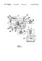
- FIG. 1is a block diagram of an infrared source based pointing device according to a preferred embodiment of the invention
- FIG. 2is a timing diagram showing the scan cycle of IR activation and IR detector output
- FIG. 3is a block diagram showing the finger movement area of FIG. 1 illustrating finger position detection through finger shadow;
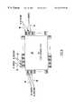
- FIGS. 4A and 4Bare respectively a plan view and a cross-sectional side view of an exemplary physical implementation of the pointer device according to the invention.
- FIG. 5is a block diagram of an infrared source based pointing device showing non-uniform beam widths across the Finger Movement Area according to the invention
- FIG. 6is a block diagram of an infrared source based pointing device showing alternate positioning of IR sources and detectors according to the invention
- FIG. 7is a block diagram of an infrared source based pointing device showing an IR laser scanning subsystem for the x direction according to the invention
- FIG. 8is a block diagram of an infrared source based pointing device showing different finger cross sections for different angles of inclination
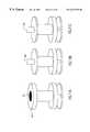
- FIG. 9Ais a schematic of the optical mouse device according to the invention.
- FIG. 9Bis a cross section of the optical mouse device as shown in FIG. 9A;
- FIG. 10Ais a cross section of an optical mouse device showing an IR laser beam in its path
- FIG. 10Bis a cross section of the optical mouse device with the plunger depressed, showing an IR laser beam in its path;
- FIG. 10Cillustrates the shadow created by an optical mouse device
- FIG. 10Dillustrates the shadow created by an optical mouse device with its plunger depressed
- FIGS. 11A, 11 B and 11 Cshow various button heads of an optical mouse device.
- infrared (IR) light sources 11labeled IRC0-IRCm (IR rows 0 to m) and infrared light sources 12 labeled IRC0-IRCn (IR columns 0 to n) produce collimated beams of IR light in each of the x and y directions, respectively.
- IRinfrared
- IRC0-IRCmIR rows 0 to m
- IRC0-IRCninfrared light sources
- FMAFinger Movement Area
- the FMA 15is continuously scanned by IR light in both x and y directions from the IR lights sources 11 and 12 .
- the x-direction IR source controller 16sequentially activates the IR sources 11
- the y-direction IR source controller 17sequentially activates IR sources 12 .
- the actual scan rateis not important, it should be high enough to enable the sensing of the fastest change in finger shadow positions.
- Outputs from IR detectors 13 and 14are respectively processed by signal processing circuits 21 and 22 which provide outputs to pointer control circuit 31 .
- the pointer control circuit 31generates the necessary controls for displaying the pointer on a display screen 32 , such as a Liquid Crystal Display (LCD) as commonly used in laptop computers.
- LCDLiquid Crystal Display
- FIG. 2shows the corresponding activation signals 23 from IR source controller 16 to the IR sources 11 and x-direction detector outputs 21 from IR detectors 13 .
- the signals for the IR source controller 17 to IR sources 12 and the corresponding outputs from the IR detectors 14are similar and therefore not shown.
- the IR detector output DOx at 21is a 1 during all the IR source activation periods.
- FIG. 3shows the situation when a finger 18 is placed in the FMA 15 .
- a finger 18is placed in the FMA 15 .
- x-direction IR rays 19are shown.
- a time-integrated picture with all the rays 19is shown, but in practice, the IR rays are generated sequentially.
- the placement of the fingerproduces a shadow 20 on corresponding ones of IR detectors 13 .
- a finger shadow(not shown for reasons of simplicity of illustration) is produced on certain ones of IR detectors 14 during the y-direction scan.
- x and y direction scansare performed alternately and therefore the reflected rays from the finger falling on IR detectors 13 (and alternatively, IR detectors 14 ) during x-direction (y-direction) scans are ignored.
- the 0-bits obtained from IR detectors 13 and 14provide the information about the finger shadow.
- the bits corresponding to finger edgescan oscillate between 0 and 1. This fluctuation can be handled by using some sort of hysteresis, or fuzzy logic, or some standard image recognition techniques.
- the shadow 20 of the finger 18can be detected continuously by observing the IR signal processing circuit outputs 21 and 22 . Now, if the finger 18 is moved over the FMA 15 , its shadow 20 also moves correspondingly in the x and y directions. The outputs of signal processing circuits 21 and 22 are fed into a pointer control circuit 31 in order to control the pointer movement in a screen display area 32 .
- the pointer positioncan be controlled easily based on the relative movements of the finger shadows. It is possible to change the sensitivity by appropriately scaling the number of bits of shadow movement to the number of pixels of pointer movement. Also, the resolution can be changed by choosing the number of infrared sources 11 and 12 in each direction.
- IR detectorsare not required to practice the present invention. One IR detector each in x and y directions is sufficient. Also, while it is possible to use fiber optics with one or two IR sources and split into one or several beams, this embodiment will require a more complicated method for optically switching the IR light to the appropriate fiber output.
- this new techniquesupports the double clicking function as available in touch pad type of pointing devices. Because it is not easy to distinguish between the placing of a finger to move the pointer and single clicking, single clicking is usually done through one of the “mouse” switches (not shown). Double clicking, however, can be recognized by a short period with no finger shadows occurring between two states with finger shadows.
- FIGS. 4A and 4Bshow some details about an exemplary physical implementation.
- FIG. 4Ais a plan view showing the mouse movement device comprising the FMA 15 , IR light sources 11 and 12 , and IR detectors 13 and 14 , as in FIG. 1 .
- the IR light sources 11 and 12 and the IR detectors 13 and 14would not be visible to the user since these would be covered by the keyboard housing. Only the FMA 15 would be exposed by an opening in the keyboard housing. Adjacent the FMA 15 are two “mouse” keys 41 and 42 .
- these “mouse” keysare positioned above the FMA 15 but could also be located just below the FMA 15 or some other convenient location for quick access by the user's finger.
- the finger movement area (FMA)is not very deep. One can see that only the tip of the finger 18 is necessary to be placed in the movement area 15 to create a shadow. From the relative sizes of the finger 18 , sensors 11 and 12 and the detectors 13 and 14 , it can be seen that the entire mouse positioning device will easily fit into the appropriate area of a laptop computer or similar device.
- FIG. 5shows the FMA 15 , IR light sources 11 and 12 , an IR detectors 13 and 14 .
- An x-direction IR beam 51starts out sharp, but begins to diverge at 53 and produces a divergent beam 52 as it reaches the IR detectors 13 .
- This divergencyleads to non-uniformity for detecting edges of finger or finger operated objects across the FMA 15 .
- the present inventionminimizes this problem by placing the IR sources and detectors alternately along both the opposite peripheries of the FMA, as shown in FIG. 6 .
- IR sources 61are shown as open rectangles, alternately placed with IR detectors 62 which are shown as solid black rectangles.
- the IR sources 61 and IR detectors 62are placed all along the periphery of the FMA 15 , in both the x and y directions.
- FIG. 7shows a schematic of such a touchpad arrangement.
- the low power IR laser source 71generates beams that pass through the optical fibers 72 .
- the x-direction laser beams 73travel across the FMA 15 . Non-obstructed beams are recaptured by optical fibers 74 and detected by IR detectors 75 .
- the IR laser beams usedare of very low power, prolonged exposure to them by a user's finger is not desirable. Therefore, the use of a bare finger must be avoided by providing some other object to be moved by the finger. Further, the use of a bare finger has a basic problem because the cross section of a finger varies widely among users.
- FIG. 8Another problem with using fingers for detection is shown in FIG. 8.
- a finger 81is shown wherein the tip of the finger is almost perpendicular to the FMA 15 .
- a second finger 82is shown at a different inclination.
- the devicemust be able to detect movement of the finger regardless of the inclination and shape of a finger.
- the finger cross sectionscould be at either angle of inclination.
- the finger cross sections seen by the detection systemchange rapidly, leading to jitter in the position of the cursor.
- FIG. 9Ashows a schematic diagram of the new mouse device and FIG. 9B shows the cross section of the device shown in FIG. 9 A.
- the devicehas an opaque plunger 91 which can be depressed by pressing the button 92 on the top.
- a base disk 93At the bottom is a base disk 93 with a central stock 94 .
- the plungeris kept in the lifted position by the spring 95 acting on the button 92 which is attached to the plunger 91 by a hollow cylindrical member 97 .
- the piston 96 attached to the stock 94guides the cylindrical member 97 for vertical movement.
- the stock 94guides the plunger 91 to move vertically.
- FIGS. 10A and 10Bin the normal condition with the plunger 91 uplifted, as shown in FIG. 10A, IR laser beams 98 in a plane between the base disk 93 and the plunger 91 pass through unobstructed, with the exception of those beams in the path of the central stock 94 .
- the opaque plunger 91blocks any laser beams 98 from passing through to the other side.
- FIG. 10Cit may be noted that the shadow 101 of the IR laser beams 98 is narrow, corresponding to the width of the central stock 94 when the plunger is in the normal position.
- FIG. 10DWhen the plunger 91 is depressed, as shown in FIG. 10D, a broader shadow 102 is produced. Therefore, it is possible to determine whether the plunger is depressed or not, by observing the width of the shadow 101 or 102 .
- the mouse deviceis placed on an FMA and moved by using a single finger or by holding the button with two or three fingers.
- the buttonmay be designed for convenience of holding as shown in FIGS. 11A, 11 B and 11 C.
- FIG. 11Ashows a design where the device has a depression 111 in the button 112 , allowing easy movement using one finger.
- FIGS. 11B and 11Cshow a rounded and square finger grip 113 and 114 , respectively.
- the finger griptakes the place of a button.
- activation of cursor controlis achieved by pressing the button and moving the device across the FMA.
- the x-direction beamsare turned on all at once, and plunger depression/position in the x-direction is checked.
- all the y-direction beamsare turned on all at once, and plunger depression/position in the y-direction is checked.
- This alternate sequence x and y direction plunger position checkingis repeated at a rate fast enough to detect the movement of the device. Sequential scanning as described earlier is possible in this case also, but the optical arrangement to switch IR laser beams is generally complicated and expensive.
- This optical mouse devicehas the advantage that its shadows in the x and y directions have a constant width which is equal to the diameter of either the plunger 91 or the stock 94 . This greatly simplifies the process of determination of x and y coordinates of the device on the FMA. Also, the insertion and removal of the plunger from the plane of IR laser beams is always in the vertical direction, and therefore there is no jitter in the final position of the cursor. While the device is particularly suited for use with IR laser beams, it can also be used with normal IR light source based touchpad devices.
- the position and rate of motion of the said mouse device on the FMAcan be easily determined to control the position of cursor on the display screen.
- the action of lifting a conventional mouse and moving from a different starting positionis achieved by releasing the button, moving the mouse to a new position, and starting movement with button depressed. Also double clicking is achieved by just double clicking of the mouse button.
Landscapes
- Engineering & Computer Science (AREA)
- General Engineering & Computer Science (AREA)
- Theoretical Computer Science (AREA)
- Human Computer Interaction (AREA)
- Physics & Mathematics (AREA)
- General Physics & Mathematics (AREA)
- Position Input By Displaying (AREA)
Abstract
Description
Claims (20)
Priority Applications (1)
| Application Number | Priority Date | Filing Date | Title |
|---|---|---|---|
| US09/317,189US6333735B1 (en) | 1999-03-16 | 1999-05-24 | Method and apparatus for mouse positioning device based on infrared light sources and detectors |
Applications Claiming Priority (2)
| Application Number | Priority Date | Filing Date | Title |
|---|---|---|---|
| US09/270,396US20010052895A1 (en) | 1999-03-16 | 1999-03-16 | Method and apparatus for mouse positioning device based on infrared light sources and detector |
| US09/317,189US6333735B1 (en) | 1999-03-16 | 1999-05-24 | Method and apparatus for mouse positioning device based on infrared light sources and detectors |
Related Parent Applications (1)
| Application Number | Title | Priority Date | Filing Date |
|---|---|---|---|
| US09/270,396Continuation-In-PartUS20010052895A1 (en) | 1999-03-16 | 1999-03-16 | Method and apparatus for mouse positioning device based on infrared light sources and detector |
Publications (1)
| Publication Number | Publication Date |
|---|---|
| US6333735B1true US6333735B1 (en) | 2001-12-25 |
Family
ID=46256469
Family Applications (1)
| Application Number | Title | Priority Date | Filing Date |
|---|---|---|---|
| US09/317,189Expired - Fee RelatedUS6333735B1 (en) | 1999-03-16 | 1999-05-24 | Method and apparatus for mouse positioning device based on infrared light sources and detectors |
Country Status (1)
| Country | Link |
|---|---|
| US (1) | US6333735B1 (en) |
Cited By (86)
| Publication number | Priority date | Publication date | Assignee | Title |
|---|---|---|---|---|
| US20020015573A1 (en)* | 2000-03-31 | 2002-02-07 | Akira Ishibashi | Photon operating device and photon operating method |
| US20030222856A1 (en)* | 2002-01-29 | 2003-12-04 | Fedorak Mark V. | Computer pointer control |
| US6703999B1 (en)* | 2000-11-13 | 2004-03-09 | Toyota Jidosha Kabushiki Kaisha | System for computer user interface |
| GB2405247A (en)* | 2003-08-21 | 2005-02-23 | Hewlett Packard Development Co | Position sensing method with window of detector elements providing a unique logic output |
| US20050122308A1 (en)* | 2002-05-28 | 2005-06-09 | Matthew Bell | Self-contained interactive video display system |
| US20050162398A1 (en)* | 2002-03-13 | 2005-07-28 | Eliasson Jonas O.P. | Touch pad, a stylus for use with the touch pad, and a method of operating the touch pad |
| US20060066576A1 (en)* | 2004-09-30 | 2006-03-30 | Microsoft Corporation | Keyboard or other input device using ranging for detection of control piece movement |
| US20060213997A1 (en)* | 2005-03-23 | 2006-09-28 | Microsoft Corporation | Method and apparatus for a cursor control device barcode reader |
| US20060221065A1 (en)* | 2005-04-04 | 2006-10-05 | Hong Yee P | System and method for constructing optical devices using fold-up portions extended from a substrate |
| US20060255248A1 (en)* | 2003-03-12 | 2006-11-16 | Eliasson Jonas O P | System and a method of determining the position of a radiation emitting element |
| US20060284743A1 (en)* | 2005-06-17 | 2006-12-21 | Microsoft Corporation | Input detection based on speckle-modulated laser self-mixing |
| US20070002013A1 (en)* | 2005-06-30 | 2007-01-04 | Microsoft Corporation | Input device using laser self-mixing velocimeter |
| US20070091295A1 (en)* | 2005-10-14 | 2007-04-26 | Microsoft Corporation | Self-mixing laser range sensor |
| US20070102523A1 (en)* | 2005-11-08 | 2007-05-10 | Microsoft Corporation | Laser velocimetric image scanning |
| US20070109268A1 (en)* | 2005-11-14 | 2007-05-17 | Microsoft Corporation | Speckle-based two-dimensional motion tracking |
| US20070109267A1 (en)* | 2005-11-14 | 2007-05-17 | Microsoft Corporation | Speckle-based two-dimensional motion tracking |
| US20070109278A1 (en)* | 2005-11-11 | 2007-05-17 | Samsung Electronics Co., Ltd. | Input apparatus and method using optical sensing, and portable terminal using the same |
| US20070188518A1 (en)* | 2006-02-10 | 2007-08-16 | Microsoft Corporation | Variable orientation input mode |
| US20070201042A1 (en)* | 2003-09-12 | 2007-08-30 | Eliasson Jonas O P | System And Method Of Determining A Position Of A Radiation Emitting Element |
| US20070284429A1 (en)* | 2006-06-13 | 2007-12-13 | Microsoft Corporation | Computer component recognition and setup |
| US20070300182A1 (en)* | 2006-06-22 | 2007-12-27 | Microsoft Corporation | Interface orientation using shadows |
| US20080088593A1 (en)* | 2006-10-12 | 2008-04-17 | Disney Enterprises, Inc. | Multi-user touch screen |
| US7465914B2 (en) | 2003-09-12 | 2008-12-16 | Flatfrog Laboratories Ab | System and method of determining a position of a radiation scattering/reflecting element |
| US20090091553A1 (en)* | 2007-10-03 | 2009-04-09 | Microsoft Corporation | Detecting touch on a surface via a scanning laser |
| US7710391B2 (en) | 2002-05-28 | 2010-05-04 | Matthew Bell | Processing an image utilizing a spatially varying pattern |
| US7809167B2 (en) | 2003-10-24 | 2010-10-05 | Matthew Bell | Method and system for processing captured image information in an interactive video display system |
| US7825902B2 (en) | 2005-03-31 | 2010-11-02 | Avego Technologies General Ip (Singapore) Pte. Ltd. | Controller, system and method for identifying a number of interactions with a computer input area |
| US20100283756A1 (en)* | 2009-05-06 | 2010-11-11 | Ja-Seung Ku | Method and apparatus for recognizing touch |
| US7834846B1 (en) | 2001-06-05 | 2010-11-16 | Matthew Bell | Interactive video display system |
| US20110050639A1 (en)* | 2009-09-02 | 2011-03-03 | Lenovo (Singapore) Pte, Ltd. | Apparatus, method, and system for touch and gesture detection |
| US20110057906A1 (en)* | 2009-09-09 | 2011-03-10 | Stmicroelectronics (Research & Development) Limited | Pointing devices |
| US20110090147A1 (en)* | 2009-10-20 | 2011-04-21 | Qualstar Corporation | Touchless pointing device |
| US20110163998A1 (en)* | 2002-11-04 | 2011-07-07 | Neonode, Inc. | Light-based touch screen with shift-aligned emitter and receiver lenses |
| US20110181552A1 (en)* | 2002-11-04 | 2011-07-28 | Neonode, Inc. | Pressure-sensitive touch screen |
| US8001613B2 (en) | 2006-06-23 | 2011-08-16 | Microsoft Corporation | Security using physical objects |
| US20110242030A1 (en)* | 2010-03-30 | 2011-10-06 | Smk Corporation | Method of outputting input position of touch panel |
| US8035612B2 (en) | 2002-05-28 | 2011-10-11 | Intellectual Ventures Holding 67 Llc | Self-contained interactive video display system |
| US8081822B1 (en) | 2005-05-31 | 2011-12-20 | Intellectual Ventures Holding 67 Llc | System and method for sensing a feature of an object in an interactive video display |
| US8098277B1 (en) | 2005-12-02 | 2012-01-17 | Intellectual Ventures Holding 67 Llc | Systems and methods for communication between a reactive video system and a mobile communication device |
| US8139059B2 (en) | 2006-03-31 | 2012-03-20 | Microsoft Corporation | Object illumination in a virtual environment |
| US8159682B2 (en) | 2007-11-12 | 2012-04-17 | Intellectual Ventures Holding 67 Llc | Lens system |
| US8199108B2 (en) | 2002-12-13 | 2012-06-12 | Intellectual Ventures Holding 67 Llc | Interactive directed light/sound system |
| US8230367B2 (en) | 2007-09-14 | 2012-07-24 | Intellectual Ventures Holding 67 Llc | Gesture-based user interactions with status indicators for acceptable inputs in volumetric zones |
| US8259163B2 (en) | 2008-03-07 | 2012-09-04 | Intellectual Ventures Holding 67 Llc | Display with built in 3D sensing |
| US8300042B2 (en) | 2001-06-05 | 2012-10-30 | Microsoft Corporation | Interactive video display system using strobed light |
| US20130112880A1 (en)* | 2010-07-26 | 2013-05-09 | Sharp Kabushiki Kaisha | Display device |
| US8487866B2 (en) | 2003-10-24 | 2013-07-16 | Intellectual Ventures Holding 67 Llc | Method and system for managing an interactive video display system |
| US8595218B2 (en) | 2008-06-12 | 2013-11-26 | Intellectual Ventures Holding 67 Llc | Interactive display management systems and methods |
| EP2682847A1 (en)* | 2012-07-06 | 2014-01-08 | Ece | Infrared detection device and method with predictible multi-touch tactile control |
| US8791923B2 (en) | 2009-03-27 | 2014-07-29 | Tpk Touch Solutions Inc. | Touching device, laser source module, and laser source structure thereof |
| US8930834B2 (en) | 2006-03-20 | 2015-01-06 | Microsoft Corporation | Variable orientation user interface |
| US9063614B2 (en) | 2009-02-15 | 2015-06-23 | Neonode Inc. | Optical touch screens |
| US9128519B1 (en) | 2005-04-15 | 2015-09-08 | Intellectual Ventures Holding 67 Llc | Method and system for state-based control of objects |
| US9207800B1 (en) | 2014-09-23 | 2015-12-08 | Neonode Inc. | Integrated light guide and touch screen frame and multi-touch determination method |
| US9874978B2 (en) | 2013-07-12 | 2018-01-23 | Flatfrog Laboratories Ab | Partial detect mode |
| US10019113B2 (en) | 2013-04-11 | 2018-07-10 | Flatfrog Laboratories Ab | Tomographic processing for touch detection |
| US10126882B2 (en) | 2014-01-16 | 2018-11-13 | Flatfrog Laboratories Ab | TIR-based optical touch systems of projection-type |
| US10146376B2 (en) | 2014-01-16 | 2018-12-04 | Flatfrog Laboratories Ab | Light coupling in TIR-based optical touch systems |
| US10161886B2 (en) | 2014-06-27 | 2018-12-25 | Flatfrog Laboratories Ab | Detection of surface contamination |
| US10168835B2 (en) | 2012-05-23 | 2019-01-01 | Flatfrog Laboratories Ab | Spatial resolution in touch displays |
| US10247567B2 (en) | 2017-03-20 | 2019-04-02 | International Business Machines Corporation | Short-distance navigation provision |
| US10282035B2 (en) | 2016-12-07 | 2019-05-07 | Flatfrog Laboratories Ab | Touch device |
| US10282034B2 (en) | 2012-10-14 | 2019-05-07 | Neonode Inc. | Touch sensitive curved and flexible displays |
| US10318074B2 (en) | 2015-01-30 | 2019-06-11 | Flatfrog Laboratories Ab | Touch-sensing OLED display with tilted emitters |
| US10401546B2 (en) | 2015-03-02 | 2019-09-03 | Flatfrog Laboratories Ab | Optical component for light coupling |
| US10437389B2 (en) | 2017-03-28 | 2019-10-08 | Flatfrog Laboratories Ab | Touch sensing apparatus and method for assembly |
| US10474249B2 (en) | 2008-12-05 | 2019-11-12 | Flatfrog Laboratories Ab | Touch sensing apparatus and method of operating the same |
| US10481737B2 (en) | 2017-03-22 | 2019-11-19 | Flatfrog Laboratories Ab | Pen differentiation for touch display |
| US10496227B2 (en) | 2015-02-09 | 2019-12-03 | Flatfrog Laboratories Ab | Optical touch system comprising means for projecting and detecting light beams above and inside a transmissive panel |
| US10761657B2 (en) | 2016-11-24 | 2020-09-01 | Flatfrog Laboratories Ab | Automatic optimisation of touch signal |
| US11009972B1 (en)* | 2020-01-17 | 2021-05-18 | Dell Prodcuts L.P. | Portable mouse for an information handling system |
| WO2021105767A1 (en)* | 2019-11-25 | 2021-06-03 | Beechrock Limited | Interaction touch objects |
| US11182023B2 (en) | 2015-01-28 | 2021-11-23 | Flatfrog Laboratories Ab | Dynamic touch quarantine frames |
| US11256371B2 (en) | 2017-09-01 | 2022-02-22 | Flatfrog Laboratories Ab | Optical component |
| US11301089B2 (en) | 2015-12-09 | 2022-04-12 | Flatfrog Laboratories Ab | Stylus identification |
| US11379048B2 (en) | 2012-10-14 | 2022-07-05 | Neonode Inc. | Contactless control panel |
| US11474644B2 (en) | 2017-02-06 | 2022-10-18 | Flatfrog Laboratories Ab | Optical coupling in touch-sensing systems |
| US11567610B2 (en) | 2018-03-05 | 2023-01-31 | Flatfrog Laboratories Ab | Detection line broadening |
| US11669210B2 (en) | 2020-09-30 | 2023-06-06 | Neonode Inc. | Optical touch sensor |
| US11733808B2 (en) | 2012-10-14 | 2023-08-22 | Neonode, Inc. | Object detector based on reflected light |
| US11842014B2 (en) | 2019-12-31 | 2023-12-12 | Neonode Inc. | Contactless touch input system |
| US11893189B2 (en) | 2020-02-10 | 2024-02-06 | Flatfrog Laboratories Ab | Touch-sensing apparatus |
| US11943563B2 (en) | 2019-01-25 | 2024-03-26 | FlatFrog Laboratories, AB | Videoconferencing terminal and method of operating the same |
| US12056316B2 (en) | 2019-11-25 | 2024-08-06 | Flatfrog Laboratories Ab | Touch-sensing apparatus |
| US12055969B2 (en) | 2018-10-20 | 2024-08-06 | Flatfrog Laboratories Ab | Frame for a touch-sensitive device and tool therefor |
| US12282653B2 (en) | 2020-02-08 | 2025-04-22 | Flatfrog Laboratories Ab | Touch apparatus with low latency interactions |
Citations (13)
| Publication number | Priority date | Publication date | Assignee | Title |
|---|---|---|---|---|
| US4868912A (en)* | 1986-11-26 | 1989-09-19 | Digital Electronics | Infrared touch panel |
| US4899138A (en)* | 1987-01-10 | 1990-02-06 | Pioneer Electronic Corporation | Touch panel control device with touch time and finger direction discrimination |
| US5162783A (en)* | 1990-07-23 | 1992-11-10 | Akzo N.V. | Infrared touch screen device for a video monitor |
| US5196835A (en)* | 1988-09-30 | 1993-03-23 | International Business Machines Corporation | Laser touch panel reflective surface aberration cancelling |
| US5424756A (en)* | 1993-05-14 | 1995-06-13 | Ho; Yung-Lung | Track pad cursor positioning device and method |
| US5644338A (en) | 1993-05-26 | 1997-07-01 | Bowen; James H. | Ergonomic laptop computer and ergonomic keyboard |
| US5707160A (en)* | 1992-08-24 | 1998-01-13 | Bowen; James H. | Infrared based computer input devices including keyboards and touch pads |
| US5729250A (en) | 1995-05-08 | 1998-03-17 | International Business Machines Corporation | Front cover assembly for a touch sensitive device |
| US5736687A (en) | 1996-08-21 | 1998-04-07 | Compaq Computer Corporation | Digitizer utilizing heat source detection to receive input information |
| US5943043A (en) | 1995-11-09 | 1999-08-24 | International Business Machines Corporation | Touch panel "double-touch" input method and detection apparatus |
| US5977867A (en) | 1998-05-29 | 1999-11-02 | Nortel Networks Corporation | Touch pad panel with tactile feedback |
| US6008798A (en)* | 1995-06-07 | 1999-12-28 | Compaq Computer Corporation | Method of determining an object's position and associated apparatus |
| US6205021B1 (en) | 1998-02-26 | 2001-03-20 | Micron Electronics, Inc. | Method for operating an input device and a laptop computer |
- 1999
- 1999-05-24USUS09/317,189patent/US6333735B1/ennot_activeExpired - Fee Related
Patent Citations (13)
| Publication number | Priority date | Publication date | Assignee | Title |
|---|---|---|---|---|
| US4868912A (en)* | 1986-11-26 | 1989-09-19 | Digital Electronics | Infrared touch panel |
| US4899138A (en)* | 1987-01-10 | 1990-02-06 | Pioneer Electronic Corporation | Touch panel control device with touch time and finger direction discrimination |
| US5196835A (en)* | 1988-09-30 | 1993-03-23 | International Business Machines Corporation | Laser touch panel reflective surface aberration cancelling |
| US5162783A (en)* | 1990-07-23 | 1992-11-10 | Akzo N.V. | Infrared touch screen device for a video monitor |
| US5707160A (en)* | 1992-08-24 | 1998-01-13 | Bowen; James H. | Infrared based computer input devices including keyboards and touch pads |
| US5424756A (en)* | 1993-05-14 | 1995-06-13 | Ho; Yung-Lung | Track pad cursor positioning device and method |
| US5644338A (en) | 1993-05-26 | 1997-07-01 | Bowen; James H. | Ergonomic laptop computer and ergonomic keyboard |
| US5729250A (en) | 1995-05-08 | 1998-03-17 | International Business Machines Corporation | Front cover assembly for a touch sensitive device |
| US6008798A (en)* | 1995-06-07 | 1999-12-28 | Compaq Computer Corporation | Method of determining an object's position and associated apparatus |
| US5943043A (en) | 1995-11-09 | 1999-08-24 | International Business Machines Corporation | Touch panel "double-touch" input method and detection apparatus |
| US5736687A (en) | 1996-08-21 | 1998-04-07 | Compaq Computer Corporation | Digitizer utilizing heat source detection to receive input information |
| US6205021B1 (en) | 1998-02-26 | 2001-03-20 | Micron Electronics, Inc. | Method for operating an input device and a laptop computer |
| US5977867A (en) | 1998-05-29 | 1999-11-02 | Nortel Networks Corporation | Touch pad panel with tactile feedback |
Cited By (148)
| Publication number | Priority date | Publication date | Assignee | Title |
|---|---|---|---|---|
| US20020015573A1 (en)* | 2000-03-31 | 2002-02-07 | Akira Ishibashi | Photon operating device and photon operating method |
| US6859572B2 (en)* | 2000-03-31 | 2005-02-22 | Sony Corporation | Photon operating device and photon operating method |
| US6703999B1 (en)* | 2000-11-13 | 2004-03-09 | Toyota Jidosha Kabushiki Kaisha | System for computer user interface |
| US7834846B1 (en) | 2001-06-05 | 2010-11-16 | Matthew Bell | Interactive video display system |
| US8300042B2 (en) | 2001-06-05 | 2012-10-30 | Microsoft Corporation | Interactive video display system using strobed light |
| US7109975B2 (en) | 2002-01-29 | 2006-09-19 | Meta4Hand Inc. | Computer pointer control |
| US20030222856A1 (en)* | 2002-01-29 | 2003-12-04 | Fedorak Mark V. | Computer pointer control |
| US20050162398A1 (en)* | 2002-03-13 | 2005-07-28 | Eliasson Jonas O.P. | Touch pad, a stylus for use with the touch pad, and a method of operating the touch pad |
| US20050122308A1 (en)* | 2002-05-28 | 2005-06-09 | Matthew Bell | Self-contained interactive video display system |
| US8035624B2 (en) | 2002-05-28 | 2011-10-11 | Intellectual Ventures Holding 67 Llc | Computer vision based touch screen |
| US8035614B2 (en) | 2002-05-28 | 2011-10-11 | Intellectual Ventures Holding 67 Llc | Interactive video window |
| US8035612B2 (en) | 2002-05-28 | 2011-10-11 | Intellectual Ventures Holding 67 Llc | Self-contained interactive video display system |
| US7710391B2 (en) | 2002-05-28 | 2010-05-04 | Matthew Bell | Processing an image utilizing a spatially varying pattern |
| US8896575B2 (en)* | 2002-11-04 | 2014-11-25 | Neonode Inc. | Pressure-sensitive touch screen |
| US20110181552A1 (en)* | 2002-11-04 | 2011-07-28 | Neonode, Inc. | Pressure-sensitive touch screen |
| US9471170B2 (en) | 2002-11-04 | 2016-10-18 | Neonode Inc. | Light-based touch screen with shift-aligned emitter and receiver lenses |
| US20110163998A1 (en)* | 2002-11-04 | 2011-07-07 | Neonode, Inc. | Light-based touch screen with shift-aligned emitter and receiver lenses |
| US8199108B2 (en) | 2002-12-13 | 2012-06-12 | Intellectual Ventures Holding 67 Llc | Interactive directed light/sound system |
| US20060255248A1 (en)* | 2003-03-12 | 2006-11-16 | Eliasson Jonas O P | System and a method of determining the position of a radiation emitting element |
| US7435940B2 (en) | 2003-03-12 | 2008-10-14 | Flatfrog Laboratories Ab | System and a method of determining the position of a radiation emitting element |
| US20050083298A1 (en)* | 2003-08-21 | 2005-04-21 | Hewlett-Packard Development Company, L.P. | Position sensing method and position sensing apparatus and its construction |
| GB2405247B (en)* | 2003-08-21 | 2007-07-25 | Hewlett Packard Development Co | Position sensing method and position sensing apparatus and its construction |
| GB2405247A (en)* | 2003-08-21 | 2005-02-23 | Hewlett Packard Development Co | Position sensing method with window of detector elements providing a unique logic output |
| US8922478B2 (en) | 2003-08-21 | 2014-12-30 | Hewlett-Packard Development Company, L.P. | Position sensing method and position sensing apparatus and its construction |
| US20070201042A1 (en)* | 2003-09-12 | 2007-08-30 | Eliasson Jonas O P | System And Method Of Determining A Position Of A Radiation Emitting Element |
| US7465914B2 (en) | 2003-09-12 | 2008-12-16 | Flatfrog Laboratories Ab | System and method of determining a position of a radiation scattering/reflecting element |
| US7442914B2 (en) | 2003-09-12 | 2008-10-28 | Flatfrog Laboratories Ab | System and method of determining a position of a radiation emitting element |
| US7809167B2 (en) | 2003-10-24 | 2010-10-05 | Matthew Bell | Method and system for processing captured image information in an interactive video display system |
| US8487866B2 (en) | 2003-10-24 | 2013-07-16 | Intellectual Ventures Holding 67 Llc | Method and system for managing an interactive video display system |
| US7528824B2 (en) | 2004-09-30 | 2009-05-05 | Microsoft Corporation | Keyboard or other input device using ranging for detection of control piece movement |
| US20060066576A1 (en)* | 2004-09-30 | 2006-03-30 | Microsoft Corporation | Keyboard or other input device using ranging for detection of control piece movement |
| US20060213997A1 (en)* | 2005-03-23 | 2006-09-28 | Microsoft Corporation | Method and apparatus for a cursor control device barcode reader |
| US20100315368A1 (en)* | 2005-03-31 | 2010-12-16 | Avago Technologies Ecbu (Singapore) Pte. Ltd. | Controller, System and Method for Identifying a Number of Interactions with a Computer Input Area |
| US7825902B2 (en) | 2005-03-31 | 2010-11-02 | Avego Technologies General Ip (Singapore) Pte. Ltd. | Controller, system and method for identifying a number of interactions with a computer input area |
| US7463248B2 (en)* | 2005-04-04 | 2008-12-09 | Avago Technologies Ecbu Ip (Singapore) Pte. Ltd. | System and method for constructing optical devices using fold-up portions extended from a substrate |
| US20060221065A1 (en)* | 2005-04-04 | 2006-10-05 | Hong Yee P | System and method for constructing optical devices using fold-up portions extended from a substrate |
| US9128519B1 (en) | 2005-04-15 | 2015-09-08 | Intellectual Ventures Holding 67 Llc | Method and system for state-based control of objects |
| US8081822B1 (en) | 2005-05-31 | 2011-12-20 | Intellectual Ventures Holding 67 Llc | System and method for sensing a feature of an object in an interactive video display |
| US7268705B2 (en) | 2005-06-17 | 2007-09-11 | Microsoft Corporation | Input detection based on speckle-modulated laser self-mixing |
| US20060284743A1 (en)* | 2005-06-17 | 2006-12-21 | Microsoft Corporation | Input detection based on speckle-modulated laser self-mixing |
| US7557795B2 (en) | 2005-06-30 | 2009-07-07 | Microsoft Corporation | Input device using laser self-mixing velocimeter |
| US20070002013A1 (en)* | 2005-06-30 | 2007-01-04 | Microsoft Corporation | Input device using laser self-mixing velocimeter |
| US20070091295A1 (en)* | 2005-10-14 | 2007-04-26 | Microsoft Corporation | Self-mixing laser range sensor |
| US7283214B2 (en) | 2005-10-14 | 2007-10-16 | Microsoft Corporation | Self-mixing laser range sensor |
| US7543750B2 (en) | 2005-11-08 | 2009-06-09 | Microsoft Corporation | Laser velocimetric image scanning |
| US20070102523A1 (en)* | 2005-11-08 | 2007-05-10 | Microsoft Corporation | Laser velocimetric image scanning |
| US7961176B2 (en)* | 2005-11-11 | 2011-06-14 | Samsung Electronics Co., Ltd | Input apparatus and method using optical sensing, and portable terminal using the same |
| US20070109278A1 (en)* | 2005-11-11 | 2007-05-17 | Samsung Electronics Co., Ltd. | Input apparatus and method using optical sensing, and portable terminal using the same |
| US20070109268A1 (en)* | 2005-11-14 | 2007-05-17 | Microsoft Corporation | Speckle-based two-dimensional motion tracking |
| US20070109267A1 (en)* | 2005-11-14 | 2007-05-17 | Microsoft Corporation | Speckle-based two-dimensional motion tracking |
| US7505033B2 (en) | 2005-11-14 | 2009-03-17 | Microsoft Corporation | Speckle-based two-dimensional motion tracking |
| US8098277B1 (en) | 2005-12-02 | 2012-01-17 | Intellectual Ventures Holding 67 Llc | Systems and methods for communication between a reactive video system and a mobile communication device |
| US20070188518A1 (en)* | 2006-02-10 | 2007-08-16 | Microsoft Corporation | Variable orientation input mode |
| US7612786B2 (en) | 2006-02-10 | 2009-11-03 | Microsoft Corporation | Variable orientation input mode |
| US8930834B2 (en) | 2006-03-20 | 2015-01-06 | Microsoft Corporation | Variable orientation user interface |
| US8139059B2 (en) | 2006-03-31 | 2012-03-20 | Microsoft Corporation | Object illumination in a virtual environment |
| US20070284429A1 (en)* | 2006-06-13 | 2007-12-13 | Microsoft Corporation | Computer component recognition and setup |
| US20070300182A1 (en)* | 2006-06-22 | 2007-12-27 | Microsoft Corporation | Interface orientation using shadows |
| US7552402B2 (en) | 2006-06-22 | 2009-06-23 | Microsoft Corporation | Interface orientation using shadows |
| US8001613B2 (en) | 2006-06-23 | 2011-08-16 | Microsoft Corporation | Security using physical objects |
| US8022941B2 (en) | 2006-10-12 | 2011-09-20 | Disney Enterprises, Inc. | Multi-user touch screen |
| US20080088593A1 (en)* | 2006-10-12 | 2008-04-17 | Disney Enterprises, Inc. | Multi-user touch screen |
| US10990189B2 (en) | 2007-09-14 | 2021-04-27 | Facebook, Inc. | Processing of gesture-based user interaction using volumetric zones |
| US8230367B2 (en) | 2007-09-14 | 2012-07-24 | Intellectual Ventures Holding 67 Llc | Gesture-based user interactions with status indicators for acceptable inputs in volumetric zones |
| US9811166B2 (en) | 2007-09-14 | 2017-11-07 | Intellectual Ventures Holding 81 Llc | Processing of gesture-based user interactions using volumetric zones |
| US9058058B2 (en) | 2007-09-14 | 2015-06-16 | Intellectual Ventures Holding 67 Llc | Processing of gesture-based user interactions activation levels |
| US10564731B2 (en) | 2007-09-14 | 2020-02-18 | Facebook, Inc. | Processing of gesture-based user interactions using volumetric zones |
| US8184101B2 (en) | 2007-10-03 | 2012-05-22 | Microsoft Corporation | Detecting touch on a surface via a scanning laser |
| US20090091553A1 (en)* | 2007-10-03 | 2009-04-09 | Microsoft Corporation | Detecting touch on a surface via a scanning laser |
| US9229107B2 (en) | 2007-11-12 | 2016-01-05 | Intellectual Ventures Holding 81 Llc | Lens system |
| US8810803B2 (en) | 2007-11-12 | 2014-08-19 | Intellectual Ventures Holding 67 Llc | Lens system |
| US8159682B2 (en) | 2007-11-12 | 2012-04-17 | Intellectual Ventures Holding 67 Llc | Lens system |
| US9247236B2 (en) | 2008-03-07 | 2016-01-26 | Intellectual Ventures Holdings 81 Llc | Display with built in 3D sensing capability and gesture control of TV |
| US10831278B2 (en) | 2008-03-07 | 2020-11-10 | Facebook, Inc. | Display with built in 3D sensing capability and gesture control of tv |
| US8259163B2 (en) | 2008-03-07 | 2012-09-04 | Intellectual Ventures Holding 67 Llc | Display with built in 3D sensing |
| US8595218B2 (en) | 2008-06-12 | 2013-11-26 | Intellectual Ventures Holding 67 Llc | Interactive display management systems and methods |
| US10474249B2 (en) | 2008-12-05 | 2019-11-12 | Flatfrog Laboratories Ab | Touch sensing apparatus and method of operating the same |
| US9063614B2 (en) | 2009-02-15 | 2015-06-23 | Neonode Inc. | Optical touch screens |
| US9678601B2 (en) | 2009-02-15 | 2017-06-13 | Neonode Inc. | Optical touch screens |
| US8791923B2 (en) | 2009-03-27 | 2014-07-29 | Tpk Touch Solutions Inc. | Touching device, laser source module, and laser source structure thereof |
| EP2249233A3 (en)* | 2009-05-06 | 2013-03-20 | Samsung Display Co., Ltd. | Method and apparatus for recognizing touch operation |
| US20100283756A1 (en)* | 2009-05-06 | 2010-11-11 | Ja-Seung Ku | Method and apparatus for recognizing touch |
| US8319751B2 (en) | 2009-09-02 | 2012-11-27 | Lenovo (Singapore) Pte. Ltd. | Apparatus, method, and system for touch and gesture detection |
| US20110050639A1 (en)* | 2009-09-02 | 2011-03-03 | Lenovo (Singapore) Pte, Ltd. | Apparatus, method, and system for touch and gesture detection |
| US8723816B2 (en)* | 2009-09-09 | 2014-05-13 | Stmicroelectronics (Research & Development) Limited | Pointing devices |
| US20110057906A1 (en)* | 2009-09-09 | 2011-03-10 | Stmicroelectronics (Research & Development) Limited | Pointing devices |
| US8907894B2 (en) | 2009-10-20 | 2014-12-09 | Northridge Associates Llc | Touchless pointing device |
| US20110090147A1 (en)* | 2009-10-20 | 2011-04-21 | Qualstar Corporation | Touchless pointing device |
| US20110242030A1 (en)* | 2010-03-30 | 2011-10-06 | Smk Corporation | Method of outputting input position of touch panel |
| US8823681B2 (en)* | 2010-03-30 | 2014-09-02 | Smk Corporation | Method of outputting input position of touch panel |
| US20130112880A1 (en)* | 2010-07-26 | 2013-05-09 | Sharp Kabushiki Kaisha | Display device |
| US8816285B2 (en)* | 2010-07-26 | 2014-08-26 | Sharp Kabushiki Kaisha | Display device |
| US10168835B2 (en) | 2012-05-23 | 2019-01-01 | Flatfrog Laboratories Ab | Spatial resolution in touch displays |
| EP2682847A1 (en)* | 2012-07-06 | 2014-01-08 | Ece | Infrared detection device and method with predictible multi-touch tactile control |
| FR2993067A1 (en)* | 2012-07-06 | 2014-01-10 | Ece | DEVICE AND METHOD FOR INFRARED DETECTION WITH PREFIGIBLE MULTITOUCHER TOUCH CONTROL |
| US11379048B2 (en) | 2012-10-14 | 2022-07-05 | Neonode Inc. | Contactless control panel |
| US10282034B2 (en) | 2012-10-14 | 2019-05-07 | Neonode Inc. | Touch sensitive curved and flexible displays |
| US10949027B2 (en) | 2012-10-14 | 2021-03-16 | Neonode Inc. | Interactive virtual display |
| US11714509B2 (en) | 2012-10-14 | 2023-08-01 | Neonode Inc. | Multi-plane reflective sensor |
| US11733808B2 (en) | 2012-10-14 | 2023-08-22 | Neonode, Inc. | Object detector based on reflected light |
| US10019113B2 (en) | 2013-04-11 | 2018-07-10 | Flatfrog Laboratories Ab | Tomographic processing for touch detection |
| US9874978B2 (en) | 2013-07-12 | 2018-01-23 | Flatfrog Laboratories Ab | Partial detect mode |
| US10146376B2 (en) | 2014-01-16 | 2018-12-04 | Flatfrog Laboratories Ab | Light coupling in TIR-based optical touch systems |
| US10126882B2 (en) | 2014-01-16 | 2018-11-13 | Flatfrog Laboratories Ab | TIR-based optical touch systems of projection-type |
| US10161886B2 (en) | 2014-06-27 | 2018-12-25 | Flatfrog Laboratories Ab | Detection of surface contamination |
| US9207800B1 (en) | 2014-09-23 | 2015-12-08 | Neonode Inc. | Integrated light guide and touch screen frame and multi-touch determination method |
| US9645679B2 (en) | 2014-09-23 | 2017-05-09 | Neonode Inc. | Integrated light guide and touch screen frame |
| US11182023B2 (en) | 2015-01-28 | 2021-11-23 | Flatfrog Laboratories Ab | Dynamic touch quarantine frames |
| US10318074B2 (en) | 2015-01-30 | 2019-06-11 | Flatfrog Laboratories Ab | Touch-sensing OLED display with tilted emitters |
| US10496227B2 (en) | 2015-02-09 | 2019-12-03 | Flatfrog Laboratories Ab | Optical touch system comprising means for projecting and detecting light beams above and inside a transmissive panel |
| US11029783B2 (en) | 2015-02-09 | 2021-06-08 | Flatfrog Laboratories Ab | Optical touch system comprising means for projecting and detecting light beams above and inside a transmissive panel |
| US10401546B2 (en) | 2015-03-02 | 2019-09-03 | Flatfrog Laboratories Ab | Optical component for light coupling |
| US11301089B2 (en) | 2015-12-09 | 2022-04-12 | Flatfrog Laboratories Ab | Stylus identification |
| US10761657B2 (en) | 2016-11-24 | 2020-09-01 | Flatfrog Laboratories Ab | Automatic optimisation of touch signal |
| US11281335B2 (en) | 2016-12-07 | 2022-03-22 | Flatfrog Laboratories Ab | Touch device |
| US10282035B2 (en) | 2016-12-07 | 2019-05-07 | Flatfrog Laboratories Ab | Touch device |
| US10775935B2 (en) | 2016-12-07 | 2020-09-15 | Flatfrog Laboratories Ab | Touch device |
| US11579731B2 (en) | 2016-12-07 | 2023-02-14 | Flatfrog Laboratories Ab | Touch device |
| US12189906B2 (en) | 2016-12-07 | 2025-01-07 | Flatfrog Laboratories Ab | Touch device |
| US11740741B2 (en) | 2017-02-06 | 2023-08-29 | Flatfrog Laboratories Ab | Optical coupling in touch-sensing systems |
| US12175044B2 (en) | 2017-02-06 | 2024-12-24 | Flatfrog Laboratories Ab | Optical coupling in touch-sensing systems |
| US11474644B2 (en) | 2017-02-06 | 2022-10-18 | Flatfrog Laboratories Ab | Optical coupling in touch-sensing systems |
| US10247567B2 (en) | 2017-03-20 | 2019-04-02 | International Business Machines Corporation | Short-distance navigation provision |
| US11016605B2 (en) | 2017-03-22 | 2021-05-25 | Flatfrog Laboratories Ab | Pen differentiation for touch displays |
| US10606414B2 (en) | 2017-03-22 | 2020-03-31 | Flatfrog Laboratories Ab | Eraser for touch displays |
| US11099688B2 (en) | 2017-03-22 | 2021-08-24 | Flatfrog Laboratories Ab | Eraser for touch displays |
| US10481737B2 (en) | 2017-03-22 | 2019-11-19 | Flatfrog Laboratories Ab | Pen differentiation for touch display |
| US10437389B2 (en) | 2017-03-28 | 2019-10-08 | Flatfrog Laboratories Ab | Touch sensing apparatus and method for assembly |
| US11281338B2 (en) | 2017-03-28 | 2022-03-22 | Flatfrog Laboratories Ab | Touch sensing apparatus and method for assembly |
| US10606416B2 (en) | 2017-03-28 | 2020-03-31 | Flatfrog Laboratories Ab | Touch sensing apparatus and method for assembly |
| US10739916B2 (en) | 2017-03-28 | 2020-08-11 | Flatfrog Laboratories Ab | Touch sensing apparatus and method for assembly |
| US10845923B2 (en) | 2017-03-28 | 2020-11-24 | Flatfrog Laboratories Ab | Touch sensing apparatus and method for assembly |
| US11269460B2 (en) | 2017-03-28 | 2022-03-08 | Flatfrog Laboratories Ab | Touch sensing apparatus and method for assembly |
| US12086362B2 (en) | 2017-09-01 | 2024-09-10 | Flatfrog Laboratories Ab | Optical component |
| US11256371B2 (en) | 2017-09-01 | 2022-02-22 | Flatfrog Laboratories Ab | Optical component |
| US11650699B2 (en) | 2017-09-01 | 2023-05-16 | Flatfrog Laboratories Ab | Optical component |
| US11567610B2 (en) | 2018-03-05 | 2023-01-31 | Flatfrog Laboratories Ab | Detection line broadening |
| US12055969B2 (en) | 2018-10-20 | 2024-08-06 | Flatfrog Laboratories Ab | Frame for a touch-sensitive device and tool therefor |
| US11943563B2 (en) | 2019-01-25 | 2024-03-26 | FlatFrog Laboratories, AB | Videoconferencing terminal and method of operating the same |
| WO2021105767A1 (en)* | 2019-11-25 | 2021-06-03 | Beechrock Limited | Interaction touch objects |
| US12056316B2 (en) | 2019-11-25 | 2024-08-06 | Flatfrog Laboratories Ab | Touch-sensing apparatus |
| US11842014B2 (en) | 2019-12-31 | 2023-12-12 | Neonode Inc. | Contactless touch input system |
| US12299238B2 (en) | 2019-12-31 | 2025-05-13 | Neonode Inc. | Contactless touch input system |
| US11009972B1 (en)* | 2020-01-17 | 2021-05-18 | Dell Prodcuts L.P. | Portable mouse for an information handling system |
| US12282653B2 (en) | 2020-02-08 | 2025-04-22 | Flatfrog Laboratories Ab | Touch apparatus with low latency interactions |
| US11893189B2 (en) | 2020-02-10 | 2024-02-06 | Flatfrog Laboratories Ab | Touch-sensing apparatus |
| US12147630B2 (en) | 2020-09-30 | 2024-11-19 | Neonode Inc. | Optical touch sensor |
| US11669210B2 (en) | 2020-09-30 | 2023-06-06 | Neonode Inc. | Optical touch sensor |
Similar Documents
| Publication | Publication Date | Title |
|---|---|---|
| US6333735B1 (en) | Method and apparatus for mouse positioning device based on infrared light sources and detectors | |
| EP0786107B1 (en) | Light pen input systems | |
| KR100325381B1 (en) | A method of implementing touch pad using fingerprint reader and a touch pad apparatus for functioning as fingerprint scan | |
| EP0536554B1 (en) | Method and apparatus for reducing system overhead for a touch screen device | |
| US5767842A (en) | Method and device for optical input of commands or data | |
| US5900863A (en) | Method and apparatus for controlling computer without touching input device | |
| US9274598B2 (en) | System and method for selecting and activating a target object using a combination of eye gaze and key presses | |
| AU2010218345B2 (en) | Dynamic rear-projected user interface | |
| US4812833A (en) | Touch panel input device | |
| JP2986047B2 (en) | Digital input display device and input processing device and method | |
| US5446480A (en) | Input device for entering data for electronic equipments and so forth | |
| US5164713A (en) | Cursor position controller for use with mouse and display systems | |
| US8593414B2 (en) | Optical touch system and operating method thereof | |
| EP2405326A1 (en) | Detection system and method for detecting movements of a movable object | |
| US20100073486A1 (en) | Multi-dimensional input apparatus | |
| KR200477008Y1 (en) | Smart phone with mouse module | |
| CN101882029B (en) | Optical touch system and operating method thereof | |
| US20010052895A1 (en) | Method and apparatus for mouse positioning device based on infrared light sources and detector | |
| US4670738A (en) | Computer input technique | |
| CN1910541A (en) | Versatile optical mouse | |
| KR100339923B1 (en) | Coordinate inputting apparatus using a light and its method | |
| JPH05298016A (en) | Input device for graphics | |
| JPH0667787A (en) | Position input device | |
| JP2001265498A (en) | Information processing device, input device, and input operation processing method | |
| US20060195622A1 (en) | Data input device, information equipment, information equipment control method, and computer program |
Legal Events
| Date | Code | Title | Description |
|---|---|---|---|
| AS | Assignment | Owner name:INTERNATIONAL BUSINESS MACHINES CORPORATION, NEW Y Free format text:ASSIGNMENT OF ASSIGNORS INTEREST;ASSIGNOR:ANVEKAR, DINESH K.;REEL/FRAME:010064/0335 Effective date:19990607 | |
| FEPP | Fee payment procedure | Free format text:PAYOR NUMBER ASSIGNED (ORIGINAL EVENT CODE: ASPN); ENTITY STATUS OF PATENT OWNER: LARGE ENTITY | |
| FPAY | Fee payment | Year of fee payment:4 | |
| AS | Assignment | Owner name:LENOVO (SINGAPORE) PTE LTD.,SINGAPORE Free format text:ASSIGNMENT OF ASSIGNORS INTEREST;ASSIGNOR:INTERNATIONAL BUSINESS MACHINES CORPORATION;REEL/FRAME:016891/0507 Effective date:20050520 Owner name:LENOVO (SINGAPORE) PTE LTD., SINGAPORE Free format text:ASSIGNMENT OF ASSIGNORS INTEREST;ASSIGNOR:INTERNATIONAL BUSINESS MACHINES CORPORATION;REEL/FRAME:016891/0507 Effective date:20050520 | |
| FEPP | Fee payment procedure | Free format text:PAYER NUMBER DE-ASSIGNED (ORIGINAL EVENT CODE: RMPN); ENTITY STATUS OF PATENT OWNER: LARGE ENTITY Free format text:PAYOR NUMBER ASSIGNED (ORIGINAL EVENT CODE: ASPN); ENTITY STATUS OF PATENT OWNER: LARGE ENTITY | |
| REMI | Maintenance fee reminder mailed | ||
| LAPS | Lapse for failure to pay maintenance fees | ||
| STCH | Information on status: patent discontinuation | Free format text:PATENT EXPIRED DUE TO NONPAYMENT OF MAINTENANCE FEES UNDER 37 CFR 1.362 | |
| FP | Lapsed due to failure to pay maintenance fee | Effective date:20091225 |