US6333694B2 - Personal emergency response system - Google Patents
Personal emergency response systemDownload PDFInfo
- Publication number
- US6333694B2 US6333694B2US09/824,296US82429601AUS6333694B2US 6333694 B2US6333694 B2US 6333694B2US 82429601 AUS82429601 AUS 82429601AUS 6333694 B2US6333694 B2US 6333694B2
- Authority
- US
- United States
- Prior art keywords
- user
- sensor
- transceiver
- signal
- central office
- Prior art date
- Legal status (The legal status is an assumption and is not a legal conclusion. Google has not performed a legal analysis and makes no representation as to the accuracy of the status listed.)
- Expired - Lifetime
Links
- 230000004044responseEffects0.000titleclaimsabstractdescription19
- 230000009429distressEffects0.000claimsabstractdescription59
- 238000012544monitoring processMethods0.000abstractdescription9
- 230000004913activationEffects0.000description16
- 230000003213activating effectEffects0.000description9
- 238000001514detection methodMethods0.000description9
- 238000010586diagramMethods0.000description5
- 208000003443UnconsciousnessDiseases0.000description2
- 230000005540biological transmissionEffects0.000description2
- 230000008859changeEffects0.000description2
- 238000012986modificationMethods0.000description2
- 230000004048modificationEffects0.000description2
- 206010008129cerebral palsyDiseases0.000description1
- 208000002173dizzinessDiseases0.000description1
- 230000005484gravityEffects0.000description1
- 230000036541healthEffects0.000description1
- 206010025482malaiseDiseases0.000description1
- 201000006417multiple sclerosisDiseases0.000description1
- 201000006938muscular dystrophyDiseases0.000description1
- 230000000630rising effectEffects0.000description1
Images


Classifications
- G—PHYSICS
- G08—SIGNALLING
- G08B—SIGNALLING OR CALLING SYSTEMS; ORDER TELEGRAPHS; ALARM SYSTEMS
- G08B21/00—Alarms responsive to a single specified undesired or abnormal condition and not otherwise provided for
- G08B21/02—Alarms for ensuring the safety of persons
- G08B21/0202—Child monitoring systems using a transmitter-receiver system carried by the parent and the child
- G08B21/0286—Tampering or removal detection of the child unit from child or article
- G—PHYSICS
- G08—SIGNALLING
- G08B—SIGNALLING OR CALLING SYSTEMS; ORDER TELEGRAPHS; ALARM SYSTEMS
- G08B21/00—Alarms responsive to a single specified undesired or abnormal condition and not otherwise provided for
- G08B21/02—Alarms for ensuring the safety of persons
- G08B21/0202—Child monitoring systems using a transmitter-receiver system carried by the parent and the child
- G08B21/0288—Attachment of child unit to child/article
- G—PHYSICS
- G08—SIGNALLING
- G08B—SIGNALLING OR CALLING SYSTEMS; ORDER TELEGRAPHS; ALARM SYSTEMS
- G08B25/00—Alarm systems in which the location of the alarm condition is signalled to a central station, e.g. fire or police telegraphic systems
- G08B25/01—Alarm systems in which the location of the alarm condition is signalled to a central station, e.g. fire or police telegraphic systems characterised by the transmission medium
- G08B25/016—Personal emergency signalling and security systems
Definitions
- the present inventionrelates generally to alarms and, more particularly, to an alarm that senses when a user has encountered an emergency situation and requires assistance.
- Some individuals living alonemay require assistance, because of age or sickness, to simply rise up from a collapsed state.
- Other individuals, who are victims of multiple sclerosis, cerebral palsy, muscular dystrophy, or simply prone to dizziness or sudden illnessmay similarly require assistance in rising.
- U.S. Pat. No. 4,829,285discloses an improved alarm for sending distress information over a communication link.
- the alarmincludes a tilt switch and a transmitter and is worn by a user.
- the tilt switchsends a tilt signal in response to being turned to a predetermined direction.
- the switchwill send a signal indicating the user's emergency.
- the transmitterreceives the tilt signal and then transmits distress information over a communication link.
- a disadvantage associated with the alarm disclosed in U.S. Pat. No. 4,829,285is that automatic two way audio and voice communication needs to be established between monitoring personnel that receive the distress information from the transmitter and the user wearing the alarm.
- Another disadvantage associated with the alarm disclosed in U.S. Pat. No. 4,829,285is that there needs to be a way for monitoring personnel to determine when the user moves outside of a safety area such that assistance can be provided to the user to safely move outside the safety area.
- a further disadvantage associated with the alarm disclosed in U.S. Pat. No. 4,829,285is that there needs to be a way to alert the monitoring personnel when the user is not wearing the alarm.
- an object of the present inventionto provide an alarm system for sending distress information over a communication link when a user wearing a sensor is in a predetermined position indicative of an emergency and then providing audio communication between the user and personnel monitoring the user in response to the distress information.
- the present inventionprovides an alarm system for sending distress information over a communication link.
- the alarm systemincludes a sensor worn by a user for determining when the user is in a predetermined position indicative of an emergency. The sensor generates a distress signal upon determining that the user is in the predetermined position.
- a personal transceiveris operable with the sensor for receiving the distress signal from the sensor and then transmitting the distress signal over a communication link.
- a central office transceiveris operable with the personal transceiver for receiving the distress signal over the communication link from the personal transceiver. The central office transceiver communicates with the personal transceiver upon receiving the distress signal to provide audio communication between the user and personnel operating the central office transceiver.
- the central office transceivercommunicates with the personal transceiver upon receiving the distress signal to further provide video communication between the user and the personnel operating the central office transceiver.
- the alarm systemincludes a sensor monitor for determining if the sensor is being worn by the user and for generating a sensor monitor signal upon determining that the sensor is not being worn by the user.
- the personal transceiveris operable with the sensor monitor for receiving the sensor monitor signal from the sensor monitor and for transmitting the sensor monitor signal over the communication link to the central office transceiver.
- the central office transceivercommunicates with the personal transceiver upon receiving the sensor monitor signal to provide audio communication between the user and the personnel operating the central office transceiver.
- the present inventionprovides an alarm system for sending distress information over a communication link.
- the alarm systemincludes a sensor worn by a user.
- a personal transceiveris operable with the sensor to monitor the distance therebetween.
- the personal transceivergenerates an improper distance signal when the distance between the personal transceiver and the sensor is greater than a predetermined distance and then transmits the improper distance signal over a communication link.
- a central office transceiveris operable with the personal transceiver for receiving the improper distance signal over the communication link from the personal transceiver.
- the central office transceivercommunicates with the personal transceiver upon receiving the improper distance signal to provide audio communication between the user and personnel operating the central office transceiver.
- FIG. 1illustrates a sensor in accordance with the present invention showing how the sensor is to be worn by a user
- FIG. 2illustrates how the sensor may be activated to send a distress call when the user is in a prone position
- FIG. 3is a block diagram of the sensor
- FIG. 4is a detailed block diagram of the sensor
- FIG. 5is a belt for allowing a user to wear the sensor
- FIG. 6illustrates the back side of the sensor having a slot for receiving a clip provided on the belt
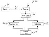
- FIG. 7is a block diagram of the alarm system in accordance with the present invention.
- FIG. 8is a detailed electric schematic of the sensor.
- a sensor 10sends distress information when a user wearing the sensor becomes unconscious or when the user manually signals the need for assistance.
- gravitynormally pulls the body downward. In such cases, the individual can no longer maintain his/her body parallel to a vertical axis and the angle of the persons's body changes relative to that axis. Detection of this change may be used to set off a switch that can enable a transmitter.
- Sensor 10is a pager like device worn by a user 12 on a belt 14 .
- Sensor 10includes an omni-directional tilt switch which is placed perpendicular with respect to belt 14 . This position is chosen as the location of the tilt switch in sensor 10 because this position is often likely to be substantially parallel to a vertical axis 16 running through the user when the user is standing upright.
- a critical angle ⁇ c between the waist of user 12 and vertical axis 16 that causes the tilt switch in sensor 10 to activate the transmitterfalls within the range of 32° to 42°. This critical angle range is sensitive enough to detect the vast majority of collapsed positions, without being overly sensitive to activate the transmitter.
- the most preferred critical angle for activation of the present alarmis determined to be 37° from vertical axis 16 .
- sensor 10generally includes an emergency indicator input 18 interfaced with a control circuit 20 .
- Control circuit 20controls the operation of a transmitter 22 and an audible alarm 24 .
- Control circuit 20controls transmitter 22 to transmit distress information in case of an emergency.
- Control circuit 20controls audible alarm 24 prior to transmission of distress information to alert user 12 that the distress information will be transmitted unless the user desires otherwise.
- Control circuit 20also includes a user feedback circuit 26 .
- User feedback circuit 26enables user 12 to know the state of sensor 10 in order to manually terminate the transmission of distress information.
- a power supply 42such as a battery is connected to control circuit 20 to provide power to sensor 10 .
- emergency indicator input 18includes a panic switch 28 , a transmitter enable switch 30 , a tilt switch 32 , a sensor monitor activation switch 34 , and a low sensor battery detection switch 36 .
- Control circuit 20includes transmitter control logic 38 , timer 40 , and audible alarm control logic 46 .
- Control circuit 20monitors the inputs of emergency indicator input 18 and upon activation of an input controls audible alarm 24 to generate an audible alarm signal. After a predetermined time interval, if user 12 does not reenable sensor 10 in response to the audible alarm signal, then control circuit 20 controls transmitter 22 to transmit distress information.
- panic switch 28can directly transmit distress information using sensor 10 by activating panic switch 28 .
- panic switch 28Upon activation, panic switch 28 provides a panic signal directly to transmitter control logic 38 .
- Transmitter control logic 38then controls transmitter 22 to transmit distress information.
- Tilt switch 32detects a change of angle of the body of user 12 relative to vertical axis 16 . Should user 12 fall while working or lose consciousness while sitting or standing, the angle of the body of user 12 deviates from vertical axis 16 . This deviation activates tilt switch 32 . Control circuit 20 then tests for an emergency condition before controlling transmitter 22 to transmit distress information. If the deviation from vertical axis 16 is continued for more than a predetermined time interval such as ten seconds and user 12 has not manually reset (disabled) sensor 10 using transmitter enable switch 30 or has returned to the normal, upright, substantially vertical position, control circuit 20 controls transmitter 22 to transmit distress information.
- a predetermined time intervalsuch as ten seconds and user 12 has not manually reset (disabled) sensor 10 using transmitter enable switch 30 or has returned to the normal, upright, substantially vertical position
- timer 40determines if tilt switch 32 has been activated for more than the predetermined time interval. After the predetermined time interval has expired, timer 40 provides a timer signal to transmitter control logic 38 . Transmitter control logic 38 then controls transmitter 22 to transmit distress information. User 12 resets timer 40 by activating transmitter enable switch 30 .
- tilt switch 32activates when the critical angle ⁇ c falls within a range of 32° to 42° (no matter which direction the body of user 12 deviates from vertical axis 16 ).
- Tilt switch 32is an omni-directional tilt switch that is sensitive to omni-directional deviations from vertical axis 16 falling within the specific critical range.
- audible alarm control logic 46 of control circuit 20In response to activation of tilt switch 32 , audible alarm control logic 46 of control circuit 20 immediately controls audible alarm 24 to generate an audible alarm signal.
- the audible alarm signalalerts user 12 that tilt switch 32 has been activated and that transmitter 22 will transmit distress information after the predetermined time interval unless user 12 reenables (disables) timer 40 by activating transmitter enable switch 30 .
- sensor monitor activation sensor 34detects whether user 12 is wearing sensor 10 .
- sensor 10is a pager like device worn on belt 14 .
- Belt 14includes a clip 48 which slips into a corresponding slot 50 provided on back of sensor 10 when user 12 is wearing the sensor on the belt.
- Sensor monitor activation switch 34monitors sensor 10 to determine if clip 48 is inserted into slot 50 . If clip 48 is inserted into slot 50 , then sensor monitor activation switch 34 determines that user 12 is wearing sensor 10 . However, if clip 48 is not inserted into slot 50 , then sensor monitor activation switch 34 determines that user 12 is not wearing sensor 10 . In this case, sensor monitor activation switch 34 activates.
- control circuit 20tests for an emergency condition before controlling transmitter 22 to transmit distress information. If user 12 is not wearing sensor 10 for more than a predetermined time interval and user 12 has not manually reset (disabled) sensor 10 using transmitter enable switch 30 or has put sensor 10 back on, control circuit 20 controls transmitter 22 to transmit distress information.
- timer 40determines if sensor monitor activation switch 34 has been activated for more than the predetermined time interval. After the predetermined time interval has expired, timer 40 provides a timer signal to transmitter control logic 38 . Transmitter control logic 38 then controls transmitter 22 to transmit distress information. User 12 resets timer 40 by activating transmitter enable switch 30 .
- audible alarm control logic 46In response to activation of sensor monitor activation switch 34 , audible alarm control logic 46 immediately controls audible alarm 24 to generate an audible alarm signal.
- the audible alarm signalalerts user 12 that sensor monitor activation switch 34 has been activated and that transmitter 22 will transmit distress information after the predetermined time interval unless user 12 reenables (disables) timer 40 by activating transmitter enable switch 30 .
- low sensor battery detection switch 36detects whether power supply 42 has enough power to ensure the proper operation of sensor 10 .
- Low sensor battery detection switch 36activates when the power provided by power supply 42 to sensor 10 falls below a predetermined level.
- control circuit 20In response to low sensor battery detection switch 36 activating, control circuit 20 tests for an emergency condition before controlling transmitter 22 to transmit distress information. If the power falls below the predetermined level for a predetermined time period, control circuit 20 controls transmitter 22 to transmit distress information.
- timer 40determines if low sensor battery detection switch 36 has been activated for more than the predetermined time interval. After the predetermined time interval has expired, timer 40 provides a timer signal to transmitter control logic 38 . Transmitter control logic 38 then controls transmitter 22 to transmit distress information. User 12 resets timer 40 by activating transmitter enable switch 30 .
- audible alarm control logic 46In response to activation of low sensor battery detection switch 36 , audible alarm control logic 46 immediately controls audible alarm 24 to generate an audible alarm signal.
- the audible alarm signalalerts user 12 that low sensor battery detection switch 34 has been activated and that transmitter 22 will transmit distress information after the predetermined time interval.
- Alarm system 70includes sensor 10 , a receiver 54 , and a central office 60 .
- Transmitter 22 of sensor 10transmits distress information over a communication link 52 to a receiver 54 .
- Receiver 54is a stand alone device that is placed in the home of user 12 .
- Receiver 54is connected to an electrical outlet of the house to receive power and may include a temporary standby direct voltage source.
- communication link 52is a radio frequency communication link such that transmitter 22 and receiver 54 communicate with radio frequency signals.
- receiver 54Upon receiving distress information, receiver 54 activates an auto-dialer 56 .
- Auto-dialer 56makes a telephone call over telephone line 58 to central office 60 to provide audio communication between user 12 and personnel at the central office monitoring the user in response to the distress information.
- Auto-dialer 56may also establish video communication with personnel at the central office via a cable line 62 in response to the distress information.
- sensor 10 and receiver 54exchange polling information over communication link 52 .
- the polling informationenables personnel at central office 60 to determine if user 12 moves outside of a predetermined safety area from receiver 54 while wearing sensor 10 .
- transmitter 22transmits polling signals periodically to receiver 54 .
- Receiver 54measures the magnitude of the polling signals to determine if the magnitude is greater than a predetermined magnitude level.
- the magnitude of the polling signalsis inversely proportional to the distance between sensor 10 and receiver 54 .
- the predetermined magnitude levelcan be set to correspond to a safety distance from receiver 54 that user 12 can move about. Upon moving out of the safety area, the magnitude of the polling signal received by receiver 54 will be lower than the predetermined magnitude level.
- Receiver 54may then communicate with sensor 10 to activate audible alarm 24 to alert user 12 that the user has moved out of the predetermined safety area. Receiver 54 tests for an emergency condition before transmitting distress information. If the magnitude of the polling signal received by receiver 54 is less than the predetermined magnitude level for more than a predetermined time interval and user 12 has not manually reset sensor 10 , then receiver 54 transmits distress information.
- receiver 54In response to a polling signal received by receiver 54 having a low magnitude, receiver 54 controls audible alarm control logic 46 to generate an audible alarm signal.
- the audible alarm signalalerts user 12 that the user has moved out of the predetermined safety area and that transmitter 22 will transmit distress information after the predetermined time interval unless user 12 reenables (disables) timer 40 by activating transmitter enable switch 30 .
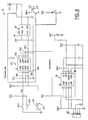
- Sensor 10includes two tilt switches 32 ( a-b ). Two tilt switches are employed to provide finer resolution for selecting the range of the critical angle ⁇ c .
- Timer 40includes a PIC12C508microprocessor 72 .
- Microprocessor 72has four inputs 74 ( a-d ). Input 74 a connects tilt switches 32 ( a-b ) with microprocessor 72 .
- Input 74 cconnects panic switch 28 and transmitter enable switch 30 to microprocessor 72 .
- Input 74 dconnects low sensor battery detection switch to microprocessor 72 .
- Microprocessor 72includes an output 76 a . Output 76 a connects microprocessor 72 to a microprocessor 78 of transmitter control logic 38 .
- Microprocessor 78is connected to transmitter 22 .
Landscapes
- Business, Economics & Management (AREA)
- Emergency Management (AREA)
- Physics & Mathematics (AREA)
- General Physics & Mathematics (AREA)
- Health & Medical Sciences (AREA)
- Child & Adolescent Psychology (AREA)
- General Health & Medical Sciences (AREA)
- Engineering & Computer Science (AREA)
- Computer Security & Cryptography (AREA)
- Alarm Systems (AREA)
- Transmitters (AREA)
Abstract
Description
Claims (8)
Priority Applications (1)
| Application Number | Priority Date | Filing Date | Title |
|---|---|---|---|
| US09/824,296US6333694B2 (en) | 2000-03-09 | 2001-04-02 | Personal emergency response system |
Applications Claiming Priority (2)
| Application Number | Priority Date | Filing Date | Title |
|---|---|---|---|
| PCT/US2000/006087WO2000054236A1 (en) | 1999-03-12 | 2000-03-09 | Personal emergency response system |
| US09/824,296US6333694B2 (en) | 2000-03-09 | 2001-04-02 | Personal emergency response system |
Related Parent Applications (1)
| Application Number | Title | Priority Date | Filing Date |
|---|---|---|---|
| PCT/US2000/006087ContinuationWO2000054236A1 (en) | 1999-03-12 | 2000-03-09 | Personal emergency response system |
Publications (2)
| Publication Number | Publication Date |
|---|---|
| US20010020898A1 US20010020898A1 (en) | 2001-09-13 |
| US6333694B2true US6333694B2 (en) | 2001-12-25 |
Family
ID=25241051
Family Applications (1)
| Application Number | Title | Priority Date | Filing Date |
|---|---|---|---|
| US09/824,296Expired - LifetimeUS6333694B2 (en) | 2000-03-09 | 2001-04-02 | Personal emergency response system |
Country Status (1)
| Country | Link |
|---|---|
| US (1) | US6333694B2 (en) |
Cited By (43)
| Publication number | Priority date | Publication date | Assignee | Title |
|---|---|---|---|---|
| US20040121756A1 (en)* | 2002-12-19 | 2004-06-24 | Griffin Robbin M. | Individual emergency tracking system |
| US6774795B2 (en)* | 2001-06-30 | 2004-08-10 | Koninklijke Philips Electroncs N.V. | Electronic assistant incorporated in personal objects |
| US20050093705A1 (en)* | 2002-05-08 | 2005-05-05 | Charles Humbard | Subscription system for monitoring user well being |
| US7263379B1 (en)* | 2002-12-23 | 2007-08-28 | Sti Licensing Corp. | Communications network for emergency services personnel |
| USD559138S1 (en) | 2006-06-30 | 2008-01-08 | Cothron Candace R | Security alert pendant with GPS unit |
| US20080007396A1 (en)* | 2006-07-10 | 2008-01-10 | Scott Technologies, Inc. | Graphical user interface for emergency apparatus and method for operating same |
| US7398097B2 (en) | 2002-12-23 | 2008-07-08 | Scott Technologies, Inc. | Dual-mesh network and communication system for emergency services personnel |
| US20080261556A1 (en)* | 2005-06-29 | 2008-10-23 | Mclellan Scott W | Mobile Phone Handset |
| US20090002491A1 (en)* | 2005-09-16 | 2009-01-01 | Haler Robert D | Vehicle-mounted video system with distributed processing |
| US20090085873A1 (en)* | 2006-02-01 | 2009-04-02 | Innovative Specialists, Llc | Sensory enhancement systems and methods in personal electronic devices |
| US20090322513A1 (en)* | 2008-06-27 | 2009-12-31 | Franklin Dun-Jen Hwang | Medical emergency alert system and method |
| US20090322548A1 (en)* | 2008-06-27 | 2009-12-31 | Mgpatents | Fall detection system and method |
| US20100052896A1 (en)* | 2008-09-02 | 2010-03-04 | Jesse Bruce Goodman | Fall detection system and method |
| US20100167687A1 (en)* | 2008-10-30 | 2010-07-01 | Digital Ally, Inc. | Multi-functional remote monitoring system |
| US8068051B1 (en)* | 2007-04-24 | 2011-11-29 | Josef Osterweil | Method and apparatus for a body position monitor using radar |
| US20120108912A1 (en)* | 2005-09-29 | 2012-05-03 | Nellcor Puritan Bennett Llc | Method and system for determining when to reposition a physiological sensor |
| US20130214923A1 (en)* | 2010-11-05 | 2013-08-22 | Seniors Wellbeing Pty Ltd | Immobility Monitoring System |
| US20130307696A1 (en)* | 2010-10-20 | 2013-11-21 | Sonitor Technologies As | Position determination system |
| US9253452B2 (en) | 2013-08-14 | 2016-02-02 | Digital Ally, Inc. | Computer program, method, and system for managing multiple data recording devices |
| DE102009015537B4 (en)* | 2009-04-01 | 2016-04-28 | Fraunhofer-Gesellschaft zur Förderung der angewandten Forschung e.V. | Warning system and method for detecting an emergency situation |
| US20160253891A1 (en)* | 2015-02-27 | 2016-09-01 | Elwha Llc | Device that determines that a subject may contact a sensed object and that warns of the potential contact |
| US9712730B2 (en) | 2012-09-28 | 2017-07-18 | Digital Ally, Inc. | Portable video and imaging system |
| US9841259B2 (en) | 2015-05-26 | 2017-12-12 | Digital Ally, Inc. | Wirelessly conducted electronic weapon |
| US9958228B2 (en) | 2013-04-01 | 2018-05-01 | Yardarm Technologies, Inc. | Telematics sensors and camera activation in connection with firearm activity |
| US10013883B2 (en) | 2015-06-22 | 2018-07-03 | Digital Ally, Inc. | Tracking and analysis of drivers within a fleet of vehicles |
| US10075681B2 (en) | 2013-08-14 | 2018-09-11 | Digital Ally, Inc. | Dual lens camera unit |
| US10192277B2 (en) | 2015-07-14 | 2019-01-29 | Axon Enterprise, Inc. | Systems and methods for generating an audit trail for auditable devices |
| US10272848B2 (en) | 2012-09-28 | 2019-04-30 | Digital Ally, Inc. | Mobile video and imaging system |
| US10388080B2 (en) | 2000-08-31 | 2019-08-20 | Strategic Design Federation W, Inc. | Automobile monitoring for operation analysis |
| US10390732B2 (en) | 2013-08-14 | 2019-08-27 | Digital Ally, Inc. | Breath analyzer, system, and computer program for authenticating, preserving, and presenting breath analysis data |
| US10409621B2 (en) | 2014-10-20 | 2019-09-10 | Taser International, Inc. | Systems and methods for distributed control |
| US10521675B2 (en) | 2016-09-19 | 2019-12-31 | Digital Ally, Inc. | Systems and methods of legibly capturing vehicle markings |
| US10764542B2 (en) | 2014-12-15 | 2020-09-01 | Yardarm Technologies, Inc. | Camera activation in response to firearm activity |
| US10904474B2 (en) | 2016-02-05 | 2021-01-26 | Digital Ally, Inc. | Comprehensive video collection and storage |
| US10911725B2 (en) | 2017-03-09 | 2021-02-02 | Digital Ally, Inc. | System for automatically triggering a recording |
| US10964351B2 (en) | 2013-08-14 | 2021-03-30 | Digital Ally, Inc. | Forensic video recording with presence detection |
| US11024142B2 (en) | 2017-07-27 | 2021-06-01 | NXT-ID, Inc. | Event detector for issuing a notification responsive to occurrence of an event |
| US11024137B2 (en) | 2018-08-08 | 2021-06-01 | Digital Ally, Inc. | Remote video triggering and tagging |
| US11158179B2 (en) | 2017-07-27 | 2021-10-26 | NXT-ID, Inc. | Method and system to improve accuracy of fall detection using multi-sensor fusion |
| USD954580S1 (en)* | 2020-04-01 | 2022-06-14 | Freeus, Llc | Mobile personal emergency response system device |
| US11382511B2 (en) | 2017-07-27 | 2022-07-12 | Logicmark, Inc. | Method and system to reduce infrastructure costs with simplified indoor location and reliable communications |
| US11950017B2 (en) | 2022-05-17 | 2024-04-02 | Digital Ally, Inc. | Redundant mobile video recording |
| US12161601B2 (en) | 2018-02-20 | 2024-12-10 | Angel Rodriguez-Cruz | Wheeleta |
Families Citing this family (7)
| Publication number | Priority date | Publication date | Assignee | Title |
|---|---|---|---|---|
| GB0211670D0 (en)* | 2002-05-22 | 2002-07-03 | Univ Edinburgh | Personal alarm systems method and call centre |
| GB0218076D0 (en)* | 2002-08-03 | 2002-09-11 | Kingston John E | Alarm system |
| WO2009058328A1 (en)* | 2007-10-31 | 2009-05-07 | On2Locate, Inc. | Method and system for mobile personal emergency response |
| US8351894B2 (en)* | 2009-02-27 | 2013-01-08 | Research In Motion Limited | Mobile wireless communications device with orientation sensing and related methods |
| FR2949168B1 (en)* | 2009-08-12 | 2012-12-14 | Info Network Systems | FALL DETECTION DEVICE |
| CN107909783B (en)* | 2017-12-22 | 2023-11-14 | 国网河北省电力有限公司衡水供电分公司 | Automatic distress calling device for field operation distress |
| EP4018422B1 (en) | 2019-08-20 | 2024-10-23 | Koninklijke Philips N.V. | System and method of detecting falls of a subject using a wearable sensor |
Citations (14)
| Publication number | Priority date | Publication date | Assignee | Title |
|---|---|---|---|---|
| US3634885A (en) | 1969-11-17 | 1972-01-11 | James H Barkley | Electronic medical warning device |
| US3866204A (en) | 1973-07-19 | 1975-02-11 | James H Barkley | Electronic medical warning device |
| US4284986A (en) | 1980-06-23 | 1981-08-18 | Carlos Amortegui | Shirt-pocket medical alert device |
| US4667188A (en) | 1985-04-25 | 1987-05-19 | Cable Electric Products, Inc. | Portable alarm |
| US4829285A (en) | 1987-06-11 | 1989-05-09 | Marc I. Brand | In-home emergency assist device |
| US4978946A (en) | 1987-08-13 | 1990-12-18 | Talkie Tooter (Canada) Ltd. | Personal security communication system |
| US5014040A (en)* | 1988-10-14 | 1991-05-07 | Instantel Inc. | Personal locator transmitter |
| US5153584A (en)* | 1989-03-17 | 1992-10-06 | Cardiac Evaluation Center, Inc. | Miniature multilead biotelemetry and patient location system |
| US5396227A (en) | 1991-06-26 | 1995-03-07 | Jurismonitor, Inc. | Electronic system and method for monitoring compliance with a protective order |
| US5519380A (en)* | 1994-11-04 | 1996-05-21 | Guardian Electronics, Inc. | Personal monitoring system and method |
| US5967975A (en)* | 1997-11-13 | 1999-10-19 | Ridgeway; Donald G. | Home health parameter monitoring system |
| US5990793A (en) | 1994-09-02 | 1999-11-23 | Safety Tech Industries, Inc. | Firefighters integrated communication and safety system |
| US6166639A (en) | 1999-03-12 | 2000-12-26 | Advanced Marketing Systems Corporation | Personal emergency response system |
| US6185410B1 (en)* | 1997-10-29 | 2001-02-06 | Ted R. Greene | Remote transmitter and method |
- 2001
- 2001-04-02USUS09/824,296patent/US6333694B2/ennot_activeExpired - Lifetime
Patent Citations (14)
| Publication number | Priority date | Publication date | Assignee | Title |
|---|---|---|---|---|
| US3634885A (en) | 1969-11-17 | 1972-01-11 | James H Barkley | Electronic medical warning device |
| US3866204A (en) | 1973-07-19 | 1975-02-11 | James H Barkley | Electronic medical warning device |
| US4284986A (en) | 1980-06-23 | 1981-08-18 | Carlos Amortegui | Shirt-pocket medical alert device |
| US4667188A (en) | 1985-04-25 | 1987-05-19 | Cable Electric Products, Inc. | Portable alarm |
| US4829285A (en) | 1987-06-11 | 1989-05-09 | Marc I. Brand | In-home emergency assist device |
| US4978946A (en) | 1987-08-13 | 1990-12-18 | Talkie Tooter (Canada) Ltd. | Personal security communication system |
| US5014040A (en)* | 1988-10-14 | 1991-05-07 | Instantel Inc. | Personal locator transmitter |
| US5153584A (en)* | 1989-03-17 | 1992-10-06 | Cardiac Evaluation Center, Inc. | Miniature multilead biotelemetry and patient location system |
| US5396227A (en) | 1991-06-26 | 1995-03-07 | Jurismonitor, Inc. | Electronic system and method for monitoring compliance with a protective order |
| US5990793A (en) | 1994-09-02 | 1999-11-23 | Safety Tech Industries, Inc. | Firefighters integrated communication and safety system |
| US5519380A (en)* | 1994-11-04 | 1996-05-21 | Guardian Electronics, Inc. | Personal monitoring system and method |
| US6185410B1 (en)* | 1997-10-29 | 2001-02-06 | Ted R. Greene | Remote transmitter and method |
| US5967975A (en)* | 1997-11-13 | 1999-10-19 | Ridgeway; Donald G. | Home health parameter monitoring system |
| US6166639A (en) | 1999-03-12 | 2000-12-26 | Advanced Marketing Systems Corporation | Personal emergency response system |
Cited By (87)
| Publication number | Priority date | Publication date | Assignee | Title |
|---|---|---|---|---|
| US10388080B2 (en) | 2000-08-31 | 2019-08-20 | Strategic Design Federation W, Inc. | Automobile monitoring for operation analysis |
| US6774795B2 (en)* | 2001-06-30 | 2004-08-10 | Koninklijke Philips Electroncs N.V. | Electronic assistant incorporated in personal objects |
| US11302168B2 (en) | 2002-05-08 | 2022-04-12 | Resource Consortium Limited | Method and system for remotely monitoring a user |
| US8531302B2 (en) | 2002-05-08 | 2013-09-10 | Resource Consortium Limited | Method and system for remotely monitoring a user |
| US7312710B2 (en)* | 2002-05-08 | 2007-12-25 | Charles Humbard | Subscription system for monitoring user well being |
| US9368013B2 (en) | 2002-05-08 | 2016-06-14 | Resource Consortium Limited | Method and system for remotely monitoring a user |
| US20050093705A1 (en)* | 2002-05-08 | 2005-05-05 | Charles Humbard | Subscription system for monitoring user well being |
| US10573152B2 (en) | 2002-05-08 | 2020-02-25 | Resource Consortium Limited, Llc | Method and system for remotely monitoring a user |
| US20100117838A1 (en)* | 2002-05-08 | 2010-05-13 | Resource Consortium Limited | System for remotely monitoring a user |
| US8952806B2 (en) | 2002-05-08 | 2015-02-10 | Resource Consortium Limited | Method and system for remotely monitoring a user |
| US7659826B2 (en) | 2002-05-08 | 2010-02-09 | Resource Consortium Limited | System for remotely monitoring a user |
| US10127787B1 (en) | 2002-05-08 | 2018-11-13 | Resource Consortium Limted | Method and system for remotely monitoring a user |
| US20040121756A1 (en)* | 2002-12-19 | 2004-06-24 | Griffin Robbin M. | Individual emergency tracking system |
| US10536528B2 (en) | 2002-12-23 | 2020-01-14 | Scott Technologies, Inc. | Communications network for emergency services personnel |
| US8755839B2 (en) | 2002-12-23 | 2014-06-17 | Sti Licensing Corp. | Personal multimedia communication system and network for emergency services personnel |
| US7398097B2 (en) | 2002-12-23 | 2008-07-08 | Scott Technologies, Inc. | Dual-mesh network and communication system for emergency services personnel |
| US9257028B2 (en) | 2002-12-23 | 2016-02-09 | Scott Technologies, Inc. | Dual-network locator and communication system for emergency services personnel |
| US7377835B2 (en) | 2002-12-23 | 2008-05-27 | Sti Licensing Corp. | Personal multimedia communication system and network for emergency services personnel |
| US7263379B1 (en)* | 2002-12-23 | 2007-08-28 | Sti Licensing Corp. | Communications network for emergency services personnel |
| US20080261556A1 (en)* | 2005-06-29 | 2008-10-23 | Mclellan Scott W | Mobile Phone Handset |
| US8520069B2 (en) | 2005-09-16 | 2013-08-27 | Digital Ally, Inc. | Vehicle-mounted video system with distributed processing |
| US20090002491A1 (en)* | 2005-09-16 | 2009-01-01 | Haler Robert D | Vehicle-mounted video system with distributed processing |
| US20120108912A1 (en)* | 2005-09-29 | 2012-05-03 | Nellcor Puritan Bennett Llc | Method and system for determining when to reposition a physiological sensor |
| US8690770B2 (en)* | 2005-09-29 | 2014-04-08 | Covidien Lp | Method and system for determining when to reposition a physiological sensor |
| US8390445B2 (en) | 2006-02-01 | 2013-03-05 | Innovation Specialists, Llc | Sensory enhancement systems and methods in personal electronic devices |
| US20110121965A1 (en)* | 2006-02-01 | 2011-05-26 | Innovation Specialists, Llc | Sensory Enhancement Systems and Methods in Personal Electronic Devices |
| US7872574B2 (en)* | 2006-02-01 | 2011-01-18 | Innovation Specialists, Llc | Sensory enhancement systems and methods in personal electronic devices |
| US20090085873A1 (en)* | 2006-02-01 | 2009-04-02 | Innovative Specialists, Llc | Sensory enhancement systems and methods in personal electronic devices |
| USD559138S1 (en) | 2006-06-30 | 2008-01-08 | Cothron Candace R | Security alert pendant with GPS unit |
| US7652571B2 (en) | 2006-07-10 | 2010-01-26 | Scott Technologies, Inc. | Graphical user interface for emergency apparatus and method for operating same |
| US20080007396A1 (en)* | 2006-07-10 | 2008-01-10 | Scott Technologies, Inc. | Graphical user interface for emergency apparatus and method for operating same |
| US8013739B2 (en) | 2006-07-10 | 2011-09-06 | Scott Technologies, Inc. | Graphical user interface for emergency apparatus and method for operating same |
| US8599016B2 (en) | 2006-07-10 | 2013-12-03 | Scott Technologies, Inc. | Graphical user interface for emergency apparatus and method for operating same |
| US8068051B1 (en)* | 2007-04-24 | 2011-11-29 | Josef Osterweil | Method and apparatus for a body position monitor using radar |
| US20090322513A1 (en)* | 2008-06-27 | 2009-12-31 | Franklin Dun-Jen Hwang | Medical emergency alert system and method |
| US20090322548A1 (en)* | 2008-06-27 | 2009-12-31 | Mgpatents | Fall detection system and method |
| US7893844B2 (en)* | 2008-06-27 | 2011-02-22 | Mark Gottlieb | Fall detection system having a floor height threshold and a resident height detection device |
| US20100052896A1 (en)* | 2008-09-02 | 2010-03-04 | Jesse Bruce Goodman | Fall detection system and method |
| US8503972B2 (en) | 2008-10-30 | 2013-08-06 | Digital Ally, Inc. | Multi-functional remote monitoring system |
| US20100167687A1 (en)* | 2008-10-30 | 2010-07-01 | Digital Ally, Inc. | Multi-functional remote monitoring system |
| US10917614B2 (en) | 2008-10-30 | 2021-02-09 | Digital Ally, Inc. | Multi-functional remote monitoring system |
| DE102009015537B4 (en)* | 2009-04-01 | 2016-04-28 | Fraunhofer-Gesellschaft zur Förderung der angewandten Forschung e.V. | Warning system and method for detecting an emergency situation |
| US20130307696A1 (en)* | 2010-10-20 | 2013-11-21 | Sonitor Technologies As | Position determination system |
| US9310207B2 (en)* | 2010-10-20 | 2016-04-12 | Sonitor Technologies As | Position determination system |
| US10368783B2 (en) | 2010-10-20 | 2019-08-06 | Sonitor Technologies As | Position determination system |
| US20130214923A1 (en)* | 2010-11-05 | 2013-08-22 | Seniors Wellbeing Pty Ltd | Immobility Monitoring System |
| US9712730B2 (en) | 2012-09-28 | 2017-07-18 | Digital Ally, Inc. | Portable video and imaging system |
| US11310399B2 (en) | 2012-09-28 | 2022-04-19 | Digital Ally, Inc. | Portable video and imaging system |
| US11667251B2 (en) | 2012-09-28 | 2023-06-06 | Digital Ally, Inc. | Portable video and imaging system |
| US10272848B2 (en) | 2012-09-28 | 2019-04-30 | Digital Ally, Inc. | Mobile video and imaging system |
| US10257396B2 (en) | 2012-09-28 | 2019-04-09 | Digital Ally, Inc. | Portable video and imaging system |
| US9958228B2 (en) | 2013-04-01 | 2018-05-01 | Yardarm Technologies, Inc. | Telematics sensors and camera activation in connection with firearm activity |
| US10866054B2 (en) | 2013-04-01 | 2020-12-15 | Yardarm Technologies, Inc. | Associating metadata regarding state of firearm with video stream |
| US11131522B2 (en) | 2013-04-01 | 2021-09-28 | Yardarm Technologies, Inc. | Associating metadata regarding state of firearm with data stream |
| US10107583B2 (en) | 2013-04-01 | 2018-10-23 | Yardarm Technologies, Inc. | Telematics sensors and camera activation in connection with firearm activity |
| US11466955B2 (en) | 2013-04-01 | 2022-10-11 | Yardarm Technologies, Inc. | Firearm telematics devices for monitoring status and location |
| US10885937B2 (en) | 2013-08-14 | 2021-01-05 | Digital Ally, Inc. | Computer program, method, and system for managing multiple data recording devices |
| US10075681B2 (en) | 2013-08-14 | 2018-09-11 | Digital Ally, Inc. | Dual lens camera unit |
| US10074394B2 (en) | 2013-08-14 | 2018-09-11 | Digital Ally, Inc. | Computer program, method, and system for managing multiple data recording devices |
| US10757378B2 (en) | 2013-08-14 | 2020-08-25 | Digital Ally, Inc. | Dual lens camera unit |
| US9253452B2 (en) | 2013-08-14 | 2016-02-02 | Digital Ally, Inc. | Computer program, method, and system for managing multiple data recording devices |
| US10964351B2 (en) | 2013-08-14 | 2021-03-30 | Digital Ally, Inc. | Forensic video recording with presence detection |
| US10390732B2 (en) | 2013-08-14 | 2019-08-27 | Digital Ally, Inc. | Breath analyzer, system, and computer program for authenticating, preserving, and presenting breath analysis data |
| US11900130B2 (en) | 2014-10-20 | 2024-02-13 | Axon Enterprise, Inc. | Systems and methods for distributed control |
| US10409621B2 (en) | 2014-10-20 | 2019-09-10 | Taser International, Inc. | Systems and methods for distributed control |
| US10901754B2 (en) | 2014-10-20 | 2021-01-26 | Axon Enterprise, Inc. | Systems and methods for distributed control |
| US11544078B2 (en) | 2014-10-20 | 2023-01-03 | Axon Enterprise, Inc. | Systems and methods for distributed control |
| US12386634B2 (en) | 2014-10-20 | 2025-08-12 | Axon Enterprise, Inc. | Systems and methods for distributed control |
| US10764542B2 (en) | 2014-12-15 | 2020-09-01 | Yardarm Technologies, Inc. | Camera activation in response to firearm activity |
| US20160253891A1 (en)* | 2015-02-27 | 2016-09-01 | Elwha Llc | Device that determines that a subject may contact a sensed object and that warns of the potential contact |
| US9841259B2 (en) | 2015-05-26 | 2017-12-12 | Digital Ally, Inc. | Wirelessly conducted electronic weapon |
| US10337840B2 (en) | 2015-05-26 | 2019-07-02 | Digital Ally, Inc. | Wirelessly conducted electronic weapon |
| US10013883B2 (en) | 2015-06-22 | 2018-07-03 | Digital Ally, Inc. | Tracking and analysis of drivers within a fleet of vehicles |
| US11244570B2 (en) | 2015-06-22 | 2022-02-08 | Digital Ally, Inc. | Tracking and analysis of drivers within a fleet of vehicles |
| US10192277B2 (en) | 2015-07-14 | 2019-01-29 | Axon Enterprise, Inc. | Systems and methods for generating an audit trail for auditable devices |
| US10848717B2 (en) | 2015-07-14 | 2020-11-24 | Axon Enterprise, Inc. | Systems and methods for generating an audit trail for auditable devices |
| US10904474B2 (en) | 2016-02-05 | 2021-01-26 | Digital Ally, Inc. | Comprehensive video collection and storage |
| US10521675B2 (en) | 2016-09-19 | 2019-12-31 | Digital Ally, Inc. | Systems and methods of legibly capturing vehicle markings |
| US10911725B2 (en) | 2017-03-09 | 2021-02-02 | Digital Ally, Inc. | System for automatically triggering a recording |
| US11382511B2 (en) | 2017-07-27 | 2022-07-12 | Logicmark, Inc. | Method and system to reduce infrastructure costs with simplified indoor location and reliable communications |
| US11158179B2 (en) | 2017-07-27 | 2021-10-26 | NXT-ID, Inc. | Method and system to improve accuracy of fall detection using multi-sensor fusion |
| US11024142B2 (en) | 2017-07-27 | 2021-06-01 | NXT-ID, Inc. | Event detector for issuing a notification responsive to occurrence of an event |
| US12354456B2 (en) | 2017-07-27 | 2025-07-08 | Logicmark, Inc. | Method and system to improve accuracy of fall detection using multi-sensor fusion |
| US12161601B2 (en) | 2018-02-20 | 2024-12-10 | Angel Rodriguez-Cruz | Wheeleta |
| US11024137B2 (en) | 2018-08-08 | 2021-06-01 | Digital Ally, Inc. | Remote video triggering and tagging |
| USD954580S1 (en)* | 2020-04-01 | 2022-06-14 | Freeus, Llc | Mobile personal emergency response system device |
| US11950017B2 (en) | 2022-05-17 | 2024-04-02 | Digital Ally, Inc. | Redundant mobile video recording |
Also Published As
| Publication number | Publication date |
|---|---|
| US20010020898A1 (en) | 2001-09-13 |
Similar Documents
| Publication | Publication Date | Title |
|---|---|---|
| US6333694B2 (en) | Personal emergency response system | |
| US6166639A (en) | Personal emergency response system | |
| US4829285A (en) | In-home emergency assist device | |
| US5461365A (en) | Multi-hazard alarm system using selectable power-level transmission and localization | |
| US5650770A (en) | Self-locating remote monitoring systems | |
| US8149112B2 (en) | Multi-hazard alarm system using selectable power-level transmission and localization | |
| US7071820B2 (en) | Wireless patient ambulation motion detector and second call system | |
| JP3124757U (en) | Falling emergency call device | |
| JPH10155749A (en) | System for monitoring and informing about human health condition | |
| US9338617B2 (en) | Smart monitoring sensor system for monitoring mobility | |
| GB2323196A (en) | Automatic fall alarm | |
| CN108053612A (en) | Falling over of human body monitor system and its automatic alarm rescue method | |
| WO2001075834A1 (en) | Apparatus and method for detecting an inclination of a body | |
| JP2003036492A (en) | Signal monitoring method, wandering / theft prevention system, wanderer / stolen object tracking support system, care support system, signal monitoring terminal, signal monitoring program, wireless communication terminal, and wireless communication program | |
| CN117496663A (en) | Household safety management system and method for old people | |
| WO2001056471A1 (en) | Patient monitoring devices and methods | |
| JP3830890B2 (en) | Bathroom monitoring device | |
| WO2006137099A2 (en) | System and method of remote monitoring and relief via gsm | |
| KR20020075846A (en) | The method of informing health care and warning sudden death by using mobile and a pulsation watching appliance. | |
| CN211882572U (en) | A smart crutch | |
| JP2004070842A (en) | Error reporting system | |
| JPH0695646B2 (en) | Portable emergency reporting device | |
| JP3558038B2 (en) | Safety confirmation system | |
| JPH04285529A (en) | Device for detecting abnormality occurrence of old people or the like | |
| TWM392408U (en) | Emergency device for warning falling-down |
Legal Events
| Date | Code | Title | Description |
|---|---|---|---|
| STCF | Information on status: patent grant | Free format text:PATENTED CASE | |
| AS | Assignment | Owner name:GUARDIAN MEDICAL MONITORING, INC., MICHIGAN Free format text:ASSIGNMENT OF ASSIGNORS INTEREST;ASSIGNOR:PIERCE, DOUGLAS;REEL/FRAME:014953/0596 Effective date:20031218 | |
| FPAY | Fee payment | Year of fee payment:4 | |
| FPAY | Fee payment | Year of fee payment:8 | |
| FPAY | Fee payment | Year of fee payment:12 | |
| AS | Assignment | Owner name:GUARDIAN MEDICAL MONITORING, LLC, MICHIGAN Free format text:CONVERSION OF CORPORATION TO LLC;ASSIGNOR:GUARDIAN MEDICAL MONITORING, INC.;REEL/FRAME:041941/0325 Effective date:20170227 | |
| AS | Assignment | Owner name:PACIFIC WESTERN BANK, MARYLAND Free format text:ACKNOWLEDGMENT OF SECURITY INTEREST IN INTELLECTUAL PROPERTY;ASSIGNORS:GA BUSINESS PURCHASER LLC;GA NON-UNION GUARD SERVICES PURCHASER LLC;GA UNION GUARD SERVICES PURCHASER LLC;AND OTHERS;REEL/FRAME:042025/0184 Effective date:20170228 | |
| AS | Assignment | Owner name:GA UNION GUARD SERVICES PURCHASER LLC, MICHIGAN Free format text:RELEASE OF SECURITY INTEREST IN INTELLECTUAL PROPERTY;ASSIGNOR:PACIFIC WESTERN BANK;REEL/FRAME:058264/0331 Effective date:20211123 Owner name:GA NON-UNION GUARD SERVICES PURCHASER LLC, MICHIGAN Free format text:RELEASE OF SECURITY INTEREST IN INTELLECTUAL PROPERTY;ASSIGNOR:PACIFIC WESTERN BANK;REEL/FRAME:058264/0331 Effective date:20211123 Owner name:GUARDIAN MEDICAL MONITORING, LLC, MICHIGAN Free format text:RELEASE OF SECURITY INTEREST IN INTELLECTUAL PROPERTY;ASSIGNOR:PACIFIC WESTERN BANK;REEL/FRAME:058264/0331 Effective date:20211123 Owner name:GA BUSINESS PURCHASER LLC, MICHIGAN Free format text:RELEASE OF SECURITY INTEREST IN INTELLECTUAL PROPERTY;ASSIGNOR:PACIFIC WESTERN BANK;REEL/FRAME:058264/0331 Effective date:20211123 |