US6333602B1 - Smart light source with integrated operational parameters data storage capability - Google Patents
Smart light source with integrated operational parameters data storage capabilityDownload PDFInfo
- Publication number
- US6333602B1 US6333602B1US09/459,989US45998999AUS6333602B1US 6333602 B1US6333602 B1US 6333602B1US 45998999 AUS45998999 AUS 45998999AUS 6333602 B1US6333602 B1US 6333602B1
- Authority
- US
- United States
- Prior art keywords
- light source
- light
- controller
- data
- emitting device
- Prior art date
- Legal status (The legal status is an assumption and is not a legal conclusion. Google has not performed a legal analysis and makes no representation as to the accuracy of the status listed.)
- Expired - Lifetime
Links
- 238000013500data storageMethods0.000titleclaimsabstractdescription27
- 230000002596correlated effectEffects0.000claimsabstractdescription12
- 238000001816coolingMethods0.000claimsdescription15
- 238000004891communicationMethods0.000description4
- 238000012546transferMethods0.000description4
- 230000007423decreaseEffects0.000description3
- 238000010586diagramMethods0.000description3
- 238000012552reviewMethods0.000description3
- 239000004065semiconductorSubstances0.000description3
- 239000000919ceramicSubstances0.000description2
- 229910052736halogenInorganic materials0.000description2
- 150000002367halogensChemical class0.000description2
- 238000004519manufacturing processMethods0.000description2
- 230000002028prematureEffects0.000description2
- 238000012360testing methodMethods0.000description2
- 239000000853adhesiveSubstances0.000description1
- 230000001070adhesive effectEffects0.000description1
- 238000004458analytical methodMethods0.000description1
- 230000003466anti-cipated effectEffects0.000description1
- 230000015556catabolic processEffects0.000description1
- 150000001875compoundsChemical class0.000description1
- 230000000875corresponding effectEffects0.000description1
- 238000001723curingMethods0.000description1
- 238000006731degradation reactionMethods0.000description1
- 230000000881depressing effectEffects0.000description1
- 239000004973liquid crystal related substanceSubstances0.000description1
- 230000000873masking effectEffects0.000description1
- 238000012986modificationMethods0.000description1
- 230000004048modificationEffects0.000description1
- 230000003287optical effectEffects0.000description1
- 238000000016photochemical curingMethods0.000description1
- 238000012545processingMethods0.000description1
- 230000005855radiationEffects0.000description1
Images


Classifications
- H—ELECTRICITY
- H05—ELECTRIC TECHNIQUES NOT OTHERWISE PROVIDED FOR
- H05B—ELECTRIC HEATING; ELECTRIC LIGHT SOURCES NOT OTHERWISE PROVIDED FOR; CIRCUIT ARRANGEMENTS FOR ELECTRIC LIGHT SOURCES, IN GENERAL
- H05B41/00—Circuit arrangements or apparatus for igniting or operating discharge lamps
- H05B41/14—Circuit arrangements
- H05B41/36—Controlling
- H—ELECTRICITY
- H05—ELECTRIC TECHNIQUES NOT OTHERWISE PROVIDED FOR
- H05B—ELECTRIC HEATING; ELECTRIC LIGHT SOURCES NOT OTHERWISE PROVIDED FOR; CIRCUIT ARRANGEMENTS FOR ELECTRIC LIGHT SOURCES, IN GENERAL
- H05B47/00—Circuit arrangements for operating light sources in general, i.e. where the type of light source is not relevant
- H05B47/20—Responsive to malfunctions or to light source life; for protection
- H05B47/28—Circuit arrangements for protecting against abnormal temperature
- Y—GENERAL TAGGING OF NEW TECHNOLOGICAL DEVELOPMENTS; GENERAL TAGGING OF CROSS-SECTIONAL TECHNOLOGIES SPANNING OVER SEVERAL SECTIONS OF THE IPC; TECHNICAL SUBJECTS COVERED BY FORMER USPC CROSS-REFERENCE ART COLLECTIONS [XRACs] AND DIGESTS
- Y02—TECHNOLOGIES OR APPLICATIONS FOR MITIGATION OR ADAPTATION AGAINST CLIMATE CHANGE
- Y02B—CLIMATE CHANGE MITIGATION TECHNOLOGIES RELATED TO BUILDINGS, e.g. HOUSING, HOUSE APPLIANCES OR RELATED END-USER APPLICATIONS
- Y02B20/00—Energy efficient lighting technologies, e.g. halogen lamps or gas discharge lamps
- Y02B20/40—Control techniques providing energy savings, e.g. smart controller or presence detection
Definitions
- This inventionrelates to the field of light emitting devices, and in particular, to replaceable bulbs, lamps and other light emitters.
- Specialized light emitting devicessuch as those used in photocuring applications, frequently utilize replaceable light sources which have been designed to emit light within specified parameters, under certain standard operating conditions. Such light sources are typically engineered to rigid standards, and as such are expensive to manufacture and purchase.
- These types of light sourcesalso frequently possess a limited operational lifespan in which the generated light meets acceptable parameters. This lifespan can be shortened by operating the light emitter under non-optimal conditions. The quality of the generated light can also be affected by operating under less than ideal operating conditions.
- the operating temperature of the anode and cathodecan affect the qualities of the light emitted, as well as the lamp's operational lifespan.
- the temperature of the lamp at the time of striking (or restriking) of the lampcan also affect the lamp's performance.
- the performance, including lifespan, of specialized light emittersis typically guaranteed by the manufacturer. Because such emitters tend to be expensive, occasionally they are returned to the manufacturer with a request for a free replacement or other consideration on the basis that the emitter failed to perform within specified parameters for its guaranteed lifespan. Such claims are generally impossible to verify by the manufacturer, since the manufacturer cannot confirm either the number of operating hours the emitter has undergone, or whether the conditions under which the light source was operated conformed to specifications.
- emitters having different output capabilitiesmay be used interchangeably within the same device, for different applications.
- emittersare interchanged for different applications and stored for later use, it can be difficult for a user to ascertain how many operating hours a particular emitter has performed, and hence to predict its remaining useful operational life.
- the present inventionis directed towards a light source, for use in a light emitting device, which stores operational data correlated to its operational life.
- the subject light sourcecomprises a light generator, a sensor for sensing operational parameters of the light generator, and a light source data storage device integrated with the light generator and operatively coupled to the sensor, for storing operating data correlated to the operational parameters of the light emitter.
- the light sourcealso typically has a light source housing, to which are mounted the light generator, the sensor and the light source data storage device.
- the subject inventionis also directed towards a light emitting device in combination with the light source.
- the light emitting deviceincludes a device housing, and a socket for releasably engaging the light source, the socket being mounted to the device housing.
- the light emitting devicealso has a controller operatively coupled to the socket, the controller comprising means for retrieving the operating data from the light source data storage device. Additionally, the light emitting device has a power source mounted to the device housing and operatively coupled to the controller.
- the subject inventionis directed towards a light source for use in a light emitting device having a controller for determining operational parameters of the light source.
- the light sourcehas a housing and a light generator mounted within the housing.
- the light sourcealso has a light source data storage device mounted to the housing and adapted to operatively couple to the controller, for receiving and storing operating data from the controller correlated to the operational parameters of the light source.
- the subject inventionis further directed towards a light source reader in combination with the light source.
- the light source readerhas a reader housing, a socket for releasably engaging the light source, wherein the socket is mounted to the reader housing, a controller operatively coupled to the socket, the controller comprising means for retrieving the operating data from the light source data storage device.
- the readeralso has a power source mounted to the reader housing and operatively coupled to the controller.
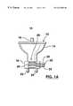
- FIG. 1Ais a side view of a light source made in accordance with the present invention.
- FIG. 1Bis a schematic diagram of the storage device of FIG. 1 A.
- FIG. 1Cis a schematic diagram of the bit allocation of the non-volatile operational parameters memory of the storage device of FIG. 1 B.
- FIG. 1Dis a side view of an alternate embodiment of a light source made in accordance with the present invention.
- FIGS. 1E-1Nare side views of further alternate embodiments of a light source made in accordance with the present invention.
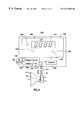
- FIG. 2Ais a top perspective view of a light emitting device made in accordance with the present invention, with the top cover removed and having the light source of FIG. 1A operationally mounted within it.
- FIG. 2Bis a front view of the control data interface of the device of FIG. 2 A.
- FIG. 2Cis a schematic diagram of the controller from the light emitting device of FIG. 2 A.
- FIG. 3is a schematic side view of a handheld light emitting device made in accordance with the present invention, in combination with the light source of FIG. 1 D.
- FIG. 4is a schematic view of a reader made in accordance with the present invention, in combination with the light source of FIG. 1 A.
- the light sourcein this case an arc lamp, shown generally as 10 , comprises a light source housing 12 , a reflector 14 (preferably parabolic in shape), a lamp 16 , a ceramic lamp base 18 , and a light source data storage device 20 .
- the lamp 16comprises an anode 22 and a cathode 24 .
- the light source data storage device 20typically comprises an integrated circuit chip 26 having non-volatile, writable data storage capabilities, such as the EEPROM (electrically erasable programmable read-only memory) programmable digital thermostat chip no. DS1821S, manufactured by Dallas Semiconductor Corporation.
- Chip 26has non-volatile data storage operational parameters memory 28 , which will continue to store data even when power is not supplied to the chip 26 .
- the available memory for operational parameters storage purposesis limited to 16 bits of storage, originally intended to store data relating to maximum and minimum temperature values.
- the chip 26only has a single pin for inputting and outputting data, and utilizes a one-wire communications protocol, as will be understood by one skilled in the art.
- the thirteen lowest order bits B 0 -B 12 of the operational parameters memory 28are used to store run-time data 29 (in binary) correlated to the number of run-time hours the light source 10 has been energized to emit light energy. Thirteen bits are able to represent values ranging from 0 to 9191, in binary. However, arc lamps and other light sources are typically only rated to operate within specified parameters for approximately one thousand to four thousand hours. Accordingly, as will be understood by one skilled in the art, for greater run-time accuracy, the value of the run-time data may directly correlate to the number of fifteen minute or half hour intervals of run-time operation, as appropriate.
- the three highest order bits B 13 -B 15are reserved as condition flags 31 , each of which is originally set to ‘0’ during manufacturing of the chip 26 , as will be understood by one skilled in the art.
- Maximum temperature bit B 13is set to ‘1’ if the maximum operating temperature of the light source 10 has been exceeded during operation.
- Premature termination bit B 14is set to ‘1’ if the light source 10 is energized to emit light energy for less than two minutes before the light source 10 is deenergized.
- Light source failure bit B 15is set to ‘1’ if the light source 10 shuts off prematurely during a light generation period, which may occur for example as a result of a voltage spike from the power supply.
- the storage device 20is preferably mounted to the light source housing 12 , typically through the use of a high temperature, thermally conductive adhesive compound on the lamp base 18 .
- the storage device 20also comprises power 30 , ground 32 and data input/output 34 leads.
- the storage device 20also comprises a sensor 36 for sensing the lamp's 16 temperature, as well as temperature memory 38 for storing data correlated to the sensed temperature.
- a “light generation period”is intended to mean the period of time from the point at which energy is supplied to the lamp 16 energizing it and causing it to generate light energy, to the point at which the supply of power to the lamp 16 is terminated.
- FIG. 1Dshows an alternative embodiment of the light source, shown generally as 50 .
- the light source 50(an arc lamp), comprises a light source housing 52 , a reflector 54 (preferably parabolic in shape), a lamp 56 , a ceramic lamp base 58 , a light source data storage device 60 , and an anode 62 and cathode 64 .
- the light source data storage device 60comprises a non-volatile RAM (random access memory) chip 66 (or similar non-volatile writable memory) which may typically possess at least 1K (kilobyte) of addressable memory. With such an extensive quantity of data storage available, the data storage device 60 is capable of storing more detailed information with respect to the operating parameters of the light source 50 , than the data storage device 20 of FIG. 1 A. Additionally, the data storage device 60 also comprises multiple I/O (input/output) leads 68 , as well as power 70 and ground 72 leads.
- I/Oinput/output
- Data storage 60preferably stores such operational parameters such as the number of light generation periods the light source 50 has undergone, as well as the duration of each generation period, the total amount of time of all the generation periods (also referred to herein as the total run-time), and the light source's 50 temperature at the commencement of each generation period, as well as the light source's 50 temperature over time (if sufficient memory is available). Additionally, the data storage 60 will preferably store data relating to the operation of the light source 50 outside of specified parameters. Such data preferably includes the number of light generation periods during which the temperature of the light source 50 exceeded the maximum operating temperature.
- such datawill preferably include the number of occasions on which the lamp 56 was struck (or restruck) when the temperature of the lamp 56 exceeded specified parameters for striking or restriking (if the controller of the light emitting device used with the light source is not programmed to prevent such occurrences), the number of light generation periods that were less than two minutes in duration, the number of times the lamp 56 failed to strike when energized (if any), and the number of times that the lamp 56 self-extinguished or shut off prematurely during a light generation period (which may occur for example as a result of a voltage spike from the power supply).
- light sources 10 , 50 of the first and alternative embodimentsare illustrated and described as being arc lamps, other types of light sources could be used for different types of applications, and which are subject to the current invention.
- Such light sourcesmay include light emitting semiconductors (such as LEDs), incandescent light bulbs, halogen bulbs, and fluorescent bulbs (either singly or in groups).
- light sourceis not intended to be limited to generators of visible light-generators of infrared and ultraviolet radiation are also intended to be included within the scope of “light source”.
- FIGS. 1E-1NIllustrated in FIGS. 1E-1N are side views of further alternate embodiments of a light source made in accordance with the present invention.
- Such further alternate embodimentsinclude a single LED 82 (FIG. 1E) or 84 (FIG. 1 F), an array 86 (FIG. 1G) or 88 (FIG. 1H) of LEDs 90 , an incandescent light bulb 92 (FIG. 1I) or 94 (FIG. 1 J), a halogen bulb 96 (FIG. 1K) or 97 (FIG. 1L) or a fluorescent bulb 98 (FIG. 1M) or 99 (FIG. 1 N).
- Such alternative embodimentsinclude a storage device 20 or 60 , similar to the storage devices 20 , 60 of FIGS. 1A and 1C.
- Light emitting device 100is generally similar to standard industrial light curing devices, such as that shown and described in U.S. Pat. No. 5,521,392, issued to Kennedy et al., with differences which are apparent from the discussion below.
- Light emitting device 100comprises a device housing 102 , a power supply 104 , a controller 106 , a control data interface 108 , a cooling mechanism 110 , and an emitter 112 .
- the light source 10is removably mounted within the light emitting device 100 .
- the light source 10is mounted to the light emitter 112 using a socket 114 adapted to receive the light source 10 , and the anode 22 and cathode 24 pins (not visible) are operatively coupled to a lamp ballast 113 (which receives power from the power supply 104 ).
- the power 30 , ground 32 and the data 34 leadsare operatively connected to the controller 106 via an electrical connector 116 .
- the controller 106converts power supplied by the power supply 104 to a voltage level which the chip 26 requires to operate.
- the emitter 112has a clamp 118 or similar means for mounting the light source 10 in proper optical alignment with the emitter 112 .
- the emitter 112also includes a bandpass filter 120 , a shutter mechanism 122 , and a light guide 124 .
- the power supply 104may include an electrical cord 126 for connection to a standard electrical outlet, or other means such as a battery capable of providing sufficient electrical energy, in such manner as would be understood by one skilled in the art. Power supply 104 carefully regulates the power supplied to the light source 10 and to the cooling mechanism 110 , in accordance with control signals from the controller 106 , as described in greater detail, below. As will be understood, the power supplied to the light source 10 is preferably independent from the power supplied to the cooling mechanism 110 .
- the control data interface 108preferably comprises a display 128 and an input panel 130 .
- the display 128will typically be an LCD (liquid crystal display) or LED (light emitting diode) panel capable of displaying alphanumeric data to the user
- the input panel 130typically comprises a combination of command buttons, such as start/stop 134 (which initiates/terminates a light emitting period when light is emitted through the light guide 124 ), lamp power on/off 136 and display mode 138 (which selects the type of data to be displayed on the panel 130 , such as current light source 10 temperature, total light source 10 run time hours, length of current light generation period, length of current light emitting period, etc.), as well as several soft keys 140 , through which the user is able to input command signals to the controller 106 typically with respect to the nature and duration of a light emitting period(s). Similar types of control data interfaces are known in the art.
- arc lamps similar to the light source 10generate significant amounts of heat when energized. Additionally, arc lamps may be damaged by striking or restriking when the lamp is too hot. If a lamp is permitted to remain energized when its temperature becomes too high, the quality of the generated light may be affected, and the lamp may also suffer damage, thereby reducing its operational life.
- the controller 106(typically a circuit board) comprises a suitably programmed CPU (central processing unit) 150 , including both RAM 152 and ROM 154 .
- the controller 106is operatively coupled to the power supply 104 , both to draw power for the controller's 106 operation, and also to regulate the supply of power to the cooling mechanism 110 and to control the application of power to the light source 10 , in order to optimize the operating conditions of the light source 10 .
- the controller 106is also operatively coupled to the control data interface 108 , as well as the emitter 112 .
- the controller 106is also operatively coupled to the data storage device 20 (when a light source 10 is mounted in the device 100 , as shown by the dotted outline in FIG. 2 C), and is programmed to download and update the run-time hours data 29 and the condition flags 31 stored in the operational parameters memory 28 , as well as to download temperature data stored in the temperature memory 38 correlated to the sensed temperature of the light source 10 .
- the CPU 150also comprises an input/output module 157 which coordinates the transfer of data and command signals between the controller 106 and the other components 104 , 108 and 112 of the device 100 , and is also programmed to utilize the one-wire communication protocol of the chip 26 , to enable the transfer of data between the controller 106 and the data storage device 20 .
- the CPU 150also comprises a clock mechanism 156 which enables the CPU 150 to track time.
- the CPU 150is programmed to track the number of hours of a light generation period (in addition to the duration of a light emitting period).
- the CPU 150downloads the data stored in bits B 0 -B 15 of the operational parameters memory 28 .
- the CPU 150then masks out the three highest order bits B 13 -B 15 , and adds the number of hours in the completed light generation period (rounded to the nearest hour) to the number (of run-time hours) retrieved from bits B 0 -B 12 of the operational parameters memory 28 . Again, through the use of masking, the updated number of run-time hours is stored in bits B 0 -B 12 .
- the controller 106In the event that the controller 106 receives a command signal from the control data interface 108 (by the user) to initiate a generation period, the controller 106 downloads the temperature data from the temperature memory 38 . The temperature data is then compared to previously stored data correlated to the maximum striking temperature for the light source 10 . If the sensed temperature data exceeds the maximum striking temperature data (indicating that the lamp is too hot for striking), then the controller 106 will prevent the power supply 104 from supplying power to the light source 10 .
- controller 106will preferably be programmed to prevent the power supply 104 from supplying power to the light source 10 if the number of run-time hours for the light source 10 stored in operational parameters memory 28 exceeds a predetermined optimal number, such as two thousand five hundred (2500) hours.
- the controller 106is preferably programmed to set premature termination bit B 15 in the operational parameters memory 28 to ‘1’ if a light generation period has been terminated less than two minutes before it commenced (ie. before the light source 10 has completely warmed up).
- the CPU 150continuously monitors the operation of the light source 10 .
- the CPU 150repeatedly downloads the sensed temperature of the light source 10 from the temperature memory 38 .
- the temperature memory 38is updated by the sensor 36 , when the sensor 36 receives a command signal from the CPU 150 to do so.
- the sensor 36may be configured to automatically update the temperature memory 38 on regular intervals.
- the controller 106During a light generation period, if the temperature data retrieved from the temperature memory 38 is greater than a predetermined maximum value (indicating that the light source 10 is operating at a temperature higher than a predetermined maximum level), the controller 106 generates a control signal to the power supply 104 to discontinue providing power to the light source 10 , and thereby terminate the generation period. Such an automatic shutdown reduces the risk that the light source 10 might explode, and helps prevent extraordinary degradation of the operational life of the light source 10 .
- the controller 106is preferably programmed to then set maximum temperature bit B 13 to ‘1’.
- the controller 106multiplies the sensed temperature by a predetermined cooling mechanism voltage factor, to determine a cooling mechanism power voltage.
- the controller 106then generates a command signal to the power supply 104 to supply power to the cooling mechanism 110 at a voltage correlated to the determined cooling mechanism power voltage. Accordingly, the supply of power to the cooling mechanism 110 varies directly with the sensed temperature of the light source 10 .
- An increase in the amount of power to the cooling mechanism 110(typically a fan), causes the cooling mechanism to circulate air, ventilating warmer air from inside the device housing 102 and drawing in cooler air from outside the housing 102 , causing a corresponding decrease in the operating temperature of the light source 10 .
- the voltage supplied to the cooling mechanism 110correspondingly decreases, as well.
- the CPU 150may be programmed to issue a warning to the user about the excessive operating temperature via the control data interface 108 —the user would then be able to make the decision whether or not to terminate the light generation period. If at any time the sensed temperature exceeds a predetermined maximum operating temperature, as noted, the CPU 150 appropriately flags this condition by setting bit B 13 to “1”, at the end of the generation period when the operational parameters memory 18 is updated.
- the light emitting device 100 with the light source 10is used in much the same manner as known light emitting devices (such as the device disclosed in U.S. Pat. No. 5,521,392, issued to Kennedy et al.).
- a usermay review the data stored in the operational parameters memory 28 through the use of the control data interface 108 .
- the userwill specifically be interested in determining the number of run-time hours that the light source 10 has undergone (stored in bits B 0 -B 12 of the operational parameters memory 28 ), as well as the expected number of operational run-time hours remaining in the life of the light source 10 .
- the usermay also be interested in reviewing the sensed temperature data, stored in the temperature memory 38 .
- FIG. 3illustrated therein is a schematic side view of a hand held light emitting device, shown generally as 160 , with the light source 50 operationally coupled to the device 160 .
- Light emitting device 160comprises a device housing 162 , a power supply 164 , a controller 166 , a control data interface 168 , a cooling mechanism 170 (typically a fan), an emitter 172 , and a light source temperature sensor 174 .
- the controller 166 , the control data interface 168 , and the power supply 164will be substantially similar to the controller 106 , control data interface 108 and power supply 104 of the light emitting device 100 of FIG. 2A, although the control data interface 168 will likely be smaller in size. Additionally, the light emitting start/stop button 134 will typically be replaced by a trigger mechanism 175 .
- the controller 166also differs somewhat in that it has been programmed to download and store operational parameters data from and store updated data in addressable memory locations on the non-volatile RAM chip 62 , as will be understood by one skilled in the art. Additionally, the controller 166 receives temperature data from the sensor 174 , which is typically located proximate the mounted light source 50 .
- the sensor 174may be the digital thermostat chip no. DS1821S, manufactured by Dallas Semiconductor Corporation.
- the reader device 200includes a reader housing 202 , a power supply 204 , a controller 206 and a control data interface 208 mounted on the housing 202 .
- the light source 10is removably coupled to the reader device 200 .
- Power 30 , ground 32 and data 34 leadsare connected to the controller 206 via a releasable electrical connector 212 which is external to the housing 202 .
- the controller 206converts power supplied by the power supply 204 to a voltage level which the chip 26 requires to operate.
- the controller 206comprises a suitably programmed CPU 216 , including both RAM 218 and ROM 220 .
- the CPU 216is programmed to retrieve selected operational parameter data stored in the operational parameters data storage 28 , using one wire communications protocol.
- the CPU 216also comprises an input/output module 217 which is programmed to utilize the one-wire communication protocol of the chip 26 , to enable the transfer of data between the controller 206 and the data storage device 20 .
- controller 206 and power supply 204are illustrated as being located in the housing 202 , alternatively, it should be understood that with appropriate modifications the controller 206 , and the power supply 204 may form part of a standard computer, to which the reader 200 is attached as an external device.
- the control data interface 208includes a display 222 and an input panel of command buttons 224 .
- the display 222will typically be an LCD or LED panel capable of displaying alphanumeric data to the user, and the command buttons 224 typically include display mode 228 (similar to the display mode button 138 of FIG. 2 B), as well as reset 230 (to commence the transfer of data between the storage device 20 and the reader 200 ), and temperature 232 (which tests the temperature sensor 36 of the light source 10 ), through which the user is able to input command signals to the controller 206 .
- the command signalsare received by the controller 206 , and used to select operational parameter data stored in the operational parameter memory 28 or alternately to obtain a temperature reading from the sensor 36 , for display on the display 222 .
- the controlleralso comprises a data I/O port 232 , which may be connected to a remote computer.
- the operational parameters datamay then be downloaded to the remote computer and stored in a database of operational parameter data from other light sources for statistical or other analyses.
- a light sourcesuch as light source 10
- the reader 200in the manner illustrated and described in reference to FIG. 4 .
- a useris able to review the light source's 10 operational parameter data stored in the operational parameters data storage. The user is then able to review the light source's 10 number of run-time hours, as well as whether any of the condition flags have been set indicating that the light source 10 has been abused, and also to test that the sensor 36 is working.
Landscapes
- Circuit Arrangement For Electric Light Sources In General (AREA)
- Endoscopes (AREA)
- Photometry And Measurement Of Optical Pulse Characteristics (AREA)
Abstract
Description
Claims (6)
Priority Applications (6)
| Application Number | Priority Date | Filing Date | Title |
|---|---|---|---|
| US09/459,989US6333602B1 (en) | 1999-12-14 | 1999-12-14 | Smart light source with integrated operational parameters data storage capability |
| CA002325304ACA2325304C (en) | 1999-12-14 | 2000-11-10 | Smart lamp |
| PCT/CA2000/001471WO2001045471A1 (en) | 1999-12-14 | 2000-12-08 | Smart lamp |
| DE10085312TDE10085312T1 (en) | 1999-12-14 | 2000-12-08 | Smart lamp |
| AU21356/01AAU2135601A (en) | 1999-12-14 | 2000-12-08 | Smart lamp |
| US09/986,893US6847170B2 (en) | 1999-12-14 | 2001-11-13 | Smart light source with integrated operational parameters data storage capability |
Applications Claiming Priority (1)
| Application Number | Priority Date | Filing Date | Title |
|---|---|---|---|
| US09/459,989US6333602B1 (en) | 1999-12-14 | 1999-12-14 | Smart light source with integrated operational parameters data storage capability |
Related Child Applications (1)
| Application Number | Title | Priority Date | Filing Date |
|---|---|---|---|
| US09/986,893ContinuationUS6847170B2 (en) | 1999-12-14 | 2001-11-13 | Smart light source with integrated operational parameters data storage capability |
Publications (1)
| Publication Number | Publication Date |
|---|---|
| US6333602B1true US6333602B1 (en) | 2001-12-25 |
Family
ID=23826964
Family Applications (2)
| Application Number | Title | Priority Date | Filing Date |
|---|---|---|---|
| US09/459,989Expired - LifetimeUS6333602B1 (en) | 1999-12-14 | 1999-12-14 | Smart light source with integrated operational parameters data storage capability |
| US09/986,893Expired - LifetimeUS6847170B2 (en) | 1999-12-14 | 2001-11-13 | Smart light source with integrated operational parameters data storage capability |
Family Applications After (1)
| Application Number | Title | Priority Date | Filing Date |
|---|---|---|---|
| US09/986,893Expired - LifetimeUS6847170B2 (en) | 1999-12-14 | 2001-11-13 | Smart light source with integrated operational parameters data storage capability |
Country Status (5)
| Country | Link |
|---|---|
| US (2) | US6333602B1 (en) |
| AU (1) | AU2135601A (en) |
| CA (1) | CA2325304C (en) |
| DE (1) | DE10085312T1 (en) |
| WO (1) | WO2001045471A1 (en) |
Cited By (24)
| Publication number | Priority date | Publication date | Assignee | Title |
|---|---|---|---|---|
| US20020097205A1 (en)* | 2001-01-23 | 2002-07-25 | Canon Kabushiki Kaisha | Semiconductor manufacturing apparatus |
| US20020105285A1 (en)* | 2000-12-01 | 2002-08-08 | Loughrey James F. | Variable output single constant source light fixture |
| WO2002067185A1 (en)* | 2001-02-20 | 2002-08-29 | Syris Scientific, Llc | Lighting apparatus and light control method |
| US6611110B1 (en)* | 2001-01-16 | 2003-08-26 | Design Rite, Llc | Photopolymerization apparatus |
| US6621239B1 (en)* | 2000-03-14 | 2003-09-16 | Richard S. Belliveau | Method and apparatus for controlling the temperature of a multi-parameter light |
| EP1414278A1 (en)* | 2002-10-26 | 2004-04-28 | Hewlett-Packard Development Company, L.P. | Apparatus and method for monitoring the filetime of a projector lamp in accordance with a high-temperature policy |
| US20040240132A1 (en)* | 2003-05-30 | 2004-12-02 | Hudson Christopher A. | Hid dimming system interface box |
| US6847170B2 (en)* | 1999-12-14 | 2005-01-25 | Exfo Photonic Solutions Inc. | Smart light source with integrated operational parameters data storage capability |
| US20050025383A1 (en)* | 2003-07-02 | 2005-02-03 | Celartem Technology, Inc. | Image sharpening with region edge sharpness correction |
| US20050169014A1 (en)* | 2004-01-30 | 2005-08-04 | Koegler John M.Iii | Replaceable lamp header for positioning a lamp within a reflector assembly |
| US20060146553A1 (en)* | 2004-10-08 | 2006-07-06 | B/E Aerospace, Inc. | Dimmable reading light with emergency lighting capability |
| US20060267521A1 (en)* | 2005-05-27 | 2006-11-30 | Matthew Beasley | Light source module |
| GB2430275A (en)* | 2005-09-15 | 2007-03-21 | Tyco Electronics | Electronic control gear for monitoring and controlling lamps |
| WO2008058916A1 (en)* | 2006-11-17 | 2008-05-22 | Osram Gesellschaft mit beschränkter Haftung | Lamp with an operating monitor and operating monitor for a lamp |
| US20080228508A1 (en)* | 2007-03-13 | 2008-09-18 | Renaissance Lighting, Inc. | Monitoring connect time and time of operation of a solid state lighting device |
| US20090109431A1 (en)* | 2007-10-26 | 2009-04-30 | Delmonico James J | Visual inspection apparatus having light source bank |
| US7535184B1 (en) | 2001-01-16 | 2009-05-19 | Design Rite Llc | Photopolymerization apparatus |
| CN101261433B (en)* | 2007-03-09 | 2010-06-09 | 索尼株式会社 | Projector and control method thereof |
| WO2013165850A1 (en)* | 2012-05-04 | 2013-11-07 | Robert Bosch Gmbh | Ballast with monitoring |
| US20130293120A1 (en)* | 2012-05-04 | 2013-11-07 | Robert Bosch Gmbh | Luminence control of gas-discharge lamps |
| CN104105610A (en)* | 2012-02-22 | 2014-10-15 | 丰田自动车株式会社 | Vehicle remote control system, server, and remote operation terminal |
| US10111295B1 (en)* | 2017-10-17 | 2018-10-23 | Richard S. Belliveau | Methods and improvements to spectral monitoring of theatre lighting devices |
| US10156350B1 (en)* | 2017-10-17 | 2018-12-18 | Richard S. Belliveau | Methods and improvements to spectral monitoring of theatre lighting devices |
| US10345571B2 (en) | 2014-01-30 | 2019-07-09 | Karl Storz Endovision, Inc. | Intelligent light source |
Families Citing this family (54)
| Publication number | Priority date | Publication date | Assignee | Title |
|---|---|---|---|---|
| DE102004038512A1 (en)* | 2004-08-07 | 2006-03-30 | Scherle, Jürgen, Dipl.-Ing. (FH) | Lamps and/or lights monitoring method for industrial application, involves selecting data from memory, and conveying data to computer, while inserting ID-chip and reading data by manufacturer and user, where data is evaluated in computer |
| US8193514B2 (en)* | 2004-11-01 | 2012-06-05 | Uview Ultraviolet Systems, Inc. | Apparatus and method for curing surface coated materials |
| US7335901B2 (en)* | 2004-12-23 | 2008-02-26 | Exfo Photonic Solutions Inc. | Method of calibrating light delivery systems, light delivery systems and radiometer for use therewith |
| US7835057B2 (en)* | 2004-12-23 | 2010-11-16 | Exfo Photonic Solutions Inc. | Method of calibrating light delivery systems, light delivery systems and radiometer for use therewith |
| DE102005024449A1 (en)* | 2005-02-25 | 2006-09-07 | Erco Leuchten Gmbh | lamp |
| US20060193133A1 (en)* | 2005-02-25 | 2006-08-31 | Erco Leuchten Gmbh | Lamp |
| DE102005022375A1 (en)* | 2005-05-13 | 2006-11-16 | Patent-Treuhand-Gesellschaft für elektrische Glühlampen mbH | Electric lamp and lighting system and method of operating an electric lamp or lighting system |
| US8272758B2 (en)* | 2005-06-07 | 2012-09-25 | Oree, Inc. | Illumination apparatus and methods of forming the same |
| US8215815B2 (en)* | 2005-06-07 | 2012-07-10 | Oree, Inc. | Illumination apparatus and methods of forming the same |
| WO2006131924A2 (en) | 2005-06-07 | 2006-12-14 | Oree, Advanced Illumination Solutions Inc. | Illumination apparatus |
| CN101406109B (en)* | 2006-03-13 | 2012-07-18 | 皇家飞利浦电子股份有限公司 | Light unit |
| US8033716B1 (en)* | 2006-08-23 | 2011-10-11 | Troy Marcus Tandy | Refrigeration temperature monitoring system and associated temperature display |
| DE102007024423B4 (en)* | 2007-05-25 | 2019-09-12 | Cooper Crouse-Hinds Gmbh | Recording device and method for monitoring device parameters |
| DE102007031801A1 (en)* | 2007-07-07 | 2009-01-08 | Bayerische Motoren Werke Aktiengesellschaft | Automotive lighting system |
| EP2177085A2 (en)* | 2007-07-31 | 2010-04-21 | Koninklijke Philips Electronics N.V. | Method of calibrating a lighting system, and lighting system |
| US7907804B2 (en)* | 2007-12-19 | 2011-03-15 | Oree, Inc. | Elimination of stitch artifacts in a planar illumination area |
| US8182128B2 (en)* | 2007-12-19 | 2012-05-22 | Oree, Inc. | Planar white illumination apparatus |
| CN101919316B (en)* | 2008-01-17 | 2013-11-06 | 奥斯兰姆有限公司 | Method and device for detecting a static index of a lighting device |
| US20090225566A1 (en)* | 2008-03-05 | 2009-09-10 | Micha Zimmermann | Illumination apparatus and methods of forming the same |
| DE102008013610A1 (en)* | 2008-03-11 | 2009-10-08 | Osram Gesellschaft mit beschränkter Haftung | Lighting device with readable operating parameters |
| WO2009127259A1 (en)* | 2008-04-18 | 2009-10-22 | Osram Gesellschaft mit beschränkter Haftung | Operating device and method for operating a high-pressure discharge lamp |
| US20090289582A1 (en)* | 2008-05-23 | 2009-11-26 | Nordson Corporation | Lamp assemblies, lamp systems, and methods of operating lamp systems |
| US8301002B2 (en)* | 2008-07-10 | 2012-10-30 | Oree, Inc. | Slim waveguide coupling apparatus and method |
| US8297786B2 (en)* | 2008-07-10 | 2012-10-30 | Oree, Inc. | Slim waveguide coupling apparatus and method |
| US20100098377A1 (en)* | 2008-10-16 | 2010-04-22 | Noam Meir | Light confinement using diffusers |
| DE102008053624A1 (en) | 2008-10-29 | 2010-05-27 | Osram Gesellschaft mit beschränkter Haftung | Lamp / ECG system with defined operating parameters |
| DE102008059493A1 (en)* | 2008-11-28 | 2010-06-10 | Osram Gesellschaft mit beschränkter Haftung | Integrated gas discharge lamp |
| US9308289B2 (en)* | 2009-02-05 | 2016-04-12 | Koninklijke Philips N.V. | Air purifying luminaire |
| US20100208469A1 (en)* | 2009-02-10 | 2010-08-19 | Yosi Shani | Illumination surfaces with reduced linear artifacts |
| JP4973672B2 (en)* | 2009-02-16 | 2012-07-11 | セイコーエプソン株式会社 | Discharge lamp driving device and driving method, light source device, projector |
| US8624527B1 (en) | 2009-03-27 | 2014-01-07 | Oree, Inc. | Independently controllable illumination device |
| US20100245279A1 (en)* | 2009-03-31 | 2010-09-30 | Robe Lighting S.R.O. | Display and display control system for an automated luminaire |
| EP2240000A1 (en)* | 2009-04-08 | 2010-10-13 | Nxp B.V. | Message controllable lamp |
| US20100320904A1 (en)* | 2009-05-13 | 2010-12-23 | Oree Inc. | LED-Based Replacement Lamps for Incandescent Fixtures |
| WO2010150202A2 (en) | 2009-06-24 | 2010-12-29 | Oree, Advanced Illumination Solutions Inc. | Illumination apparatus with high conversion efficiency and methods of forming the same |
| JP5607980B2 (en)* | 2010-04-09 | 2014-10-15 | パナソニック株式会社 | Lighting device, lamp, lighting circuit device, lighting fixture |
| JP2014502760A (en)* | 2010-12-30 | 2014-02-03 | パーキンエルマー シンガポール ピーティーイー エルティーディー | Hollow cathode lamp elapsed time recording system |
| CN102183888A (en)* | 2011-02-23 | 2011-09-14 | 尚雪峰 | Method for counting illumination time of illumination equipment |
| CZ309144B6 (en)* | 2011-04-01 | 2022-03-09 | Jiří doc. RNDr. Dřímal | Control device for discharge lamps and LEDs and method of operating it |
| DK2581311T3 (en) | 2011-10-10 | 2014-03-17 | Hella Kgaa Hueck & Co | LED airfield |
| US8591072B2 (en) | 2011-11-16 | 2013-11-26 | Oree, Inc. | Illumination apparatus confining light by total internal reflection and methods of forming the same |
| WO2014006501A1 (en) | 2012-07-03 | 2014-01-09 | Yosi Shani | Planar remote phosphor illumination apparatus |
| US20140091044A1 (en)* | 2012-09-28 | 2014-04-03 | Enaqua | Individualized intelligent control of lamps in an ultraviolet fluid disinfection system |
| US8785868B2 (en)* | 2012-11-19 | 2014-07-22 | Heraeus Noblelight Fusion Uv Inc. | Intelligent UV radiation system |
| US8928256B2 (en) | 2013-04-26 | 2015-01-06 | Phoseon Technology, Inc. | Method and system for light array thermal slope detection |
| US10256982B2 (en)* | 2013-08-30 | 2019-04-09 | Convida Wireless, Llc | Smart object identification in the digital home |
| GB201323019D0 (en)* | 2013-12-24 | 2014-02-12 | Gardasoft Vision Ltd | A Lighting System |
| JP2017508242A (en) | 2014-01-06 | 2017-03-23 | オーエルイーディーワークス ゲーエムベーハーOLEDWorks GmbH | LOAD DEVICE, DRIVER FOR DRIVING LOAD, AND DRIVE METHOD |
| JP6574206B2 (en)* | 2014-04-30 | 2019-09-11 | ノードソン コーポレーションNordson Corporation | Microwave power lamp with optimal cooling for different bulb chemistries |
| CN104614687A (en)* | 2015-01-29 | 2015-05-13 | 中科科隆光电仪器设备无锡有限公司 | Light emitting diode (LED) environmental test chamber and test method |
| US9848480B1 (en) | 2016-06-14 | 2017-12-19 | Honeywell International Inc. | Lightbulb in a fixture having a configuration memory |
| JP7079257B2 (en) | 2017-01-16 | 2022-06-01 | ニューポート コーポレーション | Modular broadband light source with lamp insert and how to use it |
| DE102021105701B4 (en) | 2020-03-09 | 2023-06-15 | Rp-Technik Gmbh | Emergency lighting system with centrally stored and managed system data |
| US20240422882A1 (en)* | 2023-05-24 | 2024-12-19 | Arkalumen Inc. | Lighting apparatus incorporating control apparatus with led module identification |
Citations (6)
| Publication number | Priority date | Publication date | Assignee | Title |
|---|---|---|---|---|
| US4509508A (en) | 1981-11-05 | 1985-04-09 | Olympus Optical Co., Ltd. | Endoscope system |
| US4533854A (en)* | 1983-03-25 | 1985-08-06 | Xerox Corporation | Mechanism and method for controlling the temperature and output of a fluorescent lamp |
| US4760609A (en)* | 1984-04-11 | 1988-07-26 | Sharp Kabushiki Kaisha | Reading apparatus |
| US5150154A (en)* | 1989-08-22 | 1992-09-22 | Brother Kogyo Kabushiki Kaisha | Apparatus for forming images discharge lamp and current, tone and temperature control means |
| US5541490A (en) | 1992-11-13 | 1996-07-30 | Zenith Data Systems Corporation | Computer power supply system |
| US5652502A (en) | 1994-11-10 | 1997-07-29 | Duracell, Inc. | Battery pack having a processor controlled battery operating system |
Family Cites Families (10)
| Publication number | Priority date | Publication date | Assignee | Title |
|---|---|---|---|---|
| US5019769A (en)* | 1990-09-14 | 1991-05-28 | Finisar Corporation | Semiconductor laser diode controller and laser diode biasing control method |
| GB9104881D0 (en)* | 1991-03-08 | 1991-04-24 | Ind Cybernetics Ltd | Monitoring apparatus and system |
| JP2546080B2 (en)* | 1991-05-10 | 1996-10-23 | 富士通株式会社 | Semiconductor laser control device |
| US5274611A (en)* | 1992-04-22 | 1993-12-28 | Joseph Donohoe | Apparatus and method for estimating the expired portion of the expected total service life of a mercury vapor lamp based upon the time the lamp is electrically energized |
| US5521392A (en) | 1994-04-29 | 1996-05-28 | Efos Canada Inc. | Light cure system with closed loop control and work piece recording |
| WO1997038560A1 (en)* | 1996-04-10 | 1997-10-16 | Seiko Epson Corporation | Light source lamp unit, light source device, and projection display device |
| US5994844A (en)* | 1997-12-12 | 1999-11-30 | Frezzolini Electronics, Inc. | Video lighthead with dimmer control and stabilized intensity |
| DE19818621A1 (en)* | 1998-04-25 | 1999-10-28 | Mannesmann Vdo Ag | Circuit arrangement for adjusting the brightness of current-controlled light-emitting diodes for illuminating a display |
| FR2780234B1 (en)* | 1998-06-17 | 2000-09-01 | Colas Sa | LAMP AND METHOD FOR OPERATING SUCH A LAMP |
| US6333602B1 (en)* | 1999-12-14 | 2001-12-25 | Exfo Photonic Solutions Inc. | Smart light source with integrated operational parameters data storage capability |
- 1999
- 1999-12-14USUS09/459,989patent/US6333602B1/ennot_activeExpired - Lifetime
- 2000
- 2000-11-10CACA002325304Apatent/CA2325304C/ennot_activeExpired - Lifetime
- 2000-12-08WOPCT/CA2000/001471patent/WO2001045471A1/enactiveApplication Filing
- 2000-12-08DEDE10085312Tpatent/DE10085312T1/ennot_activeCeased
- 2000-12-08AUAU21356/01Apatent/AU2135601A/ennot_activeAbandoned
- 2001
- 2001-11-13USUS09/986,893patent/US6847170B2/ennot_activeExpired - Lifetime
Patent Citations (7)
| Publication number | Priority date | Publication date | Assignee | Title |
|---|---|---|---|---|
| US4509508A (en) | 1981-11-05 | 1985-04-09 | Olympus Optical Co., Ltd. | Endoscope system |
| US4533854A (en)* | 1983-03-25 | 1985-08-06 | Xerox Corporation | Mechanism and method for controlling the temperature and output of a fluorescent lamp |
| US4760609A (en)* | 1984-04-11 | 1988-07-26 | Sharp Kabushiki Kaisha | Reading apparatus |
| US5150154A (en)* | 1989-08-22 | 1992-09-22 | Brother Kogyo Kabushiki Kaisha | Apparatus for forming images discharge lamp and current, tone and temperature control means |
| US5541490A (en) | 1992-11-13 | 1996-07-30 | Zenith Data Systems Corporation | Computer power supply system |
| US5561361A (en) | 1992-11-13 | 1996-10-01 | Zenith Data Systems Corporation | Computer power supply and battery recharging system |
| US5652502A (en) | 1994-11-10 | 1997-07-29 | Duracell, Inc. | Battery pack having a processor controlled battery operating system |
Non-Patent Citations (4)
| Title |
|---|
| System Extension Data Book, pp. 788-801, (C)1995-1996 by Dallas Semiconductor Corporation. |
| System Extension Data Book, pp. 788-801, ©1995-1996 by Dallas Semiconductor Corporation. |
| Tech Brief No. 1-MicroLAN Design Guide by Dan Awtrey, dated Feb. 7, 1999, http://www.dalsemi.com/TechBriefs/tb1.html. |
| Tech Brief No. 1—MicroLAN Design Guide by Dan Awtrey, dated Feb. 7, 1999, http://www.dalsemi.com/TechBriefs/tb1.html. |
Cited By (41)
| Publication number | Priority date | Publication date | Assignee | Title |
|---|---|---|---|---|
| US6847170B2 (en)* | 1999-12-14 | 2005-01-25 | Exfo Photonic Solutions Inc. | Smart light source with integrated operational parameters data storage capability |
| US6621239B1 (en)* | 2000-03-14 | 2003-09-16 | Richard S. Belliveau | Method and apparatus for controlling the temperature of a multi-parameter light |
| US6960892B2 (en)* | 2000-12-01 | 2005-11-01 | Loughrey James F | Variable output single constant source light fixture |
| US7199531B2 (en) | 2000-12-01 | 2007-04-03 | Loughrey James F | Variable output single constant source light fixture |
| US20020105285A1 (en)* | 2000-12-01 | 2002-08-08 | Loughrey James F. | Variable output single constant source light fixture |
| US7535184B1 (en) | 2001-01-16 | 2009-05-19 | Design Rite Llc | Photopolymerization apparatus |
| US6611110B1 (en)* | 2001-01-16 | 2003-08-26 | Design Rite, Llc | Photopolymerization apparatus |
| US6810299B2 (en)* | 2001-01-23 | 2004-10-26 | Canon Kabushiki Kaisha | Semiconductor manufacturing apparatus |
| US20020097205A1 (en)* | 2001-01-23 | 2002-07-25 | Canon Kabushiki Kaisha | Semiconductor manufacturing apparatus |
| JP2002217093A (en)* | 2001-01-23 | 2002-08-02 | Canon Inc | Semiconductor manufacturing equipment |
| US6483247B2 (en)* | 2001-02-20 | 2002-11-19 | Syris Scientific, L.L.C. | Lighting apparatus and light control method |
| WO2002067185A1 (en)* | 2001-02-20 | 2002-08-29 | Syris Scientific, Llc | Lighting apparatus and light control method |
| US20040080717A1 (en)* | 2002-10-26 | 2004-04-29 | Pate Michael A. | Recording length(s) of time high-temperature component operates in accordance with high-temperature policy |
| EP1414278A1 (en)* | 2002-10-26 | 2004-04-28 | Hewlett-Packard Development Company, L.P. | Apparatus and method for monitoring the filetime of a projector lamp in accordance with a high-temperature policy |
| US7048382B2 (en) | 2002-10-26 | 2006-05-23 | Hewlett-Packard Development Company, L.P. | Recording length(s) of time high-temperature component operates in accordance with high-temperature policy |
| US20040240132A1 (en)* | 2003-05-30 | 2004-12-02 | Hudson Christopher A. | Hid dimming system interface box |
| US20050025383A1 (en)* | 2003-07-02 | 2005-02-03 | Celartem Technology, Inc. | Image sharpening with region edge sharpness correction |
| US7387424B2 (en) | 2004-01-30 | 2008-06-17 | Hewlett-Packard Development Company, L.P. | Replaceable lamp header for positioning a lamp within a reflector assembly |
| WO2005076603A1 (en)* | 2004-01-30 | 2005-08-18 | Hewlett-Packard Development Company, L.P. | A replaceable lamp header for positioning a lamp within a reflector assembly |
| US20050169014A1 (en)* | 2004-01-30 | 2005-08-04 | Koegler John M.Iii | Replaceable lamp header for positioning a lamp within a reflector assembly |
| US20060146553A1 (en)* | 2004-10-08 | 2006-07-06 | B/E Aerospace, Inc. | Dimmable reading light with emergency lighting capability |
| US7661824B2 (en) | 2005-05-27 | 2010-02-16 | Hewlett-Packard Development Company, L.P. | Light source module air flow cooling |
| US7294979B2 (en)* | 2005-05-27 | 2007-11-13 | Hewlett-Packard Development Company, L.P. | Light source module with temperature sensor |
| US20080018257A1 (en)* | 2005-05-27 | 2008-01-24 | Matthew Beasley | Light Source Module Air Flow Cooling |
| US20060267521A1 (en)* | 2005-05-27 | 2006-11-30 | Matthew Beasley | Light source module |
| GB2430275A (en)* | 2005-09-15 | 2007-03-21 | Tyco Electronics | Electronic control gear for monitoring and controlling lamps |
| WO2008058916A1 (en)* | 2006-11-17 | 2008-05-22 | Osram Gesellschaft mit beschränkter Haftung | Lamp with an operating monitor and operating monitor for a lamp |
| CN101261433B (en)* | 2007-03-09 | 2010-06-09 | 索尼株式会社 | Projector and control method thereof |
| US20080228508A1 (en)* | 2007-03-13 | 2008-09-18 | Renaissance Lighting, Inc. | Monitoring connect time and time of operation of a solid state lighting device |
| US8310604B2 (en)* | 2007-10-26 | 2012-11-13 | GE Sensing & Inspection Technologies, LP | Visual inspection apparatus having light source bank |
| US20090109431A1 (en)* | 2007-10-26 | 2009-04-30 | Delmonico James J | Visual inspection apparatus having light source bank |
| CN104105610A (en)* | 2012-02-22 | 2014-10-15 | 丰田自动车株式会社 | Vehicle remote control system, server, and remote operation terminal |
| US20140330453A1 (en)* | 2012-02-22 | 2014-11-06 | Toyota Jidosha Kabushiki Kaisha | Vehicle remote control system, server, and remote control terminal |
| CN104105610B (en)* | 2012-02-22 | 2016-10-19 | 丰田自动车株式会社 | Vehicle remote control system, server, and remote operation terminal |
| US9589455B2 (en)* | 2012-02-22 | 2017-03-07 | Toyota Jidosha Kabushiki Kaisha | Vehicle remote control system, server, and remote control terminal |
| WO2013165850A1 (en)* | 2012-05-04 | 2013-11-07 | Robert Bosch Gmbh | Ballast with monitoring |
| US20130293120A1 (en)* | 2012-05-04 | 2013-11-07 | Robert Bosch Gmbh | Luminence control of gas-discharge lamps |
| US20130293110A1 (en)* | 2012-05-04 | 2013-11-07 | Robert Bosch Gmbh | Ballast with monitoring |
| US10345571B2 (en) | 2014-01-30 | 2019-07-09 | Karl Storz Endovision, Inc. | Intelligent light source |
| US10111295B1 (en)* | 2017-10-17 | 2018-10-23 | Richard S. Belliveau | Methods and improvements to spectral monitoring of theatre lighting devices |
| US10156350B1 (en)* | 2017-10-17 | 2018-12-18 | Richard S. Belliveau | Methods and improvements to spectral monitoring of theatre lighting devices |
Also Published As
| Publication number | Publication date |
|---|---|
| CA2325304A1 (en) | 2001-06-14 |
| US6847170B2 (en) | 2005-01-25 |
| CA2325304C (en) | 2009-08-18 |
| DE10085312T1 (en) | 2003-03-27 |
| WO2001045471A1 (en) | 2001-06-21 |
| AU2135601A (en) | 2001-06-25 |
| US20020047546A1 (en) | 2002-04-25 |
Similar Documents
| Publication | Publication Date | Title |
|---|---|---|
| US6333602B1 (en) | Smart light source with integrated operational parameters data storage capability | |
| US8664892B2 (en) | Light emitting diode system | |
| US6218785B1 (en) | Low-tension lighting device | |
| US6802615B2 (en) | Projector and lamp information management method used for the same | |
| CN1806145B (en) | Improved LED flashlight | |
| US6595674B1 (en) | Lighting device for surface inspection | |
| US20060252005A1 (en) | Apparatus for providing radiation at multiple wavelengths and method of operating same | |
| US20070274066A1 (en) | Lantern using LEDs and rechargeable solar panel | |
| US20050196721A1 (en) | Portable LED curing light | |
| CN101586752A (en) | Lamp assemblies, lamp systems, and methods of operating lamp systems | |
| US7377658B2 (en) | System and method for automated projector lamp management | |
| CA2604055A1 (en) | Field configure ballast | |
| JP2005227241A (en) | Ultraviolet irradiation apparatus and ultraviolet irradiation method | |
| TWI592059B (en) | Driving current adjusting device for light emitting diode lamp | |
| JP4787004B2 (en) | Endoscope light source device | |
| US6368270B1 (en) | Lighting apparatus for endoscope and method of using an endoscopic system provided with the lighting apparatus | |
| KR101848622B1 (en) | candle warmer with LED module | |
| CN104704925A (en) | Method for operating a lamp unit for producing ultraviolet radiation and suitable lamp unit for this purpose | |
| US10002752B2 (en) | Systems and methods for determining the suitability of RF sources in ultraviolet systems | |
| JP2009509293A (en) | Electronic control device and method of using the same | |
| US12302472B2 (en) | Method and system for supporting serviceability of luminaires | |
| KR100402346B1 (en) | Removable Flashlight Using High Brightness Light Emitting Diode | |
| JP2005231262A (en) | Ultraviolet irradiation device, ultraviolet irradiation method, ultraviolet irradiation conditioning program, and computer-readable record medium and memorized instrument | |
| JP2006116922A (en) | Ultraviolet ray irradiating unit and head therefor | |
| JP2006051790A (en) | Ultraviolet irradiation device |
Legal Events
| Date | Code | Title | Description |
|---|---|---|---|
| AS | Assignment | Owner name:EFOS INC., CANADA Free format text:ASSIGNMENT OF ASSIGNORS INTEREST;ASSIGNOR:KAYSER, ROY;REEL/FRAME:010459/0829 Effective date:19991207 | |
| AS | Assignment | Owner name:EXFO PHOTONIC SOLUTIONS INC., CANADA Free format text:CHANGE OF NAME;ASSIGNOR:EFOS INC.;REEL/FRAME:012304/0100 Effective date:20010905 | |
| STCF | Information on status: patent grant | Free format text:PATENTED CASE | |
| FEPP | Fee payment procedure | Free format text:PAT HOLDER NO LONGER CLAIMS SMALL ENTITY STATUS, ENTITY STATUS SET TO UNDISCOUNTED (ORIGINAL EVENT CODE: STOL); ENTITY STATUS OF PATENT OWNER: LARGE ENTITY | |
| FPAY | Fee payment | Year of fee payment:4 | |
| FPAY | Fee payment | Year of fee payment:8 | |
| AS | Assignment | Owner name:LUMEN DYNAMICS GROUP INC., CANADA Free format text:CHANGE OF NAME;ASSIGNOR:LUMEN DYNAMICS GROUP INC.;REEL/FRAME:025204/0952 Effective date:20101001 | |
| FPAY | Fee payment | Year of fee payment:12 | |
| AS | Assignment | Owner name:EXCELITAS CANADA, INC., CANADA Free format text:ASSIGNMENT OF ASSIGNORS INTEREST;ASSIGNOR:LUMEN DYNAMICS GROUP INC.;REEL/FRAME:033738/0982 Effective date:20140910 |