US6332886B1 - Surgical reamer and method of using same - Google Patents
Surgical reamer and method of using sameDownload PDFInfo
- Publication number
- US6332886B1 US6332886B1US09/495,932US49593200AUS6332886B1US 6332886 B1US6332886 B1US 6332886B1US 49593200 AUS49593200 AUS 49593200AUS 6332886 B1US6332886 B1US 6332886B1
- Authority
- US
- United States
- Prior art keywords
- drive shaft
- reaming
- reamer head
- reamer
- irrigation
- Prior art date
- Legal status (The legal status is an assumption and is not a legal conclusion. Google has not performed a legal analysis and makes no representation as to the accuracy of the status listed.)
- Expired - Lifetime
Links
- 238000000034methodMethods0.000titleclaimsabstractdescription30
- 239000000463materialSubstances0.000claimsabstractdescription39
- 210000000988bone and boneAnatomy0.000claimsabstractdescription37
- 230000002262irrigationEffects0.000claimsdescription40
- 238000003973irrigationMethods0.000claimsdescription40
- 239000012530fluidSubstances0.000claimsdescription17
- 239000007943implantSubstances0.000claimsdescription11
- 238000004891communicationMethods0.000claimsdescription9
- 238000003306harvestingMethods0.000claimsdescription4
- 230000008878couplingEffects0.000description9
- 238000010168coupling processMethods0.000description9
- 238000005859coupling reactionMethods0.000description9
- 238000003780insertionMethods0.000description5
- 230000037431insertionEffects0.000description5
- 230000008569processEffects0.000description5
- 208000010392Bone FracturesDiseases0.000description3
- 230000008901benefitEffects0.000description3
- 230000002685pulmonary effectEffects0.000description3
- 206010028851NecrosisDiseases0.000description2
- FAPWRFPIFSIZLT-UHFFFAOYSA-MSodium chlorideChemical compound[Na+].[Cl-]FAPWRFPIFSIZLT-UHFFFAOYSA-M0.000description2
- 230000001154acute effectEffects0.000description2
- 238000010171animal modelMethods0.000description2
- 230000009286beneficial effectEffects0.000description2
- 239000008280bloodSubstances0.000description2
- 210000004369bloodAnatomy0.000description2
- 230000007246mechanismEffects0.000description2
- 238000012986modificationMethods0.000description2
- 230000004048modificationEffects0.000description2
- 230000017074necrotic cell deathEffects0.000description2
- 238000001356surgical procedureMethods0.000description2
- 210000001519tissueAnatomy0.000description2
- 238000013022ventingMethods0.000description2
- 208000034656ContusionsDiseases0.000description1
- 208000037408Device failureDiseases0.000description1
- 208000005189EmbolismDiseases0.000description1
- 208000003241Fat EmbolismDiseases0.000description1
- 208000004221Multiple TraumaDiseases0.000description1
- 206010031264OsteonecrosisDiseases0.000description1
- 208000007536ThrombosisDiseases0.000description1
- 238000005299abrasionMethods0.000description1
- 230000002411adverseEffects0.000description1
- 230000036772blood pressureEffects0.000description1
- 239000004568cementSubstances0.000description1
- 239000000919ceramicSubstances0.000description1
- 239000002131composite materialSubstances0.000description1
- 230000006835compressionEffects0.000description1
- 238000007906compressionMethods0.000description1
- 230000009519contusionEffects0.000description1
- 238000001816coolingMethods0.000description1
- 230000001054cortical effectEffects0.000description1
- 230000003247decreasing effectEffects0.000description1
- 230000006735deficitEffects0.000description1
- 230000000694effectsEffects0.000description1
- 239000003925fatSubstances0.000description1
- 238000002594fluoroscopyMethods0.000description1
- 238000013150knee replacementMethods0.000description1
- 210000004072lungAnatomy0.000description1
- 238000005259measurementMethods0.000description1
- 238000002324minimally invasive surgeryMethods0.000description1
- 239000000203mixtureSubstances0.000description1
- 238000012829orthopaedic surgeryMethods0.000description1
- 230000000399orthopedic effectEffects0.000description1
- 238000007789sealingMethods0.000description1
- 230000035939shockEffects0.000description1
- 239000011780sodium chlorideSubstances0.000description1
- 229910001220stainless steelInorganic materials0.000description1
- 239000010935stainless steelSubstances0.000description1
- 238000010561standard procedureMethods0.000description1
- 238000003786synthesis reactionMethods0.000description1
- 238000011541total hip replacementMethods0.000description1
- XLYOFNOQVPJJNP-UHFFFAOYSA-NwaterSubstancesOXLYOFNOQVPJJNP-UHFFFAOYSA-N0.000description1
Images


Classifications
- A—HUMAN NECESSITIES
- A61—MEDICAL OR VETERINARY SCIENCE; HYGIENE
- A61B—DIAGNOSIS; SURGERY; IDENTIFICATION
- A61B17/00—Surgical instruments, devices or methods
- A61B17/16—Instruments for performing osteoclasis; Drills or chisels for bones; Trepans
- A61B17/1613—Component parts
- A61B17/1615—Drill bits, i.e. rotating tools extending from a handpiece to contact the worked material
- A61B17/1617—Drill bits, i.e. rotating tools extending from a handpiece to contact the worked material with mobile or detachable parts
- A—HUMAN NECESSITIES
- A61—MEDICAL OR VETERINARY SCIENCE; HYGIENE
- A61B—DIAGNOSIS; SURGERY; IDENTIFICATION
- A61B17/00—Surgical instruments, devices or methods
- A61B17/16—Instruments for performing osteoclasis; Drills or chisels for bones; Trepans
- A61B17/164—Instruments for performing osteoclasis; Drills or chisels for bones; Trepans intramedullary
- A—HUMAN NECESSITIES
- A61—MEDICAL OR VETERINARY SCIENCE; HYGIENE
- A61B—DIAGNOSIS; SURGERY; IDENTIFICATION
- A61B17/00—Surgical instruments, devices or methods
- A61B2017/0023—Surgical instruments, devices or methods disposable
- A—HUMAN NECESSITIES
- A61—MEDICAL OR VETERINARY SCIENCE; HYGIENE
- A61B—DIAGNOSIS; SURGERY; IDENTIFICATION
- A61B17/00—Surgical instruments, devices or methods
- A61B17/32—Surgical cutting instruments
- A61B17/320068—Surgical cutting instruments using mechanical vibrations, e.g. ultrasonic
- A61B2017/320084—Irrigation sleeves
Definitions
- the present inventionis directed to a device and method for bone tissue removal, and in particular to a device and method for expedited reaming of a medullary canal.
- a wide variety of devices for cutting and removing bone tissueare known in the air. Examples of such include those described in U.S. Pat. No. 5,269,785 issued to Bonutti, U.S. Pat. No. 4,830,000 to Shutt, and U.S. Pat. No. 5,190,548 to Davis. In general, these and similar devices utilize a rotating cutting tip similar to a drill displaced at the distal end of drive shaft. Bone cutting devices for use in reaming the medullary canal typically use a flexible drive shaft because the medullary canals of bones are seldom straight and usually will have some degree of curvature. Most reamers also have a central bore through both the reamer and the drive shaft. The central bore is intended to receive a long, small diameter guide pin or wire which is initially inserted into the medullary canal to act as a track for the advancing reamer.
- Reamersare used in orthopedic surgery to prepare the medullary canals of bone for a wide variety of surgical procedures. Such procedures include total hip and knee replacement, nail insertion to stabilize a long bone fracture, an intramedullary osteotomy, and bone harvesting for grafting purposes.
- medullary reamingis particularly beneficial in improving the performance of implants. Specifically, reaming expands the medullary canal so that larger diameter implants can be inserted. These larger diameter implants are less likely to fail. In fact, certain fractures require over-reaming so that larger implants can be used. Without reaming, the surgeon must use a “best guess” estimate when selecting the diameter of the implant. The medical literature contains numerous case studies reporting the adverse consequences of an inaccurate estimate. Reaming provides a direct measurement of the diameter of the medullary canal, and thereby allows for the selection of an implant that precisely fills the canal. As a result, the stability of the fracture site is enhanced by achieving endosteal contact. When implants do not fill the medullary canal, load sharing between the implant and the bone is decreased. This increases the load that is transferred to the implant and promotes both implant failure and stress shielding of the bone.
- Another technique which has been used in an attempt to reduce temperature and pressureis to perform the reaming in multiple steps with increasing size of reamers with each step.
- reaming proceduresare done slowly with the application of gentle pressure and requiring multiple passes.
- reamingis performed in 1 mm diameter increments until the bone cortex is reached and then in 0.5 mm increments thereafter.
- the reamingis carried out with less compression force and the intramedullary pressure can be easily reduced with most reaming devices utilizing this slow process.
- a faster reaming process utilizing fewer passeswould be desirable in order to reduce operating time and medical costs.
- the present inventionrelates to a device for reaming a medullary canal of a bone.
- the deviceincludes a rotatable drive shaft connected at the proximal end to a rotational drive element and a reamer head rotatably coupled to the distal end of the drive shaft.
- the reamer headhas a tubular shank engaging the distal end of the drive shaft and a cutting head integral with the shank and having a plurality of blades. Flutes are located between adjacent blades. At least some and preferable all of the blades have a front cutting portion that includes at least two planar surfaces. A helical side cutting portion may be added to any or all of the blades. Preferably, there are at least five blades and each blade has at least three planar surfaces.
- each bladehas a front cutting edge defined by the intersection between the inner blade wall and one of the planar surfaces. This front cutting edge may be oriented at an angle of approximately 30° to 45° with respect to the longitudinal axis of the tubular shank.
- the helical side cutting portionfurther includes a side cutting edge defined by the intersection between the inner blade wall and the outer blade wall.
- the drive shaft and reamer headeach may have a cannulation. These two cannulations are aligned when the tubular shank is engaged with the drive shaft to form a center channel.
- One use for this channelis for receiving a guide wire that can be used to direct the device in the medullary canal.
- the devicemay also include an aspiration tube for removing cut material generated by the reamer head.
- the aspiration tubehas a manifold assembly at a proximal end, a reamer head retainer at a distal end, and a lumen configured and dimensioned to receive the drive shaft.
- the center channelis in fluid communication with an irrigation source to provide irrigation to the cutting head.
- the manifold assemblymay include an irrigation port connected to the irrigation source and an irrigation chamber in fluid communication with the irrigation port. The irrigation fluid travels from the irrigation chamber through an opening on the drive shaft and into the center channel.
- the reamer head retainerhas a substantially spherical outer profile.
- the distal end of the lumen of the aspiration tubeis in fluid communication with the flutes of the reamer head and the proximal end of the lumen is in fluid communication with a suction source.
- the manifold assemblyincludes an aspiration port connected to the suction source to assist in the removal of the cut material.
- the inventionalso relates to a method for removing tissue from a medullary canal of a bone.
- This methodincludes the steps of reaming an area of the medullary canal to remove the material; irrigating the material to be removed while reaming to reduce generation of heat and move removed material from the reaming area; and aspirating the removed material while reaming to create a negative intramedullary canal pressure to assist in the removal of the material.
- the methodmay also include the step of inserting an implant in the medullary canal after the removal of material.
- the reamingis done with a single reaming device, and the device may be guided to the appropriate location in the medullary canal using a guide wire which passes through a cannulation in the device.
- the methodincludes the step of harvesting the removed tissue for use as a graft.
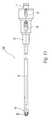
- FIG. 1Ais a perspective view from the distal left side of one embodiment of a reamer device according to the present invention.
- FIG. 1Bis a perspective view from the proximal right side of the device of FIG. 1 A.
- FIG. 2is a top view of the reamer device of FIGS. 1A and 1B.
- FIG. 3is a cross-sectional view of the device taken along line A—A of FIG. 2 .
- FIG. 4is a perspective view of one embodiment of a drive shaft assembly according to the present invention.
- FIG. 5is a side view of one embodiment of a reamer head according to the present invention.
- FIG. 6is a front view of the reamer head of FIG. 5 .
- FIG. 7is a rear view of the reamer head of FIG. 5 .
- FIG. 8is a front perspective view of the reamer head of FIG. 5 .
- FIG. 9is a rear perspective view of the reamer head of FIG. 5 .
- FIG. 10is an enlarged view of the side view of FIG. 5 .
- FIG. 11is an enlarged and partially fragmented perspective and cross-sectional view of the reamer shown in FIGS. 1A and 1B.
- FIG. 12shows an exemplary sample of a graph expressing a pressure-time curve of a system using the reamer of FIG. 1, the reamer head of FIG. 5, and the drive shaft assembly of FIG. 4 .
- FIG. 13is a perspective view of a portion of the drive shaft assembly of FIG. 4 with a guide wire inserted in the cannulation of the drive shaft.
- FIG. 14is a cross-sectional view of the drive shaft assembly taken along line A—A of FIG. 13 .
- FIG. 15is a top view of another embodiment of a reamer device according to the present invention.
- FIG. 16is a front perspective view of another embodiment of a reamer head according to the present invention.
- FIG. 17is an enlarged view of the side view of the reamer head of FIG. 16 .
- a first embodiment of a reamer 10comprises a reamer head 20 located at a distal end of reamer 10 for reaming a medullary canal, a flexible aspiration tube 13 for suction and removal of the emulsified bone and other material generated by reamer head 20 , a reamer head retainer 14 for retaining reamer head 20 on aspiration tube 13 while still allowing rotation of reamer head 20 with respect to aspiration tube 13 , and a manifold assembly 12 at a proximal end of reamer 10 .
- distaldesignates the end or direction near reamer head 20 and toward the front of reamer 10
- proximaldesignates the end or direction near manifold assembly 12 and toward the rear of reamer 10
- longitudinaldesignates an axis central to aspiration tube 13 .
- Aspiration tube 13is flexible so that it can bend to accommodate curvature of the bone and is preferably made of a translucent material so that the aspirated material can be observed.
- Manifold assembly 12has an irrigation port 15 and an aspiration port 16 for connecting to an irrigation source and aspiration means respectively.
- a drive shaft coupling 17is located at the proximal end of manifold assembly 12 . Drive shaft coupling 17 can be readily attached and detached to a drive shaft or some other means for rotating reamer head 20 .
- FIG. 4shows a drive shaft assembly 100 that can be used with reamer 10 to rotate reamer head 20 at sufficient speeds to ream the medullary canal.
- a drive shaft assembly 100 with reamer 10or any modular system in which the driving means is contained in a unit that is independent from the reamer) allows drive shaft assembly 100 to be reused with many different reamers.
- Such modularityis advantageous because different patients and clinical conditions will require different sized reamer heads.
- the reamer head, and not the drive meansexperiences the wear and abrasion of cutting bone.
- reamer 10can be a single-use, disposable item and drive shaft assembly 100 can be used for an extended period.
- Drive shaft assembly 100includes a flexible drive shaft 102 having a reamer head connector 104 on the distal end for releasably engaging reamer head 20 so that reamer head 20 rotates when flexible drive shaft 102 rotates, a power source connector 106 for connection to a source of power to initiate the rotation of drive shaft 102 , and a manifold coupling 108 located between reamer head and power source connectors 104 , 106 for engaging drive shaft coupling 17 .
- Drive shaft 102is sized to fit within the lumen of aspiration tube 13 .
- drive shaft 102is flexible to conform to any curvature of the bone being reamed.
- Drive shaft 102has a cannulation 110 for accommodating a guide wire 120 .
- Drive shaft 102has an opening 126 that extends from the outer surface of drive shaft 102 to cannulation 110 . Opening 126 is positioned on drive shaft 102 so that when drive shaft assembly 100 is coupled to reamer device 10 , opening 126 is in fluid communication with irrigation port 15 to allow irrigation to flow through cannulation 110 . Opening 126 has curved walls 128 , 130 . Curved wall 128 bows out to have a convex profile and curved wall 130 curves inward to have a concave profile. The curvature of curved walls 128 , 130 helps to draw water into cannulation 110 as drive shaft 102 rotates (which with respect to FIG. 14 is in the counter-clockwise direction).
- any suitable means for releasably joining manifold coupling 108 and drive shaft coupling 17can be used.
- a quick connect mechanismis used for rapid coupling and uncoupling.
- manifold coupling 108can have a spring loaded latch mechanism, such as ball bearings, which engage a groove in drive shaft coupling 17 .
- any suitable power source and means for securing drive shaft assembly 100 to the power sourcecan be used.
- the power sourceis preferably an air drive such as the Compact Air Drive available from Synthes (U.S.A.) of Paoli, Pa.
- Scaling means 34 and sleeve bearing 31define an irrigation chamber 35 and provide a hermetic seal to prevent irrigation fluid from escaping irrigation chamber 35 into aspiration port 16 or out the proximal end of reamer device 10 during operation.
- sleeve bearing 31prevents the aspirated emulsified material from entering irrigation chamber 35 .
- Reamer head 20is positioned coaxially within reamer head retainer 14 at the distal end of aspiration tube 13 .
- FIG. 15shows a reamer 210 that has a head retainer 14 ′ with a generally spherical outer profile shape.
- head retainer 14 ′follows reamer head 20
- the shape of head retainer 14 ′allows head retainer 14 ′ to glance off of the medullary canal walls should flexing occur with aspiration tube 13 with respect to drive shaft 102 .
- head retainer 14 ′can move smoothly while advancing through the medullary canal, retracting after reaming, and negotiating the fracture site.
- Reamer head 20is preferably made of a stainless steel, although any metallic, polymeric, ceramic, or composite material suitable for cutting bone can be used.
- a reamer cannulation 22extends from the distal tip to the proximal end of reamer head 20 (FIGS. 7 and 8 ). Reamer cannulation 22 is aligned with cannulation 110 of drive shaft 102 so that a guide wire can extend from the proximal end of drive shaft 102 through the distal end of reamer head 20 .
- reamer head 20consists of a cutting head 40 integral with a tubular shank 25 .
- the periphery of tubular shank 25is cylindrical and has a retaining groove 26 indented around the periphery which accommodates an extension from the inside of reamer head retainer 14 and permits reamer head 20 to rotate while maintaining a fixed location longitudinally at the distal end of the aspiration tube 13 .
- Tubular shank 25has a drive shaft receptor 23 at the proximal end which is configured to accommodate reamer head connector 104 of drive shaft 102 so that reamer head 20 must rotate when drive shaft 102 rotates.
- drive shaft receptor 22can be of any shape conforming to the exterior profile of reamer head connector 104 , it is preferably a female hex feature.
- Cutting head 40 of reamer head 20has a plurality of blades 41 , preferably at least five in number, extending radially outwardly from reamer cannulation 22 to form a substantially helical pattern. Correlating the number of blades to the particular blade geometry and rotation speed is advantageous in order to allow for appropriate amount of bone material to be removed while providing efficient cutting. When too many blades are used with a given blade shape, the flutes become very shallow and less bone material can be removed as a result. When an insufficient number of blades is used, the reamer head is not efficient in cutting bone tissue. In fact, the reamer head may bind or jam while cutting bone matter.
- Each blade 41has a multiple surfaced angular distal end with a straight front cutting edge 42 joined to a helical side cutting edge 44 .
- Front cutting edge 42is defined by the intersection between an inner blade wall 45 and a planar first lip surface 51 .
- the angle between inner blade wall 45 and first lip surface 51is acute.
- a planar second lip surface 52intersects first lip surface 51 at an obtuse angle to form a first lip edge 56 .
- a planar third lip surface 53intersects second lip surface 52 at an obtuse angle to form a trailing lip edge 58 .
- Side cutting edge 44is defined by the intersection between inner blade wall 45 and an outer blade surface 46 and is at a constant radial distance from the longitudinal axis and extends longitudinally in a helical fashion.
- Outer blade surface 46whorls radially inward from side cutting edge 44 along an arc toward an inner blade wall of an adjacent blade. The space between such adjacent blades defines a flute 43 which, during operation, functions to funnel the cut medullary canal material towards the proximal end of reamer head 20 for removal from the bone cavity through aspiration tube 13 under vacuum.
- Inner blade wall 45 and outer blade surface 46extend longitudinally on cutting head 40 terminating at the proximal end in a shoulder surface 48 . Shoulder surface 48 abuts tubular shank 25 .
- FIGS. 16 and 17show another embodiment of a reamer head 20 ′ according to the present invention.
- Reamer head 20 ′does not have any side cutting edges, thereby substantially minimizing the risk of laterally reaming through the cortex of the bone.
- Each blade 41has a multiple surfaced angular distal end with a straight front cutting edge 42 .
- Front cutting edge 42is defined by the intersection between an inner blade wall 45 and a planar first lip surface 51 . The angle between inner blade wall 45 and first lip surface 51 is acute.
- a planar second lip surface 52intersects first lip surface 51 at an obtuse angle to form a first lip edge 56 .
- Outer blade surface 46whorls radially inward along an arc toward an inner blade wall of an adjacent blade. The space between such adjacent blades defines a flute 43 which, during operation, functions to funnel the cut medullary canal material towards the proximal end of reamer head 20 ′ for removal from the bone cavity through aspiration tube 13 under vacuum.
- reamer 10which can be during open surgical, percutaneous, or any other minimally invasive procedure, will now be described referring primarily to FIG. 11 .
- the use of reamer 210is analogous to the use of reamer 10 , the primary difference between reamer 10 and reamer 210 being the different geometries of head retainer 14 shown in FIG. 2 and head retainer 14 ′ shown in FIG. 15 .
- guide wire 120is inserted into medullary canal 122 of bone 124 .
- the insertion of guide wire 120is typically done using fluoroscopy to ensure proper placement of guide wire 120 .
- Reamer 10with an appropriate cutter (such as reamer head 20 or 20 ′) attached and coupled with drive shaft 100 , is then placed over guide wire 120 so that guide wire 120 passes completely through aspiration tube 13 and provides a track which reamer 10 follows as it reams canal 122 .
- reamer 10 coupled with drive shaft 100has been connected to a driving means prior to insertion into medullary canal 122 .
- guide wire 120actually passes through cannulation 110 of drive shaft 102 and cannulation 22 of reamer head 20 .
- a preferable irrigation sourcewhich delivers the irrigation fluid at a sufficient rate and pressure, is a normal saline bag suspended one meter above irrigation port 15 . It should also be noted that, in addition to a saline bag, any biological compatible solution and delivery system can be used as the irrigation source.
- the irrigation fluidpasses from the irrigation source into irrigation port 15 and enters irrigation chamber 35 .
- the irrigation fluidtraveling along the path indicated by arrows I, flows through cannulation 110 in the space between the inner wall of cannulation and guide wire 120 and out of reamer head 20 .
- the aspirationalleviates intramedullary pressure and helps to remove emulsified material from reamer head 20 .
- the removal of materialnot only improves reaming, but also provides for the possibility of harvesting the emulsified material for grafting purposes.
- Suction created by an aspiration sourcetravels along the path indicated by arrows A.
- the irrigation fluidhelps to channel the emulsified material generated by reamer head 20 through flutes 43 and into the space between the outer wall of drive shaft 102 and the inner wall of aspiration tube 13 to transport the emulsified material from reamer head 20 through head retainer 14 , aspiration tube 13 , and aspiration port 16 and into a suitable container.
- a significant advantage of the system that includes reamer 10 , 210 , reamer head 20 , and drive shaft assembly 100is the ability to ream the medullary canal to the desired diameter in one pass, i.e. without the need to use multiple reaming heads of gradually increasing diameter until the desired reamed size is achieved.
- supplying irrigation to reamer head 20 while simultaneously providing aspiration, and using a reamer head with an efficient front cutting geometry (an optionally a side cutting geometry)produces less pressure and heat than prior art reaming devices.
- FIG. 12shows an exemplary sample of a graph expressing a pressure-time curve of the system according to the present invention in an animal model.
- Region Ishows that no increase in pressure is induced when an access opening to the medullary canal is made.
- the increase in pressure in Region IIresults from standard techniques to gain access to the medullary canal.
- Region IIIshows that no increase in pressure is induced when the guide wire is inserted.
- the present inventionreduces or eliminates intramedullary pressure. Specifically, the combined reaming, irrigating and aspirating functions to decrease intramedullary pressure below 100 mm Hg. In fact, as shown in Region IV, a negative intramedullary pressure is achieved with the system according to the present invention.
- the biologic threshold in the medullary canal for fat emboli and pulmonary emboliis known to be greater than or equal to 200 mm Hg, the incidence of fat and pulmonary emboli is reduced. Additionally, heat necrosis of the cortex is also eliminated due to the cooling caused by the flow of fluid during the process.
- FIG. 12shows another important advantage of the system according to the present invention.
- the medullary canal reaming(Region IV) requires approximately 50 seconds.
- conventional reaming in the same animal modelrequires approximately 500 seconds. This decrease in reaming time by a factor of ten means that reaming in clinical situations can be reduced from 30 minutes to 3 minutes. Thus, operating times (and costs) can be significantly reduced without any increased risks.
Landscapes
- Health & Medical Sciences (AREA)
- Surgery (AREA)
- Life Sciences & Earth Sciences (AREA)
- Biomedical Technology (AREA)
- Medical Informatics (AREA)
- Orthopedic Medicine & Surgery (AREA)
- Oral & Maxillofacial Surgery (AREA)
- Engineering & Computer Science (AREA)
- Dentistry (AREA)
- Heart & Thoracic Surgery (AREA)
- Nuclear Medicine, Radiotherapy & Molecular Imaging (AREA)
- Molecular Biology (AREA)
- Animal Behavior & Ethology (AREA)
- General Health & Medical Sciences (AREA)
- Public Health (AREA)
- Veterinary Medicine (AREA)
- Surgical Instruments (AREA)
- Materials For Medical Uses (AREA)
- Pharmaceuticals Containing Other Organic And Inorganic Compounds (AREA)
Abstract
Description
Priority of Provisional Application No. 60/118,485 filed Feb. 3, 1999 is claimed under 35 U.S.C. §119(e).
The present invention is directed to a device and method for bone tissue removal, and in particular to a device and method for expedited reaming of a medullary canal.
A wide variety of devices for cutting and removing bone tissue are known in the air. Examples of such include those described in U.S. Pat. No. 5,269,785 issued to Bonutti, U.S. Pat. No. 4,830,000 to Shutt, and U.S. Pat. No. 5,190,548 to Davis. In general, these and similar devices utilize a rotating cutting tip similar to a drill displaced at the distal end of drive shaft. Bone cutting devices for use in reaming the medullary canal typically use a flexible drive shaft because the medullary canals of bones are seldom straight and usually will have some degree of curvature. Most reamers also have a central bore through both the reamer and the drive shaft. The central bore is intended to receive a long, small diameter guide pin or wire which is initially inserted into the medullary canal to act as a track for the advancing reamer.
Reamers are used in orthopedic surgery to prepare the medullary canals of bone for a wide variety of surgical procedures. Such procedures include total hip and knee replacement, nail insertion to stabilize a long bone fracture, an intramedullary osteotomy, and bone harvesting for grafting purposes.
From both a mechanical and a biological point of view, medullary reaming is particularly beneficial in improving the performance of implants. Specifically, reaming expands the medullary canal so that larger diameter implants can be inserted. These larger diameter implants are less likely to fail. In fact, certain fractures require over-reaming so that larger implants can be used. Without reaming, the surgeon must use a “best guess” estimate when selecting the diameter of the implant. The medical literature contains numerous case studies reporting the adverse consequences of an inaccurate estimate. Reaming provides a direct measurement of the diameter of the medullary canal, and thereby allows for the selection of an implant that precisely fills the canal. As a result, the stability of the fracture site is enhanced by achieving endosteal contact. When implants do not fill the medullary canal, load sharing between the implant and the bone is decreased. This increases the load that is transferred to the implant and promotes both implant failure and stress shielding of the bone.
Despite such benefits, negative consequences have also been associated with medullary reaming. In particular, current procedures for reaming the medullary cavity can result in an increase in both temperature and pressure. Like any process in which material is being removed, reaming causes generation of heat. Furthermore, a hydraulic pressure, which far exceeds that of blood pressure, builds up in the cavity during reaming. The reamer acts as a hydraulic piston within the bone cavity, and if the contents of the canal, which include a mixture of medullary fat, blood, blood clots, and bone debris, enter the blood stream, an embolism can result. Excessive heat has been associated with an increased incidence of aseptic necrosis of the cortex and elevated pressure has been associated with an increased risk of fat emboli. These complications are more likely to occur in patients when extenuating factors such as shock, existing lung contusion, multiple traumas, or pre-existing pulmonary impairment are present. In these situations, the preferred method of reaming would usually not be performed due to the increased risks involved.
Various devices and methods exist for reducing the intramedullary pressure build-up during reaming. For example, in prosthetic joint replacement, a distal venting hole, a large insertion hole, and a modified technique for cement insertion have all been shown to have some success ill reducing pressure, and presumably, the chance of fat embolism. Venting holes in the bone only have little effect because their diameter is typically too small and local peak values must be assumed during the passage of the reamer. Similarly, reaming the medullary cavity less does not prevent pressure increase. In fact, pressure can be high even for reamers of small diameter.
Another technique which has been used in an attempt to reduce temperature and pressure is to perform the reaming in multiple steps with increasing size of reamers with each step. As a result, reaming procedures are done slowly with the application of gentle pressure and requiring multiple passes. Usually reaming is performed in 1 mm diameter increments until the bone cortex is reached and then in 0.5 mm increments thereafter. In this regard, the reaming is carried out with less compression force and the intramedullary pressure can be easily reduced with most reaming devices utilizing this slow process. A faster reaming process utilizing fewer passes would be desirable in order to reduce operating time and medical costs.
Another disadvantage associated with current devices and methods is the reuse of reamers. Because current methods involve the use of multiple reamers of variable sizes to create one large opening in the medullary canal, reamers are usually reused in subsequent bone reaming procedures. As a result, reamers may become blunt over time and their continued use can produce greater intramedullary pressures and a greater increase in cortical temperature. Consequently, the careful attention of surgeons and operating staff to treat the reamers gently and replace them whenever necessary is trying and costly. A single use device is desirable to avoid the problems associated with the dulling of reamers which occurs with time.
Another disadvantage of current devices is due to the use of reamer designs with shallow flutes and large shafts. It has been shown that reamers with small shafts and deep flutes are more beneficial in reducing intramedullary pressure and temperature.
Thus, there exists a need for a device and method for reaming a medullary canal at an enhanced rate without increasing the risk of fat emboli and heat necrosis upon cutting and removal of bone tissue.
The present invention relates to a device for reaming a medullary canal of a bone. The device includes a rotatable drive shaft connected at the proximal end to a rotational drive element and a reamer head rotatably coupled to the distal end of the drive shaft. The reamer head has a tubular shank engaging the distal end of the drive shaft and a cutting head integral with the shank and having a plurality of blades. Flutes are located between adjacent blades. At least some and preferable all of the blades have a front cutting portion that includes at least two planar surfaces. A helical side cutting portion may be added to any or all of the blades. Preferably, there are at least five blades and each blade has at least three planar surfaces.
In one embodiment, each blade has a front cutting edge defined by the intersection between the inner blade wall and one of the planar surfaces. This front cutting edge may be oriented at an angle of approximately 30° to 45° with respect to the longitudinal axis of the tubular shank. In another embodiment, the helical side cutting portion further includes a side cutting edge defined by the intersection between the inner blade wall and the outer blade wall.
The drive shaft and reamer head each may have a cannulation. These two cannulations are aligned when the tubular shank is engaged with the drive shaft to form a center channel. One use for this channel is for receiving a guide wire that can be used to direct the device in the medullary canal.
The device may also include an aspiration tube for removing cut material generated by the reamer head. The aspiration tube has a manifold assembly at a proximal end, a reamer head retainer at a distal end, and a lumen configured and dimensioned to receive the drive shaft. Preferably, the center channel is in fluid communication with an irrigation source to provide irrigation to the cutting head. The manifold assembly may include an irrigation port connected to the irrigation source and an irrigation chamber in fluid communication with the irrigation port. The irrigation fluid travels from the irrigation chamber through an opening on the drive shaft and into the center channel. In one embodiment in which the reamer head is larger than the aspiration tube, the reamer head retainer has a substantially spherical outer profile.
The distal end of the lumen of the aspiration tube is in fluid communication with the flutes of the reamer head and the proximal end of the lumen is in fluid communication with a suction source. Preferably, the manifold assembly includes an aspiration port connected to the suction source to assist in the removal of the cut material.
The invention also relates to a method for removing tissue from a medullary canal of a bone. This method includes the steps of reaming an area of the medullary canal to remove the material; irrigating the material to be removed while reaming to reduce generation of heat and move removed material from the reaming area; and aspirating the removed material while reaming to create a negative intramedullary canal pressure to assist in the removal of the material.
The method may also include the step of inserting an implant in the medullary canal after the removal of material. Preferably, the reaming is done with a single reaming device, and the device may be guided to the appropriate location in the medullary canal using a guide wire which passes through a cannulation in the device. In another embodiment, the method includes the step of harvesting the removed tissue for use as a graft.
Preferred features of the present invention are disclosed in the accompanying drawings, wherein similar reference characters denote similar elements throughout the several views, and wherein:
FIG. 1A is a perspective view from the distal left side of one embodiment of a reamer device according to the present invention.
FIG. 1B is a perspective view from the proximal right side of the device of FIG.1A.
FIG. 2 is a top view of the reamer device of FIGS. 1A and 1B.
FIG. 3 is a cross-sectional view of the device taken along line A—A of FIG.2.
FIG. 4 is a perspective view of one embodiment of a drive shaft assembly according to the present invention.
FIG. 5 is a side view of one embodiment of a reamer head according to the present invention.
FIG. 6 is a front view of the reamer head of FIG.5.
FIG. 7 is a rear view of the reamer head of FIG.5.
FIG. 8 is a front perspective view of the reamer head of FIG.5.
FIG. 9 is a rear perspective view of the reamer head of FIG.5.
FIG. 10 is an enlarged view of the side view of FIG.5.
FIG. 11 is an enlarged and partially fragmented perspective and cross-sectional view of the reamer shown in FIGS. 1A and 1B.
FIG. 12 shows an exemplary sample of a graph expressing a pressure-time curve of a system using the reamer of FIG. 1, the reamer head of FIG. 5, and the drive shaft assembly of FIG.4.
FIG. 13 is a perspective view of a portion of the drive shaft assembly of FIG. 4 with a guide wire inserted in the cannulation of the drive shaft.
FIG. 14 is a cross-sectional view of the drive shaft assembly taken along line A—A of FIG.13.
FIG. 15 is a top view of another embodiment of a reamer device according to the present invention.
FIG. 16 is a front perspective view of another embodiment of a reamer head according to the present invention.
FIG. 17 is an enlarged view of the side view of the reamer head of FIG.16.
For convenience, the same or equivalent elements in the various embodiments of the invention illustrated in the drawings have been identified with the same reference numerals. Further, in the description that follows, any reference to either orientation or direction is intended primarily for the convenience of description and is not intended in any way to limit the scope of the present invention thereto.
Referring to FIGS. 1-3, a first embodiment of areamer 10 according to the present invention comprises areamer head 20 located at a distal end ofreamer 10 for reaming a medullary canal, aflexible aspiration tube 13 for suction and removal of the emulsified bone and other material generated byreamer head 20, areamer head retainer 14 for retainingreamer head 20 onaspiration tube 13 while still allowing rotation ofreamer head 20 with respect toaspiration tube 13, and amanifold assembly 12 at a proximal end ofreamer 10. Thus, as used in this application, the term distal designates the end or direction nearreamer head 20 and toward the front ofreamer 10, and the term proximal designates the end or direction nearmanifold assembly 12 and toward the rear ofreamer 10. The term longitudinal designates an axis central toaspiration tube 13.
FIG. 4 shows adrive shaft assembly 100 that can be used withreamer 10 to rotatereamer head 20 at sufficient speeds to ream the medullary canal. The use of adrive shaft assembly 100 with reamer10 (or any modular system in which the driving means is contained in a unit that is independent from the reamer) allowsdrive shaft assembly 100 to be reused with many different reamers. Such modularity is advantageous because different patients and clinical conditions will require different sized reamer heads. Furthermore, the reamer head, and not the drive means, experiences the wear and abrasion of cutting bone. Thus,reamer 10 can be a single-use, disposable item and driveshaft assembly 100 can be used for an extended period.
Driveshaft assembly 100 includes aflexible drive shaft 102 having areamer head connector 104 on the distal end for releasably engagingreamer head 20 so thatreamer head 20 rotates whenflexible drive shaft 102 rotates, apower source connector 106 for connection to a source of power to initiate the rotation ofdrive shaft 102, and amanifold coupling 108 located between reamer head andpower source connectors drive shaft coupling 17. Driveshaft 102 is sized to fit within the lumen ofaspiration tube 13. However, as will be described in more detail later, there is sufficient space between the outer wall ofdrive shaft 102 and the inner wall ofaspiration tube 13 to allow transport of aspirated material fromreamer head 20 throughaspiration tube 13 toaspiration port 16. As was the case foraspiration tube 13,drive shaft 102 is flexible to conform to any curvature of the bone being reamed. Driveshaft 102 has acannulation 110 for accommodating aguide wire 120.
As seen best in FIGS. 11,13, and14, there is sufficient space between the outer wall ofguide wire 120 and the inner wall ofcannulation 110 to allow transport of an irrigation fluid fromirrigation port 15 throughcannulation 110 toreamer head 20. Driveshaft 102 has anopening 126 that extends from the outer surface ofdrive shaft 102 tocannulation 110.Opening 126 is positioned ondrive shaft 102 so that whendrive shaft assembly 100 is coupled toreamer device 10, opening126 is in fluid communication withirrigation port 15 to allow irrigation to flow throughcannulation 110.Opening 126 hascurved walls Curved wall 128 bows out to have a convex profile andcurved wall 130 curves inward to have a concave profile. The curvature ofcurved walls cannulation 110 asdrive shaft 102 rotates (which with respect to FIG. 14 is in the counter-clockwise direction).
Any suitable means for releasably joiningmanifold coupling 108 and driveshaft coupling 17 can be used. Preferably, a quick connect mechanism is used for rapid coupling and uncoupling. For example,manifold coupling 108 can have a spring loaded latch mechanism, such as ball bearings, which engage a groove indrive shaft coupling 17. Similarly, any suitable power source and means for securingdrive shaft assembly 100 to the power source can be used. As pneumatic tools are widely used in orthopaedic surgery, the power source is preferably an air drive such as the Compact Air Drive available from Synthes (U.S.A.) of Paoli, Pa.
Referring back to FIG. 3, housed withinmanifold assembly 12 is a sealingelement 34 and asleeve bearing 31. Scaling means34 andsleeve bearing 31 define anirrigation chamber 35 and provide a hermetic seal to prevent irrigation fluid from escapingirrigation chamber 35 intoaspiration port 16 or out the proximal end ofreamer device 10 during operation. In addition,sleeve bearing 31 prevents the aspirated emulsified material from enteringirrigation chamber 35.
Although many different reamer heads can be used withreamer reamer head 20 consists of a cuttinghead 40 integral with atubular shank 25. The periphery oftubular shank 25 is cylindrical and has a retaininggroove 26 indented around the periphery which accommodates an extension from the inside ofreamer head retainer 14 and permitsreamer head 20 to rotate while maintaining a fixed location longitudinally at the distal end of theaspiration tube 13.Tubular shank 25 has adrive shaft receptor 23 at the proximal end which is configured to accommodatereamer head connector 104 ofdrive shaft 102 so thatreamer head 20 must rotate whendrive shaft 102 rotates. Althoughdrive shaft receptor 22 can be of any shape conforming to the exterior profile ofreamer head connector 104, it is preferably a female hex feature.
Cuttinghead 40 ofreamer head 20 has a plurality ofblades 41, preferably at least five in number, extending radially outwardly fromreamer cannulation 22 to form a substantially helical pattern. Correlating the number of blades to the particular blade geometry and rotation speed is advantageous in order to allow for appropriate amount of bone material to be removed while providing efficient cutting. When too many blades are used with a given blade shape, the flutes become very shallow and less bone material can be removed as a result. When an insufficient number of blades is used, the reamer head is not efficient in cutting bone tissue. In fact, the reamer head may bind or jam while cutting bone matter.
Eachblade 41 has a multiple surfaced angular distal end with a straightfront cutting edge 42 joined to a helicalside cutting edge 44.Front cutting edge 42 is defined by the intersection between aninner blade wall 45 and a planarfirst lip surface 51. The angle betweeninner blade wall 45 andfirst lip surface 51 is acute. A planarsecond lip surface 52 intersectsfirst lip surface 51 at an obtuse angle to form afirst lip edge 56. A planarthird lip surface 53 intersectssecond lip surface 52 at an obtuse angle to form a trailing lip edge58.Side cutting edge 44 is defined by the intersection betweeninner blade wall 45 and anouter blade surface 46 and is at a constant radial distance from the longitudinal axis and extends longitudinally in a helical fashion.Outer blade surface 46 whorls radially inward fromside cutting edge 44 along an arc toward an inner blade wall of an adjacent blade. The space between such adjacent blades defines aflute 43 which, during operation, functions to funnel the cut medullary canal material towards the proximal end ofreamer head 20 for removal from the bone cavity throughaspiration tube 13 under vacuum.Inner blade wall 45 andouter blade surface 46 extend longitudinally on cuttinghead 40 terminating at the proximal end in ashoulder surface 48.Shoulder surface 48 abutstubular shank 25.
FIGS. 16 and 17 show another embodiment of areamer head 20′ according to the present invention.Reamer head 20′ does not have any side cutting edges, thereby substantially minimizing the risk of laterally reaming through the cortex of the bone. Eachblade 41 has a multiple surfaced angular distal end with a straightfront cutting edge 42.Front cutting edge 42 is defined by the intersection between aninner blade wall 45 and a planarfirst lip surface 51. The angle betweeninner blade wall 45 andfirst lip surface 51 is acute. A planarsecond lip surface 52 intersectsfirst lip surface 51 at an obtuse angle to form afirst lip edge 56.Outer blade surface 46 whorls radially inward along an arc toward an inner blade wall of an adjacent blade. The space between such adjacent blades defines aflute 43 which, during operation, functions to funnel the cut medullary canal material towards the proximal end ofreamer head 20′ for removal from the bone cavity throughaspiration tube 13 under vacuum.
The use ofreamer 10, which can be during open surgical, percutaneous, or any other minimally invasive procedure, will now be described referring primarily to FIG.11. It should be noted that the use ofreamer 210 is analogous to the use ofreamer 10, the primary difference betweenreamer 10 andreamer 210 being the different geometries ofhead retainer 14 shown in FIG.2 andhead retainer 14′ shown in FIG.15. After the bone to be reamed has been accessed,guide wire 120 is inserted intomedullary canal 122 ofbone 124. The insertion ofguide wire 120 is typically done using fluoroscopy to ensure proper placement ofguide wire 120.Reamer 10, with an appropriate cutter (such asreamer head drive shaft 100, is then placed overguide wire 120 so thatguide wire 120 passes completely throughaspiration tube 13 and provides a track which reamer10 follows as itreams canal 122. Preferably,reamer 10 coupled withdrive shaft 100, has been connected to a driving means prior to insertion intomedullary canal 122. Thus,guide wire 120 actually passes throughcannulation 110 ofdrive shaft 102 andcannulation 22 ofreamer head 20.
While reamingmedullary canal 122, irrigation and aspiration are applied simultaneously. The irrigation substantially coolsreamer head 20,medullary canal 122, andbone 124. A preferable irrigation source, which delivers the irrigation fluid at a sufficient rate and pressure, is a normal saline bag suspended one meter aboveirrigation port 15. It should also be noted that, in addition to a saline bag, any biological compatible solution and delivery system can be used as the irrigation source. The irrigation fluid passes from the irrigation source intoirrigation port 15 and entersirrigation chamber 35. The irrigation fluid, traveling along the path indicated by arrows I, flows throughcannulation 110 in the space between the inner wall of cannulation andguide wire 120 and out ofreamer head 20.
The aspiration alleviates intramedullary pressure and helps to remove emulsified material fromreamer head 20. The removal of material not only improves reaming, but also provides for the possibility of harvesting the emulsified material for grafting purposes. Suction created by an aspiration source travels along the path indicated by arrows A. Specifically, the irrigation fluid helps to channel the emulsified material generated byreamer head 20 throughflutes 43 and into the space between the outer wall ofdrive shaft 102 and the inner wall ofaspiration tube 13 to transport the emulsified material fromreamer head 20 throughhead retainer 14,aspiration tube 13, andaspiration port 16 and into a suitable container.
A significant advantage of the system that includesreamer reamer head 20, and driveshaft assembly 100 is the ability to ream the medullary canal to the desired diameter in one pass, i.e. without the need to use multiple reaming heads of gradually increasing diameter until the desired reamed size is achieved. In this regard, supplying irrigation toreamer head 20 while simultaneously providing aspiration, and using a reamer head with an efficient front cutting geometry (an optionally a side cutting geometry) produces less pressure and heat than prior art reaming devices.
FIG. 12 shows an exemplary sample of a graph expressing a pressure-time curve of the system according to the present invention in an animal model. Region I shows that no increase in pressure is induced when an access opening to the medullary canal is made. The increase in pressure in Region II results from standard techniques to gain access to the medullary canal. Region III shows that no increase in pressure is induced when the guide wire is inserted. As opposed to standard reaming process, the present invention reduces or eliminates intramedullary pressure. Specifically, the combined reaming, irrigating and aspirating functions to decrease intramedullary pressure below 100 mm Hg. In fact, as shown in Region IV, a negative intramedullary pressure is achieved with the system according to the present invention. Because the biologic threshold in the medullary canal for fat emboli and pulmonary emboli is known to be greater than or equal to 200 mm Hg, the incidence of fat and pulmonary emboli is reduced. Additionally, heat necrosis of the cortex is also eliminated due to the cooling caused by the flow of fluid during the process.
FIG. 12 shows another important advantage of the system according to the present invention. Specifically, the medullary canal reaming (Region IV) requires approximately 50 seconds. In contrast, conventional reaming in the same animal model requires approximately 500 seconds. This decrease in reaming time by a factor of ten means that reaming in clinical situations can be reduced from 30 minutes to 3 minutes. Thus, operating times (and costs) can be significantly reduced without any increased risks.
While various descriptions of the present invention are described above, it should be understood that the various features can be used singly or in any combination thereof. Therefore, this invention is not to be limited to only the specifically preferred embodiments depicted herein.
Further, it should be understood that variations and modifications within the spirit and scope of the invention may occur to those skilled in the art to which the invention pertains. Accordingly, all expedient modifications readily attainable by one versed in the art from the disclosure set forth herein that are within the scope and spirit of the present invention are to be included as further embodiments of the present invention. The scope of the present invention is accordingly defined as set forth in the appended claims.
Claims (18)
1. A device for reaming a medullary canal of a bone comprising:
a rotatable drive shaft having proximal and distal ends and connected at a proximal end to a rotational drive element for causing rotation of the drive shaft; and
a reamer head coupled to the distal end of the drive shaft, said reamer head comprising:
a tubular shank having a longitudinal axis and engaging the distal end of the drive shaft; and
a cutting head integral with the shank and having a plurality of blades and flutes therebetween for cutting and reaming of bone;
wherein each blade has inner and outer blade walls, a front cutting portion and a helical side cutting portion, with the front cutting portion comprising at least two planar surfaces and a front cutting edge defined by an intersection between the inner blade wall and one of the planar surfaces.
2. The device according to claim1 wherein the front cutting edge is oriented at an angle from about 30° to about 45° with respect to the longitudinal axis of the tubular shank.
3. The device according to claim1 wherein the helical side cutting portion further comprises a side cutting edge defined by an intersection between the inner blade wall and the outer blade wall.
4. The device according to claim1 wherein the front cutting portion includes at least three planar surfaces.
5. The device of claim1 wherein the cutting head has at least five blades.
6. The device of claim1 wherein the drive shaft and reamer head each has a cannulation, with the drive shaft cannulation aligning with the reamer head cannulation when the tubular shank is engaged with the drive shaft to form a center channel through the device.
7. A device for reaming a medullary canal of a bone comprising:
a rotatable drive shaft having proximal and distal ends and connected at a proximal end to a rotational drive element for causing rotation of the drive shaft;
a reamer head coupled to the distal end of the drive shaft, said reamer head comprising:
a tubular shank having a longitudinal axis and engaging the distal end of the drive shaft; and
a cutting head integral with the shank and having a plurality of blades and flutes therebetween for cutting and reaming of bone; and
an aspiration tube for removing cut material generated by the reamer head, the aspiration tube having a manifold assembly at a proximal end, a reamer head retainer at a distal end, and a lumen configured and dimensioned to receive the drive shaft,
wherein at least some of the blades have a front cutting portion with at least two planar surfaces and
wherein the drive shaft and reamer head each has a cannulation, with the drive shaft cannulation aligning with the reamer head cannulation when the tubular shank is engaged with the drive shaft to form a center channel through the device.
8. The device of claim7 wherein the center channel is in fluid communication with an irrigation source to provide irrigation to the cutting head to assist in the removal of the cut material.
9. The device of claim8 wherein:
the manifold assembly includes an irrigation port connectable to the irrigation source and an irrigation chamber in fluid communication with the irrigation port; and
the drive shaft has an opening extending from an outer surface of the drive shaft to the drive shaft cannulation and located within the irrigation chamber.
10. The device of claim9 wherein the drive shaft opening has curved walls to draw irrigation into the center channel from the irrigation chamber as the drive shaft rotates.
11. The device of claim7 wherein the lumen of the aspiration tube is in fluid communication with the plurality of flutes at the distal end and is in fluid communication with a suction source at the proximal end.
12. The device of claim11 wherein the manifold assembly includes an aspiration port connectable to the suction source.
13. The device of claim7 wherein the reamer head retainer has a substantially spherical outer profile.
14. A method for removing material from a medullary canal of a bone comprising the steps of:
reaming an area of the medullary canal with the device of claim8 to remove the material;
irrigating the material to be removed while reaming to reduce generation of heat and move removed material from the reaming area; and
aspirating the removed material while reaming to create a negative intramedullary canal pressure to assist in the removal of the material.
15. The method of claim14 further comprising the step of inserting an implant in the medullary canal after the removal of material.
16. The method of claim14 wherein the reaming is done with a single reaming device to reduce reaming time.
17. The method of claim16 which further comprises guiding the reaming device into the medullary canal using a guide wire which passes through a cannulation in the reaming device.
18. The method of claim14 further comprising the step of harvesting the removed material for future use.
Priority Applications (1)
| Application Number | Priority Date | Filing Date | Title |
|---|---|---|---|
| US09/495,932US6332886B1 (en) | 1999-02-03 | 2000-02-02 | Surgical reamer and method of using same |
Applications Claiming Priority (2)
| Application Number | Priority Date | Filing Date | Title |
|---|---|---|---|
| US11848599P | 1999-02-03 | 1999-02-03 | |
| US09/495,932US6332886B1 (en) | 1999-02-03 | 2000-02-02 | Surgical reamer and method of using same |
Publications (1)
| Publication Number | Publication Date |
|---|---|
| US6332886B1true US6332886B1 (en) | 2001-12-25 |
Family
ID=22378892
Family Applications (1)
| Application Number | Title | Priority Date | Filing Date |
|---|---|---|---|
| US09/495,932Expired - LifetimeUS6332886B1 (en) | 1999-02-03 | 2000-02-02 | Surgical reamer and method of using same |
Country Status (13)
| Country | Link |
|---|---|
| US (1) | US6332886B1 (en) |
| EP (1) | EP1148825B1 (en) |
| JP (1) | JP4632546B2 (en) |
| KR (1) | KR100773964B1 (en) |
| CN (1) | CN1261080C (en) |
| AT (1) | ATE290825T1 (en) |
| AU (1) | AU747156B2 (en) |
| CA (1) | CA2360867C (en) |
| DE (1) | DE60018712T2 (en) |
| ES (1) | ES2235828T3 (en) |
| NZ (1) | NZ512331A (en) |
| TW (1) | TW427896B (en) |
| WO (1) | WO2000045714A1 (en) |
Cited By (132)
| Publication number | Priority date | Publication date | Assignee | Title |
|---|---|---|---|---|
| WO2003045257A2 (en) | 2001-11-21 | 2003-06-05 | Synthes (U.S.A.) | Attachable/detachable reamer head for surgical reamer |
| US20030163136A1 (en)* | 2000-04-05 | 2003-08-28 | Alexander Joist | Device for treating human and/or animal tissue |
| US20040006358A1 (en)* | 2000-04-05 | 2004-01-08 | Pathway Medical Technologies, Inc. | Intralumenal material removal using a cutting device for differential cutting |
| US20040111093A1 (en)* | 2002-12-02 | 2004-06-10 | Chappuis James L. | Facet fusion system |
| US20040122437A1 (en)* | 2002-12-20 | 2004-06-24 | Dwyer Kimberly A. | Alignment device for modular implants and method |
| US20040122440A1 (en)* | 2002-12-20 | 2004-06-24 | Daniels David W. | Instrument and associated method of trialing for modular hip stems |
| US20040122439A1 (en)* | 2002-12-20 | 2004-06-24 | Dwyer Kimberly A. | Adjustable biomechanical templating & resection instrument and associated method |
| US20040167529A1 (en)* | 2003-02-24 | 2004-08-26 | Six-O, Ltd. | Device and method for collecting surgical material |
| US20040191897A1 (en)* | 2003-03-31 | 2004-09-30 | The Cleveland Clinic Foundation | Apparatus and method for harvesting bone marrow |
| US20040267267A1 (en)* | 2003-06-25 | 2004-12-30 | Daniels David Wayne | Non-linear reamer for bone preparation and associated method |
| US20060004371A1 (en)* | 2004-07-01 | 2006-01-05 | Howmedica Osteonics Corp. | Orthopedic reamer |
| US20060111724A1 (en)* | 2004-11-24 | 2006-05-25 | Yeung Research | Bone harvesting drill bit for oral surgery |
| US20060129159A1 (en)* | 2002-06-29 | 2006-06-15 | Hee-Young Lee | Facial bone contouring device using hollowed rasp provided with non-plugging holes formed through cutting plane |
| US7074224B2 (en) | 2003-06-25 | 2006-07-11 | Depuy Products, Inc. | Modular tapered reamer for bone preparation and associated method |
| FR2883156A1 (en)* | 2005-03-15 | 2006-09-22 | Jean Claude Yeung | Bone boring and recuperation drill for e.g. dental implantology, has blades permitting to recuperate bone, other blades permitting progression of drill in bone and bone recuperation cavities found along the blades |
| US20060235431A1 (en)* | 2005-04-15 | 2006-10-19 | Cook Vascular Incorporated | Lead extraction device |
| US20070050028A1 (en)* | 2005-08-26 | 2007-03-01 | Conner E S | Spinal implants and methods of providing dynamic stability to the spine |
| US7235106B2 (en) | 2002-12-20 | 2007-06-26 | Depuy Products, Inc. | Modular hip stems and associated method of trialing |
| USD549344S1 (en)* | 2003-01-16 | 2007-08-21 | Concept Matrix, Llc | Diskectomy tool with convex head |
| WO2007104837A1 (en)* | 2006-03-16 | 2007-09-20 | Jean-Claude Yeung | Bone-reaming drill with multiple blades |
| US7297166B2 (en) | 2003-06-25 | 2007-11-20 | Depuy Products, Inc. | Assembly tool for modular implants and associated method |
| US20070270771A1 (en)* | 2006-04-24 | 2007-11-22 | Ralph James D | Autologous bone harvest during osteotomy and bone drilling procedures |
| US20070276393A1 (en)* | 2003-11-28 | 2007-11-29 | Lucia Bonadei | Surgical Reamer and Blades for Said Reamer |
| US20070276401A1 (en)* | 2006-05-23 | 2007-11-29 | Choe Simon H | Instrumentation for fixation devices |
| US20070298376A1 (en)* | 2006-06-27 | 2007-12-27 | Straumann Holding Ag | Bur for dental implantology |
| US20080071341A1 (en)* | 2005-04-15 | 2008-03-20 | Cook Vascular Incorporated | Tip for lead extraction device |
| US20080108999A1 (en)* | 2000-06-24 | 2008-05-08 | Yves Desarzens | Guided reamer system for reshaping bone |
| US20080111101A1 (en)* | 2006-11-09 | 2008-05-15 | Jason Keleher | Compositions and methods for CMP of low-k-dielectric materials |
| US20080195104A1 (en)* | 2007-02-09 | 2008-08-14 | Sidebotham Christopher G | Modular tapered hollow reamer for medical applications |
| US20080195106A1 (en)* | 2007-02-09 | 2008-08-14 | Sidebotham Christopher G | Modular spherical hollow reamer assembly for medical applications |
| US20080195103A1 (en)* | 2007-02-09 | 2008-08-14 | Lawis Randall J | Hollow reamer for medical applications |
| US20080195105A1 (en)* | 2007-02-09 | 2008-08-14 | Sidebotham Christopher G | Low cost modular tapered hollow reamer for medical applications |
| WO2008064347A3 (en)* | 2006-11-22 | 2008-12-04 | Sonoma Orthopedic Products Inc | Curved orthopedic tool |
| US20080306483A1 (en)* | 2007-06-07 | 2008-12-11 | Iannarone Ronald C | Retrograde cutting instrument |
| USD595850S1 (en)* | 2007-02-09 | 2009-07-07 | Gebr. Brasseler Gmbh & Co. Kg | Dental instrument |
| US20090208902A1 (en)* | 2008-02-20 | 2009-08-20 | Gebr. Brasseler Gmbh & Co. Kg | Dental drill made of plastics |
| US7582092B2 (en) | 2003-06-25 | 2009-09-01 | Depuy Products, Inc. | Assembly tool for modular implants and associated method |
| USD610259S1 (en) | 2008-10-23 | 2010-02-16 | Vertos Medical, Inc. | Tissue modification device |
| USD611146S1 (en) | 2008-10-23 | 2010-03-02 | Vertos Medical, Inc. | Tissue modification device |
| US20100063507A1 (en)* | 2007-02-09 | 2010-03-11 | Sidebotham Christopher G | Low cost modular tapered and spherical hollow reamers for medical applications |
| US20100069907A1 (en)* | 2007-02-09 | 2010-03-18 | Sidebotham Christopher G | Modular tapered hollow reamer for medical applications |
| WO2010066221A1 (en)* | 2008-12-10 | 2010-06-17 | Gottfried Wilhelm Leibniz Universität Hannover | Drilling method, drilling machine intended for surgical purposes having an attachment, and attachment for a drilling machine intended for surgical purposes |
| US20100167235A1 (en)* | 2006-09-25 | 2010-07-01 | Piezosurgery S.R.L. | Handpiece with surgical tool to perform holes in bone tissues |
| USD619253S1 (en) | 2008-10-23 | 2010-07-06 | Vertos Medical, Inc. | Tissue modification device |
| USD619252S1 (en) | 2008-10-23 | 2010-07-06 | Vertos Medical, Inc. | Tissue modification device |
| USD621939S1 (en) | 2008-10-23 | 2010-08-17 | Vertos Medical, Inc. | Tissue modification device |
| DE202009006792U1 (en)* | 2009-05-12 | 2010-09-23 | Joimax Gmbh | Spinal cutter |
| US20100286696A1 (en)* | 2003-12-30 | 2010-11-11 | Depuy Products, Inc. | Minimally Invasive Bone Miller Apparatus |
| US7846162B2 (en) | 2005-05-18 | 2010-12-07 | Sonoma Orthopedic Products, Inc. | Minimally invasive actuable bone fixation devices |
| US7896879B2 (en) | 2004-07-29 | 2011-03-01 | Vertos Medical, Inc. | Spinal ligament modification |
| US7909825B2 (en) | 2006-11-22 | 2011-03-22 | Sonoma Orthepedic Products, Inc. | Fracture fixation device, tools and methods |
| USD635671S1 (en) | 2008-10-23 | 2011-04-05 | Vertos Medical, Inc. | Tissue modification device |
| US7942830B2 (en) | 2006-05-09 | 2011-05-17 | Vertos Medical, Inc. | Ipsilateral approach to minimally invasive ligament decompression procedure |
| US20110208194A1 (en)* | 2009-08-20 | 2011-08-25 | Howmedica Osteonics Corp. | Flexible acl instrumentation, kit and method |
| US8167882B2 (en) | 2008-09-30 | 2012-05-01 | Depuy Products, Inc. | Minimally invasive bone miller apparatus |
| US8287541B2 (en) | 2005-05-18 | 2012-10-16 | Sonoma Orthopedic Products, Inc. | Fracture fixation device, tools and methods |
| US8287538B2 (en) | 2008-01-14 | 2012-10-16 | Conventus Orthopaedics, Inc. | Apparatus and methods for fracture repair |
| US8518050B2 (en) | 2007-10-31 | 2013-08-27 | DePuy Synthes Products, LLC | Modular taper assembly device |
| US8597298B2 (en) | 2006-09-29 | 2013-12-03 | DePuy Synthes Products, LLC | Proximal reamer |
| US8696671B2 (en) | 2005-07-29 | 2014-04-15 | Vertos Medical Inc. | Percutaneous tissue excision devices |
| US20140236156A1 (en)* | 2011-09-16 | 2014-08-21 | CHIRMAT Sàrl | Surgical tool for reaming the diaphyseal canal of long bones |
| US20140257112A1 (en)* | 2013-03-07 | 2014-09-11 | Marc Evan Siegel | Gynecological scope and morcellation systems and devices |
| US20140276844A1 (en)* | 2013-03-12 | 2014-09-18 | Smith & Nephew, Inc. | Retro guidewire reamer |
| US8906022B2 (en) | 2010-03-08 | 2014-12-09 | Conventus Orthopaedics, Inc. | Apparatus and methods for securing a bone implant |
| DE102013211594A1 (en)* | 2013-06-20 | 2014-12-24 | Martin Geisinger | Bone chip mill |
| US8961516B2 (en) | 2005-05-18 | 2015-02-24 | Sonoma Orthopedic Products, Inc. | Straight intramedullary fracture fixation devices and methods |
| US8961518B2 (en) | 2010-01-20 | 2015-02-24 | Conventus Orthopaedics, Inc. | Apparatus and methods for bone access and cavity preparation |
| US8998919B2 (en) | 2003-06-25 | 2015-04-07 | DePuy Synthes Products, LLC | Assembly tool for modular implants, kit and associated method |
| US9060820B2 (en) | 2005-05-18 | 2015-06-23 | Sonoma Orthopedic Products, Inc. | Segmented intramedullary fracture fixation devices and methods |
| US9095452B2 (en) | 2010-09-01 | 2015-08-04 | DePuy Synthes Products, Inc. | Disassembly tool |
| US9101495B2 (en) | 2010-06-15 | 2015-08-11 | DePuy Synthes Products, Inc. | Spiral assembly tool |
| US20150282817A1 (en)* | 2010-04-12 | 2015-10-08 | K2M, Inc. | Expandable reamer and method of use |
| US9155574B2 (en) | 2006-05-17 | 2015-10-13 | Sonoma Orthopedic Products, Inc. | Bone fixation device, tools and methods |
| US9232952B2 (en) | 2012-04-16 | 2016-01-12 | Medtronic Ps Medical, Inc. | Surgical bur with non-paired flutes |
| WO2016154310A1 (en)* | 2015-03-24 | 2016-09-29 | Stryker European Holdings I, Llc | Bone marrow harvesting device and storage methods |
| US9504578B2 (en) | 2011-04-06 | 2016-11-29 | Depuy Synthes Products, Inc | Revision hip prosthesis having an implantable distal stem component |
| WO2017023542A1 (en) | 2015-07-31 | 2017-02-09 | DePuy Synthes Products, Inc. | Method of preparing an osteogenic bone graft |
| US9585675B1 (en) | 2015-10-23 | 2017-03-07 | RELIGN Corporation | Arthroscopic devices and methods |
| US9586041B2 (en) | 2013-08-26 | 2017-03-07 | Cook Medical Technologies Llc | Enhanced outer sheath for extraction device |
| US9603656B1 (en) | 2015-10-23 | 2017-03-28 | RELIGN Corporation | Arthroscopic devices and methods |
| US9649490B2 (en) | 2011-06-16 | 2017-05-16 | Cook Medical Technologies Llc | Tip for lead extraction device |
| US9717545B2 (en) | 2007-10-30 | 2017-08-01 | DePuy Synthes Products, Inc. | Taper disengagement tool |
| US9730739B2 (en) | 2010-01-15 | 2017-08-15 | Conventus Orthopaedics, Inc. | Rotary-rigid orthopaedic rod |
| US9770278B2 (en) | 2014-01-17 | 2017-09-26 | Arthrex, Inc. | Dual tip guide wire |
| US9814499B2 (en) | 2014-09-30 | 2017-11-14 | Arthrex, Inc. | Intramedullary fracture fixation devices and methods |
| US9883873B2 (en) | 2013-07-17 | 2018-02-06 | Medtronic Ps Medical, Inc. | Surgical burs with geometries having non-drifting and soft tissue protective characteristics |
| US20180078279A1 (en)* | 2016-09-20 | 2018-03-22 | RELIGN Corporation | Arthroscopic devices and methods |
| US9955981B2 (en) | 2015-03-31 | 2018-05-01 | Medtronic Xomed, Inc | Surgical burs with localized auxiliary flutes |
| USD818586S1 (en)* | 2015-10-12 | 2018-05-22 | DePuy Synthes Products, Inc. | Tool handle |
| US10022132B2 (en) | 2013-12-12 | 2018-07-17 | Conventus Orthopaedics, Inc. | Tissue displacement tools and methods |
| US10022140B2 (en) | 2016-02-04 | 2018-07-17 | RELIGN Corporation | Arthroscopic devices and methods |
| USD831205S1 (en)* | 2017-03-14 | 2018-10-16 | Invendo Medical Gmbh | Handle for hand operated medical instruments |
| US10172644B2 (en) | 2006-03-29 | 2019-01-08 | Edge Systems Llc | Devices, systems and methods for treating the skin |
| US10179229B2 (en) | 2014-12-23 | 2019-01-15 | Edge Systems Llc | Devices and methods for treating the skin using a porous member |
| US10238812B2 (en) | 2013-03-15 | 2019-03-26 | Edge Systems Llc | Skin treatment systems and methods using needles |
| US10251675B2 (en) | 2006-03-29 | 2019-04-09 | Edge Systems Llc | Devices, systems and methods for treating the skin |
| US10265082B2 (en) | 2015-08-31 | 2019-04-23 | Medtronic Ps Medical, Inc. | Surgical burs |
| US10335166B2 (en) | 2014-04-16 | 2019-07-02 | Medtronics Ps Medical, Inc. | Surgical burs with decoupled rake surfaces and corresponding axial and radial rake angles |
| US10357641B2 (en) | 2005-12-30 | 2019-07-23 | Edge Systems Llc | Tips for skin treatment device |
| US10357259B2 (en) | 2012-12-05 | 2019-07-23 | Smith & Nephew, Inc. | Surgical instrument |
| US10556096B2 (en) | 2008-01-04 | 2020-02-11 | Edge Systems Llc | Devices and methods for skin treatment |
| US10556097B2 (en) | 2008-01-29 | 2020-02-11 | Edge Systems Llc | Devices for treating skin using treatment materials located along a tip |
| CN110786911A (en)* | 2019-10-25 | 2020-02-14 | 北京市春立正达医疗器械股份有限公司 | Reamer for medullary cavity |
| US10582966B2 (en) | 2015-04-21 | 2020-03-10 | RELIGN Corporation | Arthroscopic devices and methods |
| US10595889B2 (en) | 2016-04-11 | 2020-03-24 | RELIGN Corporation | Arthroscopic devices and methods |
| US10631879B2 (en) | 2017-03-07 | 2020-04-28 | Med X Composites, Llc | Disposable flexible driveshaft and method for manufacturing disposable flexible driveshafts |
| US10646235B2 (en) | 2017-10-26 | 2020-05-12 | DePuy Synthes Products, Inc. | Guide wire seal for reamer irrigator aspirator system |
| US10918426B2 (en) | 2017-07-04 | 2021-02-16 | Conventus Orthopaedics, Inc. | Apparatus and methods for treatment of a bone |
| US10980549B2 (en) | 2018-02-14 | 2021-04-20 | DePuy Synthes Products, Inc. | Graft filter with locking graft filter element and graft extractor |
| US10993743B2 (en) | 2013-03-15 | 2021-05-04 | Edge Systems Llc | Devices, systems and methods for treating the skin |
| US11022169B2 (en) | 2017-03-07 | 2021-06-01 | Med X Composites, Llc | Disposable rotary flexible driveshaft and surgical cutter |
| US11020577B2 (en) | 2008-01-29 | 2021-06-01 | Edge Systems Llc | Devices and systems for treating skin surfaces |
| US11065023B2 (en) | 2017-03-17 | 2021-07-20 | RELIGN Corporation | Arthroscopic devices and methods |
| US11172953B2 (en) | 2016-04-11 | 2021-11-16 | RELIGN Corporation | Arthroscopic devices and methods |
| US11207081B2 (en)* | 2016-10-21 | 2021-12-28 | University Of Louisville Research Foundation, Inc. | Systems and methods for intramedullary preparations |
| US11207119B2 (en) | 2016-03-11 | 2021-12-28 | RELIGN Corporation | Arthroscopic devices and methods |
| US11241357B2 (en) | 2015-07-08 | 2022-02-08 | Edge Systems Llc | Devices, systems and methods for promoting hair growth |
| CN114259276A (en)* | 2021-12-24 | 2022-04-01 | 中国人民解放军陆军军医大学第一附属医院 | High-activity bone construction method based on bone marrow aspiration enrichment system |
| US11426231B2 (en) | 2017-01-11 | 2022-08-30 | RELIGN Corporation | Arthroscopic devices and methods |
| WO2023004279A1 (en)* | 2021-07-20 | 2023-01-26 | Paragon 28, Inc. | Implant augmentation systems and methods of use |
| US11596419B2 (en) | 2017-03-09 | 2023-03-07 | Flower Orthopedics Corporation | Plating depth gauge and countersink instrument |
| US11744999B2 (en) | 2014-12-23 | 2023-09-05 | Hydra Facial LLC | Devices and methods for treating the skin |
| WO2023245277A1 (en)* | 2022-06-22 | 2023-12-28 | Mowbray Holdings Ltd. | Reaming system |
| USD1016615S1 (en) | 2021-09-10 | 2024-03-05 | Hydrafacial Llc | Container for a skin treatment device |
| USD1042807S1 (en) | 2021-10-11 | 2024-09-17 | Hydrafacial Llc | Skin treatment tip |
| US12102348B2 (en) | 2016-09-07 | 2024-10-01 | Vertos Medical, Inc. | Percutaneous lateral recess resection methods and instruments |
| US12167888B2 (en) | 2016-03-10 | 2024-12-17 | RELIGN Corporation | Arthroscopic devices and methods |
| US12171441B2 (en) | 2014-02-06 | 2024-12-24 | Stryker European Operations Holdings Llc | Bone marrow harvesting and storage |
| USD1065551S1 (en) | 2021-09-10 | 2025-03-04 | Hydrafacial Llc | Skin treatment device |
| US12295618B2 (en) | 2020-01-06 | 2025-05-13 | Hydrafacial Llc | Skin treatment tool applicator tip |
| US12324572B2 (en) | 2022-06-16 | 2025-06-10 | Vertos Medical, Inc. | Integrated instrument assembly |
| USD1084369S1 (en) | 2023-02-10 | 2025-07-15 | Hydrafacial Llc | Skin treatment tip |
Families Citing this family (13)
| Publication number | Priority date | Publication date | Assignee | Title |
|---|---|---|---|---|
| DE20300988U1 (en) | 2003-01-23 | 2003-04-03 | stryker Trauma GmbH, 24232 Schönkirchen | Drilling tool for bone, especially the proximal femur |
| KR100909476B1 (en)* | 2008-11-18 | 2009-07-28 | 원광대학교산학협력단 | Bone marrow extractor |
| TWI383782B (en)* | 2009-02-23 | 2013-02-01 | Shih Cheng Wen | Device for cutting alveolar ridge |
| DE202011106747U1 (en)* | 2011-10-14 | 2011-12-01 | Dannoritzer Medizintechnik Gmbh & Co. Kg | surgery tool |
| US20160199072A1 (en)* | 2013-08-19 | 2016-07-14 | Smith & Nephew, Inc. | Bone removal under direct visualization |
| KR101466747B1 (en)* | 2013-09-27 | 2014-11-28 | 주의탁 | Drilling Device For Acromioplasty |
| US11219466B2 (en) | 2018-06-06 | 2022-01-11 | Acumed Llc | Orthopedic reamer with expandable cutting head |
| DE102014105311A1 (en)* | 2013-12-17 | 2015-06-18 | Ergosurg Gmbh | Method and system for the controllable adjustment of the removal rate of hand-held material and tissue-separating tools and effectors |
| US9925068B2 (en) | 2014-05-30 | 2018-03-27 | Treace Medical Concepts, Inc. | Bone harvester and bone marrow removal system and method |
| US9763680B2 (en)* | 2014-09-12 | 2017-09-19 | Biomet Manufacturing, Llc | Interchangeable drill bits for drill assembly |
| US10912573B2 (en) | 2015-03-20 | 2021-02-09 | Shukla Medical | Intramedullary canal reamer |
| CN106377306A (en)* | 2016-09-21 | 2017-02-08 | 河北医科大学第三医院 | Vertebral plate rongeur with function of synchronous imbibing and washing |
| CN116269662B (en)* | 2023-05-15 | 2023-08-04 | 杭州锐健马斯汀医疗器材有限公司 | Surgical tool |
Citations (63)
| Publication number | Priority date | Publication date | Assignee | Title |
|---|---|---|---|---|
| US3528425A (en) | 1968-09-16 | 1970-09-15 | Surgical Design Corp | Apparatus for performing surgical procedures on the eye |
| US3584629A (en) | 1968-12-03 | 1971-06-15 | Weck & Co Inc Edward | Power driven surgical instrument having aspirator |
| US3732858A (en) | 1968-09-16 | 1973-05-15 | Surgical Design Corp | Apparatus for removing blood clots, cataracts and other objects from the eye |
| US3976077A (en) | 1975-02-03 | 1976-08-24 | Kerfoot Jr Franklin W | Eye surgery device |
| US4445509A (en) | 1982-02-04 | 1984-05-01 | Auth David C | Method and apparatus for removal of enclosed abnormal deposits |
| US4553957A (en) | 1983-05-03 | 1985-11-19 | Alcon Laboratories, Inc. | Irrigation/aspiration handpiece |
| US4573979A (en) | 1984-08-23 | 1986-03-04 | Innovative Surgical Products, Inc. | Irrigation/aspiration tip |
| US4646738A (en) | 1985-12-05 | 1987-03-03 | Concept, Inc. | Rotary surgical tool |
| US4649919A (en) | 1985-01-23 | 1987-03-17 | Precision Surgical Instruments, Inc. | Surgical instrument |
| US4735604A (en) | 1985-04-16 | 1988-04-05 | The University Court Of The University Of Aberdeen | Apparatus for removing biological material |
| US4751922A (en) | 1986-06-27 | 1988-06-21 | Dipietropolo Al | Flexible medullary reamer |
| US4811734A (en) | 1987-08-13 | 1989-03-14 | Baxter Travenol Laboratories, Inc. | Surgical cutting instrument |
| US4830000A (en) | 1987-12-31 | 1989-05-16 | Aspen Laboratories, Inc. | Surgical drill |
| US4842578A (en) | 1986-03-12 | 1989-06-27 | Dyonics, Inc. | Surgical abrading instrument |
| US4844064A (en) | 1987-09-30 | 1989-07-04 | Baxter Travenol Laboratories, Inc. | Surgical cutting instrument with end and side openings |
| US4867157A (en) | 1987-08-13 | 1989-09-19 | Baxter Travenol Laboratories, Inc. | Surgical cutting instrument |
| US4904238A (en) | 1987-12-21 | 1990-02-27 | Alcon Laboratories, Inc. | Irrigation/aspiration handpiece |
| US5007917A (en) | 1990-03-08 | 1991-04-16 | Stryker Corporation | Single blade cutter for arthroscopic surgery |
| US5019036A (en) | 1989-11-28 | 1991-05-28 | Stahl Norman O | Method and apparatus for removing gelatinous tissue |
| EP0440371A1 (en) | 1990-02-02 | 1991-08-07 | Howmedica Inc. | Surgical reamer |
| US5074841A (en) | 1990-01-30 | 1991-12-24 | Microcision, Inc. | Atherectomy device with helical cutter |
| US5112299A (en) | 1989-10-25 | 1992-05-12 | Hall Surgical Division Of Zimmer, Inc. | Arthroscopic surgical apparatus and method |
| US5114399A (en) | 1990-10-01 | 1992-05-19 | Intramed Laboratories | Surgical device |
| EP0508710A1 (en) | 1991-04-10 | 1992-10-14 | Linvatec Corporation | Surgical reamer |
| US5217479A (en) | 1991-02-14 | 1993-06-08 | Linvatec Corporation | Surgical cutting instrument |
| US5224929A (en) | 1990-12-21 | 1993-07-06 | C. R. Bard, Inc. | Irrigation/aspiration cannula and valve assembly |
| US5269785A (en) | 1990-06-28 | 1993-12-14 | Bonutti Peter M | Apparatus and method for tissue removal |
| US5312408A (en) | 1992-10-21 | 1994-05-17 | Brown Byron L | Apparatus and method of cutting and suctioning the medullary canal of long bones prior to insertion of an endoprosthesis |
| US5405348A (en) | 1993-02-12 | 1995-04-11 | Anspach, Jr.; William E. | Surgical cutting instrument |
| EP0666059A2 (en) | 1994-02-04 | 1995-08-09 | Lanny L. Johnson | Compaction drill |
| US5487747A (en) | 1993-05-07 | 1996-01-30 | Grieshaber & Co. Ag Schaffhausen | Opthalmic surgical apparatus for macerating and removing the lens nucleus from the eye of a living being |
| US5489291A (en) | 1994-02-23 | 1996-02-06 | Wiley; Roy C. | Apparatus for removing tissue during surgical procedures |
| US5556399A (en) | 1995-02-14 | 1996-09-17 | Huebner; Randall J. | Bone-harvesting drill apparatus and method for its use |
| WO1996031307A1 (en) | 1995-04-07 | 1996-10-10 | Komet Präzisionswerkzeuge Robert Breuning Gmbh | Device for machining |
| US5569254A (en) | 1995-04-12 | 1996-10-29 | Midas Rex Pneumatic Tools, Inc. | Surgical resection tool having an irrigation, lighting, suction and vision attachment |
| US5569284A (en) | 1994-09-23 | 1996-10-29 | United States Surgical Corporation | Morcellator |
| WO1996039956A1 (en) | 1995-06-07 | 1996-12-19 | Aust & Taylor Medical Corporation | Surgical instrument with flexible drive shaft |
| WO1997003617A1 (en) | 1995-07-22 | 1997-02-06 | Howmedica Gmbh | Bore head for boring bone channels |
| WO1997016118A1 (en) | 1995-10-30 | 1997-05-09 | Biomedical Enterprises, Inc. | Materials collection system and uses thereof |
| WO1997038635A1 (en) | 1996-04-12 | 1997-10-23 | Surgical Dynamics, Inc. | Surgical cutting device removably connected to a rotary drive element |
| WO1997039685A1 (en) | 1996-04-24 | 1997-10-30 | Spinetech, Inc. | Graduated bone graft harvester |
| US5685673A (en) | 1996-04-02 | 1997-11-11 | Jarvis; Wayne C. | Twist drill with reverse flutes |
| US5690634A (en) | 1993-09-15 | 1997-11-25 | Synthes (U.S.A.) | Medullary drill head |
| JPH1043193A (en) | 1996-08-07 | 1998-02-17 | Urawa Kogyo Kk | Cutter for bone cutting |
| US5720749A (en) | 1996-03-18 | 1998-02-24 | Snap-On Technologies, Inc. | Integral reamer apparatus with guide counterbores in female press-fitted parts |
| EP0836833A2 (en) | 1996-10-15 | 1998-04-22 | Bristol-Myers Squibb Company | Rotatable surgical burr |
| JPH10118084A (en) | 1996-10-23 | 1998-05-12 | Nagoya Rashi Seisakusho:Kk | Bone drilling tool for reconstruction of ligament |
| US5759185A (en) | 1994-10-24 | 1998-06-02 | Smith & Nephew, Inc. | Surgical instrument |
| US5792167A (en) | 1996-09-13 | 1998-08-11 | Stryker Corporation | Surgical irrigation pump and tool system |
| JPH10216138A (en) | 1997-02-03 | 1998-08-18 | Ikushi Yamada | Notch reamer |
| DE19719051A1 (en) | 1997-05-06 | 1998-11-12 | Pennig Dietmar | Medullary boring head preferably for placement on flexible drive shafts |
| US5913867A (en) | 1996-12-23 | 1999-06-22 | Smith & Nephew, Inc. | Surgical instrument |
| US5913859A (en) | 1997-07-01 | 1999-06-22 | Shapira; Ira L. | Apparatus for extracting bone marrow |
| US5916231A (en) | 1996-09-24 | 1999-06-29 | Xomed Surgical Products, Inc. | Powered handpiece and surgical blades and methods therefor |
| US5922003A (en) | 1997-05-09 | 1999-07-13 | Xomed Surgical Products, Inc. | Angled rotary tissue cutting instrument and method of fabricating the same |
| US5928241A (en) | 1995-06-14 | 1999-07-27 | Sodem Diffusion S.A. | Quick connection method and device, and surgical instrument for driving interchangeable rotary tools |
| US5947972A (en) | 1998-10-28 | 1999-09-07 | Midas Rex, L.P. | Irrigation pressurization system |
| US5951561A (en) | 1998-06-30 | 1999-09-14 | Smith & Nephew, Inc. | Minimally invasive intramedullary nail insertion instruments and method |
| US5980525A (en) | 1997-10-27 | 1999-11-09 | Bristol-Myers Squibb Company | Bone reamer with impeller |
| US6001112A (en) | 1998-04-10 | 1999-12-14 | Endicor Medical, Inc. | Rotational atherectomy device |
| US6042593A (en) | 1995-11-20 | 2000-03-28 | Storz Endoskop Gmbh | Shaving or cutting instrument |
| US6053923A (en) | 1998-03-17 | 2000-04-25 | Arthrotek, Inc. | Method and apparatus for abrading tissue |
| US6132448A (en) | 1998-06-19 | 2000-10-17 | Stryker Corporation | Endoscopic irrigated bur |
Family Cites Families (2)
| Publication number | Priority date | Publication date | Assignee | Title |
|---|---|---|---|---|
| US190A (en)* | 1837-05-08 | Improvement in fire-proof safes or chests for the preservation of books | ||
| US720A (en)* | 1838-04-28 | Improved mode of forming a kiln for making charcoal |
- 2000
- 2000-02-01DEDE60018712Tpatent/DE60018712T2/ennot_activeExpired - Lifetime
- 2000-02-01ATAT00901024Tpatent/ATE290825T1/enactive
- 2000-02-01NZNZ512331Apatent/NZ512331A/ennot_activeIP Right Cessation
- 2000-02-01AUAU20899/00Apatent/AU747156B2/ennot_activeCeased
- 2000-02-01CNCNB008034400Apatent/CN1261080C/ennot_activeExpired - Lifetime
- 2000-02-01ESES00901024Tpatent/ES2235828T3/ennot_activeExpired - Lifetime
- 2000-02-01CACA002360867Apatent/CA2360867C/ennot_activeExpired - Lifetime
- 2000-02-01WOPCT/CH2000/000051patent/WO2000045714A1/enactiveIP Right Grant
- 2000-02-01KRKR1020017009629Apatent/KR100773964B1/ennot_activeExpired - Fee Related
- 2000-02-01EPEP00901024Apatent/EP1148825B1/ennot_activeExpired - Lifetime
- 2000-02-01JPJP2000596840Apatent/JP4632546B2/ennot_activeExpired - Lifetime
- 2000-02-02USUS09/495,932patent/US6332886B1/ennot_activeExpired - Lifetime
- 2000-02-03TWTW089101939Apatent/TW427896B/ennot_activeIP Right Cessation
Patent Citations (74)
| Publication number | Priority date | Publication date | Assignee | Title |
|---|---|---|---|---|
| US3528425A (en) | 1968-09-16 | 1970-09-15 | Surgical Design Corp | Apparatus for performing surgical procedures on the eye |
| US3732858A (en) | 1968-09-16 | 1973-05-15 | Surgical Design Corp | Apparatus for removing blood clots, cataracts and other objects from the eye |
| US3584629A (en) | 1968-12-03 | 1971-06-15 | Weck & Co Inc Edward | Power driven surgical instrument having aspirator |
| US3976077A (en) | 1975-02-03 | 1976-08-24 | Kerfoot Jr Franklin W | Eye surgery device |
| US4445509A (en) | 1982-02-04 | 1984-05-01 | Auth David C | Method and apparatus for removal of enclosed abnormal deposits |
| US4553957A (en) | 1983-05-03 | 1985-11-19 | Alcon Laboratories, Inc. | Irrigation/aspiration handpiece |
| US4573979A (en) | 1984-08-23 | 1986-03-04 | Innovative Surgical Products, Inc. | Irrigation/aspiration tip |
| US4649919A (en) | 1985-01-23 | 1987-03-17 | Precision Surgical Instruments, Inc. | Surgical instrument |
| US4735604A (en) | 1985-04-16 | 1988-04-05 | The University Court Of The University Of Aberdeen | Apparatus for removing biological material |
| US4646738A (en) | 1985-12-05 | 1987-03-03 | Concept, Inc. | Rotary surgical tool |
| US4842578A (en) | 1986-03-12 | 1989-06-27 | Dyonics, Inc. | Surgical abrading instrument |
| US4751922A (en) | 1986-06-27 | 1988-06-21 | Dipietropolo Al | Flexible medullary reamer |
| US4811734A (en) | 1987-08-13 | 1989-03-14 | Baxter Travenol Laboratories, Inc. | Surgical cutting instrument |
| US4867157A (en) | 1987-08-13 | 1989-09-19 | Baxter Travenol Laboratories, Inc. | Surgical cutting instrument |
| US4844064A (en) | 1987-09-30 | 1989-07-04 | Baxter Travenol Laboratories, Inc. | Surgical cutting instrument with end and side openings |
| US4904238A (en) | 1987-12-21 | 1990-02-27 | Alcon Laboratories, Inc. | Irrigation/aspiration handpiece |
| US4830000A (en) | 1987-12-31 | 1989-05-16 | Aspen Laboratories, Inc. | Surgical drill |
| US5112299A (en) | 1989-10-25 | 1992-05-12 | Hall Surgical Division Of Zimmer, Inc. | Arthroscopic surgical apparatus and method |
| US5019036A (en) | 1989-11-28 | 1991-05-28 | Stahl Norman O | Method and apparatus for removing gelatinous tissue |
| US5074841A (en) | 1990-01-30 | 1991-12-24 | Microcision, Inc. | Atherectomy device with helical cutter |
| US5122134A (en) | 1990-02-02 | 1992-06-16 | Pfizer Hospital Products Group, Inc. | Surgical reamer |
| EP0440371A1 (en) | 1990-02-02 | 1991-08-07 | Howmedica Inc. | Surgical reamer |
| US5007917A (en) | 1990-03-08 | 1991-04-16 | Stryker Corporation | Single blade cutter for arthroscopic surgery |
| US5269785A (en) | 1990-06-28 | 1993-12-14 | Bonutti Peter M | Apparatus and method for tissue removal |
| US5577517A (en) | 1990-06-28 | 1996-11-26 | Bonutti; Peter M. | Method of grafting human tissue particles |
| US5403317A (en) | 1990-06-28 | 1995-04-04 | Bonutti; Peter M. | Apparatus and method for tissue removal |
| US5694951A (en) | 1990-06-28 | 1997-12-09 | Bonutti; Peter M. | Method for tissue removal and transplantation |
| US5935131A (en) | 1990-06-28 | 1999-08-10 | Bonutti; Peter M. | Apparatus and method for tissue removal |
| US5114399A (en) | 1990-10-01 | 1992-05-19 | Intramed Laboratories | Surgical device |
| US5224929A (en) | 1990-12-21 | 1993-07-06 | C. R. Bard, Inc. | Irrigation/aspiration cannula and valve assembly |
| US5217479A (en) | 1991-02-14 | 1993-06-08 | Linvatec Corporation | Surgical cutting instrument |
| EP0508710A1 (en) | 1991-04-10 | 1992-10-14 | Linvatec Corporation | Surgical reamer |
| US5190548A (en) | 1991-04-10 | 1993-03-02 | Linvatec Corporation | Surgical reamer |
| JPH05103790A (en) | 1991-04-10 | 1993-04-27 | Linvatec Corp | Surgical bone reamer |
| US5312408A (en) | 1992-10-21 | 1994-05-17 | Brown Byron L | Apparatus and method of cutting and suctioning the medullary canal of long bones prior to insertion of an endoprosthesis |
| US5405348A (en) | 1993-02-12 | 1995-04-11 | Anspach, Jr.; William E. | Surgical cutting instrument |
| US5487747A (en) | 1993-05-07 | 1996-01-30 | Grieshaber & Co. Ag Schaffhausen | Opthalmic surgical apparatus for macerating and removing the lens nucleus from the eye of a living being |
| US5693062A (en) | 1993-05-07 | 1997-12-02 | Grieshaber & Co. Ag Schaffhausen | Ophthalmic surgical apparatus for macerating and removing the lens nucleus from the eye of a living being |
| US5690634A (en) | 1993-09-15 | 1997-11-25 | Synthes (U.S.A.) | Medullary drill head |
| US5443468A (en) | 1994-02-04 | 1995-08-22 | Johnson; Lanny L. | Method for drilling a bore in bone using a compaction drill |
| EP0666059A2 (en) | 1994-02-04 | 1995-08-09 | Lanny L. Johnson | Compaction drill |
| US5489291A (en) | 1994-02-23 | 1996-02-06 | Wiley; Roy C. | Apparatus for removing tissue during surgical procedures |
| US5569284A (en) | 1994-09-23 | 1996-10-29 | United States Surgical Corporation | Morcellator |
| US5759185A (en) | 1994-10-24 | 1998-06-02 | Smith & Nephew, Inc. | Surgical instrument |
| US5556399A (en) | 1995-02-14 | 1996-09-17 | Huebner; Randall J. | Bone-harvesting drill apparatus and method for its use |
| WO1996031307A1 (en) | 1995-04-07 | 1996-10-10 | Komet Präzisionswerkzeuge Robert Breuning Gmbh | Device for machining |
| US5971988A (en) | 1995-04-07 | 1999-10-26 | Komet Praezisionswerkzeuge Robert Breuning Gmbh | Device for chip removing machining |
| US5569254A (en) | 1995-04-12 | 1996-10-29 | Midas Rex Pneumatic Tools, Inc. | Surgical resection tool having an irrigation, lighting, suction and vision attachment |
| WO1996039956A1 (en) | 1995-06-07 | 1996-12-19 | Aust & Taylor Medical Corporation | Surgical instrument with flexible drive shaft |
| US5928241A (en) | 1995-06-14 | 1999-07-27 | Sodem Diffusion S.A. | Quick connection method and device, and surgical instrument for driving interchangeable rotary tools |
| US5968048A (en) | 1995-07-22 | 1999-10-19 | Howmedica Gmbh | Bore head for boring bone channels |
| WO1997003617A1 (en) | 1995-07-22 | 1997-02-06 | Howmedica Gmbh | Bore head for boring bone channels |
| WO1997016118A1 (en) | 1995-10-30 | 1997-05-09 | Biomedical Enterprises, Inc. | Materials collection system and uses thereof |
| US6042593A (en) | 1995-11-20 | 2000-03-28 | Storz Endoskop Gmbh | Shaving or cutting instrument |
| US5720749A (en) | 1996-03-18 | 1998-02-24 | Snap-On Technologies, Inc. | Integral reamer apparatus with guide counterbores in female press-fitted parts |
| US5685673A (en) | 1996-04-02 | 1997-11-11 | Jarvis; Wayne C. | Twist drill with reverse flutes |
| WO1997038635A1 (en) | 1996-04-12 | 1997-10-23 | Surgical Dynamics, Inc. | Surgical cutting device removably connected to a rotary drive element |
| WO1997039685A1 (en) | 1996-04-24 | 1997-10-30 | Spinetech, Inc. | Graduated bone graft harvester |
| JPH1043193A (en) | 1996-08-07 | 1998-02-17 | Urawa Kogyo Kk | Cutter for bone cutting |
| US5792167A (en) | 1996-09-13 | 1998-08-11 | Stryker Corporation | Surgical irrigation pump and tool system |
| US5916231A (en) | 1996-09-24 | 1999-06-29 | Xomed Surgical Products, Inc. | Powered handpiece and surgical blades and methods therefor |
| EP0836833A2 (en) | 1996-10-15 | 1998-04-22 | Bristol-Myers Squibb Company | Rotatable surgical burr |
| JPH10118084A (en) | 1996-10-23 | 1998-05-12 | Nagoya Rashi Seisakusho:Kk | Bone drilling tool for reconstruction of ligament |
| US5913867A (en) | 1996-12-23 | 1999-06-22 | Smith & Nephew, Inc. | Surgical instrument |
| JPH10216138A (en) | 1997-02-03 | 1998-08-18 | Ikushi Yamada | Notch reamer |
| DE19719051A1 (en) | 1997-05-06 | 1998-11-12 | Pennig Dietmar | Medullary boring head preferably for placement on flexible drive shafts |
| US5922003A (en) | 1997-05-09 | 1999-07-13 | Xomed Surgical Products, Inc. | Angled rotary tissue cutting instrument and method of fabricating the same |
| US5913859A (en) | 1997-07-01 | 1999-06-22 | Shapira; Ira L. | Apparatus for extracting bone marrow |
| US5980525A (en) | 1997-10-27 | 1999-11-09 | Bristol-Myers Squibb Company | Bone reamer with impeller |
| US6053923A (en) | 1998-03-17 | 2000-04-25 | Arthrotek, Inc. | Method and apparatus for abrading tissue |
| US6001112A (en) | 1998-04-10 | 1999-12-14 | Endicor Medical, Inc. | Rotational atherectomy device |
| US6132448A (en) | 1998-06-19 | 2000-10-17 | Stryker Corporation | Endoscopic irrigated bur |
| US5951561A (en) | 1998-06-30 | 1999-09-14 | Smith & Nephew, Inc. | Minimally invasive intramedullary nail insertion instruments and method |
| US5947972A (en) | 1998-10-28 | 1999-09-07 | Midas Rex, L.P. | Irrigation pressurization system |
Non-Patent Citations (1)
| Title |
|---|
| K. M. Stürmer, "Measurement of Intramedullary Pressue in an Animal Experiement and Propositions to Reduce the Pressure Increase," Injury 1993, Supplement 3, pp. S7-S21. |
Cited By (261)
| Publication number | Priority date | Publication date | Assignee | Title |
|---|---|---|---|---|
| US20030163136A1 (en)* | 2000-04-05 | 2003-08-28 | Alexander Joist | Device for treating human and/or animal tissue |
| US20040006358A1 (en)* | 2000-04-05 | 2004-01-08 | Pathway Medical Technologies, Inc. | Intralumenal material removal using a cutting device for differential cutting |
| US7344546B2 (en)* | 2000-04-05 | 2008-03-18 | Pathway Medical Technologies | Intralumenal material removal using a cutting device for differential cutting |
| US7344513B2 (en)* | 2000-04-05 | 2008-03-18 | Alexander Joist | Device for treating human and/or animal tissue |
| US20080108999A1 (en)* | 2000-06-24 | 2008-05-08 | Yves Desarzens | Guided reamer system for reshaping bone |
| US8182486B2 (en)* | 2000-06-24 | 2012-05-22 | Greatbatch Medical S.A. | Guided reamer system for reshaping bone |
| US6783533B2 (en)* | 2001-11-21 | 2004-08-31 | Sythes Ag Chur | Attachable/detachable reaming head for surgical reamer |
| WO2003045257A2 (en) | 2001-11-21 | 2003-06-05 | Synthes (U.S.A.) | Attachable/detachable reamer head for surgical reamer |
| US20060129159A1 (en)* | 2002-06-29 | 2006-06-15 | Hee-Young Lee | Facial bone contouring device using hollowed rasp provided with non-plugging holes formed through cutting plane |
| US7955337B2 (en) | 2002-06-29 | 2011-06-07 | Hee-Young Lee | Facial bone contouring device using hollowed rasp provided with non-plugging holes formed through cutting plane |
| US20040111093A1 (en)* | 2002-12-02 | 2004-06-10 | Chappuis James L. | Facet fusion system |
| US7223269B2 (en)* | 2002-12-02 | 2007-05-29 | Chappuis James L | Facet fusion system |
| US7022141B2 (en) | 2002-12-20 | 2006-04-04 | Depuy Products, Inc. | Alignment device for modular implants and method |
| US20040122439A1 (en)* | 2002-12-20 | 2004-06-24 | Dwyer Kimberly A. | Adjustable biomechanical templating & resection instrument and associated method |
| US20110046745A1 (en)* | 2002-12-20 | 2011-02-24 | Depuy Products, Inc. | Instrument and associated method of trialing for modular hip stems |
| US20040122437A1 (en)* | 2002-12-20 | 2004-06-24 | Dwyer Kimberly A. | Alignment device for modular implants and method |
| US20100292806A1 (en)* | 2002-12-20 | 2010-11-18 | Depuy Products, Inc. | Trialing System and Method for Modular Hip Joint Replacement System |
| US7794503B2 (en) | 2002-12-20 | 2010-09-14 | Depuy Products, Inc. | Trialing system and method for modular hip joint replacement system |
| US7854737B2 (en) | 2002-12-20 | 2010-12-21 | Depuy Products, Inc. | Instrument and associated method of trailing for modular hip stems |
| US20040122440A1 (en)* | 2002-12-20 | 2004-06-24 | Daniels David W. | Instrument and associated method of trialing for modular hip stems |
| US20070244566A1 (en)* | 2002-12-20 | 2007-10-18 | Depuy Products, Inc. | Trialing system and method for modular hip joint replacement system |
| US7235106B2 (en) | 2002-12-20 | 2007-06-26 | Depuy Products, Inc. | Modular hip stems and associated method of trialing |
| US8529578B2 (en) | 2002-12-20 | 2013-09-10 | DePuy Synthes Products, LLC | Instrument and associated method of trialing for modular hip stems |
| USD549344S1 (en)* | 2003-01-16 | 2007-08-21 | Concept Matrix, Llc | Diskectomy tool with convex head |
| US20040167529A1 (en)* | 2003-02-24 | 2004-08-26 | Six-O, Ltd. | Device and method for collecting surgical material |
| US20080228208A1 (en)* | 2003-03-10 | 2008-09-18 | Pathway Medical Technologies, Inc. | Intralumenal material removal using a cutting device for differential cutting |
| US20040191897A1 (en)* | 2003-03-31 | 2004-09-30 | The Cleveland Clinic Foundation | Apparatus and method for harvesting bone marrow |
| US9381097B2 (en) | 2003-06-25 | 2016-07-05 | DePuy Synthes Products, Inc. | Assembly tool for modular implants, kit and associated method |
| US7074224B2 (en) | 2003-06-25 | 2006-07-11 | Depuy Products, Inc. | Modular tapered reamer for bone preparation and associated method |
| US7582092B2 (en) | 2003-06-25 | 2009-09-01 | Depuy Products, Inc. | Assembly tool for modular implants and associated method |
| US8685036B2 (en) | 2003-06-25 | 2014-04-01 | Michael C. Jones | Assembly tool for modular implants and associated method |
| US7297166B2 (en) | 2003-06-25 | 2007-11-20 | Depuy Products, Inc. | Assembly tool for modular implants and associated method |
| US8998919B2 (en) | 2003-06-25 | 2015-04-07 | DePuy Synthes Products, LLC | Assembly tool for modular implants, kit and associated method |
| US8790346B2 (en) | 2003-06-25 | 2014-07-29 | DePuy Synthes Products, LLC | Modular tapered reamer for bone preparation and associated method |
| US20040267267A1 (en)* | 2003-06-25 | 2004-12-30 | Daniels David Wayne | Non-linear reamer for bone preparation and associated method |
| US8419799B2 (en) | 2003-06-25 | 2013-04-16 | Depuy Products, Inc. | Assembly tool for modular implants and associated method |
| US20070276393A1 (en)* | 2003-11-28 | 2007-11-29 | Lucia Bonadei | Surgical Reamer and Blades for Said Reamer |
| US20100286696A1 (en)* | 2003-12-30 | 2010-11-11 | Depuy Products, Inc. | Minimally Invasive Bone Miller Apparatus |
| US7942879B2 (en) | 2003-12-30 | 2011-05-17 | Depuy Products, Inc. | Minimally invasive bone miller apparatus |
| US7632275B2 (en) | 2004-07-01 | 2009-12-15 | Howmedica Osteonics Corp. | Orthopedic reamer |
| US20060004371A1 (en)* | 2004-07-01 | 2006-01-05 | Howmedica Osteonics Corp. | Orthopedic reamer |
| US7896879B2 (en) | 2004-07-29 | 2011-03-01 | Vertos Medical, Inc. | Spinal ligament modification |
| US20060111724A1 (en)* | 2004-11-24 | 2006-05-25 | Yeung Research | Bone harvesting drill bit for oral surgery |
| FR2883156A1 (en)* | 2005-03-15 | 2006-09-22 | Jean Claude Yeung | Bone boring and recuperation drill for e.g. dental implantology, has blades permitting to recuperate bone, other blades permitting progression of drill in bone and bone recuperation cavities found along the blades |
| US20060253179A1 (en)* | 2005-04-15 | 2006-11-09 | Cook Vascular Incorporated | Tip for lead extraction device |
| US9149290B2 (en) | 2005-04-15 | 2015-10-06 | Cook Medical Technologies Llc | Vessel entry device |
| US20060235431A1 (en)* | 2005-04-15 | 2006-10-19 | Cook Vascular Incorporated | Lead extraction device |
| US10653440B2 (en) | 2005-04-15 | 2020-05-19 | Cook Medical Technologies Llc | Tip for lead extraction device |
| US20080071341A1 (en)* | 2005-04-15 | 2008-03-20 | Cook Vascular Incorporated | Tip for lead extraction device |
| US20080071342A1 (en)* | 2005-04-15 | 2008-03-20 | Cook Vascular Incorporated | Vessel entry device |
| US9060820B2 (en) | 2005-05-18 | 2015-06-23 | Sonoma Orthopedic Products, Inc. | Segmented intramedullary fracture fixation devices and methods |
| US8287541B2 (en) | 2005-05-18 | 2012-10-16 | Sonoma Orthopedic Products, Inc. | Fracture fixation device, tools and methods |
| US8961516B2 (en) | 2005-05-18 | 2015-02-24 | Sonoma Orthopedic Products, Inc. | Straight intramedullary fracture fixation devices and methods |
| US7846162B2 (en) | 2005-05-18 | 2010-12-07 | Sonoma Orthopedic Products, Inc. | Minimally invasive actuable bone fixation devices |
| US8287539B2 (en) | 2005-05-18 | 2012-10-16 | Sonoma Orthopedic Products, Inc. | Fracture fixation device, tools and methods |
| US7942875B2 (en) | 2005-05-18 | 2011-05-17 | Sonoma Orthopedic Products, Inc. | Methods of using minimally invasive actuable bone fixation devices |
| US7914533B2 (en) | 2005-05-18 | 2011-03-29 | Sonoma Orthopedic Products, Inc. | Minimally invasive actuable bone fixation devices |
| US8696671B2 (en) | 2005-07-29 | 2014-04-15 | Vertos Medical Inc. | Percutaneous tissue excision devices |
| US8882772B2 (en) | 2005-07-29 | 2014-11-11 | Vertos Medical, Inc. | Percutaneous tissue excision devices and methods |
| US8894653B2 (en) | 2005-07-29 | 2014-11-25 | Vertos Medical, Inc. | Percutaneous tissue excision devices and methods |
| US7963991B2 (en) | 2005-08-26 | 2011-06-21 | Magellan Spine Technologies, Inc. | Spinal implants and methods of providing dynamic stability to the spine |
| US20070050028A1 (en)* | 2005-08-26 | 2007-03-01 | Conner E S | Spinal implants and methods of providing dynamic stability to the spine |
| US11547840B2 (en) | 2005-12-30 | 2023-01-10 | Hydrafacial Llc | Devices and methods for treating skin |
| US11612726B2 (en) | 2005-12-30 | 2023-03-28 | Hydrafacial Llc | Devices and methods for treating skin |
| US12053607B2 (en) | 2005-12-30 | 2024-08-06 | Hydrafacial Llc | Devices and methods for treating skin |
| US11446477B2 (en) | 2005-12-30 | 2022-09-20 | Hydrafacial Llc | Devices and methods for treating skin |
| US10357642B2 (en) | 2005-12-30 | 2019-07-23 | Edge Systems Llc | Removable tips for use with skin treatment systems |
| US10357641B2 (en) | 2005-12-30 | 2019-07-23 | Edge Systems Llc | Tips for skin treatment device |
| US11865287B2 (en) | 2005-12-30 | 2024-01-09 | Hydrafacial Llc | Devices and methods for treating skin |
| WO2007104837A1 (en)* | 2006-03-16 | 2007-09-20 | Jean-Claude Yeung | Bone-reaming drill with multiple blades |
| US10251675B2 (en) | 2006-03-29 | 2019-04-09 | Edge Systems Llc | Devices, systems and methods for treating the skin |
| US11717326B2 (en) | 2006-03-29 | 2023-08-08 | Hydrafacial Llc | Devices, systems and methods for treating the skin |
| US10172644B2 (en) | 2006-03-29 | 2019-01-08 | Edge Systems Llc | Devices, systems and methods for treating the skin |
| US8915921B2 (en) | 2006-04-24 | 2014-12-23 | Biodynamics Llc | Autologous bone harvest during osteotomy and bone drilling procedures |
| US20100298835A1 (en)* | 2006-04-24 | 2010-11-25 | Ralph James D | Autologous Bone Harvest During Osteotomy and Bone Drilling Procedures |
| US20070270771A1 (en)* | 2006-04-24 | 2007-11-22 | Ralph James D | Autologous bone harvest during osteotomy and bone drilling procedures |
| WO2007133240A3 (en)* | 2006-04-24 | 2009-04-30 | Biodynamics Llc | Autologous bone harvest during osteotomy and bone drilling procedures |
| US8734477B2 (en) | 2006-05-09 | 2014-05-27 | Vertos Medical, Inc. | Translaminar approach to minimally invasive ligament decompression procedure |
| US7942830B2 (en) | 2006-05-09 | 2011-05-17 | Vertos Medical, Inc. | Ipsilateral approach to minimally invasive ligament decompression procedure |
| US8608762B2 (en) | 2006-05-09 | 2013-12-17 | Vertos Medical, Inc. | Translaminar approach to minimally invasive ligament decompression procedure |
| US9155574B2 (en) | 2006-05-17 | 2015-10-13 | Sonoma Orthopedic Products, Inc. | Bone fixation device, tools and methods |
| US8282638B2 (en) | 2006-05-23 | 2012-10-09 | Ebi, Llc | Instrumentation for fixation devices |
| US7727236B2 (en) | 2006-05-23 | 2010-06-01 | Ebi, Llc | Instrumentation for fixation devices |
| US20070276401A1 (en)* | 2006-05-23 | 2007-11-29 | Choe Simon H | Instrumentation for fixation devices |
| US20100234898A1 (en)* | 2006-05-23 | 2010-09-16 | Ebi, Llc | Instrumentation for fixation devices |
| US10456144B2 (en)* | 2006-06-27 | 2019-10-29 | Straumann Holding Ag | Bur for dental implantology |
| US20070298376A1 (en)* | 2006-06-27 | 2007-12-27 | Straumann Holding Ag | Bur for dental implantology |
| US20100167235A1 (en)* | 2006-09-25 | 2010-07-01 | Piezosurgery S.R.L. | Handpiece with surgical tool to perform holes in bone tissues |
| US8597298B2 (en) | 2006-09-29 | 2013-12-03 | DePuy Synthes Products, LLC | Proximal reamer |
| US8852189B2 (en) | 2006-09-29 | 2014-10-07 | DePuy Synthes Products, LLC | Proximal reamer |
| US8852188B2 (en) | 2006-09-29 | 2014-10-07 | DePuy Synthes Products, LLC | Proximal reamer |
| US20080111101A1 (en)* | 2006-11-09 | 2008-05-15 | Jason Keleher | Compositions and methods for CMP of low-k-dielectric materials |
| US9259250B2 (en) | 2006-11-22 | 2016-02-16 | Sonoma Orthopedic Products, Inc. | Fracture fixation device, tools and methods |
| US7909825B2 (en) | 2006-11-22 | 2011-03-22 | Sonoma Orthepedic Products, Inc. | Fracture fixation device, tools and methods |
| WO2008064347A3 (en)* | 2006-11-22 | 2008-12-04 | Sonoma Orthopedic Products Inc | Curved orthopedic tool |
| US8439917B2 (en) | 2006-11-22 | 2013-05-14 | Sonoma Orthopedic Products, Inc. | Fracture fixation device, tools and methods |
| US20080195104A1 (en)* | 2007-02-09 | 2008-08-14 | Sidebotham Christopher G | Modular tapered hollow reamer for medical applications |
| US8403931B2 (en) | 2007-02-09 | 2013-03-26 | Christopher G. Sidebotham | Modular tapered hollow reamer for medical applications |
| US8535316B2 (en) | 2007-02-09 | 2013-09-17 | Randall J. Lewis | Hollow reamer for medical applications |
| US20080195105A1 (en)* | 2007-02-09 | 2008-08-14 | Sidebotham Christopher G | Low cost modular tapered hollow reamer for medical applications |
| US20080195103A1 (en)* | 2007-02-09 | 2008-08-14 | Lawis Randall J | Hollow reamer for medical applications |
| US20100063507A1 (en)* | 2007-02-09 | 2010-03-11 | Sidebotham Christopher G | Low cost modular tapered and spherical hollow reamers for medical applications |
| US20100069907A1 (en)* | 2007-02-09 | 2010-03-18 | Sidebotham Christopher G | Modular tapered hollow reamer for medical applications |
| US8357163B2 (en) | 2007-02-09 | 2013-01-22 | Sidebotham Christopher G | Low cost modular tapered and spherical hollow reamers for medical applications |
| US8449545B2 (en)* | 2007-02-09 | 2013-05-28 | Christopher G. Sidebotham | Low cost modular tapered hollow reamer for medical applications |
| US20080195106A1 (en)* | 2007-02-09 | 2008-08-14 | Sidebotham Christopher G | Modular spherical hollow reamer assembly for medical applications |
| US8556897B2 (en) | 2007-02-09 | 2013-10-15 | Christopher G. Sidebotham | Modular spherical hollow reamer assembly for medical applications |
| USD595850S1 (en)* | 2007-02-09 | 2009-07-07 | Gebr. Brasseler Gmbh & Co. Kg | Dental instrument |
| US8523866B2 (en) | 2007-02-09 | 2013-09-03 | Christopher G. Sidebotham | Modular tapered hollow reamer for medical applications |
| US20080306483A1 (en)* | 2007-06-07 | 2008-12-11 | Iannarone Ronald C | Retrograde cutting instrument |
| US8048079B2 (en)* | 2007-06-07 | 2011-11-01 | Arthrex, Inc. | Retrograde cutting instrument |
| US9717545B2 (en) | 2007-10-30 | 2017-08-01 | DePuy Synthes Products, Inc. | Taper disengagement tool |
| US8518050B2 (en) | 2007-10-31 | 2013-08-27 | DePuy Synthes Products, LLC | Modular taper assembly device |
| US9119601B2 (en) | 2007-10-31 | 2015-09-01 | DePuy Synthes Products, Inc. | Modular taper assembly device |
| US11883621B2 (en) | 2008-01-04 | 2024-01-30 | Hydrafacial Llc | Devices and methods for skin treatment |
| US10556096B2 (en) | 2008-01-04 | 2020-02-11 | Edge Systems Llc | Devices and methods for skin treatment |
| US9517093B2 (en) | 2008-01-14 | 2016-12-13 | Conventus Orthopaedics, Inc. | Apparatus and methods for fracture repair |
| US11399878B2 (en) | 2008-01-14 | 2022-08-02 | Conventus Orthopaedics, Inc. | Apparatus and methods for fracture repair |
| US8287538B2 (en) | 2008-01-14 | 2012-10-16 | Conventus Orthopaedics, Inc. | Apparatus and methods for fracture repair |
| US10603087B2 (en) | 2008-01-14 | 2020-03-31 | Conventus Orthopaedics, Inc. | Apparatus and methods for fracture repair |
| US9788870B2 (en) | 2008-01-14 | 2017-10-17 | Conventus Orthopaedics, Inc. | Apparatus and methods for fracture repair |
| US11020577B2 (en) | 2008-01-29 | 2021-06-01 | Edge Systems Llc | Devices and systems for treating skin surfaces |
| US12186513B2 (en) | 2008-01-29 | 2025-01-07 | Hydrafacial Llc | Devices, systems and methods for skin treatment |
| US12005217B2 (en) | 2008-01-29 | 2024-06-11 | Hydrafacial Llc | Devices, systems and methods for skin treatment |
| US10556097B2 (en) | 2008-01-29 | 2020-02-11 | Edge Systems Llc | Devices for treating skin using treatment materials located along a tip |
| US12161830B2 (en) | 2008-01-29 | 2024-12-10 | Hydrafacial Llc | Devices, systems, and methods for treating the skin |
| US20090208902A1 (en)* | 2008-02-20 | 2009-08-20 | Gebr. Brasseler Gmbh & Co. Kg | Dental drill made of plastics |
| US8828003B2 (en) | 2008-09-30 | 2014-09-09 | DePuy Synthes Products, LLC | Minimally invasive bone miller apparatus |
| US8167882B2 (en) | 2008-09-30 | 2012-05-01 | Depuy Products, Inc. | Minimally invasive bone miller apparatus |
| USD619253S1 (en) | 2008-10-23 | 2010-07-06 | Vertos Medical, Inc. | Tissue modification device |
| USD619252S1 (en) | 2008-10-23 | 2010-07-06 | Vertos Medical, Inc. | Tissue modification device |
| USD611146S1 (en) | 2008-10-23 | 2010-03-02 | Vertos Medical, Inc. | Tissue modification device |
| USD610259S1 (en) | 2008-10-23 | 2010-02-16 | Vertos Medical, Inc. | Tissue modification device |
| USD621939S1 (en) | 2008-10-23 | 2010-08-17 | Vertos Medical, Inc. | Tissue modification device |
| USD635671S1 (en) | 2008-10-23 | 2011-04-05 | Vertos Medical, Inc. | Tissue modification device |
| USD676964S1 (en) | 2008-10-23 | 2013-02-26 | Vertos Medical, Inc. | Tissue modification device |
| WO2010066221A1 (en)* | 2008-12-10 | 2010-06-17 | Gottfried Wilhelm Leibniz Universität Hannover | Drilling method, drilling machine intended for surgical purposes having an attachment, and attachment for a drilling machine intended for surgical purposes |
| US20100292700A1 (en)* | 2009-05-12 | 2010-11-18 | Wolfgang Ries | Spine cutter |
| DE202009006792U1 (en)* | 2009-05-12 | 2010-09-23 | Joimax Gmbh | Spinal cutter |
| US8449546B2 (en)* | 2009-05-12 | 2013-05-28 | Joimax Gmbh | Spine cutter |
| US20110208194A1 (en)* | 2009-08-20 | 2011-08-25 | Howmedica Osteonics Corp. | Flexible acl instrumentation, kit and method |
| US9730739B2 (en) | 2010-01-15 | 2017-08-15 | Conventus Orthopaedics, Inc. | Rotary-rigid orthopaedic rod |
| US8961518B2 (en) | 2010-01-20 | 2015-02-24 | Conventus Orthopaedics, Inc. | Apparatus and methods for bone access and cavity preparation |
| US9848889B2 (en) | 2010-01-20 | 2017-12-26 | Conventus Orthopaedics, Inc. | Apparatus and methods for bone access and cavity preparation |
| US8906022B2 (en) | 2010-03-08 | 2014-12-09 | Conventus Orthopaedics, Inc. | Apparatus and methods for securing a bone implant |
| US9993277B2 (en) | 2010-03-08 | 2018-06-12 | Conventus Orthopaedics, Inc. | Apparatus and methods for securing a bone implant |
| US20150282817A1 (en)* | 2010-04-12 | 2015-10-08 | K2M, Inc. | Expandable reamer and method of use |
| US9101495B2 (en) | 2010-06-15 | 2015-08-11 | DePuy Synthes Products, Inc. | Spiral assembly tool |
| US10166118B2 (en) | 2010-06-15 | 2019-01-01 | DePuy Synthes Products, Inc. | Spiral assembly tool |
| US9867720B2 (en) | 2010-09-01 | 2018-01-16 | DePuy Synthes Products, Inc. | Disassembly tool |
| US10292837B2 (en) | 2010-09-01 | 2019-05-21 | Depuy Synthes Products Inc. | Disassembly tool |
| US9095452B2 (en) | 2010-09-01 | 2015-08-04 | DePuy Synthes Products, Inc. | Disassembly tool |
| US9504578B2 (en) | 2011-04-06 | 2016-11-29 | Depuy Synthes Products, Inc | Revision hip prosthesis having an implantable distal stem component |
| US10925739B2 (en) | 2011-04-06 | 2021-02-23 | DePuy Synthes Products, Inc. | Version-replicating instrument and orthopaedic surgical procedure for using the same to implant a revision hip prosthesis |
| US10064725B2 (en) | 2011-04-06 | 2018-09-04 | DePuy Synthes Products, Inc. | Distal reamer for use during an orthopaedic surgical procedure to implant a revision hip prosthesis |
| US10888427B2 (en) | 2011-04-06 | 2021-01-12 | DePuy Synthes Products, Inc. | Distal reamer for use during an orthopaedic surgical procedure to implant a revision hip prosthesis |
| US9737405B2 (en) | 2011-04-06 | 2017-08-22 | DePuy Synthes Products, Inc. | Orthopaedic surgical procedure for implanting a revision hip prosthesis |
| US9597188B2 (en) | 2011-04-06 | 2017-03-21 | DePuy Synthes Products, Inc. | Version-replicating instrument and orthopaedic surgical procedure for using the same to implant a revision hip prosthesis |
| US9949833B2 (en) | 2011-04-06 | 2018-04-24 | DePuy Synthes Products, Inc. | Finishing RASP and orthopaedic surgical procedure for using the same to implant a revision hip prosthesis |
| US10772730B2 (en) | 2011-04-06 | 2020-09-15 | DePuy Synthes Products, Inc. | Finishing rasp and orthopaedic surgical procedure for using the same to implant a revision hip prosthesis |
| US10226345B2 (en) | 2011-04-06 | 2019-03-12 | DePuy Synthes Products, Inc. | Version-replicating instrument and orthopaedic surgical procedure for using the same to implant a revision hip prosthesis |
| US10603173B2 (en) | 2011-04-06 | 2020-03-31 | DePuy Synthes Products, Inc. | Orthopaedic surgical procedure for implanting a revision hip prosthesis |
| US10525261B2 (en) | 2011-06-16 | 2020-01-07 | Cook Medical Technologies Llc | Tip for lead extraction device |
| US9649490B2 (en) | 2011-06-16 | 2017-05-16 | Cook Medical Technologies Llc | Tip for lead extraction device |
| US20140236156A1 (en)* | 2011-09-16 | 2014-08-21 | CHIRMAT Sàrl | Surgical tool for reaming the diaphyseal canal of long bones |
| US9924952B2 (en) | 2012-04-16 | 2018-03-27 | Medtronic Ps Medical, Inc. | Surgical bur with non-paired flutes |
| US9232952B2 (en) | 2012-04-16 | 2016-01-12 | Medtronic Ps Medical, Inc. | Surgical bur with non-paired flutes |
| US10507028B2 (en) | 2012-04-16 | 2019-12-17 | Medtronic Ps Medical, Inc. | Surgical bur with non-paired flutes |
| US11439410B2 (en) | 2012-04-16 | 2022-09-13 | Medtronic Ps Medical, Inc. | Surgical bur with non-paired flutes |
| US10357259B2 (en) | 2012-12-05 | 2019-07-23 | Smith & Nephew, Inc. | Surgical instrument |
| WO2014138478A1 (en)* | 2013-03-07 | 2014-09-12 | Siegel Marc Evan | Gynecological scope and morcellation systems and devices |
| US20140257112A1 (en)* | 2013-03-07 | 2014-09-11 | Marc Evan Siegel | Gynecological scope and morcellation systems and devices |
| US20140276844A1 (en)* | 2013-03-12 | 2014-09-18 | Smith & Nephew, Inc. | Retro guidewire reamer |
| US10105150B2 (en)* | 2013-03-12 | 2018-10-23 | Smith & Newphew, Inc. | Retro guidewire reamer |
| US11903615B2 (en) | 2013-03-15 | 2024-02-20 | Hydrafacial Llc | Devices, systems and methods for treating the skin |
| US10238812B2 (en) | 2013-03-15 | 2019-03-26 | Edge Systems Llc | Skin treatment systems and methods using needles |
| US11213321B2 (en) | 2013-03-15 | 2022-01-04 | Edge Systems Llc | Devices, systems and methods for treating the skin |
| US10993743B2 (en) | 2013-03-15 | 2021-05-04 | Edge Systems Llc | Devices, systems and methods for treating the skin |
| US11202657B2 (en) | 2013-03-15 | 2021-12-21 | Edge Systems Llc | Devices, systems and methods for treating the skin |
| US11517350B2 (en) | 2013-03-15 | 2022-12-06 | Hydrafacial Llc | Devices, systems and methods for treating the skin |
| DE102013211594B4 (en)* | 2013-06-20 | 2014-12-31 | Martin Geisinger | Bone chip mill |
| DE102013211594A1 (en)* | 2013-06-20 | 2014-12-24 | Martin Geisinger | Bone chip mill |
| US11191551B2 (en) | 2013-07-17 | 2021-12-07 | Medtronic Ps Medical, Inc. | Surgical bur with soft tissue protective geometry |
| US9883873B2 (en) | 2013-07-17 | 2018-02-06 | Medtronic Ps Medical, Inc. | Surgical burs with geometries having non-drifting and soft tissue protective characteristics |
| US9586041B2 (en) | 2013-08-26 | 2017-03-07 | Cook Medical Technologies Llc | Enhanced outer sheath for extraction device |
| US10434306B2 (en) | 2013-08-26 | 2019-10-08 | Cook Medical Technologies Llc | Enhanced outer sheath for extraction device |
| US10022132B2 (en) | 2013-12-12 | 2018-07-17 | Conventus Orthopaedics, Inc. | Tissue displacement tools and methods |
| US10076342B2 (en) | 2013-12-12 | 2018-09-18 | Conventus Orthopaedics, Inc. | Tissue displacement tools and methods |
| US9770278B2 (en) | 2014-01-17 | 2017-09-26 | Arthrex, Inc. | Dual tip guide wire |
| US12171441B2 (en) | 2014-02-06 | 2024-12-24 | Stryker European Operations Holdings Llc | Bone marrow harvesting and storage |
| US11253271B2 (en) | 2014-04-16 | 2022-02-22 | Medtronic Ps Medical, Inc. | Surgical burs with decoupled rake surfaces and corresponding axial and radial rake angles |
| US10335166B2 (en) | 2014-04-16 | 2019-07-02 | Medtronics Ps Medical, Inc. | Surgical burs with decoupled rake surfaces and corresponding axial and radial rake angles |
| US10548648B2 (en) | 2014-09-30 | 2020-02-04 | Arthrex, Inc. | Intramedullary fracture fixation devices and methods |
| US9814499B2 (en) | 2014-09-30 | 2017-11-14 | Arthrex, Inc. | Intramedullary fracture fixation devices and methods |
| US11925780B2 (en) | 2014-12-23 | 2024-03-12 | Hydrafacial Llc | Devices and methods for treating the skin |
| US11744999B2 (en) | 2014-12-23 | 2023-09-05 | Hydra Facial LLC | Devices and methods for treating the skin |
| US11806495B2 (en) | 2014-12-23 | 2023-11-07 | Hydrafacial Llc | Devices and methods for treating the skin |
| US11224728B2 (en) | 2014-12-23 | 2022-01-18 | Edge Systems Llc | Devices and methods for treating the skin using a porous member |
| US10179229B2 (en) | 2014-12-23 | 2019-01-15 | Edge Systems Llc | Devices and methods for treating the skin using a porous member |
| US10231743B2 (en) | 2015-03-24 | 2019-03-19 | Stryker European Holdings I, Llc | Bone marrow harvesting device and storage methods |
| US11259819B2 (en) | 2015-03-24 | 2022-03-01 | Stryker European Operations Holdings Llc | Bone marrow harvesting device and storage methods |
| US12096947B2 (en) | 2015-03-24 | 2024-09-24 | Stryker European Operations Holdings Llc | Bone marrow harvesting device and storage methods |
| WO2016154310A1 (en)* | 2015-03-24 | 2016-09-29 | Stryker European Holdings I, Llc | Bone marrow harvesting device and storage methods |
| US9955981B2 (en) | 2015-03-31 | 2018-05-01 | Medtronic Xomed, Inc | Surgical burs with localized auxiliary flutes |
| US12064126B2 (en) | 2015-03-31 | 2024-08-20 | Medtronic Xomed, Inc. | Surgical burs with localized auxiliary flutes |
| US10786266B2 (en) | 2015-03-31 | 2020-09-29 | Medtronic Xomed, Inc. | Surgical burs with localized auxiliary flutes |
| US10582966B2 (en) | 2015-04-21 | 2020-03-10 | RELIGN Corporation | Arthroscopic devices and methods |
| US11241357B2 (en) | 2015-07-08 | 2022-02-08 | Edge Systems Llc | Devices, systems and methods for promoting hair growth |
| US12194195B2 (en) | 2015-07-31 | 2025-01-14 | DePuy Synthes Products, Inc. | Method of preparing an osteogenic bone graft |
| WO2017023542A1 (en) | 2015-07-31 | 2017-02-09 | DePuy Synthes Products, Inc. | Method of preparing an osteogenic bone graft |
| US11278644B2 (en) | 2015-07-31 | 2022-03-22 | DePuy Synthes Products, Inc. | Method of preparing an osteogenic bone graft |
| US10265082B2 (en) | 2015-08-31 | 2019-04-23 | Medtronic Ps Medical, Inc. | Surgical burs |
| US12256945B2 (en) | 2015-08-31 | 2025-03-25 | Medtronic Ps Medical, Inc. | Surgical burs |
| US11406396B2 (en) | 2015-08-31 | 2022-08-09 | Medtronic Ps Medical, Inc. | Surgical burs |
| USD818586S1 (en)* | 2015-10-12 | 2018-05-22 | DePuy Synthes Products, Inc. | Tool handle |
| US9603656B1 (en) | 2015-10-23 | 2017-03-28 | RELIGN Corporation | Arthroscopic devices and methods |
| US10568685B2 (en) | 2015-10-23 | 2020-02-25 | RELIGN Corporation | Arthroscopic devices and methods |
| US11419670B2 (en) | 2015-10-23 | 2022-08-23 | RELIGN Corporation | Arthroscopic devices and methods |
| US9585675B1 (en) | 2015-10-23 | 2017-03-07 | RELIGN Corporation | Arthroscopic devices and methods |
| US10327842B2 (en) | 2015-10-23 | 2019-06-25 | RELIGN Corporation | Arthroscopic devices and methods |
| US12023090B2 (en) | 2015-10-23 | 2024-07-02 | RELIGN Corporation | Arthroscopic devices and methods |
| US11234759B2 (en) | 2015-10-23 | 2022-02-01 | RELIGN Corporation | Arthroscopic devices and methods |
| US10022140B2 (en) | 2016-02-04 | 2018-07-17 | RELIGN Corporation | Arthroscopic devices and methods |
| US11771456B2 (en) | 2016-02-04 | 2023-10-03 | RELIGN Corporation | Arthroscopic devices and methods |
| US12167888B2 (en) | 2016-03-10 | 2024-12-17 | RELIGN Corporation | Arthroscopic devices and methods |
| US12096969B2 (en) | 2016-03-11 | 2024-09-24 | RELIGN Corporation | Arthroscopic devices and methods |
| US11207119B2 (en) | 2016-03-11 | 2021-12-28 | RELIGN Corporation | Arthroscopic devices and methods |
| US12042167B2 (en) | 2016-04-11 | 2024-07-23 | RELIGN Corporation | Arthroscopic devices and methods |
| US11622784B2 (en) | 2016-04-11 | 2023-04-11 | RELIGN Corporation | Arthroscopic devices and methods |
| US10595889B2 (en) | 2016-04-11 | 2020-03-24 | RELIGN Corporation | Arthroscopic devices and methods |
| US11172953B2 (en) | 2016-04-11 | 2021-11-16 | RELIGN Corporation | Arthroscopic devices and methods |
| US12102348B2 (en) | 2016-09-07 | 2024-10-01 | Vertos Medical, Inc. | Percutaneous lateral recess resection methods and instruments |
| US11576699B2 (en) | 2016-09-20 | 2023-02-14 | RELIGN Corporation | Arthroscopic devices and methods |
| US10028767B2 (en)* | 2016-09-20 | 2018-07-24 | RELIGN Corporation | Arthroscopic devices and methods |
| US20180078279A1 (en)* | 2016-09-20 | 2018-03-22 | RELIGN Corporation | Arthroscopic devices and methods |
| US10849648B2 (en) | 2016-09-20 | 2020-12-01 | RELIGN Corporation | Arthroscopic devices and methods |
| US11207081B2 (en)* | 2016-10-21 | 2021-12-28 | University Of Louisville Research Foundation, Inc. | Systems and methods for intramedullary preparations |
| US11426231B2 (en) | 2017-01-11 | 2022-08-30 | RELIGN Corporation | Arthroscopic devices and methods |
| US10631879B2 (en) | 2017-03-07 | 2020-04-28 | Med X Composites, Llc | Disposable flexible driveshaft and method for manufacturing disposable flexible driveshafts |
| US11022169B2 (en) | 2017-03-07 | 2021-06-01 | Med X Composites, Llc | Disposable rotary flexible driveshaft and surgical cutter |
| US11596419B2 (en) | 2017-03-09 | 2023-03-07 | Flower Orthopedics Corporation | Plating depth gauge and countersink instrument |
| USD831205S1 (en)* | 2017-03-14 | 2018-10-16 | Invendo Medical Gmbh | Handle for hand operated medical instruments |
| US11065023B2 (en) | 2017-03-17 | 2021-07-20 | RELIGN Corporation | Arthroscopic devices and methods |
| US12004765B2 (en) | 2017-03-17 | 2024-06-11 | RELIGN Corporation | Arthroscopic devices and methods |
| US10918426B2 (en) | 2017-07-04 | 2021-02-16 | Conventus Orthopaedics, Inc. | Apparatus and methods for treatment of a bone |
| US10646235B2 (en) | 2017-10-26 | 2020-05-12 | DePuy Synthes Products, Inc. | Guide wire seal for reamer irrigator aspirator system |
| CN111278371B (en)* | 2017-10-26 | 2024-01-30 | 德普伊新特斯产品公司 | Guide wire seals for reamer irrigator aspirator systems |
| CN111278371A (en)* | 2017-10-26 | 2020-06-12 | 德普伊新特斯产品公司 | Guide wire seal for reamer flusher aspirator system |
| US10980549B2 (en) | 2018-02-14 | 2021-04-20 | DePuy Synthes Products, Inc. | Graft filter with locking graft filter element and graft extractor |
| US11617588B2 (en) | 2018-02-14 | 2023-04-04 | DePuy Synthes Products, Inc. | Graft filter with locking graft filter element and graft extractor |
| CN110786911A (en)* | 2019-10-25 | 2020-02-14 | 北京市春立正达医疗器械股份有限公司 | Reamer for medullary cavity |
| US12295618B2 (en) | 2020-01-06 | 2025-05-13 | Hydrafacial Llc | Skin treatment tool applicator tip |
| WO2023004279A1 (en)* | 2021-07-20 | 2023-01-26 | Paragon 28, Inc. | Implant augmentation systems and methods of use |
| USD1065551S1 (en) | 2021-09-10 | 2025-03-04 | Hydrafacial Llc | Skin treatment device |
| USD1016615S1 (en) | 2021-09-10 | 2024-03-05 | Hydrafacial Llc | Container for a skin treatment device |
| USD1042807S1 (en) | 2021-10-11 | 2024-09-17 | Hydrafacial Llc | Skin treatment tip |
| CN114259276A (en)* | 2021-12-24 | 2022-04-01 | 中国人民解放军陆军军医大学第一附属医院 | High-activity bone construction method based on bone marrow aspiration enrichment system |
| US12324572B2 (en) | 2022-06-16 | 2025-06-10 | Vertos Medical, Inc. | Integrated instrument assembly |
| US12342999B2 (en) | 2022-06-16 | 2025-07-01 | Vertos Medical, Inc. | Integrated instrument assembly |
| WO2023245277A1 (en)* | 2022-06-22 | 2023-12-28 | Mowbray Holdings Ltd. | Reaming system |
| USD1084369S1 (en) | 2023-02-10 | 2025-07-15 | Hydrafacial Llc | Skin treatment tip |
Also Published As
| Publication number | Publication date |
|---|---|
| AU747156B2 (en) | 2002-05-09 |
| EP1148825B1 (en) | 2005-03-16 |
| NZ512331A (en) | 2003-01-31 |
| KR100773964B1 (en) | 2007-11-08 |
| DE60018712D1 (en) | 2005-04-21 |
| TW427896B (en) | 2001-04-01 |
| WO2000045714A1 (en) | 2000-08-10 |
| CN1261080C (en) | 2006-06-28 |
| ES2235828T3 (en) | 2005-07-16 |
| JP2002536045A (en) | 2002-10-29 |
| AU2089900A (en) | 2000-08-25 |
| CN1338912A (en) | 2002-03-06 |
| JP4632546B2 (en) | 2011-02-16 |
| ATE290825T1 (en) | 2005-04-15 |
| CA2360867A1 (en) | 2000-08-10 |
| KR20010101887A (en) | 2001-11-15 |
| DE60018712T2 (en) | 2006-03-16 |
| EP1148825A1 (en) | 2001-10-31 |
| HK1037500A1 (en) | 2002-02-15 |
| CA2360867C (en) | 2008-08-05 |
Similar Documents
| Publication | Publication Date | Title |
|---|---|---|
| US6332886B1 (en) | Surgical reamer and method of using same | |
| US6783533B2 (en) | Attachable/detachable reaming head for surgical reamer | |
| CA2371761C (en) | Device with a flexible shaft for removing bone grafts | |
| US12127758B2 (en) | Surgical tool systems, and methods of use thereof | |
| US8357163B2 (en) | Low cost modular tapered and spherical hollow reamers for medical applications | |
| US5814049A (en) | Process for applying suction to bone drilling and reaming operations | |
| US6238400B1 (en) | Method and apparatus for trephination and irrigation of the frontal sinus cavity | |
| US5601564A (en) | Cannulated broach for total joint arthroplasty | |
| EP0966231A1 (en) | Endoscopic surgical instrument | |
| HK1037500B (en) | Surgical reamer | |
| US11278298B2 (en) | Decompression device and method |
Legal Events
| Date | Code | Title | Description |
|---|---|---|---|
| AS | Assignment | Owner name:SYNTHES (USA), PENNSYLVANIA Free format text:ASSIGNMENT OF ASSIGNORS INTEREST;ASSIGNORS:GREEN, JAMES M.;PERRIER, ALEXANDRE N.;KMIEC, JR., STANLEY J.;REEL/FRAME:010855/0079;SIGNING DATES FROM 20000425 TO 20000522 | |
| STCF | Information on status: patent grant | Free format text:PATENTED CASE | |
| FPAY | Fee payment | Year of fee payment:4 | |
| AS | Assignment | Owner name:SYNTHES USA, LLC, PENNSYLVANIA Free format text:CHANGE OF NAME;ASSIGNOR:SYNTHES (U.S.A.);REEL/FRAME:022399/0008 Effective date:20081231 | |
| FPAY | Fee payment | Year of fee payment:8 | |
| FPAY | Fee payment | Year of fee payment:12 |