US6332173B2 - UART automatic parity support for frames with address bits - Google Patents
UART automatic parity support for frames with address bitsDownload PDFInfo
- Publication number
- US6332173B2 US6332173B2US09/183,945US18394598AUS6332173B2US 6332173 B2US6332173 B2US 6332173B2US 18394598 AUS18394598 AUS 18394598AUS 6332173 B2US6332173 B2US 6332173B2
- Authority
- US
- United States
- Prior art keywords
- bit
- parity
- address
- parity bit
- bits
- Prior art date
- Legal status (The legal status is an assumption and is not a legal conclusion. Google has not performed a legal analysis and makes no representation as to the accuracy of the status listed.)
- Expired - Lifetime
Links
Images


Classifications
- G—PHYSICS
- G06—COMPUTING OR CALCULATING; COUNTING
- G06F—ELECTRIC DIGITAL DATA PROCESSING
- G06F11/00—Error detection; Error correction; Monitoring
- G06F11/07—Responding to the occurrence of a fault, e.g. fault tolerance
- G06F11/08—Error detection or correction by redundancy in data representation, e.g. by using checking codes
- G06F11/10—Adding special bits or symbols to the coded information, e.g. parity check, casting out 9's or 11's
- G—PHYSICS
- G06—COMPUTING OR CALCULATING; COUNTING
- G06F—ELECTRIC DIGITAL DATA PROCESSING
- G06F13/00—Interconnection of, or transfer of information or other signals between, memories, input/output devices or central processing units
- G06F13/38—Information transfer, e.g. on bus
- G06F13/42—Bus transfer protocol, e.g. handshake; Synchronisation
- G06F13/4204—Bus transfer protocol, e.g. handshake; Synchronisation on a parallel bus
- G06F13/4221—Bus transfer protocol, e.g. handshake; Synchronisation on a parallel bus being an input/output bus, e.g. ISA bus, EISA bus, PCI bus, SCSI bus
- G06F13/4226—Bus transfer protocol, e.g. handshake; Synchronisation on a parallel bus being an input/output bus, e.g. ISA bus, EISA bus, PCI bus, SCSI bus with asynchronous protocol
Definitions
- This inventionrelates to microcontrollers, and more specifically, to a microcontroller having automatic parity checking capabilities in an asynchronous serial port.
- a microcontrolleror an embedded controller, is uniquely suited to combining functionality onto one monolithic semiconductor substrate (i.e. chip). By embedding various communication features within a single chip, a communications microcontroller may support a wide range of communication applications.
- Microcontrollershave been used for many years in many applications. A number of these applications involve communications over electronic networks, such as telephone lines, computer networks, and local and wide area networks, in both digital and analog formats.
- a microcontrollerIn communications applications, a microcontroller generally has a number of integrated communications peripherals in addition to the execution unit. These can be low and high speed serial ports, as well as more sophisticated communications peripherals, such as a universal serial bus (USB) interface, and high level data link control (HDLC) channels.
- USBuniversal serial bus
- HDMIhigh level data link control
- An asynchronous serial communications portis one such common additional feature in a microcontroller.
- An asynchronous serial linkallows the microcontroller to communicate with other devices or over data lines by sequentially sending and receiving bits of data.
- the “asynchronous” natureindicates these ports do not provide a separate clock signal to clock the data. Instead, the rate at which data is sent and received must be predetermined or prenegotiated, and independently controlled on both the sending and receiving ends.
- This data rateis known as the baud rate, which is the inverse of one bit period.
- the baud rateis generally one of a number of predefined rates, which are standard within the industry. Such rates include 1200, 2400, 4800, 9600, 19.2K, 28.8K, 33.3K, and 54K baud and high data transfer rates.
- microcontrollersinclude one or more asynchronous serial ports (ASPs) which can transmit and receive data one bit at a time. Such microcontrollers typically employ interrupt signals to notify the microprocessor core that an ASP requires service.
- An ASPtypically issues an interrupt request signal when a data unit has been received by the ASP and needs to be transferred from the ASP to an external memory unit, when the ASP is finished transmitting a data unit and the next data unit to be transmitted must be transferred from the external memory unit to the ASP, or when an error occurs.
- Error checkingis a primary concern with serial data communication. If a signal has errors when received, the ASP needs to be able to detect such errors and request retransmission. Parity checking has long been utilized as a basic form of such error detection. Parity may be used in a number of ways, although primarily either an odd or an even configuration is employed. The transmitter and the receiver agree that parity checking is enabled and on the specific type of parity to be used. With parity enabled, a parity bit is included in every transmitted data frame. The value of the parity bit is set so that all data bytes, including the data bits and the parity bit, have either an odd number or an even number of set bits, depending on the parity configuration used.
- An ASPcan be configured for a variety of data formats, although historically seven or eight data bits are typical values.
- a number of nine-bit serial protocolshave been developed using microcontrollers. These protocols are described in the Am 186ES Users Manual and Am 186ED Users Manual, both by Advanced Micro Devices, Inc. of Sunnyvale, Calif. As described in that documentation, and as discussed below, a separate control bit is set or reset to act as the ninth data bit during transmission and reception of data. This ninth “data” bit is employed as an address bit, particularly useful in multi-drop protocols.
- a microcontrollerprovides an asynchronous serial port having automatic parity support for frames with address bits.
- the address bitfollows a parity bit following a series of data bits and precedes a high stop bit.
- the parity bitis placed immediately after the last data bit. In this way, the generation and detection of the parity bit does not require independent software control. Likewise, interrupts can be generated automatically, directly off of the received parity bit.
- parity generation and detectionis not dependent upon the length of frames in the asynchronous serial port. By placing the parity bit immediately after the last data bit and before the address bit in a frame, parity bit generation, and detection is performed automatically and independently of the number of data bits. This configuration provides full hardware support for interrupts generated from parity bits.
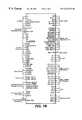
- FIG. 1Ais a block diagram of a typical microcontroller implemented according to the present invention.
- FIG. 1Bis a schematic pinout diagram of the pinouts for the microcontroller of FIG. 1A;
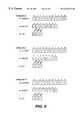
- FIGS. 2A and 2Bare timing diagrams illustrating the use of parity bits within an asynchronous serial frame having address bits
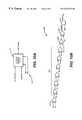
- FIG. 3is a transmit shift state machine for transmitting asynchronous serial frames
- FIG. 4is a block diagram illustrating the register contents in an asynchronous serial port according to the present invention.
- FIG. 5a diagram illustrating parity generation logic
- FIG. 6is a receive state machine for receiving asynchronous serial frames
- FIG. 7is a diagram illustrating logic for receive mode operation
- FIGS. 8A and 8Billustrate the decode logic for the receive mode according to the present invention
- FIG. 9shows exemplary signals from the decode logic of FIGS. 8A and 8B.
- FIG. 10A and 10Bare logic diagrams for generating interrupts from a parity bit.
- FIG. 1Ashown is a block diagram of a typical microcontroller M implemented according to the invention.
- a microcontrolleris preferably implemented on a single monolithic integrated circuit.
- the microcontroller Mpreferably includes an internal bus 100 coupling, an execution unit 124 , system peripherals 174 , memory peripherals 176 , and serial communication peripherals 172 .
- the execution unit 124 in the disclosed embodimentis compatible with the AM186 instruction set implemented in a variety of microcontrollers from Advanced Micro Devices, Inc., of Sunnyvale, Calif. A variety of other execution units could be used instead of the execution unit 124 .
- the system peripherals 174include a watch dog timer (WDT) 104 for generating non-maskable interrupts (NMIs), microcontroller resets, and system resets.
- An interrupt controller 108for supporting thirty-six maskable interrupt sources through the use of fifteen channels is also provided as a system peripheral.
- One disclosed system peripheralis a three-channel timer control unit 112 .
- the timer control unit 112includes three 16-bit programmable timers.
- Another system peripheralis a general-purpose direct memory access (DMA) unit 116 with four channels 0-3.
- DMAdirect memory access
- a programmable I/O unit 132 of the microcontroller Msupports user programmable input/output signal (PIOs). In the disclosed embodiment, forty-eight PIOs are provided.
- the memory peripherals 176 of the disclosed microcontrollerinclude a DRAM controller 170 , a glueless interface 168 to a RAM or ROM, and a chip select unit 126 .
- the DRAM controller 170is fully integrated into the microcontroller M.
- the chip select unit 126provides six chip select outputs for use with memory devices and eight chip select outputs for use with peripherals.
- a low speed serial port implemented as a universal asynchronous receiver/transmitter (UART) 136is provided as a serial communication peripheral.
- the low speed UART 136is typically compatible with a standard 16550 UART known to the industry.
- Another serial communication peripheral in the disclosed embodimentis a synchronous serial interface (SSI) 140 .
- SSIsynchronous serial interface
- the microcontroller Macts as a master in the synchronous serial interface 140 , which is a standard synchronous serial channel.
- the microcontroller M in the disclosed embodimentis particularly well suited to communications environments.
- the serial communication peripherals 172 of the microcontroller Minclude a number of high speed communication controllers, including a High-level Data Link Control (HDLC) controller 144 , a Universal Serial Bus (USB) controller 146 , and a high speed serial port (HSUART) 148 .
- the disclosed HDLC controller 144provides four HDLC channels 164 .
- the HDLC channels 164 and the USB controller 146can be written to and read from by a “SmartDMA” unit 150 , a unit which provides for chained buffers that are accessed via pairs of DMA channels.
- the SmartDMA unit 150allows for a high degree of packetized transfer without excessive execution unit 124 intervention.
- the SmartDMA unit 150preferably consists of four SmartDMA controllers, SmartDMA0-3, that each consists of a pair of DMA channels.
- the HSUART 148serves to form an asynchronous serial link across a bus to devices external to the microcontroller M.
- the asynchronous natureindicates that the HSUART 148 does not provide a separate clock signal to clock the data. Instead the rate at which data is sent and received must be predetermined or determined through autobauding and independently controlled on sending and receiving ends. This data rate is known as the baud rate. It should be understood that the microcontroller M may include multiple HSUARTs 148 .
- the disclosed HDLC controller 144also includes an interface multiplexer 162 .
- This multiplexer 162couples the four HDLC channels 164 , four time slot assignors (TSA) 166 , and a number of external buses.
- TSAtime slot assignors
- the HDLC channels 164can be selectively coupled to a pulse code modulation (PCM) highway, a general circuit interface (GCI), an ISDN oriented modular interface revision 2 (IOM- 2 ) serial bus, a data carrier equipment (DCE) serial interface, and other general and specific interfaces that often use packetized communication.
- PCMpulse code modulation
- GCIgeneral circuit interface
- IOM- 2ISDN oriented modular interface revision 2
- DCEdata carrier equipment
- the HDLC channels 164support HDLC, SDLC, Link Access Procedures Balanced (LAPB), Link Access Procedures on the D-channel (LAPD), and PPP, and as noted above, each include an independent time slot assignor 166 for assigning a portion of a serial frame to each HDLC for isochronous or isochronous-type communication.
- LAPBLink Access Procedures Balanced
- LAPDLink Access Procedures on the D-channel
- PPPPPP
- FIG. 1Bshown are illustrative pinouts for the microcontroller M implemented according to the invention. Illustrated are clock pinouts for the clock 102 , address and address/data bus pinouts to the bus interface unit 120 , bus status and control pinouts, again generally for the bus interface unit 120 , timer control pinouts coupled to the timer control unit 112 , USB control and transceiver control pinouts for the USB controller 146 , synchronous serial controller pinouts for the synchronous serial interface 140 , programmable I/O pinouts for the programmable I/O unit 132 , reset control pinouts, memory and peripheral control pinouts coupled to both the chip select unit 126 and the bus interface unit 120 , DMA control pinouts for the general purpose DMA unit 116 and the SmartDMA unit 150 , HDLC channel/DCE interface/PCM interface pinouts for coupling to the HDLC controller 144 , UART pinouts for the low speed UART 136 , and high speed UART pin
- pinoutsare illustrative, and a wide variety of other functional units and associated pinouts could be used without detracting from the spirit of the invention.
- a number of both the communications and general-purpose peripherals from FIG. 1Acould be eliminated, or added to, without detracting from the spirit of the invention.
- microcontrolleritself has differing definitions in industry. Some companies refer to a processor core with additional features (such as I/O) as a “microprocessor” if it has no onboard memory, and digital signal processors (DSPs) are now used for both special and general-purpose controller functions. As here used, the term “microcontroller” covers all of the products, and generally means an execution unit with added functionality all implemented on a single monolithic integrated circuit.
- asynchronous serial transmission frames 312 and 332illustrating the placement of a parity bit and an address bit according to the present invention.
- an asynchronous serial portsuch as the UART 136 or HSUART 148 , transmits seven data bits (bit 0 through bit 6 ) 302 and an optional eighth bit (bit 7 ) 304 .
- Theseare standard data bits sent in an asynchronous protocol, low order bit first.
- the address bit protocol supported by the ASPprovides an address bit 306 .
- a parity bit 308is then followed by a stop bit 310 .
- FIG. 2Billustrated is a transmission frame 332 where a parity bit 326 is placed before an address bit 328 .
- the ASPtransmits data bits zero through six 322 and a last bit 324 .
- a parity bit 326is then followed by an address bit 328 and then a stop bit 330 . Therefore by enabling early parity, the parity bit 326 is placed immediately following the last data bit 324 . Further, early parity generation is independent of the number of data bits in the frame. In other words, regardless of whether seven or eight data bits are transmitted, the parity bit 326 , with the early parity enabled, follows the last data bit transmitted.
- the address bit 306 and 328may be used in applications such as multi-drop applications that require one master device to control multiple slave devices. Although termed an address bit, bit 306 and 328 may serve as an extended bit that effectively causes interrupts within slave devices for flow and other control.
- the operation of a transmit shift state machine TX_SHIFT_SM 400is illustrated in FIG. 3 when the ASP is operated in a transmit mode.
- the TX_SHIFT_SM state machine 400is the transmit shift state machine which sets the sequence of bits for transmission frames 312 and 322 .
- the state machine 400is typically implemented in the circuitry of an ASP, such as the UART 136 or the HSUART 148 . As explained below, the TX_SHIFT_SM state machine 400 allows frame transmission to skip a data bit, thereby reducing the total number of data bits transferred.
- statereferrings to the current state of the TX_SHIFT_SM state machine 400 ; an “!” before a signal indicating logical negation, such that the expression is active when the signal is low; an “&” representing an AND logical expression; and an “+” represents an OR logical expression.
- the TX_SHIFT_SM state machine 400is clocked by a transmit clock txclk (FIG. 5 ).
- Controlbegins at a stts_idle state 404 . This state indicates that there is no data currently in a shift register 625 (FIG. 5)
- stts_start state 406On the first transmission of the transmit clock txclk after data is written to a the shift register 628 (FIG. 5 ), control proceeds to stts_start state 406 .
- the stts_start state 406indicates transmission of a start bit.
- controlproceeds from stts_bit 0 state through stts_bit 4 state 408 . This traversal of states is designated by reference numeral 408 .
- the corresponding bitis transmitted. For example, at stts_bit 0 state, the zero bit is transmitted. In a like manner, a corresponding bit is transmitted in the stts_bit 1 , stts_bit 2 , stts_bit 3 , and stts_bit 4 states.
- controlproceeds to stts_bit 5 state 410 .
- the fifth bitis transmitted.
- controlproceeds to a stts_bit 6 state 412 if a D 7 signal 504 (FIG. 5) is deasserted.
- controlproceeds to a stts_lastbit state 414 .
- controlproceeds directly to the stts_lastbit state 414 if D 7 signal 504 (FIG. 5) is asserted.
- D 7 signal 504FOG. 5
- the TX_SHIFT_SM state machine 400is able to transmit one fewer bit.
- controlproceeds to an stts_per state 418 if both parity enable signal PEN 508 (FIG. 5) and an early parity signal EARLY 514 (FIG. 5) are asserted.
- the PEN signal 508represents the state of the parity bit 308 or 326 .
- the parity bit 308 or 326is enabled if the PEN signal 508 is asserted and the parity bit 308 or 326 is disabled if the PEN signal 508 is deasserted.
- the EARLY signal 514when the PEN signal 508 is asserted, represents the location of the parity bit 308 or 326 within the transmission frame.
- the parity bit 326is placed immediately following the last data bit, shown in FIG. 2B, when the EARLY signal 514 is asserted.
- the parity bit 308is placed after the address bit 306 , shown in FIG. 2A, when the EARLY signal 514 is deasserted. However, when the PEN signal 508 is deasserted, the value of the EARLY signal 514 will have no effect on the placement of the parity bit 308 or 326 .
- controlproceeds to stts_addr state 416 when an address bit enable signal ABEN 506 is asserted along with the EARLY signal 514 .
- This transition logicsimplifies when parity is transmitted immediately after a last data bit as the EARLY signal 514 will have been previously asserted. In this case, control proceeds to stts_addr state 416 when the ABEN signal 506 is asserted.
- the ABEN signal 506represents the state of the address bit 306 or 328 .
- the address bit 328is enabled if the ABEN signal 506 is asserted and the address bit 306 or 328 is disabled if the ABEN signal 506 is deasserted. Control then proceeds to a stts_stop state 420 when either the PEN signal 508 is deasserted or when the EARLY signal 514 is asserted. Along the path just described, the EARLY signal 514 is asserted to cause the parity bit 326 to be placed immediately after the last data bit 328 . As such, control proceeds to stts_stop state 420 upon the next transmission of the transmit clock. Therefore, following the state machine path as just described, the transmitted frame will be in the form of the transmission frame 332 shown in FIG. 2B with the parity bit 326 located before the address bit 328 .
- an address bit 306can be transmitted in a location before the parity bit 308 as shown in FIG. 2 A. With the address bit 306 selected as the next bit, control proceeds from stts_last bit state 414 to stts_addr state 416 when the ABEN signal 506 is asserted and either the PEN signal 508 is deasserted or the EARLY signal 514 is deasserted. This transition logic allows the address bit to proceed a parity bit in transmission frames having both address bits and parity bits enabled. In such a transmission frame, the PEN signal 508 is asserted but the EARLY signal 514 is deasserted.
- the EARLY signal 514is deasserted and control proceeds to stts_stop state 420 on the next transmit clock transition. Therefore, along this path through the state machine 400 a transmission frame 312 has an address bit 306 placed before the parity bit 308 as shown in FIG. 2 A.
- the transmission framemay altogether exclude an address bit or a parity bit or both. Where an address bit is generated but not a parity bit, control will follow from stts_last bit state 414 to stts_addr state 416 and then to stts_stop state 420 , as the PEN signal 508 is deasserted. Likewise, in transmission frames having a parity bit but not an address bit, control will follow the path from stts_last bit state 414 to stts_per state 418 and then to stts_stop state 420 , as the ABEN signal 506 is deasserted.
- controlproceeds directly from stts_last bit state 414 to stts_stop state 420 .
- the parity bit 326(FIG. 2B) is transmitted immediately following transmission of the last data bit. This setup ensures the parity bit 326 always proceeds the address bit 328 . In this way, parity is automatically detected based on the location of the preceding data bits 322 and 324 . Since the address bit 328 follows the parity bit 326 , parity generation need not involve locating the address bit 328 .
- the placement of the parity bit 326is not dependent on a specific frame protocol. Instead, the parity bit 326 is placed at a location immediately following the last data bit (e.g. seven bit or eight bit) regardless of the frame length.
- FIG. 4illustrated is a HPSPCON0 register 500 that implements parity generation, according to the present invention, when implemented in the HSUART 148 (FIG. 1 ).
- the register 500is a 16-bit register.
- the HPSPCON0 500 registerprovides configuration settings to determine whether parity will be used (indicated by the parity enable bit PEN 508 ) and if so whether parity will precede an address bit (indicated by the early parity bit EARLY 514 ), whether an address bit 308 will be employed (indicated by the address bit enable bit ABEN 506 ), whether seven or eight bit data will be used (indicated by an enable bit D 7 504 ), and whether a second stop bit will be used (indicated by a second stop bit enable bit STP 2 502 ).
- a second stop bitis enabled if the STP 2 signal 502 is asserted, and the second stop bit is disabled if the STP 2 signal 502 is deasserted.
- paritymay be configured as either odd or even parity by an even parity bit EVN 512 . Even parity is enabled if the EVN signal 512 is asserted, and odd parity is enabled if the EVN signal 512 is deasserted.
- the bits 502 - 508 of the HPSCON0 register 500affect the length of a transmit frame.
- hardware implementations of address bitsrequired the address bit to be the “ninth” data bit regardless of whether the eighth data bit was needed and regardless of whether parity was involved.
- parity generation and detectionrequired dedicated software to first determine whether an address bit was present and, if so, to instruct the parity sequence to ignore or skip the address bit.
- the utility of such softwarehas been dependent on the number of data bits employed in the frame protocol. For example, software parity support has been developed for asynchronous serial communication frames having address bits and only seven bits of data. In accordance with the present invention, parity generation and detection may be performed without software and with frames containing any number of data bits (e.g. seven or eight bits).
- the transmit shift logic 620provides the conversion of parallel data bits DATA[ 8 : 0 ] to a serial data transmission frame 312 .
- the serial output, including the parity bit 306is presented in the txs_out signal.
- Each bit of the txs_out signalis clocked out of a latch 622 on transitions of the transmit clock signal txclk.
- the input to the latch 622is provided from the inverted output of an OR gate 624 .
- the OR gate 624passes either the value of the parity bit 306 , provided from the output of an AND gate 630 , or the values of the data bits, provided from the output of an AND gate 626 .
- the AND gate 626outputs data bits shifted from a shift register 628 into the next_bit signal when the tsx_shift signal is asserted.
- the shift register 628is a 10-bit shift register.
- the tsx_shift signalis asserted when the txs_out line should reflect the value shifted out of the shift register 628 .
- the shift register 628shifts the contents provided by the parallel data signal DATA[ 7 : 0 ] on transitions of the transmit clock txclk.
- the current value of parityis provided to the AND gate 630 .
- this current value of parityis passed.
- the txs_parity signalis asserted when the txs_out line should reflect the value of parity generation logic 642 .
- the parity bit 306will immediately follow the last data bit.
- the value of parityis output from a 2-to-1 multiplexer 632 having the next_bit signal as its select signal.
- the inputs to the multiplexer 632are provided by the non-inverted output and the inverted output of a D type flip-flop 634 , clocked by the transmit clock txclk.
- the initial parity valueis loaded in the flip-flop 634 through an AND gate 638 when a tx_write signal is asserted, indicating that there has been a write of new data to the shift register 628 . Since parity may be configured to either even or odd parity, this initial parity value depends on the even parity status bit EVN 512 .
- the next bit signaltoggles the parity value loaded in the flip-flop 634 .
- the current value of parityis then fed back to the flip-flop 634 through an AND gate 640 . Subsequent shifts of the shift register 628 cause the value stored in the flip-flop 634 to toggle depending on the value of the shifted bit in the next_bit signal.
- the end value of the parity bit for a particular transmission frameis presented on the txs_out signal through the AND gate 630 when the txs_parity signal is asserted following the shift of the last data bit.
- These figuresillustrate operation of the ASP when functioning in a receiver mode.
- Controlpasses from a str_disabled state 702 when a receive mode of the ASP 136 or 148 is entered.
- the state machine 700begins at state str_sbd 704 by detecting a start bit on a receive signal CI_RXD_HU. Once a start bit detection logic 752 finds a start bit, the n_start signal is asserted and control proceeds to a str_start state 706 .
- start bit detection logic 752checks the receiver line again near the mid-point of the bit time to determine whether a valid start bit has occurred. If no start bit is detected, control returns to state str_sbd 704 where the process repeats itself. Alternatively, where a start bit is found, control proceeds to a str_rxing state 708 , where the state machine 700 begins receiving data bits. In this state, the state machine 700 uses normal bit receive logic 756 to sample the receive signal. A receive enable signal rxs_en is asserted when a bit has been detected and is ready to shift into a shift register 758 . An internal counter 760 keeps track of the number of bits received. Control remains in the str_rxing state 708 until reception is complete.
- Reception of the frameis complete when the number of received bits matches the number of expected bits as specified by the ASP. This number is determined based on the state of the D 7 signal 504 , the PEN signal 508 , and the other status signals. Therefore, with the D 7 bit 504 , the ABEN bit 506 , and the PEN bit 508 , control will remain in the str_rxing state 708 until bits zero through seven, the parity bit, the address bit, and a stop bit have been received. In this case, control returns back to the str_sbd state 704 when a stop bit is the last bit received, detected by a stop bit detect logic 754 . Alternatively, where the last bit received is not a stop bit, control proceeds to a str_brk state 710 where a break condition is detected. Control then returns back to the str_brd state 704 along with the appropriate framing error signal.
- FIG. 8Aillustrates a bit align multiplexer which may be used by system in accordance with the present invention.
- the multiplexerreceives data from the receive shift register 758 .
- the receive datais eleven bits wide.
- the rxs_data [ 10 : 0 ]may consist of eight data bits, a parity, an address bit, and a frame bit. However, to allow maximum flexibility, these bits need not all be included in the rxs_data [ 10 : 0 ].
- a decode mechanismis required to parse the various bits of rxs_data [ 10 : 0 ] and place these bits in an acceptable format.
- a receive modeparses the receive data into a status line rxst_stat and a data line rxst_data [ 7 : 0 ].
- This parsing functionis controlled by the control signals, early parity EARLY 514 , seven data bit enable D 7 504 , parity enable PEN 508 , and address bit enable ABEN 506 . Therefore, based on these control signals, the eleven bit data received from the receive shift register 758 is parsed into a convenient format, for example separation of status and data bits.
- the output for the bit-align multiplexeris shown in detail in FIG. 8 B.
- the multiplexer outputrepresents alignment decoding of the received bits on the input line rxs_data [ 10 : 0 ] to the corresponding bit location on the output signals rxst_stat and rxst_data [ 7 : 0 ]. Because the receive shift register 758 is configured to hold a maximum number of bits, the bit-align multiplexer must fill unused spaces, where they exist, with a zero value For example, looking at the first entry or row, configuration one indicates that neither the parity bit or the address bit are enabled (the values of PEN and ABEN are both zero) and the received frame consists of eight data bits (indicated by the zero value for D 7 ).
- bits in the eleven-bit shift register 758 and on the input line rxs_data [ 10 : 0 ]are unused.
- the bit values for each of the signalsis shown in more detail in FIG. 9 .
- these unused bitsare the parity bit and the address bit, as those bits were disabled. As such, a zero value is forced on the parity bit and address bit on the output line rxst_stat.
- the value of D[ 7 ] on the output rxst_data [ 7 : 0 ] lineis the value of the ninth bit on the rxs_data [ 10 : 0 ] input line from the shift register 758 .
- the remaining bits [ 6 : 0 ] on the output line rxst_data [ 7 : 0 ]are taken in order from the bit values in bits [ 8 : 2 ] on the input line rxs_data [ 10 : 0 ].
- an example input value of rxs_data [ 10 : 0 ] of 00110100100, configuration one selected by the control signals,is parsed into rxst_data [ 7 : 0 ] as 11010010 and rxt_stat as 000 (the bit order of the status line txt_stat being, frame, parity bit, and address bit).
- the output line rxst_data [ 7 : 0 ]takes the bit values from the bit locations [ 9 : 2 ] on the input line rxs_data [ 10 : 0 ].
- the output status line rxst_stattakes its frame value from the value of bit [ 10 ] on the input line rxs_data [ 10 : 0 ]. Since neither PEN or ABEN signals are asserted, the parity and address bits on the output status line rxst_stat are zero.
- the received serial datacontains both an address bit and a parity bit (indicated by a value of one for both the PEN and ABEN signals) with the parity bit following the address bit (indicated by a zero value for the EARLY signal).
- the D 7 signalhas a value of one, only seven data bits are received. Referring to FIG. 9, the bit locations for the input and output signals are shown for configuration eight. In this case, the output data line rxst_data [ 7 : 0 ] takes its bit values from the bit values [ 7 : 1 ] of the input line rxs_data [ 10 : 0 ].
- bit values for frame, the parity bit and the address bit on the output status line rxst_statare taken from the bit locations [ 10 ], [ 9 ], and [ 8 ] respectively, of the input line rxs_data [ 10 : 0 ]. Therefore, on the input line rxs-data [ 10 : 0 ] bit [ 10 ] is translated by the bit-align multiplexer to be the frame bit on the output status line rxst_stat. Similarly, bit [ 9 ] on the input line rxs_data [ 10 : 0 ] is translated by the bit-align multiplexer to be the parity bit on the output status line rxst_stat.
- bit [ 8 ] on the input rxs_data [ 10 : 0 ]is translated by the bit-align multiplexer to be the address bit on the output status line rxst_stat. Therefore, because the control signals inform the bit-aligned multiplexer which bits to expect and in which order on the input line rxs_data [ 10 : 0 ], the bit-align multiplexer is able to parse these bits into their respective output signals. For configuration eight, the combination of control signals informs the bit-align multiplexer to expect a total of seven data bits, an address bit, and a parity bit with the address bit received prior to the parity bit.
- the same order of bitsis received on the rxs_data [ 10 : 0 ] as in configuration eight, except the parity bit is received before the address bit.
- the output data line rxst_data [ 7 : 0 ]takes its value from the same bit locations on the input rxs_data [ 10 : 0 ] as in configuration eight.
- those bit valuesmust be taken from different bit locations on the input line rxs_data [ 10 : 0 ].
- the parity valueis taken from bit [ 8 ] and the value of the address bit is taken from bit [ 9 ] on the input line rxs_data [ 10 : 0 ]. Therefore, although the value of the input line rxs_data [ 10 : 0 ] is the same for configuration eight and configuration sixteen, the output status lines in those configurations are different. This is so because the definitions represented by the received bits are different in the different configurations.
- FIGS. 10A and 10Blogic is shown for generating interrupts based on the parity bit 326 .
- the parity bit 326In frames where the parity bit 326 immediately follows a last data bit 324 , the parity bit 326 , once detected, can automatically trigger interrupts, for example on a transmission error.
- FIG. 10Ashows the overall interrupt generate block 822 having inputs of the aligned data rxst_data [ 7 : 0 ], the aligned status bits including the parity bit 326 , the even parity enable signal EVN 512 and the parity enable signal PEN 508 .
- the interrupt generate block 822generates an outgoing interrupt signal automatically, without the need for software, to be sent to the appropriate device, for example the interrupt controller 108 .
- the logic of the interrupt generate block 822is shown in more detail in FIG. 8 B.
- the logicconsists, generally, of a cascade of exclusive OR bits which sequentially compares each bit in the received frame to the output of the last bit comparison.
- the cascadebegins at XOR gate 802 where it receives the first two data bits received on rxst_data[ 7 : 0 ], D 0 and D 1 .
- the output of XOR gate 802will be true when D 0 and D 1 have different values. Alternatively, the output will be false when D 0 and D 1 have the same value.
- the output of the first XOR gate 802is then fed to the next XOR gate in the sequence, which also receives the next data bit in the sequence, D 2 .
- the output of XOR gate 806is false or zero where no parity type communication errors have occurred. In such an event, the output of the XOR gate 806 and the inverted EVN signal 512 has a value of zero, creating an output of the XOR gate 808 of false or zero. However, if a parity type error has occurred on the received frame, the output of the XOR gate 806 is a value of one while the inverted value of the EVN signal 512 is zero. In this case, since the inputs have different values, the XOR gate 808 outputs a value of one.
- a systemprovides an asynchronous serial port which supports automatic parity generation and detection for communication frames employing address bits.
- the communication framesare specified by a 7- or 8-data bit protocol.
- parity generationdoes not require dedicated software.
- the foregoing systemalso provides parity generation and detection protocol which is not dependent on data frame length.
- an asynchronous serial portaccording to the present invention provides automatic interrupt generation directly off the parity bit.
- an asynchronous serial port in accordance with the present inventionmay include transmitter logic and receiver logic typical of an asynchronous serial port. Further, it should be understood that ways for generating and detecting a parity bit directly following a last data bit other than described herein are possible without departing from the spirit of the invention.
Landscapes
- Engineering & Computer Science (AREA)
- Theoretical Computer Science (AREA)
- Physics & Mathematics (AREA)
- General Engineering & Computer Science (AREA)
- General Physics & Mathematics (AREA)
- Quality & Reliability (AREA)
- Information Transfer Systems (AREA)
Abstract
Description
Claims (31)
Priority Applications (1)
| Application Number | Priority Date | Filing Date | Title |
|---|---|---|---|
| US09/183,945US6332173B2 (en) | 1998-10-31 | 1998-10-31 | UART automatic parity support for frames with address bits |
Applications Claiming Priority (1)
| Application Number | Priority Date | Filing Date | Title |
|---|---|---|---|
| US09/183,945US6332173B2 (en) | 1998-10-31 | 1998-10-31 | UART automatic parity support for frames with address bits |
Publications (1)
| Publication Number | Publication Date |
|---|---|
| US6332173B2true US6332173B2 (en) | 2001-12-18 |
Family
ID=22674961
Family Applications (1)
| Application Number | Title | Priority Date | Filing Date |
|---|---|---|---|
| US09/183,945Expired - LifetimeUS6332173B2 (en) | 1998-10-31 | 1998-10-31 | UART automatic parity support for frames with address bits |
Country Status (1)
| Country | Link |
|---|---|
| US (1) | US6332173B2 (en) |
Cited By (11)
| Publication number | Priority date | Publication date | Assignee | Title |
|---|---|---|---|---|
| US20010034861A1 (en)* | 2000-04-25 | 2001-10-25 | Hyundai Electronics Industries Co., Ltd. | Apparatus for processing output data of base station modem for use in IS-2000 mobile communication system |
| US20030009611A1 (en)* | 2001-06-07 | 2003-01-09 | David Kutz | PC16550D UART line status register data ready bit filter and latch |
| US6675243B1 (en)* | 1999-03-17 | 2004-01-06 | Adaptec, Inc. | Methods and apparatus for implementing a device side advanced serial protocol |
| US6745254B2 (en)* | 1999-03-30 | 2004-06-01 | Siemens Energy & Automation, Inc. | Programmable logic controller method, system and apparatus |
| US7017056B1 (en) | 2000-07-31 | 2006-03-21 | Hewlett-Packard Development Company, L.P. | Method and apparatus for secure remote control of power-on state for computers |
| US20060104396A1 (en)* | 2004-10-21 | 2006-05-18 | Hewlett-Packard Development Company, L.P. | Serial bus system |
| US20110142074A1 (en)* | 2009-12-16 | 2011-06-16 | William Henry Lueckenbach | Serial communication module with multiple receiver/transmitters |
| US20150363267A1 (en)* | 2014-06-17 | 2015-12-17 | Arm Limited | Error detection in stored data values |
| US9529671B2 (en) | 2014-06-17 | 2016-12-27 | Arm Limited | Error detection in stored data values |
| US9891976B2 (en) | 2015-02-26 | 2018-02-13 | Arm Limited | Error detection circuitry for use with memory |
| CN111352888A (en)* | 2020-02-28 | 2020-06-30 | 北京铁科英迈技术有限公司 | Interrupt signal generating method and device for asynchronous transceiver |
Citations (44)
| Publication number | Priority date | Publication date | Assignee | Title |
|---|---|---|---|---|
| US3618037A (en)* | 1969-09-19 | 1971-11-02 | Burroughs Corp | Digital data communication multiple line control |
| US3940563A (en)* | 1974-10-23 | 1976-02-24 | Trw Inc. | Reframing method for a carrier system having a serial digital data bit stream |
| US4453228A (en)* | 1982-03-30 | 1984-06-05 | Burroughs Corporation | Component selection system for a multiple line adapter organization |
| EP0120172A1 (en)* | 1983-03-29 | 1984-10-03 | International Business Machines Corporation | Bus interface device for a data processing system |
| USRE31814E (en)* | 1979-07-02 | 1985-01-22 | Motorola, Inc. | Three-party conference circuit for digital time-division-multiplex communication systems |
| DE3610523A1 (en)* | 1986-03-27 | 1987-10-01 | Siemens Ag | Method for asynchronous serial data transmission and arrangement to carry out the method |
| EP0257405A1 (en)* | 1986-08-07 | 1988-03-02 | Siemens Aktiengesellschaft | Method and apparatus for updating control bit combinations |
| EP0311448A2 (en)* | 1987-10-09 | 1989-04-12 | Kabushiki Kaisha Toshiba | Digital multiplexer |
| US4862480A (en)* | 1987-04-09 | 1989-08-29 | Integrated Network Corporation | Digital data service system |
| EP0339305A2 (en)* | 1988-04-25 | 1989-11-02 | International Business Machines Corporation | Parity prediction for binary adders with selection |
| US4907225A (en)* | 1987-04-03 | 1990-03-06 | Advanced Micro Devices, Inc. | Data protocol controller |
| US4949333A (en)* | 1987-04-02 | 1990-08-14 | Advanced Micro Devices, Inc. | Enhanced universal asynchronous receiver-transmitter |
| US5043943A (en)* | 1990-06-18 | 1991-08-27 | Motorola, Inc. | Cache memory with a parity write control circuit |
| US5117428A (en)* | 1989-11-22 | 1992-05-26 | Unisys Corporation | System for memory data integrity |
| US5123091A (en)* | 1987-08-13 | 1992-06-16 | Digital Equipment Corporation | Data processing system and method for packetizing data from peripherals |
| US5140679A (en)* | 1988-09-14 | 1992-08-18 | National Semiconductor Corporation | Universal asynchronous receiver/transmitter |
| US5173683A (en) | 1991-04-22 | 1992-12-22 | Simplex Time Recorder Co. | Apparatus and method for multiplexing multiple data and analog values in a peripheral device |
| US5187708A (en)* | 1989-10-06 | 1993-02-16 | Matsushita Electric Industrial Co., Ltd. | Communication device for layered protocols |
| US5192947A (en) | 1990-02-02 | 1993-03-09 | Simon Neustein | Credit card pager apparatus |
| US5263054A (en) | 1992-05-21 | 1993-11-16 | International Business Machines Corporation | Method and system for interpolating baud rate timing recovery for asynchronous start stop protocol |
| US5345582A (en)* | 1991-12-20 | 1994-09-06 | Unisys Corporation | Failure detection for instruction processor associative cache memories |
| US5357249A (en)* | 1991-10-21 | 1994-10-18 | Trw Inc. | Apparatus and method for high speed flexible multiplexing for fiber optic data transmissions |
| JPH0723013A (en)* | 1993-06-30 | 1995-01-24 | Nec Corp | Frame transmission system |
| US5530704A (en) | 1995-02-16 | 1996-06-25 | Motorola, Inc. | Method and apparatus for synchronizing radio ports in a commnuication system |
| US5537425A (en)* | 1992-09-29 | 1996-07-16 | International Business Machines Corporation | Parity-based error detection in a memory controller |
| US5555438A (en)* | 1991-07-24 | 1996-09-10 | Allen-Bradley Company, Inc. | Method for synchronously transferring serial data to and from an input/output (I/O) module with true and complement error detection coding |
| US5682552A (en)* | 1989-06-30 | 1997-10-28 | Hitachi, Ltd. | Data communication adapter and data communication terminal apparatus for performing data transmission and reception between terminals |
| US5713028A (en)* | 1995-01-30 | 1998-01-27 | Fujitsu Limited | Micro-processor unit having universal asynchronous receiver/transmitter |
| US5717870A (en)* | 1994-10-26 | 1998-02-10 | Hayes Microcomputer Products, Inc. | Serial port controller for preventing repetitive interrupt signals |
| US5729004A (en)* | 1994-09-30 | 1998-03-17 | Samsung Electronics Co., Ltd. | Data communication device and method of a smart card |
| US5748887A (en)* | 1995-04-18 | 1998-05-05 | Hyundai Electronics Industries Co., Ltd. | Inter-processor asynchronous serial communication transmission/reception apparatus using each other's memories |
| US5805909A (en)* | 1995-08-03 | 1998-09-08 | Texas Instruments Incorporated | Microprocessors or microcontroller utilizing FLL clock having a reduced power state |
| US5808909A (en) | 1995-09-15 | 1998-09-15 | Rees; James G. | Electronic brake control valve tester for rail cars and trains |
| US5878061A (en)* | 1996-03-14 | 1999-03-02 | Intel Corporation | Providing serial data clock signal transitions with parity bits |
| US5896549A (en) | 1997-02-04 | 1999-04-20 | Advanced Micro Devices, Inc. | System for selecting between internal and external DMA request where ASP generates internal request is determined by at least one bit position within configuration register |
| US5938773A (en)* | 1996-03-14 | 1999-08-17 | Intel Corporation | Sideband signaling with parity bit schemes |
| US5958024A (en)* | 1997-08-29 | 1999-09-28 | Advanced Micro Devices, Inc. | System having a receive data register for storing at least nine data bits of frame and status bits indicating the status of asynchronous serial receiver |
| EP0830679B1 (en)* | 1995-06-07 | 1999-10-20 | Seagate Technology, Inc. | RATE n/(n+1) CODE FOR EMBEDDED SERVO ADDRESS ENCODING |
| US5978865A (en)* | 1997-02-04 | 1999-11-02 | Advanced Micro Devices, Inc. | System for performing DMA transfers where an interrupt request signal is generated based on the value of the last of a plurality of data bits transmitted |
| US5978954A (en)* | 1997-11-25 | 1999-11-02 | Palmchip Corporation | On-the-fly error detection and correction buffer processor |
| US5983291A (en)* | 1996-09-24 | 1999-11-09 | Cirrus Logic, Inc. | System for storing each of streams of data bits corresponding from a separator thereby allowing an input port accommodating plurality of data frame sub-functions concurrently |
| US6015081A (en) | 1991-02-25 | 2000-01-18 | Canon Kabushiki Kaisha | Electrical connections using deforming compression |
| US6028675A (en) | 1997-05-09 | 2000-02-22 | Lexmark International, Inc. | Transmission error detection system and method for imaging systems including printers with intelligent options |
| US6105081A (en)* | 1998-06-01 | 2000-08-15 | Advanced Micro Devices, Inc. | UART character matching used for address matching on a register-by-register basis |
- 1998
- 1998-10-31USUS09/183,945patent/US6332173B2/ennot_activeExpired - Lifetime
Patent Citations (44)
| Publication number | Priority date | Publication date | Assignee | Title |
|---|---|---|---|---|
| US3618037A (en)* | 1969-09-19 | 1971-11-02 | Burroughs Corp | Digital data communication multiple line control |
| US3940563A (en)* | 1974-10-23 | 1976-02-24 | Trw Inc. | Reframing method for a carrier system having a serial digital data bit stream |
| USRE31814E (en)* | 1979-07-02 | 1985-01-22 | Motorola, Inc. | Three-party conference circuit for digital time-division-multiplex communication systems |
| US4453228A (en)* | 1982-03-30 | 1984-06-05 | Burroughs Corporation | Component selection system for a multiple line adapter organization |
| EP0120172A1 (en)* | 1983-03-29 | 1984-10-03 | International Business Machines Corporation | Bus interface device for a data processing system |
| DE3610523A1 (en)* | 1986-03-27 | 1987-10-01 | Siemens Ag | Method for asynchronous serial data transmission and arrangement to carry out the method |
| EP0257405A1 (en)* | 1986-08-07 | 1988-03-02 | Siemens Aktiengesellschaft | Method and apparatus for updating control bit combinations |
| US4949333A (en)* | 1987-04-02 | 1990-08-14 | Advanced Micro Devices, Inc. | Enhanced universal asynchronous receiver-transmitter |
| US4907225A (en)* | 1987-04-03 | 1990-03-06 | Advanced Micro Devices, Inc. | Data protocol controller |
| US4862480A (en)* | 1987-04-09 | 1989-08-29 | Integrated Network Corporation | Digital data service system |
| US5123091A (en)* | 1987-08-13 | 1992-06-16 | Digital Equipment Corporation | Data processing system and method for packetizing data from peripherals |
| EP0311448A2 (en)* | 1987-10-09 | 1989-04-12 | Kabushiki Kaisha Toshiba | Digital multiplexer |
| EP0339305A2 (en)* | 1988-04-25 | 1989-11-02 | International Business Machines Corporation | Parity prediction for binary adders with selection |
| US5140679A (en)* | 1988-09-14 | 1992-08-18 | National Semiconductor Corporation | Universal asynchronous receiver/transmitter |
| US5682552A (en)* | 1989-06-30 | 1997-10-28 | Hitachi, Ltd. | Data communication adapter and data communication terminal apparatus for performing data transmission and reception between terminals |
| US5187708A (en)* | 1989-10-06 | 1993-02-16 | Matsushita Electric Industrial Co., Ltd. | Communication device for layered protocols |
| US5117428A (en)* | 1989-11-22 | 1992-05-26 | Unisys Corporation | System for memory data integrity |
| US5192947A (en) | 1990-02-02 | 1993-03-09 | Simon Neustein | Credit card pager apparatus |
| US5043943A (en)* | 1990-06-18 | 1991-08-27 | Motorola, Inc. | Cache memory with a parity write control circuit |
| US6015081A (en) | 1991-02-25 | 2000-01-18 | Canon Kabushiki Kaisha | Electrical connections using deforming compression |
| US5173683A (en) | 1991-04-22 | 1992-12-22 | Simplex Time Recorder Co. | Apparatus and method for multiplexing multiple data and analog values in a peripheral device |
| US5555438A (en)* | 1991-07-24 | 1996-09-10 | Allen-Bradley Company, Inc. | Method for synchronously transferring serial data to and from an input/output (I/O) module with true and complement error detection coding |
| US5357249A (en)* | 1991-10-21 | 1994-10-18 | Trw Inc. | Apparatus and method for high speed flexible multiplexing for fiber optic data transmissions |
| US5345582A (en)* | 1991-12-20 | 1994-09-06 | Unisys Corporation | Failure detection for instruction processor associative cache memories |
| US5263054A (en) | 1992-05-21 | 1993-11-16 | International Business Machines Corporation | Method and system for interpolating baud rate timing recovery for asynchronous start stop protocol |
| US5537425A (en)* | 1992-09-29 | 1996-07-16 | International Business Machines Corporation | Parity-based error detection in a memory controller |
| JPH0723013A (en)* | 1993-06-30 | 1995-01-24 | Nec Corp | Frame transmission system |
| US5729004A (en)* | 1994-09-30 | 1998-03-17 | Samsung Electronics Co., Ltd. | Data communication device and method of a smart card |
| US5717870A (en)* | 1994-10-26 | 1998-02-10 | Hayes Microcomputer Products, Inc. | Serial port controller for preventing repetitive interrupt signals |
| US5713028A (en)* | 1995-01-30 | 1998-01-27 | Fujitsu Limited | Micro-processor unit having universal asynchronous receiver/transmitter |
| US5530704A (en) | 1995-02-16 | 1996-06-25 | Motorola, Inc. | Method and apparatus for synchronizing radio ports in a commnuication system |
| US5748887A (en)* | 1995-04-18 | 1998-05-05 | Hyundai Electronics Industries Co., Ltd. | Inter-processor asynchronous serial communication transmission/reception apparatus using each other's memories |
| EP0830679B1 (en)* | 1995-06-07 | 1999-10-20 | Seagate Technology, Inc. | RATE n/(n+1) CODE FOR EMBEDDED SERVO ADDRESS ENCODING |
| US5805909A (en)* | 1995-08-03 | 1998-09-08 | Texas Instruments Incorporated | Microprocessors or microcontroller utilizing FLL clock having a reduced power state |
| US5808909A (en) | 1995-09-15 | 1998-09-15 | Rees; James G. | Electronic brake control valve tester for rail cars and trains |
| US5938773A (en)* | 1996-03-14 | 1999-08-17 | Intel Corporation | Sideband signaling with parity bit schemes |
| US5878061A (en)* | 1996-03-14 | 1999-03-02 | Intel Corporation | Providing serial data clock signal transitions with parity bits |
| US5983291A (en)* | 1996-09-24 | 1999-11-09 | Cirrus Logic, Inc. | System for storing each of streams of data bits corresponding from a separator thereby allowing an input port accommodating plurality of data frame sub-functions concurrently |
| US5896549A (en) | 1997-02-04 | 1999-04-20 | Advanced Micro Devices, Inc. | System for selecting between internal and external DMA request where ASP generates internal request is determined by at least one bit position within configuration register |
| US5978865A (en)* | 1997-02-04 | 1999-11-02 | Advanced Micro Devices, Inc. | System for performing DMA transfers where an interrupt request signal is generated based on the value of the last of a plurality of data bits transmitted |
| US6028675A (en) | 1997-05-09 | 2000-02-22 | Lexmark International, Inc. | Transmission error detection system and method for imaging systems including printers with intelligent options |
| US5958024A (en)* | 1997-08-29 | 1999-09-28 | Advanced Micro Devices, Inc. | System having a receive data register for storing at least nine data bits of frame and status bits indicating the status of asynchronous serial receiver |
| US5978954A (en)* | 1997-11-25 | 1999-11-02 | Palmchip Corporation | On-the-fly error detection and correction buffer processor |
| US6105081A (en)* | 1998-06-01 | 2000-08-15 | Advanced Micro Devices, Inc. | UART character matching used for address matching on a register-by-register basis |
Non-Patent Citations (13)
| Title |
|---|
| "8-bit Single-Chip Microcontroller", NEC MOS Integrated Circuit Jul. 1997, Doc No. U12436EJ1V0DS00 (1st ed.), pp. 7-48.* |
| "Am186(TM) Ed/EDLV Microcontrollers User's Manual," Advanced Micro Devices, Inc. 1997, Chapters 1 and 10. |
| "Am186(TM) ES/ESLV and AM188(TM) ES/ESLV High Performance, 80C186-/80C188-Compatible and 80 L 186-/80L 188-Compatible, 16-Bit Embedded Microcontrollers," Advanced Micro Devices, Inc., Feb. 1997, pp. 1-2, 5-6, 9-10 and 51-52. |
| "Am186™ Ed/EDLV Microcontrollers User's Manual," Advanced Micro Devices, Inc. 1997, Chapters 1 and 10. |
| "Am186™ ES/ESLV and AM188™ ES/ESLV High Performance, 80C186-/80C188-Compatible and 80 L 186-/80L 188-Compatible, 16-Bit Embedded Microcontrollers," Advanced Micro Devices, Inc., Feb. 1997, pp. 1-2, 5-6, 9-10 and 51-52. |
| "Asynchronous serial multidrop systems using 9-data bit frames," Electronics Products Design, Jan. 1998, pp. C15-C18. |
| "Native I/O Ports for Personal Computer System Board", IBM Tech. Discl. Bull., Jun. 1987, V. 30, No. 1, pp. 18-25.* |
| "Serial Data Link Design for an Automotive Display System", IBM Tech. Discl. Bull., Aug. 1988, V. 31, No. 3, pp. 471-474.* |
| "Use of Dynamic Memory Access Asynchronous Communications in the Asynchronous Communications Device Interface", IBM Tech. Discl. Bull., Sep. 1992, V. 35, No. 4A, pp. 132-134.* |
| Chou et al. "Synthesis of the Hardware/Software Interface in Microcontroller-Based Systems", Proceedings of the 1992 IEEE/ACM International Conf. on Computer-Aided Design, 1992, pp. 488-495.* |
| Frank Durda IV, "The UART: What It Is and How It Works", FreeBSD Handbook, Jan. 1996, Appendix F. PC Hardware Compatibility, F.4.3.1.* |
| Vahid et al. "The Case for a Configure-and-Execute Paradigm", Proceedings of the Seventh International Workshop on Hardware/Software Codesign, 1999, pp. 59-63.* |
| Yang et al. "Optimal Frame Rate Detection for CDMA Mobile Stations with Variable-Rate Data Transmission", Communications, 1999. APCC/OECC '99, 5th Asia-Pacific Conference on, pp. 713-716.* |
Cited By (14)
| Publication number | Priority date | Publication date | Assignee | Title |
|---|---|---|---|---|
| US6675243B1 (en)* | 1999-03-17 | 2004-01-06 | Adaptec, Inc. | Methods and apparatus for implementing a device side advanced serial protocol |
| US6745254B2 (en)* | 1999-03-30 | 2004-06-01 | Siemens Energy & Automation, Inc. | Programmable logic controller method, system and apparatus |
| US20010034861A1 (en)* | 2000-04-25 | 2001-10-25 | Hyundai Electronics Industries Co., Ltd. | Apparatus for processing output data of base station modem for use in IS-2000 mobile communication system |
| US7017056B1 (en) | 2000-07-31 | 2006-03-21 | Hewlett-Packard Development Company, L.P. | Method and apparatus for secure remote control of power-on state for computers |
| US20030009611A1 (en)* | 2001-06-07 | 2003-01-09 | David Kutz | PC16550D UART line status register data ready bit filter and latch |
| US6766396B2 (en)* | 2001-06-07 | 2004-07-20 | Lucent Technologies Inc. | PC16550D UART line status register data ready bit filter and latch |
| US20060104396A1 (en)* | 2004-10-21 | 2006-05-18 | Hewlett-Packard Development Company, L.P. | Serial bus system |
| US7650450B2 (en)* | 2004-10-21 | 2010-01-19 | Hewlett Packard Development Company, L.P. | Serial bus system |
| US20110142074A1 (en)* | 2009-12-16 | 2011-06-16 | William Henry Lueckenbach | Serial communication module with multiple receiver/transmitters |
| US20150363267A1 (en)* | 2014-06-17 | 2015-12-17 | Arm Limited | Error detection in stored data values |
| US9529671B2 (en) | 2014-06-17 | 2016-12-27 | Arm Limited | Error detection in stored data values |
| US9760438B2 (en)* | 2014-06-17 | 2017-09-12 | Arm Limited | Error detection in stored data values |
| US9891976B2 (en) | 2015-02-26 | 2018-02-13 | Arm Limited | Error detection circuitry for use with memory |
| CN111352888A (en)* | 2020-02-28 | 2020-06-30 | 北京铁科英迈技术有限公司 | Interrupt signal generating method and device for asynchronous transceiver |
Similar Documents
| Publication | Publication Date | Title |
|---|---|---|
| US5561826A (en) | Configurable architecture for serial communication | |
| US4780814A (en) | Global serial channel for microcontroller | |
| US7328399B2 (en) | Synchronous serial data communication bus | |
| US5557751A (en) | Method and apparatus for serial data communications using FIFO buffers | |
| US6298396B1 (en) | System for loading a current buffer desciptor register with a value different from current value to cause a previously read buffer descriptor to be read again | |
| KR970007764B1 (en) | Program controller | |
| US5299193A (en) | Signal interface for coupling a network front end circuit to a network adapter circuit | |
| EP0105688A2 (en) | Line support processor for data transfer system | |
| US6212593B1 (en) | Method and apparatus for generating interrupts on a buffer by buffer basis in buffer descriptor ring direct memory access system | |
| US6366610B1 (en) | Autobauding with adjustment to a programmable baud rate | |
| US5958024A (en) | System having a receive data register for storing at least nine data bits of frame and status bits indicating the status of asynchronous serial receiver | |
| US4048673A (en) | Cpu - i/o bus interface for a data processing system | |
| US5159684A (en) | Data communication interface integrated circuit with data-echoing and non-echoing communication modes | |
| US6332173B2 (en) | UART automatic parity support for frames with address bits | |
| US5564061A (en) | Reconfigurable architecture for multi-protocol data communications having selection means and a plurality of register sets | |
| US5884044A (en) | Dedicated DDC integrable multimode communications cell | |
| US6170027B1 (en) | LPC/ISA bridge and its bridging method | |
| US6535522B1 (en) | Multiple protocol interface and method for use in a communications system | |
| EP1275048B1 (en) | Extended cardbus/pc card controller with split-bridge technology | |
| US6327259B1 (en) | Flexible placement of serial data within a time divisioned multiplexed frame through programmable time slot start and stop bit positions | |
| WO1996037850A1 (en) | Bidirectional parallel signal interface | |
| GB1581838A (en) | I/o bus transceiver for a data processing system | |
| JPH03164961A (en) | Apparatus and method for transmitting data via serial data bus | |
| US6105081A (en) | UART character matching used for address matching on a register-by-register basis | |
| US6587954B1 (en) | Method and interface for clock switching |
Legal Events
| Date | Code | Title | Description |
|---|---|---|---|
| AS | Assignment | Owner name:ADVANCED MICRO DEVICES, INC., TEXAS Free format text:ASSIGNMENT OF ASSIGNORS INTEREST;ASSIGNOR:TYPALDOS, MELANIE D.;REEL/FRAME:009561/0900 Effective date:19981030 | |
| STCF | Information on status: patent grant | Free format text:PATENTED CASE | |
| FEPP | Fee payment procedure | Free format text:PAT HOLDER NO LONGER CLAIMS SMALL ENTITY STATUS, ENTITY STATUS SET TO UNDISCOUNTED (ORIGINAL EVENT CODE: STOL); ENTITY STATUS OF PATENT OWNER: LARGE ENTITY | |
| REFU | Refund | Free format text:REFUND - SURCHARGE, PETITION TO ACCEPT PYMT AFTER EXP, UNINTENTIONAL (ORIGINAL EVENT CODE: R2551); ENTITY STATUS OF PATENT OWNER: LARGE ENTITY | |
| FPAY | Fee payment | Year of fee payment:4 | |
| FPAY | Fee payment | Year of fee payment:8 | |
| AS | Assignment | Owner name:GLOBALFOUNDRIES INC., CAYMAN ISLANDS Free format text:ASSIGNMENT OF ASSIGNORS INTEREST;ASSIGNOR:AMD TECHNOLOGIES HOLDINGS, INC.;REEL/FRAME:022764/0544 Effective date:20090302 Owner name:AMD TECHNOLOGIES HOLDINGS, INC., CALIFORNIA Free format text:ASSIGNMENT OF ASSIGNORS INTEREST;ASSIGNOR:ADVANCED MICRO DEVICES, INC.;REEL/FRAME:022764/0488 Effective date:20090302 | |
| FPAY | Fee payment | Year of fee payment:12 | |
| AS | Assignment | Owner name:WILMINGTON TRUST, NATIONAL ASSOCIATION, DELAWARE Free format text:SECURITY AGREEMENT;ASSIGNOR:GLOBALFOUNDRIES INC.;REEL/FRAME:049490/0001 Effective date:20181127 | |
| AS | Assignment | Owner name:GLOBALFOUNDRIES INC., CAYMAN ISLANDS Free format text:RELEASE BY SECURED PARTY;ASSIGNOR:WILMINGTON TRUST, NATIONAL ASSOCIATION;REEL/FRAME:054636/0001 Effective date:20201117 | |
| AS | Assignment | Owner name:GLOBALFOUNDRIES U.S. INC., NEW YORK Free format text:RELEASE BY SECURED PARTY;ASSIGNOR:WILMINGTON TRUST, NATIONAL ASSOCIATION;REEL/FRAME:056987/0001 Effective date:20201117 |