US6332082B1 - Personal communicator telephone system - Google Patents
Personal communicator telephone systemDownload PDFInfo
- Publication number
- US6332082B1 US6332082B1US09/415,090US41509099AUS6332082B1US 6332082 B1US6332082 B1US 6332082B1US 41509099 AUS41509099 AUS 41509099AUS 6332082 B1US6332082 B1US 6332082B1
- Authority
- US
- United States
- Prior art keywords
- subscriber
- control
- call
- passes
- telephone
- Prior art date
- Legal status (The legal status is an assumption and is not a legal conclusion. Google has not performed a legal analysis and makes no representation as to the accuracy of the status listed.)
- Expired - Lifetime
Links
Images


Classifications
- H—ELECTRICITY
- H04—ELECTRIC COMMUNICATION TECHNIQUE
- H04W—WIRELESS COMMUNICATION NETWORKS
- H04W4/00—Services specially adapted for wireless communication networks; Facilities therefor
- H04W4/16—Communication-related supplementary services, e.g. call-transfer or call-hold
- H—ELECTRICITY
- H04—ELECTRIC COMMUNICATION TECHNIQUE
- H04M—TELEPHONIC COMMUNICATION
- H04M1/00—Substation equipment, e.g. for use by subscribers
- H04M1/006—Call diverting means
- H—ELECTRICITY
- H04—ELECTRIC COMMUNICATION TECHNIQUE
- H04M—TELEPHONIC COMMUNICATION
- H04M1/00—Substation equipment, e.g. for use by subscribers
- H04M1/26—Devices for calling a subscriber
- H04M1/27—Devices whereby a plurality of signals may be stored simultaneously
- H—ELECTRICITY
- H04—ELECTRIC COMMUNICATION TECHNIQUE
- H04M—TELEPHONIC COMMUNICATION
- H04M1/00—Substation equipment, e.g. for use by subscribers
- H04M1/64—Automatic arrangements for answering calls; Automatic arrangements for recording messages for absent subscribers; Arrangements for recording conversations
- H04M1/65—Recording arrangements for recording a message from the calling party
- H04M1/652—Means for playing back the recorded messages by remote control over a telephone line
- H—ELECTRICITY
- H04—ELECTRIC COMMUNICATION TECHNIQUE
- H04M—TELEPHONIC COMMUNICATION
- H04M1/00—Substation equipment, e.g. for use by subscribers
- H04M1/64—Automatic arrangements for answering calls; Automatic arrangements for recording messages for absent subscribers; Arrangements for recording conversations
- H04M1/65—Recording arrangements for recording a message from the calling party
- H04M1/658—Means for redirecting recorded messages to other extensions or equipment
- H—ELECTRICITY
- H04—ELECTRIC COMMUNICATION TECHNIQUE
- H04M—TELEPHONIC COMMUNICATION
- H04M1/00—Substation equipment, e.g. for use by subscribers
- H04M1/66—Substation equipment, e.g. for use by subscribers with means for preventing unauthorised or fraudulent calling
- H04M1/663—Preventing unauthorised calls to a telephone set
- H04M1/665—Preventing unauthorised calls to a telephone set by checking the validity of a code
- H—ELECTRICITY
- H04—ELECTRIC COMMUNICATION TECHNIQUE
- H04M—TELEPHONIC COMMUNICATION
- H04M11/00—Telephonic communication systems specially adapted for combination with other electrical systems
- H—ELECTRICITY
- H04—ELECTRIC COMMUNICATION TECHNIQUE
- H04M—TELEPHONIC COMMUNICATION
- H04M11/00—Telephonic communication systems specially adapted for combination with other electrical systems
- H04M11/02—Telephonic communication systems specially adapted for combination with other electrical systems with bell or annunciator systems
- H04M11/022—Paging systems
- H—ELECTRICITY
- H04—ELECTRIC COMMUNICATION TECHNIQUE
- H04M—TELEPHONIC COMMUNICATION
- H04M3/00—Automatic or semi-automatic exchanges
- H04M3/38—Graded-service arrangements, i.e. some subscribers prevented from establishing certain connections
- H04M3/382—Graded-service arrangements, i.e. some subscribers prevented from establishing certain connections using authorisation codes or passwords
- H—ELECTRICITY
- H04—ELECTRIC COMMUNICATION TECHNIQUE
- H04M—TELEPHONIC COMMUNICATION
- H04M3/00—Automatic or semi-automatic exchanges
- H04M3/42—Systems providing special services or facilities to subscribers
- H—ELECTRICITY
- H04—ELECTRIC COMMUNICATION TECHNIQUE
- H04M—TELEPHONIC COMMUNICATION
- H04M3/00—Automatic or semi-automatic exchanges
- H04M3/42—Systems providing special services or facilities to subscribers
- H04M3/42229—Personal communication services, i.e. services related to one subscriber independent of his terminal and/or location
- H—ELECTRICITY
- H04—ELECTRIC COMMUNICATION TECHNIQUE
- H04M—TELEPHONIC COMMUNICATION
- H04M3/00—Automatic or semi-automatic exchanges
- H04M3/42—Systems providing special services or facilities to subscribers
- H04M3/428—Arrangements for placing incoming calls on hold
- H—ELECTRICITY
- H04—ELECTRIC COMMUNICATION TECHNIQUE
- H04M—TELEPHONIC COMMUNICATION
- H04M3/00—Automatic or semi-automatic exchanges
- H04M3/42—Systems providing special services or facilities to subscribers
- H04M3/436—Arrangements for screening incoming calls, i.e. evaluating the characteristics of a call before deciding whether to answer it
- H—ELECTRICITY
- H04—ELECTRIC COMMUNICATION TECHNIQUE
- H04M—TELEPHONIC COMMUNICATION
- H04M3/00—Automatic or semi-automatic exchanges
- H04M3/42—Systems providing special services or facilities to subscribers
- H04M3/50—Centralised arrangements for answering calls; Centralised arrangements for recording messages for absent or busy subscribers ; Centralised arrangements for recording messages
- H04M3/527—Centralised call answering arrangements not requiring operator intervention
- H—ELECTRICITY
- H04—ELECTRIC COMMUNICATION TECHNIQUE
- H04M—TELEPHONIC COMMUNICATION
- H04M3/00—Automatic or semi-automatic exchanges
- H04M3/42—Systems providing special services or facilities to subscribers
- H04M3/54—Arrangements for diverting calls for one subscriber to another predetermined subscriber
- H—ELECTRICITY
- H04—ELECTRIC COMMUNICATION TECHNIQUE
- H04Q—SELECTING
- H04Q11/00—Selecting arrangements for multiplex systems
- H04Q11/04—Selecting arrangements for multiplex systems for time-division multiplexing
- H04Q11/0428—Integrated services digital network, i.e. systems for transmission of different types of digitised signals, e.g. speech, data, telecentral, television signals
- H04Q11/0435—Details
- H04Q11/0457—Connection protocols
- H—ELECTRICITY
- H04—ELECTRIC COMMUNICATION TECHNIQUE
- H04Q—SELECTING
- H04Q3/00—Selecting arrangements
- H04Q3/0016—Arrangements providing connection between exchanges
- H04Q3/0029—Provisions for intelligent networking
- H04Q3/005—Personal communication services, e.g. provisions for portability of subscriber numbers
- H—ELECTRICITY
- H04—ELECTRIC COMMUNICATION TECHNIQUE
- H04Q—SELECTING
- H04Q3/00—Selecting arrangements
- H04Q3/42—Circuit arrangements for indirect selecting controlled by common circuits, e.g. register controller, marker
- H04Q3/54—Circuit arrangements for indirect selecting controlled by common circuits, e.g. register controller, marker in which the logic circuitry controlling the exchange is centralised
- H04Q3/542—Logic circuits or arrangements therefor
- H—ELECTRICITY
- H04—ELECTRIC COMMUNICATION TECHNIQUE
- H04Q—SELECTING
- H04Q3/00—Selecting arrangements
- H04Q3/42—Circuit arrangements for indirect selecting controlled by common circuits, e.g. register controller, marker
- H04Q3/54—Circuit arrangements for indirect selecting controlled by common circuits, e.g. register controller, marker in which the logic circuitry controlling the exchange is centralised
- H04Q3/545—Circuit arrangements for indirect selecting controlled by common circuits, e.g. register controller, marker in which the logic circuitry controlling the exchange is centralised using a stored programme
- H04Q3/54508—Configuration, initialisation
- H04Q3/54525—Features introduction
- H—ELECTRICITY
- H04—ELECTRIC COMMUNICATION TECHNIQUE
- H04Q—SELECTING
- H04Q3/00—Selecting arrangements
- H04Q3/42—Circuit arrangements for indirect selecting controlled by common circuits, e.g. register controller, marker
- H04Q3/54—Circuit arrangements for indirect selecting controlled by common circuits, e.g. register controller, marker in which the logic circuitry controlling the exchange is centralised
- H04Q3/545—Circuit arrangements for indirect selecting controlled by common circuits, e.g. register controller, marker in which the logic circuitry controlling the exchange is centralised using a stored programme
- H04Q3/54541—Circuit arrangements for indirect selecting controlled by common circuits, e.g. register controller, marker in which the logic circuitry controlling the exchange is centralised using a stored programme using multi-processor systems
- H04Q3/54566—Intelligent peripherals, adjunct processors
- H—ELECTRICITY
- H04—ELECTRIC COMMUNICATION TECHNIQUE
- H04Q—SELECTING
- H04Q3/00—Selecting arrangements
- H04Q3/42—Circuit arrangements for indirect selecting controlled by common circuits, e.g. register controller, marker
- H04Q3/54—Circuit arrangements for indirect selecting controlled by common circuits, e.g. register controller, marker in which the logic circuitry controlling the exchange is centralised
- H04Q3/545—Circuit arrangements for indirect selecting controlled by common circuits, e.g. register controller, marker in which the logic circuitry controlling the exchange is centralised using a stored programme
- H04Q3/54575—Software application
- H04Q3/54591—Supervision, e.g. fault localisation, traffic measurements, avoiding errors, failure recovery, monitoring, statistical analysis
- H—ELECTRICITY
- H04—ELECTRIC COMMUNICATION TECHNIQUE
- H04Q—SELECTING
- H04Q3/00—Selecting arrangements
- H04Q3/58—Arrangements providing connection between main exchange and sub-exchange or satellite
- H04Q3/62—Arrangements providing connection between main exchange and sub-exchange or satellite for connecting to private branch exchanges
- H04Q3/622—Circuit arrangements therefor
- H—ELECTRICITY
- H04—ELECTRIC COMMUNICATION TECHNIQUE
- H04Q—SELECTING
- H04Q3/00—Selecting arrangements
- H04Q3/58—Arrangements providing connection between main exchange and sub-exchange or satellite
- H04Q3/62—Arrangements providing connection between main exchange and sub-exchange or satellite for connecting to private branch exchanges
- H04Q3/625—Arrangements in the private branch exchange
- H04Q3/627—Details
- H—ELECTRICITY
- H04—ELECTRIC COMMUNICATION TECHNIQUE
- H04W—WIRELESS COMMUNICATION NETWORKS
- H04W76/00—Connection management
- H04W76/10—Connection setup
- H—ELECTRICITY
- H04—ELECTRIC COMMUNICATION TECHNIQUE
- H04M—TELEPHONIC COMMUNICATION
- H04M2203/00—Aspects of automatic or semi-automatic exchanges
- H04M2203/20—Aspects of automatic or semi-automatic exchanges related to features of supplementary services
- H04M2203/2005—Temporarily overriding a service configuration
- H—ELECTRICITY
- H04—ELECTRIC COMMUNICATION TECHNIQUE
- H04M—TELEPHONIC COMMUNICATION
- H04M2203/00—Aspects of automatic or semi-automatic exchanges
- H04M2203/20—Aspects of automatic or semi-automatic exchanges related to features of supplementary services
- H04M2203/2011—Service processing based on information specified by a party before or during a call, e.g. information, tone or routing selection
- H—ELECTRICITY
- H04—ELECTRIC COMMUNICATION TECHNIQUE
- H04M—TELEPHONIC COMMUNICATION
- H04M2203/00—Aspects of automatic or semi-automatic exchanges
- H04M2203/20—Aspects of automatic or semi-automatic exchanges related to features of supplementary services
- H04M2203/2072—Schedules, e.g. personal calendars
- H—ELECTRICITY
- H04—ELECTRIC COMMUNICATION TECHNIQUE
- H04M—TELEPHONIC COMMUNICATION
- H04M2242/00—Special services or facilities
- H04M2242/22—Automatic class or number identification arrangements
- H—ELECTRICITY
- H04—ELECTRIC COMMUNICATION TECHNIQUE
- H04M—TELEPHONIC COMMUNICATION
- H04M2242/00—Special services or facilities
- H04M2242/30—Determination of the location of a subscriber
- H—ELECTRICITY
- H04—ELECTRIC COMMUNICATION TECHNIQUE
- H04M—TELEPHONIC COMMUNICATION
- H04M3/00—Automatic or semi-automatic exchanges
- H04M3/005—Interface circuits for subscriber lines
- H—ELECTRICITY
- H04—ELECTRIC COMMUNICATION TECHNIQUE
- H04M—TELEPHONIC COMMUNICATION
- H04M3/00—Automatic or semi-automatic exchanges
- H04M3/42—Systems providing special services or facilities to subscribers
- H04M3/42025—Calling or Called party identification service
- H04M3/42034—Calling party identification service
- H04M3/42042—Notifying the called party of information on the calling party
- H—ELECTRICITY
- H04—ELECTRIC COMMUNICATION TECHNIQUE
- H04M—TELEPHONIC COMMUNICATION
- H04M3/00—Automatic or semi-automatic exchanges
- H04M3/42—Systems providing special services or facilities to subscribers
- H04M3/42025—Calling or Called party identification service
- H04M3/42034—Calling party identification service
- H04M3/42059—Making use of the calling party identifier
- H—ELECTRICITY
- H04—ELECTRIC COMMUNICATION TECHNIQUE
- H04M—TELEPHONIC COMMUNICATION
- H04M3/00—Automatic or semi-automatic exchanges
- H04M3/42—Systems providing special services or facilities to subscribers
- H04M3/42025—Calling or Called party identification service
- H04M3/42085—Called party identification service
- H04M3/42093—Notifying the calling party of information on the called or connected party
- H—ELECTRICITY
- H04—ELECTRIC COMMUNICATION TECHNIQUE
- H04M—TELEPHONIC COMMUNICATION
- H04M3/00—Automatic or semi-automatic exchanges
- H04M3/42—Systems providing special services or facilities to subscribers
- H04M3/42025—Calling or Called party identification service
- H04M3/42085—Called party identification service
- H04M3/42102—Making use of the called party identifier
- H—ELECTRICITY
- H04—ELECTRIC COMMUNICATION TECHNIQUE
- H04M—TELEPHONIC COMMUNICATION
- H04M3/00—Automatic or semi-automatic exchanges
- H04M3/42—Systems providing special services or facilities to subscribers
- H04M3/487—Arrangements for providing information services, e.g. recorded voice services or time announcements
- H—ELECTRICITY
- H04—ELECTRIC COMMUNICATION TECHNIQUE
- H04M—TELEPHONIC COMMUNICATION
- H04M3/00—Automatic or semi-automatic exchanges
- H04M3/42—Systems providing special services or facilities to subscribers
- H04M3/50—Centralised arrangements for answering calls; Centralised arrangements for recording messages for absent or busy subscribers ; Centralised arrangements for recording messages
- H04M3/53—Centralised arrangements for recording incoming messages, i.e. mailbox systems
- H04M3/533—Voice mail systems
- H—ELECTRICITY
- H04—ELECTRIC COMMUNICATION TECHNIQUE
- H04M—TELEPHONIC COMMUNICATION
- H04M3/00—Automatic or semi-automatic exchanges
- H04M3/42—Systems providing special services or facilities to subscribers
- H04M3/50—Centralised arrangements for answering calls; Centralised arrangements for recording messages for absent or busy subscribers ; Centralised arrangements for recording messages
- H04M3/53—Centralised arrangements for recording incoming messages, i.e. mailbox systems
- H04M3/537—Arrangements for indicating the presence of a recorded message, whereby the presence information might include a preview or summary of the message
- H—ELECTRICITY
- H04—ELECTRIC COMMUNICATION TECHNIQUE
- H04M—TELEPHONIC COMMUNICATION
- H04M3/00—Automatic or semi-automatic exchanges
- H04M3/42—Systems providing special services or facilities to subscribers
- H04M3/56—Arrangements for connecting several subscribers to a common circuit, i.e. affording conference facilities
- H—ELECTRICITY
- H04—ELECTRIC COMMUNICATION TECHNIQUE
- H04Q—SELECTING
- H04Q2213/00—Indexing scheme relating to selecting arrangements in general and for multiplex systems
- H04Q2213/1305—Software aspects
- H—ELECTRICITY
- H04—ELECTRIC COMMUNICATION TECHNIQUE
- H04Q—SELECTING
- H04Q2213/00—Indexing scheme relating to selecting arrangements in general and for multiplex systems
- H04Q2213/13072—Sequence circuits for call signaling, ACD systems
- H—ELECTRICITY
- H04—ELECTRIC COMMUNICATION TECHNIQUE
- H04Q—SELECTING
- H04Q2213/00—Indexing scheme relating to selecting arrangements in general and for multiplex systems
- H04Q2213/13091—CLI, identification of calling line
- H—ELECTRICITY
- H04—ELECTRIC COMMUNICATION TECHNIQUE
- H04Q—SELECTING
- H04Q2213/00—Indexing scheme relating to selecting arrangements in general and for multiplex systems
- H04Q2213/13093—Personal computer, PC
- H—ELECTRICITY
- H04—ELECTRIC COMMUNICATION TECHNIQUE
- H04Q—SELECTING
- H04Q2213/00—Indexing scheme relating to selecting arrangements in general and for multiplex systems
- H04Q2213/13095—PIN / Access code, authentication
- H—ELECTRICITY
- H04—ELECTRIC COMMUNICATION TECHNIQUE
- H04Q—SELECTING
- H04Q2213/00—Indexing scheme relating to selecting arrangements in general and for multiplex systems
- H04Q2213/13097—Numbering, addressing
- H—ELECTRICITY
- H04—ELECTRIC COMMUNICATION TECHNIQUE
- H04Q—SELECTING
- H04Q2213/00—Indexing scheme relating to selecting arrangements in general and for multiplex systems
- H04Q2213/13098—Mobile subscriber
- H—ELECTRICITY
- H04—ELECTRIC COMMUNICATION TECHNIQUE
- H04Q—SELECTING
- H04Q2213/00—Indexing scheme relating to selecting arrangements in general and for multiplex systems
- H04Q2213/13102—Common translator
- H—ELECTRICITY
- H04—ELECTRIC COMMUNICATION TECHNIQUE
- H04Q—SELECTING
- H04Q2213/00—Indexing scheme relating to selecting arrangements in general and for multiplex systems
- H04Q2213/13103—Memory
- H—ELECTRICITY
- H04—ELECTRIC COMMUNICATION TECHNIQUE
- H04Q—SELECTING
- H04Q2213/00—Indexing scheme relating to selecting arrangements in general and for multiplex systems
- H04Q2213/13106—Microprocessor, CPU
- H—ELECTRICITY
- H04—ELECTRIC COMMUNICATION TECHNIQUE
- H04Q—SELECTING
- H04Q2213/00—Indexing scheme relating to selecting arrangements in general and for multiplex systems
- H04Q2213/13141—Hunting for free outlet, circuit or channel
- H—ELECTRICITY
- H04—ELECTRIC COMMUNICATION TECHNIQUE
- H04Q—SELECTING
- H04Q2213/00—Indexing scheme relating to selecting arrangements in general and for multiplex systems
- H04Q2213/1315—Call waiting
- H—ELECTRICITY
- H04—ELECTRIC COMMUNICATION TECHNIQUE
- H04Q—SELECTING
- H04Q2213/00—Indexing scheme relating to selecting arrangements in general and for multiplex systems
- H04Q2213/13173—Busy signals
- H—ELECTRICITY
- H04—ELECTRIC COMMUNICATION TECHNIQUE
- H04Q—SELECTING
- H04Q2213/00—Indexing scheme relating to selecting arrangements in general and for multiplex systems
- H04Q2213/13174—Data transmission, file transfer
- H—ELECTRICITY
- H04—ELECTRIC COMMUNICATION TECHNIQUE
- H04Q—SELECTING
- H04Q2213/00—Indexing scheme relating to selecting arrangements in general and for multiplex systems
- H04Q2213/13175—Graphical user interface [GUI], WWW interface, visual indication
- H—ELECTRICITY
- H04—ELECTRIC COMMUNICATION TECHNIQUE
- H04Q—SELECTING
- H04Q2213/00—Indexing scheme relating to selecting arrangements in general and for multiplex systems
- H04Q2213/1318—Ringing
- H—ELECTRICITY
- H04—ELECTRIC COMMUNICATION TECHNIQUE
- H04Q—SELECTING
- H04Q2213/00—Indexing scheme relating to selecting arrangements in general and for multiplex systems
- H04Q2213/13204—Protocols
- H—ELECTRICITY
- H04—ELECTRIC COMMUNICATION TECHNIQUE
- H04Q—SELECTING
- H04Q2213/00—Indexing scheme relating to selecting arrangements in general and for multiplex systems
- H04Q2213/13209—ISDN
- H—ELECTRICITY
- H04—ELECTRIC COMMUNICATION TECHNIQUE
- H04Q—SELECTING
- H04Q2213/00—Indexing scheme relating to selecting arrangements in general and for multiplex systems
- H04Q2213/13213—Counting, timing circuits
- H—ELECTRICITY
- H04—ELECTRIC COMMUNICATION TECHNIQUE
- H04Q—SELECTING
- H04Q2213/00—Indexing scheme relating to selecting arrangements in general and for multiplex systems
- H04Q2213/13216—Code signals, frame structure
- H—ELECTRICITY
- H04—ELECTRIC COMMUNICATION TECHNIQUE
- H04Q—SELECTING
- H04Q2213/00—Indexing scheme relating to selecting arrangements in general and for multiplex systems
- H04Q2213/1322—PBX
- H—ELECTRICITY
- H04—ELECTRIC COMMUNICATION TECHNIQUE
- H04Q—SELECTING
- H04Q2213/00—Indexing scheme relating to selecting arrangements in general and for multiplex systems
- H04Q2213/13222—PBX circuits in public exchange, centrex
- H—ELECTRICITY
- H04—ELECTRIC COMMUNICATION TECHNIQUE
- H04Q—SELECTING
- H04Q2213/00—Indexing scheme relating to selecting arrangements in general and for multiplex systems
- H04Q2213/13224—Off-net subscriber, dial in to/out from network, teleworking
- H—ELECTRICITY
- H04—ELECTRIC COMMUNICATION TECHNIQUE
- H04Q—SELECTING
- H04Q2213/00—Indexing scheme relating to selecting arrangements in general and for multiplex systems
- H04Q2213/1324—Conference call
- H—ELECTRICITY
- H04—ELECTRIC COMMUNICATION TECHNIQUE
- H04Q—SELECTING
- H04Q2213/00—Indexing scheme relating to selecting arrangements in general and for multiplex systems
- H04Q2213/1325—Priority service
- H—ELECTRICITY
- H04—ELECTRIC COMMUNICATION TECHNIQUE
- H04Q—SELECTING
- H04Q2213/00—Indexing scheme relating to selecting arrangements in general and for multiplex systems
- H04Q2213/13256—Call screening
- H—ELECTRICITY
- H04—ELECTRIC COMMUNICATION TECHNIQUE
- H04Q—SELECTING
- H04Q2213/00—Indexing scheme relating to selecting arrangements in general and for multiplex systems
- H04Q2213/1326—Consultation call, broker's call, call hold, toggling
- H—ELECTRICITY
- H04—ELECTRIC COMMUNICATION TECHNIQUE
- H04Q—SELECTING
- H04Q2213/00—Indexing scheme relating to selecting arrangements in general and for multiplex systems
- H04Q2213/13271—Forced release
- H—ELECTRICITY
- H04—ELECTRIC COMMUNICATION TECHNIQUE
- H04Q—SELECTING
- H04Q2213/00—Indexing scheme relating to selecting arrangements in general and for multiplex systems
- H04Q2213/13274—Call rejection, call barring
- H—ELECTRICITY
- H04—ELECTRIC COMMUNICATION TECHNIQUE
- H04Q—SELECTING
- H04Q2213/00—Indexing scheme relating to selecting arrangements in general and for multiplex systems
- H04Q2213/13282—Call forward, follow-me, call diversion
- H—ELECTRICITY
- H04—ELECTRIC COMMUNICATION TECHNIQUE
- H04Q—SELECTING
- H04Q2213/00—Indexing scheme relating to selecting arrangements in general and for multiplex systems
- H04Q2213/13286—Direct in-dialling in PBX, DDI
- H—ELECTRICITY
- H04—ELECTRIC COMMUNICATION TECHNIQUE
- H04Q—SELECTING
- H04Q2213/00—Indexing scheme relating to selecting arrangements in general and for multiplex systems
- H04Q2213/13299—Bus
- H—ELECTRICITY
- H04—ELECTRIC COMMUNICATION TECHNIQUE
- H04Q—SELECTING
- H04Q2213/00—Indexing scheme relating to selecting arrangements in general and for multiplex systems
- H04Q2213/13305—Transistors, semiconductors in general
- H—ELECTRICITY
- H04—ELECTRIC COMMUNICATION TECHNIQUE
- H04Q—SELECTING
- H04Q2213/00—Indexing scheme relating to selecting arrangements in general and for multiplex systems
- H04Q2213/1332—Logic circuits
- H—ELECTRICITY
- H04—ELECTRIC COMMUNICATION TECHNIQUE
- H04Q—SELECTING
- H04Q2213/00—Indexing scheme relating to selecting arrangements in general and for multiplex systems
- H04Q2213/13322—Integrated circuits
- H—ELECTRICITY
- H04—ELECTRIC COMMUNICATION TECHNIQUE
- H04Q—SELECTING
- H04Q2213/00—Indexing scheme relating to selecting arrangements in general and for multiplex systems
- H04Q2213/13331—Abbreviated dialling
- H—ELECTRICITY
- H04—ELECTRIC COMMUNICATION TECHNIQUE
- H04Q—SELECTING
- H04Q2213/00—Indexing scheme relating to selecting arrangements in general and for multiplex systems
- H04Q2213/13374—Paging
- H—ELECTRICITY
- H04—ELECTRIC COMMUNICATION TECHNIQUE
- H04Q—SELECTING
- H04Q2213/00—Indexing scheme relating to selecting arrangements in general and for multiplex systems
- H04Q2213/13376—Information service, downloading of information, 0800/0900 services
- H—ELECTRICITY
- H04—ELECTRIC COMMUNICATION TECHNIQUE
- H04Q—SELECTING
- H04Q2213/00—Indexing scheme relating to selecting arrangements in general and for multiplex systems
- H04Q2213/13377—Recorded announcement
- H—ELECTRICITY
- H04—ELECTRIC COMMUNICATION TECHNIQUE
- H04Q—SELECTING
- H04Q2213/00—Indexing scheme relating to selecting arrangements in general and for multiplex systems
- H04Q2213/13385—Off-net subscriber
- H—ELECTRICITY
- H04—ELECTRIC COMMUNICATION TECHNIQUE
- H04Q—SELECTING
- H04Q2213/00—Indexing scheme relating to selecting arrangements in general and for multiplex systems
- H04Q2213/13405—Dual frequency signaling, DTMF
- H—ELECTRICITY
- H04—ELECTRIC COMMUNICATION TECHNIQUE
- H04Q—SELECTING
- H04Q2213/00—Indexing scheme relating to selecting arrangements in general and for multiplex systems
- H04Q2213/13513—UPT - personal as opposed to terminal mobility, inc. number portability
- H—ELECTRICITY
- H04—ELECTRIC COMMUNICATION TECHNIQUE
- H04Q—SELECTING
- H04Q2213/00—Indexing scheme relating to selecting arrangements in general and for multiplex systems
- H04Q2213/13515—Indexing scheme relating to selecting arrangements in general and for multiplex systems authentication, authorisation - fraud prevention
- H—ELECTRICITY
- H04—ELECTRIC COMMUNICATION TECHNIQUE
- H04Q—SELECTING
- H04Q2213/00—Indexing scheme relating to selecting arrangements in general and for multiplex systems
- H04Q2213/13532—Indexing scheme relating to selecting arrangements in general and for multiplex systems mobile networks
- H—ELECTRICITY
- H04—ELECTRIC COMMUNICATION TECHNIQUE
- H04Q—SELECTING
- H04Q2213/00—Indexing scheme relating to selecting arrangements in general and for multiplex systems
- H04Q2213/13533—Indexing scheme relating to selecting arrangements in general and for multiplex systems multivendor and hybrid, e.g. public/private, networks, inc. international
- H—ELECTRICITY
- H04—ELECTRIC COMMUNICATION TECHNIQUE
- H04Q—SELECTING
- H04Q2213/00—Indexing scheme relating to selecting arrangements in general and for multiplex systems
- H04Q2213/13547—Indexing scheme relating to selecting arrangements in general and for multiplex systems subscriber, e.g. profile, database, database access
- H—ELECTRICITY
- H04—ELECTRIC COMMUNICATION TECHNIQUE
- H04Q—SELECTING
- H04Q3/00—Selecting arrangements
- H04Q3/72—Finding out and indicating number of calling subscriber
- H—ELECTRICITY
- H04—ELECTRIC COMMUNICATION TECHNIQUE
- H04W—WIRELESS COMMUNICATION NETWORKS
- H04W4/00—Services specially adapted for wireless communication networks; Facilities therefor
- H04W4/12—Messaging; Mailboxes; Announcements
- H—ELECTRICITY
- H04—ELECTRIC COMMUNICATION TECHNIQUE
- H04W—WIRELESS COMMUNICATION NETWORKS
- H04W68/00—User notification, e.g. alerting and paging, for incoming communication, change of service or the like
- H—ELECTRICITY
- H04—ELECTRIC COMMUNICATION TECHNIQUE
- H04W—WIRELESS COMMUNICATION NETWORKS
- H04W68/00—User notification, e.g. alerting and paging, for incoming communication, change of service or the like
- H04W68/12—Inter-network notification
- H—ELECTRICITY
- H04—ELECTRIC COMMUNICATION TECHNIQUE
- H04W—WIRELESS COMMUNICATION NETWORKS
- H04W8/00—Network data management
- H04W8/02—Processing of mobility data, e.g. registration information at HLR [Home Location Register] or VLR [Visitor Location Register]; Transfer of mobility data, e.g. between HLR, VLR or external networks
- H04W8/08—Mobility data transfer
- H04W8/16—Mobility data transfer selectively restricting mobility data tracking
- H—ELECTRICITY
- H04—ELECTRIC COMMUNICATION TECHNIQUE
- H04W—WIRELESS COMMUNICATION NETWORKS
- H04W8/00—Network data management
- H04W8/18—Processing of user or subscriber data, e.g. subscribed services, user preferences or user profiles; Transfer of user or subscriber data
- H—ELECTRICITY
- H04—ELECTRIC COMMUNICATION TECHNIQUE
- H04W—WIRELESS COMMUNICATION NETWORKS
- H04W84/00—Network topologies
- H04W84/02—Hierarchically pre-organised networks, e.g. paging networks, cellular networks, WLAN [Wireless Local Area Network] or WLL [Wireless Local Loop]
- H04W84/022—One-way selective calling networks, e.g. wide area paging
- H—ELECTRICITY
- H04—ELECTRIC COMMUNICATION TECHNIQUE
- H04W—WIRELESS COMMUNICATION NETWORKS
- H04W88/00—Devices specially adapted for wireless communication networks, e.g. terminals, base stations or access point devices
- H04W88/02—Terminal devices
- H04W88/022—Selective call receivers
- H—ELECTRICITY
- H04—ELECTRIC COMMUNICATION TECHNIQUE
- H04W—WIRELESS COMMUNICATION NETWORKS
- H04W88/00—Devices specially adapted for wireless communication networks, e.g. terminals, base stations or access point devices
- H04W88/18—Service support devices; Network management devices
- H04W88/185—Selective call encoders for paging networks, e.g. paging centre devices
- H—ELECTRICITY
- H04—ELECTRIC COMMUNICATION TECHNIQUE
- H04W—WIRELESS COMMUNICATION NETWORKS
- H04W92/00—Interfaces specially adapted for wireless communication networks
- H04W92/02—Inter-networking arrangements
- Y—GENERAL TAGGING OF NEW TECHNOLOGICAL DEVELOPMENTS; GENERAL TAGGING OF CROSS-SECTIONAL TECHNOLOGIES SPANNING OVER SEVERAL SECTIONS OF THE IPC; TECHNICAL SUBJECTS COVERED BY FORMER USPC CROSS-REFERENCE ART COLLECTIONS [XRACs] AND DIGESTS
- Y10—TECHNICAL SUBJECTS COVERED BY FORMER USPC
- Y10S—TECHNICAL SUBJECTS COVERED BY FORMER USPC CROSS-REFERENCE ART COLLECTIONS [XRACs] AND DIGESTS
- Y10S379/00—Telephonic communications
- Y10S379/913—Person locator or person-specific
Definitions
- the present inventionpertains to the telephone equipment art and, more particularly, to a telephone control system which allows subscribers to remotely control a plurality of call handling utilities to predeterminedly direct incoming calls.
- the present inventionis directed to a control system which is connected to a telephone exchange and wherein each user of the system is assigned a unique telephone number with the control system routing calls to the used via a user controlled number.
- the control systemcomprises an input/output device which is adapted for connection to the telephone exchange trunks or lines to input and output telephone calls.
- a switching control meanscontrollably connects a call on one line to a different line.
- Provided memorycontrollably stores and recalls electronic signals.
- An electronic processing meansis provided for accessing the memory, switching control means and input/output device to direct the flow of input and output calls.
- the electronic processing meansincludes means for: a) identifying a call to the system from a caller directed to a specific user, b) recalling from the memory a forwarding number for the user, c) implementing a call to the forwarding number, d) switching the caller's call to the forwarding number, e) identifying a call to the system from a specific user, f) changing the specific user's memory stored forwarding number responsive to a command from the specific user, g) processing calls to the system directed to a specific user in a selected one of a plurality of modes and, h) changing a users call processing mode responsive to a command from the user.
- control systemmay forward incoming calls for a subscriber to a telephone number that has been preselected by the subscriber.
- the callmay be directly forwarded, or may be preceded by a brief announcement informing the caller that the call is being forwarded.
- the control systemmay first screen incoming calls before causing them to be forwarded.
- the callmay be screened by any of several methods, including a ‘priority-screen’ which allows the caller to determine whether or not the call should be forwarded to the subscriber, a ‘VIP code-screen’ which will only forward calls if the caller enters a preselected code, and a ‘voice-screen’ which records the caller's name and business, places the caller on hold while contacting the subscriber, plays the recorded message, and allows the subscriber to determine if he wishes to be connected to the caller.
- a ‘priority-screen’which allows the caller to determine whether or not the call should be forwarded to the subscriber
- VIP code-screenwhich will only forward calls if the caller enters a preselected code
- a ‘voice-screen’which records the caller's name and business, places the caller on hold while contacting the subscriber, plays the recorded message, and allows the subscriber to determine if he wishes to
- control systemmay cause the subscriber's pager to be activated in conjunction with forwarding of a call. In this way, the subscriber is given notice that the call is being forwarded to the pre-selected telephone number.
- control systemmay, prior to forwarding a call, provide a courtesy message to the caller such as “. . . when the call is answered, please ask for your party by name . . . ”, or alternately inform the caller “. . . when the call is answered, please ask for extension number 1234.”
- control systemmay send all calls to a ‘message center’ where all messages may be left for later pickup by the subscriber. In this way the call is handled without disturbing the subscriber.
- control systemmay handle calls via a ‘branch-routing’ mode.
- callersmay choose from a directory of options. As an example, the caller may be told: “You have reached ABC Real Estate. Please touch 1 to speak to Mr. Smith, 2 to speak to Mr. Jones, or hold the line to speak to the receptionist.” Depending on the programming of the system, each of these selections may cause the call to be forwarded to a specific telephone number, or to another access number. No command may cause the system to follow a predetermined default method for disposing of the call.
- the control systemmay handle calls via a ‘meet-me’ mode.
- the callerIn this mode, the caller is placed on hold after being told that the user is being paged to a phone. The control system then pages the user. The user then may call the access system, and enter a code to be connected to the caller. In addition, the caller may be given the opportunity to touch 9 to leave a message if he does not wish to wait. If the caller chooses to leave a message, then when the subscriber calls in, he will be informed that the caller did not wait and instead left a message. If the caller hangs up without leaving a message, then the subscriber will be so informed.
- the call-handling modes and other features of the control systemmay be programmed by the subscriber by accessing a command mode by dialing the access number from a touch-tone phone, entering a Personal Identification Number (PIN) code, and then following a series of menu items to select the desired feature, call-handling mode, or forwarding number.
- PINPersonal Identification Number
- This processis further simplified by providing the subscriber with ‘mode memories’ which contain the most often used call handling modes, and ‘number memories’ which contain often used telephone numbers such as home phone, office phone, car phone, and so on.
- the subscribermay invoke a ‘feature timer’ which will cause a new call handling mode to take effect at the expiration of a selected time interval.
- the subscribermay invoke a ‘weekly schedule’ which will cause the current call-handling mode to be automatically selected from a pre-programmed list of call-handling modes, based upon the time-of-day and day-of-week.
- the subscribermay cause his calls to be forwarded to him at his current location, without the subscriber needing to enter the telephone number of the current location.
- the telephone number of the locationis automatically received by the control system as an Automatic Number Identification (ANI) via ANI-capable facilities from the Public Switched
- ANIAutomatic Number Identification
- PSTNPublic Switched Telephone Network
- the subscribermay program the operation of the control system by picking up a preregistered phone such as his office or home telephone and touching a 2 or 3 digit speed-dial code.
- a preregistered phonesuch as his office or home telephone and touching a 2 or 3 digit speed-dial code.
- thismakes programming very simple.
- a subscribermay pick up the phone and dial 10#.
- Thiscauses the telephone company central office to memory dial an 800 number with an NNX that points to ANI-capable trunks connected to the control system.
- the control systemrecognizes the ANI as belonging to the home phone of one of it's subscribers.
- the control systemthen causes all calls to that subscriber to be priority-screen forwarded to the home. If the subscriber had dialed 11#, an 800 number with the same NNX but different last four digits would be dialed, which would cause the control system to select voice-screened forwarding to the home, and so forth.
- the subscribermay elect to make an ‘outside call’ while in the control system command mode, by touching 9 and dialing the desired telephone number.
- the control systemis further enhanced by the addition of a communicator feature.
- This featureallows a subscriber to move from place to place and have his calls follow him without the need for him to call into the control system.
- the communicatoris a portable device carried on the subscriber's person.
- the devicecontains an RF transmitter, an RF receiver, an ultrasonic receiver, a keypad, a ‘beeper’, and control circuitry.
- the communicatorreceives ultrasonic messages from small wall mounted ultrasonic transmitters. These transmitters contain the phone number, and optionally the extension number, of the nearest telephone or a mode appropriate for the location such as do not disturb in a hospital operating room.
- the communicatoralso receives radio frequency messages from the control system indicating, or paging, an incoming call for the user.
- the communicator devicecan send various radio frequency messages back to the control system, including a message containing the phone number received from the ultrasonic transmitter, a message acknowledging receipt of the page, and messages in response to keypad selections by the subscriber indicating a desire to select a new mode of call handling.
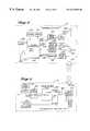
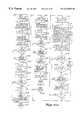
- FIG. 1is a block diagram illustrating the various modes of operation and interfacing equipment for the preferred embodiment of the telephone control system
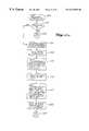
- FIG. 2is a block diagram illustrating the principle components of the telephone control system
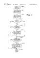
- FIG. 3is a block diagram of the Communicator
- FIG. 4is a block diagram of the Ultrasonic Transmitter
- FIG. 5is a block diagram of the Call Processing facility
- FIG. 6is a flowchart illustrating operation of the E & M Control Circuit
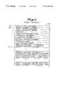
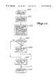
- FIG. 7is a diagram illustrating the Subscriber Master Record
- FIG. 8is a diagram illustrating the Mode Memory
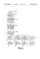
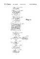
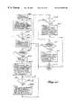
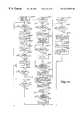
- FIG. 9is a flowchart of the Main Task for the Call Processing facility
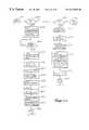
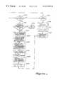
- FIG. 10is flowchart of the Code Processing Facility—Network Message Task
- FIG. 11is a flowchart of the Code Processing Facility—Call Termination Task
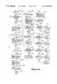
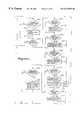
- FIGS. 12 a and 12 bform a flowchart of the Call Processing Facility—Call Handler Task;
- FIG. 13is a flowchart of the Call Processing Facility—Dynamic Mode Assignment
- FIGS. 14 and 14 aform a flowchart of the Call Processing Facility—Direct Forwarding Function
- FIGS. 15 a and 15 bform a flowchart of the Call Processing Facility—Announced Forwarding Function
- FIG. 16is a flowchart of the Call Processing Facility—Priority/Urgent Screen Function
- FIG. 17is a flowchart of the Call Processing Facility—VIP Code screen Function
- FIG. 18is a flowchart of the Call Processing Facility—Branch Routing Function
- FIG. 19is a flowchart of the Call Processing Facility—Caller Message Center Function
- FIGS. 20 a , 20 a - 1 , 20 b and 20 cform a flowchart of the Call Processing Facility—Voice-Screen Function;
- FIGS. 21 a and 21 bform a flowchart of the Call Processing Facility—Meet Me Caller Function
- FIG. 22is a flowchart of the Call Processing Facility—‘Send Page’ Subroutine
- FIGS. 23 a and 23 bform a flowchart of the Call Processing Facility—Command Mode Function
- FIG. 24is a flowchart of the Call Processing Facility—Command Message Center Function
- FIG, 25is a flowchart of the Call Processing Facility—Command Forwarding Number Function
- FIG. 26is a flowchart of the Call Processing Facility—Command Feature Timer Function
- FIG. 27is a flowchart of the Call Processing Facility—Command Memory Function
- FIG. 28is a flowchart of the Call Processing Facility—Command Outside Call Function
- FIG. 29is a flowchart of the Call Processing Facility—Command Help Function
- FIG. 30is a flowchart of the Call Processing Facility—Command Meet Me Function
- FIGS. 31 and 31 aform a flowchart of the Call Processing Facility—Command Branch Route Function
- FIG. 32is a flowchart of the Call Processing Facility—Command Advanced Features Function
- FIG. 33is a block diagram illustrating the principle components of the Meet Me Facility
- FIG. 34is a flowchart of the Meet Me Facility Main Task
- FIG. 35is a block diagram illustrating the principle components of the Subscriber Access Facility
- FIG. 36is a flowchart illustrating operation of the E & M Control Circuit for the Subscriber Access Facility
- FIGS. 37 a , 37 b and 37 b - 1form a flowchart of the Subscriber Access Facility Main Task
- FIG. 38is a block diagram illustrating the principle components of the Communicator Access Facility
- FIG. 39is a flowchart of the Communicator Access Facility Main Task
- FIGS. 40 and 40 aform a flowchart of the Communicator Main Task
- FIG. 41is a block diagram illustrating the principle components of the Pager Dialing Facility
- FIG. 42is a flowchart of the Pager Dialing Facility Main Task
- FIG. 43is a block diagram illustrating the principle components of the Client Services Facility.
- FIG. 44is a flowchart of the Client Services Facility Main Task.
- FIG. 1illustrates in block diagram form, the manner in which the Telephone Control System may be used to enhance the accessibility of it's subscribers.
- the Telephone Control System 1connects with the PSTN 2 via Facilities 3 .
- the Telephone Control System 1may control switch 4 , causing it to connect incoming and outgoing trunks.
- switch 4As is shown, alternate preferred embodiments exist with respect to switch 4 .
- the switch 4is actually part of the PSTN 1 .
- the facilities 3must be capable of transmitting switch control signals from the Telephone Control System 1 to the switch 4 .
- An example of this type of facilityis a CENTREX line, which allows the transmission of switch control signals in the form of ‘hookswitch flashes’ and touch tones to initiate call-conferencing and call-transfer.
- a recently available variation of the CENTREX facilityis a CENTREX DID trunk, which not only has the ‘hookflash’ capability, but also provides the called number in the form of Direct-Inward-Dialing digits. This is the form of facility 3 which is referred to in the detailed description of the preferred embodiment.
- Another variation of the CENTREX facilityprovides the called number via a separate data-link as Simplified Message Desk Interface (SMDI).
- SMDISimplified Message Desk Interface
- the switch 4is part of the Telephone Control System 1 .
- the facilities 3need only include standard DID trunks for the incoming calls, and standard outgoing trunks.
- the access control system 1controls switch 4 directly, causing it to connect paths between various incoming and outgoing trunks as required.
- the Telephone Control System 1also connects to the PSTN 2 via standard tip-ring phone lines 5 , for purposes of communicating with Paging System 6 .
- the Paging Systemmay be any of the commonly known paging systems such as those comprised of transmitters such as Motorola's PACE or Quintron model QT250B and paging terminals such as Glenayre model GL3000XL or BBL System 3 , which send encoded messages via radio frequency to cause a unique pager, or beeper, worn by a paging system subscriber, to sound an alert, produce a message in a display, activate a light, vibrate, or produce any of a variety of other alerting mechanisms.
- these paging systemswill cause a pager to be alerted in response to another individual dialing a phone number which corresponds to that individual's pager.
- This phone numberis routed via the PSTN 2 to a paging terminal via facilities 7 , which in turn determines, typically via DID digits, who the call is intended for, and then sends a radio frequency message to alert that individual's pager.
- the Telephone Control System 1then need only come off hook on one of the lines 5 , and dial the phone number that corresponds to the subscriber's pager.
- the Telephone Control System 1could also interface to a paging system directly via a dedicated data link.
- An additional facility 5connects the Telephone Control System 1 to the PSTN 2 .
- This facilityis a trunk which provides the Automatic Number Identification (ANI) of the calling party.
- ANIAutomatic Number Identification
- An example of such a trunkis the Feature Group D (FGD) trunk which is commonly used by interexchange carriers. The interexchange carriers use the ANI information to properly bill the calling party.
- the Telephone Control System 1uses this ANI information in a new and different manner.
- subscribers of the Telephone Control System 1may program the Telephone Control System 1 by calling it through trunking facilities 5 .
- the access control system 1automatically acquires the ANI, or phone number of the calling party. This allows the access control system 1 to program the forwarding number for the subscriber without the subscriber needing to manually enter it.
- An example of another type of facility which provides ANIis a CENTREX line with an SMDI data link, which is now available from several types of central offices.
- the SMDI data linkis capable of passing both the called party number and the calling party number (ANI).
- the Telephone Control System 1is also connected to a Packet Radio Transmitter/Receiver 9 via data-link 10 .
- the Packet Radio Transmitter/Receiver 9may consist of any of the commonly known radio transceivers such as YAESU FT-470 and 1 COM IC-u 4AT, equipped with a packet radio interface such as HEATHKIT HK-21.
- the Packet Radio Transmitter/Receiver 9is used by the Telephone Control System 1 to interface. with the portable Communicator device 11 , carried by an Telephone Control System subscriber.
- the Communicator 11may both send and receive DATA messages via radio frequency.
- the Communicator 11may also receive ultrasonic messages from fixed ultrasonic transmitter 12 , shown located in room 13 .
- Ultrasonic transmitter 12continuously transmits the phone number, and, if appropriate, the extension, of the phone 14 located in the same room or a signal indicating an appropriate call control mode for a given situation such as do not disturb in a hospital operating room.
- transmitter 12is anticipated that an infrared transmitter may also be used.
- the ultrasonic transmitterhas the advantage that it will pass signals through a layer of clothes, which would be important for example if the subscriber were carrying the Communicator 11 in a shirt pocket.
- FIG. 1also shows a subscriber's home 15 , with a home phone 16 ; a subscriber's office 17 , with an office phone 18 ; a cellular telephone system 19 , which interfaces to a subscriber's car-phone 20 ; a factory 21 , with a factory phone 22 ; a pay telephone 23 ; a subscriber 24 with pager 25 ; and a caller's telephone 26 .
- the greetingsinclude the phrase “ACCESSLINE”. It should be understood that the phrase “ACCESSLINE” is a registered trademark of AccessLine Technologies, Inc., and therefore those practicing the present invention will need to select alternate terminology if they are not licensed to use that phrase.
- a caller at phone 26wishes to speak to a subscriber to the access control system 1 , and further assume that the subscriber is at home 15 , and that he has preprogrammed the system to ‘direct forward’ his calls to him at his home phone 16 .
- the callerdials the access number for the subscriber, and the PSTN delivers the call to the Telephone Control System 1 via facilities 3 .
- the facilities 3provide the access control system 1 with the called party information (DID) digits.
- the Telephone Control Systemthen refers to it's internal database to determine how to handle the call.
- the access control systemdetermines that calls for this subscriber are to be handled via ‘direct forwarding’ mode, and that the call is to be forwarded to the subscriber's home.
- the access control systemthen dials the subscriber's home on an outgoing facility 3 , and instructs the switch 4 to connect the incoming facility to the outgoing facility to complete the call.
- the PSTN 2then delivers the call to home phone 16 , causing it to ring, and the subscriber may pick up the phone and connect to the caller. Note that this mode of call-handling is referred to as ‘direct forwarding’ because the call is forwarded without any announcement or prompting from the Telephone Control System 1 .
- a caller at phone 26wishes to speak to a subscriber to the Telephone Control System 1 .
- the subscriberis at home 15 , and that this time he has preprogrammed the system to ‘Announce-forward’ his calls to him at his home phone 16 .
- the callerdials the access number for the subscriber, and the PSTN delivers the call to the Telephone Control System 1 via facilities 3 .
- the Telephone Control System 1determines that calls for this subscriber are to be handled via ‘announced forwarding’ mode, and that the call is to be forwarded to the subscriber's home.
- the access control systemthen plays a brief greeting to the caller: “Hello, you have reached the **ACCESSLINE** for Mr. Jones. We're Connecting your call.”
- the Telephone Control Systemthen dials the phone number for phone 16 on an outgoing facility 3 , and instructs the switch 4 to connect the incoming facility to the outgoing facility to complete the call.
- the PSTN 2then delivers the call to home phone 16 , causing it to ring, and the subscriber may pick up the phone and connect to the caller.
- a caller at phone 26wishes to speak to a subscriber to the Telephone Control System 1 .
- the subscriberis at home 15 , and that this time he has preprogrammed the system to ‘Forward with page’ his calls to him at his home phone 16 .
- the callerdials the access number for the subscriber, and the PSTN delivers the call to the Telephone Control System 1 via facilities 3 .
- the access control system 1determines that calls for this subscriber are to be handled via ‘forward with page’ mode, and that the call is to be forwarded to the subscriber's home.
- the access control systemthen plays a brief greeting to the caller: “Hello, you have reached the **ACCESSLINE** for Mr.
- the Telephone Control System 1then dials the phone number for the pager corresponding to this subscriber and informs the caller “We have sent a page to alert your party and will connect you momentarily.”
- the access control systemthen dials the phone number for phone 16 on an outgoing facility 3 , and instructs the switch 4 to connect the incoming facility to the outgoing facility to complete the call.
- the PSTN 2then delivers the call to home phone 16 , causing it to ring, and the subscriber may pick up the phone and connect to the caller. The subscriber, having been alerted to the incoming call by his pager, was ready to receive it.
- the subscribermay not be able to take calls and may wish that his callers simply leave a message.
- the subscribermay program the access control system 1 to connect calls to the subscriber's preselected ‘message center’.
- the Telephone Control System 1may connect calls to either an ‘internal message center’ or an ‘external message center’.
- the ‘external message center’is simply a phone number that the Telephone Control System 1 will forward calls to if in this mode. This may be the phone number for an answering service, a receptionist, a voice mail system, or any other appropriate location as desired by the subscriber. If the subscriber elects to use the ‘internal message center’, then an example of a typical call may be as follows.
- a caller at phone 26wishes to speak to a subscriber to the Telephone Control System 1 .
- the subscriberdoes not wish to be disturbed and that he has programmed the system to ‘internal message center’ mode.
- the callerdials the access number for the subscriber, and the PSTN delivers the call to the Telephone Control System 1 via facilities 3 .
- the Telephone Control System 1determines that calls for this subscriber are to be handled via ‘internal message center’ mode.
- the Telephone Control Systemthen plays a brief greeting to the caller: “Hello, you have reached the **ACCESSLINE** for Mr. Jones.
- the Telephone Control System 1then records the callers message and saves it for later playback by the subscriber. In addition, should the subscriber have so elected, the access control system 1 may dial the phone number corresponding to the subscriber's pager, to alert the subscriber to the message.
- a caller at phone 26wishes to speak to a subscriber to the Telephone Control System 1 .
- the subscriberis at his office 17 , and that he has preprogrammed the system to send his calls to him at his office via ‘priority call-screening’, with a message asking the caller to ask for extension 123, which in this example is the extension number of the phone 18 on his desk.
- extension 123which in this example is the extension number of the phone 18 on his desk.
- the caller at phone 26dials the access number for the subscriber, and the PSTN 2 delivers the call to the access control system 1 via facilities 3 .
- the Telephone Control System 1determines that calls for this subscriber are to be handled via ‘priority call-screening’ mode, and that the call is to be forwarded to the subscriber's office. The access control system 1 then plays a brief greeting to the caller: “Hello, you have reached the **ACCESSLINE** for Mr. Jones. Your party is not readily available at the moment. If this call is urgent then please touch 0 now and we will attempt to connect you to your party. Otherwise, please hold the line and we will connect you to your party's message center where you may leave a detailed message.” If the caller does not touch 0, then the call is delivered to the ‘message center’ as described above.
- the Telephone Control System 1may inform the caller: “Please standby while we connect your call. When the call is answered please ask for extension number 123.”
- the access control systemthen dials the preprogrammed lead phone number for the subscriber's office 17 on an outgoing facility 3 , and instructs the switch 4 to connect the incoming facility to the outgoing facility to complete the call.
- the PSTN 2then delivers the call to the receptionist at office 17 , causing it to ring.
- the receptionist answersthe caller will ask for extension 123 , as he was instructed by access control system 1 , and the receptionist may connect the call to the subscriber's desk phone 18 .
- a caller at phone 26wishes to speak to a subscriber to the Telephone Control System 1 .
- the subscriberis in his car, and that he has preprogrammed the system to send his calls to him at his car-phone 20 via ‘VIP code-screening’.
- VIP code-screeningIn this mode, only those callers who have been told a special VIP code will be able to reach the subscriber. All other callers will be sent to the message center.
- the caller at phone 26dials the access number for the subscriber, and the PSTN 2 delivers the call to the Telephone Control System 1 via facilities 3 .
- the access control system 1Upon receiving the DID digits for this subscriber, the access control system 1 determines that calls for this subscriber are to be handled via ‘VIP code-screening’ mode, and that the call is to be forwarded to the subscriber's car phone 20 .
- the Telephone Control System 1then plays a brief greeting to the caller: “Hello, you have reached the **ACCESSLINE** for Mr. Jones. Your party is not readily available at the moment. Please enter your VIP code now, or hold the line and we will connect you to your party's message center where you may leave a detailed message.” If the caller does not enter the correct VIP code, then the call is delivered to the ‘message center’ as described above.
- the Telephone Control System 1may inform the caller: “Please standby while we connect your call.”
- the Telephone Control Systemthen dials the telephone number for car-phone 20 on an outgoing facility 3 , and instructs the switch 4 to connect the incoming facility to the outgoing facility to complete the call.
- the PSTN 2then delivers the call to the cellular telephone system 19 , which in turn delivers the call to the car-phone 20 .
- a caller at phone 26wishes to speak to a subscriber of the Telephone Control System 1 .
- the subscriberMr. Jones
- the caller at phone 26dials the access number for the subscriber, and the PSTN 2 delivers the call to the access control system 1 via facilities 3 .
- the Telephone Control System 1determines that calls for this subscriber are to be handled via ‘voice-screening’ mode, and that the call is to be forwarded to his client's factory 21 .
- the access control system 1then plays a brief greeting to the caller: “Hello, you have reached the **ACCESSLINE** for Mr. Jones. Please state your name and the purpose of your call at the tone. After the tone, please stay on the line while we attempt to locate your party and connect your call.”
- the access control system 1then records the caller's name and business, and then responds: “Thank you, please standby.”
- the access control systemthen dials the telephone number for factory 21 on an outgoing facility 3 , leaving the incoming call on hold.
- the PSTN 2then delivers the outgoing call to the lead telephone number of factory 21 , which is answered by the factory's receptionist.
- the Telephone Control Systemtells the receptionist “We have a call holding for Mr. Jones. Please locate the party.” The receptionist pages Mr.
- Mr. Jonesvia the factory's speaker system, informing him of the call. Mr. Jones then answers the call at phone 22 , and enters his Personal Identification Number (PIN) code. The access control system 1 then plays back the callers name and business. The Telephone Control System 1 then asks Mr. Jones: “Please touch 1 to connect the call, 2 to send the caller away, or 3 to send the caller to your message center.” In this example, Mr. Jones wishes to speak to the caller, so he touches 1. The Telephone Control System 1 instructs the switch 4 to connect the incoming facility to the outgoing facility to complete the call.
- PINPersonal Identification Number
- a caller at phone 26wishes to speak to a subscriber of the Telephone Control System 1 .
- the subscriberis not a person, but a business; the ABC Factory Company 21 , and that the Telephone Control System 1 has been preprogrammed to handle their calls via ‘branch-routing’ mode.
- the caller at phone 26dials the access number for the subscriber, and the PSTN 2 delivers the call to the Telephone Control System 1 via facilities 3 .
- the Telephone Control System 1determines that calls for this subscriber are to be handled via ‘branch-routing’ mode.
- the Telephone Control System 1then refers to it's memory and plays a pre-recorded ‘branch-routing’ greeting to the caller: “Hello, you have reached the ABC Factory Company. Please touch 1 to speak to the manufacturing manager, 2 to speak to accounts receivable, 3 to speak to accounts payable, 4 to speak to purchasing, or hold the line to speak to the receptionist.” Should the caller need help, he will hold the line for a moment, and the Telephone Control System 1 responds: “Please standby.” The Telephone Control System then dials the telephone number for the factory's reception phone 22 on an outgoing facility 3 , and instructs the switch 4 to connect the incoming facility to the outgoing facility to complete the call.
- a caller at phone 26wishes to speak to a subscriber to the Telephone Control System 1 .
- the subscriberMr. Jones
- the PSTN 2delivers the call to the Telephone Control System 1 via facilities 3 .
- the Telephone Control System 1determines that calls for this subscriber are to be handled via ‘meet-me’ mode.
- the Telephone Control System 1then responds by producing audible ringback to the caller, while dialing the phone number for the pager corresponding to this subscriber on facilities 5 .
- the Telephone Control System 1then plays a brief message to the caller: “Hello, you have reached the **ACCESSLINE** for Mr. Jones. We are paging your party to a phone, please standby. If you are unable to wait you may touch 9 to leave a message. Otherwise please hold the line.”
- the Telephone Control System 1then places the caller on hold and waits for the subscriber to call in. Meanwhile the subscriber 24 has received the page via his pager 25 , and is proceeding to pay phone 23 to answer the call.
- the subscriberdials his own access number and the PSTN 2 delivers the call to the Telephone Control System 1 via facilities 3 .
- the subscriberthen enters his own PIN code and is informed “You have a caller holding for you on your meet-me service.
- the access control system 1instructs the switch 4 to connect the incoming facility to the outgoing facility to complete the call.
- the access control systememploys a variety of different methods to allow the subscriber to easily and effectively program the operation of the Telephone Control System. Following are several illustrative examples of the various methods a subscriber may employ to program the Telephone Control System 1 .
- the subscriberTo use the Command Mode method of programming, the subscriber simply dials his own access number from any telephone, and enters his PIN code.
- the PSTN 2delivers the call to the Telephone Control System 1 via facilities 3 .
- the Telephone Control System 1then informs the caller of the current feature which is selected, and then provides the subscriber with a simple menu of options by which he can chose a new feature. For example, in response to the entry of the PIN code, the subscriber may be prompted: “Hello Mr. Jones. Your calls are currently being VIP code screened to your office. Touch 1 to check messages, 2 to change your forwarding number, 3 to select a memory, 8 for advanced features, 9 to make a call, or touch 0 for help.” The subscriber may then make his desired selection.
- Telephone Control System Command Modeallows the subscriber to program ‘mode memories’ which contain the most often used call handling methods for that subscriber. For example, a subscriber may program memory 10 to be announced forwarding to his office, memory 20 to be voice screened forwarding to his home, memory 30 to be message center mode, and so forth.
- the weekly schedule featureprovides a very real benefit to the subscriber.
- a subscriberMr. Jones
- the weekly schedule for this subscribermight be pre-programmed into the Telephone Control System's database to be:
- the Telephone Control System 1refers to this database and determines the correct call handling method for the day of week and time of day, and delivers the call accordingly.
- Another feature of the weekly scheduleallows the subscriber to override the weekly schedule should his schedule deviate from the preprogrammed sequence. In this way the subscriber can move freely about his routine activites, and only he needs to program the access control system should his schedule change from the normal.
- Feature Timer capability of the Telephone Control SystemTo illustrate the use of the Feature Timer capability of the Telephone Control System, assume that a subscriber is visiting a client's office for a one hour appointment, and wishes to have his calls forwarded to him at this location during that time. He may use the Command Mode as described above to select announced forwarding mode and change the forwarding number to be the telephone number of his client's phone. When he leaves he intends to change the the call handling mode back to his message center. However, if the subscriber forgets to call the Telephone Control System as he is leaving the client's office, then the client may still continue to receive calls intended for the subscriber. To overcome this problem, the subscriber may have instead used the Feature Timer function when he first called the access control system when he got to the client's office.
- the subscribercould have called the access control system, and used Command Mode to select announced forwarding to his client's office. However, instead of hanging up at that point, he could have activated the Feature Timer, programming it to maintain the current mode for one hour and then automatically change the call handling mode to message center mode. In this way, the subscriber would not have to remember to call the Telephone Control System as he leaves the client's office, and the client would not be bothered with the subscriber's calls after he left.
- One difficulty in prior art implementations of remotely programmable call forwarding devicesis that it takes quite a few digits for the user to call the system, enter an access code, and then enter the forwarding number.
- One means by which the invention described herein overcomes this difficultyis by employing special trunks which provide the called party number, also referred to as ANI. To see how this improves the ease of programming, consider the following example. Assume that the subscriber is visiting factory 21 , and that this is a location that he does not visit regularly, and therefore does not have it's telephone number preprogrammed into the Telephone Control System 1 .
- the access control system 1is connected to the PSTN with Feature Group D trunks 8 which provide ANI, and which can be reached by dialing an 800 number.
- the subscriber in this examplewould pick up telephone 22 and dial the 800 number which corresponds to the Feature Group D trunk.
- the PSTN 2would deliver the call to the Telephone Control System 1 and the Telephone Control System 1 would receive the ANI information digits containing the telephone number of telephone 22 .
- the subscriberthen need only enter his PIN code and the call handling feature memory he wishes to use, which might be memory 40 , announced forwarding.
- the subscribercould then hang up and the Telephone Control system 1 would program the database to send all calls for that subscriber to telephone 22 via announced forwarding.
- a well known service offered by many telephone companiesis ‘Speed Calling’. This service allows users to preprogram often used telephone numbers into memories which can be recalled by dialing a one, two, or three digit code.
- This serviceallows users to preprogram often used telephone numbers into memories which can be recalled by dialing a one, two, or three digit code.
- To see how subscribers can use this service to improve the ease of programming the Telephone Control Systemconsider the following example. Assume that an Telephone Control System subscriber, who lives at home 15 , has preprogrammed the access control system with his home phone number 16 . Let us further assume, as was discussed earlier, that the Telephone Control System 1 is connected to the PSTN 2 with Feature Group D trunks 8 which provide ANI, and which can be reached by dialing an 800 number, and assume further that an entire 800-NNX has been dedicated to this trunk group, in this example 800-999-XXXX.
- the last four digits of the 800 numberwill be used to signify the mode memory which is being selected.
- the subscriberhas preprogrammed his telco speed dialing feature so that the sequence 2# causes the telephone number 1-800-999-0010 to be dialed, and that the sequence 3# causes the telephone number 1-800-999-0011 to be dialed.
- the speed dialing featurewill cause the number 1-800-999-0010 to be dialed.
- the PSTN 2will deliver the call to the access control system 1 via Feature Group D trunks 8 .
- the access control system 1will receive the ANI digits, and referring to it's database recognize the call as originating at the home telephone of one of it's subscribers. It then will invoke the preprogrammed mode memory 10 for that subscriber, which in this example might be voice-screened forwarding to his home phone. As a further example, if the subscriber had dialed 3#, the Telephone Control System 1 would have invoked memory 11 for that subscriber.
- the Communicatoris a portable device carried on the subscriber's person.
- This exampledemonstrates some of the ways by which the Communicator can simplify the call handling and programming operations for the Telephone Control System subscriber.
- the subscriberis carrying a communicator 11 on his belt, and that he has just entered room 13 .
- the Communicator 11detects a signal from the fixed ultrasonic transmitter 12 located near the ceiling. This signal is decoded by the Communicator 11 and is determined to contain a phone number, which in this example happens to correspond to the phone instrument 14 located in the same room 13 .
- the Communicator 11Upon receipt of the ultrasonic signal, the Communicator 11 transmits a brief packet message via radio frequency. This message contains the subscriber's access number and the phone number just received form the ultrasonic transmitter 12 . This radio frequency message is detected by packet radio transceiver 9 and passed on to the access control system 1 via data link 10 . The Telephone Control System 1 then changes the forwarding number for this subscriber to be the new number.
- a caller at phone 26wishes to speak to this subscriber.
- the callerdials the access number for the subscriber, and the PSTN delivers the call to the access control system 1 via facilities 3 .
- the Telephone Control System 1determines that calls for this subscriber are to be handled via ‘direct forwarding’ mode, and that the call is to be forwarded to the subscriber at telephone 14 .
- the access control system 1then sends a page message to the packet radio transceiver 9 via data-link 10 .
- the packet radio transceiver 9in turn transmits a radio frequency packet message to Communicator 11 , causing the beeper in the Communicator 11 to alert the subscriber to the incoming call.
- the Communicator 11may also then send an acknowledgment message back via radio frequency to the packet radio transceiver 9 .
- the Telephone Control System 1has begun to dial the phone number for phone 14 on an outgoing facility 3 , and instructs the switch 4 to connect the incoming facility to the outgoing facility to complete the call.
- the PSTN 2then delivers the call to phone 14 , causing it to ring, and the subscriber may pick up the phone and connect to the caller.
- the subscribercompletes the call and leaves the room 13 .
- Communicator 11detects the loss of signal from ultrasonic transmitter 12 , and realizes therefore that the subscriber has left the room and is no longer able to receive calls at this location.
- the Communicator 11then transmits a brief packet message via radio frequency.
- This messagecontains the subscriber's access number and a special message indicating that no phone number is available and that a default mode memory is to be used for call handling.
- This radio frequency messageis detected by packet radio transceiver 9 and passed on to the Telephone Control System 1 via data link 10 .
- the Telephone Control System 1then changes the method of call handling for this subscriber to the default mode, which may typically be message center mode. It should be obvious now that if the subscriber were to reenter room 13 , or to enter another room with a similar ultrasonic transmitter, that a similar sequence of events would occur causing the calls for this subscriber to be routed to the appropriate room. In this way, without any specific action or effort on the part of the subscriber, his calls will follow him from location to location and be handled automatically and properly.
- Another feature of the Communicatorallows the subscriber to enter a ‘manual phone number’ mode whereby the Communicator will ignore the messages received from the ultrasonic transmitters, maintaining the last used mode or forwarding number.
- Another feature of the Communicatorallows the subscriber to select a new method of call-handling by touching keys on the Communicator's keypad. This will cause the Communicator 11 to transmit a ‘new mode memory request’ packet message via radio frequency to the packet radio transceiver, which in turn will send the message to Telephone Control System 1 via data-link 10 , causing the Telephone Control System 1 to change the call handling method for that subscriber.
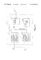
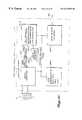
- FIG. 2is a block diagram of the telephone control system 1 .
- the preferred embodiment of the telephone control system 1consists of a variety of subsystems, or facilities.
- a Call Processing Facility (CPF) 100is shown connected to trunks 3 .
- a Pager Dialing Facility (PDF) 105is shown connected to telephone lines 5 .
- a Subscriber Access Facility (SAF) 110is shown connected to trunks 8 .
- a Meet-Me Facility (MMF) 115is shown connected to lines 120 .
- a Communicator Access Facility (CAF) 125is shown connected to datalink 10 .
- a Client Services Facility (CSF) 130is also shown. Each of these facilities is connected to high speed data network 150 .
- FIG. 3A block diagram of the Communicator 11 is shown in FIG. 3 .
- the operation of the Communicator 11is controlled by microprocessor 200 , which in the preferred embodiment is a single chip microprocessor containing it's own Read-Only-Memory (ROM) and Random-Access-Memory (RAM).
- ROMRead-Only-Memory
- RAMRandom-Access-Memory
- a keypad 205 , and display 210are shown connected to microprocessor 10 .
- a transmit data output port 215is provided by the microprocessor 200 . This transmit data is passed to packet data encoder 220 which formats the data into packets before sending the packets to antenna 230 via radio frequency transmitter 225 .
- Radio frequency receiver 235receives data packets from antenna 230 and passes them to packet data decoder 240 , which removes the packet format and passes the raw received data to the receive data input port 245 on microprocessor 200 .
- Output port 250may be used to apply a tone signal to beeper driver 255 which supplies sufficient current to drive beeper 260 to produce an alerting sound.
- a transducer 265capable of receiving signals in the ultrasonic frequency range, passes these signals to a 40 Kilohertz filter and amplifier 270 . The resulting signal is applied to detector 275 which removes the 40 Kilohertz component from the signal and passes the resulting serial data to input port 280 of microprocessor 200 .
- a crystal oscillator 285which controls the timing of all operations of the microprocessor 200 .
- Power for the Communicator 11is supplied by battery 290 .
- Improvements that currently exist in the ARTmay be made to the ultrasonic transmitter and detector to enhance its ability to communicate the ultrasonic data in the presence of multi-path echoes. These improvements include, but are not limited to: frequency shift keying; the transmission of synchronized data and the use of a clock recovery logic to extract the clock timing over a long integration period resulting in a clock move resistant to echoes; the use of error detecting and correcting codes; and the use of sampling and voting techniques to determine the correct bit value after multiple samples during a bit period, the bit period being determined by the clock recovery logic above.
- multiple transmittersmay be used as a method of obtaining increased coverage and area transmission diversity.
- Oscillator 300provides a 40 Kilohertz signal to one input of AND gate 305 .
- the output of crystal oscillator 310is applied to divider 311 which produces a 75 Hertz signal to the clock input of 6-bit counter 315 .
- the 6 outputs of counter 315are applied to the address inputs of Read-Only-Memory 320 .
- Memory 320is pre-programmed with data representing the phone number of the nearest telephone. This data may contain the area code plus seven digits and the extension number if appropriate. With each digit represented by 4 bits, 14 digits and 8 bits of checksum may be transmitted.
- LSB output 325is used to apply this data to a second input of AND gate 305 .
- the serial data at 325will continuously output the- phone number at a rate of 75 bits per second.
- AND gate 305combines the serial data 325 and the 40 Kilohertz signal from oscillator 300 producing a resultant signal which is applied to transducer driver 330 .
- the output of driver 330is then applied to transducer 335 .
- the transducerwill be generating a 40 Kilohertz signal while the serial data output 325 is high, and will be generating no signal while the serial data output 325 is low.
- the datais therefore modulated on the 40 Kilohertz carrier at a rate of 75 baud.
- the 64 bits from the ROM 320are thus transmitted in a period of 0.853 seconds. This is adequate for the transmission of a phone number and extension.
- this baud rateis relatively low; it has the advantage of reducing the effect of multipath (reflections of the ultrasonic signal arriving at the receiver at different times and phases), and thus improves the reliability of transmission as compared with higher baud rates.
- FIG. 5A block diagram of the Call Processing Facility (CPF) 100 is shown in FIG. 5..
- CPF trunk interface 400interfaces the CPF 100 with trunk 3 .
- the preferred embodiment of the telephone control system 1employs a CENTREX DID trunk.
- trunk 3is provided via a 4-wire E&M trunk provisioned with TYPE I signalling, which is well known in the art.
- This type of trunkprovides a 2-wire balanced transmit audio connection, shown terminated by line termination 405 .
- This type of trunkalso provides a 2-wire balanced receive audio connection, shown terminated by line termination 410 .
- the E-Lead of trunk 3is shown connected to the current limiting and overvoltage protection at reference 415 .
- the M-Lead of trunk 3is shown connected to the current limiting and overvoltage protection at reference 420 .
- 2-to-4 wire convertor 425takes the separate balanced transmit and receive signals from line terminators 405 and 410 and combines them into one single-ended signal at reference 430 , which is applied to call processor 435 .
- the E-Lead signal from limiter/protector 415is passed to current detector 440 .
- current detector 440provides a path for the E-Lead signal through to the negative battery reference of ⁇ 48 volts at 445 .
- Current Detector 440also provides an “E-Lead Detect” logic signal indicating the presence of current via the E-lead.
- This signalis applied to E&M lead control circuit 450 .
- the M-Lead signal for limiter/protector 420is passed to M-Lead relay 455 .
- This relayis controlled by a “M-Lead Control” signal from control circuit 450 .
- control circuit 450By activating or deactivating relay 455 , control circuit 450 is able to take the M-Lead on-hook or off-hook, as the M-Lead will be connected either to ⁇ 48 volts or to ground.
- the control circuit 450outputs an “Incoming Call” signal 470 to buffer 460 , and outputs a “Loop Status” signal 475 to call processor 435 .
- the control circuit 450has as additional inputs a “DID Received” signal 480 from latch 465 , and an “On/Off-Hook Control” signal 485 from call processor 435 .
- the output of buffer 460 , and the input of latch 465is applied to CPF internal data bus 490 .
- the CPF internal data bus 490connects CPF trunk interface 400 , call processor 435 , precision busy/ring detector 437 , Central Processing Unit (CPU) 495 , Random Access Memory (RAM) 500 , Disk memory 505 , and data network interface 510 .
- Call processor 435performs the functions of voice record and playback, dual-tone-multi-frequency (DTMF) detection and generation, and call control.
- the functions of call processor 435are well known in the art and many products, such as the Model D41B manufactured by Dialogic Corporation, exist commercially which can accomplish these functions.
- a voice recognition module 436is shown connected to call processor 435 .
- Voice recognition module 436allows call processor 435 to detect, on a speaker-independent basis, a simple set of spoken commands from callers.
- the simple setconsists of 16 words including the digits ‘0’ through ‘9’.
- This capabilityin combination with the DTMF detection capability of the call processor 435 , allows caller to either speak their commands, or enter them from a DTMF phone.
- a commercially available product which performs this voice recognition functionis the Model VR/10 manufactured by Dialogic Corporation.
- a precision busy/ring detector 437is shown connected to the audio signal 430 from CPF trunk interface 400 .
- This detectormay be used to perform a rapid detection of precise busy and precise ringing signals, even in the presence of voice.
- precision busy/ring detector 437does not require a cadence match and is therefore capable of rapidly detecting precise busy and ringing signals even if a party is conferenced in and speaking on the line. This capability is useful in providing the ‘busy/no-answer option’ as will be described later.
- the functions of precise busy/ring detector 437are well known in the art, and may be typically implemented as follows.
- the incoming audio signalis applied to the inputs of several identical circuits, each with center frequencies set to detect a different component of the expected busy or ringing signal.
- Each of these circuitscontains a low Q bandpass filter. This filter prevents out-of-band signals such as voice from interfering with the detection function.
- the output of the bandpass filteris fed to a zero crossing detector.
- the output of the zero crossing detectoris then fed to a high Q bandpass filter again set at the frequency to be detected.
- the output of the bandpass filteris then sent to a level detector which provides a positive indication if the incoming signal is above a preset amplitude.
- the output of the busy/ring detector 437may be read by CPU 495 via the CPF internal data bus 490 .
- CPU 495controls all functions of CPF 100 .
- the software program which the CPU 100 usesis loaded into RAM 500 , from disk memory 505 .
- the disk 505also is used to store a variety of other data including the subscriber database for the telephone control system 1 .
- a data network interface 510is used to connect the CPF 100 to the other subsystems of the telephone control system 1 .
- Data network interface 510passes data messages between the CPU 495 and these other subsystems.
- the functions of data network interface 510are well known in the art, and many products, such as the Model COM4i from Digiboard Corporation, exist commercially which can accomplish these functions.
- Only one trunk interface 400 , one trunk 3 , and one call processor 435are shown in FIG. 5, it should be readily evident to one skilled in the art that additional trunk interfaces and call processors may be added to support additional trunks.
- FIG. 6A flowchart of the operation of E&M control circuit 450 is shown in FIG. 6 .
- the control circuit 450idles waiting for an indication from current detector 440 that the E-Lead has gone off-hook.
- an “Incoming Call” signalis sent to CPU 495 via buffer 460 .
- the control circuit 450then idles at 610 , waiting for an off-hook signal from call processor 435 , signifying that the CPU 495 is ready to accept the call.
- the “Loop Status” 475is set active as shown at reference 615 .
- the M-Leadis then winked by taking M-Lead relay 455 momentarily off-hook, as shown at reference 620 .
- the control circuit 450then idles again at 625 , waiting for the receipt of the “DID Received” signal 480 from CPU 495 via latch 465 .
- Call processor 435detects the incoming DID digits on it's audio line 430 and decodes the digits passing the digit sequence on to CPU 495 .
- This DID digit sequencerepresents the ‘called number’ or ACCESS NUMBER of a subscriber to the telephone control system 1 .
- the CPU 495When the CPU 495 receives the DID digits from call processor 435 , the CPU 495 sets the “DID Received” signal 480 active, and the control circuit 450 takes the M-Lead off-hook as shown at reference 630 . At this point a call has been established, and the control circuit 450 must now wait until either CPU 495 terminates the call, as signified by on/off-hook control signal 485 going on-hook, or by the calling party terminating the call as signified by the E-Lead detect from current detector 440 going on-hook. These functions are accomplished by control circuit. 450 as illustrated at references 635 through 670 . At 635 a check is made to determine if on/off-hook control signal 485 is on-hook.
- Controlthen returns to step 600 where the control circuit 450 restarts it's sequence at reference 600 .
- a 1.5 second timeris started as shown at reference 655 . This timer is used to distinguish between a ‘hookflash’ signal, which is typically less than 1.5 seconds, and an on hook command which should be at least 1.5 seconds.
- the control circuit 450causes the M-Lead relay 455 to place the M-Lead on-hook.
- a checkis made to determine if the 1.5 second timer has expired. If it has expired, then the signal was a true on-hook command, and control passes to reference 645 for the termination of the call.
- the subscriber master recordcontains information regarding a given subscriber's chosen method of call handling. This information is used by the Telephone Control System 1 to determine how to process the call.
- One unique subscriber master recordexists for each subscriber to the Telephone Control System 1 . All subscriber master records are stored in disk 505 and, upon initialization of the Telephone Control System 1 , are copied to a common database in RAM memory 500 by CPU 495 . This facilitates fast retrieval of this information, which is necessary for the real-time processing of calls to the access control system 1 .
- the subscriber master record 700contains as it's first element an access (DID) number, shown at reference 701 .
- this access number 701is the unique phone number which is used to reach a given subscriber via the Public Switched Telephone Network 2 .
- a PIN codewhich is used by the subscriber to identify himself to the Telephone Control System 1 , is shown at 702 .
- a call handling modeis shown. The call handling mode defines the basic method of call handling which has been chosen by the subscriber. Possible call handling modes include direct forwarding, announced forwarding, message center, voice screen forwarding, urgent screen forwarding, VIP code screen forwarding, and branch-routing.
- a standard greeting typeis shown.
- the standard greeting type, 704defines the courtesy greeting announcement which the subscriber has selected for the Telephone Control System 1 to use when first answering a call.
- an options fieldis shown. This options field is used to contain several miscellaneous option flags which may be used to modify the operation of the basic call handling mode. Options 705 include ‘page option’ which causes a page to be sent when a call is forwarded, an ‘emergency/urgent’ option which modifies the operation of the priority or urgent screen forwarding mode, a ‘busy/no-answer’ option which causes calls to be sent to the message center if a busy or no-answer condition is detected, and a voice screen hold off option which modifies the operation of the voice screen forwarding mode.
- a transfer message typeis shown at reference 706 .
- the transfer message type, 706defines the courtesy announcement which the subscriber has selected for the access control system 1 to use as a call is being transferred.
- a transfer numberis shown at 707 . This is the number which the access control system 1 will use when forwarding, or transferring calls for this subscriber.
- an extension numberis shown which may be used by the Telephone Control System 1 to a ounce to a caller the extension number of the phone at which the subscriber is located.
- the subscriber's message cater numberis shown stored at 709 .
- the subscriber's pager numberis shown stored at 710 .
- the subscriber's office numberis shown stored at 711 .
- the subscriber's home numberis shown stored at 712 .
- the subscriber's mobile phone numberis shown stored at 713 .
- a VIP screen codeis shown.
- the VIP screen codeis a code which may be used by a caller to cause his call to be forwarded to the subscriber, when the subscriber has selected VIP code screened forwarding mode.
- the number of the current feature memory which is being usedis shown stored at 715 .
- a pager message display numberis shown. This is the number which the subscriber wishes to appear in the display of his pager when the access control system 1 has taken a message from a caller.
- a pager forwarding display numberis shown. This is the number which the subscriber wishes to appear in the display of his pager when the Telephone Control System 1 is in the process of forwarding a call to the subscriber.
- a communicator dynamic mode display numberis shown. This is the number which the subscriber wishes to appear in the display of his communicator 11 when the Telephone Control System 1 has a call holding, and requires that the subscriber select a method of call handling to dispose of the call.
- the time and date that the last caller abandoned a meet-me call by hanging up without leaving a messageis shown stored at 719 .
- the time and date that the last caller abandoned a meet-me call by leaving a messageis shown stored at 720 .
- a count of the number of calls which have been transferred to an external message center by the Telephone Control System 1is shown stored at 721 . Shown generally at 722 are the branch routing numbers 0 through 9.
- These fieldscontain the phone numbers to which a call should be transferred if a caller touches one of the digits 0 to 9 when the access control system 1 is processing a call using branch-routing mode.
- the branch-routing default transfer numberis shown stored at 723 . This is the number to which the call is transferred should a caller not enter one of the digits 0 to 9.
- Shown stored at 724is the feature timer duration. This value determines when the feature timer expires.
- Shown stored at 725is the feature timer termination mode. This field contains the mode memory which the subscriber wishes to use upon expiration of the feature timer.
- the fields necessary to implement the weekly schedule functionare shown generally at reference 726 . In the preferred embodiment the weekly schedule may contain up to 32 events (steps).
- the subscriber master record 700stores a time and date, and a mode memory number to be used at that time and date.
- the current step number (1 to 32)is shown stored at 727 .
- a flag which indicates to Telephone Control System 1 that the weekly schedule is on,is shown stored at 728 .
- a flag which informs the Telephone Control System 1 as to whether the subscriber is allowed to make multiple outside callsis shown stored at 729 .
- a flag indicating that the subscriber has selected to use his communicator 11 in the ‘dynamic mode assignment’ modeis shown stored at 730 .
- a count of the number of calls made to this ACCESS NUMBERis shown stored at 731 .
- FIG. 8A diagram of a Mode Memory, reference 800 , is illustrated in FIG. 8 .
- the mode memoriesare used by subscribers of the Telephone Control System 1 to store their commonly used call handling modes and options.
- the mode memories 800are stored in disk 505 and, upon initialization of the Telephone Control System 1 , are copied to a common database in RAM memory 500 by CPU 495 .
- Each mode memoryis unique to an individual subscriber, and is identified by storing the subscriber's ACCESS NUMBER as part of the mode memory, as shown at reference 801 .
- the subscribermay have up to 90 mode memories.
- Each mode memoryis identified by a unique mode memory number, 10 through 99.
- This mode memory numberis shown stored as part of the mode memory 800 at reference 802 .
- Shown generally at reference 803are the various fields which the subscriber has selected to store in the mode memory 800 . As can be seen, these are a subset of the fields which are stored in the subscriber master record 700 .
- the Telephone Control System 1need only copy the fields from the mode memory 800 to the corresponding fields in the subscriber master record 700 .
- the access control system 1also copies the mode memory number 802 to the current feature memory field 715 of the subscriber master record 700 .
- FIG. 9A flowchart of the Main Task for the Call Processing Facility (CPF) 100 is shown in FIG. 9 .
- This flowchartrepresents the instructions, or steps, followed by CPU 495 , as it controls functions of CPF 100 .
- the starting point for the CPF—MAIN TASKis shown at reference 900 .
- the CPU 495performs initialization processes. These processes are well known in the art and include such activities as using a boot PROM to load the operational program from disk, checking for memory errors, performing hardware diagnostics, etc.
- the subscriber master records 700are read from disk 505 and copied to a database in memory 500 , as shown at step 902 .
- the mode memories 800are read from disk and copied to a database in memory, as shown at step 903 .
- the multitasking processesare established.
- the multitaskingallows the software to perform more than one process simultaneously.
- Multitasking techniquesare well known in the art. As an example, UNIX is a widely used multitasking operating system. Other well known techniques allow a pseudo-multitasking function to be accomplished on a non-UNIX based operating system by constructing a ‘round-robin’ scheduler, by which a main process allocates ‘time slices’ to each of a number of sub-processes.
- a process for the Network Message Taskis initialized, and at step 906 control is passed to the CPF—Network Message Task.
- a process for the Call Handler Task for the first trunk 3is initialized, and at step 908 control is passed to the CPF—Call Handler Task.
- a process for the Call Handler Task for the last trunk 3is initialized, and at step 910 control is passed to the CPF—Call Handler Task.
- a process for the Call Termination Taskis initialized, and at step 912 control is passed to the CPF—Call Termination Task.
- a flowchart of the CPF—Network Message Taskis illustrated in FIG. 10 .
- the function of this taskis to receive and process messages received by Data Network Interface 510 from other facilities of the access control system 1 .
- the CPF—Network Message Taskis entered at step 1000 .
- a determinationis made as to whether a “request master record” message has been received. If this message has been received, then at step 1002 the subscriber master record 700 which corresponds the DID number, ANI number, or PIN code provided in the message is searched for in the database of memory 500 .
- Upon finding this subscriber master recordat step 1003 a message containing a copy of this subscriber master record is sent back to the requesting facility via data network interface 510 . Control then returns to step 1000 .
- step 1004a check is made to determine if an “update master record” message has been received. If such a message has been received, then at step 1005 a master record for a subscriber is recovered from the message and copied to the the subscriber's master record 700 , at which point control returns to step 1000 . If an “update master record” message is not detected at step 1004 , then at step 1006 a check is made to determine if a “clear dynamic mode assignment flag” message has been received.
- step 1007If such a message has been received, and the message identifies a specific subscriber DID number, then the dynamic mode assignment flag 730 in the subscriber master record 700 for this subscriber is cleared at step 1007 , and control returns to step 1000 . If a “clear dynamic mode assignment flag” message is not detected at step 1006 , then at step 1008 a check is made to determine if a “set dynamic mode assignment flag” message has been received. If such a message has been received, and the message identifies a specific subscriber DID number, then the dynamic mode assignment flag 730 in the subscriber master record 700 for this subscriber is set at step 1009 , and control passes to step 1000 .
- a “set dynamic mode assignment flag” messageis not detected at step 1008 , then at step 1010 a check is made to determine if “change to new mode memory” message has been received. If such a message has not been received, then control passes to step 1014 . If such a message has been received, and the message identifies a specific subscriber DID number, then at step 1011 a check is made to determine if the message was sent by the Communicator Access Facility (CAF) 125 . If the message was not from the CAF 125 , then control passes to step 1013 . If the message was from the CAF 125 , then at step 1012 an indication is sent to the CPF—Dynamic Mode Assignment routine (shown in FIG.
- CAFCommunicator Access Facility
- step 1013the mode memory number and the subscriber's DID number are removed from the message, and the corresponding mode memory 800 is copied to the corresponding subscriber's subscriber master record 700 . Control then returns to step 1000 . If at step 1010 it is determined that a ‘change to new mode memory message’ is not received, then control passes to step 1014 , where a determination is made as to whether a ‘mode memory inquiry’ message is received, and if this is the case then control passes to step 1015 where the mode memory 800 identified in the message for the subscriber identified in the message is retrieved from the database of memory 500 and a message is constructed and sent back to the requesting facility via data network interface 510 .
- Controlthen returns to step 1001 . If at step 1014 it is determined that a ‘mode memory inquiry message is not received, then control passes to step 1016 , where a determination is made as to whether a ‘mode memory update’ message is received, and if this is the case, then control passes to step 1017 where the new mode memory contents are retrieved from the message, and the mode memory is copied to the appropriate mode memory 800 in the database of memory 500 . Control then returns to step 1001 .
- FIG. 11A flowchart of the CPF—Call Termination Task is illustrated in FIG. 11 .
- the purpose of this taskis to monitor the loop status signal 475 for each trunk interface 400 , and to terminate any call in progress should the loop status become inactive. In this way the system detects if the calling party has hung up.
- the CPF—Call Termination Taskis entered at step 1100 .
- a trunk pointeris set to a value of 1.
- the loop status signal 475 for the trunk pointed to by the trunk pointeris read via call processor 435 .
- a determinationis made as to whether the loop status signal 475 is active. If the signal is active, then control passes to step 1106 .
- step 1108a determination is made as to whether this trunk was processing the “CPF-Meet Me Caller” function, and if this is the case then control passes to step 1109 where the current time and date is stored in the “last meet-me abandon” field 719 of the subscriber master record 700 . Control then passes to step 1105 . Control also passes to step 1105 if at step 1108 it is determined that the trunk was not processing the “CPF-Meet Me Caller” function.
- this CPU 495signals the multitasking process 907 controlling the call handler task for this trunk to return to it's entry point 908 , thereby terminating any activity on that trunk.
- Controlthen passes to step 1106 , where a check is made to determine if the trunk pointer is pointing to the last trunk. If the trunk pointer is pointing to the last trunk, then control returns to step 1101 . If the trunk pointer is not pointing to the last trunk, then at step 1107 the trunk pointer is incremented and control returns to step 1102 .
- FIGS. 12 a and 12 bA flowchart of the CPF—Call Handler Task is illustrated in FIGS. 12 a and 12 b .
- the function of this taskis to respond to an incoming call on a trunk 3 , receive the DID digits identifying the subscriber's ACCESS NUMBER being dialed, determine the method of call handling as specified in the database of memory 500 by subscriber master record 700 which corresponds to that ACCESS NUMBER, and then cause the call to be processed accordingly.
- the CPF—Call Handler Taskis entered at step 1200 , a connection point labelled “CPF IDLE” is passed at reference 1201 , and at step 1202 the DID received signal 480 is cleared, allowing trunk interface 400 to receive a new call.
- CPF IDLEconnection point labelled “CPF IDLE”
- Controlthen remains at step 1203 until an incoming call signal 470 is received from the trunk interface 400 , at which point control passes to step 1204 causing the call processor to issue an off hook signal via it's on/off hook control line 485 .
- incoming DID digitsare decoded and accepted by the DTMF detector of call processor 435 .
- the DID received signal 480is set, causing E & M control circuit 450 to force the M-Lead active, thereby seizing the trunk.
- Controlthen passes through a connection point labelled “CPF VIRTUAL TRANSFER” at reference 1207 .
- the subscriber master record 700 which corresponds to the received DID numberis retrieved from the database of memory 500 .
- the call count 731is incremented in the subscriber master record 700 .
- a checkis made to determine if the feature timer is active. This is accomplished by checking the feature timer duration 724 . The feature timer is active if the feature timer duration 724 is non zero. If the feature timer is not active, then control passes to step 1213 . If the feature is active, then another check is made at step 1211 to determine if the feature timer has expired since the last call. This is determined by comparing the feature timer duration 724 with the current time and date maintained by CPU 495 .
- the feature timerhas expired if the feature timer duration 724 does not extend beyond the current time and date. If the feature timer has not expired, then control passes to step 1213 . If the feature timer has expired, then at step 1212 the mode memory 800 specified by the feature timer termination mode 725 is copied to the subscriber master record 800 , and the feature timer duration 724 is cleared to zero. Control then passes to step 1213 . A determination is made at step 1213 as to whether the weekly schedule is active by checking the status of the weekly schedule active flag 728 . If the weekly schedule is not active, then control passes to step 1217 . If the weekly schedule is active, then a determination is made a step 1214 as to whether the current step of the weekly schedule is correct.
- step 1217This is accomplished by finding the current step of weekly schedule 726 as pointed to by the weekly schedule current step 727 , and comparing the time and date of the next step with the current time and date. If the current time and date fall between the current step and the next step, then the current step is correct. If, by this process, it is determined that the current step is correct, then control passes to step 1217 . Otherwise, at step 1215 , the weekly schedule current step 727 is incremented to point to the next step. Then at step 1216 , the mode memory number corresponding to the new step of the weekly schedule 726 is found, the corresponding mode memory 800 is copied to the subscriber master record 700 , and then control passes to step 1217 .
- step 1217the status of the dynamic mode assignment flag 730 is checked, and if it is found to be active, control is passed at step 1218 to the CPF—Dynamic Mode Assignment. otherwise, control passes through a connector labelled “CPF MODE” at reference 1219 , and then passes to step 1220 .
- step 1220a determination is made as to whether the current call handling mode 703 is set for ‘direct forwarding’, and if so control is passed via step 1221 to the CPF—Direct forwarding. Otherwise a determination is made at step 1222 as to whether the current call handling mode 703 is set for ‘announced forwarding’ and if not control passes to step 1230 .
- step 1223a further check is made to determine if the transfer number 707 is set for meet-me, and if not control passes to step 1230 . If the transfer number 707 is set for meet-me, then at step 1224 one audible ring is played to the caller by call processor 435 . Then at step 1225 , the ‘pager display digits’ are set to be equal to the DID number, prior to the “send page” subroutine being called at step 1226 . Upon receiving a page with his own DID number in the display, the subscriber may recognize this as a meet-me call.
- steps 1224 to 1229are to simulate the typical ringing cadence expected by a caller, and in addition allow some time for the page sent at step 1225 to reach the subscriber's pager. Because the caller must wait for the subscriber to get to a phone when the subscriber is using meet-me, the sequence of steps 1224 to 1229 has the effect of reducing the delay received by the caller.
- an audible ringis generated towards the caller by call processor 435 .
- the ‘message center access code’consists of the digits “*9” and is the same for all subscribers. This code may be used by callers who simply wish to leave a message and do not need to speak with the subscriber.
- controlpasses through the connector labelled “CPF GREETING” at reference 1233 to step 1234 , where a determination is made as to whether the call handling mode 703 is set for ‘branch-routing’, and if so control passes through a connector labelled “CPF PIN” at reference 1235 . Otherwise, at step 1236 the standard greeting type 704 is retrieved from the subscriber master record 700 . If the standard greeting type is ‘stock’ as determined at step 1237 , then control passes to step 1238 where a stock generic greeting is played to the caller: “Hello, you have reached your party's telephone control system.” Control then passes through a connector labelled “IF PIN” at reference 1239 .
- step 1240determines if the standard greeting type is ‘drop-in’, and if not the control is passed to step 1245 . If the standard greeting type is ‘drop-in’ then at step 1241 the subscriber's prerecorded drop-in name is retrieved from disk 505 . Then at step 1242 the call processor 435 plays the greeting: “Hello, you have reach the telephone control system for . . . ”, and then at step 1243 completes the greeting by playing back the pre-recorded name of the subscriber retrieved form disk in step 1241 . Control then passes through a connector labelled “CPF PIN” at 1244 .
- step 1245a check is made to determine if the standard greeting type is ‘personalized’, and if not control passes to step 1238 , described earlier. Otherwise, control passes to step 1246 where the subscriber's pre-recorded personalized greeting is retrieved from disk 505 , and is then played back to the caller at step 1247 by call processor 435 . Control then passes through connector labelled “CPF PIN” at reference 1248 and a check is made at step 1249 to determine if the caller has entered a PIN code.
- CPF PINconnector labelled “CPF PIN”
- the callerIf the PIN code has been entered, then the caller must be the subscriber, and therefore control passes to the CPF—Command Mode via step 1250 . If the PIN code has not been entered, then the control passes to step 1272 where a determination is made as to whether the ‘message center access code’ has been entered by the caller. As was described earlier, in the preferred embodiment the ‘message center access code’ consists of the digits “911” and is the same for all subscribers. This code may be used by callers who simply wish to leave a message and do not need to speak with the subscriber. If the ‘message center access code’ has been entered by the caller, then control passes to the “CPF—Caller Message Center” function as shown at step 1273 .
- step 1252If at step 1252 it was determined that the call handling mode was not set for ‘announced forwarding’, then control passes to step 1256 .
- step 1256a check is made to determine if the call handling mode 703 is set for ‘urgent screen forwarding’, and if so control passes to CPF—Urgent Screen via step 1257 . Otherwise, at step 1258 a check is made to determine if the call handling mode 703 is set for ‘VIP code screen forwarding’, and if so control passes to CPF—VIP Code Screen via step 1259 . Otherwise, at step 1260 a check is made to determine if the call handling mode 703 is set for ‘voice screen forwarding’, and if so control passes to CPE—Voice Screen via step 1261 .
- step 1262a check is made to determine if the call handling mode 703 is set for ‘branch-routing’, and if so control passes to CPF—Branch-Routing via step 1263 . Otherwise control passes to CPF—Message Center via step 1264 .
- FIG. 13A flowchart of the CPF—Dynamic Mode Assignment is illustrated in FIG. 13 .
- the purpose of this functionis to process calls for a subscriber who is using a Communicator 11 , and who has selected the dynamic mode assignment mode of operation.
- the dynamic mode assignment mode of operationallows a subscriber to chose dynamically, with each incoming call, the call handling mode to be used for the call.
- the subscriberis alerted via his Communicator 11 that an incoming call is present, and the subscriber may then transmit a ‘new mode memory’ message from his Communicator 11 thereby informing the Telephone Control System 1 as to how the call should be handled.
- the CPF—Dynamic Mode Assignment functionis entered at step 1300 , and at step 1301 the ‘pager display digits’ are set equal to the communicator dynamic mode display number 718 .
- the ‘send page’ subroutineis called, causing a page to be sent to the subscriber's Communicator 11 .
- a ring countis set to a value of 4 .
- an audible ringis played to the caller by call processor 435 , and at step 1313 a determination is made as to whether the caller has entered the PIN code 702 .
- the callerIf the PIN code has been entered, then the caller must be the subscriber, and therefore control passes to the CPF—Command Mode via step 1314 . If the PIN code has not been entered, then the control passes to step 1315 where a determination is made as to whether the ‘message center access code’ has been entered by the caller. As was described earlier, in the preferred embodiment the ‘message center access code’ consists of the digits “*9” and is the same for all subscribers. This code may be used by callers who simply wish to leave a message and do not need to speak with the subscriber. If the ‘message center access code’ has been entered by the caller, then control passes to the “CPF—Caller Message Center” function as shown at step 1316 .
- a 4 second delayis initiated, thus creating a typical ring cadence.
- a checkis made to determine if the Network Message Task (FIG. 10) has received a ‘new mode memory’ message from the Communicator 11 belonging to this subscriber. If such a message has been received, then the control passes to connector labelled “CPF MODE” as indicated at reference 1307 . If message was not received, then the ring count is decremented at step 1308 , and at step 1309 a check is made to determine if the ring count is 0. If the ring count is not '0, then control returns to step 1304 and the ring cycle is repeated.
- FIGS. 14 and 14 aA flowchart of the CPF—Direct Forwarding function is illustrated in FIGS. 14 and 14 a .
- the purpose of this functionis to process calls for a subscriber who has selected the ‘direct forwarding’ call handling mode. In this mode, calls are transferred without any announcement. Low amplitude ‘confidence tones’ are generated just prior to the transfer so that the subscriber may have an opportunity to enter his PIN Code.
- the CPF—Direct Forwarding functionis entered at step 1400 , and ‘confidence tones’ are generated at step 1401 by call processor 435 .
- the ‘confidence tones’are a prerecorded sequence of tones which are designed to sound similar to the interoffice multifrequency signalling tones that callers are familiar with.
- step 1402a determination is made as to whether the subscriber has entered his PIN code. If the PIN code has been entered, then control passes to CPF—Command Mode via step 1403 . Otherwise control passes to step 1416 where a determination is made as to whether the ‘message center access code’ has been entered by the caller. As was described earlier, in the preferred embodiment the ‘message center access code’ consists of the digits “*9” and is the same for all subscribers. This code may be used by callers who simply wish to leave a message and do not need to speak with the subscriber.
- Tagsmay be used as follows:
- a mode memory 800has a transfer number 707 that is an ‘externally entered’ number tag, then when that mode memory is invoked, the transfer number is not changed from the previous value. Also, if a mode memory which contains a transfer number 707 that is an ‘externally entered’ number tag can be invoked remotely by the subscriber via a Feature Group D trunk, causing the ANI number received by the trunk to be used as the transfer number 707 .
- the reference to the mode memorymay be in the form of the two digit mode memory number 10-99. Therefore, at step 1405 , if the transfer number 707 contains the digits 1 through 6, or the digits 10 through 99, then control will pass to step 1406 .
- step 1406a determination is made as to whether the transfer number 707 contains the meet-me tag (ie. digit 6). If the meet-me tag is found, then control passes to the CPF—Meet-Me caller Function via step 1407 . If the meet-me tag is not found at step 1406 , then control passes to step 1408 , where the tag or mode memory is expanded to a real phone number which can be dialed. If the transfer number 707 contains a tag, then the corresponding reserved phone number per the table above is used as the expanded number to be dialed. If the transfer number 707 contained a mode memory number, then the transfer number 707 from the corresponding mode memory 800 is used as the expanded number to be dialed.
- Controlpasses to step 1409 , where a determination is made as to whether the transfer number to be dialed can be found as the ACCESS NUMBER 801 in any of the subscriber master records 700 . If so, then it is not necessary to do a physical transfer, and the call can be continued on the same trunk by passing control through the connector labelled “CPF-VIRTUAL TRANSFER” at reference 1410 . Otherwise, at step 1411 a flash is generated by call processor 435 by producing a 700 millisecond on hook signal on the on/off hook control line 485 . This flash places the calling party on hold and causes a second dial tone to be returned on trunk 3 by the serving central office of the PSTN 2 .
- a brief pauseis introduced to allow time for the dial tone to appear on the trunk, and then at step 1413 the transfer number is dialed via the DTMF generator of call processor 435 . Then at step 1418 the ‘busy/no-answer’ option flag of options 705 of subscriber master record 700 is checked. The function of this option is to handle calls which are being sent to a subscriber even if the subscriber's line is busy or does not answer. If this option is active then at step 1419 a flash is generated by call processor 435 causing the calling party to be taken off hold and connected to the call being placed to the transfer number. The calling party will thus be able to hear the progress of the call and will therefore hear the subscriber answer if the subscriber does indeed answer.
- step 1423If a busy signal is detected at step 1423 , indicating that the subscriber's line is busy, then control passes to step 1429 where a flash is generated by call processor 435 causing the call attempt to be dropped but leaving the calling party connected to the telephone control system 1 . Control then passes to a connector labelled “CPF—Sorry” as shown at step 1430 , which causes the caller to be sent to the subscriber's message center function. If at step 1423 a busy signal was not detected, then control passes to step 1424 where a determination is made as to whether the timer has expired. If the timer has expired, indicating that neither busy or ringing where detected, then control passes to 1414 .
- step 1424If at step 1424 it is determined that the timer has not expired, then control passes to step 1425 where a determination is made as to whether precision busy/ring detector 437 is detecting a first ringing signal, and if not control returns to step 1423 . If the first ringing signal is detected at step 1426 , then control passes to step 1426 , where a determination is made as to whether this is the fourth ring signal, and if so, indicating that the subscriber is not answering the call, then control passes to step 1429 causing the caller to be ultimately routed to the subscriber's message center function as was described earlier.
- step 1426If at step 1426 it is determined that this is not the fourth ring, then control passes to step 1427 where control idles until an end-of-ring is detected by precision busy/ring detector 437 . Control then passes to step 1428 where a 6 second ‘inter-ring timer’ is started. Control then passes to step 1431 where a determination is made as to whether precision busy/ring detector 437 is detecting ringing signal and if so control returns to step 1426 . If however at step 1431 it is determined that ringing signal is not being detected, then control passes to step 1432 where the ‘inter-ring timer’ is checked. If the ‘inter-ring timer’ has not expired then control returns to step 1431 .
- step 1414an on hook signal is generated on the on/off hook control line 485 , causing the call to be transferred to the dialed number, and finger up the trunk 3 to handle another incoming call.
- Controlthen passes to the connector labelled “CPF IDLE” at reference 1415 .
- FIGS. 15 a and 15 bA flowchart of the CPF—Announced Forwarding function is illustrated in FIGS. 15 a and 15 b .
- the purpose of this functionis to process calls for a subscriber who has selected the ‘announced forwarding’ call handling mode. In this mode, callers are greeted with a brief courtesy announcement prior to being transferred. In addition, if a ‘page option’ has been selected, then a page is sent to the subscriber's pager prior to transferring the call.
- the CPF—Announced Forwarding functionis entered at step 1500 and at step 1501 , a determination is made as to whether the page flag of options 705 is set, and if it is not set, then control passes to the connector labelled “CPF AF2” at reference 1502 .
- step 1503the display digits are set equal to the pager forwarding display number 717 .
- step 1504the ‘send page’ subroutine is called causing a page to be sent to the subscriber's pager.
- the call processor 435plays to the caller the message: “We are sending a page to inform your party of your call. Please stay on the line.”
- step 1506a delay is initiated to allow the pager sufficient time to receive the page.
- step 1507another message is played to the subscriber: “We have sent a page to your party and we will connect your call momentarily.
- step 1508an additional delay is initiated to allow the subscriber the opportunity to get to a phone.
- Controlthen passes to the connector labelled “CPF AF2” at reference 1509 .
- the connector labelled “CPF AF2” at reference 1510passes control to step 1511 , where the transfer message type ‘0’ is retrieved from subscriber master record 700 .
- step 1512a check is made as to whether the transfer message type is ‘0’. If the transfer message type is ‘0’, indicating no transfer message is to be played, then control passes to the connector labelled “CPF DIAL TRANSFER” at reference 1520 .
- the extension number 708is retrieved from the subscriber master record 700 and is voiced to the caller by call processor 435 . Control then passes to the connector labelled “CPF DIAL TRANSFER” at reference 1520 .
- FIG. 16A flowchart of the CPF—Urgent Screen function is illustrated in FIG. 16 .
- the purpose of this functionis to process calls for a subscriber who has selected the “priority screen” or ‘urgent screen’ call handling mode.
- the CPF—Priority/Urgent Screen functionis entered at step 1600 , and control passes to step 1601 , where call processor 435 plays to the caller the message: “Your party is not readily available at the moment. If this call is . . . .”
- Controlpasses to step 1602 where the urgent/emergency flag of the options 705 is checked. If the flag is set for ‘urgent’, then the call processor 435 plays to the caller “. . . urgent . . .
- step 1603a determination is made as to whether the caller has touched 0. If the caller has touched 0, then control passes to the CPF—Announced Forwarding function via step 1606 . If the caller has not touched 0, then at step 1607 a determination is made as to whether the 5 second timer has expired. If the 5 second timer has not expired then control returns to step 1605 . If the 5 second timer has expired, then at step 1608 the caller is informed: “Please standby”. Control then passes to the CPF—Caller Message Center function via step 1609 .
- FIG. 17A flowchart of the CPF—VIP Code Screen function is illustrated in FIG. 17 .
- the purpose of this functionis to process calls for a subscriber who has selected the ‘VIP code screen’ call handling mode.
- the CPF—VIP Code Screen functionis entered at step 1700 and control is passed to step 1701 where the call processor 435 plays to the caller the message: “Your party is not readily available at the moment. Please enter your code now, or we will connect you to your party's message center where you may leave a detailed message.”Control then passes to step 1702 where a 5 second timer is started.
- a determinationis made as to whether the caller has entered the VIP screen code 714 as stored in the subscriber master record 700 .
- FIG. 18A flowchart of the CPF—Branch Routing function is illustrated in FIG. 18 .
- the purpose of this functionis to process calls for a subscriber who has selected the ‘branch-routing’ call handling mode.
- the CPF—Branch Routing functionis entered at step 1800 , and control passes to step 1801 where the prerecorded branch-routing greeting is retrieved from disk 505 .
- the playback to the caller of the branch-routing greetingis begun by call processor 435 .
- a determinationis made as to whether the caller has entered a digit.
- step 1804a determination is made as to whether the call processor 435 has completed the playback of the branch-routing greeting, and if an additional 5 seconds have expired. If this is the case then control passes to step 1805 . If this is not the case, then control returns to step 1803 . If at step 1803 it is determined that the caller has entered a digit, then control passes to step 1806 where a determination is made as to whether there exists a branch-routing number 722 in the subscriber master record 700 which corresponds to the digit entered by the caller. For example, if the subscriber entered digit 4, then a determination is made as to whether the subscriber master record holds a phone number entry in the branch routing number 4 position at 722 .
- a flowchart of the CPF—Caller Message Center functionis illustrated in FIG. 19 .
- the purpose of this functionis to process calls for a subscriber who has selected the ‘message center’ call handling mode.
- the CPF—Caller Message Center functionis entered at step 1900 and control passes to step 1901 where a determination is made as to whether an external message center has been selected. This determination is made by examining the message center number 709 in the subscriber master record 700 . If the message center number 709 contains a phone number, then external has been selected. If the message center number 709 does not contain a phone number, then internal message center has been selected. The subscriber may chose an external voice mail system, an answering service, his secretary, or any other appropriate phone number for the external message center number 709 .
- step 1901If, at step 1901 , it is determined that the subscriber has selected the internal message center, then control passes to step 1902 , where the caller is prompted: “Please leave your message at the tone . . . BEEP.” Then at step 1903 the callers message is recorded by call processor 435 and stored on disk 505 . At step 1904 a determination is made as to whether the caller has completed leaving the message. This is accomplished by call processor 435 determining if there has been at least 3 seconds of silence on the line since the last sound. If the caller has not completed leaving a message then the recording continues at step 1903 . If the caller has completed leaving a message, then control passes to step 1905 , where the caller is prompted: “Thank you for calling.
- step 1906the trunk is placed on hook by call processor 435 via on/off hook control signal 485 .
- step 1907a decision is made as to whether a message was actually left. A message is determined to be left if at least 3 seconds of non-silence has been recorded, as determined by call processor 435 . If a message was not left, then control passes to connector labelled “CPF IDLE” at reference 1908 . If a message was left by the caller, then control passes to step 1909 , where the ‘display digits’ are set equal to the pager message center display number.
- step 1910The ‘send page’ subroutine is then called at step 1910 , and control passes to a connector labelled “CPF IDLE” at reference 1911 .
- step 1901if a determination is made, in the manner described above, that an external message center is selected, then control passes to step 1912 where the party is informed by call processor 435 : “Please standby,” then control passes to step 193 where a flash is generated by call processor 435 by producing a 700 millisecond on hook signal on the on/off hook control line 485 . This flash places the calling party on hold and causes a second dial tone to be returned on trunk 3 by the serving central office of the PSTN 2 .
- a brief pauseis introduced to allow time for the dial tone to appear on the trunk, and then at step 1915 the message center number 709 is dialed via the DTMF generator of call processor 435 .
- the message center numbermay contain special dialing characters, including characters for pausing, waiting for tones, and waiting for answer.
- a sequence of dialing charactersmay be constructed to allow the Telephone Control System 1 to transfer calls to a voice mail system requiring the entry of a subscriber ID.
- an external message center dialing sequence for a typical voice mail systemmay be: 7 digit phone number of voice mail system+Wait for answer+4 digit voice mail subscriber ID.
- step 1916an on hook signal is generated on the on/off hook control line 485 , causing the call to be transferred to the dialed number, and freeing up the trunk 3 to handle another incoming call.
- Controlthen passes to step 1917 where the ‘external message center count’ 721 in the subscriber master record 700 is incremented.
- Controlthen passes to steps 1909 and 1910 where a page is generated as described above, before returning control to the connector labelled “CPF IDLE” at reference 1911 .
- FIGS. 20 a , 20 a - 1 , 20 b and 20 cA flowchart of the CPF—Voice Screen function is illustrated in FIGS. 20 a , 20 a - 1 , 20 b and 20 c .
- the purpose of this functionis to process calls for a subscriber who has selected the ‘voice screen’ call handling mode.
- the CPF—Voice Screen functionis entered at step 2000 and control passes to step 2001 where the caller is prompted by call processor 435 : “Please state your name and business at the tone. After the tone please stay on the line while we attempt to locate your party and connect your call . . .
- Controlpasses to step 2090 where a determination is made as to whether the caller has entered the ‘VIP screen code’ 714 , and if so control passes to the “CPF—Announced Forwarding” function as shown at step 2091 . In this way, a caller who knows the ‘VIP screen code’ is able to be forwarded directly to the subscriber without being voice-screened. If, however, at step 2090 it is determined that the caller has not entered the ‘VIP screen code’ 714 then control passes to step 2002 where the caller's message is recorded by call processor 435 and stored temporarily on disk 505 .
- the call processor 435determines that the caller has completed stating his name and business, by detecting the sound of the voice followed by approximately 3 seconds of silence, at which point the call processor 435 prompts the caller: “Thank you, please standby.”
- a flashis generated at step 2004 , causing the caller to be placed on hold by the switch 4 , and at step 2005 a pause is initiated to allow time for the switch 4 to provide a dial tone, at which point the transfer number 707 is dialed by the DTMF generator of call processor 435 .
- an ‘answer timer’is started.
- a determinationis made by call processor 435 as to whether the call has been answered.
- step 2008a decision is made as to whether a time-out or non-answer signal such as a busy, reorder, or operator intercept has been detected by call processor 435 . If so, then control proceeds through a connector labelled “CPF VSCRN FLASH” at reference 2009 , to step 2010 . Otherwise control returns to step 2207 .
- a flashis generated, causing switch 4 to temporarily conference the caller through to the non-answer signal, and at step 2011 a 2 second pause is invoked. Then at step 2012 another flash is generated causing switch 4 to drop the conference and restore a simple 2-way connection between the caller and the trunk 3 .
- Controlpasses to a connector labelled “CPF SORRY” at reference 2013 , resulting in the caller being connected to the subscriber's message center as described earlier in FIG. 13 .
- controlpasses to step 2014 where the ‘voice screen PIN code hold-off flag’ of options 705 of the master record 700 is checked. If this flag has been set, it means that the subscriber wishes to require that a PIN code be entered by the answering party before the called party's message is played. This is very useful if the subscriber is having his calls voice-screen forwarded to his office, for example, where the receptionist may answer the call.
- step 2015call processor 435 prompts the answering party: “We are trying to reach . . . .”
- step 2016the subscriber's prerecorded ‘drop-in’ name is retrieved from disk 505 and played back to the answering party.
- step 2017the answering party is informed: “Please locate the party or enter your PIN code.”
- step 2018a 5 second delay is introduced, and at step 2019 , a determination is made as to whether the answering party has entered the PIN code 702 .
- step 2014If, at step 2014 , it is determined that the ‘voice screen PIN code hold-off flag’ is not set, or if it is set and the PIN code has been entered as determined at step 2019 , then control passes to step 2021 , where the answering party is informed by call processor 435 : “We have a call holding for . . . ”, and then to step 2022 where the subscriber's ‘drop-in’ name is retrieved from disk and played. Then at step 2023 , which is identified by the connector labelled “CPF VSCRN LISTEN” at reference 2024 , the caller's message which was originally recorded at step 2002 is retrieved from disk 505 and played by call processor 435 to the subscriber.
- step 2025which is identified by the connector labelled “CPF VSCRN MENU” at reference 2026 , the subscriber is prompted: “Please touch 1 to connect the call, 2 to send the caller to your message center, 3 to politely send the caller away, 4 to listen to the caller's message again. 5 to place the caller on hold for 1 minute, 6 to transfer the call elsewhere, or 7 to ask the caller not to call again.”
- Controlthen passes through a connector labelled “CPF VSCRN LOOP” at reference 2027 .
- the connector labelled “CPF VSCRN LOOP”passes control to step 2029 where a 10 second timer is started.
- step 2030a determination is made as to whether a digit has been entered by the subscriber, and if so control passes to step 2033 . Otherwise, control passes to step 2031 where the 10 second timer is checked, and if it has not expired control returns to step 2030 . If the timer has expired, then control is passes to the connector labelled “CPF VSCRN FLASH” at reference 2032 , and the caller is connected to the message center as described earlier. If a digit has been entered by the subscriber, then at step 2033 , the digit is checked and if it is not ‘1’, control is passes to step 2043 .
- dial toneis not detected, then at step 2036 , both the calling party and the subscriber hear call processor 435 play the prompt: “Go ahead please.”, and at step 2037 , the trunk 3 is placed on hook causing the switch 4 to transfer the call allowing the calling party and the subscriber to continue their conversation, while at the same time freeing up trunk 3 to handle another incoming call by passing control back to the CPF—Call Handler Task via the connector labelled “CPF IDLE” at reference 2038 . If the caller had hung up as determined by the detection of dial tone at step 2035 , then at step 2039 another flash is generated to cause switch 4 to take the subscriber off of hold.
- step 2040the subscriber is informed: “I'm sorry, your party has hung up”, and at step 2041 trunk 3 is placed on hook and control is returned to the CPF—Call Handler Task via the connector labelled “CPF IDLE” at reference 2042 . If, as described earlier, at step 2033 it is determined that the digit is not ‘1’, then control is passes to step 2043 where it is determined whether the digit is a ‘2’, and if so control is passes to the connector labelled “CPF VSCRN FLASH” at reference 2044 causing the calling party to be connected to the message center as was described earlier.
- step 2050the trunk 3 is placed on hook thereby disconnecting the calling party and control is returned to the CPF—Call Handler Task via the connector labelled “CPF IDLE” at reference 2051 . If, as described earlier, at step 2045 it is determined that the digit is not ‘3’, then control is passes to step 2052 where it is determined whether the digit is a ‘4’, and if so control is passes to the connector labelled “CPF VCRN LISTEN” at reference 2053 , allowing the subscriber to again hear the calling party's message as described earlier.
- step 2052If at step 2052 it is determined that the digit is not a ‘4’, then control passes to step 2054 where the digit is checked to determine if it is a ‘5’, and if it is not control passes to a connector labelled “CPF VSCRN DIGIT” at reference 2060 . If the digit is a ‘5, then control passes to step 2055 where a one minute timer in started. Then at step 2056 a determination is made whether any further digits have been entered by the subscriber, and if not control passes to step 2058 where the one minute timer is checked.
- controlpasses to a connector labelled “CPF VSCRN MENU” at reference 2059 , causing the menu of step 2025 to be replayed to the subscriber. If the timer is found to have not expired, then control returns to step 2056 where a determination is again made as to whether any digits have been entered by the subscriber, and if so control passes to a connector labelled “CPF VSCRN LOOP” at reference 2057 , thereby allowing the digit to be processed.
- the connector labelled “CPF VSCRN DIGIT6” at reference 2061causes control to be passed to step 2062 where a determination is made as to whether the digit pressed by the subscriber is a 6, and if not control passes to step 2075 . If the digit is a ‘6’, then control passes to step 2063 where the subscriber is prompted by call processor 435 : “Please enter the telephone number you wish to have this call transferred to.” Then at step 2064 , the control idles, waiting for a telephone number to be entered by the subscriber. If a phone number is entered, then control passes to step 2065 , where the subscriber is prompted: “Number accepted.
- a flashis generated causing switch 4 to temporarily conference the calling party and the subscriber. Then, after a 2 second pause at step 2067 , another flash is generated at step 2068 causing switch 4 to terminate the conference by dropping the subscriber, leaving just the calling party connected to trunk 3 . Then at step 2069 the calling party is prompted by call processor 435 : “Please standby.” Then at step 2070 a flash is generated causing switch 4 to place the calling party on hold and providing a dial tone to the trunk 3 .
- step 2071the phone number detected in step 2064 is dialed at step 2072 , and at step 2073 trunk 3 is placed on hook causing switch 4 to transfer the calling party to the phone number dialed, and control is returned to the CPF—Call Handler Task via the connector labelled “CPF IDLE” at reference 2074 . If, as described earlier, at step 2062 it is determined that the digit entered by the subscriber is not a ‘6’, then control passes to step 2075 .
- step 2075a determination is made as to whether the digit is a ‘7’, and if not then control passes to a connector labelled “CPF VSCRN LOOP” at reference 2076 thereby allowing the subscriber to enter another digit. If the digit entered is a ‘7’, as determined at step 2075 , then control passes to step 2077 where a flash is generated causing switch 4 to temporarily conference the calling party and the subscriber. Then, after a 2 second pause at step 2078 , another flash is generated at step 2079 causing switch 4 to terminate the conference by dropping the subscriber, leaving just the calling party connected to trunk 3 . Then at step 2080 the calling party is prompted by call processor 435 : “Your party is not interested in your call.
- trunk 3is placed on hook causing switch 4 to disconnect the calling party, and control is returned to the CPF—Call Handler Task via the connector labelled “CPF IDLE” at reference 2082 .
- FIGS. 21 a and 21 bA flowchart of the CPF—Meet Me Caller function is illustrated in FIGS. 21 a and 21 b .
- the purpose of this functionis to process calls for a subscriber why has chosen to have his calls handled by the meet-me function.
- these callsare handled by conferencing the caller on a trunk 3 of the CPF 100 with a line 120 on the Meet-Me Facility (MMF) 115 .
- MMFMeet-Me Facility
- the subscriber calls in to be connectedhe is also conference from a trunk 3 of the CPF 100 with a line 120 on the MMF 115 .
- the CPFmay then hang up on both the caller's trunk 3 and then subscriber's trunk 3 , thereby transferring the caller and subscriber to the MMF lines 120 .
- the lines 120are provisioned with the CENTREX features of ‘call transfer’ and ‘barge-in’, so that the caller and subscriber may then be connected as follows:
- the line 120 which is connected to the callerdials the CENTREX barge-in command (*77) followed by the CENTREX ‘intercom code’ for the line 120 which is connected to the subscriber.
- the caller and the subscriberare thus connected, and the line 120 which connects to the subscriber may then go on hook, transferring the subscriber to the caller's line 120 .
- the conversationmay then take place and only one line of line 120 is used.
- step 2100the CPF—Meet Me Caller function is entered at step 2100 and control passes to step 2101 where the calling party is informed by call processor 435 : “We are paging your party to a phone. Please stay on the line.” Then at step 2102 a flash is generated causing switch 4 to place the calling party on hold and generate a dial tone on trunk 3 . Then at step 2103 the call processor 435 dials the phone number which is associated with one of the lines 120 which are connected to the Meet-Me Facility (MMF) 115 , and at step 2104 a 15 second timer is initiated.
- MMFMeet-Me Facility
- step 2105a determination is made as to whether DTMF ‘*’ tone has been detected by call processor 435 , indicating that the MMF 115 has answered. If the ‘*’ tone is not detected, then control passes to step 2106 where the 15 second timer is checked, and if found to have not expired then control returns to step 2105 . If the 15 second timer is found to have expired, then control passes to step 2107 , where a flash is generated causing switch 4 to temporarily conference the calling party to the number dialed above. Then after a 2 second pause at step 2108 , another flash is generated at step 2019 , causing switch 4 to drop the dialed number from the conference, leaving just the calling party connected to trunk 3 .
- step 2110a check is made to determine if dial tone is present on trunk 3 . If dial tone is found to be present, indicating that the sequence of steps 2107 through 2109 had failed to restore the calling party possibly because the conference thought to be created at step 2107 was not allowed by switch 4 , then another flash is generated at step 2111 , which is identified by a connector labelled “CPF MM FLASH” at reference 2134 . This flash causes switch 4 to reconnect the calling party to trunk 3 , and then control passes via a connector labelled “CPF MM MSSG” at reference 2112 to step 2113 . If dial tone is not detected at step 2110 , then control passes directly to step 2113 .
- step 2113the current time and date is stored in the ‘last meet-me message left’ field 720 of the subscriber master record 700 , and then control passes to the connector labelled “CPF SORRY” at reference 2114 , causing the caller to be connected to the message center as was described earlier. If at step 2105 , the ‘*’ tone is detected, indicating that the MMF 115 has answered, then control passes to step 2115 where call processor 435 dials the digit ‘00’ signifying that this is a caller, not a subscriber. Then at step 2116 , the call processor 435 dials the subscriber's DID number 701 , to identify to the MMF who the calling party is waiting for.
- step 2117a flash is generated, causing switch 4 to conference the calling party through to this line 120 of the MMF 115 , and at step 2118 a 2 second timer is initiated.
- step 2119a determination is made as to whether another ‘*’ tone is detected by call processor 435 , indicating the conference was successful. If the ‘*’ tone is not detected, this implies that the conference was not successful, most likely because the calling party has hung up. In this case the 2 second timer is checked at step 2120 , and if it is found not to have expired control returns to step 2119 .
- the call processor 435plays a ‘music on-hold’ selection of duration 40 seconds. Then at step 2128 a determination is made as to whether the subscriber has called in, by checking the CPF—Call Handler Tasks controlling the other trunks 3 connected to the CPF 100 .
- step 2128will return a positive indication causing control to pass to the connector labelled “CPF MM SUBCALL” at reference 2129 . If a negative indication is returned at step 2128 , then control passes to step 2130 where a determination is made as to whether the caller has entered ‘9’. If the caller does enter ‘9’, then control passes to step 2111 , causing the caller to be connected to the message center as describer earlier. If the caller has not entered ‘9’, then control passes to step 2131 , where a determination is made as to whether the 40 second music-on-hold selection is complete.
- controlreturns to step 2128 . If the selection is complete, then control passes to step 2132 where the repeat count is decremented. Then at step 2133 a determination is made as to whether the value of the repeat count is now zero. If the value is zero, then control passes to step 2111 , causing the caller to be connected to the message center as describer earlier. If the value of the repeat count is not yet zero, then control returns to step 2127 , where the sequence of steps 2127 through 2133 is repeated once more.
- the connector labelled “CPF MM SUBCALL” at reference 2135causes control to be passed to step 2136 where the DTMF fourth column tone digit ‘d’ is dialed by call processor 435 to inform the MMF 115 that the subscriber has arrived.
- the call processor 435prompts the calling party: “Your party has picked up the line. One moment and we will connect you.” Then at step 2138 , a 20 second timer is initiated, and at step 2139 the call processor 435 begins to play audible ringing, with a cadence of 2 seconds on, 4 seconds off, to the caller. Then at step 2140 , the 20 second timer is checked, and if it is found to have expired, indicating that the subscriber did not connect to the MMF 115 , then control passes to the connector labelled “CPF MM FLASH” at reference 2141 , causing the caller to be connected to the message center as was described earlier.
- a flowchart of the CPF—Send Page Subroutineis illustrated in FIG. 22 .
- the purpose of this subroutineis to send page messages via the high speed data network 150 from the CPF 100 to either the PDF 105 , or the CAF 125 . These messages contain the pager number and any digits which are to be transmitted to the display of the pager.
- the CPF—Send Page Subroutineis entered at step 2200 and control passes to step 2201 where the pager number 710 for this subscriber is retrieved from the subscriber master record 700 . Then at step 2202 , a message is constructed consisting of the pager number 710 , and the display digits which were identified as this subroutine was called.
- step 2203a determination is made as to whether the pager number 710 represents a communicator.
- each communicator 11is identified by a pager number 710 which starts with the digits ‘000’. If the pager number 710 is found to be that of a communicator 11 , then control passes to step 2204 , and the data network interface 510 is instructed to send the message via network 150 to the Communicator Access Facility (CAF) 125 , and then control is returned from this subroutine to the calling program, as represented at step 2206 .
- CAFCommunicator Access Facility
- PDFPager Dialing Facility
- FIGS. 23 a and 23 bA flowchart of the CPF—Command Mode function is illustrated in FIGS. 23 a and 23 b .
- the CPF—Command Mode functionis entered at step 2300 and control passes to step 2301 where the subscriber's pre-recorded ‘drop-in’ name is retrieved from disk 505 .
- the call processor 435prompts the subscriber: “Hello . . . ”, and then plays the back the ‘drop-in’ name.
- step 2303a determination is made as to whether a meet-me call is currently holding for this subscriber. This is determined by checking the CPF—Call Handler Tasks which control the other trunks 3 connected to CPF 100 .
- step 2304the subscriber is prompted: “A call is holding on your meet-me service. Touch 4 to be connected to the caller.” Control then passes to step 2317 . If a meet-me call is not holding for this subscriber, then control passes to step 2305 where a determination is made as to whether a meet-me caller was recently holding, but hung up without leaving a message.
- step 2306the subscriber is prompted: “A call was recently holding on your meet-me service, however the caller chose not to wait and hung up without leaving a message.”
- step 2307the ‘last meet-me abandon’ field 719 of the subscriber master record 700 is cleared.
- step 2308Control also passes to step 2308 if, at step 2305 , it is determined that a meet-me caller did not recently abandon a call.
- Controlthen passes to step 2311 where a determination is made as to whether the meet-me caller has finished leaving the message. If the message is complete, then control passes to the CPF—Command Message Center function as shown at reference 2313 . If the caller is still leaving the message, then control passes to step 2312 where a determination is made as to whether the subscriber has entered the ‘*’ digit. If the ‘*’ digit is not entered, then control returns to step 2311 . If the ‘*’ digit is entered, then control passes to step 2317 .
- step 2308If at step 2308 , a determination is made that a meet-me caller is not currently leaving a message for this subscriber, then control passes to step 2314 , where a determination is made as to whether a meet-me caller recently left a message for this subscriber.
- step 2315the subscriber is prompted: “A call was recently holding on your meet-me service, however the caller chose not to wait and instead left you a message.”
- step 2316the ‘last meet-me message left’ field 720 of the subscriber master record 700 is cleared.
- step 2317the ‘last meet-me message left’ field 720 of the subscriber master record 700 is cleared.
- step 2317the ‘last meet-me message left’ field 720 of the subscriber master record 700 is cleared.
- step 2317also passes to step 2317 if, at step 2314 , it is determined that a meet-me caller did not recently leave a message.
- the connector labelled “CPF MODE DESCR” at reference 2324causes control to be passed to step 2325 , where a description is played of the current call handling mode.
- This descriptionincludes the current mode memory number 715 , the current call handling mode 703 , and the current transfer number 707 , if appropriate.
- the subscribermay hear: “Your calls are currently being handled by mode memory 10 , urgent-screened forwarding to 555-1111.” If the transfer number 707 is the tag for the subscriber's home, office, pager, mobile-phone, or message center, then this would be voiced in words, ie: “. . .
- Controlthen passes to a loop consisting of steps 2332 through 2339 . At each of these steps a determination is made as to whether a particular digit has been entered by the subscriber. If the result is positive on any of these steps, then control is passed to another function. If the digit ‘1’ is found at step 2332 , then control passes to the CPF—Command Message Center function, as shown at reference 2340 . If the digit ‘2’ is found at step 2333 , then control passes to the CPF—Command Forwarding Number function, as shown at reference 2341 .
- FIG. 24A flowchart of the CPF—Command Message Center function is illustrated in FIG. 24 .
- the CPF—Command Message Center functionis entered at step 2400 and control passes to step 2401 where a determination is made as to whether the subscriber has selected an external message center. As described earlier, this determination is made by examining the message center number 709 in the subscriber master record 700 . If the message center number 709 contains a phone number, then external has been selected. If the message center number 709 does not contain a phone number, then internal message center has been selected.
- step 2401If, at step 2401 , it is determined that the subscriber has selected an external message center, then control passes to step 2402 , where the caller is prompted: “Please standby.” Control then passes to step 2403 where a flash is generated causing switch 4 to place the subscriber on hold a apply a dial tone to trunk 3 . Then, after pausing for dial tone at step 2404 , the message center number 709 is dialed by call processor 435 at step 2405 . Then at step 2406 , the trunk 3 is placed on hook, causing switch 4 to transfer the subscriber to the message center number. Then at step 2407 , the ‘external message center transfer count’ 721 of the subscriber master record 700 is cleared.
- Controlis then returned to the CPF—Call Handler Task via the connector labelled “CPF IDLE” at reference 2408 . If, at step 2401 , it is determined that the subscriber has selected internal message center, then control passes to step 2409 , where a determination is made as to whether the subscriber has any messages stored on disk 505 . If there are no messages stored for this subscriber, then control passes to step 2410 , where the subscriber is informed: “You have no messages.” Then at step 2411 , the subscriber is prompted: “Enter 8 to return to the main directory.” Control then passes to step 2412 , where a determination is made as to whether the digit ‘8’ has been entered, and if it has not been entered, then control returns to step 2410 .
- Controlthen passes to step 2419 , where a determination is made as to whether the digit ‘8’ has been entered, and if it has not been entered, then control returns to step 2418 . If the digit ‘8’ has been entered, then control passes to the connector labelled “CPF MAIN DIRECTORY” at reference 2413 , allowing the subscriber to make addtional selections from the main directory of the command mode.
- a flowchart of the CPF—Command Forwarding Number functionis illustrated in FIG. 25 .
- the CPF—Command Forwarding Number functionis entered at step 2500 and control passes to step 2501 where a determination is made as to whether the current call handling mode 703 for this subscriber is ‘message center’ or branch routing’. Since it is not logical to change a forwarding number in a mode that does not require a forwarding number, if it is determined that either of these modes-are active, then control will pass to step 2502 , where the subscriber will be prompted: “Invalid command.” Control then passes to the connector labelled “CPF MAIN DIRECTORY” at reference 2503 , allowing the subscriber to make additional selections from the main directory of the command mode.
- Controlpasses to the CPF—Command Feature Timer function as shown at reference 2511 . If it is determined at step 2509 that the subscriber has not entered a phone number, then control passes to step 2512 , where a determination is made as to whether the subscriber has entered the digit ‘6’, and if so control passes to step 2513 where the ‘meet-me tag’ is stored as the transfer number 707 in the subscriber master record 700 , and the subscriber is prompted: “Accepted, your calls are currently being forwarded to you via your meet-me service.”Control then passes to the CPF—Command Feature Timer function as shown at reference 2511 .
- step 2512If it is determined at step 2512 that the digit ‘6’ has not been entered, then control passes to step 2514 , where a determination is made as to whether the digit ‘*’ has been entered, and if not control returns to step 2509 . If the digit ‘*’ has been entered, then the transfer number 707 remains unchanged, and control passes to the CPF—Command Feature Timer function as shown at reference 2511 .
- FIG. 26A flowchart of the CPF—Command Feature Timer function is illustrated in FIG. 26 .
- the CPF—Command Feature Timer functionis entered at step 2600 and control passes to step 2601 where the subscriber is prompted: “Please enter the length of time you wold like your current feature to be in effect, or enter * to skip the feature timer.” Control then passes to step 2602 , where a determination is made as to whether the digit ‘*’ has been entered by the subscriber.
- step 2604If a valid duration is not found to be entered at step 2604 then control returns to step 2602 . If a valid duration is entered, then control passes to step 2605 , where the duration is stored as the ‘feature timer duration’ 724 of the subscriber master record 700 , and the subscriber is prompted: “Accepted, . . . ” and the duration time is voiced.
- Controlpasses to the connector labelled “CPF MAIN DIRECTORY” at reference 2613 , allowing the subscriber to make additional selections from the main directory of the command mode. If at step 2607 it is determined that the digit ‘*’ has not been entered, then control passes to step 2609 , where a determination is made as to whether the digit ‘9’ is entered, and if so control passes to step 2610 where the weekly schedule is saved in temporary mode memory 0 , mode memory 0 is stored as the feature timer termination mode 725 of the subscriber master record, and the subscriber is prompted: “Accepted, your feature will be in effect until (time) at which time the weekly schedule will be invoked.”, where the value of (time) corresponds to the current time plus the feature timer duration 724 .
- Controlpasses to the connector labelled “CPF MAIN DIRECTORY” at reference 2613 , allowing the subscriber to make additional selections from the main directory of the command mode. If at step 2609 it is determined that the digit ‘9’ has not been entered, then control passes to step 2611 , where a determination is made as to whether a valid mode memory 10 through 99 is entered, and if so control passes to step 2612 where the mode memory is stored as the feature timer termination mode 725 of the subscriber master record, and the subscriber is prompted: “Accepted, your feature will be in effect until (time) at which time mode memory XX will be invoked.”, where the value of (time) corresponds to the current time plus the feature timer duration 724 . Control passes to the connector labelled “CPF MAIN DIRECTORY” at reference 2613 , allowing the subscriber to make additional selections from the main directory of the command mode.
- FIG. 27A flowchart of the CPF—Command Memory function is illustrated in FIG. 27 .
- the CPF—Command Memory functionis entered at step 2700 and control passes to step 2701 where the subscriber is prompted: “Your calls are currently being handled via mode memory XX.”, where XX is the current mode memory number 715 of the subscriber master record. Control then passes to step 2702 , where a description of the mode is voiced to the subscriber. This description includes the current call handling mode 703 , and the current transfer number 707 , if appropriate.
- the subscribermay hear: “Your calls are currently being urgent-screened forwarded to 555-1111.” If the transfer number 707 is the tag for the subscriber's home, office, pager, mobile-phone, or message center, then this would be voiced in words, ie: “. . . to your home.” Control then passes to step 2703 where the subscriber is prompted: “Please enter a new mode memory number or enter * to skip this.” Control then passes to step 2704 where a determination is made as to whether the digit ‘*’ has been entered. If the digit ‘*’ is entered, then control passes to the CPF—Command Feature Timer function as shown at reference 2722 .
- step 2704If at step 2704 , it is determined that the ‘*’ digit has not been entered, then control passes to step 2705 , where a determination is made as to whether a valid 2 digit mode memory number has been entered, and if such a mode memory number has not been entered, then control returns to step 2703 . If a valid mode memory number is entered, then control passes to step 2706 , where the mode memory number is stored as the current mode memory number 715 of the subscriber master record 700 , the corresponding mode memory 800 is copied to the subscriber master record, the subscriber is prompted: “Accepted, you have selected mode memory XX, which causes your calls to be . . . ”, and then control passes to step 2707 .
- the promptis completed by playing a brief description of the selected mode memory.
- the descriptionincludes the call handling mode 703 , and the transfer number 707 if appropriate.
- the remainder of the promptmay be: “. . . handled by your message center.”
- a determinationis made as to whether the selected mode memory requires an ‘externally entered number’. This is determined by checking the transfer number field 707 of the selected mode memory, to determine if it contains an ‘externally entered number’ tag. If this is the case, then the subscriber must enter a transfer number after selecting this memory. If the externally entered number is not required, then control passes to the CPF—Command Feature Timer function as shown at reference 2722 .
- step 2710determines whether an externally entered number is required. If it is determined at step 2708 that an externally entered number is required, then control passes to step 2710 , where the subscriber is prompted: “Please enter your new forwarding number or enter * to skip this and use . . . ”. Control then passes to step 2711 where the previous transfer number is voiced to the subscriber. Control then proceeds to step 2712 where the subscriber is further prompted with: “. . . or enter 6 to use your meet-me service.” Control then passes to step 2713 where a determination is made as to whether the digit ‘*’ has been entered. If the digit ‘*’ has been entered then control passes to step 2716 . Otherwise, control passes to step 2714 where a determination is made as to whether a phone number or tag has been entered by the subscriber.
- controlpasses to step 2710 . If a phone number or tag has been entered, then control passes to step 2715 where the phone number is stored as the transfer number 707 of the subscriber master record 700 , the subscriber is prompted: “Accepted . . . ”, and the phone number or tag is voiced. Control then passes to step 2716 , where a determination is made as to whether the memory has an extension number in the extension number field 708 of the subscriber master record 700 . If an extension number does not exist in this field, then control passes to the CPF—Command Feature Timer function as shown at reference 2722 . If at step 2716 it is determined that an extension number does exist, then control passes to step 2717 where the subscriber is given an opportunity to modify the extension number.
- step 2717the subscriber is prompted: “Please enter your new extension number or enter * to skip this and use . . . ”.
- Controlthen passes to step 2718 where the phrase is completed by voicing the current extension number 708 .
- step 2719a determination is made as to whether a new extension number has been entered, and if so, then control passes to step 2720 where the extension number is stored in the extension number field 708 , the subscriber is prompted: “Accepted, . . . ” the new extension number is voiced, and control passes to the CPF—Command Feature Timer function as shown at reference 2722 .
- FIG. 28A flowchart of the CPF—Command outside Call function is illustrated in FIG. 28 .
- the CPF—Command Outside Call functionis entered at step 2800 and control passes to step 2801 where the call processor 435 plays a ‘stutter dial tone’ to the subscriber.
- Controlthen passes to step 2802 where a determination is made as to whether the subscriber has entered the ‘#’ digit. If the ‘#’ digit has been entered, then control passes to the connector labelled “CPF MAIN DIRECTORY” at reference 2803 , allowing the subscriber to make additional selections from the main directory of the command mode.
- step 2802determines that the subscriber has not entered the ‘#’ digit. If at step 2802 it is determined that the subscriber has not entered the ‘#’ digit, then control passes to step 2804 where a determination is made as to whether the subscriber has entered a phone number that he wishes to be connected to. If a phone number has not been entered, then control returns to step 2802 . If at step 2804 it is determined that a phone number has been entered, then control passes to step 2805 , where a flash is generated, causing switch 4 to place the subscriber on hold, and applying a dial tone to the trunk 3 . Then, after a pause for dial tone at step 2806 , the call processor 435 dials the phone number at step 2807 , which had been entered by the subscriber.
- a loopis entered waiting for the subscriber to enter the digit sequence ‘##’.
- FIG. 29A flowchart of the CPF—Command Help function is illustrated in FIG. 29 .
- the purpose of this functionis to provide help to the subscriber who is using the Command Mode features of the Telephone Control System. This is accomplished by allowing the subscriber to enter the digit ‘0’ for help from any of the command mode functions. Once the digit ‘0’ is entered, the subscriber is provided with an explanation of the function which was being accessed at that moment. The subscriber may also touch another digit ‘0’ to reach a live client services representative.
- the CPF—Command Help functionis entered at step 2900 and control passes to step 2901 where the step number of the function from which the CPF—Command Help was requested is saved for later use.
- step 2902the subscriber is prompted: “You have selected the help function. You may enter 0 to be connected to a client services operator, 8 to return to the main directory, or # to return to the point where you were when you entered the help function.” Control then passes to step 2903 , where a context sensitive help prompt is played, based on the step number saved in by step 2901 .
- step 2904a determination is made as to whether the digit ‘0’ has been entered, and if so, control then passes to step 2905 where a flash is generated, causing switch 4 to place the subscriber on hold, and applying a dial tone to the trunk 3 . Then, after a pause for dial tone at step 2906 , the call processor 435 dials the phone number at block 2907 , which is associated with a client services representative.
- Controlpasses to step 2908 where the trunk 3 is placed on hook, causing switch 4 to transfer the subscriber to the dialed number, and control is returned to the CPF—Call Handler Task via the connector labelled “CPF IDLE” at reference 2909 . If at step 2904 it is determined that the digit ‘0’ is not entered, then control passes to step 2910 where a determination is made as to whether the digit ‘8’ has been entered, and if so, control passes to the connector labelled “CPF MAIN DIRECTORY” at reference 2911 , allowing the subscriber to make additional selections from the main directory of the command mode.
- step 2910If at step 2910 it is determined that the digit ‘8’ is not entered, then control passes to step 2912 where a determination is made as to whether the digit ‘#’ is entered, and if not control returns to step 2902 . If the digit ‘#’ is entered, then the step number that was saved at step 2901 is retrieved and the control returns to that step.
- FIG. 30A flowchart of the CPF—Command Meet Me function is illustrated in FIG. 30 .
- the purpose of this functionis to process the call for a subscriber who has called in, entered his PIN code 702 , and wishes to be connected to a meet-me caller who is holding for him.
- the CPF—Command Meet Me functionis entered at step 3000 and control passes to step 3001 where a flash is generated, causing switch 4 to place the subscriber on hold and apply a dial tone to the trunk 3 .
- the call processor 435dials the phone number of the lines 120 which are connected to the Meet Me Facility (MMF) 115 at step 3003 .
- MMFMeet Me Facility
- Controlthen passes to step 3004 where a 15 second timer is started, and then to step 3005 where the 15 second timer is checked. If the 15 second timer has not expired, then control passes to step 3006 where a determination is made as to whether a ‘*’ digit is detected, indicating that the MMF 115 has answered the call. If the ‘*’ digit is not detected then control returns to step 3005 . If at step 3006 , the ‘*’ digit is detected, then control passes to step 3007 where the call processor 435 dials ‘01’ indicating this call is from a subscriber, and then dials the subscriber's DID number 701 , thereby fully identifying the call to the MMF 115 .
- Controlthen passes to step 3008 where a flash is generated causing switch 4 to take the subscriber off of hold and create a conference between the subscriber, trunk 3 , and the line 120 of the MMF 115 .
- Controlthen passes to step 3009 where a 4 second pause is initiated to allow the MMF 115 time to connect the caller into the call.
- Controlthen passes to step 3010 where the subscriber and caller are prompted by call processor 435 : “Go ahead please.”
- Controlthen passes to step 3011 where the trunk 3 is placed on hook, causing the switch 4 to transfer the subscriber to the line 120 of the MMF 115 .
- Controlis then returned to the CPF—Call Handler Task via the connector labelled “CPF IDLE” at reference 3012 .
- step 3005If at step 3005 it is determined that the 15 second timer had expired, indicating that the MMF 115 had not answered the call, then control passes to step 3013 where a flash is generated causing switch 4 to create a temporary conference between the subscriber and the dialed number, and then after a 2 second pause at step 3014 another flash is generated at step 3015 causing switch 4 to drop the dialed number from the conference and leave just the subscriber connected to the trunk 3 . Control then passes to step 3016 where the subscriber is prompted: “I'm sorry, we are unable to connect your call at this time.” Control then passes to the connector labelled “CPF MAIN DIRECTORY” at reference 3017 , allowing the subscriber to make additional selections from the main directory of the command mode.
- FIGS. 31 and 31 aA flowchart of the CPF—Command Branch Route function is illustrated in FIGS. 31 and 31 a .
- the CPF—Command Branch Route functionis entered at step 3100 and control passes to step 3101 where a determination is made as to whether the current call handling mode 703 is ‘branch-routing’, and if it is not control is passes to step 3102 where the subscriber is prompted: “Invalid command.”, and control passes to the connector labelled “CPF MAIN DIRECTORY” at reference 3103 , allowing the subscriber to make additional selections from the main directory of the command mode.
- step 3101If at step 3101 it is determined that the call handling mode 703 is ‘branch routing’ then control passes to step 3104 where the subscriber is prompted: “Enter 1 to record a new branch routing greeting, 2 to change branch routing numbers, 3 to change the branch routing default number, or ‘#’ to return to the main directory.” Control then passes to step 3105 where a determination is made as to whether the digit ‘1’ is entered, and if so, control passes to step 3106 where the subscriber is prompted: “Your branch routing greeting is . . . ”. Then at step 3107 , the branch routing greeting for this subscriber is retrieved from disk 505 and played back to the subscriber.
- Controlthen passes to step 3108 where the subscriber is prompted: “Please record your new branch routing greeting at the tone, or enter * to skip this and use the existing branch routing greeting . . . BEEP.” Then at step 3109 , the new greeting is recorded and control passes to step 3110 where a determination is made as to whether the greeting is done, and if it is control passes to step 3111 where the new branch routing greeting is saved to disk 505 and then control returns to step 3104 . If at step 3110 it is determined that the greeting is not done, then control passes to step 3112 where a determination is made as to whether the digit ‘*’ is entered, and if not control returns to step 3109 .
- step 3112If at step 3112 it is determined that the digit ‘*’ is entered, then control passes to step 3113 where the old branch routing greeting on disk 505 is left unchanged, and control then passes to step 3104 . If at step 3105 it is determined that the digit ‘1’ is not pressed, then control passes to step 3114 where a determination is made as to whether the digit ‘2’ is entered, and if it is entered then control passes to step 3115 where the subscriber is prompted: “Please enter the branch routing directory digit 1 to 9 for the phone number your wish to change, or touch * to skip this.” Control then passes to step 3116 where a determination is made as to whether the digit ‘*’ is entered, and if it is entered control returns to step 3104 .
- step 3116If at step 3116 it is determined that the digit ‘*’ is not entered, then control passes to step 3117 where a determination is made as to whether one of the digits ‘1’ to ‘9’ are entered, and if one of those digits is entered control then passes to step 3118 . Otherwise control returns to step 3116 .
- step 3118the subscriber is prompted: “The branch routing transfer number for digit X is . . . ”.
- step 3119the branch routing number 722 that corresponds to the digit entered in step 3117 is retrieved from the subscriber master record 700 and voiced to the subscriber.
- step 3120the subscriber is prompted: “Please enter the new branch routing transfer number or touch * to skip this without making a change.”
- Controlthen passes to step 3121 where a determination is made as to whether the digit ‘*’ is entered, and if it is entered control returns to step 3104 . If at step 3121 it is determined that the digit ‘*’ is not entered, then control passes to step 3122 where a determination is made as to whether a phone number has been entered, and if a phone number has not been entered, control returns to step 3121 . If at step 3122 a phone number is entered, then control passes to step 3123 where the subscriber is prompted: “Accepted.” Then at step 3124 the new phone number is voiced to the subscriber.
- Controlthen passes to step 3125 where the new phone number is saved as the branch routing number 722 which corresponds to the digit entered in step 3117 . Control then returns to step 3104 . If at step 3114 it is determined that the digit ‘2’ is not entered, then control passes to step 3126 where a determination is made as to whether the digit ‘3’ is entered, and if it is entered, then control passes to step 3127 where the subscriber is prompted: “The branch routing default transfer number is . . . .” Control then passes to step 3128 where the branch routing default number 723 is retrieved from the subscriber master record 700 and voiced to the subscriber.
- step 3129the subscriber is prompted: “Please enter the new branch routing default transfer number, or touch * to skip this without making a change.”
- Controlthen passes to step 3130 where a determination is made as to whether the digit ‘*’ is entered, and if the digit ‘*’ is entered control returns to step 3104 . If at step 3130 it is determined that the digit ‘*’ is not entered, then control passes to step 3131 where a determination is made as to whether a phone number has been entered, and if a phone number has not been entered control returns to step 3130 .
- FIG. 32A flowchart of the CPF—Command Advanced Features function is illustrated in FIG. 32 .
- the purpose of this functionis provide the subscriber with the opportunity to modify those features of the Telephone Control System 1 which do not need to be modified on a regular basis. These features include allowing the subscriber to program mode memories, allowing the subscriber to record his ‘drop-in’ name, or his personalized greeting, allowing the subscriber to program his reserved numbers, and allowing the subscriber to activate or deactivate the weekly schedule.
- the CPF—Command Advanced Features functionis entered at step 3200 and control passes to step 3201 where the subscriber is prompted: “Advanced Features Directory.
- step 3202If at step 3202 it is determined that the digit ‘1’ is not entered, then control passes to step 3204 where a determination is made as to whether the digit 2 is entered. If the digit ‘2’ is entered, then control passes to step 3205 where the subscriber is allowed to listen to and re-record the ‘drop-in’ name and the ‘personalized greeting’. If the subscriber does re-record either of these, then the changed name or greeting is saved on disk 505 . Control then returns to step 3201 . If at step 3204 it is determined that the digit ‘2’ is not entered, then control passes to step 3206 where a determination is made as to whether the digit ‘3’ is entered.
- step 3208If the subscriber chooses to activate the weekly schedule, then the ‘weekly schedule active’ flag 728 of the subscriber master record 700 is set. Control then returns to step 3201 . If at step 3208 it is determined that the digit ‘4’ is not entered, then control passes to step 3210 where a determination is made as to whether the digit ‘5’ is entered. If the digit ‘5’ is entered, then control passes to step 3211 where the subscriber is allowed to deactivate the weekly schedule. If the subscriber chooses to deactivate the weekly schedule, then the ‘weekly schedule active’ flag 728 of the subscriber master record 700 is cleared. Control then returns to step 3201 .
- step 3210If at step 3210 it is determined that the digit ‘5’ is not entered, then control passes to step 3212 where a determination is made as to whether the digit ‘#’ is entered. It the digit ‘#’ is not entered, then control returns to step 3201 . If at step 3212 it is determined that the digit ‘#’ is entered then control passes to the connector labelled “CPF MAIN DIRECTORY” at reference 3213 , allowing the subscriber to make additional selections from the main directory of the command mode.
- FIG. 33A block diagram of the Meet-Me Facility (MMF) 115 is illustrated in FIG. 33 .
- the MMF 115interfaces to tip-ring lines 120 .
- These linesare provisioned by switch 4 with the CENTREX feature of ‘call transfer’, which allows a caller to be transferred to another number by flashing, dialing the number, and then going on hook.
- These linesare also provisioned by switch 4 with the CENTREX feature of ‘barge-in’, which allows a party on one of the lines 120 to barge into a conversation in progress on another of the lines 120 . This is accomplished by flashing, dialing a barge-in code (*77), and then dialing the intercom code associated with the line 120 of the conversation to be barged-in on.
- FIG. 33the lines 120 are shown connected to call processors 3300 , which contain a tip-ring interface and DTMF generators and detectors.
- the functions of call processor 3300are well known in the art, and many products, such as the Model D41B manufactured by Dialogic Corporation, exist commercially which can accomplish these functions.
- the MMF 115also contains a CPU 3301 which contains among other things a microprocessor, a boot ROM, a RAM, and a disk.
- the MMF 115also contains a data network interface module 3302 which connects to the high speed data network 150 .
- the functions of data network interface 150are well known in the art, and many products, such as the Model COM4i from Digiboard Corporation, exist commercially which can accomplish these functions.
- the call processors 3300 , the CPU 3301 , and the data network interface 3302are all shown connected to an internal data bus 3303 .
- the CPU 3301initializes itself at power-up using the boot ROM and then loads a control program into memory which it then executes.
- the control programallows for the control of simultaneous activities on the lines 120 .
- FIG. 34A flowchart of the Meet Me Facility Main Task is illustrated in FIG. 34 .
- the Meet Me Facility Main Taskis the part of the MMF 115 control program which controls the activities on one of the lines 120 .
- the Meet Me Facility Main Taskis entered at step 3400 and control passes to step 3401 where a determination is made as to whether the call processor 3300 has detected a ring signal on the line 120 , and if a ring signal is not detected, then control remains at step 3401 . If a ring signal is detected, then control passes to step 3402 , where the line 120 is taken off hook by call processor 3300 , thereby answering the incoming call.
- a 1 second pauseis initiated to allow for the line 120 to settle, and then at step 3404 the call processor 3300 dials the DTMF digit ‘*’ as an answer indication to the CPF 100 which is calling. Then at step 3405 a 5 second timer is started, and control then passes to step 3406 where the 5 second timer is checked. If the 5 second timer has expired, then control passes to step 3407 where the line 120 is placed on-hook by call processor 3300 , and then control returns to step 3401 .
- step 3406If at step 3406 it is determined that the 5 second timer has not expired, then control passes to step 3408 where a determination is made as to whether the DTMF digit sequence ‘00’ is detected by call processor 3300 , indicating the call is a meet-me caller from CPF 100 . If the digit sequence ‘00’ is not detected, then control passes to step 3409 where a determination is made as to whether the DTMF digit sequence ‘01’ is detected, indicating the call is a meet-me subscriber from CPF 100 . If the digit sequence ‘01’ is not detected, then control returns to step 3406 where the 5 second timer is again checked.
- step 3408If at step 3408 it is determined that the digit sequence ‘00’ is detected, then control passes via a connector labelled “MMF CALLER” at reference 3410 to step 3411 , where a determination is made as to whether a DTMF digit sequence representing the Access Number 701 of the subscriber being called is detected by call processor 3300 . If a valid phone number is not detected, then control remains at step 3411 . If a valid phone number is detected, then control passes to step 3412 where a 2 second pause is initiated. Then at step 3413 , the call processor 3300 dials the DTMF digit ‘*’ to inform the CPF 100 that the connection has been successful so far.
- MMF CALLERa connector labelled “MMF CALLER”
- Controlthen passes to step 3414 where a determination is made as to whether the DTMF digit ‘d’ is detected, indicating that the subscriber has called into the CPF 100 , and the CPF 100 is about to conference him to the MMF 115 . If the digit ‘d’ is not detected then control remains at step 3414 . If the digit ‘d’ is detected, then control passes to step 3415 where a flash is generated on lines 120 causing the CENTREX system serving lines 120 to place the calling party (in this case the CPF 100 ) on hold, and a dial tone to be applied to line 120 . Control then passes to step 3416 where a determination is made as to whether the subscriber has yet been connected to one of the other of lines 120 on the MMF 115 .
- controlremains at step 3416 . If it is determined that the subscriber has connected to one of the other of lines 120 , then control passes to step 3417 , where the CENTREX ‘barge-in code’ (*77) is dialed by the DTMF generator of call processor 3300 . Then at step 3418 , the call processor 3300 dials the intercom code for the line 120 which is currently connected to the subscriber. Control then passes to step 3419 where a 2 second pause is generated, and then to step 3420 where a flash is generated. This causes the line 120 which is connected to the subscriber to be connected via the CENTREX system to the line 120 which is connected to the caller.
- Controlthen passes to step 3421 where control remains while the subscriber and caller converse, until a loop interruption signal is detected on line 120 indicating at least one of the two parties has disconnected. Control then passes to step 3422 where the line 120 is placed on hook, and control the returns to step 3401 . If at step 3409 it is determined that the digit sequence ‘01’ is detected, then control passes via a connector labelled “MMF SUBSCRIBER” at reference 3423 to step 3424 , where a determination is made as to whether a DTMF digit sequence representing the Access Number 701 of the subscriber is detected by call processor 3300 . If a valid phone number is not detected, then control remains at step 3424 .
- FIG. 35A block diagram of the Subscriber Access Facility (SAF) 110 is illustrated in FIG. 35 .
- the SAF 110provides a means by which subscribers can access the Telephone Control System 1 via trunks which provide automatic number identification (ANI).
- SAF trunk interface 3500interfaces the SAF 110 with trunks 8 .
- the trunk interface 3500is the same trunk interface as was described earlier at reference 400 used in the CPF 100 , however the E & M Lead Control Circuit operates under a slightly different set of instructions, as will be described below in the explanation which accompanies FIG. 36 .
- the preferred embodiment of the TELEPHONE CONTROL SYSTEM 1employs a Feature Group D (FGD) facility for trunks 8 .
- FGDFeature Group D
- trunk interface 3500provides a two-way audio path shown at reference 3501 , a loop status output shown at reference 3502 , and a on/off hook control input shown at reference 3503 .
- call processor 3504which performs the functions of voice storage and playback, DTMF generation and detection, and call control.
- Devices which perform the functions of call processor 3504age well known in the art and many products, such as the Model D41B manufactured by Dialogic Corporation, exist commercially which can accomplish these functions.
- a multi frequency detector module 3505which is shown connected to the call processor 3504 .
- a commercially available multi-frequency module capable of performing this functionis the Model MF/40 manufactured by Dialogic Corporation.
- a data network interface 3507is used to connect the SAF 110 to the other subsystems of the Telephone Control System 1 . Data network interface 3507 passes data messages between the SAF 110 and these other subsystems.
- the functions of data network interface 3507are well known in the art, and many products, such as the Model COM4i from Digiboard Corporation, exist commercially which can accomplish these functions.
- CPU 3506which contains a microprocessor, a boot ROM, a RAM, and a disk, controls all functions of the SAF 110 .
- the trunk interface 3500 , the CPU 3506 , the call processor 3504 , and the data network interface 3507are all shown connected to an internal data bus 3508 .
- the CPU 3506initializes itself at power-up using the boot ROM and then loads a control program into memory which it then executes.
- the control programallows for the control of simultaneous activities on the trunks 8 .
- An explanation of the control program for the SAF 110accompanies FIG. 37 .
- FIG. 36A flowchart of the operation of E&M control circuit for the trunk interface 3500 of the SAF 115 is shown in FIG. 36 .
- the E&M Lead Control Circuit Operation for the SAF Trunk Interface functionis entered at step 3600 and control passes to step 3601 where the control circuit 450 idles waiting for an indication from current detector 440 that the E-Lead has gone off-hook.
- a 300 millisecond pauseis then initiated at step 3608 , prior to taking the M-Lead off hook at 3609 to ‘answer’ the trunk.
- audiois established by the switch which is providing the FGD service, and the calling party is connected to the SAF 110 .
- step 3610the on/off hook signal 3503 is taken on hook by the call processor 3504 , or at 3611 the E-Lead is determined to be on-hook. In either case the call is ended, and control passes to step 3612 where the ‘loop status’ signal 3502 is set inactive. Then at step 3613 a determination is made as to whether the ‘DID received’ signal 480 still remains active indicating. the CPU 3506 is not yet ready to receive a new call. If this signal is still active, then control remains at step 3613 . If it is determined at step 3613 that the ‘DID received’ signal 480 is now inactive, then control passes to step 3614 where the M-Lead is placed on hook, terminating the call, and control passes to step 3601 .
- FIGS. 37 a and 37 b - 1A flowchart of the Subscriber Access Facility Main Task is illustrated in FIGS. 37 a and 37 b - 1 .
- This programis loaded into memory and executed by SAF CPU 3506 .
- the Subscriber Access Facility Main Taskis entered at step 3700 and control passes to step 3701 where a ‘clear DID received’ signal is sent to the trunk interface 3500 .
- Controlpasses to step 3702 where the ‘incoming call’ signal of the trunk interface 3500 is checked. If this signal is not active then control remains at step 3702 . If this signal is active, then control passes to step 3703 , where the output of the multifrequency detector 3505 is checked via call processor 3504 .
- the incoming multifrequency digit sequence ‘KP’+‘00’+ANI+‘ST’is decoded where ‘KP’ is the start digit, ‘ST’ is the stop digit, and the ANI is the phone number of the phone from which the subscriber is calling.
- Controlthen passes to step 3704 where, in a similar manner, the incoming multifrequency digit sequence ‘KP’+800+NXX+XXX+‘ST’ is decoded. Again the ‘KP’ is the start digit, the ‘ST’ is the stop digit, and the sequence 800 NXX XXXX is the phone number dialed by the subscriber to reach the trunk 8 , the NXX being the prefix which identifies trunk group 8 to the PSTN 2 .
- This phone numberrepresents the programming function which the subscriber wishes to accomplish. Control then passes to step 3705 where a ‘set DID received’ signal is sent to the trunk interface 3500 , indicating that the multifrequency data has been received. Control then passes to step 3706 where a determination is made as to whether the dialed number was of the form 800-NXX-00ab, and if the dialed number was not of this form then control passes to a connector labelled “SAF EXT” at reference 3707 .
- step 3706If at step 3706 it is determined that the dialed number is of the form 800-NXX-00ab, then control passes to step 3710 where a ‘request master record’ message is constructed using the ANI received in step 3703 , and the message is sent via data network interface 3507 to the CPF 100 . Control then passes to step 3711 where a determination is made as to whether a response has been received to the ‘request master record’ message, and if such a response is not received control remains at step 3711 . If the response message is received by network interface 3507 , then control passes to step 3712 where a determination is made as to whether a valid subscriber master record 700 is included in the returned message.
- step 3717a determination is made as to whether a valid mode memory 800 is included in the returned message. If a valid mode memory 800 is not included, then control passes to the connector labelled “SAF REORDER” shown at reference 3718 . If at step 3717 a valid mode memory 800 is found, then control passes to step 3720 , which is identified by a connector labelled “SAF UPDATE” at reference 3719 . At step 3720 a ‘change to new mode memory’ message is constructed, again using DID number 701 and the digits ‘ab’ as detected in step 3706 , and the message is sent via data network interface 3507 to the CPF 100 .
- Controlthen passes to step 3721 where the subscriber is prompted by call processor 3504 : “Accepted, you have selected mode memory . . . ‘ab”’, where ‘ab’ are the digits detected in step 3706 . Control then passes to step 3722 where the call processor 3504 causes trunk 8 to be placed on hook, and then control returns to step 3701 . If at step 3706 it is determined that the dialed number was not of the form ‘800-NXX-00ab’, then control passes to a connector labelled “SAF EXT” as shown at reference 3707 .
- a connector labelled “SAF EXT”is shown at reference 3724 , which causes control to be passed to step 3725 where a determination is made as to whether the dialed number was of the form 800-NXX-cdef, where the digits ‘cd’ do not equal ‘00’. If the dialed number is not of this form, then control passes to a connector labelled “SAF REORDER” shown at reference 3745 . If at step 3725 it is determined that the dialed number is of this form, then control passes to step 3726 where call processor 3504 prompts the subscriber by playing a ‘bong tone’.
- Controlthen passes to step 3727 where a determination is made as to whether the subscriber has entered a PIN code, and if the PIN code is not entered control remains at step 3727 . If a PIN code is entered, then control passes to step 3728 where a ‘request master record’ message is constructed using then PIN code entered in step 3727 and the digits ‘cdef’ detected in step 3706 . This message is then sent via data network interface 3507 to the CPF 100 . Control then passes to step 3729 where a determination is made as to whether a response has been received to the ‘request master record’ message, and if such a response is not received control remains at step 3129 .
- Controlpasses to step 3730 where the subscriber is prompted: “Please enter your new mode memory number.” Control then passes to step 3731 where a determination is made as to whether the subscriber has entered a memory number ‘10 to ‘99’, and if such a number has not been entered, then control remains at step 3731 . If a mode memory number is entered, then control passes to step 3732 where a ‘mode memory inquiry’ message is constructed using the DID number 701 and the and the memory number as detected in step 3731 , and the message is sent via data network interface 3507 to the CPF 100 . Control then passes to step 3733 where a determination is made as to whether a response has been received to the ‘mode memory inquiry’ message, and if such a response is not received control remains at step 3733 .
- step 3734If at step 3734 , it is determined that the mode memory received in the message was not valid, then control passes to a connector labelled “SAF REORDER” at reference 3745 , which causes control to pass to step 3746 where the call processor 3504 plays a ‘reorder signal’ to the subscriber, indicating that the call is being terminated. Control then passes to step 3747 where the trunk 8 is paced on hook. Control then returns to the Subscriber Access Facility Main Task entry point as shown at reference 3748 .
- FIG. 38A block diagram of the Communicator Access Facility (CAF) 125 is illustrated in FIG. 38 .
- the CAF 125contains a serial port interface module 3800 which connects to the serial datalink 10 , and a data network interface 3801 which connects to the high speed data network 150 .
- the functions of data network interface 3801are well known in the art, and many products, such as the Model COM4i from Digiboard Corporation, exist commercially which can accomplish these functions.
- the operation of the CAF 125is controlled by CPU module 3802 , which consists of a microprocessor, a boot ROM, RAM, and disk.
- the boot ROMis used to initialize the CPU and load the control program into memory from disk. Operation of the CAF 125 is then controlled by the control program.
- the control programis described in the explanation which accompanies FIG. 39 . Still referring to FIG. 38, the serial port 3800 , data network interface 3801 , and the CPU module 3802 are all shown connected to internal bus 3803
- FIG. 39A flowchart of the Communicator Access Facility Main Task is illustrated in FIG. 39 .
- This programis loaded into memory and executed by CPU 3802 of the CAF 125 .
- the Communicator Access Facility Main Taskis entered at step 3900 and control passes to step 3901 where a determination is made as to whether a ‘page message’ is received via data network interface 3801 , and if a ‘page message’ is received then control passes to step 3902 where the page message is sent via serial port 3800 and datalink 10 to packet radio transceiver 9 . Control then passes to step 3903 where an ‘acknowledge timer’ is started, and the ‘page message’ just sent is saved and associated with this ‘acknowledge timer’. Control then passes to step 3904 .
- Controlalso passes to step 3904 if a ‘page message’ is not received as determined at step 3901 .
- step 3904a determination is made as to whether a ‘phone number’ message has been received from a communicator 11 via the serial port interface 3800 . If such a message has been received, then control passes to step 3905 where the subscriber's DID number 701 is retrieved form the message, and a ‘request master record’ message is created and sent to the CPF 100 via data network interface 3801 . When the response is received from the CPF 100 via the data network interface 3801 , the subscriber master record is retrieved from the response message.
- step 3915If at step 3915 it is determined that an ‘acknowledge timer’ has not just expired, then control passes to step 3917 where a determination is made as to whether an ‘acknowledge’ message is received from a communicator via serial port interface 3800 , and if an ‘acknowledge’ message is not received, then control returns to step 3901 . If an ‘acknowledge’ message is received, as determined at step 3917 , then the ‘acknowledge’ timer which is associated with the last message sent to the communicator 11 identified in the ‘acknowledge’ message is cleared. Control then returns to step 3901 .
- FIG. 40A flowchart of the Communicator Main Task is illustrated in FIG. 40 .
- This taskis executed by microprocessor 200 , and controls all operations of the communicator 11 .
- the Communicator Main Taskis entered at step 4000 and control passes to step 4001 where a determination is made as to whether a ‘page’ message is detected at the receive data input 245 . If a ‘page’ message is detected, and the message contains the pager number which corresponds to this communicator, then control passes to step 4002 , where a signal is sent via output port 250 causing the beeper 260 to generate an alerting sound. Control then passes to step 4003 where a display number is retrieved from the decoded ‘page’ message, and is output to the display 210 .
- Controlthen passes to step 4004 where a brief ‘acknowledge’ message is sent via transmit data port 215 to packet data encoder 220 and then to rf transmitter 225 . All RF transmissions from communicator 11 are sent as brief packet. ‘bursts’, thus maintaining a longer life for battery 290 . Control then returns to step 4001 .
- step 4001If at step 4001 it is determined that a ‘page’ message is not received, then control passes to step 4005 where a determination is made as to whether a ‘manual phone number flag’ is set, and if the flag is not set control passes to step 4006 where a determination is made as to whether a data message is received from the ultrasonic transmitter 12 via the serial data input 280 , and if such a message is received then control passes to step 4007 .
- step 4007a determination is made as to whether a ‘auto phone number flag’ is set and if the flag is not set control passes to step 4009 where the ‘auto phone number flag’ is set. Control then passes to step 4010 where the phone number which was embedded in the message received at step 4006 is stored in the memory of microprocessor 200 .
- Controlthen passes to step 4011 where a ‘phone number’ message is constructed using the phone number of step 4006 , and the subscriber DID number 701 , as prestored in the RAM of microprocessor 200 . This message is then sent to transmit data port 215 . Control then passes to step 4012 where an ‘acknowledge timer’ is started. Control then passes to step 4013 where a ‘20 second ultrasonic data timer’ is started. Control then returns to step 4001 . If at step 4007 it is determined that the ‘auto phone number flag’ is set, then control passes to step 4008 , where a determination is made as to whether the phone number received embedded in the message at step 4006 is the same as the phone number currently in memory as stored at step 4010 .
- step 4015the ‘auto phone number flag’ is cleared and control passes to step 4016 there the a ‘new mode memory request’ message is constructed using the stored subscriber DID number 701 , and the stored ‘default mode memory’. Control then passes to step 4017 where an ‘acknowledge timer’ is started, and then control returns to step 4001 . If at step 4014 it is determined that the ‘20 second ultrasonic data timer’ has not just expired, then control passes to step 4018 where a determination is made as to whether the ‘acknowledge timer’ has just expired, and if it has just expired control passes to step 4019 where the message is re-sent via transmit data port 215 .
- step 4020an ‘acknowledge timer’ is started, and then control returns to step 4001 . If at step 4018 it is determined that the ‘acknowledge timer’ has not expired, then control passes to step 4021 where a determination is made as to whether an ‘acknowledge’ message with a pager number that corresponds to this communicator 11 is received via the received data input 245 , and if such a message is received then control passes to step 4022 where the ‘acknowledge timer’ is cleared. Control the returns t step 4001 .
- Controlthen passes to step 4032 where a ‘phone number’ message is constructed using the phone number entered by the subscriber at step 4030 , and this message is transmitted via transmit data port 215 . Control then passes to step 4033 . If at step 4030 it is determined that the subscriber is not entering a phone number, then control passes to step 4034 where a determination is made as to whether the subscriber is selecting the auto-phone number mode, and if this is the case, then control passes to step 4035 where the ‘manual phone number flag’ is cleared, and control then passes to step 4015 .
- step 4034determines that the subscriber is not selecting the auto-phone number mode. If at step 4034 it is determined that the subscriber is not selecting the auto-phone number mode, then control passes to step 4036 , where a determination is made as to whether the subscriber is entering new program data such a the stored DID number, the stored pager number, and the stored default mode memory. If the subscriber is attempting to modify any of these parameters, then control passes to step 4037 where the new data is stored in the RAM of microprocessor 200 . Otherwise, control returns to step 4001 . As can be understood from the explanation above, one of the primary functions of the Communicator 11 and the Communicator Access Facility 125 is to take the phone number identifying the location of the subscriber, as transmitted by ultrasonic transmitter 12 , and cause that number to be used by the Telephone Control System 1 as the forwarding number for the subscriber.
- the ultrasonic transmitter 12may transmit a ‘mode memory number’ which, if sent to the Telephone Control System 1 via the Communicator 11 and the Communicator Access Facility 125 , would allow that mode memory to be used by the Telephone Control System 1 to specify the call handling mode for the subscriber.
- the Communicator 11receives a data message from an ultrasonic transmitter 12 and determines that-the message contains a mode memory. The Communicator 11 then transmits a ‘new mode memory request’ message, which includes the subscriber's DID number 701 , via its RF transmitter 225 . This message is received by packet radio transceiver 9 and sent to the CAF 125 via data line 10 .
- the CAF 125then sends a “change to new mode memory” message to CPF 100 via data network interface 3801 .
- CPF 100then copies the mode memory referred to in the message to this subscriber's “subscriber master record” 700 .
- subscriber master record700
- FIG. 41A block diagram of the Pager Dialing Facility (PDF) 105 is illustrated in FIG. 41 .
- Standard tip-ring line 5is shown connected to call processor 4100 , which contains a tip-ring interface, DTMF generators, call progress detectors.
- the functions of call processor 4100are well known in the art, and many products, such as the Model D41B manufactured by Dialogic Corporation, exist commercially which can accomplish these functions.
- the PDF 105also contains a CPU 4101 which contains a microprocessor, a boot ROM, a RAM, and a disk.
- the PDF 105also contains a data network interface module 4103 which connects to the high speed data network 150 .
- the functions of data network interface 4103are well known in the art, and many products, such as the Model COM4i from Digiboard Corporation, exist commercially which can accomplish these functions.
- the call processor 4100 , the CPU 4101 , and the data network interface 4103are all shown connected to an internal data bus 4102 .
- the CPU 4101initializes itself at power-up using the boot ROM and then loads a control program into memory which it then executes.
- FIG. 42A flowchart of the Pager Dialing Facility Main Task is illustrated in FIG. 42 .
- This programis loaded into memory and executed by CPU 4101 of the PDF 105 .
- the Pager Dialing Facility Main Taskis entered at step 4200 and control passes to step 4201 where a determination is made as to whether a ‘page’ message is received from CPF 100 via data network interface 4201 , and if the message is not received then control remains at step 4201 . If a ‘page’ message is received, then the ‘pager number’ and the ‘display digits’ are retrieved from the message, and control passes to step 4202 where an ‘attempt count’ is set to a value of 1.
- Controlthen passes to step 4203 , where line 5 is taken off hook, and then control passes to step 4204 where call processor 4100 dials the ‘pager number’.
- Controlthen passes to step 4205 where a determination is made as to whether the call has not been answered due to a time-out or a non-answer signal such as operator intercept, busy, or reorder. If such a signal or time-out condition is not detected then control passes to step 4206 where a determination is made as to whether the call has been answered by the paging terminal, and if the call has not been answered, control returns to step 4205 .
- step 4206If at step 4206 it is determined that the call is answered, then control passes to step 4207 where a 1 second pause is initiated, and then control passes to step 4208 where the ‘display digits’ are dialed by call processor 4100 . Control then passes to step 4209 where the pager termination digit ‘#’ is dialed, and then control passes to step 4210 where the line 5 is placed on hook. Control then passes to step 4211 where a 2 second delay is initiated before returning control to step 4201 . If at step 4205 it is determined that a time-out or non-answer signal is detected, then control passes to step 4212 where the ‘attempt count’ is incremented.
- Controlthen passes to step 4213 where the ‘attempt count’ is checked and if it is found to be not equal to ten then control passes to step 4214 where the line 5 is placed on hook and then after a 2 second pause a step 4215 , control returns to step 4203 to make another attempt at dialing this number. If at step 4213 it is found that the ‘attempt count’ is now equal to 10, then this page is abandoned by returning control to step 4201 .
- FIG. 43A block diagram of the Client Services Facility (CSF) 130 is illustrated in FIG. 43 .
- the Client Services Facility (CSF) 130is used by the service bureau which provides the Telephone Control System service to its subscribers.
- the CSF 130allows a client services representative to gain access to the database contained in the CPF 100 , and thus be able to review and modify the subscriber master records 700 and mode memories 800 of the subscribers.
- the CSF 130contains a CPU 4300 which contains a microprocessor, a boot ROM, a RAM, and a disk.
- the CSF 130also contains a data network interface module 4301 which connects to the high speed data network 150 .
- data network interface 4301The functions of data network interface 4301 are well known in the art, and many products, such as the Model COM4i from Digiboard Corporation, exist commercially which can accomplish these functions. Also shown is a display monitor 4302 , and a keyboard 4303 .
- the CPU 4300initializes itself at power-up using the boot ROM and then loads a control program into memory which it then executes.
- FIG. 44A flowchart of the Client Services Facility Main Program is illustrated in FIG. 44 .
- This programis loaded into memory and executed by CPU 4300 of the CSF 130 .
- the Client Services Facility Main Programis entered at step 4400 and control passes to step 4401 where a determination is made as to whether the client services representative has entered the DID number for a particular subscriber and has requested a subscriber master record 700 , and if this is the case then control passes to step 4402 where a ‘request master record’ message is sent via data network interface 4301 to CPF 100 . Control then passes to step 4403 where the subscriber master record 700 is removed from the response message from the CPF 100 , and is displayed on monitor 4302 .
- step 4404the client services representative is allowed to review and modify the contents of the subscriber master record 700 using monitor 4302 and keyboard 4303 .
- Step 4405a determination is made as to whether the client services representative is completed with this operation, and if not, then control returns to step 4404 .
- controlpasses to step 4406 where an ‘update master record’ message is constructed and sent to CPF 100 via data network interface 4301 . Control then returns to step 4401 .
- step 4411a determination is made as to whether the client services representative is completed with this operation, and if not, then control returns to step 4410 .
- controlpasses to step 4412 where an ‘update mode memory’ message is constructed and sent to CPF 100 via data network interface 4301 .
- Controlthen returns to step 4401 . If at step 4407 it is determined that the client services representative is not requesting a new mode memory, the control passes to step 4413 where a determination is made as to whether the client services representative has entered a DID number and wishes to activate a new subscriber for this number.
- control systemprovides voice synthesized type courtesy messages
- any appropriate tones, beeps, etc.would serve as a courtesy message and such is the use of that term throughout the claims appended hereto.
- lineas used herein and in the claims appended hereto includes both lines and trunks.
- linerefers to tip and ring pairs, trunks or any other form of connecting circuits.
Landscapes
- Engineering & Computer Science (AREA)
- Signal Processing (AREA)
- Computer Networks & Wireless Communication (AREA)
- Computer Security & Cryptography (AREA)
- Physics & Mathematics (AREA)
- Astronomy & Astrophysics (AREA)
- General Physics & Mathematics (AREA)
- Telephonic Communication Services (AREA)
- Mobile Radio Communication Systems (AREA)
- Selective Calling Equipment (AREA)
- Exchange Systems With Centralized Control (AREA)
Abstract
Description
| DAY | TIME | MODE MEMORY | FEATURE |
| Mon-Fri | 7:30 am | 30 | Message Center |
| Mon-Fri | 8:00 | 10 | Announced forwarding |
| to office | |||
| Mon-Fri | 12:00 noon | 30 | Message center |
| Mon-Fri | 1:00 | 10 | Announced forwarding |
| to office | |||
| Mon-Fri | 5:00 | 20 | Voice screen |
| forwarding to home | |||
| TAG DIGIT | RESERVED |
| 1 | |
| 2 | |
| 3 | office number 711 |
| 4 | home number 712 |
| 5 | mobile phone number 713 |
| 6 | meet-me tag |
| 7 | ‘externally entered’ number |
Claims (19)
Priority Applications (1)
| Application Number | Priority Date | Filing Date | Title |
|---|---|---|---|
| US09/415,090US6332082B1 (en) | 1984-09-14 | 1999-10-08 | Personal communicator telephone system |
Applications Claiming Priority (7)
| Application Number | Priority Date | Filing Date | Title |
|---|---|---|---|
| US65082184A | 1984-09-14 | 1984-09-14 | |
| US06/841,931US4893335A (en) | 1984-09-14 | 1986-03-20 | Remote access telephone control system |
| US43960189A | 1989-11-21 | 1989-11-21 | |
| US07/480,242US5375161A (en) | 1984-09-14 | 1990-02-15 | Telephone control system with branch routing |
| US08/249,453US5673299A (en) | 1984-09-14 | 1994-05-26 | Adjunct controller for a telephone system |
| US08/447,751US6026153A (en) | 1984-09-14 | 1995-05-23 | Personal communicator telephone system |
| US09/415,090US6332082B1 (en) | 1984-09-14 | 1999-10-08 | Personal communicator telephone system |
Related Parent Applications (1)
| Application Number | Title | Priority Date | Filing Date |
|---|---|---|---|
| US08/447,751DivisionUS6026153A (en) | 1984-09-14 | 1995-05-23 | Personal communicator telephone system |
Publications (1)
| Publication Number | Publication Date |
|---|---|
| US6332082B1true US6332082B1 (en) | 2001-12-18 |
Family
ID=27032101
Family Applications (18)
| Application Number | Title | Priority Date | Filing Date |
|---|---|---|---|
| US07/480,242Expired - LifetimeUS5375161A (en) | 1984-09-14 | 1990-02-15 | Telephone control system with branch routing |
| US08/249,453Expired - LifetimeUS5673299A (en) | 1984-09-14 | 1994-05-26 | Adjunct controller for a telephone system |
| US08/353,081Expired - LifetimeUS5610970A (en) | 1984-09-14 | 1994-12-09 | Telephone system with scheduled handling of calls |
| US08/368,310Expired - LifetimeUS6021190A (en) | 1984-09-14 | 1994-12-30 | Method and apparatus for receiving and processing an incoming call |
| US08/428,282Expired - LifetimeUS6104912A (en) | 1984-09-14 | 1995-04-25 | Meet-me telephone system with subscriber notification feature |
| US08/429,908Expired - LifetimeUS5838779A (en) | 1984-09-14 | 1995-04-27 | Adjunct controller for a telephone system |
| US08/429,907Expired - LifetimeUS5907600A (en) | 1984-09-14 | 1995-04-27 | Product registration system |
| US08/436,593Expired - LifetimeUS6067443A (en) | 1984-09-14 | 1995-05-08 | Communicator for a telephone system |
| US08/439,254Expired - LifetimeUS5841837A (en) | 1984-09-14 | 1995-05-11 | Method and apparatus for processing telephone calls |
| US08/439,256Expired - LifetimeUS6122484A (en) | 1984-09-14 | 1995-05-11 | Method and apparatus for processing telephone calls |
| US08/447,751Expired - LifetimeUS6026153A (en) | 1984-09-14 | 1995-05-23 | Personal communicator telephone system |
| US08/455,083Expired - LifetimeUS5751760A (en) | 1984-09-14 | 1995-05-31 | Controller for a telephone system with code screening of incoming calls |
| US08/454,826Expired - LifetimeUS5694453A (en) | 1984-09-14 | 1995-05-31 | Method and apparatus for processing telephone calls and delivering information about the calls to a pager |
| US08/459,266Expired - LifetimeUS5842112A (en) | 1984-09-14 | 1995-06-02 | Personal communicator system for identifying a telephone which is disposed proximate a locator transmitter |
| US08/487,340Expired - LifetimeUS6185283B1 (en) | 1984-09-14 | 1995-06-07 | Telephone system providing personalized telephone features |
| US08/482,787Expired - LifetimeUS6026149A (en) | 1984-09-14 | 1995-06-07 | Method and apparatus for managing telecommunications |
| US08/476,494Expired - LifetimeUS6167128A (en) | 1984-09-14 | 1995-06-07 | Method and apparatus for controlling a telephone system |
| US09/415,090Expired - LifetimeUS6332082B1 (en) | 1984-09-14 | 1999-10-08 | Personal communicator telephone system |
Family Applications Before (17)
| Application Number | Title | Priority Date | Filing Date |
|---|---|---|---|
| US07/480,242Expired - LifetimeUS5375161A (en) | 1984-09-14 | 1990-02-15 | Telephone control system with branch routing |
| US08/249,453Expired - LifetimeUS5673299A (en) | 1984-09-14 | 1994-05-26 | Adjunct controller for a telephone system |
| US08/353,081Expired - LifetimeUS5610970A (en) | 1984-09-14 | 1994-12-09 | Telephone system with scheduled handling of calls |
| US08/368,310Expired - LifetimeUS6021190A (en) | 1984-09-14 | 1994-12-30 | Method and apparatus for receiving and processing an incoming call |
| US08/428,282Expired - LifetimeUS6104912A (en) | 1984-09-14 | 1995-04-25 | Meet-me telephone system with subscriber notification feature |
| US08/429,908Expired - LifetimeUS5838779A (en) | 1984-09-14 | 1995-04-27 | Adjunct controller for a telephone system |
| US08/429,907Expired - LifetimeUS5907600A (en) | 1984-09-14 | 1995-04-27 | Product registration system |
| US08/436,593Expired - LifetimeUS6067443A (en) | 1984-09-14 | 1995-05-08 | Communicator for a telephone system |
| US08/439,254Expired - LifetimeUS5841837A (en) | 1984-09-14 | 1995-05-11 | Method and apparatus for processing telephone calls |
| US08/439,256Expired - LifetimeUS6122484A (en) | 1984-09-14 | 1995-05-11 | Method and apparatus for processing telephone calls |
| US08/447,751Expired - LifetimeUS6026153A (en) | 1984-09-14 | 1995-05-23 | Personal communicator telephone system |
| US08/455,083Expired - LifetimeUS5751760A (en) | 1984-09-14 | 1995-05-31 | Controller for a telephone system with code screening of incoming calls |
| US08/454,826Expired - LifetimeUS5694453A (en) | 1984-09-14 | 1995-05-31 | Method and apparatus for processing telephone calls and delivering information about the calls to a pager |
| US08/459,266Expired - LifetimeUS5842112A (en) | 1984-09-14 | 1995-06-02 | Personal communicator system for identifying a telephone which is disposed proximate a locator transmitter |
| US08/487,340Expired - LifetimeUS6185283B1 (en) | 1984-09-14 | 1995-06-07 | Telephone system providing personalized telephone features |
| US08/482,787Expired - LifetimeUS6026149A (en) | 1984-09-14 | 1995-06-07 | Method and apparatus for managing telecommunications |
| US08/476,494Expired - LifetimeUS6167128A (en) | 1984-09-14 | 1995-06-07 | Method and apparatus for controlling a telephone system |
Country Status (9)
| Country | Link |
|---|---|
| US (18) | US5375161A (en) |
| EP (1) | EP0502104B1 (en) |
| JP (1) | JPH05505285A (en) |
| AT (1) | ATE212166T1 (en) |
| AU (1) | AU695947B2 (en) |
| CA (1) | CA2069003C (en) |
| DE (1) | DE69033901D1 (en) |
| SG (1) | SG38930A1 (en) |
| WO (1) | WO1991007838A1 (en) |
Cited By (20)
| Publication number | Priority date | Publication date | Assignee | Title |
|---|---|---|---|---|
| WO2004021687A1 (en)* | 2002-09-02 | 2004-03-11 | Koninklijke Philips Electronics N.V. | Device and method for overriding a do-not-disturb mode |
| EP1401184A1 (en)* | 2002-09-17 | 2004-03-24 | Swisscom AG | Computer based system and method for the calculation of communication costs |
| US20040116073A1 (en)* | 1998-06-15 | 2004-06-17 | Sbc, Inc. | Enhanced wireless handset, including direct handset-to-handset communication mode |
| EP1450547A1 (en)* | 2003-02-24 | 2004-08-25 | Alcatel | Automatic call routing based on location of called party |
| US6823188B1 (en)* | 2000-07-26 | 2004-11-23 | International Business Machines Corporation | Automated proximity notification |
| US20060265347A1 (en)* | 2005-05-20 | 2006-11-23 | Cisco Technology, Inc. | System and method for providing interactive communications |
| US7171221B1 (en)* | 1999-12-20 | 2007-01-30 | Cingular Wirelesss Ii, Llc | System and method for automatically transferring a call from a first telephone to a designated telephone in close proximity |
| US20070072626A1 (en)* | 2001-01-31 | 2007-03-29 | Babu Anand N | System and Method for Aggregating Information to Determine a User's Location |
| US7577427B2 (en) | 2003-11-05 | 2009-08-18 | At&T Intellectual Property I, L.P. | System and method of transitioning between cellular and voice over internet protocol communication |
| US7616950B2 (en)* | 2003-09-04 | 2009-11-10 | At&T Intellectual Property I, L.P. | Call forwarding control device and method of call management |
| US7664510B1 (en)* | 2001-08-27 | 2010-02-16 | At&T Intellectual Property I, L.P. | Location-based forwarding of a communication |
| US7769392B2 (en) | 2003-09-23 | 2010-08-03 | At&T Intellectual Property I, L.P. | Method and system for forwarding wireless communications |
| US8005204B2 (en) | 2005-06-03 | 2011-08-23 | At&T Intellectual Property I, L.P. | Call routing system and method of using the same |
| US8042034B1 (en)* | 1999-05-20 | 2011-10-18 | Alcatel Lucent | Database with linked audio file |
| US8280030B2 (en) | 2005-06-03 | 2012-10-02 | At&T Intellectual Property I, Lp | Call routing system and method of using the same |
| US8526977B2 (en) | 2003-09-23 | 2013-09-03 | At&T Intellectual Property I, L.P. | Location based call routing for call answering services |
| US8751232B2 (en) | 2004-08-12 | 2014-06-10 | At&T Intellectual Property I, L.P. | System and method for targeted tuning of a speech recognition system |
| US8824659B2 (en) | 2005-01-10 | 2014-09-02 | At&T Intellectual Property I, L.P. | System and method for speech-enabled call routing |
| US9112972B2 (en) | 2004-12-06 | 2015-08-18 | Interactions Llc | System and method for processing speech |
| US10354079B2 (en)* | 2000-12-19 | 2019-07-16 | Google Llc | Location-based security rules |
Families Citing this family (517)
| Publication number | Priority date | Publication date | Assignee | Title |
|---|---|---|---|---|
| US5375161A (en)* | 1984-09-14 | 1994-12-20 | Accessline Technologies, Inc. | Telephone control system with branch routing |
| US5588037A (en) | 1984-09-14 | 1996-12-24 | Accessline Technologies, Inc. | Remote access telephone control system |
| US5752191A (en)* | 1984-09-14 | 1998-05-12 | Accessline Technologies, Inc. | Telephone control system which connects a caller with a subscriber AT A telephone address |
| US6545589B1 (en) | 1984-09-14 | 2003-04-08 | Aspect Communications Corporation | Method and apparatus for managing telecommunications |
| US6201950B1 (en) | 1984-09-14 | 2001-03-13 | Aspect Telecommunications Corporation | Computer-controlled paging and telephone communication system and method |
| US5365575A (en)* | 1985-07-10 | 1994-11-15 | First Data Resources Inc. | Telephonic-interface lottery system |
| US20020085692A1 (en)* | 1985-07-10 | 2002-07-04 | Ronald A. Katz Technology Licensing, L.P. | Voice-data telephonic interface control system |
| US20040071278A1 (en)* | 1985-07-10 | 2004-04-15 | Ronald A. Katz | Multiple format telephonic interface control system |
| US20020196915A1 (en)* | 1985-07-10 | 2002-12-26 | Katz Ronald A. | Telephone interface call processing system with call selectivity |
| US5790636A (en)* | 1989-05-31 | 1998-08-04 | Marshall; Marvin E. | Telephone travel card system under the control of its customers |
| US5335266A (en)* | 1990-10-01 | 1994-08-02 | United States Advance Network, Inc. | Automated telecommunication peripheral system |
| US5610973A (en)* | 1991-01-28 | 1997-03-11 | Bellsouth Corporation | Interactive roamer contact system for cellular mobile radiotelephone network |
| CA2061090A1 (en) | 1991-03-11 | 1992-09-12 | Richard A. Miska | Personal mobile communication system with call bridging |
| GB9111947D0 (en)* | 1991-06-04 | 1991-07-24 | Telsis Limited | Apparatus for voice services equipment |
| WO1992022165A1 (en)* | 1991-06-04 | 1992-12-10 | Telsis Holdings Limited | Voice services equipment |
| US5315636A (en)* | 1991-06-28 | 1994-05-24 | Network Access Corporation | Personal telecommunications system |
| FI91340B (en)* | 1991-07-24 | 1994-02-28 | Posti Ja Telelaitos Tele Matka | System for using a mobile telephone network |
| US5765108A (en)* | 1991-07-31 | 1998-06-09 | Telstra Corporation Limited | Telecommunications system |
| NZ243768A (en)* | 1991-07-31 | 1995-04-27 | Telstra Corp Ltd | Radio telephone network access control according to identity of calling unit |
| EP0531268A3 (en)* | 1991-09-03 | 1994-09-21 | Ericsson Telefon Ab L M | Business communication number |
| US5222125A (en)* | 1991-09-03 | 1993-06-22 | At&T Bell Laboratories | System for providing personalized telephone calling features |
| JP2628950B2 (en)* | 1991-10-07 | 1997-07-09 | 株式会社日立製作所 | Location registration method for mobile phone system |
| US6192254B1 (en)* | 1992-02-28 | 2001-02-20 | At&T Corporation | Personal portable apparatus for use in completing a telephone call |
| US5307399A (en)* | 1992-03-06 | 1994-04-26 | Glenayre Electronics, Inc. | Paging system that allows caller/subscriber interconnection |
| CA2142890C (en)* | 1992-08-26 | 1999-03-09 | Drina C. Yue | Personal number communications system |
| US7260203B2 (en) | 1992-08-26 | 2007-08-21 | Bellsouth Intellectual Property Corporation | Method and apparatus for routing calls based on identification of the calling party or calling line |
| DE4240479A1 (en)* | 1992-12-02 | 1994-06-09 | Sel Alcatel Ag | Method for establishing a telephone connection in a digital telecommunications network |
| US7168084B1 (en) | 1992-12-09 | 2007-01-23 | Sedna Patent Services, Llc | Method and apparatus for targeting virtual objects |
| US9286294B2 (en) | 1992-12-09 | 2016-03-15 | Comcast Ip Holdings I, Llc | Video and digital multimedia aggregator content suggestion engine |
| US5436963A (en)* | 1992-12-30 | 1995-07-25 | International Business Machines Corporation | Telephone answering method and apparatus |
| US6385312B1 (en) | 1993-02-22 | 2002-05-07 | Murex Securities, Ltd. | Automatic routing and information system for telephonic services |
| US5327486A (en)* | 1993-03-22 | 1994-07-05 | Bell Communications Research, Inc. | Method and system for managing telecommunications such as telephone calls |
| ATA65993A (en)* | 1993-04-01 | 1996-04-15 | Schnallinger Helfried Ing | TELEPHONE SYSTEM |
| WO1994029992A1 (en)* | 1993-06-11 | 1994-12-22 | Northern Telecom Limited | Method and apparatus for providing user controlled call management services |
| US5511111A (en)* | 1993-11-01 | 1996-04-23 | Engineering And Business Systems, Inc. | Caller name and identification communication system with caller screening option |
| CA2117934A1 (en)* | 1993-12-02 | 1995-06-03 | Steven C. Salimando | Automatic location identification and call forwarding techniques |
| US5475735A (en)* | 1993-12-02 | 1995-12-12 | Motorola, Inc. | Method of providing wireless local loop operation with local mobility for a subscribed unit |
| US7142846B1 (en)* | 1994-01-05 | 2006-11-28 | Henderson Daniel A | Method and apparatus for improved paging receiver and system |
| US7426264B1 (en) | 1994-01-05 | 2008-09-16 | Henderson Daniel A | Method and apparatus for improved personal communication devices and systems |
| US7266186B1 (en) | 1994-01-05 | 2007-09-04 | Intellect Wireless Inc. | Method and apparatus for improved paging receiver and system |
| US5841854A (en)* | 1994-02-16 | 1998-11-24 | Priority Call Management, Inc. | Wireless telephone integration system and method for call centers and workgroups |
| US6606668B1 (en) | 1994-02-16 | 2003-08-12 | Priority Call Management, Inc. | System and method for least cost routing and managing multiple gatekeepers on a packet switched network |
| US5862208A (en)* | 1994-02-16 | 1999-01-19 | Priority Call Management, Inc. | Method and system for enabling a party to change terminals during a call |
| NZ281061A (en)* | 1994-02-24 | 1997-12-19 | Gte Mobile Comm Servinc | Cellular wireless telephone system equipped with remote program mobile station |
| US5594782A (en)* | 1994-02-24 | 1997-01-14 | Gte Mobile Communications Service Corporation | Multiple mode personal wireless communications system |
| US5473671A (en)* | 1994-03-11 | 1995-12-05 | At&T Corp. | Selective screening of incoming calls for cellular telephone systems |
| US6026156A (en) | 1994-03-18 | 2000-02-15 | Aspect Telecommunications Corporation | Enhanced call waiting |
| US7106843B1 (en) | 1994-04-19 | 2006-09-12 | T-Netix, Inc. | Computer-based method and apparatus for controlling, monitoring, recording and reporting telephone access |
| US7248680B1 (en) | 1994-04-19 | 2007-07-24 | T-Netix, Inc. | Computer-based method and apparatus for controlling, monitoring, recording and reporting telephone access |
| US5926533A (en)* | 1994-04-19 | 1999-07-20 | Opus Telecom, Inc. | Computer-based method and apparatus for controlling, monitoring, recording and reporting telephone access |
| US5655013A (en) | 1994-04-19 | 1997-08-05 | Gainsboro; Jay L. | Computer-based method and apparatus for controlling, monitoring, recording and reporting telephone access |
| US5794143A (en)* | 1994-05-31 | 1998-08-11 | Lucent Technologies, Inc. | Method and apparatus for facilitating the ultimate making of wireless calls to unavailable wireless telephones |
| US5974125A (en)* | 1994-06-01 | 1999-10-26 | Alcatel N.V. | Telephone exchange with a further unit |
| US5555292A (en)* | 1994-06-01 | 1996-09-10 | Alcatel N.V. | Pabx with voice mail device |
| US5546442A (en)* | 1994-06-23 | 1996-08-13 | At&T Corp. | Method and apparatus for use in completing telephone calls |
| AU683561B2 (en)* | 1994-06-27 | 1997-11-13 | Nec Corporation | Cellular telephone with wire connection function |
| US5724409A (en)* | 1994-06-30 | 1998-03-03 | Bellsouth Corporation | Speed forwarding system for personal number communications system |
| US5509062A (en)* | 1994-08-03 | 1996-04-16 | At&T Corp. | Intelligent terminal based selective call forwarding |
| US5537467A (en)* | 1994-08-23 | 1996-07-16 | Bell Communications Research, Inc. | Method for forwarding a call to a temporarily utilized portable telephone |
| US5652789A (en)* | 1994-09-30 | 1997-07-29 | Wildfire Communications, Inc. | Network based knowledgeable assistant |
| US6804332B1 (en) | 1994-09-30 | 2004-10-12 | Wildfire Communications, Inc. | Network based knowledgeable assistant |
| US7251314B2 (en)* | 1994-10-18 | 2007-07-31 | Lucent Technologies | Voice message transfer between a sender and a receiver |
| US5481590A (en)* | 1994-10-26 | 1996-01-02 | At&T Corp. | Selection of a communication terminal for receiving an incoming call |
| US6173043B1 (en)* | 1994-10-31 | 2001-01-09 | Worldvoice Licensing, Inc. | Telephonic voice message transmission control method |
| DE4439068C2 (en)* | 1994-11-02 | 1999-12-09 | Deutsche Telekom Ag | Method and device for protection against unauthorized use of communication connections |
| SE505175C2 (en)* | 1994-12-01 | 1997-07-07 | Ericsson Telefon Ab L M | Method and telecommunication system for providing a subscriber controlled connection process in a telecommunications network |
| CA2159393C (en)* | 1994-12-28 | 1999-01-19 | David B. Smith | Change of equal access carrier notification |
| US5651053A (en)* | 1995-01-26 | 1997-07-22 | Mitchell; Peter P. | Telephone call screening |
| JP2872064B2 (en)* | 1995-01-26 | 1999-03-17 | 日本電気株式会社 | Simple mobile phone device and incoming call notification method |
| CA2166433C (en)* | 1995-01-27 | 1999-07-13 | Mark Jeffrey Foladare | System and method for establishing communications over a network |
| CA2166432A1 (en)* | 1995-01-27 | 1996-07-28 | Mark Jeffrey Foladare | System and method for establishing communications with a mobile party |
| US5625680A (en)* | 1995-02-07 | 1997-04-29 | At&T | Method and apparatus for prioritizing telephone calls |
| US5862209A (en)* | 1995-02-21 | 1999-01-19 | At&T Corp | Method for providing caller directive announcements in a personal communication system |
| US5649003A (en)* | 1995-02-27 | 1997-07-15 | At&T | Method in a communications systems for providing an out-of-band signaling response based on predetermined conditions |
| US5546452A (en) | 1995-03-02 | 1996-08-13 | Geotel Communications Corp. | Communications system using a central controller to control at least one network and agent system |
| CA2146186A1 (en)* | 1995-04-03 | 1996-10-04 | Edgar Martinez | Enhanced efficient telephone number portability |
| US5802157A (en)* | 1995-04-26 | 1998-09-01 | U S West Technologies, Inc. | Method and apparatus for controlling outgoing calls on a telephone line |
| CA2172564C (en)* | 1995-04-28 | 1999-12-28 | Mark Jeffrey Foladare | Call redirection system |
| US5867796A (en)* | 1995-04-28 | 1999-02-02 | Nec Corporation | Portable telephone set capable of being put in a holding mode by operation of a vibration unit which is for announcing reception of an incoming call to a user |
| JPH08307536A (en)* | 1995-05-10 | 1996-11-22 | Rohm Co Ltd | Repeater |
| US5793859A (en)* | 1995-05-11 | 1998-08-11 | Matthews Communications Management, Inc. | Adaptive telephone number selection method and system |
| FI104869B (en)* | 1995-05-24 | 2000-04-14 | Ericsson Telefon Ab L M | Procedure for forming voice connection between network and intelligent network service |
| KR0155635B1 (en)* | 1995-05-25 | 1998-11-16 | 김광호 | How to automatically connect incoming call to destination from answering machine with 3 call service |
| US8606851B2 (en) | 1995-06-06 | 2013-12-10 | Wayport, Inc. | Method and apparatus for geographic-based communications service |
| US5835061A (en) | 1995-06-06 | 1998-11-10 | Wayport, Inc. | Method and apparatus for geographic-based communications service |
| US5757899A (en)* | 1995-07-21 | 1998-05-26 | Boulware; Joni R. | Call screening using subscriber specified timers and schedules |
| US5920803A (en)* | 1995-09-05 | 1999-07-06 | Motorola, Inc. | Method and apparatus for message delivery in a communication system having orbiting transmitters |
| US5787162A (en)* | 1995-09-18 | 1998-07-28 | At&T Corp. | Apparatus and method for scheduling urgent communication sessions |
| US6411682B1 (en)* | 1995-09-21 | 2002-06-25 | Aspect Telecommunications Corporation | Computer controlled paging and telephone communication system and method |
| KR0184469B1 (en)* | 1995-10-31 | 1999-05-15 | 김광호 | External terminating call switching method |
| FR2741222B1 (en)* | 1995-11-09 | 1998-01-30 | Gega Electronique | INSTALLATION PROVIDING AUTOMATIC TRANSFER OF A TELEPHONE CALL TO A PERSONALIZED VOICE BOX |
| WO1997020423A1 (en)* | 1995-11-29 | 1997-06-05 | Bell Communications Research, Inc. | A system and method for automatically screening and directing incoming calls |
| GB9603582D0 (en) | 1996-02-20 | 1996-04-17 | Hewlett Packard Co | Method of accessing service resource items that are for use in a telecommunications system |
| US5918179A (en)* | 1995-12-27 | 1999-06-29 | At&T Corp | Communication system and method using two-way paging to provide call control |
| US6014549A (en)* | 1995-12-27 | 2000-01-11 | At&T Corp. | Communication system and method using two-way paging to provide call control |
| CA2190672C (en)* | 1995-12-27 | 2000-05-23 | Mark Jeffrey Foladare | Communication system and method using two-way paging to provide call control |
| CA2190671C (en)* | 1995-12-27 | 2000-10-24 | Mark Jeffrey Foladare | Communication system and method using two-way paging to provide call control |
| US5953638A (en)* | 1995-12-29 | 1999-09-14 | Mci Communications Corporation | Method and system for affinity termination of calls |
| US7035914B1 (en) | 1996-01-26 | 2006-04-25 | Simpleair Holdings, Inc. | System and method for transmission of data |
| US5875234A (en) | 1996-02-14 | 1999-02-23 | Netphone, Inc. | Computer integrated PBX system |
| US6021176A (en)* | 1996-02-20 | 2000-02-01 | Solopoint, Inc. | Method for monitoring incoming calls to a user's premises on a pots telephone line |
| US5768356A (en)* | 1996-02-20 | 1998-06-16 | Solopoint, Inc. | User programmable personal call manager |
| US6058178A (en)* | 1996-02-20 | 2000-05-02 | Solopoint, Inc. | Method for routing incoming calls to a user's premises on a POTS telephone line |
| US5930338A (en)* | 1996-02-20 | 1999-07-27 | Solopoint, Inc. | Method for handling incoming calls on a pots telephone line to a user's premises |
| US5850435A (en)* | 1996-03-01 | 1998-12-15 | U S West, Inc. | Method for audible caller name announcement with call list feature |
| US5754630A (en)* | 1996-03-08 | 1998-05-19 | U S West, Inc. | System and associated method for multiple extension routing via an advanced intelligent network (AIN) |
| US5909648A (en)* | 1996-04-11 | 1999-06-01 | Northern Telecom Limited | Network interface and method for providing complete reception of data |
| US7035384B1 (en) | 1996-04-17 | 2006-04-25 | Convergys Cmg Utah, Inc. | Call processing system with call screening |
| US5867562A (en)* | 1996-04-17 | 1999-02-02 | Scherer; Gordon F. | Call processing system with call screening |
| US5950122A (en)* | 1996-04-24 | 1999-09-07 | At & T Corp | Technique for providing feature information in a personal mobile communication system |
| DE19617392C1 (en)* | 1996-04-30 | 1997-10-09 | Siemens Ag | Method and application device for setting up performance features in a private communication system from a public communication network |
| SE505842C2 (en)* | 1996-05-31 | 1997-10-13 | Anders Edvard Trell | Telephony procedure which offers subscribers temporary additional telephone numbers in addition to the basic subscription |
| US5901214A (en) | 1996-06-10 | 1999-05-04 | Murex Securities, Ltd. | One number intelligent call processing system |
| DE19623332A1 (en)* | 1996-06-12 | 1997-12-18 | Sel Alcatel Ag | Connection establishment procedure as well as switching center, service computer and communication network |
| US5966653A (en)* | 1996-06-24 | 1999-10-12 | Ericsson Inc. | Validating a forward-to-number within a mobile telecommunications system |
| US5937354A (en)* | 1996-06-25 | 1999-08-10 | At&T Corp | In-building and out-of-building personal reach communications system |
| US6275577B1 (en)* | 1996-06-28 | 2001-08-14 | Harris Corporation | Call handling |
| JP2000514627A (en) | 1996-07-11 | 2000-10-31 | ブリティッシュ・テレコミュニケーションズ・パブリック・リミテッド・カンパニー | Telephone equipment |
| US5875401A (en)* | 1996-07-12 | 1999-02-23 | At & T Corp. | Method and apparatus for initiating wireless messages |
| US5905959A (en)* | 1996-07-16 | 1999-05-18 | At&T Corp | System and method for updating network routing using integrated internet/two-way paging |
| US20040097218A1 (en)* | 1996-08-12 | 2004-05-20 | Vossler Stephen P. | Intelligent cellular telephone function |
| US6317593B1 (en)* | 1996-08-12 | 2001-11-13 | Gateway, Inc. | Intelligent cellular telephone function |
| US5815220A (en)* | 1996-08-30 | 1998-09-29 | Texas Instruments Incorporated | Color demodulation for digital television |
| US5903833A (en)* | 1996-08-30 | 1999-05-11 | Telefonaktiebolaget L M Ericsson | Method and apparatus for routing calls by remote control |
| ATE227868T1 (en)* | 1996-10-15 | 2002-11-15 | Swisscom Ag | METHOD FOR VERIFYING A SPEAKER |
| US5930702A (en)* | 1996-10-22 | 1999-07-27 | At&T Corp. | Personal mobility communication system |
| US6031899A (en)* | 1996-10-28 | 2000-02-29 | Ericsson Inc | Method and apparatus for identifying type of call |
| US5999611A (en)* | 1996-11-19 | 1999-12-07 | Stentor Resource Centre Inc. | Subscriber interface for accessing and operating personal communication services |
| US6307853B1 (en)* | 1996-11-21 | 2001-10-23 | Net2Phone, Inc. | Re-routing telephony communications traffic through a private branch exchange to a data network |
| US6070080A (en)* | 1996-11-22 | 2000-05-30 | Telefonaktiebolaget Lm Ericsson (Publ) | Called party availability announcement in a radio telecommunications network |
| US5999616A (en) | 1998-04-17 | 1999-12-07 | Ameritech Services, Inc. | Method and system for call tracing |
| US6134433A (en)* | 1996-12-09 | 2000-10-17 | Telefonaktiebolaget L M Ericsson (Publ) | System and method of forwarding data calls in a radio telecommunications network |
| US5896448A (en)* | 1996-12-17 | 1999-04-20 | Bellsouth Corporation | Method and apparatus for routing calls based on call success history |
| US6032118A (en)* | 1996-12-19 | 2000-02-29 | Northern Telecom Limited | Virtual private network service provider for asynchronous transfer mode network |
| JP2912274B2 (en)* | 1996-12-20 | 1999-06-28 | 静岡日本電気株式会社 | Radio selective call receiver |
| US5970388A (en)* | 1996-12-26 | 1999-10-19 | Will; Craig A. | Wireless system for indicating an incoming telephone call and controlling its transfer |
| US6073023A (en)* | 1998-01-07 | 2000-06-06 | Comcast Cellular Communications, Inc. | Communications system having pre-defined calling group |
| US6819933B1 (en) | 1997-01-15 | 2004-11-16 | Sbc Technology Resources, Inc. | Communications system having pre-defined calling group |
| US6055434A (en)* | 1997-02-11 | 2000-04-25 | Ericsson Inc. | Method and system for locating a mobile station within a mobile telecommunications network |
| US6775264B1 (en) | 1997-03-03 | 2004-08-10 | Webley Systems, Inc. | Computer, internet and telecommunications based network |
| US6456709B1 (en) | 1997-03-13 | 2002-09-24 | Metro One Telecommunications, Inc. | Method and apparatus for monitoring telephonic members and providing directory assistance |
| US6587867B1 (en) | 1997-05-22 | 2003-07-01 | Mci Communications Corporation | Internet-based subscriber profile management of a communications system |
| EP0881851A1 (en)* | 1997-05-28 | 1998-12-02 | TELEFONAKTIEBOLAGET L M ERICSSON (publ) | Selective call transfer to a cellular and/or cordless radio communication terminal |
| CA2233734A1 (en)* | 1997-05-30 | 1998-11-30 | Lucent Technologies, Inc. | System for providing calling party selection of destination when multiple telephones share the same telephone number |
| CA2294673A1 (en)* | 1997-06-02 | 1998-12-03 | Dan Hudson | Server load sharing and redundancy and method |
| US6035215A (en)* | 1997-06-06 | 2000-03-07 | Telefonaktiebolaget Lm Ericsson | Method and apparatus for providing cellular radio service to standard analog terminals |
| US6940962B1 (en)* | 1997-06-11 | 2005-09-06 | Estech Systems, Inc. | Dial on-hold |
| US6038451A (en)* | 1997-06-18 | 2000-03-14 | Integrated Telecom Solutions, Inc. | Location based method of and system for forwarding wireless telephone calls |
| US6256503B1 (en)* | 1997-07-09 | 2001-07-03 | Nortel Networks Limited | Method and system in a wireless communications network for providing restricted user termination areas based on originator location |
| US6067456A (en)* | 1997-07-15 | 2000-05-23 | Northern Telecom Limited | System and method for relocating a user in a communications network |
| US5936547A (en)* | 1997-07-15 | 1999-08-10 | Ameritech Corporation | System and method for providing user-selected information to a paging-capable device |
| US6058415A (en)* | 1997-07-24 | 2000-05-02 | Intervoice Limited Partnership | System and method for integration of communication systems with computer-based information systems |
| JP3760581B2 (en)* | 1997-07-28 | 2006-03-29 | 富士通株式会社 | Communication partner information retrieval apparatus and communication support system using the same |
| US6188907B1 (en) | 1997-08-08 | 2001-02-13 | Nynex Science & Technology, Inc. | Enhanced telephone communication methods and apparatus incorporating pager features |
| WO1999009701A2 (en)* | 1997-08-18 | 1999-02-25 | Siemens Aktiengesellschaft | Data transfer method and device |
| US6944214B1 (en)* | 1997-08-27 | 2005-09-13 | Gateway, Inc. | Scheduled audio mode for modem speaker |
| US6028922A (en)* | 1997-09-03 | 2000-02-22 | Lucent Technologies Inc. | System for deferred call answering in a telecommunications system |
| US6018575A (en)* | 1997-09-08 | 2000-01-25 | Mci Worldcom | Direct distance dialing (DDD) access to a communications services platform |
| US6931116B1 (en) | 1997-09-08 | 2005-08-16 | Mci Communications Corporation | Multiple routing options in a telecommunications service platform |
| US6792084B1 (en) | 1997-09-08 | 2004-09-14 | Mci, Inc. | Single telephone number access to multiple communications services |
| US7088801B1 (en) | 1997-09-08 | 2006-08-08 | Mci, Inc. | Single telephone number access to multiple communications services |
| US6330079B1 (en) | 1997-09-08 | 2001-12-11 | Mci Communications Corporation | Integrated voicemail and faxmail platform for a communications system |
| US7003304B1 (en) | 1997-09-19 | 2006-02-21 | Thompson Investment Group, Llc | Paging transceivers and methods for selectively retrieving messages |
| US6826407B1 (en) | 1999-03-29 | 2004-11-30 | Richard J. Helferich | System and method for integrating audio and visual messaging |
| US6636733B1 (en) | 1997-09-19 | 2003-10-21 | Thompson Trust | Wireless messaging method |
| US6253061B1 (en) | 1997-09-19 | 2001-06-26 | Richard J. Helferich | Systems and methods for delivering information to a transmitting and receiving device |
| US6611681B2 (en)* | 1997-09-26 | 2003-08-26 | Daniel A. Henderson | Method and apparatus for an improved call interrupt feature in a cordless telephone answering device |
| US6215859B1 (en) | 1997-10-02 | 2001-04-10 | At&T Corp. | Delivery of urgent messages by integrated forced delivery and voice mailbox |
| AU9792798A (en)* | 1997-10-07 | 1999-04-27 | 3Com Corporation | Virtual end office in a switched telephone network |
| SE512079C2 (en)* | 1997-10-15 | 2000-01-24 | Ericsson Telefon Ab L M | Method of providing the status of a called subscriber in a mobile telephone system |
| US5991367A (en)* | 1997-10-15 | 1999-11-23 | Robuck; Greg | Telephone call screener |
| US6353662B1 (en)* | 1997-10-17 | 2002-03-05 | At&T Corp. | Method and apparatus for eliminating nuisance signals in multi-party calls |
| US6026306A (en)* | 1997-10-21 | 2000-02-15 | At&T Corp. | Location sensitive mobility telecommunications method |
| US6807256B1 (en)* | 1997-11-04 | 2004-10-19 | Bellsouth Intellectual Property Corporation | Call screening method and apparatus |
| US6871064B1 (en) | 1997-11-04 | 2005-03-22 | Bellsouth Intellectual Property Corporation | Outgoing call handling system and method |
| US7280821B2 (en)* | 1998-10-27 | 2007-10-09 | At&T Bls Intellectual Property, Inc. | Outgoing call handling system and method |
| US6038291A (en)* | 1997-11-06 | 2000-03-14 | Lucent Technologies Inc. | Call forwarding via a 2-line phone |
| US6128375A (en)* | 1997-11-12 | 2000-10-03 | Punzalan; Edilberto Abad | Intelligent multifunction device for analog telephone subscriber loop interfaces |
| US6072867A (en)* | 1997-12-02 | 2000-06-06 | Lucent Technologies Inc. | Method and apparatus for providing calling party control |
| US6630883B1 (en) | 1997-12-02 | 2003-10-07 | At&T Wireless Services, Inc. | Method and system for delivering a short-message notification |
| US6069946A (en)* | 1997-12-02 | 2000-05-30 | Lucent Technologies Inc. | Telecommunications system for providing a calling party control service |
| US6128382A (en)* | 1997-12-09 | 2000-10-03 | Advanced Micro Devices, Inc. | System and method for enabling a caller to selectively leave a message on a telephone without ringing the telephone |
| US6055300A (en)* | 1997-12-09 | 2000-04-25 | Advanced Micro Devices, Inc. | System and method for forwarding a message left on a telephone by a caller to one or more telephone numbers |
| US6983138B1 (en) | 1997-12-12 | 2006-01-03 | Richard J. Helferich | User interface for message access |
| US6163693A (en)* | 1997-12-16 | 2000-12-19 | Ericsson, Inc. | Automated warranty registration |
| US6061430A (en)* | 1997-12-22 | 2000-05-09 | U S West, Inc. | Enhanced telephony system for premises monitoring |
| US6370241B1 (en) | 1997-12-23 | 2002-04-09 | Quest Communications Int'l., Inc. | Telephony system for calling card calls |
| US6296183B1 (en) | 1997-12-23 | 2001-10-02 | Qwest Communications Int'l., Inc. | Telephony system for smart card usage |
| GB9800590D0 (en)* | 1998-01-13 | 1998-03-11 | Bae Sema Ltd | Intelligent human computer interface system |
| US6522724B2 (en)* | 1998-01-20 | 2003-02-18 | Siemens Information And Communication Networks, Inc. | Apparatus and method that allow telephone callers to leave longer messages |
| FI106336B (en)* | 1998-02-05 | 2001-01-15 | Helsingin Puhelin Oyj | System and method for changing the state of an A number |
| US6236716B1 (en)* | 1998-02-11 | 2001-05-22 | Nortel Networks Ltd | Call parking and paging system and method of operation |
| JP4352471B2 (en)* | 1998-02-19 | 2009-10-28 | ソニー株式会社 | Communication system and communication method |
| US6295456B1 (en)* | 1998-02-27 | 2001-09-25 | Avaya Technology Corp. | Dynamic binding and bridging in a communication system |
| US6359896B1 (en)* | 1998-02-27 | 2002-03-19 | Avaya Technology Corp. | Dynamic selection of interworking functions in a communication system |
| US6195545B1 (en)* | 1998-02-27 | 2001-02-27 | Avaya Technology Corp. | Proximity-based registration in a communication system |
| US6597279B1 (en)* | 1998-03-06 | 2003-07-22 | Sony Corporation | Portable information terminal and method of setting the same |
| US8126132B2 (en)* | 1998-03-19 | 2012-02-28 | At&T Intellectual Property I, L.P. | Method and system for providing enhanced call waiting |
| US9294629B2 (en)* | 1998-04-16 | 2016-03-22 | At&T Intellectual Property I, L.P. | Home gateway system with telephony functions and method |
| US6088437A (en)* | 1998-04-23 | 2000-07-11 | Touch Tone Technologies Inc. | Call processing system, method and computer program product |
| JP3445153B2 (en)* | 1998-06-04 | 2003-09-08 | 富士通株式会社 | Device and method for temporary use of telephone numbers |
| US6301349B1 (en)* | 1998-06-04 | 2001-10-09 | Bellsouth Intellectual Property Corporation | Method and system to connect an unanswered forwarded communication directly to a voice mail service |
| US6587890B1 (en) | 1998-06-12 | 2003-07-01 | Mci Communications Corporation | Switch controller application programmer interface |
| US6480597B1 (en)* | 1998-06-12 | 2002-11-12 | Mci Communications Corporation | Switch controller for a telecommunications network |
| US7929516B2 (en) | 1998-06-12 | 2011-04-19 | Mci Communications Corporation | Intelligent services network using a switch controller |
| US7142650B1 (en) | 1998-06-12 | 2006-11-28 | Mci Communication Corporation | System and method for resource management |
| US7145989B1 (en) | 1998-07-27 | 2006-12-05 | Mci, Inc. | Pre-paid telephone calling card having an associated pre-recorded personal greeting |
| US6118866A (en)* | 1998-08-03 | 2000-09-12 | Geneys Telecommunications Laboratories, Inc. | Emergency call load management for call centers |
| US6704563B1 (en) | 1998-08-11 | 2004-03-09 | Boston Communications Group, Inc. | Systems and methods for prerating costs for a communication event |
| US20080139167A1 (en)* | 1999-04-16 | 2008-06-12 | Shelia Jean Burgess | Communications Control Method And Apparatus |
| AUPP525898A0 (en)* | 1998-08-14 | 1998-09-10 | Telefonaktiebolaget Lm Ericsson (Publ) | Graphical interactive user interface, notably for controlling time dependent telephone call forwarding |
| US6263060B1 (en) | 1998-08-18 | 2001-07-17 | Priority Call Management, Inc. | Transportable logic to facilitate a large calling card transaction network supporting dynamic changes |
| US6658103B2 (en) | 1998-08-31 | 2003-12-02 | Sbc Properties, L.P. | Method and system for generating a call processing control record |
| US6560216B1 (en)* | 1998-09-17 | 2003-05-06 | Openwave Systems Inc. | Data network computing device call processing |
| US6393103B1 (en) | 1998-09-22 | 2002-05-21 | Radioshack Corporation | Method and apparatus for emulating telephone services |
| JP2000115838A (en)* | 1998-09-30 | 2000-04-21 | Mitsubishi Electric Corp | Mobile communication terminal |
| GB2342814B (en)* | 1998-10-12 | 2003-11-05 | Nokia Mobile Phones Ltd | Automatic configuration of services in a communication system |
| US6665376B1 (en) | 1998-10-23 | 2003-12-16 | T-Netix, Inc. | Selectively activated integrated real-time recording of telephone conversations with automated documentation of consent to call recording |
| US7187928B1 (en) | 1998-11-24 | 2007-03-06 | Boston Communications Group, Inc. | Call delivery systems for roaming prepaid subscribers |
| US6760585B1 (en)* | 1998-12-02 | 2004-07-06 | Siemens Information And Communication Networks, Inc. | Private user mobility (PUM) update and private integrated services network PUM alternative identifier translator (PP-AIT) system and methods |
| US6654453B1 (en)* | 1998-12-03 | 2003-11-25 | Bellsouth Intellectual Property Corporation | Method and system for minimizing database structure overhead in handling large volume advanced intelligent network services |
| US6553220B1 (en) | 1998-12-04 | 2003-04-22 | Comverse, Inc. | Data network command packet and telephone network call integration in enhanced services system |
| FR2786974B1 (en)* | 1998-12-07 | 2001-02-16 | Sagem | METHOD FOR ROUTING INCOMING CALLS TO A PERSON |
| US6631258B1 (en) | 1998-12-31 | 2003-10-07 | At&T Corp. | Busy call forwarding in a wireless centrex services system |
| US6654615B1 (en) | 1998-12-31 | 2003-11-25 | Albert Chow | Wireless centrex services |
| US6574470B1 (en) | 1998-12-31 | 2003-06-03 | At&T Corp. | Programmable ring-call forwarding in a wireless centrex services system |
| US6745025B1 (en)* | 1998-12-31 | 2004-06-01 | At&T Corp. | Time-of-day call forwarding in a wireless centrex services system |
| US6738615B1 (en) | 1998-12-31 | 2004-05-18 | At&T Corp. | Wireless centrex caller ID |
| US6711401B1 (en) | 1998-12-31 | 2004-03-23 | At&T Corp. | Wireless centrex call return |
| US6535730B1 (en) | 1998-12-31 | 2003-03-18 | At&T Corp. | Wireless centrex conference call adding a party |
| US6606493B1 (en) | 1998-12-31 | 2003-08-12 | At&T Corp. | Wireless centrex conference call deleting a party |
| US6587683B1 (en) | 1998-12-31 | 2003-07-01 | At&T Corp. | Unconditional call forwarding in a wireless centrex services system |
| US6654603B1 (en) | 1998-12-31 | 2003-11-25 | At&T Corp. | Call waiting in a wireless centrex system |
| US6785560B1 (en)* | 1998-12-31 | 2004-08-31 | At&T Corp. | Speed calling in a wireless centrex system |
| US6606505B1 (en) | 1998-12-31 | 2003-08-12 | At&T Corp. | Wireless centrex call screen |
| US6819945B1 (en) | 1998-12-31 | 2004-11-16 | At&T Corp. | Wireless centrex feature activation/deactivation |
| US6591115B1 (en) | 1998-12-31 | 2003-07-08 | At&T Corp. | Wireless centrex call hold |
| US6643507B1 (en) | 1998-12-31 | 2003-11-04 | At&T Corp. | Wireless centrex automatic callback |
| US6618600B1 (en) | 1998-12-31 | 2003-09-09 | At&T Corp. | Distinctive ringing in a wireless centrex system |
| US6771953B1 (en) | 1998-12-31 | 2004-08-03 | At&T Corp. | Wireless centrex call transfer |
| US6665380B1 (en) | 1999-01-11 | 2003-12-16 | T-Netix, Inc. | Inmate messaging system and method |
| US6088577A (en)* | 1999-01-13 | 2000-07-11 | Clariti Telecommunications International, Ltd. | Multiple subcarrier communication system |
| CA2364738A1 (en)* | 1999-02-23 | 2000-08-31 | Automated Business Companies | Electronic telephone client service provider system |
| US6553222B1 (en)* | 1999-03-29 | 2003-04-22 | Openwave Systems Inc. | Method and system facilitating automatic address book entries with caller specific voice identifiers and call notification |
| DE19916359A1 (en)* | 1999-04-12 | 2000-10-26 | Ericsson Telefon Ab L M | PCS communication system server Method for controlling a PCS personal communication system server |
| US7730188B1 (en)* | 1999-04-23 | 2010-06-01 | John Kenneth Amick | Virtual voice/company/office network tool kit, method, and computer program product |
| US6459913B2 (en)* | 1999-05-03 | 2002-10-01 | At&T Corp. | Unified alerting device and method for alerting a subscriber in a communication network based upon the result of logical functions |
| US6525700B1 (en) | 1999-05-04 | 2003-02-25 | Robert Smith | Multi-segment alphanumeric display |
| US6647107B1 (en)* | 1999-05-27 | 2003-11-11 | Alcatel | Multi-user answering system and method |
| US6141556A (en)* | 1999-05-27 | 2000-10-31 | Qwest Communications International Inc. | Telecommunications system with multi-extension services |
| US7180990B1 (en) | 1999-05-27 | 2007-02-20 | Mci, Llc | Prepaid telephone calling card with message recording capability |
| US7325125B2 (en)* | 1999-06-14 | 2008-01-29 | Via Technologies, Inc. | Computer system for accessing initialization data and method therefor |
| TW436685B (en)* | 1999-06-14 | 2001-05-28 | Via Tech Inc | Computer system for accessing initialization dada and its method |
| EP1073304A1 (en)* | 1999-07-28 | 2001-01-31 | Alcatel | Calling party notification service and service centre |
| US6327354B1 (en)* | 1999-08-17 | 2001-12-04 | Ameritech Corporation | Methods, systems, and articles for providing a family telecommunication service |
| US6546096B1 (en)* | 1999-08-25 | 2003-04-08 | Siemens Information And Communication Networks, Inc. | Proximity detector for initiating automatic callback |
| US6678366B1 (en) | 1999-08-31 | 2004-01-13 | Ulysses Esd, Inc. | System and method for locating subscribers using a best guess location algorithm |
| US6891942B1 (en) | 1999-09-16 | 2005-05-10 | Mci, Inc. | Method and system for using caller preferences to direct special call handling |
| US7092501B2 (en) | 1999-10-12 | 2006-08-15 | Sbc Properties, L.P. | Method and apparatus for providing prepaid local telephone services |
| JP3508648B2 (en)* | 1999-10-12 | 2004-03-22 | 日本電気株式会社 | Communication terminal device |
| US7941481B1 (en) | 1999-10-22 | 2011-05-10 | Tellme Networks, Inc. | Updating an electronic phonebook over electronic communication networks |
| US6807574B1 (en) | 1999-10-22 | 2004-10-19 | Tellme Networks, Inc. | Method and apparatus for content personalization over a telephone interface |
| US6697475B1 (en) | 1999-10-26 | 2004-02-24 | Lhs Group, Inc. | System and method for implementing an end office switch with enhanced functionality using an operating system independent distributed self-contained dynamic logic system |
| US6449351B1 (en)* | 1999-10-28 | 2002-09-10 | Ameritech Corporation | Method and system of providing caller identification with name |
| US6549769B1 (en)* | 1999-10-29 | 2003-04-15 | Concerto Software, Inc. | System and method for integrating text messaging to an outbound call system |
| EP1226697B1 (en) | 1999-11-03 | 2010-09-22 | Wayport, Inc. | Distributed network communication system which enables multiple network providers to use a common distributed network infrastructure |
| US6763099B1 (en) | 1999-11-05 | 2004-07-13 | T-Netix, Inc. | Advanced three way call detection system and method using spread spectrum techniques |
| NL1013863C2 (en)* | 1999-12-16 | 2001-06-21 | Koninkl Kpn Nv | Voice Response system for telephony subscribers. |
| US20010053980A1 (en)* | 1999-12-16 | 2001-12-20 | Suliman Douglas M. | Method and system for blind electronic warranty registration |
| US6771761B1 (en) | 1999-12-29 | 2004-08-03 | Bellsouth Intellectual Property Corporation | System and method for caller-selectable call routing from a single telephone number |
| US6728239B1 (en) | 1999-12-30 | 2004-04-27 | At&T Corp. | Scaleable network server for low cost PBX |
| US7180889B1 (en) | 1999-12-30 | 2007-02-20 | At&T Corp. | Personal control of address assignment and greeting options for multiple BRG ports |
| US6775273B1 (en) | 1999-12-30 | 2004-08-10 | At&T Corp. | Simplified IP service control |
| US6680935B1 (en) | 1999-12-30 | 2004-01-20 | At&T Corp. | Anonymous call rejection |
| US6937713B1 (en) | 1999-12-30 | 2005-08-30 | At&T Corp. | IP call forward profile |
| US7075918B1 (en) | 1999-12-30 | 2006-07-11 | At&T Corp. | BRG with PBX capabilities |
| US6687360B2 (en) | 1999-12-30 | 2004-02-03 | At&T Corp. | Personal IP follow-me service |
| US6816469B1 (en) | 1999-12-30 | 2004-11-09 | At&T Corp. | IP conference call waiting |
| US7120139B1 (en) | 1999-12-30 | 2006-10-10 | At&T Corp. | Broadband cable telephony network architecture IP ITN network architecture reference model |
| US6690675B1 (en) | 1999-12-30 | 2004-02-10 | At&T Corp. | User programmable fail-proof IP hotline/warm-line |
| US6775267B1 (en) | 1999-12-30 | 2004-08-10 | At&T Corp | Method for billing IP broadband subscribers |
| US6633635B2 (en) | 1999-12-30 | 2003-10-14 | At&T Corp. | Multiple call waiting in a packetized communication system |
| US6826173B1 (en) | 1999-12-30 | 2004-11-30 | At&T Corp. | Enhanced subscriber IP alerting |
| US6678265B1 (en) | 1999-12-30 | 2004-01-13 | At&T Corp. | Local number portability database for on-net IP call |
| US6917610B1 (en) | 1999-12-30 | 2005-07-12 | At&T Corp. | Activity log for improved call efficiency |
| US6671262B1 (en) | 1999-12-30 | 2003-12-30 | At&T Corp. | Conference server for automatic x-way call port expansion feature |
| US6889321B1 (en) | 1999-12-30 | 2005-05-03 | At&T Corp. | Protected IP telephony calls using encryption |
| US6721705B2 (en) | 2000-02-04 | 2004-04-13 | Webley Systems, Inc. | Robust voice browser system and voice activated device controller |
| US7516190B2 (en) | 2000-02-04 | 2009-04-07 | Parus Holdings, Inc. | Personal voice-based information retrieval system |
| EP1258131A2 (en)* | 2000-02-17 | 2002-11-20 | BellSouth Intellectual Property Corporation | Call screening that prompts caller for an access code |
| GB0006614D0 (en)* | 2000-03-02 | 2000-05-10 | Pressurecall Ltd | Improved communication system |
| AU2001256197A1 (en)* | 2000-03-07 | 2001-09-17 | Nokia Mobile Phones Ltd. | Telephone comprising a caller check function |
| GB0007266D0 (en) | 2000-03-25 | 2000-05-17 | Hewlett Packard Co | Providing location data about a mobile entity |
| GB0007258D0 (en) | 2000-03-25 | 2000-05-17 | Hewlett Packard Co | Providing location data about a mobile entity |
| GB2360671B (en) | 2000-03-25 | 2003-09-03 | Hewlett Packard Co | Providing location data about a mobile entity |
| WO2001074038A1 (en)* | 2000-03-31 | 2001-10-04 | Bacon, Brian | Auxiliary telephone unit for providing extended telephone services |
| EP1139679A1 (en)* | 2000-03-31 | 2001-10-04 | BRITISH TELECOMMUNICATIONS public limited company | Mobile telephone with pager mode |
| US7068776B1 (en) | 2000-04-19 | 2006-06-27 | Gamble Oliver W | Method and system for routing calls to desire discount telephone services |
| AU2001259826A1 (en)* | 2000-05-03 | 2001-11-12 | Daniel Schoeffler | Method of enabling transmission and reception of communication when current destination for recipient is unknown to sender |
| GB0011643D0 (en)* | 2000-05-16 | 2000-07-05 | Hewlett Packard Co | Retrieval of location-related information |
| GB0012143D0 (en) | 2000-05-20 | 2000-07-12 | Hewlett Packard Co | Obtaining location updates about mobile entity for use in a location-sensitive application |
| GB0012445D0 (en)* | 2000-05-24 | 2000-07-12 | Hewlett Packard Co | Location-based equipment control |
| GB0012749D0 (en)* | 2000-05-26 | 2000-07-19 | Hewlett Packard Co | Finding locally-relevant information in a physical document |
| US6650894B1 (en) | 2000-05-30 | 2003-11-18 | International Business Machines Corporation | Method, system and program for conditionally controlling electronic devices |
| US6987846B1 (en)* | 2000-05-31 | 2006-01-17 | Rockwell Electronic Commerce Technologies, Llc | System and method of changing entity configuration information while automatically monitoring and displaying such information in a call center |
| US6738808B1 (en) | 2000-06-30 | 2004-05-18 | Bell South Intellectual Property Corporation | Anonymous location service for wireless networks |
| US6675017B1 (en)* | 2000-06-30 | 2004-01-06 | Bellsouth Intellectual Property Corporation | Location blocking service for wireless networks |
| US8041817B2 (en) | 2000-06-30 | 2011-10-18 | At&T Intellectual Property I, Lp | Anonymous location service for wireless networks |
| GB0017460D0 (en)* | 2000-07-18 | 2000-08-30 | Hewlett Packard Co | Message passing to a known location |
| DE60135891D1 (en) | 2000-07-18 | 2008-11-06 | Hewlett Packard Co | Dissemination of position data and position detection |
| US7143039B1 (en) | 2000-08-11 | 2006-11-28 | Tellme Networks, Inc. | Providing menu and other services for an information processing system using a telephone or other audio interface |
| US7308408B1 (en) | 2000-07-24 | 2007-12-11 | Microsoft Corporation | Providing services for an information processing system using an audio interface |
| US7796998B1 (en)* | 2000-08-01 | 2010-09-14 | At&T Intellectual Property, I, L.P. | Method and system for delivery of a calling party's location |
| US20070254636A1 (en)* | 2000-08-17 | 2007-11-01 | Roamware, Inc. | Method and system using an out-of-band approach for providing value added services without using prefix |
| US7653190B1 (en) | 2000-08-31 | 2010-01-26 | At&T Knowledge Ventures, L.P. | Methods, system and article for providing a family telecommunication service using an originating dual-tone multi-frequency trigger |
| US6587555B1 (en)* | 2000-09-20 | 2003-07-01 | Z-Tel Technologies, Inc. | Virtual PBX |
| US6697478B1 (en)* | 2000-09-20 | 2004-02-24 | Parallel Communications, Inc. | Simultaneous telephone ring apparatus and method |
| WO2002028079A2 (en)* | 2000-09-28 | 2002-04-04 | Accessline Communications Corporation | User configurable system for handling incoming calls to users having multiple destinations adresses |
| US6792265B1 (en) | 2000-10-02 | 2004-09-14 | Sbc Technology Resources, Inc. | Conference call setup utilizing a wireless access protocol capable telephone |
| GB0024730D0 (en)* | 2000-10-09 | 2000-11-22 | Intellprop Ltd | Telecommunications apparatus |
| EP1198113A1 (en)* | 2000-10-13 | 2002-04-17 | Dansk Mobiltelefon I/S | Intelligent Call Manager for routing calls to subscriber's fixed or mobile telephone according to availability |
| US6668045B1 (en) | 2000-10-30 | 2003-12-23 | T-Netix, Inc. | Message screening, delivery and billing system |
| US6714519B2 (en) | 2000-11-03 | 2004-03-30 | Vocaltec Communications Limited | Communications availability |
| AU2001225247A1 (en)* | 2000-12-07 | 2002-06-18 | Alexia Bellone | Multiple-triggering alarm system by transmitters and portable receiver-buzzer |
| US7738878B2 (en)* | 2000-12-13 | 2010-06-15 | Trimble Navigation Limited | Method for obtaining location information of a mobile unit using a wireline telephone number |
| WO2002049298A1 (en)* | 2000-12-14 | 2002-06-20 | Powerhouse Technology, Inc. | Circuit switched cellulat network to internet calling |
| US7085555B2 (en) | 2000-12-19 | 2006-08-01 | Bellsouth Intellectual Property Corporation | Location blocking service from a web advertiser |
| US7130630B1 (en) | 2000-12-19 | 2006-10-31 | Bellsouth Intellectual Property Corporation | Location query service for wireless networks |
| US7116977B1 (en) | 2000-12-19 | 2006-10-03 | Bellsouth Intellectual Property Corporation | System and method for using location information to execute an action |
| US7110749B2 (en) | 2000-12-19 | 2006-09-19 | Bellsouth Intellectual Property Corporation | Identity blocking service from a wireless service provider |
| US7224978B2 (en) | 2000-12-19 | 2007-05-29 | Bellsouth Intellectual Property Corporation | Location blocking service from a wireless service provider |
| US7181225B1 (en) | 2000-12-19 | 2007-02-20 | Bellsouth Intellectual Property Corporation | System and method for surveying wireless device users by location |
| US7245925B2 (en)* | 2000-12-19 | 2007-07-17 | At&T Intellectual Property, Inc. | System and method for using location information to execute an action |
| US6985587B2 (en)* | 2000-12-22 | 2006-01-10 | Sbc Technology Resources, Inc. | Method and system for calling line authenticated key distribution |
| US6614393B2 (en) | 2001-01-31 | 2003-09-02 | Hewlett-Packard Development Company, L.P. | Location data dissemination and reception for entities having short-range receivers |
| US7027820B2 (en)* | 2001-01-31 | 2006-04-11 | Hewlett-Packard Development Company, L.P. | Location data validation by static entities receiving location data items by short-range communication |
| US7325032B2 (en)* | 2001-02-16 | 2008-01-29 | Microsoft Corporation | System and method for passing context-sensitive information from a first application to a second application on a mobile device |
| US8751571B2 (en) | 2001-02-27 | 2014-06-10 | Verizon Data Services Llc | Methods and systems for CPN triggered collaboration |
| US8472428B2 (en) | 2001-02-27 | 2013-06-25 | Verizon Data Services Llc | Methods and systems for line management |
| US8750482B2 (en) | 2001-02-27 | 2014-06-10 | Verizon Data Services Llc | Methods and systems for preemptive rejection of calls |
| US8488761B2 (en) | 2001-02-27 | 2013-07-16 | Verizon Data Services Llc | Methods and systems for a call log |
| US8472931B2 (en) | 2002-11-25 | 2013-06-25 | Telesector Resources Group, Inc. | Methods and systems for automatic communication line management based on device location |
| US8494135B2 (en) | 2001-02-27 | 2013-07-23 | Verizon Data Services Llc | Methods and systems for contact management |
| US8472606B2 (en) | 2001-02-27 | 2013-06-25 | Verizon Data Services Llc | Methods and systems for directory information lookup |
| US7903796B1 (en) | 2001-02-27 | 2011-03-08 | Verizon Data Services Llc | Method and apparatus for unified communication management via instant messaging |
| US8873730B2 (en) | 2001-02-27 | 2014-10-28 | Verizon Patent And Licensing Inc. | Method and apparatus for calendared communications flow control |
| US8503639B2 (en) | 2001-02-27 | 2013-08-06 | Verizon Data Services Llc | Method and apparatus for adaptive message and call notification |
| US8774380B2 (en) | 2001-02-27 | 2014-07-08 | Verizon Patent And Licensing Inc. | Methods and systems for call management with user intervention |
| US8467502B2 (en) | 2001-02-27 | 2013-06-18 | Verizon Data Services Llc | Interactive assistant for managing telephone communications |
| US8488766B2 (en) | 2001-02-27 | 2013-07-16 | Verizon Data Services Llc | Methods and systems for multiuser selective notification |
| US8503650B2 (en) | 2001-02-27 | 2013-08-06 | Verizon Data Services Llc | Methods and systems for configuring and providing conference calls |
| US6976017B1 (en) | 2001-02-27 | 2005-12-13 | Verizon Data Services Inc. | Method and apparatus for context based querying |
| US8798251B2 (en) | 2001-02-27 | 2014-08-05 | Verizon Data Services Llc | Methods and systems for computer enhanced conference calling |
| US8761363B2 (en) | 2001-02-27 | 2014-06-24 | Verizon Data Services Llc | Methods and systems for automatic forwarding of communications to a preferred device |
| US7912193B2 (en) | 2001-02-27 | 2011-03-22 | Verizon Data Services Llc | Methods and systems for call management with user intervention |
| US6778837B2 (en)* | 2001-03-22 | 2004-08-17 | International Business Machines Corporation | System and method for providing access to mobile devices based on positional data |
| US8019693B2 (en)* | 2001-03-28 | 2011-09-13 | Hewlett-Packard Development Company, L.P. | Systems and methods for utilizing printing device data in a customer service center |
| US7068772B1 (en) | 2001-03-30 | 2006-06-27 | Accessline Communications Corporation | Economical call processing system and method, such as for providing one-number telecommunication services |
| NZ511180A (en)* | 2001-04-19 | 2003-10-31 | Zeacom Group Ltd | Call handling method |
| JP3750556B2 (en)* | 2001-04-20 | 2006-03-01 | 日本電気株式会社 | Mobile communication system and mobile communication method |
| US7356137B1 (en) | 2001-05-07 | 2008-04-08 | At&T Mobility Ii Llc | Method and system for signaling presence of users in a multi-networked environment |
| DE10122422A1 (en) | 2001-05-09 | 2002-11-21 | Siemens Ag | Method for adjusting bandwidth in a connection between two communications terminals in a data network allocates a transmission channel to the connection for transmitting data. |
| US6970097B2 (en)* | 2001-05-10 | 2005-11-29 | Ge Medical Systems Information Technologies, Inc. | Location system using retransmission of identifying information |
| US6744874B2 (en)* | 2001-05-15 | 2004-06-01 | Hengning Wu | Method of universal communication and devices thereof |
| US8868659B2 (en)* | 2001-05-15 | 2014-10-21 | Avaya Inc. | Method and apparatus for automatic notification and response |
| US20020194266A1 (en)* | 2001-06-14 | 2002-12-19 | Gavin Brebner | Device and method for outputting location information |
| US7110525B1 (en) | 2001-06-25 | 2006-09-19 | Toby Heller | Agent training sensitive call routing system |
| WO2003007630A2 (en)* | 2001-07-09 | 2003-01-23 | Siemens Aktiengesellschaft | Method for the conditional creation of a voice communication via a communication network and corresponding communication network |
| US8000269B1 (en) | 2001-07-13 | 2011-08-16 | Securus Technologies, Inc. | Call processing with voice over internet protocol transmission |
| DE10134098C2 (en)* | 2001-07-13 | 2003-12-11 | Siemens Ag | Method for presetting a mobile radio communication mode and vehicle mobile radio arrangement |
| US7899167B1 (en)* | 2003-08-15 | 2011-03-01 | Securus Technologies, Inc. | Centralized call processing |
| US7505406B1 (en) | 2001-07-13 | 2009-03-17 | Evercom Systems, Inc. | Public telephone control with voice over internet protocol transmission |
| JP2003045042A (en)* | 2001-07-31 | 2003-02-14 | Toshiba Corp | Method for correcting thickness unevenness of information recording medium and information recording / reproducing apparatus using thickness unevenness correcting method |
| US7908628B2 (en) | 2001-08-03 | 2011-03-15 | Comcast Ip Holdings I, Llc | Video and digital multimedia aggregator content coding and formatting |
| US7793326B2 (en) | 2001-08-03 | 2010-09-07 | Comcast Ip Holdings I, Llc | Video and digital multimedia aggregator |
| US6750897B1 (en) | 2001-08-16 | 2004-06-15 | Verizon Data Services Inc. | Systems and methods for implementing internet video conferencing using standard phone calls |
| US6658260B2 (en) | 2001-09-05 | 2003-12-02 | Telecommunication Systems, Inc. | Inter-carrier short messaging service providing phone number only experience |
| JP2003156340A (en)* | 2001-09-10 | 2003-05-30 | Pioneer Electronic Corp | Navigation system, information server apparatus for the same, communication terminal equipment, modification method of mobile telephone in navigation system, and modification processing program |
| GB0122360D0 (en)* | 2001-09-15 | 2001-11-07 | Koninkl Philips Electronics Nv | Method and apparatus for defining a telephone call handling profile and handling a call using the same |
| US20030061622A1 (en)* | 2001-09-24 | 2003-03-27 | Nebiker Robert M. | Multi-media communication management system with automated paging |
| US20030059002A1 (en)* | 2001-09-24 | 2003-03-27 | Teleware, Inc. | Multi-media communication management system for routing incoming calls to a subscriber device that is served by a subscriber station |
| US7099453B2 (en)* | 2001-09-26 | 2006-08-29 | Sbc Properties, L.P. | Method and apparatus for enhanced call routing in a telecommunication system |
| EP1306991A1 (en)* | 2001-10-23 | 2003-05-02 | Hewlett-Packard Company | Conveying information to a communication device using sonic representations |
| US6917671B1 (en) | 2001-10-25 | 2005-07-12 | At&T Corp. | Network-based method for notification of the best time to call |
| US20030092451A1 (en)* | 2001-11-15 | 2003-05-15 | Ibm Corporation | Method of mobile phone consolidation |
| WO2003047279A1 (en)* | 2001-11-26 | 2003-06-05 | Ayman, L.L.C. | Universal point of contact identifier system calling device and method |
| US6904141B2 (en)* | 2001-11-30 | 2005-06-07 | General Motors Corporation | Method and device for remotely routing a voice call |
| US7068767B2 (en)* | 2001-12-14 | 2006-06-27 | Sbc Holdings Properties, L.P. | Method and system for providing enhanced caller identification information including screening invalid calling party numbers |
| US7010113B2 (en)* | 2001-12-27 | 2006-03-07 | Sbc Properties, L.P. | Method and system for providing enhanced caller identification information including total call control for all received calls |
| US6879673B2 (en)* | 2002-02-19 | 2005-04-12 | International Business Machines Corporation | Remote setup of third party telephone calls |
| US9392120B2 (en) | 2002-02-27 | 2016-07-12 | Verizon Patent And Licensing Inc. | Methods and systems for call management with user intervention |
| US7372952B1 (en) | 2002-03-07 | 2008-05-13 | Wai Wu | Telephony control system with intelligent call routing |
| US7023979B1 (en) | 2002-03-07 | 2006-04-04 | Wai Wu | Telephony control system with intelligent call routing |
| US6862343B1 (en) | 2002-03-27 | 2005-03-01 | West Corporation | Methods, apparatus, scripts, and computer readable media for facilitating secure capture of sensitive data for a voice-based transaction conducted over a telecommunications network |
| US7702523B2 (en)* | 2002-04-03 | 2010-04-20 | Joseph Sameh | Website messaging system |
| US20110004491A1 (en)* | 2002-04-03 | 2011-01-06 | Joseph Sameh | Method and apparatus for medical recordkeeping |
| US9026468B2 (en) | 2002-04-29 | 2015-05-05 | Securus Technologies, Inc. | System and method for proactively establishing a third-party payment account for services rendered to a resident of a controlled-environment facility |
| US7860222B1 (en) | 2003-11-24 | 2010-12-28 | Securus Technologies, Inc. | Systems and methods for acquiring, accessing, and analyzing investigative information |
| US7916845B2 (en) | 2006-04-13 | 2011-03-29 | Securus Technologies, Inc. | Unauthorized call activity detection and prevention systems and methods for a Voice over Internet Protocol environment |
| US9020114B2 (en) | 2002-04-29 | 2015-04-28 | Securus Technologies, Inc. | Systems and methods for detecting a call anomaly using biometric identification |
| US6731177B2 (en)* | 2002-05-28 | 2004-05-04 | Sino Matrix Technology, Inc. | Intermittent oscillation circuit |
| US7403967B1 (en) | 2002-06-18 | 2008-07-22 | West Corporation | Methods, apparatus, and computer readable media for confirmation and verification of shipping address data associated with a transaction |
| US7569530B1 (en)* | 2003-06-20 | 2009-08-04 | The Procter & Gamble Company | Antimicrobial compositions, products and methods employing same |
| US8495163B2 (en)* | 2004-03-18 | 2013-07-23 | Avaya, Inc. | Method and apparatus for a publish-subscribe system with templates for role-based view of subscriptions |
| US7460657B1 (en) | 2002-07-25 | 2008-12-02 | At&T Intellectual Property I, L.P. | Speed activation of pre-determined call-forwarding number |
| US20040072558A1 (en)* | 2002-10-15 | 2004-04-15 | Van Bosch James A. | System and method of forwarding an incoming call to a vehicle's embedded transceiver |
| US7221739B1 (en) | 2002-11-14 | 2007-05-22 | Bellsouth Intellectual Property Corporation | Callback function for messaging platform in public telephone system |
| US7149300B1 (en)* | 2002-11-14 | 2006-12-12 | Bellsouth Ip Corporation | Transfer function for messaging platform in public telephone system |
| US6996211B2 (en) | 2002-12-23 | 2006-02-07 | Sbc Properties, L.P. | Voice over IP method of determining caller identification |
| WO2004068823A2 (en)* | 2002-12-31 | 2004-08-12 | Heimbecher Enterprises, Llc | System and method for identifying a caller using associated sounds |
| US9818136B1 (en) | 2003-02-05 | 2017-11-14 | Steven M. Hoffberg | System and method for determining contingent relevance |
| US6961413B2 (en)* | 2003-02-19 | 2005-11-01 | Sarakas Stephen T | Residential telephone system and method |
| US7676034B1 (en) | 2003-03-07 | 2010-03-09 | Wai Wu | Method and system for matching entities in an auction |
| DE10316160A1 (en)* | 2003-04-09 | 2004-11-04 | Tenovis Gmbh & Co. Kg | Terminal, switching device, mobile unit and method for forwarding a call in a telecommunications network |
| US7515699B2 (en)* | 2003-04-14 | 2009-04-07 | Avaya Inc. | Call handling using non-speech cues via a personal assistant |
| US7116976B2 (en) | 2003-12-08 | 2006-10-03 | Thomas C Douglass | Adaptable communication techniques for electronic devices |
| US7483525B2 (en)* | 2003-05-23 | 2009-01-27 | Navin Chaddha | Method and system for selecting a communication channel with a recipient device over a communication network |
| US7003087B2 (en)* | 2003-06-13 | 2006-02-21 | America Online, Inc. | Intelligent call screening system |
| WO2004114239A2 (en) | 2003-06-13 | 2004-12-29 | Wildseed Ltd. | Emulated radio frequency identification |
| US20040264666A1 (en)* | 2003-06-25 | 2004-12-30 | Nokia Corporation | Phone number filter user interface |
| US8102974B2 (en)* | 2003-07-01 | 2012-01-24 | Avaya Inc. | Method and apparatus for event notification based on the identity of a calling party |
| DE10330281A1 (en)* | 2003-07-04 | 2005-01-27 | Siemens Ag | Method and module for direct dialing |
| US7260205B1 (en) | 2003-07-21 | 2007-08-21 | Aol Llc | Call waiting using external notification and presence detection |
| US6999577B2 (en)* | 2003-07-21 | 2006-02-14 | America Online, Inc. | Multi-user call waiting |
| US7024183B2 (en) | 2003-07-30 | 2006-04-04 | Motorola, Inc. | Communication device with intelligent communication management and method therefor |
| US7529357B1 (en) | 2003-08-15 | 2009-05-05 | Evercom Systems, Inc. | Inmate management and call processing systems and methods |
| US20050109052A1 (en)* | 2003-09-30 | 2005-05-26 | Albers Walter F. | Systems and methods for conditioning air and transferring heat and mass between airflows |
| US7602895B2 (en)* | 2003-10-01 | 2009-10-13 | Aol Llc | Dynamic call response system |
| US20050100145A1 (en)* | 2003-10-01 | 2005-05-12 | Spencer Bradford L. | Multi-user intelligent call screening |
| US7412050B2 (en) | 2003-10-01 | 2008-08-12 | Aol Llc, A Delaware Limited Liability Company | Conference calls via an intelligent call waiting interface |
| US7295660B1 (en) | 2003-10-23 | 2007-11-13 | Aol Llc | Telemarketer screening |
| US9754480B2 (en) | 2003-11-04 | 2017-09-05 | Universal Electronics Inc. | System and method for controlling device location determination |
| US7363028B2 (en)* | 2003-11-04 | 2008-04-22 | Universal Electronics, Inc. | System and method for controlling device location determination |
| EP1685696A1 (en)* | 2003-11-20 | 2006-08-02 | Telecom Italia S.p.A. | Method and system for forwarding telephone calls towards a cellular phone |
| US7729688B2 (en) | 2003-12-08 | 2010-06-01 | Ipventure, Inc. | Systems and processes to manage multiple modes of communication |
| US7536206B2 (en)* | 2003-12-16 | 2009-05-19 | Research In Motion Limited | Expedited communication key system and method |
| US20050135589A1 (en)* | 2003-12-22 | 2005-06-23 | International Business Machines Corporation | Management of guest services |
| US7542560B2 (en)* | 2003-12-22 | 2009-06-02 | International Business Machines Corporation | Guest services management service |
| FR2867005A1 (en)* | 2004-03-01 | 2005-09-02 | Wanadoo France | METHOD AND SYSTEM FOR TELEPHONE CONNECTION OF AT LEAST TWO PEOPLE |
| US7359500B2 (en)* | 2004-03-05 | 2008-04-15 | Lexmark International Inc. | Method for carrying out predetermined actions by a receiving telecom device using an answer prefix |
| JP4295644B2 (en)* | 2004-03-08 | 2009-07-15 | 京セラ株式会社 | Mobile terminal, broadcast recording / playback method for mobile terminal, and broadcast recording / playback program |
| US7031449B1 (en)* | 2004-04-16 | 2006-04-18 | Sprint Spectrum L.P. | Method for providing a call log entry for a transferred call |
| US7248686B2 (en)* | 2004-05-17 | 2007-07-24 | Lucent Technologies Inc. | System and method for routing calls using a universal access phone number |
| US20060005460A1 (en)* | 2004-06-28 | 2006-01-12 | Bittrick Mark E | Fish dimension recording towel |
| JP2008507217A (en)* | 2004-07-16 | 2008-03-06 | ブリッジポート ネットワークス, インコーポレイテッド | Presence detection and handoff for cellular and Internet protocol telephony |
| US7715351B2 (en)* | 2004-07-28 | 2010-05-11 | Broadcom Corporation | Extended call handling functionality using multi-network simulcasting |
| US7940746B2 (en) | 2004-08-24 | 2011-05-10 | Comcast Cable Holdings, Llc | Method and system for locating a voice over internet protocol (VoIP) device connected to a network |
| BRPI0514699B1 (en)* | 2004-08-29 | 2019-04-09 | Huawei Technologies Co., Ltd. | DOUBLE HOMING IMPLEMENTATION EQUIPMENT METHOD, SYSTEM AND PART |
| US20080154601A1 (en)* | 2004-09-29 | 2008-06-26 | Microsoft Corporation | Method and system for providing menu and other services for an information processing system using a telephone or other audio interface |
| US20060104430A1 (en)* | 2004-11-12 | 2006-05-18 | International Business Machines Corporation | Method for multiple dialing by phone |
| US7567662B1 (en) | 2004-12-01 | 2009-07-28 | Aol Llc | Conference calls via electronic messaging interface |
| KR100677412B1 (en)* | 2004-12-14 | 2007-02-02 | 엘지전자 주식회사 | Call processing method considering user schedule of mobile communication terminal |
| US8094800B1 (en) | 2004-12-21 | 2012-01-10 | Aol Inc. | Call treatment based on user association with one or more user groups |
| US7894588B2 (en)* | 2004-12-21 | 2011-02-22 | Aol Inc. | Telephone call handling list for multiple users |
| US7289617B2 (en)* | 2004-12-22 | 2007-10-30 | Aol Llc | Phone line supervisory controls |
| WO2006077943A1 (en)* | 2005-01-21 | 2006-07-27 | Matsushita Electric Industrial Co. Ltd. | Data transfer device, data transfer method, and data transfer program |
| US8107600B1 (en) | 2005-02-07 | 2012-01-31 | O'keeffe Sean P | High volume call advertising system and method |
| US8675849B2 (en)* | 2005-02-09 | 2014-03-18 | Cisco Technology, Inc. | Ubiquitous transfer of a phone number to another phone |
| EP1701570A1 (en)* | 2005-03-11 | 2006-09-13 | BRITISH TELECOMMUNICATIONS public limited company | Method and apparatus to use a telephone number stored a mobile terminal for establishing a call between two other terminals |
| US20060210033A1 (en)* | 2005-03-17 | 2006-09-21 | Lucent Technologies, Inc. | Context sensitive ring back service |
| US8358762B1 (en) | 2005-03-21 | 2013-01-22 | Aol Inc. | Conference calls and meetings via electronic messaging interface |
| US7894807B1 (en)* | 2005-03-30 | 2011-02-22 | Openwave Systems Inc. | System and method for routing a wireless connection in a hybrid network |
| US7430425B2 (en) | 2005-05-17 | 2008-09-30 | Telecommunication Systems, Inc. | Inter-carrier digital message with user data payload service providing phone number only experience |
| US7751855B2 (en)* | 2005-05-20 | 2010-07-06 | Alcatel-Lucent Usa Inc. | Private routing control numbers |
| US7869799B2 (en)* | 2005-07-28 | 2011-01-11 | Research In Motion Limited | Method and system for forwarding calls placed to a telecommunications destination |
| KR100677481B1 (en)* | 2005-08-04 | 2007-02-02 | 엘지전자 주식회사 | Apparatus and method for sharing antenna of mobile terminal with RFI function |
| US8737575B1 (en)* | 2005-09-27 | 2014-05-27 | At&T Intellectual Property Ii, L.P. | Method and apparatus for transparently recording media communications between endpoint devices |
| US8874477B2 (en) | 2005-10-04 | 2014-10-28 | Steven Mark Hoffberg | Multifactorial optimization system and method |
| FR2887728A1 (en)* | 2005-10-28 | 2006-12-29 | France Telecom | Calling and called user connectivity providing method for communication network, involves connecting calling and called users by using communication unit selected or defined by each user |
| US20070127652A1 (en)* | 2005-12-01 | 2007-06-07 | Divine Abha S | Method and system for processing calls |
| GB2433674A (en)* | 2005-12-22 | 2007-06-27 | Intellprop Ltd | Notifying existence of voice/video messages to a recipient and retrieving the messages by a pick up number in the notifying message. |
| US20070206747A1 (en)* | 2006-03-01 | 2007-09-06 | Carol Gruchala | System and method for performing call screening |
| US11405846B2 (en) | 2006-03-02 | 2022-08-02 | Tango Networks, Inc. | Call flow system and method for use in a legacy telecommunication system |
| US8023479B2 (en) | 2006-03-02 | 2011-09-20 | Tango Networks, Inc. | Mobile application gateway for connecting devices on a cellular network with individual enterprise and data networks |
| US7843901B2 (en) | 2006-03-02 | 2010-11-30 | Tango Networks, Inc. | Call flow system and method for use in a legacy telecommunication system |
| US7890096B2 (en) | 2006-03-02 | 2011-02-15 | Tango Networks, Inc. | System and method for enabling call originations using SMS and hotline capabilities |
| US8625749B2 (en)* | 2006-03-23 | 2014-01-07 | Cisco Technology, Inc. | Content sensitive do-not-disturb (DND) option for a communication system |
| US8300798B1 (en) | 2006-04-03 | 2012-10-30 | Wai Wu | Intelligent communication routing system and method |
| EP1848241A3 (en)* | 2006-04-17 | 2008-05-21 | Roamware, Inc. | Method and system using In-Band Approach for providing value added services without using prefix |
| US8718257B2 (en) | 2006-07-10 | 2014-05-06 | Francesco Ricci | Systems and methods for providing answering services |
| US20080274694A1 (en)* | 2007-05-01 | 2008-11-06 | William David Castell | System and Method for Multi-Channel Blocking |
| US10796392B1 (en) | 2007-05-22 | 2020-10-06 | Securus Technologies, Llc | Systems and methods for facilitating booking, bonding and release |
| US20090046838A1 (en)* | 2007-08-15 | 2009-02-19 | Sony Ericsson Mobile Communications Ab | System, Method, and Device for Playing Music During Conversation Suspension |
| US8811585B1 (en) | 2007-10-23 | 2014-08-19 | Sprint Communications Company L.P. | Communication routing plans that are based on communication device contact lists |
| US8600080B2 (en)* | 2008-01-14 | 2013-12-03 | Apple Inc. | Methods for communicating with electronic device accessories |
| US8600341B2 (en) | 2008-03-14 | 2013-12-03 | William J. Johnson | System and method for location based exchanges of data facilitating distributed locational applications |
| US8639267B2 (en) | 2008-03-14 | 2014-01-28 | William J. Johnson | System and method for location based exchanges of data facilitating distributed locational applications |
| US8761751B2 (en) | 2008-03-14 | 2014-06-24 | William J. Johnson | System and method for targeting data processing system(s) with data |
| US8634796B2 (en) | 2008-03-14 | 2014-01-21 | William J. Johnson | System and method for location based exchanges of data facilitating distributed location applications |
| US8566839B2 (en) | 2008-03-14 | 2013-10-22 | William J. Johnson | System and method for automated content presentation objects |
| US8140115B1 (en)* | 2008-07-18 | 2012-03-20 | Dp Technologies, Inc. | Application interface |
| US8358764B1 (en)* | 2008-07-24 | 2013-01-22 | Intuit Inc. | Method and apparatus for automatically scheduling a telephone connection |
| US8868043B1 (en) | 2008-09-26 | 2014-10-21 | Cellco Partnership | Call interception feature permitting subscribers to send customizable messages to callers |
| US8948787B2 (en)* | 2008-12-23 | 2015-02-03 | At&T Intellectual Property I, L.P. | Configuration of telephony services for phone based on user location |
| US8238538B2 (en) | 2009-05-28 | 2012-08-07 | Comcast Cable Communications, Llc | Stateful home phone service |
| CA2759229C (en) | 2009-06-17 | 2019-07-16 | Bridgeport Networks, Inc. | Enhanced presence detection for routing decisions |
| US20110051913A1 (en)* | 2009-09-03 | 2011-03-03 | John Larsen Kesler | Method and System for Consolidating Communication |
| US8897741B2 (en) | 2009-11-13 | 2014-11-25 | William J. Johnson | System and method for mobile device usability by locational conditions |
| US8411834B2 (en)* | 2010-04-27 | 2013-04-02 | Cox Communications, Inc. | Device-to-device call disposition |
| US8848878B2 (en)* | 2010-09-30 | 2014-09-30 | Cox Communications, Inc. | Systems and methods for facilitating emergency callbacks |
| US9544396B2 (en)* | 2011-02-23 | 2017-01-10 | Lookout, Inc. | Remote application installation and control for a mobile device |
| EP2823413A4 (en) | 2012-03-07 | 2016-05-04 | Snap Trends Inc | Methods and systems of aggregating information of social networks based on geographical locations via a network |
| US9667770B2 (en) | 2013-07-17 | 2017-05-30 | Flypsi, Inc. | Telephone network system and method |
| US9477991B2 (en) | 2013-08-27 | 2016-10-25 | Snap Trends, Inc. | Methods and systems of aggregating information of geographic context regions of social networks based on geographical locations via a network |
| US9894489B2 (en) | 2013-09-30 | 2018-02-13 | William J. Johnson | System and method for situational proximity observation alerting privileged recipients |
| US9911125B2 (en) | 2013-11-04 | 2018-03-06 | Bank Of America Corporation | Preventing contact by locking |
| US9779593B2 (en) | 2014-08-15 | 2017-10-03 | Elwha Llc | Systems and methods for positioning a user of a hands-free intercommunication system |
| US20160118036A1 (en) | 2014-10-23 | 2016-04-28 | Elwha Llc | Systems and methods for positioning a user of a hands-free intercommunication system |
| US9131068B2 (en)* | 2014-02-06 | 2015-09-08 | Elwha Llc | Systems and methods for automatically connecting a user of a hands-free intercommunication system |
| US9565284B2 (en) | 2014-04-16 | 2017-02-07 | Elwha Llc | Systems and methods for automatically connecting a user of a hands-free intercommunication system |
| KR20170074246A (en) | 2014-11-03 | 2017-06-29 | 제넨테크, 인크. | Methods and biomarkers for predicting efficacy and evaluation of an 0x40 agonist treatment |
| US9402170B1 (en)* | 2015-01-29 | 2016-07-26 | Vonage Business Inc. | Method and system for providing informative incoming call alerts |
| US9872150B2 (en)* | 2015-07-28 | 2018-01-16 | Microsoft Technology Licensing, Llc | Inferring logical user locations |
| JP7040393B2 (en)* | 2018-10-05 | 2022-03-23 | 株式会社Jvcケンウッド | Terminal device, program |
| US10951756B1 (en) | 2019-03-04 | 2021-03-16 | Jonathan Silverstein | User-customized call filtering system and method |
| US10659605B1 (en)* | 2019-04-26 | 2020-05-19 | Mastercard International Incorporated | Automatically unsubscribing from automated calls based on call audio patterns |
| CN116113066B (en)* | 2022-12-13 | 2025-06-13 | 海能达通信股份有限公司 | Method for establishing inclusive call, electronic device and readable storage medium |
Citations (210)
| Publication number | Priority date | Publication date | Assignee | Title |
|---|---|---|---|---|
| GB498520A (en) | 1936-06-09 | 1939-01-09 | Carl Lehner | Improvements in and relating to telephone installations |
| US2272947A (en) | 1940-07-24 | 1942-02-10 | Hotchner Fred | Animated pictorial display |
| US2957047A (en) | 1958-12-05 | 1960-10-18 | Bell Telephone Labor Inc | Automatic telephone system |
| US2966554A (en) | 1956-10-30 | 1960-12-27 | Svenska Relafabriken Abn Ab | Automatic telephone system with paging equipment |
| US3178516A (en) | 1961-05-01 | 1965-04-13 | Automatic Elect Lab | Call forwarding arrangement |
| US3182134A (en) | 1959-12-11 | 1965-05-04 | Bell Telephone Labor Inc | Circuit for interconnecting a number of calling lines |
| US3506791A (en) | 1967-01-16 | 1970-04-14 | Josef Halaby | Telephone system for directing calls to persons instead of stations |
| US3614328A (en) | 1969-06-24 | 1971-10-19 | Kenneth Eugene Mcnaughton | Automatic subscriber answering service |
| US3627955A (en) | 1969-12-08 | 1971-12-14 | Bell Telephone Labor Inc | Combined telephone and paging system wherein a calling party may be connected to a paged party and an attendant |
| US3676603A (en) | 1970-07-23 | 1972-07-11 | Stromberg Carlson Corp | Code call circuit for paging in a pbx |
| US3704346A (en) | 1970-01-28 | 1972-11-28 | Commatic Systems | Telephone switching and forwarding system |
| US3739329A (en) | 1971-05-24 | 1973-06-12 | Recognition Devices | Electronic system for locating |
| US3784721A (en) | 1971-11-22 | 1974-01-08 | J Kilby | System for screening telephone calls |
| US3800283A (en) | 1969-11-12 | 1974-03-26 | Sanders Associates Inc | Credit verifying unit |
| US3809824A (en) | 1972-03-31 | 1974-05-07 | Rauland Corp | Private automatic telephone system with dial and dialless telephones |
| US3854013A (en) | 1973-04-11 | 1974-12-10 | Stromberg Carlson Corp | Call forwarding arrangement |
| US3898390A (en) | 1973-05-15 | 1975-08-05 | Martin Marietta Corp | Multiple zone communications system and method |
| US3925622A (en) | 1973-02-16 | 1975-12-09 | Ansafone Ltd | Telephone apparatus |
| US3959600A (en) | 1975-04-28 | 1976-05-25 | Arlington Trust Company | Remotely programmable call diverter |
| US3963873A (en) | 1975-03-25 | 1976-06-15 | Stromberg-Carlson Corporation | Local transfer arrangement for electronic private automatic branch exchange |
| US3973200A (en) | 1972-11-07 | 1976-08-03 | Telefonaktiebolaget L M Ericsson | Process for acknowledging calls in a system for wireless staff locators |
| DE2522758A1 (en) | 1975-05-22 | 1976-12-02 | Siemens Ag | Paging equipment in telephone PBX systems - has signalling devices which are individually allocated to subscribers who respond by dialling code numbers |
| US3997731A (en) | 1975-04-14 | 1976-12-14 | International Telephone And Telegraph Corporation | Apparatus for custom calling features in a telephone system |
| US4028500A (en) | 1973-05-15 | 1977-06-07 | Martin Marietta Corporation | Mobile unit supervisory control sequencer and method |
| US4028498A (en) | 1974-10-07 | 1977-06-07 | Solid State Systems, Inc. | Private automatic branch exchange system and apparatus |
| DE2542834C2 (en) | 1975-09-25 | 1977-06-23 | Schaltungsanordnung für Personensucheinrichtungen in Fernsprechanlagen, insbesondere in Fernsprechnebenstellenanlagen, mit mehreren Suchübertragungen mit MeMerückrut zum Vermittlungsplatz Siemens AG, 1000 Berlin und 8000 München | |
| US4054756A (en) | 1976-09-29 | 1977-10-18 | Bell Telephone Laboratories, Incorporated | Method and apparatus for automating special service call handling |
| US4057757A (en) | 1976-06-17 | 1977-11-08 | Darden Jr William T | Power pack and carrier for CB radio |
| US4065642A (en) | 1975-04-24 | 1977-12-27 | Mcclure William C | Message signaling and alerting system and method thereof |
| US4069397A (en) | 1975-03-25 | 1978-01-17 | Hashimoto Corporation Kabushiki Kaisha | Automatic telephone answering device |
| US4071699A (en) | 1976-01-30 | 1978-01-31 | International Telephone And Telegraph Corporation | Apparatus providing for the remote display of calling numbers in a telephone system |
| US4072824A (en) | 1976-04-26 | 1978-02-07 | Gimix, Inc. | Automatic dialer for paging system or the like |
| US4086438A (en) | 1977-03-07 | 1978-04-25 | Teletech Corporation | Automatic interconnection system |
| US4107473A (en) | 1977-04-29 | 1978-08-15 | Dracon Industries | Two-way paging system transmission direction sensing and control apparatus and method |
| US4144409A (en) | 1976-08-30 | 1979-03-13 | Nippon Telegraph And Telephone Public Corporation | Mobile radio communication control system for preventing erroneous reception of control signals |
| US4150255A (en) | 1977-12-29 | 1979-04-17 | Morgan Industries, Inc. | Conversational telephone call distributor |
| US4154988A (en) | 1977-10-21 | 1979-05-15 | Wescom Switching, Inc. | Method and means for accessing program memory of a common control telecommunications switching system |
| US4162377A (en) | 1978-07-13 | 1979-07-24 | Bell Telephone Laboratories, Incorporated | Data base auto bill calling using CCIS direct signaling |
| US4187498A (en) | 1975-10-06 | 1980-02-05 | 1St National Bank | Check verification system |
| US4188507A (en) | 1977-08-10 | 1980-02-12 | Dictaphone Corporation | Remotely controlled telephone answering apparatus |
| US4191860A (en) | 1978-07-13 | 1980-03-04 | Bell Telephone Laboratories, Incorporated | Data base communication call processing method |
| US4209787A (en) | 1975-04-16 | 1980-06-24 | Gould Inc. | Method for monitoring the location of monitored objects |
| US4242539A (en) | 1976-05-08 | 1980-12-30 | Hashimoto Corporation Kabushiki Kaisha | Telephone information displaying device |
| DE2929961A1 (en) | 1979-07-24 | 1981-02-12 | Itt Ind Gmbh Deutsche | Called person locating system in office telephone installations - has proximity detector automatically redirecting call to nearest substation frequented by person concerned |
| US4254329A (en) | 1978-10-31 | 1981-03-03 | News Log International Incorporated | Microfiche information retrieval and control system utilizing machine readable microfiche and visually readable microfiche |
| US4266102A (en) | 1977-04-22 | 1981-05-05 | Card-O-Matic Pty. Limited | Automatic dialing device |
| US4266098A (en) | 1978-11-03 | 1981-05-05 | Novak Albert P | Device to automatically screen incoming telephone calls, determine the identity of the caller and process the call accordingly |
| US4277649A (en) | 1980-01-18 | 1981-07-07 | Bell Telephone Laboratories, Incorporated | Method and apparatus for screening telephone calls |
| US4278844A (en) | 1979-03-26 | 1981-07-14 | Bell Telephone Laboratories, Incorporated | Communication system selective call screening arrangement |
| US4296282A (en) | 1980-06-30 | 1981-10-20 | Bell Telephone Laboratories, Incorporated | Incoming call identification arrangement |
| US4298775A (en) | 1979-03-14 | 1981-11-03 | Vital Signs, Inc. | Microprocessor controlled telephone set |
| US4313035A (en) | 1980-01-18 | 1982-01-26 | Bell Telephone Laboratories, Incorporated | Method of providing person locator service |
| US4313025A (en) | 1980-06-04 | 1982-01-26 | Motorola, Inc. | Unitary die-cast assembly for electronic circuits |
| US4326123A (en) | 1980-02-22 | 1982-04-20 | Charles Graham | Telephone credit card system |
| US4332985A (en) | 1980-03-28 | 1982-06-01 | Jayem Dialer Corp. | Automatic calling methods and apparatus |
| US4336524A (en) | 1979-07-17 | 1982-06-22 | Levine Alfred B | Video display pager receiver with memory |
| US4342882A (en) | 1979-10-03 | 1982-08-03 | Krone Gmbh | Automatic pause generator for dialers |
| US4345113A (en) | 1980-01-14 | 1982-08-17 | Shelley Edwin F | Automatic telephone message interception system |
| US4352955A (en) | 1979-02-14 | 1982-10-05 | Nippon Electric Co., Ltd. | Control signal transmission system for use in a mobile radio communication system |
| US4361851A (en) | 1980-01-04 | 1982-11-30 | Asip William F | System for remote monitoring and data transmission over non-dedicated telephone lines |
| US4369339A (en) | 1980-10-06 | 1983-01-18 | Marcelo Castro | Method for completing the connection between a telephone exchange and the phone subscriber's line in response to the reception, at the exchange, of a pre-established code |
| US4371752A (en) | 1979-11-26 | 1983-02-01 | Ecs Telecommunications, Inc. | Electronic audio communication system |
| DE3137024A1 (en) | 1981-09-17 | 1983-03-24 | Siemens AG, 1000 Berlin und 8000 München | IDENTIFICATION SYSTEM FOR FULLY AUTOMATIC PARTICIPANT LOCATION DETECTION IN A MOBILE COMMUNICATION NETWORK, ESPECIALLY IN A WIRED MOBILE COMMUNICATION NETWORK |
| US4393278A (en) | 1980-08-26 | 1983-07-12 | Miyoshi Allan M | Telephone security system |
| US4413158A (en) | 1982-05-13 | 1983-11-01 | Danford Glenn S | Automatic call forwarding telephone apparatus |
| EP0046623B1 (en) | 1980-08-26 | 1983-12-07 | Ascom Autophon Ag | Installation for the recording of oral messages directed to different addressees, and for the reproduction of these messages during the recall of an addressee |
| US4420656A (en) | 1979-11-27 | 1983-12-13 | Michael Freeman | Interactive telephone answering system |
| US4424418A (en) | 1981-05-18 | 1984-01-03 | Bell Telephone Laboratories, Incorporated | Communication system parkhold conferencing |
| US4439636A (en) | 1982-03-09 | 1984-03-27 | Martha Newkirk | Credit card actuated telecommunication access network |
| US4442321A (en) | 1981-06-08 | 1984-04-10 | Rockwell International Corporation | Transparent dialing between interconnected telecommunication switching systems |
| US4447676A (en) | 1983-02-24 | 1984-05-08 | Telelogic, Inc. | Automatic dialer for telephone network access control |
| US4459434A (en) | 1981-03-23 | 1984-07-10 | Mitel Corporation | Home telephone exchange |
| US4475009A (en) | 1982-11-18 | 1984-10-02 | Elliot Rais | Method and device for remotely controlling telephone call forwarding |
| US4481384A (en) | 1981-04-16 | 1984-11-06 | Mitel Corporation | Voice recognizing telephone call denial system |
| US4488005A (en) | 1982-05-13 | 1984-12-11 | Texas Instruments Incorporated | Telephone answering apparatus with call-screening capabilities |
| US4503288A (en) | 1981-08-31 | 1985-03-05 | Novation, Inc. | Intelligent telephone |
| US4538031A (en) | 1981-09-11 | 1985-08-27 | Trillium Telephone Systems Inc. | Home communications and control system |
| DE3411206A1 (en) | 1984-03-27 | 1985-10-10 | Telefonbau Und Normalzeit Gmbh, 6000 Frankfurt | Method for setting up and overriding incoming-call protection in subscriber terminals connected to telecommunications switching systems, in particular telephone switching systems |
| US4567323A (en) | 1983-07-12 | 1986-01-28 | At&T Bell Laboratories | Method and apparatus for providing a plurality of special services |
| FR2541020B1 (en) | 1983-02-16 | 1986-02-28 | Jeumont Schneider | METHOD AND DEVICE FOR LOCATING PEOPLE WITH A VIEW TO ESTABLISHING TELEPHONE COMMUNICATION |
| US4577067A (en) | 1983-10-05 | 1986-03-18 | Alfred Levy | Remotely controlled telephone hold program system |
| US4577062A (en) | 1983-09-02 | 1986-03-18 | Butler National Corporation | Method for dispensing information |
| US4578540A (en) | 1982-12-20 | 1986-03-25 | At&T Bell Laboratories | Telecommunications systems |
| US4580012A (en) | 1979-11-26 | 1986-04-01 | Vmx, Inc. | Electronic audio communications system with automatic user access features |
| US4580016A (en) | 1984-09-24 | 1986-04-01 | Vmx, Inc. | Method and apparatus for checking the integrity of a communications channel in a voice store and forward system |
| US4581486A (en) | 1979-11-26 | 1986-04-08 | Vmx, Inc. | Electronic audio communications system with user accessible message groups |
| US4584434A (en) | 1983-09-02 | 1986-04-22 | Hashimoto Corporation | Additional system for automatic information reception terminal device utilizing telephone circuit |
| US4587379A (en) | 1983-03-24 | 1986-05-06 | Omron Tateisi Electronics Co. | Card authenticating apparatus for card-based transaction processing system |
| US4591664A (en) | 1982-11-23 | 1986-05-27 | Michael Freeman | Multichannel interactive telephone answering apparatus |
| US4595983A (en) | 1983-10-27 | 1986-06-17 | Reliance Electric Company | Central office powered credit only telephone paystation |
| US4598179A (en) | 1984-06-28 | 1986-07-01 | Sakura Telecommunications, Inc. | Telephone privacy system |
| US4601064A (en) | 1983-01-13 | 1986-07-15 | Fisher Berkeley Corporation | Communication system |
| US4602129A (en) | 1979-11-26 | 1986-07-22 | Vmx, Inc. | Electronic audio communications system with versatile message delivery |
| US4604499A (en) | 1984-02-24 | 1986-08-05 | Raymond F. Hughes | Computer telephone access security processor |
| US4607144A (en) | 1984-01-20 | 1986-08-19 | Telecomputer Corporation, Ltd. | Apparatus for enhancing the use of electromechanical key telephone systems |
| US4608458A (en) | 1983-02-03 | 1986-08-26 | Hashimoto Corporation | Automatic telephone answering apparatus |
| US4608460A (en) | 1984-09-17 | 1986-08-26 | Itt Corporation | Comprehensive automatic directory assistance apparatus and method thereof |
| US4611098A (en) | 1984-12-04 | 1986-09-09 | Giorgio Paul J | Coded telephone access system |
| US4611094A (en) | 1983-12-01 | 1986-09-09 | At&T Bell Laboratories | Method for customer definable telephone capability |
| US4611096A (en) | 1983-12-01 | 1986-09-09 | At&T Bell Laboratories | Telephone office service assist and handoff |
| US4613730A (en) | 1980-09-19 | 1986-09-23 | Rockwell International Corp. | Electronic telephone with feature access and speed dialing including loop breaks |
| US4618860A (en) | 1982-05-31 | 1986-10-21 | Nec Corporation | Radio paging method of arranging message information with reference to a key code and a base station and a pager receiver for use in the method |
| US4625276A (en) | 1983-08-31 | 1986-11-25 | Vericard Corporation | Data logging and transfer system using portable and resident units |
| US4625081A (en) | 1982-11-30 | 1986-11-25 | Lotito Lawrence A | Automated telephone voice service system |
| US4626630A (en) | 1984-12-20 | 1986-12-02 | Louis Orenbuch | Telephone call forwarding device |
| US4642425A (en) | 1984-05-07 | 1987-02-10 | Bbl Industries, Inc. | Telephone paging system and method |
| US4644351A (en) | 1984-05-08 | 1987-02-17 | Motorola, Inc. | Two way personal message system with extended coverage |
| US4645879A (en) | 1985-02-08 | 1987-02-24 | Telelogic, Inc. | Call-routing device |
| USRE32365E (en) | 1975-05-22 | 1987-03-03 | Sanders Associates, Inc. | Precessing display pager |
| US4649385A (en) | 1982-08-13 | 1987-03-10 | Teloc R & D Ltd. | Electronic locating system for persons receiving telephone calls |
| US4652700A (en) | 1979-11-26 | 1987-03-24 | Vmx, Inc. | Electronic audio communications system with versatile user accessibility |
| US4658416A (en) | 1984-02-14 | 1987-04-14 | Nec Corporation | Automatic call transfer system capable of carrying out call transfer without manual operation |
| US4661972A (en) | 1985-02-18 | 1987-04-28 | Nec Corporation | Mobile telephone system for automatically paging absent mobile subscriber |
| US4670628A (en) | 1984-04-19 | 1987-06-02 | Boratgis James P | Reprogrammable call forwarding device |
| US4672660A (en) | 1983-02-14 | 1987-06-09 | Amtel Communications, Inc. | Method and system for identifying telephone callers |
| US4674115A (en) | 1985-09-20 | 1987-06-16 | Jabil Circuit Company | Programmable telephone switcher |
| US4677657A (en) | 1984-07-31 | 1987-06-30 | Omron Tateisi Electronics Co. | Voice recording card |
| US4677654A (en) | 1985-07-09 | 1987-06-30 | Lagin Steven R | Carrying case for cellular telephone unit |
| US4677663A (en) | 1985-07-05 | 1987-06-30 | Melita Electronic Labs, Inc. | Telephone answering and call forwarding improvement |
| US4680785A (en) | 1983-11-11 | 1987-07-14 | Nippo Communication Industrial Co., Ltd. | Personal-signaling communication system |
| US4696028A (en) | 1984-03-26 | 1987-09-22 | Dytel Corporation | PBX Intercept and caller interactive attendant bypass system |
| US4707592A (en) | 1985-10-07 | 1987-11-17 | Ware Paul N | Personal universal identity card system for failsafe interactive financial transactions |
| US4713808A (en) | 1985-11-27 | 1987-12-15 | A T & E Corporation | Watch pager system and communication protocol |
| US4736405A (en) | 1984-02-03 | 1988-04-05 | Tadahiko Akiyama | Communication system with operation-procedure guiding function by speech |
| US4737976A (en) | 1985-09-03 | 1988-04-12 | Motorola, Inc. | Hands-free control system for a radiotelephone |
| US4740788A (en) | 1986-10-06 | 1988-04-26 | Konneker Lloyd K | Method of providing location dependent visitor dispatching service |
| US4747122A (en) | 1986-10-27 | 1988-05-24 | Mobile Communications Corporation Of America | Mobile paging call back system and related method |
| US4747124A (en) | 1982-09-28 | 1988-05-24 | Opcom | PBX telephone call control system |
| US4748655A (en) | 1984-07-25 | 1988-05-31 | Racal Research Limited | Portable telephones |
| US4752951A (en)* | 1985-12-23 | 1988-06-21 | Konneker Lloyd K | Method of providing location dependent person locator service |
| US4757525A (en) | 1982-09-29 | 1988-07-12 | Vmx, Inc. | Electronic audio communications system with voice command features |
| US4757267A (en) | 1987-06-17 | 1988-07-12 | Applied Telematics, Inc. | Telephone system for connecting a customer to a supplier of goods |
| US4761807A (en) | 1982-09-29 | 1988-08-02 | Vmx, Inc. | Electronic audio communications system with voice authentication features |
| GB2173071B (en) | 1985-03-19 | 1988-09-07 | Hashimoto Corp | Telephone answering system with paging function |
| US4775999A (en) | 1986-10-31 | 1988-10-04 | Motorola, Inc. | Registration of radiotelephones in networked cellular radiotelephone systems |
| US4783796A (en) | 1982-09-28 | 1988-11-08 | Opcom | PBX telephone call control system |
| US4788718A (en) | 1987-10-05 | 1988-11-29 | American Telephone And Telegraph Company, At & T Laboratories | Call data collection and modification of received call distribution |
| US4802209A (en) | 1986-09-29 | 1989-01-31 | Kabushiki Kaisha Toshiba | Paging system for electronic telephone apparatus |
| US4809321A (en) | 1986-09-22 | 1989-02-28 | Dytel Corporation | Busy/no-answer call completion equipment |
| US4814763A (en) | 1987-12-14 | 1989-03-21 | Motorola, Inc. | Paging terminal apparatus with page forwarding capability and methodology thereof |
| EP0216381A3 (en) | 1985-09-25 | 1989-04-05 | AT&T Corp. | Discretionary call forwarding |
| US4823123A (en) | 1988-01-07 | 1989-04-18 | Motorola, Inc. | Knowledge back pager with frequency control apparatus |
| EP0216515A3 (en) | 1985-09-17 | 1989-04-19 | Voicetek Corporation | Method of and apparatus for connecting remote users of a telephone trunk interface and the like |
| US4825193A (en) | 1988-01-07 | 1989-04-25 | Motorola, Inc. | Acknowledge back pager with adaptive variable transmitter output power |
| US4827520A (en) | 1987-01-16 | 1989-05-02 | Prince Corporation | Voice actuated control system for use in a vehicle |
| US4829554A (en) | 1985-01-31 | 1989-05-09 | Harris Corporation | Cellular mobile telephone system and method |
| US4845739A (en) | 1985-07-10 | 1989-07-04 | Fdr Interactive Technologies | Telephonic-interface statistical analysis system |
| US4845772A (en) | 1988-06-13 | 1989-07-04 | Motorola, Inc. | Portable radiotelephone with control switch disabling |
| US4845743A (en) | 1986-09-12 | 1989-07-04 | Lutz Joseph M | System for selectively receiving telephone calls |
| US4847890A (en) | 1987-08-10 | 1989-07-11 | The Telephone Connection | Anonymous interactive telephone system |
| US4856047A (en) | 1987-04-29 | 1989-08-08 | Bd Systems, Inc. | Automated remote telemetry paging system |
| US4860347A (en) | 1988-08-10 | 1989-08-22 | Costello Lloyd M | Phone screen security system |
| US4868560A (en) | 1988-04-14 | 1989-09-19 | Motorola, Inc. | Voice paging system providing deferred paging capability |
| US4875038A (en) | 1988-01-07 | 1989-10-17 | Motorola, Inc. | Frequency division multiplexed acknowledge back paging system |
| US4878240A (en) | 1988-01-25 | 1989-10-31 | Bell Communications Research, Inc. | Multi-service telephone switching system |
| US4878239A (en) | 1987-08-10 | 1989-10-31 | The Telephone Connection | Anonymous interactive telephone system with expanded outward calling features |
| US4879743A (en) | 1988-10-03 | 1989-11-07 | American Telephone And Telegraph Company | PBX and adjunct using multi-frequency tones for communication therebetween |
| US4881271A (en) | 1987-03-20 | 1989-11-14 | Hitachi, Ltd. | Portable wireless communication systems |
| US4882579A (en) | 1988-01-07 | 1989-11-21 | Motorola, Inc. | Code division multiplexed acknowledge back paging system |
| US4890317A (en) | 1989-01-23 | 1989-12-26 | Intellicall, Inc. | Automatic validation of telephone account numbers |
| US4893335A (en) | 1984-09-14 | 1990-01-09 | Fuller Research And Development Company | Remote access telephone control system |
| US4893329A (en) | 1988-09-20 | 1990-01-09 | Brien Terry D O | Call deferral system for telephones |
| US4896346A (en) | 1988-11-21 | 1990-01-23 | American Telephone And Telegraph Company, At&T Bell Laboratories | Password controlled switching system |
| US4899373A (en) | 1986-11-28 | 1990-02-06 | American Telephone And Telegraph Company At&T Bell Laboratories | Method and apparatus for providing personalized telephone subscriber features at remote locations |
| US4899358A (en) | 1988-08-08 | 1990-02-06 | American Telephone And Telegraph Company At&T Bell Laboratories | Call announcement arrangement |
| US4918725A (en) | 1987-11-25 | 1990-04-17 | Nec Corporation | Terminal impedance setting circuit for a two-wire to four-wire converting circuit |
| US4920562A (en) | 1989-01-23 | 1990-04-24 | Intellicall, Inc. | Automatic generation of billing records at a telephone paystation |
| US4922490A (en) | 1988-08-08 | 1990-05-01 | American Telephone And Telegraph Company | Telephone station set |
| US4926462A (en) | 1988-02-24 | 1990-05-15 | Vmx/Opcom | Interface to and operation of a voice messaging system |
| US4932042A (en) | 1989-03-03 | 1990-06-05 | At&T Bell Laboratories | Spontaneous voice and data messaging |
| US4933965A (en) | 1989-01-23 | 1990-06-12 | Intellicall, Inc. | Short time validity storage of a billing account number at a local telecommunications station |
| US4935956A (en) | 1988-05-02 | 1990-06-19 | Telequip Ventures, Inc. | Automated public phone control for charge and collect billing |
| US4935958A (en) | 1986-09-22 | 1990-06-19 | Dytel Corporation | Busy/no-answer call completion equipment |
| US4941203A (en) | 1988-09-12 | 1990-07-10 | Motorola, Inc. | Two-way radio communication system having selectable operating modes |
| US4940963A (en) | 1989-03-10 | 1990-07-10 | Motorola Inc. | Paging system with improved acknowledge-back capabilities |
| US4942598A (en) | 1988-03-04 | 1990-07-17 | Motorola, Inc. | Telephone answering machine in paging systems with automatic number identification based message operations |
| US4947421A (en) | 1987-12-23 | 1990-08-07 | At&T Bell Laboratories | Call waiting arrangement providing options to both a subsequent calling party and to the called party |
| US4953198A (en) | 1989-07-05 | 1990-08-28 | At&T Company | Public cordless telephone |
| US4955047A (en) | 1984-03-26 | 1990-09-04 | Dytel Corporation | Automated attendant with direct inward system access |
| GB2198910B (en) | 1986-12-17 | 1990-09-05 | Stanley Electric Co Ltd | Telephone exchange system |
| US4961216A (en) | 1988-12-30 | 1990-10-02 | Baehr G Geoffrey | Telephone answering and paging system |
| US4989230A (en) | 1988-09-23 | 1991-01-29 | Motorola, Inc. | Cellular cordless telephone |
| US5007076A (en) | 1988-08-08 | 1991-04-09 | At&T Bell Laboratories | Call announcement arrangement |
| US5020095A (en) | 1988-11-16 | 1991-05-28 | Dytel Corporation | Interactive call distribution processor |
| US5023868A (en) | 1988-12-29 | 1991-06-11 | At&T Bell Laboratories | Automated call handling apparatus |
| US5027384A (en) | 1986-09-22 | 1991-06-25 | Dytel Corporation | Personalized automatic call routing |
| US5029196A (en) | 1988-07-11 | 1991-07-02 | Dytel Corporation | Automated call screening |
| US5033079A (en) | 1989-05-30 | 1991-07-16 | At&T Bell Laboratories | Establishment of facsimile calls |
| US5036535A (en) | 1989-11-27 | 1991-07-30 | Unifi Communications Corporation | Switchless automatic call distribution system |
| US5054052A (en) | 1989-04-03 | 1991-10-01 | Mitsubishi Denki Kabushiki Kaisha | Mobile telephone device with low power consumption |
| US5058152A (en) | 1989-12-12 | 1991-10-15 | The Telephone Connection | Anonymous interactive telephone system having direct connect feature |
| US5063588A (en) | 1988-11-21 | 1991-11-05 | Motorola, Inc. | Communication system providing automatic identification of calling parties |
| US5077789A (en) | 1987-12-24 | 1991-12-31 | Clark Jr Milas G | Remotely commanded telephone switch enhancing system |
| US5109405A (en) | 1988-07-11 | 1992-04-28 | Dytel Corporation | Automated call screening |
| US5117449A (en) | 1989-11-03 | 1992-05-26 | Motorola, Inc. | Dual receiver apparatus for integrated paging and radiotelephone functions |
| US5128981A (en) | 1989-05-24 | 1992-07-07 | Hitachi, Ltd. | Radio communication system and a portable wireless terminal |
| US5151929A (en) | 1985-09-17 | 1992-09-29 | Sherman Wolf | Computer-controlled radio-paging and telephone communication using recorded voice messages |
| US5161181A (en) | 1990-01-10 | 1992-11-03 | Dialogic Corporation | Automatic number identification blocking system |
| US5164985A (en) | 1987-10-27 | 1992-11-17 | Nysen Paul A | Passive universal communicator system |
| US5175758A (en) | 1989-09-15 | 1992-12-29 | Nokia Mobile Phones Ltd. | Cellular telephone system integrated with paging network |
| US5181238A (en) | 1989-05-31 | 1993-01-19 | At&T Bell Laboratories | Authenticated communications access service |
| US5199062A (en) | 1988-01-20 | 1993-03-30 | Phone Base Systems Inc. | Telephone communications system including a digital telephone switch, a voice response unit and a stored program sequence for controlling both the switch and the voice response unit |
| US5315636A (en)* | 1991-06-28 | 1994-05-24 | Network Access Corporation | Personal telecommunications system |
| US5375161A (en) | 1984-09-14 | 1994-12-20 | Accessline Technologies, Inc. | Telephone control system with branch routing |
| US5588037A (en) | 1984-09-14 | 1996-12-24 | Accessline Technologies, Inc. | Remote access telephone control system |
| US5610972A (en)* | 1992-03-05 | 1997-03-11 | Bell Atlantic Network Services, Inc. | Personal communications service using wireline/wireless integration |
| US5752191A (en) | 1984-09-14 | 1998-05-12 | Accessline Technologies, Inc. | Telephone control system which connects a caller with a subscriber AT A telephone address |
| US5825867A (en) | 1984-09-14 | 1998-10-20 | Aspect Telecommunications Corporation | Enhanced call waiting |
| US5946626A (en)* | 1995-12-26 | 1999-08-31 | At&T Corp. | Method and system for determining location of subscriber of two-way paging service |
| US6067456A (en)* | 1997-07-15 | 2000-05-23 | Northern Telecom Limited | System and method for relocating a user in a communications network |
Family Cites Families (61)
| Publication number | Priority date | Publication date | Assignee | Title |
|---|---|---|---|---|
| US32365A (en)* | 1861-05-21 | Blind-fastening | ||
| NL171119B (en)* | 1951-07-23 | Senco Products | NON-SURGICAL INSTRUMENT. | |
| US3718906A (en)* | 1971-06-01 | 1973-02-27 | R Lightner | Vending system for remotely accessible stored information |
| DE2542834B1 (en) | 1975-09-25 | 1976-11-11 | Siemens Ag | Circuit arrangement for people search devices in telephone systems, in particular in telephone extension systems, with several search transmissions with alarm callback to the operator |
| US4275385A (en)* | 1979-08-13 | 1981-06-23 | Bell Telephone Laboratories, Incorporated | Infrared personnel locator system |
| JPS56103564A (en)* | 1980-01-21 | 1981-08-18 | Nippo Tsushin Kogyo Kk | Paging transfer system |
| US4456790A (en)* | 1982-02-08 | 1984-06-26 | Bell Telephone Laboratories, Incorporated | Automated hardware inventory system |
| US4485300A (en)* | 1982-03-18 | 1984-11-27 | Visa U.S.A., Inc. | Loss control system |
| DK154588C (en)* | 1982-06-07 | 1989-04-24 | Storno As | POSITION MONITORING SYSTEM |
| US4565903A (en)* | 1983-08-03 | 1986-01-21 | At&T Bell Laboratories | Telephone interexchange carrier selection |
| JPS6041859A (en)* | 1983-08-18 | 1985-03-05 | Nec Corp | Called subscriber paging call system |
| US4754326A (en)* | 1983-10-25 | 1988-06-28 | Keycom Electronic Publishing | Method and apparatus for assisting user of information retrieval systems |
| US4734858B1 (en)* | 1983-12-05 | 1997-02-11 | Portel Services Network Inc | Data terminal and system for placing orders |
| US4630108A (en)* | 1984-03-26 | 1986-12-16 | A. C. Nielsen Company | Preprogrammed over-the-air marketing research system |
| US4602139A (en)* | 1984-09-28 | 1986-07-22 | Hutton Roger L | Induction bonding method and apparatus |
| US4685055A (en)* | 1985-07-01 | 1987-08-04 | Thomas Richard B | Method and system for controlling use of protected software |
| JPH0691585B2 (en)* | 1985-07-24 | 1994-11-14 | 日本電気株式会社 | Extension calling device of a private electronic exchange using wireless |
| US4994797A (en)* | 1989-03-08 | 1991-02-19 | Motorola, Inc. | Method and system for user controlled page disposition |
| US5090051A (en)* | 1990-02-22 | 1992-02-18 | Motorola, Inc. | Radio communication system and method for connecting an incoming call to a wireless telephone |
| US5222120A (en)* | 1990-04-23 | 1993-06-22 | Mci Communications Corporation | Long distance telephone switching system with enhanced subscriber services |
| US5060255A (en)* | 1990-04-25 | 1991-10-22 | Bell Atlantic Network Services, Inc. | Telecommunications system with timed-do-not-disturb |
| US5042064A (en) | 1990-05-03 | 1991-08-20 | At&T Bell Laboratories | Call control strategy for high capacity telecommunication services |
| US5276678A (en) | 1990-06-18 | 1994-01-04 | Intelect, Inc. | Distributed switching and telephone conferencing system |
| US5224156A (en) | 1990-07-19 | 1993-06-29 | Electronic Modules, Inc. | Method and apparatus for facsimile enhancement |
| US5193110A (en)* | 1990-10-09 | 1993-03-09 | Boston Technology, Incorporated | Integrated services platform for telephone communication system |
| US5177780A (en) | 1990-10-18 | 1993-01-05 | At&T Bell Laboratories | Method of voice mail notification for cellular telephone systems |
| JPH04185094A (en) | 1990-11-20 | 1992-07-01 | Toshiba Corp | button phone system |
| FR2670021B1 (en) | 1990-12-04 | 1994-03-04 | Thomson Csf | PROCESS FOR PRODUCING MICROLENTILES FOR OPTICAL APPLICATIONS. |
| US5235634A (en) | 1990-12-14 | 1993-08-10 | Telegenics, Inc. | Apparatus and method for activating an inbound telemetry device |
| US5260986A (en)* | 1991-04-23 | 1993-11-09 | Bell Atlantic Network Services, Inc. | Group notification service and system |
| US5276731A (en)* | 1991-04-26 | 1994-01-04 | Rolm Company | Method and apparatus for handling incoming telephone calls |
| US5311570A (en) | 1991-05-10 | 1994-05-10 | At&T Bell Laboratories | Integration of wireless paging in a communication system |
| US5206900B1 (en)* | 1991-05-31 | 1998-06-09 | David Callele | Automated attendant |
| US5388149A (en)* | 1991-06-03 | 1995-02-07 | At&T Corp. | Method and apparatus for determining availability of a public base unit for communicating with a cordless telephone in a public cordless telephone system |
| DE4119555C2 (en) | 1991-06-13 | 1993-12-02 | Siemens Ag | Small extension communication system, especially home phone system |
| US5703937A (en) | 1991-06-28 | 1997-12-30 | Dictahone Corporation | Voice dictation consulting system and method |
| US5579535A (en) | 1991-07-01 | 1996-11-26 | Motorola, Inc. | Personal communication system providing supplemental information mode |
| GB2272347B (en)* | 1991-07-03 | 1995-05-31 | Motorola Inc | Call delivery service within a radiotelephone communication system |
| US5263084A (en) | 1991-07-22 | 1993-11-16 | Northern Telecom Limited | Spontaneous caller identification with call-waiting |
| US5222125A (en)* | 1991-09-03 | 1993-06-22 | At&T Bell Laboratories | System for providing personalized telephone calling features |
| US5307400A (en) | 1991-11-25 | 1994-04-26 | Telefonaktiebolaget L M. Ericsson | Call routing in mobile telephone systems |
| SG43212A1 (en)* | 1991-12-12 | 1997-10-17 | Nec Corp | Personal mobile communications system having central station for paging mobile uers via base stations |
| US5327489A (en)* | 1991-12-16 | 1994-07-05 | At&T Bell Laboratories | Method and apparatus for monitoring a network for customer signaling during the term of a call |
| US5235633A (en) | 1991-12-26 | 1993-08-10 | Everett Dennison | Cellular telephone system that uses position of a mobile unit to make call management decisions |
| DE69321268T2 (en)* | 1992-01-20 | 1999-05-20 | Nec Corp., Tokio/Tokyo | Personal localization system |
| US5307399A (en)* | 1992-03-06 | 1994-04-26 | Glenayre Electronics, Inc. | Paging system that allows caller/subscriber interconnection |
| US5315637A (en) | 1992-05-01 | 1994-05-24 | Motorola, Inc. | Apparatus and method for controlling the routing of incoming calls in a wireless communication system |
| US5410541A (en) | 1992-05-04 | 1995-04-25 | Ivon International, Inc. | System for simultaneous analog and digital communications over an analog channel |
| DE69334088T2 (en) | 1992-06-25 | 2007-06-21 | Denso Corp., Kariya | System for identifying moving objects |
| CA2107757C (en) | 1992-12-18 | 1998-07-07 | Bruce Merrill Bales | Telecommunication switching system having transparent wireless features |
| JPH06188365A (en)* | 1992-12-21 | 1994-07-08 | Fujitsu Ltd | Manufacture of integrated circuit device |
| US5450479A (en)* | 1992-12-30 | 1995-09-12 | At&T Corp. | Method and apparatus for facilitating the making of card calls |
| US5394463A (en)* | 1992-12-31 | 1995-02-28 | At&T Corp. | Telephone call processing arrangement based on calling and called party telephone services |
| US5408519A (en)* | 1993-01-19 | 1995-04-18 | Teledebit, L.P. | Telecommunications system having a local area network with concurrently processing nodes |
| US5327480A (en) | 1993-02-22 | 1994-07-05 | Motorola, Inc. | Method and apparatus in a communication system for completing an inbound call |
| US5327486A (en)* | 1993-03-22 | 1994-07-05 | Bell Communications Research, Inc. | Method and system for managing telecommunications such as telephone calls |
| US5354633A (en) | 1993-09-22 | 1994-10-11 | Presstek, Inc. | Laser imageable photomask constructions |
| US5515426A (en) | 1994-02-28 | 1996-05-07 | Executone Information Systems, Inc. | Telephone communication system having a locator |
| US5618782A (en) | 1995-05-23 | 1997-04-08 | Basf Corporation | Hydrophilic copolymers for reducing the viscosity of detergent slurries |
| US5661790A (en) | 1995-11-03 | 1997-08-26 | Ericsson, Inc. | Call back service for a regulatory restrictive area |
| US6188507B1 (en) | 1999-03-17 | 2001-02-13 | Mission Research Corporation | Variable acousto-optic spectrum projector and method of operation |
- 1990
- 1990-02-15USUS07/480,242patent/US5375161A/ennot_activeExpired - Lifetime
- 1990-11-16JPJP3501071Apatent/JPH05505285A/enactivePending
- 1990-11-16CACA002069003Apatent/CA2069003C/ennot_activeExpired - Lifetime
- 1990-11-16DEDE69033901Tpatent/DE69033901D1/ennot_activeExpired - Lifetime
- 1990-11-16ATAT91900514Tpatent/ATE212166T1/ennot_activeIP Right Cessation
- 1990-11-16EPEP91900514Apatent/EP0502104B1/ennot_activeExpired - Lifetime
- 1990-11-16SGSG9601992Apatent/SG38930A1/enunknown
- 1990-11-16WOPCT/US1990/006729patent/WO1991007838A1/enactiveIP Right Grant
- 1994
- 1994-05-26USUS08/249,453patent/US5673299A/ennot_activeExpired - Lifetime
- 1994-12-09USUS08/353,081patent/US5610970A/ennot_activeExpired - Lifetime
- 1994-12-30USUS08/368,310patent/US6021190A/ennot_activeExpired - Lifetime
- 1995
- 1995-03-01AUAU13549/95Apatent/AU695947B2/ennot_activeCeased
- 1995-04-25USUS08/428,282patent/US6104912A/ennot_activeExpired - Lifetime
- 1995-04-27USUS08/429,908patent/US5838779A/ennot_activeExpired - Lifetime
- 1995-04-27USUS08/429,907patent/US5907600A/ennot_activeExpired - Lifetime
- 1995-05-08USUS08/436,593patent/US6067443A/ennot_activeExpired - Lifetime
- 1995-05-11USUS08/439,254patent/US5841837A/ennot_activeExpired - Lifetime
- 1995-05-11USUS08/439,256patent/US6122484A/ennot_activeExpired - Lifetime
- 1995-05-23USUS08/447,751patent/US6026153A/ennot_activeExpired - Lifetime
- 1995-05-31USUS08/455,083patent/US5751760A/ennot_activeExpired - Lifetime
- 1995-05-31USUS08/454,826patent/US5694453A/ennot_activeExpired - Lifetime
- 1995-06-02USUS08/459,266patent/US5842112A/ennot_activeExpired - Lifetime
- 1995-06-07USUS08/487,340patent/US6185283B1/ennot_activeExpired - Lifetime
- 1995-06-07USUS08/482,787patent/US6026149A/ennot_activeExpired - Lifetime
- 1995-06-07USUS08/476,494patent/US6167128A/ennot_activeExpired - Lifetime
- 1999
- 1999-10-08USUS09/415,090patent/US6332082B1/ennot_activeExpired - Lifetime
Patent Citations (224)
| Publication number | Priority date | Publication date | Assignee | Title |
|---|---|---|---|---|
| GB498520A (en) | 1936-06-09 | 1939-01-09 | Carl Lehner | Improvements in and relating to telephone installations |
| US2272947A (en) | 1940-07-24 | 1942-02-10 | Hotchner Fred | Animated pictorial display |
| US2966554A (en) | 1956-10-30 | 1960-12-27 | Svenska Relafabriken Abn Ab | Automatic telephone system with paging equipment |
| US2957047A (en) | 1958-12-05 | 1960-10-18 | Bell Telephone Labor Inc | Automatic telephone system |
| US3182134A (en) | 1959-12-11 | 1965-05-04 | Bell Telephone Labor Inc | Circuit for interconnecting a number of calling lines |
| US3178516A (en) | 1961-05-01 | 1965-04-13 | Automatic Elect Lab | Call forwarding arrangement |
| US3506791A (en) | 1967-01-16 | 1970-04-14 | Josef Halaby | Telephone system for directing calls to persons instead of stations |
| US3614328A (en) | 1969-06-24 | 1971-10-19 | Kenneth Eugene Mcnaughton | Automatic subscriber answering service |
| US3800283A (en) | 1969-11-12 | 1974-03-26 | Sanders Associates Inc | Credit verifying unit |
| US3627955A (en) | 1969-12-08 | 1971-12-14 | Bell Telephone Labor Inc | Combined telephone and paging system wherein a calling party may be connected to a paged party and an attendant |
| US3704346A (en) | 1970-01-28 | 1972-11-28 | Commatic Systems | Telephone switching and forwarding system |
| US3676603A (en) | 1970-07-23 | 1972-07-11 | Stromberg Carlson Corp | Code call circuit for paging in a pbx |
| US3739329A (en) | 1971-05-24 | 1973-06-12 | Recognition Devices | Electronic system for locating |
| US3784721A (en) | 1971-11-22 | 1974-01-08 | J Kilby | System for screening telephone calls |
| US3809824A (en) | 1972-03-31 | 1974-05-07 | Rauland Corp | Private automatic telephone system with dial and dialless telephones |
| US3973200A (en) | 1972-11-07 | 1976-08-03 | Telefonaktiebolaget L M Ericsson | Process for acknowledging calls in a system for wireless staff locators |
| US3925622A (en) | 1973-02-16 | 1975-12-09 | Ansafone Ltd | Telephone apparatus |
| US3854013A (en) | 1973-04-11 | 1974-12-10 | Stromberg Carlson Corp | Call forwarding arrangement |
| US3898390A (en) | 1973-05-15 | 1975-08-05 | Martin Marietta Corp | Multiple zone communications system and method |
| US4028500A (en) | 1973-05-15 | 1977-06-07 | Martin Marietta Corporation | Mobile unit supervisory control sequencer and method |
| US4028498A (en) | 1974-10-07 | 1977-06-07 | Solid State Systems, Inc. | Private automatic branch exchange system and apparatus |
| US3963873A (en) | 1975-03-25 | 1976-06-15 | Stromberg-Carlson Corporation | Local transfer arrangement for electronic private automatic branch exchange |
| US4069397A (en) | 1975-03-25 | 1978-01-17 | Hashimoto Corporation Kabushiki Kaisha | Automatic telephone answering device |
| US3997731A (en) | 1975-04-14 | 1976-12-14 | International Telephone And Telegraph Corporation | Apparatus for custom calling features in a telephone system |
| US4209787A (en) | 1975-04-16 | 1980-06-24 | Gould Inc. | Method for monitoring the location of monitored objects |
| US4065642A (en) | 1975-04-24 | 1977-12-27 | Mcclure William C | Message signaling and alerting system and method thereof |
| US3959600A (en) | 1975-04-28 | 1976-05-25 | Arlington Trust Company | Remotely programmable call diverter |
| USRE32365E (en) | 1975-05-22 | 1987-03-03 | Sanders Associates, Inc. | Precessing display pager |
| DE2522758A1 (en) | 1975-05-22 | 1976-12-02 | Siemens Ag | Paging equipment in telephone PBX systems - has signalling devices which are individually allocated to subscribers who respond by dialling code numbers |
| DE2542834C2 (en) | 1975-09-25 | 1977-06-23 | Schaltungsanordnung für Personensucheinrichtungen in Fernsprechanlagen, insbesondere in Fernsprechnebenstellenanlagen, mit mehreren Suchübertragungen mit MeMerückrut zum Vermittlungsplatz Siemens AG, 1000 Berlin und 8000 München | |
| US4187498A (en) | 1975-10-06 | 1980-02-05 | 1St National Bank | Check verification system |
| US4071699A (en) | 1976-01-30 | 1978-01-31 | International Telephone And Telegraph Corporation | Apparatus providing for the remote display of calling numbers in a telephone system |
| US4072824A (en) | 1976-04-26 | 1978-02-07 | Gimix, Inc. | Automatic dialer for paging system or the like |
| US4242539A (en) | 1976-05-08 | 1980-12-30 | Hashimoto Corporation Kabushiki Kaisha | Telephone information displaying device |
| US4057757A (en) | 1976-06-17 | 1977-11-08 | Darden Jr William T | Power pack and carrier for CB radio |
| US4144409A (en) | 1976-08-30 | 1979-03-13 | Nippon Telegraph And Telephone Public Corporation | Mobile radio communication control system for preventing erroneous reception of control signals |
| US4054756A (en) | 1976-09-29 | 1977-10-18 | Bell Telephone Laboratories, Incorporated | Method and apparatus for automating special service call handling |
| US4086438A (en) | 1977-03-07 | 1978-04-25 | Teletech Corporation | Automatic interconnection system |
| US4266102A (en) | 1977-04-22 | 1981-05-05 | Card-O-Matic Pty. Limited | Automatic dialing device |
| US4107473A (en) | 1977-04-29 | 1978-08-15 | Dracon Industries | Two-way paging system transmission direction sensing and control apparatus and method |
| US4188507A (en) | 1977-08-10 | 1980-02-12 | Dictaphone Corporation | Remotely controlled telephone answering apparatus |
| US4154988A (en) | 1977-10-21 | 1979-05-15 | Wescom Switching, Inc. | Method and means for accessing program memory of a common control telecommunications switching system |
| US4150255A (en) | 1977-12-29 | 1979-04-17 | Morgan Industries, Inc. | Conversational telephone call distributor |
| US4162377A (en) | 1978-07-13 | 1979-07-24 | Bell Telephone Laboratories, Incorporated | Data base auto bill calling using CCIS direct signaling |
| US4191860A (en) | 1978-07-13 | 1980-03-04 | Bell Telephone Laboratories, Incorporated | Data base communication call processing method |
| US4254329A (en) | 1978-10-31 | 1981-03-03 | News Log International Incorporated | Microfiche information retrieval and control system utilizing machine readable microfiche and visually readable microfiche |
| US4266098A (en) | 1978-11-03 | 1981-05-05 | Novak Albert P | Device to automatically screen incoming telephone calls, determine the identity of the caller and process the call accordingly |
| US4352955A (en) | 1979-02-14 | 1982-10-05 | Nippon Electric Co., Ltd. | Control signal transmission system for use in a mobile radio communication system |
| US4298775A (en) | 1979-03-14 | 1981-11-03 | Vital Signs, Inc. | Microprocessor controlled telephone set |
| US4278844A (en) | 1979-03-26 | 1981-07-14 | Bell Telephone Laboratories, Incorporated | Communication system selective call screening arrangement |
| US4336524A (en) | 1979-07-17 | 1982-06-22 | Levine Alfred B | Video display pager receiver with memory |
| DE2929961A1 (en) | 1979-07-24 | 1981-02-12 | Itt Ind Gmbh Deutsche | Called person locating system in office telephone installations - has proximity detector automatically redirecting call to nearest substation frequented by person concerned |
| US4342882A (en) | 1979-10-03 | 1982-08-03 | Krone Gmbh | Automatic pause generator for dialers |
| US4371752A (en) | 1979-11-26 | 1983-02-01 | Ecs Telecommunications, Inc. | Electronic audio communication system |
| US4640991A (en) | 1979-11-26 | 1987-02-03 | Vmx, Inc. | Electronic audio communications systems network |
| US4602129A (en) | 1979-11-26 | 1986-07-22 | Vmx, Inc. | Electronic audio communications system with versatile message delivery |
| US4580012A (en) | 1979-11-26 | 1986-04-01 | Vmx, Inc. | Electronic audio communications system with automatic user access features |
| US4652700A (en) | 1979-11-26 | 1987-03-24 | Vmx, Inc. | Electronic audio communications system with versatile user accessibility |
| US4585906A (en) | 1979-11-26 | 1986-04-29 | Vmx, Inc. | Electronic audio communication system with user controlled message address |
| US4581486A (en) | 1979-11-26 | 1986-04-08 | Vmx, Inc. | Electronic audio communications system with user accessible message groups |
| US4420656A (en) | 1979-11-27 | 1983-12-13 | Michael Freeman | Interactive telephone answering system |
| US4361851A (en) | 1980-01-04 | 1982-11-30 | Asip William F | System for remote monitoring and data transmission over non-dedicated telephone lines |
| US4345113A (en) | 1980-01-14 | 1982-08-17 | Shelley Edwin F | Automatic telephone message interception system |
| US4277649A (en) | 1980-01-18 | 1981-07-07 | Bell Telephone Laboratories, Incorporated | Method and apparatus for screening telephone calls |
| US4313035A (en) | 1980-01-18 | 1982-01-26 | Bell Telephone Laboratories, Incorporated | Method of providing person locator service |
| US4326123A (en) | 1980-02-22 | 1982-04-20 | Charles Graham | Telephone credit card system |
| US4332985A (en) | 1980-03-28 | 1982-06-01 | Jayem Dialer Corp. | Automatic calling methods and apparatus |
| US4313025A (en) | 1980-06-04 | 1982-01-26 | Motorola, Inc. | Unitary die-cast assembly for electronic circuits |
| US4296282A (en) | 1980-06-30 | 1981-10-20 | Bell Telephone Laboratories, Incorporated | Incoming call identification arrangement |
| EP0046623B1 (en) | 1980-08-26 | 1983-12-07 | Ascom Autophon Ag | Installation for the recording of oral messages directed to different addressees, and for the reproduction of these messages during the recall of an addressee |
| US4393278A (en) | 1980-08-26 | 1983-07-12 | Miyoshi Allan M | Telephone security system |
| US4613730A (en) | 1980-09-19 | 1986-09-23 | Rockwell International Corp. | Electronic telephone with feature access and speed dialing including loop breaks |
| US4369339A (en) | 1980-10-06 | 1983-01-18 | Marcelo Castro | Method for completing the connection between a telephone exchange and the phone subscriber's line in response to the reception, at the exchange, of a pre-established code |
| US4459434A (en) | 1981-03-23 | 1984-07-10 | Mitel Corporation | Home telephone exchange |
| US4481384A (en) | 1981-04-16 | 1984-11-06 | Mitel Corporation | Voice recognizing telephone call denial system |
| US4424418A (en) | 1981-05-18 | 1984-01-03 | Bell Telephone Laboratories, Incorporated | Communication system parkhold conferencing |
| US4442321A (en) | 1981-06-08 | 1984-04-10 | Rockwell International Corporation | Transparent dialing between interconnected telecommunication switching systems |
| US4503288A (en) | 1981-08-31 | 1985-03-05 | Novation, Inc. | Intelligent telephone |
| US4538031A (en) | 1981-09-11 | 1985-08-27 | Trillium Telephone Systems Inc. | Home communications and control system |
| DE3137024A1 (en) | 1981-09-17 | 1983-03-24 | Siemens AG, 1000 Berlin und 8000 München | IDENTIFICATION SYSTEM FOR FULLY AUTOMATIC PARTICIPANT LOCATION DETECTION IN A MOBILE COMMUNICATION NETWORK, ESPECIALLY IN A WIRED MOBILE COMMUNICATION NETWORK |
| US4439636A (en) | 1982-03-09 | 1984-03-27 | Martha Newkirk | Credit card actuated telecommunication access network |
| US4488005A (en) | 1982-05-13 | 1984-12-11 | Texas Instruments Incorporated | Telephone answering apparatus with call-screening capabilities |
| US4413158A (en) | 1982-05-13 | 1983-11-01 | Danford Glenn S | Automatic call forwarding telephone apparatus |
| US4618860A (en) | 1982-05-31 | 1986-10-21 | Nec Corporation | Radio paging method of arranging message information with reference to a key code and a base station and a pager receiver for use in the method |
| US4649385A (en) | 1982-08-13 | 1987-03-10 | Teloc R & D Ltd. | Electronic locating system for persons receiving telephone calls |
| US4747124A (en) | 1982-09-28 | 1988-05-24 | Opcom | PBX telephone call control system |
| US4783796A (en) | 1982-09-28 | 1988-11-08 | Opcom | PBX telephone call control system |
| US4757525A (en) | 1982-09-29 | 1988-07-12 | Vmx, Inc. | Electronic audio communications system with voice command features |
| US4761807A (en) | 1982-09-29 | 1988-08-02 | Vmx, Inc. | Electronic audio communications system with voice authentication features |
| US4475009A (en) | 1982-11-18 | 1984-10-02 | Elliot Rais | Method and device for remotely controlling telephone call forwarding |
| US4591664A (en) | 1982-11-23 | 1986-05-27 | Michael Freeman | Multichannel interactive telephone answering apparatus |
| US4625081A (en) | 1982-11-30 | 1986-11-25 | Lotito Lawrence A | Automated telephone voice service system |
| US4578540A (en) | 1982-12-20 | 1986-03-25 | At&T Bell Laboratories | Telecommunications systems |
| US4601064A (en) | 1983-01-13 | 1986-07-15 | Fisher Berkeley Corporation | Communication system |
| US4608458A (en) | 1983-02-03 | 1986-08-26 | Hashimoto Corporation | Automatic telephone answering apparatus |
| US4672660A (en) | 1983-02-14 | 1987-06-09 | Amtel Communications, Inc. | Method and system for identifying telephone callers |
| FR2541020B1 (en) | 1983-02-16 | 1986-02-28 | Jeumont Schneider | METHOD AND DEVICE FOR LOCATING PEOPLE WITH A VIEW TO ESTABLISHING TELEPHONE COMMUNICATION |
| US4447676A (en) | 1983-02-24 | 1984-05-08 | Telelogic, Inc. | Automatic dialer for telephone network access control |
| US4587379A (en) | 1983-03-24 | 1986-05-06 | Omron Tateisi Electronics Co. | Card authenticating apparatus for card-based transaction processing system |
| US4567323A (en) | 1983-07-12 | 1986-01-28 | At&T Bell Laboratories | Method and apparatus for providing a plurality of special services |
| US4625276A (en) | 1983-08-31 | 1986-11-25 | Vericard Corporation | Data logging and transfer system using portable and resident units |
| US4577062A (en) | 1983-09-02 | 1986-03-18 | Butler National Corporation | Method for dispensing information |
| US4584434A (en) | 1983-09-02 | 1986-04-22 | Hashimoto Corporation | Additional system for automatic information reception terminal device utilizing telephone circuit |
| US4577067A (en) | 1983-10-05 | 1986-03-18 | Alfred Levy | Remotely controlled telephone hold program system |
| US4595983A (en) | 1983-10-27 | 1986-06-17 | Reliance Electric Company | Central office powered credit only telephone paystation |
| US4680785A (en) | 1983-11-11 | 1987-07-14 | Nippo Communication Industrial Co., Ltd. | Personal-signaling communication system |
| US4611094A (en) | 1983-12-01 | 1986-09-09 | At&T Bell Laboratories | Method for customer definable telephone capability |
| US4611096A (en) | 1983-12-01 | 1986-09-09 | At&T Bell Laboratories | Telephone office service assist and handoff |
| US4607144A (en) | 1984-01-20 | 1986-08-19 | Telecomputer Corporation, Ltd. | Apparatus for enhancing the use of electromechanical key telephone systems |
| US4736405A (en) | 1984-02-03 | 1988-04-05 | Tadahiko Akiyama | Communication system with operation-procedure guiding function by speech |
| EP0152908B1 (en) | 1984-02-14 | 1991-12-27 | Nec Corporation | Automatic call transfer system capable of carrying out call transfer without manual operation |
| US4658416A (en) | 1984-02-14 | 1987-04-14 | Nec Corporation | Automatic call transfer system capable of carrying out call transfer without manual operation |
| US4604499A (en) | 1984-02-24 | 1986-08-05 | Raymond F. Hughes | Computer telephone access security processor |
| US4696028A (en) | 1984-03-26 | 1987-09-22 | Dytel Corporation | PBX Intercept and caller interactive attendant bypass system |
| US4955047A (en) | 1984-03-26 | 1990-09-04 | Dytel Corporation | Automated attendant with direct inward system access |
| DE3411206A1 (en) | 1984-03-27 | 1985-10-10 | Telefonbau Und Normalzeit Gmbh, 6000 Frankfurt | Method for setting up and overriding incoming-call protection in subscriber terminals connected to telecommunications switching systems, in particular telephone switching systems |
| US4670628A (en) | 1984-04-19 | 1987-06-02 | Boratgis James P | Reprogrammable call forwarding device |
| US4642425A (en) | 1984-05-07 | 1987-02-10 | Bbl Industries, Inc. | Telephone paging system and method |
| US4644351A (en) | 1984-05-08 | 1987-02-17 | Motorola, Inc. | Two way personal message system with extended coverage |
| US4598179A (en) | 1984-06-28 | 1986-07-01 | Sakura Telecommunications, Inc. | Telephone privacy system |
| US4748655A (en) | 1984-07-25 | 1988-05-31 | Racal Research Limited | Portable telephones |
| US4677657A (en) | 1984-07-31 | 1987-06-30 | Omron Tateisi Electronics Co. | Voice recording card |
| US5673299A (en) | 1984-09-14 | 1997-09-30 | Accessline Technologies, Inc. | Adjunct controller for a telephone system |
| US5694453A (en) | 1984-09-14 | 1997-12-02 | Accessline Technologies, Inc. | Method and apparatus for processing telephone calls and delivering information about the calls to a pager |
| US4893335A (en) | 1984-09-14 | 1990-01-09 | Fuller Research And Development Company | Remote access telephone control system |
| US5841837A (en) | 1984-09-14 | 1998-11-24 | Acessline Technologies, Inc. | Method and apparatus for processing telephone calls |
| US5375161A (en) | 1984-09-14 | 1994-12-20 | Accessline Technologies, Inc. | Telephone control system with branch routing |
| US5588037A (en) | 1984-09-14 | 1996-12-24 | Accessline Technologies, Inc. | Remote access telephone control system |
| US5610970A (en) | 1984-09-14 | 1997-03-11 | Accessline Technologies, Inc. | Telephone system with scheduled handling of calls |
| US5825867A (en) | 1984-09-14 | 1998-10-20 | Aspect Telecommunications Corporation | Enhanced call waiting |
| US5842112A (en) | 1984-09-14 | 1998-11-24 | Aspect Telecommunications Corporation | Personal communicator system for identifying a telephone which is disposed proximate a locator transmitter |
| US5838779A (en) | 1984-09-14 | 1998-11-17 | Aspect Telecommunications Corporation | Adjunct controller for a telephone system |
| US5752191A (en) | 1984-09-14 | 1998-05-12 | Accessline Technologies, Inc. | Telephone control system which connects a caller with a subscriber AT A telephone address |
| US5924016A (en) | 1984-09-14 | 1999-07-13 | Aspect Telecommunications Corporation | Control and monitoring apparatus and method for a telephone system |
| US5751760A (en) | 1984-09-14 | 1998-05-12 | Aspect Telecommunications Corporation | Controller for a telephone system with code screening of incoming calls |
| US4608460A (en) | 1984-09-17 | 1986-08-26 | Itt Corporation | Comprehensive automatic directory assistance apparatus and method thereof |
| US4580016A (en) | 1984-09-24 | 1986-04-01 | Vmx, Inc. | Method and apparatus for checking the integrity of a communications channel in a voice store and forward system |
| US4611098A (en) | 1984-12-04 | 1986-09-09 | Giorgio Paul J | Coded telephone access system |
| US4626630A (en) | 1984-12-20 | 1986-12-02 | Louis Orenbuch | Telephone call forwarding device |
| US4829554A (en) | 1985-01-31 | 1989-05-09 | Harris Corporation | Cellular mobile telephone system and method |
| US4645879A (en) | 1985-02-08 | 1987-02-24 | Telelogic, Inc. | Call-routing device |
| US4661972A (en) | 1985-02-18 | 1987-04-28 | Nec Corporation | Mobile telephone system for automatically paging absent mobile subscriber |
| GB2173071B (en) | 1985-03-19 | 1988-09-07 | Hashimoto Corp | Telephone answering system with paging function |
| US4821308A (en) | 1985-03-19 | 1989-04-11 | Hashimoto Corporation | Telephone answering system with paging function |
| US4677663A (en) | 1985-07-05 | 1987-06-30 | Melita Electronic Labs, Inc. | Telephone answering and call forwarding improvement |
| US4677654A (en) | 1985-07-09 | 1987-06-30 | Lagin Steven R | Carrying case for cellular telephone unit |
| US4845739A (en) | 1985-07-10 | 1989-07-04 | Fdr Interactive Technologies | Telephonic-interface statistical analysis system |
| US4737976A (en) | 1985-09-03 | 1988-04-12 | Motorola, Inc. | Hands-free control system for a radiotelephone |
| EP0216515A3 (en) | 1985-09-17 | 1989-04-19 | Voicetek Corporation | Method of and apparatus for connecting remote users of a telephone trunk interface and the like |
| US5151929A (en) | 1985-09-17 | 1992-09-29 | Sherman Wolf | Computer-controlled radio-paging and telephone communication using recorded voice messages |
| US4674115A (en) | 1985-09-20 | 1987-06-16 | Jabil Circuit Company | Programmable telephone switcher |
| EP0216381A3 (en) | 1985-09-25 | 1989-04-05 | AT&T Corp. | Discretionary call forwarding |
| US4707592A (en) | 1985-10-07 | 1987-11-17 | Ware Paul N | Personal universal identity card system for failsafe interactive financial transactions |
| US4713808A (en) | 1985-11-27 | 1987-12-15 | A T & E Corporation | Watch pager system and communication protocol |
| US4752951A (en)* | 1985-12-23 | 1988-06-21 | Konneker Lloyd K | Method of providing location dependent person locator service |
| US4845743A (en) | 1986-09-12 | 1989-07-04 | Lutz Joseph M | System for selectively receiving telephone calls |
| US4809321A (en) | 1986-09-22 | 1989-02-28 | Dytel Corporation | Busy/no-answer call completion equipment |
| US4935958A (en) | 1986-09-22 | 1990-06-19 | Dytel Corporation | Busy/no-answer call completion equipment |
| US5027384A (en) | 1986-09-22 | 1991-06-25 | Dytel Corporation | Personalized automatic call routing |
| US4802209A (en) | 1986-09-29 | 1989-01-31 | Kabushiki Kaisha Toshiba | Paging system for electronic telephone apparatus |
| US4740788A (en) | 1986-10-06 | 1988-04-26 | Konneker Lloyd K | Method of providing location dependent visitor dispatching service |
| US4747122A (en) | 1986-10-27 | 1988-05-24 | Mobile Communications Corporation Of America | Mobile paging call back system and related method |
| US4775999A (en) | 1986-10-31 | 1988-10-04 | Motorola, Inc. | Registration of radiotelephones in networked cellular radiotelephone systems |
| US4899373A (en) | 1986-11-28 | 1990-02-06 | American Telephone And Telegraph Company At&T Bell Laboratories | Method and apparatus for providing personalized telephone subscriber features at remote locations |
| GB2198910B (en) | 1986-12-17 | 1990-09-05 | Stanley Electric Co Ltd | Telephone exchange system |
| US4827520A (en) | 1987-01-16 | 1989-05-02 | Prince Corporation | Voice actuated control system for use in a vehicle |
| US4881271A (en) | 1987-03-20 | 1989-11-14 | Hitachi, Ltd. | Portable wireless communication systems |
| US4856047A (en) | 1987-04-29 | 1989-08-08 | Bd Systems, Inc. | Automated remote telemetry paging system |
| US4757267B1 (en) | 1987-06-17 | 1991-05-21 | Applied Telematics Inc | |
| US4757267A (en) | 1987-06-17 | 1988-07-12 | Applied Telematics, Inc. | Telephone system for connecting a customer to a supplier of goods |
| US4847890A (en) | 1987-08-10 | 1989-07-11 | The Telephone Connection | Anonymous interactive telephone system |
| US4878239A (en) | 1987-08-10 | 1989-10-31 | The Telephone Connection | Anonymous interactive telephone system with expanded outward calling features |
| US4788718A (en) | 1987-10-05 | 1988-11-29 | American Telephone And Telegraph Company, At & T Laboratories | Call data collection and modification of received call distribution |
| US5164985A (en) | 1987-10-27 | 1992-11-17 | Nysen Paul A | Passive universal communicator system |
| US4918725A (en) | 1987-11-25 | 1990-04-17 | Nec Corporation | Terminal impedance setting circuit for a two-wire to four-wire converting circuit |
| US4814763A (en) | 1987-12-14 | 1989-03-21 | Motorola, Inc. | Paging terminal apparatus with page forwarding capability and methodology thereof |
| US4947421A (en) | 1987-12-23 | 1990-08-07 | At&T Bell Laboratories | Call waiting arrangement providing options to both a subsequent calling party and to the called party |
| US5077789A (en) | 1987-12-24 | 1991-12-31 | Clark Jr Milas G | Remotely commanded telephone switch enhancing system |
| US4875038A (en) | 1988-01-07 | 1989-10-17 | Motorola, Inc. | Frequency division multiplexed acknowledge back paging system |
| US4823123A (en) | 1988-01-07 | 1989-04-18 | Motorola, Inc. | Knowledge back pager with frequency control apparatus |
| US4882579A (en) | 1988-01-07 | 1989-11-21 | Motorola, Inc. | Code division multiplexed acknowledge back paging system |
| US4825193A (en) | 1988-01-07 | 1989-04-25 | Motorola, Inc. | Acknowledge back pager with adaptive variable transmitter output power |
| US5199062A (en) | 1988-01-20 | 1993-03-30 | Phone Base Systems Inc. | Telephone communications system including a digital telephone switch, a voice response unit and a stored program sequence for controlling both the switch and the voice response unit |
| US4878240A (en) | 1988-01-25 | 1989-10-31 | Bell Communications Research, Inc. | Multi-service telephone switching system |
| US4926462A (en) | 1988-02-24 | 1990-05-15 | Vmx/Opcom | Interface to and operation of a voice messaging system |
| EP0330441B1 (en) | 1988-02-24 | 1996-01-03 | Vmx, Inc. | Interface to and operation of a voice messaging system |
| US4942598A (en) | 1988-03-04 | 1990-07-17 | Motorola, Inc. | Telephone answering machine in paging systems with automatic number identification based message operations |
| US4868560A (en) | 1988-04-14 | 1989-09-19 | Motorola, Inc. | Voice paging system providing deferred paging capability |
| US4935956A (en) | 1988-05-02 | 1990-06-19 | Telequip Ventures, Inc. | Automated public phone control for charge and collect billing |
| US4845772A (en) | 1988-06-13 | 1989-07-04 | Motorola, Inc. | Portable radiotelephone with control switch disabling |
| US5109405A (en) | 1988-07-11 | 1992-04-28 | Dytel Corporation | Automated call screening |
| US5029196A (en) | 1988-07-11 | 1991-07-02 | Dytel Corporation | Automated call screening |
| US4899358A (en) | 1988-08-08 | 1990-02-06 | American Telephone And Telegraph Company At&T Bell Laboratories | Call announcement arrangement |
| US5007076A (en) | 1988-08-08 | 1991-04-09 | At&T Bell Laboratories | Call announcement arrangement |
| US4922490A (en) | 1988-08-08 | 1990-05-01 | American Telephone And Telegraph Company | Telephone station set |
| US4860347A (en) | 1988-08-10 | 1989-08-22 | Costello Lloyd M | Phone screen security system |
| US4941203A (en) | 1988-09-12 | 1990-07-10 | Motorola, Inc. | Two-way radio communication system having selectable operating modes |
| US4893329A (en) | 1988-09-20 | 1990-01-09 | Brien Terry D O | Call deferral system for telephones |
| US4989230A (en) | 1988-09-23 | 1991-01-29 | Motorola, Inc. | Cellular cordless telephone |
| US4879743A (en) | 1988-10-03 | 1989-11-07 | American Telephone And Telegraph Company | PBX and adjunct using multi-frequency tones for communication therebetween |
| US5020095A (en) | 1988-11-16 | 1991-05-28 | Dytel Corporation | Interactive call distribution processor |
| US5063588A (en) | 1988-11-21 | 1991-11-05 | Motorola, Inc. | Communication system providing automatic identification of calling parties |
| US4896346A (en) | 1988-11-21 | 1990-01-23 | American Telephone And Telegraph Company, At&T Bell Laboratories | Password controlled switching system |
| US5023868A (en) | 1988-12-29 | 1991-06-11 | At&T Bell Laboratories | Automated call handling apparatus |
| US4961216A (en) | 1988-12-30 | 1990-10-02 | Baehr G Geoffrey | Telephone answering and paging system |
| US4890317A (en) | 1989-01-23 | 1989-12-26 | Intellicall, Inc. | Automatic validation of telephone account numbers |
| US4933965A (en) | 1989-01-23 | 1990-06-12 | Intellicall, Inc. | Short time validity storage of a billing account number at a local telecommunications station |
| US4920562A (en) | 1989-01-23 | 1990-04-24 | Intellicall, Inc. | Automatic generation of billing records at a telephone paystation |
| US4932042A (en) | 1989-03-03 | 1990-06-05 | At&T Bell Laboratories | Spontaneous voice and data messaging |
| US4940963A (en) | 1989-03-10 | 1990-07-10 | Motorola Inc. | Paging system with improved acknowledge-back capabilities |
| US5054052A (en) | 1989-04-03 | 1991-10-01 | Mitsubishi Denki Kabushiki Kaisha | Mobile telephone device with low power consumption |
| US5128981A (en) | 1989-05-24 | 1992-07-07 | Hitachi, Ltd. | Radio communication system and a portable wireless terminal |
| US5033079A (en) | 1989-05-30 | 1991-07-16 | At&T Bell Laboratories | Establishment of facsimile calls |
| US5181238A (en) | 1989-05-31 | 1993-01-19 | At&T Bell Laboratories | Authenticated communications access service |
| US4953198A (en) | 1989-07-05 | 1990-08-28 | At&T Company | Public cordless telephone |
| US5175758A (en) | 1989-09-15 | 1992-12-29 | Nokia Mobile Phones Ltd. | Cellular telephone system integrated with paging network |
| US5117449A (en) | 1989-11-03 | 1992-05-26 | Motorola, Inc. | Dual receiver apparatus for integrated paging and radiotelephone functions |
| US5036535A (en) | 1989-11-27 | 1991-07-30 | Unifi Communications Corporation | Switchless automatic call distribution system |
| US5058152A (en) | 1989-12-12 | 1991-10-15 | The Telephone Connection | Anonymous interactive telephone system having direct connect feature |
| US5161181A (en) | 1990-01-10 | 1992-11-03 | Dialogic Corporation | Automatic number identification blocking system |
| US5315636A (en)* | 1991-06-28 | 1994-05-24 | Network Access Corporation | Personal telecommunications system |
| US5610972A (en)* | 1992-03-05 | 1997-03-11 | Bell Atlantic Network Services, Inc. | Personal communications service using wireline/wireless integration |
| US5946626A (en)* | 1995-12-26 | 1999-08-31 | At&T Corp. | Method and system for determining location of subscriber of two-way paging service |
| US6067456A (en)* | 1997-07-15 | 2000-05-23 | Northern Telecom Limited | System and method for relocating a user in a communications network |
Non-Patent Citations (13)
| Title |
|---|
| Applied Voice Technology Product Reference Guide for "Xpress 200 and 400 Series," 2/89, 249453. |
| Applied Voice Technology user guide for "Call Xpress," 11/89, 249453. |
| CCITT Paper. "Universal Personal Telecommunication Definition and Attibutes" Oct. 1989, 447751. |
| Chungming An & Alison Mearns. Direct Dialing of Credit Card Calls, Conference: 1981 International Conference on Communicaions, Denver CO (June 1981), 447751. |
| European Patent Office (FUJITSU KK.) Patent Abstracts of Japan, vol. 007288, regarding pub. No. JP58165469, pub. date Sept. 30, 1983, 480242. |
| European Patent Office (FUJITSU LTD.) Patent Abstracts of Japan, vol. 005070, regarding pub. No. JP56020367, pub. date Feb. 25, 1981, 480242. |
| European Patent Office (NEC Corp.) Patent Abstracts of Japan, vol. 12414, regarding pub. No. JP63152258, pub. date Jun. 24, 1988, 480242. |
| European Patent Office (NEC Corp.) Patent Abstracts of Japan, vol. 13435, regarding pub. No. JP1162063, Jun. 26, 1989, 480242. |
| Excerpt from Aspect Call Center "Workstation User's Guide" Release 1.0 pp. 110-119, 1987, with excerpts from a Release 2.0 of "Workstation User's Guide" pp. 78, 89-91 May 1988, enc. |
| Focarile et al., "Cellular Pager" United States Statutory Invention Registration, Reg. No. H610, Mar. 7, 1989, enc. |
| IBM Technical Disclosure Bulletin vol. 26, No. 5, D. Zeheb "Secretarial Branch Exchange", 480242. |
| Product Reference Guide: "Search Report 19000 PBX Digitial Private Branch Exchange", Solid State Systems Inc., Nov. 1987, 249453. |
| R.M. Fuller Co. Telexpand System 1. "Advanced Operations Manual" Appen. J. 1985, 447751. |
Cited By (46)
| Publication number | Priority date | Publication date | Assignee | Title |
|---|---|---|---|---|
| US8346169B2 (en) | 1998-06-15 | 2013-01-01 | Bertrum Technologies Llc | Enhanced wireless handset, including direct handset-to-handset communication mode |
| US20050159107A1 (en)* | 1998-06-15 | 2005-07-21 | Sbc Technology Resources, Inc. | Enhanced wireless handset, including direct handset-to-handset communication mode |
| US20040116073A1 (en)* | 1998-06-15 | 2004-06-17 | Sbc, Inc. | Enhanced wireless handset, including direct handset-to-handset communication mode |
| US9503840B2 (en) | 1998-06-15 | 2016-11-22 | Intellectual Ventures I Llc | Enhanced wireless handset, including direct handset-to-handset communication mode |
| US20110124316A1 (en)* | 1998-06-15 | 2011-05-26 | Bertrum Technologies Llc | Enhanced wireless handset, including direct handset-to-handset communication mode |
| US20050020236A1 (en)* | 1998-06-15 | 2005-01-27 | Sbc, Inc. | Enhanced wireless handset, including direct handset-to-handset communication mode |
| US20050032475A1 (en)* | 1998-06-15 | 2005-02-10 | Sbc, Inc. | Enhanced wireless handset, including direct handset-to-handset communication mode |
| US7693542B2 (en) | 1998-06-15 | 2010-04-06 | Daniel Wayne Mauney | Enhanced wireless handset, including direct handset-to-handset communication mode |
| US8265691B2 (en) | 1998-06-15 | 2012-09-11 | Bertrum Technologies Llc | Enhanced wireless handset, including direct handset-to-handset communication mode |
| US20100178869A1 (en)* | 1998-06-15 | 2010-07-15 | Bertrum Technologies Llc | Enhanced wireless handset, including direct handset-to-handset communication mode |
| US8019381B2 (en) | 1998-06-15 | 2011-09-13 | Bertrum Technologies Llc | Enhanced wireless handset, including direct handset-to-handset communication mode |
| US8792828B2 (en) | 1998-06-15 | 2014-07-29 | Bertrum Technologies Llc | Enhanced wireless handset, including direct handset-to-handset communication mode |
| US7353018B2 (en) | 1998-06-15 | 2008-04-01 | Bertrum Technologies Llc | Enhanced wireless handset, including direct handset-to-handset communication mode |
| US7403793B2 (en) | 1998-06-15 | 2008-07-22 | Bertrum Technologies Llc | Enhanced wireless handset, including direct handset-to-handset communication mode |
| US7885684B2 (en) | 1998-06-15 | 2011-02-08 | Bertrum Technologies Llc | Enhanced wireless handset, including direct handset-to-handset communication mode |
| US8042034B1 (en)* | 1999-05-20 | 2011-10-18 | Alcatel Lucent | Database with linked audio file |
| US7593741B1 (en) | 1999-12-20 | 2009-09-22 | At&T Mobility Ii Llc | System and method for automatically transferring a call from a first telephone to a designated telephone in close proximity |
| US7171221B1 (en)* | 1999-12-20 | 2007-01-30 | Cingular Wirelesss Ii, Llc | System and method for automatically transferring a call from a first telephone to a designated telephone in close proximity |
| US6823188B1 (en)* | 2000-07-26 | 2004-11-23 | International Business Machines Corporation | Automated proximity notification |
| US10354079B2 (en)* | 2000-12-19 | 2019-07-16 | Google Llc | Location-based security rules |
| US20070072626A1 (en)* | 2001-01-31 | 2007-03-29 | Babu Anand N | System and Method for Aggregating Information to Determine a User's Location |
| US7664510B1 (en)* | 2001-08-27 | 2010-02-16 | At&T Intellectual Property I, L.P. | Location-based forwarding of a communication |
| US20100098237A1 (en)* | 2001-08-27 | 2010-04-22 | Contractor Sunil H | Location-Based Forwarding of a Communication |
| US8620347B2 (en) | 2001-08-27 | 2013-12-31 | At&T Intellectual Property I, L.P. | Location based forwarding of a communication |
| US8068854B2 (en) | 2001-08-27 | 2011-11-29 | At&T Intellectual Property I, Lp | Location-based forwarding of a communication |
| US20050249023A1 (en)* | 2002-09-02 | 2005-11-10 | Koninklijke Philips Electronics N.V. | Device and method for overriding a do-not-disturb mode |
| WO2004021687A1 (en)* | 2002-09-02 | 2004-03-11 | Koninklijke Philips Electronics N.V. | Device and method for overriding a do-not-disturb mode |
| EP1401184A1 (en)* | 2002-09-17 | 2004-03-24 | Swisscom AG | Computer based system and method for the calculation of communication costs |
| EP1450547A1 (en)* | 2003-02-24 | 2004-08-25 | Alcatel | Automatic call routing based on location of called party |
| US7616950B2 (en)* | 2003-09-04 | 2009-11-10 | At&T Intellectual Property I, L.P. | Call forwarding control device and method of call management |
| US8027700B2 (en) | 2003-09-23 | 2011-09-27 | At&T Intellectual Property I, L.P. | Method and system for forwarding communications |
| US7769392B2 (en) | 2003-09-23 | 2010-08-03 | At&T Intellectual Property I, L.P. | Method and system for forwarding wireless communications |
| US8526977B2 (en) | 2003-09-23 | 2013-09-03 | At&T Intellectual Property I, L.P. | Location based call routing for call answering services |
| US7577427B2 (en) | 2003-11-05 | 2009-08-18 | At&T Intellectual Property I, L.P. | System and method of transitioning between cellular and voice over internet protocol communication |
| US7885657B2 (en) | 2003-11-05 | 2011-02-08 | At&T Intellectual Property I, L.P. | System and method of transitioning between cellular and voice over internet protocol communication |
| US8751232B2 (en) | 2004-08-12 | 2014-06-10 | At&T Intellectual Property I, L.P. | System and method for targeted tuning of a speech recognition system |
| US9368111B2 (en) | 2004-08-12 | 2016-06-14 | Interactions Llc | System and method for targeted tuning of a speech recognition system |
| US9112972B2 (en) | 2004-12-06 | 2015-08-18 | Interactions Llc | System and method for processing speech |
| US9350862B2 (en) | 2004-12-06 | 2016-05-24 | Interactions Llc | System and method for processing speech |
| US8824659B2 (en) | 2005-01-10 | 2014-09-02 | At&T Intellectual Property I, L.P. | System and method for speech-enabled call routing |
| US9088652B2 (en) | 2005-01-10 | 2015-07-21 | At&T Intellectual Property I, L.P. | System and method for speech-enabled call routing |
| US8190568B2 (en) | 2005-05-20 | 2012-05-29 | Cisco Technology, Inc. | System and method for providing interactive communications |
| US20060265347A1 (en)* | 2005-05-20 | 2006-11-23 | Cisco Technology, Inc. | System and method for providing interactive communications |
| US8619966B2 (en) | 2005-06-03 | 2013-12-31 | At&T Intellectual Property I, L.P. | Call routing system and method of using the same |
| US8005204B2 (en) | 2005-06-03 | 2011-08-23 | At&T Intellectual Property I, L.P. | Call routing system and method of using the same |
| US8280030B2 (en) | 2005-06-03 | 2012-10-02 | At&T Intellectual Property I, Lp | Call routing system and method of using the same |
Also Published As
| Publication number | Publication date |
|---|---|
| US5838779A (en) | 1998-11-17 |
| DE69033901D1 (en) | 2002-02-21 |
| ATE212166T1 (en) | 2002-02-15 |
| US6122484A (en) | 2000-09-19 |
| WO1991007838A1 (en) | 1991-05-30 |
| US6026149A (en) | 2000-02-15 |
| US5610970A (en) | 1997-03-11 |
| EP0502104A1 (en) | 1992-09-09 |
| US5751760A (en) | 1998-05-12 |
| US6026153A (en) | 2000-02-15 |
| CA2069003A1 (en) | 1991-05-22 |
| US6167128A (en) | 2000-12-26 |
| EP0502104A4 (en) | 1994-03-30 |
| US6104912A (en) | 2000-08-15 |
| US5842112A (en) | 1998-11-24 |
| SG38930A1 (en) | 2003-03-18 |
| AU654943B2 (en) | 1994-12-01 |
| CA2069003C (en) | 2001-02-06 |
| US6185283B1 (en) | 2001-02-06 |
| AU6900891A (en) | 1991-06-13 |
| US5673299A (en) | 1997-09-30 |
| US5841837A (en) | 1998-11-24 |
| US5907600A (en) | 1999-05-25 |
| AU1354995A (en) | 1995-05-04 |
| US5694453A (en) | 1997-12-02 |
| US6021190A (en) | 2000-02-01 |
| AU695947B2 (en) | 1998-08-27 |
| EP0502104B1 (en) | 2002-01-16 |
| US5375161A (en) | 1994-12-20 |
| US6067443A (en) | 2000-05-23 |
| JPH05505285A (en) | 1993-08-05 |
Similar Documents
| Publication | Publication Date | Title |
|---|---|---|
| US6332082B1 (en) | Personal communicator telephone system | |
| US5924016A (en) | Control and monitoring apparatus and method for a telephone system | |
| US6545589B1 (en) | Method and apparatus for managing telecommunications | |
| US5752191A (en) | Telephone control system which connects a caller with a subscriber AT A telephone address | |
| US5825867A (en) | Enhanced call waiting | |
| EP0657076B1 (en) | Personal number communications method | |
| CA2181199C (en) | Intelligent message leaving | |
| US6026156A (en) | Enhanced call waiting | |
| US5790638A (en) | Signaling in call transfer calling operations to control the initiation of secondary number telephone service features | |
| US6999572B1 (en) | Automated call connection system | |
| US5809130A (en) | System and method for selectively retrieving communications from any selected location | |
| WO1991011874A1 (en) | Single number information exchange routing process | |
| AU654943C (en) | Remote access telephone control system | |
| CA2259341C (en) | Improvements in or relating to call handling | |
| CA2347034A1 (en) | Enhanced call waiting | |
| JPH01316050A (en) | Paging connection system | |
| JPS6097739A (en) | Automatic pager transfer connection method | |
| JPS6376630A (en) | Automatic pocket bell transferring and connecting system | |
| JPH043559A (en) | Registered subscriber incoming call control method | |
| JPH10163951A (en) | Call processing method of wireless paging system | |
| JPS6051053A (en) | Automatic recalling system by additional dial |
Legal Events
| Date | Code | Title | Description |
|---|---|---|---|
| STCF | Information on status: patent grant | Free format text:PATENTED CASE | |
| FPAY | Fee payment | Year of fee payment:4 | |
| AS | Assignment | Owner name:JPMORGAN CHASE BANK, N.A., AS ADMINISTRATIVE AGENT Free format text:SECURITY INTEREST;ASSIGNOR:ASPECT COMMUNICATIONS CORPORATION;REEL/FRAME:016735/0972 Effective date:20050922 | |
| AS | Assignment | Owner name:D.B. ZWIRN FINANCE, LLC, AS ADMINISTRATIVE AGENT,N Free format text:SECURITY INTEREST;ASSIGNOR:ASPECT COMMUNICATIONS CORPORATION;REEL/FRAME:016814/0013 Effective date:20050922 Owner name:D.B. ZWIRN FINANCE, LLC, AS ADMINISTRATIVE AGENT, Free format text:SECURITY INTEREST;ASSIGNOR:ASPECT COMMUNICATIONS CORPORATION;REEL/FRAME:016814/0013 Effective date:20050922 | |
| AS | Assignment | Owner name:CONCERTO SOFTWARE INTERMEDIATE HOLDINGS, INC., ASP Free format text:RELEASE BY SECURED PARTY;ASSIGNOR:D.B. ZWIRN FINANCE, LLC;REEL/FRAME:017996/0895 Effective date:20060711 | |
| AS | Assignment | Owner name:DEUTSCHE BANK TRUST COMPANY AMERICAS, AS SECOND LI Free format text:SECURITY AGREEMENT;ASSIGNORS:ASPECT SOFTWARE, INC.;FIRSTPOINT CONTACT TECHNOLOGIES, LLC;ASPECT COMMUNICATIONS CORPORATION;REEL/FRAME:018087/0313 Effective date:20060711 | |
| REMI | Maintenance fee reminder mailed | ||
| FPAY | Fee payment | Year of fee payment:8 | |
| SULP | Surcharge for late payment | Year of fee payment:7 | |
| AS | Assignment | Owner name:ASPECT COMMUNICATIONS CORPORATION,MASSACHUSETTS Free format text:RELEASE OF SECURITY INTEREST;ASSIGNOR:JPMORGAN CHASE BANK, N.A., AS ADMINISTRATIVE AGENT;REEL/FRAME:024515/0765 Effective date:20100507 Owner name:ASPECT SOFTWARE, INC.,MASSACHUSETTS Free format text:RELEASE OF SECURITY INTEREST;ASSIGNOR:JPMORGAN CHASE BANK, N.A., AS ADMINISTRATIVE AGENT;REEL/FRAME:024515/0765 Effective date:20100507 Owner name:FIRSTPOINT CONTACT TECHNOLOGIES, LLC,MASSACHUSETTS Free format text:RELEASE OF SECURITY INTEREST;ASSIGNOR:JPMORGAN CHASE BANK, N.A., AS ADMINISTRATIVE AGENT;REEL/FRAME:024515/0765 Effective date:20100507 Owner name:ASPECT SOFTWARE INTERMEDIATE HOLDINGS, INC.,MASSAC Free format text:RELEASE OF SECURITY INTEREST;ASSIGNOR:JPMORGAN CHASE BANK, N.A., AS ADMINISTRATIVE AGENT;REEL/FRAME:024515/0765 Effective date:20100507 Owner name:ASPECT COMMUNICATIONS CORPORATION, MASSACHUSETTS Free format text:RELEASE OF SECURITY INTEREST;ASSIGNOR:JPMORGAN CHASE BANK, N.A., AS ADMINISTRATIVE AGENT;REEL/FRAME:024515/0765 Effective date:20100507 Owner name:ASPECT SOFTWARE, INC., MASSACHUSETTS Free format text:RELEASE OF SECURITY INTEREST;ASSIGNOR:JPMORGAN CHASE BANK, N.A., AS ADMINISTRATIVE AGENT;REEL/FRAME:024515/0765 Effective date:20100507 Owner name:FIRSTPOINT CONTACT TECHNOLOGIES, LLC, MASSACHUSETT Free format text:RELEASE OF SECURITY INTEREST;ASSIGNOR:JPMORGAN CHASE BANK, N.A., AS ADMINISTRATIVE AGENT;REEL/FRAME:024515/0765 Effective date:20100507 Owner name:ASPECT SOFTWARE INTERMEDIATE HOLDINGS, INC., MASSA Free format text:RELEASE OF SECURITY INTEREST;ASSIGNOR:JPMORGAN CHASE BANK, N.A., AS ADMINISTRATIVE AGENT;REEL/FRAME:024515/0765 Effective date:20100507 | |
| AS | Assignment | Owner name:ASPECT COMMUNICATIONS CORPORATION,MASSACHUSETTS Free format text:RELEASE OF SECURITY INTEREST;ASSIGNOR:DEUTSCHE BANK TRUST COMPANY AMERICAS, AS SECOND LIEN ADMINSTRATIVE AGENT;REEL/FRAME:024492/0496 Effective date:20100507 Owner name:ASPECT SOFTWARE, INC.,MASSACHUSETTS Free format text:RELEASE OF SECURITY INTEREST;ASSIGNOR:DEUTSCHE BANK TRUST COMPANY AMERICAS, AS SECOND LIEN ADMINSTRATIVE AGENT;REEL/FRAME:024492/0496 Effective date:20100507 Owner name:FIRSTPOINT CONTACT TECHNOLOGIES, LLC,MASSACHUSETTS Free format text:RELEASE OF SECURITY INTEREST;ASSIGNOR:DEUTSCHE BANK TRUST COMPANY AMERICAS, AS SECOND LIEN ADMINSTRATIVE AGENT;REEL/FRAME:024492/0496 Effective date:20100507 Owner name:ASPECT SOFTWARE INTERMEDIATE HOLDINGS, INC.,MASSAC Free format text:RELEASE OF SECURITY INTEREST;ASSIGNOR:DEUTSCHE BANK TRUST COMPANY AMERICAS, AS SECOND LIEN ADMINSTRATIVE AGENT;REEL/FRAME:024492/0496 Effective date:20100507 Owner name:ASPECT COMMUNICATIONS CORPORATION, MASSACHUSETTS Free format text:RELEASE OF SECURITY INTEREST;ASSIGNOR:DEUTSCHE BANK TRUST COMPANY AMERICAS, AS SECOND LIEN ADMINSTRATIVE AGENT;REEL/FRAME:024492/0496 Effective date:20100507 Owner name:ASPECT SOFTWARE, INC., MASSACHUSETTS Free format text:RELEASE OF SECURITY INTEREST;ASSIGNOR:DEUTSCHE BANK TRUST COMPANY AMERICAS, AS SECOND LIEN ADMINSTRATIVE AGENT;REEL/FRAME:024492/0496 Effective date:20100507 Owner name:FIRSTPOINT CONTACT TECHNOLOGIES, LLC, MASSACHUSETT Free format text:RELEASE OF SECURITY INTEREST;ASSIGNOR:DEUTSCHE BANK TRUST COMPANY AMERICAS, AS SECOND LIEN ADMINSTRATIVE AGENT;REEL/FRAME:024492/0496 Effective date:20100507 Owner name:ASPECT SOFTWARE INTERMEDIATE HOLDINGS, INC., MASSA Free format text:RELEASE OF SECURITY INTEREST;ASSIGNOR:DEUTSCHE BANK TRUST COMPANY AMERICAS, AS SECOND LIEN ADMINSTRATIVE AGENT;REEL/FRAME:024492/0496 Effective date:20100507 | |
| AS | Assignment | Owner name:JPMORGAN CHASE BANK, N.A., AS ADMINISTRATIVE AGENT Free format text:SECURITY AGREEMENT;ASSIGNORS:ASPECT SOFTWARE, INC.;FIRSTPOINT CONTACT TECHNOLOGIES, LLC (F/K/A ROCKWELL ELECTRONIC COMMERCE TECHNOLOGIES, LLC);ASPECT SOFTWARE, INC. (AS SUCCESSOR TO ASPECT COMMUNICATIONS CORPORATION);REEL/FRAME:024505/0225 Effective date:20100507 | |
| AS | Assignment | Owner name:U.S. BANK NATIONAL ASSOCIATION, AS COLLATERAL AGEN Free format text:SECURITY INTEREST;ASSIGNORS:ASPECT SOFTWARE, INC.;FIRSTPOINT CONTACT TECHNOLOGIES, LLC;REEL/FRAME:024651/0637 Effective date:20100507 | |
| FPAY | Fee payment | Year of fee payment:12 | |
| AS | Assignment | Owner name:WILMINGTON TRUST, NATIONAL ASSOCIATION, AS ADMINIS Free format text:ASSIGNMENT OF ASSIGNORS INTEREST;ASSIGNOR:JPMORGAN CHASE BANK, N.A.;REEL/FRAME:034281/0548 Effective date:20141107 | |
| AS | Assignment | Owner name:ASPECT SOFTWARE, INC., ARIZONA Free format text:RELEASE BY SECURED PARTY;ASSIGNOR:U.S. BANK NATIONAL ASSOCIATION;REEL/FRAME:039012/0311 Effective date:20160525 Owner name:ASPECT SOFTWARE, INC., ARIZONA Free format text:RELEASE BY SECURED PARTY;ASSIGNOR:WILMINGTON TRUST, NATIONAL ASSOCIATION;REEL/FRAME:039013/0015 Effective date:20160525 |