US6331179B1 - System and method for stabilizing the human spine with a bone plate - Google Patents
System and method for stabilizing the human spine with a bone plateDownload PDFInfo
- Publication number
- US6331179B1 US6331179B1US09/479,458US47945800AUS6331179B1US 6331179 B1US6331179 B1US 6331179B1US 47945800 AUS47945800 AUS 47945800AUS 6331179 B1US6331179 B1US 6331179B1
- Authority
- US
- United States
- Prior art keywords
- ring
- fastener
- plate
- hole
- head
- Prior art date
- Legal status (The legal status is an assumption and is not a legal conclusion. Google has not performed a legal analysis and makes no representation as to the accuracy of the status listed.)
- Expired - Lifetime
Links
- 210000000988bone and boneAnatomy0.000titleclaimsabstractdescription183
- 238000000034methodMethods0.000titleclaimsabstractdescription58
- 230000000087stabilizing effectEffects0.000titleclaims5
- 230000008878couplingEffects0.000claimsabstract14
- 238000010168coupling processMethods0.000claimsabstract14
- 238000005859coupling reactionMethods0.000claimsabstract14
- 238000003780insertionMethods0.000claimsdescription93
- 230000037431insertionEffects0.000claimsdescription93
- 230000007246mechanismEffects0.000claimsdescription69
- 238000000605extractionMethods0.000claimsdescription51
- 230000006835compressionEffects0.000claimsdescription2
- 238000007906compressionMethods0.000claimsdescription2
- 238000005553drillingMethods0.000claims3
- 238000010079rubber tappingMethods0.000claims3
- 238000004873anchoringMethods0.000abstractdescription4
- 238000009434installationMethods0.000abstractdescription2
- 238000007747platingMethods0.000description19
- 210000001519tissueAnatomy0.000description11
- 238000001356surgical procedureMethods0.000description10
- 230000008569processEffects0.000description8
- 239000002245particleSubstances0.000description7
- 238000002513implantationMethods0.000description6
- 230000009471actionEffects0.000description4
- 230000006378damageEffects0.000description4
- 229910052751metalInorganic materials0.000description4
- 239000002184metalSubstances0.000description4
- 210000000278spinal cordAnatomy0.000description4
- 230000008901benefitEffects0.000description3
- 230000000295complement effectEffects0.000description3
- 239000000463materialSubstances0.000description3
- 238000012986modificationMethods0.000description3
- 230000004048modificationEffects0.000description3
- 238000005480shot peeningMethods0.000description3
- 229910000831SteelInorganic materials0.000description2
- 230000008602contractionEffects0.000description2
- 239000007943implantSubstances0.000description2
- 239000010959steelSubstances0.000description2
- 229910000851Alloy steelInorganic materials0.000description1
- 206010058907Spinal deformityDiseases0.000description1
- 208000002847Surgical WoundDiseases0.000description1
- 229910001069Ti alloyInorganic materials0.000description1
- RTAQQCXQSZGOHL-UHFFFAOYSA-NTitaniumChemical compound[Ti]RTAQQCXQSZGOHL-UHFFFAOYSA-N0.000description1
- 208000027418Wounds and injuryDiseases0.000description1
- 230000001580bacterial effectEffects0.000description1
- 239000000560biocompatible materialSubstances0.000description1
- 210000001185bone marrowAnatomy0.000description1
- 210000000133brain stemAnatomy0.000description1
- 239000002131composite materialSubstances0.000description1
- 238000011109contaminationMethods0.000description1
- 210000003238esophagusAnatomy0.000description1
- 230000004927fusionEffects0.000description1
- 208000014674injuryDiseases0.000description1
- 230000003993interactionEffects0.000description1
- 238000004519manufacturing processMethods0.000description1
- 230000013011matingEffects0.000description1
- 239000000155meltSubstances0.000description1
- 150000002739metalsChemical class0.000description1
- 210000005036nerveAnatomy0.000description1
- 230000009972noncorrosive effectEffects0.000description1
- 231100000252nontoxicToxicity0.000description1
- 230000003000nontoxic effectEffects0.000description1
- 210000000056organAnatomy0.000description1
- 239000004033plasticSubstances0.000description1
- 229920003023plasticPolymers0.000description1
- 238000007157ring contraction reactionMethods0.000description1
- 210000003625skullAnatomy0.000description1
- 210000004872soft tissueAnatomy0.000description1
- 239000010935stainless steelSubstances0.000description1
- 229910001220stainless steelInorganic materials0.000description1
- 239000010936titaniumSubstances0.000description1
- 229910052719titaniumInorganic materials0.000description1
Images


Classifications
- A—HUMAN NECESSITIES
- A61—MEDICAL OR VETERINARY SCIENCE; HYGIENE
- A61B—DIAGNOSIS; SURGERY; IDENTIFICATION
- A61B17/00—Surgical instruments, devices or methods
- A61B17/56—Surgical instruments or methods for treatment of bones or joints; Devices specially adapted therefor
- A61B17/58—Surgical instruments or methods for treatment of bones or joints; Devices specially adapted therefor for osteosynthesis, e.g. bone plates, screws or setting implements
- A61B17/68—Internal fixation devices, including fasteners and spinal fixators, even if a part thereof projects from the skin
- A61B17/80—Cortical plates, i.e. bone plates; Instruments for holding or positioning cortical plates, or for compressing bones attached to cortical plates
- A61B17/8033—Cortical plates, i.e. bone plates; Instruments for holding or positioning cortical plates, or for compressing bones attached to cortical plates having indirect contact with screw heads, or having contact with screw heads maintained with the aid of additional components, e.g. nuts, wedges or head covers
- A61B17/8047—Cortical plates, i.e. bone plates; Instruments for holding or positioning cortical plates, or for compressing bones attached to cortical plates having indirect contact with screw heads, or having contact with screw heads maintained with the aid of additional components, e.g. nuts, wedges or head covers wherein the additional element surrounds the screw head in the plate hole
- A—HUMAN NECESSITIES
- A61—MEDICAL OR VETERINARY SCIENCE; HYGIENE
- A61B—DIAGNOSIS; SURGERY; IDENTIFICATION
- A61B17/00—Surgical instruments, devices or methods
- A61B17/56—Surgical instruments or methods for treatment of bones or joints; Devices specially adapted therefor
- A61B17/58—Surgical instruments or methods for treatment of bones or joints; Devices specially adapted therefor for osteosynthesis, e.g. bone plates, screws or setting implements
- A61B17/68—Internal fixation devices, including fasteners and spinal fixators, even if a part thereof projects from the skin
- A61B17/70—Spinal positioners or stabilisers, e.g. stabilisers comprising fluid filler in an implant
- A61B17/7059—Cortical plates
- A—HUMAN NECESSITIES
- A61—MEDICAL OR VETERINARY SCIENCE; HYGIENE
- A61B—DIAGNOSIS; SURGERY; IDENTIFICATION
- A61B17/00—Surgical instruments, devices or methods
- A61B17/56—Surgical instruments or methods for treatment of bones or joints; Devices specially adapted therefor
- A61B17/58—Surgical instruments or methods for treatment of bones or joints; Devices specially adapted therefor for osteosynthesis, e.g. bone plates, screws or setting implements
- A61B17/68—Internal fixation devices, including fasteners and spinal fixators, even if a part thereof projects from the skin
- A61B17/84—Fasteners therefor or fasteners being internal fixation devices
- A61B17/86—Pins or screws or threaded wires; nuts therefor
- A61B17/8605—Heads, i.e. proximal ends projecting from bone
- A61B17/861—Heads, i.e. proximal ends projecting from bone specially shaped for gripping driver
- A—HUMAN NECESSITIES
- A61—MEDICAL OR VETERINARY SCIENCE; HYGIENE
- A61B—DIAGNOSIS; SURGERY; IDENTIFICATION
- A61B17/00—Surgical instruments, devices or methods
- A61B17/56—Surgical instruments or methods for treatment of bones or joints; Devices specially adapted therefor
- A61B17/58—Surgical instruments or methods for treatment of bones or joints; Devices specially adapted therefor for osteosynthesis, e.g. bone plates, screws or setting implements
- A61B17/88—Osteosynthesis instruments; Methods or means for implanting or extracting internal or external fixation devices
- A61B17/8875—Screwdrivers, spanners or wrenches
- A61B17/8877—Screwdrivers, spanners or wrenches characterised by the cross-section of the driver bit
- A—HUMAN NECESSITIES
- A61—MEDICAL OR VETERINARY SCIENCE; HYGIENE
- A61B—DIAGNOSIS; SURGERY; IDENTIFICATION
- A61B17/00—Surgical instruments, devices or methods
- A61B17/56—Surgical instruments or methods for treatment of bones or joints; Devices specially adapted therefor
- A61B17/58—Surgical instruments or methods for treatment of bones or joints; Devices specially adapted therefor for osteosynthesis, e.g. bone plates, screws or setting implements
- A61B17/88—Osteosynthesis instruments; Methods or means for implanting or extracting internal or external fixation devices
- A61B17/8875—Screwdrivers, spanners or wrenches
- A61B17/8894—Screwdrivers, spanners or wrenches holding the implant into or through which the screw is to be inserted
- A—HUMAN NECESSITIES
- A61—MEDICAL OR VETERINARY SCIENCE; HYGIENE
- A61B—DIAGNOSIS; SURGERY; IDENTIFICATION
- A61B17/00—Surgical instruments, devices or methods
- A61B17/56—Surgical instruments or methods for treatment of bones or joints; Devices specially adapted therefor
- A61B17/58—Surgical instruments or methods for treatment of bones or joints; Devices specially adapted therefor for osteosynthesis, e.g. bone plates, screws or setting implements
- A61B17/68—Internal fixation devices, including fasteners and spinal fixators, even if a part thereof projects from the skin
- A61B17/80—Cortical plates, i.e. bone plates; Instruments for holding or positioning cortical plates, or for compressing bones attached to cortical plates
- A61B17/8052—Cortical plates, i.e. bone plates; Instruments for holding or positioning cortical plates, or for compressing bones attached to cortical plates immobilised relative to screws by interlocking form of the heads and plate holes, e.g. conical or threaded
- Y—GENERAL TAGGING OF NEW TECHNOLOGICAL DEVELOPMENTS; GENERAL TAGGING OF CROSS-SECTIONAL TECHNOLOGIES SPANNING OVER SEVERAL SECTIONS OF THE IPC; TECHNICAL SUBJECTS COVERED BY FORMER USPC CROSS-REFERENCE ART COLLECTIONS [XRACs] AND DIGESTS
- Y10—TECHNICAL SUBJECTS COVERED BY FORMER USPC
- Y10S—TECHNICAL SUBJECTS COVERED BY FORMER USPC CROSS-REFERENCE ART COLLECTIONS [XRACs] AND DIGESTS
- Y10S606/00—Surgery
- Y10S606/915—Toolkit for installing or removing cortical plate
Definitions
- the present inventiongenerally relates to spinal fixation systems and the like.
- the present inventionalso generally relates to a spinal plate system that includes a mechanism for fixably attaching heads of fasteners to a spinal plate.
- spinal fixation platesfor correction of spinal deformities and for fusion of vertebrae is well known.
- a rigid plateis positioned to span bones or bone segments that need to be immobilized with respect to one another. Bone screws may be used to fasten the plate to the bones.
- Spinal plating systemsare commonly used to correct problems in the lumbar and cervical portions of the spine, and are often installed posterior or anterior to the spine.
- Bone screwsare placed either bi-cortically (i.e., entirely through the vertebrae such that a portion of the fastener extends into the spinal cord region) or uni-cortically (i.e., the fastener extends into but not through the vertebrae).
- Bi-cortical fastenersare intended to breach the distal cortex for maximum anchorage into the bone; however, this placement of the fasteners may place distal soft tissue structures at risk.
- Fastener placementis particularly important in anterior cervical plate procedures because of the presence of the spinal cord opposite the distal cortex.
- uni-cortical fastenersmay move from their desired positions because of the soft texture of the bone marrow.
- the portion of the bone surrounding such fastenersmay fail to maintain the fasteners in their proper positions. The result is backout of the fastener.
- Backout of the fasteneris particularly problematic when two fasteners are implanted perpendicular to the plate.
- backoutmay occur as a result of bone failure over a region that is the size of the outer diameter of the fastener threads.
- two fastenersmay be angled in converging or diverging directions with respect to each other within the bone. The amount of bone that is required to fail before backout may occur is increased by this configuration as compared to fasteners that are implanted in parallel. Although positioning convergent or divergent fasteners in a bone reduces the risk of backout, backout may still occur.
- Backoutmay damage internal tissue structures and cause complications if the dislocated fastener penetrates the tissue structures. For example, if backout occurs, the fastener might breach the esophageal wall of the patient. Such a breach may permit bacterial contamination of surrounding tissues, including the critical nerves in and around the spinal cord. Such a breach could be fatal.
- the Lowery et al. plating systemincludes a locking fastener at each end of the plate.
- the locking fastenerengages the head of the bone screw to trap the fastener within a recess of the plate. Since the locking fastener is positioned over portions of the bone screws, the locking fastener may extend above the upper surface of the plate. Thus, the locking fastener may come into contact with internal tissue structures, such as the esophagus.
- AlineTM Anterior Cervical Plating Systemsold by Smith & Nephew Richards Inc. in Memphis, Tenn.
- a description of this systemcan be found in the AlineTM Anterior Cervical Plating System Surgical Technique Manual by Foley, K. T. et al., available from Smith & Nephew Richards Inc., September 1996, pp. 1-16 and is incorporated by reference as if fully set forth herein.
- the bone screws of this systemhave openings within each bone screw head for receiving a lock fastener coaxially therein.
- Each bone screwmay be inserted into a bone such that the head of the fastener is positioned within a hole of a plate placed adjacent to the bone.
- the head of each bone screwis slotted so that portions of the head are deflected toward the plate during insertion of the lock fastener within the opening of the bone screw.
- Positioning and inserting a lock fastener within the openingcan be difficult due to the small size of the lock fastener. The surgeon may be unable to hold onto the lock fastener without dropping it. If a lock fastener falls into the surgical wound, it may be difficult to retrieve. In some instances, the lock fastener may be unretrievable.
- An implant systemmay be used to immobilize a portion of a human spine.
- the implant systemmay include a plate comprising end holes, midline holes, fasteners, and expandable/contractible rings.
- the fasteners and ringsmay include mechanisms for anchoring or locking the fastener heads within the rings to inhibit backout of the fastener.
- the end holesextend from an upper surface to a lower surface of the plate.
- the end holesmay be disposed in pairs at opposite ends of the plate.
- Each end holereceives at least a portion of a head of a fastener.
- fastenermeans any elongated member, threaded or non-threaded, which is securable within a bone.
- Fastenersinclude, but are not limited to screws, nails, rivets, trocars, pins, and barbs.
- the fastenermay be a bone screw.
- a fastenermay have a fastener head.
- the fastener headtypically includes an opening adapted to mate with a tool. The tool allows the insertion of the fastener into a bone.
- Each end holemay also be spherically contoured to permit the fastener to be “obliquely angulated” relative to the plate.
- “obliquely angulated”means that the fastener may be positioned throughout a wide range of angles relative to an axis that is perpendicular to the plate. Obliquely angulating a fastener into a bone may reduce the risk of backout of the fastener.
- the expandable/contractible ringsmay be sized so that a ring seats within an end hole between the plate and the fastener.
- the inner surface of each ringmay be shaped to mate with a fastener head while the outer surface may be shaped to mate with the inside surface of an end hole.
- the outer surface of each fastener headmay be tapered so that an upper portion of the head is larger than a lower portion of the head.
- the inner surface of the ringmay have a taper that generally corresponds to the taper of the fastener head.
- Each ringmay also have a gap that extends vertically through the ring to make the ring more readily expandable and contractible.
- the fastener headexerts force against the ring to expand the ring against the inner surface of the hole. Expanding the ring against the inner surface of the hole may securely fix the fastener to the plate.
- the fastener head and the ringmay include a locking mechanism to attach the fastener head to the plate.
- the locking mechanismmay inhibit backout of the fastener head from the ring if the fastener loosens in the bone.
- the locking mechanismmay also inhibit the fastener head from contacting adjacent tissue structures since the locking mechanism attaches the fastener head to the plate.
- there is tolerance for some freedom of movement in an axial direction between a locking mechanism and a fastener headthere is tolerance for some freedom of movement in an axial direction between a locking mechanism and a fastener head. The availability of some axial movement may allow the fastener to back out or loosen slightly from the bone during a normal period of adjustment after implantation of a spinal fixation system.
- Midline holesmay be formed through the plate at various locations along a midline axis extending across the plate.
- the surface of the plate that surrounds each midline holemay be tapered.
- the heads of fasteners that may be positioned within the platesmay have tapered outer surfaces that generally correspond to the tapered surface of the plate.
- the shape of the platecauses the fastener to become fixably attached to the plate in a position that is substantially perpendicular to the plate.
- Midline holesmay be used to attach a bone graft to the bore plate. Oblique angulation of fasteners positioned within the midline holes may not be required.
- the bone platemay have one or more spikes located on the surface of the plate that faces the spinal column. Spikes may be disposed in pairs at opposite ends of the plate proximate the end holes. The spikes may be tapped into the bone to help inhibit the bone plate from slipping during surgical implantation.
- the expandable/contractible ringsmay be placed within the end holes of the plate.
- the platemay then be positioned adjacent to a portion of the spine that requires spinal fixation. Holes may be drilled and/or tapped at desired angles into portions of the bone underlying the end holes of a plate.
- Fastenersmay be inserted through the end holes into the holes in the bone.
- the heads of the fastenersmay be positioned within the end holes such that the rings surround at least a portion of the heads.
- the ringsmay lock the fasteners in place without occupying regions outside of the end holes. Further, since the rings are pre-positioned within the end holes, surgeons do not have to worry that they may drop the rings during insertion of the rings into the end holes of the plate.
- a locking mechanismsecures a fastener head to a ring.
- a locking mechanismmay have a top and one or more flexible arms that angle downwards and outwards from the top. The ends of the arms have prongs that are substantially parallel to the top of the locking mechanism.
- a locking mechanism in a compressed configurationfits into an opening formed in the head of a fastener. The prongs of the locking mechanism fit within holes located near the bottom of the opening. The holes extend from the outer surface of the head to the opening. When the prongs are positioned in the holes, the prongs extend through the holes so that the locking mechanism is in an extended configuration.
- the prongs that extend out of the head of the fastenerfit within a groove on the inner surface of the ring to enhance the connection between the fastener and the ring.
- the locking mechanismmay be inserted in the fastener head prior to the surgical procedure to avoid the risk of dropping the locking mechanism during the surgical procedure.
- An insertion and extraction toolretracts the prongs on the locking mechanism into the head during insertion or extraction of a fastener.
- the toolmay include a handle, a shaft, and a hollow driver head shaped to match a drive section of the opening on the fastener head. Inserting the driver head into the opening slides the head over the locking mechanism and compresses the shafts of the locking mechanism. Compressing the shafts of the locking mechanism retracts the prongs into the fastener head.
- the userinserts the fastener into the bone until the head is fully inserted in the ring. Removing the driver head from the opening causes the shafts of the locking mechanism to expand outwards so that the prongs extend out of the holes into the fastener head.
- the userinserts the driver head of the insertion and extraction tool into the opening of the fastener head.
- the driver headcompresses the shafts of the locking mechanism and causes the prongs to retract within the fastener head. The user may then remove the fastener from the bone.
- a tapered fastener headlocks into a ring by one or more fingers on the ring that snap into grooves on the fastener head.
- L-shaped slots cut into the top of the ringmay define the fingers.
- the fingershave springlike action so that the fingers snap into the grooves on the fastener head when a fastener head is inserted into the ring.
- the tapered outer surface of the headexpands the ring against the inner surface of the plate.
- the fingerssnap into the groove, fixing the fastener in the ring and helping to inhibit backout.
- a fastener headlocks to a ring by one or more ridges on the ring that snap into grooves on the fastener head. Notches cut into the top of the ring may form paddles. A ridge may extend along an inside surface of each paddle proximate the top of the ring. The paddles have a springlike action so that the ridges snap into the grooves on the fastener head during insertion of the fastener head into the ring. The ridges of the ring residing within a groove of the fastener head may fix the fastener in the ring and help inhibit backout of the fastener.
- An extraction tool modulefits over an insertion tool and allows the retraction of the ring ridges from the fastener head.
- the insertion toolincludes a handle, a shaft, and a driver head shaped to match the opening on the fastener head.
- the extraction moduleslides over the shaft of the insertion tool.
- the extraction modulemay include a handle and an extraction head.
- the extraction headmay include a tip that slides over the fastener head and contacts the ends of the paddles. The outer surface of the tip tapers. As the extraction module is pushed down, the tapered surface of the tip forces the paddles outwards and disengages the ridges on the paddles from the grooves on the fastener head. Disengaging the ridges on the paddles from the grooves on the fastener head allows the fastener to be backed out of the bone.
- Using a locking mechanism between the fastener head and the ringmay result in a strong connection between the fastener and the plate. Even if the shank of a fastener loosens within the bone, the fastener head will tend to remain within the hole of the plate so as not to protrude from the plate into surrounding body tissue. Allowing some axial freedom of movement for the fastener head in the ring may allow the fastener to back out slightly during an adjustment period after installation of the spinal fixation system.
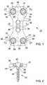
- FIG. 1is a top view of an embodiment of a spinal plating system that may be used for fixation of the human spine.
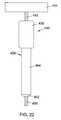
- FIG. 2is a partial cross-sectional view of the spinal plating system taken substantially along line 2 — 2 of FIG. 1 .
- the fasteneris not shown in section.
- FIG. 3is a partial cross-sectional view of the spinal plating system taken substantially along line 3 — 3 of FIG. 1, wherein the fasteners are in a converging orientation within end holes of a plate. The fasteners are not shown in section.
- FIG. 4is a partial cross-sectional view of the spinal plating system taken substantially along line 4 — 4 of FIG. 1, wherein the fasteners are in a diverging orientation within end holes of a plate 5 , the fasteners are not shown in section.
- FIG. 5depicts an embodiment of a fastener with grooves and holes to engage a locking mechanism.
- FIG. 6is a partial front view of a fastener with holes in the fastener head.
- FIG. 7is a top view of a fastener head having grooves for engaging a locking mechanism.
- FIG. 8is a top view of an embodiment of a fastener head with a hexagonal opening and holes to engage a locking mechanism.
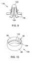
- FIG. 9is a perspective view of a locking mechanism.
- FIG. 10is a perspective view of a ring that may be used with a fastener and a locking mechanism.
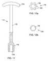
- FIG. 11is a partial sectional view of an insertion/extraction tool for fasteners with locking mechanisms.
- FIG. 12 ais a bottom view of a driver head of the insertion/extraction tool shown in FIG. 11 .
- the toolmay be used with the fastener head shown in FIG. 7 .
- FIG. 12 bis a bottom view of the driver head of the insertion and removal tool shown in FIG. 11 which may be used with the fastener head shown in FIG. 8 .
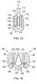
- FIG. 13is a sectional view of a fastener head with an insertion/extraction tool and compressed locking mechanism during an insertion process.
- FIG. 14is a sectional view of a fastener head and locking mechanism inserted into a ring.
- FIG. 15is a perspective view of an embodiment of a fastener.
- FIG. 16is a front view of an embodiment of a fastener head.
- FIG. 17is a perspective view of an embodiment of a fastener.
- FIG. 18is a front view of an embodiment of a fastener head with a groove.
- FIG. 19is a perspective view of an embodiment of a ring.
- FIG. 20is a perspective view of an embodiment of a ring.
- FIG. 21is a perspective view of an embodiment of a ring.
- FIG. 22is front view of an insertion/extraction tool which may be used with the ring of FIG. 21 .
- FIG. 23 ais a partial cross sectional view of a fastener during insertion in the ring of FIG. 21 .
- the shaft of the insertion/extraction toolis not shown in cross section.
- FIG. 23 bis a partial cross sectional view of a fastener after insertion in the ring of FIG. 21 .
- the shaft of the insertion/extraction toolis not shown in cross section;
- FIG. 23 cis a partial cross sectional view of a fastener during removal from the ring of FIG. 21 .
- the shaft of the insertion/extraction toolis not shown in cross section.
- a spinal plating systemis designated generally as 20 .
- the spinal plating system 20may be used to correct problems in the lumbar and cervical portions of the spine.
- the plating system 20may be implanted into the occiput bone that is located at the base of the skull.
- the plating system 20may also be installed anterior to the spine.
- the spinal plating system 20includes plate 22 that is placed adjacent to a portion of the spine and spans at least two vertebrae. Plate 22 may include four end holes 24 , located at corners of the plate. End holes 24 pass vertically through plate 22 such that the holes extend from an upper surface 26 to a lower surface 28 of the plate as depicted in FIG. 2 . End holes 24 are configured to receive rings 30 .
- Fasteners 32fit within the rings 30 .
- “fastener”means any elongated member, threaded or non-threaded, which is securable within a bone.
- Fastenersinclude, but are not limited to screws, nails, rivets, trocars, pins, and barbs.
- the fastenermay be a bone screw.
- Rings 30fixedly attach fastener heads 34 of fasteners 32 to plate 22 .
- Gap 36may exist in each of the rings 30 .
- a gap 36allows for expansion and contraction of a ring 30 . Ring contraction allows a ring 30 to be easily inserted into an end hole 24 of the plate 22 .
- the spinal plating system 20may also include one or more central holes 38 that extend vertically through plate 22 .
- One of the central holes 38may be located at about the mid-point of the plate 22 .
- Head 40 of fastener 42is positioned within one of the central holes 38 .
- Multiple central holes 38provide a surgeon with options as to the most desirable location for placement of a fastener 42 .
- Fastener 42may be used to connect plate 22 to a bone graft (not shown).
- FIG. 2shows a fastener 42 within one of the central holes 38 of plate 22 .
- Fastener 42may include head 40 and shank 44 .
- the shank 44extends from the base of head 40 .
- the inner surface of a central hole 38tapers so that the hole is larger at upper plate surface 26 than at the lower plate surface 28 .
- the outer surface of the fastener head 40has a taper that generally corresponds to the taper of the central hole 38 .
- fastener 42may become locked into place within the central hole 38 once the fastener has been inserted to a desired depth within the bone graft.
- the bone plate 22may have spikes 45 extending from the lower plate surface 28 .
- the plate 22may have a curvature.
- the curvaturemay enhance fixation of the plate 22 to a bone.
- the bone plate 22may have one or more spikes 45 located on the surface of the plate that faces the bone.
- the spikes 45may be disposed in pairs at opposite ends of the plate proximate the end holes 24 .
- the spikes 45may be tapped into the bone to help inhibit the bone plate 22 from slipping during surgical implantation.
- FIG. 3depicts a cross-sectional view of an embodiment of a final plating system 20 wherein a pair of fasteners 32 are in a converging configuration.
- FIG. 4depicts a cross-sectional view of an embodiment of a spinal plating system wherein a pair of fasteners 32 are in a diverging configuration.
- Ring 30fits into a hole 24 between plate 22 and fastener head 34 .
- Inner surfaces 46 of holes 24may have arcuate or spherical contours.
- Outside surfaces 48 of rings 30may have arcuate or spherical contours that substantially correspond to the contours of the inner surfaces 46 of the holes 24 .
- Having a contoured ring outer surface 48 that substantially corresponds to the contour of the inner hole surface 46allows a ring 30 positioned in a hole 24 to be capable of polyaxial rotation within the end hole 24 .
- the combination of ring 30 within end hole 24functions like a ball and socket since the ring may be swiveled or polyaxially rotated within the end hole.
- the ability of the ring 30 to rotate polyaxially within the end hole 24allows a fastener 32 to be positioned through the plate 22 at various angles with respect to an axis that is perpendicular to the plate.
- FIGS. 3 and 4show angle A for particular fastener configurations.
- the angle Ais defined between the longitudinal axis 50 of the fastener 32 and imaginary axis 52 that is perpendicular to the plate 22 .
- the angle Amay range from 0 to about 45 degrees, preferably from about 0 to about 30 degrees, and more preferably from 0 to about 0 and 15 degrees.
- Fasteners 32may also be set in positions such that the fasteners are non-planar with respect to a latitudinal plane extending through plate 22 .
- one fastener 32may be positioned out of the page and another fastener 32 may be positioned into the page, as depicted in FIGS. 3 and 4.
- Fasteners 32 set in diverging or converging directions in the end holes 24may reduce the possibility of backout.
- the use of rings 30 to fixedly attach fasteners 32 to plate 22may inhibit damage to tissue structures by any fasteners that do loosen within a bone, since such fasteners would remain attached to the plate 22 .
- Fasteners 32may be placed in uni-cortical positions within a bone since the problem of fastener backout is reduced by having obliquely angulated fasteners in converging or diverging configurations.
- Ring 30may at least partially surrounds head 34 of fastener 32 positioned within end hole 24 .
- a shank 54 of fastener 32may include threading 56 to allow the fastener to be inserted into a bone when fastener 32 is rotated.
- fastener head 34may include a cavity 58 that extends from the top of the head to an inner portion of the head. Cavity 58 may be shaped to receive an end of a tool that inserts or removes the fastener 32 from a bone.
- the tool endmay be in the form of a hex wrench, a star wrench or a screwdriver blade.
- Inner surface 60 of ring 30 and outer surface 62 of head 34may have mating tapered surfaces, as depicted in FIG. 3 and FIG. 4 .
- the bottom portion of head 34may be smaller than the upper portion of an unstressed ring 30 , while the upper portion of the head may be larger than the upper portion of the ring.
- head 34applies a radial force to ring 30 which causes the ring to expand within the end hole 24 . Expanding the ring 30 increases the size of gap 36 and may cause the outside surface 46 of the ring to abut against inner surface 46 of the end hole 24 .
- Ring 30may be capable of swiveling within a hole 24 so that one portion of ring 30 is adjacent to the upper surface 26 of bone plate 22 while another portion of the ring lies adjacent to the lower surface 28 of the bone plate.
- ring 30may sufficiently thin to reside within end hole 24 without extending beyond the upper or lower surface 26 , 28 of bone plate 22 .
- the ring 30 and fastener head 34remain within end hole 24 so that the spinal plating system 20 may have a minimal profile width. Having rings 30 and the fastener heads 34 which do not extend above the upper surface 26 or below the lower surface 28 of plate 22 may prevent the rings and heads from contacting adjacent tissue structures.
- fasteners 32may be capable of being angulated relative to bone plate 22 such that the rings 30 extend from the end holes 24 beyond upper and/or lower surfaces of the bone plate.
- the spinal plating system 20is prepared for surgical implantation by positioning rings 30 within end holes 24 .
- holesmay be drilled and tapped into the bones to which plate 22 is to be attached.
- Plate 22may then positioned adjacent to the bones and over the holes in the bone.
- Fasteners 32may be placed through a ring 30 and into the bone holes. Each fastener 32 may be obliquely angulated into the plate 22 .
- the fasteners 32may be inserted into the bone until the fastener heads 34 expand the rings 30 against the inner surfaces 46 of the holes 24 ; thus fixing the fasteners to the rings, and the rings to the plate 22 .
- a fastener 42may be positioned in one of the central holes 38 .
- ring 30has an outer width that is less than or about equal to the width of an end hole 24 in bone plate 22 at a location between an upper surface 26 and lower surface 28 of the bone plate.
- the width of each end hole 24 proximate the upper and lower surfaces 26 , 28 of bone plate 22is less than or about equal to an outer width of ring 30 .
- the width of the ringmay inhibit a ring positioned in a hole from falling out of the hole. Prior to surgery, a ring 30 may be positioned within each end hole 24 of bone plate 22 .
- ring 30When seated within hole 24 , ring 30 may be capable of swiveling within the hole, but the ring is inhibited from falling out of the hole because of reduced width of the hole proximate the upper and lower surfaces 26 , 28 of the plate 22 .
- a surgeonmay use a bone plate 22 having rings 30 positioned within holes 24 prior to surgery. Alternatively, rings 30 may be manually positioned within holes 24 during surgery.
- Texturing the outer surface 48 of a ring 30 or an inner surface 46 of a hole 24may further inhibit movement of a fastener 32 with respect to a bone plate 22 . Both surfaces may be textured to more effectively inhibit movement of a fastener 32 with respect to a bone plate 22 .
- the outer surface 48 of ring 30 and the inner surface of end hole 24are formed as relatively smooth surfaces. While the friction between these smooth surfaces tends to be sufficient to maintain fastener 32 in a fixed position with respect to plate 22 ; under stressful conditions ring 30 may rotate within hole 24 .
- the coefficient of friction between hole 24 and ring 30is increased. The increase in friction between hole 24 and ring 30 may help to inhibit fastener movement relative to plate 22 .
- textured surfacesmay be used to increase the coefficient of friction between ring 30 and hole 24 .
- any process that transforms a relatively smooth surface into a textured surface having an increased coefficient of frictionmay be used.
- Methods for forming a textured surfaceinclude, but are not limited to: sanding, forming grooves within a surface, shot peening processes, electric discharge processes, and embedding of hard particles within a surface.
- a shot peening process for forming a textured surfaceis described in U.S. Pat. No. 5,526,664 to Vetter which is incorporated by reference as if set forth herein.
- a shot peening processinvolves propelling a stream of hardened balls, typically made of steel, at a relatively high velocity at a surface. To create a pattern upon an area of the surface the stream is typically moved about the surface. The speed by which the stream is moved about the surface determines the type of textured surface formed.
- An electrical discharge processis based on the principle of removal of portions of a metal surface by spark discharges.
- a sparkis generated between the surface to be treated and an electrode by creating potential differential between the tool and the electrode.
- the spark producedtends to remove a portion of the surface disposed between the electrode and the surface.
- the electrodeis relatively small such that only small portions of the surface are removed.
- By moving the electrode about the surfacenumerous cavities may be formed within the surface. Typically these cavities are somewhat pyramidal in shape.
- Various patternsmay be formed within the surface depending on how the electrode is positioned during the discharge.
- Electric discharge machinesare well known in the art. A method for forming a frictional surface within a metal surface using an electric discharge process is described in U.S. Pat. No. 4,964,641 to Miesch et al., which is incorporated by reference as if set forth herein.
- Embedding hardened particles in a surfaceproduces a textured surface.
- a method for embedding hardened particles in a metal surfaceis described in U.S. Pat. No. 4,768,787 to Shira, which is incorporated by reference as if set forth herein.
- the method of Shirainvolves using a laser or other high-energy source to heat the surface such that the surface melts in selected areas. Just before the molten area re-solidifies, a stream of abrasive particles is directed to the area. In this manner some of the particles tend to become embedded within the molten surface.
- the particlestypically have a number of sharp edges that protrude from the surface after the particles have been embedded within the surface.
- the inner surface 46 of hole 24may be textured using a pattern of grooves.
- the outer surface 48 of ring 30may be textured using an electrical discharge method. When coupled together the textured surfaces of hole 24 and ring 30 may interact with each other to provide additional resistance to movement of the ring within the hole.
- FIG. 5illustrates an embodiment of fastener 100 .
- the fastener 100may include fastener head 102 , opening 104 , optional grooves 106 , holes 108 , shank 110 and threads 112 .
- Opening 104accepts a drive tool, such as drive tool 114 , which is described below.
- the opening 104 , grooves 106 and holes 108accept locking mechanism 116 , as described below.
- Holes 108extend from the outer surface 118 of head 102 to the opening 104 .
- the outer surface 118is substantially cylindrical.
- the head 102tapers from a widest portion near the upper surface of the head to a narrowest portion near the shank 110 .
- FIG. 6is a side view of the head 102 of an embodiment of fastener 100 showing holes 108 and optional rim 120 .
- Rim 120may serve to limit the insertion of fastener 100 into a ring 30 during use.
- FIG. 7is a top view of the head 102 of a fastener 100 with optional grooves 106 .
- FIG. 8shows an alternate embodiment of fastener 100 having a hexagonal shape opening 104 and no grooves.
- FIG. 9illustrates a locking mechanism 116 used with fastener 100 .
- Locking mechanism 116includes top 122 with shafts 124 extending downwards and outwards from the top.
- Prongs 126are located at ends of shafts 124 .
- Prongs 126may be substantially parallel to each other and also may be substantially parallel to the locking mechanism top 122 .
- the shafts 124have a spring-like action which allows the shafts 124 to be compressed. The spring-like action also allows the shafts to return to an original configuration when not compressed.
- FIG. 10illustrates an embodiment of a ring 130 that may be used in combination with fastener 100 and locking mechanism 116 .
- Ring 130includes groove 132 .
- Groove 132engages prongs 126 on locking mechanism 116 to secure fastener 100 in ring 130 after insertion.
- Gap 36 in ring 130allows the ring to contract during insertion of the ring 130 into an end hole 24 of the bone plate 22 .
- Gap 36also allows ring 130 to be expanded by the head 102 of fastener 100 in the ring 130 to abut the ring against the inner surface 46 of the end hole 24 . Abutting the ring 130 against the inner surface 46 of the end hole 24 may fix the position of fastener 32 relative to the bone plate 22 .
- FIG. 11illustrates tool 114 .
- the tool 114may be used during the insertion and extraction of a fastener 100 and locking mechanism 116 .
- the insertion/extraction tool 114includes a shaft 172 .
- One end of shaft 172may include a handle 174 for turning the tool during insertion and removal of a fastener 100 .
- FIG. 11shows a modified T-handle 174 coupled to the shaft 172 , but any type of handle that allows torque to be applied to the fastener during insertion and removal may be used.
- driver head 176At an opposite end of shaft 172 from handle 174 is driver head 176 .
- the outer surface of driver head 176may be shaped to complement the shape of opening 104 in the head of the fastener 100 .
- Driver head 176may be inserted into the opening 104 of the fastener 100 .
- the fastenermay be inserted in an end hole 24 of a bone plate 22 and into a bone by rotating insertion/extraction tool 114 .
- Driver head 176includes cavity 178 .
- the inner surface of the cavitymay slide over and compress the shafts 124 and prongs 126 of a locking mechanism 116 .
- FIG. 12 ashows a bottom view of an embodiment of a driver head 176 of an insertion/extraction tool 114 .
- the driver head of FIG. 12 amay be used with the type of fastener head 102 shown in FIG. 7 .
- the driver head 176has cavity 178 which allows the driver head to slide over and compress a locking mechanism 116 .
- the driver head 176includes ridges 180 for engaging complementary grooves 106 in the opening 104 of a fastener head 102 .
- FIG. 12 bshows an alternate embodiment of a driver head 176 of an insertion/extraction tool 114 .
- the driver head of FIG. 12 bmay be used with the type of fastener head 102 shown in FIG. 8 .
- the driver head 176has cavity 178 which allows the driver head to slide over and compresses a locking mechanism 116 .
- the driver head 176may be hexagonal shaped to mate with opening 104 of a fastener head 102 .
- FIG. 13shows a cross sectional view of an embodiment of a fastener 100 , locking mechanism 116 , and insertion/extraction tool 114 during the insertion process.
- Driver head 176inserts into opening 104 of fastener head 102 .
- Shafts 124 of locking mechanism 116are compressed within cavity 178 of driver head 176 .
- the compression of shafts 124causes prongs 126 to retract in holes 108 , which allow fastener head 102 to be inserted into a ring 130 without interference by extended prongs 126 .
- the shafts 124uncompress, which causes the prongs 126 to extend out of holes 108 .
- FIG. 14shows a cross sectional view of an embodiment of a fastener 100 , locking mechanism 116 , and ring 130 after the fastener has been fully inserted in the ring and the insertion/extraction tool 114 has been removed.
- Shafts 124 of locking mechanism 116are uncompressed, allowing prongs 126 to extend out of holes 108 in fastener head 102 .
- Prongs 126extend into groove 132 on the ring 130 .
- insertion/extraction tool 114is inserted in the opening 104 in fastener head 102 to compress the shafts 124 of the locking mechanism 116 . Compressing the shafts 124 causes the prongs 126 to retract through holes 108 and removes the connection between the prongs and the ring 130 . The tool 114 may then be rotated to remove the fastener 100 from the bone.
- fastener backout from the bone platemay be resisted by the locking mechanism-groove connection between locking mechanism 116 and the ring 130 .
- fastener head 102will tend to remain within ring 130 in the hole 24 of the plate 22 .
- holesmay be drilled and tapped into the bones to which the bone plate 22 is to be attached.
- the bone plate 22may be positioned adjacent to the bones.
- Rings 130may be positioned within each end hole 24 before or during the surgical procedure.
- a fastener 100with a pre-inserted locking mechanism, may be positioned through a ring 130 .
- An insertion/extraction tool 114may be inserted in the opening 104 of threaded fastener 100 to compress the locking mechanism 116 within the cavity of the driver head of the tool. Compressing the locking mechanism 116 retracts the prongs 126 of the locking mechanism within the fastener opening 104 .
- the fastener 100may then be rotated to insert the fastener 100 into a bone.
- fastener head 102moves into the ring 130 . Movement of head 102 into ring 130 causes the ring to expand against the end hole 24 to fix the fastener 100 relative to the plate 22 .
- insertion/extraction tool 114is removed. Removing the tool 114 causes the locking mechanism 116 to uncompress so that the prongs 126 extend through the holes 108 in the fastener head 102 and engage ring the groove 132 in the ring 130 .
- Fasteners 100may be inserted through the remaining end holes 24 and into bone to securely attach the plate 22 to the bones.
- FIG. 15illustrates an embodiment of a fastener 200 with fastener head 202 having groove 204 .
- the groove 204may engage fingers 232 on ring 230 (the ring shown in FIGS. 19 and 20 ) to secure the fastener 200 within the ring 230 .
- Fastener 200may include the head 202 and shank 206 with threading 208 .
- Head 202may include opening 210 configured to accept a driving tool.
- the engagement of a finger 232 of a ring 230 on groove 204may inhibit fastener 200 from backing out of the ring after insertion of the fastener into the plate 22 .
- the outer surface of head 202is substantially cylindrical.
- the head 202may taper. The widest portion of the head 202 may be near the top surface of the head, and the narrowest portion may be near the shank 206 .
- FIG. 17illustrates an embodiment of a fastener 200 which has radial slots 212 extending from the outer surface of the head into the opening 210 .
- the radial slots 212may allow a portion of head 202 to contract during insertion.
- the radial slots 212may also be used to engage a portion of a drive head of an insertion/extraction tool (not shown).
- FIGS. 15, 16 , and 17illustrate fastener heads 202 wherein the grooves 204 are rims along top edges of the heads.
- FIG. 18illustrates an embodiment of a fastener 200 wherein the groove 204 is located at a position along the side of the fastener head 202 .
- the groove 204may be located at any position along the side of the fastener head 202 .
- FIGS. 19 and 20show perspective views of embodiments of ring 230 that may be used with fasteners having a groove.
- Ring 230may include bottom 234 , top 238 , an outer surface 48 , an inner surface 60 , gap 36 , and slots 240 and notches 242 .
- the slots 240 and notches 240may form the fingers 232 .
- Gap 36may allow ring 230 to contract. Contraction of the ring 230 may facilitate the insertion of the ring into an end hole 24 in a bone plate 22 .
- Gap 36may also allow the ring 230 to expand against the end hole 24 when a fastener head 202 passes into the ring. Expansion of the ring against the hole 24 fixes the fastener 200 relative to the bone plate 22 .
- outer surface 48 of the ring 230may be textured to increase the coefficient of friction between ring 230 and the hole 24 .
- inner surface 60 of the ring 230may be tapered to match a tapered head of a fastener 200 . Having tapered surfaces may facilitate the expansion of ring in an end hole 24 during insertion of the fastener into the bone plate system 20 .
- the shape of the end hole 24may push the fingers 232 inwards past the edge of the groove 204 of a fastener 200 when the groove is inserted into a ring 230 so that the groove passes an upper edge of the ring slots 240 .
- the inward positioned fingers 232may inhibit fastener 200 from backing out of the ring 230 and the hole 24 .
- the fastener head 202may expand the outside surface 48 of the ring against the inner surface 46 of the end hole 24 to fix the fastener 200 to the ring 230 , and the ring to the plate 22 .
- FIG. 21is a perspective view of an embodiment of a ring that may be used with fasteners 200 that have rims 204 , such as the fasteners shown in FIGS. 15-17.
- Ring 430may include bottom 432 , top 434 , outer surface 48 , inner surface 60 , gap 36 , notches 436 , and ridges 438 .
- Notches 436divide the ring 430 into segments or paddles 440 .
- Notches 436 and gap 36may allow ring 430 to contract, facilitating the insertion of the ring into a hole 24 of a bone plate 22 .
- Notches 436 and gap 36may also allow ring 430 to expand when a fastener head 202 passes into the ring to fix the position of the fastener relative to the bone plate 22 .
- Notches 436may also allow paddles 436 to bend outwards during insertion of a fastener 200 .
- the outer surface 48 and/or the inner surface 60may be textured.
- the inner surface of the ring 430may be tapered to correspond to the taper of a fastener head 202 .
- FIG. 22illustrates an embodiment of an insertion tool/extraction tool 450 for use with a fastener 200 and ring 430 .
- Insertion/extraction tool 450may include shaft 452 , handle 454 , driver head 456 , and extraction member 458 .
- handle 454At one end of shaft 452 is handle 454 for turning the tool during insertion and removal of a fastener 200 .
- the illustrationshows a T-handle, but any other type of handle that allows sufficient torque to be applied to the fastener 200 to allow for insertion or removal of the fastener may be used.
- driver head 456At the opposite end of shaft 452 from handle 454 .
- the outer surface of driver head 456may be shaped complementary to the shape of the opening 210 in the head 202 of the fastener 200 .
- the extraction member 458 shown in FIG. 22may include grip 459 , passage 460 , (shown in FIG. 23 c ), tip 462 , and extraction head 464 .
- the passage 460extends through the grip 459 and the extraction head 464 .
- extraction member 458may be removed from shaft 452 .
- extraction member 458may be slid back on to shaft 452 .
- Driver head 456is inserted into the opening 210 of the fastener 200 .
- Extraction member 458slides down shaft 452 until tip 462 of extraction head 464 contacts the top of the ring 430 .
- FIG. 23 a, 23 b, and 23 cshow partial cross sectional views of a threaded fastener 200 , ring 430 , and insertion/extraction tool 450 during the insertion and extraction processes.
- driver head 456 of insertion/extraction tool 450is inserted in opening 210 of fastener head 202 .
- Ring 430is positioned inside a hole 24 in a bone plate and the bone plate is positioned on a bone (bone and bone plate not shown).
- Fastener 200is screwed into the bone until the outer surface of fastener head 202 contacts the surfaces of the paddles 440 .
- the tapering of the outer surface of fastener head 202provides a ramping force on the surfaces of the paddles 440 , to bend the paddles outwards as fastener 200 is screwed farther into the bone.
- fastener 200has been screwed in to the desired depth.
- Fastener head 202penetrates ring 430 far enough to allow ridges 438 to snap onto rim 204 on fastener head 202 .
- Driver head 456 of insertion/extraction tool 450is shown still inserted in opening 210 prior to removal from the opening. After insertion, if the fastener 200 becomes loose within the bone, fastener backout from the bone plate may be resisted by the ridge-rim connection between fastener head 202 and ring 430 .
- the fastener head 202will tend to remain within ring 430 in the hole 24 of the plate 22 so as not to protrude from the plate into surrounding body tissue.
- the freedom of movementis limited so that the fastener head 202 may not protrude from the plate 22 .
- FIG. 23 cshows insertion/extraction tool 250 being used to remove a fastener 200 .
- Driver head 256is inserted in opening 210 of fastener 200 .
- Extraction head 464is slid down shaft 452 of insertion/extraction tool 450 until the sloped surface of tip 462 applies a wedging force against the sloped upper surfaces of paddles 440 . The wedging force bends the paddles 440 outwards to disengage the ridges 438 from the rim 204 .
- Fastener 200may then be backed out of the bone, the ring 430 and the plate 22 .
- the plate, fasteners, and locking mechanismsmay be made of steel (e.g, stainless steel), titanium, steel alloys or titanium alloys. These materials are generally nontoxic, bio-compatible, strong, and non-corrosive. Other materials that have these properties may also be used.
- the plate and the ringsmay be made of a number of bio-compatible materials including metals, plastics, and composites.
Landscapes
- Health & Medical Sciences (AREA)
- Orthopedic Medicine & Surgery (AREA)
- Surgery (AREA)
- Life Sciences & Earth Sciences (AREA)
- Heart & Thoracic Surgery (AREA)
- Nuclear Medicine, Radiotherapy & Molecular Imaging (AREA)
- Engineering & Computer Science (AREA)
- Biomedical Technology (AREA)
- Medical Informatics (AREA)
- Molecular Biology (AREA)
- Animal Behavior & Ethology (AREA)
- General Health & Medical Sciences (AREA)
- Public Health (AREA)
- Veterinary Medicine (AREA)
- Neurology (AREA)
- Surgical Instruments (AREA)
Abstract
Description
Claims (130)
Priority Applications (10)
| Application Number | Priority Date | Filing Date | Title |
|---|---|---|---|
| US09/479,458US6331179B1 (en) | 2000-01-06 | 2000-01-06 | System and method for stabilizing the human spine with a bone plate |
| PCT/US2001/000724WO2001049191A1 (en) | 2000-01-06 | 2001-01-08 | System and method for stabilizing the human spine with a bone plate |
| EP01901919AEP1259176B1 (en) | 2000-01-06 | 2001-01-08 | Bone plate system for bone stabilization |
| AU27770/01AAU2777001A (en) | 2000-01-06 | 2001-01-08 | System and method for stabilizing the human spine with a bone plate |
| CA002396535ACA2396535C (en) | 2000-01-06 | 2001-01-08 | System and method for stabilizing the human spine with a bone plate |
| JP2001549560AJP4741141B2 (en) | 2000-01-06 | 2001-01-08 | System and method for stabilizing a human spine with a bone plate |
| US10/015,206US6964664B2 (en) | 2000-01-06 | 2001-11-19 | System and method for stabilizing the human spine with a bone plate |
| US10/735,976US7611527B2 (en) | 2000-01-06 | 2003-12-15 | System and method for stabilizing the human spine with a bone plate |
| US12/575,639US8025677B2 (en) | 2000-01-06 | 2009-10-08 | System and method for stabilizing the human spine with a bone plate |
| US13/225,753US20120016365A1 (en) | 2000-01-06 | 2011-09-06 | Bone plate system and method for spine stabilization |
Applications Claiming Priority (1)
| Application Number | Priority Date | Filing Date | Title |
|---|---|---|---|
| US09/479,458US6331179B1 (en) | 2000-01-06 | 2000-01-06 | System and method for stabilizing the human spine with a bone plate |
Related Child Applications (1)
| Application Number | Title | Priority Date | Filing Date |
|---|---|---|---|
| US10/015,206ContinuationUS6964664B2 (en) | 2000-01-06 | 2001-11-19 | System and method for stabilizing the human spine with a bone plate |
Publications (1)
| Publication Number | Publication Date |
|---|---|
| US6331179B1true US6331179B1 (en) | 2001-12-18 |
Family
ID=23904085
Family Applications (5)
| Application Number | Title | Priority Date | Filing Date |
|---|---|---|---|
| US09/479,458Expired - LifetimeUS6331179B1 (en) | 2000-01-06 | 2000-01-06 | System and method for stabilizing the human spine with a bone plate |
| US10/015,206Expired - LifetimeUS6964664B2 (en) | 2000-01-06 | 2001-11-19 | System and method for stabilizing the human spine with a bone plate |
| US10/735,976Expired - Fee RelatedUS7611527B2 (en) | 2000-01-06 | 2003-12-15 | System and method for stabilizing the human spine with a bone plate |
| US12/575,639Expired - Fee RelatedUS8025677B2 (en) | 2000-01-06 | 2009-10-08 | System and method for stabilizing the human spine with a bone plate |
| US13/225,753AbandonedUS20120016365A1 (en) | 2000-01-06 | 2011-09-06 | Bone plate system and method for spine stabilization |
Family Applications After (4)
| Application Number | Title | Priority Date | Filing Date |
|---|---|---|---|
| US10/015,206Expired - LifetimeUS6964664B2 (en) | 2000-01-06 | 2001-11-19 | System and method for stabilizing the human spine with a bone plate |
| US10/735,976Expired - Fee RelatedUS7611527B2 (en) | 2000-01-06 | 2003-12-15 | System and method for stabilizing the human spine with a bone plate |
| US12/575,639Expired - Fee RelatedUS8025677B2 (en) | 2000-01-06 | 2009-10-08 | System and method for stabilizing the human spine with a bone plate |
| US13/225,753AbandonedUS20120016365A1 (en) | 2000-01-06 | 2011-09-06 | Bone plate system and method for spine stabilization |
Country Status (6)
| Country | Link |
|---|---|
| US (5) | US6331179B1 (en) |
| EP (1) | EP1259176B1 (en) |
| JP (1) | JP4741141B2 (en) |
| AU (1) | AU2777001A (en) |
| CA (1) | CA2396535C (en) |
| WO (1) | WO2001049191A1 (en) |
Cited By (350)
| Publication number | Priority date | Publication date | Assignee | Title |
|---|---|---|---|---|
| US20020055743A1 (en)* | 2000-08-24 | 2002-05-09 | Michael Seemann | Condylus screw |
| US20020099386A1 (en)* | 2001-01-19 | 2002-07-25 | Aesculap Ag & Co. Kg | Locking mechanism for a bone screw |
| US20020133154A1 (en)* | 2001-03-15 | 2002-09-19 | Saint Martin Pierre Henri | Anchoring member with safety ring |
| US20030073997A1 (en)* | 2001-10-17 | 2003-04-17 | Doubler Robert L. | Split ring bone screw for a spinal fixation system |
| US20030093082A1 (en)* | 2000-06-26 | 2003-05-15 | Stryker Spine | Bone screw retaining system |
| US6585738B1 (en)* | 1998-07-06 | 2003-07-01 | Stryker Spine | Spinal osteosynthesis device for anterior fixation with plate |
| US20030135213A1 (en)* | 2001-04-06 | 2003-07-17 | Lehuec Jean-Charles | Anterior planting system and method |
| US6599290B2 (en) | 2001-04-17 | 2003-07-29 | Ebi, L.P. | Anterior cervical plating system and associated method |
| US6605090B1 (en)* | 2000-10-25 | 2003-08-12 | Sdgi Holdings, Inc. | Non-metallic implant devices and intra-operative methods for assembly and fixation |
| US6626909B2 (en) | 2002-02-27 | 2003-09-30 | Kingsley Richard Chin | Apparatus and method for spine fixation |
| US6679883B2 (en) | 2001-10-31 | 2004-01-20 | Ortho Development Corporation | Cervical plate for stabilizing the human spine |
| US20040015169A1 (en)* | 2002-07-16 | 2004-01-22 | Larry Gause | Bone plate fastener retaining mechanisms and methods |
| US20040019353A1 (en)* | 2002-02-01 | 2004-01-29 | Freid James M. | Spinal plate system for stabilizing a portion of a spine |
| US20040034352A1 (en)* | 2002-08-16 | 2004-02-19 | Needham Dusty Anna | Systems, instrumentation and techniques for retaining fasteners relative to a bone plate |
| US20040034356A1 (en)* | 2002-07-16 | 2004-02-19 | Lehuec Jean-Charles | Plating system for stabilizing a bony segment |
| US6730093B2 (en)* | 2001-03-15 | 2004-05-04 | Stryker Spine | Anchoring member with packer |
| EP1415605A1 (en)* | 2002-11-04 | 2004-05-06 | Centerpulse Orthopedics Ltd. | Bone fixation system |
| WO2004041100A1 (en)* | 2002-10-30 | 2004-05-21 | Spinal Concepts, Inc. | Spinal stabilization system insertion and methods |
| US6740088B1 (en) | 2000-10-25 | 2004-05-25 | Sdgi Holdings, Inc. | Anterior lumbar plate and method |
| US20040127904A1 (en)* | 2002-12-31 | 2004-07-01 | Konieczynski David D. | Bone plate and resilient screw system allowing bi-directional assembly |
| US20040133207A1 (en)* | 2002-10-11 | 2004-07-08 | Abdou M. Samy | Distraction screw for skeletal surgery and method of use |
| US20040133278A1 (en)* | 2002-10-31 | 2004-07-08 | Marino James F. | Spinal disc implant |
| US20040147928A1 (en)* | 2002-10-30 | 2004-07-29 | Landry Michael E. | Spinal stabilization system using flexible members |
| US20040204716A1 (en)* | 2003-04-09 | 2004-10-14 | Jonathan Fanger | Drill guide with alignment feature |
| US20040204713A1 (en)* | 2003-01-10 | 2004-10-14 | Abdou M. Samy | Plating system for bone fixation and subsidence and method of implantation |
| US20040210217A1 (en)* | 2003-04-21 | 2004-10-21 | Baynham Bret O'neil | Bone fixation plate |
| US20040225290A1 (en)* | 2001-03-27 | 2004-11-11 | Nuvasive, Inc. | Hinged anterior thoracic/lumbar plate |
| US20040260291A1 (en)* | 2003-06-20 | 2004-12-23 | Jensen David G. | Bone plates with intraoperatively tapped apertures |
| FR2856272A1 (en)* | 2003-06-17 | 2004-12-24 | Scient X | ANTI-EXTRACTION DEVICE OF AN ANCHORING SCREW FOR AN OSTEOSYNTHESIS ELEMENT |
| US20050010217A1 (en)* | 2003-07-07 | 2005-01-13 | Dalton Brian E. | Spinal stabilization implant and method of application |
| US20050010219A1 (en)* | 2003-07-07 | 2005-01-13 | Dalton Brain E. | Bone fixation assembly and method of securement |
| US20050015089A1 (en)* | 2003-03-26 | 2005-01-20 | Young Robert Allan | Locking bone plate |
| WO2004071276A3 (en)* | 2003-02-05 | 2005-02-17 | Pioneer Lab Inc | Bone plate system |
| US20050043736A1 (en)* | 2001-12-24 | 2005-02-24 | Claude Mathieu | Device for osteosynthesis |
| US20050075633A1 (en)* | 2003-10-02 | 2005-04-07 | Thomas Ross | Anterior cervical plate |
| US20050090826A1 (en)* | 2003-01-23 | 2005-04-28 | Waldemar Link (Gmbh & Co.) | Medical implant with a secured bone screw |
| US6887241B1 (en)* | 2000-10-06 | 2005-05-03 | Spinal Concepts, Inc. | Adjustable transverse connector with cam activated engagers |
| US20050101958A1 (en)* | 2002-11-04 | 2005-05-12 | Michael Adam | Bone fixing system |
| US20050124994A1 (en)* | 2001-02-21 | 2005-06-09 | Synthes (Usa) | Occipital plate and system for spinal stabilization |
| US20050154389A1 (en)* | 2003-12-16 | 2005-07-14 | Depuy Spine, Inc. | Methods and devices for minimally invasive spinal fixation element placement |
| US20050177163A1 (en)* | 2003-12-29 | 2005-08-11 | Abdou M. S. | Plating system for bone fixation and method of implantation |
| US20050192580A1 (en)* | 2004-02-26 | 2005-09-01 | Dalton Brian E. | Polyaxial locking screw plate assembly |
| US20050240184A1 (en)* | 2002-01-08 | 2005-10-27 | Osman Said G | Method for postoperatively compressing a bone graft |
| US6964664B2 (en)* | 2000-01-06 | 2005-11-15 | Spinal Concepts Inc. | System and method for stabilizing the human spine with a bone plate |
| US20050277940A1 (en)* | 2004-06-15 | 2005-12-15 | Neff James R | Dynamic compression device and driving tool |
| US20050277927A1 (en)* | 2004-06-14 | 2005-12-15 | Guenther Kevin V | Fastening system for spinal stabilization system |
| US20050283152A1 (en)* | 2004-06-17 | 2005-12-22 | Lindemann Gary S | Method and apparatus for retaining screws in a plate |
| US20050288669A1 (en)* | 2004-06-14 | 2005-12-29 | Abdou M S | Occipito fixation system and method of use |
| US20060024213A1 (en)* | 2004-07-28 | 2006-02-02 | Dainippon Screen Mfg. Co., Ltd. | Substrate treating apparatus |
| US20060030859A1 (en)* | 2004-07-20 | 2006-02-09 | Yechiel Gotfried | Targeting apparatus for bone fixation device |
| US20060036250A1 (en)* | 2004-08-12 | 2006-02-16 | Lange Eric C | Antero-lateral plating systems for spinal stabilization |
| US20060036252A1 (en)* | 2004-08-12 | 2006-02-16 | Baynham Bret O | Polyaxial screw |
| US7001389B1 (en)* | 2002-07-05 | 2006-02-21 | Navarro Richard R | Fixed and variable locking fixation assembly |
| US20060069391A1 (en)* | 2004-02-27 | 2006-03-30 | Jackson Roger P | Spinal fixation tool attachment structure |
| US20060074418A1 (en)* | 2004-09-24 | 2006-04-06 | Jackson Roger P | Spinal fixation tool set and method for rod reduction and fastener insertion |
| WO2005023089A3 (en)* | 2003-09-03 | 2006-05-11 | Lan Anh Duong | Bone plate with captive clips |
| US20060111713A1 (en)* | 2004-11-23 | 2006-05-25 | Jackson Roger P | Spinal fixation tool set and method |
| US20060122604A1 (en)* | 2004-12-08 | 2006-06-08 | Depuy Spine, Inc. | Locking bone screw and spinal plate system |
| US20060122602A1 (en)* | 2004-12-08 | 2006-06-08 | Depuy Spine, Inc. | Hybrid spinal plates |
| US20060149264A1 (en)* | 2004-12-20 | 2006-07-06 | Castaneda Javier E | Screw locking systems for bone plates |
| US20060149256A1 (en)* | 1997-08-04 | 2006-07-06 | Wagner Erik J | System and method for stabilizing the human spine with a bone plate |
| US20060155285A1 (en)* | 2005-01-12 | 2006-07-13 | Kent Anderson | Anchor retaining mechanisms for bone plates |
| US7090676B2 (en) | 2002-11-19 | 2006-08-15 | Acumed Llc | Adjustable bone plates |
| US20060195089A1 (en)* | 2005-02-03 | 2006-08-31 | Lehuec Jean-Charles | Spinal plating and intervertebral support systems and methods |
| US20060200134A1 (en)* | 2002-02-01 | 2006-09-07 | James Freid | Spinal plate system for stabilizing a portion of a spine |
| US20060229615A1 (en)* | 2005-02-18 | 2006-10-12 | Abdou M S | Devices and methods for dynamic fixation of skeletal structure |
| US20060235399A1 (en)* | 2005-04-14 | 2006-10-19 | Sdgi Holdings, Inc. | Anti-backout mechanism for an implant fastener |
| US20060241615A1 (en)* | 2005-04-19 | 2006-10-26 | Sdgi Holdings, Inc. | Antero-lateral plating systems and methods for spinal stabilization |
| US20060247639A1 (en)* | 2005-04-29 | 2006-11-02 | Sdgi Holdings, Inc. | Apparatus for retaining a bone anchor in a bone plate and method for use thereof |
| US20060264946A1 (en)* | 2003-03-26 | 2006-11-23 | Young Robert A | Locking bone plate |
| US20060271052A1 (en)* | 2005-05-12 | 2006-11-30 | Stern Joseph D | Revisable anterior cervical plating system |
| US7153309B2 (en) | 2002-11-19 | 2006-12-26 | Acumed Llc | Guide system for bone-repair devices |
| US20060293669A1 (en)* | 2005-06-10 | 2006-12-28 | Sdgi Holdings, Inc. | System and method for retaining screws relative to a vertebral plate |
| US20060293668A1 (en)* | 2005-06-10 | 2006-12-28 | Sdgi Holdings, Inc. | Bone screw locking mechanism and method of use |
| US20060293670A1 (en)* | 2005-06-03 | 2006-12-28 | Smisson Hugh F Iii | Surgical stabilization system |
| US20070010822A1 (en)* | 2005-07-08 | 2007-01-11 | Edward Zalenski | Bone removal tool |
| US20070016206A1 (en)* | 2002-06-24 | 2007-01-18 | Lanx, Llc | Cervical plate |
| US20070032162A1 (en)* | 2004-11-23 | 2007-02-08 | Jackson Roger P | Spinal fixation tool set and method |
| US7175624B2 (en) | 2002-12-31 | 2007-02-13 | Depuy Spine, Inc. | Bone plate and screw system allowing bi-directional assembly |
| US7179261B2 (en) | 2003-12-16 | 2007-02-20 | Depuy Spine, Inc. | Percutaneous access devices and bone anchor assemblies |
| US7189237B2 (en) | 2002-11-19 | 2007-03-13 | Acumed Llc | Deformable bone plates |
| US20070083199A1 (en)* | 2003-09-04 | 2007-04-12 | Abbott Spine | Spinal implant |
| US7204837B2 (en) | 2001-12-14 | 2007-04-17 | Paul Kamaljit S | Spinal plate assembly |
| US20070090238A1 (en)* | 2005-10-20 | 2007-04-26 | Sdgi Holdings, Inc. | Bottom loading multi-axial screw assembly |
| US20070106383A1 (en)* | 2005-10-03 | 2007-05-10 | Abdou M S | Devices and methods for inter-vertebral orthopedic device placement |
| US20070106388A1 (en)* | 2000-07-10 | 2007-05-10 | Sdgi Holdings, Inc. | Flanged interbody spinal fusion implants |
| US20070112427A1 (en)* | 2005-11-16 | 2007-05-17 | Aoi Medical, Inc. | Intervertebral Spacer |
| US20070123884A1 (en)* | 2005-11-09 | 2007-05-31 | Abdou M S | Bone fixation systems and methods of implantation |
| US20070162016A1 (en)* | 2005-10-25 | 2007-07-12 | Matityahu Amir M | Bone fastening assembly and bushing and screw for use therewith |
| US20070162013A1 (en)* | 2005-12-09 | 2007-07-12 | Depuy Spine, Inc. | Spinal plate and drill guide |
| US20070173843A1 (en)* | 2005-12-22 | 2007-07-26 | Matityahu Amir M | Drug delivering bone plate and method and targeting device for use therewith |
| US7255699B2 (en) | 2001-12-14 | 2007-08-14 | Paul Kamaljit S | Spinal plate assembly |
| US20070212915A1 (en)* | 2006-03-07 | 2007-09-13 | Strnad Lee A | Variable axis locking mechanism for use in orthopedic implants |
| US20070233097A1 (en)* | 2003-12-16 | 2007-10-04 | Depuy Spine, Inc. | Methods and devices for spinal fixation element placement |
| US7278997B1 (en) | 2003-03-07 | 2007-10-09 | Theken Spine, Llc | Instrument guide and implant holder |
| US20070270859A1 (en)* | 2006-04-28 | 2007-11-22 | Sdgi Holdings, Inc. | Orthopedic screw with break away drive |
| US7303564B2 (en) | 2002-02-01 | 2007-12-04 | Spinal Concepts, Inc. | Spinal plate extender system and method |
| US7309340B2 (en) | 2003-06-20 | 2007-12-18 | Medicinelodge, Inc. | Method and apparatus for bone plating |
| US20080033448A1 (en)* | 2006-08-04 | 2008-02-07 | Robinson James C | Bone screw removal system |
| US20080045960A1 (en)* | 2004-03-25 | 2008-02-21 | Bruecker Kenneth | Locking tpo plate and method of use |
| US20080051786A1 (en)* | 2006-04-03 | 2008-02-28 | Acumed Llc | Bone plates with hybrid apertures |
| US20080058813A1 (en)* | 2003-07-08 | 2008-03-06 | Yechiel Gotfried | Apparatus and method fixing a fractured bone |
| US7341591B2 (en) | 2003-01-30 | 2008-03-11 | Depuy Spine, Inc. | Anterior buttress staple |
| US20080082102A1 (en)* | 2003-03-26 | 2008-04-03 | Bruecker Kenneth | Locking tpo plate and method of use |
| US20080086131A1 (en)* | 2006-10-06 | 2008-04-10 | Depuy Spine, Inc. | Bone screw fixation |
| US20080097442A1 (en)* | 2006-06-29 | 2008-04-24 | Dixon Robert A | Method and device for improving the function of taper locks used for spinal stabilization |
| US20080119856A1 (en)* | 2006-11-20 | 2008-05-22 | Yechiel Gotfried | Intramedullary nail system and method for fixation of a fractured bone |
| US20080119895A1 (en)* | 2006-11-20 | 2008-05-22 | Thierry Manceau | Locking bone plate with bushing anti-rotation feature |
| US20080140136A1 (en)* | 2003-06-18 | 2008-06-12 | Jackson Roger P | Polyaxial bone screw with cam capture |
| US20080140109A1 (en)* | 2005-12-09 | 2008-06-12 | Park Kee B | Surgical implant |
| US20080188852A1 (en)* | 2007-02-05 | 2008-08-07 | Matityahu Amir M | Apparatus for Repositioning Portions of Fractured Bone and Method of Using Same |
| US20080195098A1 (en)* | 2007-02-09 | 2008-08-14 | Yechiel Gotfried | Intramedullary nail system and method for fixation of a fractured bone |
| US20080195099A1 (en)* | 2007-02-13 | 2008-08-14 | The Brigham And Women's Hospital, Inc. | Osteotomy system |
| US7416553B2 (en) | 2003-04-09 | 2008-08-26 | Depuy Acromed, Inc. | Drill guide and plate inserter |
| US20080208259A1 (en)* | 2006-12-19 | 2008-08-28 | Small Bone Innovations, Inc. | Locking fixation system and lag tool |
| US20080221681A1 (en)* | 2007-03-09 | 2008-09-11 | Warsaw Orthopedic, Inc. | Methods for Improving Fatigue Performance of Implants With Osteointegrating Coatings |
| US20080221688A1 (en)* | 2007-03-09 | 2008-09-11 | Warsaw Orthopedic, Inc. | Method of Maintaining Fatigue Performance In A Bone-Engaging Implant |
| US20080249575A1 (en)* | 2007-04-03 | 2008-10-09 | Warsaw Orthopedic, Inc. | Anchor Member Locking Features |
| US20080249625A1 (en)* | 2007-04-03 | 2008-10-09 | Warsaw Orthopedic, Inc. | Composite Interbody Spacer |
| US20080249569A1 (en)* | 2007-04-03 | 2008-10-09 | Warsaw Orthopedic, Inc. | Implant Face Plates |
| US20080269809A1 (en)* | 2007-03-26 | 2008-10-30 | Laszlo Garamszegi | Bottom-loading pedicle screw assembly |
| US20080288001A1 (en)* | 2007-05-18 | 2008-11-20 | Trace Cawley | Cervical plate locking mechanism and associated surgical method |
| US20080288000A1 (en)* | 2007-05-18 | 2008-11-20 | U.S. Spinal Technologies, L.L.C. | Cervical plate locking mechanism and associated surgical method |
| US20080300634A1 (en)* | 2007-05-31 | 2008-12-04 | Wayne Gray | Spinal interbody system and method |
| US7485132B1 (en) | 2000-10-06 | 2009-02-03 | Abbott Spine Inc. | Transverse connector with cam activated engagers |
| US20090105758A1 (en)* | 2007-10-22 | 2009-04-23 | Gimbel Jonathan A | Dampener system for a posterior stabilization system with a variable length elongated member |
| US7527640B2 (en)* | 2004-12-22 | 2009-05-05 | Ebi, Llc | Bone fixation system |
| US7537604B2 (en) | 2002-11-19 | 2009-05-26 | Acumed Llc | Bone plates with slots |
| US7537603B2 (en) | 2002-07-22 | 2009-05-26 | Acumed Llc | Bone fusion system |
| US7547318B2 (en) | 2004-03-19 | 2009-06-16 | Depuy Spine, Inc. | Spinal fixation element and methods |
| US20090171396A1 (en)* | 2003-04-21 | 2009-07-02 | Baynham Matthew G | Bone fixation plate |
| US7578825B2 (en) | 2004-04-19 | 2009-08-25 | Acumed Llc | Placement of fasteners into bone |
| US20090248087A1 (en)* | 2008-03-03 | 2009-10-01 | Orthohelix Surgical Designs, Inc. | Variable axis locking mechanism for use in orthopedic implants |
| US20090270927A1 (en)* | 2008-04-25 | 2009-10-29 | Pioneer Surgical Technology, Inc. | Bone Plate System |
| US20090281576A1 (en)* | 2008-05-08 | 2009-11-12 | Aesculap Implant Systems, Inc. | Minimally invasive spinal stabilization system |
| US20090299414A1 (en)* | 2003-04-09 | 2009-12-03 | Jackson Roger P | Polyaxial bone screw with uploaded threaded shank and method of assembly and use |
| US7635365B2 (en) | 2003-08-28 | 2009-12-22 | Ellis Thomas J | Bone plates |
| US7662175B2 (en) | 2003-06-18 | 2010-02-16 | Jackson Roger P | Upload shank swivel head bone screw spinal implant |
| US7666185B2 (en) | 2003-09-03 | 2010-02-23 | Synthes Usa, Llc | Translatable carriage fixation system |
| US20100069969A1 (en)* | 2008-09-15 | 2010-03-18 | Ampuero Eduardo A | Low Profile Screw and Washer System for Bone Plating |
| US7708778B2 (en) | 2003-08-05 | 2010-05-04 | Flexuspine, Inc. | Expandable articulating intervertebral implant with cam |
| US20100121327A1 (en)* | 2008-11-11 | 2010-05-13 | Zimmer, Gmbh | Orthopedic screw |
| US7717945B2 (en) | 2002-07-22 | 2010-05-18 | Acumed Llc | Orthopedic systems |
| US7736380B2 (en) | 2004-12-21 | 2010-06-15 | Rhausler, Inc. | Cervical plate system |
| US7740649B2 (en) | 2004-02-26 | 2010-06-22 | Pioneer Surgical Technology, Inc. | Bone plate system and methods |
| US7766915B2 (en) | 2004-02-27 | 2010-08-03 | Jackson Roger P | Dynamic fixation assemblies with inner core and outer coil-like member |
| US20100204798A1 (en)* | 2005-10-21 | 2010-08-12 | Stryker Spine | System and method for fusion cage implantation |
| US7776047B2 (en) | 2003-04-09 | 2010-08-17 | Depuy Spine, Inc. | Guide for spinal tools, implants, and devices |
| US7780706B2 (en) | 2005-04-27 | 2010-08-24 | Trinity Orthopedics, Llc | Mono-planar pedicle screw method, system and kit |
| US7785351B2 (en) | 2003-08-05 | 2010-08-31 | Flexuspine, Inc. | Artificial functional spinal implant unit system and method for use |
| US20100241174A1 (en)* | 2007-10-16 | 2010-09-23 | Robinson James C | Bone screw retaining and removal system |
| US20100268283A1 (en)* | 2000-02-01 | 2010-10-21 | Orbay Jorge L | Volar Fixation System And Methods of Using The Same |
| US7854752B2 (en) | 2004-08-09 | 2010-12-21 | Theken Spine, Llc | System and method for dynamic skeletal stabilization |
| US7862587B2 (en) | 2004-02-27 | 2011-01-04 | Jackson Roger P | Dynamic stabilization assemblies, tool set and method |
| US20110015682A1 (en)* | 2009-07-15 | 2011-01-20 | Orthohelix Surgical Designs, Inc. | Variable axis locking mechanism for use in orthopedic implants |
| US7875065B2 (en) | 2004-11-23 | 2011-01-25 | Jackson Roger P | Polyaxial bone screw with multi-part shank retainer and pressure insert |
| US7887595B1 (en) | 2005-12-05 | 2011-02-15 | Nuvasive, Inc. | Methods and apparatus for spinal fusion |
| US20110054543A1 (en)* | 2009-08-31 | 2011-03-03 | Warsaw Orthopedic, Inc. | Locking mechanism |
| US7901437B2 (en) | 2007-01-26 | 2011-03-08 | Jackson Roger P | Dynamic stabilization member with molded connection |
| US7909869B2 (en) | 2003-08-05 | 2011-03-22 | Flexuspine, Inc. | Artificial spinal unit assemblies |
| US7909848B2 (en) | 2003-06-27 | 2011-03-22 | Depuy Spine, Inc. | Tissue retractor and guide device |
| US7909860B2 (en) | 2003-09-03 | 2011-03-22 | Synthes Usa, Llc | Bone plate with captive clips |
| US7909829B2 (en) | 2003-06-27 | 2011-03-22 | Depuy Spine, Inc. | Tissue retractor and drill guide |
| US7914561B2 (en) | 2002-12-31 | 2011-03-29 | Depuy Spine, Inc. | Resilient bone plate and screw system allowing bi-directional assembly |
| US7918858B2 (en) | 2006-09-26 | 2011-04-05 | Depuy Spine, Inc. | Minimally invasive bone anchor extensions |
| US20110082506A1 (en)* | 2009-10-02 | 2011-04-07 | Spinefrontier, Inc | Cervical plate assembly |
| US20110106157A1 (en)* | 2009-10-30 | 2011-05-05 | Warsaw Orthropedic, Inc. | Self-Locking Interference Bone Screw for use with Spinal Implant |
| US7942909B2 (en) | 2009-08-13 | 2011-05-17 | Ortho Innovations, Llc | Thread-thru polyaxial pedicle screw system |
| US7942910B2 (en) | 2007-05-16 | 2011-05-17 | Ortho Innovations, Llc | Polyaxial bone screw |
| US7942911B2 (en) | 2007-05-16 | 2011-05-17 | Ortho Innovations, Llc | Polyaxial bone screw |
| US7942913B2 (en) | 2004-04-08 | 2011-05-17 | Ebi, Llc | Bone fixation device |
| US7947065B2 (en) | 2008-11-14 | 2011-05-24 | Ortho Innovations, Llc | Locking polyaxial ball and socket fastener |
| US7951173B2 (en) | 2007-05-16 | 2011-05-31 | Ortho Innovations, Llc | Pedicle screw implant system |
| US7951170B2 (en) | 2007-05-31 | 2011-05-31 | Jackson Roger P | Dynamic stabilization connecting member with pre-tensioned solid core |
| US7955364B2 (en) | 2005-09-21 | 2011-06-07 | Ebi, Llc | Variable angle bone fixation assembly |
| US7959677B2 (en) | 2007-01-19 | 2011-06-14 | Flexuspine, Inc. | Artificial functional spinal unit system and method for use |
| US7967850B2 (en) | 2003-06-18 | 2011-06-28 | Jackson Roger P | Polyaxial bone anchor with helical capture connection, insert and dual locking assembly |
| WO2011094309A1 (en) | 2010-01-26 | 2011-08-04 | Westmark Medical, Llc. | Bone screw retention mechanism |
| US20110208248A1 (en)* | 2007-10-23 | 2011-08-25 | Michael Barrus | Polyaxial screw assembly |
| US8012177B2 (en) | 2007-02-12 | 2011-09-06 | Jackson Roger P | Dynamic stabilization assembly with frusto-conical connection |
| US20110224737A1 (en)* | 2010-03-10 | 2011-09-15 | Orthohelix Surgical Designs, Inc. | System for achieving selectable fixation in an orthopedic plate |
| US8025681B2 (en) | 2006-03-29 | 2011-09-27 | Theken Spine, Llc | Dynamic motion spinal stabilization system |
| US8048120B1 (en)* | 2006-05-31 | 2011-11-01 | Medicine Lodge, Inc. | System and method for segmentally modular spinal plating |
| US8066739B2 (en) | 2004-02-27 | 2011-11-29 | Jackson Roger P | Tool system for dynamic spinal implants |
| US8070749B2 (en) | 2005-05-12 | 2011-12-06 | Stern Joseph D | Revisable anterior cervical plating system |
| US8075603B2 (en) | 2008-11-14 | 2011-12-13 | Ortho Innovations, Llc | Locking polyaxial ball and socket fastener |
| US8080010B2 (en) | 2004-03-25 | 2011-12-20 | Greatbatch Medical S.A. | Device and template for canine humeral slide osteotomy |
| US8092500B2 (en) | 2007-05-01 | 2012-01-10 | Jackson Roger P | Dynamic stabilization connecting member with floating core, compression spacer and over-mold |
| US8100955B2 (en) | 2005-03-17 | 2012-01-24 | Spinal Elements, Inc. | Orthopedic expansion fastener |
| US8100915B2 (en) | 2004-02-27 | 2012-01-24 | Jackson Roger P | Orthopedic implant rod reduction tool set and method |
| US8105368B2 (en) | 2005-09-30 | 2012-01-31 | Jackson Roger P | Dynamic stabilization connecting member with slitted core and outer sleeve |
| US8114162B1 (en) | 2006-08-09 | 2012-02-14 | Nuvasive, Inc. | Spinal fusion implant and related methods |
| US8118869B2 (en) | 2006-03-08 | 2012-02-21 | Flexuspine, Inc. | Dynamic interbody device |
| US8128667B2 (en) | 2002-09-06 | 2012-03-06 | Jackson Roger P | Anti-splay medical implant closure with multi-surface removal aperture |
| US8137386B2 (en) | 2003-08-28 | 2012-03-20 | Jackson Roger P | Polyaxial bone screw apparatus |
| US8157844B2 (en) | 2007-10-22 | 2012-04-17 | Flexuspine, Inc. | Dampener system for a posterior stabilization system with a variable length elongated member |
| US8162994B2 (en) | 2007-10-22 | 2012-04-24 | Flexuspine, Inc. | Posterior stabilization system with isolated, dual dampener systems |
| US8172855B2 (en) | 2004-11-24 | 2012-05-08 | Abdou M S | Devices and methods for inter-vertebral orthopedic device placement |
| US8177819B2 (en) | 2004-04-22 | 2012-05-15 | Acumed Llc | Expanded fixation of bones |
| US8182485B1 (en) | 2003-11-21 | 2012-05-22 | Toby Orthopaedics, Llc | Fracture fixation system |
| US8182514B2 (en) | 2007-10-22 | 2012-05-22 | Flexuspine, Inc. | Dampener system for a posterior stabilization system with a fixed length elongated member |
| US8197518B2 (en) | 2007-05-16 | 2012-06-12 | Ortho Innovations, Llc | Thread-thru polyaxial pedicle screw system |
| US20120150239A1 (en)* | 2010-10-15 | 2012-06-14 | Laszlo Garamszegi | Fixation screw assembly |
| US8202304B2 (en) | 2002-08-21 | 2012-06-19 | Theken Spine, Llc | Methods and systems for performing spinal surgery |
| US20120165870A1 (en)* | 2009-09-02 | 2012-06-28 | Creaspine | Plate-and-screw implant assembly for bone fixation |
| US20120172989A1 (en)* | 2009-04-27 | 2012-07-05 | Mccarthy Kevin | Vertebral osteosynthetis equipment |
| US8257402B2 (en) | 2002-09-06 | 2012-09-04 | Jackson Roger P | Closure for rod receiving orthopedic implant having left handed thread removal |
| US8262710B2 (en) | 2006-10-24 | 2012-09-11 | Aesculap Implant Systems, Llc | Dynamic stabilization device for anterior lower lumbar vertebral fusion |
| US8267965B2 (en) | 2007-10-22 | 2012-09-18 | Flexuspine, Inc. | Spinal stabilization systems with dynamic interbody devices |
| US8273109B2 (en) | 2002-09-06 | 2012-09-25 | Jackson Roger P | Helical wound mechanically interlocking mating guide and advancement structure |
| US8282675B2 (en) | 2008-01-25 | 2012-10-09 | Depuy Spine, Inc. | Anti-backout mechanism |
| US8292926B2 (en) | 2005-09-30 | 2012-10-23 | Jackson Roger P | Dynamic stabilization connecting member with elastic core and outer sleeve |
| US8303630B2 (en) | 2006-07-27 | 2012-11-06 | Samy Abdou | Devices and methods for the minimally invasive treatment of spinal stenosis |
| US8303601B2 (en) | 2006-06-07 | 2012-11-06 | Stryker Spine | Collet-activated distraction wedge inserter |
| US8308782B2 (en) | 2004-11-23 | 2012-11-13 | Jackson Roger P | Bone anchors with longitudinal connecting member engaging inserts and closures for fixation and optional angulation |
| US8328856B1 (en) | 2008-10-14 | 2012-12-11 | Nuvasive, Inc. | Surgical fixation system and related methods |
| US8353932B2 (en) | 2005-09-30 | 2013-01-15 | Jackson Roger P | Polyaxial bone anchor assembly with one-piece closure, pressure insert and plastic elongate member |
| US8361126B2 (en) | 2007-07-03 | 2013-01-29 | Pioneer Surgical Technology, Inc. | Bone plate system |
| US8366753B2 (en) | 2003-06-18 | 2013-02-05 | Jackson Roger P | Polyaxial bone screw assembly with fixed retaining structure |
| US8366745B2 (en) | 2007-05-01 | 2013-02-05 | Jackson Roger P | Dynamic stabilization assembly having pre-compressed spacers with differential displacements |
| US8377100B2 (en) | 2000-12-08 | 2013-02-19 | Roger P. Jackson | Closure for open-headed medical implant |
| US8377102B2 (en) | 2003-06-18 | 2013-02-19 | Roger P. Jackson | Polyaxial bone anchor with spline capture connection and lower pressure insert |
| WO2012112986A3 (en)* | 2011-02-18 | 2013-02-21 | Intrinsic Medical, Llc | Surgical fastener and associated systems and methods |
| US8398682B2 (en) | 2003-06-18 | 2013-03-19 | Roger P. Jackson | Polyaxial bone screw assembly |
| US8414588B2 (en) | 2007-10-04 | 2013-04-09 | Depuy Spine, Inc. | Methods and devices for minimally invasive spinal connection element delivery |
| US8419777B2 (en) | 2009-07-24 | 2013-04-16 | Spinal Usa, Inc. | Bone plate screw-blocking systems and methods |
| US8425514B2 (en) | 2008-06-25 | 2013-04-23 | Westmark Medical, Llc. | Spinal fixation device |
| US8444681B2 (en) | 2009-06-15 | 2013-05-21 | Roger P. Jackson | Polyaxial bone anchor with pop-on shank, friction fit retainer and winged insert |
| US8469999B2 (en) | 2008-04-17 | 2013-06-25 | Eduardo Gonzalez-Hernandez | Soft tissue attachment system and clip |
| US8475498B2 (en) | 2007-01-18 | 2013-07-02 | Roger P. Jackson | Dynamic stabilization connecting member with cord connection |
| US8486116B2 (en) | 2010-01-08 | 2013-07-16 | Biomet Manufacturing Ring Corporation | Variable angle locking screw |
| US8523912B2 (en) | 2007-10-22 | 2013-09-03 | Flexuspine, Inc. | Posterior stabilization systems with shared, dual dampener systems |
| US8535354B2 (en) | 2009-07-24 | 2013-09-17 | Spinal Usa, Inc. | Bone plate system and methods of using the same |
| US8545538B2 (en) | 2005-12-19 | 2013-10-01 | M. Samy Abdou | Devices and methods for inter-vertebral orthopedic device placement |
| US8556938B2 (en) | 2009-06-15 | 2013-10-15 | Roger P. Jackson | Polyaxial bone anchor with non-pivotable retainer and pop-on shank, some with friction fit |
| US8562656B2 (en) | 2010-10-15 | 2013-10-22 | Warsaw Orrthopedic, Inc. | Retaining mechanism |
| US8568417B2 (en) | 2009-12-18 | 2013-10-29 | Charles River Engineering Solutions And Technologies, Llc | Articulating tool and methods of using |
| US8574270B2 (en) | 2009-03-13 | 2013-11-05 | Spinal Simplicity Llc | Bone plate assembly with bone screw retention features |
| US8613761B2 (en) | 2007-09-28 | 2013-12-24 | Warsaw Orthopedic, Inc. | Surgical implant with an anti-backout feature |
| US8623019B2 (en) | 2007-07-03 | 2014-01-07 | Pioneer Surgical Technology, Inc. | Bone plate system |
| US8728129B2 (en) | 2011-01-07 | 2014-05-20 | Biomet Manufacturing, Llc | Variable angled locking screw |
| US8753396B1 (en) | 2010-09-13 | 2014-06-17 | Theken Spine, Llc | Intervertebral implant having back-out prevention feature |
| US8764808B2 (en) | 2008-03-10 | 2014-07-01 | Eduardo Gonzalez-Hernandez | Bone fixation system |
| US8771324B2 (en) | 2011-05-27 | 2014-07-08 | Globus Medical, Inc. | Securing fasteners |
| USD708747S1 (en) | 2006-09-25 | 2014-07-08 | Nuvasive, Inc. | Spinal fusion implant |
| US8777999B2 (en) | 2010-07-08 | 2014-07-15 | Matthew N. Songer | Variable angle locking plate system |
| US8814911B2 (en) | 2003-06-18 | 2014-08-26 | Roger P. Jackson | Polyaxial bone screw with cam connection and lock and release insert |
| US8814915B2 (en) | 2009-03-13 | 2014-08-26 | Spinal Simplicity Llc | Dynamic vertebral column plate system |
| US8814913B2 (en) | 2002-09-06 | 2014-08-26 | Roger P Jackson | Helical guide and advancement flange with break-off extensions |
| US8858603B1 (en) | 2010-06-09 | 2014-10-14 | Choice Spine, L.P. | Cervical plate with screw retention clip |
| US8870963B2 (en) | 2010-10-27 | 2014-10-28 | Toby Orthopaedics, Inc. | System and method for fracture replacement of comminuted bone fractures or portions thereof adjacent bone joints |
| US8870920B2 (en) | 2005-10-07 | 2014-10-28 | M. Samy Abdou | Devices and methods for inter-vertebral orthopedic device placement |
| US8876868B2 (en) | 2002-09-06 | 2014-11-04 | Roger P. Jackson | Helical guide and advancement flange with radially loaded lip |
| US8876874B2 (en) | 2006-08-21 | 2014-11-04 | M. Samy Abdou | Bone screw systems and methods of use |
| US8900277B2 (en) | 2004-02-26 | 2014-12-02 | Pioneer Surgical Technology, Inc. | Bone plate system |
| US20140358230A1 (en)* | 2013-02-27 | 2014-12-04 | Orthopediatrics Corp. | Graft fixation |
| US8911477B2 (en) | 2007-10-23 | 2014-12-16 | Roger P. Jackson | Dynamic stabilization member with end plate support and cable core extension |
| US8911479B2 (en) | 2012-01-10 | 2014-12-16 | Roger P. Jackson | Multi-start closures for open implants |
| US8936623B2 (en) | 2003-06-18 | 2015-01-20 | Roger P. Jackson | Polyaxial bone screw assembly |
| US8940030B1 (en) | 2011-01-28 | 2015-01-27 | Nuvasive, Inc. | Spinal fixation system and related methods |
| US8940051B2 (en) | 2011-03-25 | 2015-01-27 | Flexuspine, Inc. | Interbody device insertion systems and methods |
| US8961573B2 (en) | 2010-10-05 | 2015-02-24 | Toby Orthopaedics, Inc. | System and method for facilitating repair and reattachment of comminuted bone portions |
| US8974504B2 (en) | 2012-05-10 | 2015-03-10 | Spinal Simplicity Llc | Dynamic bone fracture plates |
| US8979904B2 (en) | 2007-05-01 | 2015-03-17 | Roger P Jackson | Connecting member with tensioned cord, low profile rigid sleeve and spacer with torsion control |
| US8998959B2 (en) | 2009-06-15 | 2015-04-07 | Roger P Jackson | Polyaxial bone anchors with pop-on shank, fully constrained friction fit retainer and lock and release insert |
| US9050139B2 (en) | 2004-02-27 | 2015-06-09 | Roger P. Jackson | Orthopedic implant rod reduction tool set and method |
| US9055983B1 (en)* | 2014-04-24 | 2015-06-16 | Amendia, Inc. | Self-locking bone screw receiver |
| US9072548B2 (en) | 2007-06-07 | 2015-07-07 | Anthem Orthopaedics Llc | Spine repair assembly |
| USD734853S1 (en) | 2009-10-14 | 2015-07-21 | Nuvasive, Inc. | Bone plate |
| US9095444B2 (en) | 2009-07-24 | 2015-08-04 | Warsaw Orthopedic, Inc. | Implant with an interference fit fastener |
| US9161793B2 (en) | 1993-01-21 | 2015-10-20 | Acumed Llc | Axial tension screw |
| US9168069B2 (en) | 2009-06-15 | 2015-10-27 | Roger P. Jackson | Polyaxial bone anchor with pop-on shank and winged insert with lower skirt for engaging a friction fit retainer |
| US9192419B2 (en) | 2008-11-07 | 2015-11-24 | DePuy Synthes Products, Inc. | Zero-profile interbody spacer and coupled plate assembly |
| US9198695B2 (en) | 2010-08-30 | 2015-12-01 | Zimmer Spine, Inc. | Polyaxial pedicle screw |
| US9198769B2 (en) | 2011-12-23 | 2015-12-01 | Pioneer Surgical Technology, Inc. | Bone anchor assembly, bone plate system, and method |
| US9216041B2 (en) | 2009-06-15 | 2015-12-22 | Roger P. Jackson | Spinal connecting members with tensioned cords and rigid sleeves for engaging compression inserts |
| US9220604B2 (en) | 2010-12-21 | 2015-12-29 | DePuy Synthes Products, Inc. | Intervertebral implants, systems, and methods of use |
| US9220547B2 (en) | 2009-03-27 | 2015-12-29 | Spinal Elements, Inc. | Flanged interbody fusion device |
| US9237910B2 (en) | 2012-01-26 | 2016-01-19 | Acute Innovations Llc | Clip for rib stabilization |
| US9241809B2 (en) | 2010-12-21 | 2016-01-26 | DePuy Synthes Products, Inc. | Intervertebral implants, systems, and methods of use |
| US9254154B2 (en) | 2011-03-03 | 2016-02-09 | Toby Orthopaedic, Inc. | Anterior lesser tuberosity fixed angle fixation device and method of use associated therewith |
| US9271772B2 (en) | 2011-10-27 | 2016-03-01 | Toby Orthopaedics, Inc. | System and method for fracture replacement of comminuted bone fractures or portions thereof adjacent bone joints |
| US9283008B2 (en) | 2012-12-17 | 2016-03-15 | Toby Orthopaedics, Inc. | Bone plate for plate osteosynthesis and method for use thereof |
| US20160095639A1 (en)* | 2014-10-05 | 2016-04-07 | Nexxt Spine, LLC | Washer assembly for spinal fixation screw |
| US9333014B2 (en) | 2013-03-15 | 2016-05-10 | Eduardo Gonzalez-Hernandez | Bone fixation and reduction apparatus and method for fixation and reduction of a distal bone fracture and malunion |
| US20160128738A1 (en)* | 2014-11-11 | 2016-05-12 | Kyungpook National University Industry-Academic Cooperation Foundation | System for fixing cervical vertebrae and a driver used for an apparatus for fixing cervical vertebrae |
| US9345517B2 (en)* | 2008-02-02 | 2016-05-24 | Globus Medical, Inc. | Pedicle screw having a removable rod coupling |
| US9402667B2 (en) | 2011-11-09 | 2016-08-02 | Eduardo Gonzalez-Hernandez | Apparatus and method for use of the apparatus for fracture fixation of the distal humerus |
| WO2016126996A1 (en)* | 2015-02-06 | 2016-08-11 | In2Bones Usa, Llc | Bone plate with insert(s) for optimally directing fasteners |
| US9414863B2 (en) | 2005-02-22 | 2016-08-16 | Roger P. Jackson | Polyaxial bone screw with spherical capture, compression insert and alignment and retention structures |
| US9451989B2 (en) | 2007-01-18 | 2016-09-27 | Roger P Jackson | Dynamic stabilization members with elastic and inelastic sections |
| US9453526B2 (en) | 2013-04-30 | 2016-09-27 | Degen Medical, Inc. | Bottom-loading anchor assembly |
| US9451992B2 (en)* | 2010-12-01 | 2016-09-27 | Facet-Link Inc. | Variable angle bone screw fixation arrangement |
| US9463097B2 (en) | 2003-02-06 | 2016-10-11 | DePuy Synthes Products, Inc. | Intervertebral implant |
| US9468479B2 (en) | 2013-09-06 | 2016-10-18 | Cardinal Health 247, Inc. | Bone plate |
| US9480517B2 (en) | 2009-06-15 | 2016-11-01 | Roger P. Jackson | Polyaxial bone anchor with pop-on shank, shank, friction fit retainer, winged insert and low profile edge lock |
| US9492288B2 (en) | 2013-02-20 | 2016-11-15 | Flexuspine, Inc. | Expandable fusion device for positioning between adjacent vertebral bodies |
| US9517144B2 (en) | 2014-04-24 | 2016-12-13 | Exactech, Inc. | Limited profile intervertebral implant with incorporated fastening mechanism |
| US9526627B2 (en) | 2011-11-17 | 2016-12-27 | Exactech, Inc. | Expandable interbody device system and method |
| US9539012B2 (en) | 2002-10-30 | 2017-01-10 | Zimmer Spine, Inc. | Spinal stabilization systems with quick-connect sleeve assemblies for use in surgical procedures |
| US9545275B2 (en) | 2007-05-18 | 2017-01-17 | Us Spine, Inc. | Medical device locking mechanisms and related methods and systems |
| US9572681B2 (en) | 2002-02-19 | 2017-02-21 | DePuy Synthes Products, Inc. | Intervertebral implant |
| US9615866B1 (en) | 2004-10-18 | 2017-04-11 | Nuvasive, Inc. | Surgical fixation system and related methods |
| US9730797B2 (en) | 2011-10-27 | 2017-08-15 | Toby Orthopaedics, Inc. | Bone joint replacement and repair assembly and method of repairing and replacing a bone joint |
| US9744049B2 (en) | 2007-11-16 | 2017-08-29 | DePuy Synthes Products, Inc. | Low profile intervertebral implant |
| US9743957B2 (en) | 2004-11-10 | 2017-08-29 | Roger P. Jackson | Polyaxial bone screw with shank articulation pressure insert and method |
| US9775657B2 (en) | 2011-09-30 | 2017-10-03 | Acute Innovations Llc | Bone fixation system with opposed mounting portions |
| US9867714B1 (en) | 2011-09-23 | 2018-01-16 | Samy Abdou | Spinal fixation devices and methods of use |
| US9867718B2 (en) | 2014-10-22 | 2018-01-16 | DePuy Synthes Products, Inc. | Intervertebral implants, systems, and methods of use |
| US9907574B2 (en) | 2008-08-01 | 2018-03-06 | Roger P. Jackson | Polyaxial bone anchors with pop-on shank, friction fit fully restrained retainer, insert and tool receiving features |
| US9943341B2 (en) | 2013-07-16 | 2018-04-17 | K2M, Llc | Retention plate member for a spinal plate system |
| US9956015B2 (en) | 2014-07-03 | 2018-05-01 | Acumed Llc | Bone plate with movable joint |
| US9980753B2 (en) | 2009-06-15 | 2018-05-29 | Roger P Jackson | pivotal anchor with snap-in-place insert having rotation blocking extensions |
| US10076369B2 (en) | 2013-01-16 | 2018-09-18 | Spinefrontier, Inc | Bone fastener for a spinal fixation assembly |
| US10111757B2 (en) | 2012-10-22 | 2018-10-30 | Cogent Spine, LLC | Devices and methods for spinal stabilization and instrumentation |
| US10194951B2 (en) | 2005-05-10 | 2019-02-05 | Roger P. Jackson | Polyaxial bone anchor with compound articulation and pop-on shank |
| US10213237B2 (en) | 2014-10-03 | 2019-02-26 | Stryker European Holdings I, Llc | Periprosthetic extension plate |
| US10251685B2 (en) | 2016-03-17 | 2019-04-09 | Stryker European Holdings I, Llc | Floating locking insert |
| US10258382B2 (en) | 2007-01-18 | 2019-04-16 | Roger P. Jackson | Rod-cord dynamic connection assemblies with slidable bone anchor attachment members along the cord |
| US10363070B2 (en) | 2009-06-15 | 2019-07-30 | Roger P. Jackson | Pivotal bone anchor assemblies with pressure inserts and snap on articulating retainers |
| US10383660B2 (en) | 2007-05-01 | 2019-08-20 | Roger P. Jackson | Soft stabilization assemblies with pretensioned cords |
| US10390863B2 (en) | 2015-12-29 | 2019-08-27 | Kyungpook National University Industry-Academic Cooperation Foundation | Rod connector |
| USD857894S1 (en) | 2007-08-20 | 2019-08-27 | Nuvasive, Inc. | Surgical fixation system |
| US10398565B2 (en) | 2014-04-24 | 2019-09-03 | Choice Spine, Llc | Limited profile intervertebral implant with incorporated fastening and locking mechanism |
| US10512548B2 (en) | 2006-02-27 | 2019-12-24 | DePuy Synthes Products, Inc. | Intervertebral implant with fixation geometry |
| US10517644B2 (en)* | 2014-09-19 | 2019-12-31 | In Queue Innovations, Llc | Single level fusion systems and methods of assembly and use |
| US10543107B2 (en) | 2009-12-07 | 2020-01-28 | Samy Abdou | Devices and methods for minimally invasive spinal stabilization and instrumentation |
| US10548740B1 (en) | 2016-10-25 | 2020-02-04 | Samy Abdou | Devices and methods for vertebral bone realignment |
| US10575885B2 (en) | 2015-07-16 | 2020-03-03 | Kyungpook National University Industry-Academic Cooperation Foundation | Screw anchor assembly |
| US10695105B2 (en) | 2012-08-28 | 2020-06-30 | Samy Abdou | Spinal fixation devices and methods of use |
| US10729469B2 (en) | 2006-01-09 | 2020-08-04 | Roger P. Jackson | Flexible spinal stabilization assembly with spacer having off-axis core member |
| US10758361B2 (en) | 2015-01-27 | 2020-09-01 | Spinal Elements, Inc. | Facet joint implant |
| US10857003B1 (en) | 2015-10-14 | 2020-12-08 | Samy Abdou | Devices and methods for vertebral stabilization |
| US10874445B2 (en) | 2015-10-13 | 2020-12-29 | Kyungpook National University Industry-Academic Cooperation Foundation | Screw fixing apparatus |
| US10973648B1 (en) | 2016-10-25 | 2021-04-13 | Samy Abdou | Devices and methods for vertebral bone realignment |
| US11006982B2 (en) | 2012-02-22 | 2021-05-18 | Samy Abdou | Spinous process fixation devices and methods of use |
| US11083509B2 (en) | 2016-06-08 | 2021-08-10 | Kyungpook National University Industry-Academic Cooperation Foundation | Screw anchor assembly and method of using the same in pedicle screw fixation |
| US11123117B1 (en)* | 2011-11-01 | 2021-09-21 | Nuvasive, Inc. | Surgical fixation system and related methods |
| US11179248B2 (en) | 2018-10-02 | 2021-11-23 | Samy Abdou | Devices and methods for spinal implantation |
| US11298244B2 (en) | 2019-01-31 | 2022-04-12 | K2M, Inc. | Interbody implants and instrumentation |
| US11317948B2 (en) | 2014-09-19 | 2022-05-03 | In Queue Innovations, Llc | Fusion systems and methods of assembly and use |
| US11382769B2 (en) | 2018-09-20 | 2022-07-12 | Spinal Elements, Inc. | Spinal implant device |
| US11419642B2 (en) | 2003-12-16 | 2022-08-23 | Medos International Sarl | Percutaneous access devices and bone anchor assemblies |
| US20220313332A1 (en)* | 2019-12-17 | 2022-10-06 | Roger P. Jackson | Bone anchor assembly with ring retainer and internal snap ring |
| US11534307B2 (en) | 2019-09-16 | 2022-12-27 | K2M, Inc. | 3D printed cervical standalone implant |
| US11877779B2 (en) | 2020-03-26 | 2024-01-23 | Xtant Medical Holdings, Inc. | Bone plate system |
| US11911284B2 (en) | 2020-11-19 | 2024-02-27 | Spinal Elements, Inc. | Curved expandable interbody devices and deployment tools |
| US12279969B2 (en) | 2020-12-17 | 2025-04-22 | Spinal Elements, Inc. | Spinal implant device |
| US12285197B2 (en) | 2008-10-10 | 2025-04-29 | Acumed Llc | Bone fixation system with opposed mounting portions |
| US12383311B2 (en) | 2010-05-14 | 2025-08-12 | Roger P. Jackson | Pivotal bone anchor assembly and method for use thereof |
Families Citing this family (127)
| Publication number | Priority date | Publication date | Assignee | Title |
|---|---|---|---|---|
| FR2810532B1 (en)* | 2000-06-26 | 2003-05-30 | Stryker Spine Sa | BONE IMPLANT WITH ANNULAR LOCKING MEANS |
| US7833250B2 (en) | 2004-11-10 | 2010-11-16 | Jackson Roger P | Polyaxial bone screw with helically wound capture connection |
| US7766947B2 (en) | 2001-10-31 | 2010-08-03 | Ortho Development Corporation | Cervical plate for stabilizing the human spine |
| FR2845588B1 (en)* | 2002-10-09 | 2006-12-15 | Biotech Internat | SELF-LOCKING OSTEOSYNTHESIS DEVICE |
| CA2504215A1 (en)* | 2002-10-28 | 2004-05-13 | Blackstone Medical, Inc. | Bone plate assembly provided with screw locking mechanisms |
| US7682392B2 (en)* | 2002-10-30 | 2010-03-23 | Depuy Spine, Inc. | Regenerative implants for stabilizing the spine and devices for attachment of said implants |
| US20040204712A1 (en)* | 2003-04-09 | 2004-10-14 | Eric Kolb | Bone fixation plates |
| US7377923B2 (en) | 2003-05-22 | 2008-05-27 | Alphatec Spine, Inc. | Variable angle spinal screw assembly |
| FR2856119B1 (en)* | 2003-06-16 | 2005-12-30 | Surfic Technologies | DEVICE FOR BEING FITTED TO AT LEAST ONE MEDIUM, AND IN PARTICULAR A SURGICAL IMPLANT INTENDED TO BE FITTED TO A BONE |
| KR100552117B1 (en)* | 2003-07-22 | 2006-02-13 | 유앤아이 주식회사 | Cervical vertebrae device and driver used in it |
| US20050059970A1 (en)* | 2003-09-17 | 2005-03-17 | Eric Kolb | Bone fixation systems |
| US9078706B2 (en) | 2003-09-30 | 2015-07-14 | X-Spine Systems, Inc. | Intervertebral fusion device utilizing multiple mobile uniaxial and bidirectional screw interface plates |
| US8821553B2 (en) | 2003-09-30 | 2014-09-02 | X-Spine Systems, Inc. | Spinal fusion system utilizing an implant plate having at least one integral lock |
| US8062367B2 (en) | 2003-09-30 | 2011-11-22 | X-Spine Systems, Inc. | Screw locking mechanism and method |
| US7641701B2 (en)* | 2003-09-30 | 2010-01-05 | X-Spine Systems, Inc. | Spinal fusion system and method for fusing spinal bones |
| US8372152B2 (en) | 2003-09-30 | 2013-02-12 | X-Spine Systems, Inc. | Spinal fusion system utilizing an implant plate having at least one integral lock and ratchet lock |
| US7182782B2 (en) | 2003-09-30 | 2007-02-27 | X-Spine Systems, Inc. | Spinal fusion system and method for fusing spinal bones |
| US7591837B2 (en)* | 2003-10-28 | 2009-09-22 | Pyramid Spine, Llc | Facet triangle spinal fixation device and method of use |
| US8182518B2 (en)* | 2003-12-22 | 2012-05-22 | Life Spine, Inc. | Static and dynamic cervical plates and cervical plate constructs |
| US7678137B2 (en) | 2004-01-13 | 2010-03-16 | Life Spine, Inc. | Pedicle screw constructs for spine fixation systems |
| DE602004011178D1 (en)* | 2004-02-04 | 2008-02-21 | Bone & Joint Res S A | Connecting element with elastic head |
| US11241261B2 (en) | 2005-09-30 | 2022-02-08 | Roger P Jackson | Apparatus and method for soft spinal stabilization using a tensionable cord and releasable end structure |
| US20050216027A1 (en)* | 2004-03-24 | 2005-09-29 | Suh Sean S | Extraction screwdriver |
| US20050228380A1 (en)* | 2004-04-09 | 2005-10-13 | Depuy Spine Inc. | Instruments and methods for minimally invasive spine surgery |
| US7648520B2 (en)* | 2004-04-16 | 2010-01-19 | Kyphon Sarl | Pedicle screw assembly |
| US7524323B2 (en)* | 2004-04-16 | 2009-04-28 | Kyphon Sarl | Subcutaneous support |
| US7811311B2 (en)* | 2004-12-30 | 2010-10-12 | Warsaw Orthopedic, Inc. | Screw with deployable interlaced dual rods |
| US7789899B2 (en)* | 2004-12-30 | 2010-09-07 | Warsaw Orthopedic, Inc. | Bone anchorage screw with built-in hinged plate |
| US7618418B2 (en)* | 2004-04-16 | 2009-11-17 | Kyphon Sarl | Plate system for minimally invasive support of the spine |
| JP4518831B2 (en)* | 2004-04-19 | 2010-08-04 | 瑞穂医科工業株式会社 | Fracture fixation device |
| US7744635B2 (en) | 2004-06-09 | 2010-06-29 | Spinal Generations, Llc | Spinal fixation system |
| US7938848B2 (en)* | 2004-06-09 | 2011-05-10 | Life Spine, Inc. | Spinal fixation system |
| US8926672B2 (en) | 2004-11-10 | 2015-01-06 | Roger P. Jackson | Splay control closure for open bone anchor |
| US8177818B2 (en) | 2005-09-08 | 2012-05-15 | Securos, Inc. | Fixation plate |
| EP1971282A2 (en) | 2006-01-10 | 2008-09-24 | Life Spine, Inc. | Pedicle screw constructs and spinal rod attachment assemblies |
| WO2007098188A2 (en)* | 2006-02-21 | 2007-08-30 | Life Spine, Inc. | Structure for joining and retaining multi-part orthopedic implants |
| SE531987C2 (en)* | 2006-03-17 | 2009-09-22 | Sven Olerud | Device for attaching and fixing a first element to a second element |
| WO2007109316A2 (en)* | 2006-03-21 | 2007-09-27 | Alphaspine, Inc. | Cervical pop rivet locking mechanism |
| US8021369B2 (en)* | 2006-06-12 | 2011-09-20 | Howmedica Osteonics Corp. | Navigated femoral neck resection guide and method |
| EP1878398B1 (en)* | 2006-07-14 | 2009-06-17 | Stryker Trauma GmbH | A medical device and kit for handling an implant |
| US7831473B2 (en)* | 2006-07-29 | 2010-11-09 | At&T Intellectual Property I, L.P. | Methods, systems, and products for crediting accounts |
| ES2373770T3 (en) | 2006-11-22 | 2012-02-08 | Biedermann Motech Gmbh | BONE ANCHORAGE DEVICE. |
| WO2008073907A2 (en)* | 2006-12-08 | 2008-06-19 | Alpinespine Llc | Compliant cervical screw locking mechanism |
| CA2675037A1 (en)* | 2007-01-10 | 2008-07-17 | Facet Solutions, Inc. | Taper-locking fixation system |
| US8197517B1 (en) | 2007-05-08 | 2012-06-12 | Theken Spine, Llc | Frictional polyaxial screw assembly |
| US7963982B2 (en)* | 2007-07-16 | 2011-06-21 | X-Spine Systems, Inc. | Implant plate screw locking system and screw having a locking member |
| US8556944B2 (en)* | 2007-07-31 | 2013-10-15 | Stryker Spine | System and method for vertebral body plating |
| US7717916B2 (en)* | 2007-08-16 | 2010-05-18 | Nutek Orthopaedics, Inc. | External fixation apparatus with adjustable pin clamping means |
| US8388663B2 (en) | 2007-09-13 | 2013-03-05 | Stryker Spine | Dynamic cervical plate |
| EP2036515B2 (en)* | 2007-09-17 | 2021-12-08 | Straumann Holding AG | Connecting assembly between a dental implant and an abutment |
| EP2242437B1 (en)* | 2008-01-24 | 2014-03-26 | Globus Medical, Inc. | Facet fixation prosthesis |
| US20090192549A1 (en)* | 2008-01-30 | 2009-07-30 | Ebi, Llc | Bone plating system |
| US20090210008A1 (en)* | 2008-02-20 | 2009-08-20 | Life Spine, Inc. | Modular spine plate with projection and socket interface |
| US8257407B2 (en)* | 2008-04-23 | 2012-09-04 | Aryan Henry E | Bone plate system and method |
| ES2375526T3 (en)* | 2008-06-19 | 2012-03-01 | Biedermann Motech Gmbh | BONE ANCHORAGE ASSEMBLY. |
| US8337533B2 (en)* | 2008-06-20 | 2012-12-25 | Osteomed Llc | Locking plate benders |
| USD603963S1 (en) | 2008-07-03 | 2009-11-10 | Theken Spine, Llc | Cervical plate |
| USD603503S1 (en) | 2008-07-03 | 2009-11-03 | Theken Spine, Llc | Cervical plate |
| USD603505S1 (en) | 2008-07-03 | 2009-11-03 | Theken Spine, Llc | Cervical plate |
| USD603509S1 (en) | 2008-07-03 | 2009-11-03 | Theken Spine, Llc | Cervical plate |
| USD603504S1 (en) | 2008-07-03 | 2009-11-03 | Theken Spine, Llc | Cervical plate |
| USD603962S1 (en) | 2008-07-03 | 2009-11-10 | Theken Spine, Llc | Cervical plate |
| USD603508S1 (en) | 2008-07-03 | 2009-11-03 | Theken Spine, Llc | Cervical plate |
| USD603964S1 (en) | 2008-07-03 | 2009-11-10 | Theken Spine, Llc | Cervical plate |
| USD603506S1 (en) | 2008-07-03 | 2009-11-03 | Theken Spine, Llc | Cervical plate |
| USD603510S1 (en) | 2008-07-03 | 2009-11-03 | Theken Spine, Llc | Cervical plate |
| USD603511S1 (en) | 2008-07-03 | 2009-11-03 | Theken Spine, Llc | Cervical plate |
| USD603507S1 (en) | 2008-07-03 | 2009-11-03 | Theken Spine, Llc | Cervical plate |
| USD603961S1 (en) | 2008-07-03 | 2009-11-10 | Theken Spine, Llc | Cervical plate |
| GB0813659D0 (en) | 2008-07-25 | 2008-09-03 | Smith & Nephew | Fracture putty |
| WO2010016949A1 (en)* | 2008-08-08 | 2010-02-11 | Alphatec Spine, Inc. | Spinous process device and method of use |
| US8298272B2 (en)* | 2008-08-12 | 2012-10-30 | Warsaw Orthopedic Inc. | Self-locking surgical fastener |
| WO2010025405A1 (en)* | 2008-08-29 | 2010-03-04 | Life Spine, Inc. | Single-sided dynamic spine plates |
| WO2010041986A1 (en)* | 2008-10-09 | 2010-04-15 | Sven Olerud | A device and a method for anchoring a beam or a bar against an element for example camera with a bar at a holder |
| WO2010065666A1 (en)* | 2008-12-02 | 2010-06-10 | Eminent Spine Llc | Bone plate and plating system for use of same |
| US20100198271A1 (en)* | 2009-02-02 | 2010-08-05 | Vincent Leone | Screw Sheath for Minimally Invasive Spinal Surgery and Method Relating Thereto |
| US20100256688A1 (en) | 2009-04-03 | 2010-10-07 | Stryker Trauma Gmbh | Sonic screw |
| US9668771B2 (en) | 2009-06-15 | 2017-06-06 | Roger P Jackson | Soft stabilization assemblies with off-set connector |
| US11229457B2 (en) | 2009-06-15 | 2022-01-25 | Roger P. Jackson | Pivotal bone anchor assembly with insert tool deployment |
| US8496692B2 (en) | 2009-09-21 | 2013-07-30 | Jmea Corporation | Locking securing member |
| US8758347B2 (en)* | 2010-03-19 | 2014-06-24 | Nextremity Solutions, Inc. | Dynamic bone plate |
| US20110313466A1 (en)* | 2010-06-17 | 2011-12-22 | Butler Michael S | Spinal Facet Bone Screw System |
| US10603083B1 (en) | 2010-07-09 | 2020-03-31 | Theken Spine, Llc | Apparatus and method for limiting a range of angular positions of a screw |
| US9084634B1 (en) | 2010-07-09 | 2015-07-21 | Theken Spine, Llc | Uniplanar screw |
| ES2599850T3 (en) | 2011-02-01 | 2017-02-03 | Nextremity Solutions, Inc. | Bone defect repair device |
| RU2605147C2 (en) | 2011-04-01 | 2016-12-20 | Зинтес Гмбх | System for posterior spinal fixation with plate |
| US9017412B2 (en) | 2011-04-29 | 2015-04-28 | Life Spine, Inc. | Spinal interbody implant with bone screw retention |
| US8668723B2 (en) | 2011-07-19 | 2014-03-11 | Neurostructures, Inc. | Anterior cervical plate |
| US9265543B2 (en) | 2011-12-27 | 2016-02-23 | Pioneer Surgical Technology, Inc. | Bone plate system and method |
| US9254149B2 (en) | 2012-01-18 | 2016-02-09 | Neurosurj Research and Development, LLC | Spinal fixation method and apparatus |
| GB2508336B (en) | 2012-11-14 | 2015-06-17 | Harold M Wotton Iii | A kit of parts including first and second bone anchors |
| US8911478B2 (en) | 2012-11-21 | 2014-12-16 | Roger P. Jackson | Splay control closure for open bone anchor |
| US10765465B2 (en) | 2012-11-21 | 2020-09-08 | A&E Advanced Closure Systems, Llc | Tensioning instrument |
| US9561064B2 (en) | 2012-11-21 | 2017-02-07 | Pioneer Surgical Technology, Inc. | Bone plate system and method |
| US10058354B2 (en) | 2013-01-28 | 2018-08-28 | Roger P. Jackson | Pivotal bone anchor assembly with frictional shank head seating surfaces |
| US9579133B2 (en)* | 2013-02-01 | 2017-02-28 | James Guthlein | Internal fixation device |
| US8852239B2 (en) | 2013-02-15 | 2014-10-07 | Roger P Jackson | Sagittal angle screw with integral shank and receiver |
| EP2789303A1 (en)* | 2013-04-12 | 2014-10-15 | Zimmer GmbH | Implantable insert sleeve |
| CN103536346A (en)* | 2013-10-18 | 2014-01-29 | 江苏艾迪尔医疗科技股份有限公司 | Manufacturing method of orthopaedic fixing device |
| US9566092B2 (en) | 2013-10-29 | 2017-02-14 | Roger P. Jackson | Cervical bone anchor with collet retainer and outer locking sleeve |
| US9999454B2 (en) | 2013-12-05 | 2018-06-19 | A&E Advanced Closure Systems, Llc | Bone plate system and method |
| US9717533B2 (en) | 2013-12-12 | 2017-08-01 | Roger P. Jackson | Bone anchor closure pivot-splay control flange form guide and advancement structure |
| US9451993B2 (en) | 2014-01-09 | 2016-09-27 | Roger P. Jackson | Bi-radial pop-on cervical bone anchor |
| US9629664B2 (en) | 2014-01-20 | 2017-04-25 | Neurostructures, Inc. | Anterior cervical plate |
| US9889014B2 (en) | 2014-02-06 | 2018-02-13 | Life Spine, Inc. | Implant for bone fixation |
| US9877759B2 (en) | 2014-02-06 | 2018-01-30 | Life Spine, Inc. | Foot implant for bone fixation |
| US9486250B2 (en) | 2014-02-20 | 2016-11-08 | Mastros Innovations, LLC. | Lateral plate |
| US10314635B2 (en) | 2014-05-28 | 2019-06-11 | A&E Advanced Closure Systems, Llc | Tensioning instruments |
| US10064658B2 (en) | 2014-06-04 | 2018-09-04 | Roger P. Jackson | Polyaxial bone anchor with insert guides |
| US9597119B2 (en) | 2014-06-04 | 2017-03-21 | Roger P. Jackson | Polyaxial bone anchor with polymer sleeve |
| EP3042622B1 (en) | 2015-01-09 | 2018-05-09 | Stryker European Holdings I, LLC | Implant for bone fixation |
| WO2016137983A1 (en) | 2015-02-24 | 2016-09-01 | X-Spine Systems, Inc. | Modular interspinous fixation system with threaded component |
| EP3405131B1 (en) | 2016-01-22 | 2023-07-19 | A&E Advanced Closure Systems, LLC | Bone plate having a connector and a connector for a surgical loop |
| US10531905B2 (en) | 2016-04-19 | 2020-01-14 | Globus Medical, Inc. | Implantable compression screws |
| CA3031931C (en) | 2016-07-29 | 2022-10-04 | A&E Advanced Closure Systems, Llc | Surgical cable tensioner |
| US10980641B2 (en) | 2017-05-04 | 2021-04-20 | Neurostructures, Inc. | Interbody spacer |
| US10512547B2 (en) | 2017-05-04 | 2019-12-24 | Neurostructures, Inc. | Interbody spacer |
| US10507043B1 (en) | 2017-10-11 | 2019-12-17 | Seaspine Orthopedics Corporation | Collet for a polyaxial screw assembly |
| EP4108194A1 (en) | 2018-03-02 | 2022-12-28 | Stryker European Holdings I, LLC | Bone plates and associated screws |
| US11076892B2 (en) | 2018-08-03 | 2021-08-03 | Neurostructures, Inc. | Anterior cervical plate |
| US11071629B2 (en) | 2018-10-13 | 2021-07-27 | Neurostructures Inc. | Interbody spacer |
| US11389209B2 (en) | 2019-07-19 | 2022-07-19 | Medos International Sarl | Surgical plating systems, devices, and related methods |
| US11229464B2 (en) | 2019-12-04 | 2022-01-25 | Medos International Sarl | Apparatus for driver-specific backout prevention |
| US11382761B2 (en) | 2020-04-11 | 2022-07-12 | Neurostructures, Inc. | Expandable interbody spacer |
| US11957393B2 (en) | 2020-05-12 | 2024-04-16 | Globus Medical, Inc. | Locking variable length compression screw |
| US11304817B2 (en) | 2020-06-05 | 2022-04-19 | Neurostructures, Inc. | Expandable interbody spacer |
| US11717419B2 (en) | 2020-12-10 | 2023-08-08 | Neurostructures, Inc. | Expandable interbody spacer |
Citations (27)
| Publication number | Priority date | Publication date | Assignee | Title |
|---|---|---|---|---|
| US4388921A (en)* | 1980-05-28 | 1983-06-21 | Institut Straumann Ag | Device comprising a plate and screws for fastening a plate to a bone |
| US5053036A (en)* | 1987-11-03 | 1991-10-01 | Synthes (U.S.A.) | Point contact bone compression plate |
| US5108399A (en) | 1988-09-17 | 1992-04-28 | Boehringer Ingelheim Gmbh | Device for osteosynthesis and process for producing it |
| US5364399A (en) | 1993-02-05 | 1994-11-15 | Danek Medical, Inc. | Anterior cervical plating system |
| US5501684A (en)* | 1992-06-25 | 1996-03-26 | Synthes (U.S.A.) | Osteosynthetic fixation device |
| US5549612A (en) | 1992-11-25 | 1996-08-27 | Codman & Shurtleff, Inc. | Osteosynthesis plate system |
| US5601553A (en) | 1994-10-03 | 1997-02-11 | Synthes (U.S.A.) | Locking plate and bone screw |
| US5603713A (en) | 1991-09-24 | 1997-02-18 | Aust; Gilbert M. | Anterior lumbar/cervical bicortical compression plate |
| US5607426A (en) | 1995-04-13 | 1997-03-04 | Fastenletix, L.L.C. | Threaded polyaxial locking screw plate assembly |
| US5607428A (en)* | 1995-05-01 | 1997-03-04 | Lin; Kwan C. | Orthopedic fixation device having a double-threaded screw |
| US5613967A (en) | 1995-04-28 | 1997-03-25 | Acromed Corporation | Apparatus for maintaining bone portions in a desired spatial relationship |
| US5651283A (en) | 1995-11-14 | 1997-07-29 | Terray Corporation | Bone plate shaping device |
| US5653709A (en) | 1992-12-04 | 1997-08-05 | Synthes (U.S.A.) | Modular marrow nail |
| US5658516A (en) | 1991-06-10 | 1997-08-19 | United States Surgical Corporation | Method of making a prospthetic implant |
| US5674222A (en) | 1994-06-01 | 1997-10-07 | Synthes (U.S.A.) | Forked plate |
| US5676666A (en) | 1994-08-23 | 1997-10-14 | Spinetech, Inc. | Cervical spine stabilization system |
| US5681311A (en) | 1994-09-15 | 1997-10-28 | Smith & Nephew, Inc. | Osteosynthesis apparatus |
| US5681312A (en) | 1996-05-31 | 1997-10-28 | Acromed Corporation | Spine construct with band clamp |
| US5690631A (en) | 1996-09-11 | 1997-11-25 | Walter Lorenz Surgical, Inc. | Multi-configurable plating system |
| US5702396A (en) | 1995-03-27 | 1997-12-30 | Hoenig; Johannes Franz | Osteosynthesis plate |
| US5704936A (en) | 1992-04-10 | 1998-01-06 | Eurosurgical | Spinal osteosynthesis device |
| US5709686A (en) | 1995-03-27 | 1998-01-20 | Synthes (U.S.A.) | Bone plate |
| US5713900A (en) | 1996-05-31 | 1998-02-03 | Acromed Corporation | Apparatus for retaining bone portions in a desired spatial relationship |
| US5716357A (en) | 1993-10-08 | 1998-02-10 | Rogozinski; Chaim | Spinal treatment and long bone fixation apparatus and method |
| US5735853A (en)* | 1994-06-17 | 1998-04-07 | Olerud; Sven | Bone screw for osteosynthesis |
| US5904683A (en)* | 1998-07-10 | 1999-05-18 | Sulzer Spine-Tech Inc. | Anterior cervical vertebral stabilizing device |
| US5954722A (en)* | 1997-07-29 | 1999-09-21 | Depuy Acromed, Inc. | Polyaxial locking plate |
Family Cites Families (228)
| Publication number | Priority date | Publication date | Assignee | Title |
|---|---|---|---|---|
| US4059297A (en)* | 1976-03-08 | 1977-11-22 | Parker-Hannifin Corporation | Tube coupling |
| US4492226A (en)* | 1979-10-10 | 1985-01-08 | Vsesojuzny Nauchno-Issledovatelsky I Ispytatelny Institut Meditsinskoi Tekhniki | Device for uniting bone fragments |
| GB2083754B (en)* | 1980-09-15 | 1984-04-26 | Rezaian Seyed Mahmoud | Spinal fixator |
| DE3114136C2 (en)* | 1981-04-08 | 1986-02-06 | Aesculap-Werke Ag Vormals Jetter & Scheerer, 7200 Tuttlingen | Osteosynthesis plate |
| DE3121272A1 (en)* | 1981-05-29 | 1982-12-23 | Ulrich, Max Bernhard, 7900 Ulm | CORRECTIONAL IMPLANT FOR LUMBOSACRAL SPONDYLODESIS |
| US4501269A (en)* | 1981-12-11 | 1985-02-26 | Washington State University Research Foundation, Inc. | Process for fusing bone joints |
| FR2545350B1 (en)* | 1983-05-04 | 1985-08-23 | Cotrel Yves | DEVICE FOR SHRINKAGE OF THE RACHIS |
| US4570618A (en)* | 1983-11-23 | 1986-02-18 | Henry Ford Hospital | Intervertebral body wire stabilization |
| GB2173104B (en)* | 1984-02-28 | 1987-11-25 | Peter John Webb | Spinal fixation apparatus |
| US4604995A (en)* | 1984-03-30 | 1986-08-12 | Stephens David C | Spinal stabilizer |
| US4643178A (en)* | 1984-04-23 | 1987-02-17 | Fabco Medical Products, Inc. | Surgical wire and method for the use thereof |
| US4743256A (en)* | 1985-10-04 | 1988-05-10 | Brantigan John W | Surgical prosthetic implant facilitating vertebral interbody fusion and method |
| DE3614101C1 (en)* | 1986-04-25 | 1987-10-22 | Juergen Prof Dr Med Harms | Pedicle screw |
| CH672058A5 (en)* | 1986-08-05 | 1989-10-31 | Synthes Ag | |
| GB8620937D0 (en) | 1986-08-29 | 1986-10-08 | Shepperd J A N | Spinal implant |
| US4805602A (en)* | 1986-11-03 | 1989-02-21 | Danninger Medical Technology | Transpedicular screw and rod system |
| WO1988003781A1 (en) | 1986-11-25 | 1988-06-02 | Synthes Ag | Osteosynthetic device |
| US4834757A (en)* | 1987-01-22 | 1989-05-30 | Brantigan John W | Prosthetic implant |
| US4768787A (en) | 1987-06-15 | 1988-09-06 | Shira Chester S | Golf club including high friction striking face |
| DE3728686A1 (en) | 1987-08-27 | 1989-03-09 | Draenert Klaus | PREDICTABLE SURGICAL NETWORK |
| US5057111A (en)* | 1987-11-04 | 1991-10-15 | Park Joon B | Non-stress-shielding bone fracture healing device |
| US4887596A (en)* | 1988-03-02 | 1989-12-19 | Synthes (U.S.A.) | Open backed pedicle screw |
| CH683963A5 (en)* | 1988-06-10 | 1994-06-30 | Synthes Ag | Internal fixation. |
| US4950269A (en)* | 1988-06-13 | 1990-08-21 | Acromed Corporation | Spinal column fixation device |
| US5484437A (en) | 1988-06-13 | 1996-01-16 | Michelson; Gary K. | Apparatus and method of inserting spinal implants |
| FR2633177B1 (en)* | 1988-06-24 | 1991-03-08 | Fabrication Materiel Orthopedi | IMPLANT FOR A SPINAL OSTEOSYNTHESIS DEVICE, ESPECIALLY IN TRAUMATOLOGY |
| US5609635A (en) | 1988-06-28 | 1997-03-11 | Michelson; Gary K. | Lordotic interbody spinal fusion implants |
| CA1333209C (en) | 1988-06-28 | 1994-11-29 | Gary Karlin Michelson | Artificial spinal fusion implants |
| US4961740B1 (en)* | 1988-10-17 | 1997-01-14 | Surgical Dynamics Inc | V-thread fusion cage and method of fusing a bone joint |
| GB2254394B (en)* | 1988-12-21 | 1993-03-17 | Bristol Myers Squibb Co | Coupler assembly |
| US5074864A (en)* | 1988-12-21 | 1991-12-24 | Zimmer, Inc. | Clamp assembly for use in a spinal system |
| US5147359A (en)* | 1988-12-21 | 1992-09-15 | Zimmer, Inc. | Spinal hook body |
| US5201734A (en)* | 1988-12-21 | 1993-04-13 | Zimmer, Inc. | Spinal locking sleeve assembly |
| US5116340A (en)* | 1989-01-26 | 1992-05-26 | Songer Robert J | Surgical securance apparatus |
| US4966600A (en)* | 1989-01-26 | 1990-10-30 | Songer Robert J | Surgical securance method |
| FR2642643B1 (en)* | 1989-02-09 | 1991-05-10 | Vignaud Jean Louis | SPINAL INSTRUMENTATION FOR UNIVERSAL PEDICULAR FIXATION WITH MICROMETRIC ADJUSTMENT DIAPASON SCREW |
| US5192321A (en)* | 1989-03-29 | 1993-03-09 | Andrew Strokon | Apparatus and method for knee surgery |
| US4987892A (en)* | 1989-04-04 | 1991-01-29 | Krag Martin H | Spinal fixation device |
| US5458638A (en) | 1989-07-06 | 1995-10-17 | Spine-Tech, Inc. | Non-threaded spinal implant |
| US5344422A (en)* | 1989-10-30 | 1994-09-06 | Synthes (U.S.A.) | Pedicular screw clamp |
| US5055104A (en)* | 1989-11-06 | 1991-10-08 | Surgical Dynamics, Inc. | Surgically implanting threaded fusion cages between adjacent low-back vertebrae by an anterior approach |
| US4964641A (en) | 1990-01-26 | 1990-10-23 | Diversified Metal Incorporated | Golf club with electrical discharge machined face |
| CA2035348C (en)* | 1990-02-08 | 2000-05-16 | Jean-Louis Vignaud | Adjustable fastening device with spinal osteosynthesis rods |
| US5290494A (en)* | 1990-03-05 | 1994-03-01 | Board Of Regents, The University Of Texas System | Process of making a resorbable implantation device |
| FR2659225B1 (en) | 1990-03-08 | 1995-09-08 | Sofamor | TRANSVERSE FIXING DEVICE FOR PROVIDING A RIGID CROSS-LINK BETWEEN TWO RODS OF A SPINAL OSTEOSYNTHESIS SYSTEM. |
| WO1991016020A1 (en) | 1990-04-26 | 1991-10-31 | Danninger Medical Technology, Inc. | Transpedicular screw system and method of use |
| US5102412A (en)* | 1990-06-19 | 1992-04-07 | Chaim Rogozinski | System for instrumentation of the spine in the treatment of spinal deformities |
| US5127912A (en)* | 1990-10-05 | 1992-07-07 | R. Charles Ray | Sacral implant system |
| US5108446A (en)* | 1990-11-26 | 1992-04-28 | Sulzer Brothers Limited | Hip joint prosthesis |
| CS277533B6 (en)* | 1990-12-29 | 1993-03-17 | Krajicek Milan | Fixed osteaosynthesis appliance |
| US5123926A (en)* | 1991-02-22 | 1992-06-23 | Madhavan Pisharodi | Artificial spinal prosthesis |
| DE69209494T2 (en) | 1991-02-22 | 1996-10-31 | Pisharodi Madhavan | IMPLANT FROM AN EXPANDABLE INTERMEDIATE DISC |
| US5390683A (en) | 1991-02-22 | 1995-02-21 | Pisharodi; Madhavan | Spinal implantation methods utilizing a middle expandable implant |
| US5171278A (en)* | 1991-02-22 | 1992-12-15 | Madhavan Pisharodi | Middle expandable intervertebral disk implants |
| DE4106823C1 (en)* | 1991-03-04 | 1992-06-25 | Liebscher Kunststofftechnik, 8032 Graefelfing, De | |
| US5176678A (en)* | 1991-03-14 | 1993-01-05 | Tsou Paul M | Orthopaedic device with angularly adjustable anchor attachments to the vertebrae |
| CA2063159C (en) | 1991-03-22 | 1999-06-15 | Thomas W. Sander | Orthopedic fastener |
| US5192327A (en)* | 1991-03-22 | 1993-03-09 | Brantigan John W | Surgical prosthetic implant for vertebrae |
| US5563124A (en) | 1991-04-22 | 1996-10-08 | Intermedics Orthopedics/ Denver, Inc. | Osteogenic product and process |
| EP0520177B1 (en) | 1991-05-24 | 1995-12-13 | Synthes AG, Chur | Resorbable tendon and bone augmentation device |
| US5306307A (en)* | 1991-07-22 | 1994-04-26 | Calcitek, Inc. | Spinal disk implant |
| US5242448A (en)* | 1991-08-01 | 1993-09-07 | Pettine Kenneth A | Bone probe |
| US5290312A (en)* | 1991-09-03 | 1994-03-01 | Alphatec | Artificial vertebral body |
| US5242445A (en)* | 1991-12-05 | 1993-09-07 | Danek Medical, Inc. | Split eyebolt for spinal rod |
| US5246442A (en)* | 1991-12-31 | 1993-09-21 | Danek Medical, Inc. | Spinal hook |
| US5263953A (en)* | 1991-12-31 | 1993-11-23 | Spine-Tech, Inc. | Apparatus and system for fusing bone joints |
| US5261909A (en)* | 1992-02-18 | 1993-11-16 | Danek Medical, Inc. | Variable angle screw for spinal implant system |
| US5360429A (en) | 1992-02-20 | 1994-11-01 | Jbs Societe Anonyme | Device for straightening, fixing, compressing, and elongating cervical vertebrae |
| US5171279A (en) | 1992-03-17 | 1992-12-15 | Danek Medical | Method for subcutaneous suprafascial pedicular internal fixation |
| EP0566810B1 (en)* | 1992-04-21 | 1996-08-14 | SULZER Medizinaltechnik AG | Artificial spinal disc |
| JP2549825B2 (en) | 1992-04-29 | 1996-10-30 | ダネク・メディカル・インコーポレーテッド | Positionable spinal fixation device |
| US5306309A (en)* | 1992-05-04 | 1994-04-26 | Calcitek, Inc. | Spinal disk implant and implantation kit |
| US5423825A (en) | 1992-06-10 | 1995-06-13 | Levine; Andrew S. | Spinal fusion instruments and methods |
| US5318566A (en)* | 1992-06-22 | 1994-06-07 | Danek Medical, Inc. | Sternotomy cable and method |
| US5281222A (en)* | 1992-06-30 | 1994-01-25 | Zimmer, Inc. | Spinal implant system |
| US5312405A (en)* | 1992-07-06 | 1994-05-17 | Zimmer, Inc. | Spinal rod coupler |
| US5445642A (en) | 1992-09-01 | 1995-08-29 | Depuy Inc. | Method for installing a femoral component |
| US5545165A (en) | 1992-10-09 | 1996-08-13 | Biedermann Motech Gmbh | Anchoring member |
| US5348026A (en)* | 1992-09-29 | 1994-09-20 | Smith & Nephew Richards Inc. | Osteoinductive bone screw |
| ZA937672B (en) | 1992-10-22 | 1994-05-16 | Danek Medical Inc | Spinal rod transverse connector for supporting vertebral fixation elements |
| FR2697742B1 (en) | 1992-11-06 | 1994-12-16 | Biomat | Osteosynthesis device for spinal consolidation. |
| US5562735A (en) | 1992-11-09 | 1996-10-08 | Hospital For Joint Diseases | Spinal stabilization system and improved method |
| US5702395A (en) | 1992-11-10 | 1997-12-30 | Sofamor S.N.C. | Spine osteosynthesis instrumentation for an anterior approach |
| US5312410A (en)* | 1992-12-07 | 1994-05-17 | Danek Medical, Inc. | Surgical cable tensioner |
| CA2103200A1 (en) | 1992-12-28 | 1994-06-29 | Robert S. Howland | Cervical spine rod fixation system |
| US5527314A (en) | 1993-01-04 | 1996-06-18 | Danek Medical, Inc. | Spinal fixation system |
| US5540703A (en) | 1993-01-06 | 1996-07-30 | Smith & Nephew Richards Inc. | Knotted cable attachment apparatus formed of braided polymeric fibers |
| US5496318A (en) | 1993-01-08 | 1996-03-05 | Advanced Spine Fixation Systems, Inc. | Interspinous segmental spine fixation device |
| US5676701A (en) | 1993-01-14 | 1997-10-14 | Smith & Nephew, Inc. | Low wear artificial spinal disc |
| US5336223A (en)* | 1993-02-04 | 1994-08-09 | Rogers Charles L | Telescoping spinal fixator |
| CA2155422C (en) | 1993-02-10 | 2005-07-12 | Stephen D. Kuslich | Spinal stabilization surgical method |
| US5626579A (en) | 1993-02-12 | 1997-05-06 | The Cleveland Clinic Foundation | Bone transport and lengthening system |
| US5713841A (en) | 1993-02-12 | 1998-02-03 | Graham; Richard A. | Inflatable cervical cervico-thoracic thoraco-lumbar and lumbar exercising device |
| US5405391A (en) | 1993-02-16 | 1995-04-11 | Hednerson; Fraser C. | Fusion stabilization chamber |
| US5361766A (en) | 1993-02-17 | 1994-11-08 | David Nichols | Quick release bone probe and x-ray marker |
| US5282801A (en)* | 1993-02-17 | 1994-02-01 | Danek Medical, Inc. | Top tightening clamp assembly for a spinal fixation system |
| US5634925A (en) | 1993-02-19 | 1997-06-03 | Alphatec Manufacturing, Inc. | Apparatus and method for spinal fixation system |
| FR2704134B1 (en) | 1993-04-20 | 1998-08-28 | Stryker Corp | Assembly piece for osteosynthesis device. |
| EP0621020A1 (en) | 1993-04-21 | 1994-10-26 | SULZER Medizinaltechnik AG | Intervertebral prosthesis and method of implanting such a prosthesis |
| WO1994026194A1 (en) | 1993-05-18 | 1994-11-24 | Schäfer Micomed GmbH | Holding device for use in bone surgery |
| DE9308276U1 (en) | 1993-06-02 | 1993-08-05 | Weber, Gerhard, 78727 Oberndorf | Device for ventral screw fixation of dens fractures with compression screws |
| US5304179A (en)* | 1993-06-17 | 1994-04-19 | Amei Technologies Inc. | System and method for installing a spinal fixation system at variable angles |
| FR2707480B1 (en) | 1993-06-28 | 1995-10-20 | Bisserie Michel | Intervertebral disc prosthesis. |
| DE4323956C1 (en) | 1993-07-19 | 1994-10-27 | Eska Medical Gmbh & Co | Fusion dowel for vertebrae |
| US5423820A (en) | 1993-07-20 | 1995-06-13 | Danek Medical, Inc. | Surgical cable and crimp |
| US5437670A (en) | 1993-08-19 | 1995-08-01 | Danek Medical, Inc. | Attachment plate for top-tightening clamp assembly in a spinal fixation system |
| FR2709246B1 (en) | 1993-08-27 | 1995-09-29 | Martin Jean Raymond | Dynamic implanted spinal orthosis. |
| FR2709248B1 (en) | 1993-08-27 | 1995-09-29 | Martin Jean Raymond | Ancillary equipment for placing a spinal instrumentation. |
| US5395374A (en) | 1993-09-02 | 1995-03-07 | Danek Medical, Inc. | Orthopedic cabling method and apparatus |
| US5425772A (en) | 1993-09-20 | 1995-06-20 | Brantigan; John W. | Prosthetic implant for intervertebral spinal fusion |
| US5417690A (en) | 1993-09-20 | 1995-05-23 | Codman & Shurtleff, Inc. | Surgical cable |
| CA2131141A1 (en) | 1993-09-24 | 1995-03-25 | James A. Boucher | Ligament graft protection apparatus and method |
| CN1156255C (en) | 1993-10-01 | 2004-07-07 | 美商-艾克罗米德公司 | Spinal implant |
| EP0647436A1 (en) | 1993-10-06 | 1995-04-12 | SMITH & NEPHEW RICHARDS, INC. | Bone section reattachment apparatus |
| WO1995010238A1 (en) | 1993-10-08 | 1995-04-20 | Chaim Rogozinski | Spinal treatment apparatus and method including multi-directional attachment member |
| US5397364A (en) | 1993-10-12 | 1995-03-14 | Danek Medical, Inc. | Anterior interbody fusion device |
| US5466237A (en) | 1993-11-19 | 1995-11-14 | Cross Medical Products, Inc. | Variable locking stabilizer anchor seat and screw |
| US5415658A (en) | 1993-12-14 | 1995-05-16 | Pioneer Laboratories, Inc. | Surgical cable loop connector |
| US5628740A (en) | 1993-12-23 | 1997-05-13 | Mullane; Thomas S. | Articulating toggle bolt bone screw |
| US5514180A (en) | 1994-01-14 | 1996-05-07 | Heggeness; Michael H. | Prosthetic intervertebral devices |
| US5611800A (en) | 1994-02-15 | 1997-03-18 | Alphatec Manufacturing, Inc. | Spinal fixation system |
| US5536270A (en) | 1994-02-24 | 1996-07-16 | Pioneer Laboratories, Inc. | Cable system for bone securance |
| US5720747A (en) | 1994-03-11 | 1998-02-24 | Burke; Dennis W. | Apparatus for crimping a surgical wire |
| FR2717068B1 (en) | 1994-03-14 | 1996-04-26 | Biomat | Vertebral interbody fusion cage. |
| US5697977A (en) | 1994-03-18 | 1997-12-16 | Pisharodi; Madhavan | Method and apparatus for spondylolisthesis reduction |
| US6093207A (en) | 1994-03-18 | 2000-07-25 | Pisharodi; Madhavan | Middle expanded, removable intervertebral disk stabilizer disk |
| US5569253A (en) | 1994-03-29 | 1996-10-29 | Danek Medical, Inc. | Variable-angle surgical cable crimp assembly and method |
| JP3509103B2 (en) | 1994-05-23 | 2004-03-22 | スルザー スパイン−テック インコーポレイテッド | Intervertebral fusion implant |
| US5536271A (en) | 1994-06-02 | 1996-07-16 | Depuy, Inc. | Patella reaming system |
| DE4423257C2 (en) | 1994-07-02 | 2001-07-12 | Ulrich Heinrich | Implant to be inserted between the vertebral body of the spine as a placeholder |
| DE4425357C2 (en) | 1994-07-18 | 1996-07-04 | Harms Juergen | Anchoring element |
| US5507746A (en) | 1994-07-27 | 1996-04-16 | Lin; Chih-I | Holding and fixing mechanism for orthopedic surgery |
| US5671695A (en) | 1994-07-28 | 1997-09-30 | Depuy Inc. | Replacement ligament graft passer and method |
| US5526664A (en) | 1994-09-07 | 1996-06-18 | Progressive Technologies, Inc. | Method of forming a textured pattern on a metal plate which pattern is transformed to a plastic part, and a press plate and plastic part produced thereby |
| US5690633A (en) | 1994-09-23 | 1997-11-25 | Smith & Nephew Richards, Inc. | Orthopedic fracture fixation device |
| JPH10507386A (en) | 1994-10-17 | 1998-07-21 | レイメディカ, インコーポレイテッド | Artificial spinal disc nucleus |
| US5674296A (en) | 1994-11-14 | 1997-10-07 | Spinal Dynamics Corporation | Human spinal disc prosthesis |
| WO1996015377A1 (en) | 1994-11-16 | 1996-05-23 | Soubeiran Arnaud Andre | Device for mutually moving two bodies |
| US5611801A (en) | 1994-11-29 | 1997-03-18 | Pioneer Laboratories, Inc. | Method and apparatus for bone fracture fixation |
| SE505452C2 (en) | 1995-02-14 | 1997-09-01 | Robert J Medoff | An implantable fragment clip / support and method of making it |
| US5716358A (en) | 1994-12-02 | 1998-02-10 | Johnson & Johnson Professional, Inc. | Directional bone fixation device |
| ES2259169T3 (en) | 1994-12-09 | 2006-09-16 | Sdgi Holdings, Inc. | REPLACEMENT OF ADJUSTABLE VERTEBRAL BODY. |
| US5540696A (en) | 1995-01-06 | 1996-07-30 | Zimmer, Inc. | Instrumentation for use in orthopaedic surgery |
| FR2729556B1 (en) | 1995-01-23 | 1998-10-16 | Sofamor | SPINAL OSTEOSYNTHESIS DEVICE WITH MEDIAN HOOK AND VERTEBRAL ANCHOR SUPPORT |
| US5620443A (en) | 1995-01-25 | 1997-04-15 | Danek Medical, Inc. | Anterior screw-rod connector |
| US5665122A (en) | 1995-01-31 | 1997-09-09 | Kambin; Parviz | Expandable intervertebral cage and surgical method |
| US5643260A (en) | 1995-02-14 | 1997-07-01 | Smith & Nephew, Inc. | Orthopedic fixation system |
| DE19504867C1 (en) | 1995-02-14 | 1996-02-29 | Harms Juergen | Position retainer for spine |
| CN1134810A (en) | 1995-02-17 | 1996-11-06 | 索发默达纳集团股份有限公司 | Improved interbody spinal fusion implants |
| US5609596A (en) | 1995-03-09 | 1997-03-11 | Smith & Nephew Richards Inc. | Guide rod holder for manipulating surgical wires and pins |
| AU2101495A (en) | 1995-03-13 | 1996-10-02 | Steven D. Gelbard | Spinal stabilization implant system |
| US5632747A (en) | 1995-03-15 | 1997-05-27 | Osteotech, Inc. | Bone dowel cutter |
| US5645084A (en) | 1995-06-07 | 1997-07-08 | Danek Medical, Inc. | Method for spinal fusion without decortication |
| US5782919A (en) | 1995-03-27 | 1998-07-21 | Sdgi Holdings, Inc. | Interbody fusion device and method for restoration of normal spinal anatomy |
| US5688272A (en) | 1995-03-30 | 1997-11-18 | Danek Medical, Inc. | Top-tightening transverse connector for a spinal fixation system |
| JP3501542B2 (en)* | 1995-04-07 | 2004-03-02 | 富久 腰野 | Medical hard tissue replacements and artificial joints |
| US5607424A (en) | 1995-04-10 | 1997-03-04 | Tropiano; Patrick | Domed cage |
| US5716355A (en) | 1995-04-10 | 1998-02-10 | Sofamor Danek Group, Inc. | Transverse connection for spinal rods |
| FR2732887B1 (en) | 1995-04-12 | 1997-07-04 | Euros Sa | DEVICE FOR THE CROSS-LINKAGE OF A SPINAL HOLDING SYSTEM |
| US5669911A (en) | 1995-04-13 | 1997-09-23 | Fastenetix, L.L.C. | Polyaxial pedicle screw |
| US5645549A (en) | 1995-04-24 | 1997-07-08 | Danek Medical, Inc. | Template for positioning interbody fusion devices |
| FR2733413B1 (en) | 1995-04-27 | 1997-10-17 | Jbs Sa | CERVICAL CAGE DEVICE FOR PERFORMING INTERSOMATIC ARTHRODESIS |
| US5630816A (en) | 1995-05-01 | 1997-05-20 | Kambin; Parviz | Double barrel spinal fixation system and method |
| US5702391A (en) | 1995-05-16 | 1997-12-30 | Lin; Chih-I | Intervertebral fusion device |
| JP3689146B2 (en) | 1995-05-30 | 2005-08-31 | ペンタックス株式会社 | Elements for screw fixation to bone |
| US5569306A (en) | 1995-06-06 | 1996-10-29 | Thal; Raymond | Knotless suture anchor assembly |
| US5578034A (en) | 1995-06-07 | 1996-11-26 | Danek Medical, Inc. | Apparatus for preventing screw backout in a bone plate fixation system |
| US5702449A (en) | 1995-06-07 | 1997-12-30 | Danek Medical, Inc. | Reinforced porous spinal implants |
| US5683391A (en) | 1995-06-07 | 1997-11-04 | Danek Medical, Inc. | Anterior spinal instrumentation and method for implantation and revision |
| US5676665A (en) | 1995-06-23 | 1997-10-14 | Bryan; Donald W. | Spinal fixation apparatus and method |
| FR2736535B3 (en) | 1995-07-10 | 1997-08-14 | Martin Jean Jacques | SPINAL OSTEOSYNTHESIS DEVICE |
| US5578033A (en) | 1995-07-13 | 1996-11-26 | Fastenetix, L.L.C. | Advanced polyaxial locking hook and coupling element device for use with side loading rod fixation devices |
| US5586984A (en) | 1995-07-13 | 1996-12-24 | Fastenetix, L.L.C. | Polyaxial locking screw and coupling element assembly for use with rod fixation apparatus |
| US5554157A (en) | 1995-07-13 | 1996-09-10 | Fastenetix, L.L.C. | Rod securing polyaxial locking screw and coupling element assembly |
| US5609593A (en) | 1995-07-13 | 1997-03-11 | Fastenetix, Llc | Advanced polyaxial locking hook and coupling element device for use with top loading rod fixation devices |
| US5584834A (en) | 1995-07-13 | 1996-12-17 | Fastenetix, L.L.C. | Polyaxial locking screw and coupling element assembly for use with side loading rod fixation apparatus |
| US5609594A (en) | 1995-07-13 | 1997-03-11 | Fastenetix Llc | Extending hook and polyaxial coupling element device for use with side loading road fixation devices |
| US5549608A (en)* | 1995-07-13 | 1996-08-27 | Fastenetix, L.L.C. | Advanced polyaxial locking screw and coupling element device for use with rod fixation apparatus |
| US5575792A (en)* | 1995-07-14 | 1996-11-19 | Fastenetix, L.L.C. | Extending hook and polyaxial coupling element device for use with top loading rod fixation devices |
| US5607430A (en) | 1995-08-25 | 1997-03-04 | Biomet, Inc. | Bone stabilization implant having a bone plate portion with integral cable clamping means |
| US5690842A (en) | 1995-09-12 | 1997-11-25 | Zimmer, Inc. | Orthopaedic wire with an enlarged end and method of forming the same |
| US5645544A (en) | 1995-09-13 | 1997-07-08 | Danek Medical, Inc. | Variable angle extension rod |
| US5643264A (en) | 1995-09-13 | 1997-07-01 | Danek Medical, Inc. | Iliac screw |
| DE29515007U1 (en) | 1995-09-19 | 1995-12-07 | Pennig, Dietmar, Dr.med., 50935 Köln | Osteosynthesis tools |
| US5702392A (en) | 1995-09-25 | 1997-12-30 | Wu; Shing-Sheng | Coupling plate for spinal correction and a correction device of using the same |
| US5649927A (en) | 1995-09-27 | 1997-07-22 | Pioneer Laboratories, Inc. | Cable crimp system |
| US5683394A (en) | 1995-09-29 | 1997-11-04 | Advanced Spine Fixation Systems, Inc. | Fusion mass constrainer |
| US5683392A (en) | 1995-10-17 | 1997-11-04 | Wright Medical Technology, Inc. | Multi-planar locking mechanism for bone fixation |
| US5697929A (en) | 1995-10-18 | 1997-12-16 | Cross Medical Products, Inc. | Self-limiting set screw for use with spinal implant systems |
| US5693053A (en) | 1995-10-19 | 1997-12-02 | Sdgi Holdings, Inc. | Variable angle and transitional linking member |
| US5688274A (en) | 1995-10-23 | 1997-11-18 | Fastenetix Llc. | Spinal implant device having a single central rod and claw hooks |
| US5688273A (en) | 1995-10-23 | 1997-11-18 | Fastenetix, Llc. | Spinal implant apparatus having a single central rod and plow hooks |
| US5690632A (en) | 1995-11-30 | 1997-11-25 | Schwartz; Paul Steven | Osteosynthesis screw fastener having angularly adjustable threads and methods of use therefor |
| US5709684A (en) | 1995-12-04 | 1998-01-20 | Fastenetix, Llc | Advanced compression locking variable length cross-link device |
| US5667507A (en) | 1995-12-04 | 1997-09-16 | Fastenetix, Llc | Compression locking variable length cross-link device for use with dual rod apparatus |
| FR2742040B1 (en) | 1995-12-07 | 1998-01-23 | Groupe Lepine | ASSEMBLY DEVICE FOR EXTENDED PARTS OF OSTEOSYNTHESIS MATERIAL, ESPECIALLY SPINAL |
| US5709683A (en) | 1995-12-19 | 1998-01-20 | Spine-Tech, Inc. | Interbody bone implant having conjoining stabilization features for bony fusion |
| DE19548395A1 (en) | 1995-12-22 | 1997-09-18 | Leibinger Gmbh | Osteosynthesis device |
| US5669910A (en) | 1996-01-02 | 1997-09-23 | Pioneer Laboratories, Inc. | Crosslink for implantable rods |
| US5766253A (en) | 1996-01-16 | 1998-06-16 | Surgical Dynamics, Inc. | Spinal fusion device |
| US5722977A (en) | 1996-01-24 | 1998-03-03 | Danek Medical, Inc. | Method and means for anterior lumbar exact cut with quadrilateral osteotome and precision guide/spacer |
| US5662653A (en) | 1996-02-22 | 1997-09-02 | Pioneer Laboratories, Inc. | Surgical rod-to-bone attachment |
| US5653763A (en)* | 1996-03-29 | 1997-08-05 | Fastenetix, L.L.C. | Intervertebral space shape conforming cage device |
| US5668288A (en) | 1996-04-16 | 1997-09-16 | Depuy Orthopaedics, Inc. | Polyester ionomers for implant fabrication |
| US5690629A (en) | 1996-04-24 | 1997-11-25 | Acromed Corporation | Apparatus for maintaining vertebrae of a spinal column in a desired spatial relationship |
| US5667508A (en) | 1996-05-01 | 1997-09-16 | Fastenetix, Llc | Unitary locking cap for use with a pedicle screw |
| US5702399A (en) | 1996-05-16 | 1997-12-30 | Pioneer Laboratories, Inc. | Surgical cable screw connector |
| US5709685A (en) | 1996-05-21 | 1998-01-20 | Sdgi Holdings, Inc. | Positionable clip for provisionally capturing a component on a spinal rod |
| US5702455A (en) | 1996-07-03 | 1997-12-30 | Saggar; Rahul | Expandable prosthesis for spinal fusion |
| US5707372A (en) | 1996-07-11 | 1998-01-13 | Third Millennium Engineering, Llc. | Multiple node variable length cross-link device |
| US5716416A (en) | 1996-09-10 | 1998-02-10 | Lin; Chih-I | Artificial intervertebral disk and method for implanting the same |
| US5782832A (en) | 1996-10-01 | 1998-07-21 | Surgical Dynamics, Inc. | Spinal fusion implant and method of insertion thereof |
| US5702293A (en)* | 1996-10-30 | 1997-12-30 | The United States Of America As Represented By The United States Department Of Energy | Holding fixture for metallographic mount polishing |
| US5720751A (en) | 1996-11-27 | 1998-02-24 | Jackson; Roger P. | Tools for use in seating spinal rods in open ended implants |
| US5683393A (en) | 1996-12-23 | 1997-11-04 | Third Millennium Engineering, Llc | Bidirectional rod-hook locking mechanism |
| US5707395A (en) | 1997-01-16 | 1998-01-13 | Li Medical Technologies, Inc. | Surgical fastener and method and apparatus for ligament repair |
| US5931838A (en)* | 1997-01-28 | 1999-08-03 | Vito; Raymond P. | Fixation assembly for orthopedic applications |
| ES2297092T3 (en)* | 1997-02-11 | 2008-05-01 | Warsaw Orthopedic, Inc. | PREVIOUS CERVICAL PLATE OF UNIQUE BLOCK. |
| US5713904A (en)* | 1997-02-12 | 1998-02-03 | Third Millennium Engineering, Llc | Selectively expandable sacral fixation screw-sleeve device |
| US6017345A (en)* | 1997-05-09 | 2000-01-25 | Spinal Innovations, L.L.C. | Spinal fixation plate |
| ZA983955B (en)* | 1997-05-15 | 2001-08-13 | Sdgi Holdings Inc | Anterior cervical plating system. |
| FR2766353B1 (en)* | 1997-07-28 | 1999-11-26 | Dimso Sa | IMPLANT, ESPECIALLY ANTERIOR CERVICAL PLATE |
| US6454769B2 (en)* | 1997-08-04 | 2002-09-24 | Spinal Concepts, Inc. | System and method for stabilizing the human spine with a bone plate |
| US6402759B1 (en)* | 1998-12-11 | 2002-06-11 | Biohorizons Implant Systems, Inc. | Surgical fastener driver |
| US6261291B1 (en)* | 1999-07-08 | 2001-07-17 | David J. Talaber | Orthopedic implant assembly |
| US6331179B1 (en)* | 2000-01-06 | 2001-12-18 | Spinal Concepts, Inc. | System and method for stabilizing the human spine with a bone plate |
| US6235033B1 (en)* | 2000-04-19 | 2001-05-22 | Synthes (Usa) | Bone fixation assembly |
| US6599290B2 (en) | 2001-04-17 | 2003-07-29 | Ebi, L.P. | Anterior cervical plating system and associated method |
- 2000
- 2000-01-06USUS09/479,458patent/US6331179B1/ennot_activeExpired - Lifetime
- 2001
- 2001-01-08AUAU27770/01Apatent/AU2777001A/ennot_activeAbandoned
- 2001-01-08EPEP01901919Apatent/EP1259176B1/ennot_activeExpired - Lifetime
- 2001-01-08CACA002396535Apatent/CA2396535C/ennot_activeExpired - Fee Related
- 2001-01-08WOPCT/US2001/000724patent/WO2001049191A1/enactiveApplication Filing
- 2001-01-08JPJP2001549560Apatent/JP4741141B2/ennot_activeExpired - Fee Related
- 2001-11-19USUS10/015,206patent/US6964664B2/ennot_activeExpired - Lifetime
- 2003
- 2003-12-15USUS10/735,976patent/US7611527B2/ennot_activeExpired - Fee Related
- 2009
- 2009-10-08USUS12/575,639patent/US8025677B2/ennot_activeExpired - Fee Related
- 2011
- 2011-09-06USUS13/225,753patent/US20120016365A1/ennot_activeAbandoned
Patent Citations (28)
| Publication number | Priority date | Publication date | Assignee | Title |
|---|---|---|---|---|
| US4388921A (en)* | 1980-05-28 | 1983-06-21 | Institut Straumann Ag | Device comprising a plate and screws for fastening a plate to a bone |
| US5053036A (en)* | 1987-11-03 | 1991-10-01 | Synthes (U.S.A.) | Point contact bone compression plate |
| US5108399A (en) | 1988-09-17 | 1992-04-28 | Boehringer Ingelheim Gmbh | Device for osteosynthesis and process for producing it |
| US5658516A (en) | 1991-06-10 | 1997-08-19 | United States Surgical Corporation | Method of making a prospthetic implant |
| US5603713A (en) | 1991-09-24 | 1997-02-18 | Aust; Gilbert M. | Anterior lumbar/cervical bicortical compression plate |
| US5704936A (en) | 1992-04-10 | 1998-01-06 | Eurosurgical | Spinal osteosynthesis device |
| US5501684A (en)* | 1992-06-25 | 1996-03-26 | Synthes (U.S.A.) | Osteosynthetic fixation device |
| US5616144A (en) | 1992-11-25 | 1997-04-01 | Codman & Shurtleff, Inc. | Osteosynthesis plate system |
| US5549612A (en) | 1992-11-25 | 1996-08-27 | Codman & Shurtleff, Inc. | Osteosynthesis plate system |
| US5653709A (en) | 1992-12-04 | 1997-08-05 | Synthes (U.S.A.) | Modular marrow nail |
| US5364399A (en) | 1993-02-05 | 1994-11-15 | Danek Medical, Inc. | Anterior cervical plating system |
| US5716357A (en) | 1993-10-08 | 1998-02-10 | Rogozinski; Chaim | Spinal treatment and long bone fixation apparatus and method |
| US5674222A (en) | 1994-06-01 | 1997-10-07 | Synthes (U.S.A.) | Forked plate |
| US5735853A (en)* | 1994-06-17 | 1998-04-07 | Olerud; Sven | Bone screw for osteosynthesis |
| US5676666A (en) | 1994-08-23 | 1997-10-14 | Spinetech, Inc. | Cervical spine stabilization system |
| US5681311A (en) | 1994-09-15 | 1997-10-28 | Smith & Nephew, Inc. | Osteosynthesis apparatus |
| US5601553A (en) | 1994-10-03 | 1997-02-11 | Synthes (U.S.A.) | Locking plate and bone screw |
| US5702396A (en) | 1995-03-27 | 1997-12-30 | Hoenig; Johannes Franz | Osteosynthesis plate |
| US5709686A (en) | 1995-03-27 | 1998-01-20 | Synthes (U.S.A.) | Bone plate |
| US5607426A (en) | 1995-04-13 | 1997-03-04 | Fastenletix, L.L.C. | Threaded polyaxial locking screw plate assembly |
| US5613967A (en) | 1995-04-28 | 1997-03-25 | Acromed Corporation | Apparatus for maintaining bone portions in a desired spatial relationship |
| US5607428A (en)* | 1995-05-01 | 1997-03-04 | Lin; Kwan C. | Orthopedic fixation device having a double-threaded screw |
| US5651283A (en) | 1995-11-14 | 1997-07-29 | Terray Corporation | Bone plate shaping device |
| US5681312A (en) | 1996-05-31 | 1997-10-28 | Acromed Corporation | Spine construct with band clamp |
| US5713900A (en) | 1996-05-31 | 1998-02-03 | Acromed Corporation | Apparatus for retaining bone portions in a desired spatial relationship |
| US5690631A (en) | 1996-09-11 | 1997-11-25 | Walter Lorenz Surgical, Inc. | Multi-configurable plating system |
| US5954722A (en)* | 1997-07-29 | 1999-09-21 | Depuy Acromed, Inc. | Polyaxial locking plate |
| US5904683A (en)* | 1998-07-10 | 1999-05-18 | Sulzer Spine-Tech Inc. | Anterior cervical vertebral stabilizing device |
Cited By (813)
| Publication number | Priority date | Publication date | Assignee | Title |
|---|---|---|---|---|
| US9161793B2 (en) | 1993-01-21 | 2015-10-20 | Acumed Llc | Axial tension screw |
| US8007523B2 (en) | 1997-08-04 | 2011-08-30 | Zimmer Spine, Inc. | System and method for stabilizing the human spine with a bone plate |
| US20060149256A1 (en)* | 1997-08-04 | 2006-07-06 | Wagner Erik J | System and method for stabilizing the human spine with a bone plate |
| US6585738B1 (en)* | 1998-07-06 | 2003-07-01 | Stryker Spine | Spinal osteosynthesis device for anterior fixation with plate |
| US8025677B2 (en) | 2000-01-06 | 2011-09-27 | Zimmer Spine, Inc. | System and method for stabilizing the human spine with a bone plate |
| US6964664B2 (en)* | 2000-01-06 | 2005-11-15 | Spinal Concepts Inc. | System and method for stabilizing the human spine with a bone plate |
| US20120016365A1 (en)* | 2000-01-06 | 2012-01-19 | Jim Freid | Bone plate system and method for spine stabilization |
| US9492213B2 (en) | 2000-02-01 | 2016-11-15 | Biomet C.V. | Volar fixation system |
| US8403967B2 (en)* | 2000-02-01 | 2013-03-26 | Biomet C.V. | Volar fixation system and methods of using the same |
| US20100268283A1 (en)* | 2000-02-01 | 2010-10-21 | Orbay Jorge L | Volar Fixation System And Methods of Using The Same |
| US9572609B2 (en) | 2000-02-01 | 2017-02-21 | Biomet C.V. | Method of using a volar bone plate on a fracture |
| US9480512B2 (en) | 2000-02-01 | 2016-11-01 | Biomet C.V. | Volar fixation system with fixed-angle multi-hole drill guide |
| US8734496B2 (en) | 2000-06-26 | 2014-05-27 | Stryker Spine | Bone screw retaining system |
| US9186189B2 (en) | 2000-06-26 | 2015-11-17 | Stryker Spine | Bone screw retaining system |
| US20030093082A1 (en)* | 2000-06-26 | 2003-05-15 | Stryker Spine | Bone screw retaining system |
| US7887547B2 (en)* | 2000-06-26 | 2011-02-15 | Stryker Spine | Bone screw retaining system |
| US20110152944A1 (en)* | 2000-06-26 | 2011-06-23 | Stryker Spine | Bone screw retaining system |
| US20050149027A1 (en)* | 2000-06-26 | 2005-07-07 | Stryker Spine | Bone screw retaining system |
| US8287550B2 (en) | 2000-06-26 | 2012-10-16 | Stryker Spine | Bone screw retaining system |
| US8882843B2 (en) | 2000-07-10 | 2014-11-11 | Warsaw Orthopedic, Inc. | Interbody spinal fusion implant having a trailing end with at least one stabilization element |
| US8323343B2 (en)* | 2000-07-10 | 2012-12-04 | Warsaw Orthopedic, Inc. | Flanged interbody spinal fusion implants |
| US20070106388A1 (en)* | 2000-07-10 | 2007-05-10 | Sdgi Holdings, Inc. | Flanged interbody spinal fusion implants |
| US6918912B2 (en)* | 2000-08-24 | 2005-07-19 | Stryker Trauma Gmbh | Condylus screw |
| US20020055743A1 (en)* | 2000-08-24 | 2002-05-09 | Michael Seemann | Condylus screw |
| US6887241B1 (en)* | 2000-10-06 | 2005-05-03 | Spinal Concepts, Inc. | Adjustable transverse connector with cam activated engagers |
| US7485132B1 (en) | 2000-10-06 | 2009-02-03 | Abbott Spine Inc. | Transverse connector with cam activated engagers |
| US8062338B2 (en) | 2000-10-06 | 2011-11-22 | Zimmer Spine, Inc. | Transverse connector with cam activated engagers |
| US20090138047A1 (en)* | 2000-10-06 | 2009-05-28 | Abbott Spine, Inc. | Transverse connector with cam activated engagers |
| US8617224B2 (en) | 2000-10-25 | 2013-12-31 | Warsaw Orthopedic, Inc. | Anterior lumbar plate and method |
| US20080167717A9 (en)* | 2000-10-25 | 2008-07-10 | Trieu Hai H | Non-metallic implant devices and intra-operative methods for assembly and fixation |
| US20040143266A1 (en)* | 2000-10-25 | 2004-07-22 | Jeffrey Kozak | Anterior lumbar plate and method |
| US7060069B2 (en)* | 2000-10-25 | 2006-06-13 | Sdgi Holdings, Inc. | Anterior lumbar plate and method |
| US7951177B2 (en) | 2000-10-25 | 2011-05-31 | Warsaw Orthopedic, Inc. | Non-metallic implant devices and intra-operative methods for assembly and fixation |
| US20070213828A1 (en)* | 2000-10-25 | 2007-09-13 | Trieu Hai H | Non-metallic implant devices and intra-operative methods for assembly and fixation |
| US20040210221A1 (en)* | 2000-10-25 | 2004-10-21 | Jeffrey Kozak | Anterior lumbar plate and method |
| US6605090B1 (en)* | 2000-10-25 | 2003-08-12 | Sdgi Holdings, Inc. | Non-metallic implant devices and intra-operative methods for assembly and fixation |
| US8016863B2 (en) | 2000-10-25 | 2011-09-13 | Warsaw Orthopedic, Inc. | Anterior lumbar plate and method |
| US6740088B1 (en) | 2000-10-25 | 2004-05-25 | Sdgi Holdings, Inc. | Anterior lumbar plate and method |
| US20040030342A1 (en)* | 2000-10-25 | 2004-02-12 | Trieu Hai H. | Non-metallic implant devices and intra-operative methods for assembly and fixation |
| US7172593B2 (en) | 2000-10-25 | 2007-02-06 | Sdgi Holdings, Inc. | Non-metallic implant devices and intra-operative methods for assembly and fixation |
| US8377100B2 (en) | 2000-12-08 | 2013-02-19 | Roger P. Jackson | Closure for open-headed medical implant |
| US20040153092A1 (en)* | 2001-01-19 | 2004-08-05 | Aesculap Ag & Co. Kg | Locking mechanism for a bone screw |
| US6702817B2 (en)* | 2001-01-19 | 2004-03-09 | Aesculap Ag & Co. Kg | Locking mechanism for a bone screw |
| US20020099386A1 (en)* | 2001-01-19 | 2002-07-25 | Aesculap Ag & Co. Kg | Locking mechanism for a bone screw |
| US7172600B2 (en) | 2001-01-19 | 2007-02-06 | Aesculap Ag & Co. Kg | Locking mechanism for a bone screw |
| US20050124994A1 (en)* | 2001-02-21 | 2005-06-09 | Synthes (Usa) | Occipital plate and system for spinal stabilization |
| US9532807B2 (en) | 2001-03-15 | 2017-01-03 | Stryker European Holdings I, Llc | Anchoring member with safety ring |
| US7686834B2 (en)* | 2001-03-15 | 2010-03-30 | Stryker Spine | Anchoring member with safety ring |
| US20100152778A1 (en)* | 2001-03-15 | 2010-06-17 | Stryker Spine | Anchoring member with safety ring |
| US8167916B2 (en) | 2001-03-15 | 2012-05-01 | Stryker Spine | Anchoring member with safety ring |
| US6730093B2 (en)* | 2001-03-15 | 2004-05-04 | Stryker Spine | Anchoring member with packer |
| US8845695B2 (en) | 2001-03-15 | 2014-09-30 | Stryker Spine | Anchoring member with safety ring |
| US20020133154A1 (en)* | 2001-03-15 | 2002-09-19 | Saint Martin Pierre Henri | Anchoring member with safety ring |
| US20080228230A1 (en)* | 2001-03-27 | 2008-09-18 | Nuvasive, Inc. | Hinged Bone Plate and Related Methods |
| US7341590B2 (en)* | 2001-03-27 | 2008-03-11 | Nuvasive, Inc. | Hinged anterior thoracic/lumbar plate |
| US20040225290A1 (en)* | 2001-03-27 | 2004-11-11 | Nuvasive, Inc. | Hinged anterior thoracic/lumbar plate |
| US20030135213A1 (en)* | 2001-04-06 | 2003-07-17 | Lehuec Jean-Charles | Anterior planting system and method |
| US7758616B2 (en) | 2001-04-06 | 2010-07-20 | Warsaw Orthopedic, Inc. | Anterior plating system and method |
| US6793658B2 (en) | 2001-04-06 | 2004-09-21 | Society De Fabrication De Material Orthopedique, S.A. | Anterior plating system and method |
| US6884242B2 (en) | 2001-04-06 | 2005-04-26 | Society De Fabrication De Materiel Orthopedique, S.A. | Anterior plating system and method |
| US8388662B2 (en) | 2001-04-06 | 2013-03-05 | Warsaw Orthopedic, Inc | Anterior plating system and method |
| US20050027293A1 (en)* | 2001-04-06 | 2005-02-03 | Lehuec Jean-Charles | Anterior plating system and method |
| US20100228294A1 (en)* | 2001-04-06 | 2010-09-09 | Warsaw Othropedic.Inc. | Anterior plating system and method |
| US6599290B2 (en) | 2001-04-17 | 2003-07-29 | Ebi, L.P. | Anterior cervical plating system and associated method |
| US20030073997A1 (en)* | 2001-10-17 | 2003-04-17 | Doubler Robert L. | Split ring bone screw for a spinal fixation system |
| US6887242B2 (en)* | 2001-10-17 | 2005-05-03 | Ortho Innovations, Llc | Split ring bone screw for a spinal fixation system |
| US6679883B2 (en) | 2001-10-31 | 2004-01-20 | Ortho Development Corporation | Cervical plate for stabilizing the human spine |
| US7204837B2 (en) | 2001-12-14 | 2007-04-17 | Paul Kamaljit S | Spinal plate assembly |
| US7255699B2 (en) | 2001-12-14 | 2007-08-14 | Paul Kamaljit S | Spinal plate assembly |
| US8236033B2 (en) | 2001-12-14 | 2012-08-07 | Paul Kamaljit S | Spinal plate assembly |
| US8221476B2 (en) | 2001-12-14 | 2012-07-17 | Paul Kamaljit S | Spinal plate assembly |
| US7682379B2 (en)* | 2001-12-24 | 2010-03-23 | Synthes Usa, Llc | Device for osteosynthesis |
| US7794482B2 (en) | 2001-12-24 | 2010-09-14 | Synthes Usa, Llc | Device for osteosynthesis |
| US20050043736A1 (en)* | 2001-12-24 | 2005-02-24 | Claude Mathieu | Device for osteosynthesis |
| US20050240184A1 (en)* | 2002-01-08 | 2005-10-27 | Osman Said G | Method for postoperatively compressing a bone graft |
| US20100137909A1 (en)* | 2002-01-08 | 2010-06-03 | Osman Said G | Method for postoperatively compressing a bone graft |
| US8002810B2 (en) | 2002-01-08 | 2011-08-23 | Zimmer Spine, Inc. | Method for postoperatively compressing a bone graft |
| US7645295B2 (en) | 2002-01-08 | 2010-01-12 | Said G. Osman | Method for postoperatively compressing a bone graft |
| US9101422B2 (en) | 2002-02-01 | 2015-08-11 | Zimmer Spine, Inc. | Spinal plate system for stabilizing a portion of a spine |
| US8814869B2 (en) | 2002-02-01 | 2014-08-26 | Zimmer Spine, Inc. | Spinal plate system for stabilizing a portion of a spine |
| US20040019353A1 (en)* | 2002-02-01 | 2004-01-29 | Freid James M. | Spinal plate system for stabilizing a portion of a spine |
| US20080065070A1 (en)* | 2002-02-01 | 2008-03-13 | Freid James M | Spinal plate system for stabilizing a portion of a spine |
| EP1478287A4 (en)* | 2002-02-01 | 2009-08-12 | Zimmer Spine Austin Inc | Spinal plate system for stabilizing a portion of a spine |
| US20060200134A1 (en)* | 2002-02-01 | 2006-09-07 | James Freid | Spinal plate system for stabilizing a portion of a spine |
| US7303564B2 (en) | 2002-02-01 | 2007-12-04 | Spinal Concepts, Inc. | Spinal plate extender system and method |
| US8128628B2 (en) | 2002-02-01 | 2012-03-06 | Zimmer Spine, Inc. | Spinal plate system for stabilizing a portion of a spine |
| EP2494933A2 (en) | 2002-02-01 | 2012-09-05 | Zimmer Spine, Inc. | Spinal plate system for stabilizing a portion of a spine |
| US9572681B2 (en) | 2002-02-19 | 2017-02-21 | DePuy Synthes Products, Inc. | Intervertebral implant |
| US10492922B2 (en) | 2002-02-19 | 2019-12-03 | DePuy Synthes Products, Inc. | Intervertebral implant |
| US6626909B2 (en) | 2002-02-27 | 2003-09-30 | Kingsley Richard Chin | Apparatus and method for spine fixation |
| US20070016206A1 (en)* | 2002-06-24 | 2007-01-18 | Lanx, Llc | Cervical plate |
| US20070233120A1 (en)* | 2002-06-24 | 2007-10-04 | Lanx, Llc | Cervical plate |
| US8778001B2 (en) | 2002-06-24 | 2014-07-15 | Lanx, Inc. | Cervical plate |
| US8652181B2 (en)* | 2002-06-24 | 2014-02-18 | Lanx, Inc. | Cervical plate |
| US7766911B1 (en)* | 2002-07-05 | 2010-08-03 | Theken Spine, Llc | Fixed and variable locking fixation assembly |
| US7785327B1 (en)* | 2002-07-05 | 2010-08-31 | Theken Spine, Llc | Fixed and variable locking fixation assembly |
| US7780666B1 (en) | 2002-07-05 | 2010-08-24 | Theken Spine, Llc | Fixed and variable locking fixation assembly |
| US7001389B1 (en)* | 2002-07-05 | 2006-02-21 | Navarro Richard R | Fixed and variable locking fixation assembly |
| US20040034356A1 (en)* | 2002-07-16 | 2004-02-19 | Lehuec Jean-Charles | Plating system for stabilizing a bony segment |
| US8070784B2 (en) | 2002-07-16 | 2011-12-06 | Warsaw Orthopedic, Inc. | Plating system for stabilizing a bony segment |
| US6989012B2 (en) | 2002-07-16 | 2006-01-24 | Sdgi Holdings, Inc. | Plating system for stabilizing a bony segment |
| US20060074420A1 (en)* | 2002-07-16 | 2006-04-06 | Lehuec Jean-Charles | Plating system for stabilizing a bony segment |
| US20040015169A1 (en)* | 2002-07-16 | 2004-01-22 | Larry Gause | Bone plate fastener retaining mechanisms and methods |
| US7004944B2 (en) | 2002-07-16 | 2006-02-28 | Sdgi Holdings, Inc. | Bone plate fastener retaining mechanisms and methods |
| US7717945B2 (en) | 2002-07-22 | 2010-05-18 | Acumed Llc | Orthopedic systems |
| US7537603B2 (en) | 2002-07-22 | 2009-05-26 | Acumed Llc | Bone fusion system |
| US8425574B2 (en) | 2002-07-22 | 2013-04-23 | Acumed, Llc | Bone fixation with a bone plate attached to a fastener assembly |
| US10456180B2 (en) | 2002-07-22 | 2019-10-29 | Acumed Llc | Adjustable bone plates |
| US9308033B2 (en) | 2002-07-22 | 2016-04-12 | Acumed Llc | Adjustable bone plates |
| US20040034352A1 (en)* | 2002-08-16 | 2004-02-19 | Needham Dusty Anna | Systems, instrumentation and techniques for retaining fasteners relative to a bone plate |
| US7060067B2 (en) | 2002-08-16 | 2006-06-13 | Sdgi Holdings, Inc. | Systems, instrumentation and techniques for retaining fasteners relative to a bone plate |
| US8579942B2 (en) | 2002-08-21 | 2013-11-12 | Theken Spine, Llc | Systems, methods and tools for spinal surgery |
| US8382802B2 (en) | 2002-08-21 | 2013-02-26 | Theken Spine, Llc | Systems, methods and devices for placement of bone anchors and connectors |
| US8202304B2 (en) | 2002-08-21 | 2012-06-19 | Theken Spine, Llc | Methods and systems for performing spinal surgery |
| US8282673B2 (en) | 2002-09-06 | 2012-10-09 | Jackson Roger P | Anti-splay medical implant closure with multi-surface removal aperture |
| US8814913B2 (en) | 2002-09-06 | 2014-08-26 | Roger P Jackson | Helical guide and advancement flange with break-off extensions |
| US8591552B2 (en) | 2002-09-06 | 2013-11-26 | Roger P. Jackson | Anti-splay medical implant closure with multi-surface removal aperture |
| US8257402B2 (en) | 2002-09-06 | 2012-09-04 | Jackson Roger P | Closure for rod receiving orthopedic implant having left handed thread removal |
| US8876868B2 (en) | 2002-09-06 | 2014-11-04 | Roger P. Jackson | Helical guide and advancement flange with radially loaded lip |
| US8273109B2 (en) | 2002-09-06 | 2012-09-25 | Jackson Roger P | Helical wound mechanically interlocking mating guide and advancement structure |
| US8128667B2 (en) | 2002-09-06 | 2012-03-06 | Jackson Roger P | Anti-splay medical implant closure with multi-surface removal aperture |
| US7476228B2 (en)* | 2002-10-11 | 2009-01-13 | Abdou M Samy | Distraction screw for skeletal surgery and method of use |
| US20040133207A1 (en)* | 2002-10-11 | 2004-07-08 | Abdou M. Samy | Distraction screw for skeletal surgery and method of use |
| US20090177238A1 (en)* | 2002-10-11 | 2009-07-09 | Abdou M Samy | Distraction screw for skeletal surgery and method of use |
| US8496685B2 (en) | 2002-10-30 | 2013-07-30 | Zimmer Spine, Inc. | Spinal stabilization systems and methods |
| US20040138662A1 (en)* | 2002-10-30 | 2004-07-15 | Landry Michael E. | Spinal stabilization systems and methods |
| US7563264B2 (en) | 2002-10-30 | 2009-07-21 | Zimmer Spine Austin, Inc. | Spinal stabilization systems and methods |
| US7250052B2 (en) | 2002-10-30 | 2007-07-31 | Abbott Spine Inc. | Spinal stabilization systems and methods |
| US8075592B2 (en) | 2002-10-30 | 2011-12-13 | Zimmer Spine, Inc. | Spinal stabilization systems and methods |
| US8034084B2 (en) | 2002-10-30 | 2011-10-11 | Zimmer Spine, Inc. | Spinal stabilization systems and methods |
| US9539012B2 (en) | 2002-10-30 | 2017-01-10 | Zimmer Spine, Inc. | Spinal stabilization systems with quick-connect sleeve assemblies for use in surgical procedures |
| US20070219554A1 (en)* | 2002-10-30 | 2007-09-20 | Landry Michael E | Spinal stabilization systems and methods |
| US20040172022A1 (en)* | 2002-10-30 | 2004-09-02 | Landry Michael E. | Bone fastener assembly for a spinal stabilization system |
| US20040147928A1 (en)* | 2002-10-30 | 2004-07-29 | Landry Michael E. | Spinal stabilization system using flexible members |
| US10052137B2 (en) | 2002-10-30 | 2018-08-21 | Zimmer Spine, Inc. | Spinal stabilization systems and methods |
| US9603631B2 (en) | 2002-10-30 | 2017-03-28 | Zimmer Spine, Inc. | Spinal stabilization systems and methods |
| US20040143265A1 (en)* | 2002-10-30 | 2004-07-22 | Landry Michael E. | Spinal stabilization systems and methods using minimally invasive surgical procedures |
| US10130394B2 (en) | 2002-10-30 | 2018-11-20 | Zimmer Spine, Inc. | Spinal stabilization systems and methods |
| US20060084993A1 (en)* | 2002-10-30 | 2006-04-20 | Landry Michael E | Spinal stabilization systems and methods |
| US7491218B2 (en) | 2002-10-30 | 2009-02-17 | Abbott Spine, Inc. | Spinal stabilization systems and methods using minimally invasive surgical procedures |
| US8956362B2 (en) | 2002-10-30 | 2015-02-17 | Zimmer Spine, Inc. | Spinal stabilization systems and methods |
| US20080045957A1 (en)* | 2002-10-30 | 2008-02-21 | Landry Michael E | Spinal stabilization systems and methods using minimally invasive surgical procedures |
| US7691132B2 (en) | 2002-10-30 | 2010-04-06 | Zimmer Spine, Inc. | Spinal stabilization systems and methods |
| US7914558B2 (en) | 2002-10-30 | 2011-03-29 | Zimmer Spine, Inc. | Spinal stabilization systems and methods using minimally invasive surgical procedures |
| US20060142761A1 (en)* | 2002-10-30 | 2006-06-29 | Landry Michael E | Spinal stabilization systems and methods |
| WO2004041100A1 (en)* | 2002-10-30 | 2004-05-21 | Spinal Concepts, Inc. | Spinal stabilization system insertion and methods |
| US20080015698A1 (en)* | 2002-10-31 | 2008-01-17 | Marino James F | Spinal disc implant |
| US20040133278A1 (en)* | 2002-10-31 | 2004-07-08 | Marino James F. | Spinal disc implant |
| US20040127898A1 (en)* | 2002-11-04 | 2004-07-01 | Michael Adam | Bone fixing system |
| EP1415605A1 (en)* | 2002-11-04 | 2004-05-06 | Centerpulse Orthopedics Ltd. | Bone fixation system |
| US20050101958A1 (en)* | 2002-11-04 | 2005-05-12 | Michael Adam | Bone fixing system |
| US7537604B2 (en) | 2002-11-19 | 2009-05-26 | Acumed Llc | Bone plates with slots |
| US7189237B2 (en) | 2002-11-19 | 2007-03-13 | Acumed Llc | Deformable bone plates |
| US7326212B2 (en) | 2002-11-19 | 2008-02-05 | Acumed Llc | Bone plates with reference marks |
| US7090676B2 (en) | 2002-11-19 | 2006-08-15 | Acumed Llc | Adjustable bone plates |
| US7153309B2 (en) | 2002-11-19 | 2006-12-26 | Acumed Llc | Guide system for bone-repair devices |
| US7704251B2 (en) | 2002-11-19 | 2010-04-27 | Acumed Llc | Adjustable bone plates |
| US20060241616A1 (en)* | 2002-12-31 | 2006-10-26 | Depuy Spine, Inc. | Bone Plate and Resilient Screw System Allowing Bi-Directional Assembly |
| US9351774B2 (en) | 2002-12-31 | 2016-05-31 | DePuy Synthes Products, Inc. | Resilient bone plate and screw system allowing bi-directional assembly |
| US7914561B2 (en) | 2002-12-31 | 2011-03-29 | Depuy Spine, Inc. | Resilient bone plate and screw system allowing bi-directional assembly |
| US7175624B2 (en) | 2002-12-31 | 2007-02-13 | Depuy Spine, Inc. | Bone plate and screw system allowing bi-directional assembly |
| US20040127904A1 (en)* | 2002-12-31 | 2004-07-01 | Konieczynski David D. | Bone plate and resilient screw system allowing bi-directional assembly |
| US7651517B2 (en) | 2002-12-31 | 2010-01-26 | Depuy Acromed, Inc. | Bone plate and resilient screw system allowing bi-directional assembly |
| US8747441B2 (en) | 2002-12-31 | 2014-06-10 | Depuy Spine, Inc. | Resilient bone plate and screw system allowing bi-directional assembly |
| US7981142B2 (en) | 2002-12-31 | 2011-07-19 | Depuy Spine, Inc. | Bone plate and screw system allowing bi-directional assembly |
| US7048739B2 (en) | 2002-12-31 | 2006-05-23 | Depuy Spine, Inc. | Bone plate and resilient screw system allowing bi-directional assembly |
| US20040204713A1 (en)* | 2003-01-10 | 2004-10-14 | Abdou M. Samy | Plating system for bone fixation and subsidence and method of implantation |
| US20080058810A1 (en)* | 2003-01-10 | 2008-03-06 | Abdou M S | Bone screw systems and methods of use |
| US7331961B2 (en) | 2003-01-10 | 2008-02-19 | Abdou M Samy | Plating system for bone fixation and subsidence and method of implantation |
| US20050090826A1 (en)* | 2003-01-23 | 2005-04-28 | Waldemar Link (Gmbh & Co.) | Medical implant with a secured bone screw |
| US7160303B2 (en)* | 2003-01-23 | 2007-01-09 | Cervitech, Inc. | Medical implant with a secured bone screw |
| US7341591B2 (en) | 2003-01-30 | 2008-03-11 | Depuy Spine, Inc. | Anterior buttress staple |
| WO2004071276A3 (en)* | 2003-02-05 | 2005-02-17 | Pioneer Lab Inc | Bone plate system |
| US8172885B2 (en) | 2003-02-05 | 2012-05-08 | Pioneer Surgical Technology, Inc. | Bone plate system |
| US9463097B2 (en) | 2003-02-06 | 2016-10-11 | DePuy Synthes Products, Inc. | Intervertebral implant |
| US10660765B2 (en) | 2003-02-06 | 2020-05-26 | DePuy Synthes Products, Inc. | Intervertebral implant |
| US10064740B2 (en) | 2003-02-06 | 2018-09-04 | DePuy Synthes Products, LLC | Intervertebral implant |
| US7278997B1 (en) | 2003-03-07 | 2007-10-09 | Theken Spine, Llc | Instrument guide and implant holder |
| US7695472B2 (en)* | 2003-03-26 | 2010-04-13 | Swiss Orthopedic Solutions Sa | Locking bone plate |
| US20080082102A1 (en)* | 2003-03-26 | 2008-04-03 | Bruecker Kenneth | Locking tpo plate and method of use |
| US7722653B2 (en) | 2003-03-26 | 2010-05-25 | Greatbatch Medical S.A. | Locking bone plate |
| US7905883B2 (en) | 2003-03-26 | 2011-03-15 | Greatbatch Medical S.A. | Locking triple pelvic osteotomy plate and method of use |
| CN1764418B (en)* | 2003-03-26 | 2010-05-26 | 瑞士整形外科技术股份有限公司 | Locking bone plate |
| US20060264946A1 (en)* | 2003-03-26 | 2006-11-23 | Young Robert A | Locking bone plate |
| US7740648B2 (en) | 2003-03-26 | 2010-06-22 | Greatbatch Medical S.A. | Locking bone plate |
| US20050015089A1 (en)* | 2003-03-26 | 2005-01-20 | Young Robert Allan | Locking bone plate |
| US20080058815A1 (en)* | 2003-03-26 | 2008-03-06 | Swiss Orthopedic Solutions S.A. | Locking bone plate |
| US10952777B2 (en) | 2003-04-09 | 2021-03-23 | Roger P. Jackson | Pivotal bone screw assembly with receiver having threaded open channel and lower opening |
| US20090299414A1 (en)* | 2003-04-09 | 2009-12-03 | Jackson Roger P | Polyaxial bone screw with uploaded threaded shank and method of assembly and use |
| US7935123B2 (en) | 2003-04-09 | 2011-05-03 | Depuy Acromed, Inc. | Drill guide with alignment feature |
| US7776047B2 (en) | 2003-04-09 | 2010-08-17 | Depuy Spine, Inc. | Guide for spinal tools, implants, and devices |
| US8092502B2 (en) | 2003-04-09 | 2012-01-10 | Jackson Roger P | Polyaxial bone screw with uploaded threaded shank and method of assembly and use |
| US8540753B2 (en) | 2003-04-09 | 2013-09-24 | Roger P. Jackson | Polyaxial bone screw with uploaded threaded shank and method of assembly and use |
| US7416553B2 (en) | 2003-04-09 | 2008-08-26 | Depuy Acromed, Inc. | Drill guide and plate inserter |
| US20040204716A1 (en)* | 2003-04-09 | 2004-10-14 | Jonathan Fanger | Drill guide with alignment feature |
| US8394107B2 (en) | 2003-04-09 | 2013-03-12 | Depuy Spine, Inc. | Guide for spinal tools, implants, and devices |
| US7481829B2 (en) | 2003-04-21 | 2009-01-27 | Atlas Spine, Inc. | Bone fixation plate |
| US8348982B2 (en) | 2003-04-21 | 2013-01-08 | Atlas Spine, Inc. | Bone fixation plate |
| US20040210217A1 (en)* | 2003-04-21 | 2004-10-21 | Baynham Bret O'neil | Bone fixation plate |
| US20090171396A1 (en)* | 2003-04-21 | 2009-07-02 | Baynham Matthew G | Bone fixation plate |
| WO2004112627A3 (en)* | 2003-06-17 | 2005-03-24 | Scient X | Device for preventing the removal of an anchoring screw for an osteosynthetic element |
| FR2856272A1 (en)* | 2003-06-17 | 2004-12-24 | Scient X | ANTI-EXTRACTION DEVICE OF AN ANCHORING SCREW FOR AN OSTEOSYNTHESIS ELEMENT |
| US8257396B2 (en) | 2003-06-18 | 2012-09-04 | Jackson Roger P | Polyaxial bone screw with shank-retainer inset capture |
| US9144444B2 (en) | 2003-06-18 | 2015-09-29 | Roger P Jackson | Polyaxial bone anchor with helical capture connection, insert and dual locking assembly |
| USRE46431E1 (en) | 2003-06-18 | 2017-06-13 | Roger P Jackson | Polyaxial bone anchor with helical capture connection, insert and dual locking assembly |
| US20080140136A1 (en)* | 2003-06-18 | 2008-06-12 | Jackson Roger P | Polyaxial bone screw with cam capture |
| US8814911B2 (en) | 2003-06-18 | 2014-08-26 | Roger P. Jackson | Polyaxial bone screw with cam connection and lock and release insert |
| US8257398B2 (en) | 2003-06-18 | 2012-09-04 | Jackson Roger P | Polyaxial bone screw with cam capture |
| US8366753B2 (en) | 2003-06-18 | 2013-02-05 | Jackson Roger P | Polyaxial bone screw assembly with fixed retaining structure |
| US7662175B2 (en) | 2003-06-18 | 2010-02-16 | Jackson Roger P | Upload shank swivel head bone screw spinal implant |
| US8398682B2 (en) | 2003-06-18 | 2013-03-19 | Roger P. Jackson | Polyaxial bone screw assembly |
| US8377102B2 (en) | 2003-06-18 | 2013-02-19 | Roger P. Jackson | Polyaxial bone anchor with spline capture connection and lower pressure insert |
| US8636769B2 (en) | 2003-06-18 | 2014-01-28 | Roger P. Jackson | Polyaxial bone screw with shank-retainer insert capture |
| US8936623B2 (en) | 2003-06-18 | 2015-01-20 | Roger P. Jackson | Polyaxial bone screw assembly |
| US7967850B2 (en) | 2003-06-18 | 2011-06-28 | Jackson Roger P | Polyaxial bone anchor with helical capture connection, insert and dual locking assembly |
| US7537596B2 (en) | 2003-06-20 | 2009-05-26 | Acumed Llc | Bone plates with intraoperatively tapped apertures |
| US20040260291A1 (en)* | 2003-06-20 | 2004-12-23 | Jensen David G. | Bone plates with intraoperatively tapped apertures |
| US7309340B2 (en) | 2003-06-20 | 2007-12-18 | Medicinelodge, Inc. | Method and apparatus for bone plating |
| US7909848B2 (en) | 2003-06-27 | 2011-03-22 | Depuy Spine, Inc. | Tissue retractor and guide device |
| US7909829B2 (en) | 2003-06-27 | 2011-03-22 | Depuy Spine, Inc. | Tissue retractor and drill guide |
| US6945975B2 (en) | 2003-07-07 | 2005-09-20 | Aesculap, Inc. | Bone fixation assembly and method of securement |
| US20050010217A1 (en)* | 2003-07-07 | 2005-01-13 | Dalton Brian E. | Spinal stabilization implant and method of application |
| US20050010218A1 (en)* | 2003-07-07 | 2005-01-13 | Dalton Brian E. | Bone fixation assembly and method of securement |
| US20050010219A1 (en)* | 2003-07-07 | 2005-01-13 | Dalton Brain E. | Bone fixation assembly and method of securement |
| US6945974B2 (en) | 2003-07-07 | 2005-09-20 | Aesculap Inc. | Spinal stabilization implant and method of application |
| US20050267474A1 (en)* | 2003-07-07 | 2005-12-01 | Dalton Brian E | Bone fixation assembly and method of securement |
| US6979334B2 (en) | 2003-07-07 | 2005-12-27 | Aesculap, Inc. | Bone fixation assembly and method of securement |
| US7419499B2 (en) | 2003-07-07 | 2008-09-02 | Aesculap Inc. | Spinal stabilization implant and method of application |
| US8211145B2 (en) | 2003-07-07 | 2012-07-03 | Aesculap, Inc. | Spinal stabilization implant and method of application |
| US8137348B2 (en) | 2003-07-08 | 2012-03-20 | Yechiel Gotfried | Apparatus for treating a fractured bone |
| US20080058814A1 (en)* | 2003-07-08 | 2008-03-06 | Yechiel Gotfried | Apparatus for treating a fractured bone |
| US20080058813A1 (en)* | 2003-07-08 | 2008-03-06 | Yechiel Gotfried | Apparatus and method fixing a fractured bone |
| US8172903B2 (en) | 2003-08-05 | 2012-05-08 | Gordon Charles R | Expandable intervertebral implant with spacer |
| US9579124B2 (en) | 2003-08-05 | 2017-02-28 | Flexuspine, Inc. | Expandable articulating intervertebral implant with limited articulation |
| US8603168B2 (en) | 2003-08-05 | 2013-12-10 | Flexuspine, Inc. | Artificial functional spinal unit system and method for use |
| US7708778B2 (en) | 2003-08-05 | 2010-05-04 | Flexuspine, Inc. | Expandable articulating intervertebral implant with cam |
| US7909869B2 (en) | 2003-08-05 | 2011-03-22 | Flexuspine, Inc. | Artificial spinal unit assemblies |
| US7785351B2 (en) | 2003-08-05 | 2010-08-31 | Flexuspine, Inc. | Artificial functional spinal implant unit system and method for use |
| US8123810B2 (en) | 2003-08-05 | 2012-02-28 | Gordon Charles R | Expandable intervertebral implant with wedged expansion member |
| US8647386B2 (en) | 2003-08-05 | 2014-02-11 | Charles R. Gordon | Expandable intervertebral implant system and method |
| US8753398B2 (en) | 2003-08-05 | 2014-06-17 | Charles R. Gordon | Method of inserting an expandable intervertebral implant without overdistraction |
| US8118870B2 (en) | 2003-08-05 | 2012-02-21 | Flexuspine, Inc. | Expandable articulating intervertebral implant with spacer |
| US7794480B2 (en) | 2003-08-05 | 2010-09-14 | Flexuspine, Inc. | Artificial functional spinal unit system and method for use |
| US7799082B2 (en) | 2003-08-05 | 2010-09-21 | Flexuspine, Inc. | Artificial functional spinal unit system and method for use |
| US8052723B2 (en) | 2003-08-05 | 2011-11-08 | Flexuspine Inc. | Dynamic posterior stabilization systems and methods of use |
| US7753958B2 (en) | 2003-08-05 | 2010-07-13 | Gordon Charles R | Expandable intervertebral implant |
| US8147550B2 (en) | 2003-08-05 | 2012-04-03 | Flexuspine, Inc. | Expandable articulating intervertebral implant with limited articulation |
| US8118871B2 (en) | 2003-08-05 | 2012-02-21 | Flexuspine, Inc. | Expandable articulating intervertebral implant |
| US8257440B2 (en) | 2003-08-05 | 2012-09-04 | Gordon Charles R | Method of insertion of an expandable intervertebral implant |
| US8632573B2 (en) | 2003-08-28 | 2014-01-21 | Thomas J. Ellis | Bone fixation system |
| US8137386B2 (en) | 2003-08-28 | 2012-03-20 | Jackson Roger P | Polyaxial bone screw apparatus |
| US7695501B2 (en) | 2003-08-28 | 2010-04-13 | Ellis Thomas J | Bone fixation system |
| US7635365B2 (en) | 2003-08-28 | 2009-12-22 | Ellis Thomas J | Bone plates |
| CN100423699C (en)* | 2003-09-03 | 2008-10-08 | 斯恩蒂斯有限公司 | bone plate with binding clip |
| US7857839B2 (en) | 2003-09-03 | 2010-12-28 | Synthes Usa, Llc | Bone plate with captive clips |
| US9220548B2 (en) | 2003-09-03 | 2015-12-29 | DePuy Synthes Products, Inc. | Bone plate with captive clips |
| US9408646B2 (en) | 2003-09-03 | 2016-08-09 | DePuy Synthes Products, Inc. | Bone plate with captive clips |
| US9414870B2 (en) | 2003-09-03 | 2016-08-16 | DePuy Synthes Products, Inc. | Translatable carriage fixation system |
| US8262659B2 (en) | 2003-09-03 | 2012-09-11 | Synthes Usa, Llc | Translatable carriage fixation system |
| US7909860B2 (en) | 2003-09-03 | 2011-03-22 | Synthes Usa, Llc | Bone plate with captive clips |
| WO2005023089A3 (en)* | 2003-09-03 | 2006-05-11 | Lan Anh Duong | Bone plate with captive clips |
| US7666185B2 (en) | 2003-09-03 | 2010-02-23 | Synthes Usa, Llc | Translatable carriage fixation system |
| US10368927B2 (en) | 2003-09-03 | 2019-08-06 | DePuy Synthes Products, Inc. | Bone plate with captive clips |
| US20100121329A1 (en)* | 2003-09-03 | 2010-05-13 | Ryan Christopher J | Translatable carriage fixation system |
| US10182846B2 (en) | 2003-09-04 | 2019-01-22 | Zimmer Spine S.A.S. | Spinal implant |
| US7901436B2 (en) | 2003-09-04 | 2011-03-08 | Zimmer Spine S.A.S. | Spinal implant |
| US20070083199A1 (en)* | 2003-09-04 | 2007-04-12 | Abbott Spine | Spinal implant |
| US8882808B2 (en) | 2003-09-04 | 2014-11-11 | Zimmer Spine S.A.S. | Spinal implant |
| US20110152950A1 (en)* | 2003-09-04 | 2011-06-23 | Christian Baccelli | Spinal implant |
| US20080021470A1 (en)* | 2003-10-02 | 2008-01-24 | Zimmer Spine, Inc. | Anterior cervical plate |
| US7306605B2 (en) | 2003-10-02 | 2007-12-11 | Zimmer Spine, Inc. | Anterior cervical plate |
| US20050075633A1 (en)* | 2003-10-02 | 2005-04-07 | Thomas Ross | Anterior cervical plate |
| US8574234B2 (en) | 2003-11-21 | 2013-11-05 | Toby Orthopaedics, Inc. | Fracture fixation system |
| US8361075B2 (en) | 2003-11-21 | 2013-01-29 | Toby Orthopaedics, Inc. | Method for repairing fractured bone |
| US8182485B1 (en) | 2003-11-21 | 2012-05-22 | Toby Orthopaedics, Llc | Fracture fixation system |
| US20100137915A1 (en)* | 2003-12-16 | 2010-06-03 | Depuy Spine, Inc. | Methods and devices for spinal fixation element placement |
| US8518082B2 (en) | 2003-12-16 | 2013-08-27 | Depuy Spine, Sarl | Percutaneous access devices and bone anchor assemblies |
| US7527638B2 (en) | 2003-12-16 | 2009-05-05 | Depuy Spine, Inc. | Methods and devices for minimally invasive spinal fixation element placement |
| US11419642B2 (en) | 2003-12-16 | 2022-08-23 | Medos International Sarl | Percutaneous access devices and bone anchor assemblies |
| US8277491B2 (en) | 2003-12-16 | 2012-10-02 | Depuy Spine, Inc. | Methods and devices for minimally invasive spinal fixation element placement |
| US20100174326A1 (en)* | 2003-12-16 | 2010-07-08 | Depuy Spine, Inc. | Methods and devices for minimally invasive spinal fixation element placement |
| US20070233097A1 (en)* | 2003-12-16 | 2007-10-04 | Depuy Spine, Inc. | Methods and devices for spinal fixation element placement |
| US9888947B2 (en) | 2003-12-16 | 2018-02-13 | DePuy Synthes Products, Inc. | Methods and devices for spinal fixation element placement |
| US8734490B2 (en) | 2003-12-16 | 2014-05-27 | DePuy Synthes Products, LLC | Methods and devices for minimally invasive spinal fixation element placement |
| US10039578B2 (en) | 2003-12-16 | 2018-08-07 | DePuy Synthes Products, Inc. | Methods and devices for minimally invasive spinal fixation element placement |
| US11426216B2 (en) | 2003-12-16 | 2022-08-30 | DePuy Synthes Products, Inc. | Methods and devices for minimally invasive spinal fixation element placement |
| US7854751B2 (en) | 2003-12-16 | 2010-12-21 | Dupuy Spine, Inc. | Percutaneous access devices and bone anchor assemblies |
| US8105361B2 (en) | 2003-12-16 | 2012-01-31 | Depuy Spine, Inc. | Methods and devices for minimally invasive spinal fixation element placement |
| US11241262B2 (en) | 2003-12-16 | 2022-02-08 | DePuy Synthes Products, Inc. | Methods and devices for spinal fixation element placement |
| US20090138056A1 (en)* | 2003-12-16 | 2009-05-28 | Depuy Spine, Inc. | Methods and devices for minimally invasive spinal fixation element placement |
| US8617210B2 (en) | 2003-12-16 | 2013-12-31 | Depuy Spine, Sarl | Percutaneous access devices and bone anchor assemblies |
| US7708763B2 (en) | 2003-12-16 | 2010-05-04 | Depuy Spine, Inc. | Methods and devices for minimally invasive spinal fixation element placement |
| US9439699B2 (en) | 2003-12-16 | 2016-09-13 | Medos International Sarl | Percutaneous access devices and bone anchor assemblies |
| US8721692B2 (en) | 2003-12-16 | 2014-05-13 | Depuy Synthes Products Llc | Methods and devices for spinal fixation element placement |
| US10413338B2 (en) | 2003-12-16 | 2019-09-17 | DePuy Synthes Products, Inc. | Methods and devices for spinal fixation element placement |
| US9750547B2 (en) | 2003-12-16 | 2017-09-05 | DePuy Synthes Products, Inc. | Methods and devices for minimally invasive spinal fixation element placement |
| US7666188B2 (en) | 2003-12-16 | 2010-02-23 | Depuy Spine, Inc. | Methods and devices for spinal fixation element placement |
| US9161786B2 (en) | 2003-12-16 | 2015-10-20 | DePuy Synthes Products, Inc. | Methods and devices for minimally invasive spinal fixation element placement |
| US7179261B2 (en) | 2003-12-16 | 2007-02-20 | Depuy Spine, Inc. | Percutaneous access devices and bone anchor assemblies |
| US8523916B2 (en) | 2003-12-16 | 2013-09-03 | DePuy Synthes Products, LLC | Methods and devices for spinal fixation element placement |
| US9216040B2 (en) | 2003-12-16 | 2015-12-22 | DePuy Synthes Products, Inc. | Methods and devices for spinal fixation element placement |
| US20050154389A1 (en)* | 2003-12-16 | 2005-07-14 | Depuy Spine, Inc. | Methods and devices for minimally invasive spinal fixation element placement |
| US10299839B2 (en) | 2003-12-16 | 2019-05-28 | Medos International Sárl | Percutaneous access devices and bone anchor assemblies |
| US7635366B2 (en) | 2003-12-29 | 2009-12-22 | Abdou M Samy | Plating system for bone fixation and method of implantation |
| US20050177163A1 (en)* | 2003-12-29 | 2005-08-11 | Abdou M. S. | Plating system for bone fixation and method of implantation |
| US10166051B2 (en) | 2004-02-26 | 2019-01-01 | Pioneer Surgical Technology, Inc. | Bone plate system |
| US11129653B2 (en) | 2004-02-26 | 2021-09-28 | Pioneer Surgical Technology, Inc. | Bone plate system |
| US8900277B2 (en) | 2004-02-26 | 2014-12-02 | Pioneer Surgical Technology, Inc. | Bone plate system |
| US7311712B2 (en) | 2004-02-26 | 2007-12-25 | Aesculap Implant Systems, Inc. | Polyaxial locking screw plate assembly |
| US7740649B2 (en) | 2004-02-26 | 2010-06-22 | Pioneer Surgical Technology, Inc. | Bone plate system and methods |
| US20050192580A1 (en)* | 2004-02-26 | 2005-09-01 | Dalton Brian E. | Polyaxial locking screw plate assembly |
| US8048131B2 (en) | 2004-02-26 | 2011-11-01 | Aesculap Implant Systems, Llc | Polyaxial locking screw plate assembly |
| US7909859B2 (en) | 2004-02-26 | 2011-03-22 | Pioneer Surgical Technology, Inc. | Bone plate system and methods |
| US9050139B2 (en) | 2004-02-27 | 2015-06-09 | Roger P. Jackson | Orthopedic implant rod reduction tool set and method |
| US8292892B2 (en) | 2004-02-27 | 2012-10-23 | Jackson Roger P | Orthopedic implant rod reduction tool set and method |
| US8900272B2 (en) | 2004-02-27 | 2014-12-02 | Roger P Jackson | Dynamic fixation assemblies with inner core and outer coil-like member |
| US8894657B2 (en) | 2004-02-27 | 2014-11-25 | Roger P. Jackson | Tool system for dynamic spinal implants |
| US9216039B2 (en) | 2004-02-27 | 2015-12-22 | Roger P. Jackson | Dynamic spinal stabilization assemblies, tool set and method |
| US9050148B2 (en) | 2004-02-27 | 2015-06-09 | Roger P. Jackson | Spinal fixation tool attachment structure |
| US9918751B2 (en) | 2004-02-27 | 2018-03-20 | Roger P. Jackson | Tool system for dynamic spinal implants |
| US8377067B2 (en) | 2004-02-27 | 2013-02-19 | Roger P. Jackson | Orthopedic implant rod reduction tool set and method |
| US8100915B2 (en) | 2004-02-27 | 2012-01-24 | Jackson Roger P | Orthopedic implant rod reduction tool set and method |
| US8162948B2 (en) | 2004-02-27 | 2012-04-24 | Jackson Roger P | Orthopedic implant rod reduction tool set and method |
| US20060069391A1 (en)* | 2004-02-27 | 2006-03-30 | Jackson Roger P | Spinal fixation tool attachment structure |
| US7766915B2 (en) | 2004-02-27 | 2010-08-03 | Jackson Roger P | Dynamic fixation assemblies with inner core and outer coil-like member |
| US8066739B2 (en) | 2004-02-27 | 2011-11-29 | Jackson Roger P | Tool system for dynamic spinal implants |
| US9055978B2 (en) | 2004-02-27 | 2015-06-16 | Roger P. Jackson | Orthopedic implant rod reduction tool set and method |
| US7862587B2 (en) | 2004-02-27 | 2011-01-04 | Jackson Roger P | Dynamic stabilization assemblies, tool set and method |
| US8394133B2 (en) | 2004-02-27 | 2013-03-12 | Roger P. Jackson | Dynamic fixation assemblies with inner core and outer coil-like member |
| US7547318B2 (en) | 2004-03-19 | 2009-06-16 | Depuy Spine, Inc. | Spinal fixation element and methods |
| US20090216328A1 (en)* | 2004-03-19 | 2009-08-27 | Depuy Spine, Inc. | Spinal fixation element and methods |
| US8828005B2 (en) | 2004-03-19 | 2014-09-09 | DePuy Synthes Products, LLC | Spinal fixation element and methods |
| US8080010B2 (en) | 2004-03-25 | 2011-12-20 | Greatbatch Medical S.A. | Device and template for canine humeral slide osteotomy |
| US20080045960A1 (en)* | 2004-03-25 | 2008-02-21 | Bruecker Kenneth | Locking tpo plate and method of use |
| US7942913B2 (en) | 2004-04-08 | 2011-05-17 | Ebi, Llc | Bone fixation device |
| US10010357B2 (en) | 2004-04-08 | 2018-07-03 | Zimmer Biomet Spine, Inc. | Bone fixation device |
| US8828064B2 (en) | 2004-04-08 | 2014-09-09 | Ebi, Llc | Bone fixation device |
| US7578825B2 (en) | 2004-04-19 | 2009-08-25 | Acumed Llc | Placement of fasteners into bone |
| US8177819B2 (en) | 2004-04-22 | 2012-05-15 | Acumed Llc | Expanded fixation of bones |
| US20050288669A1 (en)* | 2004-06-14 | 2005-12-29 | Abdou M S | Occipito fixation system and method of use |
| US7731736B2 (en)* | 2004-06-14 | 2010-06-08 | Zimmer Spine, Inc. | Fastening system for spinal stabilization system |
| US20050277927A1 (en)* | 2004-06-14 | 2005-12-15 | Guenther Kevin V | Fastening system for spinal stabilization system |
| US7618443B2 (en) | 2004-06-14 | 2009-11-17 | Abdou M Samy | Occipito fixation system and method of use |
| US7175626B2 (en) | 2004-06-15 | 2007-02-13 | Board Of Regents Of The University Of Nebraska | Dynamic compression device and driving tool |
| US20050277940A1 (en)* | 2004-06-15 | 2005-12-15 | Neff James R | Dynamic compression device and driving tool |
| US20050283152A1 (en)* | 2004-06-17 | 2005-12-22 | Lindemann Gary S | Method and apparatus for retaining screws in a plate |
| US7727266B2 (en) | 2004-06-17 | 2010-06-01 | Warsaw Orthopedic, Inc. | Method and apparatus for retaining screws in a plate |
| US8672984B2 (en) | 2004-06-17 | 2014-03-18 | Warsaw Orthopedic, Inc. | Method and apparatus for retaining screw in a plate |
| US20060030859A1 (en)* | 2004-07-20 | 2006-02-09 | Yechiel Gotfried | Targeting apparatus for bone fixation device |
| US7488328B2 (en)* | 2004-07-20 | 2009-02-10 | Yechiel Gotfried | Targeting apparatus for bone fixation device |
| US20060024213A1 (en)* | 2004-07-28 | 2006-02-02 | Dainippon Screen Mfg. Co., Ltd. | Substrate treating apparatus |
| US7854752B2 (en) | 2004-08-09 | 2010-12-21 | Theken Spine, Llc | System and method for dynamic skeletal stabilization |
| US20060036252A1 (en)* | 2004-08-12 | 2006-02-16 | Baynham Bret O | Polyaxial screw |
| US20060036250A1 (en)* | 2004-08-12 | 2006-02-16 | Lange Eric C | Antero-lateral plating systems for spinal stabilization |
| US7186255B2 (en)* | 2004-08-12 | 2007-03-06 | Atlas Spine, Inc. | Polyaxial screw |
| US20060074418A1 (en)* | 2004-09-24 | 2006-04-06 | Jackson Roger P | Spinal fixation tool set and method for rod reduction and fastener insertion |
| US7651502B2 (en) | 2004-09-24 | 2010-01-26 | Jackson Roger P | Spinal fixation tool set and method for rod reduction and fastener insertion |
| US8845649B2 (en) | 2004-09-24 | 2014-09-30 | Roger P. Jackson | Spinal fixation tool set and method for rod reduction and fastener insertion |
| US9615866B1 (en) | 2004-10-18 | 2017-04-11 | Nuvasive, Inc. | Surgical fixation system and related methods |
| US9743957B2 (en) | 2004-11-10 | 2017-08-29 | Roger P. Jackson | Polyaxial bone screw with shank articulation pressure insert and method |
| US9320545B2 (en) | 2004-11-23 | 2016-04-26 | Roger P. Jackson | Polyaxial bone screw with multi-part shank retainer and pressure insert |
| US11389214B2 (en) | 2004-11-23 | 2022-07-19 | Roger P. Jackson | Spinal fixation tool set and method |
| US9211150B2 (en) | 2004-11-23 | 2015-12-15 | Roger P. Jackson | Spinal fixation tool set and method |
| US9629669B2 (en) | 2004-11-23 | 2017-04-25 | Roger P. Jackson | Spinal fixation tool set and method |
| US7875065B2 (en) | 2004-11-23 | 2011-01-25 | Jackson Roger P | Polyaxial bone screw with multi-part shank retainer and pressure insert |
| US7621918B2 (en) | 2004-11-23 | 2009-11-24 | Jackson Roger P | Spinal fixation tool set and method |
| US10039577B2 (en) | 2004-11-23 | 2018-08-07 | Roger P Jackson | Bone anchor receiver with horizontal radiused tool attachment structures and parallel planar outer surfaces |
| US20070032162A1 (en)* | 2004-11-23 | 2007-02-08 | Jackson Roger P | Spinal fixation tool set and method |
| US8840652B2 (en) | 2004-11-23 | 2014-09-23 | Roger P. Jackson | Bone anchors with longitudinal connecting member engaging inserts and closures for fixation and optional angulation |
| US8591515B2 (en) | 2004-11-23 | 2013-11-26 | Roger P. Jackson | Spinal fixation tool set and method |
| US20090318972A1 (en)* | 2004-11-23 | 2009-12-24 | Jackson Roger P | Spinal fixation tool set and method |
| US8273089B2 (en) | 2004-11-23 | 2012-09-25 | Jackson Roger P | Spinal fixation tool set and method |
| US20060111713A1 (en)* | 2004-11-23 | 2006-05-25 | Jackson Roger P | Spinal fixation tool set and method |
| US8152810B2 (en) | 2004-11-23 | 2012-04-10 | Jackson Roger P | Spinal fixation tool set and method |
| US8308782B2 (en) | 2004-11-23 | 2012-11-13 | Jackson Roger P | Bone anchors with longitudinal connecting member engaging inserts and closures for fixation and optional angulation |
| US11096799B2 (en) | 2004-11-24 | 2021-08-24 | Samy Abdou | Devices and methods for inter-vertebral orthopedic device placement |
| US10918498B2 (en) | 2004-11-24 | 2021-02-16 | Samy Abdou | Devices and methods for inter-vertebral orthopedic device placement |
| US11992423B2 (en) | 2004-11-24 | 2024-05-28 | Samy Abdou | Devices and methods for inter-vertebral orthopedic device placement |
| US8172855B2 (en) | 2004-11-24 | 2012-05-08 | Abdou M S | Devices and methods for inter-vertebral orthopedic device placement |
| US8974461B2 (en) | 2004-11-24 | 2015-03-10 | M. Samy Abdou | Devices and methods for inter-vertebral orthopedic device placement |
| US10188529B2 (en) | 2004-11-24 | 2019-01-29 | Samy Abdou | Devices and methods for inter-vertebral orthopedic device placement |
| US7931678B2 (en) | 2004-12-08 | 2011-04-26 | Depuy Spine, Inc. | Hybrid spinal plates |
| US7935137B2 (en) | 2004-12-08 | 2011-05-03 | Depuy Spine, Inc. | Locking bone screw and spinal plate system |
| US11026725B2 (en) | 2004-12-08 | 2021-06-08 | DePuy Synthes Products, Inc. | Hybrid spinal plates |
| US20060122604A1 (en)* | 2004-12-08 | 2006-06-08 | Depuy Spine, Inc. | Locking bone screw and spinal plate system |
| US20060122602A1 (en)* | 2004-12-08 | 2006-06-08 | Depuy Spine, Inc. | Hybrid spinal plates |
| US20110172719A1 (en)* | 2004-12-08 | 2011-07-14 | Depuy Spine, Inc. | Locking Bone Screw and Spinal Plate System |
| WO2006062696A2 (en) | 2004-12-08 | 2006-06-15 | Depuy Spine, Inc. | Hybrid spinal plates |
| EP2386257A1 (en) | 2004-12-08 | 2011-11-16 | Depuy Spine, Inc. | Hybrid spinal plates |
| US8460348B2 (en) | 2004-12-08 | 2013-06-11 | Depuy Spine, Inc. | Locking bone screw and spinal plate system |
| US8940025B2 (en) | 2004-12-08 | 2015-01-27 | DePuy Synthes Products, LLC | Hybrid spinal plates |
| US9226775B2 (en) | 2004-12-08 | 2016-01-05 | DePuy Synthes Products, Inc. | Locking bone screw and spinal plate system |
| US20060149264A1 (en)* | 2004-12-20 | 2006-07-06 | Castaneda Javier E | Screw locking systems for bone plates |
| US8187309B2 (en)* | 2004-12-20 | 2012-05-29 | Depuy Products, Inc. | Screw locking systems for bone plates |
| US20100185246A1 (en)* | 2004-12-20 | 2010-07-22 | Castaneda Javier E | Screw Locking Systems for Bone Plates |
| US7736380B2 (en) | 2004-12-21 | 2010-06-15 | Rhausler, Inc. | Cervical plate system |
| US7527640B2 (en)* | 2004-12-22 | 2009-05-05 | Ebi, Llc | Bone fixation system |
| US7887570B2 (en) | 2004-12-22 | 2011-02-15 | Ebi, Llc | Bone fixation system |
| US8353939B2 (en) | 2005-01-12 | 2013-01-15 | Warsaw Orthopedic, Inc. | Anchor retaining mechanisms for bone plates |
| US20060155285A1 (en)* | 2005-01-12 | 2006-07-13 | Kent Anderson | Anchor retaining mechanisms for bone plates |
| US20060195089A1 (en)* | 2005-02-03 | 2006-08-31 | Lehuec Jean-Charles | Spinal plating and intervertebral support systems and methods |
| US8845701B2 (en) | 2005-02-18 | 2014-09-30 | Samy Abdou | Devices and methods for dynamic fixation of skeletal structure |
| US8398689B2 (en) | 2005-02-18 | 2013-03-19 | Samy Abdou | Devices and methods for dynamic fixation of skeletal structure |
| US20060229615A1 (en)* | 2005-02-18 | 2006-10-12 | Abdou M S | Devices and methods for dynamic fixation of skeletal structure |
| US8308776B2 (en) | 2005-02-18 | 2012-11-13 | Samy Abdou | Devices and methods for dynamic fixation of skeletal structure |
| US7862588B2 (en) | 2005-02-18 | 2011-01-04 | Samy Abdou | Devices and methods for dynamic fixation of skeletal structure |
| US8845696B1 (en) | 2005-02-18 | 2014-09-30 | Samy Abdou | Devices and methods for dynamic fixation of skeletal structure |
| USRE47551E1 (en) | 2005-02-22 | 2019-08-06 | Roger P. Jackson | Polyaxial bone screw with spherical capture, compression insert and alignment and retention structures |
| US9414863B2 (en) | 2005-02-22 | 2016-08-16 | Roger P. Jackson | Polyaxial bone screw with spherical capture, compression insert and alignment and retention structures |
| US10076361B2 (en) | 2005-02-22 | 2018-09-18 | Roger P. Jackson | Polyaxial bone screw with spherical capture, compression and alignment and retention structures |
| US9936984B2 (en) | 2005-03-17 | 2018-04-10 | Spinal Elements, Inc. | Flanged interbody fusion device with fastener insert and retaining ring |
| US9585707B2 (en) | 2005-03-17 | 2017-03-07 | Spinal Elements, Inc. | Flanged interbody fusion device with fastener insert and retaining ring |
| US8470039B2 (en) | 2005-03-17 | 2013-06-25 | Spinal Elements, Inc. | Flanged interbody fusion device with fastener insert and retaining ring |
| US8496691B2 (en) | 2005-03-17 | 2013-07-30 | Spinal Elements, Inc. | Side-biased orthopedic fastener retention |
| US8801794B2 (en) | 2005-03-17 | 2014-08-12 | Spinal Elements, Inc. | Flanged interbody fusion device with fastener insert and retaining ring |
| US8100955B2 (en) | 2005-03-17 | 2012-01-24 | Spinal Elements, Inc. | Orthopedic expansion fastener |
| US8496708B2 (en) | 2005-03-17 | 2013-07-30 | Spinal Elements, Inc. | Flanged interbody fusion device with hinge |
| US8696721B2 (en) | 2005-03-17 | 2014-04-15 | Spinal Elements, Inc. | Orthopedic expansion fastener |
| US9265546B2 (en) | 2005-03-17 | 2016-02-23 | Spinal Elements, Inc. | Side-biased orthopedic fastener retention |
| US7931681B2 (en) | 2005-04-14 | 2011-04-26 | Warsaw Orthopedic, Inc. | Anti-backout mechanism for an implant fastener |
| US20060235399A1 (en)* | 2005-04-14 | 2006-10-19 | Sdgi Holdings, Inc. | Anti-backout mechanism for an implant fastener |
| US7678113B2 (en) | 2005-04-19 | 2010-03-16 | Warsaw Orthopedic, Inc. | Antero-lateral plating systems and methods for spinal stabilization |
| US8109980B2 (en) | 2005-04-19 | 2012-02-07 | Kyphon Sarl | Antero-lateral plating systems and methods for spinal stabilization |
| US20060241615A1 (en)* | 2005-04-19 | 2006-10-26 | Sdgi Holdings, Inc. | Antero-lateral plating systems and methods for spinal stabilization |
| US8470007B2 (en) | 2005-04-19 | 2013-06-25 | Warsaw Orthopedic, Inc. | Antero-lateral plating systems and methods for spinal stabilization |
| US8298268B2 (en) | 2005-04-27 | 2012-10-30 | Trinty Orthopedics, LLC. | Mono-planar pedicle screw method, system and kit |
| US7780706B2 (en) | 2005-04-27 | 2010-08-24 | Trinity Orthopedics, Llc | Mono-planar pedicle screw method, system and kit |
| US7452370B2 (en) | 2005-04-29 | 2008-11-18 | Warsaw Orthopedic, Inc | Apparatus for retaining a bone anchor in a bone plate and method for use thereof |
| US20060247639A1 (en)* | 2005-04-29 | 2006-11-02 | Sdgi Holdings, Inc. | Apparatus for retaining a bone anchor in a bone plate and method for use thereof |
| US10194951B2 (en) | 2005-05-10 | 2019-02-05 | Roger P. Jackson | Polyaxial bone anchor with compound articulation and pop-on shank |
| US20060271052A1 (en)* | 2005-05-12 | 2006-11-30 | Stern Joseph D | Revisable anterior cervical plating system |
| US8858556B2 (en) | 2005-05-12 | 2014-10-14 | Joseph D. Stern | Revisable anterior cervical plating system |
| US9095381B2 (en) | 2005-05-12 | 2015-08-04 | Joseph D. Stern | Revisable anterior cervical plating system |
| US8556895B2 (en) | 2005-05-12 | 2013-10-15 | Joseph D. Stern | Revisable anterior cervical plating system |
| US10383665B2 (en) | 2005-05-12 | 2019-08-20 | Globus Medical, Inc. | Revisable anterior cervical plating system |
| US9668782B2 (en) | 2005-05-12 | 2017-06-06 | Joseph D. Stern | Revisable anterior cervical plating system |
| US8070749B2 (en) | 2005-05-12 | 2011-12-06 | Stern Joseph D | Revisable anterior cervical plating system |
| US9662146B2 (en) | 2005-05-12 | 2017-05-30 | Joseph D. Stern | Revisable anterior cervical plating system |
| US20060293670A1 (en)* | 2005-06-03 | 2006-12-28 | Smisson Hugh F Iii | Surgical stabilization system |
| US8057521B2 (en)* | 2005-06-03 | 2011-11-15 | Southern Spine, Llc | Surgical stabilization system |
| US7288094B2 (en) | 2005-06-10 | 2007-10-30 | Sdgi Holdings, Inc. | System and method for retaining screws relative to a vertebral plate |
| US20060293668A1 (en)* | 2005-06-10 | 2006-12-28 | Sdgi Holdings, Inc. | Bone screw locking mechanism and method of use |
| US20060293669A1 (en)* | 2005-06-10 | 2006-12-28 | Sdgi Holdings, Inc. | System and method for retaining screws relative to a vertebral plate |
| US20070010822A1 (en)* | 2005-07-08 | 2007-01-11 | Edward Zalenski | Bone removal tool |
| US8273088B2 (en) | 2005-07-08 | 2012-09-25 | Depuy Spine, Inc. | Bone removal tool |
| US11234745B2 (en) | 2005-07-14 | 2022-02-01 | Roger P. Jackson | Polyaxial bone screw assembly with partially spherical screw head and twist in place pressure insert |
| US7955364B2 (en) | 2005-09-21 | 2011-06-07 | Ebi, Llc | Variable angle bone fixation assembly |
| US8591560B2 (en) | 2005-09-30 | 2013-11-26 | Roger P. Jackson | Dynamic stabilization connecting member with elastic core and outer sleeve |
| US8353932B2 (en) | 2005-09-30 | 2013-01-15 | Jackson Roger P | Polyaxial bone anchor assembly with one-piece closure, pressure insert and plastic elongate member |
| US8696711B2 (en) | 2005-09-30 | 2014-04-15 | Roger P. Jackson | Polyaxial bone anchor assembly with one-piece closure, pressure insert and plastic elongate member |
| US8292926B2 (en) | 2005-09-30 | 2012-10-23 | Jackson Roger P | Dynamic stabilization connecting member with elastic core and outer sleeve |
| US8613760B2 (en) | 2005-09-30 | 2013-12-24 | Roger P. Jackson | Dynamic stabilization connecting member with slitted core and outer sleeve |
| US8105368B2 (en) | 2005-09-30 | 2012-01-31 | Jackson Roger P | Dynamic stabilization connecting member with slitted core and outer sleeve |
| US7909871B2 (en) | 2005-10-03 | 2011-03-22 | Samy Abdou | Devices and methods for inter-vertebral orthopedic device placement |
| US20070106383A1 (en)* | 2005-10-03 | 2007-05-10 | Abdou M S | Devices and methods for inter-vertebral orthopedic device placement |
| US8870920B2 (en) | 2005-10-07 | 2014-10-28 | M. Samy Abdou | Devices and methods for inter-vertebral orthopedic device placement |
| US8002806B2 (en)* | 2005-10-20 | 2011-08-23 | Warsaw Orthopedic, Inc. | Bottom loading multi-axial screw assembly |
| US20070090238A1 (en)* | 2005-10-20 | 2007-04-26 | Sdgi Holdings, Inc. | Bottom loading multi-axial screw assembly |
| US20100204798A1 (en)* | 2005-10-21 | 2010-08-12 | Stryker Spine | System and method for fusion cage implantation |
| US20070162016A1 (en)* | 2005-10-25 | 2007-07-12 | Matityahu Amir M | Bone fastening assembly and bushing and screw for use therewith |
| US7951179B2 (en) | 2005-10-25 | 2011-05-31 | Anthem Orthopaedics Llc | Bone attachment screw |
| US20110152945A1 (en)* | 2005-10-25 | 2011-06-23 | Anthem Orthopaedics, Llc | Bone fastening assembly |
| US8617223B2 (en) | 2005-10-25 | 2013-12-31 | Anthem Orthopaedics, Llc | Bone fastening assembly |
| US20070123884A1 (en)* | 2005-11-09 | 2007-05-31 | Abdou M S | Bone fixation systems and methods of implantation |
| US20070112427A1 (en)* | 2005-11-16 | 2007-05-17 | Aoi Medical, Inc. | Intervertebral Spacer |
| US7887595B1 (en) | 2005-12-05 | 2011-02-15 | Nuvasive, Inc. | Methods and apparatus for spinal fusion |
| US8551172B2 (en)* | 2005-12-09 | 2013-10-08 | Kee B. Park | Inflatable disk implant |
| US20070162013A1 (en)* | 2005-12-09 | 2007-07-12 | Depuy Spine, Inc. | Spinal plate and drill guide |
| US9119677B2 (en) | 2005-12-09 | 2015-09-01 | DePuy Synthes Products, Inc. | Spinal plate and drill guide |
| US20100070032A1 (en)* | 2005-12-09 | 2010-03-18 | Park Kee B | Surgical implant |
| US9757163B2 (en) | 2005-12-09 | 2017-09-12 | DePuy Synthes Products, Inc. | Spinal plate and drill guide |
| US20080140109A1 (en)* | 2005-12-09 | 2008-06-12 | Park Kee B | Surgical implant |
| US8545538B2 (en) | 2005-12-19 | 2013-10-01 | M. Samy Abdou | Devices and methods for inter-vertebral orthopedic device placement |
| US20070173843A1 (en)* | 2005-12-22 | 2007-07-26 | Matityahu Amir M | Drug delivering bone plate and method and targeting device for use therewith |
| US8100952B2 (en) | 2005-12-22 | 2012-01-24 | Anthem Orthopaedics Llc | Drug delivering bone plate and method and targeting device for use therewith |
| US10729469B2 (en) | 2006-01-09 | 2020-08-04 | Roger P. Jackson | Flexible spinal stabilization assembly with spacer having off-axis core member |
| US11696837B2 (en) | 2006-02-27 | 2023-07-11 | DePuy Synthes Products, Inc. | Intervertebral implant with fixation geometry |
| US10512548B2 (en) | 2006-02-27 | 2019-12-24 | DePuy Synthes Products, Inc. | Intervertebral implant with fixation geometry |
| US20070212915A1 (en)* | 2006-03-07 | 2007-09-13 | Strnad Lee A | Variable axis locking mechanism for use in orthopedic implants |
| US8147530B2 (en) | 2006-03-07 | 2012-04-03 | Orthohelix Surgical Designs, Inc. | Variable axis locking mechanism for use in orthopedic implants |
| US8118869B2 (en) | 2006-03-08 | 2012-02-21 | Flexuspine, Inc. | Dynamic interbody device |
| US8025681B2 (en) | 2006-03-29 | 2011-09-27 | Theken Spine, Llc | Dynamic motion spinal stabilization system |
| US7951178B2 (en) | 2006-04-03 | 2011-05-31 | Acumed Llc | Bone plates with hybrid apertures |
| US20080051786A1 (en)* | 2006-04-03 | 2008-02-28 | Acumed Llc | Bone plates with hybrid apertures |
| US20070270859A1 (en)* | 2006-04-28 | 2007-11-22 | Sdgi Holdings, Inc. | Orthopedic screw with break away drive |
| US8048120B1 (en)* | 2006-05-31 | 2011-11-01 | Medicine Lodge, Inc. | System and method for segmentally modular spinal plating |
| US8303601B2 (en) | 2006-06-07 | 2012-11-06 | Stryker Spine | Collet-activated distraction wedge inserter |
| US20080097442A1 (en)* | 2006-06-29 | 2008-04-24 | Dixon Robert A | Method and device for improving the function of taper locks used for spinal stabilization |
| US8303630B2 (en) | 2006-07-27 | 2012-11-06 | Samy Abdou | Devices and methods for the minimally invasive treatment of spinal stenosis |
| WO2008019119A3 (en)* | 2006-08-04 | 2008-07-17 | James C Robinson | Bone screw removal system |
| US8029514B2 (en)* | 2006-08-04 | 2011-10-04 | Robinson James C | Bone screw removal system |
| US20090318932A1 (en)* | 2006-08-04 | 2009-12-24 | Robinson James C | Bone screw removal system |
| US20080033448A1 (en)* | 2006-08-04 | 2008-02-07 | Robinson James C | Bone screw removal system |
| US8114162B1 (en) | 2006-08-09 | 2012-02-14 | Nuvasive, Inc. | Spinal fusion implant and related methods |
| US8876874B2 (en) | 2006-08-21 | 2014-11-04 | M. Samy Abdou | Bone screw systems and methods of use |
| USD708747S1 (en) | 2006-09-25 | 2014-07-08 | Nuvasive, Inc. | Spinal fusion implant |
| US7918858B2 (en) | 2006-09-26 | 2011-04-05 | Depuy Spine, Inc. | Minimally invasive bone anchor extensions |
| US7918857B2 (en) | 2006-09-26 | 2011-04-05 | Depuy Spine, Inc. | Minimally invasive bone anchor extensions |
| US8828007B2 (en) | 2006-09-26 | 2014-09-09 | DePuy Synthes Products, LLC | Minimally invasive bone anchor extensions |
| US9119676B2 (en) | 2006-10-06 | 2015-09-01 | DePuy Synthes Products, Inc. | Bone screw fixation |
| US20080086131A1 (en)* | 2006-10-06 | 2008-04-10 | Depuy Spine, Inc. | Bone screw fixation |
| US8361130B2 (en) | 2006-10-06 | 2013-01-29 | Depuy Spine, Inc. | Bone screw fixation |
| US8262710B2 (en) | 2006-10-24 | 2012-09-11 | Aesculap Implant Systems, Llc | Dynamic stabilization device for anterior lower lumbar vertebral fusion |
| US20080119895A1 (en)* | 2006-11-20 | 2008-05-22 | Thierry Manceau | Locking bone plate with bushing anti-rotation feature |
| US20080119856A1 (en)* | 2006-11-20 | 2008-05-22 | Yechiel Gotfried | Intramedullary nail system and method for fixation of a fractured bone |
| US20080208259A1 (en)* | 2006-12-19 | 2008-08-28 | Small Bone Innovations, Inc. | Locking fixation system and lag tool |
| US9451989B2 (en) | 2007-01-18 | 2016-09-27 | Roger P Jackson | Dynamic stabilization members with elastic and inelastic sections |
| US10470801B2 (en) | 2007-01-18 | 2019-11-12 | Roger P. Jackson | Dynamic spinal stabilization with rod-cord longitudinal connecting members |
| US10258382B2 (en) | 2007-01-18 | 2019-04-16 | Roger P. Jackson | Rod-cord dynamic connection assemblies with slidable bone anchor attachment members along the cord |
| US8475498B2 (en) | 2007-01-18 | 2013-07-02 | Roger P. Jackson | Dynamic stabilization connecting member with cord connection |
| US7959677B2 (en) | 2007-01-19 | 2011-06-14 | Flexuspine, Inc. | Artificial functional spinal unit system and method for use |
| US8597358B2 (en) | 2007-01-19 | 2013-12-03 | Flexuspine, Inc. | Dynamic interbody devices |
| US9066811B2 (en) | 2007-01-19 | 2015-06-30 | Flexuspine, Inc. | Artificial functional spinal unit system and method for use |
| US8940022B2 (en) | 2007-01-19 | 2015-01-27 | Flexuspine, Inc. | Artificial functional spinal unit system and method for use |
| US8377098B2 (en) | 2007-01-19 | 2013-02-19 | Flexuspine, Inc. | Artificial functional spinal unit system and method for use |
| US10792074B2 (en) | 2007-01-22 | 2020-10-06 | Roger P. Jackson | Pivotal bone anchor assemly with twist-in-place friction fit insert |
| US9101404B2 (en) | 2007-01-26 | 2015-08-11 | Roger P. Jackson | Dynamic stabilization connecting member with molded connection |
| US7901437B2 (en) | 2007-01-26 | 2011-03-08 | Jackson Roger P | Dynamic stabilization member with molded connection |
| US8142432B2 (en) | 2007-02-05 | 2012-03-27 | Synthes Usa, Llc | Apparatus for repositioning portions of fractured bone and method of using same |
| US20080188852A1 (en)* | 2007-02-05 | 2008-08-07 | Matityahu Amir M | Apparatus for Repositioning Portions of Fractured Bone and Method of Using Same |
| US20080195098A1 (en)* | 2007-02-09 | 2008-08-14 | Yechiel Gotfried | Intramedullary nail system and method for fixation of a fractured bone |
| US7763023B2 (en) | 2007-02-09 | 2010-07-27 | Yechiel Gotfried | Intramedullary nail system and method for fixation of a fractured bone |
| US8506599B2 (en) | 2007-02-12 | 2013-08-13 | Roger P. Jackson | Dynamic stabilization assembly with frusto-conical connection |
| US8012177B2 (en) | 2007-02-12 | 2011-09-06 | Jackson Roger P | Dynamic stabilization assembly with frusto-conical connection |
| US20080195099A1 (en)* | 2007-02-13 | 2008-08-14 | The Brigham And Women's Hospital, Inc. | Osteotomy system |
| US20080221688A1 (en)* | 2007-03-09 | 2008-09-11 | Warsaw Orthopedic, Inc. | Method of Maintaining Fatigue Performance In A Bone-Engaging Implant |
| US20080221681A1 (en)* | 2007-03-09 | 2008-09-11 | Warsaw Orthopedic, Inc. | Methods for Improving Fatigue Performance of Implants With Osteointegrating Coatings |
| US20080269809A1 (en)* | 2007-03-26 | 2008-10-30 | Laszlo Garamszegi | Bottom-loading pedicle screw assembly |
| US8657858B2 (en) | 2007-03-26 | 2014-02-25 | Alphatec Spine, Inc. | Bottom-loading pedicle screw assembly |
| US8268000B2 (en) | 2007-04-03 | 2012-09-18 | Warsaw Orthopedic, Inc. | Composite interbody spacer |
| US20080249575A1 (en)* | 2007-04-03 | 2008-10-09 | Warsaw Orthopedic, Inc. | Anchor Member Locking Features |
| US8425607B2 (en) | 2007-04-03 | 2013-04-23 | Warsaw Orthopedic, Inc. | Anchor member locking features |
| US20080249625A1 (en)* | 2007-04-03 | 2008-10-09 | Warsaw Orthopedic, Inc. | Composite Interbody Spacer |
| US20080249569A1 (en)* | 2007-04-03 | 2008-10-09 | Warsaw Orthopedic, Inc. | Implant Face Plates |
| US8092500B2 (en) | 2007-05-01 | 2012-01-10 | Jackson Roger P | Dynamic stabilization connecting member with floating core, compression spacer and over-mold |
| US8979904B2 (en) | 2007-05-01 | 2015-03-17 | Roger P Jackson | Connecting member with tensioned cord, low profile rigid sleeve and spacer with torsion control |
| US8366745B2 (en) | 2007-05-01 | 2013-02-05 | Jackson Roger P | Dynamic stabilization assembly having pre-compressed spacers with differential displacements |
| US10383660B2 (en) | 2007-05-01 | 2019-08-20 | Roger P. Jackson | Soft stabilization assemblies with pretensioned cords |
| US8197518B2 (en) | 2007-05-16 | 2012-06-12 | Ortho Innovations, Llc | Thread-thru polyaxial pedicle screw system |
| US7942910B2 (en) | 2007-05-16 | 2011-05-17 | Ortho Innovations, Llc | Polyaxial bone screw |
| US7942911B2 (en) | 2007-05-16 | 2011-05-17 | Ortho Innovations, Llc | Polyaxial bone screw |
| US7951173B2 (en) | 2007-05-16 | 2011-05-31 | Ortho Innovations, Llc | Pedicle screw implant system |
| US9545275B2 (en) | 2007-05-18 | 2017-01-17 | Us Spine, Inc. | Medical device locking mechanisms and related methods and systems |
| US8721693B2 (en)* | 2007-05-18 | 2014-05-13 | Us Spine, Inc. | Cervical plate locking mechanism and associated surgical method |
| US8840650B2 (en)* | 2007-05-18 | 2014-09-23 | Us Spine, Inc. | Cervical plate locking mechanism and associated surgical method |
| US20080288001A1 (en)* | 2007-05-18 | 2008-11-20 | Trace Cawley | Cervical plate locking mechanism and associated surgical method |
| US20080288000A1 (en)* | 2007-05-18 | 2008-11-20 | U.S. Spinal Technologies, L.L.C. | Cervical plate locking mechanism and associated surgical method |
| US7951170B2 (en) | 2007-05-31 | 2011-05-31 | Jackson Roger P | Dynamic stabilization connecting member with pre-tensioned solid core |
| US20080300634A1 (en)* | 2007-05-31 | 2008-12-04 | Wayne Gray | Spinal interbody system and method |
| US8216312B2 (en) | 2007-05-31 | 2012-07-10 | Zimmer Spine, Inc. | Spinal interbody system and method |
| US9072548B2 (en) | 2007-06-07 | 2015-07-07 | Anthem Orthopaedics Llc | Spine repair assembly |
| US9381046B2 (en) | 2007-07-03 | 2016-07-05 | Pioneer Surgical Technology, Inc. | Bone plate system |
| US10226291B2 (en) | 2007-07-03 | 2019-03-12 | Pioneer Surgical Technology, Inc. | Bone plate system |
| US9655665B2 (en) | 2007-07-03 | 2017-05-23 | Pioneer Surgical Technology, Inc. | Bone plate systems |
| US10898247B2 (en) | 2007-07-03 | 2021-01-26 | Pioneer Surgical Technology, Inc. | Bone plate system |
| US8623019B2 (en) | 2007-07-03 | 2014-01-07 | Pioneer Surgical Technology, Inc. | Bone plate system |
| US8361126B2 (en) | 2007-07-03 | 2013-01-29 | Pioneer Surgical Technology, Inc. | Bone plate system |
| US11737794B2 (en) | 2007-07-18 | 2023-08-29 | Zimmer Spine, Inc. | Spinal stabilization systems with quick-connect sleeve assemblies for use in surgical procedures |
| US10945772B2 (en) | 2007-07-18 | 2021-03-16 | Zimmer Spine, Inc. | Spinal stabilization systems with quick-connect sleeve assemblies for use in surgical procedures |
| USD857894S1 (en) | 2007-08-20 | 2019-08-27 | Nuvasive, Inc. | Surgical fixation system |
| US8613761B2 (en) | 2007-09-28 | 2013-12-24 | Warsaw Orthopedic, Inc. | Surgical implant with an anti-backout feature |
| US8414588B2 (en) | 2007-10-04 | 2013-04-09 | Depuy Spine, Inc. | Methods and devices for minimally invasive spinal connection element delivery |
| US8496693B2 (en) | 2007-10-16 | 2013-07-30 | Amendia Inc. | Bone screw retaining and removal system |
| US20100241174A1 (en)* | 2007-10-16 | 2010-09-23 | Robinson James C | Bone screw retaining and removal system |
| US8182514B2 (en) | 2007-10-22 | 2012-05-22 | Flexuspine, Inc. | Dampener system for a posterior stabilization system with a fixed length elongated member |
| US8187330B2 (en) | 2007-10-22 | 2012-05-29 | Flexuspine, Inc. | Dampener system for a posterior stabilization system with a variable length elongated member |
| US20090105758A1 (en)* | 2007-10-22 | 2009-04-23 | Gimbel Jonathan A | Dampener system for a posterior stabilization system with a variable length elongated member |
| US8267965B2 (en) | 2007-10-22 | 2012-09-18 | Flexuspine, Inc. | Spinal stabilization systems with dynamic interbody devices |
| US8157844B2 (en) | 2007-10-22 | 2012-04-17 | Flexuspine, Inc. | Dampener system for a posterior stabilization system with a variable length elongated member |
| US8162994B2 (en) | 2007-10-22 | 2012-04-24 | Flexuspine, Inc. | Posterior stabilization system with isolated, dual dampener systems |
| US8523912B2 (en) | 2007-10-22 | 2013-09-03 | Flexuspine, Inc. | Posterior stabilization systems with shared, dual dampener systems |
| US8696718B2 (en) | 2007-10-23 | 2014-04-15 | K2M, Inc. | Polyaxial screw assembly |
| US20110208248A1 (en)* | 2007-10-23 | 2011-08-25 | Michael Barrus | Polyaxial screw assembly |
| US8911477B2 (en) | 2007-10-23 | 2014-12-16 | Roger P. Jackson | Dynamic stabilization member with end plate support and cable core extension |
| US8403971B2 (en) | 2007-10-23 | 2013-03-26 | K2M, Inc. | Polyaxial screw assembly |
| US10543102B2 (en) | 2007-11-16 | 2020-01-28 | DePuy Synthes Products, Inc. | Low profile intervertebral implant |
| US10137003B2 (en) | 2007-11-16 | 2018-11-27 | DePuy Synthes Products, Inc. | Low profile intervertebral implant |
| US9744049B2 (en) | 2007-11-16 | 2017-08-29 | DePuy Synthes Products, Inc. | Low profile intervertebral implant |
| US8282675B2 (en) | 2008-01-25 | 2012-10-09 | Depuy Spine, Inc. | Anti-backout mechanism |
| US11426206B2 (en) | 2008-02-02 | 2022-08-30 | Globus Medical, Inc. | Pedicle screw having a removable rod coupling |
| US12364516B2 (en) | 2008-02-02 | 2025-07-22 | Globus Medical Inc. | Pedicle screw having a removable rod coupling |
| US9345517B2 (en)* | 2008-02-02 | 2016-05-24 | Globus Medical, Inc. | Pedicle screw having a removable rod coupling |
| US9526527B2 (en) | 2008-02-02 | 2016-12-27 | Globus Medical, Inc. | Pedicle screw having a removable rod coupling |
| US20090248087A1 (en)* | 2008-03-03 | 2009-10-01 | Orthohelix Surgical Designs, Inc. | Variable axis locking mechanism for use in orthopedic implants |
| US8764808B2 (en) | 2008-03-10 | 2014-07-01 | Eduardo Gonzalez-Hernandez | Bone fixation system |
| US8690916B2 (en) | 2008-04-17 | 2014-04-08 | Eduardo Gonzalez-Hernandez | Soft tissue attachment system and clip |
| US8469999B2 (en) | 2008-04-17 | 2013-06-25 | Eduardo Gonzalez-Hernandez | Soft tissue attachment system and clip |
| US9492211B2 (en)* | 2008-04-25 | 2016-11-15 | Pioneer Surgical Technology, Inc. | Bone plate system |
| US8480716B2 (en) | 2008-04-25 | 2013-07-09 | Pioneer Surgical Technology, Inc. | Bone plate system |
| US20130296941A1 (en)* | 2008-04-25 | 2013-11-07 | Scott J. Perrow | Bone Plate System |
| US10206722B2 (en) | 2008-04-25 | 2019-02-19 | Pioneer Surgical Technology, Inc. | Bone plate system |
| US10888358B2 (en) | 2008-04-25 | 2021-01-12 | Pioneer Surgical Technology, Inc. | Bone plate system |
| US20090270927A1 (en)* | 2008-04-25 | 2009-10-29 | Pioneer Surgical Technology, Inc. | Bone Plate System |
| US8123785B2 (en) | 2008-05-08 | 2012-02-28 | Aesculap Implant Systems, Llc | Minimally invasive spinal stabilization system |
| US20090281579A1 (en)* | 2008-05-08 | 2009-11-12 | Aesculap Implant Systems, Inc. | Minimally invasive spinal stabilization system |
| US20090281576A1 (en)* | 2008-05-08 | 2009-11-12 | Aesculap Implant Systems, Inc. | Minimally invasive spinal stabilization system |
| US8636740B2 (en) | 2008-05-08 | 2014-01-28 | Aesculap Implant Systems, Llc | Minimally invasive spinal stabilization system |
| US8932332B2 (en) | 2008-05-08 | 2015-01-13 | Aesculap Implant Systems, Llc | Minimally invasive spinal stabilization system |
| US8425514B2 (en) | 2008-06-25 | 2013-04-23 | Westmark Medical, Llc. | Spinal fixation device |
| US9907574B2 (en) | 2008-08-01 | 2018-03-06 | Roger P. Jackson | Polyaxial bone anchors with pop-on shank, friction fit fully restrained retainer, insert and tool receiving features |
| US8585743B2 (en) | 2008-09-15 | 2013-11-19 | Biomet C.V. | Low profile screw and washer system for bone plating |
| US20100069969A1 (en)* | 2008-09-15 | 2010-03-18 | Ampuero Eduardo A | Low Profile Screw and Washer System for Bone Plating |
| US9005206B2 (en) | 2008-09-15 | 2015-04-14 | Biomet C.V. | Screw and washer dispenser system |
| US11083504B2 (en) | 2008-10-10 | 2021-08-10 | Acumed Llc | Bone fixation system with opposed mounting portions |
| US9808297B2 (en) | 2008-10-10 | 2017-11-07 | Acute Innovations Llc | Bone fixation system with opposed mounting portions |
| US11911083B2 (en) | 2008-10-10 | 2024-02-27 | Acumed Llc | Bone fixation system with opposed mounting portions |
| US12285197B2 (en) | 2008-10-10 | 2025-04-29 | Acumed Llc | Bone fixation system with opposed mounting portions |
| US8328856B1 (en) | 2008-10-14 | 2012-12-11 | Nuvasive, Inc. | Surgical fixation system and related methods |
| US9414935B2 (en) | 2008-11-07 | 2016-08-16 | DePuy Synthes Products, Inc. | Zero-profile interbody spacer and coupled plate assembly |
| US10433976B2 (en) | 2008-11-07 | 2019-10-08 | DePuy Synthes Products, Inc. | Zero-profile interbody spacer and coupled plate assembly |
| US9402735B2 (en) | 2008-11-07 | 2016-08-02 | DePuy Synthes Products, Inc. | Zero-profile interbody spacer and coupled plate assembly |
| US11517444B2 (en) | 2008-11-07 | 2022-12-06 | DePuy Synthes Products, Inc. | Zero-profile interbody spacer and coupled plate assembly |
| US12263096B2 (en) | 2008-11-07 | 2025-04-01 | DePuy Synthes Products, Inc. | Zero-profile interbody spacer and coupled plate assembly |
| US9192419B2 (en) | 2008-11-07 | 2015-11-24 | DePuy Synthes Products, Inc. | Zero-profile interbody spacer and coupled plate assembly |
| US10531960B2 (en) | 2008-11-07 | 2020-01-14 | DePuy Synthes Products, Inc. | Zero-profile interbody spacer and coupled plate assembly |
| US11612492B2 (en) | 2008-11-07 | 2023-03-28 | DePuy Synthes Products, Inc. | Zero-profile interbody spacer and coupled plate assembly |
| US20100121327A1 (en)* | 2008-11-11 | 2010-05-13 | Zimmer, Gmbh | Orthopedic screw |
| US8808292B2 (en) | 2008-11-11 | 2014-08-19 | Zimmer Gmbh | Orthopedic screw |
| US7947065B2 (en) | 2008-11-14 | 2011-05-24 | Ortho Innovations, Llc | Locking polyaxial ball and socket fastener |
| US8075603B2 (en) | 2008-11-14 | 2011-12-13 | Ortho Innovations, Llc | Locking polyaxial ball and socket fastener |
| US8465530B2 (en) | 2008-11-14 | 2013-06-18 | Ortho Innovations, Llc | Locking polyaxial ball and socket fastener |
| US8574270B2 (en) | 2009-03-13 | 2013-11-05 | Spinal Simplicity Llc | Bone plate assembly with bone screw retention features |
| US8814915B2 (en) | 2009-03-13 | 2014-08-26 | Spinal Simplicity Llc | Dynamic vertebral column plate system |
| US9095388B2 (en) | 2009-03-13 | 2015-08-04 | Spinal Simplicity Llc | Bone plate assembly with plates that ratchet together |
| US8882812B2 (en) | 2009-03-13 | 2014-11-11 | Spinal Simplicity Llc | Bone plate assembly with plates that ratchet together |
| US9220547B2 (en) | 2009-03-27 | 2015-12-29 | Spinal Elements, Inc. | Flanged interbody fusion device |
| US11364057B2 (en) | 2009-03-27 | 2022-06-21 | Spinal Elements, Inc. | Flanged interbody fusion device |
| US10568664B2 (en) | 2009-03-27 | 2020-02-25 | Spinal Elements, Inc. | Flanged interbody fusion device |
| US8956416B2 (en)* | 2009-04-27 | 2015-02-17 | Medicrea International | Vertebral osteosynthetis equipment |
| US20120172989A1 (en)* | 2009-04-27 | 2012-07-05 | Mccarthy Kevin | Vertebral osteosynthetis equipment |
| US9168069B2 (en) | 2009-06-15 | 2015-10-27 | Roger P. Jackson | Polyaxial bone anchor with pop-on shank and winged insert with lower skirt for engaging a friction fit retainer |
| US9216041B2 (en) | 2009-06-15 | 2015-12-22 | Roger P. Jackson | Spinal connecting members with tensioned cords and rigid sleeves for engaging compression inserts |
| US8998959B2 (en) | 2009-06-15 | 2015-04-07 | Roger P Jackson | Polyaxial bone anchors with pop-on shank, fully constrained friction fit retainer and lock and release insert |
| US8556938B2 (en) | 2009-06-15 | 2013-10-15 | Roger P. Jackson | Polyaxial bone anchor with non-pivotable retainer and pop-on shank, some with friction fit |
| US8444681B2 (en) | 2009-06-15 | 2013-05-21 | Roger P. Jackson | Polyaxial bone anchor with pop-on shank, friction fit retainer and winged insert |
| US9918745B2 (en) | 2009-06-15 | 2018-03-20 | Roger P. Jackson | Polyaxial bone anchor with pop-on shank and winged insert with friction fit compressive collet |
| US9980753B2 (en) | 2009-06-15 | 2018-05-29 | Roger P Jackson | pivotal anchor with snap-in-place insert having rotation blocking extensions |
| US9504496B2 (en) | 2009-06-15 | 2016-11-29 | Roger P. Jackson | Polyaxial bone anchor with pop-on shank, friction fit retainer and winged insert |
| US9393047B2 (en) | 2009-06-15 | 2016-07-19 | Roger P. Jackson | Polyaxial bone anchor with pop-on shank and friction fit retainer with low profile edge lock |
| US10363070B2 (en) | 2009-06-15 | 2019-07-30 | Roger P. Jackson | Pivotal bone anchor assemblies with pressure inserts and snap on articulating retainers |
| US9480517B2 (en) | 2009-06-15 | 2016-11-01 | Roger P. Jackson | Polyaxial bone anchor with pop-on shank, shank, friction fit retainer, winged insert and low profile edge lock |
| US20110015682A1 (en)* | 2009-07-15 | 2011-01-20 | Orthohelix Surgical Designs, Inc. | Variable axis locking mechanism for use in orthopedic implants |
| US9259255B2 (en) | 2009-07-15 | 2016-02-16 | Orthohelix Surgical Designs, Inc. | Variable axis locking mechanism for use in orthopedic implants |
| US9730742B2 (en) | 2009-07-15 | 2017-08-15 | Orthohelix Surgical Designs, Inc. | Variable axis locking mechanism for use in orthopedic implants |
| US9445851B2 (en) | 2009-07-24 | 2016-09-20 | Spinal Usa, Inc. | Bone plate screw-blocking systems and methods |
| US8795341B2 (en) | 2009-07-24 | 2014-08-05 | Spinal Usa, Inc. | Bone plate screw-blocking systems and methods |
| US9095444B2 (en) | 2009-07-24 | 2015-08-04 | Warsaw Orthopedic, Inc. | Implant with an interference fit fastener |
| US8535354B2 (en) | 2009-07-24 | 2013-09-17 | Spinal Usa, Inc. | Bone plate system and methods of using the same |
| US9433453B2 (en) | 2009-07-24 | 2016-09-06 | Warsaw Orthopedic, Inc. | Implant with an interference fit fastener |
| US8419777B2 (en) | 2009-07-24 | 2013-04-16 | Spinal Usa, Inc. | Bone plate screw-blocking systems and methods |
| US7942909B2 (en) | 2009-08-13 | 2011-05-17 | Ortho Innovations, Llc | Thread-thru polyaxial pedicle screw system |
| US20110054544A1 (en)* | 2009-08-31 | 2011-03-03 | Warsaw Orthopedic, Inc. | System with integral locking mechanism |
| US20110054543A1 (en)* | 2009-08-31 | 2011-03-03 | Warsaw Orthopedic, Inc. | Locking mechanism |
| US20120165870A1 (en)* | 2009-09-02 | 2012-06-28 | Creaspine | Plate-and-screw implant assembly for bone fixation |
| US20110082506A1 (en)* | 2009-10-02 | 2011-04-07 | Spinefrontier, Inc | Cervical plate assembly |
| USD734853S1 (en) | 2009-10-14 | 2015-07-21 | Nuvasive, Inc. | Bone plate |
| USD754857S1 (en) | 2009-10-14 | 2016-04-26 | Nuvasive, Inc. | Bone plate |
| US20110106157A1 (en)* | 2009-10-30 | 2011-05-05 | Warsaw Orthropedic, Inc. | Self-Locking Interference Bone Screw for use with Spinal Implant |
| US10857004B2 (en) | 2009-12-07 | 2020-12-08 | Samy Abdou | Devices and methods for minimally invasive spinal stabilization and instrumentation |
| US10543107B2 (en) | 2009-12-07 | 2020-01-28 | Samy Abdou | Devices and methods for minimally invasive spinal stabilization and instrumentation |
| US11918486B2 (en) | 2009-12-07 | 2024-03-05 | Samy Abdou | Devices and methods for minimally invasive spinal stabilization and instrumentation |
| US10945861B2 (en) | 2009-12-07 | 2021-03-16 | Samy Abdou | Devices and methods for minimally invasive spinal stabilization and instrumentation |
| US10610380B2 (en) | 2009-12-07 | 2020-04-07 | Samy Abdou | Devices and methods for minimally invasive spinal stabilization and instrumentation |
| US8568417B2 (en) | 2009-12-18 | 2013-10-29 | Charles River Engineering Solutions And Technologies, Llc | Articulating tool and methods of using |
| US11033306B2 (en) | 2009-12-18 | 2021-06-15 | Charles River Engineering Solutions And Technologies, Llc | Articulating tool and methods of using |
| US9924986B2 (en) | 2009-12-18 | 2018-03-27 | Charles River Engineering Solutions And Technologies, Llc | Articulating tool and methods of using |
| US9629673B2 (en) | 2010-01-08 | 2017-04-25 | Biomet Manufacturing, Llc | Variable angle locking screw |
| US8486116B2 (en) | 2010-01-08 | 2013-07-16 | Biomet Manufacturing Ring Corporation | Variable angle locking screw |
| US8425576B2 (en) | 2010-01-26 | 2013-04-23 | Westmark Medical, Llc. | Bone screw retention mechanism |
| WO2011094309A1 (en) | 2010-01-26 | 2011-08-04 | Westmark Medical, Llc. | Bone screw retention mechanism |
| US20110224737A1 (en)* | 2010-03-10 | 2011-09-15 | Orthohelix Surgical Designs, Inc. | System for achieving selectable fixation in an orthopedic plate |
| US10130403B2 (en) | 2010-03-10 | 2018-11-20 | Orthohelix Surgical Designs, Inc. | System for achieving selectable fixation in an orthopedic plate |
| US10786288B2 (en) | 2010-03-10 | 2020-09-29 | Orthohelix Surgical Designs, Inc. | System for achieving selectable fixation in an orthopedic plate |
| US9113970B2 (en) | 2010-03-10 | 2015-08-25 | Orthohelix Surgical Designs, Inc. | System for achieving selectable fixation in an orthopedic plate |
| US12383311B2 (en) | 2010-05-14 | 2025-08-12 | Roger P. Jackson | Pivotal bone anchor assembly and method for use thereof |
| US8858603B1 (en) | 2010-06-09 | 2014-10-14 | Choice Spine, L.P. | Cervical plate with screw retention clip |
| US8777999B2 (en) | 2010-07-08 | 2014-07-15 | Matthew N. Songer | Variable angle locking plate system |
| US9198695B2 (en) | 2010-08-30 | 2015-12-01 | Zimmer Spine, Inc. | Polyaxial pedicle screw |
| US9636148B2 (en) | 2010-08-30 | 2017-05-02 | Zimmer Spine, Inc. | Polyaxial pedicle screw |
| US10182844B2 (en) | 2010-08-30 | 2019-01-22 | Zimmer Spine, Inc. | Polyaxial pedicle screw |
| US10945766B2 (en) | 2010-08-30 | 2021-03-16 | Zimmer Spine, Inc. | Polyaxial pedicle screw |
| US11166751B2 (en) | 2010-08-30 | 2021-11-09 | Zimmer Spine, Inc. | Polyaxial pedicle screw |
| US12082851B2 (en) | 2010-08-30 | 2024-09-10 | Zimmer Spine, Inc. | Polyaxial pedicle screw |
| US10925646B2 (en) | 2010-08-30 | 2021-02-23 | Zimmer Spine, Inc. | Polyaxial pedicle screw |
| US8753396B1 (en) | 2010-09-13 | 2014-06-17 | Theken Spine, Llc | Intervertebral implant having back-out prevention feature |
| US9271776B2 (en) | 2010-10-05 | 2016-03-01 | Toby Orthopaedics, Inc. | System and method for facilitating repair and reattachment of comminuted bone portions |
| US8961573B2 (en) | 2010-10-05 | 2015-02-24 | Toby Orthopaedics, Inc. | System and method for facilitating repair and reattachment of comminuted bone portions |
| US9510867B2 (en)* | 2010-10-15 | 2016-12-06 | Phygen, Llc | Fixation screw assembly |
| US20120150239A1 (en)* | 2010-10-15 | 2012-06-14 | Laszlo Garamszegi | Fixation screw assembly |
| US8562656B2 (en) | 2010-10-15 | 2013-10-22 | Warsaw Orrthopedic, Inc. | Retaining mechanism |
| US10433875B2 (en) | 2010-10-15 | 2019-10-08 | Phygen, Llc | Fixation screw assembly |
| US8870963B2 (en) | 2010-10-27 | 2014-10-28 | Toby Orthopaedics, Inc. | System and method for fracture replacement of comminuted bone fractures or portions thereof adjacent bone joints |
| US11266506B2 (en) | 2010-10-27 | 2022-03-08 | Toby Orthopaedics, Inc. | System for fracture replacement of comminuted bone fractures or portions thereof adjacent bone joints |
| US9757240B2 (en) | 2010-10-27 | 2017-09-12 | Toby Orthopaedics, Inc. | System and method for fracture replacement of comminuted bone fractures or portions thereof adjacent bone joints |
| US10524919B2 (en) | 2010-10-27 | 2020-01-07 | Toby Orthopaedics, Inc. | System and method for fracture replacement of comminuted bone fractures or portions thereof adjacent bone joints |
| US9451992B2 (en)* | 2010-12-01 | 2016-09-27 | Facet-Link Inc. | Variable angle bone screw fixation arrangement |
| US9241809B2 (en) | 2010-12-21 | 2016-01-26 | DePuy Synthes Products, Inc. | Intervertebral implants, systems, and methods of use |
| US11458027B2 (en) | 2010-12-21 | 2022-10-04 | DePuy Synthes Products, Inc. | Intervertebral implants, systems, and methods of use |
| US10507117B2 (en) | 2010-12-21 | 2019-12-17 | DePuy Synthes Products, Inc. | Intervertebral implants, systems, and methods of use |
| US9848992B2 (en) | 2010-12-21 | 2017-12-26 | DePuy Synthes Products, Inc. | Intervertebral implants, systems, and methods of use |
| US9220604B2 (en) | 2010-12-21 | 2015-12-29 | DePuy Synthes Products, Inc. | Intervertebral implants, systems, and methods of use |
| US8728129B2 (en) | 2011-01-07 | 2014-05-20 | Biomet Manufacturing, Llc | Variable angled locking screw |
| US9913730B1 (en) | 2011-01-28 | 2018-03-13 | Nuvasive, Inc. | Spinal fixation system and related methods |
| US8940030B1 (en) | 2011-01-28 | 2015-01-27 | Nuvasive, Inc. | Spinal fixation system and related methods |
| US9504584B1 (en) | 2011-01-28 | 2016-11-29 | Nuvasive, Inc. | Spinal fusion implant and related methods |
| WO2012112986A3 (en)* | 2011-02-18 | 2013-02-21 | Intrinsic Medical, Llc | Surgical fastener and associated systems and methods |
| US9254154B2 (en) | 2011-03-03 | 2016-02-09 | Toby Orthopaedic, Inc. | Anterior lesser tuberosity fixed angle fixation device and method of use associated therewith |
| US8940051B2 (en) | 2011-03-25 | 2015-01-27 | Flexuspine, Inc. | Interbody device insertion systems and methods |
| US8771324B2 (en) | 2011-05-27 | 2014-07-08 | Globus Medical, Inc. | Securing fasteners |
| US10231763B2 (en) | 2011-05-27 | 2019-03-19 | Globus Medical, Inc. | Securing fasteners |
| US9636156B2 (en) | 2011-05-27 | 2017-05-02 | Globus Medical, Inc. | Securing fasteners |
| US11986224B2 (en) | 2011-05-27 | 2024-05-21 | Globus Medical, Inc. | Securing fasteners |
| US11172967B2 (en) | 2011-05-27 | 2021-11-16 | Globus Medical Inc. | Securing fasteners |
| US9867714B1 (en) | 2011-09-23 | 2018-01-16 | Samy Abdou | Spinal fixation devices and methods of use |
| US11517449B2 (en) | 2011-09-23 | 2022-12-06 | Samy Abdou | Spinal fixation devices and methods of use |
| US10575961B1 (en) | 2011-09-23 | 2020-03-03 | Samy Abdou | Spinal fixation devices and methods of use |
| US11324608B2 (en) | 2011-09-23 | 2022-05-10 | Samy Abdou | Spinal fixation devices and methods of use |
| US9901458B1 (en) | 2011-09-23 | 2018-02-27 | Samy Abdou | Spinal fixation devices and methods of use |
| US12167973B2 (en) | 2011-09-23 | 2024-12-17 | Samy Abdou | Spinal fixation devices and methods of use |
| US9775657B2 (en) | 2011-09-30 | 2017-10-03 | Acute Innovations Llc | Bone fixation system with opposed mounting portions |
| US11129723B2 (en) | 2011-10-27 | 2021-09-28 | Toby Orthopaedics, Inc | System and method for fracture replacement of comminuted bone fractures or portions thereof adjacent bone joints |
| US11285020B2 (en) | 2011-10-27 | 2022-03-29 | Toby Orthopaedics, Inc. | Bone joint replacement and repair assembly and method of repairing and replacing a bone joint |
| US10299939B2 (en) | 2011-10-27 | 2019-05-28 | Toby Orthopaedics, Inc. | Bone joint replacement and repair assembly and method of repairing and replacing a bone joint |
| US9730797B2 (en) | 2011-10-27 | 2017-08-15 | Toby Orthopaedics, Inc. | Bone joint replacement and repair assembly and method of repairing and replacing a bone joint |
| US10188522B2 (en) | 2011-10-27 | 2019-01-29 | Toby Orthopaedics, Inc. | System for replacement of at least a portion of a carpal articular surface of a radius |
| US9271772B2 (en) | 2011-10-27 | 2016-03-01 | Toby Orthopaedics, Inc. | System and method for fracture replacement of comminuted bone fractures or portions thereof adjacent bone joints |
| US11123117B1 (en)* | 2011-11-01 | 2021-09-21 | Nuvasive, Inc. | Surgical fixation system and related methods |
| US9402667B2 (en) | 2011-11-09 | 2016-08-02 | Eduardo Gonzalez-Hernandez | Apparatus and method for use of the apparatus for fracture fixation of the distal humerus |
| US9526627B2 (en) | 2011-11-17 | 2016-12-27 | Exactech, Inc. | Expandable interbody device system and method |
| US10980575B2 (en) | 2011-12-23 | 2021-04-20 | Pioneer Surgical Technology, Inc. | Instrument for inserting a spinal device |
| US10159514B2 (en) | 2011-12-23 | 2018-12-25 | Pioneer Surgical Technology, Inc. | Method of implanting a bone plate |
| US9198769B2 (en) | 2011-12-23 | 2015-12-01 | Pioneer Surgical Technology, Inc. | Bone anchor assembly, bone plate system, and method |
| US11696786B2 (en) | 2011-12-23 | 2023-07-11 | Pioneer Surgical Technology, Inc. | Instrument for inserting a spinal device |
| US8911479B2 (en) | 2012-01-10 | 2014-12-16 | Roger P. Jackson | Multi-start closures for open implants |
| US9237910B2 (en) | 2012-01-26 | 2016-01-19 | Acute Innovations Llc | Clip for rib stabilization |
| US11839413B2 (en) | 2012-02-22 | 2023-12-12 | Samy Abdou | Spinous process fixation devices and methods of use |
| US11006982B2 (en) | 2012-02-22 | 2021-05-18 | Samy Abdou | Spinous process fixation devices and methods of use |
| US8974504B2 (en) | 2012-05-10 | 2015-03-10 | Spinal Simplicity Llc | Dynamic bone fracture plates |
| US10695105B2 (en) | 2012-08-28 | 2020-06-30 | Samy Abdou | Spinal fixation devices and methods of use |
| US11559336B2 (en) | 2012-08-28 | 2023-01-24 | Samy Abdou | Spinal fixation devices and methods of use |
| US11918483B2 (en) | 2012-10-22 | 2024-03-05 | Cogent Spine Llc | Devices and methods for spinal stabilization and instrumentation |
| US11173040B2 (en) | 2012-10-22 | 2021-11-16 | Cogent Spine, LLC | Devices and methods for spinal stabilization and instrumentation |
| US10111757B2 (en) | 2012-10-22 | 2018-10-30 | Cogent Spine, LLC | Devices and methods for spinal stabilization and instrumentation |
| US9956017B2 (en) | 2012-12-17 | 2018-05-01 | Toby Orthopaedics, Inc. | Bone plate for plate osteosynthesis and method for use thereof |
| US11583324B2 (en) | 2012-12-17 | 2023-02-21 | Toby Orthopaedics, Llc | Bone plate for plate osteosynthesis and method for use thereof |
| US10835302B2 (en) | 2012-12-17 | 2020-11-17 | Toby Orthopaedics, Inc. | Bone plate for plate osteosynthesis and method for use thereof |
| US9283008B2 (en) | 2012-12-17 | 2016-03-15 | Toby Orthopaedics, Inc. | Bone plate for plate osteosynthesis and method for use thereof |
| US10076369B2 (en) | 2013-01-16 | 2018-09-18 | Spinefrontier, Inc | Bone fastener for a spinal fixation assembly |
| US9492288B2 (en) | 2013-02-20 | 2016-11-15 | Flexuspine, Inc. | Expandable fusion device for positioning between adjacent vertebral bodies |
| US11369484B2 (en) | 2013-02-20 | 2022-06-28 | Flexuspine Inc. | Expandable fusion device for positioning between adjacent vertebral bodies |
| US11766341B2 (en) | 2013-02-20 | 2023-09-26 | Tyler Fusion Technologies, Llc | Expandable fusion device for positioning between adjacent vertebral bodies |
| US12433764B2 (en) | 2013-02-20 | 2025-10-07 | Tyler Fusion Technologies, Llc | Expandable fusion device for positioning between adjacent vertebral bodies |
| US9265600B2 (en)* | 2013-02-27 | 2016-02-23 | Orthopediatrics Corp. | Graft fixation |
| US20140358230A1 (en)* | 2013-02-27 | 2014-12-04 | Orthopediatrics Corp. | Graft fixation |
| US9333014B2 (en) | 2013-03-15 | 2016-05-10 | Eduardo Gonzalez-Hernandez | Bone fixation and reduction apparatus and method for fixation and reduction of a distal bone fracture and malunion |
| US9453526B2 (en) | 2013-04-30 | 2016-09-27 | Degen Medical, Inc. | Bottom-loading anchor assembly |
| US9943341B2 (en) | 2013-07-16 | 2018-04-17 | K2M, Llc | Retention plate member for a spinal plate system |
| US9468479B2 (en) | 2013-09-06 | 2016-10-18 | Cardinal Health 247, Inc. | Bone plate |
| US11253373B2 (en) | 2014-04-24 | 2022-02-22 | Choice Spine, Llc | Limited profile intervertebral implant with incorporated fastening and locking mechanism |
| US10398565B2 (en) | 2014-04-24 | 2019-09-03 | Choice Spine, Llc | Limited profile intervertebral implant with incorporated fastening and locking mechanism |
| US9055983B1 (en)* | 2014-04-24 | 2015-06-16 | Amendia, Inc. | Self-locking bone screw receiver |
| US9517144B2 (en) | 2014-04-24 | 2016-12-13 | Exactech, Inc. | Limited profile intervertebral implant with incorporated fastening mechanism |
| US10159515B2 (en) | 2014-07-03 | 2018-12-25 | Acumed Llc | Bone plate with movable joint |
| US9956015B2 (en) | 2014-07-03 | 2018-05-01 | Acumed Llc | Bone plate with movable joint |
| US12220155B2 (en) | 2014-09-19 | 2025-02-11 | Spine Forward, Llc | Fusion systems and methods of assembly and use |
| US11317948B2 (en) | 2014-09-19 | 2022-05-03 | In Queue Innovations, Llc | Fusion systems and methods of assembly and use |
| US10517644B2 (en)* | 2014-09-19 | 2019-12-31 | In Queue Innovations, Llc | Single level fusion systems and methods of assembly and use |
| US10213237B2 (en) | 2014-10-03 | 2019-02-26 | Stryker European Holdings I, Llc | Periprosthetic extension plate |
| US20160095639A1 (en)* | 2014-10-05 | 2016-04-07 | Nexxt Spine, LLC | Washer assembly for spinal fixation screw |
| US9867718B2 (en) | 2014-10-22 | 2018-01-16 | DePuy Synthes Products, Inc. | Intervertebral implants, systems, and methods of use |
| US10702394B2 (en) | 2014-10-22 | 2020-07-07 | DePuy Synthes Products, Inc. | Intervertebral implants, systems, and methods of use |
| US10130492B2 (en) | 2014-10-22 | 2018-11-20 | DePuy Synthes Products, Inc. | Intervertebral implants, systems, and methods of use |
| US11540927B2 (en) | 2014-10-22 | 2023-01-03 | DePuy Synthes Products, Inc. | Intervertebral implants, systems, and methods of use |
| US10010432B2 (en) | 2014-10-22 | 2018-07-03 | DePuy Synthes Products, Inc. | Intervertebral implants, systems, and methods of use |
| US20160128738A1 (en)* | 2014-11-11 | 2016-05-12 | Kyungpook National University Industry-Academic Cooperation Foundation | System for fixing cervical vertebrae and a driver used for an apparatus for fixing cervical vertebrae |
| US10729473B2 (en)* | 2014-11-11 | 2020-08-04 | Kyungpook National University Industry-Academic Cooperation Foundation | System for fixing cervical vertebrae and a driver used for an apparatus for fixing cervical vertebrae |
| US10758361B2 (en) | 2015-01-27 | 2020-09-01 | Spinal Elements, Inc. | Facet joint implant |
| US11311323B2 (en) | 2015-02-06 | 2022-04-26 | In2Bones Usa, Llc | Bone plate with insert(s) for optimally directing fasteners |
| US12178483B2 (en) | 2015-02-06 | 2024-12-31 | In2Bones Usa, Llc | Bone plate with insert(s) for optimally directing fasteners |
| US11253300B2 (en) | 2015-02-06 | 2022-02-22 | In2Bones Usa, Llc | Bone plate with insert(s) for optimally directing fasteners |
| WO2016126996A1 (en)* | 2015-02-06 | 2016-08-11 | In2Bones Usa, Llc | Bone plate with insert(s) for optimally directing fasteners |
| US10575885B2 (en) | 2015-07-16 | 2020-03-03 | Kyungpook National University Industry-Academic Cooperation Foundation | Screw anchor assembly |
| US10874445B2 (en) | 2015-10-13 | 2020-12-29 | Kyungpook National University Industry-Academic Cooperation Foundation | Screw fixing apparatus |
| US10857003B1 (en) | 2015-10-14 | 2020-12-08 | Samy Abdou | Devices and methods for vertebral stabilization |
| US11246718B2 (en) | 2015-10-14 | 2022-02-15 | Samy Abdou | Devices and methods for vertebral stabilization |
| US10390863B2 (en) | 2015-12-29 | 2019-08-27 | Kyungpook National University Industry-Academic Cooperation Foundation | Rod connector |
| US10980581B2 (en) | 2016-03-17 | 2021-04-20 | Stryker European Holdings I, Llc | Floating locking insert |
| US10251685B2 (en) | 2016-03-17 | 2019-04-09 | Stryker European Holdings I, Llc | Floating locking insert |
| US12193716B2 (en) | 2016-03-17 | 2025-01-14 | Stryker European Operations Holdings Llc | Floating locking insert |
| US11083509B2 (en) | 2016-06-08 | 2021-08-10 | Kyungpook National University Industry-Academic Cooperation Foundation | Screw anchor assembly and method of using the same in pedicle screw fixation |
| US10973648B1 (en) | 2016-10-25 | 2021-04-13 | Samy Abdou | Devices and methods for vertebral bone realignment |
| US11058548B1 (en) | 2016-10-25 | 2021-07-13 | Samy Abdou | Devices and methods for vertebral bone realignment |
| US10548740B1 (en) | 2016-10-25 | 2020-02-04 | Samy Abdou | Devices and methods for vertebral bone realignment |
| US10744000B1 (en) | 2016-10-25 | 2020-08-18 | Samy Abdou | Devices and methods for vertebral bone realignment |
| US11752008B1 (en) | 2016-10-25 | 2023-09-12 | Samy Abdou | Devices and methods for vertebral bone realignment |
| US11259935B1 (en) | 2016-10-25 | 2022-03-01 | Samy Abdou | Devices and methods for vertebral bone realignment |
| US11382769B2 (en) | 2018-09-20 | 2022-07-12 | Spinal Elements, Inc. | Spinal implant device |
| US12318311B2 (en) | 2018-09-20 | 2025-06-03 | Spinal Elements, Inc. | Spinal implant device |
| US11179248B2 (en) | 2018-10-02 | 2021-11-23 | Samy Abdou | Devices and methods for spinal implantation |
| US11298244B2 (en) | 2019-01-31 | 2022-04-12 | K2M, Inc. | Interbody implants and instrumentation |
| US11918487B2 (en) | 2019-01-31 | 2024-03-05 | K2M, Inc. | Interbody implants and instrumentation |
| US12226320B2 (en) | 2019-01-31 | 2025-02-18 | K2M, Inc. | Tritanium AL implants and instrumentation |
| US12303401B2 (en) | 2019-01-31 | 2025-05-20 | K2M, Inc. | Tritanium AL implants and instrumentation |
| US11969357B2 (en) | 2019-01-31 | 2024-04-30 | K2M, Inc. | Tritanium AL implants and instrumentation |
| US11617659B2 (en) | 2019-01-31 | 2023-04-04 | K2M, Inc. | Tritanium Al implants and instrumentation |
| US11534307B2 (en) | 2019-09-16 | 2022-12-27 | K2M, Inc. | 3D printed cervical standalone implant |
| US12409045B2 (en) | 2019-09-16 | 2025-09-09 | Vb Spine Us Opco Llc | 3D printed cervical standalone implant |
| US20220313332A1 (en)* | 2019-12-17 | 2022-10-06 | Roger P. Jackson | Bone anchor assembly with ring retainer and internal snap ring |
| US11730526B2 (en)* | 2019-12-17 | 2023-08-22 | Roger P. Jackson | Bone anchor assembly with ring retainer and internal snap ring |
| US11877779B2 (en) | 2020-03-26 | 2024-01-23 | Xtant Medical Holdings, Inc. | Bone plate system |
| US12414858B2 (en) | 2020-11-19 | 2025-09-16 | Spinal Elements, Inc. | Curved expandable interbody devices and deployment tools |
| US11911284B2 (en) | 2020-11-19 | 2024-02-27 | Spinal Elements, Inc. | Curved expandable interbody devices and deployment tools |
| US12279969B2 (en) | 2020-12-17 | 2025-04-22 | Spinal Elements, Inc. | Spinal implant device |
Also Published As
| Publication number | Publication date |
|---|---|
| JP4741141B2 (en) | 2011-08-03 |
| EP1259176A1 (en) | 2002-11-27 |
| AU2777001A (en) | 2001-07-16 |
| US20120016365A1 (en) | 2012-01-19 |
| US8025677B2 (en) | 2011-09-27 |
| EP1259176B1 (en) | 2012-09-12 |
| EP1259176A4 (en) | 2009-07-29 |
| US20020045898A1 (en) | 2002-04-18 |
| JP2003518977A (en) | 2003-06-17 |
| WO2001049191A1 (en) | 2001-07-12 |
| US7611527B2 (en) | 2009-11-03 |
| US6964664B2 (en) | 2005-11-15 |
| CA2396535C (en) | 2009-05-19 |
| CA2396535A1 (en) | 2001-07-12 |
| US20040127897A1 (en) | 2004-07-01 |
| US20100222814A1 (en) | 2010-09-02 |
Similar Documents
| Publication | Publication Date | Title |
|---|---|---|
| US6331179B1 (en) | System and method for stabilizing the human spine with a bone plate | |
| US6030389A (en) | System and method for stabilizing the human spine with a bone plate | |
| US8007523B2 (en) | System and method for stabilizing the human spine with a bone plate | |
| US6146384A (en) | Orthopedic fixation device and method of implantation | |
| US8216312B2 (en) | Spinal interbody system and method | |
| US8480715B2 (en) | Spinal implant system and method | |
| US8814869B2 (en) | Spinal plate system for stabilizing a portion of a spine | |
| JP4792176B2 (en) | Bone screw retention system | |
| JP5645756B2 (en) | Bone screw retention system | |
| US9101422B2 (en) | Spinal plate system for stabilizing a portion of a spine | |
| AU2003208956A1 (en) | Spinal plate system for stabilizing a portion of a spine |
Legal Events
| Date | Code | Title | Description |
|---|---|---|---|
| AS | Assignment | Owner name:SPINAL CONCEPTS, INC., TEXAS Free format text:ASSIGNMENT OF ASSIGNORS INTEREST;ASSIGNORS:FREID, JIM;LANDRY, MICHAEL E.;WAGNER, ERIC J.;REEL/FRAME:010732/0443 Effective date:20000406 | |
| STCF | Information on status: patent grant | Free format text:PATENTED CASE | |
| CC | Certificate of correction | ||
| FEPP | Fee payment procedure | Free format text:PAT HOLDER NO LONGER CLAIMS SMALL ENTITY STATUS, ENTITY STATUS SET TO UNDISCOUNTED (ORIGINAL EVENT CODE: STOL); ENTITY STATUS OF PATENT OWNER: LARGE ENTITY | |
| REFU | Refund | Free format text:REFUND - SURCHARGE, PETITION TO ACCEPT PYMT AFTER EXP, UNINTENTIONAL (ORIGINAL EVENT CODE: R2551); ENTITY STATUS OF PATENT OWNER: LARGE ENTITY | |
| FPAY | Fee payment | Year of fee payment:4 | |
| AS | Assignment | Owner name:ABBOTT SPINE, INC., TEXAS Free format text:CHANGE OF NAME;ASSIGNOR:SPINAL CONCEPTS, INC.;REEL/FRAME:021824/0852 Effective date:20050420 | |
| FPAY | Fee payment | Year of fee payment:8 | |
| AS | Assignment | Owner name:ZIMMER SPINE AUSTIN, INC., TEXAS Free format text:CHANGE OF NAME;ASSIGNOR:ABBOTT SPINE INC.;REEL/FRAME:023254/0863 Effective date:20081215 | |
| AS | Assignment | Owner name:ZIMMER SPINE, INC., MINNESOTA Free format text:MERGER;ASSIGNOR:ZIMMER SPINE AUSTIN, INC.;REEL/FRAME:023263/0222 Effective date:20090828 | |
| FPAY | Fee payment | Year of fee payment:12 |