US6330668B1 - Integrated circuit having hardware circuitry to prevent electrical or thermal stressing of the silicon circuitry - Google Patents
Integrated circuit having hardware circuitry to prevent electrical or thermal stressing of the silicon circuitryDownload PDFInfo
- Publication number
- US6330668B1 US6330668B1US09/133,946US13394698AUS6330668B1US 6330668 B1US6330668 B1US 6330668B1US 13394698 AUS13394698 AUS 13394698AUS 6330668 B1US6330668 B1US 6330668B1
- Authority
- US
- United States
- Prior art keywords
- circuitry
- circuit
- temperature
- integrated circuit
- voltage
- Prior art date
- Legal status (The legal status is an assumption and is not a legal conclusion. Google has not performed a legal analysis and makes no representation as to the accuracy of the status listed.)
- Expired - Lifetime
Links
Images


Classifications
- G—PHYSICS
- G06—COMPUTING OR CALCULATING; COUNTING
- G06F—ELECTRIC DIGITAL DATA PROCESSING
- G06F21/00—Security arrangements for protecting computers, components thereof, programs or data against unauthorised activity
- G06F21/70—Protecting specific internal or peripheral components, in which the protection of a component leads to protection of the entire computer
- G06F21/71—Protecting specific internal or peripheral components, in which the protection of a component leads to protection of the entire computer to assure secure computing or processing of information
- G06F21/75—Protecting specific internal or peripheral components, in which the protection of a component leads to protection of the entire computer to assure secure computing or processing of information by inhibiting the analysis of circuitry or operation
- G—PHYSICS
- G05—CONTROLLING; REGULATING
- G05B—CONTROL OR REGULATING SYSTEMS IN GENERAL; FUNCTIONAL ELEMENTS OF SUCH SYSTEMS; MONITORING OR TESTING ARRANGEMENTS FOR SUCH SYSTEMS OR ELEMENTS
- G05B19/00—Programme-control systems
- G05B19/02—Programme-control systems electric
- G05B19/04—Programme control other than numerical control, i.e. in sequence controllers or logic controllers
- G05B19/042—Programme control other than numerical control, i.e. in sequence controllers or logic controllers using digital processors
- G05B19/0428—Safety, monitoring
- G—PHYSICS
- G06—COMPUTING OR CALCULATING; COUNTING
- G06F—ELECTRIC DIGITAL DATA PROCESSING
- G06F11/00—Error detection; Error correction; Monitoring
- G06F11/004—Error avoidance
- G—PHYSICS
- G06—COMPUTING OR CALCULATING; COUNTING
- G06F—ELECTRIC DIGITAL DATA PROCESSING
- G06F11/00—Error detection; Error correction; Monitoring
- G06F11/30—Monitoring
- G06F11/3003—Monitoring arrangements specially adapted to the computing system or computing system component being monitored
- G06F11/3013—Monitoring arrangements specially adapted to the computing system or computing system component being monitored where the computing system is an embedded system, i.e. a combination of hardware and software dedicated to perform a certain function in mobile devices, printers, automotive or aircraft systems
- G—PHYSICS
- G06—COMPUTING OR CALCULATING; COUNTING
- G06F—ELECTRIC DIGITAL DATA PROCESSING
- G06F11/00—Error detection; Error correction; Monitoring
- G06F11/30—Monitoring
- G06F11/3003—Monitoring arrangements specially adapted to the computing system or computing system component being monitored
- G06F11/3024—Monitoring arrangements specially adapted to the computing system or computing system component being monitored where the computing system component is a central processing unit [CPU]
- G—PHYSICS
- G06—COMPUTING OR CALCULATING; COUNTING
- G06F—ELECTRIC DIGITAL DATA PROCESSING
- G06F11/00—Error detection; Error correction; Monitoring
- G06F11/30—Monitoring
- G06F11/3058—Monitoring arrangements for monitoring environmental properties or parameters of the computing system or of the computing system component, e.g. monitoring of power, currents, temperature, humidity, position, vibrations
- G—PHYSICS
- G06—COMPUTING OR CALCULATING; COUNTING
- G06F—ELECTRIC DIGITAL DATA PROCESSING
- G06F21/00—Security arrangements for protecting computers, components thereof, programs or data against unauthorised activity
- G06F21/70—Protecting specific internal or peripheral components, in which the protection of a component leads to protection of the entire computer
- G06F21/71—Protecting specific internal or peripheral components, in which the protection of a component leads to protection of the entire computer to assure secure computing or processing of information
- G06F21/72—Protecting specific internal or peripheral components, in which the protection of a component leads to protection of the entire computer to assure secure computing or processing of information in cryptographic circuits
- G—PHYSICS
- G06—COMPUTING OR CALCULATING; COUNTING
- G06K—GRAPHICAL DATA READING; PRESENTATION OF DATA; RECORD CARRIERS; HANDLING RECORD CARRIERS
- G06K19/00—Record carriers for use with machines and with at least a part designed to carry digital markings
- G06K19/06—Record carriers for use with machines and with at least a part designed to carry digital markings characterised by the kind of the digital marking, e.g. shape, nature, code
- G06K19/067—Record carriers with conductive marks, printed circuits or semiconductor circuit elements, e.g. credit or identity cards also with resonating or responding marks without active components
- G06K19/07—Record carriers with conductive marks, printed circuits or semiconductor circuit elements, e.g. credit or identity cards also with resonating or responding marks without active components with integrated circuit chips
- G06K19/073—Special arrangements for circuits, e.g. for protecting identification code in memory
- G06K19/07309—Means for preventing undesired reading or writing from or onto record carriers
- G06K19/07363—Means for preventing undesired reading or writing from or onto record carriers by preventing analysis of the circuit, e.g. dynamic or static power analysis or current analysis
- G—PHYSICS
- G05—CONTROLLING; REGULATING
- G05B—CONTROL OR REGULATING SYSTEMS IN GENERAL; FUNCTIONAL ELEMENTS OF SUCH SYSTEMS; MONITORING OR TESTING ARRANGEMENTS FOR SUCH SYSTEMS OR ELEMENTS
- G05B2219/00—Program-control systems
- G05B2219/20—Pc systems
- G05B2219/24—Pc safety
- G05B2219/24205—Slow down processor activity if temperature rises above limit
- G—PHYSICS
- G06—COMPUTING OR CALCULATING; COUNTING
- G06F—ELECTRIC DIGITAL DATA PROCESSING
- G06F11/00—Error detection; Error correction; Monitoring
- G06F11/22—Detection or location of defective computer hardware by testing during standby operation or during idle time, e.g. start-up testing
- G06F11/24—Marginal checking or other specified testing methods not covered by G06F11/26, e.g. race tests
- G—PHYSICS
- G06—COMPUTING OR CALCULATING; COUNTING
- G06F—ELECTRIC DIGITAL DATA PROCESSING
- G06F2221/00—Indexing scheme relating to security arrangements for protecting computers, components thereof, programs or data against unauthorised activity
- G06F2221/21—Indexing scheme relating to G06F21/00 and subgroups addressing additional information or applications relating to security arrangements for protecting computers, components thereof, programs or data against unauthorised activity
- G06F2221/2101—Auditing as a secondary aspect
- G—PHYSICS
- G06—COMPUTING OR CALCULATING; COUNTING
- G06F—ELECTRIC DIGITAL DATA PROCESSING
- G06F2221/00—Indexing scheme relating to security arrangements for protecting computers, components thereof, programs or data against unauthorised activity
- G06F2221/21—Indexing scheme relating to G06F21/00 and subgroups addressing additional information or applications relating to security arrangements for protecting computers, components thereof, programs or data against unauthorised activity
- G06F2221/2143—Clearing memory, e.g. to prevent the data from being stolen
Definitions
- This Inventionrelates to hardware designed into silicon circuitry which prevents the circuitry from being forced to operate outside of predetermined parameters. More specifically, the present invention relates to hardware circuitry which may detect over or under voltage conditions, high- or low-speed clocks, and over or under temperature conditions. The circuitry may reset or shut down the silicon circuitry in response to such detections.
- Microcontrollershave become commonplace in today's society. Over time microcontrollers have accommodated and provided a wide variety of solutions to various problems in the electronic and automation industries. At present, microcontrollers are beginning to be placed in devices or used as devices that perform secure transfers of money, monetary equivalents and secure information.
- Smart cardshave been “attacked” by varying the frequency to the microprocessor and the coprocessor at specific times.
- the frequencycan be increased to produce race conditions in the integrated circuit that will make the circuit operate improperly due to the limited time between rising and falling edges of the clock signal. Calculation errors may result.
- a calculation error resulting from such a race conditioncan be compared with a similar calculation made with a good/correct result to correspondingly resolve the secret key(s) associated with the calculation and thereby defeat the security of the integrated circuit.
- the Bellcore articlediscusses attack techniques targeted at RSA encryption and Rabin signatures.
- the Bellcore articleindicates that from time to time hardware which performs RSA encryption calculations may introduce errors. If the errors are found or can be forced by an attacker, then the RSA code may be broken by using various algorithms.
- Exemplary embodiments of the present inventionovercome drawbacks of past secure microcontroller designs and integrated circuitry designs by providing hardware mechanisms which prevent a silicon circuit from operating outside its proper bounds of design. In doing so, the integrated circuit, and more particularly, the microcontroller is prevented from providing or performing an incorrect calculation result under certain conditions.
- Three preferred hardware mechanismscan be incorporated into the present exemplary embodiment which will each prevent the silicon circuitry from being stressed to a point of performing an invalid task.
- An onboard oscillation circuit built into the silicon circuitcan be used to provide a system clock and prevent race clocking conditions.
- An onboard temperature sensing circuitwhich senses when the integrated circuit is operating outside of a predetermined temperature range, can be incorporated into the present invention to stop the integrated circuit from making an incorrect calculation due to extreme temperatures.
- a voltage sensing circuitcan be incorporated into the present embodiment and sense when the voltage provided to the silicon circuit is above or below a predetermined temperature range and thereby stop the silicon circuitry from being stressed to produce an invalid or incorrect calculation result.
- FIG. 1is a functional block diagram of an exemplary integrated circuit comprising aspects of the present invention
- FIG. 2is a functional block diagram of another exemplary embodiment of a integrated circuit comprising aspects of the present invention
- FIG. 3is block diagram of a arithmetic coprocessor associated with an exemplary integrated circuit
- FIG. 4is a block diagram of an exemplary oscillation/ system clock circuit built into an exemplary embodiment of the present invention.
- FIG. 5is a block diagram of an exemplary control circuit incorporated into a present exemplary embodiment.
- the present inventioncan be incorporated into a wide variety of silicon based devices or integrated circuits, an exemplary embodiment of the present invention will be discussed in this application.
- the present inventionis related to a microcontroller combined with an math coprocessor that may have encryption capabilities. It is important that the microcontroller is protected from being stressed via frequency, temperature and voltage variations that may force the circuit to operate incorrectly.
- circuitryis added to an integrated circuit to prevent the circuitry from operating outside of its proper bounds of operation. In doing so, for example, a microprocessor with a coprocessor is not stressed into outputting an incorrect value as a calculation result.
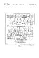
- FIG. 1depicts a block diagram of an exemplary embodiment of the present invention. More specifically, FIG. 1 depicts a functional block diagram of an microcontroller 10 which comprises, among other things, a central processing unit (CPU) 12 , a modular math coprocessor 14 , real time clock circuitry 16 , serial ports 18 , a stack pointer 20 , a block-encryption (DES) engine 22 , timers 24 , a ROM loader circuit 26 , internal registers 28 , instruction and decode circuitry 30 , a CRC generation circuit 32 , interrupt logic 34 , program and data pointer circuitry 36 , a watchdog timer and power control circuit 38 , on-chip memory 40 , and instruction cache circuit 42 on an internal control/data bus 44 .
- CPUcentral processing unit
- DESblock-encryption
- the exemplary integrated circuit 10also comprises some I/O ports 46 and memory management circuitry 48 on internal address bus 50 .
- FIG. 1further depicts reset circuitry 52 , power monitoring circuitry 54 , clock circuitry 56 , program decryption and data encryption circuitry 58 , and a byte-wide bus interface 60 .
- the modular arithmetic accelerator 14is actually a dual co-processor which supports 4096-bit exponentiation and multiplication as well as provides a system clock via a ring oscillator.
- the modular arithmetic acceleratormay contain a 32/16-bit pipelined multiply-accumulate unit, a 16-bit adder/subtracter, a pipelined quotient calculator, a ring oscillator and control logic for exponentiation and multiplication.
- the system clock ring oscillator circuitis not required to be part of the modular arithmetic accelerator, but in the exemplary embodiment it made sense to make slight variations to the arithmetic circuitry to thereby also be able to produce a stable oscillation/system clock signal for the microcontroller.
- the power monitor circuitry 54is used to monitor the voltage being supplied to the exemplary microcontroller 10 . If the power is too high or too low, the power monitor 54 will advise the proper circuit in the microcontroller 10 to reset the microcontroller before a potential malfunction or incorrect calculation occurs.
- the power control block 38may contain temperature sensing circuitry which will determine whether the integrated circuit is operating within a predetermined temperature range.
- the temperature sensing circuitis incorporated into the silicon to monitor chip temperature. If the chip temperature falls below ⁇ 50 C., for example, the temperature sensing circuitry will provide a signal indicating that data in predetermined memory and cache memory locations should be destroyed. If the chip temperature rises above +100 C., for example, the temperature sensing circuitry will initiate a reset and hold the chip in reset until the temperature falls below the maximum operating temperature.
- FIG. 2depicts a second embodiment of the present invention.
- a secure microcontroller 200is depicted.
- This microcontroller 200comprises circuitry that enables it to perform encryption calculations.
- the preferred encryption calculationsare for RSA encryption, but could also be for Rabin, Fiat-Shamir protocol, PGP, DES, or a multitude of public key/private key protocols.
- FIG. 1depicts a second embodiment of the present invention.
- This microcontroller 200comprises circuitry that enables it to perform encryption calculations.
- the preferred encryption calculationsare for RSA encryption, but could also be for Rabin, Fiat-Shamir protocol, PGP, DES, or a multitude of public key/private key protocols.
- FIG. 2depicts internal registers 202 , a CPU 204 , an arithmetic coprocessor 206 , a stack pointer 208 , timer circuitry 210 , ROM loader circuitry 212 , a real-time clock 214 , SRAM circuitry 216 , power management circuitry 218 , a CRC generator 220 , instruction decoding circuitry 222 , interrupt logic circuitry 224 , a program count data pointer circuit 226 , an LCD controller 228 , an instruction cache circuit 230 , program en-/decryptor circuit 232 , a data en-/decryptor 234 , and a block-encryption accelerator 236 all of which are connected and potentially in communication with each other via an internal control/data bus 238 .
- a ring oscillator 241is included in the timing clocks circuitry 240 and is used as the system clock.
- the ring oscillator 241could part of the Arithmetic coprocessor in this exemplary embodiment. (Although not drawn as such in FIG. 2.)
- a temperature circuit 219 and voltage monitor circuit 221may be part of the power management circuitry 218 .
- the CPU 204 and arithmetic coprocessor circuit 206when running, use the ring oscillator 241 .
- the ring oscillator 241runs the basic clocking operations of the microcontroller 200 .
- the ring oscillator 241can be gated on and off as necessary to start and stop.
- oscillation circuits 240may be associated with the integrated circuit.
- a real-time clock crystal oscillatormay provide timing for real-time clock 214 or time stamping functions.
- still yet another oscillatormay be used for I/O timing on a multiwire or one-wire bus connection to the integrated circuit. All the clocks may or may not be asynchronous with each other.
- the oscillator that is most important to the present inventionis the one associated with the circuitry that performs the RSA or encryption calculations in the arithmetic coprocessor 206 .
- the present microcontrollers 10 , 200are attacked via a frequency attack, that is, if an input clock frequency is increased to higher and higher frequencies in order to stress the circuitry to a point where race conditions would develop in the chip in an attempt to result in an improper completion of a calculation task, the present microcontroller's encryption/calculation circuitry would not be affected. Prior art circuitry may not properly terminate the task it is performing when placed in an increased frequency race condition. Under controlled conditions, prior art microcontrollers could be carefully experimented with via a frequency attack so that there results a consistent single-bit error made in the coprocessor circuit 206 .
- Creating a single-bit errorcan be the most powerful attack method because a single-bit permutation is easier to implement in mathematical modeling that could decipher the encryption algorithm. Multiple-bit errors require many permutations to establish a solution as opposed to a single-bit error, one permutation relation.
- the encryption keycan be mathematically determined.
- the erroris created within a prior art microcontroller's arithmetic unit by stressing a prior art integrated circuit and then integrated circuit is allowed to perform an unstressed calculation. The two results are then compared mathematically to determine the secret codes.
- the present exemplary inventionutilizes an on-chip oscillator for providing timing and clock signals to the encryption calculation circuitry.
- the encryption calculations of the exemplary microcontroller 200cannot be stressed into a race condition by an external frequency input.
- An oscillation circuitis monolithically on the chip and is not readily available to an attacker or pirate for adjustment.
- An added virtue of incorporating the oscillation circuit monolithically into the siliconis that it will virtually never oscillate at the same frequency on different chips due to impurities in the silicon and variances in the processing and manufacturing of each chip.
- the oscillators found on similarly manufactured chipsare truly asynchronous and may vary in oscillation speed by a few percent.
- the rest of the circuitrywill also be able to handle the increase of frequency and benefit from having the same temperature characteristics as the oscillation circuitry and thereby staying in “alignment” with the oscillation circuit. That is, all the transistors on the same piece of silicon will be aligned temperature wise, to handle the speed changes of the oscillator.
- the oscillatorcannot be made, via temperature changes, to run at a speed that will out-pace or create a race condition the circuitry it provides a clocking signal to.
- the advantage hereis that the critical encryption calculation circuitry cannot be stressed by an increase of oscillation speed when the oscillator is incorporated into the same silicon as the encryption calculation circuitry.
- the on-board oscillatorwill slow down.
- the increased temperaturewill also slow down the rest of the circuitry on the silicon and thereby track the decrease in oscillation speed.
- the present exemplary microcontrolleralso protects itself against a voltage attack. As the supply voltage goes up, the on-board oscillator will operate faster. The speed increase is generally due to the relationship between supply voltage and the impedance of the FET transistors. The FET impedance typically decreases as the voltage across the FET increases. As a result, an increase of voltage will increase the frequency of the oscillator. Again the voltage relationship will track both the oscillation circuitry and the other circuitry in the integrated circuitry.
- an on-board ring-oscillator which provides a clock signal to the encryption related circuitry 206 , 14provides the benefit of effectively neutralizing “attack methodologies” that focus on attempting to control the frequency of a vulnerable portion of the circuitry 206 , 14 , 12 .
- an attempt to decode data or learn the encryption keysi.e., an attack
- the most vulnerable portion of any circuitis the longest path that data must take or the longest chain of calculations that data must advance through in a single clock cycle.
- the longest path or chain of calculationstakes place in the coprocessor circuitry 206 .
- the preferred embodimentincorporates an oscillator circuit which is designed to substantially look like the math coprocessor circuitry.
- the preferred oscillator circuitis a ring oscillator.
- the ring oscillation circuit and the math coprocessor circuitrysimilar in design, the temperature and voltage characteristics will track each other more closely than if the circuits were substantially different in design. This is not to say that the on-board oscillation circuit must be substantially similar to the circuitry containing the longest data path, but it is preferred. The object is not to have the oscillator outrun the slowest circuit to which it provides clocking signals to.
- the onboard oscillation circuitryit is possible for the onboard oscillation circuitry to be designed similarly to the math coprocessor circuit because the coprocessor is essentially a ripple-carry adder circuit (see FIG. 3 ).
- a ripple-carry adder circuitis generally a path of gates that when fed back on itself will look like a ring oscillator (see FIG. 4) wherein the adder portion is used, generally, as a delay path.
- the circuitis not a standard design for a ring oscillator, but it operates as a ring oscillator. The main importance is that the ring oscillator's frequency output cannot be substantially controlled from outside the integrated circuitry in such a way to speed up or slow down the math coprocessor to thereby attempt to force a calculation error.
- the exemplary embodimentpreferably is capable of thwarting a “voltage attack”.
- a voltage attackis designed to get the microcontroller to make a mistake due to a supply voltage change. The mistake may provide an attacker with enough information to discern the secret keys used in the encryption of data or to decode the data.
- a voltage attackmay be made independent of clock frequency.
- a microcontrolleris designed to operate at a particular voltage or voltages.
- a general purpose microcontrollerlike an 8051 device, may be able to operate at 5 volts at 4 MHZ or at 3 volts at 2 MHZ.
- An attackermay attack a device by lowering its operating voltage, given a particular clock frequency, to get the device to make a mistake or operate improperly. An attacker can take this attack further by only dropping the supply voltage low enough so that the device is not losing data, and then freeze the clock. (Most devices use CMOS technology which is purely static.
- Static CMOSis a good selling feature, but operates in this attacker's favor.
- the deviceis stopped in a static state and then the attacker lowers the supply voltage down to a certain point and then brings it back up.
- the attackeris trying to create a repeatable error by toggling a cell in the coprocessor. If this process is done under carefully controlled conditions a single bit error may be reproducible and predictable.
- a variety of attackscan be developed. For example, an attacker may switch the voltage from high to low then count clock cycles and then lower the voltage, etc.
- a voltage attackis thwarted via a band-gap circuit or voltage window circuit combined with reset capabilities.
- a band gap circuitis utilized to reset a microcontroller if the voltage is too low and the clock is running.
- the band gap circuitrywill reset the device when the clock is or even is not running and when the voltage drops below a predetermined voltage.
- the band gap circuitoperates whether or not the clock is operating.
- any calculation data in the coprocessor 14 , 206is destroyed.
- the predetermined voltageis set at a voltage above where the coprocessor may miscalculate data. Instead of producing a potential single bit error, which the attacker wants, all the bits are reset to zero.
- An added advantage of the preferred embodimentis that an onboard oscillator exists to carry out the reset function. That is, even if an external clock is being used to clock data in and out of the device and an external power supply is used to power the device, the combination of the internal oscillator and the band gap circuit can be used to reset the part if the voltage supply drops below a particular voltage. It is important to point out that an onboard oscillator is useful against a low voltage attack but is not necessary. The coprocessor can be reset without the aid of the onboard oscillator as well.
- a high-voltage attackis a slightly different matter than a low voltage attack. Stressing the voltage upward can cause problems in the silicon circuitry of the microcontroller.
- One object of a high-voltage attackwould be to increase the frequency of the switching within the circuitry to get a gate to switch too soon and encourage an incorrect calculation.
- An onboard oscillator circuitsuch as the ring oscillator of the present exemplary embodiment, will help thwart that problem by providing a usable clock frequency regardless of the voltage.
- an exemplary embodimentmay have a high-voltage detection circuit which can protect the chip from a high-voltage frequency relationship attack. When the supply voltage is too high, or above a predetermined voltage, the device will reset and destroy any calculation data in the coprocessor portion of the microcontroller.
- a voltage window with a high and low settingfor example 6.5 volts and 2.5 volts can be connected to reset the math coprocessor, arithmetic and/or, microcontroller circuitry if the voltage is above or below the voltage window settings.
- a circuitwould be found in the power monitoring circuitry 54 , 218 .
- a device resetoccurs, that is, all states that are temporary states on the chip should be reset; second, all states that are permanent states in memory or a volatile state should be backed up by a back-up power source such as a battery; and third, the clock will be stopped.
- the supply voltage in an exemplary microcontrollergoes above a predetermined voltage first, a reset of all temporary states occurs and second, all states that are permanent and volatile, such as SRAM, are switched to being battery backed so that they will not be changed or destroyed by an overvoltage; and third the clock is stopped.
- the deviceshould be allowed to destroy itself so as to be nonfunctional.
- thermal attackWith respect to a thermal attack, first theoretically the charge on a RAM cell can be preserved and detected if a device is quickly frozen in liquid nitrogen. Secondly, a thermal attack can be viewed as similar to a voltage attack in that the device is stressed. As the temperature increases the elements of the device will speed up. The object of the second thermal attack is to speed or slow the part so that it will make a mistake. A thermal attack can be combined with a voltage or a frequency attack.
- a temperature sensing circuitis incorporated into the silicon circuitry.
- the temperature sensorsenses, for example, when the temperature drops below ⁇ 100 ° C. When the temperature drops below the predetermined temperature, the temperature sensor will send a trip signal to erase the static RAM instantly. Any secret keys or other information that should not be extracted from the memory will be destroyed.
- the temperature sensing circuitrycan be designed to trigger at any predetermined temperature and can be set to erase any memory location. latch, flip-flop, register, etc., when triggered. The object here is to destroy “secret” information prior to the memory location being frozen.
- an exemplary devicecan also have an operating temperature window in order to thwart an attack that attempts to speed up or slow down the device using temperature.
- the temperature windowwill operate similarly to the voltage window described above. That is, instead of monitoring voltage, the temperature window will check to make sure the device is operating in a temperature range between, for example, ⁇ 50 ° C. and 90° C. There is no reason for perfect accuracy in the temperature sensor so +/ ⁇ 5° C. to 10° C. accuracy is fine.
- the preferred present exemplary embodimentis battery backed.
- the batteryis preferably a very small battery, thus, the temperature sensing portion of the circuitry must be very low power and consume on the average, less than 100 picoamps.
- the temperature sensing devicemust sense temperature often enough to protect the device from a temperature attack.
- the temperature sensing circuitrywill use less than 100 picoamps on average. This is done by cycling the temperature sensing circuitry on and off. On a first clock cycle the temperature sensing circuitry is powered up, warmed up and a temperature reading is taken. On a second or next clock cycle the temperature sensed result is latched and action is taken accordingly. If the temperature is too cold (below a predetermined temperature), the RAM memory is erased instantly. If the temperature is outside the temperature window, the device will reset any calculation being performed and the clocking oscillator will stop oscillating.
- the temperature sensing circuitryis turned on for short periods of time 2 to 3 clock cycles and left off for long periods of time ranging from a 100th of a second to a minute.
- the resultis that the temperature sensing device averages a power requirement in the 100 picoamp range instead of the 100 microamp range.
- the temperature-sensing circuitrymust be operated primarily off of battery power because a microcontroller may rarely be powered up. Thus, a designer cannot depend on energy from outside the microcontroller because the microcontroller may be infrequently used. Ideally, the exemplary embodiment will have an operating battery life of about 10 years ⁇ 2 years. Circuitry can be added to the microcontroller to place it in reset if the backup-battery power is removed.
- the present exemplary microcontrollermoves closer to becoming an error free device that is very difficult to pirate.
- the encryption capabilities of an exemplary microcontrollerare also moved toward being more secure.
- the internal clock generation block 300can be any suitable clock generation circuit that does not require connections to an external crystal or other external oscillation source.
- the clock generation circuitis a ring oscillator.
- the output of the ring oscillatorshould, at least, provide the clocking signals for the coprocessor circuitry and possibly the CPU circuitry.
- the internal clock generation circuit 300it is not required that the internal clock generation circuit 300 be integrated with the math coprocessor circuit. Indeed, the clock generation circuit can be anywhere on the integrated circuit so long as it is incorporated as part of the microcontroller or microprocessor integrated circuitry.
- FIG. 4depicts an exemplary oscillation/clock circuit 300 . It is important that the oscillation/clock speed of the oscillation circuit 300 never exceed the fastest clock rate that the math coprocessor circuit 206 can handle.
- a ring oscillatoris implemented as a carry-chain circuitry 402 that is similar to that found in the exemplary coprocessor circuitry. Additional delay or padding circuitry 404 is incorporated into the circuit to make the progation time of the ring oscillator longer than that of the exemplary coprocessor circuitry 206 .
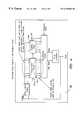
- FIG. 5depicts an exemplary block diagram of a power management circuit 218 which includes a temperature monitoring block 500 .
- the temperature monitoring block 500includes a temperature window circuit to detect predetermined high and low temperatures.
- the temperature monitoring circuitryalso determines if the temperature is an extremely cold temperature, such as liquid nitrogen.
- a voltage monitoring block 502is also shown.
- the voltage monitoring blockis connected to ground (GND), power (VCC), and the battery backup source (VBAT).
- the voltagesare monitored with a band-gap circuit voltage window circuit or other voltage sensing circuity.
- a clock multiplier/synchronizer block 504is shown.
- the clock multiplier/synthesizercan be utilized to monitor an external clock frequency.
- Each of the monitoring circuitsprovide an alarm signal to the reset and erase-RAM control block 506 , if a frequency, voltage or temperature is detected outside of a predetermined range.
- the reset and erase control block 506provides reset and wipe RAM signals for initiating a microcontroller reset, initiating a RAM-erase function or both depending on the alarm conditions.
- the present inventionis significant in the microcontroller area of technology.
- the present inventionis believed to be especially effective when configured an employed as described herein.
- numerous variations and substitutionsmay be made in the invention and its use and configuration to achieve substantially the same results as achieved by the embodiments and, in particular, the preferred embodiment described herein.
- Each variationis intended to be included in the description herein and forms a part of the present invention.
Landscapes
- Engineering & Computer Science (AREA)
- Theoretical Computer Science (AREA)
- Physics & Mathematics (AREA)
- General Physics & Mathematics (AREA)
- Computer Hardware Design (AREA)
- General Engineering & Computer Science (AREA)
- Mathematical Physics (AREA)
- Computer Security & Cryptography (AREA)
- Computing Systems (AREA)
- Quality & Reliability (AREA)
- Software Systems (AREA)
- Microelectronics & Electronic Packaging (AREA)
- Automation & Control Theory (AREA)
- Semiconductor Integrated Circuits (AREA)
Abstract
Description
1. Field of the Invention
This Invention relates to hardware designed into silicon circuitry which prevents the circuitry from being forced to operate outside of predetermined parameters. More specifically, the present invention relates to hardware circuitry which may detect over or under voltage conditions, high- or low-speed clocks, and over or under temperature conditions. The circuitry may reset or shut down the silicon circuitry in response to such detections.
2. Description of Related Art
Microcontrollers have become commonplace in today's society. Over time microcontrollers have accommodated and provided a wide variety of solutions to various problems in the electronic and automation industries. At present, microcontrollers are beginning to be placed in devices or used as devices that perform secure transfers of money, monetary equivalents and secure information.
As a result of using microcontrollers for transferring and handling secure information and data, there are people dedicated to “breaking the code” or mathematically evaluating the secure data transfers in order to determine the secrets and proprietary techniques of the secure data transfers.
Smart cards, for example, have been “attacked” by varying the frequency to the microprocessor and the coprocessor at specific times. The frequency can be increased to produce race conditions in the integrated circuit that will make the circuit operate improperly due to the limited time between rising and falling edges of the clock signal. Calculation errors may result. A calculation error resulting from such a race condition can be compared with a similar calculation made with a good/correct result to correspondingly resolve the secret key(s) associated with the calculation and thereby defeat the security of the integrated circuit.
In the area of cryptography, an important article was written entitled “On the Importance of Checking Cryptographic Protocols for Faults”, Dan Boneh, Richard A. DeMillo, Richard J. Lipton, Security and Cryptography Research Group, Bellcore, 1997(hereinafter “the Bellcore article”). The Bellcore article discusses attack techniques targeted at RSA encryption and Rabin signatures. In essence the Bellcore article indicates that from time to time hardware which performs RSA encryption calculations may introduce errors. If the errors are found or can be forced by an attacker, then the RSA code may be broken by using various algorithms. Thus, there is a need for integrated circuits which perform encryption calculations that have means for stopping or limiting the circuitry from being stressed into introducing errors into calculations.
Exemplary embodiments of the present invention overcome drawbacks of past secure microcontroller designs and integrated circuitry designs by providing hardware mechanisms which prevent a silicon circuit from operating outside its proper bounds of design. In doing so, the integrated circuit, and more particularly, the microcontroller is prevented from providing or performing an incorrect calculation result under certain conditions.
Three preferred hardware mechanisms can be incorporated into the present exemplary embodiment which will each prevent the silicon circuitry from being stressed to a point of performing an invalid task. An onboard oscillation circuit built into the silicon circuit can be used to provide a system clock and prevent race clocking conditions. An onboard temperature sensing circuit, which senses when the integrated circuit is operating outside of a predetermined temperature range, can be incorporated into the present invention to stop the integrated circuit from making an incorrect calculation due to extreme temperatures. Furthermore, a voltage sensing circuit can be incorporated into the present embodiment and sense when the voltage provided to the silicon circuit is above or below a predetermined temperature range and thereby stop the silicon circuitry from being stressed to produce an invalid or incorrect calculation result.
A more complete understanding of the method and apparatus of the present invention may be had by reference to the following Detailed Description when taken in conjunction with the accompanying Drawings, wherein;
FIG. 1 is a functional block diagram of an exemplary integrated circuit comprising aspects of the present invention;
FIG. 2 is a functional block diagram of another exemplary embodiment of a integrated circuit comprising aspects of the present invention;
FIG. 3 is block diagram of a arithmetic coprocessor associated with an exemplary integrated circuit;
FIG. 4 is a block diagram of an exemplary oscillation/ system clock circuit built into an exemplary embodiment of the present invention; and
FIG. 5 is a block diagram of an exemplary control circuit incorporated into a present exemplary embodiment.
Although the present invention can be incorporated into a wide variety of silicon based devices or integrated circuits, an exemplary embodiment of the present invention will be discussed in this application. The present invention is related to a microcontroller combined with an math coprocessor that may have encryption capabilities. It is important that the microcontroller is protected from being stressed via frequency, temperature and voltage variations that may force the circuit to operate incorrectly.
In essence, hardware circuitry is added to an integrated circuit to prevent the circuitry from operating outside of its proper bounds of operation. In doing so, for example, a microprocessor with a coprocessor is not stressed into outputting an incorrect value as a calculation result.
FIG. 1 depicts a block diagram of an exemplary embodiment of the present invention. More specifically, FIG. 1 depicts a functional block diagram of anmicrocontroller 10 which comprises, among other things, a central processing unit (CPU)12, amodular math coprocessor 14, realtime clock circuitry 16,serial ports 18, astack pointer 20, a block-encryption (DES)engine 22,timers 24, aROM loader circuit 26,internal registers 28, instruction anddecode circuitry 30, aCRC generation circuit 32,interrupt logic 34, program anddata pointer circuitry 36, a watchdog timer andpower control circuit 38, on-chip memory 40, andinstruction cache circuit 42 on an internal control/data bus 44. The exemplaryintegrated circuit 10 also comprises some I/O ports 46 andmemory management circuitry 48 oninternal address bus 50. FIG. 1 further depictsreset circuitry 52, power monitoring circuitry54,clock circuitry 56, program decryption anddata encryption circuitry 58, and a byte-wide bus interface 60.
In the preferred embodiment, the modulararithmetic accelerator 14 is actually a dual co-processor which supports 4096-bit exponentiation and multiplication as well as provides a system clock via a ring oscillator. The modular arithmetic accelerator may contain a 32/16-bit pipelined multiply-accumulate unit, a 16-bit adder/subtracter, a pipelined quotient calculator, a ring oscillator and control logic for exponentiation and multiplication. The system clock ring oscillator circuit is not required to be part of the modular arithmetic accelerator, but in the exemplary embodiment it made sense to make slight variations to the arithmetic circuitry to thereby also be able to produce a stable oscillation/system clock signal for the microcontroller.
The power monitor circuitry54 is used to monitor the voltage being supplied to theexemplary microcontroller 10. If the power is too high or too low, the power monitor54 will advise the proper circuit in themicrocontroller 10 to reset the microcontroller before a potential malfunction or incorrect calculation occurs.
Although not specifically shown in FIG. 1, thepower control block 38 may contain temperature sensing circuitry which will determine whether the integrated circuit is operating within a predetermined temperature range. The temperature sensing circuit is incorporated into the silicon to monitor chip temperature. If the chip temperature falls below −50 C., for example, the temperature sensing circuitry will provide a signal indicating that data in predetermined memory and cache memory locations should be destroyed. If the chip temperature rises above +100 C., for example, the temperature sensing circuitry will initiate a reset and hold the chip in reset until the temperature falls below the maximum operating temperature.
FIG. 2 depicts a second embodiment of the present invention. Here asecure microcontroller 200 is depicted. Thismicrocontroller 200 comprises circuitry that enables it to perform encryption calculations. The preferred encryption calculations are for RSA encryption, but could also be for Rabin, Fiat-Shamir protocol, PGP, DES, or a multitude of public key/private key protocols. FIG. 2 depictsinternal registers 202, aCPU 204, anarithmetic coprocessor 206, astack pointer 208,timer circuitry 210,ROM loader circuitry 212, a real-time clock 214,SRAM circuitry 216,power management circuitry 218, aCRC generator 220,instruction decoding circuitry 222,interrupt logic circuitry 224, a program countdata pointer circuit 226, anLCD controller 228, aninstruction cache circuit 230, program en-/decryptor circuit 232, a data en-/decryptor 234, and a block-encryption accelerator 236 all of which are connected and potentially in communication with each other via an internal control/data bus 238.
Aring oscillator 241 is included in thetiming clocks circuitry 240 and is used as the system clock. Thering oscillator 241 could part of the Arithmetic coprocessor in this exemplary embodiment. (Although not drawn as such in FIG. 2.) Atemperature circuit 219 andvoltage monitor circuit 221 may be part of thepower management circuitry 218.
TheCPU 204 andarithmetic coprocessor circuit 206, when running, use thering oscillator 241. Thering oscillator 241 runs the basic clocking operations of themicrocontroller 200. Thering oscillator 241 can be gated on and off as necessary to start and stop.
If thepresent microcontrollers coprocessor circuit 206. Creating a single-bit error can be the most powerful attack method because a single-bit permutation is easier to implement in mathematical modeling that could decipher the encryption algorithm. Multiple-bit errors require many permutations to establish a solution as opposed to a single-bit error, one permutation relation.
If a one-bit error is established and a proper calculation is performed, then is it possible the encryption key can be mathematically determined. The error is created within a prior art microcontroller's arithmetic unit by stressing a prior art integrated circuit and then integrated circuit is allowed to perform an unstressed calculation. The two results are then compared mathematically to determine the secret codes.
The present exemplary invention, as stated above, utilizes an on-chip oscillator for providing timing and clock signals to the encryption calculation circuitry. Thus, the encryption calculations of theexemplary microcontroller 200 cannot be stressed into a race condition by an external frequency input. An oscillation circuit is monolithically on the chip and is not readily available to an attacker or pirate for adjustment. An added virtue of incorporating the oscillation circuit monolithically into the silicon is that it will virtually never oscillate at the same frequency on different chips due to impurities in the silicon and variances in the processing and manufacturing of each chip. The oscillators found on similarly manufactured chips are truly asynchronous and may vary in oscillation speed by a few percent.
Although temperature and voltage variances will be discussed later, at this point it is important to point out their effect on an on-chip oscillator. Temperature impacts the preferred oscillation circuit, a ring oscillator, in much the same way it impacts CMOS silicon circuitry in general. As temperature goes down, transistors become more efficient and can switch or operate at faster speeds. Thus, as the temperature decreases, the on-chip oscillator for the arithmetic or encryption calculation circuitry will increase its output frequency (i.e., run faster). Another advantage of the present embodiment is that the oscillation circuitry is on the same piece of silicon as the rest of the circuitry that utilizes the oscillation circuitry. As the oscillation circuitry increases its output frequency due to a temperature change, the rest of the circuitry will also be able to handle the increase of frequency and benefit from having the same temperature characteristics as the oscillation circuitry and thereby staying in “alignment” with the oscillation circuit. That is, all the transistors on the same piece of silicon will be aligned temperature wise, to handle the speed changes of the oscillator. The oscillator cannot be made, via temperature changes, to run at a speed that will out-pace or create a race condition the circuitry it provides a clocking signal to. The advantage here is that the critical encryption calculation circuitry cannot be stressed by an increase of oscillation speed when the oscillator is incorporated into the same silicon as the encryption calculation circuitry.
It should be understood that the present invention operates to thwart full-chip attack methodologies rather than pin-point style attack methodologies of discrete circuits or areas on an integrated circuit. We note that pin-point attack methodologies tend to be very expensive and generally theoretical.
As the temperature of the silicon increases, the on-board oscillator will slow down. Of course, the increased temperature will also slow down the rest of the circuitry on the silicon and thereby track the decrease in oscillation speed.
The present exemplary microcontroller also protects itself against a voltage attack. As the supply voltage goes up, the on-board oscillator will operate faster. The speed increase is generally due to the relationship between supply voltage and the impedance of the FET transistors. The FET impedance typically decreases as the voltage across the FET increases. As a result, an increase of voltage will increase the frequency of the oscillator. Again the voltage relationship will track both the oscillation circuitry and the other circuitry in the integrated circuitry.
From a “control of frequency” standpoint an on-board ring-oscillator which provides a clock signal to the encryption relatedcircuitry circuitry coprocessor circuitry 206. When performing an encryption calculation, such as a modulo math calculation in themath coprocessor 206 the data traversing the longest path through thecoprocessor 206 is the most vulnerable to an attack from a user who is attempting to break the encryption code. To confuse an attacker, the preferred embodiment incorporates an oscillator circuit which is designed to substantially look like the math coprocessor circuitry.
The preferred oscillator circuit is a ring oscillator. By making the ring oscillation circuit and the math coprocessor circuitry similar in design, the temperature and voltage characteristics will track each other more closely than if the circuits were substantially different in design. This is not to say that the on-board oscillation circuit must be substantially similar to the circuitry containing the longest data path, but it is preferred. The object is not to have the oscillator outrun the slowest circuit to which it provides clocking signals to.
In the exemplary embodiment, it is possible for the onboard oscillation circuitry to be designed similarly to the math coprocessor circuit because the coprocessor is essentially a ripple-carry adder circuit (see FIG.3). A ripple-carry adder circuit is generally a path of gates that when fed back on itself will look like a ring oscillator (see FIG. 4) wherein the adder portion is used, generally, as a delay path. The circuit is not a standard design for a ring oscillator, but it operates as a ring oscillator. The main importance is that the ring oscillator's frequency output cannot be substantially controlled from outside the integrated circuitry in such a way to speed up or slow down the math coprocessor to thereby attempt to force a calculation error.
Focusing on voltage, the exemplary embodiment preferably is capable of thwarting a “voltage attack”. A voltage attack is designed to get the microcontroller to make a mistake due to a supply voltage change. The mistake may provide an attacker with enough information to discern the secret keys used in the encryption of data or to decode the data.
Generally, a voltage attack may be made independent of clock frequency. A microcontroller is designed to operate at a particular voltage or voltages. For example, a general purpose microcontroller, like an 8051 device, may be able to operate at 5 volts at 4 MHZ or at 3 volts at 2 MHZ. An attacker may attack a device by lowering its operating voltage, given a particular clock frequency, to get the device to make a mistake or operate improperly. An attacker can take this attack further by only dropping the supply voltage low enough so that the device is not losing data, and then freeze the clock. (Most devices use CMOS technology which is purely static. Static CMOS is a good selling feature, but operates in this attacker's favor.) The device is stopped in a static state and then the attacker lowers the supply voltage down to a certain point and then brings it back up. The attacker is trying to create a repeatable error by toggling a cell in the coprocessor. If this process is done under carefully controlled conditions a single bit error may be reproducible and predictable. A variety of attacks can be developed. For example, an attacker may switch the voltage from high to low then count clock cycles and then lower the voltage, etc.
In the present exemplary embodiment, a voltage attack is thwarted via a band-gap circuit or voltage window circuit combined with reset capabilities. Usually a band gap circuit is utilized to reset a microcontroller if the voltage is too low and the clock is running. In the present exemplary embodiment the band gap circuitry will reset the device when the clock is or even is not running and when the voltage drops below a predetermined voltage. The band gap circuit operates whether or not the clock is operating. When the device is reset, any calculation data in thecoprocessor
An added advantage of the preferred embodiment is that an onboard oscillator exists to carry out the reset function. That is, even if an external clock is being used to clock data in and out of the device and an external power supply is used to power the device, the combination of the internal oscillator and the band gap circuit can be used to reset the part if the voltage supply drops below a particular voltage. It is important to point out that an onboard oscillator is useful against a low voltage attack but is not necessary. The coprocessor can be reset without the aid of the onboard oscillator as well.
A high-voltage attack is a slightly different matter than a low voltage attack. Stressing the voltage upward can cause problems in the silicon circuitry of the microcontroller. One object of a high-voltage attack would be to increase the frequency of the switching within the circuitry to get a gate to switch too soon and encourage an incorrect calculation. An onboard oscillator circuit, such as the ring oscillator of the present exemplary embodiment, will help thwart that problem by providing a usable clock frequency regardless of the voltage. Furthermore, an exemplary embodiment may have a high-voltage detection circuit which can protect the chip from a high-voltage frequency relationship attack. When the supply voltage is too high, or above a predetermined voltage, the device will reset and destroy any calculation data in the coprocessor portion of the microcontroller.
Thus, in an exemplary embodiment of the present invention, a voltage window with a high and low setting, for example 6.5 volts and 2.5 volts can be connected to reset the math coprocessor, arithmetic and/or, microcontroller circuitry if the voltage is above or below the voltage window settings. Such a circuit would be found in thepower monitoring circuitry 54,218.
If the voltage is too high the device may begin to malfunction and thereby produce a calculation error. Of course, if the voltage is much to high irreparable harm will result.
In an exemplary microcontroller, when the voltage goes below a predetermined voltage such as 2.5 volts, three things happen. First, a device reset occurs, that is, all states that are temporary states on the chip should be reset; second, all states that are permanent states in memory or a volatile state should be backed up by a back-up power source such as a battery; and third, the clock will be stopped. Similarly, if the supply voltage in an exemplary microcontroller goes above a predetermined voltage first, a reset of all temporary states occurs and second, all states that are permanent and volatile, such as SRAM, are switched to being battery backed so that they will not be changed or destroyed by an overvoltage; and third the clock is stopped. At a predetermined overvoltage, the device should be allowed to destroy itself so as to be nonfunctional.
With respect to a thermal attack, first theoretically the charge on a RAM cell can be preserved and detected if a device is quickly frozen in liquid nitrogen. Secondly, a thermal attack can be viewed as similar to a voltage attack in that the device is stressed. As the temperature increases the elements of the device will speed up. The object of the second thermal attack is to speed or slow the part so that it will make a mistake. A thermal attack can be combined with a voltage or a frequency attack.
In the exemplary embodiment, a temperature sensing circuit is incorporated into the silicon circuitry. The temperature sensor senses, for example, when the temperature drops below −100° C. When the temperature drops below the predetermined temperature, the temperature sensor will send a trip signal to erase the static RAM instantly. Any secret keys or other information that should not be extracted from the memory will be destroyed. The temperature sensing circuitry can be designed to trigger at any predetermined temperature and can be set to erase any memory location. latch, flip-flop, register, etc., when triggered. The object here is to destroy “secret” information prior to the memory location being frozen.
Furthermore, an exemplary device can also have an operating temperature window in order to thwart an attack that attempts to speed up or slow down the device using temperature. The temperature window will operate similarly to the voltage window described above. That is, instead of monitoring voltage, the temperature window will check to make sure the device is operating in a temperature range between, for example, −50° C. and 90° C. There is no reason for perfect accuracy in the temperature sensor so +/−5° C. to 10° C. accuracy is fine.
If the temperature goes outside the temperature window, the device will reset and the on-board oscillator will stop clocking the device. It is very important that the temperature sensing circuit uses a minimal amount of power. The preferred present exemplary embodiment is battery backed. The battery is preferably a very small battery, thus, the temperature sensing portion of the circuitry must be very low power and consume on the average, less than 100 picoamps. On the other hand, the temperature sensing device must sense temperature often enough to protect the device from a temperature attack.
In the preferred embodiment, the temperature sensing circuitry will use less than 100 picoamps on average. This is done by cycling the temperature sensing circuitry on and off. On a first clock cycle the temperature sensing circuitry is powered up, warmed up and a temperature reading is taken. On a second or next clock cycle the temperature sensed result is latched and action is taken accordingly. If the temperature is too cold (below a predetermined temperature), the RAM memory is erased instantly. If the temperature is outside the temperature window, the device will reset any calculation being performed and the clocking oscillator will stop oscillating.
In order to save energy the temperature sensing circuitry is turned on for short periods of time 2 to 3 clock cycles and left off for long periods of time ranging from a 100th of a second to a minute. The result is that the temperature sensing device averages a power requirement in the 100 picoamp range instead of the 100 microamp range.
The temperature-sensing circuitry must be operated primarily off of battery power because a microcontroller may rarely be powered up. Thus, a designer cannot depend on energy from outside the microcontroller because the microcontroller may be infrequently used. Ideally, the exemplary embodiment will have an operating battery life of about 10 years±2 years. Circuitry can be added to the microcontroller to place it in reset if the backup-battery power is removed.
As a result of the above described temperature sensing capabilities, voltage sensing capabilities and the on-board system clock, the present exemplary microcontroller moves closer to becoming an error free device that is very difficult to pirate. The encryption capabilities of an exemplary microcontroller are also moved toward being more secure.
Referring now to FIG. 3, a functional block diagram of anexemplary math coprocessor 206 is depicted. The internalclock generation block 300 can be any suitable clock generation circuit that does not require connections to an external crystal or other external oscillation source. In the exemplary device the clock generation circuit is a ring oscillator. The output of the ring oscillator should, at least, provide the clocking signals for the coprocessor circuitry and possibly the CPU circuitry. Furthermore, it is not required that the internalclock generation circuit 300 be integrated with the math coprocessor circuit. Indeed, the clock generation circuit can be anywhere on the integrated circuit so long as it is incorporated as part of the microcontroller or microprocessor integrated circuitry.
FIG. 4 depicts an exemplary oscillation/clock circuit 300. It is important that the oscillation/clock speed of theoscillation circuit 300 never exceed the fastest clock rate that themath coprocessor circuit 206 can handle. In the exemplary oscillation circuit, a ring oscillator is implemented as a carry-chain circuitry 402 that is similar to that found in the exemplary coprocessor circuitry. Additional delay orpadding circuitry 404 is incorporated into the circuit to make the progation time of the ring oscillator longer than that of theexemplary coprocessor circuitry 206.
FIG. 5 depicts an exemplary block diagram of apower management circuit 218 which includes atemperature monitoring block 500. Thetemperature monitoring block 500 includes a temperature window circuit to detect predetermined high and low temperatures. The temperature monitoring circuitry also determines if the temperature is an extremely cold temperature, such as liquid nitrogen. Avoltage monitoring block 502 is also shown. The voltage monitoring block is connected to ground (GND), power (VCC), and the battery backup source (VBAT). The voltages are monitored with a band-gap circuit voltage window circuit or other voltage sensing circuity.
A clock multiplier/synchronizer block 504 is shown. The clock multiplier/synthesizer can be utilized to monitor an external clock frequency. Each of the monitoring circuits provide an alarm signal to the reset and erase-RAM control block 506, if a frequency, voltage or temperature is detected outside of a predetermined range. The reset and erase control block506 provides reset and wipe RAM signals for initiating a microcontroller reset, initiating a RAM-erase function or both depending on the alarm conditions.
As is clearly seen, the present invention is significant in the microcontroller area of technology. The present invention is believed to be especially effective when configured an employed as described herein. However, those skilled in the art will readily recognize that numerous variations and substitutions may be made in the invention and its use and configuration to achieve substantially the same results as achieved by the embodiments and, in particular, the preferred embodiment described herein. Each variation is intended to be included in the description herein and forms a part of the present invention. The foregoing detailed description is, thus, to be clearly understood as being given by way of illustration and example only, the spirit and scope of the present invention being limited solely by the appended claims.
Claims (12)
1. An integrated circuit comprising:
general circuitry for performing a predetermined function;
protection circuitry, connected to said general circuitry, for resetting said general circuitry if said general circuitry is forced to operate outside of at least one predetermined parameter, said protection circuitry comprising:
control circuitry for providing said resetting signal to said general circuitry;
voltage-sensing circuitry for sensing an over voltage or under-voltage condition;
temperature sensing circuitry for sensing an under temperature or over-temperature, condition; and
an internal system clock which does not connect an off chip oscillation source; said voltage-sensing circuitry and temperature-sensing circuitry being connected to said control circuitry.
2. The integrated circuit of claim1, wherein said general circuitry is a microcontroller circuit.
3. The integrated circuit of claim1, wherein said general circuitry is at least one of an arithmetic logic unit circuit, a math coprocessor circuit, and a circuit designed to perform encryption calculations.
4. The integrated ciruitry of claim1, wherein said temperature-sensing circuit is battery backed.
5. A microcontroller integrated circuit comprising:
a central processing unit;
an arithmetic coprocessor connected by a bus to said central processing unit;
an on-board oscillation circuit for providing clock signals to at least said arithmetic coprocessor;
a temperature-sensing circuit for providing a reset signal to said arithmetic coprocessor if the temperature is outside of a predetermined temperature window and for providing an erase signal at least one memory location if the temperature is below a predetermined temperature; and
a voltage-sensing circuit for providing a reset signal to said arithmetic coprocessor if a supply voltage is outside of a predetermined voltage window.
6. The microcontroller integrated circuit of claim5, wherein said microcontroller is designed for use with encrypted data.
7. The microcontroller integrated circuit of claim5, wherein at least a part of said temperature-sensing circuit is battery backed.
8. The microcontroller integrated circuit of claim5, wherein said on-board oscillation circuit is designed similarly to said arithmetic coprocessor.
9. The microcontroller integrated circuit of claim5, wherein said arithmetic coprocessor is a modulo-math coprocessor circuit.
10. An integrated circuit capable of performing encryption calculations, said integrated circuit comprising:
temperature-sensing circuitry for sensing temperature and providing a first reset signal if the temperature is outside of a predetermined temperature range;
voltage-sensing circuitry for sensing a supply voltage and providing a second reset signal if the supply voltage is outside of a predetermined voltage range;
an on-board oscillation circuit for providing a clock signal to at least a portion of said integrated circuit, said oscillation circuit does not receive oscillation signals originating from off said integrated circuit, said first reset signal and said second reset signal being utilized to reset at least a arithmetic circuit on said integrated circuit.
11. The integrated circuit of claim10, wherein said arithmetic circuit performs data encryption calculations.
12. The integrated circuit of claim10, wherein said temperature-sensing circuit provides a erase memory signal if said temperature is below a predetermined temperature.
Priority Applications (1)
| Application Number | Priority Date | Filing Date | Title |
|---|---|---|---|
| US09/133,946US6330668B1 (en) | 1998-08-14 | 1998-08-14 | Integrated circuit having hardware circuitry to prevent electrical or thermal stressing of the silicon circuitry |
Applications Claiming Priority (1)
| Application Number | Priority Date | Filing Date | Title |
|---|---|---|---|
| US09/133,946US6330668B1 (en) | 1998-08-14 | 1998-08-14 | Integrated circuit having hardware circuitry to prevent electrical or thermal stressing of the silicon circuitry |
Publications (1)
| Publication Number | Publication Date |
|---|---|
| US6330668B1true US6330668B1 (en) | 2001-12-11 |
Family
ID=22461040
Family Applications (1)
| Application Number | Title | Priority Date | Filing Date |
|---|---|---|---|
| US09/133,946Expired - LifetimeUS6330668B1 (en) | 1998-08-14 | 1998-08-14 | Integrated circuit having hardware circuitry to prevent electrical or thermal stressing of the silicon circuitry |
Country Status (1)
| Country | Link |
|---|---|
| US (1) | US6330668B1 (en) |
Cited By (32)
| Publication number | Priority date | Publication date | Assignee | Title |
|---|---|---|---|---|
| US20020023241A1 (en)* | 2000-04-28 | 2002-02-21 | Hideki Kabune | Electronic control apparatus having a plurality of power source circuits |
| US6460092B1 (en)* | 1999-05-26 | 2002-10-01 | Industrial Technology Research Institute | Integrated circuit for distributed-type input/output control |
| US20030060964A1 (en)* | 2001-09-27 | 2003-03-27 | Yoshifumi Ozeki | Electronic control unit for vehicle having operation monitoring function and fail-safe function |
| US6552945B2 (en)* | 1999-08-30 | 2003-04-22 | Micron Technology, Inc. | Method for storing a temperature threshold in an integrated circuit, method for storing a temperature threshold in a dynamic random access memory, method of modifying dynamic random access memory operation in response to temperature, programmable temperature sensing circuit and memory integrated circuit |
| US20030204777A1 (en)* | 2002-04-30 | 2003-10-30 | Kojori Hassan A. | Control sequencing and prognostics health monitoring for digital power conversion and load management |
| US20030218887A1 (en)* | 2002-04-30 | 2003-11-27 | Kojori Hassan A. | Synchronous and bi-directional variable frequency power conversion systems |
| US20040049662A1 (en)* | 2001-03-09 | 2004-03-11 | Marcus Janke | Device and method for performing operations at a variable speed |
| US20040128528A1 (en)* | 2002-12-31 | 2004-07-01 | Poisner David I. | Trusted real time clock |
| EP1503288A3 (en)* | 2003-07-09 | 2005-02-09 | St Microelectronics S.A. | Error detection cell for integrated processors |
| US20050172139A1 (en)* | 2003-02-20 | 2005-08-04 | Hirofumi Kanai | Information processing system and information processing method |
| US6985581B1 (en)* | 1999-05-06 | 2006-01-10 | Intel Corporation | Method and apparatus to verify circuit operating conditions |
| US20060090211A1 (en)* | 2003-01-10 | 2006-04-27 | Koninklijke Phillips Electronics N.C. | Circuit arrangement and method for protecting electronic components against illicit manipulation |
| WO2006069944A1 (en)* | 2004-12-23 | 2006-07-06 | Siemens Aktiengesellschaft | Electronic device having temperature distribution determination possibilities |
| US7134025B1 (en) | 2002-03-29 | 2006-11-07 | Xilinx, Inc. | Methods and circuits for preventing the overwriting of memory frames in programmable logic devices |
| EP1728137A1 (en)* | 2004-03-24 | 2006-12-06 | Siemens Aktiengesellschaft | Integrated circuit device |
| US20070069875A1 (en)* | 2005-09-28 | 2007-03-29 | Corrent Corporation | Tamper monitor circuit |
| DE102004030543B4 (en)* | 2003-10-21 | 2009-02-05 | Samsung Electronics Co., Ltd., Suwon | Magnetic storage / resistive storage with a calibration system |
| US20090292894A1 (en)* | 2008-05-24 | 2009-11-26 | Via Technologies, Inc | Microprocessor having internal secure memory |
| US20090289321A1 (en)* | 2008-05-21 | 2009-11-26 | Mindspeed Technologies, Inc | Thermal sensing and reset protection for an integrated circuit chip |
| EP2124165A3 (en)* | 2008-05-24 | 2009-12-02 | VIA Technologies, Inc. | Microprocessor having a secure execution mode with provisions for monitoring, indication, and managing security levels |
| US20100293439A1 (en)* | 2009-05-18 | 2010-11-18 | David Flynn | Apparatus, system, and method for reconfiguring an array to operate with less storage elements |
| WO2011018414A3 (en)* | 2009-08-14 | 2011-12-01 | Intrinsic Id B.V. | Physically unclonable function with tamper prevention and anti-aging system |
| US20120033810A1 (en)* | 2002-04-16 | 2012-02-09 | Massachusetts Institute Of Technology | Authentication of integrated circuits |
| EP2456247A1 (en)* | 2010-09-29 | 2012-05-23 | Research In Motion Limited | System and method for hindering a cold boot attack |
| CN102760484A (en)* | 2011-04-29 | 2012-10-31 | 阿尔特拉公司 | Systems and methods for securing a programmable device against an over-voltage attack |
| US8631368B2 (en) | 2010-03-30 | 2014-01-14 | Qualcomm Incorporated | Method and circuit to generate race condition test data at multiple supply voltages |
| EP2685379A1 (en)* | 2012-07-11 | 2014-01-15 | Rohm Co., Ltd. | An integrated supervisory circuit for an automotive electrical component unit |
| US8650639B2 (en) | 2010-09-29 | 2014-02-11 | Blackberry Limited | System and method for hindering a cold boot attack |
| US8660097B2 (en) | 2010-03-30 | 2014-02-25 | Qualcomm Incorporated | Methods and apparatus for service continuity in a communication network |
| FR3022056A1 (en)* | 2014-06-10 | 2015-12-11 | St Microelectronics Rousset | PROTECTION OF DATA STORED IN AN INTEGRATED CIRCUIT |
| US9710650B2 (en) | 2014-06-10 | 2017-07-18 | Stmicroelectronics (Rousset) Sas | Protection of data stored in a volatile memory |
| US11216556B2 (en)* | 2018-12-17 | 2022-01-04 | Intel Corporation | Side channel attack prevention by maintaining architectural state consistency |
Citations (2)
| Publication number | Priority date | Publication date | Assignee | Title |
|---|---|---|---|---|
| US4593180A (en)* | 1982-07-16 | 1986-06-03 | Tokyo Shibaura Denki Kabushiki Kaisha | Electric control apparatus with undervoltage protection |
| US5353350A (en)* | 1989-10-03 | 1994-10-04 | University Of Technology | Electro-active cradle circuits for the detection of access or penetration |
- 1998
- 1998-08-14USUS09/133,946patent/US6330668B1/ennot_activeExpired - Lifetime
Patent Citations (2)
| Publication number | Priority date | Publication date | Assignee | Title |
|---|---|---|---|---|
| US4593180A (en)* | 1982-07-16 | 1986-06-03 | Tokyo Shibaura Denki Kabushiki Kaisha | Electric control apparatus with undervoltage protection |
| US5353350A (en)* | 1989-10-03 | 1994-10-04 | University Of Technology | Electro-active cradle circuits for the detection of access or penetration |
Non-Patent Citations (1)
| Title |
|---|
| Boneh, Dan et al, "On the Importance of Checking Cryptographic Protocols for Faults", Security and Cryptography Research Group, pp. 1-14. |
Cited By (82)
| Publication number | Priority date | Publication date | Assignee | Title |
|---|---|---|---|---|
| US6985581B1 (en)* | 1999-05-06 | 2006-01-10 | Intel Corporation | Method and apparatus to verify circuit operating conditions |
| US6460092B1 (en)* | 1999-05-26 | 2002-10-01 | Industrial Technology Research Institute | Integrated circuit for distributed-type input/output control |
| US6778453B2 (en) | 1999-08-30 | 2004-08-17 | Micron Technology, Inc. | Method of storing a temperature threshold in an integrated circuit, method of modifying operation of dynamic random access memory in response to temperature, programmable temperature sensing circuit and memory integrated circuit |
| US6552945B2 (en)* | 1999-08-30 | 2003-04-22 | Micron Technology, Inc. | Method for storing a temperature threshold in an integrated circuit, method for storing a temperature threshold in a dynamic random access memory, method of modifying dynamic random access memory operation in response to temperature, programmable temperature sensing circuit and memory integrated circuit |
| US20020023241A1 (en)* | 2000-04-28 | 2002-02-21 | Hideki Kabune | Electronic control apparatus having a plurality of power source circuits |
| US7085947B2 (en)* | 2000-04-28 | 2006-08-01 | Denso Corporation | Electronic control apparatus having a plurality of power source circuits |
| US7428643B2 (en)* | 2001-03-09 | 2008-09-23 | Infineon Technologies Ag | Device and method for performing operations at a variable speed |
| US20040049662A1 (en)* | 2001-03-09 | 2004-03-11 | Marcus Janke | Device and method for performing operations at a variable speed |
| US20030060964A1 (en)* | 2001-09-27 | 2003-03-27 | Yoshifumi Ozeki | Electronic control unit for vehicle having operation monitoring function and fail-safe function |
| US6775609B2 (en)* | 2001-09-27 | 2004-08-10 | Denso Corporation | Electronic control unit for vehicle having operation monitoring function and fail-safe function |
| US7134025B1 (en) | 2002-03-29 | 2006-11-07 | Xilinx, Inc. | Methods and circuits for preventing the overwriting of memory frames in programmable logic devices |
| US7389429B1 (en) | 2002-03-29 | 2008-06-17 | Xilinx, Inc. | Self-erasing memory for protecting decryption keys and proprietary configuration data |
| US7373668B1 (en) | 2002-03-29 | 2008-05-13 | Xilinx, Inc. | Methods and circuits for protecting proprietary configuration data for programmable logic devices |
| US7366306B1 (en) | 2002-03-29 | 2008-04-29 | Xilinx, Inc. | Programmable logic device that supports secure and non-secure modes of decryption-key access |
| US7219237B1 (en) | 2002-03-29 | 2007-05-15 | Xilinx, Inc. | Read- and write-access control circuits for decryption-key memories on programmable logic devices |
| US7200235B1 (en)* | 2002-03-29 | 2007-04-03 | Xilinx, Inc. | Error-checking and correcting decryption-key memory for programmable logic devices |
| US7162644B1 (en) | 2002-03-29 | 2007-01-09 | Xilinx, Inc. | Methods and circuits for protecting proprietary configuration data for programmable logic devices |
| US20120033810A1 (en)* | 2002-04-16 | 2012-02-09 | Massachusetts Institute Of Technology | Authentication of integrated circuits |
| US8386801B2 (en)* | 2002-04-16 | 2013-02-26 | Massachusetts Institute Of Technology | Authentication of integrated circuits |
| WO2003094319A3 (en)* | 2002-04-30 | 2004-03-11 | Honeywell Int Inc | Control sequencing and prognostics health monitoring for digital power conversion and load management |
| US20030218887A1 (en)* | 2002-04-30 | 2003-11-27 | Kojori Hassan A. | Synchronous and bi-directional variable frequency power conversion systems |
| US20030204777A1 (en)* | 2002-04-30 | 2003-10-30 | Kojori Hassan A. | Control sequencing and prognostics health monitoring for digital power conversion and load management |
| US7308614B2 (en) | 2002-04-30 | 2007-12-11 | Honeywell International Inc. | Control sequencing and prognostics health monitoring for digital power conversion and load management |
| US6850426B2 (en) | 2002-04-30 | 2005-02-01 | Honeywell International Inc. | Synchronous and bi-directional variable frequency power conversion systems |
| US20040128528A1 (en)* | 2002-12-31 | 2004-07-01 | Poisner David I. | Trusted real time clock |
| US7836516B2 (en)* | 2003-01-10 | 2010-11-16 | Nxp B.V. | Circuit arrangement and method for protecting electronic components against illicit manipulation |
| US20060090211A1 (en)* | 2003-01-10 | 2006-04-27 | Koninklijke Phillips Electronics N.C. | Circuit arrangement and method for protecting electronic components against illicit manipulation |
| US8745424B2 (en) | 2003-02-20 | 2014-06-03 | Kabushiki Kaisha Toshiba | Electronic device that operates in two modes based on connection to power supply and command information |
| US8438407B2 (en) | 2003-02-20 | 2013-05-07 | Kabushiki Kaisha Toshiba | Electronic device that operates in two modes based on connection to power supply and command information |
| US20050172139A1 (en)* | 2003-02-20 | 2005-08-04 | Hirofumi Kanai | Information processing system and information processing method |
| US20090319803A1 (en)* | 2003-02-20 | 2009-12-24 | Kabushiki Kaisha Toshiba | Information processing system and information processing method |
| US8762740B2 (en) | 2003-02-20 | 2014-06-24 | Kabushiki Kaisha Toshiba | Information processing system and information processing method |
| US20090319698A1 (en)* | 2003-02-20 | 2009-12-24 | Kabushiki Kaisha Toshiba | Information processing system and information processing method |
| US7603567B2 (en)* | 2003-02-20 | 2009-10-13 | Kabushiki Kaisha Toshiba | Information processing system and information processing method |
| US8375222B2 (en) | 2003-02-20 | 2013-02-12 | Kabushiki Kaisha Toshiba | Audio recording and reproducing apparatus having two modes of operation |
| EP1503288A3 (en)* | 2003-07-09 | 2005-02-09 | St Microelectronics S.A. | Error detection cell for integrated processors |
| US7363547B2 (en) | 2003-07-09 | 2008-04-22 | Stmicroeletronics S.A. | Error-detection cell for an integrated processor |
| DE102004030543B4 (en)* | 2003-10-21 | 2009-02-05 | Samsung Electronics Co., Ltd., Suwon | Magnetic storage / resistive storage with a calibration system |
| EP1728137A1 (en)* | 2004-03-24 | 2006-12-06 | Siemens Aktiengesellschaft | Integrated circuit device |
| US20080219441A1 (en)* | 2004-03-24 | 2008-09-11 | Karl Asperger | Arrangement Comprising an Integrated Circuit |
| US8577031B2 (en) | 2004-03-24 | 2013-11-05 | Continental Automotive Gmbh | Arrangement comprising an integrated circuit |
| WO2006069944A1 (en)* | 2004-12-23 | 2006-07-06 | Siemens Aktiengesellschaft | Electronic device having temperature distribution determination possibilities |
| US7385491B2 (en) | 2005-09-28 | 2008-06-10 | Itt Manufacturing Enterprises, Inc. | Tamper monitor circuit |
| US20070069875A1 (en)* | 2005-09-28 | 2007-03-29 | Corrent Corporation | Tamper monitor circuit |
| US20090289321A1 (en)* | 2008-05-21 | 2009-11-26 | Mindspeed Technologies, Inc | Thermal sensing and reset protection for an integrated circuit chip |
| US8030719B2 (en) | 2008-05-21 | 2011-10-04 | Mindspeed Technologies, Inc. | Thermal sensing and reset protection for an integrated circuit chip |
| US8615799B2 (en) | 2008-05-24 | 2013-12-24 | Via Technologies, Inc. | Microprocessor having secure non-volatile storage access |
| CN101533440B (en)* | 2008-05-24 | 2011-11-30 | 威盛电子股份有限公司 | Apparatus for providing a secure execution environment and method for executing secure coding |
| US20090292901A1 (en)* | 2008-05-24 | 2009-11-26 | Via Technologies, Inc | Microprocessor apparatus and method for persistent enablement of a secure execution mode |
| EP2124165A3 (en)* | 2008-05-24 | 2009-12-02 | VIA Technologies, Inc. | Microprocessor having a secure execution mode with provisions for monitoring, indication, and managing security levels |
| US8209763B2 (en) | 2008-05-24 | 2012-06-26 | Via Technologies, Inc. | Processor with non-volatile mode enable register entering secure execution mode and encrypting secure program for storage in secure memory via private bus |
| US8762687B2 (en) | 2008-05-24 | 2014-06-24 | Via Technologies, Inc. | Microprocessor providing isolated timers and counters for execution of secure code |
| US9002014B2 (en) | 2008-05-24 | 2015-04-07 | Via Technologies, Inc. | On-die cryptographic apparatus in a secure microprocessor |
| US8978132B2 (en) | 2008-05-24 | 2015-03-10 | Via Technologies, Inc. | Apparatus and method for managing a microprocessor providing for a secure execution mode |
| US8370641B2 (en) | 2008-05-24 | 2013-02-05 | Via Technologies, Inc. | Initialization of a microprocessor providing for execution of secure code |
| US20090292894A1 (en)* | 2008-05-24 | 2009-11-26 | Via Technologies, Inc | Microprocessor having internal secure memory |
| US7788433B2 (en) | 2008-05-24 | 2010-08-31 | Via Technologies, Inc. | Microprocessor apparatus providing for secure interrupts and exceptions |
| US8819839B2 (en) | 2008-05-24 | 2014-08-26 | Via Technologies, Inc. | Microprocessor having a secure execution mode with provisions for monitoring, indicating, and managing security levels |
| US8522354B2 (en) | 2008-05-24 | 2013-08-27 | Via Technologies, Inc. | Microprocessor apparatus for secure on-die real-time clock |
| CN101533441B (en)* | 2008-05-24 | 2010-12-01 | 威盛电子股份有限公司 | Apparatus for providing secure execution environment and method for executing secure code thereof |
| US8607034B2 (en) | 2008-05-24 | 2013-12-10 | Via Technologies, Inc. | Apparatus and method for disabling a microprocessor that provides for a secure execution mode |
| US20090292847A1 (en)* | 2008-05-24 | 2009-11-26 | Via Technologies, Inc | Microprocessor apparatus providing for secure interrupts and exceptions |
| US8910276B2 (en) | 2008-05-24 | 2014-12-09 | Via Technologies, Inc. | Apparatus and method for precluding execution of certain instructions in a secure execution mode microprocessor |
| US8793803B2 (en) | 2008-05-24 | 2014-07-29 | Via Technologies, Inc. | Termination of secure execution mode in a microprocessor providing for execution of secure code |
| US8838924B2 (en) | 2008-05-24 | 2014-09-16 | Via Technologies, Inc. | Microprocessor having internal secure memory |
| US20100293439A1 (en)* | 2009-05-18 | 2010-11-18 | David Flynn | Apparatus, system, and method for reconfiguring an array to operate with less storage elements |
| WO2011018414A3 (en)* | 2009-08-14 | 2011-12-01 | Intrinsic Id B.V. | Physically unclonable function with tamper prevention and anti-aging system |
| US8694856B2 (en) | 2009-08-14 | 2014-04-08 | Intrinsic Id B.V. | Physically unclonable function with tamper prevention and anti-aging system |
| CN102656588A (en)* | 2009-08-14 | 2012-09-05 | 本质Id有限责任公司 | Physically unclonable function with tamper prevention and anti-aging system |
| CN102656588B (en)* | 2009-08-14 | 2015-07-15 | 本质Id有限责任公司 | Physically unclonable function with tamper prevention and anti-aging system |
| US8631368B2 (en) | 2010-03-30 | 2014-01-14 | Qualcomm Incorporated | Method and circuit to generate race condition test data at multiple supply voltages |
| US8660097B2 (en) | 2010-03-30 | 2014-02-25 | Qualcomm Incorporated | Methods and apparatus for service continuity in a communication network |
| US8650639B2 (en) | 2010-09-29 | 2014-02-11 | Blackberry Limited | System and method for hindering a cold boot attack |
| EP2456247A1 (en)* | 2010-09-29 | 2012-05-23 | Research In Motion Limited | System and method for hindering a cold boot attack |
| JP2012235459A (en)* | 2011-04-29 | 2012-11-29 | Altera Corp | System and method for securing programmable device against overvoltage attack |
| CN102760484A (en)* | 2011-04-29 | 2012-10-31 | 阿尔特拉公司 | Systems and methods for securing a programmable device against an over-voltage attack |
| EP2685379A1 (en)* | 2012-07-11 | 2014-01-15 | Rohm Co., Ltd. | An integrated supervisory circuit for an automotive electrical component unit |
| FR3022056A1 (en)* | 2014-06-10 | 2015-12-11 | St Microelectronics Rousset | PROTECTION OF DATA STORED IN AN INTEGRATED CIRCUIT |
| US9710650B2 (en) | 2014-06-10 | 2017-07-18 | Stmicroelectronics (Rousset) Sas | Protection of data stored in a volatile memory |
| US10223532B2 (en) | 2014-06-10 | 2019-03-05 | Stmicroelectronics (Rousset) Sas | Protection of data stored in a volatile memory |
| US11200322B2 (en) | 2014-06-10 | 2021-12-14 | Stmicroelectronics (Rousset) Sas | Protection of data stored in an integrated circuit |
| US11216556B2 (en)* | 2018-12-17 | 2022-01-04 | Intel Corporation | Side channel attack prevention by maintaining architectural state consistency |
Similar Documents
| Publication | Publication Date | Title |
|---|---|---|
| US6330668B1 (en) | Integrated circuit having hardware circuitry to prevent electrical or thermal stressing of the silicon circuitry | |
| US6419159B1 (en) | Integrated circuit device with power analysis protection circuitry | |
| EP0715733B1 (en) | Secure data processor with cryptography and avoidance of unauthorized key readout | |
| CN101533443B (en) | Microprocessor providing secure execution environment and method for executing secure code thereof | |
| US6412072B2 (en) | Parasitically powered microprocessor capable of transmitting data over a single data line and ground | |
| US6345359B1 (en) | In-line decryption for protecting embedded software | |
| CN100498813C (en) | Data processing apparatus capable of preventing inbreak and embedded system | |
| GB2446658A (en) | Securely saving a state of a processor during hibernation | |
| EP1772811A2 (en) | System and method for using dummy cycles to mask operations in a secure microcontroller | |
| US20030005323A1 (en) | Management of sensitive data | |
| US12058242B2 (en) | Method for protecting a payment terminal | |
| US20080187133A1 (en) | Encryption code processing circuit, operation device and electronic apparatus | |
| Roy et al. | MUX-based Polymorphic Registers and FSMs to Protect Roots of Trust from Voltage Fault Injection |
Legal Events
| Date | Code | Title | Description |
|---|---|---|---|
| AS | Assignment | Owner name:DALLAS SEMICONDUCTOR CORPORATION, TEXAS Free format text:ASSIGNMENT OF ASSIGNORS INTEREST;ASSIGNOR:CURIGER, ANDREAS;REEL/FRAME:009735/0313 Effective date:19980811 | |
| STCF | Information on status: patent grant | Free format text:PATENTED CASE | |
| REMI | Maintenance fee reminder mailed | ||
| FPAY | Fee payment | Year of fee payment:4 | |
| SULP | Surcharge for late payment | ||
| AS | Assignment | Owner name:MAXIM INTEGRATED PRODUCTS, INC., CALIFORNIA Free format text:MERGER;ASSIGNOR:DALLAS SEMICONDUCTOR CORPORATION;REEL/FRAME:021253/0637 Effective date:20080610 | |
| REMI | Maintenance fee reminder mailed | ||
| FPAY | Fee payment | Year of fee payment:8 | |
| SULP | Surcharge for late payment | Year of fee payment:7 | |
| FEPP | Fee payment procedure | Free format text:PAYER NUMBER DE-ASSIGNED (ORIGINAL EVENT CODE: RMPN); ENTITY STATUS OF PATENT OWNER: LARGE ENTITY Free format text:PAYOR NUMBER ASSIGNED (ORIGINAL EVENT CODE: ASPN); ENTITY STATUS OF PATENT OWNER: LARGE ENTITY | |
| FPAY | Fee payment | Year of fee payment:12 |