US6330636B1 - Double data rate synchronous dynamic random access memory device incorporating a static RAM cache per memory bank - Google Patents
Double data rate synchronous dynamic random access memory device incorporating a static RAM cache per memory bankDownload PDFInfo
- Publication number
- US6330636B1 US6330636B1US09/236,804US23680499AUS6330636B1US 6330636 B1US6330636 B1US 6330636B1US 23680499 AUS23680499 AUS 23680499AUS 6330636 B1US6330636 B1US 6330636B1
- Authority
- US
- United States
- Prior art keywords
- data
- memory device
- memory
- row
- write
- Prior art date
- Legal status (The legal status is an assumption and is not a legal conclusion. Google has not performed a legal analysis and makes no representation as to the accuracy of the status listed.)
- Expired - Lifetime
Links
Images


Classifications
- G—PHYSICS
- G11—INFORMATION STORAGE
- G11C—STATIC STORES
- G11C7/00—Arrangements for writing information into, or reading information out from, a digital store
- G11C7/10—Input/output [I/O] data interface arrangements, e.g. I/O data control circuits, I/O data buffers
- G11C7/1051—Data output circuits, e.g. read-out amplifiers, data output buffers, data output registers, data output level conversion circuits
- G11C7/1066—Output synchronization
- G—PHYSICS
- G11—INFORMATION STORAGE
- G11C—STATIC STORES
- G11C7/00—Arrangements for writing information into, or reading information out from, a digital store
- G11C7/10—Input/output [I/O] data interface arrangements, e.g. I/O data control circuits, I/O data buffers
- G11C7/1072—Input/output [I/O] data interface arrangements, e.g. I/O data control circuits, I/O data buffers for memories with random access ports synchronised on clock signal pulse trains, e.g. synchronous memories, self timed memories
- G—PHYSICS
- G06—COMPUTING OR CALCULATING; COUNTING
- G06F—ELECTRIC DIGITAL DATA PROCESSING
- G06F12/00—Accessing, addressing or allocating within memory systems or architectures
- G06F12/02—Addressing or allocation; Relocation
- G06F12/08—Addressing or allocation; Relocation in hierarchically structured memory systems, e.g. virtual memory systems
- G06F12/0802—Addressing of a memory level in which the access to the desired data or data block requires associative addressing means, e.g. caches
- G06F12/0893—Caches characterised by their organisation or structure
- G—PHYSICS
- G06—COMPUTING OR CALCULATING; COUNTING
- G06F—ELECTRIC DIGITAL DATA PROCESSING
- G06F2212/00—Indexing scheme relating to accessing, addressing or allocation within memory systems or architectures
- G06F2212/30—Providing cache or TLB in specific location of a processing system
- G06F2212/304—In main memory subsystem
- G06F2212/3042—In main memory subsystem being part of a memory device, e.g. cache DRAM
- G—PHYSICS
- G11—INFORMATION STORAGE
- G11C—STATIC STORES
- G11C2207/00—Indexing scheme relating to arrangements for writing information into, or reading information out from, a digital store
- G11C2207/22—Control and timing of internal memory operations
- G11C2207/2245—Memory devices with an internal cache buffer
Definitions
- the present inventionis related to the subject matter disclosed in U.S. patent application Ser. No. 09/023,656 filed Feb. 9, 1998 for “Synchronous Dynamic Random Access Memory Device Incorporating a Static RAM Cache” assigned to Enhanced Memory Systems, Inc. (a subsidiary of Ramtron International Corporation, 1850 Ramtron Dr., Colorado Springs, Colo. 80921) and IBM Corporation, Armonk, N.Y., the disclosure of which is herein specifically incorporated by this reference.
- the present inventionrelates, in general, to the field of integrated circuit memory devices. More particularly, the present invention relates to a double data rate (“DDR”) synchronous dynamic random access memory (“SDRAM”) device which incorporates a static random access memory (“SRAM”) cache per memory bank.
- DDRdouble data rate
- SDRAMsynchronous dynamic random access memory
- SRAMstatic random access memory
- CPUscomputer central processing units
- main memoryhas been made up of numbers of asynchronous DRAM integrated circuits and it was not until the introduction of faster SRAM cache memory that the performance of systems with DRAM main memory improved.
- This performance improvementwas achieved by making a high speed locally-accessed copy of memory available to the CPU so that even during memory accesses, the CPU would not always need to operate at the slower speeds of the system bus and the main memory DRAM.
- This method of copying memoryis referred to as “caching” a memory system and is a technique made possible by virtue of the fact that much of the CPU accesses to memory is directed at localized memory address regions.
- the CPUcan access the cache through many bus cycles before needing to refresh the cache with a new memory address region.
- This method of memory copyingis advantageous in memory Read cycles which, in contrast to Write cycles, have been shown to constitute 90% of the external accesses' of the CPU.
- EDRAM®Enhanced DRAM
- SDRAMsdiffer from earlier asynchronous DRAM devices by incorporating two or more memory banks per device and by providing a simple, synchronously clocked interface in lieu of separate asynchronous clocking and discrete row and column access control lines. These differences result in a relatively higher data bandwidth and potentially faster access times for computer main memory which is particularly important with current and anticipated memory intensive multimedia and graphics applications.
- Double data rate SDRAMsutilize a bi-directional data strobe to clock data to and from the memory device.
- the data strobeis clocked at the same time as the data and propagates over a bus which is designed to be substantially the same length and have the same capacitive loading as the data bus to minimize skew between the data strobe and the data signals.
- the DDR SDRAMexhibits a relatively slow DRAM latency for activating the DRAM bank (row-to-column delay time “t RCD ”) and accessing data from the sense amplifiers (column address strobe “CAS” latency). Since burst read data is accessed from the sense amplifiers, the row must remain activated until the burst is completed. This increases the latency to access another row on the next burst.
- the combination of long row access latency (t RCD +CAS latency) together with long page miss latency (precharge time “t RP ” plus tRCD and CAS latency)results in poor bus efficiency when frequent page misses on random accesses occur.
- the current DDR SDRAMrequires the bus to be idle (or unused) during all DRAM refresh operations thereby further degrading performance.
- a new DDR SDRAM architectureis disclosed herein that combines the benefits of Enhanced Memory Systems, Inc. EDRAM® architecture with that of a DDR SDRAM input/output architecture to effectively double peak bandwidth and maximize sustained bandwidth under normal random access conditions.
- the present inventionproposes the use of a conventional four memory bank DDR SDRAM architecture with the addition of a row register cache (for example SRAM) per bank. A separate data path is provided in each bank to move write data directly to the DRAM sense amplifiers.
- a double data rate synchronous dynamic random access memory devicehaving data, data strobe and address bus inputs thereto.
- the memory devicecomprises one or more memory arrays each having an associated sense amplifier, a designated row in a selected one or more of the memory arrays being accessed in accordance with address signals provided to one or more row decoders coupling each of the memory arrays to the address bus.
- One or more column decoders, each being associated with one or more of the memory arraysare coupled to receive the address signals for accessing a designated column in the selected one or more of the memory arrays.
- One or more cachesare respectively interposed between one of the column decoders and one or more of the memory arrays, whereby data to be written to the memory device on the data input is directed to the selected ones of the memory arrays and data to be read from the memory device is read from the caches in accordance with the address signals on the address bus.
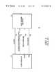
- FIG. 1illustrates a memory system including certain ones of the signals lines and buses coupling a memory controller and a conventional DDR SDRAM memory inclusive of a differential clock and address/command bus as well as bi-directional data and data strobe buses;
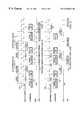
- FIG. 2illustrates the signals which might appear on the signal lines and buses shown in FIG. 1 in response to a DDR SDRAM four word burst read operation illustrating a column address strobe (“CAS”) latency of 2 ;
- CAScolumn address strobe
- FIG. 3is a corresponding illustration of the signals which might appear on the corresponding signal lines for a random row access, four word burst and same bank activate operation demonstrating the latency inherent in such an operation in conventional DDR SDRAMs;
- FIG. 4is a representative functional logic block diagram of a double data rate synchronous dynamic random access memory device in accordance with the present invention which incorporates a static random access memory cache per memory bank illustrating, for purposes of example only, a device incorporating four DRAM memory arrays and their corresponding SRAM row caches;
- FIG. 5illustrates the signals which might appear on the differential clock line, command, data strobe and data buses between a memory controller and a memory device in accordance with the present invention illustrating a series of pipelined random burst read operations with a bit length (“BL”) of 8 ;
- FIG. 6is a corresponding illustration of the same signals for a memory device in accordance with the present invention in a “no write transfer” mode of operation.
- JEDECJoint Electron Device Engineering Step
- the DDR SDRAM memory 14includes clock inputs 16 that synchronizes all data transfers and includes a data bus 22 whereby data may be moved bi-directionally between the controller 12 and DDR SDRAM 14 .
- the bi-directional data strobe line 20is unique to DDR SDRAMs and the transfers of data on the data bus 22 are synchronized to the signals on the data strobe line 20 rather than the clock signal on clock line 16 .
- the purpose of the data strobe line 20is to account for the propagation delays of the signals between the controller 12 and the memory 14 so that the effect of those delays can be nullified which then improves the ability to clock the memory 14 at higher speeds.
- a timing diagram of a conventional DDR SDRAM 14 burst readis shown with a CAS latency of 2.
- CAS latencyis defined as the delay from the time a read command is issued to time when the first read data is presented on the data bus 22 .
- the clocking signals on the clock lines 16are a differential clock, that is, the clock signal and its inversion are both sent to the memory 14 to enable a more precise control of the clock timing.
- the point at which the clock signals cross overis where the clock occurs, and in the example shown, a read command is placed on the address/command bus 18 along with the column address which specifies that portion of the memory 14 to be accessed.
- the data strobe line 20is asserted, (which has not been activated prior to the read command) and goes to a stable value which, in the example shown, is a logic low.
- the data on the data bus 22is then clocked on the rising and falling edges of the data strobe signal on the data strobe line 20 .
- the data bus 22 and the data strobe line 20become high Z, or deactivated so that another memory 14 can access the data bus 22 .
- the amount of time from when the read command is issued until the first data strobe signal occursis roughly two clock cycles from the read command, resulting in a CAS latency of 2, which, in a DDR SDRAM 14 is a programmable feature.
- an activate commandenables the DDR SDRAM 14 and a row address is sent to the row decoder at the same time to select one of the locations in the DDR SDRAM 14 . Then a delay occurs (no operation “NOP”), from the initial activate command until the read command occurs to allow the data to be accessed from the DDR SDRAM 14 and placed into the sense amplifiers.
- NOPno operation
- the read commandis issued, the corresponding column address is specified so the address comes in, goes to the column decoder, column decoder then selects a pair of the locations in the DDR SDRAM to be output.
- a four-word burstis illustrated so that just four data words will be transferred on the data bus 22 .
- the memory dataIn a conventional DDR SDRAM, the memory data must be held in the sense amplifiers (where the data then resides) while data is being bursted to the data bus 22 and, as a consequence, the precharge command cannot be issued until the last data word enters the data pipeline. Then a delay from the precharge command (“NOP”) must occur until the next bank activate command can be issued thereby defining the precharge time.
- NOPprecharge command
- the overall latencythen consists of the row access time, the column access time and the precharge time which, in a conventional DDR SDRAM cannot be completely hidden. In other words, the latency time is much longer that the time actually required to transfer the two (or four) data words. Consequently, a conventional DDR SDRAM 14 is not particularly efficient in this regard.
- FIG. 4a functional logic block diagram of a double data rate synchronous dynamic random access memory device 100 in accordance with the present invention is shown which incorporates a static random access memory cache 120 per memory bank 114 .
- a device 100 incorporating four DRAM memory arrays 114 1 - 114 4 and their corresponding SRAM row caches 120 1 - 120 4is shown.
- the memory device 100may include an address bus 102 (A) and bank select lines 104 (BA0,1) corresponding to the address portion of the address/command bus 18 utilized in conjunction with a conventional DDR SDRAM 14 as previously described. Moreover, the memory device 100 may further include a bi-directional data strobe line 106 (“DQS”) and data bus 108 (“DQ”) for interfacing with a controller (not shown).
- Aaddress bus 102
- BA0,1bank select lines 104
- DQSdata strobe line 106
- DQdata bus 108
- the address bus 102 and bank select lines 104are input to an address buffer 110 which supplies output address signals to a common row decoder 112 and individual column decoders 116 1 - 116 4 corresponding to each of the memory banks 114 1 - 114 4 .
- a sense amplifier 118 1 - 118 4 and SRAM row cache 120 1 - 120 4couples the column decoders 116 1 - 116 4 to its corresponding memory bank 114 1 - 114 4 .
- a data latch 122 1 - 122 4respectively couples the data I/O buffers and multiplexer (“mux”) 124 (coupled to the data strobe line 106 and data bus 108 ) to the sense amplifiers 118 1 - 118 4 and receives data from the respective SRAM row caches 120 1 - 120 4 .
- an SRAM row cache 120is in the path from the sense amplifiers 118 to the associated data latch 122 and then from there the data is moved to the data I/O buffers 124 .
- Thishas the effect of buffering the data from the DRAM memory banks 114 allowing faster access to the data randomly within the cache 120 . It also has the effect of allowing the data that's in the sense amplifiers 118 to be stored back into the DRAM memory banks 114 concurrently with the accessing of data from the cache 120 .
- All writesgo from the input pins of the memory device 100 to the data latch 122 , to the sense amplifiers 118 , and then basically the data is stored into the DRAM memory banks 114 from there.
- Logic on the chipdetermines the data that is currently being held in the SRAM cache 120 and, if the data that is in the sense amplifiers 118 matches that in the corresponding cache 120 , then that data is also written in parallel into the cache 120 over the normal read path. This then has the effect of allowing a faster random access time on reads, hidden precharge time, hidden bank activation timing, and hidden refresh timing as will be more fully described hereinafter.
- the row address input from the address buffer 110is decoded by the row decoder 112 to select the DRAM row of the bank 114 1 - 114 4 specified by the bank select signal BA0,1 on bank select lines 104 .
- the DRAM row datais latched into the sense amplifier 118 of the specified memory bank 114 .
- the column addressis transferred from the address buffer 110 to the corresponding column decoder 116 1 - 116 4.
- the read commandopens the selected SRAM row cache 120 and the sense amplifier 118 contents are loaded into the cache 120 in parallel.
- the column decoder 116selects the specified starting address to the data latches 122 .
- the read commandthen loads a number of words from the row cache 120 to the data latch 122 twice as wide as the output data bus 108 (for example, 32 bits read from the cache 120 for a 16-bit output data bus 108 ).
- This double wide transferprovides the data bandwidth to support the requirements of the DDR SDRAM data I/O buffers 124 and logic.
- the memory device 100 of the present inventionincludes differential clock signals 130 which are the same as that utilized in conjunction with a conventional DDR SDRAM 14 (FIG. 1) but is shown here as a single signal with rising and falling edges for sake of clarity.
- the burst address counter(not shown) built into the column decoder 116 1 - 116 4 increments every clock cycle transferring two words to the corresponding data latch 122 1 - 122 4 .
- Data wordsare transferred to the data I/O buffers 124 on both the clock rising and falling edges to double the burst data rate.
- the sense amplifier 118 1 - 118 4 datais latched into the associated SRAM row cache 120 1 - 120 4 one cycle after the read command is issued. If the read is performed with auto-precharge, the sense amplifier 1181 - 1184 data is automatically restored to the DRAM bank 114 1 - 114 4 row one cycle after the read and the DRAM memory bank 114 1 - 114 4 is ready for further bank activation after the precharge time (t RP ). Once the DRAM bank 114 1 - 114 4 is precharged, the memory device 100 can perform either another memory bank 114 activation to fetch another row to the sense amplifiers 118 or an auto-refresh command can be issued to refresh the DRAM array memory banks 114 .
- the presence of the SRAM row cache 120 1 - 120 4 associated with each of the memory banks 114 1 - 114 4respectively allows the latency of precharge, bank activation or refresh to be hidden during burst reads from the SRAM cache 118 . This improves the bus efficiency of the memory device 100 under random access and refresh conditions.
- Another important feature of the memory device 100 of the present inventionis observed during write operations.
- datais latched into the data latch 122 on the rising and falling edges of the clock (i.e. double data rate).
- Datais written into the row of data already stored in the sense amplifiers 118 1 - 118 4 following the falling edge.
- the data word transferred to the sense amplifiers 118 1 - 118 4is twice as large as the data I/O buffers 124 (for example, 32-bit wide write for 16-bit data I/O buffers) to support the write bandwidth of the memory device 100 .
- a bank activate commandinitiates a row access (designated t RCD ), and a CAS latency from the read command (Read Auto-Precharge “AP”) corresponds to a column access.
- the memory device 100 of the present inventionprovides the capability to enable an early auto-precharge operation of the DRAM memory banks 114 1 - 114 4 starting one differential clock cycle after a read command is issued, during which time the data from the sense amplifiers 118 1 - 1184 is loaded to the associated SRAM row caches 120 1 - 120 4 . Once the data is latched into the row cache 120 , the precharge of the associated DRAM memory bank 114 can begin.
- the precharge operationcan occur while the data is propagating to the memory device 100 output and, unlike a conventional DDR SDRAM 14 (FIG. 1 ), the precharge operation is complete (i.e. “hidden”) during the output of the first two data words.
- the data transfermay be observed to occur with the transfer of the first data word on the rising edge following a column access latency, the second data word on the following falling edge and so forth.
- the memory device 100 of the present inventionis also operative to effectively hide the row access time latency with read burst lengths of, for example, eight.
- Thiscan be visualized as when a row of memory is activated within the same memory bank 114 by inputting another row address, activating the row decoder 112 , fetching another location within the same memory bank 114 and moving that data to the sense amplifier 118 while the burst of eight data words is being output from the associated SRAM row cache 120 .
- Thisthen allows for the concurrent fetching of another row of data into the sense amplifiers 118 and having that data ready prior to the completion of the bursting of eight data words from the associated SRAM row cache 120 to minimize the latency from one random access to another by reducing it to just the column access latency. In effect then, this serves to eliminate the precharge and row access latencies inherent in conventional DDR SDRAMs 14 (FIG. 1 ).
- the memory device 100may also have an optional “no write transfer” mode of operation.
- this modethe row data in the sense amplifiers 118 1 - 118 4 is not written into the associated row cache 120 1 - 120 4 on the write command. This allows data to be written only to the DRAM memory banks 114 1 - 114 4 during a write “miss” (i.e. a write to a different row address from that currently held in the corresponding cache 120 1 - 120 4 ).
- a comparator (not shown) on the memory device 100automatically causes the appropriate cache 120 1 - 120 4 to be written at the same time as the sense amplifier 118 1 - 118 4 when a write “hit” (i.e. a write to the same row address as that currently held in the corresponding cache 120 1 - 120 4 ) is detected.
- the “no write transfer” featureallows a read “hit” to occur one cycle after the end of the write burst and the write data can be automatically restored to the DRAM memory bank 114 1 - 114 4 in parallel with this read burst if a write auto-precharge is executed.
- This “no write transfer” mode of operationthen effectively eliminates a portion of page miss latency on the initial opening of the write page and a complete page miss latency during a return to the original read page that follows a write or write burst. This feature further improves bus efficiency on write cycles.
- the initiation of the memory device 100 accessbegins in a manner similar to that shown in the preceding FIG. 5 with a bank activate command, a delay due to a row access, and then a read auto-precharge command.
- the hidden precharge operationcan occur one cycle after the read command, with a burst of four data words from the SRAM cache 120 1 - 120 4 .
- a pageis enabled to allow writes to it.
- the precharge operationbegins.
- the precharge timeis then met, and then another bank activate command with a row address is specified, which in the example shown, is a write row address with auto-precharge after the row-to-column delay is met.
- the datais now in the sense amplifiers 118 and it can be modified by the write cycle.
- the write auto-precharge commandmay be issued by the associated controller (not shown) a cycle before the data.
- the first data wordis generated on a rising edge of the differential clock signal, the second data word on the falling edge and so forth and by completing an early precharge operation and an early memory bank 114 activation, the normal latency of a conventional DDR SDRAM 14 (FIG.
- the write burstbasically occurs as it would in a conventional DDR SDRAM 14 although if the next request is another read request to the same data that was previously held in the SRAM row cache 120 , (writes to the memory device 100 are to the DRAM sense amplifiers 118 and reads are from the SRAM row caches 120 ) the data is still held from the previous read command in the SRAM row cache 120 in the “no-write transfer” mode of operation.
- the read commandcan be initiated while the write data is being input to the memory device 100 allowing the CAS latency to occur with minimum delay because there is no need to wait for the data in the memory banks 114 to be precharged and the write data precharge can occur later.
- D 4the final data word (“D 4 ”) must be written to the sense amplifiers during the following cycle before the auto-precharge can occur.
- a number of wait stateswould have to be entered until the write precharge operation has been completed, followed by another random read, (involving issuing bank activate and read commands) before the next data could be made available.
- the write precharge timemay be effectively “hidden” and the need for another row activate command eliminated due to the fact that the data was held in the SRAM row cache 120 during this transfer thereby eliminating all of the conventional latency inherent in a read command following a write.
- two sources of conventional latencyhave been eliminated, one on the write cycle following a read, and another on a read “hit” that follows a write.
- the effective bandwidthis t RC +4*t CLKmax .
- typical DDR SDRAM 14FIG. 1 with a write setup of (t RP +tR CD +1 CLK) and read setup of (1 CLK+t RC ) only twenty data transfers for 56 clock edges can be achieved resulting in a data bus 22 efficiency of only 36%.
- a memory device 100 in accordance with the present invention implementing a “no write transfer” mode of operationthen further improves data bus efficiency from 36% to 83%.
Landscapes
- Dram (AREA)
Abstract
Description
Claims (18)
Priority Applications (1)
| Application Number | Priority Date | Filing Date | Title |
|---|---|---|---|
| US09/236,804US6330636B1 (en) | 1999-01-29 | 1999-01-29 | Double data rate synchronous dynamic random access memory device incorporating a static RAM cache per memory bank |
Applications Claiming Priority (1)
| Application Number | Priority Date | Filing Date | Title |
|---|---|---|---|
| US09/236,804US6330636B1 (en) | 1999-01-29 | 1999-01-29 | Double data rate synchronous dynamic random access memory device incorporating a static RAM cache per memory bank |
Publications (1)
| Publication Number | Publication Date |
|---|---|
| US6330636B1true US6330636B1 (en) | 2001-12-11 |
Family
ID=22891043
Family Applications (1)
| Application Number | Title | Priority Date | Filing Date |
|---|---|---|---|
| US09/236,804Expired - LifetimeUS6330636B1 (en) | 1999-01-29 | 1999-01-29 | Double data rate synchronous dynamic random access memory device incorporating a static RAM cache per memory bank |
Country Status (1)
| Country | Link |
|---|---|
| US (1) | US6330636B1 (en) |
Cited By (39)
| Publication number | Priority date | Publication date | Assignee | Title |
|---|---|---|---|---|
| US6415374B1 (en)* | 2000-03-16 | 2002-07-02 | Mosel Vitelic, Inc. | System and method for supporting sequential burst counts in double data rate (DDR) synchronous dynamic random access memories (SDRAM) |
| US6546461B1 (en) | 2000-11-22 | 2003-04-08 | Integrated Device Technology, Inc. | Multi-port cache memory devices and FIFO memory devices having multi-port cache memory devices therein |
| US20030145158A1 (en)* | 2002-01-31 | 2003-07-31 | Hsu Louis L. | Embedded DRAM system having wide data bandwidth and data transfer data protocol |
| WO2003065376A1 (en)* | 2002-01-28 | 2003-08-07 | Intel Corporation | Apparatus and method for encoding auto-precharge |
| US20030206475A1 (en)* | 2001-08-23 | 2003-11-06 | Jiann-Jeng Duh | FIFO memory devices that support all combinations of DDR and SDR read and write modes |
| US20030236958A1 (en)* | 2002-06-20 | 2003-12-25 | Mobley Kenneth J. | Method and circuit for increasing the memory access speed of an enhanced synchronous SDRAM |
| US20040085850A1 (en)* | 2002-10-31 | 2004-05-06 | Kabushiki Kaisha Toshiba | Semiconductor memory capable of performing high-speed processing |
| US6757784B2 (en)* | 2001-09-28 | 2004-06-29 | Intel Corporation | Hiding refresh of memory and refresh-hidden memory |
| US6763416B1 (en)* | 1999-07-29 | 2004-07-13 | Micron Technology, Inc. | Capturing read data |
| US20050018514A1 (en)* | 2001-08-23 | 2005-01-27 | Knaack Roland T. | Integrated DDR/SDR flow control managers that support multiple queues and mux, demux and broadcast operating modes |
| US20050071541A1 (en)* | 2003-09-30 | 2005-03-31 | Osborne Randy B. | Method and apparatus for implicit DRAM precharge |
| WO2005038811A1 (en)* | 2003-09-30 | 2005-04-28 | Infineon Technologies Ag | Memory arrangement comprising a plurality of ram modules |
| US20050105349A1 (en)* | 2003-11-04 | 2005-05-19 | Dahlberg James A. | Programmable data strobe offset with DLL for double data rate (DDR) RAM memory |
| US20050111275A1 (en)* | 2003-11-26 | 2005-05-26 | Oliver Kiehl | Cost efficient row cache for DRAMs |
| US20050146975A1 (en)* | 2003-12-30 | 2005-07-07 | Halbert John B. | Method and apparatus for multiple row caches per bank |
| US20050146974A1 (en)* | 2003-12-30 | 2005-07-07 | Halbert John B. | Method and apparatus for multiple row caches per bank |
| US20050162957A1 (en)* | 2004-01-28 | 2005-07-28 | Infineon Technologies North America Corp. | Memory device with non-variable write latency |
| US20050278474A1 (en)* | 2004-05-26 | 2005-12-15 | Perersen Ryan M | Method of increasing DDR memory bandwidth in DDR SDRAM modules |
| US7042792B2 (en) | 2004-01-14 | 2006-05-09 | Integrated Device Technology, Inc. | Multi-port memory cells for use in FIFO applications that support data transfers between cache and supplemental memory arrays |
| US7120075B1 (en) | 2003-08-18 | 2006-10-10 | Integrated Device Technology, Inc. | Multi-FIFO integrated circuit devices that support multi-queue operating modes with enhanced write path and read path queue switching |
| US7146454B1 (en)* | 2002-04-16 | 2006-12-05 | Cypress Semiconductor Corporation | Hiding refresh in 1T-SRAM architecture |
| US7177379B1 (en) | 2003-04-29 | 2007-02-13 | Advanced Micro Devices, Inc. | DDR on-the-fly synchronization |
| US20080239843A1 (en)* | 2007-03-30 | 2008-10-02 | Fujitisu Limited | Interface circuit, memory interface system, and data reception method |
| US20120127809A1 (en)* | 2010-11-23 | 2012-05-24 | Hynix Semiconductor Inc. | Precharge signal generation circuit of semiconductor memory apparatus |
| US8688892B2 (en) | 2004-05-26 | 2014-04-01 | OCZ Storage Solutions Inc. | System and method for increasing DDR memory bandwidth in DDR SDRAM modules |
| TWI453756B (en)* | 2007-04-10 | 2014-09-21 | Samsung Electronics Co Ltd | System and device with error detection/correction process and method outputting data |
| US20150023119A1 (en)* | 2013-07-16 | 2015-01-22 | SK Hynix Inc. | Semiconductor device and semiconductor system having the same |
| US20150049570A1 (en)* | 2013-08-16 | 2015-02-19 | Sung-Hyun Lee | Memory device, memory system including the same, operating method thereof |
| US20150302907A1 (en)* | 2014-04-16 | 2015-10-22 | Micron Technology, Inc. | Apparatuses and methods for implementing masked write commands |
| US9281045B1 (en) | 2014-12-16 | 2016-03-08 | Globalfoundries Inc. | Refresh hidden eDRAM memory |
| RU2625074C2 (en)* | 2013-01-29 | 2017-07-17 | Сони Компьютер Энтертейнмент Эмерике Ллк | Methods and hardware designed to conceal delay in multiplayer online games |
| WO2017189065A1 (en)* | 2016-04-28 | 2017-11-02 | Everspin Technologies, Inc. | Delayed write-back in memory |
| WO2018063588A1 (en)* | 2016-09-28 | 2018-04-05 | Intel Corporation | Shared command address (c/a) bus for multiple memory channels |
| US20180096729A1 (en)* | 2001-12-19 | 2018-04-05 | Toshiba Memory Corporation | Semiconductor integrated circuit adapted to output pass/fail results of internal operations |
| CN108763106A (en)* | 2018-05-31 | 2018-11-06 | 西安微电子技术研究所 | A kind of Cache implementation methods based on interleaved |
| CN110389913A (en)* | 2019-07-26 | 2019-10-29 | 南京凯鼎电子科技有限公司 | It is a kind of for improving the feedback device and method of DDR bus utilization |
| KR20190141235A (en)* | 2017-04-27 | 2019-12-23 | 에버스핀 테크놀러지스, 인크. | Post-Delay Post-Memory in Memory with Calibration Support |
| CN112015693A (en)* | 2020-07-31 | 2020-12-01 | 成都中安频谱科技有限公司 | Method and system for realizing large-scale DDC based on FPGA |
| US11127443B2 (en)* | 2020-01-08 | 2021-09-21 | Micron Technology, Inc. | Timing chains for accessing memory cells |
Citations (48)
| Publication number | Priority date | Publication date | Assignee | Title |
|---|---|---|---|---|
| JPS60258792A (en) | 1984-06-04 | 1985-12-20 | Toshiba Corp | Dynamic RAM |
| US4577293A (en) | 1984-06-01 | 1986-03-18 | International Business Machines Corporation | Distributed, on-chip cache |
| US4608666A (en) | 1983-06-24 | 1986-08-26 | Tokyo Shibaura Denki Kabushiki Kaisha | Semiconductor memory |
| US4725945A (en) | 1984-09-18 | 1988-02-16 | International Business Machines Corp. | Distributed cache in dynamic rams |
| JPS6381692A (en) | 1986-09-26 | 1988-04-12 | Hitachi Ltd | semiconductor storage device |
| US4794559A (en) | 1984-07-05 | 1988-12-27 | American Telephone And Telegraph Company, At&T Bell Laboratories | Content addressable semiconductor memory arrays |
| JPH01159891A (en) | 1987-12-17 | 1989-06-22 | Mitsubishi Electric Corp | Semiconductor memory |
| US4870622A (en) | 1988-06-24 | 1989-09-26 | Advanced Micro Devices, Inc. | DRAM controller cache |
| US4894770A (en) | 1987-06-01 | 1990-01-16 | Massachusetts Institute Of Technology | Set associative memory |
| US4926385A (en) | 1987-08-05 | 1990-05-15 | Mitsubishi Denki Kabushiki Kaisha | Semiconductor memory device with cache memory addressable by block within each column |
| US4943944A (en) | 1987-11-25 | 1990-07-24 | Kabushiki Kaisha Toshiba | Semiconductor memory using dynamic ram cells |
| US5025421A (en) | 1989-01-09 | 1991-06-18 | Cho Gyung Y | Single port dual RAM |
| DE4118847A1 (en) | 1990-06-08 | 1991-12-12 | Toshiba Kawasaki Kk | Semiconductor DRAM with matrix of cells coupled to driver leads - has read=out amplifiers connected and selectable by column address |
| US5111386A (en) | 1987-12-02 | 1992-05-05 | Mitsubishi Denki Kabushiki Kaisha | Cache contained type semiconductor memory device and operating method therefor |
| US5134616A (en) | 1990-02-13 | 1992-07-28 | International Business Machines Corporation | Dynamic ram with on-chip ecc and optimized bit and word redundancy |
| US5148396A (en) | 1989-02-27 | 1992-09-15 | Nec Corporation | Semiconductor integrated circuit memory enabling memory write masking |
| US5179687A (en) | 1987-09-26 | 1993-01-12 | Mitsubishi Denki Kabushiki Kaisha | Semiconductor memory device containing a cache and an operation method thereof |
| US5184320A (en) | 1988-02-12 | 1993-02-02 | Texas Instruments Incorporated | Cached random access memory device and system |
| US5184325A (en) | 1989-03-10 | 1993-02-02 | Board Of Regents, The University Of Texas System | Dynamic associative memory with logic-in-refresh |
| US5214610A (en) | 1989-09-22 | 1993-05-25 | Texas Instruments Incorporated | Memory with selective address transition detection for cache operation |
| US5226139A (en) | 1990-01-16 | 1993-07-06 | Mitsubishi Denki Kabushiki Kaisha | Semiconductor memory device with a built-in cache memory and operating method thereof |
| US5226147A (en) | 1987-11-06 | 1993-07-06 | Mitsubishi Denki Kabushiki Kaisha | Semiconductor memory device for simple cache system |
| US5226009A (en) | 1990-03-30 | 1993-07-06 | Mitsubishi Denki Kabushiki Kaisha | Semiconductor memory device supporting cache and method of driving the same |
| US5249282A (en) | 1990-11-21 | 1993-09-28 | Benchmarq Microelectronics, Inc. | Integrated cache memory system with primary and secondary cache memories |
| US5305280A (en) | 1991-04-04 | 1994-04-19 | Mitsubishi Denki Kabushiki Kaisha | Semiconductor memory device having on the same chip a plurality of memory circuits among which data transfer is performed to each other and an operating method thereof |
| US5329489A (en) | 1988-03-31 | 1994-07-12 | Texas Instruments Incorporated | DRAM having exclusively enabled column buffer blocks |
| US5359722A (en) | 1990-07-23 | 1994-10-25 | International Business Machines Corporation | Method for shortening memory fetch time relative to memory store time and controlling recovery in a DRAM |
| US5381370A (en) | 1993-08-24 | 1995-01-10 | Cypress Semiconductor Corporation | Memory with minimized redundancy access delay |
| US5390308A (en) | 1992-04-15 | 1995-02-14 | Rambus, Inc. | Method and apparatus for address mapping of dynamic random access memory |
| US5404338A (en) | 1993-01-29 | 1995-04-04 | Mitsubishi Denki Kabushiki Kaisha | Synchronous type semiconductor memory device operating in synchronization with an external clock signal |
| US5421000A (en) | 1989-04-25 | 1995-05-30 | International Business Machines Corp. | Memory subsystem having a static row memory and a dynamic RAM |
| US5471601A (en) | 1992-06-17 | 1995-11-28 | Intel Corporation | Memory device and method for avoiding live lock of a DRAM with cache |
| US5539696A (en) | 1994-01-31 | 1996-07-23 | Patel; Vipul C. | Method and apparatus for writing data in a synchronous memory having column independent sections and a method and apparatus for performing write mask operations |
| US5568427A (en) | 1994-07-14 | 1996-10-22 | Fujitsu Limited | Memory and method of reading out of the memory |
| US5600605A (en) | 1995-06-07 | 1997-02-04 | Micron Technology, Inc. | Auto-activate on synchronous dynamic random access memory |
| US5627791A (en) | 1996-02-16 | 1997-05-06 | Micron Technology, Inc. | Multiple bank memory with auto refresh to specified bank |
| US5636173A (en) | 1995-06-07 | 1997-06-03 | Micron Technology, Inc. | Auto-precharge during bank selection |
| US5655105A (en) | 1995-06-30 | 1997-08-05 | Micron Technology, Inc. | Method and apparatus for multiple latency synchronous pipelined dynamic random access memory |
| US5666321A (en) | 1995-09-01 | 1997-09-09 | Micron Technology, Inc. | Synchronous DRAM memory with asynchronous column decode |
| US5673233A (en) | 1996-02-16 | 1997-09-30 | Micron Technology, Inc. | Synchronous memory allowing early read command in write to read transitions |
| US5787457A (en)* | 1996-10-18 | 1998-07-28 | International Business Machines Corporation | Cached synchronous DRAM architecture allowing concurrent DRAM operations |
| US5875134A (en)* | 1995-08-30 | 1999-02-23 | Micron Technology, Inc. | Data communication for memory |
| US6044032A (en)* | 1998-12-03 | 2000-03-28 | Micron Technology, Inc. | Addressing scheme for a double data rate SDRAM |
| US6044026A (en)* | 1998-06-05 | 2000-03-28 | Micron Technology, Inc. | Trap and delay pulse generator for a high speed clock |
| US6067260A (en)* | 1998-06-22 | 2000-05-23 | Mitsubishi Denki Kabushiki Kaisha | Synchronous semiconductor memory device having redundant circuit of high repair efficiency and allowing high speed access |
| US6081477A (en)* | 1998-12-03 | 2000-06-27 | Micron Technology, Inc. | Write scheme for a double data rate SDRAM |
| US6104650A (en)* | 1999-07-09 | 2000-08-15 | Micron Technology, Inc. | Sacrifice read test mode |
| US6111807A (en)* | 1998-07-17 | 2000-08-29 | Mitsubishi Denki Kabushiki Kaisha | Synchronous semiconductor memory device allowing easy and fast text |
- 1999
- 1999-01-29USUS09/236,804patent/US6330636B1/ennot_activeExpired - Lifetime
Patent Citations (50)
| Publication number | Priority date | Publication date | Assignee | Title |
|---|---|---|---|---|
| US4608666A (en) | 1983-06-24 | 1986-08-26 | Tokyo Shibaura Denki Kabushiki Kaisha | Semiconductor memory |
| US4577293A (en) | 1984-06-01 | 1986-03-18 | International Business Machines Corporation | Distributed, on-chip cache |
| JPS60258792A (en) | 1984-06-04 | 1985-12-20 | Toshiba Corp | Dynamic RAM |
| US4794559A (en) | 1984-07-05 | 1988-12-27 | American Telephone And Telegraph Company, At&T Bell Laboratories | Content addressable semiconductor memory arrays |
| US4725945A (en) | 1984-09-18 | 1988-02-16 | International Business Machines Corp. | Distributed cache in dynamic rams |
| JPS6381692A (en) | 1986-09-26 | 1988-04-12 | Hitachi Ltd | semiconductor storage device |
| US4894770A (en) | 1987-06-01 | 1990-01-16 | Massachusetts Institute Of Technology | Set associative memory |
| US4926385A (en) | 1987-08-05 | 1990-05-15 | Mitsubishi Denki Kabushiki Kaisha | Semiconductor memory device with cache memory addressable by block within each column |
| US5179687A (en) | 1987-09-26 | 1993-01-12 | Mitsubishi Denki Kabushiki Kaisha | Semiconductor memory device containing a cache and an operation method thereof |
| US5226147A (en) | 1987-11-06 | 1993-07-06 | Mitsubishi Denki Kabushiki Kaisha | Semiconductor memory device for simple cache system |
| US5353427A (en) | 1987-11-06 | 1994-10-04 | Mitsubishi Denki Kabushiki Kaisha | Semiconductor memory device for simple cache system with selective coupling of bit line pairs |
| US4943944A (en) | 1987-11-25 | 1990-07-24 | Kabushiki Kaisha Toshiba | Semiconductor memory using dynamic ram cells |
| US5111386A (en) | 1987-12-02 | 1992-05-05 | Mitsubishi Denki Kabushiki Kaisha | Cache contained type semiconductor memory device and operating method therefor |
| JPH01159891A (en) | 1987-12-17 | 1989-06-22 | Mitsubishi Electric Corp | Semiconductor memory |
| US5184320A (en) | 1988-02-12 | 1993-02-02 | Texas Instruments Incorporated | Cached random access memory device and system |
| US5329489A (en) | 1988-03-31 | 1994-07-12 | Texas Instruments Incorporated | DRAM having exclusively enabled column buffer blocks |
| US4870622A (en) | 1988-06-24 | 1989-09-26 | Advanced Micro Devices, Inc. | DRAM controller cache |
| US5025421A (en) | 1989-01-09 | 1991-06-18 | Cho Gyung Y | Single port dual RAM |
| US5148396A (en) | 1989-02-27 | 1992-09-15 | Nec Corporation | Semiconductor integrated circuit memory enabling memory write masking |
| US5184325A (en) | 1989-03-10 | 1993-02-02 | Board Of Regents, The University Of Texas System | Dynamic associative memory with logic-in-refresh |
| US5421000A (en) | 1989-04-25 | 1995-05-30 | International Business Machines Corp. | Memory subsystem having a static row memory and a dynamic RAM |
| US5214610A (en) | 1989-09-22 | 1993-05-25 | Texas Instruments Incorporated | Memory with selective address transition detection for cache operation |
| US5226139A (en) | 1990-01-16 | 1993-07-06 | Mitsubishi Denki Kabushiki Kaisha | Semiconductor memory device with a built-in cache memory and operating method thereof |
| US5134616A (en) | 1990-02-13 | 1992-07-28 | International Business Machines Corporation | Dynamic ram with on-chip ecc and optimized bit and word redundancy |
| US5226009A (en) | 1990-03-30 | 1993-07-06 | Mitsubishi Denki Kabushiki Kaisha | Semiconductor memory device supporting cache and method of driving the same |
| DE4118847A1 (en) | 1990-06-08 | 1991-12-12 | Toshiba Kawasaki Kk | Semiconductor DRAM with matrix of cells coupled to driver leads - has read=out amplifiers connected and selectable by column address |
| US5359722A (en) | 1990-07-23 | 1994-10-25 | International Business Machines Corporation | Method for shortening memory fetch time relative to memory store time and controlling recovery in a DRAM |
| US5249282A (en) | 1990-11-21 | 1993-09-28 | Benchmarq Microelectronics, Inc. | Integrated cache memory system with primary and secondary cache memories |
| US5305280A (en) | 1991-04-04 | 1994-04-19 | Mitsubishi Denki Kabushiki Kaisha | Semiconductor memory device having on the same chip a plurality of memory circuits among which data transfer is performed to each other and an operating method thereof |
| US5390308A (en) | 1992-04-15 | 1995-02-14 | Rambus, Inc. | Method and apparatus for address mapping of dynamic random access memory |
| US5471601A (en) | 1992-06-17 | 1995-11-28 | Intel Corporation | Memory device and method for avoiding live lock of a DRAM with cache |
| US5404338A (en) | 1993-01-29 | 1995-04-04 | Mitsubishi Denki Kabushiki Kaisha | Synchronous type semiconductor memory device operating in synchronization with an external clock signal |
| US5381370A (en) | 1993-08-24 | 1995-01-10 | Cypress Semiconductor Corporation | Memory with minimized redundancy access delay |
| US5539696A (en) | 1994-01-31 | 1996-07-23 | Patel; Vipul C. | Method and apparatus for writing data in a synchronous memory having column independent sections and a method and apparatus for performing write mask operations |
| US5568427A (en) | 1994-07-14 | 1996-10-22 | Fujitsu Limited | Memory and method of reading out of the memory |
| US5636173A (en) | 1995-06-07 | 1997-06-03 | Micron Technology, Inc. | Auto-precharge during bank selection |
| US5600605A (en) | 1995-06-07 | 1997-02-04 | Micron Technology, Inc. | Auto-activate on synchronous dynamic random access memory |
| US5655105A (en) | 1995-06-30 | 1997-08-05 | Micron Technology, Inc. | Method and apparatus for multiple latency synchronous pipelined dynamic random access memory |
| US5875134A (en)* | 1995-08-30 | 1999-02-23 | Micron Technology, Inc. | Data communication for memory |
| US5986948A (en)* | 1995-08-30 | 1999-11-16 | Micron Technology, Inc. | Data communication for memory |
| US5666321A (en) | 1995-09-01 | 1997-09-09 | Micron Technology, Inc. | Synchronous DRAM memory with asynchronous column decode |
| US5627791A (en) | 1996-02-16 | 1997-05-06 | Micron Technology, Inc. | Multiple bank memory with auto refresh to specified bank |
| US5673233A (en) | 1996-02-16 | 1997-09-30 | Micron Technology, Inc. | Synchronous memory allowing early read command in write to read transitions |
| US5787457A (en)* | 1996-10-18 | 1998-07-28 | International Business Machines Corporation | Cached synchronous DRAM architecture allowing concurrent DRAM operations |
| US6044026A (en)* | 1998-06-05 | 2000-03-28 | Micron Technology, Inc. | Trap and delay pulse generator for a high speed clock |
| US6067260A (en)* | 1998-06-22 | 2000-05-23 | Mitsubishi Denki Kabushiki Kaisha | Synchronous semiconductor memory device having redundant circuit of high repair efficiency and allowing high speed access |
| US6111807A (en)* | 1998-07-17 | 2000-08-29 | Mitsubishi Denki Kabushiki Kaisha | Synchronous semiconductor memory device allowing easy and fast text |
| US6044032A (en)* | 1998-12-03 | 2000-03-28 | Micron Technology, Inc. | Addressing scheme for a double data rate SDRAM |
| US6081477A (en)* | 1998-12-03 | 2000-06-27 | Micron Technology, Inc. | Write scheme for a double data rate SDRAM |
| US6104650A (en)* | 1999-07-09 | 2000-08-15 | Micron Technology, Inc. | Sacrifice read test mode |
Non-Patent Citations (8)
| Title |
|---|
| "DM 2202 EDRAM 1Mb×4 Enchanced Dynamic RAM—Product Review," May 22, 1991, Ramtron, Colorado Springs, Colorado. |
| "DM 2202 EDRAM 1Mbx4 Enchanced Dynamic RAM-Product Review," May 22, 1991, Ramtron, Colorado Springs, Colorado. |
| Bursky, "Combination DRAM-SRAM Removes Secondary Caches", Electr. Design, vol. 40, No. 2, pp. 39-43, Jan. 23, 1992. |
| Dosaka et al., "A 100MHz 4Mb Cache DRAM with Fast Copy-back Scheme," Digest of Technical Papers, 1992 IEEE International Solid-State Circuits Conference, p. 148-149 (6/92). |
| Goodman et al. "Use of Static Column RAM as a Memory Hierarchy," 11th Annual Symposium, IEEE, 1984, pp. 167-174. |
| Niijima et al, "QRAM-Quick Access Memory System", IEEE International Conference, pp. 417-420, Sep. 17, 1990. |
| Ohta et al., "A 1 MB DRAM with 33 MHz Serial I/O Ports" Digest of Technical Papers, 1986 IEEE, pp. 274-275 (1986). |
| Sartore, "New Generation of Fast Enhanced DRAMS Replace Static RAM Caches in High-end PC Work Station" 1991. |
Cited By (84)
| Publication number | Priority date | Publication date | Assignee | Title |
|---|---|---|---|---|
| US20110047312A1 (en)* | 1999-07-29 | 2011-02-24 | Micron Technology, Inc. | Capturing read data |
| US6763416B1 (en)* | 1999-07-29 | 2004-07-13 | Micron Technology, Inc. | Capturing read data |
| US7822904B2 (en)* | 1999-07-29 | 2010-10-26 | Micron Technology, Inc. | Capturing read data |
| US8065461B2 (en)* | 1999-07-29 | 2011-11-22 | Micron Technology, Inc. | Capturing read data |
| US20040210702A1 (en)* | 1999-07-29 | 2004-10-21 | Laberge Paul A. | Capturing read data |
| US6415374B1 (en)* | 2000-03-16 | 2002-07-02 | Mosel Vitelic, Inc. | System and method for supporting sequential burst counts in double data rate (DDR) synchronous dynamic random access memories (SDRAM) |
| US6546461B1 (en) | 2000-11-22 | 2003-04-08 | Integrated Device Technology, Inc. | Multi-port cache memory devices and FIFO memory devices having multi-port cache memory devices therein |
| US20040193805A1 (en)* | 2000-11-22 | 2004-09-30 | Mario Au | Fifo memory devices having multi-port cache and extended capacity memory devices therein with retransmit capability |
| US6754777B1 (en) | 2000-11-22 | 2004-06-22 | Integrated Device Technology, Inc. | FIFO memory devices and methods of operating FIFO memory devices having multi-port cache memory devices therein |
| US6874064B2 (en) | 2000-11-22 | 2005-03-29 | Integrated Device Technology, Inc. | FIFO memory devices having multi-port cache and extended capacity memory devices therein with retransmit capability |
| US20050041450A1 (en)* | 2001-08-23 | 2005-02-24 | Jiann-Jeng Duh | FIFO memory devices having write and read control circuits that support x4N, x2N and xN data widths during DDR and SDR modes of operation |
| US7158440B2 (en) | 2001-08-23 | 2007-01-02 | Integrated Device Technology, Inc. | FIFO memory devices having write and read control circuits that support x4N, x2N and xN data widths during DDR and SDR modes of operation |
| US20050018514A1 (en)* | 2001-08-23 | 2005-01-27 | Knaack Roland T. | Integrated DDR/SDR flow control managers that support multiple queues and mux, demux and broadcast operating modes |
| US6778454B2 (en) | 2001-08-23 | 2004-08-17 | Integrated Device Technology, Inc. | FIFO memory devices that support all combinations of DDR and SDR read and write modes |
| US6795360B2 (en) | 2001-08-23 | 2004-09-21 | Integrated Device Technology, Inc. | Fifo memory devices that support all four combinations of DDR or SDR write modes with DDR or SDR read modes |
| US7082071B2 (en) | 2001-08-23 | 2006-07-25 | Integrated Device Technology, Inc. | Integrated DDR/SDR flow control managers that support multiple queues and MUX, DEMUX and broadcast operating modes |
| US20030206475A1 (en)* | 2001-08-23 | 2003-11-06 | Jiann-Jeng Duh | FIFO memory devices that support all combinations of DDR and SDR read and write modes |
| US6757784B2 (en)* | 2001-09-28 | 2004-06-29 | Intel Corporation | Hiding refresh of memory and refresh-hidden memory |
| US20050097276A1 (en)* | 2001-09-28 | 2005-05-05 | Lu Shih-Lien L. | Hiding refresh of memory and refresh-hidden memory |
| US11295823B2 (en) | 2001-12-19 | 2022-04-05 | Kioxia Corporation | Semiconductor integrated circuit adapted to output pass/fail results of internal operations |
| US10741266B2 (en) | 2001-12-19 | 2020-08-11 | Toshiba Memory Corporation | Semiconductor integrated circuit adapted to output pass/fail results of internal operations |
| US10410731B2 (en)* | 2001-12-19 | 2019-09-10 | Toshiba Memory Corporation | Semiconductor integrated circuit adapted to output pass/fail results of internal operations |
| US20180096729A1 (en)* | 2001-12-19 | 2018-04-05 | Toshiba Memory Corporation | Semiconductor integrated circuit adapted to output pass/fail results of internal operations |
| CN1751358B (en)* | 2002-01-28 | 2010-11-17 | 英特尔公司 | Apparatus and method for encoding automatic pre-charging |
| US6829184B2 (en) | 2002-01-28 | 2004-12-07 | Intel Corporation | Apparatus and method for encoding auto-precharge |
| WO2003065376A1 (en)* | 2002-01-28 | 2003-08-07 | Intel Corporation | Apparatus and method for encoding auto-precharge |
| US6775736B2 (en)* | 2002-01-31 | 2004-08-10 | International Business Machines Corporation | Embedded DRAM system having wide data bandwidth and data transfer data protocol |
| US20030145158A1 (en)* | 2002-01-31 | 2003-07-31 | Hsu Louis L. | Embedded DRAM system having wide data bandwidth and data transfer data protocol |
| US7146454B1 (en)* | 2002-04-16 | 2006-12-05 | Cypress Semiconductor Corporation | Hiding refresh in 1T-SRAM architecture |
| US20030236958A1 (en)* | 2002-06-20 | 2003-12-25 | Mobley Kenneth J. | Method and circuit for increasing the memory access speed of an enhanced synchronous SDRAM |
| US6813679B2 (en) | 2002-06-20 | 2004-11-02 | Purple Mountain Server Llc | Method and circuit for increasing the memory access speed of an enhanced synchronous SDRAM |
| US7533231B1 (en) | 2002-06-20 | 2009-05-12 | Mobley Kenneth J | Method and circuit for increasing the memory access speed of an enhanced synchronous memory |
| EP1416494A3 (en)* | 2002-10-31 | 2004-12-29 | Kabushiki Kaisha Toshiba | Semiconductor memory capable of performing high-speed processing |
| US20040085850A1 (en)* | 2002-10-31 | 2004-05-06 | Kabushiki Kaisha Toshiba | Semiconductor memory capable of performing high-speed processing |
| US7177379B1 (en) | 2003-04-29 | 2007-02-13 | Advanced Micro Devices, Inc. | DDR on-the-fly synchronization |
| US7120075B1 (en) | 2003-08-18 | 2006-10-10 | Integrated Device Technology, Inc. | Multi-FIFO integrated circuit devices that support multi-queue operating modes with enhanced write path and read path queue switching |
| US7167946B2 (en)* | 2003-09-30 | 2007-01-23 | Intel Corporation | Method and apparatus for implicit DRAM precharge |
| US20060250881A1 (en)* | 2003-09-30 | 2006-11-09 | Helmut Kandolf | Memory arrangement having a plurality of RAM chips |
| WO2005038811A1 (en)* | 2003-09-30 | 2005-04-28 | Infineon Technologies Ag | Memory arrangement comprising a plurality of ram modules |
| US20050071541A1 (en)* | 2003-09-30 | 2005-03-31 | Osborne Randy B. | Method and apparatus for implicit DRAM precharge |
| US7362650B2 (en) | 2003-09-30 | 2008-04-22 | Infineon Technologies Ag | Memory arrangement having a plurality of RAM chips |
| US6940768B2 (en) | 2003-11-04 | 2005-09-06 | Agere Systems Inc. | Programmable data strobe offset with DLL for double data rate (DDR) RAM memory |
| US20050105349A1 (en)* | 2003-11-04 | 2005-05-19 | Dahlberg James A. | Programmable data strobe offset with DLL for double data rate (DDR) RAM memory |
| US20050111275A1 (en)* | 2003-11-26 | 2005-05-26 | Oliver Kiehl | Cost efficient row cache for DRAMs |
| US7215595B2 (en) | 2003-11-26 | 2007-05-08 | Infineon Technologies Ag | Memory device and method using a sense amplifier as a cache |
| US20050146974A1 (en)* | 2003-12-30 | 2005-07-07 | Halbert John B. | Method and apparatus for multiple row caches per bank |
| US20050146975A1 (en)* | 2003-12-30 | 2005-07-07 | Halbert John B. | Method and apparatus for multiple row caches per bank |
| KR100850067B1 (en) | 2003-12-30 | 2008-08-04 | 인텔 코오퍼레이션 | Method and apparatus for multiple row caches per bank |
| US7050351B2 (en) | 2003-12-30 | 2006-05-23 | Intel Corporation | Method and apparatus for multiple row caches per bank |
| WO2005066967A1 (en)* | 2003-12-30 | 2005-07-21 | Intel Corporation | Method and apparatus for multiple row caches per bank |
| US6990036B2 (en) | 2003-12-30 | 2006-01-24 | Intel Corporation | Method and apparatus for multiple row caches per bank |
| US7042792B2 (en) | 2004-01-14 | 2006-05-09 | Integrated Device Technology, Inc. | Multi-port memory cells for use in FIFO applications that support data transfers between cache and supplemental memory arrays |
| US7042777B2 (en) | 2004-01-28 | 2006-05-09 | Infineon Technologies Ag | Memory device with non-variable write latency |
| US20050162957A1 (en)* | 2004-01-28 | 2005-07-28 | Infineon Technologies North America Corp. | Memory device with non-variable write latency |
| US20050278474A1 (en)* | 2004-05-26 | 2005-12-15 | Perersen Ryan M | Method of increasing DDR memory bandwidth in DDR SDRAM modules |
| US8151030B2 (en)* | 2004-05-26 | 2012-04-03 | Ocz Technology Group, Inc. | Method of increasing DDR memory bandwidth in DDR SDRAM modules |
| US8688892B2 (en) | 2004-05-26 | 2014-04-01 | OCZ Storage Solutions Inc. | System and method for increasing DDR memory bandwidth in DDR SDRAM modules |
| US20080239843A1 (en)* | 2007-03-30 | 2008-10-02 | Fujitisu Limited | Interface circuit, memory interface system, and data reception method |
| US7864626B2 (en)* | 2007-03-30 | 2011-01-04 | Fujitsu Semiconductor Limited | Interface circuit, memory interface system, and data reception method |
| TWI453756B (en)* | 2007-04-10 | 2014-09-21 | Samsung Electronics Co Ltd | System and device with error detection/correction process and method outputting data |
| US20120127809A1 (en)* | 2010-11-23 | 2012-05-24 | Hynix Semiconductor Inc. | Precharge signal generation circuit of semiconductor memory apparatus |
| US8509012B2 (en)* | 2010-11-23 | 2013-08-13 | SK Hynix Inc. | Precharge signal generation circuit of semiconductor memory apparatus |
| RU2625074C2 (en)* | 2013-01-29 | 2017-07-17 | Сони Компьютер Энтертейнмент Эмерике Ллк | Methods and hardware designed to conceal delay in multiplayer online games |
| US20150023119A1 (en)* | 2013-07-16 | 2015-01-22 | SK Hynix Inc. | Semiconductor device and semiconductor system having the same |
| US9384800B2 (en)* | 2013-07-16 | 2016-07-05 | SK Hynix Inc. | Semiconductor device and semiconductor system having the same |
| US20150049570A1 (en)* | 2013-08-16 | 2015-02-19 | Sung-Hyun Lee | Memory device, memory system including the same, operating method thereof |
| US9508409B2 (en)* | 2014-04-16 | 2016-11-29 | Micron Technology, Inc. | Apparatuses and methods for implementing masked write commands |
| US20150302907A1 (en)* | 2014-04-16 | 2015-10-22 | Micron Technology, Inc. | Apparatuses and methods for implementing masked write commands |
| WO2015160569A1 (en)* | 2014-04-16 | 2015-10-22 | Micron Technology, Inc. | Apparatuses and methods for implementing masked write commands |
| US9281045B1 (en) | 2014-12-16 | 2016-03-08 | Globalfoundries Inc. | Refresh hidden eDRAM memory |
| WO2017189065A1 (en)* | 2016-04-28 | 2017-11-02 | Everspin Technologies, Inc. | Delayed write-back in memory |
| US9990300B2 (en) | 2016-04-28 | 2018-06-05 | Everspin Technologies, Inc. | Delayed write-back in memory |
| US10268591B2 (en) | 2016-04-28 | 2019-04-23 | Everspin Technologies Inc. | Delayed write-back in memory |
| US10657065B2 (en) | 2016-04-28 | 2020-05-19 | Everspin Technologies, Inc. | Delayed write-back in memory |
| WO2018063588A1 (en)* | 2016-09-28 | 2018-04-05 | Intel Corporation | Shared command address (c/a) bus for multiple memory channels |
| US9940984B1 (en) | 2016-09-28 | 2018-04-10 | Intel Corporation | Shared command address (C/A) bus for multiple memory channels |
| KR20190141235A (en)* | 2017-04-27 | 2019-12-23 | 에버스핀 테크놀러지스, 인크. | Post-Delay Post-Memory in Memory with Calibration Support |
| US10650899B2 (en) | 2017-04-27 | 2020-05-12 | Everspin Technologies, Inc. | Delayed write-back in memory with calibration support |
| CN108763106B (en)* | 2018-05-31 | 2020-07-24 | 西安微电子技术研究所 | Cache implementation method based on cross storage |
| CN108763106A (en)* | 2018-05-31 | 2018-11-06 | 西安微电子技术研究所 | A kind of Cache implementation methods based on interleaved |
| CN110389913A (en)* | 2019-07-26 | 2019-10-29 | 南京凯鼎电子科技有限公司 | It is a kind of for improving the feedback device and method of DDR bus utilization |
| US11127443B2 (en)* | 2020-01-08 | 2021-09-21 | Micron Technology, Inc. | Timing chains for accessing memory cells |
| US11574665B2 (en) | 2020-01-08 | 2023-02-07 | Micron Technology, Inc. | Timing chains for accessing memory cells |
| CN112015693A (en)* | 2020-07-31 | 2020-12-01 | 成都中安频谱科技有限公司 | Method and system for realizing large-scale DDC based on FPGA |
Similar Documents
| Publication | Publication Date | Title |
|---|---|---|
| US6330636B1 (en) | Double data rate synchronous dynamic random access memory device incorporating a static RAM cache per memory bank | |
| US6289413B1 (en) | Cached synchronous DRAM architecture having a mode register programmable cache policy | |
| US6201760B1 (en) | Apparatus and method for performing data read operation in DDR SDRAM | |
| US7865685B2 (en) | Semiconductor memory asynchronous pipeline | |
| KR100306966B1 (en) | Synchronous Burst Semiconductor Memory Device | |
| JP3398583B2 (en) | Cache synchronous dynamic random access memory | |
| US6647478B2 (en) | Semiconductor memory device | |
| JP2817679B2 (en) | Semiconductor memory | |
| US5808961A (en) | Internal clock generating circuit for clock synchronous type semiconductor memory device | |
| US5926839A (en) | Method and apparatus of burst read and pipelined dynamic random access memory having multiple pipelined stages with DRAM controller and buffers integrated on a single chip | |
| US6539454B2 (en) | Semiconductor memory asynchronous pipeline | |
| JP2000021199A (en) | Virtual channel sdram | |
| EP0936619B1 (en) | Signal delay device for use in semiconductor storage device for improved burst mode operation | |
| JP2001283587A (en) | Dynamic random access memory device of enhanced-bus turnaround integrated circuit | |
| US7227812B2 (en) | Write address synchronization useful for a DDR prefetch SDRAM | |
| US6366523B1 (en) | Method and apparatus for anticipatory selection of external or internal addresses in a synchronous memory device | |
| EP0607668B1 (en) | Electronic memory system and method | |
| JP2007328907A (en) | Synchronous burst semiconductor memory device |
Legal Events
| Date | Code | Title | Description |
|---|---|---|---|
| AS | Assignment | Owner name:ENHANCED MEMORY SYSTEMS, INC., COLORADO Free format text:ASSIGNMENT OF ASSIGNORS INTEREST;ASSIGNORS:BONDURANT, DAVID W.;PETERS, MICHAEL;MOBLEY, KENNETH J.;REEL/FRAME:009796/0435 Effective date:19990301 | |
| STCF | Information on status: patent grant | Free format text:PATENTED CASE | |
| AS | Assignment | Owner name:INFINEON TECHNOLOGIES AG, GERMANY Free format text:SECURITY INTEREST;ASSIGNOR:RAMTRON INTERNATIONAL CORPORATION;REEL/FRAME:012653/0747 Effective date:20020328 | |
| AS | Assignment | Owner name:RAMTRON INTERNATIONAL CORPORATION, COLORADO Free format text:AMENDMENT TO SECURITY AGREEMENT AND AMENDMENT TO CERTAIN IP;ASSIGNOR:INFINEON TECHNOLOGIES AG;REEL/FRAME:014491/0364 Effective date:20040330 | |
| AS | Assignment | Owner name:PURPLE MOUNTAIN SERVER LLC, CALIFORNIA Free format text:ASSIGNMENT OF ASSIGNORS INTEREST;ASSIGNORS:RAMTRON INTERNATIONAL CORPORATION;ENHANCED MEMORY SYSTEMS, INC.;REEL/FRAME:014662/0505 Effective date:20040413 | |
| FEPP | Fee payment procedure | Free format text:PAYOR NUMBER ASSIGNED (ORIGINAL EVENT CODE: ASPN); ENTITY STATUS OF PATENT OWNER: LARGE ENTITY | |
| FPAY | Fee payment | Year of fee payment:4 | |
| FEPP | Fee payment procedure | Free format text:PAYER NUMBER DE-ASSIGNED (ORIGINAL EVENT CODE: RMPN); ENTITY STATUS OF PATENT OWNER: LARGE ENTITY Free format text:PAYOR NUMBER ASSIGNED (ORIGINAL EVENT CODE: ASPN); ENTITY STATUS OF PATENT OWNER: LARGE ENTITY | |
| FPAY | Fee payment | Year of fee payment:8 | |
| AS | Assignment | Owner name:INTELLECTUAL VENTURES I LLC, DELAWARE Free format text:MERGER;ASSIGNOR:PURPLE MOUNTAIN SERVER LLC;REEL/FRAME:025467/0102 Effective date:20101207 | |
| FEPP | Fee payment procedure | Free format text:PAYER NUMBER DE-ASSIGNED (ORIGINAL EVENT CODE: RMPN); ENTITY STATUS OF PATENT OWNER: LARGE ENTITY Free format text:PAYOR NUMBER ASSIGNED (ORIGINAL EVENT CODE: ASPN); ENTITY STATUS OF PATENT OWNER: LARGE ENTITY | |
| FPAY | Fee payment | Year of fee payment:12 | |
| AS | Assignment | Owner name:HANGER SOLUTIONS, LLC, GEORGIA Free format text:ASSIGNMENT OF ASSIGNORS INTEREST;ASSIGNOR:INTELLECTUAL VENTURES ASSETS 161 LLC;REEL/FRAME:052159/0509 Effective date:20191206 | |
| AS | Assignment | Owner name:INTELLECTUAL VENTURES ASSETS 161 LLC, DELAWARE Free format text:ASSIGNMENT OF ASSIGNORS INTEREST;ASSIGNOR:INTELLECTUAL VENTURES I LLC;REEL/FRAME:051945/0001 Effective date:20191126 | |
| AS | Assignment | Owner name:FOOTHILLS IP LLC, COLORADO Free format text:ASSIGNMENT OF ASSIGNORS INTEREST;ASSIGNOR:HANGER SOLUTIONS, LLC;REEL/FRAME:056246/0533 Effective date:20200515 |