US6330307B1 - Display panel overlay structure and method for tracing interface modules in a telecommunications patch system - Google Patents
Display panel overlay structure and method for tracing interface modules in a telecommunications patch systemDownload PDFInfo
- Publication number
- US6330307B1 US6330307B1US09/247,385US24738599AUS6330307B1US 6330307 B1US6330307 B1US 6330307B1US 24738599 AUS24738599 AUS 24738599AUS 6330307 B1US6330307 B1US 6330307B1
- Authority
- US
- United States
- Prior art keywords
- patch
- patch cord
- tracing
- connector
- telecommunications
- Prior art date
- Legal status (The legal status is an assumption and is not a legal conclusion. Google has not performed a legal analysis and makes no representation as to the accuracy of the status listed.)
- Expired - Lifetime
Links
Images


Classifications
- H—ELECTRICITY
- H04—ELECTRIC COMMUNICATION TECHNIQUE
- H04Q—SELECTING
- H04Q1/00—Details of selecting apparatus or arrangements
- H04Q1/02—Constructional details
- H04Q1/13—Patch panels for monitoring, interconnecting or testing circuits, e.g. patch bay, patch field or jack field; Patching modules
- H04Q1/135—Patch panels for monitoring, interconnecting or testing circuits, e.g. patch bay, patch field or jack field; Patching modules characterized by patch cord details
- H04Q1/136—Patch panels for monitoring, interconnecting or testing circuits, e.g. patch bay, patch field or jack field; Patching modules characterized by patch cord details having patch field management or physical layer management arrangements
- H—ELECTRICITY
- H04—ELECTRIC COMMUNICATION TECHNIQUE
- H04Q—SELECTING
- H04Q1/00—Details of selecting apparatus or arrangements
- H04Q1/02—Constructional details
- H04Q1/14—Distribution frames
- H04Q1/144—Plugs used in distribution frames
Definitions
- the present inventionrelates to the structure of tracing systems that are used to trace patch cords in a dedicated telecommunications patching system. More particularly, the present invention relates to the displays that are used in such tracing systems that inform a technician as to the location of the ends of the patch cord being traced. The present invention also relates to systems that enable a technician to transmit and receive data with a telecommunications system from a remote location.
- the dedicated telecommunications systemis hard wired using telecommunication cables that contain conductive wire.
- dedicated wiresare coupled to individual service ports throughout the building.
- the wires from the dedicated service portsextend through the walls of the building to a telecommunications closet or closets.
- the telecommunications lines from the interface hub of a main frame computer and the telecommunication lines from external telecommunication service providersare also terminated within the telecommunications closets.
- a patching systemis used to interconnect the various telecommunication lines within the telecommunications closet.
- a telecommunications patching systemall of the telecommunication lines are terminated within the telecommunications closet in an organized manner.
- the organized terminations of the various linesare provided via the structure of the telecommunications closet.
- Within the telecommunications closetis typically located a mounting frame. On the mounting frame is connected a plurality of racks. The telecommunications lines terminate on the racks, as is explained below.
- FIG. 1a typical prior art rack 10 is shown.
- the rack 10retains a plurality of patch panels 12 that are mounted to the rack 10 .
- On each of the patch panels 12are located port assemblies 14 .
- the port assemblies 14each contain six RJ-45 telecommunication connector ports 16 .
- Each of the different telecommunication connector ports 16is hard wired to one of the system's telecommunications lines. Accordingly, each telecommunications line is terminated on a patch panel 12 in an organized manner. In small patch systems, all telecommunications lines may terminate on the patch panels of the same rack. In larger patch systems, multiple racks are used, wherein different telecommunications lines terminate on different racks.
- the interconnections between the various telecommunications linesare made using patch cords 20 .
- Both ends of each patch cord 20are terminated with connectors 22 , such as an RJ-45 telecommunication connector or a RJ-11 telecommunications connector.
- One end of the patch cord 20is connected to the connector port 16 of a first telecommunications line and the opposite end of the cord is connected to the connector port 16 of a second telecommunications line.
- employeesare assigned their own computer network access number exchange so that the employee can interface with the companies main frame computer or computer network.
- an employee changes office locationsit is not desirable to provide that employee with newly addressed telecommunication pots. Rather, to preserve consistency in communications, it is preferred that the exchanges of the telecommunication connection ports in the employee's old office be transferred to the telecommunications ports in the employee's new office.
- the patch cords in the telecommunication closetare rearranged so that the employee's old exchanges are now received in his/her new office.
- the patch cords in a typical telecommunications closetare rearranged quite often.
- the interconnections of the various patch cords in a telecommunications closetare often logged in either paper or computer based log.
- techniciansoften neglect to update the log each and every time a change is made.
- the logis less than 100% accurate and a technician has no way of reading where each of the patch cords begins and ends.
- that technicianmanually traces that patch cord between two connector ports.
- the technicianlocates one end of a patch cord. The technician then manually follows the patch cord until he/she finds the opposite end of that patch cord. Once the two ends of the patch cord are located, the patch cord can be positively identified.
- a patch cord tracing systemOne of the primary functions of a patch cord tracing system is to clearly identify the location of the ends of the patch cord being traced. In a telecommunications rack, space is limited. Often patch panels are spaced closely together. Accordingly, the various connector ports in the telecommunications closet are also spaced closely together. In such tight quarters, a tracing location indication must be highly visible and must clearly identify only a single connector port.
- the present inventionis a graphics overlay for displaying the location of a traced connector port in a telecommunications patching system.
- the graphics overlayis the visible portion of a tracing interface module that is viewed by a technician performing a patch cord tracing procedure.
- the graphics overlayserves three primary functions. The first function is to provide is a visual indication that can inform a technician as to the location of a patch cord in a telecommunications patch system.
- the second functionis to provide a trace button so that a technician can initiate a trace from any patch cord connect port in the patching system.
- the third functionis to identify the patch cord at each connector port in the telecommunications patching system.
- the present inventionprovides different embodiments of a graphics overlay that all embody the necessary functions yet are uniquely adapted for use in a telecommunications patch cord tracing system.
- FIG. 1is a perspective view of a typical prior art telecommunications rack assembly containing multiple patch panels with connector ports that are selectively interconnected by patch cords;
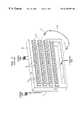
- FIG. 2is a perspective view of a tracing interface module and rack controller in accordance with the present invention, shown in conjunction with the prior art telecommunications rack assembly of FIG. 1;
- FIG. 3is an enlarged, fragmented view of a section of a graphics overlay on a tracing interface module
- FIG. 4is an enlarged, fragmented view of an alternate embodiment of a graphics overlay on a tracing interface module
- FIG. 5is an enlarged, fragmented view of a second alternate embodiment of a graphics overlay on a tracing interface module.
- a conventional telecommunications rack 10is shown, such as the one previously described in regard to FIG. 1 .
- the telecommunications rack 10contains a plurality of patch panels 12 that are mounted in parallel horizontal rows within the rack 10 .
- Each of the patch panels 12contains a plurality of patch port assemblies 14 .
- the connector ports 16 associated with each of the patch port assemblies 14are hard wired to the various lines that enter the telecommunications closet.
- a rack controller 30is mounted to each rack 10 in the overall patch system.
- the rack controller 30contains a central processing unit (CPU).
- the CPUis capable of independently running line tracing programs and also contains a remote access port 32 that enables the CPU to be accessed by a remote computer.
- Remote access of the rack controller 30is the subject of related co-pending patent application Ser. No. 09/247,614, entitled System And Method Of Operation For A Telecommunications Patch System, which has already been incorporated into this application by reference.
- the purpose of the rack controller 30is to operate and gather data from the various tracing interface modules 34 , as will be later explained.
- the tracing interface modules 34are modules that mount to the face of each patch panel 12 on the rack 10 .
- the tracing interface modules 34are positioned above the various connector ports 16 located on a patch panels 12 and provide an interface through which data about each connector port 16 can be transmitted to and from the rack controller 30 .
- the tracing interface module 34can have multiple different configurations. In the shown embodiment, the tracing interface module 34 mounts to the face surface of the patch panel 12 above the connector ports 16 . From FIG. 2, it can be seen that extending below each tracing interface module 34 are a plurality of sensors 38 . Each sensor 38 corresponds in position with one of the connector ports 16 on the patch panel 12 . As the terminated end of a patch cord 20 (FIG. 1) is connected to a connector port 16 , the presence of the patch cord is detected by a sensor 38 and read to the rack controller 30 . The rack controller 30 is therefore capable of automatically determining when a patch cord has been added or removed from any connector port 16 on the rack 10 .
- the sensors 38are mechanical elements. It should be understood that the use of such sensor is merely exemplary and passive optical-based or electrical based sensors can also be used. The use of alternate embodiments of sensors is described in co-pending patent application Ser. No. 09/247,270, entitled Method And Device For Detecting The Presence Of A Patch Cord Connector In A Telecommunications Patch System; and U.S. patent application Ser. No. 09/404,420, entitled System And Method For Identifying Specific Patch Cord Connectors In A Telecommunications Patch System. Both of these co-pending applications have been incorporated into this disclosure by reference.
- the shown tracing interface module 34also contains a graphics overlay 40 .
- the graphics overlay 40is the part of the tracing interface module 34 that is viewed by a technician. Accordingly, the ability of a tracing interface module 34 to identify a specific connector port 16 is transmitted through the structure of the graphics overlay 40 .
- the graphics overlay 40contains surface visible light emitting diodes (LEDs) 42 and tracing buttons 44 .
- LEDssurface visible light emitting diodes
- An LED 42 and tracing button 44are provided for each connector port 16 when the tracing interface module 34 is connected to the patch panel 12 (FIG. 2 ). Accordingly, once the tracing interface module 34 is in place, each connector port 16 on the patch panel has an LED 42 and tracing button 44 that corresponds in position to that connector port 16 .
- An indiciamay be printed on each of the tracing buttons 44 to help identify the different tracing buttons 44 .
- a liquid crystal display (LCD) 50is disposed below the LEDs 42 and trace buttons 44 . The LCD 50 is used to display informative messages as will later be described.
- the rack controller 30is therefore capable of monitoring any and all changes that occur to the patch cords in the patch system over time.
- the rack controller 30is therefore capable of automatically keeping an accurate log of all changes that have occurred to the patch cords since the installation of the present invention system. Accordingly, if a technician is servicing the patch system, that technician can read the accurate log straight from the rack controller 30 .
- the logcan be read out on the display 52 of the rack controller 30 or can be remotely accessed via the connector port 32 on the rack controller 30 .
- the tracing systemcan also be used to accurately trace the end points of any patch cord 20 (FIG. 1 ). For instance, suppose a technician wants to find the opposite end of a particular patch cord. That technician can press the trace button 38 that corresponds in position to the known end of the patch cord. Upon the pressing of the trace button 38 , the rack controller 30 will review its own log and will determine where the opposite end of that patch cord is located. The rack controller will then light the LED 42 that corresponds in position to the opposite end of the targeted patch cord. The technician then need only look for the lit LED 42 on one of the tracing interface modules 34 to find the opposite end of the targeted patch cord. The wasted time and inaccuracy of manually tracing patch cords are eliminated.
- At least one liquid crystal display (LCD) 50is contained within the graphics overlay 40 of the tracing interface module 34 .
- the LCD 50can extend across the entire tracing interface module 34 .
- four separate LCDs 40are provided, wherein each LCD 40 is positioned over the connector ports 16 in one patch port assemblies 14 on a patch panel 12 .
- the rack controller 30may also display instructions or useful information on the LCDs 40 in the form, for example, of alpha numeric characters. For example, the location of a patch cord by rack number and patch panel may be displayed. Similarly an icon may flash that corresponds in position to the connector port 16 identified during a tracing procedure. Alternatively, the identity of the patch cord may be displayed, thereby helping a technician verify that he/she is servicing the correct patch cord.
- the LCD 40By using the LCD 40 to automatically identify each connector port 16 , paper labels become obsolete.
- FIG. 4an alternate embodiment of a graphics overlay 60 for the tracing interface module is shown.
- a touch screen 62is provided in place of the previously described LCDs.
- the use of a touch screen 62eliminates the need for separate trace buttons. Rather, in order for a technician to initiate a trace, that technician need only touch the touch screen 62 above a particular connector port.
- the rack controller 30(FIG. 2) would treat the touching of the touch screen 62 in the same manner as the touching of a trace button.
- the need for an LED for each connector port 16can also be eliminated. Rather, the touch screen 62 can flash, thereby providing a clearly visible location indication to a technician performing a trace.
- Using an embodiment of the graphics overlay that contains an electronic displayalso enables data to displayed within the telecommunications closet that has been transmitted to the telecommunications closet from a remote location. This enables technicians to receive and execute paperless work orders. Transmitting data to and from a telecommunications closet from a remote location is described in co-pending patent application Ser. No. 09/247,614, entitled, System And Method Of Operation For A Telecommunications Patch System.
- FIG. 5a simplified version of a graphics overlay 70 is shown.
- the graphic overlay 70 for the tracing interface module 34contains light emitting diodes (LEDs) 72 and tracing buttons 74 positioned within individual graphics boxes 76 .
- a graphics box 76 with an LED 72 and tracing button 74is provided for each connector port 16 when the tracing interface module 34 is connected to the patch panel. Accordingly, once the tracing interface module 34 is in place, each connector port 16 on the patch panel has an LED 72 and tracing button 74 that corresponds in position to that connector port 16 .
- Each graphics box 76also contains an indicia that is printed on each of the tracing buttons 74 to help identify the different tracing buttons 74 . Additionally, a labeling area 78 is provided in each graphics box 76 below each tracing button 74 for further identification. Each labeling area 78 can be written upon to identify the port in a manner useful to the system's technician.
- the graphics overlaycontained a means for indicating the location of a specific connector port, a means for initiating a patch cord trace and an identifying means for identifying the patch cord terminations.
Landscapes
- Engineering & Computer Science (AREA)
- Computer Networks & Wireless Communication (AREA)
- Monitoring And Testing Of Exchanges (AREA)
- Structure Of Telephone Exchanges (AREA)
Abstract
Description
Claims (19)
Priority Applications (2)
| Application Number | Priority Date | Filing Date | Title |
|---|---|---|---|
| US09/247,385US6330307B1 (en) | 1999-02-10 | 1999-02-10 | Display panel overlay structure and method for tracing interface modules in a telecommunications patch system |
| GB0002213AGB2347751B (en) | 1999-02-10 | 2000-01-31 | Display panel overlay structure and method for tracing interface modules in a telecommunications patch system |
Applications Claiming Priority (1)
| Application Number | Priority Date | Filing Date | Title |
|---|---|---|---|
| US09/247,385US6330307B1 (en) | 1999-02-10 | 1999-02-10 | Display panel overlay structure and method for tracing interface modules in a telecommunications patch system |
Publications (1)
| Publication Number | Publication Date |
|---|---|
| US6330307B1true US6330307B1 (en) | 2001-12-11 |
Family
ID=22934730
Family Applications (1)
| Application Number | Title | Priority Date | Filing Date |
|---|---|---|---|
| US09/247,385Expired - LifetimeUS6330307B1 (en) | 1999-02-10 | 1999-02-10 | Display panel overlay structure and method for tracing interface modules in a telecommunications patch system |
Country Status (2)
| Country | Link |
|---|---|
| US (1) | US6330307B1 (en) |
| GB (1) | GB2347751B (en) |
Cited By (102)
| Publication number | Priority date | Publication date | Assignee | Title |
|---|---|---|---|---|
| US6522737B1 (en)* | 1999-02-10 | 2003-02-18 | Avaya Technology Corp. | System and method of operation for a telecommunications patch system |
| US20030204356A1 (en)* | 1999-04-06 | 2003-10-30 | David Solomon I. | System for monitoring connection pattern of data ports |
| WO2005032162A1 (en)* | 2003-09-26 | 2005-04-07 | Hellermanntyton Data Limited | Structured cabling system and patching method |
| DE102004033940A1 (en)* | 2004-07-14 | 2006-02-16 | Tkm Telekommunikation Und Elektronik Gmbh | Connector identification system for identifying multi-pole plug-in connectors for data-transmission cables in panels with manifold sockets has detectors/LEDs assigned to individual sockets |
| US20060094291A1 (en)* | 2004-11-03 | 2006-05-04 | Caveney Jack E | Method and apparatus for patch panel patch cord documentation and revision |
| US20060148279A1 (en)* | 2004-12-06 | 2006-07-06 | Commscope Solutions Properties, Llc | Telecommunications patching system that utilizes RFID tags to detect and identify patch cord interconnections |
| US20060282529A1 (en)* | 2005-06-14 | 2006-12-14 | Panduit Corp. | Method and apparatus for monitoring physical network topology information |
| US20070132503A1 (en)* | 2005-12-06 | 2007-06-14 | Panduit Corp. | Power patch panel with guided mac capability |
| US20070230452A1 (en)* | 2006-03-22 | 2007-10-04 | Steve Hough | Intelligent patching system and method |
| US20070243725A1 (en)* | 2005-08-26 | 2007-10-18 | Panduit Corp. | Patch Field Documentation and Revision Systems |
| US20070286411A1 (en)* | 2006-05-26 | 2007-12-13 | Nsgdatacom, Inc. | Patch panel apparatus and system including patch cord path tracing |
| US20080043631A1 (en)* | 2005-05-19 | 2008-02-21 | Panduit Corp. | Method and Apparatus for Documenting Network Paths |
| US20080122579A1 (en)* | 2006-11-29 | 2008-05-29 | Commscope Solutions Properties, Llc | Telecommunications patching system that facilitates detection and identification of patch cords |
| US20080214140A1 (en)* | 2005-09-28 | 2008-09-04 | Panduit Corp. | Powered patch panel |
| US7455527B2 (en) | 2004-05-03 | 2008-11-25 | Panduit Corp. | Powered patch panel |
| US7488206B2 (en) | 2006-02-14 | 2009-02-10 | Panduit Corp. | Method and apparatus for patch panel patch cord documentation and revision |
| US7519000B2 (en) | 2002-01-30 | 2009-04-14 | Panduit Corp. | Systems and methods for managing a network |
| US20090096581A1 (en)* | 2007-10-12 | 2009-04-16 | Commscope, Inc. Of North Carolina | Communications Patching Systems with Radio Frequency Identification Antenna Switching Circuits |
| US7547150B2 (en) | 2007-03-09 | 2009-06-16 | Corning Cable Systems, Llc | Optically addressed RFID elements |
| US20090168435A1 (en)* | 2007-12-27 | 2009-07-02 | Asustek Computer Inc. | Electronic Device that Facilitate Locating Connection Port Thereof |
| US20090166404A1 (en)* | 2008-01-02 | 2009-07-02 | Commscope, Inc. Of North Carolina | Intelligent MPO-to-MPO Patch Panels Having Connectivity Tracking Capabilities and Related Methods |
| US20090215310A1 (en)* | 2006-10-10 | 2009-08-27 | Adc Gmbh | Upgradeable telecommunications patch panel and method of upgrading same |
| US20090225667A1 (en)* | 1997-11-17 | 2009-09-10 | Adc Telecommunications, Inc. | System and method for electronically identifying connections of a cross-connect system |
| US7636050B2 (en) | 2005-08-08 | 2009-12-22 | Panduit Corp. | Systems and methods for detecting a patch cord end connection |
| US20100011097A1 (en)* | 2008-07-11 | 2010-01-14 | Terry Cobb | Methods of Using Control Communications to Identify Devices that are Connected Through a Communications Patching System and Related Communications Patching Systems |
| US7656903B2 (en) | 2002-01-30 | 2010-02-02 | Panduit Corp. | System and methods for documenting networks with electronic modules |
| US20100052856A1 (en)* | 2008-09-03 | 2010-03-04 | Macauley Daniel W | Radio Frequency Identification Triangulation Systems for Communications Patching Systems and Related Methods of Determining Patch Cord Connectivity Information |
| US20100105244A1 (en)* | 2008-10-29 | 2010-04-29 | Scott Martin Keith | Telecommunications Patching Systems with Obliquely-Angled Patching Modules |
| US20100157516A1 (en)* | 2008-12-22 | 2010-06-24 | Panduit Corp. | Physical infrastructure management system |
| US20100176958A1 (en)* | 2007-04-05 | 2010-07-15 | Walter Koch | Electrically Adjustable Piece of Furniture and Method of Diagnosing an Operating State for an Electrically Adjustable Piece of Furniture |
| US7760094B1 (en) | 2006-12-14 | 2010-07-20 | Corning Cable Systems Llc | RFID systems and methods for optical fiber network deployment and maintenance |
| US20100184323A1 (en)* | 2008-11-12 | 2010-07-22 | Panduit Corp. | Patch Cord with Insertion Detection and Light Illumination Capabilities |
| US7772975B2 (en) | 2006-10-31 | 2010-08-10 | Corning Cable Systems, Llc | System for mapping connections using RFID function |
| US20100210134A1 (en)* | 2009-02-19 | 2010-08-19 | Panduit Corp. | Cross connect patch guidance system |
| US20100211665A1 (en)* | 2009-02-13 | 2010-08-19 | Adc Telecommunications, Inc. | Network management systems for use with physical layer information |
| US7782202B2 (en) | 2006-10-31 | 2010-08-24 | Corning Cable Systems, Llc | Radio frequency identification of component connections |
| US20100224578A1 (en)* | 2009-03-09 | 2010-09-09 | Patrick Fariello | Methods of Converting Patching System To Intelligent Patching System and Related Shelf Units |
| US7811119B2 (en) | 2005-11-18 | 2010-10-12 | Panduit Corp. | Smart cable provisioning for a patch cord management system |
| US20100267274A1 (en)* | 2007-10-19 | 2010-10-21 | Panduit Corp | Communication port identification system |
| US20110008996A1 (en)* | 2009-06-29 | 2011-01-13 | Gregory Pinn | Dynamic Labeling of Patch Panel Ports |
| US20110043371A1 (en)* | 2009-08-21 | 2011-02-24 | Michael German | Systems, Equipment and Methods for Automatically Tracking Cable Connections and for Identifying Work Area Devices and Related Methods of Operating Communications Networks |
| US20110043333A1 (en)* | 2009-08-21 | 2011-02-24 | Michael German | Systems for Automatically Tracking Patching Connections to Network Devices Using a Separate Control Channel and Related Patching Equipment and Methods |
| US7938700B2 (en) | 2008-02-21 | 2011-05-10 | Panduit Corp. | Intelligent inter-connect and cross-connect patching system |
| US20110185012A1 (en)* | 2010-01-27 | 2011-07-28 | Colley Matthew D | System and method for generating a notification mailing list |
| US20110211456A1 (en)* | 2006-12-13 | 2011-09-01 | Panduit Corp. | High Performance Three-Port Switch For Managed Ethernet Systems |
| US20110235979A1 (en)* | 2010-02-12 | 2011-09-29 | John Anderson | Managed fiber connectivity systems |
| US20120040609A1 (en)* | 2010-08-13 | 2012-02-16 | Research In Motion Limited | Near-field communication (nfc) system providing plug-in device connection assistance features and related methods |
| US8142221B2 (en) | 2010-04-19 | 2012-03-27 | Tyco Electronics Corporation | Plug assembly for a connectivity management system |
| US8152560B2 (en) | 2010-04-19 | 2012-04-10 | Tyco Electronics Corporation | Connectivity sensing assembly |
| US8248208B2 (en) | 2008-07-15 | 2012-08-21 | Corning Cable Systems, Llc. | RFID-based active labeling system for telecommunication systems |
| US8264355B2 (en) | 2006-12-14 | 2012-09-11 | Corning Cable Systems Llc | RFID systems and methods for optical fiber network deployment and maintenance |
| USRE43774E1 (en) | 2007-04-12 | 2012-10-30 | Commscope, Inc. Of North Carolina | Systems and methods of identifying patch cord connections in a communications patching system using common mode transmission |
| US8325770B2 (en) | 2003-08-06 | 2012-12-04 | Panduit Corp. | Network managed device installation and provisioning technique |
| US8565572B2 (en) | 2010-06-23 | 2013-10-22 | Adc Telecommunications, Inc. | Telecommunications assembly |
| US8596882B2 (en) | 2009-10-16 | 2013-12-03 | Adc Telecommunications, Inc. | Managed connectivity in fiber optic systems and methods thereof |
| US20130329344A1 (en)* | 2012-06-11 | 2013-12-12 | Commscope, Inc. Of North Carolina | Intelligent telecommunications patching system |
| WO2014008132A1 (en)* | 2012-07-06 | 2014-01-09 | Adc Telecommunications, Inc. | Managed electrical connectivity systems |
| US8638651B2 (en) | 2011-01-21 | 2014-01-28 | Commscope, Inc. Of North Carolina | Intelligent patching systems and methods using phantom mode control signals and related communications connectors |
| US8696369B2 (en) | 2010-09-09 | 2014-04-15 | Adc Telecommunications, Inc. | Electrical plug with main contacts and retractable secondary contacts |
| US20140111346A1 (en)* | 2009-06-29 | 2014-04-24 | Commscope, Inc. Of North Carolina | Methods of Automatically Recording Patching Changes at Passive Patch Panels and Network Equipment |
| US8715012B2 (en) | 2011-04-15 | 2014-05-06 | Adc Telecommunications, Inc. | Managed electrical connectivity systems |
| US8731405B2 (en) | 2008-08-28 | 2014-05-20 | Corning Cable Systems Llc | RFID-based systems and methods for collecting telecommunications network information |
| US8757895B2 (en) | 2011-04-15 | 2014-06-24 | Adc Telecommunications, Inc. | Managed fiber connectivity systems |
| US8832503B2 (en) | 2011-03-25 | 2014-09-09 | Adc Telecommunications, Inc. | Dynamically detecting a defective connector at a port |
| US8874814B2 (en) | 2010-06-11 | 2014-10-28 | Adc Telecommunications, Inc. | Switch-state information aggregation |
| US8897637B2 (en) | 2009-04-22 | 2014-11-25 | Adc Gmbh | Method and arrangement for identifying at least one object |
| US8923013B2 (en) | 2010-02-12 | 2014-12-30 | Adc Telecommunications, Inc. | Communications bladed panel systems |
| US8992261B2 (en) | 2010-10-22 | 2015-03-31 | Adc Telecommunications, Inc. | Single-piece plug nose with multiple contact sets |
| US8992260B2 (en) | 2009-10-16 | 2015-03-31 | Adc Telecommunications, Inc. | Managed connectivity in electrical systems and methods thereof |
| US9038141B2 (en) | 2011-12-07 | 2015-05-19 | Adc Telecommunications, Inc. | Systems and methods for using active optical cable segments |
| US9054440B2 (en) | 2009-10-19 | 2015-06-09 | Adc Telecommunications, Inc. | Managed electrical connectivity systems |
| US9064022B2 (en) | 2011-05-17 | 2015-06-23 | Adc Telecommunications, Inc. | Component identification and tracking system for telecommunication networks |
| US9081537B2 (en) | 2011-03-25 | 2015-07-14 | Adc Telecommunications, Inc. | Identifier encoding scheme for use with multi-path connectors |
| US9203198B2 (en) | 2012-09-28 | 2015-12-01 | Commscope Technologies Llc | Low profile faceplate having managed connectivity |
| US9207417B2 (en) | 2012-06-25 | 2015-12-08 | Adc Telecommunications, Inc. | Physical layer management for an active optical module |
| US9219543B2 (en) | 2012-07-11 | 2015-12-22 | Commscope Technologies Llc | Monitoring optical decay in fiber connectivity systems |
| US9285552B2 (en) | 2013-02-05 | 2016-03-15 | Commscope Technologies Llc | Optical assemblies with managed connectivity |
| US9379501B2 (en) | 2013-02-05 | 2016-06-28 | Commscope Technologies Llc | Optical assemblies with managed connectivity |
| US9380874B2 (en) | 2012-07-11 | 2016-07-05 | Commscope Technologies Llc | Cable including a secure physical layer management (PLM) whereby an aggregation point can be associated with a plurality of inputs |
| US9407510B2 (en) | 2013-09-04 | 2016-08-02 | Commscope Technologies Llc | Physical layer system with support for multiple active work orders and/or multiple active technicians |
| US9423570B2 (en) | 2013-02-05 | 2016-08-23 | Commscope Technologies Llc | Optical assemblies with managed connectivity |
| US9453971B2 (en) | 2012-07-11 | 2016-09-27 | Commscope Technologies Llc | Managed fiber connectivity systems |
| US9470742B2 (en) | 2012-08-03 | 2016-10-18 | Commscope Technologies Llc | Managed fiber connectivity systems |
| US9473361B2 (en) | 2012-07-11 | 2016-10-18 | Commscope Technologies Llc | Physical layer management at a wall plate device |
| US9497098B2 (en) | 2011-03-25 | 2016-11-15 | Commscope Technologies Llc | Event-monitoring in a system for automatically obtaining and managing physical layer information using a reliable packet-based communication protocol |
| US9500814B2 (en) | 2014-03-26 | 2016-11-22 | Commscope Technologies Llc | Optical adapter module with managed connectivity |
| WO2016193445A1 (en)* | 2015-06-03 | 2016-12-08 | Hirschmann Automation And Control Gmbh | Vlan-port-signaling |
| US9544058B2 (en) | 2013-09-24 | 2017-01-10 | Commscope Technologies Llc | Pluggable active optical module with managed connectivity support and simulated memory table |
| US9563832B2 (en) | 2012-10-08 | 2017-02-07 | Corning Incorporated | Excess radio-frequency (RF) power storage and power sharing RF identification (RFID) tags, and related connection systems and methods |
| US9590761B2 (en) | 2011-09-23 | 2017-03-07 | Commscope Technologies Llc | Detective passive RF components using radio frequency identification tags |
| US9678133B2 (en) | 2012-03-12 | 2017-06-13 | Commscope, Inc. Of North Carolina | Intelligent patching systems and methods using electrical cable diagnostic tests and inference-based mapping techniques |
| US9798096B2 (en) | 2014-02-07 | 2017-10-24 | Commscope Technologies Llc | Managed fiber connectivity systems |
| US10153954B2 (en) | 2013-08-14 | 2018-12-11 | Commscope Technologies Llc | Inferring physical layer connection status of generic cables from planned single-end connection events |
| US10234648B2 (en) | 2007-08-06 | 2019-03-19 | Commscope Technologies Llc | Fiber optic enclosure with internal cable spool |
| US10366034B2 (en) | 2016-05-18 | 2019-07-30 | Commscope, Inc. Of North Carolina | Infrastructure management system with support for breakout cables |
| US10371914B2 (en) | 2011-06-24 | 2019-08-06 | Commscope Technologies Llc | Fiber termination enclosure with modular plate assemblies |
| US10545305B2 (en) | 2012-12-19 | 2020-01-28 | CommScope Connectivity Belgium BVBA | Distribution device with incrementally added splitters |
| US10627592B2 (en) | 2007-05-07 | 2020-04-21 | Commscope Technologies Llc | Fiber optic assembly with cable spool |
| US10938167B2 (en) | 2018-03-06 | 2021-03-02 | Commscope Technologies Llc | Automated capture of information about fixed cabling |
| US11113642B2 (en) | 2012-09-27 | 2021-09-07 | Commscope Connectivity Uk Limited | Mobile application for assisting a technician in carrying out an electronic work order |
| US11558680B2 (en) | 2019-09-12 | 2023-01-17 | Commscope Technologies Llc | Internet of things (IOT) system for cabling infrastructure |
| CN116744148A (en)* | 2023-07-28 | 2023-09-12 | 引澜科技(上海)有限公司 | An electronic distribution frame with independent display port digital ID and color LED labels |
Families Citing this family (3)
| Publication number | Priority date | Publication date | Assignee | Title |
|---|---|---|---|---|
| US6470582B1 (en) | 2000-07-31 | 2002-10-29 | Rencon | Apparatus and method of drawing a line perpendicular to a reference line |
| US7686643B2 (en) | 2007-09-18 | 2010-03-30 | Tyco Electronics Corporation | Method and apparatus for visual indication in cable network systems |
| EP2528012A1 (en)* | 2011-05-27 | 2012-11-28 | Data-Complex GmbH | Device, system and method for monitoring a number of holder devices |
Citations (11)
| Publication number | Priority date | Publication date | Assignee | Title |
|---|---|---|---|---|
| US3573792A (en)* | 1968-11-12 | 1971-04-06 | Us Navy | Universal display panel |
| US4018997A (en)* | 1974-05-10 | 1977-04-19 | Amp Incorporated | Pluggable key set telephone cross connect device |
| US4096359A (en)* | 1976-10-12 | 1978-06-20 | International Standard Electric Corporation | Key telephone system interconnection apparatus |
| US4140885A (en)* | 1974-06-19 | 1979-02-20 | Bunker Ramo Corporation | Modular interchange termination system |
| US4196316A (en)* | 1977-09-13 | 1980-04-01 | Bell Telephone Laboratories, Incorporated | Program controlled communication system having individually rearrangeable line selection |
| US4796294A (en)* | 1986-12-02 | 1989-01-03 | Kabushiki Kaisha Toshiba | Electronic telephone exchange and method of connecting ports of the exchange |
| US5550755A (en)* | 1994-07-14 | 1996-08-27 | Martin; B. Morgan | Apparatus and method for patch recording and recall |
| US5727055A (en)* | 1995-05-17 | 1998-03-10 | Ies Technologies, Inc. | Information communication systems |
| US5832071A (en)* | 1995-11-24 | 1998-11-03 | Voelker Technologies, Inc. | Electronic patching system for telecommunications devices |
| US5854824A (en)* | 1994-09-04 | 1998-12-29 | Rit Technologies Ltd. | Connectivity scanner |
| US6222908B1 (en)* | 1999-09-23 | 2001-04-24 | Avaya Technology Corp. | Method and device for identifying a specific patch cord connector as it is introduced into, or removed from, a telecommunications patch system |
Family Cites Families (6)
| Publication number | Priority date | Publication date | Assignee | Title |
|---|---|---|---|---|
| DE3308682C2 (en)* | 1983-03-11 | 1985-12-05 | Krone Gmbh, 1000 Berlin | Matrix main distributor |
| JP3054899B2 (en)* | 1993-03-02 | 2000-06-19 | 富士通電装株式会社 | Wiring management method |
| US5448675A (en)* | 1994-06-09 | 1995-09-05 | At&T Ipm Corp. | Telecommunications distribution frame with tracing |
| US5461693A (en)* | 1994-07-14 | 1995-10-24 | At&T Ipm Corp. | Optical fiber distribution frame with fiber testing |
| DE19509619A1 (en)* | 1995-03-21 | 1996-09-26 | Edmond Graesser | Management of several network distribution cabinets |
| US6421322B1 (en)* | 1997-11-17 | 2002-07-16 | Adc Telecommunications, Inc. | System and method for electronically identifying connections of a cross-connect system |
- 1999
- 1999-02-10USUS09/247,385patent/US6330307B1/ennot_activeExpired - Lifetime
- 2000
- 2000-01-31GBGB0002213Apatent/GB2347751B/ennot_activeExpired - Fee Related
Patent Citations (11)
| Publication number | Priority date | Publication date | Assignee | Title |
|---|---|---|---|---|
| US3573792A (en)* | 1968-11-12 | 1971-04-06 | Us Navy | Universal display panel |
| US4018997A (en)* | 1974-05-10 | 1977-04-19 | Amp Incorporated | Pluggable key set telephone cross connect device |
| US4140885A (en)* | 1974-06-19 | 1979-02-20 | Bunker Ramo Corporation | Modular interchange termination system |
| US4096359A (en)* | 1976-10-12 | 1978-06-20 | International Standard Electric Corporation | Key telephone system interconnection apparatus |
| US4196316A (en)* | 1977-09-13 | 1980-04-01 | Bell Telephone Laboratories, Incorporated | Program controlled communication system having individually rearrangeable line selection |
| US4796294A (en)* | 1986-12-02 | 1989-01-03 | Kabushiki Kaisha Toshiba | Electronic telephone exchange and method of connecting ports of the exchange |
| US5550755A (en)* | 1994-07-14 | 1996-08-27 | Martin; B. Morgan | Apparatus and method for patch recording and recall |
| US5854824A (en)* | 1994-09-04 | 1998-12-29 | Rit Technologies Ltd. | Connectivity scanner |
| US5727055A (en)* | 1995-05-17 | 1998-03-10 | Ies Technologies, Inc. | Information communication systems |
| US5832071A (en)* | 1995-11-24 | 1998-11-03 | Voelker Technologies, Inc. | Electronic patching system for telecommunications devices |
| US6222908B1 (en)* | 1999-09-23 | 2001-04-24 | Avaya Technology Corp. | Method and device for identifying a specific patch cord connector as it is introduced into, or removed from, a telecommunications patch system |
Cited By (285)
| Publication number | Priority date | Publication date | Assignee | Title |
|---|---|---|---|---|
| US20090225667A1 (en)* | 1997-11-17 | 2009-09-10 | Adc Telecommunications, Inc. | System and method for electronically identifying connections of a cross-connect system |
| US9742633B2 (en) | 1997-11-17 | 2017-08-22 | Commscope Technologies Llc | System and method for electronically identifying connections of a system used to make connections |
| US7907537B2 (en) | 1997-11-17 | 2011-03-15 | Adc Telecommunications, Inc. | System and method for electronically identifying connections of a cross-connect system |
| US8804540B2 (en) | 1997-11-17 | 2014-08-12 | Adc Telecommunications, Inc. | System and method for electronically identifying connections of a cross-connect system |
| US20110188383A1 (en)* | 1997-11-17 | 2011-08-04 | Adc Telecommunications, Inc. | System and method for electronically identifying connections of a cross-connect system |
| US6522737B1 (en)* | 1999-02-10 | 2003-02-18 | Avaya Technology Corp. | System and method of operation for a telecommunications patch system |
| US20030204356A1 (en)* | 1999-04-06 | 2003-10-30 | David Solomon I. | System for monitoring connection pattern of data ports |
| US6725177B2 (en)* | 1999-04-06 | 2004-04-20 | Itracs Corporation | System for monitoring connection pattern of data ports |
| US7519000B2 (en) | 2002-01-30 | 2009-04-14 | Panduit Corp. | Systems and methods for managing a network |
| US7656903B2 (en) | 2002-01-30 | 2010-02-02 | Panduit Corp. | System and methods for documenting networks with electronic modules |
| US8325770B2 (en) | 2003-08-06 | 2012-12-04 | Panduit Corp. | Network managed device installation and provisioning technique |
| GB2406447B (en)* | 2003-09-26 | 2006-06-21 | Hellermanntyton Data Ltd | Structured cabling system and patching method |
| US20070054527A1 (en)* | 2003-09-26 | 2007-03-08 | James Jason L | Structured cabling system and patching method |
| US7354298B2 (en)* | 2003-09-26 | 2008-04-08 | Hellermanntyton Data Limited | Structured cabling system and patching method |
| WO2005032162A1 (en)* | 2003-09-26 | 2005-04-07 | Hellermanntyton Data Limited | Structured cabling system and patching method |
| US7455527B2 (en) | 2004-05-03 | 2008-11-25 | Panduit Corp. | Powered patch panel |
| DE102004033940A1 (en)* | 2004-07-14 | 2006-02-16 | Tkm Telekommunikation Und Elektronik Gmbh | Connector identification system for identifying multi-pole plug-in connectors for data-transmission cables in panels with manifold sockets has detectors/LEDs assigned to individual sockets |
| US20060094291A1 (en)* | 2004-11-03 | 2006-05-04 | Caveney Jack E | Method and apparatus for patch panel patch cord documentation and revision |
| US20080045075A1 (en)* | 2004-11-03 | 2008-02-21 | Panduit Corp. | Method and Apparatus for Patch Panel Patch Cord Documentation and Revision |
| US7297018B2 (en) | 2004-11-03 | 2007-11-20 | Panduit Corp. | Method and apparatus for patch panel patch cord documentation and revision |
| US7517243B2 (en) | 2004-11-03 | 2009-04-14 | Panduit Corp. | Method and apparatus for patch panel patch cord documentation and revision |
| US7605707B2 (en) | 2004-12-06 | 2009-10-20 | Commscope, Inc. Of North Carolina | Telecommunications patching system that utilizes RFID tags to detect and identify patch cord interconnections |
| US20060148279A1 (en)* | 2004-12-06 | 2006-07-06 | Commscope Solutions Properties, Llc | Telecommunications patching system that utilizes RFID tags to detect and identify patch cord interconnections |
| US20080043631A1 (en)* | 2005-05-19 | 2008-02-21 | Panduit Corp. | Method and Apparatus for Documenting Network Paths |
| US7613124B2 (en) | 2005-05-19 | 2009-11-03 | Panduit Corp. | Method and apparatus for documenting network paths |
| US7756047B2 (en) | 2005-05-19 | 2010-07-13 | Panduit Corp. | Method and apparatus for documenting network paths |
| US20060282529A1 (en)* | 2005-06-14 | 2006-12-14 | Panduit Corp. | Method and apparatus for monitoring physical network topology information |
| US8482421B2 (en) | 2005-08-08 | 2013-07-09 | Panduit Corp. | Systems and methods for detecting a patch cord end connection |
| US7969320B2 (en) | 2005-08-08 | 2011-06-28 | Panduit Corp. | Systems and methods for detecting a patch cord end connection |
| US7636050B2 (en) | 2005-08-08 | 2009-12-22 | Panduit Corp. | Systems and methods for detecting a patch cord end connection |
| US20070243725A1 (en)* | 2005-08-26 | 2007-10-18 | Panduit Corp. | Patch Field Documentation and Revision Systems |
| US7563102B2 (en) | 2005-08-26 | 2009-07-21 | Panduit Corp. | Patch field documentation and revision systems |
| US9049499B2 (en) | 2005-08-26 | 2015-06-02 | Panduit Corp. | Patch field documentation and revision systems |
| US7978845B2 (en) | 2005-09-28 | 2011-07-12 | Panduit Corp. | Powered patch panel |
| US20080214140A1 (en)* | 2005-09-28 | 2008-09-04 | Panduit Corp. | Powered patch panel |
| US7811119B2 (en) | 2005-11-18 | 2010-10-12 | Panduit Corp. | Smart cable provisioning for a patch cord management system |
| US20070132503A1 (en)* | 2005-12-06 | 2007-06-14 | Panduit Corp. | Power patch panel with guided mac capability |
| US7768418B2 (en) | 2005-12-06 | 2010-08-03 | Panduit Corp. | Power patch panel with guided MAC capability |
| US7534137B2 (en) | 2006-02-14 | 2009-05-19 | Panduit Corp. | Method and apparatus for patch panel patch cord documentation and revision |
| US7488206B2 (en) | 2006-02-14 | 2009-02-10 | Panduit Corp. | Method and apparatus for patch panel patch cord documentation and revision |
| US7869426B2 (en) | 2006-03-22 | 2011-01-11 | Adc Gmbh | Intelligent patching system and method |
| US20070230452A1 (en)* | 2006-03-22 | 2007-10-04 | Steve Hough | Intelligent patching system and method |
| US20070286411A1 (en)* | 2006-05-26 | 2007-12-13 | Nsgdatacom, Inc. | Patch panel apparatus and system including patch cord path tracing |
| US8014518B2 (en)* | 2006-05-26 | 2011-09-06 | Nsgdatacom, Inc. | Patch panel apparatus and system including patch cord path tracing |
| US20090215310A1 (en)* | 2006-10-10 | 2009-08-27 | Adc Gmbh | Upgradeable telecommunications patch panel and method of upgrading same |
| US20100184324A1 (en)* | 2006-10-10 | 2010-07-22 | Adc Gmbh | Upgradeable telecommunications patch panel and method of upgrading same |
| US7811123B2 (en) | 2006-10-10 | 2010-10-12 | Adc Gmbh | Upgradeable telecommunications patch panel and method of upgrading same |
| US7641513B2 (en) | 2006-10-10 | 2010-01-05 | Adc Gmbh | Upgradeable telecommunications patch panel and method of upgrading same |
| US7782202B2 (en) | 2006-10-31 | 2010-08-24 | Corning Cable Systems, Llc | Radio frequency identification of component connections |
| US7772975B2 (en) | 2006-10-31 | 2010-08-10 | Corning Cable Systems, Llc | System for mapping connections using RFID function |
| US20080122579A1 (en)* | 2006-11-29 | 2008-05-29 | Commscope Solutions Properties, Llc | Telecommunications patching system that facilitates detection and identification of patch cords |
| US8116434B2 (en) | 2006-11-29 | 2012-02-14 | Commscope, Inc. Of North Carolina | Telecommunications patching system that facilitates detection and identification of patch cords |
| US9160117B2 (en) | 2006-11-29 | 2015-10-13 | Commscope, Inc. Of North Carolina | Telecommunications patching system that facilitates detection and identification of patch cords |
| US20110211456A1 (en)* | 2006-12-13 | 2011-09-01 | Panduit Corp. | High Performance Three-Port Switch For Managed Ethernet Systems |
| US7760094B1 (en) | 2006-12-14 | 2010-07-20 | Corning Cable Systems Llc | RFID systems and methods for optical fiber network deployment and maintenance |
| US8264355B2 (en) | 2006-12-14 | 2012-09-11 | Corning Cable Systems Llc | RFID systems and methods for optical fiber network deployment and maintenance |
| US7547150B2 (en) | 2007-03-09 | 2009-06-16 | Corning Cable Systems, Llc | Optically addressed RFID elements |
| US20100176958A1 (en)* | 2007-04-05 | 2010-07-15 | Walter Koch | Electrically Adjustable Piece of Furniture and Method of Diagnosing an Operating State for an Electrically Adjustable Piece of Furniture |
| USRE43774E1 (en) | 2007-04-12 | 2012-10-30 | Commscope, Inc. Of North Carolina | Systems and methods of identifying patch cord connections in a communications patching system using common mode transmission |
| US11009671B2 (en) | 2007-05-07 | 2021-05-18 | Commscope Technologies Llc | Fiber optic assembly with cable storage arrangement |
| US10627592B2 (en) | 2007-05-07 | 2020-04-21 | Commscope Technologies Llc | Fiber optic assembly with cable spool |
| US10788642B2 (en) | 2007-05-07 | 2020-09-29 | Commscope Technologies Llc | Fiber optic assembly with cable storage arrangement |
| US12235506B2 (en) | 2007-05-07 | 2025-02-25 | Commscope Technologies Llc | Fiber optic enclosure with external cable spool |
| US12019301B2 (en) | 2007-08-06 | 2024-06-25 | Commscope Technologies Llc | Fiber optic enclosure with internal cable spool |
| US11573390B2 (en) | 2007-08-06 | 2023-02-07 | Commscope Technologies Llc | Fiber optic enclosure with internal cable spool |
| US10996417B2 (en) | 2007-08-06 | 2021-05-04 | Commscope Technologies Llc | Fiber optic enclosure with internal cable spool and movable cover |
| US10495836B2 (en) | 2007-08-06 | 2019-12-03 | Commscope Technologies Llc | Fiber optic payout assembly including cable spool |
| US10712518B2 (en) | 2007-08-06 | 2020-07-14 | Commscope Technologies Llc | Fiber optic enclosure with lockable internal cable spool |
| US12253734B2 (en) | 2007-08-06 | 2025-03-18 | Commscope Technologies Llc | Fiber optic enclosure with internal cable spool |
| US10996418B2 (en) | 2007-08-06 | 2021-05-04 | Commscope Technologies Llc | Connecting subscribers to a fiber optic network using a cable spool |
| US10247897B2 (en) | 2007-08-06 | 2019-04-02 | Commscope Technologies Llc | Fiber optic enclosure with internal cable spool |
| US10234648B2 (en) | 2007-08-06 | 2019-03-19 | Commscope Technologies Llc | Fiber optic enclosure with internal cable spool |
| US10606015B2 (en) | 2007-08-06 | 2020-03-31 | Commscope Technologies Llc | Fiber optic payout assembly including cable spool |
| US10895705B2 (en) | 2007-08-06 | 2021-01-19 | Commscope Technologies Llc | Fiber optic enclosure with internal cable spool |
| US10606017B2 (en) | 2007-08-06 | 2020-03-31 | Commscope Technologies Llc | Fiber optic payout assembly including cable spool |
| US8461964B2 (en) | 2007-10-12 | 2013-06-11 | Commscope, Inc. Of North Carolina | Communications patching systems with radio frequency identification antenna switching circuits |
| US20090096581A1 (en)* | 2007-10-12 | 2009-04-16 | Commscope, Inc. Of North Carolina | Communications Patching Systems with Radio Frequency Identification Antenna Switching Circuits |
| US20100267274A1 (en)* | 2007-10-19 | 2010-10-21 | Panduit Corp | Communication port identification system |
| US8477031B2 (en) | 2007-10-19 | 2013-07-02 | Panduit Corp. | Communication port identification system |
| US20090168435A1 (en)* | 2007-12-27 | 2009-07-02 | Asustek Computer Inc. | Electronic Device that Facilitate Locating Connection Port Thereof |
| US7726838B2 (en)* | 2007-12-27 | 2010-06-01 | Asustek Computer Inc. | Electronic device that facilitate locating connection port thereof |
| US8203450B2 (en) | 2008-01-02 | 2012-06-19 | Commscope, Inc. | Intelligent MPO-to-MPO patch panels having connectivity tracking capabilities and related methods |
| US20090166404A1 (en)* | 2008-01-02 | 2009-07-02 | Commscope, Inc. Of North Carolina | Intelligent MPO-to-MPO Patch Panels Having Connectivity Tracking Capabilities and Related Methods |
| US8246397B2 (en) | 2008-02-21 | 2012-08-21 | Panduit Corp. | Intelligent inter-connect and cross-connect patching system |
| US9866458B2 (en) | 2008-02-21 | 2018-01-09 | Panduit Corp. | Intelligent inter-connect and cross-connect patching system |
| US7938700B2 (en) | 2008-02-21 | 2011-05-10 | Panduit Corp. | Intelligent inter-connect and cross-connect patching system |
| US8715001B2 (en) | 2008-02-21 | 2014-05-06 | Panduit Corp. | Intelligent inter-connect and cross-connect patching system |
| US8419465B2 (en) | 2008-02-21 | 2013-04-16 | Panduit Corp. | Intelligent inter-connect and cross-connect patching system |
| US20100011097A1 (en)* | 2008-07-11 | 2010-01-14 | Terry Cobb | Methods of Using Control Communications to Identify Devices that are Connected Through a Communications Patching System and Related Communications Patching Systems |
| US8248208B2 (en) | 2008-07-15 | 2012-08-21 | Corning Cable Systems, Llc. | RFID-based active labeling system for telecommunication systems |
| US8731405B2 (en) | 2008-08-28 | 2014-05-20 | Corning Cable Systems Llc | RFID-based systems and methods for collecting telecommunications network information |
| US9058529B2 (en) | 2008-08-28 | 2015-06-16 | Corning Optical Communications LLC | RFID-based systems and methods for collecting telecommunications network information |
| US8384522B2 (en) | 2008-09-03 | 2013-02-26 | Commscope, Inc. Of North Carolina | Radio frequency identification triangulation systems for communications patching systems and related methods of determining patch cord connectivity information |
| US20100052856A1 (en)* | 2008-09-03 | 2010-03-04 | Macauley Daniel W | Radio Frequency Identification Triangulation Systems for Communications Patching Systems and Related Methods of Determining Patch Cord Connectivity Information |
| US20100105244A1 (en)* | 2008-10-29 | 2010-04-29 | Scott Martin Keith | Telecommunications Patching Systems with Obliquely-Angled Patching Modules |
| US7876995B2 (en)* | 2008-10-29 | 2011-01-25 | Commscope, Inc. Of North Carolina | Telecommunications patching systems with obliquely-angled patching modules |
| US20100184323A1 (en)* | 2008-11-12 | 2010-07-22 | Panduit Corp. | Patch Cord with Insertion Detection and Light Illumination Capabilities |
| US8267706B2 (en) | 2008-11-12 | 2012-09-18 | Panduit Corp. | Patch cord with insertion detection and light illumination capabilities |
| US8708724B2 (en) | 2008-11-12 | 2014-04-29 | Panduit Corp. | Patch cord insertion detection and light illumination capabilities |
| US8414319B2 (en) | 2008-11-12 | 2013-04-09 | Panduit Corp. | Patch cord with insertion detection and light illumination capabilities |
| US20100157516A1 (en)* | 2008-12-22 | 2010-06-24 | Panduit Corp. | Physical infrastructure management system |
| US9026486B2 (en) | 2008-12-22 | 2015-05-05 | Panduit Corp. | Physical infrastructure management system |
| US8306935B2 (en) | 2008-12-22 | 2012-11-06 | Panduit Corp. | Physical infrastructure management system |
| US10516580B2 (en) | 2008-12-22 | 2019-12-24 | Panduit Corp. | Physical infrastructure management system |
| US8719205B2 (en) | 2008-12-22 | 2014-05-06 | Panduit Corp. | Physical infrastructure management system |
| US20100211664A1 (en)* | 2009-02-13 | 2010-08-19 | Adc Telecommunications, Inc. | Aggregation of physical layer information related to a network |
| US20100211665A1 (en)* | 2009-02-13 | 2010-08-19 | Adc Telecommunications, Inc. | Network management systems for use with physical layer information |
| US10554582B2 (en) | 2009-02-13 | 2020-02-04 | CommScope Technolgies LLC | System including management system to determine configuration for inter-networking device based on physical layer information of a network |
| US9491119B2 (en) | 2009-02-13 | 2016-11-08 | Commscope Technologies Llc | Network management systems for use with physical layer information |
| US9667566B2 (en) | 2009-02-13 | 2017-05-30 | Commscope Technologies Llc | Inter-networking devices for use with physical layer information |
| US9674115B2 (en) | 2009-02-13 | 2017-06-06 | Commscope Technologies Llc | Aggregation of physical layer information related to a network |
| US8982715B2 (en) | 2009-02-13 | 2015-03-17 | Adc Telecommunications, Inc. | Inter-networking devices for use with physical layer information |
| US20100215049A1 (en)* | 2009-02-13 | 2010-08-26 | Adc Telecommunications, Inc. | Inter-networking devices for use with physical layer information |
| US9742696B2 (en) | 2009-02-13 | 2017-08-22 | Commscope Technologies Llc | Network management systems for use with physical layer information |
| US10129179B2 (en) | 2009-02-13 | 2018-11-13 | Commscope Technologies Llc | Managed connectivity devices, systems, and methods |
| US20100211697A1 (en)* | 2009-02-13 | 2010-08-19 | Adc Telecommunications, Inc. | Managed connectivity devices, systems, and methods |
| US20100210134A1 (en)* | 2009-02-19 | 2010-08-19 | Panduit Corp. | Cross connect patch guidance system |
| US8382511B2 (en) | 2009-02-19 | 2013-02-26 | Panduit Corp. | Cross connect patch guidance system |
| US8128428B2 (en) | 2009-02-19 | 2012-03-06 | Panduit Corp. | Cross connect patch guidance system |
| US8721360B2 (en) | 2009-02-19 | 2014-05-13 | Panduit Corp. | Methods for patch cord guidance |
| US8753142B2 (en)* | 2009-03-09 | 2014-06-17 | Commscope, Inc. Of North Carolina | Methods of converting patching system to intelligent patching system and related shelf units |
| US20100224578A1 (en)* | 2009-03-09 | 2010-09-09 | Patrick Fariello | Methods of Converting Patching System To Intelligent Patching System and Related Shelf Units |
| US8897637B2 (en) | 2009-04-22 | 2014-11-25 | Adc Gmbh | Method and arrangement for identifying at least one object |
| US9811494B2 (en) | 2009-06-29 | 2017-11-07 | Commscope Inc. Of North Carolina | Methods of automatically recording patching changes at passive patch panels and network equipment |
| US20140111346A1 (en)* | 2009-06-29 | 2014-04-24 | Commscope, Inc. Of North Carolina | Methods of Automatically Recording Patching Changes at Passive Patch Panels and Network Equipment |
| US8643476B2 (en)* | 2009-06-29 | 2014-02-04 | Commscope, Inc. Of North Carolina | Dynamic labeling of patch panel ports |
| US10372651B2 (en) | 2009-06-29 | 2019-08-06 | Commscope, Inc. Of North Carolina | Methods of automatically recording patching changes at passive patch panels and network equipment |
| CN102598705A (en)* | 2009-06-29 | 2012-07-18 | 北卡罗来纳科姆斯科普公司 | Dynamic labeling of patch panel ports |
| CN102598705B (en)* | 2009-06-29 | 2015-06-17 | 北卡罗来纳科姆斯科普公司 | Patch panel, patch panel system and method of displaying patch cord connection information |
| US9338525B2 (en) | 2009-06-29 | 2016-05-10 | Commscope, Inc. Of North Carolina | Methods of automatically recording patching changes at passive patch panels and network equipment |
| US20110008996A1 (en)* | 2009-06-29 | 2011-01-13 | Gregory Pinn | Dynamic Labeling of Patch Panel Ports |
| US9123217B2 (en)* | 2009-06-29 | 2015-09-01 | Commscope, Inc. Of North Carolina | Methods of automatically recording patching changes at passive patch panels and network equipment |
| US20110043371A1 (en)* | 2009-08-21 | 2011-02-24 | Michael German | Systems, Equipment and Methods for Automatically Tracking Cable Connections and for Identifying Work Area Devices and Related Methods of Operating Communications Networks |
| US20110043333A1 (en)* | 2009-08-21 | 2011-02-24 | Michael German | Systems for Automatically Tracking Patching Connections to Network Devices Using a Separate Control Channel and Related Patching Equipment and Methods |
| US9538262B2 (en) | 2009-08-21 | 2017-01-03 | Commscope, Inc. Of North Carolina | Systems, equipment and methods for automatically tracking cable connections and for identifying work area devices and related methods of operating communications networks |
| US8994547B2 (en) | 2009-08-21 | 2015-03-31 | Commscope, Inc. Of North Carolina | Systems for automatically tracking patching connections to network devices using a separate control channel and related patching equipment and methods |
| US10374921B2 (en) | 2009-08-21 | 2019-08-06 | Commscope, Inc. Of North Carolina | Systems, equipment and methods for automatically tracking cable connections and for identifying work area devices and related methods of operating communications networks |
| US9176294B2 (en) | 2009-10-16 | 2015-11-03 | Tyco Electronics Services Gmbh | Managed connectivity in fiber optic systems and methods thereof |
| US10470320B2 (en) | 2009-10-16 | 2019-11-05 | Commscope Technologies Llc | Managed connectivity in electrical systems and methods thereof |
| US9401552B2 (en) | 2009-10-16 | 2016-07-26 | Commscope Technologies Llc | Managed connectivity in electrical systems and methods thereof |
| US12235494B2 (en) | 2009-10-16 | 2025-02-25 | Commscope Technologies Llc | Managed connectivity in fiber optic systems and methods thereof |
| US8992260B2 (en) | 2009-10-16 | 2015-03-31 | Adc Telecommunications, Inc. | Managed connectivity in electrical systems and methods thereof |
| US11630269B2 (en) | 2009-10-16 | 2023-04-18 | Commscope Technologies Llc | Managed connectivity in fiber optic systems and methods thereof |
| US9769939B2 (en) | 2009-10-16 | 2017-09-19 | Commscope Technologies Llc | Managed connectivity in electrical systems and methods thereof |
| US11231555B2 (en) | 2009-10-16 | 2022-01-25 | Commscope Technologies Llc | Managed connectivity in fiber optic systems and methods thereof |
| US11191173B2 (en) | 2009-10-16 | 2021-11-30 | Commscope Technologies Llc | Managed connectivity in electrical systems and methods thereof |
| US8596882B2 (en) | 2009-10-16 | 2013-12-03 | Adc Telecommunications, Inc. | Managed connectivity in fiber optic systems and methods thereof |
| US9810860B2 (en) | 2009-10-16 | 2017-11-07 | Commscope Technologies Llc | Managed connectivity in fiber optic systems and methods thereof |
| US10678001B2 (en) | 2009-10-16 | 2020-06-09 | Commscope Technologies Llc | Managed connectivity in fiber optic systems and methods thereof |
| US9967983B2 (en) | 2009-10-16 | 2018-05-08 | Commscope Technologies Llc | Managed connectivity in electrical systems and methods thereof |
| US11469560B2 (en) | 2009-10-19 | 2022-10-11 | Commscope Technologies Llc | Managed electrical connectivity systems |
| US10177514B2 (en) | 2009-10-19 | 2019-01-08 | Commscope Technologies Llc | Managed electrical connectivity systems |
| US10574008B2 (en) | 2009-10-19 | 2020-02-25 | Commscope Technologies Llc | Managed electrical connectivity systems |
| US9054440B2 (en) | 2009-10-19 | 2015-06-09 | Adc Telecommunications, Inc. | Managed electrical connectivity systems |
| US10958024B2 (en) | 2009-10-19 | 2021-03-23 | Commscope Technologies Llc | Managed electrical connectivity systems |
| US9595797B2 (en) | 2009-10-19 | 2017-03-14 | Commscope Technologies Llc | Managed electrical connectivity systems |
| US11862912B2 (en) | 2009-10-19 | 2024-01-02 | Commscope Technologies Llc | Managed electrical connectivity systems |
| US20110185012A1 (en)* | 2010-01-27 | 2011-07-28 | Colley Matthew D | System and method for generating a notification mailing list |
| US8934253B2 (en) | 2010-02-12 | 2015-01-13 | Adc Telecommunications, Inc. | Communications bladed panel systems |
| US9532481B2 (en) | 2010-02-12 | 2016-12-27 | Commscope Technologies Llc | Communications bladed panel systems |
| US12306444B2 (en) | 2010-02-12 | 2025-05-20 | Commscope Technologies Llc | Managed fiber connectivity systems |
| US9140859B2 (en) | 2010-02-12 | 2015-09-22 | Tyco Electronics Services Gmbh | Managed fiber connectivity systems |
| US9804337B2 (en) | 2010-02-12 | 2017-10-31 | Commscope Technologies Llc | Managed fiber connectivity systems |
| US20110235979A1 (en)* | 2010-02-12 | 2011-09-29 | John Anderson | Managed fiber connectivity systems |
| US10123444B2 (en) | 2010-02-12 | 2018-11-06 | Commscope Technologies Llc | Communications bladed panel systems |
| US11899246B2 (en) | 2010-02-12 | 2024-02-13 | Commscope Technologies Llc | Managed fiber connectivity systems |
| US8690593B2 (en) | 2010-02-12 | 2014-04-08 | Adc Telecommunications, Inc. | Managed fiber connectivity systems |
| US10473864B2 (en) | 2010-02-12 | 2019-11-12 | Commscope Technologies Llc | Managed fiber connectivity systems |
| US9265172B2 (en) | 2010-02-12 | 2016-02-16 | Commscope Technologies Llc | Communications bladed panel systems |
| US8934252B2 (en) | 2010-02-12 | 2015-01-13 | Adc Telecommunications, Inc. | Communications bladed panel systems |
| US11378755B2 (en) | 2010-02-12 | 2022-07-05 | Commscope Technologies Llc | Managed fiber connectivity systems |
| US9684134B2 (en) | 2010-02-12 | 2017-06-20 | Commscope Technologies Llc | Managed fiber connectivity systems |
| US9532482B2 (en) | 2010-02-12 | 2016-12-27 | Commscope Technologies Llc | Communications bladed panel systems |
| US9020319B2 (en) | 2010-02-12 | 2015-04-28 | Adc Telecommunications, Inc. | Communications bladed panel systems |
| US9198320B2 (en) | 2010-02-12 | 2015-11-24 | Tyco Electronics Services Gmbh | Communications bladed panel systems |
| US9549484B2 (en) | 2010-02-12 | 2017-01-17 | Commscope Technologies Llc | Communications bladed panel systems |
| US9417399B2 (en) | 2010-02-12 | 2016-08-16 | Commscope Technologies Llc | Managed fiber connectivity systems |
| US8923013B2 (en) | 2010-02-12 | 2014-12-30 | Adc Telecommunications, Inc. | Communications bladed panel systems |
| US10983285B2 (en) | 2010-02-12 | 2021-04-20 | Commscope Technologies Llc | Managed fiber connectivity systems |
| US9213363B2 (en) | 2010-02-12 | 2015-12-15 | Tyco Electronics Services Gmbh | Communications bladed panel systems |
| US9223105B2 (en) | 2010-02-12 | 2015-12-29 | Commscope Technologies Llc | Communications bladed panel systems |
| US10088636B2 (en) | 2010-02-12 | 2018-10-02 | Commscope Technologies Llc | Managed fiber connectivity systems |
| US9632255B2 (en) | 2010-02-12 | 2017-04-25 | Commscope Technologies Llc | Managed fiber connectivity systems |
| US8152560B2 (en) | 2010-04-19 | 2012-04-10 | Tyco Electronics Corporation | Connectivity sensing assembly |
| US8142221B2 (en) | 2010-04-19 | 2012-03-27 | Tyco Electronics Corporation | Plug assembly for a connectivity management system |
| US8874814B2 (en) | 2010-06-11 | 2014-10-28 | Adc Telecommunications, Inc. | Switch-state information aggregation |
| US8565572B2 (en) | 2010-06-23 | 2013-10-22 | Adc Telecommunications, Inc. | Telecommunications assembly |
| US10627593B2 (en) | 2010-06-23 | 2020-04-21 | Commscope Technologies Llc | Telecommunications assembly |
| US9678296B2 (en) | 2010-06-23 | 2017-06-13 | Commscope Technologies Llc | Telecommunications assembly |
| US10126516B1 (en) | 2010-06-23 | 2018-11-13 | Commscope Technologies Llc | Telecommunications assembly |
| US9995898B2 (en) | 2010-06-23 | 2018-06-12 | Commscope Technologies Llc | Telecommunications assembly |
| US10884211B2 (en) | 2010-06-23 | 2021-01-05 | Commscope Technologies Llc | Telecommunications assembly |
| US11402595B2 (en) | 2010-06-23 | 2022-08-02 | Commscope Technologies Llc | Telecommunications assembly |
| US9170392B2 (en) | 2010-06-23 | 2015-10-27 | Tyco Electronics Services Gmbh | Telecommunications assembly |
| US11789226B2 (en) | 2010-06-23 | 2023-10-17 | Commscope Technologies Llc | Telecommunications assembly |
| US10268014B2 (en) | 2010-06-23 | 2019-04-23 | Commscope Technologies Llc | Telecommunications assembly |
| US12235504B2 (en) | 2010-06-23 | 2025-02-25 | Commscope Technologies Llc | Telecommunications assembly |
| US9341802B2 (en) | 2010-06-23 | 2016-05-17 | Commscope Technologies Llc | Telecommunications assembly |
| US8626065B2 (en)* | 2010-08-13 | 2014-01-07 | Blackberry Limited | Near-field communication (NFC) system providing plug-in device connection assistance features and related methods |
| US20120040609A1 (en)* | 2010-08-13 | 2012-02-16 | Research In Motion Limited | Near-field communication (nfc) system providing plug-in device connection assistance features and related methods |
| US8696369B2 (en) | 2010-09-09 | 2014-04-15 | Adc Telecommunications, Inc. | Electrical plug with main contacts and retractable secondary contacts |
| US8992261B2 (en) | 2010-10-22 | 2015-03-31 | Adc Telecommunications, Inc. | Single-piece plug nose with multiple contact sets |
| US8947106B2 (en) | 2011-01-21 | 2015-02-03 | Commscope, Inc. Of North Carolina | Plug insertion detection circuits that sense a change in capacitance and related methods and communications connectors |
| US8952707B2 (en) | 2011-01-21 | 2015-02-10 | Commscope, Inc. Of North Carolina | Plug insertion detection circuits and related methods and communications connectors |
| US8638651B2 (en) | 2011-01-21 | 2014-01-28 | Commscope, Inc. Of North Carolina | Intelligent patching systems and methods using phantom mode control signals and related communications connectors |
| US8949496B2 (en) | 2011-03-25 | 2015-02-03 | Adc Telecommunications, Inc. | Double-buffer insertion count stored in a device attached to a physical layer medium |
| US9081537B2 (en) | 2011-03-25 | 2015-07-14 | Adc Telecommunications, Inc. | Identifier encoding scheme for use with multi-path connectors |
| US8832503B2 (en) | 2011-03-25 | 2014-09-09 | Adc Telecommunications, Inc. | Dynamically detecting a defective connector at a port |
| US9497098B2 (en) | 2011-03-25 | 2016-11-15 | Commscope Technologies Llc | Event-monitoring in a system for automatically obtaining and managing physical layer information using a reliable packet-based communication protocol |
| US8715012B2 (en) | 2011-04-15 | 2014-05-06 | Adc Telecommunications, Inc. | Managed electrical connectivity systems |
| US8944856B2 (en) | 2011-04-15 | 2015-02-03 | Adc Telecommunications, Inc. | Managed electrical connectivity systems |
| US8757895B2 (en) | 2011-04-15 | 2014-06-24 | Adc Telecommunications, Inc. | Managed fiber connectivity systems |
| US9759874B2 (en) | 2011-04-15 | 2017-09-12 | CommScope Technologies, LLC | Managed fiber connectivity systems |
| US9244229B2 (en) | 2011-04-15 | 2016-01-26 | Commscope Technologies Llc | Managed fiber connectivity systems |
| US9147983B2 (en) | 2011-04-15 | 2015-09-29 | Adc Telecommunications, Inc. | Managed electrical connectivity systems |
| US9502843B2 (en) | 2011-04-15 | 2016-11-22 | Commscope Technologies Llc | Managed electrical connectivity systems |
| US9064022B2 (en) | 2011-05-17 | 2015-06-23 | Adc Telecommunications, Inc. | Component identification and tracking system for telecommunication networks |
| US11988883B2 (en) | 2011-06-24 | 2024-05-21 | Commscope Technologies Llc | Fiber termination enclosure with modular plate assemblies |
| US10502916B2 (en) | 2011-06-24 | 2019-12-10 | Commscope Technologies Llc | Fiber termination enclosure with modular plate assemblies |
| US10935744B2 (en) | 2011-06-24 | 2021-03-02 | Commscope Technologies Llc | Fiber termination enclosure with modular plate assemblies |
| US11624884B2 (en) | 2011-06-24 | 2023-04-11 | Commscope Technologies Llc | Fiber termination enclosure with modular plate assemblies |
| US11327262B2 (en) | 2011-06-24 | 2022-05-10 | Commscope Technologies Llc | Fiber termination enclosure with modular plate assemblies |
| US10371914B2 (en) | 2011-06-24 | 2019-08-06 | Commscope Technologies Llc | Fiber termination enclosure with modular plate assemblies |
| US9590761B2 (en) | 2011-09-23 | 2017-03-07 | Commscope Technologies Llc | Detective passive RF components using radio frequency identification tags |
| US10003431B2 (en) | 2011-09-23 | 2018-06-19 | Commscope Technologies Llc | Detecting passive RF components using radio frequency identification tags |
| US10505663B2 (en)* | 2011-09-23 | 2019-12-10 | Commscope Technologies Llc | Detecting passive RF components using radio frequency identification tags |
| USRE47365E1 (en) | 2011-12-07 | 2019-04-23 | Commscope Technologies Llc | Systems and methods for using active optical cable segments |
| US9038141B2 (en) | 2011-12-07 | 2015-05-19 | Adc Telecommunications, Inc. | Systems and methods for using active optical cable segments |
| US9678133B2 (en) | 2012-03-12 | 2017-06-13 | Commscope, Inc. Of North Carolina | Intelligent patching systems and methods using electrical cable diagnostic tests and inference-based mapping techniques |
| USRE48274E1 (en)* | 2012-06-11 | 2020-10-20 | Commscope, Inc. Of North Carolina | Intelligent telecommunications patching system |
| CN103561358B (en)* | 2012-06-11 | 2018-04-03 | 北卡罗来纳科姆斯科普公司 | Smart Telecom Wiring System |
| CN103561358A (en)* | 2012-06-11 | 2014-02-05 | 北卡罗来纳科姆斯科普公司 | Smart Telecom Wiring System |
| US20130329344A1 (en)* | 2012-06-11 | 2013-12-12 | Commscope, Inc. Of North Carolina | Intelligent telecommunications patching system |
| US9620941B2 (en)* | 2012-06-11 | 2017-04-11 | Commscope, Inc. Of North Carolina | Intelligent telecommunications patching system |
| US9602897B2 (en) | 2012-06-25 | 2017-03-21 | Commscope Technologies Llc | Physical layer management for an active optical module |
| US9207417B2 (en) | 2012-06-25 | 2015-12-08 | Adc Telecommunications, Inc. | Physical layer management for an active optical module |
| WO2014008132A1 (en)* | 2012-07-06 | 2014-01-09 | Adc Telecommunications, Inc. | Managed electrical connectivity systems |
| US9093796B2 (en) | 2012-07-06 | 2015-07-28 | Adc Telecommunications, Inc. | Managed electrical connectivity systems |
| US9437990B2 (en) | 2012-07-06 | 2016-09-06 | Commscope Technologies Llc | Managed electrical connectivity systems |
| US20170108653A1 (en)* | 2012-07-11 | 2017-04-20 | Commscope Technologies Llc | Managed fiber connectivity systems |
| US9219543B2 (en) | 2012-07-11 | 2015-12-22 | Commscope Technologies Llc | Monitoring optical decay in fiber connectivity systems |
| US10050703B2 (en) | 2012-07-11 | 2018-08-14 | Commscope Technologies Llc | Monitoring optical decay in fiber connectivity systems |
| US9380874B2 (en) | 2012-07-11 | 2016-07-05 | Commscope Technologies Llc | Cable including a secure physical layer management (PLM) whereby an aggregation point can be associated with a plurality of inputs |
| US9453971B2 (en) | 2012-07-11 | 2016-09-27 | Commscope Technologies Llc | Managed fiber connectivity systems |
| US9473361B2 (en) | 2012-07-11 | 2016-10-18 | Commscope Technologies Llc | Physical layer management at a wall plate device |
| US9742704B2 (en) | 2012-07-11 | 2017-08-22 | Commscope Technologies Llc | Physical layer management at a wall plate device |
| US9470742B2 (en) | 2012-08-03 | 2016-10-18 | Commscope Technologies Llc | Managed fiber connectivity systems |
| US11113642B2 (en) | 2012-09-27 | 2021-09-07 | Commscope Connectivity Uk Limited | Mobile application for assisting a technician in carrying out an electronic work order |
| US9525255B2 (en) | 2012-09-28 | 2016-12-20 | Commscope Technologies Llc | Low profile faceplate having managed connectivity |
| US9203198B2 (en) | 2012-09-28 | 2015-12-01 | Commscope Technologies Llc | Low profile faceplate having managed connectivity |
| US9563832B2 (en) | 2012-10-08 | 2017-02-07 | Corning Incorporated | Excess radio-frequency (RF) power storage and power sharing RF identification (RFID) tags, and related connection systems and methods |
| US10545305B2 (en) | 2012-12-19 | 2020-01-28 | CommScope Connectivity Belgium BVBA | Distribution device with incrementally added splitters |
| US10268000B2 (en) | 2013-02-05 | 2019-04-23 | Commscope Technologies Llc | Optical assemblies with managed connectivity |
| US9735523B2 (en) | 2013-02-05 | 2017-08-15 | Commscope Connectivity Uk Limited | Optical assemblies with managed connectivity |
| US9379501B2 (en) | 2013-02-05 | 2016-06-28 | Commscope Technologies Llc | Optical assemblies with managed connectivity |
| US10571641B2 (en) | 2013-02-05 | 2020-02-25 | Commscope Technologies Llc | Optical assemblies with managed connectivity |
| US9423570B2 (en) | 2013-02-05 | 2016-08-23 | Commscope Technologies Llc | Optical assemblies with managed connectivity |
| US11143833B2 (en) | 2013-02-05 | 2021-10-12 | Commscope Technologies Llc | Optical assemblies with managed connectivity |
| US10746943B2 (en) | 2013-02-05 | 2020-08-18 | Commscope Technologies Llc | Optical assemblies with managed connectivity |
| US10012813B2 (en) | 2013-02-05 | 2018-07-03 | Commscope Technologies Llc | Optical assemblies with managed connectivity |
| US9778424B2 (en) | 2013-02-05 | 2017-10-03 | Commscope Technologies Llc | Optical assemblies with managed connectivity |
| US11327248B2 (en) | 2013-02-05 | 2022-05-10 | Commscope Technologies Llc | Optical assemblies with managed connectivity |
| US12235505B2 (en) | 2013-02-05 | 2025-02-25 | Commscope Technologies Llc | Fiber optic cassette arrangement |
| US11714246B2 (en) | 2013-02-05 | 2023-08-01 | Commscope Technologies Llc | Optical assemblies with contoured base |
| US9285552B2 (en) | 2013-02-05 | 2016-03-15 | Commscope Technologies Llc | Optical assemblies with managed connectivity |
| US11867952B2 (en) | 2013-02-05 | 2024-01-09 | Commscope Technologies Llc | Optical assemblies with managed connectivity |
| US10819602B2 (en) | 2013-08-14 | 2020-10-27 | Commscope Technologies Llc | Inferring physical layer connection status of generic cables from planned single-end connection events |
| US10153954B2 (en) | 2013-08-14 | 2018-12-11 | Commscope Technologies Llc | Inferring physical layer connection status of generic cables from planned single-end connection events |
| US9407510B2 (en) | 2013-09-04 | 2016-08-02 | Commscope Technologies Llc | Physical layer system with support for multiple active work orders and/or multiple active technicians |
| US9905089B2 (en) | 2013-09-04 | 2018-02-27 | Commscope Technologies Llc | Physical layer system with support for multiple active work orders and/or multiple active technicians |
| US10205519B2 (en) | 2013-09-24 | 2019-02-12 | Commscope Technologies Llc | Pluggable active optical module with managed connectivity support and simulated memory table |
| US10700778B2 (en) | 2013-09-24 | 2020-06-30 | Commscope Technologies Llc | Pluggable active optical module with managed connectivity support and simulated memory table |
| US9544058B2 (en) | 2013-09-24 | 2017-01-10 | Commscope Technologies Llc | Pluggable active optical module with managed connectivity support and simulated memory table |
| US9798096B2 (en) | 2014-02-07 | 2017-10-24 | Commscope Technologies Llc | Managed fiber connectivity systems |
| US10509177B2 (en) | 2014-03-26 | 2019-12-17 | Commscope Technologies Llc | Optical adapter module with managed connectivity |
| US9995883B2 (en) | 2014-03-26 | 2018-06-12 | Commscope Technologies Llc | Optical adapter module with managed connectivity |
| US9500814B2 (en) | 2014-03-26 | 2016-11-22 | Commscope Technologies Llc | Optical adapter module with managed connectivity |
| US10608880B2 (en) | 2015-06-03 | 2020-03-31 | Hirschmann Automation And Control Gmbh | VLAN port signaling |
| WO2016193445A1 (en)* | 2015-06-03 | 2016-12-08 | Hirschmann Automation And Control Gmbh | Vlan-port-signaling |
| US10366034B2 (en) | 2016-05-18 | 2019-07-30 | Commscope, Inc. Of North Carolina | Infrastructure management system with support for breakout cables |
| US10938167B2 (en) | 2018-03-06 | 2021-03-02 | Commscope Technologies Llc | Automated capture of information about fixed cabling |
| US11450993B2 (en) | 2018-03-06 | 2022-09-20 | Commscope Technologies Llc | Automated capture of information about fixed cabling |
| US11558680B2 (en) | 2019-09-12 | 2023-01-17 | Commscope Technologies Llc | Internet of things (IOT) system for cabling infrastructure |
| US12160693B2 (en) | 2019-09-12 | 2024-12-03 | Commscope Technologies Llc | Internet of things (IOT) system for cabling infrastructure |
| CN116744148A (en)* | 2023-07-28 | 2023-09-12 | 引澜科技(上海)有限公司 | An electronic distribution frame with independent display port digital ID and color LED labels |
Also Published As
| Publication number | Publication date |
|---|---|
| GB0002213D0 (en) | 2000-03-22 |
| GB2347751A (en) | 2000-09-13 |
| GB2347751B (en) | 2001-05-30 |
Similar Documents
| Publication | Publication Date | Title |
|---|---|---|
| US6330307B1 (en) | Display panel overlay structure and method for tracing interface modules in a telecommunications patch system | |
| US6285293B1 (en) | System and method for addressing and tracing patch cords in a dedicated telecommunications system | |
| US6234830B1 (en) | Tracing interface module for patch cords in a telecommunications system | |
| US6688910B1 (en) | System and method for automatic addressing of devices in a dedicated telecommunications system | |
| US6350148B1 (en) | Method and device for detecting the presence of a patch cord connector in a telecommunications patch system | |
| US6522737B1 (en) | System and method of operation for a telecommunications patch system | |
| US6424710B1 (en) | Method and device for detecting the presence of a patch cord connector in a telecommunications patch system using passive detection sensors | |
| US6499861B1 (en) | Illuminated patch cord connector ports for use in a telecommunications patch closet having patch cord tracing capabilities | |
| US6222908B1 (en) | Method and device for identifying a specific patch cord connector as it is introduced into, or removed from, a telecommunications patch system | |
| US8643476B2 (en) | Dynamic labeling of patch panel ports | |
| US9811494B2 (en) | Methods of automatically recording patching changes at passive patch panels and network equipment | |
| US6784802B1 (en) | Real time monitoring of cable patch panel | |
| JP2957109B2 (en) | Communication cable distribution frame | |
| US10262656B2 (en) | Multi-tier intelligent infrastructure management systems for communications systems and related equipment and methods | |
| US7605707B2 (en) | Telecommunications patching system that utilizes RFID tags to detect and identify patch cord interconnections | |
| US9924241B2 (en) | Intelligent patching systems and methods using color identification tags and related equipment | |
| US20120128136A1 (en) | Telecommunications Patching System That Facilitates Detection and Identification of Patch Cords | |
| AU2007229834A1 (en) | Intelligent patching identification system and method | |
| US7652589B2 (en) | Selecting a function of components based on orientation | |
| GB2374941A (en) | Detecting the presence of a patch cord connector in a telecommunications patch system using mechanical switches | |
| US6955477B1 (en) | Circuit assembly for monitoring port activity and integrity of a multiport media converter | |
| KR20060023549A (en) | Network connection detection assembly | |
| CN219394979U (en) | Electronic distribution frame | |
| KR102098725B1 (en) | Patch panel for connecting communication equipments | |
| US8811605B1 (en) | Intelligent patching systems and components thereof |
Legal Events
| Date | Code | Title | Description |
|---|---|---|---|
| AS | Assignment | Owner name:LUCENT TECHNOLOGIES, INC., NEW JERSEY Free format text:ASSIGNMENT OF ASSIGNORS INTEREST;ASSIGNORS:BLOCH, BRIAN MATTHEW;CHOUDHURY, GOLAM MABUD;ENSZ, LYNDON D.;AND OTHERS;REEL/FRAME:010115/0954;SIGNING DATES FROM 19990408 TO 19990618 | |
| AS | Assignment | Owner name:AVAYA TECHNOLOGY CORP, NEW JERSEY Free format text:ASSIGNMENT OF ASSIGNORS INTEREST;ASSIGNOR:LUCENT TECHNOLOGIES INC.;REEL/FRAME:012063/0272 Effective date:20000929 | |
| STCF | Information on status: patent grant | Free format text:PATENTED CASE | |
| AS | Assignment | Owner name:BANK OF NEW YORK, THE, NEW YORK Free format text:SECURITY AGREEMENT;ASSIGNOR:AVAYA TECHNOLOGY CORP.;REEL/FRAME:012775/0144 Effective date:20020405 | |
| FPAY | Fee payment | Year of fee payment:4 | |
| SULP | Surcharge for late payment | ||
| REMI | Maintenance fee reminder mailed | ||
| AS | Assignment | Owner name:AVAYA TECHNOLOGY CORPORATION, NEW JERSEY Free format text:RELEASE BY SECURED PARTY;ASSIGNOR:THE BANK OF NEW YORK;REEL/FRAME:019881/0532 Effective date:20040101 | |
| AS | Assignment | Owner name:COMMSCOPE SOLUTIONS PROPERTIES, LLC, NEVADA Free format text:ASSIGNMENT OF ASSIGNORS INTEREST;ASSIGNOR:AVAYA TECHNOLOGY CORPORATION;REEL/FRAME:019984/0028 Effective date:20040129 | |
| AS | Assignment | Owner name:COMMSCOPE, INC. OF NORTH CAROLINA, NORTH CAROLINA Free format text:MERGER;ASSIGNOR:COMMSCOPE SOLUTIONS PROPERTIES, LLC;REEL/FRAME:019991/0643 Effective date:20061220 Owner name:COMMSCOPE, INC. OF NORTH CAROLINA,NORTH CAROLINA Free format text:MERGER;ASSIGNOR:COMMSCOPE SOLUTIONS PROPERTIES, LLC;REEL/FRAME:019991/0643 Effective date:20061220 | |
| AS | Assignment | Owner name:BANK OF AMERICA, N.A., AS ADMINISTRATIVE AGENT, CA Free format text:SECURITY AGREEMENT;ASSIGNORS:COMMSCOPE, INC. OF NORTH CAROLINA;ALLEN TELECOM, LLC;ANDREW CORPORATION;REEL/FRAME:020362/0241 Effective date:20071227 Owner name:BANK OF AMERICA, N.A., AS ADMINISTRATIVE AGENT,CAL Free format text:SECURITY AGREEMENT;ASSIGNORS:COMMSCOPE, INC. OF NORTH CAROLINA;ALLEN TELECOM, LLC;ANDREW CORPORATION;REEL/FRAME:020362/0241 Effective date:20071227 | |
| FPAY | Fee payment | Year of fee payment:8 | |
| AS | Assignment | Owner name:ALLEN TELECOM LLC, NORTH CAROLINA Free format text:PATENT RELEASE;ASSIGNOR:BANK OF AMERICA, N.A., AS ADMINISTRATIVE AGENT;REEL/FRAME:026039/0005 Effective date:20110114 Owner name:ANDREW LLC (F/K/A ANDREW CORPORATION), NORTH CAROL Free format text:PATENT RELEASE;ASSIGNOR:BANK OF AMERICA, N.A., AS ADMINISTRATIVE AGENT;REEL/FRAME:026039/0005 Effective date:20110114 Owner name:COMMSCOPE, INC. OF NORTH CAROLINA, NORTH CAROLINA Free format text:PATENT RELEASE;ASSIGNOR:BANK OF AMERICA, N.A., AS ADMINISTRATIVE AGENT;REEL/FRAME:026039/0005 Effective date:20110114 | |
| AS | Assignment | Owner name:JPMORGAN CHASE BANK, N.A., AS COLLATERAL AGENT, NE Free format text:SECURITY AGREEMENT;ASSIGNORS:ALLEN TELECOM LLC, A DELAWARE LLC;ANDREW LLC, A DELAWARE LLC;COMMSCOPE, INC. OF NORTH CAROLINA, A NORTH CAROLINA CORPORATION;REEL/FRAME:026276/0363 Effective date:20110114 | |
| AS | Assignment | Owner name:JPMORGAN CHASE BANK, N.A., AS COLLATERAL AGENT, NE Free format text:SECURITY AGREEMENT;ASSIGNORS:ALLEN TELECOM LLC, A DELAWARE LLC;ANDREW LLC, A DELAWARE LLC;COMMSCOPE, INC OF NORTH CAROLINA, A NORTH CAROLINA CORPORATION;REEL/FRAME:026272/0543 Effective date:20110114 | |
| FPAY | Fee payment | Year of fee payment:12 | |
| AS | Assignment | Owner name:WILMINGTON TRUST, NATIONAL ASSOCIATION, AS COLLATERAL AGENT, CONNECTICUT Free format text:SECURITY INTEREST;ASSIGNORS:ALLEN TELECOM LLC;COMMSCOPE TECHNOLOGIES LLC;COMMSCOPE, INC. OF NORTH CAROLINA;AND OTHERS;REEL/FRAME:036201/0283 Effective date:20150611 Owner name:WILMINGTON TRUST, NATIONAL ASSOCIATION, AS COLLATE Free format text:SECURITY INTEREST;ASSIGNORS:ALLEN TELECOM LLC;COMMSCOPE TECHNOLOGIES LLC;COMMSCOPE, INC. OF NORTH CAROLINA;AND OTHERS;REEL/FRAME:036201/0283 Effective date:20150611 | |
| AS | Assignment | Owner name:COMMSCOPE, INC. OF NORTH CAROLINA, NORTH CAROLINA Free format text:RELEASE OF SECURITY INTEREST PATENTS (RELEASES RF 036201/0283);ASSIGNOR:WILMINGTON TRUST, NATIONAL ASSOCIATION;REEL/FRAME:042126/0434 Effective date:20170317 Owner name:COMMSCOPE TECHNOLOGIES LLC, NORTH CAROLINA Free format text:RELEASE OF SECURITY INTEREST PATENTS (RELEASES RF 036201/0283);ASSIGNOR:WILMINGTON TRUST, NATIONAL ASSOCIATION;REEL/FRAME:042126/0434 Effective date:20170317 Owner name:ALLEN TELECOM LLC, NORTH CAROLINA Free format text:RELEASE OF SECURITY INTEREST PATENTS (RELEASES RF 036201/0283);ASSIGNOR:WILMINGTON TRUST, NATIONAL ASSOCIATION;REEL/FRAME:042126/0434 Effective date:20170317 Owner name:REDWOOD SYSTEMS, INC., NORTH CAROLINA Free format text:RELEASE OF SECURITY INTEREST PATENTS (RELEASES RF 036201/0283);ASSIGNOR:WILMINGTON TRUST, NATIONAL ASSOCIATION;REEL/FRAME:042126/0434 Effective date:20170317 | |
| AS | Assignment | Owner name:AVAYA INC. (FORMERLY KNOWN AS AVAYA TECHNOLOGY COR Free format text:BANKRUPTCY COURT ORDER RELEASING ALL LIENS INCLUDING THE SECURITY INTEREST RECORDED AT REEL/FRAME 012775/0144;ASSIGNOR:THE BANK OF NEW YORK;REEL/FRAME:044893/0179 Effective date:20171128 | |
| AS | Assignment | Owner name:COMMSCOPE, INC. OF NORTH CAROLINA, NORTH CAROLINA Free format text:RELEASE BY SECURED PARTY;ASSIGNOR:JPMORGAN CHASE BANK, N.A.;REEL/FRAME:048840/0001 Effective date:20190404 Owner name:REDWOOD SYSTEMS, INC., NORTH CAROLINA Free format text:RELEASE BY SECURED PARTY;ASSIGNOR:JPMORGAN CHASE BANK, N.A.;REEL/FRAME:048840/0001 Effective date:20190404 Owner name:ALLEN TELECOM LLC, ILLINOIS Free format text:RELEASE BY SECURED PARTY;ASSIGNOR:JPMORGAN CHASE BANK, N.A.;REEL/FRAME:048840/0001 Effective date:20190404 Owner name:ANDREW LLC, NORTH CAROLINA Free format text:RELEASE BY SECURED PARTY;ASSIGNOR:JPMORGAN CHASE BANK, N.A.;REEL/FRAME:048840/0001 Effective date:20190404 Owner name:COMMSCOPE TECHNOLOGIES LLC, NORTH CAROLINA Free format text:RELEASE BY SECURED PARTY;ASSIGNOR:JPMORGAN CHASE BANK, N.A.;REEL/FRAME:048840/0001 Effective date:20190404 Owner name:COMMSCOPE TECHNOLOGIES LLC, NORTH CAROLINA Free format text:RELEASE BY SECURED PARTY;ASSIGNOR:JPMORGAN CHASE BANK, N.A.;REEL/FRAME:049260/0001 Effective date:20190404 Owner name:ANDREW LLC, NORTH CAROLINA Free format text:RELEASE BY SECURED PARTY;ASSIGNOR:JPMORGAN CHASE BANK, N.A.;REEL/FRAME:049260/0001 Effective date:20190404 Owner name:COMMSCOPE, INC. OF NORTH CAROLINA, NORTH CAROLINA Free format text:RELEASE BY SECURED PARTY;ASSIGNOR:JPMORGAN CHASE BANK, N.A.;REEL/FRAME:049260/0001 Effective date:20190404 Owner name:REDWOOD SYSTEMS, INC., NORTH CAROLINA Free format text:RELEASE BY SECURED PARTY;ASSIGNOR:JPMORGAN CHASE BANK, N.A.;REEL/FRAME:049260/0001 Effective date:20190404 Owner name:ALLEN TELECOM LLC, ILLINOIS Free format text:RELEASE BY SECURED PARTY;ASSIGNOR:JPMORGAN CHASE BANK, N.A.;REEL/FRAME:049260/0001 Effective date:20190404 | |
| AS | Assignment | Owner name:WILMINGTON TRUST, NATIONAL ASSOCIATION, AS COLLATE Free format text:PATENT SECURITY AGREEMENT;ASSIGNOR:COMMSCOPE, INC. OF NORTH CAROLINA;REEL/FRAME:049678/0577 Effective date:20190404 Owner name:JPMORGAN CHASE BANK, N.A., NEW YORK Free format text:ABL SECURITY AGREEMENT;ASSIGNORS:COMMSCOPE, INC. OF NORTH CAROLINA;COMMSCOPE TECHNOLOGIES LLC;ARRIS ENTERPRISES LLC;AND OTHERS;REEL/FRAME:049892/0396 Effective date:20190404 Owner name:JPMORGAN CHASE BANK, N.A., NEW YORK Free format text:TERM LOAN SECURITY AGREEMENT;ASSIGNORS:COMMSCOPE, INC. OF NORTH CAROLINA;COMMSCOPE TECHNOLOGIES LLC;ARRIS ENTERPRISES LLC;AND OTHERS;REEL/FRAME:049905/0504 Effective date:20190404 Owner name:WILMINGTON TRUST, NATIONAL ASSOCIATION, AS COLLATERAL AGENT, CONNECTICUT Free format text:PATENT SECURITY AGREEMENT;ASSIGNOR:COMMSCOPE, INC. OF NORTH CAROLINA;REEL/FRAME:049678/0577 Effective date:20190404 | |
| AS | Assignment | Owner name:RUCKUS WIRELESS, LLC (F/K/A RUCKUS WIRELESS, INC.), NORTH CAROLINA Free format text:RELEASE OF SECURITY INTEREST AT REEL/FRAME 049905/0504;ASSIGNOR:JPMORGAN CHASE BANK, N.A., AS COLLATERAL AGENT;REEL/FRAME:071477/0255 Effective date:20241217 Owner name:COMMSCOPE TECHNOLOGIES LLC, NORTH CAROLINA Free format text:RELEASE OF SECURITY INTEREST AT REEL/FRAME 049905/0504;ASSIGNOR:JPMORGAN CHASE BANK, N.A., AS COLLATERAL AGENT;REEL/FRAME:071477/0255 Effective date:20241217 Owner name:COMMSCOPE, INC. OF NORTH CAROLINA, NORTH CAROLINA Free format text:RELEASE OF SECURITY INTEREST AT REEL/FRAME 049905/0504;ASSIGNOR:JPMORGAN CHASE BANK, N.A., AS COLLATERAL AGENT;REEL/FRAME:071477/0255 Effective date:20241217 Owner name:ARRIS SOLUTIONS, INC., NORTH CAROLINA Free format text:RELEASE OF SECURITY INTEREST AT REEL/FRAME 049905/0504;ASSIGNOR:JPMORGAN CHASE BANK, N.A., AS COLLATERAL AGENT;REEL/FRAME:071477/0255 Effective date:20241217 Owner name:ARRIS TECHNOLOGY, INC., NORTH CAROLINA Free format text:RELEASE OF SECURITY INTEREST AT REEL/FRAME 049905/0504;ASSIGNOR:JPMORGAN CHASE BANK, N.A., AS COLLATERAL AGENT;REEL/FRAME:071477/0255 Effective date:20241217 Owner name:ARRIS ENTERPRISES LLC (F/K/A ARRIS ENTERPRISES, INC.), NORTH CAROLINA Free format text:RELEASE OF SECURITY INTEREST AT REEL/FRAME 049905/0504;ASSIGNOR:JPMORGAN CHASE BANK, N.A., AS COLLATERAL AGENT;REEL/FRAME:071477/0255 Effective date:20241217 |