US6330151B1 - Electronic device with retractable tray - Google Patents
Electronic device with retractable trayDownload PDFInfo
- Publication number
- US6330151B1 US6330151B1US09/583,163US58316300AUS6330151B1US 6330151 B1US6330151 B1US 6330151B1US 58316300 AUS58316300 AUS 58316300AUS 6330151 B1US6330151 B1US 6330151B1
- Authority
- US
- United States
- Prior art keywords
- tray
- housing
- guide
- mother board
- tray guide
- Prior art date
- Legal status (The legal status is an assumption and is not a legal conclusion. Google has not performed a legal analysis and makes no representation as to the accuracy of the status listed.)
- Expired - Lifetime, expires
Links
Images


Classifications
- G—PHYSICS
- G06—COMPUTING OR CALCULATING; COUNTING
- G06K—GRAPHICAL DATA READING; PRESENTATION OF DATA; RECORD CARRIERS; HANDLING RECORD CARRIERS
- G06K19/00—Record carriers for use with machines and with at least a part designed to carry digital markings
- G06K19/06—Record carriers for use with machines and with at least a part designed to carry digital markings characterised by the kind of the digital marking, e.g. shape, nature, code
- G06K19/067—Record carriers with conductive marks, printed circuits or semiconductor circuit elements, e.g. credit or identity cards also with resonating or responding marks without active components
- G06K19/07—Record carriers with conductive marks, printed circuits or semiconductor circuit elements, e.g. credit or identity cards also with resonating or responding marks without active components with integrated circuit chips
- G06K19/0716—Record carriers with conductive marks, printed circuits or semiconductor circuit elements, e.g. credit or identity cards also with resonating or responding marks without active components with integrated circuit chips at least one of the integrated circuit chips comprising a sensor or an interface to a sensor
- G06K19/0718—Record carriers with conductive marks, printed circuits or semiconductor circuit elements, e.g. credit or identity cards also with resonating or responding marks without active components with integrated circuit chips at least one of the integrated circuit chips comprising a sensor or an interface to a sensor the sensor being of the biometric kind, e.g. fingerprint sensors
- G—PHYSICS
- G06—COMPUTING OR CALCULATING; COUNTING
- G06K—GRAPHICAL DATA READING; PRESENTATION OF DATA; RECORD CARRIERS; HANDLING RECORD CARRIERS
- G06K19/00—Record carriers for use with machines and with at least a part designed to carry digital markings
- G06K19/06—Record carriers for use with machines and with at least a part designed to carry digital markings characterised by the kind of the digital marking, e.g. shape, nature, code
- G06K19/067—Record carriers with conductive marks, printed circuits or semiconductor circuit elements, e.g. credit or identity cards also with resonating or responding marks without active components
- G06K19/07—Record carriers with conductive marks, printed circuits or semiconductor circuit elements, e.g. credit or identity cards also with resonating or responding marks without active components with integrated circuit chips
- G06K19/077—Constructional details, e.g. mounting of circuits in the carrier
- G06K19/07743—External electrical contacts
Definitions
- Retractable trayshave been incorporated in several types of electronic devices, such as IC cards, cell phones and PDA (personal digital assistants).
- the retractable trayholds a component such as a fingerprint sensor or telephone jack connector that is concealed and protected when the tray is stowed, and easily accessible when the tray is deployed.
- the traycan be deployed from its stowed position by pulling out the tray or moving an actuator along the slot, etc., but it is often difficult to grasp the tray to pull it or to operate an actuator.
- Automatic deployment devicessuch as a double click mechanism that pushes out the tray when the tray is pushed in a second time, is generally desirable. However, such mechanism has required additional parts which increase the complexity of the tray assembly.
- tray assemblyfor an electronic device, which had a minimum number of parts, which was rugged, and which enabled easy tray deployment as with a double click mechanism, would be of value.
- an electronic deviceis provided with a tray assembly that includes a tray that holds a component to move it into the housing of the electronic device when the tray is stowed, and to move it out of the electronic device when the tray is deployed, which is of simple and rugged design.
- the tray assemblyincludes a tray guide mounted on the housing and on which the tray can slide.
- a spring coupled to the trayurges it rearwardly towards the deployed position.
- a double click mechanismis provided that includes a cam element and a follower element, one mounted on the tray and the other on the tray guide. The double click mechanism latches the tray in the stowed position until it is pushed forward slightly, when it is released to move rearwardly to the deployed position.
- the tray and tray guideare each molded polymer parts, with one of the elements of the click mechanism molded integrally with the tray and the other element molded integrally with the tray guide. This minimizes the number of parts to be made and mounted.
- the trayhas a groove that forms the cam follower.
- the tray guideincludes a largely U-shaped part with a base and a pair of legs extending rearwardly from the base, with the tray slideably mounted between the two legs.
- the cam followeris formed by a resilient arm extending rearwardly from the base of the tray guide and having a cam follower part at its rear end which is engaged in the groove of the cam.
- the trayhas a forwardly-projecting spring arm.
- a tension springhas a front end mounted on the front end of the spring arm, and has a spring rear end mounted on the rear end of a leg of the tray guide. The use of a tension spring avoids the problem of column collapse of a compression spring.
- the tension springlies in a confined area between a side of the tray guide and a side of the housing of the electronic device.
- An electronic connecting arrangementthat connects the component on a moving tray to a mother board on the stationary housing, includes a flat flexible cable having upper and lower cable parts lying in horizontal planes and connected by a 180° bend.
- FIG. 1is a rear and top isometric view of an electronic device of the invention, with the top cover portion removed, and with the tray in a deployed position.
- FIG. 2is a view similar to that of FIG. 1, but with the tray in a stowed position.
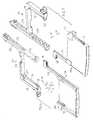
- FIG. 3is an exploded isometric view of the electronic device of FIGS. 1 and 2, including the top cover portion.
- FIG. 4is a plan view of the tray assembly of FIG. 1 in its deployed position.
- FIG. 5is a view similar to that of FIG. 4, showing a first side of the housing and showing the tray assembly in the stowed position.
- FIG. 6is an exploded isometric view of the tray assembly of FIG. 4, but without the spring.
- FIG. 7is an upside-down exploded isometric view of the tray assembly of FIG. 6 .
- FIG. 8is a partial sectional view taken on line 8 — 8 of FIG. 4 .
- FIG. 9is an enlarged view of a portion of the upside-down view of FIG. 7, showing the cam element of the double click mechanism thereof.
- FIG. 1illustrates an electronic device 10 which is a Type II IC card constructed in accordance with PCMCIA (Personal Computer Memory Card International Association standards) which specifies a maximum height in vertical directions U, D of 5 mm.
- the IC cardhas a tray assembly 12 with a tray 14 that can slide along a slot 16 , between the deployed position shown at 14 in FIG. 1, and the stowed position shown at 14 A in FIG. 2 .
- an electronic component 20which is a fingerprint sensor that lies on a rear portion of the tray, is exposed. A person lays his/her finger on the sensor which senses the person's fingerprint characteristics.
- the output of the fingerprint sensor component 20is delivered through an electrical connector arrangement 22 to a mother board 24 that is fixed to a housing 26 of the electronic device.
- the housinghas front and rear ends 27 , 28 spaced in longitudinal directions M and has laterally L opposite sides 146 .
- signals from the fingerprint sensor component 20are delivered (or processed data based on it is delivered) through a front connector 30 to another electronic device such as a computer.
- the trayWhen the tray is in the stowed position 14 A of FIG. 2, the tray can be moved to the deployed position by a person pushing forwardly against a rear surface 32 of the tray. A double click mechanism 34 then releases the tray so it can slide rearward, and a tension spring 36 moves the tray rearward to the deployed position.
- FIG. 3shows that the electronic device includes top and bottom cover portions 40 , 42 that form much of the housing 26 .
- the mother board 24which has top and bottom surfaces 44 , 46 , lies on the bottom cover portion and is fixed in place thereon. It is noted that in the particular device illustrated, the bottom cover portion has an opening 51 for receiving a SIM smart card 53 , and that a connector 55 mounted on the mother board has contacts that engage pads 57 on the SIM card.
- a computer that receives the IC card electronic device 10can be programmed to authorize usage if there is high correspondence between the fingerprint of the person and a stored fingerprint code, and also allow authorization if there is a lower correspondence but the person has a proper SIM card 53 .
- a tray guide 50is mounted in the housing, to provide much of the guiding of the tray, and to perform other functions.
- the tray guideincludes a largely U-shaped holder 52 with a base 54 and with a pair of legs 56 , 58 extending rearwardly R from opposite sides of the base.
- the tray 14has opposite sides that fit between the legs 56 , 58 of the holder.
- FIGS. 6 and 7show that the double click mechanism includes a cam element 70 and a cam follower element 72 .
- the cam elementis well known, and as shown in FIG. 9, includes a groove 74 and a divider 76 that divides the groove into two diverging portions 80 , 82 and a rear connecting groove portion 84 .
- the cam followerincludes a follower part 90 in the form of a pin that rides along the groove 74 .
- the first time that the tray 14 is pushed forward by pushing against the cam and tray rear surface 32the follower part 90 moves along one of the groove parts 82 .
- the springholds the follower part against a surface 92 .
- a second forward push against the cam rear surface 32results in the follower part 90 being diverted to the other groove part 80 , while allowing the tray to move a considerable distance such as 2 centimeters (cm) rearward R to its deployed position.
- the cam follower element 70is formed by molding it into a side 100 of the tray.
- FIG. 6shows that the cam element 72 , whose follower part 90 must move up and down, is formed by a longitudinally M elongated and vertically resilient beam.
- the beam of the cam follower elementhas a front end 102 molded integrally with the rest of the tray guide, near an intersection of the leg 58 with the base 54 .
- FIG. 3shows that the tray 14 has a second side 110 , and has a forwardly-projecting arm 112 that projects forwardly from the side 110 of the tray.
- the arm 112has a front end forming a front spring mount 114 .
- the tension spring 36has a front end 120 that is attached to the front spring mount.
- the tray guide 50has a rear spring mount 122 at the rear end of its leg 56 , and the spring has a rear end 124 that mounts on the rear spring mount 122 .
- FIG. 5shows the spring 36 fully expanded in length and held between the spring mount 114 on the tray and the spring mount 122 on the tray guide.
- the springtends to pull the tray 14 rearward R, but the engagement of the cam follower part 90 with the cam element 70 prevents such forward movement until the tray is pushed inward slightly, as by about 1 mm.
- the double click mechanism 34has released the tray to move rearward, the tray moves rearward to the deployed position 14 A of FIG. 4 .
- projections 121 at the front end of the trayabut a rear wall 192 of the housing.
- the spring mount 114(FIG. 7, which is upside-down) on the tray abuts another stop 124 .
- FIG. 6shows that the tray guide 50 has a forwardly-projecting arm-guide leg 128 with a slot or passage 130 , and that the spring mount 114 at the front of the spring arm 112 projects laterally L through the passage to project laterally from the right leg 56 .
- the passage 130helps to closely guide the spring arm 112 to prevent up or down deflection of the spring mount 114 under the tension force of the spring.
- the spring holder arm 112is wider in a lateral direction than its thickness in a vertical direction, so guidance by the walls of the passage 130 in the leg 128 is especially useful.
- eachincludes a sheet metal portion 140 , 142 and plastic side beams 144 , 145 at opposite sides of each portion, with the side beams 144 , 145 being sonically welded together to close the cover around the mother board and other parts.
- the side 146 of the housingis spaced from the tray guide first or rightmost leg 56 by a distance that is slightly wider than the diameter of the tension spring 36 .
- the springlies in an isolated area 150 between a housing side wall and a tray guide leg 56 .
- the isolated arealies on a side of the tray leg 56 opposite the space 148 that receives the tray. Since the spring is a moving part that can vibrate and that has numerous spring turns that can rub or catch against other parts, the confining to an isolated area, avoids damage to or from the spring.
- FIG. 3shows that the fingerprint sensor component 20 is mounted on a daughter board 160 , and that a ribbon or flexible cable connector 162 is mounted on the daughter board.
- Another flexible cable connector 164is mounted on the mother board.
- a ribbon cable or flat flexible cable 166extends between the two connectors 162 , 164 .
- the flat flexible cable 166has upper and lower cable parts 170 , 172 that each lies in substantially a horizontal plane (that is normal to the vertical directions U, D) and that are connected by a substantially 180° bend 174 .
- the bent cable portionis bent about a horizontal axis 176 that extends laterally L.
- the upper cable part 170grows in length while the lower cable part shortens in length, but they always remain largely planar.
- the flat flexible cablehas very thin conductors, so the bend 174 can have a small height such as 2 mm without being permanently deformed. If the bottom cover portion does not have a slot for receiving a SIM card, a slot indicated at 180 can be formed in the mother board to provide for a larger radius of curvature at the bend 174 . It is noted that for a fingerprint component 20 , the component has numerous surface mount contacts at its lower end that are soldered to traces on the daughter board 160 , with the traces extending to the daughter board cable connector 162 .
- FIG. 3shows that the base 54 of the tray guide has a slot 184 through which the flat flexible cable extends. This allows the rest of the base to extend up against the sheet metal portion 140 of the top cover portion for maximum thickness of the tray guide (except at the slot) and to help support the sheet metal portion.
- the tray guide 50is preferably mounted directly to the housing 26 of the electronic device.
- the tray guidehas a rear end that includes a lateral side extension 190 (FIG. 1) that extends the tray rear end across the entire width of the device between its housing opposite sides 146 , thereby trapping the rear of the tray guide.
- a separate rear wall 192 of the housinghas a lug 194 that fits into a corresponding recess at the extension 190 on the tray guide, and these parts can be locked together.
- the forwardly-elongated arm guide leg 56 of the tray guidehas an extension 200 that receives a lug 202 projecting inwardly from the housing side 146 .
- FIG. 5shows that the slots 210 , 212 are slightly undercut and the lugs have corresponding enlarged ends. This allows the lugs 194 , 202 to lock to the housing by merely pressing down the tray guide into the bottom cover portion.
- the electronic device 10 shown in FIG. 1is assembled by first assembling the tray 14 to the tray guide 50 and then moving the tray guide down into the bottom cover portion 42 until the tray guide locks to the lugs 194 , 202 . Then, the mother board 24 is slid rearwardly into place around the tray guide.
- the flat flexible cable 166will already have been attached to one of the connectors such as the one on the mother board, and is then attached to the other connector such as the one 162 on the daughter board.
- the forward connector 164may already be soldered to the mother board and settles into place as the mother board is installed.
- the top cover portion 40is placed over the bottom cover portion and the plastic parts at the sides 144 , 146 and at portions of the front and rear ends are ultrasonically welded together.
- FIG. 8shows that the tray 14 is guided against vertical movement by the sheet metal walls 140 , 142 of the top and bottom cover portions that engage opposite sides 100 , 110 of the tray.
- the right side 110 of the trayis guided in a tongue 220 and groove 222 sliding connection.
- the left sideis guided only by abutment of the tray left side 100 at projections 121 that lie above and below the cam follower element 72 .
- a tongue-and-groove jointcannot be readily provided on the left side because of the follower element 72 .
- the tongue-and-groove connection at the right side 110 of the trayhelps prevent the tray from deflecting downward in its deployed position.
- the traycan extend from any wall of the electronic device, which wall can be considered to be a rear part.
- the inventionprovides an electronic device with a tray assembly that includes a tray that can move rearward and forward between a stowed position and a deployed position, in an easily installed, easily operated, and rugged construction.
- the tray assemblyincludes a spring that urges the tray rearwardly towards its deployed position, and a double click mechanism that latches the tray in the stowed position while releasing it when the tray is pushed forward slightly.
- the double click mechanismincludes a cam element and a cam follower element in the form of an elongated beam that can deflect, where one element is formed integrally with a polymer tray and the other element is formed integrally with a polymer molded tray guide that guides the tray in sliding movement.
- the spring that urges the tray rearwardis a tension spring with a spring forward end connected to a forwardly-projecting arm on the tray, and with a spring rear end mounted on the tray guide.
- the springcan be enclosed in an isolated area lying between one side of the housing and a side of the tray guide.
- a daughter board on the trayis connected to a mother board lying in a fixed position on the housing, by a flat flexible cable with horizontal upper and lower cable portions that are connected by a substantially 180° bend in the cable. Instead, contacts on the underside of the daughterboard could slide into engagement with contacts of a connector on the motherboard.
- the tray guidecan be mounted by forming it with laterally spaced undercut slots that closely receive lugs formed in plastic beams of the housing.
Landscapes
- Engineering & Computer Science (AREA)
- Computer Hardware Design (AREA)
- Microelectronics & Electronic Packaging (AREA)
- Physics & Mathematics (AREA)
- General Physics & Mathematics (AREA)
- Theoretical Computer Science (AREA)
- Automation & Control Theory (AREA)
- Coupling Device And Connection With Printed Circuit (AREA)
Abstract
Description
Retractable trays have been incorporated in several types of electronic devices, such as IC cards, cell phones and PDA (personal digital assistants). The retractable tray holds a component such as a fingerprint sensor or telephone jack connector that is concealed and protected when the tray is stowed, and easily accessible when the tray is deployed. The tray can be deployed from its stowed position by pulling out the tray or moving an actuator along the slot, etc., but it is often difficult to grasp the tray to pull it or to operate an actuator. Automatic deployment devices such as a double click mechanism that pushes out the tray when the tray is pushed in a second time, is generally desirable. However, such mechanism has required additional parts which increase the complexity of the tray assembly. When the tray must be contained within an electronic device of very small height, such as a Type II PCMCIA standard IC card, which has a maximum thickness of 5 mm (millimeters), this can lead to a mechanism that is expensive to make and assemble and which is easily broken. A tray assembly for an electronic device, which had a minimum number of parts, which was rugged, and which enabled easy tray deployment as with a double click mechanism, would be of value.
In accordance with one embodiment of the present invention, an electronic device is provided with a tray assembly that includes a tray that holds a component to move it into the housing of the electronic device when the tray is stowed, and to move it out of the electronic device when the tray is deployed, which is of simple and rugged design. The tray assembly includes a tray guide mounted on the housing and on which the tray can slide. A spring coupled to the tray urges it rearwardly towards the deployed position. A double click mechanism is provided that includes a cam element and a follower element, one mounted on the tray and the other on the tray guide. The double click mechanism latches the tray in the stowed position until it is pushed forward slightly, when it is released to move rearwardly to the deployed position. The tray and tray guide are each molded polymer parts, with one of the elements of the click mechanism molded integrally with the tray and the other element molded integrally with the tray guide. This minimizes the number of parts to be made and mounted.
The tray has a groove that forms the cam follower. The tray guide includes a largely U-shaped part with a base and a pair of legs extending rearwardly from the base, with the tray slideably mounted between the two legs. The cam follower is formed by a resilient arm extending rearwardly from the base of the tray guide and having a cam follower part at its rear end which is engaged in the groove of the cam.
The tray has a forwardly-projecting spring arm. A tension spring has a front end mounted on the front end of the spring arm, and has a spring rear end mounted on the rear end of a leg of the tray guide. The use of a tension spring avoids the problem of column collapse of a compression spring. The tension spring lies in a confined area between a side of the tray guide and a side of the housing of the electronic device.
An electronic connecting arrangement that connects the component on a moving tray to a mother board on the stationary housing, includes a flat flexible cable having upper and lower cable parts lying in horizontal planes and connected by a 180° bend.
The novel features of the invention are set forth with particularity in the appended claims. The invention will be best understood from the following description when read in conjunction with the accompanying drawings.
FIG. 1 is a rear and top isometric view of an electronic device of the invention, with the top cover portion removed, and with the tray in a deployed position.
FIG. 2 is a view similar to that of FIG. 1, but with the tray in a stowed position.
FIG. 3 is an exploded isometric view of the electronic device of FIGS. 1 and 2, including the top cover portion.
FIG. 4 is a plan view of the tray assembly of FIG. 1 in its deployed position.
FIG. 5 is a view similar to that of FIG. 4, showing a first side of the housing and showing the tray assembly in the stowed position.
FIG. 6 is an exploded isometric view of the tray assembly of FIG. 4, but without the spring.
FIG. 7 is an upside-down exploded isometric view of the tray assembly of FIG.6.
FIG. 8 is a partial sectional view taken on line8—8 of FIG.4.
FIG. 9 is an enlarged view of a portion of the upside-down view of FIG. 7, showing the cam element of the double click mechanism thereof.
FIG. 1 illustrates anelectronic device 10 which is a Type II IC card constructed in accordance with PCMCIA (Personal Computer Memory Card International Association standards) which specifies a maximum height in vertical directions U, D of 5 mm. The IC card has atray assembly 12 with atray 14 that can slide along aslot 16, between the deployed position shown at14 in FIG. 1, and the stowed position shown at14A in FIG.2. In the deployed position of FIG. 1, anelectronic component 20 which is a fingerprint sensor that lies on a rear portion of the tray, is exposed. A person lays his/her finger on the sensor which senses the person's fingerprint characteristics. The output of thefingerprint sensor component 20 is delivered through anelectrical connector arrangement 22 to amother board 24 that is fixed to ahousing 26 of the electronic device. The housing has front andrear ends opposite sides 146. For an IC card electronic device, signals from thefingerprint sensor component 20 are delivered (or processed data based on it is delivered) through afront connector 30 to another electronic device such as a computer.
When the tray is in thestowed position 14A of FIG. 2, the tray can be moved to the deployed position by a person pushing forwardly against arear surface 32 of the tray. Adouble click mechanism 34 then releases the tray so it can slide rearward, and atension spring 36 moves the tray rearward to the deployed position.
FIG. 3 shows that the electronic device includes top andbottom cover portions housing 26. Themother board 24, which has top andbottom surfaces opening 51 for receiving a SIMsmart card 53, and that aconnector 55 mounted on the mother board has contacts that engagepads 57 on the SIM card. A computer that receives the IC cardelectronic device 10 can be programmed to authorize usage if there is high correspondence between the fingerprint of the person and a stored fingerprint code, and also allow authorization if there is a lower correspondence but the person has aproper SIM card 53.
Atray guide 50 is mounted in the housing, to provide much of the guiding of the tray, and to perform other functions. The tray guide includes a largely U-shapedholder 52 with abase 54 and with a pair oflegs tray 14 has opposite sides that fit between thelegs
FIGS. 6 and 7 show that the double click mechanism includes acam element 70 and acam follower element 72. The cam element is well known, and as shown in FIG. 9, includes agroove 74 and adivider 76 that divides the groove into two divergingportions 80,82 and a rear connectinggroove portion 84. The cam follower includes afollower part 90 in the form of a pin that rides along thegroove 74. The first time that thetray 14 is pushed forward by pushing against the cam and trayrear surface 32, thefollower part 90 moves along one of the groove parts82. When the tray is no longer pushed forward, the spring holds the follower part against asurface 92. A second forward push against the camrear surface 32 results in thefollower part 90 being diverted to theother groove part 80, while allowing the tray to move a considerable distance such as 2 centimeters (cm) rearward R to its deployed position.
Thecam follower element 70 is formed by molding it into aside 100 of the tray. FIG. 6 shows that thecam element 72, whosefollower part 90 must move up and down, is formed by a longitudinally M elongated and vertically resilient beam. The beam of the cam follower element has afront end 102 molded integrally with the rest of the tray guide, near an intersection of theleg 58 with thebase 54. By forming thefollower element 72 as an integral part of the tray guide, applicant avoids the need for a separate follower element and for means for pivotally mounting the follower element on the housing or tray guide.
FIG. 3 shows that thetray 14 has asecond side 110, and has a forwardly-projectingarm 112 that projects forwardly from theside 110 of the tray. Thearm 112 has a front end forming afront spring mount 114. Thetension spring 36 has afront end 120 that is attached to the front spring mount. Thetray guide 50 has arear spring mount 122 at the rear end of itsleg 56, and the spring has arear end 124 that mounts on therear spring mount 122. FIG. 5 shows thespring 36 fully expanded in length and held between thespring mount 114 on the tray and thespring mount 122 on the tray guide. The spring tends to pull thetray 14 rearward R, but the engagement of thecam follower part 90 with thecam element 70 prevents such forward movement until the tray is pushed inward slightly, as by about 1 mm. After the tray has been pushed forward slightly, so thedouble click mechanism 34 has released the tray to move rearward, the tray moves rearward to the deployedposition 14A of FIG.4. As shown in FIG. 1, when the tray reaches its deployed position,projections 121 at the front end of the tray abut arear wall 192 of the housing. At the same time, the spring mount114 (FIG. 7, which is upside-down) on the tray abuts anotherstop 124.
FIG. 6 shows that thetray guide 50 has a forwardly-projecting arm-guide leg 128 with a slot orpassage 130, and that thespring mount 114 at the front of thespring arm 112 projects laterally L through the passage to project laterally from theright leg 56. Thepassage 130 helps to closely guide thespring arm 112 to prevent up or down deflection of thespring mount 114 under the tension force of the spring. Thespring holder arm 112 is wider in a lateral direction than its thickness in a vertical direction, so guidance by the walls of thepassage 130 in theleg 128 is especially useful.
The top and bottom cover portions shown in FIG. 3 at40 and42, each includes asheet metal portion side 146 of the housing is spaced from the tray guide first orrightmost leg 56 by a distance that is slightly wider than the diameter of thetension spring 36. As a result, the spring lies in anisolated area 150 between a housing side wall and atray guide leg 56. The isolated area lies on a side of thetray leg 56 opposite thespace 148 that receives the tray. Since the spring is a moving part that can vibrate and that has numerous spring turns that can rub or catch against other parts, the confining to an isolated area, avoids damage to or from the spring.
FIG. 3 shows that thefingerprint sensor component 20 is mounted on adaughter board 160, and that a ribbon orflexible cable connector 162 is mounted on the daughter board. Anotherflexible cable connector 164 is mounted on the mother board. A ribbon cable or flatflexible cable 166 extends between the twoconnectors flexible cable 166 has upper andlower cable parts bend 174. As shown in FIGS. 1 and 2, the bent cable portion is bent about ahorizontal axis 176 that extends laterally L. When the tray is deployed, theupper cable part 170 grows in length while the lower cable part shortens in length, but they always remain largely planar. The flat flexible cable has very thin conductors, so thebend 174 can have a small height such as 2 mm without being permanently deformed. If the bottom cover portion does not have a slot for receiving a SIM card, a slot indicated at180 can be formed in the mother board to provide for a larger radius of curvature at thebend 174. It is noted that for afingerprint component 20, the component has numerous surface mount contacts at its lower end that are soldered to traces on thedaughter board 160, with the traces extending to the daughterboard cable connector 162.
FIG. 3 shows that thebase 54 of the tray guide has aslot 184 through which the flat flexible cable extends. This allows the rest of the base to extend up against thesheet metal portion 140 of the top cover portion for maximum thickness of the tray guide (except at the slot) and to help support the sheet metal portion.
Thetray guide 50 is preferably mounted directly to thehousing 26 of the electronic device. The tray guide has a rear end that includes a lateral side extension190 (FIG. 1) that extends the tray rear end across the entire width of the device between its housing oppositesides 146, thereby trapping the rear of the tray guide. A separaterear wall 192 of the housing has alug 194 that fits into a corresponding recess at theextension 190 on the tray guide, and these parts can be locked together. Similarly, the forwardly-elongatedarm guide leg 56 of the tray guide has anextension 200 that receives alug 202 projecting inwardly from thehousing side 146. FIG. 5 shows that theslots lugs
Theelectronic device 10 shown in FIG. 1 is assembled by first assembling thetray 14 to thetray guide 50 and then moving the tray guide down into thebottom cover portion 42 until the tray guide locks to thelugs mother board 24 is slid rearwardly into place around the tray guide. The flatflexible cable 166 will already have been attached to one of the connectors such as the one on the mother board, and is then attached to the other connector such as the one162 on the daughter board. Theforward connector 164 may already be soldered to the mother board and settles into place as the mother board is installed. Finally, thetop cover portion 40 is placed over the bottom cover portion and the plastic parts at thesides
FIG. 8 shows that thetray 14 is guided against vertical movement by thesheet metal walls opposite sides right side 110 of the tray is guided in atongue 220 and groove222 sliding connection. The left side is guided only by abutment of the tray leftside 100 atprojections 121 that lie above and below thecam follower element 72. A tongue-and-groove joint cannot be readily provided on the left side because of thefollower element 72. The tongue-and-groove connection at theright side 110 of the tray helps prevent the tray from deflecting downward in its deployed position.
While terms such as “upper”, “lower”, etc. have been used to describe the invention as it is illustrated, it should be understood that the electronic device and its parts can be used in any orientation with respect to the Earth. Also, the tray can extend from any wall of the electronic device, which wall can be considered to be a rear part.
Thus, the invention provides an electronic device with a tray assembly that includes a tray that can move rearward and forward between a stowed position and a deployed position, in an easily installed, easily operated, and rugged construction. The tray assembly includes a spring that urges the tray rearwardly towards its deployed position, and a double click mechanism that latches the tray in the stowed position while releasing it when the tray is pushed forward slightly. The double click mechanism includes a cam element and a cam follower element in the form of an elongated beam that can deflect, where one element is formed integrally with a polymer tray and the other element is formed integrally with a polymer molded tray guide that guides the tray in sliding movement. The spring that urges the tray rearward is a tension spring with a spring forward end connected to a forwardly-projecting arm on the tray, and with a spring rear end mounted on the tray guide. The spring can be enclosed in an isolated area lying between one side of the housing and a side of the tray guide. A daughter board on the tray is connected to a mother board lying in a fixed position on the housing, by a flat flexible cable with horizontal upper and lower cable portions that are connected by a substantially 180° bend in the cable. Instead, contacts on the underside of the daughterboard could slide into engagement with contacts of a connector on the motherboard. The tray guide can be mounted by forming it with laterally spaced undercut slots that closely receive lugs formed in plastic beams of the housing.
Although particular embodiments of the invention have been described and illustrated herein, it is recognized that modifications and variations may readily occur to those skilled in the art, and consequently, it is intended that the claims be interpreted to cover such modifications and equivalents.
Claims (15)
1. An electronic device that includes a mother board having top and bottom surfaces and front and rear ends, and a housing which includes top and bottom cover portions that lie respectively above and below said mother board and that are mechanically connected to said mother board, said housing having longitudinally-spaced front and rear ends and laterally spaced opposite sides, comprising:
a tray guide mounted on said housing;
a tray which is moveably mounted on said tray guide so said tray can move forward and rearward between a stowed position and a deployed position;
an electronic component mounted on said tray, with said component lying rearward of said housing rear end in said deployed position of said tray and lying within said housing in said stowed position of said tray;
a connecting arrangement that electronically couples said tray to said mother board at least when said tray is in said deployed position;
a spring that is coupled to said tray and that urges said tray rearwardly toward said deployed position;
a double click mechanism that includes a cam element and a follower element, which latches said tray in said stowed position when said tray is pushed forward from said deployed position to said stowed position and which releases said tray from said stowed position when said tray is pushed slightly forward therefrom, said double clock mechanism including a cam element and a follower element where one element is mounted on said tray and the other is mounted on said tray guide;
said tray and said tray guide are each molded polymer parts, with one of said elements of said click mechanism molded integrally with said tray and the other element of said click mechanism molded integrally with said tray guide.
2. The device described in claim1 wherein:
said tray guide includes a largely U-shaped part with a base having laterally opposite sides and a pair of legs extending rearwardly from said opposite sides, and with said follower element being in the form of a bendable beam having a front end merging with said U-shaped part at a location near the intersection of the front end of a second one of said legs and said base, with follower element extending rearwardly from said location and having a rear end with a laterally extending follower part that engages said cam element;
said tray has opposite sides with a second of said sides having a groove that forms cam element, with said follower part of said follower element projecting into said groove.
3. The device described in claim1 wherein:
said tray guide has laterally opposite sides and has a spring mount at one of said sides;
said tray has a component holder with laterally opposite sides, and has a spring holder arm that extends forwardly from one of said component holder sides and that has a holder arm front end;
a tension spring having a front end mounted on said holder arm front end, said spring having a rear end mounted on said spring mount.
4. The device described in claim1 wherein:
said connecting arrangement includes a flat flexible cable having upper and lower cable parts that each lies substantially in a horizontal plane, with said upper and lower cable parts joined by a substantially 180° bend in said cable about a laterally-extending axis, and with one of said cable parts connected to said tray to connect to said component and with the other of said cable parts connected to said mother board.
5. The device described in claim1 wherein:
said tray guide has laterally-spaced locations with projecting lugs, and said housing has a pair of slots that each receives one of said lugs, with said slots being undercut and said lugs matching said slots to lock to said housing at said locations.
6. The device described in claim2 wherein:
said tray has a first side lying opposite said second side and forming a first one of said legs with a longitudinally extending slot having top and bottom slot walls that lie closely above and below said tray second side to form a tongue-and-groove sliding connection at said first side of said tray.
7. The device described in claim2 wherein:
said tray guide has a second side with a second of said legs lying at said tray guide second side;
said tray has top and bottom projections that extend respectively above and below said beam formed by said follower element and that slideably engage said second leg of said tray guide.
8. The device described in claim4 wherein:
said tray guide has a largely U-shaped part with longitudinally extending legs having leg front ends and a base connecting said leg front ends;
said base has a slot and said cable extends through said slot.
9. An electronic device that includes a mother board having top and bottom surface and front and rear ends, and a housing which includes top and bottom cover portions that lie respectively above and below said mother board, said housing having longitudinally-spaced front and rear ends and laterally opposite sides, comprising:
a tray guide mounted on said housing and having a tray-receiving space and a first leg on one side of said space;
a tray which is slideably mounted on said tray guide to slide in said space, in forward and rearward directions between a stowed position and a deployed position;
said tray has a forwardly-projecting arm with a front end forming a front spring mount lying on a side of said first leg of said tray guide that is opposite said tray-receiving space;
said first leg of said tray guide has a rear spring mount lying directly rearward of said front spring mount;
a tension spring having a front end mounted on said front spring mount of said tray arm, and having a rear end mounted on said rear spring mount.
10. The device described in claim9 wherein:
said tray guide has an arm-guide leg projecting forwardly from said first leg, with said tray guide having a longitudinally-extending passage;
said first spring mount on said forwardly-projecting arm of said tray, projects laterally through said passage.
11. The device described in claim9 wherein:
said housing has laterally opposite sides, and said spring lies between said tray guide first leg and a first of said sides of said housing, and said spring is vertically enclosed between said top and bottom cover portions.
12. The device described in claim11 including:
a tray guide mounted on said housing, with said tray slideably mounted on said tray guide, said tray guide including a U-shaped part with a base and laterally opposite legs that extend rearwardly from said base, with said base having an upper end with a slot and with said upper cable part extending through said slot.
13. An electronic device that includes a mother board having top and bottom surfaces and front and rear ends, and a housing which includes top and bottom cover parts that lie respectively above and below said mother board, said housing having front and rear ends and laterally spaced opposite sides, comprising:
a tray which is moveably mounted in said card housing to move forward and rearward respectively between a stowed position and a deployed position;
an electronic component mounted on said tray with said component lying rearward of said housing rear end in said deployed position of said tray and lying within said housing in said stowed position of said tray;
a connecting arrangement that electronically couples said component to said mother board at least when said tray is in said deployed position;
said connecting arrangement includes a flat flexible cable having upper and lower cable parts that each lies substantially in a horizontal plane, with said upper and lower cable parts joined by a substantially 180° bend in said cable about a laterally-extending axis, and with one of said cable parts connected to said tray to connect to said component and with the other of said cable parts connected to said mother board.
14. The device described in claim13 including:
a tray guide mounted on said housing, with said tray slideably mounted on said tray guide;
a tray cable connector mounted on said tray and a board cable connector mounted on said mother board, with said upper cable part having a rear end connected to said tray connector and with said lower cable part having a rear end connected to said board connector, and with said 180° bend lying forward of both of said connectors.
15. An electronic device that includes a mother board having top and bottom surfaces and front and rear ends, and a housing which includes top and bottom cover portions that lie respectively above and below said mother board and that are mechanically connected to said mother board, said card housing having longitudinally-spaced front and rear end walls and laterally spaced opposite side walls, comprising:
a tray guide mounted on said housing;
a tray which is moveably mounted on said tray guide so said tray can move forward and rearward between a stowed position and a deployed position;
an electronic component mounted on said tray, with said component lying rearward of said housing rear end in said deployed position of said tray and lying within said housing in said stowed position of said tray;
a connecting arrangement that electronically couples said tray to said mother board at least when said tray is in said deployed position;
said housing has at least a pair of laterally-spaced lugs that each projects into said housing from one of said walls of said housing;
said tray guide has opposite sides, with each side having a slot that closely receives one of said lugs, with each slot being undercut and each lug having a corresponding shape to lock to the slot.
Priority Applications (5)
| Application Number | Priority Date | Filing Date | Title |
|---|---|---|---|
| US09/583,163US6330151B1 (en) | 2000-05-30 | 2000-05-30 | Electronic device with retractable tray |
| AT00115968TATE330293T1 (en) | 1999-09-10 | 2000-07-26 | IC CARD WITH EXTENDABLE TRAY |
| DE60028674TDE60028674T2 (en) | 1999-09-10 | 2000-07-26 | IC card with pull-out shelf |
| EP00115968AEP1083518B1 (en) | 1999-09-10 | 2000-07-26 | IC card with retractable tray |
| HK01106500.9AHK1037760B (en) | 1999-09-10 | 2001-09-14 | Ic card with retractable tray |
Applications Claiming Priority (1)
| Application Number | Priority Date | Filing Date | Title |
|---|---|---|---|
| US09/583,163US6330151B1 (en) | 2000-05-30 | 2000-05-30 | Electronic device with retractable tray |
Publications (1)
| Publication Number | Publication Date |
|---|---|
| US6330151B1true US6330151B1 (en) | 2001-12-11 |
Family
ID=24331935
Family Applications (1)
| Application Number | Title | Priority Date | Filing Date |
|---|---|---|---|
| US09/583,163Expired - LifetimeUS6330151B1 (en) | 1999-09-10 | 2000-05-30 | Electronic device with retractable tray |
Country Status (1)
| Country | Link |
|---|---|
| US (1) | US6330151B1 (en) |
Cited By (20)
| Publication number | Priority date | Publication date | Assignee | Title |
|---|---|---|---|---|
| US6518927B2 (en)* | 2000-08-05 | 2003-02-11 | Itt Manufacturing Enterprises, Inc. | PC card for electronic devices |
| US6551131B1 (en)* | 2001-12-17 | 2003-04-22 | Hon Hai Precision Ind. Co., Ltd. | Stacked electrical card connector assembly |
| US6570767B1 (en)* | 1999-08-10 | 2003-05-27 | Nokia Mobile Phones Ltd. | Card adapter |
| US20040066954A1 (en)* | 1999-08-18 | 2004-04-08 | Fujitsu Limited | Extension device providing security function |
| US20040218416A1 (en)* | 2001-09-20 | 2004-11-04 | Hiromasa Yamagishi | Recording or reproducing apparatus to which recording medium is detachably attached |
| US20050230484A1 (en)* | 2004-04-16 | 2005-10-20 | Cuellar Edwin J | Memory cards having two standard sets of contacts |
| US20050230483A1 (en)* | 2004-04-16 | 2005-10-20 | Miller Robert C | Memory card with two standard sets of contacts and a contact covering mechanism |
| US20060126287A1 (en)* | 2004-12-10 | 2006-06-15 | Fih Co., Ltd | Stylus removal mechanism |
| US7092256B1 (en)* | 2002-04-26 | 2006-08-15 | Sandisk Corporation | Retractable card adapter |
| US20070087725A1 (en)* | 2005-10-19 | 2007-04-19 | David Anderson | Apparatus, system, and method for secure storage bay for an electronic handheld device |
| US20070223179A1 (en)* | 2006-03-27 | 2007-09-27 | Shi Ming Cheng | Fingerprint recognition smart card |
| US20070275758A1 (en)* | 2003-11-28 | 2007-11-29 | Nokia Corporation | Mobile Telephone and a Method of Operating the Mobile Telephone |
| US20080030963A1 (en)* | 2005-08-02 | 2008-02-07 | Warren Middlekauff | Memory Card With Latching Mechanism for Hinged Cover |
| US20100039786A1 (en)* | 2008-08-13 | 2010-02-18 | Shenzhen Huawei Communication Technologies Co., Ltd. | Communication device |
| US20110255252A1 (en)* | 2010-04-19 | 2011-10-20 | Apple Inc. | Compact ejectable component assemblies in electronic devices |
| US20110312270A1 (en)* | 2010-06-22 | 2011-12-22 | At&T Mobility Ii Llc | Near Field Communication Adapters |
| US20130250524A1 (en)* | 2012-03-20 | 2013-09-26 | Brocade Communications Systems, Inc. | Compact Flash Retainer |
| US9819105B2 (en)* | 2016-01-19 | 2017-11-14 | Foxconn Interconnect Technology Limited | Card connector assembly having a card tray with a latch |
| US10957968B2 (en)* | 2018-11-20 | 2021-03-23 | Motorola Mobility Llc | Deployable and retractable antenna array module |
| US11637437B2 (en)* | 2019-04-17 | 2023-04-25 | Masimo Corporation | Charging station for physiological monitoring device |
Citations (15)
| Publication number | Priority date | Publication date | Assignee | Title |
|---|---|---|---|---|
| US4582985A (en) | 1981-03-18 | 1986-04-15 | Loefberg Bo | Data carrier |
| US5180901A (en) | 1990-05-21 | 1993-01-19 | Kabushiki Kaisha Toshiba | IC card with individual authentication function |
| US5183404A (en) | 1992-04-08 | 1993-02-02 | Megahertz Corporation | Systems for connection of physical/electrical media connectors to computer communications cards |
| US5411405A (en) | 1993-11-12 | 1995-05-02 | Angia Communications, Inc. | Miniature electrical communications connectors |
| US5463261A (en) | 1994-10-19 | 1995-10-31 | Minnesota Mining And Manufacturing Company | Power conservation device for a peripheral interface module |
| US5547401A (en) | 1992-04-08 | 1996-08-20 | Megahertz Corporation | Media connector interface for use with a thin-architecture communications card |
| US5623552A (en) | 1994-01-21 | 1997-04-22 | Cardguard International, Inc. | Self-authenticating identification card with fingerprint identification |
| US5773332A (en) | 1993-11-12 | 1998-06-30 | Xircom, Inc. | Adaptable communications connectors |
| US5815252A (en) | 1995-09-05 | 1998-09-29 | Canon Kabushiki Kaisha | Biometric identification process and system utilizing multiple parameters scans for reduction of false negatives |
| US5971777A (en) | 1997-11-21 | 1999-10-26 | 3Com Corporation | Breakaway physical/electrical media jack |
| US5975927A (en) | 1992-04-08 | 1999-11-02 | 3Com Corporation | Communications card having rotating communications port |
| US5989042A (en) | 1998-04-03 | 1999-11-23 | 23-3178 | Electrical connector for use between shielded media connectors and computer communications cards |
| US6000957A (en) | 1997-12-29 | 1999-12-14 | Itt Manufacturing Enterprises, Inc. | PC card extendable interface |
| US6012636A (en) | 1997-04-22 | 2000-01-11 | Smith; Frank E. | Multiple card data system having first and second memory elements including magnetic strip and fingerprints scanning means |
| US6101088A (en)* | 1993-09-09 | 2000-08-08 | Kabushiki Kaisha Toshiba | Portable electronic apparatus having a frame supporting functional components |
- 2000
- 2000-05-30USUS09/583,163patent/US6330151B1/ennot_activeExpired - Lifetime
Patent Citations (18)
| Publication number | Priority date | Publication date | Assignee | Title |
|---|---|---|---|---|
| US4582985A (en) | 1981-03-18 | 1986-04-15 | Loefberg Bo | Data carrier |
| US5180901A (en) | 1990-05-21 | 1993-01-19 | Kabushiki Kaisha Toshiba | IC card with individual authentication function |
| US5975927A (en) | 1992-04-08 | 1999-11-02 | 3Com Corporation | Communications card having rotating communications port |
| US5183404A (en) | 1992-04-08 | 1993-02-02 | Megahertz Corporation | Systems for connection of physical/electrical media connectors to computer communications cards |
| US5336099A (en) | 1992-04-08 | 1994-08-09 | Megahertz Corporation | Media connector interface for use with a PCMCIA-architecture communications card |
| US5338210A (en) | 1992-04-08 | 1994-08-16 | Megahertz Corporation | Media connector interface for use with a PCMCIA-architecture communications card |
| US5547401A (en) | 1992-04-08 | 1996-08-20 | Megahertz Corporation | Media connector interface for use with a thin-architecture communications card |
| US5727972A (en) | 1992-04-08 | 1998-03-17 | Aldous; Stephen C. | Media connector interface for use with a thin-architecture communications card |
| US6101088A (en)* | 1993-09-09 | 2000-08-08 | Kabushiki Kaisha Toshiba | Portable electronic apparatus having a frame supporting functional components |
| US5411405A (en) | 1993-11-12 | 1995-05-02 | Angia Communications, Inc. | Miniature electrical communications connectors |
| US5773332A (en) | 1993-11-12 | 1998-06-30 | Xircom, Inc. | Adaptable communications connectors |
| US5623552A (en) | 1994-01-21 | 1997-04-22 | Cardguard International, Inc. | Self-authenticating identification card with fingerprint identification |
| US5463261A (en) | 1994-10-19 | 1995-10-31 | Minnesota Mining And Manufacturing Company | Power conservation device for a peripheral interface module |
| US5815252A (en) | 1995-09-05 | 1998-09-29 | Canon Kabushiki Kaisha | Biometric identification process and system utilizing multiple parameters scans for reduction of false negatives |
| US6012636A (en) | 1997-04-22 | 2000-01-11 | Smith; Frank E. | Multiple card data system having first and second memory elements including magnetic strip and fingerprints scanning means |
| US5971777A (en) | 1997-11-21 | 1999-10-26 | 3Com Corporation | Breakaway physical/electrical media jack |
| US6000957A (en) | 1997-12-29 | 1999-12-14 | Itt Manufacturing Enterprises, Inc. | PC card extendable interface |
| US5989042A (en) | 1998-04-03 | 1999-11-23 | 23-3178 | Electrical connector for use between shielded media connectors and computer communications cards |
Cited By (56)
| Publication number | Priority date | Publication date | Assignee | Title |
|---|---|---|---|---|
| US6570767B1 (en)* | 1999-08-10 | 2003-05-27 | Nokia Mobile Phones Ltd. | Card adapter |
| US7010145B1 (en)* | 1999-08-18 | 2006-03-07 | Fujitsu Limited | Extension device providing security function |
| US7110574B2 (en)* | 1999-08-18 | 2006-09-19 | Fujitsu Limited | Extension device providing security function |
| US20040066954A1 (en)* | 1999-08-18 | 2004-04-08 | Fujitsu Limited | Extension device providing security function |
| US6518927B2 (en)* | 2000-08-05 | 2003-02-11 | Itt Manufacturing Enterprises, Inc. | PC card for electronic devices |
| US20040218416A1 (en)* | 2001-09-20 | 2004-11-04 | Hiromasa Yamagishi | Recording or reproducing apparatus to which recording medium is detachably attached |
| US7281253B2 (en)* | 2001-09-20 | 2007-10-09 | Sanyo Electric Co., Ltd. | Recording or reproducing apparatus to which recording medium is detachably attached |
| US6551131B1 (en)* | 2001-12-17 | 2003-04-22 | Hon Hai Precision Ind. Co., Ltd. | Stacked electrical card connector assembly |
| US7787243B2 (en) | 2002-04-26 | 2010-08-31 | Sandisk Corporation | Retractable card adapter |
| US20090201638A1 (en)* | 2002-04-26 | 2009-08-13 | Salazar Jeffrey A | Retractable card adapter |
| US7492601B2 (en) | 2002-04-26 | 2009-02-17 | Sandisk Corporation | Retractable card adapter |
| US7092256B1 (en)* | 2002-04-26 | 2006-08-15 | Sandisk Corporation | Retractable card adapter |
| US20070274117A1 (en)* | 2002-04-26 | 2007-11-29 | Salazar Jeffrey A | Retractable card adapter |
| US20070275758A1 (en)* | 2003-11-28 | 2007-11-29 | Nokia Corporation | Mobile Telephone and a Method of Operating the Mobile Telephone |
| US20080191033A1 (en)* | 2004-04-16 | 2008-08-14 | Cuellar Edwin J | Memory Cards Having Two Standard Sets Of Contacts |
| US7340540B2 (en) | 2004-04-16 | 2008-03-04 | Sandisk Corporation | Memory card with contacts, device connector, and a connector covering mechanism |
| US20070099511A1 (en)* | 2004-04-16 | 2007-05-03 | Miller Robert C | Memory Card With Two Standard Sets of Contacts and a Contact Covering Mechanism |
| US7822883B2 (en) | 2004-04-16 | 2010-10-26 | Sandisk Corporation | Memory card with two standard sets of contacts and a hinged contact covering mechanism |
| US20070032101A1 (en)* | 2004-04-16 | 2007-02-08 | Cuellar Edwin J | Memory Cards Having Two Standard Sets of Contacts |
| US7152801B2 (en) | 2004-04-16 | 2006-12-26 | Sandisk Corporation | Memory cards having two standard sets of contacts |
| US20060282553A1 (en)* | 2004-04-16 | 2006-12-14 | Miller Robert C | Memory Card With Two Standard Sets of Contacts and a Contact Covering Mechanism |
| US7310692B2 (en) | 2004-04-16 | 2007-12-18 | Sandisk Corporation | Memory card with integral covered second device connector for use with computing devices without a memory card slot |
| US20050230484A1 (en)* | 2004-04-16 | 2005-10-20 | Cuellar Edwin J | Memory cards having two standard sets of contacts |
| US20050230483A1 (en)* | 2004-04-16 | 2005-10-20 | Miller Robert C | Memory card with two standard sets of contacts and a contact covering mechanism |
| US20080064272A1 (en)* | 2004-04-16 | 2008-03-13 | Miller Robert C | Memory card with two standard sets of contacts and a contact covering mechanism |
| US7355860B2 (en) | 2004-04-16 | 2008-04-08 | Sandisk Corporation | Memory card with two standard sets of contacts and a contact covering mechanism |
| US7364090B2 (en) | 2004-04-16 | 2008-04-29 | Sandisk Corporation | Memory cards having two standard sets of contacts |
| US7554813B2 (en) | 2004-04-16 | 2009-06-30 | Sandisk Corporation | Memory card with two standard sets of contacts and a contact covering mechanism |
| US7487265B2 (en) | 2004-04-16 | 2009-02-03 | Sandisk Corporation | Memory card with two standard sets of contacts and a hinged contact covering mechanism |
| US20060084287A1 (en)* | 2004-04-16 | 2006-04-20 | Miller Robert C | Memory card with two standard sets of contacts and a contact covering mechanism |
| US20060126287A1 (en)* | 2004-12-10 | 2006-06-15 | Fih Co., Ltd | Stylus removal mechanism |
| US7576980B2 (en)* | 2004-12-10 | 2009-08-18 | Fih (Hong Kong) Limited | Stylus removal mechanism |
| US7710736B2 (en) | 2005-08-02 | 2010-05-04 | Sandisk Corporation | Memory card with latching mechanism for hinged cover |
| US20080030963A1 (en)* | 2005-08-02 | 2008-02-07 | Warren Middlekauff | Memory Card With Latching Mechanism for Hinged Cover |
| US7580254B2 (en)* | 2005-10-19 | 2009-08-25 | David Anderson | Apparatus, system, and method for secure storage bay for an electronic handheld device |
| US20070087725A1 (en)* | 2005-10-19 | 2007-04-19 | David Anderson | Apparatus, system, and method for secure storage bay for an electronic handheld device |
| US20070223179A1 (en)* | 2006-03-27 | 2007-09-27 | Shi Ming Cheng | Fingerprint recognition smart card |
| US20100039786A1 (en)* | 2008-08-13 | 2010-02-18 | Shenzhen Huawei Communication Technologies Co., Ltd. | Communication device |
| US8564965B2 (en)* | 2010-04-19 | 2013-10-22 | Apple Inc. | Compact ejectable component assemblies in electronic devices |
| US10262245B2 (en) | 2010-04-19 | 2019-04-16 | Apple Inc. | Compact ejectable component assemblies in electronic devices |
| US20110255252A1 (en)* | 2010-04-19 | 2011-10-20 | Apple Inc. | Compact ejectable component assemblies in electronic devices |
| US9232668B2 (en) | 2010-04-19 | 2016-01-05 | Apple Inc. | Compact ejectable component assemblies in electronic devices |
| US20110312270A1 (en)* | 2010-06-22 | 2011-12-22 | At&T Mobility Ii Llc | Near Field Communication Adapters |
| US8355670B2 (en)* | 2010-06-22 | 2013-01-15 | At&T Mobility Ii Llc | Near field communication adapters |
| US20130090150A1 (en)* | 2010-06-22 | 2013-04-11 | At&T Mobility Ii Llc | Near Field Communication Adapters |
| US8577290B2 (en)* | 2010-06-22 | 2013-11-05 | At&T Mobility Ii Llc | Near field communication adapters |
| US10015900B2 (en)* | 2012-03-20 | 2018-07-03 | Brocade Communications Systems LLC | Compact flash retainer |
| US20130250524A1 (en)* | 2012-03-20 | 2013-09-26 | Brocade Communications Systems, Inc. | Compact Flash Retainer |
| US9819105B2 (en)* | 2016-01-19 | 2017-11-14 | Foxconn Interconnect Technology Limited | Card connector assembly having a card tray with a latch |
| US10957968B2 (en)* | 2018-11-20 | 2021-03-23 | Motorola Mobility Llc | Deployable and retractable antenna array module |
| US11637437B2 (en)* | 2019-04-17 | 2023-04-25 | Masimo Corporation | Charging station for physiological monitoring device |
| US11701043B2 (en) | 2019-04-17 | 2023-07-18 | Masimo Corporation | Blood pressure monitor attachment assembly |
| US11986305B2 (en) | 2019-04-17 | 2024-05-21 | Masimo Corporation | Liquid inhibiting air intake for blood pressure monitor |
| US12178581B2 (en) | 2019-04-17 | 2024-12-31 | Masimo Corporation | Patient monitoring systems, devices, and methods |
| US12390140B2 (en) | 2019-04-17 | 2025-08-19 | Masimo Corporation | Blood pressure cuff |
| US12433524B2 (en) | 2019-04-17 | 2025-10-07 | Masimo Corporation | Electrocardiogram device |
Similar Documents
| Publication | Publication Date | Title |
|---|---|---|
| US6330151B1 (en) | Electronic device with retractable tray | |
| US5871365A (en) | Card connector | |
| US6592385B1 (en) | Card ejection mechanism for electronic card connector | |
| US7306381B2 (en) | Latching mechanism and electronic module having same | |
| KR100401683B1 (en) | Card connecting adapter and ic card with antenna | |
| US5411402A (en) | Connector assembly for IC card | |
| TW480450B (en) | IC card with retractable tray | |
| US6132223A (en) | PC adaptor card for IC stick | |
| US7070430B2 (en) | Electrical card connector having an eject mechanism | |
| US5548484A (en) | IC card-receiving host | |
| US7780476B2 (en) | Electrical card connector | |
| US7488214B2 (en) | Memory card connector | |
| US6761569B2 (en) | Card connector device | |
| US6839431B2 (en) | Card connector | |
| US7686633B2 (en) | Memory card connector with improved switch structure | |
| US6554627B1 (en) | Electronic card connector and method for assembling same | |
| US7537470B2 (en) | Ejection mechanism and card connector | |
| US7300295B2 (en) | Connector which can be reduced in operating force and miniaturized | |
| US20060089032A1 (en) | Electrical card connector | |
| EP1083518A2 (en) | IC card with retractable tray | |
| US20050282440A1 (en) | Card connector | |
| US6948960B1 (en) | Electrical card connector | |
| US7118396B2 (en) | Electrical card connector | |
| WO2012071489A2 (en) | Card connector | |
| US6955548B1 (en) | Electronic card connector |
Legal Events
| Date | Code | Title | Description |
|---|---|---|---|
| AS | Assignment | Owner name:ENERGY, UNITED STATES DEPARTMENT OF, DISTRICT OF C Free format text:CONFIRMATORY LICENSE;ASSIGNOR:ADA TECHNOLOGIES;REEL/FRAME:010404/0750 Effective date:19991026 | |
| AS | Assignment | Owner name:ITT MANUFACTURING ENTERPRISES, INC., DELAWARE Free format text:ASSIGNMENT OF ASSIGNORS INTEREST;ASSIGNOR:BATES CHARLES LINSDAY III;REEL/FRAME:010851/0196 Effective date:20000523 | |
| STCF | Information on status: patent grant | Free format text:PATENTED CASE | |
| FEPP | Fee payment procedure | Free format text:PAYOR NUMBER ASSIGNED (ORIGINAL EVENT CODE: ASPN); ENTITY STATUS OF PATENT OWNER: LARGE ENTITY | |
| FPAY | Fee payment | Year of fee payment:4 | |
| FPAY | Fee payment | Year of fee payment:8 | |
| FPAY | Fee payment | Year of fee payment:12 |